Embed Size (px)
Citation preview
ilacoTechnical note no. 40
Republic of Yemen / Kingdom of the Netherlands
Rada Integrated Rural Development Project
Water reservoirs for the water supplyschemes in Al Bayda Province
..,>... i ATi
CONTENTS
Page
SYMBOLS
1. INTRODUCTION 1
2. DESIGN CRITERIA FOR MASONRY RESERVOIRS 3
3. DESIGN CRITERIA FOR ELEVATED REINFORCED CONCRETE 4
RESERVOIRS
4. COMPARISON OF THE EXISTING STANDARD DESIGNS OF MASONRY 6
WATER RESERVOIRS AND R.C. ELEVATED WATER RESERVOIRS WITH
THE DESIGN CRITERIA NOW APPLICABLE
4.1 Masonry reservoirs 6
4.1.1 Examination of the walls 6
4.1.2 Examination of the bottom slab 8
4.1.3 Conclusions 9
4.2 Elevated reinforced concrete reservoirs 9
4.2.1 Examination of the water compartment 9
4.2.2 Conclusion 10
5. REVIEW OF THE DESIGN AND STRUCTURAL CALCULATIONS 11
FOR MASONRY RESERVOIRS
5.1 General cross section 11
5.2 Top slab 11
5.3 Masonry walls of granite blocks 13
5.4 Foundation on solid rock 14
5.4.1 Foundation under walls 14
5.4.2 Foundation under bottom slab 15
5.5 Bottom slab 15
6. REVIEW OF THE DESIGN AND STRUCTURAL CALCULATIONS FOR 18
ELEVATED REINFORCED CONCRETE RESERVOIRS
6.1 General cross section of water compartment 18
6.2 Bottom slab 18
6.2.1 Maximum negative moment in bottom slab 19
6.2.2 Maximum positive moment in bottom slab 20
6.2.3 Check on shear force 21
6.2.4 Reinforcement 22
- 11 -
CONTENTS (CONT'D^
6.3 Walls 22
6.4 Top slab 23
6.5 Frame of 50 m reservoir 24
6.6 Frame of 15 m3 reservoir 38
7. CALCULATION OF CONCRETE MIX 47
8. TABLES AND GRAPHS 49
9. COMPUTER OUTPUT 57
10. FIGURES 73
Annex A - General description for the construction of masonry
water reservoirs
Annex B - General description for the construction of elevated
reinforced concrete water reservoirs
Annex C - Standard drawings for masonry reservoirs
MR-01 Masonry water reservoir 30 m3
MR-02 Masonry water reservoir 50 m3
MR-03 Masonry water reservoir 75 m3
MR-04 Masonry water reservoir 100 m?
MR-05 Masonry water reservoir 250 m3
MR-06 Steel manhole cover
Annex D - Standard drawings for elevated, reinforced concrete
water reservoirs
ER-01 Elevated water reservoir 50 m3
ER-02 Elevated water reservoir 15 m3
ER-03 Steel manhole cover
- Ill -
SYMBOLS
Aa cross sectional area of main tension reinforcement.
Ab gross cross sectional area of concrete (i.e. including cross
sectional area of steel)
B 17.5 designation for quality (strenght class) of concrete
b width of concrete cross section
c concrete cover
Ea modulus of elasticity of reinforcing steel, plain or
deformed
e eccentricity of a force
F concentrated load
fa design value for tensile strenght of reinforcing steel
h effective depth of concrete cross section
ht overall depth of concrete cross section
L clear span of a beam or slab, clear height of a column
1 effective span of a beam, slab or column
lx least effective span of a slab (width)
ly largest effective span of a slab (length)
M bending moment
Md bending moment occurring at desing values of loads (design
value of M)
N normal force
Nd normal force occurring at design values of loads (design
value of N)
q load per unit lenght of area (general)
Rd bearing reaction occurring at design values of loads (design
value of R)
T shear force
Td shear force occurring at design values of loads (design
value of T)
j coefficient associated with the limit state considered
f normal stress
ft shear stress occurring in censequence of a shear force Td
wo geometric percentage of reinforcement of rectangular cross
section, referred to effective depth = 100 Aa/bh
- 1 -
1. INTRODUCTION
Since 1977 the Engineering Section, previously named the Water
Section, has been involved in the improvement of the domestic rural
water supply in Rada district and later on in the whole Al Bayda
province- In 1979 the RIRDP started to implement complete water
supply schemes.
An important and expensive component of a water supply scheme is
the water reservoir.
In 1982 the Engineering Section made drawings and specifications
for standard masonry reservoirs and for elevated reinforced concrete
reservoirs.
The standard volumes of the masonry reservoirs are 30, 50 , 75, 100
and 250 m3.
The standard volumes of the elevated reinforced concrete reservoirs
are 15 and 50 m3.
At the end of 1989 about 70 masonry reservoirs and 20 elevated
reinforced concrete reservoirs had been built.
Two Technical Notes (no. 15 in 1984 and no. 21 in 1986) have been
issued, dealing with the construction of water supply schemes.
Especially Technical Note no. 21 gives a complete review of all
procedures and steps to be taken during implementation.
This Technical Note no. 40 focuses mainly on the structural design
of the water reservoirs. Because of leakages found in some of the
constructed reservoirs the drawings made in 1982 have been examined.
New calculations in accordance with the latest Dutch standards have
been carried out.
Earthquake has been taken into account. If necessary the drawings of
the reservoirs are revised.
Detailed descriptions of all calculatons required to obtain
technically sound and cost effective structures are presented in the
following chapters.

- 2 -
Annexes A and B provide general recommendations for the construction
of water reservoirs; in Annexes C and D the revised standard
drawings for a number of different reservoir types are presented.
2.
- 3 -
DESIGN CRITERIA FOR MASONRY RESERVOIRS
Dutch standards have been applied. For masonry: "TBG 1972 - steen".
The permissible tensile stress of masonry is very low. It depends on
a solid construction end close supervision. It is common practice
to design a watertight masonry structure on a no tension basis.
The masonry consists of granite blocks with a weight of 28 kN/m3.
The walls will be calculated as gravity walls.
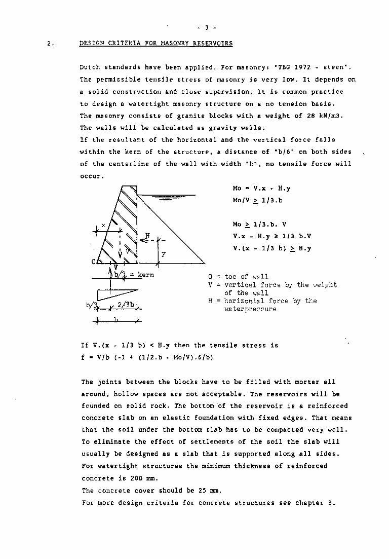
If the resultant of the horizontal and the vertical force falls
within the kern of the structure, a distance of "b/6" on both sides
of the centerline of the wall with width "b", no tensile force will
occur.
Mo - V.x - H.y
Mo/V >. 1/3.b
Mo > 1/3.b. V
V.x - H.y * 1/3 b.V
V.(x - 1/3 b) >. H.y
0 = toe of wallV = vertical force by the weight
of the wallH = horizontal force by the
waterprersure
if.
If V.(x - 1/3 b) < H.y then the tensile stress is
f - V/b (-1 + (1/2.b - Mo/V).6/b)
The joints between the blocks have to be filled with mortar all
around, hollow spaces are not acceptable. The reservoirs will be
founded on solid rock. The bottom of the reservoir is a reinforced
concrete slab on an elastic foundation with fixed edges. That means
that the soil under the bottom slab has to be compacted very well.
To eliminate the effect of settlements of the soil the slab will
usually be designed as a slab that is supported along all sides.
For watertight structures the minimum thickness of reinforced
concrete is 200 mm.
The concrete cover should be 25 mm.
For more design criteria for concrete structures see chapter 3.
- 4 -
3. DESIGN CRITERIA FOR ELEVATED REINFORCED CONCRETE RESERVOIRS
Originally the Dutch concrete specifications of 1961 (GBV) have been
used for the design.
To date more stringent rules for the design of concrete water
retaining structures are applicable; for reinforced concrete:
VB 1974/84.
The water reservoir has to be watertight.
According to the Dutch standards VB 74/84 the minimum thickness of
walls and bottom slab should be 200 mm.
The walls have to have a minimum concrete cover to the outside
reinforcement of 30 mm. The bottom slab has to have a minimum cover
of 25 mm.
In Yemen it is normal to use mild steel while the quality of the
concrete is not high. Therefore concrete structures will be designed
for mild steel FeB 220, tensile strength is 220 N/mm^, and a quality
of concrete B 17.5. For columns, however, high yield steel FeB 400
will be used!
The minimum reinforcement for watertight structures is 0.22 of the
concrete area.
The walls will be considered as slabs with three fixed edges. The
bottom slab will be considered as a slab with four fixed edges.
The design of the water reservoir has to be very simple. Complicated
formwork is unacceptable.
Complicated formwork of reinforced concrete will affect the quality
of the structure negatively, because it becomes difficult to
compact the concrete properly.
The foundation of the elevated r.c. reservoirs consists of
reinforced concrete columns on footings founded on solid rock.
The framework of columns and beams will be calculated taking the
vertical load from the water compartment, horizontal wind forces
and earthquake forces into account.
- 5 -
Technical data:
- concrete quality B 17-5
- allowable ultimate shear stress 0.55 N/mm2
- allowable ultimate punching shear stress 1.10 N/mm2
- the characteristic cube strength is 17.5 N/mm^, which means: the
average cube strength of concrete test cubes made on the site
should reach a value of at least 27.0 N/mm^.
- 6 -
4. COMPARISON OF THE EXISTING STANDARD DESIGN OF MASONRY WATER
RESERVOIRS AND R.C. ELEVATED WATER RESERVOIRS WITH THE DESIGN
CRITERIA NOW APPLICABLE
4.1 Masonry reservoirs
Structural calculations of the existing masonry reservoirs are not
available anymore.
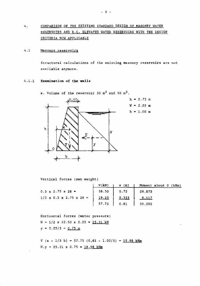
4.1.1 Examination of the walls
a. Volume of the reservoir 30 and 50
h = 2.75 m
W - 2.25 m
b - 1.00 m
Vertical forces (own weight)
0.5 x 2.75 x 28 -
1/2 x 0.5 x 2.75 X 28 =
V(kN)
38.50
19.25
57.75
x (m)
0.75
0.333
0.61
Moment about 0 (kNm)
28.875
6.417
35.292
Horizontal forces (water pressure)
H - 1/2 x 22.50 x 2.25 = 25.31 kN
y = 2.25/3 = 0.75 m
V (x - 1/3 b) = 57.75 (0,61 - 1.00/3) = 15.98 kNm
H.y - 25.31 x 0.75 - 18.98 kNm
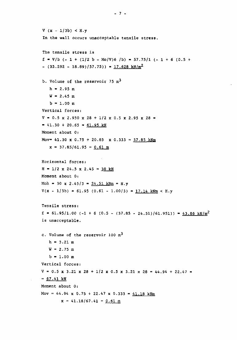
_ 7 -
V (x - l/3b) < H.y
In the wall occurs unacceptable tensile stress.
The tensile stress is
f - V/b (- 1 + (1/2 b - Mo/V)6 /b) - 57.75/1 ( - 1 + 6 (0.5 +
- (35.292 - 18.89)/57.75)) - 17.628 kN/m2
b. Volume of the reservoir 75 m3
h - 2.95 m
W - 2.45 m
b » 1.00 m
Vertical forces:
V - 0.5 x 2.950 x 28 + 1/2 x 0.5 x 2.95 x 28 -
- 41.30 + 20.65 - 61.95 kN
Moment about 0:
Mov- 41.30 x 0.75 + 20.65 x 0.333 =• 37.85 kNm
x - 37.85/61.95 = 0.61 m
Horizontal forces:
H = 1/2 x 24.5 x 2.45 - 30 kN
Moment about 0:
Moh - 30 x 2.45/3 - 24.51 kNm = H.y
V(x - l/3b) - 61.95 (0.61 - 1.00/3) - 17.14 kNm < H.y
Tensile stress:
f - 61.95/1.00 (-1 + 6 (0.5 - (37.85 - 24.51)/61.951)) - 43.86 kN/m2
is unacceptable.
c. Volume of the reservoir 100 m^
h - 3.21 m
W =• 2.75 m
b * 1.00 m
Vertical forces:
V = 0.5 x 3.21 x 28 + 1/2 x 0.5 x 3.21 x 28 = 44.94 + 22.47 -
= 67.41 kN
Moment about 0:
Mov = 44.94 x 0.75 + 22.47 x 0.333 - 41.18 kNm
x = 41.18/67.41 = 0.61 m
- 8 -
Horizontal forces:
H - 1/2 x 27.50 x 2.75 = 37.81 kN
Moment about 0:
Moh - 37.81 x 2.75/3 - 34.66 kNm - H.y
V(x - l/3b) = 67.41 (0.61 - 1.00/3) =• 18.65 kNm < H.y
Tensile stress:
f = 67.41/1.00 ( - 1 + 6 (0.5 - (41.18 - 34.66)/67.41)) = 95.70 kN/m2
d. Volume of the reservoir 250 m^
h = 3.38 m
W - 2.88 m
b - 1.60 m
Vertical forces:
V - 0.5 x 3.38 x 28 + 1/2 x 1.10 X 3.38 x 28 = 47.32 + 52.05 =
= 99-37 kN
Moment about 0:
Mov » 47.32 x 1.35 + 52.05 x 0.733 = 102.05 kNm
x - 102.05/99.37 - 1.03 m
Horizontal forces:
H - 1/2 x 28.8 x 2.88 = 41.47 kN
Moment about 0:
Moh = 41.47 x 2.88/3 - 39.81 kNm » H.y
V(x - 1/3 b) = 99.37(1.03 - 1.6/3) = 49.35 kNm > H.y
In the wall occurs no tensile stress.
4.1.2 Examination of the bottom slab
All reservoirs have a bottom slab of reinforced concrete with a
thickness of 150 mm.
The reinforcement consists of a single cross net at the bottom of
the slab.
- 9 -
For the 250 m 3 reservoir this cross net consists of bars of 4> 16 c/c
150 mm.
For all other reservoirs the cross net consists of bars <{> 12 c/c
150 mm.
There is no reinforcement for negative bending moments along the
edges. The thickness of the slab is less than 200 mm which is a
minimum for watertight structures.
4.1.3 Conclusions
The bottom slab of all reservoirs has a thickness of 150 mm which is
not sufficient to guarantee watertightness and there is no
reinforcement for negative bending moments along the edges.
The masonry walls of the 250 m3 reservoirs have a thickness of 1.6 m
which is sufficient.
The masonry walls of the other reservoirs have a thickness of 1.0 m
which is not sufficient to prevent tensile stress.
Modification of the design is recommended, to fulfill the
requirements of the now applicable standards.
4.2 Elevated reinforced concrete reservoirs
Only preliminary structural calculations are available. Concerning
the foundation and the frames there are no remarks.
4.2.1. Examination of the elevated water reservoir
There are two standard reservoirs, 50 m3 and 15 m3. Both reservoirs
have walls and a bottom slab with a thickness of 150 mm.
The bottom slab is supported by concrete beams in both directions.
Those beams together with the bottom slab, the walls and the columns
of the frames form one complete structure without joints.
- 10 -
The walls and bottom slab of the 15 m reservoir have a
reinforcement consisting of a double cross net <|> 12 c/c 125 nun. For
the 50 m^ reservoir it is (j) 8 c/c 120 mm. For watertight reinforced
concrete structures a thickness of 150 mm for walls and bottom slab
is not sufficient according to the new applicable standards.
According to the Dutch standards now in force this has to be 200 mm.
The form work of the bottom slab with beams is rather complicated.
This means that also the reinforcement is complicated and that it
is difficult to pour and compact the concrete properly.
4.2.2 Conclusion
For a contractor it is very difficult to construct a watertight
water reservoir without cracks if he has to execute it according to
the existing standard designs.
Modification of the design is recommended.
- 11 -
5. REVIEW OF THE DESIGN AND STRUCTURAL CALCULATIONS FOR MASONRY
RESERVOIRS
5.1 General cross section
See figure 2, chapter 10
Main demensions:
See figure 4-1 to 4-3, chapter 10
Reservoir
(m3)
30
50
75
100
250*
Lx
(m)
3.50
4.50
4.50
5.00
8.70
Ly
(m)
4.20
5.20
6.70
7.20
10.50
W
(m)
2.10
2.20
2.55
2.85
3.00
h
(m)
2.35
2.45
2.80
3.10
3.25
* The 250 m3 reservoirs have a load bearing wall with a width of
1.00 m in the middle of the span.
5.2 Top slabs
See figure 4-4 and 4-5, chapter 10
Concrete: B 17.5
Reinforcement: mild steel
Concrete cover to the reinforcement: 20 mm
Thickness = tl > 1/35 lx + 20 mm (lx in millimeters)
Dead load - 24 tl kN/m2 (tl in meters)
Live load - 0.5 kN/m2
q - dead load + live load
The possitive moment per unit length in middle section parallel to
the long edge (ly) is Mvx.
The possitive moment per unit length in middle section parallel to
the short edge (lx) is Mvy.
See table E8 of chapter 8
lv/lx
Mvx =
Mvy •
0.
0.
001
001
qlx2
qlx2
X
X
1.
50
36
14
.1
.8
1.
52
35
18
.7
.6
1.
59
33
28
.2
.4
1.
67
31
40
.0
.0
2.
110
23
53
.4
.9
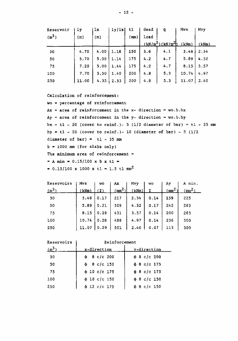
- 12 -
Reservoir
(m3)
30
50
75
100
250
ly
(m)
4.70
5.70
7.20
7.70
11.00
lx
(m)
4.00
5.00
5.00
5.50
4.35
ly/lx
1.18
1.14
1.44
1.40
2.53
tl
(mm)
150
175
175
200
200
dead
load
q
(kN/m2HkN/m2
3.6
4.2
4.2
4.8
4.8
4.1
4.7
4.7
5.3
5.3
Mvx
) (kNm)
3.46
5.89
8.15
10.74
11.07
Mvy
(kNm)
2.34
4.32
3.57
4.97
2.40
Calculation of reinforcement:
wo = percentage of reinforcement
Ax = area of reinforcement in the x- direction •= wo.b.hx
Ay = area of reinforcement in the y- direction = wo.b.hy
hx = tl - 20 (cover to reinf.)- 5 (1/2 diameter of bar) = tl - 25 mm
hy = tl - 20 (cover to reinf.)- 10 (diameter of bar) - 5 (1/2
diameter of bar) - tl - 35 mm
b « 1000 mm (for slabs only)
The minimum area of reinforcement =
- A min = 0.15/100 x b x tl =
- 0.15/100 x 1000 x tl » 1.5 tl mm2
Reservoirs
(m3)
30
50
75
100
250
Mvx
(kNm)
3.46
5.89
8.15
10.74
11.07
wo
(X)
0.17
0.21
0.29
0.28
0.29
Ax
(mm2)
217
309
431
486
501
Mvy(kNm)
2.34
4.32
3.57
4.97
2.40
wo
%
0.14
0.17
0.14
0.14
0.07
Ay
(mm2)
159
242
200
236
113
A min.
(mm2)
225
263
263
300
300
Reservoirs
(m3)
30
50
75
100
250
Reinforcement
x-direction
4> 8 c/c 200
<)> 8 c/c 150
<|> 10 c/c 175
<|> 10 c/c 150
* 12 c/c 175
V
-e--e-
*
-direction
8 c/c 200
8 c/c 175
8 c/c 175
8 c/c 150
8 c/c 150
- 13 -
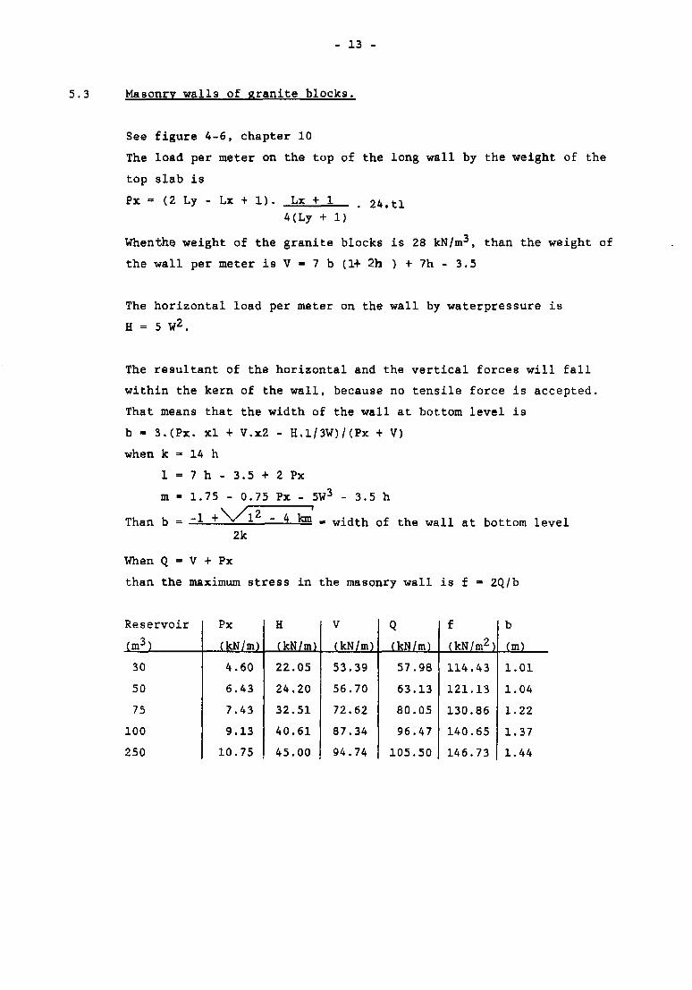
5.3 Masonry walls of granite blocks.
See figure 4-6, chapter 10
The load per meter on the top of the long wall by the weight of the
top slab is
Px - (2 Ly - Lx + 1). Lx + 1 # 24.tl
4(Ly + 1)
Whenthe weight of the granite blocks is 28 kN/m3, than the weight of
the wall per meter is V - 7 b (1+ 2h ) + 7h - 3.5
The horizontal load per meter on the wall by waterpressure is
H = 5 W2.
The resultant of the horizontal and the vertical forces will fall
within the kern of the wall, because no tensile force is accepted.
That means that the width of the wall at bottom level is
b - 3.(Px. xl + V.x2 - H.l/3W)/(Px + V)
when k =• 14 h
l = 7 h - 3 . 5 + 2 P x
m - 1.75 - 0.75 Px - 5W3 - 3.5 h
= - 1 + \ / l 2 - 4 km „ Width of the wall at bottom levelThan b =2k
When Q = V + Px
than the maximum stress in the masonry wall is f - 2Q/b
Reservoir
(m3)
30
50
75
100
250
Px
(kN/m)
4.60
6.43
7.43
9.13
10.75
H
(kN/m)
22.05
24.20
32.51
40.61
45.00
V
(kN/m)
53.39
56.70
72.62
87.34
94.74
Q
(kN/m)
57.98
63.13
80.05
96.47
105.50
f
(kN/m2)
114.43
121.13
130.86
140.65
146.73
b
(m)
1.01
1.04
1.22
1.37
1.44
- 14 -
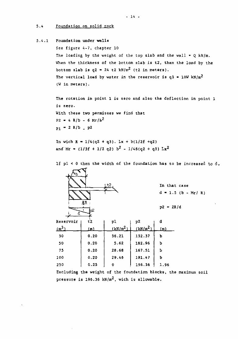
5.4 Foundation on solid rock
5.4.1 Foundation under walls
See figure 4-7, chapter 10
The loading by the weight of the top slab and the wall * Q kN/m.
When the thickness of the bottom slab is t2, than the load by the
bottom slab is q2 - 24 t2 kN/m2 (t2 in meterB).
The vertical load by water in the reservoir is q3 - 10W kN/m2
(W in meters).
The rotation in point 1 is zero and also the deflection in point 1
is zero.
With these two permisses we find that
P2 - 4 R/b - 6 Mr/b2
P 1 - 2 R/b . p2
In wicn R - l/4(q2 + q3). Lx + b(l/2f +q2)
and Mr - (l/3f + 1/2 q2) b 2 - l/48(q2 + q3) Lx 2
If pi < 0 then the width of the foundation has to be increased to cl.
In that case
d - 1.5 (b - Mr/ R)
p2 - 2R/d
Reservoir
(m3)
30
50
75
100
250
t2
(m)
0.20
0.20
0.20
0.20
0.25
Pi
(kN/m2)
36.21
5.62
28.68
29.46
0
p2
(kN/m2)
132.37
182.96
167.51
181.47
196.36
d(m)
b
b
b
b
1.96
Excluding the weight of the foundation blocks, the maximum soil
pressure is 196.36 kN/m2, wich is allowable.
- 15 -
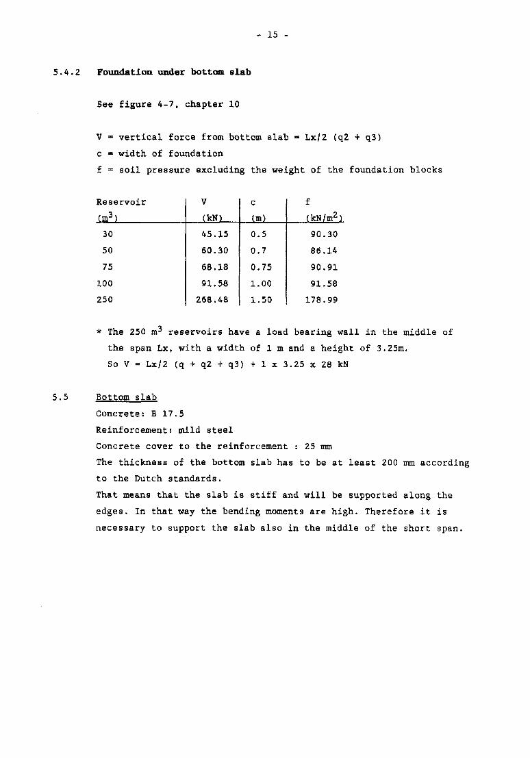
5.4.2 Foundation under bottom slab
See figure 4-7, chapter 10
V - vertical force from bottom slab - Lx/2 (q2 + q3)
c « width of foundation
f = soil pressure excluding the weight of the foundation blocks
Reservoir
tm3)
30
50
75
100
250
VfkN)
45.15
60.30
68.18
91.58
268.48
c(m)
0.5
0.7
0.75
1.00
1.50
f(kN/m2)
90.30
86.14
90.91
91.58
178.99
* The 250 m3 reservoirs have a load bearing wall in the middle of
the span Lx, with a width of 1 m and a height of 3.25m.
So V = Lx/2 (q + q2 + q3) + 1 x 3.25 x 28 kN
5.5 Bottom slab
Concrete: B 17.5
Reinforcement: mild steel
Concrete cover to the reinforcement : 25 mm
The thickness of the bottom slab has to be at least 200 mm according
to the Dutch standards.
That means that the slab is stiff and will be supported along the
edges. In that way the bending moments are high. Therefore it is
necessary to support the slab also in the middle of the short span.
- 16 -
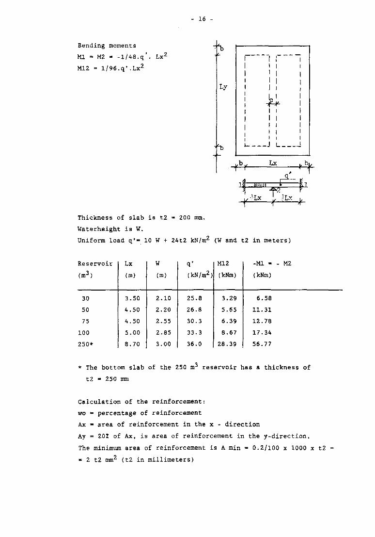
Bending moments
Ml = M2 - -1/48.q'. Lx 2
M12 = l/96.q'.Lx2
—
1
1111
i
i1iii
i
Iiii
L__
11
11I
11111111
Lx
Thickness of slab is t2 » 200 mm.
Waterheight is W.
Uniform load qf= 10 W + 24t2 kN/m2 (W and t2 in meters)
Reservoir
(m3)
30
50
75
100
250*
Lx
(m)
3.50
4.50
4.50
5.00
8.70
W(m)
2.10
2.20
2.55
2.85
3.00
q'
(kN/m2)
25.8
26.8
30.3
33.3
36.0
Ml 2
(kNm)
3.29
5.65
6.39
8.67
28.39
-Ml - - M2
(kNm)
6.58
11.31
12.78
17.34
56.77
* The bottom slab of the 250 m3 reservoir has a thickness of
t2 =• 250 mm
Calculation of the reinforcement:
wo - percentage of reinforcement
Ax - area of reinforcement in the x - direction
Ay = 20Z of Ax, is area of reinforcement in the y-direction.
The minimum area of reinforcement is A min - 0.2/100 x 1000 x t2
« 2 t2 mm2 (t2 in millimeters)
- 17 -
Reservoir
(m3)
30
50
75
100
250
-Ml -
- M2
(kNm)
6.58
11.31
12.78
17.34
56.77
wo
(X)
0.18
0.31
0.35
0.48
1.02
Ax
(mm2)
304
528
599
823
2218
Ay
(mm2)
61
106
120
165
444
+M12
(kNm)
3.29
5.65
6.39
8.67
28.39
Ax
(mm2)
151
260
295
402
1055
Ay
(mm2)
31
52
59
81
211
Amin
(mm2,)
400
400
400
400
500
- 18 -
6. REVIEW OF THE DESIGN AND STRUCTURAL CALCULATIONS FOR ELEVATED
REINFORCED CONCRETE RESERVOIRS
Concrete: B 17.5
Reinforcement:
- columns high yield steel FeB 400
- walls, slabs, beams and footings mild steel FeB 220
Concrete cover:
- walls and bottom slab of the water compartment 25 mm
- columns, beams and footings 30 mm
- platform slab and top slab 15 mm
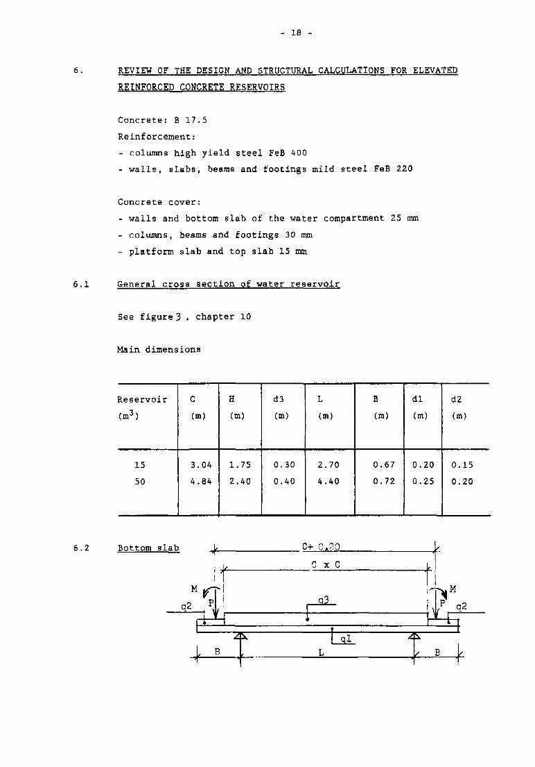
6.1 General cross section of water reservoir
See figure 3 . chapter 10
Main dimensions
Reservoir
(m3)
15
50
C
Cm)
3.04
4.84
H
(m)
1.75
2.40
d3
Cm)
0.30
0.40
L
(m)
2.70
4.40
B
(m)
0.67
0.72
d l
(m)
0.20
0.25
d2
(m)
0.15
0.20
6.2 Bottom slab C+ 0.20
G x C
- 19 -
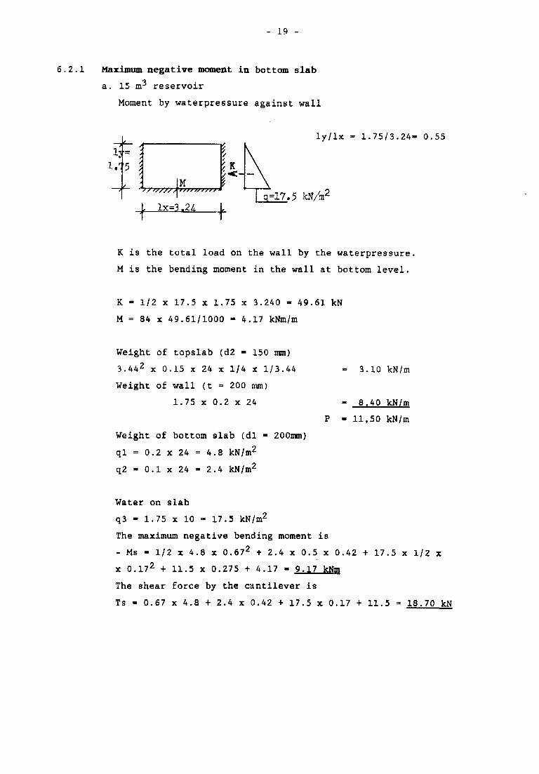
6.2.1 Maximum negative moment in bottom slab
a. 15 m^ reservoir
Moment by waterpressure against wall
ly/lx - 1.75/3.24- 0.55
q=17.5
K is the total load on the wall by the waterpressure,
M is the bending moment in the wall at bottom level.
K - 1/2 x 17.5 x 1.75 x 3.240 - 49.61 kN
M = 84 x 49.61/1000 - 4.17 kNm/m
Weight of topslab (d2 = 150 mm)
3.442 x 0.15 x 24 x 1/4 x 1/3.44
Weight of wall (t - 200 mm)
1.75 x 0.2 x 24
Weight of bottom slab (dl - 200mm)
ql = 0.2 x 24 = 4.8 kN/m2
q2 - 0.1 x 24 - 2.4 kN/m2
** 3.10 kN/m
- 8.40 kN/m
- 11,50 kN/m
Water on slab
q3 - 1.75 x 10 - 17.5 kN/m2
The maximum negative bending moment is
- Ms = 1/2 x 4.8 x 0.672 + 2.4 x 0.5 x 0.42 + 17.5 x 1/2 x
x 0.172 + 11.5 x 0.275 + 4.17 - 9.17 kNm
The shear force by the cantilever is
Ts - 0.67 x 4.8 + 2.4 x 0.42 + 17.5 x 0.17 + 11.5 = 18.70 kN
- 20 -
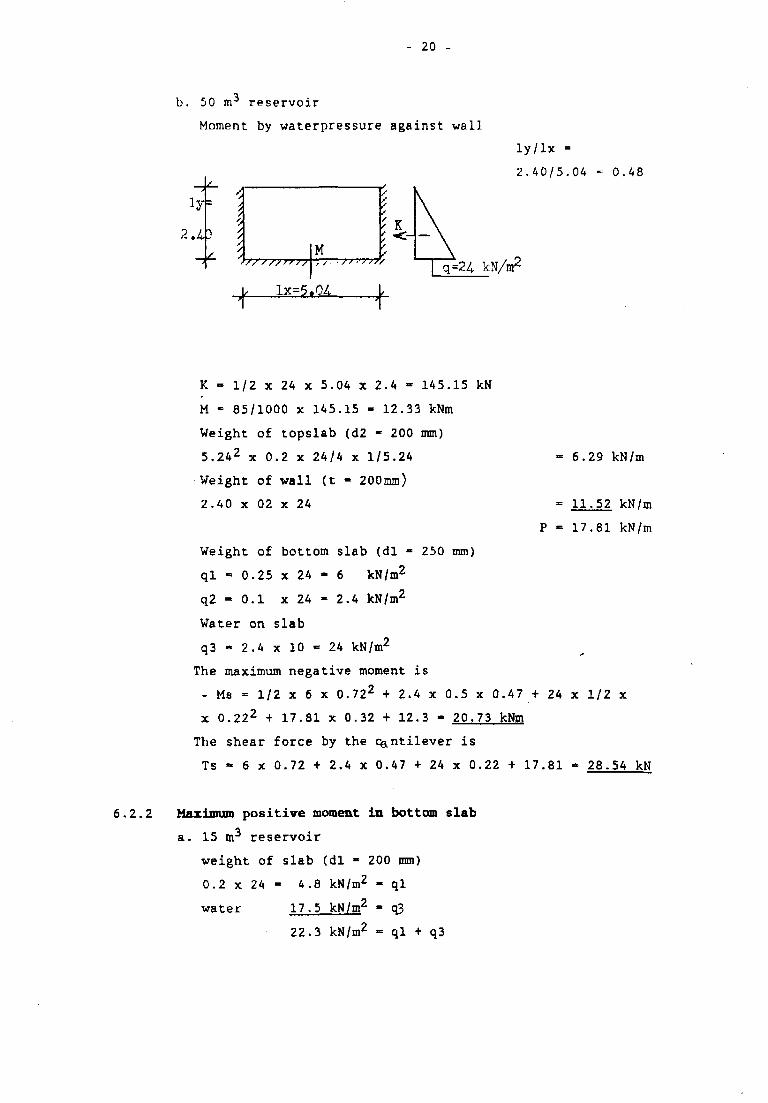
b. 50 m3 reservoir
Moment by waterpressure against wall
ly/lx =
2.40/5.04 - 0.48
kN/m2
- 6.29 kN/m
= 11.52 kN/m
P - 17.81 kN/m
K - 1/2 x 24 x 5.04 x 2.4 - 145.15 kN
M - 85/1000 x 145.15 - 12.33 kNm
Weight of topslab (d2 - 200 mm)
5.242 x 0.2 x 24/4 x 1/5.24
Weight of wall (t - 200mm)
2.40 x 02 x 24
Weight of bottom slab (dl - 250 mm)
ql - 0.25 x 24 - 6 kN/m2
q2 = 0.1 x 24 - 2.4 kN/m2
Water on slab
q3 • 2.4 x 10 •= 24 kN/m2
The maximum negative moment is
- Ms - 1/2 x 6 x 0.722 + 2.4 x 0.5 x 0.47 + 24 x 1/2 x
x 0.222 + 17.81 x 0.32 + 12.3 - 20.73 kNm
The shear force by the Cantilever is
Ts - 6 x 0.72 + 2.4 x 0.47 + 24 x 0.22 + 17.81 - 28.54 kN
6.2.2 Mwriimm positive moment in bottom slab
a. 15 m3 reservoir
weight of slab (dl - 200 mm)
0.2 x 24 - 4.8 kN/m2 - ql
water 17.5 kN/m2 - q3
22.3 kN/m2 = ql + q3
- 21 -
Bending moments in x and y direction:
Mx - 41/1000 x 22.3 x 2.72 - 9.17 = - 2.5 kNm
My - Mx
no positive moment I
Shear force:
Ts - 2.7/2 x 22.3 - 30.11 kN/m
b. 50 m^ reservoir
weight of slab (dl - 250 mm)
0.25 x 24 - 6 kN/m2 - ql
water 24 kN/m2 - q3
30 kN/m2 - ql + q3
Bending moments in x and y directions:
My - Mx - 41/1000 x 30 x 4.42 - 20.73 - 3.08 kNm
Shear force:
Ts - 4.4/2 x 30 - 66 kN/m
6.2.3 Check on shear force
a. 15 m^ reservoir
Max. shear force is T max. - 30.11 kN/m
200 mm bottom slab
h - 200 - 25 - 10 - 5 - 160 mm
Max. shear stress is ft = 1.7 x 30.11 /160 - 0.32 N/mm2 is
acceptable.
b. 50 m^ reservoir
Max. shear force is T max = 66 kN/m
250 mm bottom slab
h - 250 - 25 - 10 - 5 - 210 mm
Max. shear stress is ft - 1.7 x 66/210 = 0.54 N/mm2 is acceptable
- 22 -
6.2.4 Reinforcement
a. 15 m 3 reservoir,
dl = 200 mm.
Minimum area of reinforcement is A min = 400 innr-
wo is percentage of reinforcement
- Mx = - My - 9.17 kNm.
wo = 0.28 Aa = 454 mm2
- M x = - M y = 2 . 5 kNm
wo = 0.08 Aa = 400 mm2 (minimum reinforcement A min)
b. 50 m^ reservoir,
dl = 250 mm
Minimum area of reinforcement is A min - 500 mm
- Mx = - My - 20.73 kNm
wo = 0.38 Aa = 788 mm2
+ Mx = + My - 3.08 kNm
wo = 0.05 Aa = 500 mm2 (minimum reinforcement Amin)
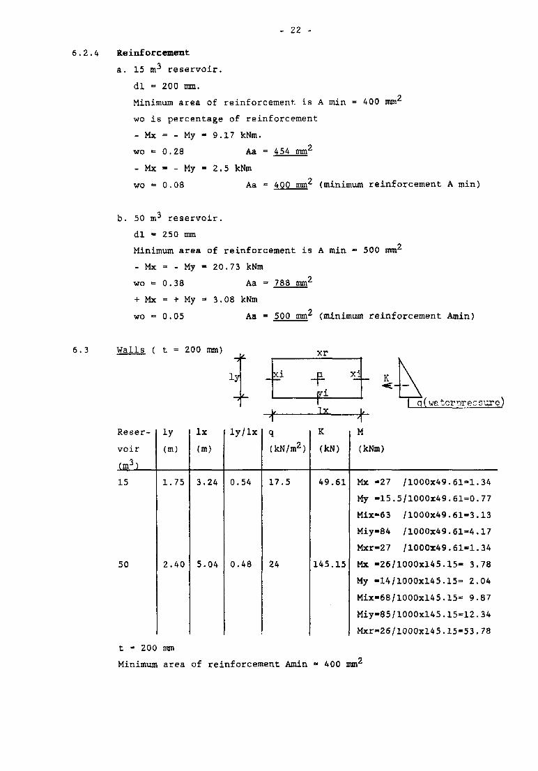
6.3 Walls ( t = 200 mm)-if- xr
\
| q(waterpre.TSure)
Reser-
voir
(m3)
15
50
iy
(m)
1.75
2.40
lx
(m)
3.24
5.04
ly/lx
0.54
0.48
q
(kN/m2)
17.5
24
IX
K
(kN)
49.61
145.15
M
(kNm)
Mx -27 /1000X49.61-1.34
My -15.5/1000x49.61-0.77
Mix-63 /1000x49.61-3.13
Miy-84 /1000x49.61-4.17
Mxr-27 /1000x49.61-1.34
Mx -26/1000x145.15- 3.78
My -14/1000x145.15= 2.04
Mix-68/1000xl45.15- 9.87
Miy=85/1000x145.15=12.34
Mxr-26/1000x145.15-53.78
t - 200 mm
Minimum area of reinforcement Amin - 400 mm2
- 23 -
6.4
a. Reservoir 15 m3.
The maximum moment is Mmax. =4.17 kNm - Miy
wo = 0.11 Aa - 400 mm2 •=• Amin
Shear: Tmax - 1/2 x 17.5 x 1.75 - 15.31 kN/m'
Shear stress: ft - (1.7 x 15.3D/160 - 0.16 N/mm2
b. Reservoir 50 m3.
Shear: Tmax - 1/2 x 24 x 2.4 - 28.8 kN/m
Shear stress: ft = 1.7 x 28.8/160 - 0.31 N/mm2
Mx -
My -
Mix -
Miy -
Mxr -
Too slab
3.78
2.04
9.87
12.34
3.78
kNm,
kNm,
kNm,
kNm,
kNm,
h -
h -
h -
h -
h -
160
170
160
170
160
mm,
nun,
mm,
mm,
mm,
wo •
WO ™
wo =
wo =
wo •
0.12,
0.05,
0.31,
0.34,
0.12,
A -
A =
A -
A =
A -
400
400
490
578
400
mm2
mm2
mm2
mm2
mm2
= Amin
= Amin
= Amin
lx = ly - C + t (see fig. 3, chapter 10)
Reservoir
(m3)
15
50
lx -
- iy
(m)
3.24
5.04
d2
Cm)
0.15
0.20
live
load
(kN/m2
0.5
0.5
dead
load
(kN/m2)
3.60
4.80
q -
total
load
(kN/m2)
4.10
5.30
a. 15 m3 reservoir
d2 = 150 mm
Minimum area of reinforcement is Amin • 300 mm2
Maximum bending moments in x and y direction:
Mx - My = 41/1000 x 4.1 x 3.242 - 1.76 kNm
Percentage of reinforcement wo » 0.10
Aa » 300 mm2 » Amin
6.5
b. 50 m^ reservoir
d2 - 200 mm
Minimum area of reinforcement is Amin •= 400 mm4
Maximum bending moments in x and y direction:
Mx - My - 41/1000 x 5.3 x 5.042 - 5.52 kNm
Percentage of reinforcement wo - 0.15
Aa •» 400 moi Amin
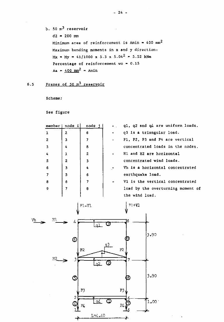
Frames of 50 m reservoir
Scheme;
See figure
member
1
2
3
4
5
6
7
8
9
node i
2
3
4
1
2
3
5
6
7
node j
6
7
8
2
3
4
6
7
8
PI-VI
al T3T
P3
ql, q2 and q4- are uniform loads.
q3 is a triangular load.
PI, P2, P3 and P4 are vertical
concentrated loads in the nodes.
HI and H2 are horizontal
concentrated wind loads.
Vh is a horizontal concentrated
earthquake load.
VI is the vertical concentrated
load by the overturning moment of
the wind load.
\
Pl+Vl
P3,
3.90
3.90
l.oo
-k-
- 25 -
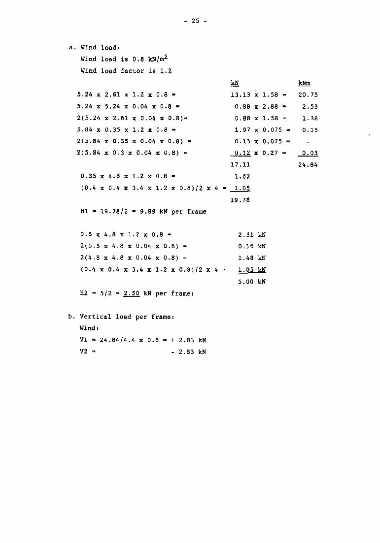
a. Wind load:
Wind load is 0.8 kN/m2
Wind load factor is 1.2
5.24 x 2.61 x 1.2 x 0.8 -
5.24 x 5.24 x 0.04 x 0.8 -
2(5.24 x 2.61 x 0.04 x 0.8)-
5.84 x 0.35 x 1.2 x 0.8 -
2(5.84 x 0.35 x 0.04 x 0.8) =
2(5.84 x 0.3 x 0.04 X 0.8) •=
0.35 x 4.8 x 1.2 x 0.8 =
(0.4 x 0.4 x 3.4 x 1.2 x 0.8)/2 x 4
HI - 19.78/2 - 9.89 kN per frame
0 . 5 x 4 . 8 x 1 . 2 x 0 . 8 - 2.31 kN
2(0.5x4.8x0.04 X 0 . 8 ) = 0.16 kN
2(4.8 x 4.8 x 0.04 x 0.8) = 1.48 kN
(0.4 x 0.4 x 3.4 x 1.2 x 0.8)/2 x 4 = 1.05 kN
5.00 kN
H2 - 5/2 - 2.50 kN per frame:
b. Vertical load per frame:
Wind:
VI = 24.84/4.4 x 0.5 = + 2.83 kN
V2 - - 2.83 kN
kN
13.13
0.88
0.88
1.97
0.13
0.12
17.11
1.62
1.05
19.78
X
X
X
X
X
X
1.58 -
2.88 -
1.58 =
0.075 -
0.075 -
0.27 =
kNm
20.75
2.53
1.38
0.15
0.03
24.84
- 26 -
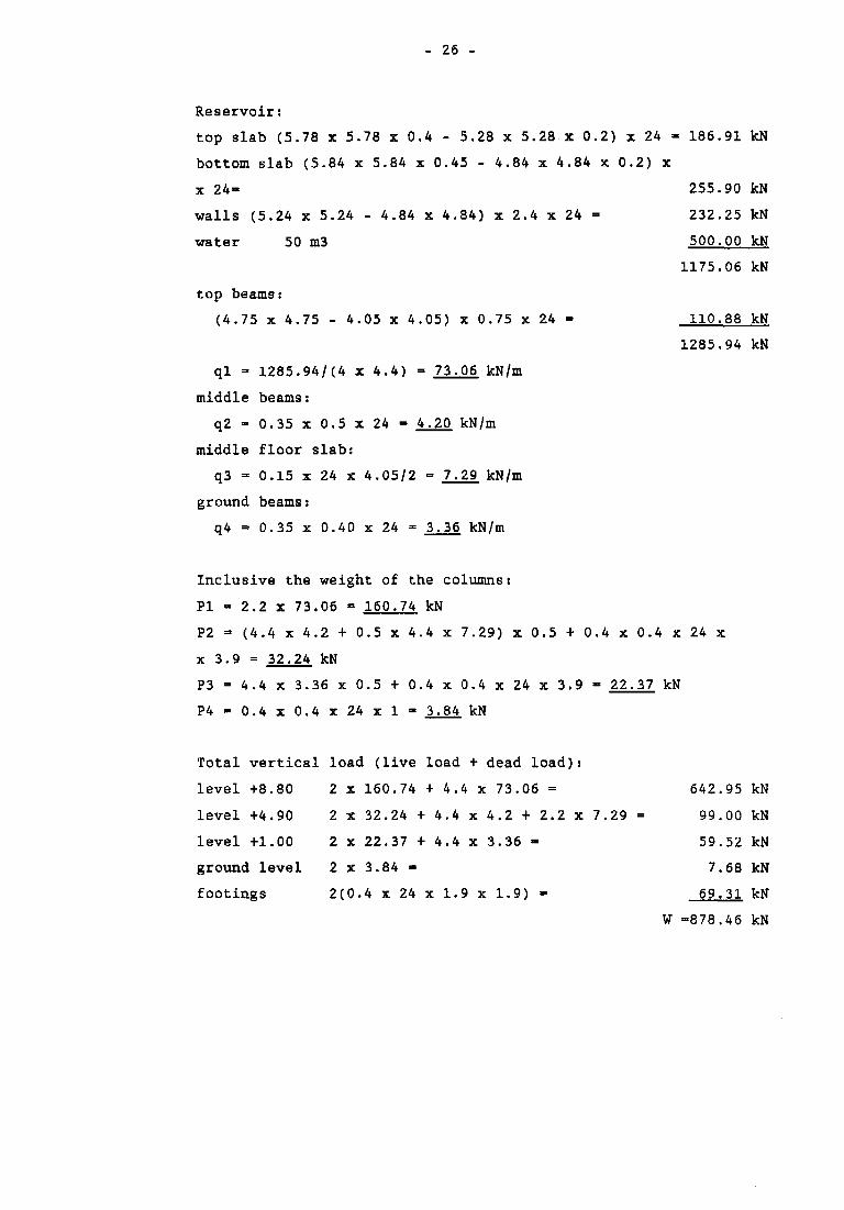
Reservoir:
top slab (5.78 x 5.78 x 0.4 - 5.28 x 5.28 x 0.2) x 24 - 186.91 kN
bottom slab (5.84 x 5.84 x 0.45 - 4.84 x 4.84 x 0.2) x
x 24- 255.90 kN
walls (5.24 x 5.24 - 4.84 x 4.84) x 2.4 x 24 = 232.25 kN
water 50 m3 500.00 kN
1175.06 kN
top beams:
(4.75 x 4,75 - 4.05 x 4.05) x 0.75 X 24 - 110.88 kN
1285.94 kN
ql = 1285.94/(4 x 4.4) = 73.06 kN/m
middle beams:
q2 - 0.35 x 0.5 x 24 - 4.20 kN/m
middle floor slab:
q3 => 0.15 x 24 x 4.05/2 = 7.29 kN/m
ground beams:
q4 = 0.35 x 0.40 x 24 = 3.36 kN/m
Inclusive the weight of the columns:
PI - 2.2 x 73.06 - 160.74 kN
P2 =• (4.4 x 4.2 + 0.5 x 4.4 x 7.29) x 0.5 + 0.4 x 0.4 x 24 x
x 3.9 = 32.24 kN
P3 - 4.4 x 3.36 x 0.5 + 0.4 x 0.4 x 24 x 3.9 - 22.37 kN
P 4 - 0 . 4 x 0 . 4 x 2 4 x l « 3.84 kN
Total vertical load (live load + dead load):
level +8.80 2 x 160.74 + 4.4 x 73.06 = 642.95 kN
level +4.90 2 x 32.24 + 4.4 x 4.2 + 2.2 x 7.29 = 99.00 kN
level +1.00 2 X 22.37 + 4.4 x 3.36 - 59.52 kN
ground level 2 x 3.84 - 7.68 kN
footings 2(0.4 x 24 x 1.9 x 1.9) - 69.31 kN
W -878.46 kN
- 27 -
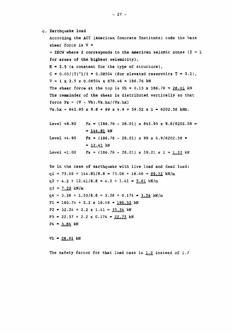
c. Earthquake load
According the ACI (American Concrete Institute) code the base
shear force is V -
• ZKCW where Z corresponds to the American seismic zones (Z = 1
for areas of the highest seismicity),
K - 2.5 (a constant for the type of structure),
C - 0.05/(T)"l/3 - 0.08504 (for elevated reservoirs T = 0.2),
V * 1 x 2.5 x 0.08504 X 878.46 - 186.76 kN
The shear force at the top is Vh - 0.15 x 186.76 •= 28.01 kN
The remainder of the shear is distributed vertically so that
force Fx = (V - Vh).Vx.hx/(Vx.hx)
Vx.hx - 642.95 x 8.8 + 99 x 4.9 + 59.52 x 1 = 6202.58 kNm.
Level +8.80 Fx - (186.76 - 28.01) x 642.95 x 8.8/6202.58 =
- 144.81 kN
Level +4.90 Fx - (186.76 - 28.01) x 99 x 4.9/6202.58 -
» 12.41 kN
Level +1.00 Fx - (186.76 - 28.01) x 59.21 x 1 = 1.53 kN
So in the case of earthquake with live load and dead load:
ql - 73.06 + 144.81/8.8 - 73.06 + 16.46 = 89.52 kN/m
q2 - 4.2 + 12.41/8.8 - 4.2 + 1.41 - 5.61 kN/m
q3 = 7.29 kN/m
q4 = 3.36 + 1.53/8.8 =• 3.36 + 0.174 - 3.54 kN/m
PI - 160.74 + 2.2 x 16.46 - 196.52 kN
P2 - 32.24 + 2.2 x 1.41 - 35.34 kN
P3 - 22.37 + 2.2 x 0.174 - 22.75 kN
P4 - 3.84 kN
Vh - 28.01 kN
The safety factor for that load case is 1.2 instead of 1.7
- 28 -
d. Modulus of elasticity
E is the modulus of elasticity
I is the moment of inertia
Columns:
dimension 0.40 x 0.40 m
assume that the percentage of reinforcement wo - 0.75
E - 1/3 x (8wo + 10) x 106 = 5.33 x 10⁶ kN/m2
El - 5.33 x 106 x 1/12 x 0.40 x 403 - 11370 kNm2
Top beams:
dimension 0.35 x 0.75 m
assume wo =• 0.5
E - (7.5wo + 2.5) x 106 - 6.25 x 10⁶ kN/m2
El - 6.25 x 106 x 1/12 x 0.35 x 0.753 - 76904 kNm2
Middle beams:
dimension 0.35 x 0.5 m
assume wo - 0.68
E = (7.5wo + 2.5) x 106 = 7.60 x 10⁶ kN/m2
El = 7.60 x 106 x 1/12 x 0.35 x 0.53 - 27708 kNm2
Ground beams:
dimension 0.35 x 0.40 m
assume wo • 1.00
E - (7.5wo + 2.5) x 106 = 10 x 106 kN/m2
El = 10.00 x 106 x 1/12 x 0.35 x 0.43 = 18666 kNm2
e. Load case
1. dead load + live load + wind
2. dead load + live load + earthquake
f. Calculation of the member forces
See computer output at page 7 to 14, chapter 9.
g. Calculation of the second moment factor n/(n - 1)
The second moment factor n/(n-l) depends on the critical
compression loads of the members.
- 29 -
The critical compression load according the theory of Euler is
Nk' m 3.142 EI/Lk2 in wich formula
E » modulus of elasticity
I - moment of inertia
Lk = buckling length
In paragraph 6.5 d the value of El has been calculated for the
several members.
The buckling length of the columns depends on the El value and
the end conditions of the columns and of the properties of the
connected members to the columns.
For the members no. 4, 5 and 6 the buckling length has been
calculated with a computer program.
The result is:
for member no. 4 Lk - 2.51 m
for member no. 5 Lk - 4.31 m
for member no. 6 Lk = 4.23 m
n = Nk /Nd' in wich
Nk • critical compression load
Nd' • design value of the compression load N'
The design value Nd' - 1.7 N'
Nk' = 3.142 x (EI)/Lk2
columns 4 and 7: Nk'
columns 5 and 8: Nk'
columns 6 and 9: Nk*
3.142 x 11370/(2.512) - 17812 kN
3.142 x 11370/(4.312) = 6040 kN
3.142 x 11370/(4.232) - 6271 kN
Load case 1:
column
4
5
6
7
8
9
N*
kN
389
364
319
412
379
324
Nd'
kN
662
619
543
701
643
551
Nk'
kN
17812
6040
6271
17812
6040
6271
n
26.91
9.76
11.45
25.40
9.40
11.38
n/(n - 1)
1.12
All member forces and displacements by the horizontal loads to
be multiplied with 1.12
- 30 -
Load case 2:
Column
4
5
6
7
8
9
N'
kN
424
412
380
536
487
408
Nd'
kN
509
495
456
643
585
598
Nk*
kN
17812
6040
6271
17812
6040
6271
n
35.00
12.20
13.75
27.70
10.33
10.49
n/(n - 1)
1.11
All member forces and displacements by the horizontal loads to
be multiplied with 1.11.
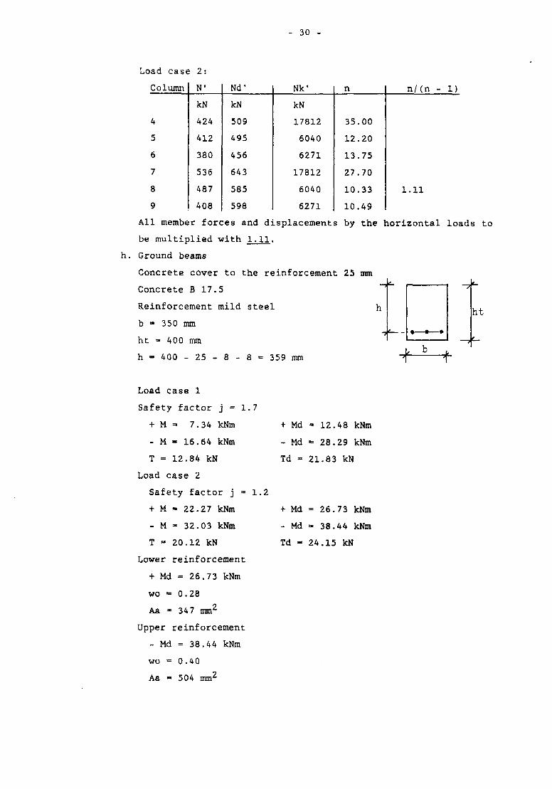
h. Ground beams
Concrete cover to the reinforcement 25 mm
Concrete B 17.5
Reinforcement mild steel h
b » 350 mm
ht = 400 mm
h = 400 - 25 - 8 - 8 = 359 nun
ht
Load case 1
Safety factor j = 1.7
+ M = 7.34 kNm
- M « 16.64 kNm
T = 12.84 kN
Load case 2
Safety factor j = 1.2
+ M » 22.27 kNm
- M - 32.03 kNm
T - 20.12 kN
Lower reinforcement
+ Md = 26.73 kNm
wo = 0.28
Aa * 347 mm^
Upper reinforcement
- Md = 38.44 kNm
wo = 0.40
Aa • 504 mm^
+ Md - 12.48 kNm
- Md = 28.29 kNm
Td - 21.83 kN
+ Md = 26.73 kNm
- Md - 38.44 kNm
Td - 24.15 kN
- 31 -
Because of the beam stiffness (- El) we take for lower as well as
for upper reinforcement:
wo » 0.5
Aa = 130, mm2, or 2 4> 12 + 2 $ 16
Shear force:
Td - 24.15 kN
ft = 24150/350 x 359 = 0.19 N/mm2
gives practical ties of 4> 8 c/c 250 mm
Middle beams
b =•= 350 mm
ht - 500 mm
h - 500 - 25 - 8 - 8 - 459 mm.
Load case 1
safety factor j • 1.7
+ M - 8.15 kNm + Md = 13.86 kNm
- M - 36.88 kNm - Md = 62.69 kNm
T - 27.50 kN Td - 46.75 kN
Load case 2
safety factor j • 1.2
+ M - 38.74 kNm + Md = 65.86 kNm
- M - 73.06 kNm - Md - 87.67 kNm
T - 45.77 kN Td = 54.92 kN
Lower reinforcement:
+ Md = 65.86 kNm
wo = 0.42
Aa - 67J_ mm2, or 2 $ 16 + 2 <}> 12
Upper reinforcement:
- Md - 87.67 kNm
wo =• 0.57
Aa = 913 m2, or 5 * 16
Shear force:
Td - 54.92 kN
ft - 54920/350 x 459 - 0.34 N/mm2,
gives practical ties of <t> 8 c/c 250 mm
- 32 -
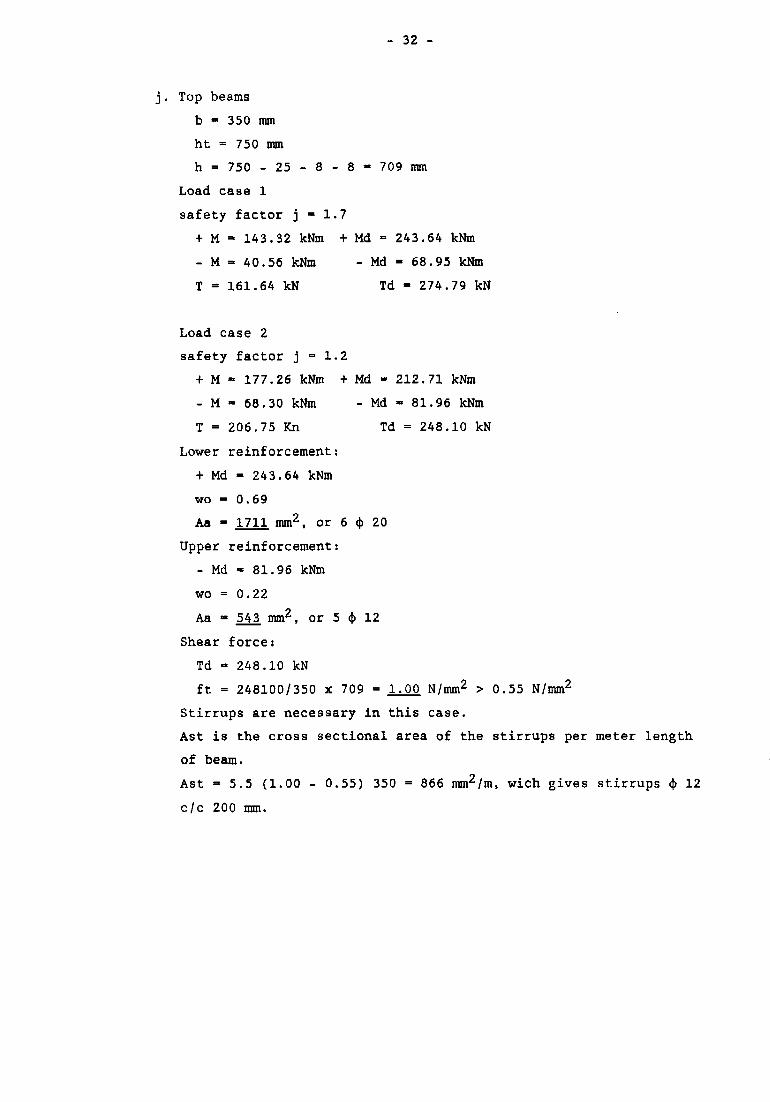
j. Top beams
b - 350 mm
ht = 750 mm
h = 750 - 25 - 8 - 8 - 709 mm
Load case 1
safety factor j • 1.7
+ M - 143.32 kNm + Md = 243.64 kNm
- M = 40.56 kNm - Md - 68.95 kNm
T = 161.64 kN Td - 274.79 kN
Load case 2
safety factor j = 1.2
+ M - 177.26 kNm + Md - 212.71 kNm
- M - 68.30 kNm - Md - 81.96 kNm
T = 206.75 Kn Td = 248.10 kN
Lower reinforcement:
+ Md - 243.64 kNm
wo - 0.69
Aa » 1711 mm2, or 6 <|> 20
Upper reinforcement:
- Md - 81.96 kNm
wo = 0.22
Aa - 543, mm2, or 5 4> 12
Shear force:
Td - 248.10 kN
ft = 248100/350 x 709 = 1.00 N/mm2 > 0.55 N/mm2
Stirrups are necessary in this case.
Ast is the cross sectional area of the stirrups per meter length
of beam.
Ast - 5.5 (1.00 - 0.55) 350 = 866 mm2/m, wich gives stirrups c|) 12
c/c 200 mm.
- 33 -
Platform
Thickness ht » 150 mm
Concrete cover 20 mm
hx = 150 - 20 - 5 - 125 mm
hy - 150 - 20 - 10 - 5 - 115 mm
Concrete B 17.5
Reinforcement: mild steel
ly =• lx » 4.40 m
ly/lx - 1
Dead load 0.15 x 24 - 3.60 kN/m2
Live load 0.50 kN/m2
q - 4.10 kN/m2
Mx - My = 41/100 x 4.10 x 4.42 - 3.25 kNm
Md - 5.53 kNm
h » 115 mm
wo - 0.19
Aa = 222 mm2
Take a cross net <(> 8 c/c 200 mm.
Columns
Concrete B 17.5
Reinforcement high yield steel I
Concrete cover 30 mm
Dimensions: 0.40 x 0.40 m
ht - 400 mm
b = 400 mm
Minimum reinforcement percentage wo = 0.75 (see d)
- 34 -
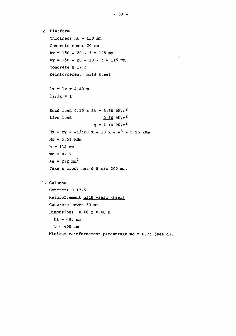
Member no . 4
safety factor
N' (kN)
M (kNm)
e = M/N' (mm)
Nd' (kN)
Ab (m2)
Nd'/Ab (N/mm2)
Nd'/Ab . e/ht
wo
Load case 1
1.7
372.08
7.41
19.91
632.54
0.16
3.95
0.196
0
load case 2
1.2
421.24
18.52
43.97
505.49
0.16
3.16
0.347
0
Member no . 7
safety factor
N' (kN)
M (kNm)
e = M/N' (nan)
Nd' (kN)
Ab (m2)
Nd'/Ab (N/mm2)
Nd'/Ab .e/ht
wo
Load case 1
1.7
420.15
10.50
25.00
714.26
0.16
4.46
0.28
0
Load case 2
1.2
527.26
21.85
41.44
632.71
0.16
3.95
0.41
0
- 35 -
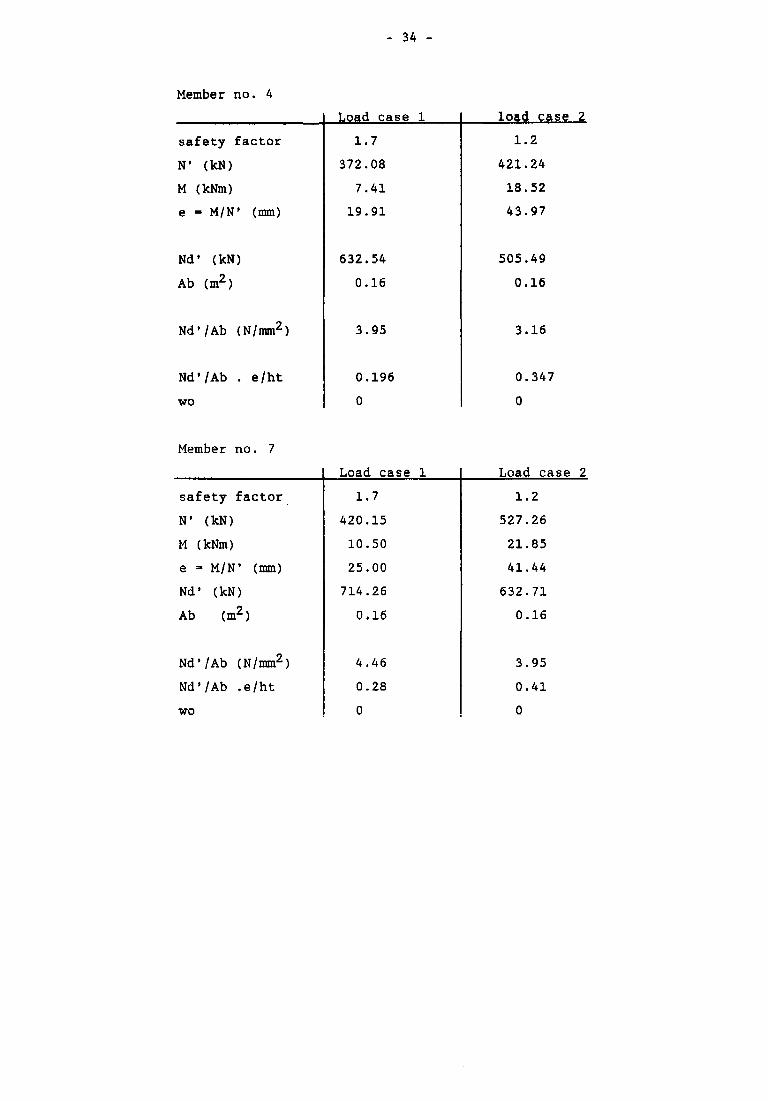
Member no . 5
safety factor
N' (kN)
M (kNm)
e - M/N1 (mm)
Nd' (kN)
Ab (m2)
Nd'/Ab (N/mm2)
Nd'/Ab. e/ht
wo
Load case 1
1.7
347.77
12.96
37.26
591.21
0.16
3.70
0.344
0
load case 2
1.2
403.03
30.75
76.30
483.64
0.16
3.02
0.58
0
Member no . 8
safety factor
N' (kN)
M (kNm)
e = M/N' (mm)
Nd1 (kN)
Ab (m2)
Nd'/Ab (N/mm2)
Nd'/Ab. e/ht
wo
load case 1
1.7
384.94
15.06
39.12
654.39
0.16
4.09
0.40
0
load case 2
1.2
484.39
32.77
67.65
581.26
0.16
3.63
0.613
0
- 36 -
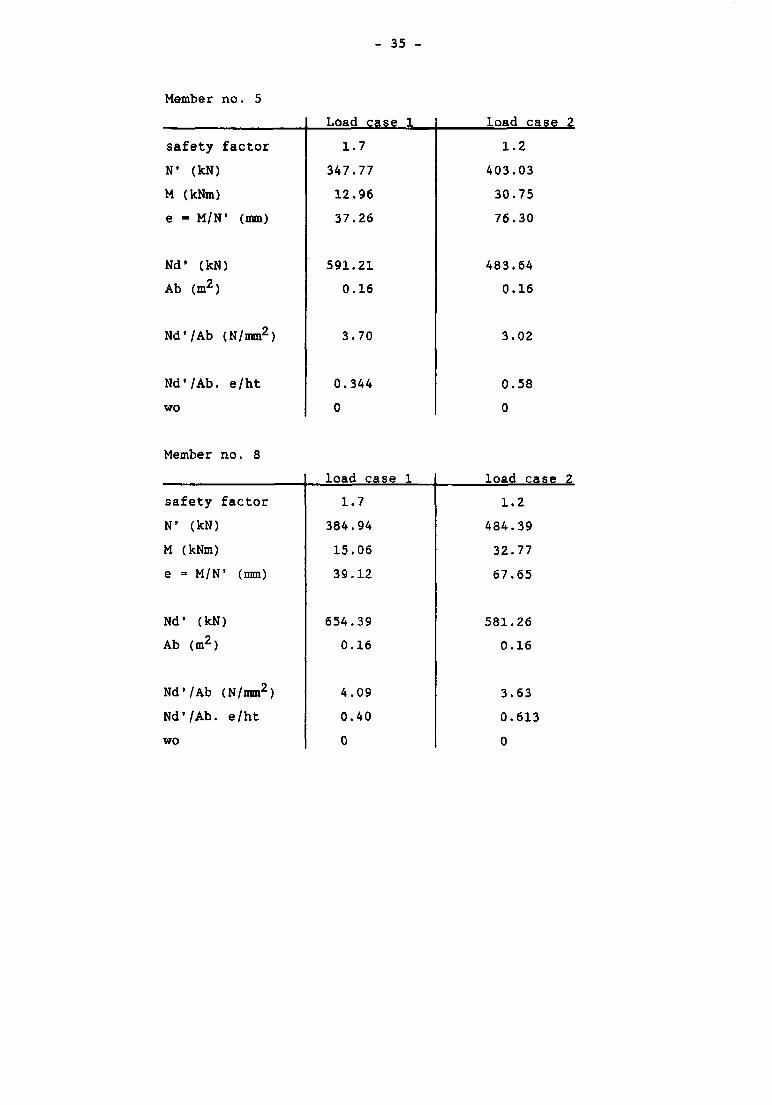
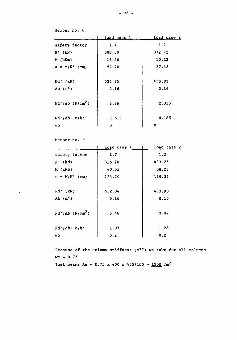
Member no. 6
safety factor
N' (kN)
M (kNm)
e - M/N' (mm)
Nd' (kN)
Ab (m2)
Nd'/Ab (N/mm2)
Nd'/Ab. e/ht
wo
load case 1
1.7
308.50
16.26
52.70
536.95
0.16
3.36
0.613
0
load case 2
1.2
372.72
10.22
27.42
453.83
0.16
2.836
0.185
0
Member no. 9
safety factor
N' (kN)
M (kNm)
e - M/N' (mm)
Nd1 (kN)
Ab (m2)
Nd'/Ab (N/mm2)
Nd'/Ab. e/ht
wo
load case 1
1.7
325.20
40.55
124.70
552.84
0.16
3.46
1.07
0.2
load case 2
1.2
403.25
68.28
169.35
483.90
0.16
3.02
1.28
0.2
Because of the column stiffness (=EI) we take for all columns
wo - 0.75
That means Aa - 0.75 x 400 x 400/100 = 1200 mm2
- 37 -
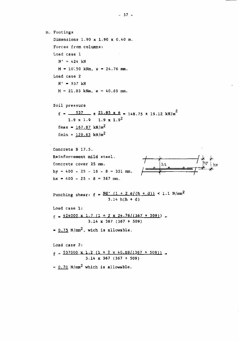
m. Footings
Dimensions 1.90 x 1.90 x 0.40 m.
Forces from columns:
Load case 1
N' = 424 kN
M - 10'. 50 kNm, e = 24.76 mm.
Load case 2
N1 = 537 kN
M = 21.85 kNm, e = 40.69 mm.
Soil pressure
f - 537 ± 21.85 x 6
1.9 x 1.9 1.9 x 1.92
fmax = 167.87 kN/m2
fmin * 129.63 kN/m2
143,75 ± 19.12
Concrete B 17.5.
Reinforcement mild steel.
Concrete cover 25 mm.
hy - 400 - 25 - 16 - 8 = 351 mm.
hx - 400 - 25 - 8 = 367 mm.
ht hv hx
Punching shear: f - Nd' ( 1 + 2 e/(h + d?) < 1.1 N/mm2
3.14 h(h + d)
Load case 1:
f m 424000 x 1.7 (1 + 2 x 24.76/(367 + 509)) =3.14 x 367 (367 + 509)
» 0.75 N/mm2, wich is allowable.
Load case 2:
f = 537000 X 1.2 f l + 2 x 40.69/(367 + 509H3.14 x 367 (367 + 509)
= 0.70 N/mm2 which is allowable.
- 38 -
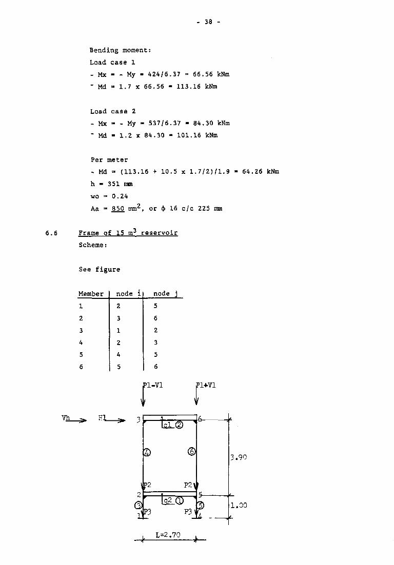
Bending moment:
Load case 1
- Mx - - My - 424/6.37 = 66.56 kNm
" Md - 1.7 X 66.56 - 113.16 kNm
Load case 2
- Mx - - My - 537/6.37 - 84.30 kNm
~ Md - 1.2 x 84.30 - 101.16 kNm
6.6
Per meter
- Md - (113.16 + 10.5 x 1.7/2J/1.9
h - 351 mm
wo = 0.24
Aa =• 850 mm^, or <j> 16 c/c 225 mm
Frame of 15 m3 reservoir
Scheme:
64.26 kNm
See figure
Member
1
2
3
4
5
6
node i
2
3
1
2
4
5
node j5
6
2
3
5
6
Pl-Vl Pl+Vl
Iql © 6-
P2l
4P3 P3^
, L=2.70
5.90
1.00
- 39 -
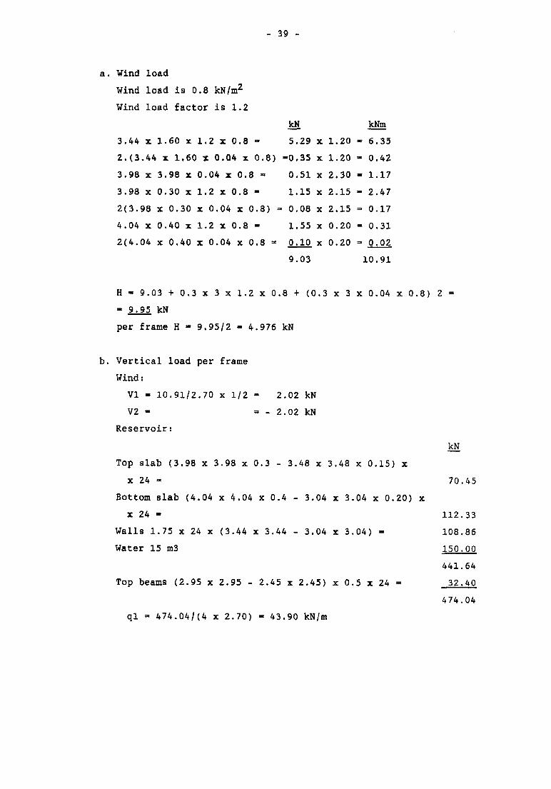
a. Wind load
Wind load is 0.8 kN/m2
Wind load factor is 1.2
kN kNm
3.44 x 1.60 x 1.2 x 0.8 - 5.29 x 1.20 - 6.35
2.(3.44 x 1.60 x 0.04 x 0.8) -0.35 x 1.20 - 0.42
3.98 x 3.98 x 0.04 x 0.8 - 0.51 x 2.30 - 1.17
3.98 x 0.30 x 1.2 x 0.8 - 1.15 x 2.15 - 2.47
2(3.98 x 0.30 x 0.04 x 0.8) = 0.08 x 2.15 = 0.17
4.04 x 0.40 x 1.2 x 0.8 - 1.55 x 0.20 - 0.31
2(4.04 x 0.40 x 0.04 x 0.8 - 0.10 x 0.20 = 0.02
9.03 10.91
H - 9.03 + 0.3 x 3 x 1.2 x 0.8 + (0.3 x 3 x 0.04 x 0.8) 2 =
- 9.95 kN
per frame H - 9.95/2 - 4.976 kN
b. Vertical load per frame
Wind:
VI - 10.91/2.70 x 1/2 - 2.02 kN
V2 - - - 2.02 kN
Reservoir:
kN
Top slab (3.98 x 3.98 x 0.3 - 3.48 x 3.48 x 0.15) x
x 24 - 70.45
Bottom slab (4.04 x 4.04 x 0.4 - 3.04 x 3.04 x 0.20) x
x 24 - 112.33
Walls 1.75 x 24 x (3.44 x 3.44 - 3.04 x 3.04) = 108.86
Water 15 m3 150.QQ
441.64
Top beams (2.95 x 2.95 - 2.45 x 2.45) x 0.5 x 24 = 32.40
474.04
ql - 474.04/(4 x 2.70) = 43.90 kN/m
- 40 -
Ground beams
q2 - 0.25 x 0.40 x 24 - 2.40 kN/m
Inclusive the weight of the columns:
PI - 1.35 x 43.90 = 59.27 kN
P2 - 1.50 x 2.40 + 3.2 x 0.3 x 24 - 10.51 kN
P 3 « 0 . 3 x 0 . 3 x l x 2 4 = 2 . 1 6 k N
Total vertical load (live load + dead load)
level + 4.90: 2 x 59.27 + 2.7 x 43.90 - 237.07 kN
level + 1.00: 2 x 10.51 + 2.7 x 2.40 - 27.50 kN
footings: 2 x 2.16 + 2(0.4 x 24 x 1.4 x 1.4) - 41.95 kN
W = 306.52 kN
c. Earthquake load
See also frame of 50 m^ reservoir.
V - ZKCW = 1 x 2.5 x 0.08504 x 306.52 = 65.17 kN
The shear force at the top is Vh - 0.15 x 65.17 » 9.775 kN.
Vx. hx - 237.07 x 4.9 + 27.51 x 1 = 1189.14 kNm
Vertical force:
Level +4.90
Fx - (65.17 - 9.775) x 237.07 x 4.9/1189.14 = 54.12 kN
Level +1.00
Fx = (65.17 - 9.775) x 27.50 x 1.00/1189.14 = 1.28 kN
So in the case of earthquake with dead load and live load:
ql - 43.90 + 54.12/5.4 =» 43.90 + 10.02 - 53.92 kN/m
q2 - 2.40 + 1.28/5.4 - 2.40 + 0.24 = 2.64 kN/m
- 41 -
PI - 59.27 + 1.35 x 10.02 = 72.80 kN
P2 - 10.51 + 1.35 x 0.24 - 10.84 kN
P3 - 2.16 kN
Vh - 9.775 kN
The safety factor for that load case is 1.2
d. Modulus of elasticity
E - modulus of elasticity
I - moment of inertia
Columns:
dimensions 0.30 x 0.30 m
assume a percentage of reinforcement wo - 0.5
E - 1/3 x (8 wo + 10) x 106= 4.66 x 10⁶ kN/m2
El - 4.66 x 106 x 1/12 x 0.34 = 3145.50 kNm2
Top beams:
dimensions 0.25 x 0.50 m
assume wo = 0.8
E = (7.5 wo + 2.5) x 106 - 8.50 x 10⁶ kN/m2
El - 8.50 x 106 x 1/2 x 0.25 x 0.503 - 22135 kNm2
Ground beams:
dimensions 0.25 x 0.40 m
assume wo - 0.5
E - (7.5 wo + 2.5) x 106 - 6.25 x 10⁶ kN/m2
El - 6.25 x 106 x 1/2 x 0.25 x 0.43 = 8333 kNm2
e. Load cases
1. dead load + live load + wind
2. dead load + live load + earthquake
f. Calculation of the member forces
See computer output at pages 1 to 6 of chapter 9.
- 42 -
g. Calculation of the second moment factor n/(n-l)
For the members no 3 and 4 the buckling length has been
calculated with a computer program - see also 6.5.g - The result
is:
for member nr. 3 Lk = 2.27 m
for member nr. 4 Lk = 4.07 m
Nk1 = 3.142 x EI/Lk2
Columns 4 and 6:
Nk1 - 3.142 x 3145.5/4.072 = 1872 kN
Columns 3 and 5:
Nk' = 3.142 x 3145.5/2.272 = 6018 kN
Load case 1:
Columns 4 and 6
Max. N' = 124.22 kN
Ndf - 1.7 x 124.22 - 211.17 kN
n - 1872/211.17 - 8.864
n/(n - 1) =• 1.127
Load case 2
Columns 4 and 6
max. N' - 152.83 kN
Nd' = 1.2 x 152.83 - 183.40 kN
n = 1872./183.4 - 10.21
n/(n - 1) - 1.108
The horizontal loads to be multiplied with 1.127 for load case 1
en with 1.108 for load case 2.
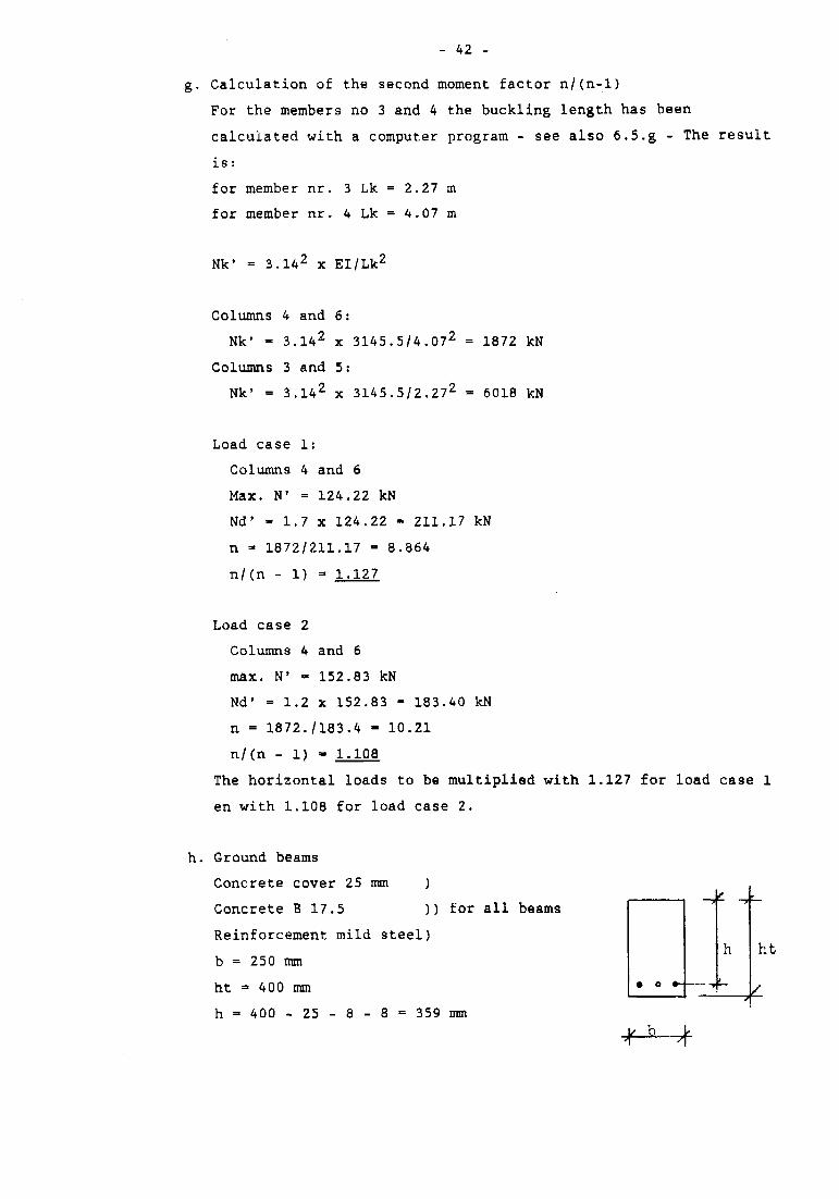
h. Ground beams
Concrete cover 25 mm )
Concrete B 17.5 )) for all beams
Reinforcement mild steel)
b = 250 mm
ht = 400 mm
h = 400 - 25 - 8 - 8 = 359 mm
h ht
- 43 -
Load case 1
Safety factor j = 1.7
+ M =* 4.02 kNm + Md = 6.834 kNm
- M = 7.40 kNm - Md - 12.58 kNm
T - 7.47 kN Td - 12.70 kN
Load case 2
Safety factor j - 1.2
+ M - 9.08 kNm + Md - 10.90 kNm
- M - 12.97 kNm - Md = 15.57 kNm
T - 11.73 kN Td - 14.08 kN
max. Md - 15.57 kNm
wo - 0.22
Aa - 201 mm2
Because of the beam stiffness (= El) we take for lower as well as
for upper reinforcement.
wo = 0.25 Aa = 225. mm2, or 2 $ 12
Shear force
Td - 14.08 kN
ft = 14080/(250 x 359) = 0.16 N/mm2
ties <|)8 c/c 250 mm (practical)
i. Top beams
b « 250 mm
ht = 500 mm
h - 500 - 25 - 8 - 8 - 459 mm
Load case 1
Safety factor j = 1.7
+ M - 35.65 kNm + Md - 60.61 kNm
- M - 9.95 kNm - Md - 16.92 kNm
T - 63.41 kN Td = 107.80 kN
- 44 -
Load case 2
Safety factor j = 1.2
+ M - 44.00 kNm
- M = 16.16 kNm
T = 80.81 kN
+ Md - 52.80 kNm
- Md = 19.39 kNm
Td = 96.97 kN
Lower reinforcement:
+ Md = 60.61 kNm
wo - 0.55
Aa = 630 mm2
Upper reinforcement:
- Md - 19.39 kNm
wo = 0.17
Aa ** 195 mm
Remark: because of the stiffness (=EI) the reinforcement is more
than calculated.
Lower reinforcement 3 c|> 16
Upper reinforcement 2 $ 16
Shear force:
Td = 107.80 kN
ft = 107800/(250 x 459) - 0.94 N/mm2
Stirrups are necessary in this case. Ast is the cross sectional
area of the stirrups per meter lenght of beam.
Ast = 5.5 (0.94 - 0.55) 250 = 536 mm2/m
Ties ()> 8 c/c 175 mm
or c|> 10 c/c 250 mm
j. Columns
Concrete B 17.5
Reinforcement: high yield steel I
Concrete cover 30 mm
Dimensions: 0.30 x 0.30 m
ht = 300 mm
b » 300 m
Minimum reinforcement percentage wo
-X-0.5 (see d)
ht
- 45 -
Member no. 4
Safety factor
N» (kN)
M (kNm)
e - M/N' (mmm)
Nd' (kN)
Ab (m2)
Nd'/Ab (N/mm2)
Nd'/Ab. e/ht
wo
load case 1
1.7
112.37
3.27
29.10
191.03
0.09
2.12
0.21
0
load case 2
1.2
137.58
7.77
56.48
165.10
0.09
1.83
0.34
0
Member no. 6
Safety factor
N' (kN)
M (kNm)
e - M/N' (mm)
Nd' (kN)
Ab (m2)
Nd'/Ab (N/mm2)
Nd'/Ab. e/ht
wo
Load case 1
1.7
124.70
9.95
79.79
212.00
0.09
2.36
0.63
0
load case 2
1.2
153.61
16.16
105.20
184.33
0.09
2.05
0.72
0
Because of the stiffness (= El) we take for all columns wo
That means Aa - 0.5 x 300 x 300/100 • 450 mm2.
0.5
- 46 -
k. Footings
Dimensions 1.40 x 1.40 x 0.40 m
Forces from columns
Load case 1:
N' - 144.84 kN
M « 2-29 kNm e - 15.81 mm
Load case 2:
N' - 178.34 kN
M - 4.46 kNm e - 25.01 mm
Soil pressure:
f - 178.34/1.4 x 1.4 ± 4.46 x 6/1.43 =
- 90.99 ± 9.75 kN/m2
Concrete B 17.5
Reinforcement: mild steel
Concrete cover 25 mm
hx - 400 - 25 - 8 - 367 mm
hy - 400 - 25.- 16 - 8 = 351 mm
Bending moment:
Load case 1
- Mx - - My - 1 4 4' 8 4 = 22.74 kNm6.37
- Md - 1.7 x 22.7'4- 38.65 kNm
Load case 2
- Mx - - My = 1 7 8- 3 4 - 28.00 kNm6.37
- Md = 1.2 x 28.00 - 33.60 kNm
Per meter:
- Md = (38.65 + 2.29 x 1.7/2)/l.4 - 29.00 kNm
hy - 351 mm = h min
wo - 0.11
Aa = 379 mm2
Take <t> 12 c/c 200 mm
- 47 -
CALCULATION OF CONCRETE MIX FOR 1 M3 OF CONCRETE
DATA:
- concrete class B17.5
- gravel maximum size 31.5 mm
- cement Portland
- watertight concrete
z = max. slump - 100 mm
For watertight concrete it is necessary to use 325 kg cement per m3
and to use not more than 175 liter water per m3 of concrete mix.
325 kg Portland cement - 325/3150 = 0.103 m3
175 liter water - 175/1000 - 0.175 m3
air 12 0.010 m 3
0.288 m3
rest for sand + gravel
1.00 - 0.288 - 0.712 m3
To calculate the percentage of sand we use the formula
Pz = 10 Fz + 28 + 0.05z - 0.08 C
Fz = 3
Pz = 10 x 3 + 28 + 0.05 x 100 - 0.08 x 325= 37Z
sand 37/100 x 0.712 - 0.263 m3
gravel 63/100 x 0.712 - 0.449 m3
sand 0.263 x 2650 = 697 kg
gravel 0.449 x 2650 =• 1190 kg.
Concrete mix for 1 m3 of concrete:
- Portland cement 325 kg
- water 175 liter
sand 697 kg
- gravel 1190 kg

- 49 -
8. TABLES AND CHARTS
Collection of tables and charts from the Dutch Standards used with
the calculation of the water reservoirs.
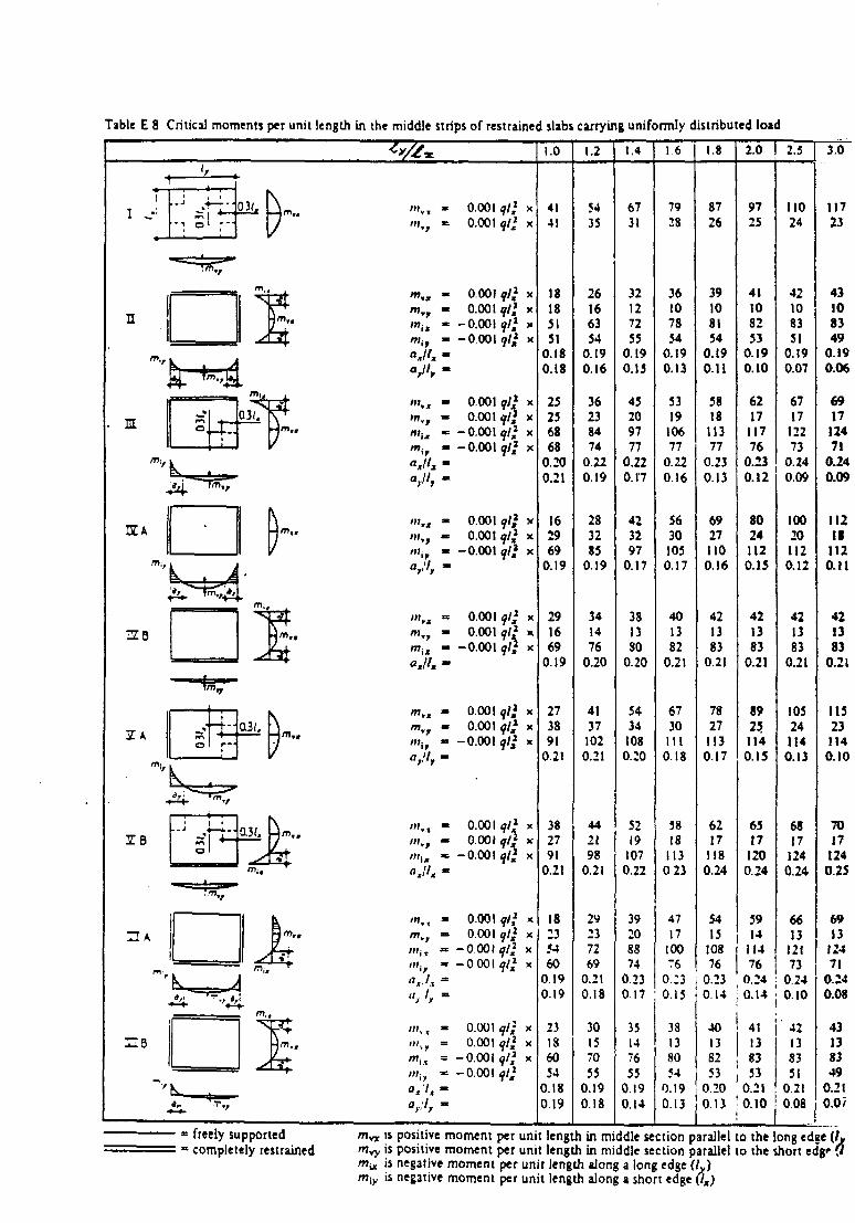
Table E 8 Critical moments per unit length in the middle strips of restrained slabs carrying uniformly distributed load
1.0 1.2 1.4 1.6 1.8 2.0 I 2.5 | 3.0
m
mim
arll,
IA' " i ,
arl,
0.001 qt* x0.001 ql} x
0,001 ql} x0.001 ql} x
-0.001 ?/,» x-0.001 t}t* x
0.001 9/* x0.001 qll x
-O.OOI9/,1 x-0.001 ql* x
0.001 y/,1 x0.001 qt* x
-0.001^// x
0.0010.001
-0.001
0.001 f/,1 x0.00\ ql* x
-0.001 f / i x
0.001 ql} x0.001 ql} x
-0.001 ql} x
0.001 ql* x0.001 qlj x
•0001 9/i x•0001 qtf x
0.001 ql} x0.001 ? / i x
-0.001 ql} x-0.001 ql}
4141
18183151
0.180.18
25256868
0.200.21
162969
0.19
291669
0.19
273891
0.21
382791
0.21
18:35460
0.190.19
23186054
0.180.19
5435
26166354
0.190.16
36238474
0.220.19
283285
0.19
341476
0.20
41371020.21
442198
0.21
29237269
0.210.18
30157055
0.190.18
6731
32127255
0.190.15
45209777
0.220.17
423297
0.17
381380
0.20
5434108o.;o
5219
1070.22
39208874
0.230.17
35147655
0.190.14
7928
36107854
0.190.13
5319
10677
0.220.16
5630105
0.17
401382
0.21
67301110 18
5818
1130 23
4717
100"6
38138054
0.19
8726
39108154
0.190.11
3818
11377
0.230.13
6927110
0.16
421383
0.21
7827113
0.17
6217
1180.24
5415
10876
9725
41108253
0.190.10
6217
11776
0.230.12
80241120.15
421383
0.21
8925.1140.15
6517
1200.24
5914
11476
0.23 ; 0.23 \ 0.24 j 0.240 15 I 0.14 ; 0.14 j 0.10
401382 ! 8353 53
0.20 0.210.13 ] 0.13 '0.10
41 i 4213 ! 13
8351
0.21008
= freely supported; • completely restrained
m ^ is positive moment per unit length in middle section parallel to the long edge (/»m^y is positive moment per unit length in middle section parallel to the short edg' 0ffiu is negative moment per unit length along a long edge (L)miy is negative moment per unit length along a short edge Ox)
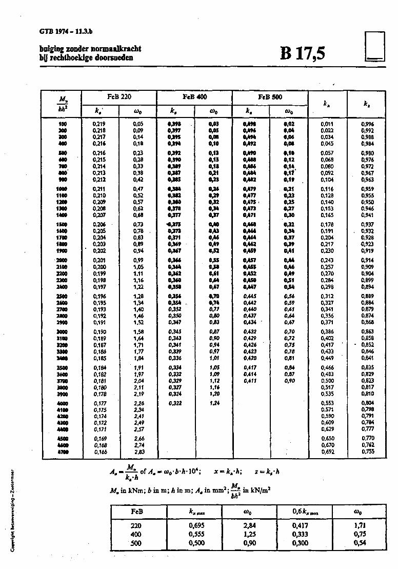
GTB1974-11.3.b
bulging zonder nonnaalkrachtby rechthoekige doorsoeden B17,5
bh*
100200MO«00
tooMO700•00900
10001100120013001*00
1100MM170011001*00
20002100220023002400
25002M0270028002900
30003100320033003400
3500WOO370038003900
40004100420041004400
45004*M47M
FcB
*. '
0.2190,2180,2170,216
0,2160,2150,2140,2130,212
0.2110,2100,2090,2080,207
0,2060.2050.2040.203
" 0,202
0.2010,2000.1990,1980.197
0,1960,1950,1930.1920.191
0.1900,1890.1870.1B60,185
0,1840.1820.1610.1800.178
0,1770,1750.1740.1720.171
0,1690,1680.166
220
w0
0,050,090.140.18
0,230,260.330,380,42
0.470,520.570,620,68
0,730,780,830,890,94
0,991.051.111.161.22
1.281.341.401.461.52
1.581.641.711,771.84
1.911.972,042,112,19
2,262,342,412,492.57
2.662,742.83
FeB
cm0,3*70,3958,394
0,3920390•389•3*7•385
•384•3*2•300•378•377
<jm•373•371• 3 »0,347
•3M0364•3620360•358
035603540,352OJSO0,347
0.34503430,3416,3390336
03340.33203290.3270.324
0^22
400
O)0
0330350,080,10
0.13«.«0.18031033
•3603*032034037ObM033*M039031
•350380,61tjbk0^7
0,700,740.770,800JB3
OJBJ0,900,940,971.01
1.051.091.121.161.20
U4
FeB
* .
0,*9t0,4960^940,492
0,4900,4880,4860,4849/ka0,4790,4770,47$.0,4730,471
0,468CM*0,46403620,459
0,4570,4550,4520^50OVM7
0.4450,4420,4400,4370,454
0,4320,4290,4260,4230,420
O.4T70,4140,411
500
o>o
0,020,040,060,08
0,100,12
«.»*.0.170,19
031033035037030
03203*0370390,41
0.440,460^9031034
0360J90.610.640.67
0,700,720.7S0.700,61
0340,870,90
K
0,0110.0220,0340,045
0.0570,0680,0800,0920.104
0.1160,1280.1400.1530.165
0.1780.1910,2040.2170,230
0.2430,2570,2700,2840,296
0,3120,3270.3410.3560.371
0,3860,4020,417 •0.4330,449
0.4660.4830,5000.5170.535
0,5530,5710,5900,6090,629
0,6500.6700,692
0.9960,9920.9680,984
0,9800.9760.9720.9670,963
0,9590,9550,9500.9460,941
0.9370.9320,9280,9230.919
0,9140,9090,9040.8990,894
0,8890.8840.6790.8740.868
0,8630.858
• O.8S20,6460,641
0,8350,8290.8230,8170.B10
0,8040.7980,7910.7840,777
0.7700.7620,755
MMm in kNm; b in m; h in m; A. in mm2; —~ in kN/m2
bhFeB
220400500
0,6950,5550,500
O)0
2,841,250,90
OfikKmtt
0,4170,3330,300
to0
1.710,750.54
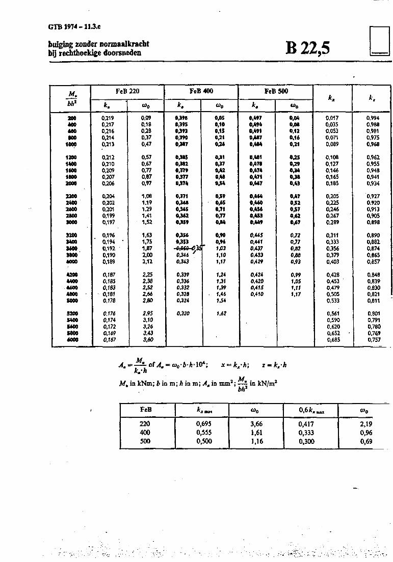
GTB 1974 - I1.3.C
buigiog zonder nonnaalkracbtby recbthoekige dooreneden B22,5
bh*
2M400MOMO
1000
12001400160018002000
22002400260028003000
32003400360038004000
42004400460048005000
520054005600S800MOO
FeB
* .
0,2190,2170,2160,2140.213
0.2120,2100,2090.2070.206
0.2040,2020,2010,1990.197
0,1960.194 •0.1920,1900.189
0.1870.1850.183
-0,1810.178
0.1760,1740.1720,1690.167
220
Wo
0.090.180.280,370,47
0,570,670,770,870.97
1,081,191.291.411.52
1,631.751,872,002,12
2.252,382£22,662,60
2,953.103.263.433,60
FeB 400
k.
0,3980,39504930,3900,387
0^8504820,37904770474
0,37104680,36504620459
045604530,0*0 tfii0.346 '0,343
0,3390,3360.3320,3200,324
0,320
(00
0,050,100,150,210,26
0410470,420,M044
0490,650,710.77044
0,900,961.031,101,17
V41*11*91,461.54
1,62
FeB
k.
0,4970,4940,4910,4870,484
0,4810,4780,4740,4710,467
0,4640,4600,4560,4530,449
0,4450,4410,4370.4330,429
0.4240,4200,4150,410
500
w0
0,040,080,120.160,21
0,250,291>4411480,43
0,470.520,570,620,67
0.720.770,820,680,93
0,991.051.111,17
K
0.0170,0350,0530,0710,089
0,1080.1270,1460,1650,185
0,2050.2250.2460,2670.289
0,3110,3330,3560.3790,403
0,4280,4530.4790.5050.533
0,5610,5900,6200.652 •0.685
0.9940.9880.9810.9750,968
0,9620.9550.9480,9410.934
0.9270,9200,9130,9050,898
0.8900.8820,8740,8650.857
0.8480.8390,8300,8210,811
0,8010,7910,7800,7690,757
Mu in kNm; b\nm;h in m; Am in mm1; —~ in JcN/m2
bh
FeB
220400500
0,6950,5550,500
3,661,611,16
OfikXBM
0,4170,3330,300
©o
2,190,960,69
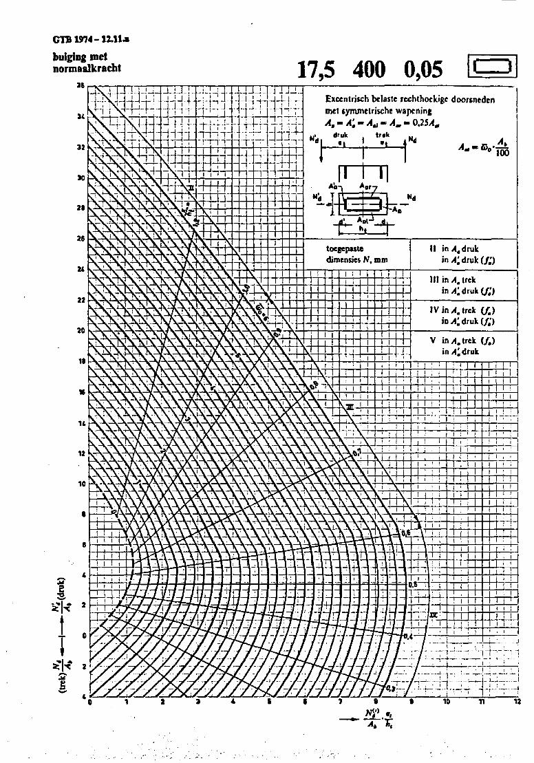
GTB1974-1Z.1U
bulging metnormaalkracht 17,5 400 0,05
Excentrisch belaste rechthockige doortnedcnmet tymmetrische wapenjng
trak
tocgepastediroensies N, mm
IV in A. trek (/.)
V in A, trek (/.)inyfidruk
GTB 1974-12.1 l.b
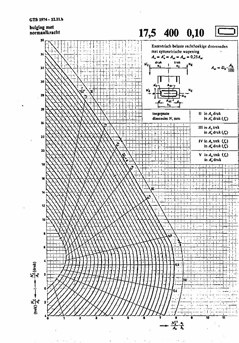
bulging metnormaalkracht 17,5 400 0,10
Excentri&ch belaste rechthoelcigc doorsncdcnmet symmctrische wapeningA, - A'. - A., -A^- 0,25/4
druh tr*k
I! in A. drukin/Cdruk(/.')
tocgepastedimensies N, mm
IV in At trek (J.)iny4;druk(/.')
V in A, trek (/.)in 4 druk
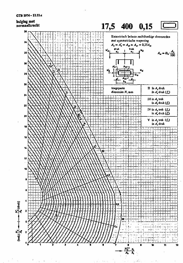
GTB1974-12.H.C
bulging metDormaalkracht
IB17,5 400 0,15
-fcs^rtocgeputedinaensies N, mm
Exccntrisch bclaste rcchthoekige doorsncdcnmet symmetrische wapcningA.-A't- A* « Av - 0,25,4,,
druk . trakAk
I I
I ' M
i iM i
i i
II in/l.druk
III in A, trek
IV in A, trek (/,)
V hA.Xnkin^druk
i : i i I : i i
I ! !
I I iI i !
i I
TTT! ' i i
I I M
- M -
_Li_L
i i II i
T T
T TU
' ITI ! !
I i Mill ' i i
-1-1-T; i
J_i_
I ITTM
M
I I i i
' I M
TTT-n-f-n~rrn
I I !! I T
J !I 1 I
I ' iI I
TTTI 1
n i i
TTTT
I i
•i-i--;: T !._:..i
4 A,
10 11 12
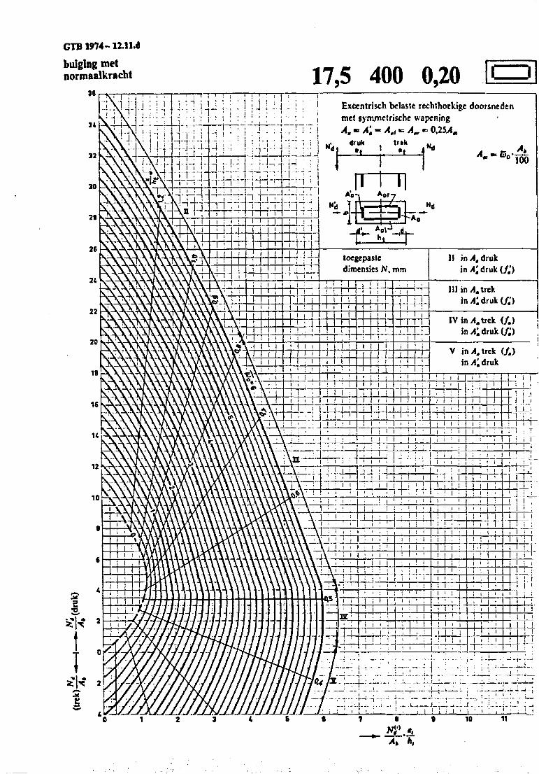
GTB 1974- 12.II.d
bulging metnorinaalkracht 17,5 400 0,20
Excentrisch bclaste rechthoekige doorsnedenmet synunetrische wapeningA, - A', - A.t ~AV
"d.druk
Itrtk
-*>-vk
A'o
f"tocgepastedimensics N, mm
n
i i
I I I
1! in>4, druk
III in A. trek
IV in A. trek (/.)
I ! I
V in >l. trek (/.)in A', druk
MM t i !I ' I
—r—i 1-
1 I 1 > i !
; I ' I
-H- I I
Mil
I [ i •• I TM | i :
! I I
I I ! : i
MMi IT
I ' l l
I ; I
tTTi'i ; ' i •MMMM"
i I j i1 f
T T
I I
Mr i
- 57 -
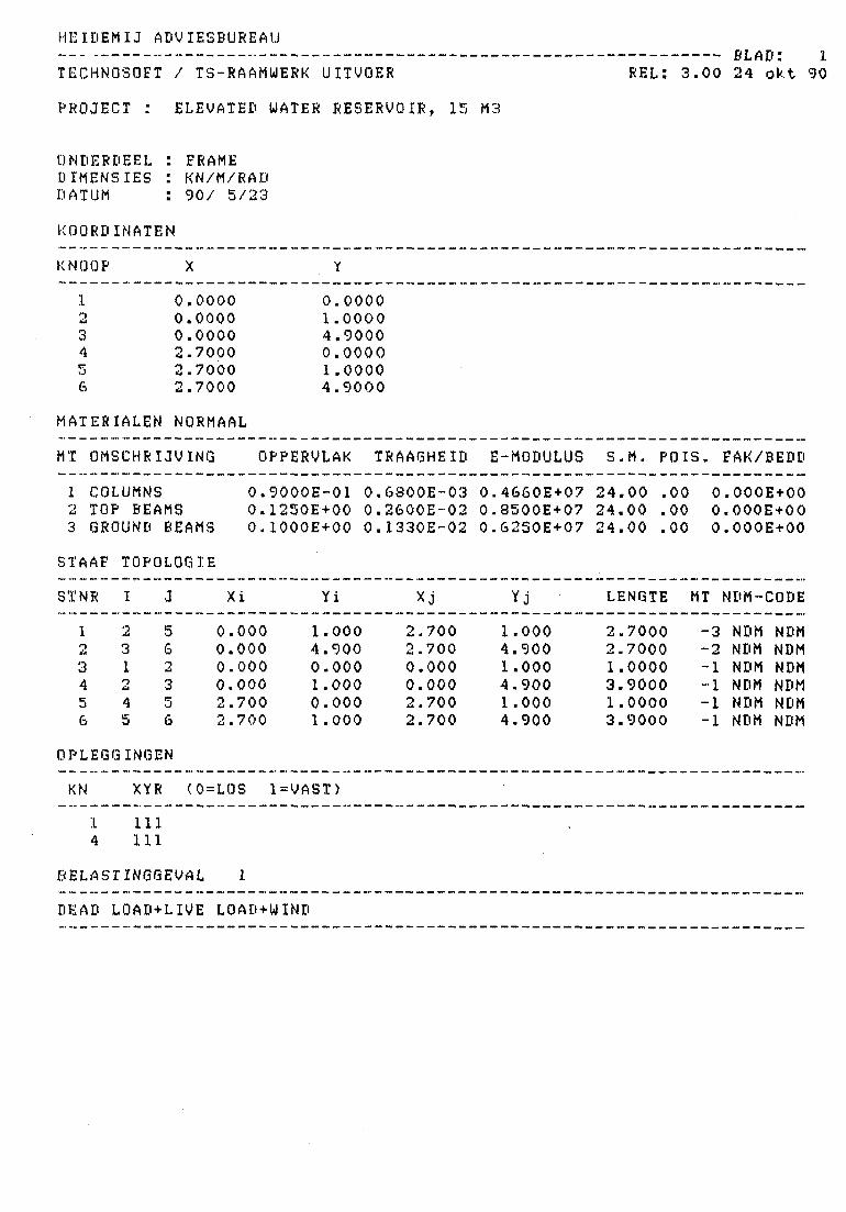
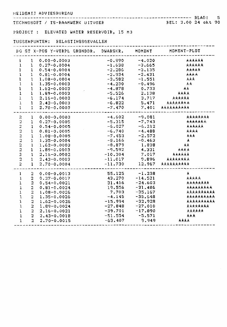
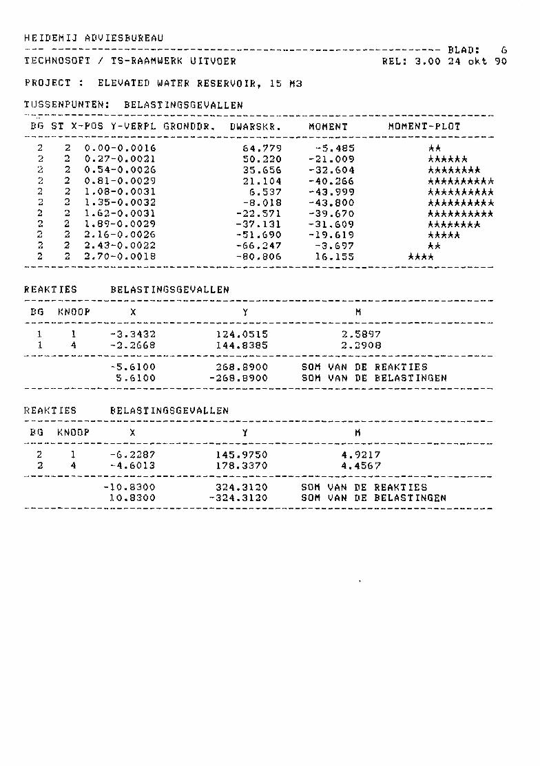
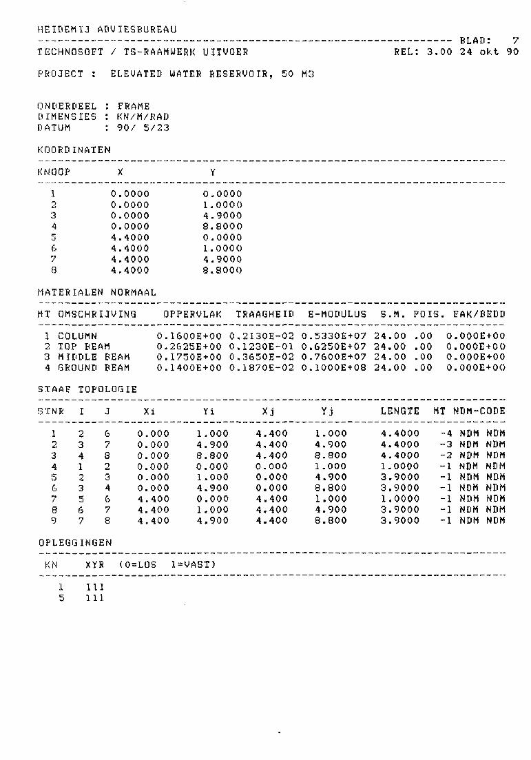
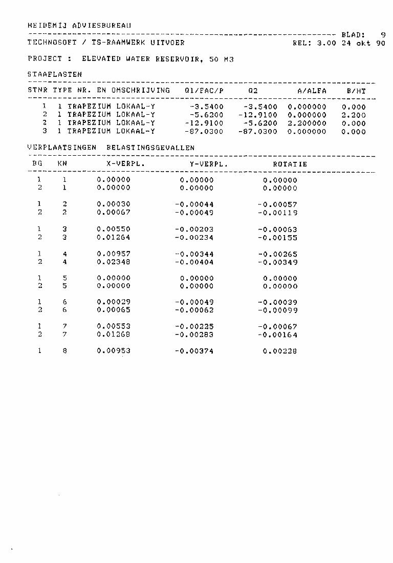
9. COMPUTER OUTPUT
Computer calculations of the frames for the IS m3 and 50 m3
elevated water reservoirs.
HE IDEM IJ ADVIESBUREAU
TECHNOSOET / TS-RAAMUERK UITVOER
PROJECT : ELEVATED WATER RESERVOIR, 15 M3
BLAD: .1.REL: 3 . 0 0 24 o k t 90
ONDERDEELDIMENSIESDATUM
FRAMEKN/M/RAO90/ 5/23
KOORDINATEN
KNOOP
123456
0.00000.00000.00002.70002.70002.7000
0.00001.00004.90000.00001.00004.9000
MATERIALEN NORMAAL
MT OMSCHRIJVING OPPERVLAK TRAAGHEID E-MODULUS S.M. POIS. FAK/BEDD
1 COLUMNS2 TOP BEAMS
3 GROUND BEAMS
STAAF TOPOLOGIE
STNR I J Xi
0.9000E-01 0.6800E-03 0.4660E+07 24.00 .00 O.OOOE+000.1250E+00 0.2600E-02 0.8500E+07 24.00 .00 O.OOOE+000.1000E+00 0.1330E-02 0.6250E+07 24.00 .00 O.OOOE+00
Yi LENGTE MT NDM-CODE
123456
231245
562356
0.0000.0000.0000.0002.7002.700
1.0004.9000.0001.0000.0001.000
2.7002.7000.0000.0002.7002.700
1.0004.9001.0004.9001 .0004.900
2.70002.70001.00003.90001.00003.9000
-3-2-1
"I"I
NDMNDMNDMNDMNDMNDM
NDMNDMNDMNDMNDMNDM
OPLEGGINGEN
KN XYR <O=LQS 1=VAST)
14
111111
BELASTINGGEVAL 1
DEAD LOAD+LIVE LOAD+UIND
HEIDEMIJ ADVIESBUREAU
TECHNQSQFT / TS-RAAMUERK UITVOER
PROJECT : ELEVATED WATER RESERVOIR, 15 M3
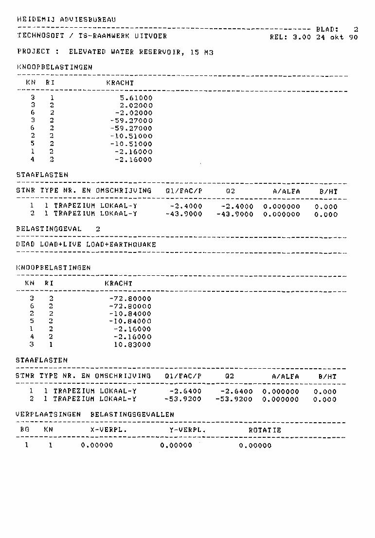
KNOOPBELASTINGEN
REL: 3 . 0 0 24 o k t 90
KN RI
3 13 26 23 26 22 25 21 24 2
STAAFLASTEN
STNR TYPE NR.
1 1 TRAPEZ2 1 TRAPEZ
BELASTINGGEVAL
DEAD LOAD+LIVE
KRACHT
5.610002.02000-2.02000
-59.27000-59.27000-10.51000-10.51000-2.16000-2.16000
EN OMSCHRIjgiNG
IUM LOKAAL-YIUM LOKAAL-Y
2
LOAD+EARTHQUAKE
KNOOPBELASTINGEN
KN RI
3 26 22 25 21 24 23 1
STAAFLASTEN
STNR TYPE NR.
1 1 TRAPEZ2 1 TRAPEZ
UERPLAATSINGEN
BQ
1
KN
1
KRACHT
-72.80000-72.80000-10.84000-10.84000-2.16000-2.1600010.83000
EN OMSCHRIJVING
Ql/FAC/P
-2.4000-43.9000
Ql/FAC/P
IUM LOKAAL-Y -2.6400IUM LOKAAL-Y -53.9200
BELASTINGSGEVALLEN
X-VERPL.
0.00000
Y-VERPL.
0.00000
Q2
-2.4000 0.-43.9000 0.
Q2
-2.6400 0.-53.9200 0.
ROTAT
0.00000
A/ALFA
000000000000
A/ALFA
000000000000
IE
B/HT
0.0000.000
B/HT
0.0000.000
HE IDEM IJ ADVIESBUREAUrtW^w^«____»_»_ __________„_ __ _ _ _ _ „ -« * «,-«-_-* -_ — — — .».-_.— _ _ — — — — — _ _ Df Afl • O
C> L n 1* i J
TECHNOSOFT / TS-RAAMWERK UITVOER REL: 3.00 24 okt 90
PROJECT : ELEVATED WATER RESERVOIR, 15 M3
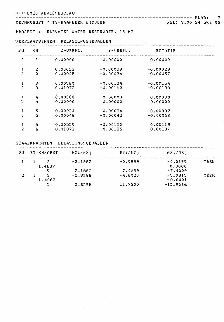
VERPLAATSINGEN BELASTINGSGEVALLEN
BG KN X-VERPL. Y-VERPL. ROTATIE
2 1 0.00000 0.00000 0.00000
1 2 0.00023 -0.00029 -0.000292 2 0.00045 -0.00034 -0.000571 3 0.00560 -0.00134 -0.001542 3 0.01072 -0.00162 -0.00198
1 4 0.00000 0.00000 0.000002 4 0.00000 0.00000 0.00000
1 5 0.00024 -0.00034 -0.000372 5 0.00046 -0.00042 -0.00068
1 6 0.00559 -0.00150 0.001192 6 0.01071 -0.00185 0.00137
STAAFKRACHTEN BELASTINGSGEVALLEN
BG ST KN/AEST NXi/NXj DYi/DYj
-0.9899
7.4699-4.6020
11.7300
MXi/MXj
1 11.4637
52
1.40625
-2.1882
2.1882-2.8288
2.8288
-4.01990.0000-7.4009-9.0815-0.0001-12.9666
TREK
TREK
HE IDEM IJ ADUIESBUREAU_. . ___. _ „__„ .„ _ _ „ „ _ __ _, _ _ _ __„____„„___„ DTAtt" A
_ ., _ _ _ _ ___ _ _ — _ „ _ -" t> L H U • *t
TECHNOSOFT / TS-RAAMUERK UITVOER REL: 3.00 24 okt 90
PROJECT : ELEVATED WATER RESERVOIR, 15 M3
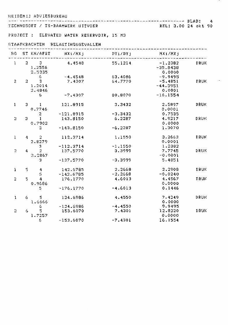
J3TAAFKRACHTEN BELASTINGSGEVALLENBG ST KN/AFST NXi/NXj DYi/DYj MXi/MXj
1 2 3 4.4548 55.1214 -1.2382 DRUK1.2556 -35.84382.5335 0.0000
6 -4.4548 63.4086 -9.94952 2 3 7.4307 64.7770 -5.4851 DRUK
1.2014 -44.39512.4846 0.0001
6 -7.4307 80.8070 -16.1554
1 3 1 121.8915 3.3432 2.5897 DRUK0.7746 0.0001
2 -121.8915 -3.3432 0.75352 3 1 143.8150 6.2287 4.9217 DRUK
0.7902 0.00002 -143.8150 -6.2287 1.3070
1 4 2 112.3714 1.1550 3.2663 DRUK2.8279 0.0001
3 -112.3714 -1.1550 1.23822 4 2 137.5770 3.3999 7.7745 DRUK
2.2867 -0.00013 -137.5770 -3.3999 5.4851
1 5 4 142.6785 2.2668 2.2908 DRUK5 -142.6785 -2.2668 -0.0240
2 5 4 176.1770 4.6013 4.4567 DRUK0.9686 0.0000
5 -176.1770 -4.6013 0.1446
1 6 5 124.6986 4.4550 7.4249 DRUK1.6666 0.0000
6 -124.6986 -4.4550 9.94952 6 5 153.6070 7.4301 12.8220 DRUK
1.7257 0.00006 -153.6070 -7.4301 16.1554
HE IDEM IJ ADVIESBUREAU
TECHNOSOFT / TS-RAAMUERK UITVOERD Ju H U • \J
REL: 3.00 24 okt 90
PROJECT : ELEVATED UATER RESERVOIR, 15 M3
TUSSENPUNTEN: BELASTINGSGEVALLEN
BG ST X-POS Y-VERPL GRONDDR, DWARSKR. MOMENT MOMENT-PLOT
111I1111111
11111111111
0.00-0.27-0.54-0.81-
08-35-62-89-
2.16-2.43-2.70-
0.00030.00040.00040.00040.00040.00030.00030.00030.00030.00030.0003
-0.990 -4.020 AAAAAA-1.638 -3.665 AAAAAA-2.286 -3.135 AAAAA-2.934 -2.431 AAAA-3.582 -1.551 AAA-4.230 -0.496 A*-4.878 0.733 AA-5.526 2.138 AAAA-6.174 3.717 AAAAAA-6.822 5.471 AAAAAAAA-7.470 7.401 AAAAAAAAAA
'•)
lit
2
11111111111
0.00-0.27-0.54-0.81-,08-,35-,62-,89-
2.16-2.43-2.70-
0.00030.00050.00050.00050.00050.00040.00030.00030.00020.00030.0004
-4.602 -9.081 AAAAAAAA-5.315 -7.743 AAAAAA*-6.027 -6.212 AAAAAA-6.740 -4.488 AAAA-7.453 -2.572 AAA-8.166 -0.463 A-8.879 1.838 AA-9.592 4.331 AAAA•10.304 7.017 AAAAAA•11.017 9.896 AAAAAAAA•11.730 12.967 AAAAAAAAAA
11111111111
2222
0.00-0.27-0.54-0.81-
08-,35-,62-,89-
2.16-2.43-2.70-
0.00130.00170.00210.00240.00260.00260.00260.00240.00210.00180.0015
55.12543.27031.41619.5567.703
-4.145-15.994-27.848-39.701•51.554-63.407
-1 .23814.521
•24.603•31.486•35.167•35.648-32.928•27.010-17.890-5 .571
9.949
AAAAAAAAAAAAAAAAAAAAAAAAAAAAAAAAAAAAAAAAAAAAAAAAAAAAAAAAAAAAAAAAAAAAAA
AAAA
HE IDEM IJ ADVIESBUREAU
TECHNOSOFT / TS-RAAMUERK UITVOER
PROJECT : ELEVATED WATER RESERVOIR, 15 M3
TUSSENPUNTEN: BELAST INGSGEVALLEN
EG ST X-POS Y-VERPL GRONDDR. DWARSKR. MOMENT
BLAD: 6REL: 3.00 24 okt 90
MOMENT-PLOT
to
22
2222
22
2
toto
222
toto
to
2
to
0.00-0.00160.27-0.00210.54-0.00260.81-0.00291.08-0.00311.35-0.00321.62-0.00311.89-0.00292.16-0.00262.43-0.00222.70-0.0018
64.77950.22035.65621.1046.537
-8.018-22.571-37.131•51.690-66.247•80,806
-5.485-21.009-32.604-40.266-43.999-43.800-39.670-31.609-19.619
-3.69716.155
AAAAAAAAAAAAAAAAAAAAAAAAAAAAAAAAAAAAAAAAAAAAAAAAAAAAAAAAAAAAAAAAAAAAAAA
AAAA
REAKT
BG
11
REAKT
BG
22
IES
KNOOP
14
IES
KNOOP
14
BELASTINGSGEVALLEN
X
-3.3432-2.2668
-5.61005.6100
Y
124.0515144.8385
268.8900-268.8900
BELASTINGSGEVALLEN
X
-6.2287-4.6013
-10.830010.8300
Y
145.9750178.3370
324.3120-324.3120
SOMSOM
SOMSOM
22
VANVAN
44
VANVAN
M
.5897
.2908
DE REAKTIESDE BELASTINGEN
M
.9217
.4567
DE REAKTIESDE BELASTINGEN
HE IDEM IJ ADVIESBUREAU
TECHNOSOFT / TS-RAAMUERK UITVOER
PROJECT : ELEVATED WATER RESERVOIR, 50 M3
BLAD: 7REL: 3 . 0 0 24 o k t 90
ONDERDEEL : FRAMEOIMENSIES ". KN/M/RADDATUM : 90/ 5/23
KOORDINATEN
KNQQP
1'3345673
0.00000.00000.00000.00004.40004.40004.40004.4000
0.00001.00004.90008.80000.00001.00004.90008.8000
MATERIALEN NORMAAL
MX OMSCHRIJVING QPPERVLAK TRAAGHEID E-MODULUS S.M. POIS. FAK/BEDD
1 COLUMN2 TOP BEAM3 MIDDLE BEAM4 GROUND BEAM
BTAAF TOPOLOGIE
0.1600E+00 0.2130E-02 0.5330E+07 24.00 .00 O.OOOE+000.2625E+00 0.1230E-G1 0.6250E+07 24.00 .00 O.OOOE+000.1750E+00 0.3650E-02 0.7600E+07 24.00 .00 O.OOOE+000.1400E+00 0.1870E-02 0.1000E+08 24.00 .00 O.OOOE+00
STNR Xi Yi LENGTE MT NDM-CODE
1
3456789
234123S67
678234678
0.0000.0000.0000.0000.0000.0004.4004.4004.400
1.0004.9008.8000.0001.0004.9000.0001 .0004.900
4.4004.4004.4000.0000.0000.0004.4004.4004.400
1.0004.9008.8001.0004.9008.8001.0004.9008.800
4.40004.40004.40001.00003.90003.90001.00003.90003.9000
-4
«• 1
-1-1-1**. I
~~ "I
NDMNDMNDMNDMNDMNDMNDMNDMNDM
NDMNDMNDMNDMNDMNDMNDMNDMNDM
OPLEGGINGEN
KN XYR <O=LOS 1=VAST)
1 111111

HE IDEM IJ ADVIESBUREAU
TECHNOSOFT / TS-RAAMWERK UITVOER
PROJECT : ELEVATED UATER RESERVOIR, 5 0 M3
BELASTINGGEVAL 1
. — w.__w.~~. — _ B L A D • 8
REL: 3 . 0 0 24 o k t 90
DEAD LQAD+LIYE LOAD+WIND
KNOOPBELASTINGEN
KN
448483372615
RI
12&221222222
STAAFLASTEN
STNR
1223
TYPE NR. EN C
1 TRAPEZIUM1 TRAPEZIUM1 TRAPEZIUM1 TRAPEZIUM
BELASTINGGEVAL '<
DEAD
KRACHT
11.080002.83000-2.83000
-160.73999-160.73999
2.80000-32.24000-32.24000-22.37000-22.37000-3.84000-3.84000
3MSCHRIJVING
LOKAAL-YLQKAAL-YLOKAAL-YLOKAAL-Y
I
LOAD+LIVE LOAD+EARTH QUAKE
KNOOPBELASTINGEN
KN RI KRACHT
Ql/FAC/P
-3.3600-4.2000
-11.4900-70.9600
Q2
-3.3600-11.4900-4.2000
-70.9600
0020
A/ALFA
.000000
.000000
.200000
.000000
B/HT
0.0002.2000.0000.000
448372615
1222222*>*ii2
31.09000-196.52000-196.52000-35.34000-35.34000-22.75000-22.75000-3.84000-3.84000
HE IDEM IJ ADVIESBUREAU
TECHNOSOFT / TS-RAAMUERK UITVOER REL: 3.00 24 okt 90
PROJECT : ELEVATED WATER RESERVOIR, 50 M3
STAAFLASTEN
STNR TYPE NR. EN OMSCHRIJVING Ql/FAC/P Q2 A/ALFA B/HT
1 1 TRAPEZIUM LOKAAL-Y -3.5400 -3.5400 0.000000 0.0002 1 TRAPEZIUM LOKAAL-Y -5.&200 -12.9100 0.000000 2.2002 1 TRAPEZIUM LOKAAL-Y -12.9100 -5.6200 2.200000 0.0003 1 TRAPEZIUM LOKAAL-Y -87.0300 -87.0300 0.000000 0.000
VERPLAATSINGEN BELAST INGSGEVALLEN
BG KN X-VERPL. Y-VERPL. ROTATIE
1 1 0.00000 0.00000 0.000002 1 0.00000 0.00000 0.00000
1 2 0.00030 -0.00044 -0.000572 2 0.00067 -0.00049 -0.00119
1 3 0.00550 -0.00203 -0.000632 3 0.01264 -0.00234 -0.00155
1 4 0.00957 -0.00344 -0.002652 4 0.02348 -0.00404 -0.00349
1 5 0.00000 0.00000 0.000002 5 0.00000 0.00000 0.00000
1 6 0.00029 -0.00049 -0.000392 6 0.00065 -0.00062 -0.00099
1 7 0.00553 -0.00225 -0.000672 7 0.01268 -0.00283 -0.00164
1 8 0.00953 -0.00374 0.00228
HEIDEMIJ ADVIESBUREAU__ _„-««,«.- ».„ *. _*.** _ — — _ — _ __™ ^ __ _ _ »~ _ _ — — _ _ DI A Tl * 1/^
" ™ • — — —"" -" -" — — ~ "*" *•* — -* D L Hi 1 • 4. \f
TECHNOSOFT / TS-RAAMWERK UITVOER REL: 3.00 24 okt 90
PROJECT : ELEVATED WATER RESERVOIR, 50 M3
VERPLAATSINGEN BELAST INGSGEVALLEN
BG KN X-VERPL. Y-VERPL. ROTATIE
2 8 0.02340 -0.00468 0.00256
STAAFKRACHTEN BELASTINQSGEVALLEN
BQ ST KN/AFST NXi/NXj DYi/DYj MXi/MXj
.1. 1 2 4.7773 1.9403 -7.3433 DRUK0.5775 -7.90352.7465 0.0001
6 -4.7773 12.8437 -16.64422 1 2 5.2310 -4.5458 -22.2532 DRUK
2.4870 0.00006 -5.2310 20.1218 -32.0153
1 2 3 -9.0390 7.0248 -8.1507 TREK1.1505 -12.61202.7677 0.0000
7 9.0890 27.4932 -36.87982 2 3 -12.9055 -5.0255 -38.9091 TREK
2.5063 0.00007 12.9055 45.7915 -72.8883
1 3 4 16.4021 150.5903 16.2590 DRUK0.1109 0.00002.1222 -143.53134.1335 0.0000
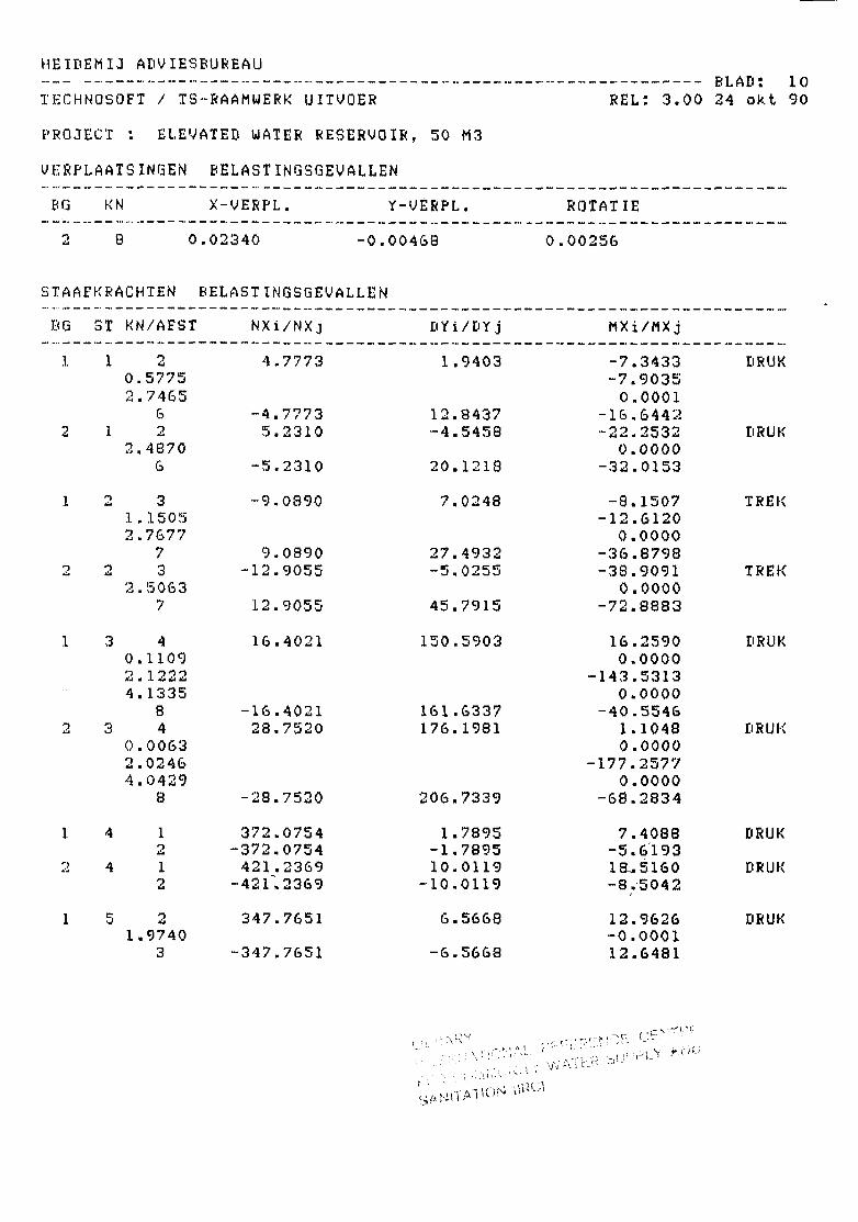
8 -16.4021 161.6337 -40.55462 3 4 28.7520 176.1981 1.1048 DRUK
0.0063 0.00002.0246 -177.25774.0429 0.0000
8 -28.7520 206.7339 -68.2834
1 4 1 372.0754 1.7895 7.4088 DRUK2 -372.0754 -1.7895 -5.6193
2 4 1 421.2369 10.0119 18,-5160 DRUK2 "421".2369 -10.0119 -8.5042
1 5 2 347.7651 6.5668 12.9626 DRUK1.9740 -0.0001
3 -347.7651 -6.5668 12.6481
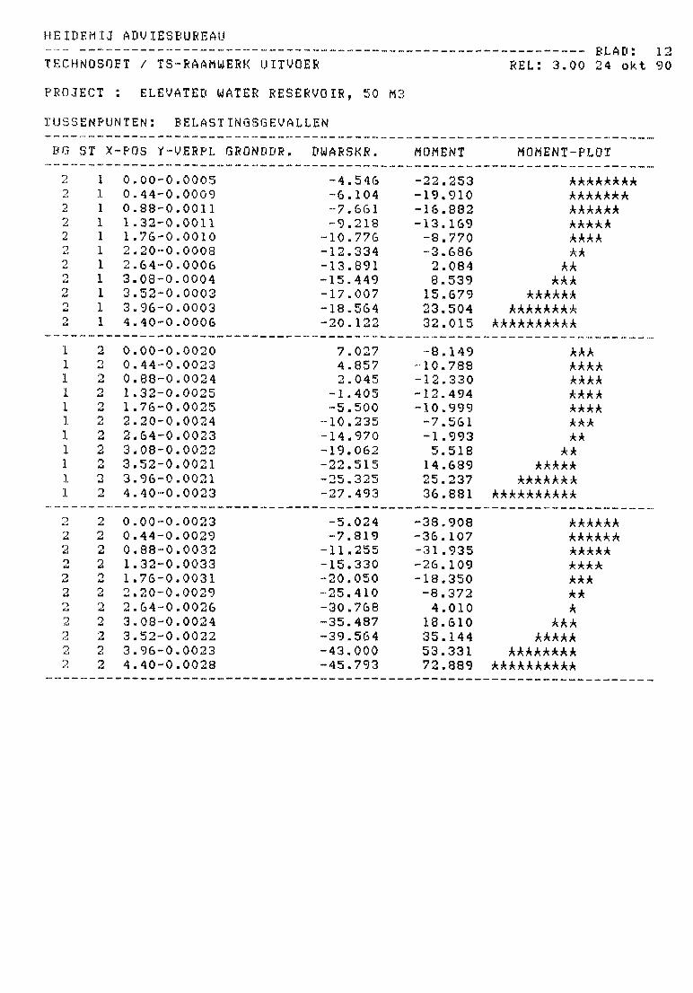
IE IDEM I J ADVIESBUREAU
TECHNOSQET / TS-RAAMWERK UITVQER
PROJECT : ELEVATED WATER RESERVOIR, 50 M3
TUSSENPUNTEN: BELASTINGSGEVALLEN
REL: 3.00 24 okt 90
BQ ST X-POS Y-VERPL GRONDDR, DWARSKR. MOMENT MOMENT-PLOT
'22'j
222
11111111111
0.00-0.44-0.88-1.32-1.76-2.20-2.&4~3.08-3.52-3.96-4.40-
0.00050.00090.00110.00110.00100.00080.000&0.00040.00030.00030.0Q06
- 4 . 5 4 6- 6 . 1 0 4- 7 . 6 6 1- 9 . 2 1 8
-10.776•12.334-13.89115.449
•17.007-18.564-20.122
22.25319.91016.88213.169-3.770-3.6862.0848.53915.67923.50432.015
A*
AAAAAAAAA
AAAAAAAA-AAAAAAAAAA
11111111111
'••
2' • >
-t
222
2
0.00-0.44-0 .88-1.32-1 .76-2 .20-2 .64-3.08-O • \J nut
3.96-4.40-
0.00200.00230.00240.00250.00250.00240.00230.00220.00210.00210.0023
7.027 -8.149 AAA4.857 -10.788 AAAA2.045 -12.330 AAAA
-1.405 -12.494 AAAA-5.500 -10.999 AAAA-10.235 -7.561 AAA-14.970 -1.993 AA-19.062 5.518 AA•22.515 14.689 AAAAA•25.325 25.237 AAAAAAA-27.493 36.881 AAAAAAAAAA
222<•>
At
011,
0.00-0.44-i 88*"
.32-,76-
2.20-2.64-3.08-3.52-3.96-4.40-
0.00230.00290.00320.00330.00310.00290.00260.00240.00220.00230.0028
-5.024 -38.908 AAAAAA-7.819 -36.107 AAAAAA-11.255 -31.935 AAAAA•15.330 -26.109 AAAA•20.050 -18.350 AAA-25.410 -8.372 AA•30.768 4.010 A-35.487 18.610 AAA•39.564 35.144 AAAAA•43.000 53.331 AAAAAAAA•45.793 72.889 AAAAAAAAAA
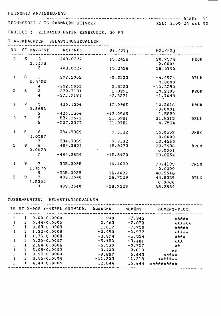
HEIDEMIJ ADVIESBUREAU
TECHNOSQFT / TS-RAAMUERK UITVOER
PROJECT : ELEVATED WATER RESERVOIR, 50 M3
STAAFKRACHTEN BELASTINGSGEVALLEN
BLAD: 11REL: 3.00 24 okt 90
BG ST KN/AFST NXi/NXj
403.0327
-403.0327
308.5002
-308.5002372.7181
-372.7181
420.1506
-420.1506527.2572
-527.2572384.9369
-384.9369484.3854
-484.3854
325.2038
-325.2038403.2540
-403.2540
DYi/DYj
15.2428
-15.2428
_ tr o O O 9%J . w u y y
5.32222.3371
-2.3371
12.0905
-12.090521.0781
-21.0781
7.3132
-7.313215.8472
-15.8472
16.4022
-16.402228.7529
-28.7529
MXi/MXj
2.01783
6 30.8450
46 3
4
7 50.8686
67 5
6
8 62.0587
78 6
2.06787
9 71.4275
89 7
1.52528
30.75740.0001
28.6896
-4.49740.0000
-16.259010.2195-1.1048
10.5016-0.00011.5889
21.8315-0. 7*534
15.05530.0000
13.466032.76860.000129.0354
23.41390.0000
40.554643.85290.0000
68.2834
DRUK
DRUK
DRUK
DRUK
DRUK
DRUK
DRUK
DRUK
DRUK
TUSSENPUNTEN: BELASTINGSGEVALLEN
BQ ST X-POS Y-VERPL GRONDDR, DUARSKR. MOMENT MOMENT-PLOT
11111111111
11
1—1
11111111
0.00-0.00040.44-0.00060.88-0.00081.32-0.00081.76-0.00082.20-0.00072.64-0.00063.08-0.00053.52-0.00043.96-0.00044.40-0.0005
1.9400.462
-1.017-2.495-3.974-5.452-6.930-8.408-9.887-11.365-12.844
-7.343-7.872-7.750-6.977-5.554-3.481-0.7572.6186.64311.31816.644 i
*****kkkkkkkkkkkkkkkkkkkkkkkkk
kkkkkkk
kkkkkkk^kkkkkkkkk
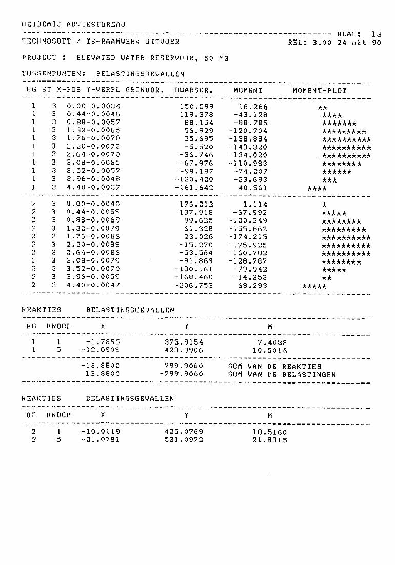
HE IDEM I J ADVIESBUREAU
TECHNOSOFT / TS-RAAMUERK UITVOER
PROJECT : ELEVATED WATER RESERVOIR, 50 M3
TUSSENPUNTEN: BELASTINGSGEVALLEN
BG ST X-POS Y-VERPL QRONDDR. DWARSKR. MOHENT
BLAD: 1 3REL: 3 . 0 0 24 o k t 90
MOMENT-PLOT
11111111111
2
EO
2*:>22
to
222
33333333333
33333333333
0.00-0.00340.44-0.00460.88-0.00571.32-0.00651.76-0.00702.20-0.00722.64-0.00703.08-0.00653.52-0.00573.96-0.00484.40-0.0037
0.00-0.00400.44-0.00550.88-0.00691.32-0.00791.76-0.00862.20-0.00882.64-0.00863.08-0.00793.52-0.00703.96-0.00594.40-0.0047
150.599119.37888.15456.92925.695-5.520-36.746-67.976-99.197130.420161.642
176.212137.91899.62561.32823.026-15.270-53.564-91.869130.161168.460206.753
16.266-43.128-38.785
-120.704-138.884-143.320-134.020-110.983-74.207-23.69340.561
1.114-67.992-120.249-155.662-174.215-175.925-160.782-128.787-79.942-14.25368.293
kk
kkkkkkkkkkkkkkkkkkkkkkkkkkkkkkkkkkkkkkkkkkkkkkkkkkkkkkkkkkkkkkk
kkkk
kkkkkkkkkkkkkkkkkkkkkkAkkkkkkkkkkkkkkkkkkkkkkkkkkkkkkkkkkkkkkkkkkkkk
kkkkk
REAKT
BG
11
REAKT
IES
KNOOP
15
IES
KNOOP
BELASTINGSGEVALLEN
X
-1.7895 375.-12.0905 423.
-13.8800 799.13.8800 -799.
BELASTINGSGEVALLEN
X
Y
91549906
90609060
Y
710
SOM VANSOM VAN
M
.4088
.5016
DEDE
M
REAKTIESBELASTINGEN
215
-10.-21.
01190781
425531
.0769
.09721821
.5160
.8315
HE IDEM IJ ADVIESBUREAU
TECHNOSOFT / TS-RAAMWERK UITVOER REL: 3.00 24 okt 90
PROJECT : ELEVATED WATER RESERVOIR, 50 M3
-31.0900 956.1741 SOM VAN DE REAKTIES3.1.0900 -956.1740 SOM VAN DE BELASTINGEN

- 73 -
XO. FIGURES
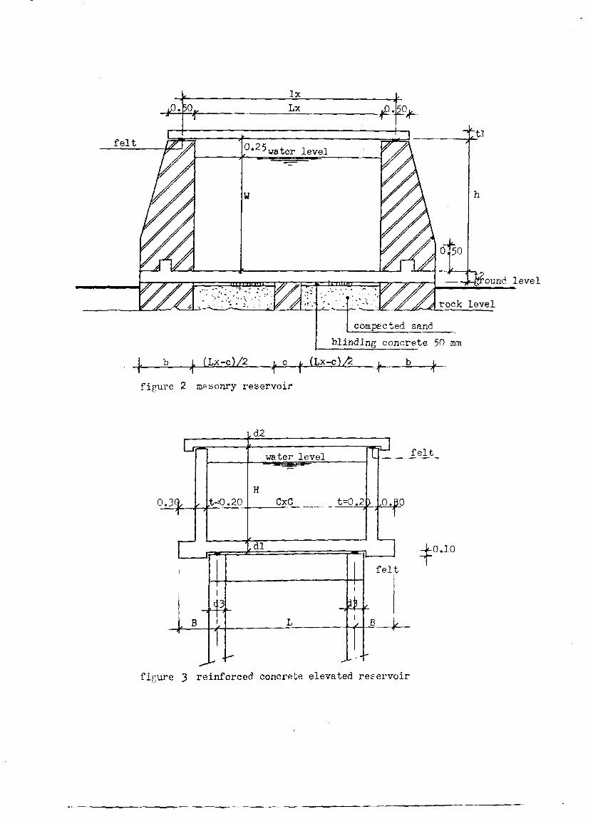
50
—--,i_ground level
rock level
compacted sand
blinding concrete 50 mm
(Lx-c)/2 (Lx-c)A
figure 2 masonry reservoir
0.3Q
I
f
J
B
,t=0.20
,d2» _ —
water level
HCxC tO. 2
f • • •
t_ —J
L
[I
. 1
fel
B
felt
BO
10
figure 3 reinforced concrete elevated reservoir
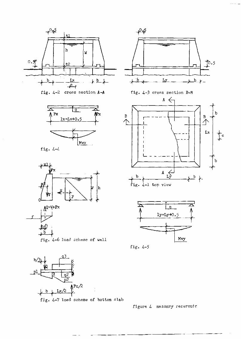
0 .
W
Lx
fig. 4.-2 cross section A-A
Pxlx=Lx+0.5
fig. 4-
fig. 4-6 load scheme of wall
L3
JS-
fig. 4.-3 cross section B-B
t'
fig.
fig. 4.-7 load scheme of bottom slab
figure 4 masonry reservoir
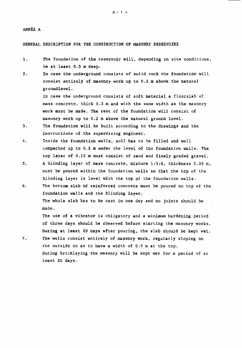
A- 1 -
ANNEX A
GENERAL DESCRIPTION FOR THE CONSTRUCTION OF MASONRY RESERVOIRS
1. The foundation of the reservoir will, depending on site conditions,
be at least 0.5 m deep.
2. In case the underground consists of solid rock the foundation will
consist entirely of masonry work up to 0.2 m above the natural
groundlevel.
In case the underground consists of soft material a floorslab of
mass concrete, thick 0.3m and with the same width as the masonry
work must be made. The rest of the foundation will consist of
masonry work up to 0.2 m above the natural ground level.
3. The foundation will be built according to the drawings and the
instructions of the supervising engineer.
4. Inside the foundation walls, soil has to be filled and well
compacted up to 0.2 m under the level of the foundation walls. The
top layer of 0.15 m must consist of sand and finely graded gravel.
5. A blinding layer of mass concrete, mixture 1:3:6, thickness 0.05 m,
must be poured within the foundation walls so that the top of the
blinding layer is level with the top of the foundation walls.
6. The bottom slab of reinforced concrete must be poured on top of the
foundation walls and the blinding layer.
The whole slab has to be cast in one day and no joints should be
made.
The use of a vibrator is obligatory and a minimum hardening period
of three days should be observed before starting the masonry works.
During at least 20 days after pouring, the slab should be kept wet.
7. The walls consist entirely of masonry work, regularly sloping on
the outside so as to have a width of 0.5 m at the top.
During bricklaying the masonry will be kept wet for a period of at
least 20 days.
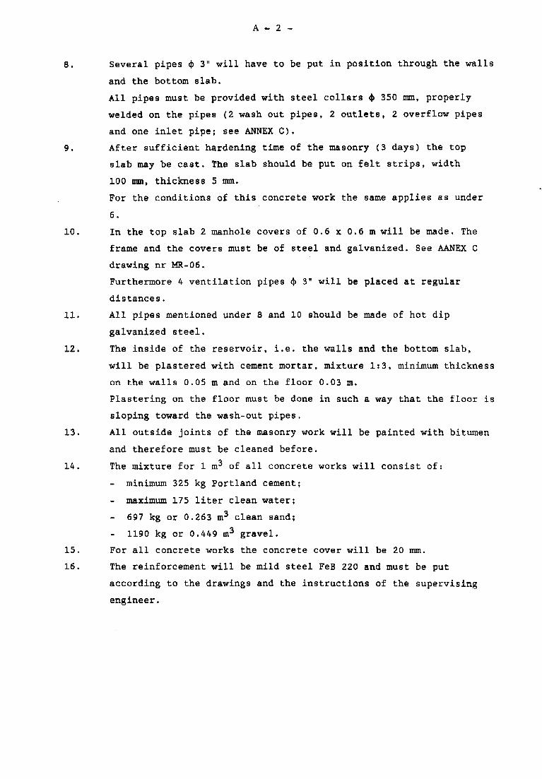
A - 2 -
8. Several pipes <J) 3" will have to be put in position through the walls
and the bottom slab.
All pipes must be provided with steel collars <|> 350 mm, properly
welded on the pipes (2 wash out pipes, 2 outlets, 2 overflow pipes
and one inlet pipe; see ANNEX C).
9. After sufficient hardening time of the masonry (3 days) the top
slab may be cast. The slab should be put on felt strips, width
100 mm, thickness 5 mm.
For the conditions o£ this concrete work the same applies as under
6.
10. In the top slab 2 manhole covers of 0.6 x 0.6 m will be made. The
frame and the covers must be of steel and galvanized. See AANEX C
drawing nr MR-06.
Furthermore 4 ventilation pipes 4> 3" will be placed at regular
distances.
11. All pipes mentioned under 8 and 10 should be made of hot dip
galvanized steel.
12. The inside of the reservoir, i.e. the walls and the bottom slab,
will be plastered with cement mortar, mixture It3, minimum thickness
on the walls 0.05 m and on the floor 0.03 m.
Plastering on the floor must be done in such a way that the floor is
sloping toward the wash-out pipes.
13. All outside joints of the masonry work will be painted with bitumen
and therefore must be cleaned before.
14. The mixture for 1 m3 of all concrete works will consist of:
- minimum 325 kg Portland cement;
- maximum 175 liter clean water;
697 kg or 0.263 m3 clean sand;
1190 kg or 0.449 m3 gravel.
15. For all concrete works the concrete cover will be 20 mm.
16. The reinforcement will be mild steel FeB 220 and must be put
according to the drawings and the instructions of the supervising
engineer.
A - 3 -
17. The strength of the concrete will be tested at a laboratory.
Therefore the contractor will make 6 cubes of the concrete mixes
required for the bottom slab and 6 cubes of the concrete mixes
required for the top slab. After 28 days of hardening these cubes
have to be tested. The minimum average cube strength should be 27
N/mm2.
The dimensions of the cubes will be 0.2 x 0.2 x 0.2 m and have to
be cast in steel moulds.
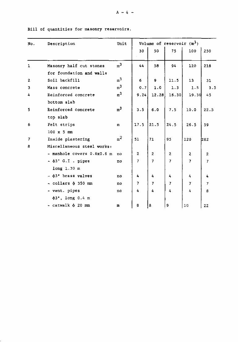
A - 4 -
Bill of quantities for masonry reservoirs,
No.
1
2
3
4
5
6
7
8
Description
Masonry half cut stones
for foundation and walls
Soil backfill
Mass concrete
Reinforced concrete
bottom slab
Reinforced concrete
top slab
Felt strips
100 x 5 mm
Inside plastering
Miscellaneous steel works:
- manhole covers 0.6x0.6 m
- cj>3" G.I . pipes
long 1.30 m
- (|)3" brass valves
- collars <}> 350 mm
- vent, pipes
<|)3H , long 0.4 m
- catwalk $ 20 mm
Unit
m3
m3
m3
m3
m3
m
m2
no
no
no
no
no
m
Volume of i
30
44
6
0.7
9.24
3.5
17.5
51
2
7
4
7
4
8
50
58
9
1.0
12.28
6.0
21.5
71
2
7
4
7
4
8
reservoir (m3)
75
94
11.5
1.3
16.30
7.5
24.5
95
2
7
4
7
4
9
100
120
13
1.5
19.30
10.0
26.5
120
2
7
4
7
4
10
250
218
31
3.5
45
22.5
59
282
2
7
4
7
8
22
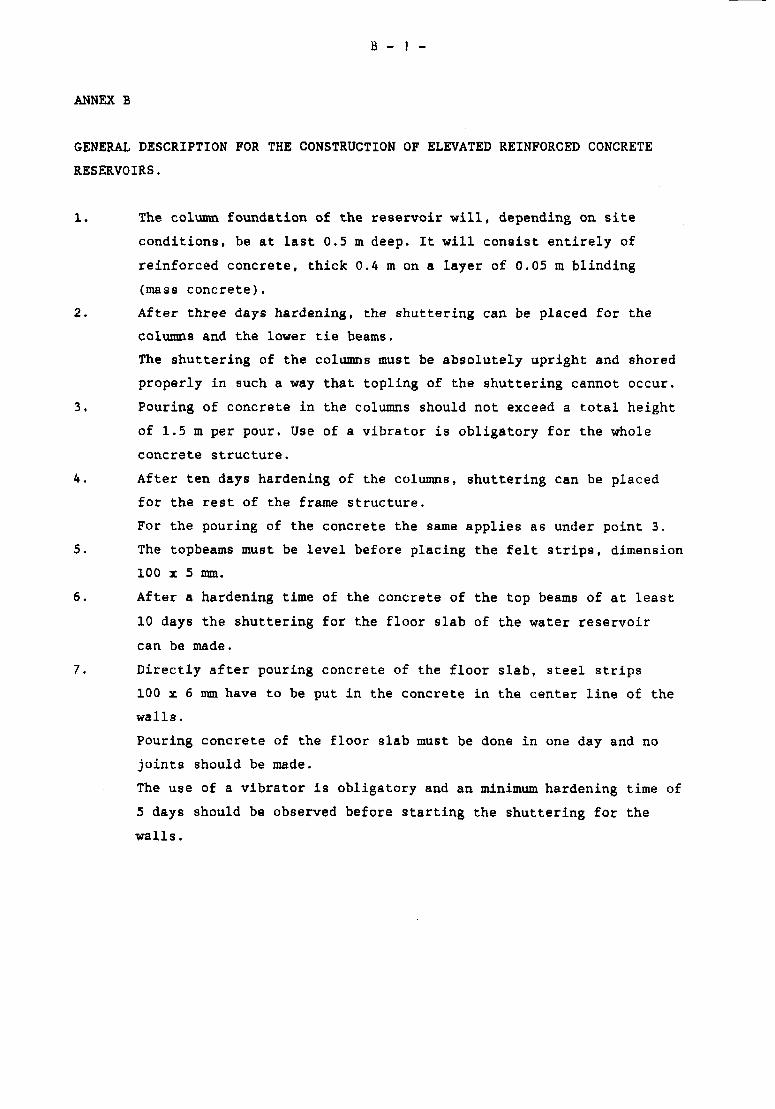
B - 1 -
ANNEX B
GENERAL DESCRIPTION FOR THE CONSTRUCTION OF ELEVATED REINFORCED CONCRETE
RESERVOIRS.
1. The column foundation of the reservoir will, depending on site
conditions, be at last 0.5 m deep. It will consist entirely of
reinforced concrete, thick 0.4 m on a layer of 0.05 m blinding
(mass concrete).
2. After three days hardening, the shuttering can be placed for the
columns and the lower tie beams.
The shuttering of the columns must be absolutely upright and shored
properly in such a way that topling of the shuttering cannot occur.
3. Pouring of concrete in the columns should not exceed a total height
of 1.5 m per pour. Use of a vibrator is obligatory for the whole
concrete structure.
A. After ten days hardening of the columns, shuttering can be placed
for the rest of the frame structure.
For the pouring of the concrete the same applies as under point 3.
5. The topbeams must be level before placing the felt strips, dimension
100 x 5 mm.
6. After a hardening time of the concrete of the top beams of at least
10 days the shuttering for the floor slab of the water reservoir
can be made.
7. Directly after pouring concrete of the floor slab, steel strips
100 x 6 mm have to be put in the concrete in the center line of the
walls.
Pouring concrete of the floor slab must be done in one day and no
joints should be made.
The use of a vibrator is obligatory and an minimum hardening time of
5 days should be observed before starting the shuttering for the
walls.
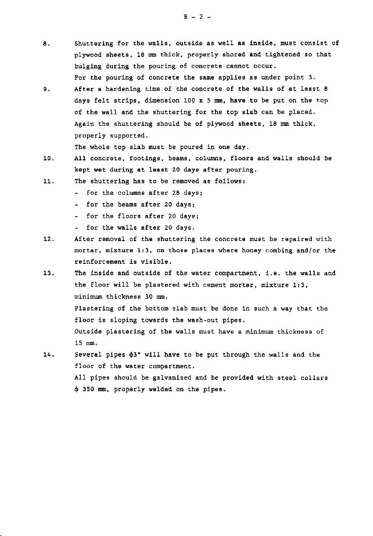
B - 2 -
8. Shuttering for the walls, outside as well as inside, must consist of
plywood sheets, 18 mm thick, properly shored and tightened so that
bulging during the pouring of concrete cannot occur.
For the pouring of concrete the same applies as under point 3.
9. After a hardening time of the concrete of the walls of at least 8
days felt strips, dimension 100 x 5 mm, have to be put on the top
of the wall and the shuttering for the top slab can be placed.
Again the shuttering should be of plywood sheets, 18 mm thick,
properly supported.
The whole top slab must be poured in one day.
10. All concrete, footings, beams, columns, floors and walls should be
kept wet during at least 20 days after pouring.
11. The shuttering has to be removed as follows:
for the columns after 28 days;
for the beams after 20 days;
for the floors after 20 days;
for the walls after 20 days.
12. After removal of the shuttering the concrete must be repaired with
mortar, mixture 1:3, on those places where honey combing and/or the
reinforcement is visible.
13. The inside and outside of the water compartment, i.e. the walls and
the floor will be plastered with cement mortar, mixture 1:3,
minimum thickness 30 mm.
Plastering of the bottom slab must be done in such a way that the
floor is sloping towards the wash-out pipes.
Outside plastering of the walls must have a minimum thickness of
15 mm.
14. Several pipes (|)3" will have to be put through the walls and the
floor of the water compartment.
All pipes should be galvanised and be provided with steel collars
c|) 350 mm, properly welded on the pipes.
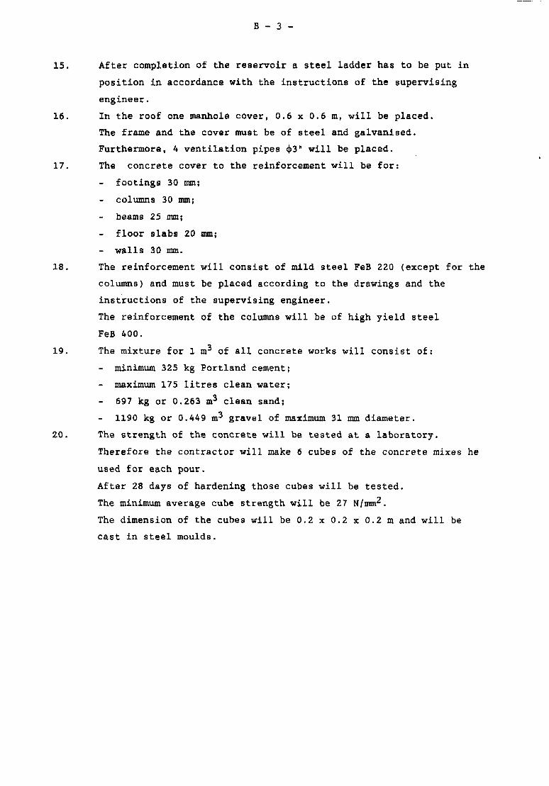
B - 3 -
15. After completion of the reservoir a steel ladder has to be put in
position in accordance with the instructions of the supervising
engineer.
16. In the roof one manhole cover, 0.6 x 0.6 m, will be placed.
The frame and the cover must be of steel and galvanised.
Furthermore, 4 ventilation pipes (j>3" will be placed.
17. The concrete cover to the reinforcement will be for:
footings 30 mm;
columns 30 mm;
beams 25 mm;
floor slabs 20 mm;
- walls 30 mm.
18. The reinforcement will consist of mild steel FeB 220 (except for the
columns) and must be placed according to the drawings and the
instructions of the supervising engineer.
The reinforcement of the columns will be of high yield steel
FeB 400.
19. The mixture for 1 m of all concrete works will consist of:
minimum 325 kg Portland cement;
maximum 175 litres clean water;
697 kg or 0.263 m^ clean sand;
1190 kg or 0.449 m^ gravel of maximum 31 mm diameter.
20. The strength of the concrete will be tested at a laboratory.
Therefore the contractor will make 6 cubes of the concrete mixes he
used for each pour.
After 28 days of hardening those cubes will be tested.
The minimum average cube strength will be 27 N/mm^.
The dimension of the cubes will be 0.2 x 0.2 x 0.2 m and will be
cast in steel moulds.
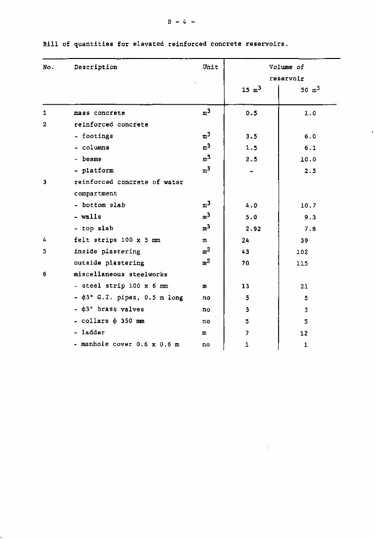
B - 4 -
Bill of quantities for elevated reinforced concrete reservoirs.
No.
1
2
3
4
5
6
Description
mass concrete
reinforced concrete
- footings
- columns
- beams
- platform
reinforced concrete of water
compartment
- bottom slab
- walls
- top slab
felt strips 100 x 5 mm
inside plastering
outside plastering
miscellaneous steelworks
- steel strip 100 x 6 mm
- (|)3" G.I. pipes, 0.5 m long
- c))3" brass valves
- collars <{> 350 mm
- ladder
- manhole cover 0.6 x 0.6 m
Unit
m3
m3
m3
m3
m3
m3
m3
m3
m
m*
m2
m
no
no
no
m
no
15 m 3
0.5
3.5
1.5
2.5
-
4.0
5.0
2.92
24
43
70
13
5
3
5
7
1
Volume of
reservoir
50 m3
1.0
6.0
6.1
10.0
2.5
10.7
9.3
7.8
39
102
115
21
5
3
5
12
1