Embed Size (px)
Citation preview

WATER RESOURCES AUTHORITY
RESTRICTED TENDER
TENDER NO: WRA/T/001/2020-2021 LOT 1 & 2
TENDER NAME:
DRILLING AND ASSOCIATED DATA COLLECTION BOREHOLE AT BANGALI
WITHIN TANA RIVER COUNTY LOT -1 AND DRILLING AND ASSOCIATED
DATA COLLECTION FOR AN EXPLORATORY BOREHOLE AT ENDEMBESS,
TRANS NZOIA COUNTY LOT -2
ISSUE DATE: 30TH
JULY, 2020
CLOSING DATE: 6TH
AUGUST, 2020 AT 11.00AM
TABLE OF CONTENTS
PAGE
INTRODUCTION …………………………………… 1
SECTION I INVITATION FOR TENDERS …………………………… 2
SECTION II INSTRUCTIONS TO TENDERERS …………………… 4
SECTION III CONDITIONS OF CONTRACT .................................... …….11
APPENDIX TO CONDITIONS OF CONTRACT ....... 21 - 22
SECTION IV SPECIFICATIONS, DRAWINGS AND
BILLS OF QUANTITIES/SCHEDULE OF RATES……... 23
SECTION V STANDARD FORMS...................................................... 25

SECTION I
LETTER OF INVITATION FOR TENDERS
Date: 30th July, 2020
Tender reference No. WRA/T/001/2020-2021 Lot 1 & 2
Tender Name: Drilling and Associated Data Collection Borehole at Bangali
within Tana River County Lot -1 and Drilling and Associated
Data Collection for an Exploratory Borehole at Endembess,
Trans Nzoia County Lot -2
1.1 The Water Resources Authority invites sealed tenders for the Drilling and
Associated Data Collection Borehole at Bangali Within Tana River
County and Drilling and Associated Data Collection for an Exploratory
Borehole at Endembess, Trans Nzoia County from the Restricted Bidders
1.2 The invited candidates may obtain further information and inspect tender
documents at NHIF Building, Wing B, 10
th Floor, Supply Chain Office
during normal working hours.
1.2 A complete set (hard copy) of tender documents may be obtained by
interested candidates upon payment of a non-refundable fees of Kshs. 1,000
in Bankers Cheque payable to WRA, alternatively the documents may be
downloaded free of charge from www.wra.go.ke/tenders or
www.tenders.go.ke. Bidders who download the tender document from the
Government Portal- www.tenders.go.ke shall be required to email their
detailed contact information to [email protected] for future
communication.
1.3 Prices quoted should be net inclusive of all taxes, must be in Kenya shillings
and shall remain valid for (150) days from the closing date of tender.
1.4 Completed bid documents in duplicate for each Lot should be submitted in
plain sealed envelopes and clearly marked per Lot
WRA/T/001/2020-2021 Lot 1 - Drilling and Associated Data Collection
Borehole at Bangali Within Tana River County
WRA/T/001/2020-2021 Lot 2 - Drilling and Associated Data Collection for an
Exploratory Borehole at Endembess, Trans Nzoia County
The original and all copies of the bid document shall be clearly marked
“ORIGINAL” and “COPY” and shall be placed into an envelope and sealed. The
envelope shall bear the submission address and tender number and be clearly
marked, “DO NOT OPEN BEFORE 6TH
AUGUST, 2020 AT 11.00AM” and
addressed to:
The Chief Executive Officer
Water Resources Authority,
NHIF Building Wing B 9th Flr,

Ragati Rd, off Ngong Rd Nairobi
P. O. Box 45250-00100
Nairobi
1.5 Water Resources Authority (WRA) reserves the right to accept or reject any
offer giving reasons thereof and does not bind itself to accept the lowest or any
tender.
Bidders who do not adhere to the submission instruction shall be declared non
responsive. Any canvassing or giving of false information will lead to automatic
disqualification.
Chief Executive Officer
Water Resources Authority
1.6 Tenders will be opened immediately thereafter in the presence of the
candidates or their representatives who choose to attend at the boardroom
10th floor wing B, NHIF building.

SECTION II INSTRUCTIONS TO TENDERERS
TABLE OF CONTENTS
CLAUSE PAGE.
1 . GENERAL --------------------------------------- ----------- 4
2. TENDER DOCUMENTS ---------------------------------- 5
3. PREPARATION OF TENDERS --------------------------- 5 - 6
4. SUBMISSION OF TENDERS ------------------------------- 6 - 7
5. TENDER OPENING AND EVALUATON ----------------- 7 - 8
6. AWARD OF CONTRACT ------------------------------------- 8 - 9

INSTRUCTIONS TO TENDERERS.
1. General
Water Resources Authority as defined in the Appendix to Conditions of
Contract invites tenders for Drilling and Associated Data Collection
Borehole at Bangali within Tana River County Lot -1 and Drilling and
Associated Data Collection for an Exploratory Borehole at Endembess,
Trans Nzoia County Lot -2
1.1 The successful Tenderer will be expected to complete the Works by the Intended
Completion Date specified in the said Appendix.
1.2 Tenderers shall include the following statutory/mandatory information and
documents with their tenders;-
a ) Registration with the Ministry of Water & Sanitation and
Irrigation as a borehole drilling contractor
b) Valid License certificate as practicing borehole drilling
contractor from the Ministry of Water & Sanitation and
Irrigation in the year 2020.
c) Certified copy of certificates of Business
registration/Incorporation
d) Certified Valid Business Trading License Permit from County
Government
e) Certified copy of Current CR12 form/ BN whichever is
applicable
f) Valid Tax compliance certificate
g) Valid Certificate of registrat ion with National
Construction Authority (NCA) in the Water Works
Category i n t h e y e a r 2 0 2 0
h) Original Tender/ Bid security of Kshs 100,000 for each lot
(Kenya Shillings One Hundred Thousand) in form of Insurance
Bond/Bank Guarantee from financial institution recognized by
PPRA valid for 30 days from the Tender submission deadline.
i) Submission o f T w o b i d d o c u m e n t s ( clearly m a r k e d
‘Original’ and ‘Copy’) in a perfect bound (No spiral binding)
and correctly serialized / paginated and initialized by binder/
rubber stamped.
j) Correctly duly filled and signed Form of Tender in WRA’s
Tender Document Template)
1.3 The T e n d e r e r s h a l l b e a r a l l c o s t s a s s o c i a t e d
w i t h the preparation and submission of his tender, and Water
Resources Authority will in no case be responsible or liable for those
costs.
1.4 The Tenderer, at the Tenderer’s own responsibility and risk, is
encouraged to visit and examine the Site of the Works and its
surroundings, and obtain all information that may be necessary for
preparing the tender and entering into a contract for construction of
the Works. The costs of visiting the Site shall be at the Tenderer’s own
expense.
1.5 The WRA employees, committee members, board members and their
relative (spouse and children) are not eligible to participate in the
tender.
1.6 The WRA shall allow the tenderer to review the tender document free
of charge before purchase.
2. Tender Documents
2.1 The complete set of tender documents comprises the
documents listed here below and any addenda issued in accordance
with clause 2.4 here below:-
a. Form of Invitation for Tender
b. Instructions to Tenderers
c. Form of Tender
d. General Conditions of Contract and Special Conditions of Contract
e. Specifications
f. Bill of Quantities
g. Drawings
h. Declaration FORM
2.2 The Tenderer shall examine all instructions, forms and specifications in
the tender documents. Failure to furnish all information required by
the tender documents may result in rejection of his tender.
2.3 A prospective Tenderer making inquiries of the tendering documents
may notify Water Resources Authority in writing or by email through
the address indicated in the letter of invitation to tender (clause 1.4).
Water Resources Authority will respond to any request for clarification
received earlier than seven [7] days prior to the deadline for
submission of tenders. Copies of Water Resources Authority’s response
will be forwarded to all persons issued with tendering
documents, including a description of the inquiry, but without
identifying its source.
2.4 Before the deadline for submission of tenders, Water Resources
Authority may modify the tendering documents by issuing addenda.
Any addendum thus issued shall be part of the tendering documents
and shall be communicated in writing or by email to all Tenderers.
Prospective Tenderers shall acknowledge receipt of each addendum in
writing to Water Resources Authority.
2.5 To give prospective Tenderers reasonable time in which to take an
addendum into account in preparing their tenders, Water Resources
Authority may extend, as necessary, the deadline for submission of
tenders in accordance with clause 4.2 here below.
3. Preparation of Tenders

3.1 All documents relating to the tender and any correspondence shall
be in English Language.
3.2 The tender submitted by the Tenderer shall comprise the following:-
(a) The Tender;
(b) Tender Security;
(c) Priced Bill of Quantities/Schedule of Rates for lump-sum
Contracts
(d) Any other materials required to be completed and
submitted by Tenderers.
3.3 The Tenderer shall fill in rates and prices for all items of the Works
described in the Bill of Quantities/Schedule of Rates. Items for which
no rate or price is entered by the Tenderer will not be paid for when
executed and shall be deemed covered by the other rates and prices in
the Bill of Quantities/Schedule of Rates. All duties, taxes and other
levies payable by the Contractor under the Contract, as of 30 days
prior to the deadline for submission of tenders, shall be included in the
tender price submitted by the Tenderer.
3.4 The rates and prices quoted by the Tenderer shall not be subject to any
adjustment during the performance of the Contract.
3.5 The unit rates and prices shall be in Kenya Shillings.
3.6 Tenders shall remain valid for a period of one hundred and
twenty (150) days from the date of submission. However, in
exceptional circumstances, Water Resources Authority may request
that the Tenderers extend the period of validity for a specified
additional period. The request and the Tenderers’ responses shall be
made in writing.
3.7 The Tenderer shall prepare one original of the documents comprising
the tender documents as described in these Instructions
to Tenderers.
3.8 The original shall be typed or written in indelible ink and shall be
signed by a person or persons duly authorized to sign on behalf of the
Tenderer. All pages of the tender where alterations or additions have
been made shall be initialed by the person or persons signing the
tender.
3.9 Clarification of tenders shall be requested by the tenderer to be
received by the procuring entity not later than 7 days prior to the
deadline for submission of tenders.
3.10 WRA shall reply to any clarifications sought by the tenderer within
3 days of receiving the request to enable the tenderer to make timely
submission of its tender.

4. Submission of Tenders
4.1 The tender duly filled and sealed in an envelope shall; -
(a) be addressed to Water Resources Authority at the address provided in
the invitation to tender;
[b] bear the name and identification number of the Contract as defined
in the invitation to tender; and
[c] provide a warning not to open before the specified time and date for
tender opening.
4.2 Tenders shall be delivered to Water Resources Authority at the address
specified above not later than the time and date specified in the
invitation to tender.
4.3 The tenderer shall not submit any alternative offers unless they are
specifically required in the tender documents.
4.4 Tenderers may bid for one or more lots.
4.5 Any tender received after the deadline for opening tenders will be
returned to the tenderer un-opened.
4.6 Water Resources Authority may extend the deadline for submission
of tenders by issuing an amendment in accordance with sub-clause 2.5
in which case all rights and obligations of Water Resources Authority
and the Tenderers previously subject to the original deadline will then
be subject to the new deadline.
5. Tender Opening and Evaluation
5.1 The tenders will be opened in the presence of the Tenderers’
representatives who choose to attend at the time and in the place
specified in the invitation to tender.
5.2 The Tenderers’ names, the total amount of each tender, the
presence of requisite tender surety and such other details as may be
considered appropriate, will be announced at the opening by Water
Resources Authority. Minutes of the tender opening, including the
information disclosed to those present will also be prepared by Water
Resources Authority.
5.3 Information relating to the examination, clarification,
evaluation and comparison of tenders and recommendations for the
award of the Contract shall not be disclosed to Tenderers or any other
persons not officially concerned with such process until the
award to the successful Tenderer has been announced. Any
effort by a Tenderer to influence Water Resources Authority’s officials,
processing of tenders or award decisions may result in the rejection of

his tender.
5.4 The tender sum as submitted and read out during the tender opening
shall be absolute and final and shall not be the subject of correction.
5.5 The tender evaluation committee shall evaluate the tender within 30
days of the validity period from the date of opening the tender.
5.6 Contract price variations shall not be allowed for contracts not
exceeding one year (12 months)
5.7 Where Contract Price variation is allowed, the cumulative value (price
and quantity) shall not exceed 25% of the original Contract Price.
5.8 Price variation requests shall be processed by the procuring entity
within 30 days of receiving the request.
5...9 Preference where allowed in the evaluation of tenders shall not exceed
15%
5.10 To assist in the examination, evaluation, and comparison of tenders,
Water Resources Authority at his discretion, may request [in writing]
any Tenderer for clarification of the tender, including breakdowns of
unit rates. The request for clarification and the response shall be in
writing or email but no change in the tender price or substance of the
tender shall be sought, offered or permitted.
5.11 The Tenderer shall not influence Water Resources Authority on any
matter relating to his tender from the time of the tender opening to the
time the Contract is awarded. Any effort by the Tenderer to
influence Water Resources Authority or his employees in his
decision on tender evaluation, tender comparison or Contract award
may result in the rejection of the tender.
6. Award of Contract
6.1 The award of the Contract will be made to the Tenderer who has
offered the lowest evaluated tender price as outlined in the evaluation
criteria.
6.2 Notwithstanding the provisions of clause 6.1 above, Water Resources
Authority reserves the right to accept or reject any tender and to cancel
the tendering process and reject all tenders at any time prior to the
award of Contract without thereby incurring any liability to the
affected Tenderer or Tenderers or any obligation to inform the
affected Tenderer or Tenderers of the grounds for the action.
6.3 The Tenderer whose tender has been accepted will be notified of the
award prior to expiration of the tender validity period in writing or
email. This notification (hereinafter and in all Contract documents
called the “Letter of Acceptance”) will state the sum [hereinafter and in

all Contract documents called the “Contract Price” which Water
Resources Authority will pay the Contractor in consideration of the
execution, completion, and maintenance of the Works by the
Contractor as prescribed by the Contract. The contract shall be formed
on the parties signing the contract. At the same time the other tenderers
shall be informed that their tenders have not been successful.
6.4 Within fourteen (14) days of receipt of the Form of contract
agreement/notification for contract award from Water Resources
Authority, the successful tenderer shall sign the form and return it to
Water Resources Authority together with the required Performance
Security as stipulated in the Special Conditions of Contract.
6.5 The Contract Agreement will incorporate all agreements between Water
Resources Authority and the successful Tenderer and they shall have it
signed by the parties within 30 days from the date of notification of
contract award unless there is an administrative review request.
6.6 The Water Resources Author i ty may at any time terminate
procurement proceedings before contract award and shall not be liable
to any person for the termination.

6.7 The procuring entity shall give prompt notice of the termination to the
tenderers and on request give its reasons for termination within 14
days of receiving the request from any tenderer.
7. Corrupt and fraudulent practices
7.1 The procuring entity requires that the tenderer observes the highest
standard of ethics during the procurement process and execution of the
contract. A tenderer shall sign a declaration that he has not and will
not be involved in corrupt and fraudulent practices.
7.2 The procuring entity will reject a tender if it determines that the
tenderer recommended for award has engaged in corrupt and
fraudulent practices in competing for the contract in question.
7.3 Further a tenderer who is found to have indulged in corrupt and
fraudulent practices risks being debarred from participating in public
procurement in Kenya.

SECTION III CONDITIONS OF CONTRACT
Table of Clauses Page
1. DEFINITIONS………………………………………………………… 11
2. CONTRACT DOCUMENTS…………………………………………
12
3. EMPLOYER’S REPRESENTATIVE’S DECISIONS…………….
13
4. WORKS, LANGUAGE AND LAW OF CONTRACT………………
13
5. SAFETY, TEMPORARY WORKS AND DISCOVERIES…………
13
6. WORK PROGRAM AND SUB-CONTRACTING…………………..
13
7. THE SITE………………………………………………………….
13 – 14
8. INSTRUCTIONS………………………………………………………
14
9. EXTENSION OF COMPLETION DATE……………………………
14 – 15
10. MANAGEMENT MEETINGS…………………………………………
15
11. DEFECTS………………………………………………………………
15 – 16
12. BILLS OF QUANTITIES/SCHEDULE OF RATES………………
16
13. VARIATIONS……………………………………………………………
16
14. PAYMENT CERTIFICATES AND FINAL ACCOUNT ……………
16 – 17
15. INSURANCES …………………………………………………………
18
16. LIQUIDATED DAMAGES……………………………………………
18
17. COMPLETION AND TAKING OVER………………………………
18
18. TERMINATION…………………………………………………………
18 – 19
19. PAYMENT UPON TERMINATION…………………………………
19
20. CORRUPT GIFTS AND PAYMENTS OF COMMISSION………
19 – 20
21. SETTLEMENT OF DISPUTES………………………………………
20
22. APPENDIX TO CONDITIONS OF CONTRACT …………………
21 – 22

SECTION III - CONDITIONS OF CONTRACT:-GENERAL CONDITIONS
1. Definitions
1.1 In this Contract, except where context otherwise requires, the
following terms shall be interpreted as indicated;
“Bills of Quantities” means the priced and completed Bill of
Quantities forming part of the tender [where applicable].
“Schedule of Rates” means the priced Schedule of Rates forming part
of the tender [where applicable].
“The Completion Date” means the date of completion of the Works
as certified by Water Resources Authority’s Representative.
“The Contract” means the agreement entered into by Water Resources
Authority and the Contractor as recorded in the Agreement Form and
signed by the parties.
“The Contractor” refers to the person or corporate body whose tender
to carry out the Works has been accepted by Water Resources
Authority.
“The Contractor’s Tender” is the completed tendering document
submitted by the Contractor to Water Resources Authority.
“The Contract Price” is the price stated in the Letter of
Acceptance.
“Days” are calendar days; “Months” are calendar months.
“A Defect” is any part of the Works not completed in accordance with
the Contract.
“The Defects Liability Certificate” is the certificate issued by WRA
Representative upon correction of defects by the Contractor.
“The Defects Liability Period” is the period named in the Appendix to
Conditions of Contract and calculated from the Completion Date.
“Drawings” include calculations and other information provided or
approved by Water Resources Authority’s Representative for the
execution of the Contract.

“Employer” Includes Central or Local Government administration,
Universities, Public Institutions and Corporations and is the party who
employs the Contractor to carry out the Works.
“Equipment” is the Contractor’s ma ch i ne r y and v eh i c l e s
brought temporarily to the Site for the execution of the Works.
“Site” means the place or places where the permanent Works are to be
carried out including workshops where the same is being prepared.
“Materials” are all supplies, including consumables, used by the
Contractor for incorporation in the Works.
“Employer’s Representative” is the person appointed by Water
Resources Authority and notified to the Contractor for the purpose of
supervision of the Works.
“Specification” means the Specification of the Works included in the
Contract.
“Start Date” is the date when the Contractor shall commence
execution of the Works.
“A Subcontractor” is a person or corporate body who has a Contract
with the Contractor to carry out a part of the Work in the Contract,
which includes Work on the Site.
“Temporary works” are works designed, constructed, installed, and
removed by the Contractor which are needed for construction or
installation of the Works.
“ A Variation” is an instruction given by Water Resources
Authority’s Representative which varies the Works.
“The Works” are what the Contract requires the Contractor to
construct, install, and turnover to Water Resources Authority.
2. Contract Documents
2.1 The following documents shall constitute the Contract
documents and shall be interpreted in the following order of priority;
(1) Agreement,
(2) Letter of Acceptance,
(3) Contractor’s Tender,
(4) Conditions of Contract,
(5) Specifications,
(6) Drawings,
(7) Bills of Quantities or Schedule of Rates
3. Employer’s Representative’s Decisions
3.1 Except where otherwise specifically stated, Water Resources
Authority’s Representative will decide contractual matters between
Water Resources Authority and the Contractor in the role representing
Water Resources Authority.
4. Works, Language and Law of Contract
4.1 The Contractor shall construct and install the Works in accordance
with the Contract documents. The Works may commence on the Start
Date and shall be carried out in accordance with the Program
submitted by the Contractor, as updated with the approval of Water
Resources Authority’s Representative, and complete them by the
Intended Completion Date.
4.2 The ruling language of the Contract shall be English language and the
law governing the Contract shall be the law of the Republic of Kenya.
5. Safety, Temporary works and Discoveries
5.1 The Contractor shall be responsible for design of temporary works
and shall obtain approval of third parties to the design of the
temporary works where required.
5.2 The Contractor shall be responsible for the safety of all activities on the
Site.
5.3 Anything of historical or other interest or significant value
unexpectedly discovered on the Site shall be the property of Water
Resources Authority. The Contractor shall notify Water Resources
Authority’s Representative of such discoveries and carry out
Water Resources Authority’s Representative’s instructions for
dealing with them.
6. Work Program and Sub-contracting
6.1 Within seven days after Site possession date, the Contractor shall
submit to Water Resources Authority’s Representative for approval a
program showing the general methods, arrangements, order
and timing for all the activities in the Works.

6.2 The Contractor may sub-contract the Works (but only to a
maximum of 25 percent of the Contract Price) with the approval of
Water Resources Authority’s Representative. However, he shall not
assign the Contract without the approval of Water Resources
Authority in writing. Sub-contracting shall not alter the Contractor’s
obligations.
7. The site
7.1 Water Resources Authority shall give possession of all parts of the Site
to the Contractor.
7.2 The Contractor shall allow Water Resources Authority’s
Representative and any other person authorized by Water Resources
Authority’s Representative, access to the Site and to any place where
work in connection with the Contract is being carried out or is
intended to be carried out.
8. Instructions
8.1 The Contractor shall carry out all instructions of Water Resources
Authority’s Representative which are in accordance with the Contract.
9 Extension of Completion Date
9.1 Water Resources Authority shall extend the Completion Date if an
occurrence arises which makes it impossible for completion to be
achieved by the Intended Completion Date. Water Resources
Authority shall decide whether and by how m u c h to extend the
Completion Date.
9.2 For the purposes of this clause, the following occurrences shall be valid
for consideration;
Delay by:-
(a) force majeure, or
(b) reason of any exceptionally adverse weather conditions, or
(c) reason of civil commotion, strike or lockout affecting any of the
trades employed upon the Works or any of the trades engaged
in the preparation, manufacture or transportation of any of the
goods or materials required for the Works, or

(d) reason of Water Resources Authority’s Representative’s
instructions issued under these Conditions, or
(e) reason of the contractor not having received in due time
necessary instructions, drawings, details or levels from Water
Resources Authority’s Representative for which he specifically
applied in writing on a date which having regard to the date
for Completion stated in the appendix to these Conditions or to
any extension of time then fixed under this clause was neither
unreasonably distant from nor unreasonably close to the date
on which it was necessary for him to receive the same, or
(f) delay on the part of artists, tradesmen or others engaged by
Water Resources Authority in executing work not forming part
of this Contract, or
(g) reason of delay by statutory or other services providers or
similar bodies engaged directly by Water Resources Authority,
or
(h) reason of opening up for inspection of any Work covered up
or of the testing or any of the Work, materials or goods in
accordance with these conditions unless the inspection or test
showed that the Work, materials or goods were not in
accordance with this Contract, or
(i) reason of delay in appointing a replacement Employer’s
Representative, or
(j) reason of delay caused by the late supply of goods or
materials or in executing Work for which Water Resources
Authority or his agents are contractually obliged to supply or to
execute as the case may be, or
(k) delay in receiving possession of or access to the Site.
10 Management Meetings
10.1 A Contract management meeting shall be held regularly and
attended by Water Resources Authority’s Representative and the
Contractor. Its business shall be to review the plans for the remaining
Work. Water Resources Authority’s Representative shall record the
business of management meetings and provide copies of the record to
those attending the meeting and Water Resources Authority. The
responsibility of the parties for actions to be taken shall be decided by
Water Resources Authority’s Representative either at the management

meeting or after the management meeting and stated in writing to all
who attend the meeting.
10.2 Communication between parties shall be effective only when in
writing.
11 Defects
11.1 Water Resources Authority’s Representative shall inspect the
Contractor’s work and notify the Contractor of any defects that are
found. Such inspection shall not affect the Contractor’s responsibilities.
Water Resources Authority’s Representative may instruct the
Contractor to search for a defect and to uncover and test any Work
that Water Resources Authority’s Representative considers may have a
defect. Should the defect be found, the cost of uncovering and making
good shall be borne by the Contractor. However, if there is no defect
found, the cost of uncovering and making good shall be treated as a
variation and added to the Contract Price.
11.2 Water Resources Authority’s Representative shall give notice to the
Contractor of any defects before the end of the Defects Liability
Period, which begins at Completion, and is defined in the Appendix to
Conditions of Contract.
11.3 Every time notice of a defect is given, the Contractor shall
correct the notified defect within the length of time specified by Water
Resources Authority’s Representative’s notice. If the Contractor has not
corrected a defect within the time specified in Water Resources
Authority’s Representative’s notice, Water Resources Authority’s
Representative will assess the cost of having the defect corrected by
other parties and such cost shall be treated as a variation and be
deducted from the Contract Price.
12 Bills of Quantities/Schedule of Rates
12.1 The Bills of Quantities/Schedule of Rates shall contain items for the
construction, installation, testing and commissioning of the Work to be
done by the Contractor. The Contractor will be paid for the quantity
of the Work done at the rates in the Bills of Quantities/Schedule of
Rates for each item. Items against which no rate is entered by the
Tenderer will not be paid for when executed and shall be deemed
covered by the rates for other items in the Bills of Quantities/Schedule
of Rates.
12.2 Where Bills of Quantities do not form part of the Contract, the
Contract Price shall be a lump sum (which shall be deemed to have
been based on the rates in the Schedule of Rates forming

part of the tender) and shall be subject to re-measurement after each
stage.
13 Variations
13.1 The Contractor shall provide Water Resources Authority’s
Representative with a quotation for carrying out the variations when
requested to do so. Water Resources Authority’s Representative
shall assess the quotation and shall obtain the necessary authority from
Water Resources Authority before the variation is ordered.
13.2 If the Work in the variation corresponds with an item description in
the Bill of Quantities/Schedule of Rates, the rate in the Bill of
Quantities/Schedule of Rates shall be used to calculate the value of the
variation. If the nature of the Work in the variation does not
correspond with items in the Bill of Quantities/Schedule of Rates, the
quotation by the Contractor shall be in the form of new rates for the
relevant items of Work.
13.3 If the Contractor’s quotation is unreasonable, Water Resources
Authority’s Representative may order the variation and make a change
to the Contract Price, which shall be based on Water Resources
Authority’s Representative’s own forecast of the effects of the
variation on the Contractor’s costs.
14 Payment Certificates and Final Account
14.1 The Contractor shall be paid after each of the following stages of
Work listed here below (subject to re-measurement by Water
Resources Authority’s Representative of the Work done in each stage
before payment
is made). In case of lump-sum Contracts, the valuation for each stage
shall be based on the quantities so obtained in the re- measurement
and the rates in the Schedule of Rates.
20% of the contract price shall be paid upon completion mobilization
of community members, machinery and procurement of drilling
equipment and tools and having a proof of having started drilling
works.
30% of contract price upon submission of borehole drilling completion draft
report.
20% of contract price upon submission of borehole drilling completion
final report.
10% of contract price, defects liability to be paid after 90 days

14.2 Upon deciding that Works included in a particular stage are
complete, the Contractor shall submit to Water Resources Authority’s
Representative his application for payment. Water Resources
Authority’s Representative shall check, adjust if necessary and certify
the amount to be paid to the Contractor within 21 days of receipt of
the Contractor’s application. Water Resources Authority shall pay the
Contractor the amounts so certified within 30 days of the date of issue
of each Interim Certificate.
14.3 The Contractor shall supply Water Resources Authority’s
Representative with a detailed final account of the total amount that
the Contractor considers payable under the Contract before the end of
the Defects Liability Period. Water Resources Authority’s
Representative shall issue a Defect Liability Certificate and certify
any final payment that is due to the Contractor within 30 days of
receiving the Contractor’s account if it is correct and complete. If it is
not, Water Resources Authority’s Representative shall issue within 21
days a schedule that states the scope of the corrections or additions
that are necessary. If the final account is still unsatisfactory after it has
been resubmitted, Water Resources Authority’s Representative shall
decide on the amount payable to the Contractor and issue a Final
Payment Certificate. Water Resources Authority shall pay the
Contractor the amount so certified within 60 days of the issue of the
Final Payment Certificate.
14.4 If the period laid down for payment to the Contractor upon each of
Water Resources Authority’s Representative’s Certificate by Water
Resources Authority has been exceeded, the Contractor shall be
entitled to claim simple interest calculated pro-rata on the basis of the
number of days delayed at the
Central Bank of Kenya’s average base lending rate prevailing on the first
day the payment becomes overdue. The Contractor will be required to
notify Water Resources Authority within 15 days of receipt of delayed
payments of his intentions to claim interest.
15. Insurance
15.1 The Contractor shall be responsible for and shall take out
appropriate cover against, among other risks, personal injury; loss of
or damage to the Works, materials and plant; and loss of or damage
to property.
16. Liquidated Damages
16.1 The Contractor shall pay liquidated damages to Water Resources
Authority at the rate 0.001 per cent of the Contract price per day for
each day that the actual Completion Date is later than the Intended
Completion Date except in the case of any of the occurrences listed
under clause 9.2. Water Resources Authority may deduct liquidated
damages from payments due to the Contractor. Payment of liquidated

damages shall not affect the Contractor’s liabilities.
17. Completion and Taking Over
17.1 Upon deciding that the Work is complete the Contractor shall
request Water Resources Authority’s Representative to issue a
Certificate of Completion of the Works, upon deciding that the Work
is completed.
Water Resources Authority shall take over the Site and the Works
within seven days of Water Resources Authority’s Representative
issuing a Certificate of Completion.
18. Termination
18.1 Water Resources Authority or the Contractor may terminate the
Contract if the other party causes a fundamental breach of the
Contract. These fundamental breaches of Contract shall include, but
shall not be limited to, the following;
(a) the Contractor stops Work for 30 days continuously without
reasonable cause or authority from W ater Resources Authority’s
Representative;
(b) the Contractor is declared bankrupt or goes into liquidation
other than for a reconstruction or amalgamation;
(c) a payment certified by Water Resources Authority’s
Representative is not paid by Water Resources Authority to the
Contractor within 30 days after the expiry of the payment
periods stated in sub clauses 14.2 and 14.3 hereinabove.
(d) Water Resources Authority’s Representative gives notice that
failure to correct a particular defect is a fundamental breach of
Contract and the Contractor fails to correct it within a
reasonable period of time.
18.2 If the Contract is terminated, the Contractor shall stop Work
immediately, and leave the Site as soon as reasonably possible. Water
Resources Authority’s Representative shall immediately thereafter
arrange for a meeting for the purpose of taking record of the Works
executed and materials, goods, equipment and temporary buildings on
Site.
19. Payment Upon Termination
19.1 Water Resources Authority may employ and pay other persons to
carry out and complete the Works and to rectify any defects and may
enter upon the Works and use all materials on Site, plant, equipment
and temporary works.

19.2 The Contractor shall, during the execution or after the
completion of the Works under this clause, remove from the Site as and
when required within such reasonable time as Water Resources
Authority’s Representative may in writing specify, any temporary
buildings, plant, machinery, appliances, goods or materials belonging
to him, and in default thereof , Water Resources Authority may
(without being responsible for any loss or damage) remove and sell
any such property of the Contractor, holding the proceeds less all costs
incurred to the credit of the Contractor.
19.3 Until after completion of the Works under this clause, Water
Resources Authority shall not be bound by any other provision of this
Contract to make any payment to the Contractor, but upon such completion
as aforesaid and the verification within a reasonable time of the accounts
therefor Water Resources Authority’s Representative shall certify the amount
of expenses properly incurred by Water Resources Authority and, if such
amount added to the money paid to the Contractor before such
determination exceeds the total amount which would have been payable on
due completion in accordance with this Contract, the difference shall be a
debt payable to Water Resources Authority by the Contractor; and if the said
amount added to the said money be less than the said total amount, the
difference shall be a debt payable by Water Resources Authority to the
Contractor.
20. Corrupt Gifts and Payments of Commission
20.1 The Contractor shall not;
(a) Offer or give or agree to give to any person in the service of
Water Resources Authority any gifts or consideration of any
kind as an inducement or reward for doing or forbearing to do
or for having done or forborne to do any act in relation to the
obtaining or execution of this or any other contract with Water
Resources Authority or for showing or forbearing to show
favour or disfavour to any person in relation to this or any other
contract with Water Resources Authority.
(b) Any breach of this Condition by the Contractor or by
anyone employed by him or acting on his behalf (whether with
or without the knowledge of the Contractor) shall be an offence
under the Laws of Kenya.
21. Settlement of Disputes
21.1 Any dispute arising out of the Contract which cannot be
amicably settled between the parties shall be referred by either
party to the arbitration and final decision of a person to be
agreed between the parties. Failing agreement to concur in
the appointment of an Arbitrator, the Arbitrator shall be
appointed by the chairman of the Chartered Institute of
Arbitrators, Kenya branch, on the request of the applying party.

SPECIAL CONDITIONS OF CONTRACT
Instruction to
tender
reference
Particulars of Appendix to instructions to tenderers
2.1
A
The Water Resources Authority invites sealed tenders for WRA/T/008/2020-
2021 Lot 1& 2
Drilling and Associated Data Collection Borehole at Bangali Within Tana
River County Lot -1
and
Drilling and Associated Data Collection for an Exploratory Borehole at
Endembess, Trans Nzoia County Lot -2
2.2
Bidders who download the tender document from the Government
Portal-www.tenders.go.ke shall be required to email their detailed contact
information to
[email protected] or future communication.
2.12.1
Particulars of tender security if applicable.
Kshs. 100,000 per Lot valid for 30 days from the Tender submission deadline
2.12.4 Form of Tender Security. The Tender Security shall be in the form of Bank
Guarantee from a reputable bank or a Guarantee from an Insurance Company
approved by the Public Procurement Regulatory Authority (PPRA).
2.13 Validity of Tenders: Tenders shall remain valid for 150 days after date of Tender
Opening
2.16.1 Deadline for submission of Tenders: 6th
August, 2020 at 11.00am
2.16.3 Bulky tenders that will not fit in the tender box shall be delivered to the
Procurement d e p a r t m e n t and will be signed for, the officer receiving
indicating date and time delivered.
2.18.1 Opening of Tenders: 6th
August, 2020 at 11.00am
11.0 The Defects Liability Period is 90 days.
The amount of performance security is 10% to be accepted in a form
of bank guarantee, in its original form
14.1 1. 20% of the contract price shall be paid upon completion
mobilization of community members, machinery and
procurement of drilling equipment and tools and having a
proof of having started drilling works.
2. 30% of contract price upon submission of borehole drilling completion draft
report.
3. 20% of contract price upon submission of borehole drilling completion final
report.
4. 10% of contract price, defects liability to be paid after 90 days

TECHNICAL SPECIFICATIONS AND FORM BILLS OF QUANTITIES FOR
PROPOSED ONE(1 NO.) EXPLORATORY BOREHOLE AT
BANGALI AREA, BURA SUB COUNTY TANA RIVER
COUNTY LOT 1
TECHNICAL SPECIFICATIONS FOR ONE (1) EXPLORATORY-CUM-
PRODUCTION BOREHOLES TO BE DRILLED WITHIN TANA RIVER
COUNTY

Table of Contents
GENERAL ......................................................................................................................................... 31
1 Introduction ........................................................................................................................ 31
2 Objective of works ............................................................................................................ 31
3 Supervision of works ......................................................................................................... 31
4 Description of the Contractor/ works ........................................................................... 31
Borehole construction ........................................................................................................... 31
Borehole pumping test ........................................................................................................... 32
5 Programme of works ........................................................................................................ 32
6 Location of the works ....................................................................................................... 32
7 Bills of quantity .................................................................................................................. 33
8 Site access and permits ...................................................................................................... 33
9 Provision of equipment, materials and labour .............................................................. 33
10 Personnel on site ................................................................................................................. 34
11 Diligent performance ......................................................................................................... 34
12 Lost bore .............................................................................................................................. 35
13 Mobilisation, demobilisation and site restitution – drilling plant .............................. 35
Description .............................................................................................................................. 35
Rates ......................................................................................................................................... 35
Drilling ..................................................................................................................................... 36
A) drilling with air/foam ....................................................................................................... 36
Rates ......................................................................................................................................... 36
14 Supply and installation of temporary / surface casing ................................................. 37
Description .............................................................................................................................. 37
Rates ......................................................................................................................................... 37
Description .............................................................................................................................. 37
Rates ......................................................................................................................................... 38
15 Geophysical Logging.......................................................................................................... 38
22 Abandonment if dry ...................................................................................................... 39
Description .............................................................................................................................. 39
Rates ......................................................................................................................................... 39
23 Supply and installation of permanent casing and screen ......................................... 39
Casing and screen specification ............................................................................................ 39
Casing and screen installation .............................................................................................. 39

Rates ......................................................................................................................................... 40
24 Supply and installation of gravel pack ........................................................................ 40
Gravel pack specification ....................................................................................................... 40
Gravel pack installation ........................................................................................................ 40
Rates ......................................................................................................................................... 41
25 Installation of backfill .................................................................................................... 41
Description .............................................................................................................................. 41
Rates ......................................................................................................................................... 41
26 Grout ................................................................................................................................ 41
Description .............................................................................................................................. 41
Grout specification and installation .................................................................................... 41
Rates ......................................................................................................................................... 41
27 Development .................................................................................................................. 42
Physical development ........................................................................................................... 42
Chemical development ......................................................................................................... 42
Rates ......................................................................................................................................... 43
28 Borehole Testing............................................................................................................. 43
Introduction ............................................................................................................................ 43
Installation, plant and methodology .................................................................................. 43
a. Pumping plant ....................................................................................................... 43
b. Pre-test .................................................................................................................... 45
c. Step-drawdown test.............................................................................................. 45
d. Constant discharge test ......................................................................................... 45
e. Recovery test and removal of plant .................................................................. 45
Rates ......................................................................................................................................... 45
29 Water sampling and analysis ........................................................................................ 46
Analysis specification ............................................................................................................. 46
Rates ......................................................................................................................................... 47
30 Borehole headworks ...................................................................................................... 47
Headworks specification ....................................................................................................... 47
Rates ......................................................................................................................................... 47
31 Borehole cap ....................................................................................................................... 47
Borehole cap specification .................................................................................................... 47
Rates ......................................................................................................................................... 48

32 Records and reporting ................................................................................................... 48
Description .............................................................................................................................. 48
Rates ......................................................................................................................................... 48
Borehole Camera Video Log................................................................................................ 48
GENERAL ........................................................................................................................................... 4
1 Introduction .......................................................................................................................... 4
2 Objective of works .............................................................................................................. 4
3 Supervision of works ........................................................................................................... 4
4 Description of the Contractor/ works ............................................................................. 4
Borehole construction ............................................................................................................. 5
Borehole pumping test ............................................................................................................. 5
5 Programme of works .......................................................................................................... 5
6 Location of the works ......................................................................................................... 6
7 Bills of quantity .................................................................................................................... 6
8 Site access and permits ........................................................................................................ 6
9 Provision of equipment, materials and labour ................................................................ 7
10 Personnel on site ................................................................................................................... 8
11 Diligent performance ........................................................................................................... 8
12 Lost bore ................................................................................................................................ 8
13 TECHNICAL SPECIFICATION, EXPLORATION/PRODUCTION BOREHOLES ............... 10
14 Mobilisation, demobilisation and site restitution – drilling plant .............................. 10
Description .............................................................................................................................. 10
Rates ......................................................................................................................................... 10
Drilling ..................................................................................................................................... 10
A) drilling with air/foam ....................................................................................................... 11
Rates ......................................................................................................................................... 11
15 Supply and installation of temporary / surface casing ................................................. 12
Description .............................................................................................................................. 12
Rates ......................................................................................................................................... 12
Description .............................................................................................................................. 12
Rates ......................................................................................................................................... 12
16 Geophysical Logging.......................................................................................................... 13
23 Abandonment if dry ...................................................................................................... 14
Description .............................................................................................................................. 14

Rates ......................................................................................................................................... 14
24 Supply and installation of permanent casing and screen ......................................... 14
Casing and screen specification ............................................................................................ 14
Casing and screen installation .............................................................................................. 14
Rates ......................................................................................................................................... 15
25 Supply and installation of gravel pack ........................................................................ 15
Gravel pack specification ....................................................................................................... 15
Gravel pack installation ........................................................................................................ 15
Rates ......................................................................................................................................... 16
26 Installation of backfill .................................................................................................... 16
Description .............................................................................................................................. 16
Rates ......................................................................................................................................... 16
27 Grout ................................................................................................................................ 16
Description .............................................................................................................................. 16
Grout specification and installation .................................................................................... 16
Rates ......................................................................................................................................... 17
28 Development .................................................................................................................. 17
Physical development ........................................................................................................... 17
Chemical development ......................................................................................................... 17
Rates ......................................................................................................................................... 18
29 Borehole Testing............................................................................................................. 18
Introduction ............................................................................................................................ 18
Installation, plant and methodology .................................................................................. 18
a. Pumping plant ....................................................................................................... 18
b. Pre-test .................................................................................................................... 20
c. Step-drawdown test.............................................................................................. 20
d. Constant discharge test ......................................................................................... 20
e. Recovery test and removal of plant .................................................................. 20
Rates ......................................................................................................................................... 21
30 Water sampling and analysis ........................................................................................ 21
Analysis specification ............................................................................................................. 21
Rates ......................................................................................................................................... 22
31 Borehole headworks .......................................................................................................... 22
Headworks specification ....................................................................................................... 22

Rates ......................................................................................................................................... 22
32 Borehole cap ................................................................................................................... 23
Borehole cap specification .................................................................................................... 23
Rates ......................................................................................................................................... 23
33 Records and reporting ................................................................................................... 23
Description .............................................................................................................................. 23
Rates ......................................................................................................................................... 23
Borehole Camera Video Log................................................................................................ 24
.

31
GENERAL
1 Introduction
This Technical Specification describes in outlines the specification for one borehole
proposed to be drilled in Bangali area in Tana River County (see table 1).
2 Objective of works
The objective of these works is to construct one (1) exploratory 203mm (8”)
boreholes with the a im of col lect ing data to enhance knowledge of
groundwater in the aqui fers in th is area. The data to be col lected
inc ludes logs of the s t rata, geophysica l log of the borehole, pumping
tes t data , water qual i ty data.
Authorizations will be provided AT the respective Water Resources Authority (WRA)
Office (Lower Tana Sub Region Office).
3 Supervision of works
The WRA shall appoint its own supervisor or inspector to monitor the conduct of
the works, who will be the client’s representative for the site. The Drilling contractor
shall have a hydrogeologist should be a licensed water resource professional with a
valid license in 2019. He/she will also demonstrate professional qualifications
degree certificate in Geology or any groundwater related degree.
WRA will inspect plant and personnel proposed by any Contractor for deployment
for the works prior to the award of contract.
4 Description of the Contractor/ works
The driller of the works should fulfill statutory registrations as a contractor of similar
works. The firm should have a valid license for the year 2019 from the Ministry of
Water &Sanitation and Irrigation and National Construction Authority and all such
condition as will be set out by the Authority towards this work.
The Contractor shall mobilise both drilling and test plant and all related equipment to
ensure their availability to undertake the works. The process shall be as follows:-
Borehole construction
1. Mobilise and Drill a borehole to a depth of 400 m at a diameter of not less
than 203 mm (8”), unless directed by the Supervising Hydrogeologist to stop
drilling at a shallower depth.
2. Collect samples at every 2 metres and lay them out as per the Code of
practice for the construction of a borehole (section 4.2)
3. Examine and record in the relevant forms the collected samples description as
per the Code of practice for the supervision of construction and test pumping
of boreholes (sections 4 and the referred forms)

32
Provided significant groundwater is encountered the following activities will
apply-:
4. Supply and install 152 mm (6”) steel casing and screen, gravel pack and inert
backfill. If a shallow saline or brackish aquifer is encountered, this may be
sealed off with grout if so instructed by the supervising hydrogeologist.
5. Develop the productive borehole.
6. Disinfect the productive borehole.
7. Carry out electrical(resistivity) and gamma logging.
8. Construct the borehole headworks as described further in this document.
9. Carry out down the hole filming using a Borehole Camera.
Borehole pumping test
1. Mobilise test pumping plant to the site and set up at the borehole to be tested
(as instructed by the Supervising hydrogeologist).
2. Install test pumping plant and conduct pumping and recovery tests in the first
borehole to be tested.
3. Sample and have the pumped water analysed for chemical and bacteriological
parameters from the borehole at the WRA Central Water Testing Laboratory.
4. Remove test pumping plant.
5. Install well cap that is tamper proof till the works are commissioned.
This outline programme are changeable: in the event that boreholes are either dry or
produce water of insufficient quantity or unacceptable salinity, it is likely that boreholes
will not be subjected to testing.
5 Programme of works
The Contractor shall provide the Supervising hydrogeologist with a detailed
Programme of Works within seven days of site handover to be drilled and the order
in which they will be drilled. This Programme shall be mutually agreed. It shall
include both a logistic and a communication plan. These shall thereafter be deemed
the Agreed Programme. The Contractor shall adhere strictly to the Agreed
Programme unless otherwise authorised by the Supervising hydrogeologist in
writing or by other mutually approved method.
This shall exclude Acts of God, Force Majeure and other unavoidable events, but
shall not exclude delays arising from mechanical plant breakdown, labour disputes
or failure to ensure that water is available on site for drilling. Acts of God explicitly
exclude normal rains. Unauthorised departure from the Agreed Programme may
incur liquidated damages.
6 Location of the works
Boreholes will be drilled in sites selected as follows in Tana River County

33
Table 1
SITE NAME LOCATION FORMATIO
N
GEOGRAPHICAL
COORDINATES
COUNTY
Bangali area Bangali Area
Sedimentary
Latitude 0.669306° South,
longitude 39.989774° East.
Tana River
Contractors should note that access to sites is on rural access roads that are in
variable condition; however, we foresee no specific problems facing mobilisation
under normal conditions with plant in normal working condition.
The Client shall make available a working area of not less than 30 x 30 m prior
to drilling plant arriving on site.
7 Bills of quantity
The Items and Rates given by the Contractor are deemed the Bills of Quantity that
shall apply to these works.
Payments will be made according to the actual depth drilled, materials installed and
works, and tests undertaken, except where errors are the responsibility of the
Contractor.
8 Site access and permits
The Client will obtain all necessary permits and authorisations. Copies of all
documentation required by the Water Resources Management Rules, 2007 will be
handed over to the Contractor as will the EIA Licence (if relevant).
9 Provision of equipment, materials and labour
The Contractor shall provide all equipment, transport, materials consumables and
labour necessary for the satisfactory completion of the Works in compliance with this
Specification. Direct rotary plant shall be deployed, capable of drilling a borehole to
a depth of 450 m at a diameter of not less than 254 mm (10”) in basalts, volcano
clastic sediments, old land surfaces and weathered and fresh Basement rock.
Bidders must be able to deploy both air (down-the-hole hammer) and fluid flush
drilling equipment for these works. The most appropriate method will be left to the
drilling contractor to decide, after consultation with the Supervising hydrogeologist.
When bidding, Contractors shall provide full specifications of all plant to be
deployed for these Works, including all downhole drilling and fishing tools
(including a Schedule of bits, stabilisers, subs, crossovers etc). The Supervising
hydrogeologist will inspect plant and materials prior to mobilisation and may reject
plant or material that in his view is sub-standard or inappropriate.
The bidder will also provide full specifications of the electrical logger and borehole

34
Camera. The electrical logger and borehole camera should be appropriate to log
or film to a maximum depth of 450m.
Bidders shall present method statements in their Proposal describing in detail the
proposed approach to these works, in which respect his attention is drawn to the need
to describe their proposed approach to the following: –
1. Logistic train available to support the works; this shall include all haulage plant
and the specification of all drilling, development, testing and associated plant; and
the Schedule of bits, stabilisers subs, crossovers etc proposed for deployment to site;
2. Proposed borehole drilling approach, including measures to overcome setbacks that
may be
encountered during drilling (including but not limited to collapse of geological
material);
3. Proposed approach to reaming (if proposed), including measures to overcome
setbacks that may be encountered during reaming (if applicable);
4. Proposed approach to the completion of the drilled borehole as a production
borehole, including specifications of casing, screen and gravel pack; proposed casing
attachment method (e.g. butt- welding or ring-welding, etc …);
5. Proposed development methodology or methodologies.
6. Confirmation of intention to comply with BS 6316 (1992) or the draft Kenya
Code of Practice for the Test Pumping of Boreholes in respect of all pumping and
recovery tests; or by providing a detailed description of the proposed approach to
conducting constant discharge and recovery tests;
10 Personnel on site
The Contractor shall provide summary details of the experience of key personnel to
be deployed for these Works, in the form of short curricula vita for each of the
principal drill team members, in particular the Hydrogeologist, Drilling Supervisor,
and three Dr i l ler s .
Elements which are considered of particular importance are years of drill team
experience in deep borehole construction in volcanic, basement and
alluvial/sedimentary formations both in the County and elsewhere in Kenya as well
as relevant professional qualifications. Demonstrated experience in the logistic
support of remote sites is also clearly advantageous.
11 Diligent performance
The Contractor shall at all times perform the Works diligently and in accordance with
sound professional practice. The Contractor shall not proceed from one stage of
works to another without the express permission of the Supervising Hydrogeologist.
Decisions regarding discontinuing any element or part of any element of these works,
or abandonment of these works, shall be discussed jointly between the Contractor
and the Supervising Hydrogeologist before any further actions are authorised by the
Supervising Hydrogeologist. The Supervising Hydrogeologist’s decision shall be final
and shall be given in writing.
The Supervising Hydrogeologist will require a written submission justifying any
steps taken or works conducted by the Contractor made without the Supervising
Hydrogeologist’s approval. An unsatisfactory explanation shall lead to non-

35
payment for works undertaken without prior agreement and may be taken into
consideration for inclusion as liquidated damages.
12 Lost bore
If the Contractor is unable to finish drilling or has to abandon a well due to the loss
of tools or any other accident or contingency that is his responsibility, the borehole
will be deemed a Lost Bore. This includes his equipment not able to drill through any
formation, it is deemed that if offered this work the plant is capable of drilling through
any formation. The Contractor shall remove all casing or drill pipe already placed in
the hole where this is possible and plug it to surface at his own expense. All material
remaining in and removed from the hole will remain the property of the Contractor.
In such a case the Client shall not pay for any of the work carried out and will
authorise in advance the drilling of a new hole at a site near the abandoned one,
after consultation with the Water Resources Authority.
In the event that a successfully-drilled borehole is deemed by the Supervising
Hydrogeologist to be dry or is of unacceptable salinity and should be abandoned,
the Contractor shall be paid for all works associated with its drilling and
abandonment and the designation Lost Bore shall not apply.
TECHNICAL SPECIFICATION, EXPLORATION/PRODUCTION BOREHOLES
Only One (1) borehole shall be constructed. The precise sites on which the boreholes
will be constructed will be shown to the Contractor by the Client or the Client’s
representative; the Contractor shall not commence setup or drilling at an unapproved
site; should he do so, all costs shall be deemed his own. All necessary permits and
authorisations will have been issued and will be made available to the Contractor
prior to mobilisation.
13 Mobilisation, demobilisation and site restitution – drilling plant
Description
The Contractor shall mobilise his drilling plant to the drill site in accordance with the
Agreed Programme. Mobilisation is deemed to include the erection, dismantling,
preparation of the drill site area and its restitution after the completion of all works;
and erection and removal of a temporary camp at the site indicated by the Client
should this be required.
On completion of works, the site shall be cleaned, and surplus material removed to
the satisfaction of the Supervising Hydrogeologist. Site re-instatement includes the
removal off-site of all hydrocarbons changed, spilled, leaked or otherwise released,
all packaging and cotton waste.
The Contractor shall make his own arrangements for the collection and transport of
water for drilling and camp purposes.
Rates
The Contractor shall provide: –

36
- A lump sum price for mobilisation and demobilisation of drilling plant, site re-
instatement, and camp, including setting up, commencing at the site.
- A lump sum price for the borehole for water provision and haulage
Drilling
Description
Boreholes shall be drilled at a diameter of not less than 203mm (8”) to allow the safe
installation of
152 mm (6”) production casing and screen, to a depth not greater than 400m.
The Contractor shall provide plant capable of drilling to a depth of 400m at a
diameter of 254mm (10”).
The Contractor shall be responsible for the drilling method or methods selected, and
neither the Client nor the Supervising Hydrogeologist shall be held responsible should
the method or methods adopted fail in the objective of drilling to a depth of at least
400 m.
With rotary methods the Contractor shall not use excessive pulldown on the bit.
Should the borehole be skewed as a result of excessive pulldown, and the borehole
not fit for purpose in consequence, the hole shall be deemed a Lost Bore. The
Contractor is required to deploy a stabiliser/drill collar of appropriate diameter when
drilling; the following table presents acceptable ranges for stabilisers/drill collars for
different borehole diameters: –
Drilling diameter, inches Recommended stabiliser diameter (range), inches
6½” 4¾” – 5”
8½” 6½” – 6¾”
9½” 6” – 7¼”
11” 8¼” – 9½”
A) drilling with air/foam
Foam used for hammer drilling and additives used for fluid rotary flush drilling must
be suited to environmental applications. The Contractor shall be responsible for
ensuring that the additives deployed are suitable for such conditions and shall furnish
the specification of all proposed additives with his proposal.
B) drilling with fluid flush
Fluid additives of bentonitic type will not be acceptable for use in these works: if fluid
rotary flush methods are to be adopted, either cellulose-based reconstituted powder
or artificial liquid anionic polymeric additives will be used for viscosity enhancement.
The Contractor will state the type and manufacturer of additive(s) to be used and will
describe the means by which the additive(s) will be mixed. The judicious application
of bentonite and cellulose or similar material will be acceptable as a means of
preventing loss of circulation in those parts of the borehole located above the aquifer
zone, though their use must be authorised in advance by the Supervising
Hydrogeologist.
Rates
The Contractor shall provide unit prices for the following: –
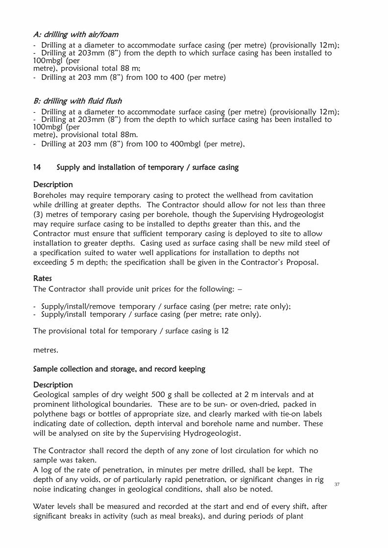
37
A: drilling with air/foam
- Drilling at a diameter to accommodate surface casing (per metre) (provisionally 12m);
- Drilling at 203mm (8”) from the depth to which surface casing has been installed to
100mbgl (per
metre), provisional total 88 m;
- Drilling at 203 mm (8”) from 100 to 400 (per metre)
B: drilling with fluid flush
- Drilling at a diameter to accommodate surface casing (per metre) (provisionally 12m);
- Drilling at 203mm (8”) from the depth to which surface casing has been installed to
100mbgl (per
metre), provisional total 88m.
- Drilling at 203 mm (8”) from 100 to 400mbgl (per metre),
14 Supply and installation of temporary / surface casing
Description
Boreholes may require temporary casing to protect the wellhead from cavitation
while drilling at greater depths. The Contractor should allow for not less than three
(3) metres of temporary casing per borehole, though the Supervising Hydrogeologist
may require surface casing to be installed to depths greater than this, and the
Contractor must ensure that sufficient temporary casing is deployed to site to allow
installation to greater depths. Casing used as surface casing shall be new mild steel of
a specification suited to water well applications for installation to depths not
exceeding 5 m depth; the specification shall be given in the Contractor’s Proposal.
Rates
The Contractor shall provide unit prices for the following: –
- Supply/install/remove temporary / surface casing (per metre; rate only);
- Supply/install temporary / surface casing (per metre; rate only).
The provisional total for temporary / surface casing is 12
metres.
Sample collection and storage, and record keeping
Description
Geological samples of dry weight 500 g shall be collected at 2 m intervals and at
prominent lithological boundaries. These are to be sun- or oven-dried, packed in
polythene bags or bottles of appropriate size, and clearly marked with tie-on labels
indicating date of collection, depth interval and borehole name and number. These
will be analysed on site by the Supervising Hydrogeologist.
The Contractor shall record the depth of any zone of lost circulation for which no
sample was taken.
A log of the rate of penetration, in minutes per metre drilled, shall be kept. The
depth of any voids, or of particularly rapid penetration, or significant changes in rig
noise indicating changes in geological conditions, shall also be noted.
Water levels shall be measured and recorded at the start and end of every shift, after
significant breaks in activity (such as meal breaks), and during periods of plant

38
downtime (as appropriate), and as required by the Water Act 2016 (Fourth Schedule).
Water levels shall be measured using a sounding and/or lighting dipper approved in
advance by the Supervising Hydrogeologist. One (1) fully functional dipper, complete
with spares batteries, bulbs or buzzers (as appropriate), shall be deployed with the
drilling rig throughout drilling operations. The Supervising Hydrogeologist will check
that the dipper meets the required standard.
Rates
The Contractor shall provide a unit rate for the collection, drying and packaging of
samples, which shall include the collection of water level data during the drilling
process.
There shall be a provisional maximum of 200 samples generated during the
drilling programme, assuming that the full metreage is drilled. The number of
water level measurements that shall be collected cannot be anticipated.
15 Geophysical Logging
1. The successful bidder will conduct electrical downhole geophysical logging of all
boreholes, for all parts of each borehole that are saturated. It is acknowledged that this
may require more than a single pass in any one borehole.
2. The electric log will be collected at 1 metre intervals, with the following data
required by the logging process: -
16 Self-potential (in all cases SP shall be measured during the first instrument run, down
the borehole)
17 Temperature (again, measured during the first run)
18 Fluid resistivity (again, measured during the first run)
19 Short-normal resistivity
20 Long-normal resistivity
21 Lateralog (resistivity)
3. Bidders shall provide: –
a) A unit measurement rate for running logs, multiple pass. Thus for a 250 m-deep
borehole, the net run will cover 250 measurement sets (each comprising one each
for the six parameters listed at 2. above). The maximum possible total number of
logging points will be 400m in the borehole; however, as measurements cannot be
made in unsaturated sections of boreholes, the actual total will be less than this.
.
The contractor shall carry out the required operations by personnel skilled both
in conducting the
measurements and the interpretation of the results. The operation shall be as
follows
a. Electric logging shall be conducted in uncased boreholes upon completion
of the drilling of the pilot holes (before reaming).
b. Gamma logging
c. The drilled hole shall be cleaned by circulation of drilling fluid and its
depth measured.
d. The electrode cables shall be lowered into the borehole while at the same
time measuring the depth.
e. The logs shall be taken from the bottom of the borehole upwards while

39
the cable is taut over its entire length.
Upon completion of all operations the contractor shall provide the Supervising
Hydrogeologist with the electric logs comprised of SP cure and R curve, together
with their interpretation. Should the Supervising Hydrogeologist refuse to accept
the results of the logging because of technical faults then the contractor shall
repeat the measurement until satisfactory results are obtained.
The logging data should be presented in a good practice format.
22 Abandonment if dry
Description
If the borehole is deemed “dry” by the Supervising Hydrogeologist (which may
simply indicate that insufficient water has been encountered to justify completion
as a production borehole, or that saline water has been encountered), he shall
instruct that all surface casing be removed from the borehole, and that the
borehole be backfilled with drill cuttings to 2 m bgl. From 2 m bgl to ground
level a 1: 2 OPC: sand grout plug will be installed (for specification see S. 2.9.1).
Set into the top of this plug shall be a mild steel plate, on which the WRMA
Authorisation number shall be inscribed or written in weld-metal.
Rates
The Contractor shall be paid for all works associated with drilling and making safe
an abandoned borehole. The Contractor shall provide unit prices for the
following: –
- Backfilling with drill cuttings (per linear metre: rate only);
- Grouting from 2 m bgl to ground level and provision of a steel plate with borehole
identification
number to be set into grout (lump sum; rate
only).
23 Supply and installation of permanent casing and screen
Casing and screen specification
Casing shall be new 152 mm (6”) internal diameter mild steel of a specification
suited to water well applications in boreholes of up to 400m depth.
Screens shall comprise mild steel 152mm (6”) diameter screen with plasma-cut slots of
size 1.0 mm in width, with an open area of not less than 6%. Slots cut with an oxy-
acetylene gas torch will not be acceptable. The Contractor will provide open area
and column strength information in his Proposal.
Casing and screen installation
Before installation of casing and screen the hole shall be shown clear to design depth
and diameter; if not clear the hole shall be flushed to remove any backfilled material
present.
Where casing and screen are to be welded the appropriate welding electrodes shall be
used. Welding shall proceed only when the casing or screen length is demonstrated to

40
be vertical. Care shall be taken to ensure that all oxide coating is removed between
welding passes, and to avoid any burn-through or deposition of weld on the inside of
the casing or screen.
The base of the casing string shall probably be blinded. The decision as to whether it
is left open or sealed will be finalised during the borehole design stage by the
Supervising Hydrogeologist. Blinding may comprise either a pointed or a flat closure,
at the discretion of the Contractor and with the approval of the Supervising
Hydrogeologist. The closure shall entirely seal the casing string and shall be
constructed of mild steel. The Supervising Hydrogeologist will consider alternative
means by which casing bottom blinding may be achieved, including running a steel
slug packer into the casing string after installation to design depth; or by running a
grout into the base of the borehole. Should the Contractor propose alternatives, he
shall describe the method in appropriate detail in his Proposal.
The top of the casing string at completion of construction shall terminate not less
than 0.35 m above original ground level.
Rates
The Contractor shall provide unit prices for the following: –
- Supply/install mild steel plain casing (per metre);
- Supply/install mild steel screen (per metre).
24 Supply and installation of gravel pack
Gravel pack specification
The Contractor shall supply and install filter pack/formation stabiliser. Material shall
be 2-4 mm diameter, clean well-rounded siliceous gravel with no more than 5%
non-siliceous material. The Contractor shall provide in his Proposal a particle size
distribution curve from a reputable laboratory describing the gravel pack he
proposes to install, as well as the bulk density of the pack material expressed as kg
per m3.
The pack shall be inspected by the Supervising Hydrogeologist on site, and if it is
excessively dirty, he will require that it be washed to his satisfaction, before approving
its installation into the borehole annular space; the costs associated with such washing
on site shall be met by the Contractor, and the time spent doing so will be accounted
as down-time.
Gravel pack installation
Installation of gravel pack/formation stabiliser may use water washdown or reverse
circulation methods. In the latter case a pump set or airlift string shall be installed in
the borehole so as to encourage material settlement. 65% chlorine granular calcium
hypochlorite will be introduced into the annular space along with the pack material at
a nominal concentration of 500 grammes per cubic metre of pack. This will break
down any residual additive(s) (if used) and will disinfect the wellbore.
The filter pack shall terminate not less than 10 m above the uppermost screen when
stabilised, or as otherwise directed by the Supervising Hydrogeologist. The contractor
shall describe how he proposes to measure the level of gravel pack.

41
Rates
The Contractor shall provide a unit volume price for the supply and installation
of gravel pack, inclusive of washdown or reverse circulation, and granular
calcium hypochlorite.
25 Installation of backfill
Description
Backfill material shall comprise fine or clayey drill cuttings and shall be installed from
the top of the filter pack to 3 m bgl or as otherwise directed by the Supervising
Hydrogeologist. The installation method must ensure that no bridging occurs within
the annular space. The Contractor shall measure the depth to the top of the backfill
and provide the means by which this level shall be measured.
Rates
The Contractor shall provide a unit linear metre price for the installation of inert
backfill. Bidders must bear in mind that the installation of backfill is a simple manual
job. If the linear meter rate for manual backfilling
exceeds that offered for day rate (manpower), then the latter rate may be used on a
pro-rata basis should the Supervising Hydrogeologist consider the cost saving to be
significant.
26 Grout
Description
In the event that a saline aquifer is encountered at any depth, the Supervising
Hydrogeologist shall instruct the Contractor to install a cement grout that shall
effectively and permanently seal the aquifer from the casing string and vertical
percolation.
In any event the Contractor shall install a cement grout as a sanitary seal at the
wellhead, which shall be installed from 3 m bgl to ground level.
Grout specification and installation
Grout shall comprise a cement/fine siliceous sand mixture in the ratio 1: 2, mixed
with just enough water that it can be poured (it should have a slurry weight not
less than 1.6 kg/l), which shall be
installed from the top of the inert backfill to ground level or as otherwise directed by
the Supervising Hydrogeologist. The installation method must ensure that no bridging
occurs within the annular space. The Contractor shall measure the distance to the top
of the grout from time to time and provide the means by which this level shall be
measured. The installation method and the means of measurement will be described in
the Proposal.
Rates
No provisional total for grout is provided, since downhole grouting needs are not
known at this draft
42
Specification stage. Less than 200 litres of grout will be required for sanitary seal
grouting, however. The Contractor shall provide:
- A unit price for the supply and installation of grout to specification (per cubic metre);
- An hour rate for waiting on grout.
27 Development
Boreholes shall be comprehensively developed in accordance with modern borehole
construction practices. This Specification includes the possibility that chemical
development will be required. The Contractor will include equipment and chemicals
for chemical development, though there is no certainty that chemical development
will be required.
Physical development
Physical development may adopt any of the commonly used methods, including
but not necessarily restricted to, the following: –
Surging with a surge block;
High-velocity water jetting;
Airlift rawhiding;
Airlift rawhiding with eductor pipe.
Rawhiding using air, either with or without eductor pipes, is considered the optimum
development method. The use of an eductor pipe effectively focuses the
development energy to specific parts of the screen, allowing development in detail.
Fines are flushed to the surface by airlift pumping. The Contractor shall provide a
method statement describing the proposed methodology, including compressor
characteristics and airline and eductor pipe diameters (if proposed).
The Contractor shall describe in detail the methodology proposed for undertaking
the development method of their choice, and the plant available for doing so.
Not less than 3 and not more than 8 hours of physical development will be required.
Development will be considered complete only when less than 5 ppm of suspended
solids remain in the water, provided that pumping test data do not indicate further
development taking place during the borehole pumping test.
Chemical development
If clays are encountered and their removal is required, the Supervising
Hydrogeologist will instruct the Contractor to commence development using
chemical methods.
If required, chemical development will use an approved polyphosphate as a
disaggregant that shall break down clays, silts, or other fine material adjacent to the
wellbore. Consideration shall be given to the geological log when dosing; where clays
are abundant the over-application of polyphosphate can lead to sloughing of
geological material and may damage the borehole.
43
The decision as to whether chemical development shall be adopted, and at what
dosage rates, shall be made by the Supervising Hydrogeologist on the basis of
observations made during drilling and sample logging.
Rates
The Contractor shall provide unit prices for the following: –
- Physical development (per hour) – this explicitly refers to development time,
and excludes the time taken for installation/removal of development tools which
shall be costed into the development rate;
- Chemical development (each chemical development exercise; rate
only), inclusive of installation/removal of development tools.
Provisionally, there shall not be more than 40 hours of physical development. Bidders
should allow for not less than five (5) chemical development cycles.
28 Borehole Testing
Introduction
The boreholes shall be tested in accordance with modern practices. Borehole testing
shall be conducted
according to British Standard BS 6316 (1992) (Code of Practice for Test Pumping of
Water Wells), or the draft Kenya Code of Practice for the Test Pumping of Boreholes
or an acceptable equivalent. The following elements shall be required:–
a) A pre-test.
b) A 10-hour step-drawdown
test.
c) A constant discharge test for 24
hours.
d) A recovery test.
The step-drawdown and constant discharge tests shall be timed so as to begin in the
morning, in order that the frequent early test time measurements are made during
daylight hours.
Installation, plant and methodology
Pumping plant and dipping tube shall be installed in the borehole. The
Supervising Hydrogeologist shall specify anticipated discharge and pump intake
depth.
a. Pumping plant
Pumps used for testing may be electric submersible, surface-mounted turbine, or
reciprocating pumps. Intake depth shall be suitable to capture the boreholes dynamic
water levels as the pumping is going on. Any pump used in tests shall have a fully
functioning non-return valve either in the pump itself or in the rising main
immediately above the top of the pump.
Discharges are expected to be in the range of at least 3 to 30 m3/hr at least dynamic
heads of 50 to 300 metres or what is applicable to the borehole situation and the

44
Contractor shall have at his disposal pumps and appropriate power generation plant
covering this discharge and head range. Bidders shall provide the specification
(manufacturer, designation and performance curves) for the pumps they propose to
deploy for these works as a part of their Proposal.
.
Rising main pipe shall be of a material suitable for installation depths to a minimum of
300 metres. The water pumped from the borehole shall be discharged to waste at a
distance not less than 10 metres from the wellhead or as otherwise approved by the
Supervising Hydrogeologist, and in such a manner that it does not flow back towards
the borehole.
A generator or other prime mover shall be provided for powering the pump; the
power source shall be able to provide motive power without stopping for any reason,
for a continuous period of not less than
30 hours. Weatherproofing for the prime mover and the wellhead area, such that
rain will not prevent tests from being undertaken, shall also be provided.
Any failure to adequately weatherproof prime moving plant or any mechanical
failure leading to the abandonment of tests will be at the Contractor’s cost, as
abandoned tests will not be paid for. Furthermore, the Client shall hold back from
payment any costs incurred by himself in respect of additional site time costs
incurred by the Supervising Hydrogeologist for this reason.
(i) Discharge measurement and control
Discharge measurement shall be by an approved accurate method, such as an
orifice plate, calibrated flow meter, V-notch weir or using a volumetric method.
If volumetric methods are proposed, the Contractor will ensure that the container to
be used has been calibrated and set absolutely horizontally; each discharge
measurement shall be calculated from the average of not less than three time
measurements, or as otherwise approved by the Supervising Hydrogeologist. The base
on which the calibrated container is supported during measurement shall be
horizontal, and the Contractor will be required to demonstrate this to the Supervising
Hydrogeologist’s satisfaction at any time before and during tests.
Discharge shall vary by not more than 15% across the constant discharge test, except
when otherwise approved by the Supervising Hydrogeologist. If unapproved
variation occurs the test shall be repeated. No payment shall be made for a failed test.
A flow control device (a globe or gate valve) and a pressure gauge will be
supplied for flow control.
(ii) Water level measurement
Water level measurement shall be by electric sounding and/or lighting dipper and shall
be made in a dipper tube installed alongside the test pump rising main and secured to
it. The Supervising Hydrogeologist will check the dipper for stretch and any other
inaccuracies prior to accepting its use; the dipper must be marked such that
measurements may be read off the tape to the nearest centimetre without recourse to
rulers or other measuring devices. Reproducibility of measurement shall be ±2.0 cm
or better. Water level measurement using a pressurised airline and pump shall not be

45
acceptable on the grounds of poor precision.
The Contractor will deploy two (2) fully functional dippers for the testing works,
which will be inspected prior to approving mobilisation. Any tests that are terminated
due to faulty dippers will be at the Contractors cost, and any delays may also be
included as grounds for liquidated damages. Delays that lead to standing time on site
by the Supervising Hydrogeologist will also be at the Contractor’s cost.
(iii) Time measurement
All times shall be recorded by means of a stopwatch or similar approved timepiece;
mobile phone stopwatches will not be approved as timepieces. The Contractor shall
ensure that spare batteries, etc. for all equipment are available on site prior to
commencing tests.
b. Pre-test
The pre-test will check all equipment and shall not exceed three (3) hours.
c. Step-drawdown test
Each successful borehole will be subjected to a 5-step, 10-hour long step-drawdown
test which will commence early in the day following the installation and testing of
test plant.
d. Constant discharge test
The constant discharge tests shall last not less than twenty-four (24) hours, unless
otherwise approved by the Supervising Hydrogeologist; they will commence early in
the day following the step-drawdown test. The borehole shall be pumped at the
highest discharge it is deemed capable of, or the maximum discharge the pump is
capable of. The constant discharge test shall not start until water level has returned to
true static water level, unless otherwise approved by the Supervising Hydrogeologist.
Water samples will be collected towards the end of the constant discharge test for
subsequent analyses by WRA Central Water Testing laboratory
e. Recovery test and removal of plant
Recovery tests shall continue for not longer than twelve hours (12) hours, unless
otherwise directed by the Supervising Hydrogeologist.
Only after the completion of recovery data collection may pumping and ancillary
plant be removed from the borehole, though aboveground components may be
dismantled during the recovery phase provided this in no way affects the collection
of water level data or affects water level recovery.
Rates
The Contractor shall provide unit prices for the following: –
- A lump sum price for mobilisation and demobilisation of testing plant and camp
to the first work site at which testing will commence, to include setting up;
- A unit price per kilometre, for moves of test plant between sites in the County;
- A lump sum price each for setup within the County, to a maximum of one (1) such

46
moves;
- A unit rate for conducting discharge tests (per hour) (covering the pre-test, step-test
and constant
discharge test), which shall include installation of pumping plant;
- A rate for conducting the recovery test (per hour), which shall include removal of
pumping plant at the conclusion of testing.
There shall be a provisional maximum of 24 hours of drawdown test (including pre-
tests, step- drawdown tests and constant discharge tests); and a provisional maximum
of 24 hours of recovery test.
29 Water sampling and analysis
Analysis specification
In the closing hour of each constant discharge test water samples shall be collected
for chemical and bacteriological analysis by Water Resources Authority Central
Water Testing laboratory, or field measurement (in the case of electrical conductivity
and temperature).
Chemical analysis shall include direct measurement of the following parameters: –
1. Field electrical conductivity (corrected to 25o
C); a suitable instrument must be
deployed along with the drilling and pumping test crew
2. Field water temperature; a thermistor or an alcohol-in-glass thermometer
must be deployed along with the drilling and pumping test crew (mercury-in-
glass thermometers will not be acceptable)
3. Field pH
4. Field alkalinity (both carbonate and bicarbonate)
5. Hardness (carbonate and non-carbonate)
6. Sodium
7. Potassium
8. Calcium
9. Magnesium
10. Iron (all species)
11. Manganese
12. Bicarbonate
13. Carbonate
14. Chloride
15. Sulphate
16. Fluoride
17. Nitrate
18. Nitrite
19. Total Dissolved Solids
20. Total Suspended Solids
The Supervising Hydrogeologist shall check the completeness of analyses by
calculating the charge balance. If this shows an error greater than 10%, the test shall
be repeated at the Contractor’s cost. The Contractor shall provide the name and
address of the laboratory or laboratories that shall undertake the analyses and confirm
that all of the above parameters can be determined by the laboratory or laboratories.
Bacteriological analysis shall test for total plate count at 37o
C, total coliforms and E.
coli, in accordance with KS 05-459: Part 1: 1996 (Table 4, i to iii). Analysis for

47
bacteriological parameters must commence within 6 hours of the collection of the
sample, in accordance with the Kenya Standard. The Contractor shall describe how
bacteriological samples will be transported to the selected laboratory in compliance
with the Kenya Standard.
The Contractor shall provide the name and address of the laboratory that shall
undertake the analysis and confirm that all of the above parameters can be
determined by that laboratory.
Rates
The Contractor shall provide unit prices for the following: –
- Full chemical analysis (each)
- Bacterial analysis (each).
There shall be a provisional maximum of five (5) sets of chemical and bacteriological
analyses.
30 Borehole headworks
Headworks specification
The ground surface at the wellhead shall be excavated to a depth of one metre, and
be one metre square, to allow a concrete plinth to be cast. The 1 x 1 x 1 m pit will be
filled with concrete, to be finished just proud of ground surface and shaped at surface
with appropriate formwork. Concrete shall be 1:2:4 OPC: siliceous sand: half-inch
ballast: volcanic sand will not be approved for use in mixing concrete. The concrete
must be cast with two 0.8 m lengths of 12 mm reinforcing bar welded horizontally to
the 152 mm (6”) casing 0.7 m below ground level.
Rates
The Contractor shall provide a price for the following: –
- Headworks complete (each).
There shall be a provisional maximum of one (1) headworks.
31 Borehole cap
Borehole cap specification
After removal of test plant, the Contractor shall supply and install a borehole cap.
This shall be fashioned such that its internal diameter is marginally greater than the
external diameter of the 152mm (6”) permanent casing, so that when it is in position
it completely seals the borehole from the accidental or deliberate introduction of
foreign material. The vertical sides of the cap should not exceed 75 mm in length.
This cap will be tack-welded into place, with three single passes of mild steel weld not
less than 50 mm long bonding the bottom lip of the cap to the permanent casing.
The three lengths of weld will be located at 120o
intervals around the cap.

48
Rates
The Contractor shall provide a price for the following: –
- Supply and install borehole cap complete (each).
There shall be a provisional maximum of three (3) borehole caps.
32 Records and reporting
Description
The following records shall be submitted to the Supervising Hydrogeologist within
fourteen days of completion of the works at each borehole bound in one report
except for the down the hole camera film.
1. Borehole number/name and schematic diagram of borehole in section
2. Pumping test times, discharge and water level data
3. Results of chemical and bacteriological analyses
4. Originals of signed daily reports as per the codes of practice for construction of
boreholes and codes of practice for the supervision of construction and pumping
test of boreholes
5. Drilling penetration log
6. Geological log
7. Form WRMA 009A Borehole Completion Record in draft (the preparation and
submission of a
8. WRMA 009A is a legal obligation under the Water Act 2016).
9. The resistivity logging and the interpretation report
10. The Gamma logging data and interpretation report
11. 1 CD/flash disk of the borehole camera film of the borehole
Rates
The Contractor shall provide a price for the following: –
- Record set complete (each).
NB: The final report that has all the reports above shall be presented bound three
hard copies. All reports will be presented in digital form and this should be given in a
flash disk to the client representative at the completion of all the works. BCR for dry
or abandoned boreholes shall also be presented in both hard and soft copies.
Borehole Camera Video Log
Upon completion of pump testing, the Contractor shall Video Log the well in color on
DVD no sooner than seven (7) days nor more than ten (10) days following final
pumping. The Video Log shall be provided to the WRMA in three DVD/flash disk
copies

49
BILL OF QUANTITIES FOR DRILLING, CASING AND DATA COLLECTION
LOCATION: BANGALI AREA, BURA SUB COUNTY, TANA RIVER COUNTY
GEOGRAPHICAL COORDINATES: LATITUDE 0.669306° SOUTH, LONGITUDE
39.989774° EAST
PROPOSED DEPTH: 400M
ITEM DESCRIPTION UNIT QTY
UNIT
PRICE
KShs
TOTAL
Kshs
1.1 Mobilisation/set-up/camp/water
supply/restitution/demobilisation
A
Mobilise/demobilise drilling
plant/camp and set up at third
site
LS 1
B Providing water for drilling and
camp LS 1
1.2 DRILLING
A drilling 305mm diameter hole to
accommodate surface casing M 12
B
drilling 203mm diameter from
base of surface casing to 100
metres
M 88
C
drilling 203 mm diameter hole
to allow for 152 mm diameter
finished cased hole from 100 to
450
M 300
1.3 Sample collection, storage and
record keeping
A
Formation samples collected at 2
m intervals, record keeping
complete and borehole down
the hole lithological logging and
storage of the sample for
delivery to WRMA
LS 1
B
In situ Water quality testing at
every water struck level (two
samples per water struck level)
No. 3
1.4 Logging/ Borehole camera
Records and report
A
Geologist logging including rock
description in terms of color,
texture, shape , roundedness,
porosity, weathering etc, after
No. 200

50
every 2 metres
b
Geophysical logging
1. Electric Logging:IP, SP,
Lateral, SN, LN, Temperature
M 400
2. Gamma Logging: M 400
C
A DVD of the color video log of
the well casing/screen. NOTE:
Only one (1) copy of the video
log is required to be submitted
to the WRMA
LS
1.5 supply and installation of casings
A Supply and install and remove
temporary/surface casing M 12
B Supply/install 152mm (6") ID
mild steel plain casing M 300
C Supply/install 152mm (6") ID
mild steel plasma-slotted screen M 100
1.6 gravel pack
A supply and insert gravel pack
material Tonnes 8
1.7 Headworks and Well Cap
A construct well head with cement
grout 1mx1mx1m LS 1
B supply and install tamper proof
well cap LS 1
1.8 Development
A installation and removal of
development equipment Hr 12
B actual development Hr 8
1.9 Test Pumping and Recovery
Measurements
A installation and removal of test
pumping equipment LS LS
B trial step drawdown test Hr 10
C trial test recovery measurements Hr 12
D constant discharge test Hr 24
E constant test recovery
measurements Hr 12

51
1.10 Water quality analysis
collect water sample and carry
out full chemical analysis No. 1
collect water sample and carry
out full bacteriological analysis No. 1
1.11 Borehole completion record
complete WRMA 009A and
borehole completion report ,
interpretation reports for the
geophysical logging, water
quality reports, pumping test
reports
LS 1
TOTAL

EVALUATION CRITERIA
The evaluation of the tenders shall be carried out through the following stages per lot:
Stage Area of Consideration Rating/ Scores
Preliminary Evaluation Compliance with
Mandatory Requirements
Elimination
Technical Evaluation Technical Responsiveness Pass Mark 70%
Financial Evaluation Financial Consideration The lowest price having attained
the technical pass mark
STAGE 1- PRELIMINARY (MANDATORY) EVALUATION FOR LOT 1 & 2
Mandatory requirements will determine the satisfactory responsiveness of a Tenderer,
failure to meet any of these set requirements as noted hereunder will render a tender non
responsive and will automatically be disqualified and not proceed for Technical
Evaluation.
A. Mandatory Requirements
No. Requirements Yes/No
1. Registration with the Ministry of Water & Sanitation and
Irrigation as a borehole drilling contractor
2. Valid License certificate as practicing borehole drilling
contractor from the Ministry of Water & Sanitation and
Irrigation in the year 2020.
3. Certified copy of certificates of Business
registration/Incorporation
4. Certified copy of Current CR12 form/ BN whichever is
applicable
5. Valid Tax compliance certificate KRA
6. Certified Valid Business Trading License Permit from County
Government
7. Valid Certificate of registration with National
Construction Authority (NCA) in the Water Works
Category
8. Original Tender/ Bid security of Kshs 100,000 for each lot
(Kenya Shillings One Hundred Thousand) in form of Insurance
Bond/Bank Guarantee from financial institution recognized by
PPRA valid for 30 days from the Tender submission deadline.
9. Submission o f T w o b i d d o c u m e n t s ( clearly m a r k e d
‘Original’ and ‘Copy’) in a perfect bound (No spiral binding)
and correctly serialized / paginated and initialized by binder/
rubber stamped.
10. Correctly duly filled and signed Form of Tender in WRA’s
Tender Document Template)

B) TECHNICAL EVALUATION LOT 1
The evaluation committee shall evaluate the Technical part on the basis of their
responsiveness to the technical criteria.
Each responsive tender will be given a technical score. Only the Tenderers who score
70% and above will be considered to be technically responsive and therefore shall
qualify for the final stage of the Financial Evaluation. A tender shall be rejected if it
fails to achieve the minimum technical score.
The technical evaluation shall be based on the criteria as indicated below;
Table 1
PARAMETER MAXIMUM
POINTS
(i) Confidential Business Questionnaire 2
(ii) Key personnel 24
(iii) Contract Completed in the last Five (5) years- Borehole
Completion certificates and completion certificates to be attached
30
(iv) Schedules of contractor’s equipment- Should include of
equipment the log books and location
24
(v) Audited Financial Report for the last 3 years 10
(vi) Evidence of Financial Resources 10
TOTAL 100
The detailed scoring plan shall be as shown in table 2 below
Table 2
ITEM DESCRIPTION
POINT
SCORED
MAX
SCORED
I
Confidential Business Questionnaire Form. 2
Completely filled --------------------------------------- 2
Partially filled ------------------------------------------ 1
Not filled ------------------------------------------------ 0
II
Key Personnel to be engaged on the project (Must Attach
copies of certificates). The resume and certificates for a
particular person should tally and should be attached
together 24
a) Site Hydrogeologist (Attach Certified certificates and
valid registration as a water resource professional with the
Ministry of Water and Sanitation & Irrigation in 2020), CV
Holder of Minimum Degree in Geology (attach certified
certificate)------------3
Demonstrate registration as a water resources professional
(attach valid certificate Ministry of Water& Sanitation and
Irrigation)-----------3
Attach CV-----------1
Demonstrate geologist logging/geophysical logging data
collection and analysis during drilling-------3
II b) Drilling supervisor Qualifications /Experience
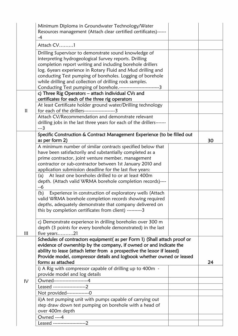
Minimum Diploma in Groundwater Technology/Water
Resources management (Attach clear certified certificates)------
-4
Attach CV………1
Drilling Supervisor to demonstrate sound knowledge of
interpreting hydrogeological Survey reports. Drilling
completion report writing and including borehole drillers
log. 6years experience in Rotary Fluid and Mud drilling and
conducting Test pumping of boreholes. Logging of borehole
while drilling and collection of drilling rock samples.
Conducting Test pumping of borehole.---------------------------3
II
c) Three Rig Operators – attach individual CVs and
certificates for each of the three rig operators
At least Certificate holder ground water/Drilling technology
for each of the drillers---------------------3
Attach CV/Recommendation and demonstrate relevant
drilling jobs in the last three years for each of the drillers-------
---3
III
Specific Construction & Contract Management Experience (to be filled out
as per form 2) 30
A minimum number of similar contracts specified below that
have been satisfactorily and substantially completed as a
prime contractor, joint venture member, management
contractor or sub-contractor between 1st January 2010 and
application submission deadline for the last five years:
(a) At least one boreholes drilled to or at least 400m
depth. (Attach valid WRMA borehole completion records)----
--6
(b) Experience in construction of exploratory wells (Attach
valid WRMA borehole completion records showing required
depths, adequately demonstrate that company delivered on
this by completion certificates from client) ----------3
c) Demonstrate experience in drilling boreholes over 300 m
depth (3 points for every borehole demonstrated) in the last
five years……….21
IV
Schedules of contractors equipment( as per Form 1) (Shall attach proof or
evidence of ownership by the company, if owned or and indicate the
ability to lease (attach letter from a prospective the lessor if leased)
Provide model, compressor details and logbook whether owned or leased
forms as attached 24
i) A Rig with compressor capable of drilling up to 400m -
provide model and log details
Owned-----------------------4
Leased ----------------------2
Not provided---------------0
ii)A test pumping unit with pumps capable of carrying out
step draw down test pumping on borehole with a head of
over 400m depth
Owned ----4
Leased ----------------------2

Not provided---------------0
iii)A dip meter(dipper) capable of measuring up to 400 m
head water levels
Owned ------4
Leased -------------------------------2
Not provided-------------------------0
iv)Logging equipment capable of undertaking geophysical
logging for electric logging and gamma logging up to
400metres depth.
Owned -----------------------------4
Leased -----------------------------2
Not provided----------------------0
v)A borehole camera capable of 400 metres of depth filming
Owned --------------------4
Leased -----------------------------2
Not provided----------------------0
vii) EC meter
Owned --------------------4
Leased -----------------------------2
Not provided----------------------0
V
Annual audited financial reports (last three (3) years) 10
At least one of the annual turnover greater or equal to the
cost of the project 10
Annual turn-over below the cost of the project 2
VI
Evidence of financial resources (cash in hand, lines of credit, overdraft
facility etc give proof of availability) 10
Cash in hand and lines of credit:
Of more than 30% of tender sum 10
Of between 20% and 30% of tender sum 7
Of between 10% and 20% of tender sum 4
Below 10% of tender sum 2
TOTAL SCORE 100

TECHNICAL SPECIFICATIONS AND FORM BILLS OF QUANTITIES FOR
PROPOSED ONE(1 NO.) EXPLORATORY BOREHOLE AT ENDEMBESS,
KITALE TRANS NZOIA COUNTY LOT 2
Table of Contents
GENERAL ......................................................................................................................................... 31
1 Introduction ........................................................................................................................ 31
2 Objective of works ............................................................................................................ 31
3 Supervision of works ......................................................................................................... 31
4 Description of the Contractor/ works ........................................................................... 31
Borehole construction ........................................................................................................... 31
Borehole pumping test ........................................................................................................... 32
5 Programme of works ........................................................................................................ 32
6 Location of the works ....................................................................................................... 32
7 Bills of quantity .................................................................................................................. 33
8 Site access and permits ...................................................................................................... 33
9 Provision of equipment, materials and labour .............................................................. 33
10 Personnel on site ................................................................................................................. 34
11 Diligent performance ......................................................................................................... 34
12 Lost bore .............................................................................................................................. 35
13 Mobilisation, demobilisation and site restitution – drilling plant .............................. 35
Description .............................................................................................................................. 35
Rates ......................................................................................................................................... 35
Drilling ..................................................................................................................................... 36
A) drilling with air/foam ....................................................................................................... 36
Rates ......................................................................................................................................... 36
14 Supply and installation of temporary / surface casing ................................................. 37
Description .............................................................................................................................. 37
Rates ......................................................................................................................................... 37
Description .............................................................................................................................. 37
Rates ......................................................................................................................................... 38
15 Geophysical Logging.......................................................................................................... 38
22 Abandonment if dry ...................................................................................................... 39
Description .............................................................................................................................. 39

Rates ......................................................................................................................................... 39
23 Supply and installation of permanent casing and screen ......................................... 39
Casing and screen specification ............................................................................................ 39
Casing and screen installation .............................................................................................. 39
Rates ......................................................................................................................................... 40
24 Supply and installation of gravel pack ........................................................................ 40
Gravel pack specification ....................................................................................................... 40
Gravel pack installation ........................................................................................................ 40
Rates ......................................................................................................................................... 41
25 Installation of backfill .................................................................................................... 41
Description .............................................................................................................................. 41
Rates ......................................................................................................................................... 41
26 Grout ................................................................................................................................ 41
Description .............................................................................................................................. 41
Grout specification and installation .................................................................................... 41
Rates ......................................................................................................................................... 41
27 Development .................................................................................................................. 42
Physical development ........................................................................................................... 42
Chemical development ......................................................................................................... 42
Rates ......................................................................................................................................... 43
28 Borehole Testing............................................................................................................. 43
Introduction ............................................................................................................................ 43
Installation, plant and methodology .................................................................................. 43
a. Pumping plant ....................................................................................................... 43
b. Pre-test .................................................................................................................... 45
c. Step-drawdown test.............................................................................................. 45
d. Constant discharge test ......................................................................................... 45
e. Recovery test and removal of plant .................................................................. 45
Rates ......................................................................................................................................... 45
29 Water sampling and analysis ........................................................................................ 46
Analysis specification ............................................................................................................. 46
Rates ......................................................................................................................................... 47
30 Borehole headworks ...................................................................................................... 47
Headworks specification ....................................................................................................... 47

Rates ......................................................................................................................................... 47
31 Borehole cap ....................................................................................................................... 47
Borehole cap specification .................................................................................................... 47
Rates ......................................................................................................................................... 48
32 Records and reporting ................................................................................................... 48
Description .............................................................................................................................. 48
Rates ......................................................................................................................................... 48
Borehole Camera Video Log................................................................................................ 48
GENERAL ........................................................................................................................................... 4
1 Introduction .......................................................................................................................... 4
2 Objective of works .............................................................................................................. 4
3 Supervision of works ........................................................................................................... 4
4 Description of the Contractor/ works ............................................................................. 4
Borehole construction ............................................................................................................. 5
Borehole pumping test ............................................................................................................. 5
5 Programme of works .......................................................................................................... 5
6 Location of the works ......................................................................................................... 6
7 Bills of quantity .................................................................................................................... 6
8 Site access and permits ........................................................................................................ 6
9 Provision of equipment, materials and labour ................................................................ 7
10 Personnel on site ................................................................................................................... 8
11 Diligent performance ........................................................................................................... 8
12 Lost bore ................................................................................................................................ 8
13 TECHNICAL SPECIFICATION, EXPLORATION/PRODUCTION BOREHOLES ............... 10
14 Mobilisation, demobilisation and site restitution – drilling plant .............................. 10
Description .............................................................................................................................. 10
Rates ......................................................................................................................................... 10
Drilling ..................................................................................................................................... 10
A) drilling with air/foam ....................................................................................................... 11
Rates ......................................................................................................................................... 11
15 Supply and installation of temporary / surface casing ................................................. 12
Description .............................................................................................................................. 12
Rates ......................................................................................................................................... 12
Description .............................................................................................................................. 12

Rates ......................................................................................................................................... 12
16 Geophysical Logging.......................................................................................................... 13
23 Abandonment if dry ...................................................................................................... 14
Description .............................................................................................................................. 14
Rates ......................................................................................................................................... 14
24 Supply and installation of permanent casing and screen ......................................... 14
Casing and screen specification ............................................................................................ 14
Casing and screen installation .............................................................................................. 14
Rates ......................................................................................................................................... 15
25 Supply and installation of gravel pack ........................................................................ 15
Gravel pack specification ....................................................................................................... 15
Gravel pack installation ........................................................................................................ 15
Rates ......................................................................................................................................... 16
26 Installation of backfill .................................................................................................... 16
Description .............................................................................................................................. 16
Rates ......................................................................................................................................... 16
27 Grout ................................................................................................................................ 16
Description .............................................................................................................................. 16
Grout specification and installation .................................................................................... 16
Rates ......................................................................................................................................... 17
28 Development .................................................................................................................. 17
Physical development ........................................................................................................... 17
Chemical development ......................................................................................................... 17
Rates ......................................................................................................................................... 18
29 Borehole Testing............................................................................................................. 18
Introduction ............................................................................................................................ 18
Installation, plant and methodology .................................................................................. 18
a. Pumping plant ....................................................................................................... 18
b. Pre-test .................................................................................................................... 20
c. Step-drawdown test.............................................................................................. 20
d. Constant discharge test ......................................................................................... 20
e. Recovery test and removal of plant .................................................................. 20
Rates ......................................................................................................................................... 21
30 Water sampling and analysis ........................................................................................ 21

Analysis specification ............................................................................................................. 21
Rates ......................................................................................................................................... 22
31 Borehole headworks .......................................................................................................... 22
Headworks specification ....................................................................................................... 22
Rates ......................................................................................................................................... 22
32 Borehole cap ................................................................................................................... 23
Borehole cap specification .................................................................................................... 23
Rates ......................................................................................................................................... 23
33 Records and reporting ................................................................................................... 23
Description .............................................................................................................................. 23
Rates ......................................................................................................................................... 23
Borehole Camera Video Log................................................................................................ 24
.

4
GENERAL
1 Introduction
This Technical Specification describes in outlines the specification for one
borehole proposed to be drilled in Endembess area in Trans Nzoia County (see
table 1).
2 Objective of works
The objective of these works is to construct one (1) exploratory 203mm (8”)
boreholes with the a im of col lect ing data to enhance knowledge of
groundwater in the aquifers in th i s area. The data to be col lected
inc ludes logs of the s t rata, geophys ic a l log of the borehole,
pumping test data, water qual i ty data .
Authorisations will be provided AT the respective Water Resources Authority
(WRA) Office (Kitale Sub Region Office).
).
3 Supervision of works
The WRA shall appoint its own supervisor or inspector to monitor the conduct
of the works, who will be the client’s representative for the site. The Drilling
contractor shall have a hydrogeologist should be a licensed water resource
professional with a valid license in 2019. He/she will also demonstrate
professional qualifications degree certificate in Geology or any groundwater
related degree.
WRA will inspect plant and personnel proposed by any Contractor for
deployment for the works prior to the award of contract.
4 Description of the Contractor/ works
The driller of the works should fulfill statutory registrations as a contractor of
similar works. The firm should have a valid license for the year 2019 from the
Ministry of Water &Sanitation and Irrigation and National Construction
Authority and all such condition as will be set out by the Authority towards this
work.
The Contractor shall mobilise both drilling and test plant and all related
equipment to ensure their availability to undertake the works. The process shall

5
be as follows:-
Borehole construction
1. Mobilise and Drill a borehole to a depth of 400 m at a diameter of not
less than 203 mm (8”), unless directed by the Supervising Hydrogeologist
to stop drilling at a shallower depth.
2. Collect samples at every 2 metres and lay them out as per the Code of
practice for the construction of a borehole (section 4.2)
3. Examine and record in the relevant forms the collected samples
description as per the Code of practice for the supervision of
construction and test pumping of boreholes (sections 4 and the referred
forms)
Provided significant groundwater is encountered the following activities will
apply-:
4. Supply and install 152 mm (6”) steel casing and screen, gravel pack and
inert backfill. If a shallow saline or brackish aquifer is encountered, this
may be sealed off with grout if so instructed by the supervising
hydrogeologist.
5. Develop the productive borehole.
6. Disinfect the productive borehole.
7. Carry out electrical(resistivity) and gamma logging.
8. Construct the borehole headworks as described further in this document.
9. Carry out down the hole filming using a Borehole Camera.
Borehole pumping test
6. Mobilise test pumping plant to the site and set up at the borehole to be
tested (as instructed by the Supervising hydrogeologist).
7. Install test pumping plant and conduct pumping and recovery tests in the
first borehole to be tested.
8. Sample and have the pumped water analysed for chemical and
bacteriological parameters from the borehole at the WRA Central Water
Testing Laboratory.
9. Remove test pumping plant.
10. Install well cap that is tamper proof till the works are commissioned.
This outline programme are changeable: in the event that boreholes are either
dry or produce water of insufficient quantity or unacceptable salinity, it is likely
that boreholes will not be subjected to testing.
5 Programme of works
The Contractor shall provide the Supervising hydrogeologist with a detailed
Programme of Works within seven days of site handover to be drilled and the
order in which they will be drilled. This Programme shall be mutually agreed.

6
It shall include both a logistic and a communication plan. These shall
thereafter be deemed the Agreed Programme. The Contractor shall adhere
strictly to the Agreed Programme unless otherwise authorised by the
Supervising hydrogeologist in writing or by other mutually approved
method.
This shall exclude Acts of God, Force Majeure and other unavoidable events,
but shall not exclude delays arising from mechanical plant breakdown, labour
disputes or failure to ensure that water is available on site for drilling. Acts of
God explicitly exclude normal rains. Unauthorised departure from the Agreed
Programme may incur liquidated damages.
6 Location of the works
Boreholes will be drilled in sites selected as follows in Trans Nzoia County
Table 1
SITE NAME LOCATION FORMATIO
N
GEOGRAPHICAL
COORDINATES
COUNTY
Endembess
area
Endembess
Area Volcanic
Latitude 1.0806310N,
longitude 34.85850E.
Trans Nzoia
Contractors should note that access to sites is on rural access roads that are in
variable condition; however, we foresee no specific problems facing
mobilisation under normal conditions with plant in normal working condition.
The Client shall make available a working area of not less than 30 x 30 m
prior to drilling plant arriving on site.
7 Bills of quantity
The Items and Rates given by the Contractor are deemed the Bills of Quantity
that shall apply to these works.
Payments will be made according to the actual depth drilled, materials
installed and works, and tests undertaken, except where errors are the
responsibility of the Contractor.
8 Site access and permits
The Client will obtain all necessary permits and authorisations. Copies of all

7
documentation required by the Water Resources Management Rules, 2007 will
be handed over to the Contractor as will the EIA Licence (if relevant).
9 Provision of equipment, materials and labour
The Contractor shall provide all equipment, transport, materials consumables
and labour necessary for the satisfactory completion of the Works in compliance
with this Specification. Direct rotary plant shall be deployed, capable of drilling
a borehole to a depth of 450 m at a diameter of not less than 254 mm (10”) in
basalts, volcano clastic sediments, old land surfaces and weathered and fresh
Basement rock.
Bidders must be able to deploy both air (down-the-hole hammer) and fluid
flush drilling equipment for these works. The most appropriate method will be
left to the drilling contractor to decide, after consultation with the Supervising
hydrogeologist.
When bidding, Contractors shall provide full specifications of all plant to be
deployed for these Works, including all downhole drilling and fishing tools
(including a Schedule of bits, stabilisers, subs, crossovers etc). The Supervising
hydrogeologist will inspect plant and materials prior to mobilisation and may
reject plant or material that in his view is sub-standard or inappropriate.
The bidder will also provide full specifications of the electrical logger and
borehole Camera. The electrical logger and borehole camera should be
appropriate to log or film to a maximum depth of 400m.
Bidders shall present method statements in their Proposal describing in detail the
proposed approach to these works, in which respect his attention is drawn to the
need to describe their proposed approach to the following: –
1. Logistic train available to support the works; this shall include all haulage
plant and the specification of all drilling, development, testing and associated
plant; and the Schedule of bits, stabilisers subs, crossovers etc proposed for
deployment to site;
2. Proposed borehole drilling approach, including measures to overcome
setbacks that may be
encountered during drilling (including but not limited to collapse of
geological material);
3. Proposed approach to reaming (if proposed), including measures to
overcome setbacks that may be encountered during reaming (if applicable);
4. Proposed approach to the completion of the drilled borehole as a
production borehole, including specifications of casing, screen and gravel pack;
proposed casing attachment method (e.g. butt- welding or ring-welding, etc
…);
5. Proposed development methodology or methodologies.
6. Confirmation of intention to comply with BS 6316 (1992) or the draft Kenya
Code of Practice for the Test Pumping of Boreholes in respect of all pumping

8
and recovery tests; or by providing a detailed description of the proposed
approach to conducting constant discharge and recovery tests;
10 Personnel on site
The Contractor shall provide summary details of the experience of key
personnel to be deployed for these Works, in the form of short curricula vita
for each of the principal drill team members, in particular the Hydrogeologist,
Drilling Supervisor, and three Dr i l ler s .
Elements which are considered of particular importance are years of drill team
experience in deep borehole construction in volcanic, basement and
alluvial/sedimentary formations both in the County and elsewhere in Kenya
as well as relevant professional qualifications. Demonstrated experience in
the logistic support of remote sites is also clearly advantageous.
11 Diligent performance
The Contractor shall at all times perform the Works diligently and in accordance
with sound professional practice. The Contractor shall not proceed from one
stage of works to another without the express permission of the Supervising
Hydrogeologist.
Decisions regarding discontinuing any element or part of any element of these
works, or abandonment of these works, shall be discussed jointly between the
Contractor and the Supervising Hydrogeologist before any further actions are
authorised by the Supervising Hydrogeologist. The Supervising Hydrogeologist’s
decision shall be final and shall be given in writing.
The Supervising Hydrogeologist will require a written submission justifying
any steps taken or works conducted by the Contractor made without the
Supervising Hydrogeologist’s approval. An unsatisfactory explanation shall lead
to non- payment for works undertaken without prior agreement and may be
taken into consideration for inclusion as liquidated damages.
12 Lost bore
If the Contractor is unable to finish drilling or has to abandon a well due to the
loss of tools or any other accident or contingency that is his responsibility, the
borehole will be deemed a Lost Bore. This includes his equipment not able to
drill through any formation, it is deemed that if offered this work the plant is
capable of drilling through any formation. The Contractor shall remove all
casing or drill pipe already placed in the hole where this is possible and plug it
to surface at his own expense. All material remaining in and removed from the
hole will remain the property of the Contractor. In such a case the Client shall

9
not pay for any of the work carried out and will authorise in advance the
drilling of a new hole at a site near the abandoned one, after consultation with
the Water Resources Authority.
In the event that a successfully-drilled borehole is deemed by the Supervising
Hydrogeologist to be dry or is of unacceptable salinity and should be
abandoned, the Contractor shall be paid for all works associated with its
drilling and abandonment and the designation Lost Bore shall not apply.

10
13 TECHNICAL SPECIFICATION, EXPLORATION/PRODUCTION BOREHOLES
Only One (1) borehole shall be constructed. The precise sites on which the boreholes
will be constructed will be shown to the Contractor by the Client or the Client’s
representative; the Contractor shall not commence setup or drilling at an unapproved
site; should he do so, all costs shall be deemed his own. All necessary permits and
authorisations will have been issued and will be made available to the Contractor
prior to mobilisation.
14 Mobilisation, demobilisation and site restitution – drilling plant
Description
The Contractor shall mobilise his drilling plant to the drill site in accordance with the
Agreed Programme. Mobilisation is deemed to include the erection, dismantling,
preparation of the drill site area and its restitution after the completion of all works;
and erection and removal of a temporary camp at the site indicated by the Client
should this be required.
On completion of works, the site shall be cleaned, and surplus material removed to
the satisfaction of the Supervising Hydrogeologist. Site re-instatement includes the
removal off-site of all hydrocarbons changed, spilled, leaked or otherwise released,
all packaging and cotton waste.
The Contractor shall make his own arrangements for the collection and transport of
water for drilling and camp purposes.
Rates
The Contractor shall provide: –
- A lump sum price for mobilisation and demobilisation of drilling plant, site re-
instatement, and camp, including setting up, commencing at the site.
- A lump sum price for the borehole for water provision and haulage
Drilling
Description
Boreholes shall be drilled at a diameter of not less than 203mm (8”) to allow the safe
installation of
152 mm (6”) production casing and screen, to a depth not greater than 450m.
The Contractor shall provide plant capable of drilling to a depth of 450m at a
diameter of 254mm (10”).
The Contractor shall be responsible for the drilling method or methods selected, and
neither the Client nor the Supervising Hydrogeologist shall be held responsible should
the method or methods adopted fail in the objective of drilling to a depth of at least
450 m.

11
With rotary methods the Contractor shall not use excessive pulldown on the bit.
Should the borehole be skewed as a result of excessive pulldown, and the borehole
not fit for purpose in consequence, the hole shall be deemed a Lost Bore. The
Contractor is required to deploy a stabiliser/drill collar of appropriate diameter when
drilling; the following table presents acceptable ranges for stabilisers/drill collars for
different borehole diameters: –
Drilling diameter, inches Recommended stabiliser diameter (range), inches
6½” 4¾” – 5”
8½” 6½” – 6¾”
9½” 6” – 7¼”
11” 8¼” – 9½”
A) drilling with air/foam
Foam used for hammer drilling and additives used for fluid rotary flush drilling must
be suited to environmental applications. The Contractor shall be responsible for
ensuring that the additives deployed are suitable for such conditions and shall furnish
the specification of all proposed additives with his proposal.
B) drilling with fluid flush
Fluid additives of bentonitic type will not be acceptable for use in these works: if fluid
rotary flush methods are to be adopted, either cellulose-based reconstituted powder
or artificial liquid anionic polymeric additives will be used for viscosity enhancement.
The Contractor will state the type and manufacturer of additive(s) to be used and will
describe the means by which the additive(s) will be mixed. The judicious application
of bentonite and cellulose or similar material will be acceptable as a means of
preventing loss of circulation in those parts of the borehole located above the aquifer
zone, though their use must be authorised in advance by the Supervising
Hydrogeologist.
Rates
The Contractor shall provide unit prices for the following: –
A: drilling with air/foam
- Drilling at a diameter to accommodate surface casing (per metre) (provisionally 12m);
- Drilling at 203mm (8”) from the depth to which surface casing has been installed to
100mbgl (per
metre), provisional total 88 m;
- Drilling at 203 mm (8”) from 100 to 400 (per metre)
B: drilling with fluid flush
- Drilling at a diameter to accommodate surface casing (per metre) (provisionally 12m);
- Drilling at 203mm (8”) from the depth to which surface casing has been installed to
100mbgl (per
metre), provisional total 88m.
- Drilling at 203 mm (8”) from 100 to 400mbgl (per metre),

12
15 Supply and installation of temporary / surface casing
Description
Boreholes may require temporary casing to protect the wellhead from cavitation
while drilling at greater depths. The Contractor should allow for not less than three
(3) metres of temporary casing per borehole, though the Supervising Hydrogeologist
may require surface casing to be installed to depths greater than this, and the
Contractor must ensure that sufficient temporary casing is deployed to site to allow
installation to greater depths. Casing used as surface casing shall be new mild steel of
a specification suited to water well applications for installation to depths not
exceeding 5 m depth; the specification shall be given in the Contractor’s Proposal.
Rates
The Contractor shall provide unit prices for the following: –
- Supply/install/remove temporary / surface casing (per metre; rate only);
- Supply/install temporary / surface casing (per metre; rate only).
The provisional total for temporary / surface casing is 12
metres.
Sample collection and storage, and record keeping
Description
Geological samples of dry weight 500 g shall be collected at 2 m intervals and at
prominent lithological boundaries. These are to be sun- or oven-dried, packed in
polythene bags or bottles of appropriate size, and clearly marked with tie-on labels
indicating date of collection, depth interval and borehole name and number. These
will be analysed on site by the Supervising Hydrogeologist.
The Contractor shall record the depth of any zone of lost circulation for which no
sample was taken.
A log of the rate of penetration, in minutes per metre drilled, shall be kept. The
depth of any voids, or of particularly rapid penetration, or significant changes in rig
noise indicating changes in geological conditions, shall also be noted.
Water levels shall be measured and recorded at the start and end of every shift, after
significant breaks in activity (such as meal breaks), and during periods of plant
downtime (as appropriate), and as required by the Water Act 2016 (Fourth Schedule).
Water levels shall be measured using a sounding and/or lighting dipper approved in
advance by the Supervising Hydrogeologist. One (1) fully functional dipper, complete
with spares batteries, bulbs or buzzers (as appropriate), shall be deployed with the
drilling rig throughout drilling operations. The Supervising Hydrogeologist will check
that the dipper meets the required standard.
Rates

13
The Contractor shall provide a unit rate for the collection, drying and packaging of
samples, which shall include the collection of water level data during the drilling
process.
There shall be a provisional maximum of 200 samples generated during the
drilling programme, assuming that the full metreage is drilled. The number of
water level measurements that shall be collected cannot be anticipated.
16 Geophysical Logging
4. The successful bidder will conduct electrical downhole geophysical logging of all
boreholes, for all parts of each borehole that are saturated. It is acknowledged that this
may require more than a single pass in any one borehole.
5. The electric log will be collected at 1 metre intervals, with the following data
required by the logging process: -
17 Self-potential (in all cases SP shall be measured during the first instrument run, down
the borehole)
18 Temperature (again, measured during the first run)
19 Fluid resistivity (again, measured during the first run)
20 Short-normal resistivity
21 Long-normal resistivity
22 Lateralog (resistivity)
6. Bidders shall provide: –
b) A unit measurement rate for running logs, multiple pass. Thus for a 250 m-deep
borehole, the net run will cover 250 measurement sets (each comprising one each
for the six parameters listed at 2. above). The maximum possible total number of
logging points will be 400m in the borehole; however, as measurements cannot be
made in unsaturated sections of boreholes, the actual total will be less than this.
.
The contractor shall carry out the required operations by personnel skilled both
in conducting the
measurements and the interpretation of the results. The operation shall be as
follows
f. Electric logging shall be conducted in uncased boreholes upon completion
of the drilling of the pilot holes (before reaming).
g. Gamma logging
h. The drilled hole shall be cleaned by circulation of drilling fluid and its
depth measured.
i. The electrode cables shall be lowered into the borehole while at the same
time measuring the depth.
j. The logs shall be taken from the bottom of the borehole upwards while
the cable is taut over its entire length.
Upon completion of all operations the contractor shall provide the Supervising
Hydrogeologist with the electric logs comprised of SP cure and R curve, together
with their interpretation. Should the Supervising Hydrogeologist refuse to accept
the results of the logging because of technical faults then the contractor shall
repeat the measurement until satisfactory results are obtained.

14
The logging data should be presented in a good practice format.
23 Abandonment if dry
Description
If the borehole is deemed “dry” by the Supervising Hydrogeologist (which may
simply indicate that insufficient water has been encountered to justify completion
as a production borehole, or that saline water has been encountered), he shall
instruct that all surface casing be removed from the borehole, and that the
borehole be backfilled with drill cuttings to 2 m bgl. From 2 m bgl to ground
level a 1: 2 OPC: sand grout plug will be installed (for specification see S. 2.9.1).
Set into the top of this plug shall be a mild steel plate, on which the WRMA
Authorisation number shall be inscribed or written in weld-metal.
Rates
The Contractor shall be paid for all works associated with drilling and making safe
an abandoned borehole. The Contractor shall provide unit prices for the
following: –
- Backfilling with drill cuttings (per linear metre: rate only);
- Grouting from 2 m bgl to ground level and provision of a steel plate with borehole
identification
number to be set into grout (lump sum; rate
only).
24 Supply and installation of permanent casing and screen
Casing and screen specification
Casing shall be new 152 mm (6”) internal diameter mild steel of a specification
suited to water well applications in boreholes of up to 400m depth.
Screens shall comprise mild steel 152mm (6”) diameter screen with plasma-cut slots of
size 1.0 mm in width, with an open area of not less than 6%. Slots cut with an oxy-
acetylene gas torch will not be acceptable. The Contractor will provide open area
and column strength information in his Proposal.
Casing and screen installation
Before installation of casing and screen the hole shall be shown clear to design depth
and diameter; if not clear the hole shall be flushed to remove any backfilled material
present.
Where casing and screen are to be welded the appropriate welding electrodes shall be
used. Welding shall proceed only when the casing or screen length is demonstrated to
be vertical. Care shall be taken to ensure that all oxide coating is removed between
welding passes, and to avoid any burn-through or deposition of weld on the inside of
the casing or screen.
The base of the casing string shall probably be blinded. The decision as to whether it

15
is left open or sealed will be finalised during the borehole design stage by the
Supervising Hydrogeologist. Blinding may comprise either a pointed or a flat closure,
at the discretion of the Contractor and with the approval of the Supervising
Hydrogeologist. The closure shall entirely seal the casing string and shall be
constructed of mild steel. The Supervising Hydrogeologist will consider alternative
means by which casing bottom blinding may be achieved, including running a steel
slug packer into the casing string after installation to design depth; or by running a
grout into the base of the borehole. Should the Contractor propose alternatives, he
shall describe the method in appropriate detail in his Proposal.
The top of the casing string at completion of construction shall terminate not less
than 0.35 m above original ground level.
Rates
The Contractor shall provide unit prices for the following: –
- Supply/install mild steel plain casing (per metre);
- Supply/install mild steel screen (per metre).
25 Supply and installation of gravel pack
Gravel pack specification
The Contractor shall supply and install filter pack/formation stabiliser. Material shall
be 2-4 mm diameter, clean well-rounded siliceous gravel with no more than 5%
non-siliceous material. The Contractor shall provide in his Proposal a particle size
distribution curve from a reputable laboratory describing the gravel pack he
proposes to install, as well as the bulk density of the pack material expressed as kg
per m3.
The pack shall be inspected by the Supervising Hydrogeologist on site, and if it is
excessively dirty, he will require that it be washed to his satisfaction, before approving
its installation into the borehole annular space; the costs associated with such washing
on site shall be met by the Contractor, and the time spent doing so will be accounted
as down-time.
Gravel pack installation
Installation of gravel pack/formation stabiliser may use water washdown or reverse
circulation methods. In the latter case a pump set or airlift string shall be installed in
the borehole so as to encourage material settlement. 65% chlorine granular calcium
hypochlorite will be introduced into the annular space along with the pack material at
a nominal concentration of 500 grammes per cubic metre of pack. This will break
down any residual additive(s) (if used) and will disinfect the wellbore.
The filter pack shall terminate not less than 10 m above the uppermost screen when
stabilised, or as otherwise directed by the Supervising Hydrogeologist. The contractor
shall describe how he proposes to measure the level of gravel pack.

16
Rates
The Contractor shall provide a unit volume price for the supply and installation
of gravel pack, inclusive of washdown or reverse circulation, and granular
calcium hypochlorite.
26 Installation of backfill
Description
Backfill material shall comprise fine or clayey drill cuttings and shall be installed from
the top of the filter pack to 3 m bgl or as otherwise directed by the Supervising
Hydrogeologist. The installation method must ensure that no bridging occurs within
the annular space. The Contractor shall measure the depth to the top of the backfill
and provide the means by which this level shall be measured.
Rates
The Contractor shall provide a unit linear metre price for the installation of inert
backfill. Bidders must bear in mind that the installation of backfill is a simple manual
job. If the linear meter rate for manual backfilling
exceeds that offered for day rate (manpower), then the latter rate may be used on a
pro-rata basis should the Supervising Hydrogeologist consider the cost saving to be
significant.
27 Grout
Description
In the event that a saline aquifer is encountered at any depth, the Supervising
Hydrogeologist shall instruct the Contractor to install a cement grout that shall
effectively and permanently seal the aquifer from the casing string and vertical
percolation.
In any event the Contractor shall install a cement grout as a sanitary seal at the
wellhead, which shall be installed from 3 m bgl to ground level.
Grout specification and installation
Grout shall comprise a cement/fine siliceous sand mixture in the ratio 1: 2, mixed
with just enough water that it can be poured (it should have a slurry weight not
less than 1.6 kg/l), which shall be
installed from the top of the inert backfill to ground level or as otherwise directed by
the Supervising Hydrogeologist. The installation method must ensure that no bridging
occurs within the annular space. The Contractor shall measure the distance to the top
of the grout from time to time and provide the means by which this level shall be
measured. The installation method and the means of measurement will be described in
the Proposal.
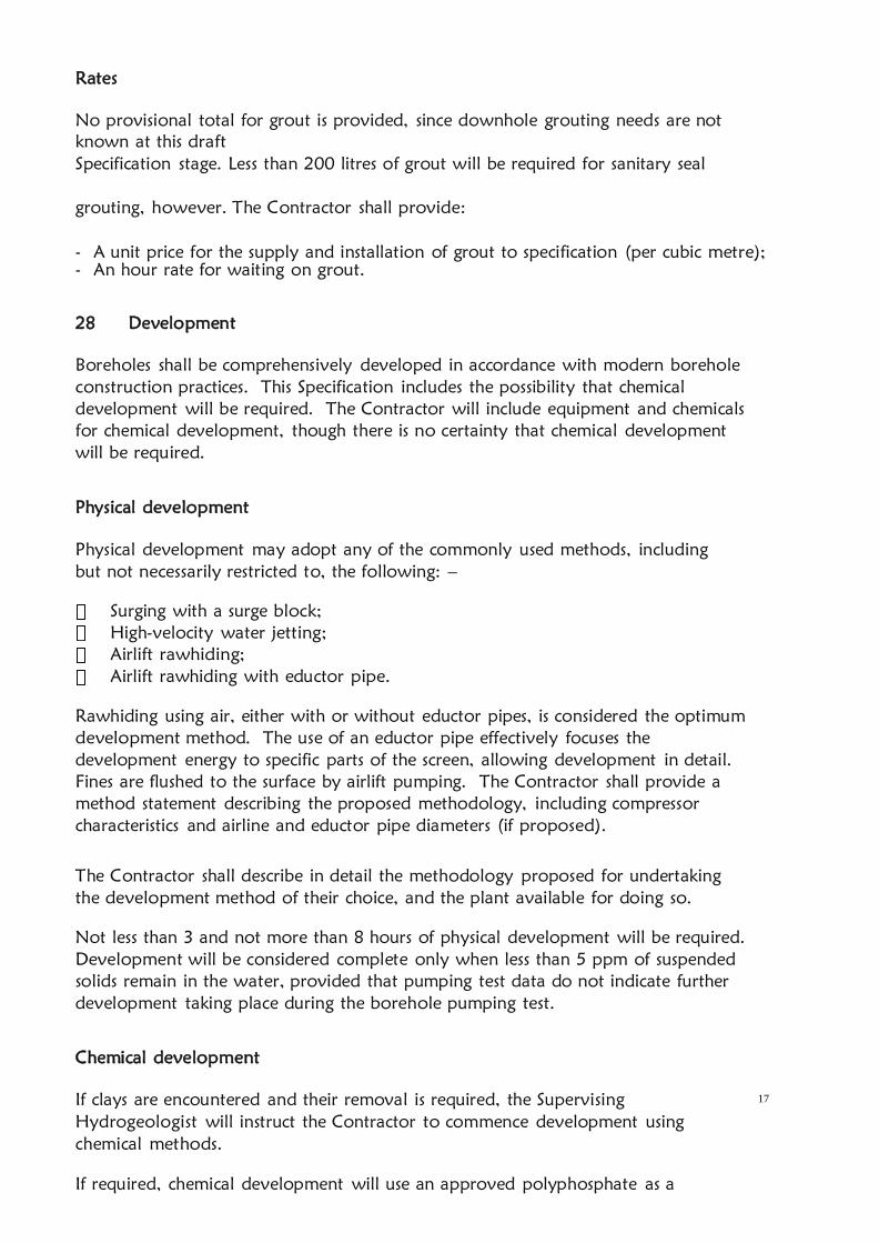
17
Rates
No provisional total for grout is provided, since downhole grouting needs are not
known at this draft
Specification stage. Less than 200 litres of grout will be required for sanitary seal
grouting, however. The Contractor shall provide:
- A unit price for the supply and installation of grout to specification (per cubic metre);
- An hour rate for waiting on grout.
28 Development
Boreholes shall be comprehensively developed in accordance with modern borehole
construction practices. This Specification includes the possibility that chemical
development will be required. The Contractor will include equipment and chemicals
for chemical development, though there is no certainty that chemical development
will be required.
Physical development
Physical development may adopt any of the commonly used methods, including
but not necessarily restricted to, the following: –
Surging with a surge block;
High-velocity water jetting;
Airlift rawhiding;
Airlift rawhiding with eductor pipe.
Rawhiding using air, either with or without eductor pipes, is considered the optimum
development method. The use of an eductor pipe effectively focuses the
development energy to specific parts of the screen, allowing development in detail.
Fines are flushed to the surface by airlift pumping. The Contractor shall provide a
method statement describing the proposed methodology, including compressor
characteristics and airline and eductor pipe diameters (if proposed).
The Contractor shall describe in detail the methodology proposed for undertaking
the development method of their choice, and the plant available for doing so.
Not less than 3 and not more than 8 hours of physical development will be required.
Development will be considered complete only when less than 5 ppm of suspended
solids remain in the water, provided that pumping test data do not indicate further
development taking place during the borehole pumping test.
Chemical development
If clays are encountered and their removal is required, the Supervising
Hydrogeologist will instruct the Contractor to commence development using
chemical methods.
If required, chemical development will use an approved polyphosphate as a

18
disaggregant that shall break down clays, silts, or other fine material adjacent to the
wellbore. Consideration shall be given to the geological log when dosing; where clays
are abundant the over-application of polyphosphate can lead to sloughing of
geological material and may damage the borehole.
The decision as to whether chemical development shall be adopted, and at what
dosage rates, shall be made by the Supervising Hydrogeologist on the basis of
observations made during drilling and sample logging.
Rates
The Contractor shall provide unit prices for the following: –
- Physical development (per hour) – this explicitly refers to development time,
and excludes the time taken for installation/removal of development tools which
shall be costed into the development rate;
- Chemical development (each chemical development exercise; rate
only), inclusive of installation/removal of development tools.
Provisionally, there shall not be more than 40 hours of physical development. Bidders
should allow for not less than five (5) chemical development cycles.
29 Borehole Testing
Introduction
The boreholes shall be tested in accordance with modern practices. Borehole testing
shall be conducted
Kenya Code of Practice for the Test Pumping of Boreholes or an acceptable equivalent
and relevant forms filled. The following elements shall be required:–
a) A pre-test.
b) A 10-hour step-drawdown
test.
c) A constant discharge test for 24
hours.
d) A recovery test.
The step-drawdown and constant discharge tests shall be timed so as to begin in the
morning, in order that the frequent early test time measurements are made during
daylight hours.
Installation, plant and methodology
Pumping plant and dipping tube shall be installed in the borehole. The
Supervising Hydrogeologist shall specify anticipated discharge and pump intake
depth.
a. Pumping plant
Pumps used for testing may be electric submersible, surface-mounted turbine, or
reciprocating pumps. Intake depth shall be suitable to capture the boreholes dynamic

19
water levels as the pumping is going on. Any pump used in tests shall have a fully
functioning non-return valve either in the pump itself or in the rising main
immediately above the top of the pump.
Discharges are expected to be in the range of at least 3 to 30 m3/hr at least dynamic
heads of 50 to 300 metres or what is applicable to the borehole situation and the
Contractor shall have at his disposal pumps and appropriate power generation plant
covering this discharge and head range. Bidders shall provide the specification
(manufacturer, designation and performance curves) for the pumps they propose to
deploy for these works as a part of their Proposal.
Rising main pipe shall be of a material suitable for installation depths to a minimum of
300 metres. The water pumped from the borehole shall be discharged to waste at a
distance not less than 10 metres from the wellhead or as otherwise approved by the
Supervising Hydrogeologist, and in such a manner that it does not flow back towards
the borehole.
A generator or other prime mover shall be provided for powering the pump; the
power source shall be able to provide motive power without stopping for any reason,
for a continuous period of not less than
30 hours. Weatherproofing for the prime mover and the wellhead area, such that
rain will not prevent tests from being undertaken, shall also be provided.
Any failure to adequately weatherproof prime moving plant or any mechanical
failure leading to the abandonment of tests will be at the Contractor’s cost, as
abandoned tests will not be paid for. Furthermore, the Client shall hold back from
payment any costs incurred by himself in respect of additional site time costs
incurred by the Supervising Hydrogeologist for this reason.
(i) Discharge measurement and control
Discharge measurement shall be by an approved accurate method, such as an
orifice plate, calibrated flow meter, V-notch weir or using a volumetric method.
If volumetric methods are proposed, the Contractor will ensure that the container to
be used has been calibrated and set absolutely horizontally; each discharge
measurement shall be calculated from the average of not less than three time
measurements, or as otherwise approved by the Supervising Hydrogeologist. The base
on which the calibrated container is supported during measurement shall be
horizontal, and the Contractor will be required to demonstrate this to the Supervising
Hydrogeologist’s satisfaction at any time before and during tests.
Discharge shall vary by not more than 15% across the constant discharge test, except
when otherwise approved by the Supervising Hydrogeologist. If unapproved
variation occurs the test shall be repeated. No payment shall be made for a failed test.
A flow control device (a globe or gate valve) and a pressure gauge will be
supplied for flow control.

20
(ii) Water level measurement
Water level measurement shall be by electric sounding and/or lighting dipper and shall
be made in a dipper tube installed alongside the test pump rising main and secured to
it. The Supervising Hydrogeologist will check the dipper for stretch and any other
inaccuracies prior to accepting its use; the dipper must be marked such that
measurements may be read off the tape to the nearest centimetre without recourse to
rulers or other measuring devices. Reproducibility of measurement shall be ±2.0 cm
or better. Water level measurement using a pressurised airline and pump shall not be
acceptable on the grounds of poor precision.
The Contractor will deploy two (2) fully functional dippers for the testing works,
which will be inspected prior to approving mobilisation. Any tests that are terminated
due to faulty dippers will be at the Contractors cost, and any delays may also be
included as grounds for liquidated damages. Delays that lead to standing time on site
by the Supervising Hydrogeologist will also be at the Contractor’s cost.
(iii) Time measurement
All times shall be recorded by means of a stopwatch or similar approved timepiece;
mobile phone stopwatches will not be approved as timepieces. The Contractor shall
ensure that spare batteries, etc. for all equipment are available on site prior to
commencing tests.
b. Pre-test
The pre-test will check all equipment and shall not exceed three (3) hours.
c. Step-drawdown test
Each successful borehole will be subjected to a 5-step, 10-hour long step-drawdown
test which will commence early in the day following the installation and testing of
test plant.
d. Constant discharge test
The constant discharge tests shall last not less than twenty-four (24) hours, unless
otherwise approved by the Supervising Hydrogeologist; they will commence early in
the day following the step-drawdown test. The borehole shall be pumped at the
highest discharge it is deemed capable of, or the maximum discharge the pump is
capable of. The constant discharge test shall not start until water level has returned to
true static water level, unless otherwise approved by the Supervising Hydrogeologist.
Water samples will be collected towards the end of the constant discharge test for
subsequent analyses by an approved laboratory (§ 2.12 below).
e. Recovery test and removal of plant
Recovery tests shall continue for not longer than twelve hours (12) hours, unless
otherwise directed by the Supervising Hydrogeologist.

21
Only after the completion of recovery data collection may pumping and ancillary
plant be removed from the borehole, though aboveground components may be
dismantled during the recovery phase provided this in no way affects the collection
of water level data or affects water level recovery.
Rates
The Contractor shall provide unit prices for the following: –
- A lump sum price for mobilisation and demobilisation of testing plant and camp
to the first work site at which testing will commence, to include setting up;
- A unit price per kilometre, for moves of test plant between sites in the County;
- A lump sum price each for setup within the County, to a maximum of one (1) such
moves;
- A unit rate for conducting discharge tests (per hour) (covering the pre-test, step-test
and constant
discharge test), which shall include installation of pumping plant;
- A rate for conducting the recovery test (per hour), which shall include removal of
pumping plant at the conclusion of testing.
There shall be a provisional maximum of 24 hours of drawdown test (including pre-
tests, step- drawdown tests and constant discharge tests); and a provisional maximum
of 24 hours of recovery test.
30 Water sampling and analysis
Analysis specification
In the closing hour of each constant discharge test water samples shall be collected
for chemical and bacteriological analysis by Water Resources Authority Central
Water Testing laboratory, or field measurement (in the case of electrical conductivity
and temperature).
Chemical analysis shall include direct measurement of the following parameters: –
1. Field electrical conductivity (corrected to 25o
C); a suitable instrument must be
deployed along with the drilling and pumping test crew
2. Field water temperature; a thermistor or an alcohol-in-glass thermometer
must be deployed along with the drilling and pumping test crew (mercury-in-
glass thermometers will not be acceptable)
3. Field pH
4. Field alkalinity (both carbonate and bicarbonate)
5. Hardness (carbonate and non-carbonate)
6. Sodium
7. Potassium
8. Calcium
9. Magnesium
10. Iron (all species)
11. Manganese
12. Bicarbonate
13. Carbonate
14. Chloride
15. Sulphate

22
16. Fluoride
17. Nitrate
18. Nitrite
19. Total Dissolved Solids
20. Total Suspended Solids
The Supervising Hydrogeologist shall check the completeness of analyses by
calculating the charge balance. If this shows an error greater than 10%, the test shall
be repeated at the Contractor’s cost. The Contractor shall provide the name and
address of the laboratory or laboratories that shall undertake the analyses and confirm
that all of the above parameters can be determined by the laboratory or laboratories.
Bacteriological analysis shall test for total plate count at 37o
C, total coliforms and E.
coli, in accordance with KS 05-459: Part 1: 1996 (Table 4, i to iii). Analysis for
bacteriological parameters must commence within 6 hours of the collection of the
sample, in accordance with the Kenya Standard. The Contractor shall describe how
bacteriological samples will be transported to the selected laboratory in compliance
with the Kenya Standard.
The Contractor shall provide the name and address of the laboratory that shall
undertake the analysis and confirm that all of the above parameters can be
determined by that laboratory.
Rates
The Contractor shall provide unit prices for the following: –
- Full chemical analysis (each)
- Bacterial analysis (each).
There shall be a provisional maximum of five (5) sets of chemical and bacteriological
analyses.
31 Borehole headworks
Headworks specification
The ground surface at the wellhead shall be excavated to a depth of one metre, and
be one metre square, to allow a concrete plinth to be cast. The 1 x 1 x 1 m pit will be
filled with concrete, to be finished just proud of ground surface and shaped at surface
with appropriate formwork. Concrete shall be 1:2:4 OPC: siliceous sand: half-inch
ballast: volcanic sand will not be approved for use in mixing concrete. The concrete
must be cast with two 0.8 m lengths of 12 mm reinforcing bar welded horizontally to
the 152 mm (6”) casing 0.7 m below ground level.
Rates
The Contractor shall provide a price for the following: –
- Headworks complete (each).

23
There shall be a provisional maximum of one (1) headworks.
32 Borehole cap
Borehole cap specification
After removal of test plant, the Contractor shall supply and install a borehole cap.
This shall be fashioned such that its internal diameter is marginally greater than the
external diameter of the 152mm (6”) permanent casing, so that when it is in position
it completely seals the borehole from the accidental or deliberate introduction of
foreign material. The vertical sides of the cap should not exceed 75 mm in length.
This cap will be tack-welded into place, with three single passes of mild steel weld not
less than 50 mm long bonding the bottom lip of the cap to the permanent casing.
The three lengths of weld will be located at 120o
intervals around the cap.
Rates
The Contractor shall provide a price for the following: –
- Supply and install borehole cap complete (each).
There shall be a provisional maximum of three (3) borehole caps.
33 Records and reporting
Description
The following records shall be submitted to the Supervising Hydrogeologist(WRA
site representative) within fourteen days of completion of the works at each
borehole bound in one report except for the down the hole camera film.
1. Borehole number/name and schematic diagram of borehole in section
2. Pumping test times, discharge and water level data
3. Results of chemical and bacteriological analyses
4. Originals of signed daily reports as per the codes of practice for construction of
boreholes and codes of practice for the supervision of construction and pumping
test of boreholes, These will be provided by WRA
5. Drilling penetration log
6. Geological log
7. Form WRMA 009A Borehole Completion Record in draft (the preparation and
submission of a
WRMA 009A is a legal obligation under the Water Act 2016). It should be duly
filled in by the Supervising hydrogeologist and Driller
8. The resistivity logging and the interpretation report
9. The Gamma logging data and interpretation report
10. 1 CD/flash disk of the borehole camera film of the borehole
Rates
The Contractor shall provide a price for the following: –

24
- Record set complete (each).
NB: The final report that has all the report above shall be presented bound three
hard copies. All reports will be presented in digital form and this should be given in a
flash disk to the client representative at the completion of all the works. BCR for dry
or abandoned boreholes shall also be presented in both hard and soft copies.
Borehole Camera Video Log
Upon completion of pump testing, the Contractor shall Video Log the well in color on
DVD no sooner than seven (7) days nor more than ten (10) days following final
pumping. The Video Log shall be provided to the WRMA in three DVD/flash disk
copies

25
BILL OF QUANTITIES FOR DRILLING, CASING AND DATA COLLECTION
LOCATION: ENDEMBESS AREA, TRANS NZOIA COUNTY
GEOGRAPHICAL COORDINATES: LATITUDE: 0.669306° SOUTH, LONGITUDE:
39.989774° EAST
PROPOSED DEPTH: 400M
ITEM DESCRIPTION UNIT QTY
UNIT
PRICE
KShs
TOTAL
Kshs
1.1 Mobilisation/set-up/camp/water
supply/restitution/demobilisation
a
Mobilise/demobilise drilling
plant/camp and set up at third
site
LS 1
b Providing water for drilling and
camp LS 1
1.2 DRILLING
a drilling 305mm diameter hole to
accommodate surface casing M 12
b
drilling 203mm diameter from
base of surface casing to 100
metres
M 88
c
drilling 203 mm diameter hole
to allow for 152 mm diameter
finished cased hole from 100 to
400
M 300
1.3 Sample collection, storage and
record keeping

26
a
Formation samples collected at 2
m intervals, record keeping
complete and borehole down
the hole lithological logging and
storage of the sample for
delivery to WRMA
LS 1
b
In situ Water quality testing at
every water struck level (two
samples per water struck level)
No. 3
1.4 Logging/ Borehole camera
a
Geologist logging including rock
description in terms of color,
texture, shape , roundedness,
porosity, weathering etc, after
every 2 metres
No. 200
b
Geophysical logging
1. Electric Logging:IP, SP,
Lateral, SN, LN, Temperature
M 400
2. Gamma Logging: M 400
c
A DVD of the color video log of
the well casing/screen. NOTE:
Only one (1) copy of the video
log is required to be submitted
to the WRMA
LS
1.5 Supply and installation of casings
a Supply and install and remove
temporary/surface casing M 12
b Supply/install 152mm (6") ID
mild steel plain casing M 300
c Supply/install 152mm (6") ID
mild steel plasma-slotted screen M 100
1.6 gravel pack
a supply and insert gravel pack
material Tonnes 8
1.7 Head works and well Cap

27
a Construct well head with cement
grout 1mx1mx1m LS 1
b Supply and install tamper proof
well cap LS 1
1.8 Development
a Installation and removal of
development equipment hr 12
b Actual development hr 8
1.9 Test Pumping and Recovery
Measurements
a Installation and removal of test
pumping equipment LS LS
b Trial step drawdown test hr 10
c Trial test recovery measurements hr 12
d Constant discharge test hr 24
e Constant test recovery
measurements hr 12
1.1 Water quality analysis
Collect water sample and carry
out full chemical analysis No. 1
Collect water sample and carry
out full bacteriological analysis No. 1
1.11 Borehole completion record
Borehole completion record LS 1
Complete WRMA 009A and
borehole completion report ,
interpretation reports for the
geophysical logging, water
quality reports, pumping test
reports

B) TECHNICAL EVALUATION LOT 2
The evaluation committee shall evaluate the Technical part on the basis of their
responsiveness to the technical criteria.
Each responsive tender will be given a technical score. Only the Tenderers who score
70% and above will be considered to be technically responsive and therefore shall
qualify for the final stage of the Financial Evaluation. A tender shall be rejected if it
fails to achieve the minimum technical score.
The technical evaluation shall be based on the criteria as indicated below;
Table 1
PARAMETER MAXIMUM POINTS
(i) Confidential Business
Questionnaire
2
(ii) Key personnel 24
(iii) Contract Completed
in the last Five (5) years-
Borehole Completion
certificates and completion
certificates to be attached
30
(iv) Schedules of
contractors equipment-
Should include of
equipment the log books
and location
24
(v) Audited Financial
Report for the last 3 years
10
(vi) Evidence of Financial
Resources
10
TOTAL 100
The detailed scoring plan shall be as shown in table 2 overleaf.

Table 2
ITEM DESCRIPTION
POINT
SCORED
MAX
SCORED
I
Confidential Business Questionnaire Form. 2
Completely filled --------------------------------------- 2
Partially filled ------------------------------------------ 1
Not filled ------------------------------------------------ 0
II
Key Personnel to be engaged on the project (Must Attach
copies of certificates). The resume and certificates for a
particular person should tally and should be attached
together 24
a) Site Hydrogeologist (Attach Certified certificates and
valid registration as a water resource professional with the
Ministry of Water and Sanitation & Irrigation in 2019), CV
Holder of Minimum Degree in Geology (attach certified
certificate)------------3 3
Demonstrate registration as a water resources professional
(attach valid certificate Ministry of Water& Sanitation and
Irrigation)-----------3 3
Attach CV-----------1 1
Demonstrate geologist logging/geophysical logging data
collection and analysis during drilling-------3 3
II
b) Drilling supervisor Qualifications /Experience
Minimum Diploma in Groundwater Technology/Water
Resources management (Attach clear certified certificates)------
-4 4
Attach CV………1 1
Drilling Supervisor to demonstrate sound knowledge of
interpreting hydrogeological Survey reports. Drilling
completion report writing and including borehole drillers
log. 6years experience in Rotary Fluid and Mud drilling and
conducting Test pumping of boreholes. Logging of borehole
while drilling and collection of drilling rock samples.
Conducting Test pumping of borehole………... 3 3
II
c) Three Rig Operators – attach individual CVs and
certificates for each of the three rig operators
At least Certificate holder ground water/Drilling technology
for each of the drillers---------------------3 3
Attach CV/Recommendation and demonstrate relevant
drilling jobs in the last three years for each of the drillers-------
---3 3
III
Specific Construction & Contract Management Experience (to be filled out
as per form 2) 30
A minimum number of similar contracts specified below that
have been satisfactorily and substantially completed as a
prime contractor, joint venture member, management
contractor or sub-contractor between 1st January 2010 and
application submission deadline for the last five years:
(a) At least one boreholes drilled to or at least 400m
depth. (Attach valid WRMA borehole completion records)----

--3
(b) Experience in construction of exploratory wells (Attach
valid WRMA borehole completion records showing required
depths, adequately demonstrate that company delivered on
this by completion certificates from client) ----------3
c) Demonstrate experience in drilling boreholes over 300 m
depth (3 points for every borehole demonstrated) in the last
five years----24
IV
Schedules of contractors equipment( as per Form 1) (Shall attach proof or
evidence of ownership by the company, if owned or and indicate the
ability to lease (attach letter from a prospective the lessor if leased)
Provide model, compressor details and logbook whether owned or leased
forms as attached 24
i) A Rig with compressor capable of drilling up to 400m -
provide model and log details
Owned-----------------------4
Leased ----------------------2
Not provided---------------0
ii)A test pumping unit with pumps capable of carrying out
step draw down test pumping on borehole with a head of
over 400m depth
Owned ----4
Leased ----------------------2
Not provided---------------0
iii)A dip meter(dipper) capable of measuring up to 400 m
head water levels
Owned ------4
Leased -------------------------------2
Not provided-------------------------0
iv)Logging equipment capable of undertaking geophysical
logging for electric logging and gamma logging up to
400metres depth.
Owned -----------------------------4
Leased -----------------------------2
Not provided----------------------0
v)A borehole camera capable of 400 metres of depth filming
Owned --------------------4
Leased -----------------------------2
Not provided----------------------0
vii) EC meter
Owned --------------------4
Leased -----------------------------1
Not provided----------------------0
V
Annual audited financial reports (last three (3) years) 10
At least one of the annual turnover greater or equal to the
cost of the project 10
Annual turn-over below the cost of the project 2
VI Evidence of financial resources (cash in hand, lines of credit, overdraft
facility etc give proof of availability) 10

Cash in hand and lines of credit:
Of more than 30% of tender sum 10
Of between 20% and 30% of tender sum 7
Of between 10% and 20% of tender sum 5
Below 10% of tender sum 2
TOTAL SCORE 100
Any bidder who scores 70 points and above shall be considered for further evaluation

32
ANNEX 1
Form 1. Forms for Equipment
The Bidder shall provide adequate information to demonstrate clearly that it has the capability
to meet the requirements for the key equipment listed in Evaluation and Qualification Criteria. A
separate Form shall be prepared for each item of equipment listed, or for alternative equipment
proposed by the Bidder. The Bidder shall provide all the information requested below, to the
extent possible. Fields with asterisk (*) shall be used for evaluation.
Type of Equipment*
Equipment
Information
Name of manufacturer,
Model and power rating
Capacity*
Year of manufacture*
Current
Status
Current location
Details of current commitments
Source Indicate source of the equipment
Owned Rented Leased Specially manufactured

33
The following information shall be provided only for equipment not owned by the Bidder.
Owner Name of owner
Address of owner
Telephone
Contact name and title
Fax
Telex
Agreements Details of rental / lease / manufacture agreements specific to the project

34
ANNEX 2
Form 2 Specific Construction and Contract Management Experience
Bidder’s Name: ________________
Date: ______________________
Similar Contract No.
Information
Contract Identification
Award date
Completion date
Role in Contract
Prime
Contracto
r
Member in
JV
Management
Contractor
Sub-
contracto
r
Total Contract Amount Ksh.*
If member in a JV or sub-
contractor, specify participation
in total Contract amount
*
Employer's Name:
Address:
Telephone/fax number
E-mail:

35
Form 2 (cont.)
Specific Construction and Contract Management Experience (cont.)
Similar Contract No.
Information
Description of the similarity in
accordance with Sub-Factor
4.2(a) of Section III:
1. Amount
2. Physical size of required works
items
3. Complexity
4. Methods/Technology
5. Construction rate for key
activities
6. Other Characteristics

36
SECTION V STANDARD
FORMS
List of Standard Forms
(i) Form of Invitation for Tenders
(ii) Form of Tender
(iii) Letter of Acceptance
(iv) Form of Agreement
(v) Form of Tender Security
(vi) Performance Bank Guarantee
(vii) Performance Bond
(viii) Bank Guarantee for Advance Payment
(ix) Qualification Information
(x) Tender Questionnaire
(xi) Confidential Business Questionnaire
(xii) Details of Sub-Contractors
(xiii) Request for Review Form

37
FORM OF INVITATION FOR TENDERS
[date]
To: [name of Contractor]
[address]
Dear Sirs:
Reference: [Contract Name]
You have been prequalified to tender for the above project.
We hereby invite you and other prequalified tenderers to submit a tender for the
execution and completion of the above Contract.
A complete set of tender documents may be purchased by you from
[mailing address, cable/telex/facsimile numbers].
Upon payment of a non-refundable fee of Kshs
All tenders must be accompanied by number of copies of the same and a
tender security in the form and amount specified in the tendering documents, and must be
delivered to
[address and location]
at or before (time and date). Tenders will be opened
immediately thereafter, in the presence of tenderers’ representatives who choose to attend.
Please confirm receipt of this letter immediately in writing by cable/facsimile or telex.
Yours faithfully,
Authorized Signature
Name and Title

38
FORM OF TENDER
TO: [Name of Employer) [Date]
[Name of Contract]
Dear Sir,
1. In accordance with the Conditions of Contract, Specifications, Drawings and Bills of
Quantities/Schedule of Rates for the execution of the above named Works, we, the
undersigned offer to construct, install and complete such Works
and remedy any defects therein for the sum of Kshs.
[Amount in figures]Kenya Shillings
[Amount in words]
2. We undertake, if our tender is accepted, to commence the Works as
soon as is reasonably possible after the receipt of Water Resources Authority’s
Representative’s notice to commence, and to complete the whole of the Works
comprised in the Contract within the time stated in the Appendix to Conditions of
Contract.
3. We agree to abide by this t e n d e r until [Insert date], and it shall
remain binding upon us and may be accepted at any time before that date.
4. Unless and until a formal Agreement is prepared and executed this tender together
with your written acceptance thereof, shall constitute a binding Contract between us.
5. We understand that you are not bound to accept the lowest or any tender you may
receive.
Dated this day of 20
Signature in the capacity of
duly authorized to sign tenders for and on behalf of
[Name of Tenderer] of
[Address of Tenderer]
Witness; Name
Address
Signature
Date
(Amend accordingly if provided by Insurance Company)

39
LETTER OF ACCEPTANCE
[date]
To:
[name of the Contractor]
[address of the Contractor]
Dear Sir,
This is to notify you that your Tender dated
for the execution of
[name of the Contract and identification number,as given in the Tender documents] for the
Contract Price of Kshs. [amount in figures][Kenya Shillings
(amount in words) ] in accordance with the Instructions to Tenderers is hereby accepted.
You are hereby instructed to proceed with the execution of the said Works in
accordance with the Contract documents.
Authorized Signature …………………………………………………………………
Name and Title of Signatory …………………………………………………………
Attachment: Agreement

40
FORM OF AGREEMENT
THIS AGREEMENT, made the day of 20 between
of [or whose registered office is
situated at]
(herein after called “Water Resources Authority”) of the one part AND
of [or whose registered office
is situated at]
(herein after called “the Contractor”) of the other part.
WHEREAS Water Resources Authority is desirous that the Contractor executes
(Name and identification number of Contract) (hereinafter called “the Works”) located at
[Place/location of the Works]and Water Resources Authority has accepted the tender
submitted by the Contractor for the execution and completion of such Works and the
remedying of any defects therein for the Contract Price of Kshs
[Amount in figures],Kenya Shillings
[Amount in words].
NOW THIS AGREEMENT WITNESSETH as follows:
1. In this Agreement, words and expressions shall have the same meanings as are
respectively assigned to them in the Conditions of Contract hereinafter referred to.
2. The following documents shall be deemed to form and shall be read and
construed as part of this Agreement i.e.
(i) Letter of Acceptance
(ii) Form of Tender
(iii) Conditions of Contract Part I
(iv) Conditions of Contract Part II and Appendix to Conditions of Contract
(v) Specifications
(vi) Drawings
(vii) Priced Bills of Quantities/Priced Schedule of Rates [whichever is
applicable]
3. In consideration of the payments to be made by Water Resources Authority to
the Contractor as hereinafter mentioned, the Contractor hereby
covenants with Water Resources Authority to execute and complete the Works and
remedy any defects therein in conformity in all respects with the provisions of the
Contract.

41
4. Water Resources Authority hereby covenants to pay the Contractor in
consideration of the execution and completion of the Works and the remedying of
defects therein, the Contract Price or such other sum as may become payable under
the provisions of the Contract at the times and in the manner prescribed by the
Contract.
IN WITNESS whereof the parties thereto have caused this Agreement to be executed the day
and year first before written.
The common Seal of
Was hereunto affixed in the presence of
Signed Sealed, and Delivered by the said
Binding Signature of Employer
Binding Signature of Contractor
In the presence of (i) Name
Address
Signature
[ii] Name
Address
Signature

42
FORM OF TENDER SECURITY
WHEREAS ……………………………………….. (Hereinafter called “the Tenderer”) has
submitted his tender dated ………………………… for the construction of
………………………………………………………………………
…………………… (Name of Contract)
KNOW ALL PEOPLE by these presents that WE ……………………… having our
registered office at ………………(hereinafter called “the Bank”), are bound unto
……………………………(hereinafter called “Water Resources Authority”) in the sum of
Kshs..............................for which payment well and truly to be made to the said Employer,
the Bank binds itself, its successors and assigns by these presents sealed with the Common
Seal of the said Bank this ……………. Day of
………20…………
THE CONDITIONS of this obligation are:
1. If after tender opening the tenderer withdraws his tender during the period of tender
validity specified in the instructions to tenderers
Or
2. If the tenderer, having been notified of the acceptance of his tender by Water
Resources Authority during the period of tender validity:
(a) fails or refuses to execute the form of Agreement in accordance with the
Instructions to Tenderers, if required; or
(b) fails or refuses to furnish the Performance Security, in accordance with the
Instructions to Tenderers;
We undertake to pay to Water Resources Authority up to the above amount upon
receipt of his first written demand, without Water Resources Authority having to
substantiate his demand, provided that in his demand Water Resources Authority will
note that the amount claimed by him is due to him, owing to the occurrence of one
or both of the two conditions, specifying the occurred condition or conditions.
This guarantee will remain in force up to and including thirty (30) days after the
period of tender validity, and any demand in respect thereof should reach the Bank
not later than the said date.
[Date [ [signature of the Bank]
[Witness] [Seal]

60
PERFORMANCE BANK GUARANTEE
To: (Name of Employer) (Date)
(Address of Employer)
Dear Sir,
WHEREAS (hereinafter called “the Contractor”) has
undertaken, in pursuance of Contract No. dated to execute
(hereinafter called “the Works”);
AND WHEREAS it has been stipulated by you in the said Contract that the Contractor shall
furnish you with a Bank Guarantee by a recognised bank for the sum specified therein as
security for compliance with his obligations in accordance with the Contract;
AND WHEREAS we have agreed to give the Contractor such a Bank Guarantee: NOW
THEREFORE we hereby affirm that we are the Guarantor and responsible to
you, on behalf of the Contractor, up to a total of Kshs. (amount of
Guarantee in figures) Kenya Shillings
(amount of Guarantee in words), and we undertake to pay you, upon your first written
demand and without civil or argument, any sum or sums within the limits of Kenya Shillings
(amount of Guarantee in words) as aforesaid without your needing to prove or to show
grounds or reasons for your demand for the sum specified therein.
We hereby waive the necessity of your demanding the said debt from the Contractor before
presenting us with the demand.
We further agree that no change, addition or other modification of the terms of the Contract
or of the Works to be performed thereunder or of any of the Contract documents which
may be made between you and the Contractor shall in any way release us from any liability
under this Guarantee, and we hereby waive notice of any change, addition, or modification.
This guarantee shall be valid until the date of issue of the Certificate of Completion.
SIGNATURE AND SEAL OF THE GUARANTOR
Name of Bank
Address

61
Date
(Amend accordingly if provided by Insurance Company) PERFORMANCE BOND
By this Bond, We of (or whose registered office is situated
at]
as Principal (hereinafter called “the Contractor”) and
of [or whose registered office is situated at]
as Surety (hereinafter called “the Surety”), are held and firmly bound unto
of [or whose
registered office is situated at]
as Obligee (hereinafter called “Water Resources Authority”) in the amount of Kshs.
[amount of Bond in figures]Kenya Shillings
[amount of Bond in words], for the payment of which sum well and truly, the Contractor
and the Surety bind themselves, their heirs, executors, administrators, successors and assigns,
jointly and severally, firmly by these presents.
WHEREAS the Contractor has entered into a Contract with Water Resources Authority dated
the day of 20 for the execution of
[Name of Contract] in accordance with the Contract documents, Specifications and
amendments thereto, which to the extent herein provided for, are by reference made part
hereof and are hereinafter referred to as the Contract.
NOW THEREFORE, the Condition of this Obligation is such that, if the Contractor shall
promptly and faithfully perform the said Contract (including any amendments thereto), then
this obligation shall be null and void; otherwise it shall remain in full force and effect.
Whenever the Contractor shall be, and declared by Water Resources Authority to be, in
default under the Contract, Water Resources Authority having performed Water Resources
Authority’s obligations thereunder, the Surety may promptly remedy the default, or shall
promptly:
(1) complete the Contract in accordance with its terms and conditions; or
(2) obtain a tender or tenders from qualified tenderers for submission to Water
Resources Authority for completing the Contract in accordance with its terms and
conditions, and upon determination by Water Resources Authority and the Surety of
the lowest responsive tenderer, arrange for a Contract between such tenderer and
Employer and make available as work progresses (even though there should be a
default or a succession of defaults under the Contract or Contracts of completion
arranged under this paragraph) sufficient funds to pay the cost of completion less the
balance of the Contract Price; but not exceeding, including other costs and damages
for which the Surety may be liable hereunder, the amount set forth in the first
paragraph hereof.

62
The term “Balance of the Contract Price”, as used in this paragraph, shall mean the
total amount payable by Water Resources Authority to the Contractor under the
Contract, less the amount properly paid by Water Resources Authority to the
Contractor; or
(3) pay Water Resources Authority the amount required by Water Resources
Authority to complete the Contract in accordance with its terms and conditions up to
a total not exceeding the amount of this Bond.
The Surety shall not be liable for a greater sum than the specified penalty of this
Bond.
Any suit under this Bond must be instituted before the expiration of one year from the date
of issuance of the Certificate of Completion.
No right of action shall accrue on this Bond to or for the use of any person or corporation
other than Water Resources Authority named herein or the heirs, executors, administrators,
successors and assigns of Water Resources Authority.
In testimony whereof, the Contractor has hereunto set his hand and affixed his seal, and the
Surety has caused these presents to be sealed with his corporate seal duly attested by the
signature of his legal representative, this
day of 20
SIGNED ON SIGNED ON
On behalf of On behalf of
[Name of Contractor] [Name of Surety]
By By
In the capacity of In the capacity of
In the presence of; Name In the presence of; Name
Address Address
Signature Signature
Date Date

63
BANK GUARANTEE FOR ADVANCE PAYMENT
To: [name of Employer] (Date)
[address of Employer]
Gentlemen,
Ref: [name of Contract]
In accordance with the provisions of the Conditions of Contract of the above- mentioned
Contract, We, [name and Address of
Contractor] (hereinafter called “the Contractor”) shall deposit with
[name of Employer] a bank guarantee to guarantee his
proper and faithful performance under the said Contract in an amount of Kshs.
[amount of Guarantee in figurers] Kenya Shillings
[amount of Guarantee in words].
We, [bank or financial institution], as instructed by the Contractor, agree
unconditionally and irrevocably to guarantee as primary obligator and not as Surety merely,
the payment to [name of Employer] on his first demand
without whatsoever right of objection on our part and without his first claim to the
Contractor, in the amount not exceeding Kshs
[amount of Guarantee in figures] Kenya Shillings
[amount of
Guarantee in words], such amount to be reduced periodically by the amounts recovered by
you from the proceeds of the Contract.
We further agree that no change or addition to or other modification of the terms of the
Contract or of the Works to be performed thereunder or of any of the Contract documents
which may be made between [name of Employer] and the
Contractor, shall in any way release us from any liability under this guarantee, and we
hereby waive notice of any such change, addition or modification.
No drawing may be made by you under this guarantee until we have received notice in
writing from you that an advance payment of the amount listed above has been paid to the
Contractor pursuant to the Contract.
This guarantee shall remain valid and in full effect from the date of the advance
payment under the Contract until
(name of Employer) receives full
payment of the same amount from the Contract.

64
Yours faithfully,
Signature and Seal
Name of the Bank or financial institution
Address
Date
Witness: Name:
Address:
Signature:
Date:

65
Year Volume
Currency V alue
QUALIFICATION INFORMATION
1. Individual Tenderers or Individual Members of Joint Ventures
1.1 Constitution or legal status of tenderer (attach copy or Incorporation
Certificate);
Place of registration:
Principal place of business
Power of attorney of signatory of tender
1.2 Total annual volume of construction work performed in the last five years
1.3 Work performed as Main Contractor on works of a similar nature and
volume over the last five years. Also list details of work under way or
committed, including expected completion date.
Project name Name of client
and contact
person
Type of work
performed and
year of
completion
Value of
Contract
1.4 Major items of Contractor’s Equipment proposed for carrying out the
Works. List all information requested below.
Item of
Equipment
Description,
Make and age
(years)
Condition(new,
good, poor) and
number available
Owned, leased
(from whom?),
or to be
purchased (from
whom?)
(etc.)

66
1.5 Qualifications and experience of key personnel proposed for
administration and execution of the Contract. Attach biographical data.
Position Name Years of
experience
(general)
Years of experience
in proposed
position
Project Manager
(etc.)
1.6 Financial reports for the last five years: balance sheets, profit and
loss statements, auditor’s reports, etc. List below and attach copies.
1.7 Evidence of access to financial resources to meet the qualification
requirements: cash in hand, lines of credit, etc. List below and attach
copies of supportive documents.
1.8 Name, address and telephone, telex and facsimile numbers of banks that may
provide reference if contacted by Water Resources Authority.
1.9 Statement of compliance with the requirements of Clause 1.2 of the
Instructions to Tenderers.
1.10 Proposed program (work method and schedule) for the whole of the
Works.
67
2 Joint Ventures
2.0 The information listed in 1.1 – 2.0 above shall be provided for each partner of the
joint venture.
2.1 The information required in 1.11 above shall be provided for the joint
venture.
2.2 Attach the power of attorney of the signatory(ies) of the tender authorizing
signature of the tender on behalf of the joint venture
2.3 Attach the Agreement among all partners of the joint venture ( and which is legally
binding on all partners), which shows that:
a) all partners shall be jointly and severally liable for the execution of the
Contract in accordance with the Contract terms;
b) one of the partners will be nominated as being in charge, authorized to incur
liabilities and receive instructions for and on behalf of any and all partners of
the joint venture; and
c) the execution of the entire Contract, including payment, shall be done
exclusively with the partner in charge.

68
TENDER QUESTIONNAIRE
Please fill in block letters.
1. Full names of tenderer;
………………………………………………………………………………………
2. Full address of tenderer to which tender correspondence is to be sent
(unless an agent has been appointed below);
………………………………………………………………………………………
3. Telephone number (s) of tenderer;
………………………………………………………………………………………
4. Telex of tenderer;
………………………………………………………………………………………
5. Name of tenderer’s representative to be contacted on matters of the tender during
the tender period;
………………………………………………………………………………………
6. Details of tenderer’s nominated agent (if any) to receive tender notices. This is
essential if the tenderer does not have his registered address in Kenya (name, address,
telephone, telex);
………………………………………………………………………………………
………………………………………………………………………………………
Signature of Tenderer
Make copy and deliver to: (Name of Employer)

69
CONFIDENTIAL BUSINESS QUESTIONNAIRE
You are requested to give the particulars indicated in Part 1 and either Part 2 (a),
2 (b) or whichever applies to your type of business.
You are advised that it is a serious offence to give false information on this Form.
Part 1 – General
Business Name ………………………………………………………………………
Location of business premises; Country/Town………………………. Plot
No……………………………………… Street/Road ………………………… Postal
Address……………………………… Tel No……………………………….. Nature
of Business………………………………………………………………….. Current
Trade Licencee No…………………… Expiring date…………………
Maximum value of business which you can handle at any time: K.
pound………………………..
Name of your bankers………………………………………………………………
Branch…………………………………………………………………………………
Part 2 (a) – Sole Proprietor
Your name in full…………………………………… Age…………………………
Nationality………………………………… Country of Origin…………………
Citizenship details …………………………………………………………………
Part 2 (b) – Partnership
Give details of partners as follows:
Name in full Nationality Citizenship Details Shares
1 ……………………………………………………………………………………
2 ……………………………………………………………………………………
3 ……………………………………………………………………………………
Signature ……………………………………………………Date ……………………………….

70
DETAILS OF SUB-CONTRACTORS
If the Tenderer wishes to sublet any portions of the Works under any heading, he
must give below details of the sub-contractors he intends to employ for each
portion.
Failure to comply with this requirement may invalidate the tender. (1)
Portion of Works to be sublet: ………………………………
[i) Full name of Sub-contractor
and address of head office: ………………………………
………………………………
(ii) Sub-contractor’s experience of
similar works carried out in the
last 3 years with
Contract value: ………………………………
………………………………
………………………………
(2) Portion of Works to sublet: ………………………………
(i) Full name of sub-contractor
and address of head office: ………………………………
………………………………
………………………………
(ii) Sub-contractor’s experience of
similar works carried out in the
last 3 years with
contract value: ………………………………
………………………………
[Signature of Tenderer) Date

71
LETTER OF NOTIFICATION OF AWARD
Address of Procuring Entity
To:
RE: Tender No.
Tender Name
This is to notify that the contract/s stated below under the above mentioned tender
have been awarded to you.
1. Please acknowledge receipt of this letter of notification signifying your
acceptance.
2. The contract/contracts shall be signed by the parties within 30 days of the date of
this letter but not earlier than 14 days from the date of the letter.
3. You may contact the officer(s) whose particulars appear below on the subject
matter of this letter of notification of award.
(FULL PARTICULARS)
SIGNED FOR ACCOUNTING OFFICER
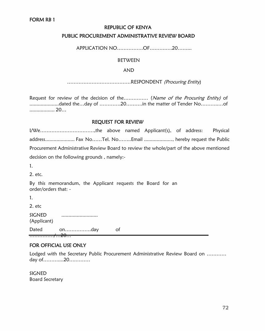
72
FORM RB 1
REPUBLIC OF KENYA
PUBLIC PROCUREMENT ADMINISTRATIVE REVIEW BOARD
APPLICATION NO…………….OF……….….20……...
BETWEEN
AND
…………………………………RESPONDENT (Procuring Entity)
Request for review of the decision of the…………… (Name of the Procuring Entity) of
.....................dated the…day of ………….20……….in the matter of Tender No………..…of
.................. 20…
REQUEST FOR REVIEW
I/We……………………………,the above named Applicant(s), of address: Physical
address..................... Fax No……Tel. No……..Email ...................., hereby request the Public
Procurement Administrative Review Board to review the whole/part of the above mentioned
decision on the following grounds , namely:-
1.
2. etc.
By this memorandum, the Applicant requests the Board for an
order/orders that: -
1.
2. etc
SIGNED ..........................
(Applicant)
Dated on…………….day of
……………/…20…
FOR OFFICIAL USE ONLY
Lodged with the Secretary Public Procurement Administrative Review Board on …………
day of………....20….………
SIGNED
Board Secretary

73