Embed Size (px)
Citation preview
Water Supply Code of Australia Melbourne Retail Water Agencies Edition
Version 2.0
WATER SERVICES A SSOCIATIONOF AUSTR ALIA
WSA 03–2011-3.1
TM
City West Water
MRWA EDITION – VERSION 2.0 APRIL 2012
Water Supply Code of Australia
WSA 03—2011-3.1
Melbourne Retail Water Agencies Edition (Including City West Water, South East Water & Yarra Valley Water)
Version 2.0
Previous edition WSA 03: 2002-2.3

WSA 03—2011-3.1
MRWA EDITION – VERSION 2.0 APRIL 2012
CONTENTS
PREFACE 6
INTRODUCTION 9
PART 0: GLOSSARY OF TERMS AND ABBREVIATIONS
I Glossary of Terms 12
II Abbreviations 29
III Referenced Documents 33
PART 1: PLANNING AND DESIGN
Contents 38
1 General 51
2 System Planning 58
3 Hydraulic Design 79
4 Products and Materials 89
5 General Design 101
6 System Pressure Management 128
7 Structural Design 151
8 Appurtenances 165
9 Design Review and Drawings 194
PART 2: CONSTRUCTION
Contents 200
10 General 206
11 General Construction 208
12 Products and Materials 219
13 Excavation 224
14 Bedding for Pipes 229
15 Pipe Laying, Jointing and Connecting 230
16 Pipe Embedment and Support 249
17 Fill 251
18 Swabbing 254
19 Acceptance Testing 256
20 Disinfection 263
21 Tolerances on As-Constructed Work 264
22 Connections to Existing Water Mains 266
23 Restoration 270
24 Work As Constructed Details 272
MRWA EDITION – VERSION 2.0 COPYRIGHT APRIL 2012
Water Supply Code of Australia
WSA 03—2011-3.1
Melbourne Retail Water Agencies Edition
(Including City West Water, South East Water & Yarra Valley Water)
Version 2.0
Part 1: Planning and Design
WSA 03—2011-3.1
MRWA EDITION – VERSION 2.0 COPYRIGHT APRIL 2012
CONTENTS
1 GENERAL
1.1 SCOPE
1.2 PLANNING AND DESIGN 1.2.1 Objectives 1.2.2 Scope and requirements 1.2.3 Concept plan format 1.2.4 Critical infrastructure protection
1.2.4.1 Asset categorisation 1.2.4.2 All hazards – Infrastructure protection
1.2.5 Detailed design 1.2.5.1 Designer’s needs and responsibilities 1.2.5.2 Requirements to be addressed 1.2.5.3 Design outputs
1.2.6 Design life 1.2.7 Instrumentation and control systems
1.3 CONSULTATION WITH OTHER PARTIES
2 SYSTEM PLANNING
2.1 GENERAL
2.2 SYSTEM PLANNING PROCESS 2.2.1 General 2.2.2 Extending / upgrading an existing water supply system 2.2.3 Providing a new water supply 2.2.4 Non-drinking water as drinking water substitution
2.3 DEMANDS 2.3.1 General 2.3.2 Dual water supply systems
2.3.2.1 General 2.3.2.2 Rainwater tanks
2.3.3 Demand assessment 2.3.3.1 General 2.3.3.2 Residential 2.3.3.3 Non-residential
2.3.4 Peak demands 2.3.4.1 General 2.3.4.2 Peak day demand 2.3.4.3 Peak hour demand
2.4 SYSTEM CONFIGURATION
2.5 SYSTEM HYDRAULICS 2.5.1 General 2.5.2 Network analysis 2.5.3 Operating pressures
2.5.3.1 Service pressure 2.5.3.2 Maximum allowable service pressure 2.5.3.3 Minimum service pressure 2.5.3.4 Average service pressure
2.5.4 Pressure variation analysis 2.5.5 Determining supply zones
2.5.5.1 General 2.5.5.2 Use of minimum allowable or desirable minimum service pressures
WSA 03—2011-3.1
MRWA EDITION – VERSION 2.0 COPYRIGHT APRIL 2012
2.5.5.3 Use of desirable minimum static pressure
2.6 WATER QUALITY 2.6.1 General 2.6.2 Prevention of back siphonage 2.6.3 Water age 2.6.4 Disinfection
2.7 SEPARATION OF DRINKING AND NON-DRINKING WATER SUPPLY SYSTEMS 2.7.1 Permanent cross links and cross connections 2.7.2 Temporary cross links
2.8 PUMPING STATIONS 2.8.1 General 2.8.2 Design factors
2.8.2.1 System related factors 2.8.2.2 Site related factors 2.8.2.3 Service related factors
2.8.3 Concept design
2.9 SERVICE RESERVOIRS 2.9.1 Storage capacity 2.9.2 Location
2.10 TRENCHLESS TECHNIQUES FOR PIPELAYING
2.11 FUTURE SYSTEM EXPANSION
2.12 SYSTEM REVIEW
3 HYDRAULIC DESIGN
3.1 SIZING 3.1.1 General 3.1.2 Minimum pipe sizes 3.1.3 Empirical sizing of reticulation mains 3.1.4 Dual water supply systems 3.1.5 Fire flows (fire fighting hydrants and fire services) 3.1.6 Sizing by analysis
3.1.6.1 General 3.1.6.2 Head losses 3.1.6.3 Hydraulic roughness values 3.1.6.4 Flow velocities
3.2 DESIGN PRESSURES 3.2.1 General 3.2.2 Gravity systems 3.2.3 Pumped systems
3.3 PRESSURE CLASS OF SYSTEM COMPONENTS 3.3.1 Pumped systems
3.4 THRUST AND ANCHOR BLOCK DESIGN
3.5 SYSTEM TEST PRESSURE
3.6 DESIGN FOR DYNAMIC STRESSES 3.6.1 General 3.6.2 Surge 3.6.3 Fatigue 3.6.4 Fatigue de-rating of plastics pipes and fittings
3.7 TEMPERATURE DE-RATING OF PLASTICS PIPES AND FITTINGS
3.8 PIPELINE COMPONENTS MINIMUM PRESSURE CLASS
WSA 03—2011-3.1
MRWA EDITION – VERSION 2.0 COPYRIGHT APRIL 2012
4 PRODUCTS AND MATERIALS
4.1 GENERAL
4.2 DIFFERENTIATION OF DRINKING AND NON-DRINKING PIPE SYSTEMS 4.2.1 Principles 4.2.2 Water supply mains – drinking water 4.2.3 Water supply mains – non-drinking water 4.2.4 Property services – drinking water 4.2.5 Property services – non-drinking water 4.2.6 Marking tapes
4.3 DUCTILE IRON PIPELINE SYSTEMS 4.3.1 Product Specifications 4.3.2 Sizes and configurations 4.3.3 Seal coating of lining 4.3.4 Sleeving 4.3.5 Screw-on flanges for DI pipes 4.3.6 Flanged joints
4.4 PVC PIPELINE SYSTEMS
4.5 PE PIPELINE SYSTEMS
4.6 STEEL PIPELINE SYSTEMS 4.6.1 Product Specifications 4.6.2 Sizes and configurations 4.6.3 Joints 4.6.4 Field welding 4.6.5 Flanged joints
4.7 GRP PIPELINE SYSTEMS
4.8 PROTECTION AGAINST DEGRADATION 4.8.1 Application 4.8.2 Protection against aggressive environments 4.8.3 Protection against damage to coatings 4.8.4 Stainless steels
4.8.4.1 Grade selection 4.8.4.2 Welding 4.8.4.3 Threaded components
4.8.5 Cathodic protection 4.8.6 Not used 4.8.7 Protection against contaminated ground 4.8.8 Bolted connections
5 GENERAL DESIGN
5.1 GENERAL REQUIREMENTS 5.1.1 Design tolerances 5.1.2 Levels 5.1.3 Water main renewals—electrical safety and earthing to water services 5.1.4 Environmental considerations
5.1.4.1 General 5.1.4.2 Urban salinity
5.2 RETICULATION DESIGN FOR WATER QUALITY 5.2.1 Layout of water mains 5.2.2 Looped mains 5.2.3 Link mains 5.2.4 Reduced size mains
5.3 WATER MAIN ACCESS
WSA 03—2011-3.1
MRWA EDITION – VERSION 2.0 COPYRIGHT APRIL 2012
5.4 LOCATION OF WATER MAINS 5.4.1 General 5.4.2 Water mains in road reserves
5.4.2.1 General 5.4.2.2 Location in footway 5.4.2.3 Location in carriageway 5.4.2.4 Location in roundabouts and bus bays
5.4.3 Location in other than dedicated public road reserves 5.4.4 Water mains in easements 5.4.5 Dual water supply systems 5.4.6 Effect on vegetation 5.4.7 Water mains near trees 5.4.8 Contaminated sites 5.4.9 Crossings
5.4.9.1 General 5.4.9.2 Requirements for encased pipe installations
5.4.10 Railway reserves 5.4.11 Crossings of creeks or drainage reserves 5.4.12 Overhead power lines and transmission towers 5.4.13 Water mains in conjunction with landscaping and/or other development 5.4.14 Water mains on curved alignments 5.4.15 Location markers 5.4.16 Marking tape and tracer wire
5.4.16.1 General 5.4.16.2 Mains 5.4.16.3 Property services
5.5 TRENCHLESS TECHNOLOGY
5.6 SHARED TRENCHING
5.7 DUPLICATE MAINS
5.8 RIDER MAINS
5.9 CONNECTION OF NEW OFF-TAKES TO EXISTING MAINS
5.10 TERMINATION POINTS 5.10.1 Permanent ends of water mains 5.10.2 Temporary ends of water mains 5.10.3 Chlorination 5.10.4 Flushing points
5.11 PROPERTY SERVICES 5.11.1 General 5.11.2 Connections to water mains 5.11.3 Services, outlets and meters
5.12 OBSTRUCTIONS AND CLEARANCES 5.12.1 General 5.12.2 Surface obstructions 5.12.3 Clearance from transmission towers 5.12.4 Clearance from structures and property boundaries 5.12.5 Underground obstructions and services
5.12.5.1 General 5.12.5.2 Clearance requirements
5.12.6 Deviation of water mains 5.12.6.1 General 5.12.6.2 Horizontal deviation of water mains 5.12.6.3 Vertical deviation of water mains 5.12.6.4 Curving of pipes to avoid obstructions
5.13 DISUSED OR REDUNDANT PIPELINES
WSA 03—2011-3.1
MRWA EDITION – VERSION 2.0 COPYRIGHT APRIL 2012
6 SYSTEM PRESSURE MANAGEMENT
6.1 GENERAL
6.2 IN-LINE PRESSURE BOOSTER PUMPING STATIONS 6.2.1 Planning criteria 6.2.2 Concept design
6.2.2.1 General 6.2.2.2 Life cycle considerations 6.2.2.3 Functionality 6.2.2.4 Due diligence requirements 6.2.2.5 Reliability 6.2.2.6 Maintainability 6.2.2.7 Materials design 6.2.2.8 Location 6.2.2.9 Site selection 6.2.2.10 Noise control 6.2.2.11 Services 6.2.2.12 Access 6.2.2.14 Landscaping 6.2.2.15 Security 6.2.2.16 Signage 6.2.2.17 Supporting systems 6.2.2.18 Health and safety
6.2.3 Commissioning plan 6.2.3.1 General 6.2.3.2 Pre-commissioning 6.2.3.3 Commissioning
6.2.4 System planning and modelling 6.2.4.1 Modelling 6.2.4.2 Minimum pressure affecting the area 6.2.4.3 Number of affected properties within the low pressure zone
6.2.5 Booster design 6.2.5.1 General 6.2.5.2 Connection to the network 6.2.5.3 Maximum flow and pressure requirements 6.2.5.4 Design for minimum pressure boost conditions 6.2.5.5 Design for minimum flow conditions 6.2.5.6 Booster configuration design 6.2.5.7 Booster set and pump selection 6.2.5.8 Booster pipework and manifold design 6.2.5.9 Booster equipment and devices 6.2.5.10 Site specific requirements
6.2.6 Booster pipework 6.2.6.1 General design parameters 6.2.6.2 Manifolds, off-takes, suction and delivery pipework 6.2.6.3 Pressure gauges and tappings
6.2.7 Pressure accumulator tank 6.2.8 Power system and supply
6.2.8.1 General 6.2.8.2 Security of supply 6.2.8.3 Primary supply 6.2.8.4 Duplicate supply 6.2.8.5 Emergency power 6.2.8.6 On-site generator 6.2.8.7 Mobile generator 6.2.8.8 Power factor correction 6.2.8.9 Lighting
WSA 03—2011-3.1
MRWA EDITION – VERSION 2.0 COPYRIGHT APRIL 2012
6.2.9 Control and telemetry system 6.2.9.1 General 6.2.9.2 Instrumentation 6.2.9.3 System requirements 6.2.9.4 Fire flow operation
6.2.10 Alarms and controls 6.2.10.1 General 6.2.10.2 Control switches – manual and emergency operation
6.2.11 Telemetry 6.2.11.1 General 6.2.11.2 Software 6.2.11.3 Communications
6.3 PRESSURE REDUCING VALVE INSTALLATIONS 6.3.1 Planning criteria 6.3.2 Design requirements
6.4 PRESSURE SUSTAINING VALVE INSTALLATIONS 6.4.1 Planning criteria 6.4.2 Design requirements
7 STRUCTURAL DESIGN
7.1 GENERAL
7.2 STRUCTURAL CONSIDERATIONS
7.3 INTERNAL FORCES
7.4 EXTERNAL FORCES 7.4.1 General 7.4.2 Pipe cover 7.4.3 Embedment zone dimensions 7.4.4 Pipe embedment 7.4.5 Buoyancy
7.5 GEOTECHNICAL CONSIDERATIONS 7.5.1 General 7.5.2 Water mains in engineered or controlled fill 7.5.3 Water mains in non-engineered fill 7.5.4 Construction of an embankment MRWA 7.5.5 Unforeseen ground conditions
7.6 CONCRETE ENCASEMENT 7.6.1 General 7.6.2 Requirements 7.6.3 Encased steel pipelines
7.6.3.1 General 7.6.3.2 Existing steel pipelines
7.7 WATER MAINS IN UNSTABLE GROUND 7.7.1 General 7.7.2 Mine subsidence areas 7.7.3 Slip areas
7.8 ABOVE-GROUND WATER MAINS
7.9 PIPELINE ANCHORAGE 7.9.1 General 7.9.2 Thrust blocks
7.9.2.1 General 7.9.2.2 Concrete thrust blocks 7.9.2.3 Use of puddle flanges to transfer thrust 7.9.2.4 Timber and recycled plastics thrust blocks
WSA 03—2011-3.1
MRWA EDITION – VERSION 2.0 COPYRIGHT APRIL 2012
7.9.3 Not used 7.9.4 Thrust and anchor blocks for dual water supply systems 7.9.5 Restrained elastomeric seal joint water mains 7.9.6 Restraint requirements for special situations
7.9.6.1 Above-ground mains with unrestrained flexible joints 7.9.6.2 Buried steel mains with welded joints 7.9.6.3 Above-ground steel mains with welded joints 7.9.6.4 Ductile iron and steel mains with flanged joints 7.9.6.5 PE mains
7.10 BULKHEADS AND TRENCHSTOPS
7.11 NOT USED
8 APPURTENANCES
8.1 VALVES—GENERAL 8.1.1 Valving design 8.1.2 Valving principles 8.1.3 Selection considerations 8.1.4 Not used 8.1.5 Not used
8.2 STOP VALVES 8.2.1 Product Specifications 8.2.2 Installation design and selection criteria
8.2.2.1 General 8.2.2.2 Gate valves 8.2.2.3 Butterfly valves
8.2.3 Stop valves for transfer/distribution mains (>DN 300) MRWA 8.2.3.1 Bypass of stop valve
8.2.4 Stop valves for reticulation mains (≤DN 300) MRWA 8.2.4.1 Stop valves spacing
8.2.5 Not used 8.2.6 Not used 8.2.7 Stop valves—location and arrangements
8.2.7.1 General 8.2.7.2 Arrangement 1 8.2.7.3 Arrangement 2 8.2.7.4 Arrangement 3 8.2.7.5 Arrangement 4 8.2.7.6 Arrangement 5 8.2.7.7 Arrangement 6 8.2.7.8 Arrangement 7
8.2.8 Stop valve special arrangements 8.2.9 Rider mains and network configurations 8.2.10 Crossing mains – interconnection MRWA 8.2.11 Stop valves for pumping stations MRWA 8.2.12 Pump station stop valve location and arrangements
8.3 CONTROL VALVES 8.3.1 Product Specifications 8.3.2 Automatic inlet control valves (AICV) 8.3.3 Pressure reducing valves (PRV) 8.3.4 Pressure relief valves (PRelV) 8.3.5 Pump control valves 8.3.6 Pressure sustaining valves (PSV)
8.4 AIR VALVES (AV) 8.4.1 Product Specifications
WSA 03—2011-3.1
MRWA EDITION – VERSION 2.0 COPYRIGHT APRIL 2012
8.4.2 Installation design criteria 8.4.3 Air valves type 8.4.4 Air valves size 8.4.5 Air valves location 8.4.6 Use of hydrants as an alternative to air valves 8.4.7 Water sampling via air valves
8.5 NON-RETURN VALVES 8.5.1 Product Specifications 8.5.2 Installation design criteria 8.5.3 Non-return valves for pumping stations
8.6 SCOURS AND PUMP-OUT BRANCHES 8.6.1 Location and arrangements 8.6.2 Design 8.6.3 Scour application 8.6.4 Scour size 8.6.5 Scour location
8.7 SWABBING POINTS
8.8 HYDRANTS 8.8.1 Product Specifications 8.8.2 Purposes 8.8.3 Hydrant operation principles 8.8.4 Hydrant types 8.8.5 Not used 8.8.6 Hydrant outlet connections 8.8.7 Hydrant size 8.8.8 Hydrant spacing 8.8.9 Hydrant location 8.8.10 Not used 8.8.11 Hydrants at ends of mains
8.9 DISINFECTION FACILITIES 8.9.1 General 8.9.2 Reticulation mains 8.9.3 Transfer and distribution mains 8.9.4 Discharge
8.10 SURFACE FITTINGS AND MARKINGS 8.10.1 Product Specifications 8.10.2 General 8.10.3 Marking of surface fittings 8.10.4 Not used
8.11 APPURTENANCE LOCATION MARKING 8.11.1 General 8.11.2 Marker posts and plates 8.11.3 Pavement markers 8.11.4 Kerb markings
WSA 03—2011-3.1
MRWA EDITION – VERSION 2.0 COPYRIGHT APRIL 2012
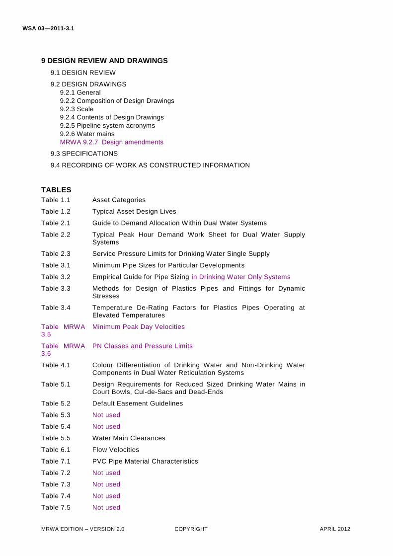
9 DESIGN REVIEW AND DRAWINGS
9.1 DESIGN REVIEW
9.2 DESIGN DRAWINGS 9.2.1 General 9.2.2 Composition of Design Drawings 9.2.3 Scale 9.2.4 Contents of Design Drawings 9.2.5 Pipeline system acronyms 9.2.6 Water mains MRWA 9.2.7 Design amendments
9.3 SPECIFICATIONS
9.4 RECORDING OF WORK AS CONSTRUCTED INFORMATION
TABLES
Table 1.1 Asset Categories
Table 1.2 Typical Asset Design Lives
Table 2.1 Guide to Demand Allocation Within Dual Water Systems
Table 2.2 Typical Peak Hour Demand Work Sheet for Dual Water Supply Systems
Table 2.3 Service Pressure Limits for Drinking Water Single Supply
Table 3.1 Minimum Pipe Sizes for Particular Developments
Table 3.2 Empirical Guide for Pipe Sizing in Drinking Water Only Systems
Table 3.3 Methods for Design of Plastics Pipes and Fittings for Dynamic Stresses
Table 3.4 Temperature De-Rating Factors for Plastics Pipes Operating at Elevated Temperatures
Table MRWA 3.5
Minimum Peak Day Velocities
Table MRWA 3.6
PN Classes and Pressure Limits
Table 4.1 Colour Differentiation of Drinking Water and Non-Drinking Water Components in Dual Water Reticulation Systems
Table 5.1 Design Requirements for Reduced Sized Drinking Water Mains in Court Bowls, Cul-de-Sacs and Dead-Ends
Table 5.2 Default Easement Guidelines
Table 5.3 Not used
Table 5.4 Not used
Table 5.5 Water Main Clearances
Table 6.1 Flow Velocities
Table 7.1 PVC Pipe Material Characteristics
Table 7.2 Not used
Table 7.3 Not used
Table 7.4 Not used
Table 7.5 Not used
WSA 03—2011-3.1
MRWA EDITION – VERSION 2.0 COPYRIGHT APRIL 2012
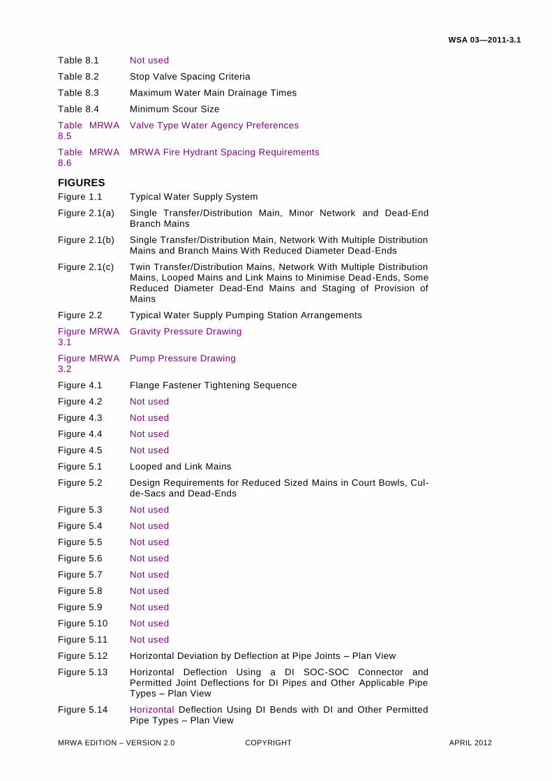
Table 8.1 Not used
Table 8.2 Stop Valve Spacing Criteria
Table 8.3 Maximum Water Main Drainage Times
Table 8.4 Minimum Scour Size
Table MRWA 8.5
Valve Type Water Agency Preferences
Table MRWA 8.6
MRWA Fire Hydrant Spacing Requirements
FIGURES
Figure 1.1 Typical Water Supply System
Figure 2.1(a) Single Transfer/Distribution Main, Minor Network and Dead-End Branch Mains
Figure 2.1(b) Single Transfer/Distribution Main, Network With Multiple Distribution Mains and Branch Mains With Reduced Diameter Dead-Ends
Figure 2.1(c) Twin Transfer/Distribution Mains, Network With Multiple Distribution Mains, Looped Mains and Link Mains to Minimise Dead-Ends, Some Reduced Diameter Dead-End Mains and Staging of Provision of Mains
Figure 2.2 Typical Water Supply Pumping Station Arrangements
Figure MRWA 3.1
Gravity Pressure Drawing
Figure MRWA 3.2
Pump Pressure Drawing
Figure 4.1 Flange Fastener Tightening Sequence
Figure 4.2 Not used
Figure 4.3 Not used
Figure 4.4 Not used
Figure 4.5 Not used
Figure 5.1 Looped and Link Mains
Figure 5.2 Design Requirements for Reduced Sized Mains in Court Bowls, Cul-de-Sacs and Dead-Ends
Figure 5.3 Not used
Figure 5.4 Not used
Figure 5.5 Not used
Figure 5.6 Not used
Figure 5.7 Not used
Figure 5.8 Not used
Figure 5.9 Not used
Figure 5.10 Not used
Figure 5.11 Not used
Figure 5.12 Horizontal Deviation by Deflection at Pipe Joints – Plan View
Figure 5.13 Horizontal Deflection Using a DI SOC-SOC Connector and Permitted Joint Deflections for DI Pipes and Other Applicable Pipe Types – Plan View
Figure 5.14 Horizontal Deflection Using DI Bends with DI and Other Permitted Pipe Types – Plan View
WSA 03—2011-3.1
MRWA EDITION – VERSION 2.0 COPYRIGHT APRIL 2012
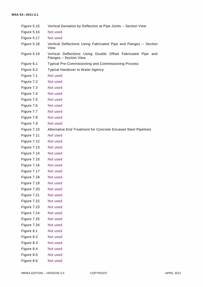
Figure 5.15 Vertical Deviation by Deflection at Pipe Joints – Section View
Figure 5.16 Not used
Figure 5.17 Not used
Figure 5.18 Vertical Deflections Using Fabricated Pipe and Flanges – Section View
Figure 5.19 Vertical Deflections Using Double Offset Fabricated Pipe and Flanges – Section View
Figure 6.1 Typical Pre-Commissioning and Commissioning Process
Figure 6.2 Typical Handover to Water Agency
Figure 7.1 Not used
Figure 7.2 Not used
Figure 7.3 Not used
Figure 7.4 Not used
Figure 7.5 Not used
Figure 7.6 Not used
Figure 7.7 Not used
Figure 7.8 Not used
Figure 7.9 Not used
Figure 7.10 Alternative End Treatment for Concrete Encased Steel Pipelines
Figure 7.11 Not used
Figure 7.12 Not used
Figure 7.13 Not used
Figure 7.14 Not used
Figure 7.15 Not used
Figure 7.16 Not used
Figure 7.17 Not used
Figure 7.18 Not used
Figure 7.19 Not used
Figure 7.20 Not used
Figure 7.21 Not used
Figure 7.22 Not used
Figure 7.23 Not used
Figure 7.24 Not used
Figure 7.25 Not used
Figure 7.26 Not used
Figure 8.1 Not used
Figure 8.2 Not used
Figure 8.3 Not used
Figure 8.4 Not used
Figure 8.5 Not used
Figure 8.6 Not used
WSA 03—2011-3.1
MRWA EDITION – VERSION 2.0 COPYRIGHT APRIL 2012
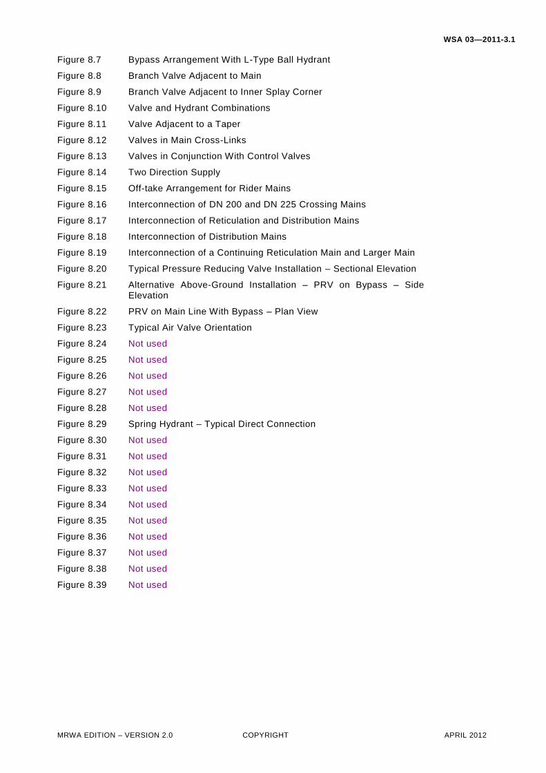
Figure 8.7 Bypass Arrangement With L-Type Ball Hydrant
Figure 8.8 Branch Valve Adjacent to Main
Figure 8.9 Branch Valve Adjacent to Inner Splay Corner
Figure 8.10 Valve and Hydrant Combinations
Figure 8.11 Valve Adjacent to a Taper
Figure 8.12 Valves in Main Cross-Links
Figure 8.13 Valves in Conjunction With Control Valves
Figure 8.14 Two Direction Supply
Figure 8.15 Off-take Arrangement for Rider Mains
Figure 8.16 Interconnection of DN 200 and DN 225 Crossing Mains
Figure 8.17 Interconnection of Reticulation and Distribution Mains
Figure 8.18 Interconnection of Distribution Mains
Figure 8.19 Interconnection of a Continuing Reticulation Main and Larger Main
Figure 8.20 Typical Pressure Reducing Valve Installation – Sectional Elevation
Figure 8.21 Alternative Above-Ground Installation – PRV on Bypass – Side Elevation
Figure 8.22 PRV on Main Line With Bypass – Plan View
Figure 8.23 Typical Air Valve Orientation
Figure 8.24 Not used
Figure 8.25 Not used
Figure 8.26 Not used
Figure 8.27 Not used
Figure 8.28 Not used
Figure 8.29 Spring Hydrant – Typical Direct Connection
Figure 8.30 Not used
Figure 8.31 Not used
Figure 8.32 Not used
Figure 8.33 Not used
Figure 8.34 Not used
Figure 8.35 Not used
Figure 8.36 Not used
Figure 8.37 Not used
Figure 8.38 Not used
Figure 8.39 Not used
MRWA EDITION – VERSION 2.0 COPYRIGHT APRIL 2012
Water Supply Code of Australia
WSA 03—2011-3.1
Melbourne Retail Water Agencies Edition
(Including City West Water, South East Water & Yarra Valley Water)
Version 2.0
Part 2: Construction
Third Edition
Version 3.1
WSA 03—2011-3.1
MRWA EDITION – VERSION 2.0 COPYRIGHT APRIL 2012
CONTENTS
10 GENERAL 10.1 SCOPE 10.2 INTERPRETATION
11 GENERAL CONSTRUCTION 11.1 GENERAL 11.2 ORDER OF CONSTRUCTION, TESTING AND COMMISSIONING 11.3 CONTRACT INTERFACES 11.4 CUSTOMER FOCUS
11.4.1 General 11.4.2 Resolution of complaints MRWA 11.4.3 Legislative compliance
11.5 PROTECTION OF PROPERTY AND ENVIRONMENT 11.5.1 Protection of other services 11.5.2 Disused / Redundant water mains 11.5.3 Road reserves or other thoroughfares
11.5.3.1 Road opening permits 11.5.3.2 Treatment of pavements and other surfaces 11.5.3.3 Cleanliness of roads, paths, accesses and drainage paths
11.5.3.4 Storage of products, materials and equipment 11.5.3.5 Obstruction of street drainage
11.5.4 Private and public properties 11.5.5 Protection of the environment and heritage areas
11.5.5.1 General 11.5.5.2 Collection and disposal of wastes 11.5.5.3 Protection of adjacent lands and vegetation 11.5.5.4 Control of water pollution 11.5.5.5 Contaminated soils 11.5.5.6 Fire ant areas 11.5.5.7 Control of noise and atmospheric pollution 11.5.5.8 Equipment and machinery use in bush fire prone areas
MRWA 11.5.5.9 Work within high risk fire areas 11.6 OPERATION OF WATER SUPPLY NETWORK 11.7 ALTERATION OF EXISTING SERVICES 11.8 CONNECTION TO AND WORK ON EXISTING ASBESTOS WATER MAINS 11.9 UNDER PRESSURE CUT-IN CONNECTION EQUIPMENT 11.10 SURVEY MARKS 11.11 NOT USED 11.12 LATENT CONDITIONS
12 PRODUCTS AND MATERIALS 12.1 AUTHORISED PRODUCTS AND MATERIALS
12.1.1 General 12.2 DELIVERY INSPECTION OF PRODUCTS AND MATERIALS 12.3 TRANSPORTATION, HANDLING AND STORAGE OF PRODUCTS AND MATERIALS
12.3.1 General 12.3.2 Transportation 12.3.3 Unloading and handling 12.3.4 On-site storage MRWA 12.3.5 Coiled PE pipe
12.4 REJECTED PRODUCTS AND MATERIALS 12.5 CONCRETE WORKS 12.6 SUPPLY OF WATER TO THE WORKS 12.7 SUPPLY OF WATER TO EXISTING PROPERTIES 12.8 UNDER PRESSURE CUT-IN CONNECTION TO PRESSURE PIPES DN 80
WSA 03—2011-3.1
MRWA EDITION – VERSION 2.0 COPYRIGHT APRIL 2012
12.8.1 Flanged off-takes 12.8.2 Valves 12.8.3 Flange holes 12.8.4 Gaskets 12.8.5 Bolting system
12.8.5.1 General 12.8.5.2 Carbon or alloy steel bolt assemblies 12.8.5.3 Stainless steel bolt assemblies
12.8.6 Insulation sleeves 12.8.7 Plastics inserts for metallic pipes
13 EXCAVATION 13.1 PRECAUTIONS 13.2 LIMITS OF CLEARING AND EXCAVATION 13.3 PROTECTION OF TREES
13.3.1 General precautions 13.3.2 Protection of roots
13.4 BLASTING 13.5 SUPPORT OF EXCAVATIONS 13.6 DRAINAGE AND DEWATERING 13.7 UNDER PRESSURE CUT-IN CONNECTION TO PRESSURE PIPES ≥DN 80
13.7.1 Excavation requirements 13.7.2 Extent of excavation
13.8 EXCAVATION ACROSS IMPROVED SURFACES 13.9 TRENCH EXCAVATION
13.9.1 General 13.9.2 Construction of embankment 13.9.3 Clearances for on-site works
13.10 REFILL OF EXCESSIVE EXCAVATION 13.11 FOUNDATIONS AND FOUNDATION STABILISATION 13.12 SURPLUS EXCAVATED MATERIAL 13.13 TRENCHLESS EXCAVATION
14 BEDDING FOR PIPES 14.1 TRENCH FLOOR PREPARATION 14.2 BEDDING AND PIPE SUPPORT 14.3 SPECIAL PIPE SUPPORT FOR NON-SUPPORTIVE SOILS
15 PIPE LAYING, JOINTING AND CONNECTING 15.1 INSTALLATION OF PIPES
15.1.1 General 15.1.2 Dual water supply areas 15.1.3 Cleaning, inspection and joint preparation 15.1.4 Laying 15.1.5 Mains renewals
15.2 HORIZONTAL AND VERTICAL DEFLECTIONS OF PIPES 15.2.1 General 15.2.2 Deflection at a pipe joint 15.2.3 Curving of PE pipe
15.3 HORIZONTAL AND VERTICAL SEPARATION OF CROSSING PIPELINES 15.4 VALVES, HYDRANTS AND OTHER APPURTENANCES 15.5 UNDER PRESSURE CUT-IN CONNECTION TO PRESSURE PIPES DN 80
15.5.1 Inspection of host pipe 15.5.2 Inspection of valve to be installed 15.5.3 Disinfection of fittings and equipment 15.5.4 Installation of flanged off-take clamp (non steel mains)
MRWA 15.5.4.1 Installation of flanges to steel mains 15.5.5 Installation of the valve
WSA 03—2011-3.1
MRWA EDITION – VERSION 2.0 COPYRIGHT APRIL 2012
15.5.6 Equipment operation and cut-in operation 15.5.7 Recording and reporting
15.6 FLOTATION CONTROL 15.7 THRUST, ANCHOR BLOCKS AND RESTRAINED JOINTS 15.8 TAPPING OF MAINS, PROPERTY SERVICES AND WATER METERS 15.9 TRENCH STOPS 15.10 BULKHEADS 15.11 CORROSION PROTECTION OF DUCTILE IRON 15.12 MARKING TAPES
15.12.1 Not used 15.12.2 Detectable marking tape 15.12.3 Tracer wire MRWA 15.12.4 Property services
15.13 VALVES, HYDRANTS AND SURFACE BOXES AND FITTINGS 15.13.1 Installation 15.13.2 Valve chambers for large diameter mains
15.14 SCOURS 15.15 BORED PIPES UNDER ROADS, DRIVEWAYS AND ELSEWHERE
MRWA 15.15.1 Grouting of the annulus 15.16 AQUEDUCTS 15.17 BRIDGE CROSSINGS 15.18 APPURTENANCE LOCATION MARKING 15.19 FLANGED JOINTS 15.20 WELDING OF STEEL PIPELINES
15.20.1 General MRWA 15.20.1.1 Steel pipeline welder qualification MRWA 15.20.1.2 Weld quality assurance and testing
15.20.2 Field welding of flanges 15.20.3 Reinstatement of cement mortar lining 15.20.4 Reinstatement using a tape system
15.20.4.1 Surface preparation 15.20.4.2 Priming surfaces 15.20.4.3 Mastic filler 15.20.4.4 Tape application MRWA 15.20.4.5 Overwrap application
15.20.5 Reinstatement of external corrosion protection at joints using a heat-shrinkable sleeve system
15.20.5.1 Surface preparation 15.20.5.2 Preheat pipe 15.20.5.3 Priming of surfaces 15.20.5.4 Mastic filler 15.20.5.5 Heat-shrinkable sleeve preparation 15.20.5.6 Heat-shrinkable sleeve application
MRWA 15.20.6 Coating testing MRWA 15.20.7 Ultra High Build Epoxy Repairs MRWA 15.20.8 Corrosion protection MRWA 15.20.9 Cathodic protection MRWA 15.20.10 Fabricated steel fittings
15.21 WELDING OF PE PIPELINES MRWA 15.21.1 General MRWA 15.21.2 Butt welding MRWA 15.21.3 Electrofusion welding MRWA 15.21.4 Extrusion welding
16 PIPE EMBEDMENT AND SUPPORT 16.1 GENERAL 16.2 EMBEDMENT MATERIALS 16.3 COMPACTION OF EMBEDMENT
WSA 03—2011-3.1
MRWA EDITION – VERSION 2.0 COPYRIGHT APRIL 2012
16.3.1 Methods 16.4 SPECIAL BEDDING AND EMBEDMENTS / GEOTEXTILE SURROUND AND PILLOW 16.5 REMOVAL OF TRENCH SUPPORTS 16.6 CONCRETE EMBEDMENT AND ENCASEMENT
17 FILL 17.1 TRENCH FILL (BACKFILL)
17.1.1 Material requirements 17.1.1.1 Trafficable Areas 17.1.1.2 Non-Trafficable Areas
17.1.2 Placement 17.1.3 Compaction of trench fill
17.2 EMBANKMENT FILL 17.3 TRENCHLESS EXCAVATION FILL
18 SWABBING 18.1 GENERAL 18.2 SWABS 18.3 SWABBING AND FLUSHING PROCEDURE
19 ACCEPTANCE TESTING 19.1 GENERAL 19.2 VISUAL INSPECTION 19.3 COMPACTION TESTING
19.3.1 General 19.3.2 Compaction testing requirements
19.3.2.1 General 19.3.2.2 Not used 19.3.2.3 Not used 19.3.2.4 Not used 19.3.2.5 Retesting
19.4 HYDROSTATIC PRESSURE TESTING 19.4.1 General
MRWA 19.4.1.1 PE pipeline testing MRWA 19.4.1.2 Test equipment
19.4.2 Mains 19.4.3 Property services 19.4.4 Under pressure cut-in connections
19.5 BLOCK TESTING DUAL WATER SUPPLY SYSTEMS FOR CONNECTIVITY 19.6 INSULATED JOINT RESISTANCE TEST 19.7 WATER QUALITY TESTING
19.7.1 General 19.7.2 Test procedure 19.7.3 Satisfactory water quality test 19.7.4 Failure of test
20 DISINFECTION 20.1 APPLICATION 20.2 FLUSHING OF DISINFECTION WATER
21 TOLERANCES ON AS-CONSTRUCTED WORK 21.1 GENERAL 21.2 HORIZONTAL TOLERANCES
21.2.1 Water mains and in-line structures 21.2.2 Property services and meters
21.3 VERTICAL TOLERANCES 21.3.1 Water mains, property connections and structures 21.3.2 Verticality (“plumb”)
21.4 TOLERANCES ON FINISHED SURFACE STRUCTURES AND FITTINGS
WSA 03—2011-3.1
MRWA EDITION – VERSION 2.0 COPYRIGHT APRIL 2012
21.5 CAST IN-SITU CONCRETE STRUCTURES AND SLABS
22 CONNECTIONS TO EXISTING WATER MAINS 22.1 GENERAL 22.2 UNDER PRESSURE CONNECTIONS 22.3 INSERTED TEE CONNECTIONS
22.3.1 Shutdown of existing water mains 22.3.2 Making the connection to existing water main 22.3.3 Re-charging the shutdown water main
22.4 NOT USED 22.5 RECONNECTION OF PROPERTIES SUPPLIED BY TEMPORARY PRIVATE SERVICES
23 RESTORATION 23.1 GENERAL 23.2 PAVEMENTS 23.3 LAWNS 23.4 GRASSED AREAS 23.5 BUSHLAND 23.6 PROVISION FOR AND RECTIFICATION OF SETTLEMENT 23.7 MAINTENANCE OF RESTORED SURFACES
24 WORK AS CONSTRUCTED DETAILS
TABLES
Table 18.1 Not used
Table 19.1 Minimum Compaction of Embedment, Trench Fill and Embankments
Table MRWA 19.2
Hydrostatic Pressure Testing
FIGURES
Figure 13.1 Not used
Figure 15.1 Not used
Figure 15.2 Not used
Figure 15.3 Not used
Figure 15.4 Not used