Embed Size (px)
Citation preview

Water Supply Facilities Maintenance Manual
2006
Chapter 9.Treated Water Transmission and Distribution Facilities
Chapter 10. Water Service Fittings
(The Excerpt)
Ministry of Health, Labour and Welfare

Chapter 9. Treated Water Transmission and Distribution Facilities
Chapter 10. Water Service Fittings
(The Excerpt)
This manual consists of extracts from Chapter 9. Treated Water Transmission and Distribution Facilities,
and Chapter 10. Water Service Fittings of “Water Supply Facilities Maintenance Manual 2006 [Japan Water
Works Association]”
The numbering of Figures and Tables in the extracts is identical to that in the original manual.


【Table of contents】
9. Treated Water Transmission and Distribution Facilities ................................... 1
9.1. General ........................................................................................................ 1
9.1.1. Basic Items ..............................................................................................................................1
9.1.2. Rational Management .............................................................................................................3
9.1.3. Evaluation and diagnosis of the function ................................................................................4
9.1.4. Management of Operation ......................................................................................................7
9.1.5. Upkeep and Replacement .......................................................................................................8
9.1.6. Risk Management ...................................................................................................................9
9.1.7. Prevention of Water Leakage ................................................................................................ 10
9.1.8. Management of Information ................................................................................................. 11
9.2. Operation of Treated Water Transmission and Distribution System ......... 11
9.2.1. General .................................................................................................................................. 11
9.2.2. Rational Water Management of Treated Water Transmission and Distribution .................... 11
9.2.3. Management of Treated Water Transmission and Distribution Facilities Operation ............ 17
9.2.4. Water Distribution Control ................................................................................................... 19
9.3. Service Reservoir, Standpipe, Elevated Tank and Regulating Reservoir . 23
9.3.1. General .................................................................................................................................. 23
9.3.2. Service Reservoir .................................................................................................................. 24
9.3.3. Standpipe and Elevated Tank ................................................................................................ 31
9.3.4. Regulation reservoir (Annotation is omitted.) ...................................................................... 32
9.4. Treated Water Transmission Pumping Station, Distribution Pumping Station and Booster Pumping Station .............................................................. 32
9.4.1. General .................................................................................................................................. 32
9.4.2. Treated Water Transmission Pumping Station ...................................................................... 32
9.4.3. Water Distribution Pumping Station ..................................................................................... 41
9.4.4. Booster pumping station ....................................................................................................... 42
9.5. Treated Water Transmission Mains and Water Distribution Mains .......... 42
9.5.1. General .................................................................................................................................. 42
9.5.2. Understanding of Information on Water mains ..................................................................... 43
9.5.3. Management of drawings etc. ............................................................................................... 44
9.5.4. Diagnosis and evaluation of water mains ............................................................................. 44
9.5.5. Replacement Plan of Water Mains ........................................................................................ 50
9.5.6. Cleaning and Disinfection of Water Mains and Removal of Impurities ............................... 54
9.5.7. Prevention and Restoration of Accidents on Water Mains .................................................... 61
9.5.8. Leakage prevention ............................................................................................................... 70
9.5.9. Water mains Bridge and Bridge-piggybacked Water Mains ................................................. 81
9.5.10. Seabed treated water transmission mains (Annotation is omitted) ..................................... 83
9.5.11. Pipe laying in the multipurpose underground utility conduit (Annotation is omitted) ....... 83
9.5.12. Treated water transmission conduit (Annotation is omitted) .............................................. 83
9.6. Facilities as measures against an earthquake (Annotation is omitted) ..... 83
9.6.1. General (Annotation is omitted) ........................................................................................... 83
9.6.2. Water tank as measures against an earthquake (Annotation is omitted) ............................... 83
9.6.3. Large capacity treated water transmission mains (Annotation is omitted) ........................... 83
9.6.4. Interconnection water mains as measures against an earthquake (Annotation is omitted) ... 84
9.7. Ancillary Facilities .................................................................................... 84
9.7.1. General .................................................................................................................................. 84
9.7.2. Valves .................................................................................................................................... 84
9.7.3. Air valves .............................................................................................................................. 84
9.7.4. Hydrants ................................................................................................................................ 84
9.7.5. Reducing Vales ..................................................................................................................... 85
9.7.6. Emergency cut-off valves ..................................................................................................... 85
9.7.7. Flow meters and water pressure gauges................................................................................ 85
9.7.8. Drainage facilities ................................................................................................................. 85
9.7.9. Manholes............................................................................................................................... 85
9.7.10. Automatic water quality analyzers ...................................................................................... 86
9.7.11. Cathodic Protection Facilities ............................................................................................. 86
9.7.12. Telemetry Facilities ............................................................................................................. 86
9.7.13. Items of consideration to cold regions (Annotation is omitted) .......................................... 86
9.8. Information Management .......................................................................... 86
9.8.1. General .................................................................................................................................. 86
9.8.2. Management of Drawings ..................................................................................................... 87
9.8.3. Management of registers ....................................................................................................... 89
9.8.4. Preparation of permission documents (Annotation is omitted. ............................................. 90
9.8.5. Mapping System ................................................................................................................... 90
9.8.6. Road management system (Annotation is omitted.) ............................................................. 93
10. Water Service Fittings ................................................................................... 94
10.1. General .................................................................................................... 94
10.1.1. Basic Items .......................................................................................................................... 94
10.1.2. Operation and Maintenance of Water Service Fittings ....................................................... 97
10.1.3. Public Relations and Public Hearing in Regard to Maintenance of Water Service
Fittings .......................................................................................................................................... 100
10.2. Method of Water Service ....................................................................... 101
10.2.1. General .............................................................................................................................. 101
10.2.2. Direct Pressure Type ......................................................................................................... 102
10.2.3. Receiving Cistern Type ..................................................................................................... 103

10.2.4. Legislative provisions for hygienic management of storage tank type water supply
(Annotation is omitted.) ................................................................................................................ 106
10.2.5. Ownership and demarcation for management .................................................................. 106
10.3. Hygienic Measures ................................................................................ 106
10.3.1. General .............................................................................................................................. 106
10.3.2. Securement of quality of tap water ................................................................................... 106
10.3.3. Backflow Prevention ........................................................................................................ 107
10.4. Unusual Phenomena .............................................................................. 110
10.4.1. General .............................................................................................................................. 110
10.4.2. Abnormal sound and vibration .......................................................................................... 110
10.4.3. Coloring and Odor of Tap Water ....................................................................................... 110
10.4.4. Improvement Measures..................................................................................................... 110
10.5. Causes and Measures of Accidents and their Examples ....................... 113
10.5.1. General .............................................................................................................................. 113
10.5.2. Water Pollution ................................................................................................................. 114
10.5.3. Accidents Accompanying Abnormal Phenomenon and Other Accidents ......................... 116
10.5.4. Freezing (Annotation is omitted.) ..................................................................................... 116
10.5.5. Deterioration ..................................................................................................................... 116
10.6. Installation and Construction Management of Water Service Fittings . 118
10.6.1. Types of Construction ....................................................................................................... 118
10.6.2. Reform Work .................................................................................................................... 118
10.6.3. Repair work ...................................................................................................................... 119
10.6.4. Demolition Work (Annotation is omitted.) ....................................................................... 120
10.6.5. Installation by the Designated Water Service Fittings Installer (Annotation is omitted.) . 120
10.6.6. Management of Installation of Water Service Fittings ..................................................... 120
10.6.7. Observation and Inspection .............................................................................................. 122
10.6.8. Application for exclusive occupation and excavation (Annotation is omitted.) ............... 123
10.6.9. Collection of Information on Water Mains ....................................................................... 123
10.7. Pipe laying ............................................................................................. 123
10.7.1. Items of attention related to pipe laying ........................................................................... 123
10.7.2. Prevention and Management of Risk ................................................................................ 125
10.7.3. Return and Designation of the Certificate of Chief Engineer for Installation of Water Service
Fittings (Annotation is omitted.) ................................................................................................... 125
10.7.4. Refurbishment of Water Service Fittings .......................................................................... 125
10.8. Water Service Pipe, Joints and Water Service Devices ......................... 125
10.8.1. General .............................................................................................................................. 125
10.8.2. Manner of Operation and Maintenance ............................................................................ 126
10.8.3. Water Service Pipe and Joints ........................................................................................... 126
10.8.4. Water Service Devices ...................................................................................................... 128

10.9. Water Meter ........................................................................................... 131
10.9.1. General .............................................................................................................................. 131
10.9.2. Types and Characteristics of Meters ................................................................................. 132
10.9.3. Improvement of Environment for Meter Installation ........................................................ 132
10.9.4. Maintenance of the meter ................................................................................................. 132
10.9.5. Remote Meter (Annotation is omitted.) ............................................................................ 135
10.9.6. Meter Reading System (Annotation is omitted.) .............................................................. 135
10.9.7. Incorporation of the Water Meter into JIS and Revision of the Examination Rule
(Annotation is omitted.) ................................................................................................................ 135

1
9. Treated Water Transmission and Distribution Facilities 9.1. General 9.1.1. Basic Items
1. Role of the Facilities and their Components
1) Role and matters for attention
Treated water transmission and distribution facilities are facilities to convey clean water, treated at a water treatment plant, to required locations in necessary quantity and pressure without deterioration in quality. They are mostly composed of water mains, and it is difficult to observe them by naked eyes since they are buried in the ground.
Therefore, the quality of operation and maintenance of the facilities largely affects the management of the water utility and water service.
2) Components and functions of the facilities
Treated water transmission and distribution facilities consist of service reservoirs, standpipes, elevated reservoirs, pumps, treated water transmission mains, distribution trunk mains, distribution submains, valves, and other ancillary facilities. There are three types of water transmission and distribution in accordance with the topography of the service area: (1) the gravity flow type, (2) the pumping type, and (3) their combination.
The service reservoir has a storage function to regulate the hourly changes in the distribution flow, and another storage function to provide prerequisite water volume and pressure for certain period of time even in case an accident occurs at the upstream side of the service reservoir. In the case of the gravity flow type, it is required for the system to secure the prerequisite water volume and pressure by means of the water level and the storage of the service reservoir itself.
The water main is formed with pipes and valves, a pressurized pipe conduit to secure the safety of served water, and classified into the treated water transmission main, the trunk distribution main and the distribution submain. The treated water transmission main is the water main to convey treated water from a water treatment plant to a service reservoir. The trunk distribution main is the water main to convey and distribute treated water to distribution submains. The submain is the water main from which service pipes branch to serve treated water to consumers.
As water mains, ductile iron pipe, steel pipe, stainless steel pipe, hard PVC pipe, polyethylene pipe for water supply etc. are used.
2. Operation of the facilities
1) Basics of operation
Treated water transmission and distribution facilities are operated in accordance with the demand for safe water aiming at conveying and distributing reliably and efficiently. Besides, it is important for the water to be served to consumers without failure as much as possible even at an accident, drought, disaster etc. and served as fairly as possible even in case available water volume is short. Sufficient examination shall be practiced when operating the facilities since they must unavoidably be buried under roads, and such structures as the service reservoir are not always laid out ideally according to the demand or the topography.
2) Water management and water distribution control
The operation of treated water transmission and distribution facilities is categorized into water management, which covers the entire water supply system, and water distribution control, which is undertaken for the water distribution facilities.

2
(1) Water management
It is the most important for water management to be implemented with the highest efficiency for the water supply system as a whole in consideration of the capacity of raw water intake, water storage, raw water transmission, water treatment facilities and so forth.
In case there are more than two water sources, the provision of mutual connection between facilities with each water source at respective levels of raw water transmission, water treatment, treated water transmission and distribution facilities will enable water management in accordance with condition of the flow of water sources and situation of water storage.
As to water management at the levels of the treated water transmission mains and trunk distribution mains, matters to be considered are efficient use of raw water, the minimization of total necessary costs of energy, chemicals etc. to be used, the equalization of water pressure, the control of formation of such disinfection byproducts as trihalomethanes etc., the reduction in residual chlorine and so forth.
(2) Control of water distribution
The control of water distribution shall be conducted in consideration of properties of the water distribution system itself, components of independent distribution network blocks, and correlation between the blocks. For the control of water distribution, facilities shall be operated employing such means suited to the occasion as pumping to meet the demand, and the regulation of valve aperture so that proper water pressure and allocation of water volume at normal times shall be secured, and that the impartiality shall be secured at the time of restricted water service.
Consideration shall be practiced to the maintenance of residual chlorine and the improvement in effective water ratio. In addition, it is also important to clean water mains and drain water from them to maintain water quality in them.
3) System of water management
The water utility needs to provide a system of water management to improve the level of provision of water transmission and distribution facilities and smoothly control the facilities in accordance with changing conditions aiming at insuring the level of water service so as to satisfy consumers.
3. Management of facilities
The following items shall be taken into consideration when managing water transmission and distribution facilities.
1) Prevention of pollution and maintenance of water quality
For treated water transmission and distribution facilities, efforts shall be made to prevent pollution and avoid deterioration in water quality so that the quality of treated water is maintained.
2) Prevention of water leakage
Water leakage is not only economic loss but a cause of insufficient water service and water pollution. Measures for its prevention shall be provided since water leakage also causes such collateral accidents as the cave-in of roads, traffic accidents due to frozen pavement in winter etc.
3) Measures against accidents and disasters
Provision of a plan for temporary measures etc. against accidents, disasters, terrorism and so on is indispensable. Especially, regarding the system for emergency water service and temporary restoration, an adequate cooperation system needs to be established not only within the water utility but also with such related bodies as the administrator of roads, the police etc. What is more, it is important to enter
3
into an agreement with other water utilities for support at the time of a disaster.
4) Information management
Information related to treated water transmission and distribution facilities constitutes an important matter for judgment for operation and maintenance of facilities. Successful performance of treated water transmission and distribution facilities will depend on the strategy how information is managed. As such, the method of information management, which enables precise and speedy processing and is able to provide reliable storage and easy utilization, is required.
Computerized information management systems have been broadly in use, and mapping systems and filing systems have also been introduced in the field of treated water transmission and distribution facilities as well.
5) Conservation and facility operation
Inspection and maintenance of facilities shall soundly be carried out at normal times for the conservation of treated water transmission and distribution facilities so that no trouble is caused in the function of respective facilities and the system as a whole. It is important for a monitoring system to be provided so as to quickly detect an accident.
Treated water transmission and distribution facilities shall be monitored and operated so that the function of respective facilities can fully be exerted so as to secure proper water volume and pressure. In addition, attention is also paid to energy conservation.
9.1.2. Rational Management
1. Introduction of rational management
As to the method of rational management, the following steps shall be taken:
The level of the aim of treated water transmission and distribution facilities is to be clearly defined.
The level of the aim shall be examined from the two facets: (i) the function to be originally endowed with
the facilities, and (ii) the measures to operate and maintain them.
The project and related work, which have been undertaken so far, shall fundamentally be reexamined
to precisely grasp the status quo where problems are and what their natures are in regard to the aim.
Measures shall be planned in accordance with the problems and the aim. The measures shall be
examined so that the method to understand the present status and the development of technologies needed
to solve the problems are included. Measures shall be studied to explain to the consumers in a way for
their easy understanding, and earn their consent.
Priorities of the measures to be implemented shall be set up and they shall steadily be carried out.
2. Aim of the operation of facilities
The items to be aimed for the operation of treated water transmission and distribution facilities are as follows:
1) Treated water transmission and distribution mains
Treated water transmission and distribution mains shall be constructed so that water service is reliably provided in proper volume and pressure at normal times, and that they can exert the minimum necessary function as a lifeline. Given this, it is important that their maintenance is easy, and measures for

4
preservation of water quality in the mains are provided.
To this end, treated water transmission mains and distribution mains need to be separated; and service areas of an appropriate size shall be formed by water mains networks.
It is needed for the water mains network to embody a system which can collect information, in real time, related to water pressure, volumes of water transmission and distribution, their directions, and water quality, and that which can remotely control valves etc. as needed in accordance with the information.
2) Operation of the service reservoir
In case the service reservoir possesses capacity to absorb hourly changes in the volume of water to be distributed, the burden on water treatment facilities can be reduced. The stored capacity can be utilized as an emergency source or supplemental source of water at the time of a great earthquake or drought.
However, the capacity of the service reservoir shall appropriately be determined according to the size of the service area and the condition of the water mains network since, if the capacity is too large, water will stagnate causing deterioration in water quality and an increase in such disinfection byproducts as trihalomethanes.
Besides, the capacity of the service reservoir needs to be determined in consideration of the size of the water distribution block and the capacity of existing service reservoirs.
9.1.3. Evaluation and diagnosis of the function
Information obtained through inspection, research etc. of facilities shall be exploited to always maintain the function of treated water transmission and distribution facilities in good condition, and restructure them into a system at a higher level.
Based on such information, the existing function and capacity of the facilities shall be diagnosed and evaluated as much quantitatively as possible so as to undertake proper work of replacement, repair etc.
1. Evaluation of function of treated water transmission and distribution facilities
For the evaluation of treated water transmission and distribution facilities, it is indispensable that not only the strength and durability of unit facilities are examined, but they are diagnosed and evaluated while focusing on their function as treated water transmission and distribution systems within the water supply facilities as a whole.
1) Evaluation of facilities
The roles of treated water transmission and distribution facilities are to store, transmit, distribute and serve treated water. Evaluation of facilities is carried out from the points of view whether or not the facilities can soundly exert their functions, if they are sufficiently durable and reliable with spare capacity, or if they can easily function efficiently and economically.
The evaluation standard for treated water transmission and distribution facilities needs to constitute with the following conditions:
(1) Service area
The service area is to be set so as to deal with the location and topography of the water treatment plant, the actual water demand etc. The service area shall be divided into blocks of appropriate size horizontally as well as vertically so that no disparity is brought about in terms of water pressure and quality; that the energy consumption is the minimum; and that control of water volume and pressure becomes easy.

5
(2) Functions of transmission and distribution
Water mains shall be divided into the treated water transmission main and the water distribution main in terms of function so that control of pumps and operation of service reservoirs are easy, and that excessive water pressure or extreme changes in water pressure are not caused.
Treated water transmission mains and important trunk water distribution mains shall be duplicated and fit with pipe materials and joints which are highly earthquake-resistant.
Trunk water distribution mains shall be provided with interconnection facilities with other distribution systems so that mutual utilization of water between them is possible in normal as well as abnormal times. The capacity of the distribution main shall be able to deal with the water demand from the incumbent service area and, in addition, have an allowance to meet the requirement to supply to the neighboring service areas in aid.
(3) Water service function
Water distribution submains shall form mains networks as blocks of appropriate size fit in with the topography of appropriate sizes avoiding cul-de-sac pipes etc. so as to maintain proper water volume, pressure and quality.
Furthermore, valves shall be installed on distribution mains, which interconnect neighboring blocks, so that the water flow can be stopped.
(4) Storage function
The service reservoir and the standpipe shall possess big enough capacity to deal with hourly changes in water distribution volume, and be secured with capacity which can meet demand at abnormal times. The burden to be borne by the water treatment process and the treated water transmission control will become large in case the capacity of the service reservoir is small. The reliability of water service at a time of an accident will be low with insufficient service reservoir capacity.
2) Evaluation of the function
Evaluation of the function of treated water transmission and distribution facilities is undertaken for the entire facilities focusing on the following items:
(1) Analysis of water distribution volume
One of standards to evaluate whether or not the function of treated water transmission and distribution facilities is efficiently exerted is the analysis of water distribution volume.
The target to be aimed for the effective water ratio shall be more than 98% for large scale water utilities and more than 95% for small and medium ones as prescribed in the “Visions for Water Supply”.
The effective water ratio depends on the quantity of water leakage on water mains and so forth. In case the effective water ratio is low, there may be some points in water distribution facilities at which the function is insufficient. Accordingly, the cause of such defects shall be investigated and measures for improvement shall be provided.
Reference “9.5.8 Prevention of Water Leakage” regarding the analysis of water distribution volume.
(2) Energy consumption
One of standards to evaluate whether or not the function of treated water transmission and distribution facilities is efficiently exerted is the comparison of consumption of energy in the system, personnel expenses etc.

6
When observing the changes over years in power consumption per unit water volume (consumption rate = total annual power consumption/annual served water volume) in treated water transmission and distribution facilities, in case the value has increased, its cause and measures for it shall be examined. It is also useful to compare the value with those of other water utilities of which size and form of water service are similar to the present one.
In addition, by means of comparison of the personnel costs per unit water volume in the same way, it will become possible to judge whether or not the adoption of unmanned facility operation, automation, or remote control method is feasible.
In case a plan for the improvement of facilities is determined, a plan, of which efficiency and the ease of operation and maintenance (O&M) are well balanced, shall be adopted based on the evaluation of efficient operation of facilities, the ease of handling, easiness and economic benefits of O&M and so forth.
(3) Water service
Treated water transmission and distribution facilities can also be evaluated from the point of view of water service in terms of supply of safe and palatable water, the implementation of direct pressure water service etc.
The supply of safe and palatable water shall be examined based on the prevention of iron rust in the distribution mains, removal of impurities etc., and such measures as the replacement of water mains to improve the quality of the pipe material shall be undertaken as required. Besides, the reduction in the time required for water transmission shall also be examined to prevent deterioration in water quality in the water mains.
As specific evaluation indicators, there are the number of population served to be affected by suspension of water service and turbid water, the ratio of population, who complained about water quality, and so on.
(4) Response to an emergency
Treated water transmission and distribution facilities shall be secured to function as a lifeline even at the time of an earthquake and during construction work of the facilities.
As for evaluation at the time of an earthquake, while assuming damage of treated water transmission and distribution facilities and finding the components, to which damage is expected, measures to lighten the magnitude of damage such as replacement of water mains in question etc. shall be implemented.
2. Evaluation and diagnosis of the function of water mains
To maintain the reliability and the efficiency of treated water transmission and distribution mains, the level of the function, which is possessed by each of them at present, shall be diagnosed, and remedial measures are to be provided in accordance with the result of the diagnosis.
There are the indirect diagnosis method and the direct diagnosis method as the research method in case water mains are diagnosed. The direct diagnosis method is superior in terms of accuracy whereas the indirect diagnosis method has an advantage of smaller costs.
In case the function of water mains is diagnosed, synthetic evaluation shall be made in consideration of the priority of the respective water mains.
The priority of water mains shall be determined based on the following items as important factors:
Magnitude of influence to consumers (the number of houses affected by red water and restricted water

7
service, the pattern of urbanization, existence of such important facilities as hospitals etc.)
Magnitude of the influence of collateral disasters (the magnitude of inundation and damage of houses,
the magnitude of impediment caused to roads and road traffic, and the existence of troubles caused to
buried properties of other enterprises)
3. Function evaluation and diagnosis of basin-like structures
Service reservoirs, standpipes, elevated tanks etc. are basin-like structures, which perform storage of treated water. Therefore, the evaluation of basin-like structures shall synthetically be conducted on the objects of the status of maintenance of the function of the system including water-tightness and such attachments as inlet pipes and outlet pipes, and their continuity for the future.
Such structures as service reservoirs, standpipes, elevated tanks etc. are mainly made of reinforced concrete (RC), pre-stressed concrete (PC), or steel plates (SS or SUS). Their evaluation shall synthetically be carried out based on the diagnosis of the structure as a whole including structural materials, foundation work, foundation soil, and attached equipment.
9.1.4. Management of Operation
For management of the operation of treated water transmission and distribution facilities, the preparation of a definite operation plan, evaluation and diagnosis of the method of proper monitoring and operation are needed. It shall be confirmed if the present method of operation is always providing quality water service. In case there is room for improvement, a synthetic study shall be undertaken.
1. Preparation of an operation plan
The most important factor to perform optimum water management is demand forecast of volumes of treated water transmission and distribution. Items of forecast needed for water management are (1) forecast by year, month or week, (2) forecast by day for each water distribution system in regard to water allocation, (3) forecast by hour for the operation of service reservoir and the control of water distribution.
Allocation and control of volumes of treated water transmission and distribution aim at the securement of water volume according to the demand and proper water pressure for treated water transmission and distribution. To this end, rational operation is needed for treated water transmission and distribution facilities, valves (pressure reducing valve, flow control valve etc.), treated water transmission and distribution pumps, service reservoirs, standpipes etc.
2. Monitoring
Water volume, pressure and quality need to be monitored so as to early detect any trouble in water service or such an accident as burst of distribution mains. In case a monitoring system is well established, monitored data can be fed back to the operation of treated water transmission and distribution facilities, which will enable water service in higher quality.
There are many water utilities where automatic water quality monitoring apparatus is installed in addition to facilities for monitoring of water volume and pressure. Especially, the water quality at the fringes of a service area etc., where water tends to become stagnant, can be improved if water quality is monitored all the time.
3. Management of operation
It is important for the management of operation of treated water transmission and distribution facilities to be monitored and operated so that respective facilities can exert their functions in a balanced manner. However, the present performance of aged facilities may not necessarily be as same as that which was
8
initially planned. In such a case, evaluation of the function of treated water transmission and distribution facilities shall be conducted so as to examine improvement or replacement of the facilities.
9.1.5. Upkeep and Replacement
Since abnormal performance or failure of treated water transmission and distribution facilities will soon adversely affect consumers, efforts shall be made to keep up and replace the treated water transmission and distribution facilities so as to maintain them in the normal state.
1. Upkeep
1) Water mains
The upkeep of treated water transmission and distribution facilities is classified into one for the prevention of water leakage and burst of the mains, and another one for the securement of such a function to supply treated water as water pressure, quality etc.
As the upkeep work to secure supply function, there are a study on the velocity coefficient, management of data obtained from claims and interviews on insufficient water discharge and the quality of served water etc., and preparation of maps of water pressure distribution. These items of work will comprise the data required for measures to maintain proper water pressure and construction of water mains network.
2) Structures
Since as for such structures as service reservoirs, standpipes etc., their surface and inside coating are deteriorated by chlorine, they shall regularly be emptied and cleaned so that inspection shall be performed to detect the existence of neutralization of concrete, cracks, erosion of steel bars, and exfoliation of inside coating. In case any anomaly is found, proper measures shall be made based on detailed studies and diagnoses.
3) Preparation of registers
In a common register for the completed work, information attributable to the pipe body such as pipe materials, diameters etc. is indicated. As such, registers of water mains shall be provided, in addition to the register for the completed work, with classified data on water mains in regard to the environment for pipe laying, hydraulic properties, water quality, histories of accidents, claims from consumers etc. Besides, a valve register shall also be prepared with entries of valve aperture, the number of revolutions, histories of valve operations etc.
2. Replacement
Since a sizeable cost is required for the replacement of treated water transmission and distribution facilities, it is difficult to replace them in a short period of time in a concentrated manner. In this regard, to soundly implement the replacement, the replacement work needs to be systematically carried out based on a long-term plan.
1) Replacement of water mains facilities
Replacement of water mains shall be undertaken with aims to prevent such an accident as water leakage or burst of mains, turbid water, reduced transmission capacity etc. due to their aging, improvement in earthquake resistance and so forth.
9
9.1.6. Risk Management
1. Basics of preparation for risks
As risks for treated water transmission and distribution facilities, various events are considered depending on their magnitude and the degree of their influence, and preparatory measures, emergency measures at a time of an accident, risk management organization and so forth shall be established in advance based on the evaluation and selection of risks with high priority.
2. Preparatory measures by means of provision of facilities
Treated water transmission and distribution facilities always involve such risks as an accident, disaster etc. The following measures shall be provided in advance to secure the least necessary water service as preparation for a case of the occurrence of an accident, disaster etc.
1) Backup for water management
Water mains shall, as much as possible, be so constructed that they form pipe networks and that the water distribution system is divided into blocks in case the existing distribution mains and submains form an arboreal structure or cul-de-sac.
In case the service area is composed of more than two treated water transmission systems, or distribution systems, they shall be interconnected so that backup operation is possible in an abnormal case. Additionally, interconnection water mains shall be provided between neighboring water utilities or bulk water suppliers so that mutual supply of water becomes possible.
2) Provision of ancillary facilities
To realize fair water service at an emergency as much as possible, a water distribution control system shall be provided by means of installing valves, water pressure gauges, flow meters etc., and equipment for remote monitoring and centralized control so that management of water distribution is smoothly carried out.
3) Provision of spare equipment
As preparation for failure of apparatus, spare units of the apparatus, two-way power receiving and in-house power generators shall be installed. Moreover, based on the result of regular check-up and diagnosis, equipment, which is found to be deteriorated or of which function has become low, shall properly be refurbished.
3. Construction of an emergency response system
As operation can be performed smoothly at a time of emergency in a disaster etc., the following systems, as preparation for an emergency, shall be provided even at normal times:
Mobilization system for an expected type and scale of a disaster and the system of initial mobilization
Clearly defined information collection system, communication system and reporting system
Preparation of equipment, tools, materials for emergency use, equipment for emergency water service,
drawings etc. and clear notification of location of their storage
Formation of an aid and cooperation system between contractors, makers and other municipalities.
Exercise of regular simulation, training, lectures etc.
At the occasion to provide the above systems, attention shall be practiced not to make them too complex.

10
4. Logistical management of materials and equipment
The following preparatory measures shall be provided since a great quantity of materials and equipment are required for temporary and final restoration at a time of an abnormal event:
1) Pipe materials
As the quantity for storage of treated water transmission and distribution mains at normal times, the minimum materials required for normal operation and maintenance (O&M) are stored in general. However, a quantity of materials required for restoration shall be stored, or, otherwise, an agreement shall be entered with makers of materials and equipment so that they can secure them as required at an emergency. It is also needed to enter in mutual aid agreement with neighboring water utilities.
2) Disinfection agents
Although there will be a case in which such a disinfection agent as sodium hypochlorite is dosed in water mains at the site as a temporary measure, the disinfectant highly adversely affects the human body. Therefore, the laws and related regulations with respect to the places of their storage and the method of handling must be abided by, and inspection of the condition of their container, leakage etc. shall be carried out without fail.
3) Spare parts
Since it is difficult to store all the spare parts for mechanical, electrical and instrumental equipment since their diversity is so great, the common practice is to store only consumable types of spare parts.
Therefore, a prior agreement shall be made with contractors or makers, who installed the equipment, so that their cooperation is to be secured for the supply of spare parts at an emergency.
9.1.7. Prevention of Water Leakage
Measures for prevention of water leakage are extremely important for the implementation of efficient water service.
While the consideration to such an environmental problem as measures for global warming and effective use of resources has been regarded as highly important, water utilities are required to make their systems efficient ones with small consumption of resources and environmental loads. From these points of view, since improvement in the effective water ratio will bring about an effect of reduction in environmental loads at the stages of water treatment, treated water transmission, and water distribution, measures for reduction in water leakage shall systematically be implemented.
1. Implementation of measures for prevention of water leakage
When implementing measures for prevention of water leakage, a plan on prevention of water leakage shall be established in regard to the goal for the effective water ratio (higher than 98% for large scale water utilities and higher than 95% for medium and small size water utilities) stipulated in the “Vision for Water Supply”.
2. Planning and implementation
At the time of preparation of a plan on prevention of water leakage, it is needed to fully understand the actual status of leakage etc., and set as high a goal as possible to be achieved in consideration of the relationship between demand and supply, economic benefits and so on.
As the measures for prevention of water leakage are classified into (1) basic measures of analysis of
11
volumes of water distribution and leakage etc., (2) such symptomatic measures as detection and repair of leakage appearing on the ground and in the ground, and (3) such preventive measures as refurbishment of distribution mains and service pipes, these measures shall integrally be implemented.
Especially, as water leakage tends to restore itself over time, it is important to steadily carry out basic measures, and soundly implement measures with emphasis on preventive measures.
Reference “9.5.8 Prevention of Water Leakage” for more details.
9.1.8. Management of Information
To satisfactorily maintain and operate treated water transmission and distribution facilities, it is needed to precisely understand the condition of the facilities. Especially, as to treated water transmission and distribution mains and their ancillary facilities, there are highly diverse items of information such as the condition of pipe laying, structure, functions etc. Based on precise understanding of these items of information, operation and maintenance shall rationally and efficiently be undertaken in the areas of planning (1) replacement of facilities, (2) restoration of facilities after an accident or disaster, and providing instructions for an adjoining construction work.
9.2. Operation of Treated Water Transmission and Distribution System 9.2.1. General
The treated water transmission and distribution system consists of treated water transmission facilities, which convey treated water to service reservoirs, and water distribution facilities, which distribute or serve water from a service reservoir to a service area. It can fully exert its functions if these facilities are integrally operated.
When operating the treated water transmission and distribution system, the point to be given utmost attention is to reliably transport, distribute and serve treated water to the service area in the required volume and pressure without deterioration in water quality during conveyance through the treated water transmission and distribution facilities. What is more, water management and distribution control, which make the damage at the minimum caused by drought, burst of water mains, an earthquake and so forth, are needed.
On the other hand, as measures for saving resources and energy in the treated water transmission and distribution system are required from the point of view of conservation of the global environment, the operation of the entire treated water transmission and distribution as an organic whole is important.
9.2.2. Rational Water Management of Treated Water Transmission and Distribution
1. Water management of treated water transmission and distribution
The treated water transmission and distribution system shall be operated in the principle of rational water management on the basis of energy saving and low cost. For rational water management, water volume and pressure need to properly be controlled while monitoring the operating condition of the entire water supply facilities by means of telemetry etc.
Likewise, manuals on judgment standards shall be provided so that control of water distribution can smoothly be carried out as preparedness for an abnormal time.

12
2. Present status of the treated water transmission and distribution facilities
There are some facilities among treated water transmission and distribution facilities, which have patchy parts as a result of expansion work to meet the increasing water demand. These facilities would have the following problems in terms of rational water management:
1) Absence of division between treated water transmission and distribution functions
Since the treated water transmission function and water distribution function are not divided, such water
management is needed as to satisfy the two requirements of water transmission to a service reservoir with
only small changes in volume, and water distribution with incessant changes in volume, so pumping
operation and management of the service reservoir will become complex.
Since the aim for pumping operation for treated water transmission is determined by either the water
level of the service reservoir or the water pressure in the service area, the operation will become inefficient
causing excessive water pressure.
2) Parts of the service area with different characteristics
In case the service area is too large, since water pressure and quality are different between the location
near a service reservoir or a pumping station and fringes of the service area, fair water service is not
provided at times.
In case the difference in topographical elevations from a location to another in the service area, since
the securement of water pressure at a location at high ground elevation becomes the aim for water pressure
in the service area, excessive water pressure arises at a location at low ground elevation resulting in loss
of energy.
In case water is fed to a service area from more than two water distribution systems, difficult operation
of water distribution is obliged when controlling water volume and pressure in the service area.
3. Construction of facilities for the treated water transmission and distribution system
The components of the treated water transmission and distribution system shall not only be interconnected horizontally but divided into different functions forming a multistory structure so that reliable water service is secured, and that the influence of an abnormal event is minimized.
To this end, it is important for the treated water transmission and distribution system to form a treated water transmission mains network, which enables supply from a water treatment plant to a service reservoir, or between service reservoirs; and water distribution mains networks, which facilitate water distribution control of water mains networks in the respective water distribution systems (See Figure 9.2.1).

13
Figure 9.2.1 Water distribution mains network
In addition, a system shall be built, which integrally enables monitoring and controlling water volume and pressure, and the status of pumping operation.
Specific methods are as follows:
1) Treated water transmission mains network
In consideration of the topography and the layout of the existing facilities, a service reservoir of a proper size suitable to the service area shall be constructed and a treated water transmission mains network shall be built with the following provisions:
More than two incoming routes to the service reservoir shall be secured.
Interconnection function between service reservoirs and direct connection from the treated water
transmission mains (bypass lines) shall be provided.
Service reservoir capacity of more than 12 hours shall be secured.
The function of treated water transmission shall be separated from that of water distribution.
2) Water distribution mains network
A water distribution block is composed of a service reservoir, a treated water transmission trunk mains network, and water distribution submains networks which branch off from the treated water transmission trunk mains. The respective networks shall have a function which enables mutual supply between respective layers.
The water distribution mains network shall be constructed in accordance with the following setting:
To construct a water distribution block, its size shall be determined in consideration of the topography,
geography, situation of laying of distribution trunk mains, locations of the existing water treatment plant
and service reservoir; and water service shall in principle be made directly from the service reservoir in
he block (See Figure 9.2.2).
Water treatment plant Water treatment plant
【Treated water Transmission mains network】
River River
Hub service reservoirt Hub service reservoirt
Hub service reservoirt
Hub service reservoirt
Distribution mains
Treated water transmission mains

14
Figure 9.2.2 Schematic of Plan for Water Distribution Trunk Mains
Figure 9.2.3 Relationship between distribution trunk mains and submains blocks
Water distribution submain blocks shall be interconnected with treated water transmission mains so that
mutual supply can be made. What is more, the treated water transmission mains to provide interconnection
shall always be used as distribution mains as much as possible so as to avoid stagnation of water (See
Figure 9.2.3).
The size of distribution submains blocks shall be determined according to populations of communities,
existing situation of laying of distribution submains, and shapes of roads; and the number (1 to 3) of
feeding points into distribution submains from distribution trunk mains shall be set so that control of water
volume, pressure and quality becomes sound and easy also in consideration of the size of the block and
response to an accident at the feeding points.
4. Water Management System
1) The need for a water management system
Water utilities are required to satisfy supply of safe water, control of proper water volume and pressure, fair water service at the times of drought and an accident, energy saving, reduction in cost etc.
To cope with these requirements, it is needed to efficiently operate and manage the entire water supply
Mutual interconnection mains
Sea of Japan Mutual interconnection mains
Mutual interconnection mains
A water distribution centers
Mutual interconnection mains
A water treatment plant
B water distribution center(B system block)
C water treatment plant
B water treatment plant (B system block)
C water distribution center
Treated water transmission main Service reservoir interconnection mains (trunk mains)
Boundaries of blocks
Service reservoir A Service reservoir interconnection main Service reservoir B
Boundaries of blocks
Block A
Distribution trunk main
Distribution submains blocks

15
facilities in consideration of the situation of water sources, the function, capacity, status of operation, production cost and so on. To efficiently operate and manage, it is important to introduce a water management system etc. which integrates preparation of a plan for water management from raw water intake through water service and its monitoring and control so as to synthetically carry out management.
2) Construction of facilities for efficient water management
(1) Types of facilities
Mutual interconnection facilities for raw water
In case there are more than two water sources, interconnection water mains shall be provided so that mutual supply is possible.
Mutual interconnection facilities for treated water
Treated water transmission mains or distribution mains, which can supply water to the other area than the ordinary service area, shall be laid. Water management and control will become easy if the service area is divided into blocks.
Provision of spare capacity of facilities and their decentralized layout
The water treatment plant needs to possess certain spare capacity against an accident etc. Electrical and mechanical equipment etc. shall be provided with stand-by units; and power and communication facilities shall be duplicated. Additionally, service reservoirs etc. shall be decentralized spatially.
(2) Purpose of water management
Daily water management
Sufficient water volume and proper water pressure shall be secured in the service area.
Response to an accident and a disaster
Operation and management shall be undertaken so that water service can be secured even at an emergency.
Reduction in cost
Reduction in personnel cost shall be realized by means of automation, remote control and centralization of monitoring and control. Furthermore, reduction in cost shall be achieved by means of management of energy for the dosage of chemicals, power consumption etc.
3) Construction of a water management system
(1) Centralization and control of information
To carry out efficient water management, information on water volume, pressure, quality in respective processes of water supply facilities, operating status of equipment, power receiving facilities, chemical dosing equipment etc. need to be collected in one place, processed as required, and fed back to the respective processes.
Besides, a large volume of information on the entire facilities, future forecast, statistical data etc. shall be processed, compiled by computer, and used for the operation of monitoring and control of the management plan.
In addition, it shall be considered for principal water mains, points of water service, valves and pumps of pumping stations, power consumption, power sources etc. to be monitored and controlled directly from a water management center etc.
16
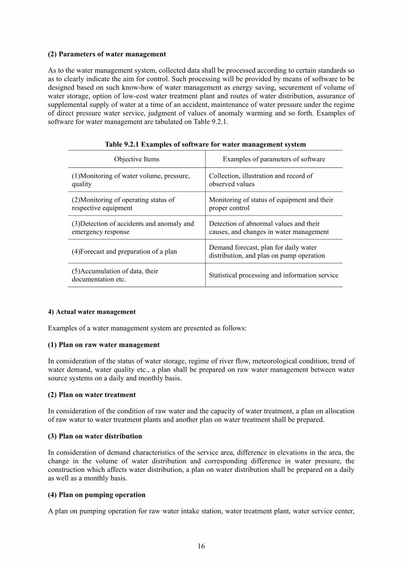
(2) Parameters of water management
As to the water management system, collected data shall be processed according to certain standards so as to clearly indicate the aim for control. Such processing will be provided by means of software to be designed based on such know-how of water management as energy saving, securement of volume of water storage, option of low-cost water treatment plant and routes of water distribution, assurance of supplemental supply of water at a time of an accident, maintenance of water pressure under the regime of direct pressure water service, judgment of values of anomaly warming and so forth. Examples of software for water management are tabulated on Table 9.2.1.
Table 9.2.1 Examples of software for water management system
Objective Items Examples of parameters of software
(1)Monitoring of water volume, pressure, quality
Collection, illustration and record of observed values
(2)Monitoring of operating status of respective equipment
Monitoring of status of equipment and their proper control
(3)Detection of accidents and anomaly and emergency response
Detection of abnormal values and their causes, and changes in water management
(4)Forecast and preparation of a plan Demand forecast, plan for daily water distribution, and plan on pump operation
(5)Accumulation of data, their documentation etc.
Statistical processing and information service
4) Actual water management
Examples of a water management system are presented as follows:
(1) Plan on raw water management
In consideration of the status of water storage, regime of river flow, meteorological condition, trend of water demand, water quality etc., a plan shall be prepared on raw water management between water source systems on a daily and monthly basis.
(2) Plan on water treatment
In consideration of the condition of raw water and the capacity of water treatment, a plan on allocation of raw water to water treatment plants and another plan on water treatment shall be prepared.
(3) Plan on water distribution
In consideration of demand characteristics of the service area, difference in elevations in the area, the change in the volume of water distribution and corresponding difference in water pressure, the construction which affects water distribution, a plan on water distribution shall be prepared on a daily as well as a monthly basis.
(4) Plan on pumping operation
A plan on pumping operation for raw water intake station, water treatment plant, water service center,
17
booster station etc. shall be prepared on a daily or a weekly basis in consideration of demand characteristics of the service area, transmission capacity of water mains, capacity of pumps, capacity of power supply, existence of switching valves, water level of the service reservoir and so forth.
(5) Monitoring
Monitoring shall be performed in accordance with the water management plan.
Adjustment of the difference between the plan and the actual operation and fine tuning thereof
Detection of an accident and anomaly, response to them and order thereto
Exchange of information with the site by telephoning
Collection and notification of information on weather, an electrical accident and an accident related to
river water quality
Additionally, the following data are to be processed and used as reference material for water management and for policy-making:
Compilation of data on statistics etc.
Preparation of daily, monthly, annual reports etc.
9.2.3. Management of Treated Water Transmission and Distribution Facilities Operation
Treated water transmission and distribution facilities shall be operated in accordance with the principle of setting a high value on the most reliable water service. Thus it is needed that the function and capacity of the existing facilities are diagnosed and evaluated, and that they are replaced or improved based on such diagnosis and evaluation or the method of operation is changed. In case the method of operation is changed, comparison shall be made on water volume, pressure, quality, cost of operation etc. before and after such a change, and the magnitude of improvement shall quantitatively be measured so that the result of comparison is reflected to management of operation. Furthermore, demand forecast for treated water transmission and distribution shall be made and an operation plan shall be prepared based on such forecast so that appropriate monitoring can be undertaken.
1. Forecast of volumes of treated water transmission and distribution
Forecast of volumes of treated water transmission and distribution facilities is indispensable for planning of the operation of treated water transmission and distribution facilities.
As the method of forecast, based on the distribution water volume on the same date in the past similar to the condition for the forecast to be extracted from the values of water distribution volume for certain time period prior to the date of forecast, the forecast values are obtained after compensating the above vales with statistically processed figures for the day of the week, weather, temperature, such peculiar date as consecutive holiday, “Bon”(Buddhist festival of the dead) etc.
It is important for the forecasting system to be mainly composed of a forecasting model suitable for the purpose and the method of management planning; and possess a function, which can provide useful guidance for the operator, or with which the operator can himself judge and intervene.
2. Control of treated water transmission and distribution
Control of treated water transmission and distribution shall be carried out to secure water volume and proper water pressure compatible with changing distribution water volume based on the forecast of volumes of treated water transmission and distribution.
18
1) Control of treated water transmission and operation of the service reservoir
The control method of treated water transmission pumps is closely related with the control method of the service reservoir. Treated water transmission pumps shall be operated to maintain the water level of the service reservoir within the prescribed range based on forecast and experienced values.
As control methods of treated water transmission pumps, there are the unit control method, and the speed control method. The former is suitable to a system, of which head loss in the water main is small compared with the actual lift of pumping and in which changes in discharge volumes or pressure are allowed. The latter is fit for a system with big head loss in the water main compared with the actual lift and that in which the changes in flow is large and continuous operation is required, and in general used together with the unit control method.
The principle of the operation of the service reservoir is to maintain the output of the water treatment plant and the volume of treated water transmission as much at a fixed value as possible, and absorb the changes in the volume of water distribution by means of the capacity of the service reservoir as much as possible. Besides, it is important to maintain the water level in the service reservoir higher than the design water level so as to prepare for such an accident or disaster as failure of treated water transmission pumps etc.
2) Control of water distribution
The purpose of the control of water distribution is to maintain the water pressure in the distribution mains within the prescribed range even in case the water distribution flow is changed. As control methods, there are the constant pump discharge pressure method and the constant terminal pressure method, and both of them are performed by means of pump unit control, speed control, valve aperture control, or their combination.
Constant pump discharge pressure control is a control method to maintain the delivery pressure of the water distribution pump or the secondary pressure of the pressure reducing valve irrespective of changes in the water distribution flow. Constant terminal pressure control is a control method to maintain the water pressure at the end of distribution mains constant. In constant terminal pressure control, the actual terminal water pressure in a remote location is measured by telemetry so as to control the water pressure, or measuring the distribution water flow and pressure, the terminal water pressure is computed by means of an equation using head loss coefficient so that control is indirectly made, or control is undertaken by the combination of the two above.
3. Monitoring
For monitoring of treated water transmission and distribution facilities, monitoring of water quality, in addition to the ordinary monitoring of water volume and pressure, is important.
1) Monitoring of water volume and pressure
As forms of monitoring of water volume and pressure, one is conducted at a fixed interval and another one is always carried out. Under the fixed-interval monitoring, data are collected on a daily, weekly, monthly, or seasonal basis, so they are used for the improvement of operation method of the treated water transmission and distribution facilities and evaluation thereof since the locations and points of measurement can voluntarily be selected. Under the regular basis monitoring, data, which incessantly change, are collected so that feed-back is made to facility operation.
2) Monitoring of water quality
Monitoring of water quality is performed every day at fixed locations as one method, or always carried out by automatic water quality analyzers as another. Under fixed-location monitoring, function evaluation of treated water transmission and distribution facilities can be made by means of collection
19
of many monitoring items of water quality, which enables detailed monitoring. On the other hand, early detection of the occurrence of abnormal water quality will become possible by means of regular monitoring by automatic water quality analyzers.
4. Operation management
As a basis, operation management of treated water transmission and distribution facilities shall safely, rationally and economically be performed. On the other hand, however, attention shall be paid to the following matters in consideration of environmental conservation:
1) Treated water transmission pumps and transmission mains
Treated water transmission pumps shall be operated so that the volume of water transmission is to be made as constant as possible in consideration of the time regulation function of the service reservoir.
Since treated water transmission mains function as trunk distribution mains as well in many cases, treated water transmission mains and distribution mains shall progressively be divided so that exclusive treated water transmission mains are provided so as to aim at energy saving for treated water transmission pumps.
2) Service reservoir
In the case of a water utility with more than two service areas, detention time at a particular service reservoir is prolonged at times causing deterioration in water quality. In such a case, the need for making the size of the service area appropriate shall be considered, and it is also useful to install additional chlorine dosing equipment if it is difficult to change the size due to the topographical limitation etc.
Besides, it is important to conduct inspection and maintenance of the service reservoir at a fixed interval according to its structural characteristics. Particularly, inspection of its inside is normally carried out every several years when the inside is cleaned. In such an occasion, a study and inspection of the entire body of the service reservoir need to be undertaken including structural evaluation in terms of cracks etc., a study on the depth of erosion of steel plates, examination of the foundation, expansion joints, peripheral parts and so forth.
3) Water distribution pumps and distribution mains
Water distribution pumps shall possess function to be able to always follow the distribution water flow which largely changes depending on the season, day of week, hour, weather etc. As such, the pumps shall be operated utilizing data not only on the examination of such characteristics of the pump itself as the pressure, discharging flow, number of revolutions, existence of cavitations etc., but also the head loss in the distribution mains, terminal pressure, historical changes of distribution water volume and so on.
9.2.4. Water Distribution Control
Water distribution control denotes management of the supply of water by means of regulating flow and pressure in distribution mains by controlling the operation of pumps and valves according to changes in demand so that water can be served in prerequisite quality.
1. Proper water volume and pressure
Water needs to be uniformly served in the service area under proper pressure. The minimum dynamic water pressure shall be compatible with such local characteristics as a plan on the implementation of direct pressure water service etc. In addition, water distribution shall rationally be controlled so that water service can be made in accordance with the demand in the service area.
20
2. Control of water volume and pressure
As smooth water service and minimization of energy loss are required, water volume and pressure shall be controlled with the service area divided into blocks in accordance with the topography of the area and the capacity of the facilities. The control method of water volume and pressure shall be as follows:
1) Control by operation of valves
In case water volume and pressure controlled by valve operation, hourly changes shall adequately be studied and examined, and water volume and pressure before and after such valve operation shall be measured so that the result is clarified. Then, the aperture of valves etc. shall be recorded in a valve register, and, at the same time, the status of the valves shall be indicated so that examination thereof can easily be made on site.
2) Control by booster pumps and pressure reducing valves
A booster pump shall be installed in the area where appropriate water pressure cannot be obtained due to topographical restrictions; and pressure reducing valves etc. shall be placed, where water pressure is high, so as to appropriately control the pressure.
3) Control by improvement in water distribution mains
In case water volume and pressure are insufficient due to low capacity of distribution mains, the improvement in water volume and pressure shall be made by means of increasing the diameter of the mains, laying of new mains, mutual connection mains, duplication of the mains, formation of loops etc.
4) Response at the time of fire
The water pressure in the distribution mains shall be maintained so as not to become negative when fire hydrants are used at the time of fire. To this end, the water pressure on the hydrant shall at a fixed interval be measured and recorded.
3. Understanding of the status of water distribution
The water flow, pressure and quality in the service area change depending on the topographical condition, time zone, season etc. What is more, since the regime of water distribution changes along with the alteration in the condition of piping due to replacement of distribution mains etc., such changes need to precisely be identified.
1) The need for understanding of situation of water distribution
To effectively perform water distribution control, it is needed to correctly study water flow, pressure, length, ground elevation etc. of each water main beforehand.
In case actual measurement of flow in the distribution water mains is difficult, the area to be covered by the main shall be presumed and the flow is to be estimated from the water consumption in the area.
Additionally, claims from consumers in regard to insufficient water discharge, water quality etc. shall be treated not only by the respective incumbent office but also saved and stored as data by another particular office so that they can be used for maintenance and renewal.
2) Method for the identification of situation of water distribution
(1) Regular, fixed-interval and ad hoc measurement
As measurement methods, there are three methods in terms of the interval of measurement, namely, the regular measurement method, the fixed-interval measurement method and the ad hoc measurement
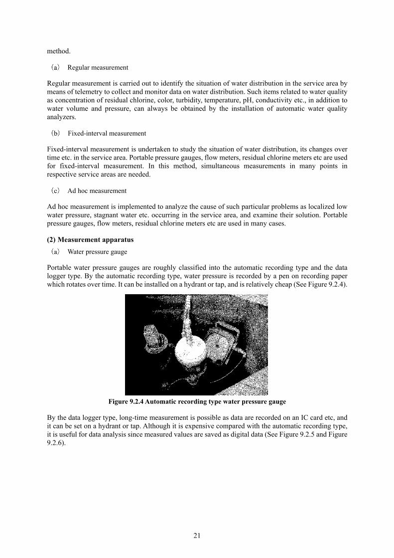
21
method.
Regular measurement
Regular measurement is carried out to identify the situation of water distribution in the service area by means of telemetry to collect and monitor data on water distribution. Such items related to water quality as concentration of residual chlorine, color, turbidity, temperature, pH, conductivity etc., in addition to water volume and pressure, can always be obtained by the installation of automatic water quality analyzers.
Fixed-interval measurement
Fixed-interval measurement is undertaken to study the situation of water distribution, its changes over time etc. in the service area. Portable pressure gauges, flow meters, residual chlorine meters etc are used for fixed-interval measurement. In this method, simultaneous measurements in many points in respective service areas are needed.
Ad hoc measurement
Ad hoc measurement is implemented to analyze the cause of such particular problems as localized low water pressure, stagnant water etc. occurring in the service area, and examine their solution. Portable pressure gauges, flow meters, residual chlorine meters etc are used in many cases.
(2) Measurement apparatus
Water pressure gauge
Portable water pressure gauges are roughly classified into the automatic recording type and the data logger type. By the automatic recording type, water pressure is recorded by a pen on recording paper which rotates over time. It can be installed on a hydrant or tap, and is relatively cheap (See Figure 9.2.4).
Figure 9.2.4 Automatic recording type water pressure gauge
By the data logger type, long-time measurement is possible as data are recorded on an IC card etc, and it can be set on a hydrant or tap. Although it is expensive compared with the automatic recording type, it is useful for data analysis since measured values are saved as digital data (See Figure 9.2.5 and Figure 9.2.6).

22
Figure 9.2.5 Data logger type water pressure gauge
Figure 9.2.6 Example of measured data
Flow meter
Portable flow meters are roughly classified into the ultrasonic wave type and the insert type. The ultrasonic wave type is installed on the exposed body of such water main as a water mains bridge since it needs to be fixed on the outside body of a water main (See Figure 9.2.7).
Figure 9.2.7 Ultrasonic wave type flow meter

23
Figure 9.2.8 Insert type flow meter
The insert type is an instrument to measure flow inserting a censor from a hydrant, a flange of an air-valve etc. as an uninterrupted operation. There also is a type of instrument which can be stowed inside a hydrant box (See Figure 9.2.8).
Residual chlorine meter
For the portable residual chlorine meter, measurement by the DPD (diethyl paraphenylene diamine) method is common. As the color of the solution turns from pink to reddish pink when residual chlorine reacts with DPD, the value (digital indication) of residual chlorine is measured comparing the color with the standard color columns.
4. Direct pressure water service and water distribution control
Since deterioration of water due to inappropriate maintenance of the receiving cistern has been a matter of concern in regard to water service with a cistern for medium- and high-rise buildings, water utilities and providers of water service by a receiving cistern became obliged to insure the safety and relief of the users in accordance with the clauses stipulated for their responsibility under the Waterworks Law revised in 2001.
Types of direct pressure water service are classified into the direct connection direct pressure type and the direct connection booster type. In the case of the direct connection direct pressure type, the minimum dynamic pressure of distribution mains needs to be raised, so, since water leakage is worried to increase, the direct pressure water service needs to be implemented in consideration of characteristics of the community and the capacity of water distribution facilities.
9.3. Service Reservoir, Standpipe, Elevated Tank and Regulating Reservoir 9.3.1. General
The service reservoir, standpipe and elevated tank possess the storage function to regulate the hourly changes of water distribution volume, and reduce the effect of an emergency. The standpipe and elevated tank have a function to regulate water pressure and protect water mains as well. The regulating reservoir is a storage facility for the bulk water supply utility to store treated water so as to regulate its water transmission operation.
24
9.3.2. Service Reservoir
1. Operation and management
When operating the service reservoir, it is needed to precisely forecast the changes in demand, rationally and efficiently carry out its operation, and also pay attention to water quality management.
Especially as for water quality, in case the retention time in the service reservoir is long, it is cautioned that the contents of residual chlorine in treated water will diminish resulting in shortage in residual chlorine at the fringe of the service area. Therefore it is needed to construct facilities for monitoring of water pressure and volume in various points in the service area so as to feed back to the operation of the reservoir.
1) Operation
The following points shall be observed when operating the service reservoir.
(1) Operation within the effective water depth
Operation of the service reservoir shall be conducted between the lowest water level (L.W.L.) and the highest water level (H.W.L.) of the effective storage. Prior to the peak demand time zone, water distribution shall be carried out with the service reservoir at the water level, which provides sufficient storage to meet the demand; and, in case the reservoir has certain room to spare in its storage, its operation shall be undertaken with its water level in consideration of an accident. Given this, the water level of the service reservoir shall at all times be monitored so that water does not overflow. As for monitoring of water level, different types of level gauges shall be installed in consideration of an accident.
The distance from the lowest water level of the reservoir to the center of the outlet pipe shall be set more than twice its diameter so that air or sediments are not sucked in.
(2) Management of residual chlorine in the treated water received by the service reservoir
The division of responsibility for management of water quality between the water supplier and its recipient shall clearly be established under an agreement etc. so that the concentration of residual chlorine needs to be controlled through consultation with both parties. Equipment for additional dosing of such a chlorine agent as sodium hypochlorite shall be installed depending on the situation.
2) Management
(1) Water level
Water level in the service reservoir shall be measured by a level gauge. Its operation shall remotely be monitored by means of a telemeter etc. so as to manage rationally and efficiently.
(2) Volume of water distribution
Daily volume of water distribution and its hourly changes shall be recorded for the control of water distribution and the future plan. For this purpose, automatic recording flow meter shall be installed to record instantaneous flow and cumulative flow, or remote monitoring of flow shall be undertaken by a telemeter etc.
(3) Residual chlorine in the vicinities of the inlet and outlet mouths
Residual chlorine shall at a fixed interval be measured by the DPD method to maintain the required concentration of residual chlorine at the terminal point of water distribution mains. Fixed-interval calibration of apparatus shall be made in case continuous measurement is conducted by automatic water

25
quality analyzers.
(4) Items to be observed at the time of cleaning the service reservoir
In case water is drained from the service reservoir to a river when it is cleaned, notification shall be made to the administrator of the river, and the section of the channel, inclination, condition of vegetation etc. of the river, to which the water is discharged, shall be studied so that no trouble is to be caused. Measures for prevention of scouring shall be made around the outfall mouth in case a large volume of water is discharged. Enough caution shall also be paid to accidents resulting in human casualties.
Additionally, dechlorination by a neutralizer etc. is to be implemented in case there is a fear of the occurrence of chlorine odor or kill of fish.
2. Inspection and maintenance
Inspection and maintenance are important work to properly carry out operation and maintenance, and consist of daily inspection to be done usually, fixed-interval inspection, and special inspection to be performed right after a disaster. If an anomaly, deterioration or damage is identified by inspection, its cause shall be investigated and it must quickly be repaired or refurbished.
Furthermore, the result of inspection and refurbishment shall be saved in an appropriate method to be utilized for forecast of deterioration and so on.
1) Inspection of the main structure
(1) Function evaluation and diagnosis of the structure of the service reservoir
In case function evaluation of concrete structures is performed, items to be studied are: cracks in concrete, which may cause pollution of water from outside, and existence of leakage from expansion or construction joints. Besides, cases of the neutralization of concrete and corrosion of reinforcing steel bars have been reported; and damage by salt or frost progresses depending on the location of construction.
The result of the study shall be the data to be used for such evaluation of the degree of deterioration as determination of allowable stress when diagnosing durability and resistance to an earthquake of the structures.
Although function evaluation of steel structures is basically the same with that of concrete structures, especially, existence of corrosion and status of welded points of such structural material as steel materials shall be studied. As steel materials are in general protected by coating, the status of their deterioration is judged by means of the measurement of their thickness and the examination of welded points. Rational diagnosis shall be conducted through selection of the study method suitable to its location and required accuracy.
What is more, in case a metal pipe runs through a reinforced concrete structure, attention shall be paid to the existence of corrosion of the pipe by macro-cell phenomenon.
(2) Maintenance of concrete structures
In case deterioration etc. of a concrete structure is identified by its inspection, detailed examination shall be carried out to find its cause and implement measures for repair, reinforcement and so forth as required.
(3) Frequency of inspection
The frequency of inspection of the inside of a service reservoir shall be one year after its inauguration since faults due to the design and construction are apt to appear in the initial period, and can be repaired quickly; and the frequency thereafter shall be determined with reference to other similar structures.

26
2) Repair
When repairing, it is important to precisely understand the details of damage, and investigate its cause. Depending on the result, the method of repair and reinforcement shall be studied, and their urgency shall be judged.
(1) Repair of concrete
Concrete structures get aged by developing cracks and neutralization due to environmental condition etc.
Since the durability of concrete structures is largely affected by cracks in concrete, a study shall elaborately be conducted specially from this point of view. Even if the degree of cracks is not affecting the structure itself, they may lead to such damage as corrosion of steel materials, leakage, freezing and thawing etc. resulting in impairment of its durability, function and appearance.
The specific method and equipment for diagnosis are presented in “Reference 9.1”.
[Reference 9.1] Method of testing deterioration of concrete structures
Alkaline aggregates reaction, neutralization of concrete, salt damage, frost damage etc. are mainly considered the causes of deterioration in reinforced concrete.
A study on deterioration shall be conducted from the points of view of corrosion of reinforcing bars, loose concrete surface, and condition of cracks. The items of measurement include the depth of neutralization of concrete, contents of salt, measurement of the tensile strength of the surface, measurement of strength by means of a Schmidt Hammer etc., detection of locations of defective parts using the ultrasonic wave transmission method, measurement of the position of reinforcing bars and the thickness of cover of reinforcement by a magnetic induction method and so forth. Examples of testing equipment and testing items of concrete structures and testing methods of concrete structures are illustrated on Table 9.1.1 and Reference Table 9.1.2.
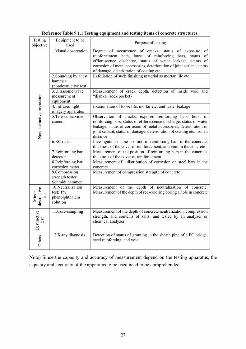
27
Reference Table 9.1.1 Testing equipment and testing items of concrete structures
Testing objective
Equipment to be used
Purpose of testing N
onde
stru
ctiv
e in
spec
tion
1.Visual observation Degree of occurrence of cracks, status of exposure of reinforcement bars, burst of reinforcing bars, status of efflorescence discharge, status of water leakage, status of corrosion of metal accessories, deterioration of joint sealant, status of damage, deterioration of coating etc.
2.Sounding by a test hammer (nondestructive test)
Exfoliation of such finishing material as mortar, tile etc.
3.Ultrasonic wave measurement equipment
Measurement of crack depth, detection of inside void and “djanka”(rock pocket)
4. Infrared light imagery apparatus
Examination of loose tile, mortar etc. and water leakage
5.Telescopic video camera
Observation of cracks, exposed reinforcing bars, burst of reinforcing bars, status of efflorescence discharge, status of water leakage, status of corrosion of metal accessories, deterioration of joint sealant, status of damage, deterioration of coating etc. from a distance
6.RC radar Investigation of the position of reinforcing bars in the concrete, thickness of the cover of reinforcement, and void in the concrete
7.Reinforcing bar detector
Measurement of the position of reinforcing bars in the concrete, thickness of the cover of reinforcement
8.Reinforcing bar corrosion meter
Measurement of distribution of corrosion on steel bars in the concrete
9.Compression strength tester: Schmidt hammer
Measurement of compression strength of concrete
Min
or
dest
ruct
ive
test
10.Neutralization test: 1% phenolphthalein solution
Measurement of the depth of neutralization of concrete; Measurement of the depth of red-coloring boring a hole in concrete
Des
truc
tive
te
st
11.Core-sampling Measurement of the depth of concrete neutralization, compression strength, and contents of salts; and tested by an analyzer or chemical analyzer
Oth
ers 12.X-ray diagnosis Detection of status of grouting in the sheath pipe of a PC bridge,
steel reinforcing, and void
Note) Since the capacity and accuracy of measurement depend on the testing apparatus, the
capacity and accuracy of the apparatus to be used need to be comprehended.
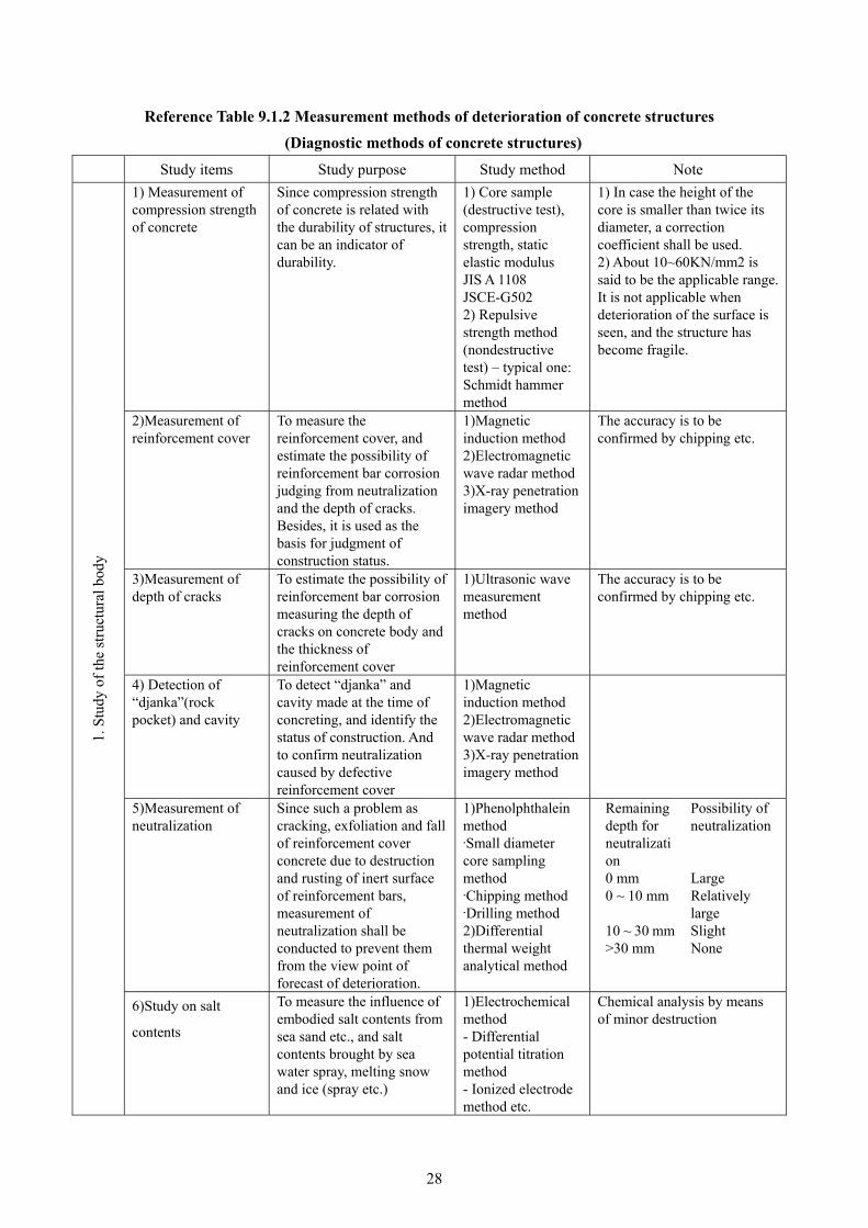
28
Reference Table 9.1.2 Measurement methods of deterioration of concrete structures
(Diagnostic methods of concrete structures)
Study items Study purpose Study method Note
1. S
tudy
of
the
stru
ctur
al b
ody
1) Measurement of compression strength of concrete
Since compression strength of concrete is related with the durability of structures, it can be an indicator of durability.
1) Core sample (destructive test), compression strength, static elastic modulus JIS A 1108 JSCE-G502 2) Repulsive strength method (nondestructive test) – typical one: Schmidt hammer method
1) In case the height of the core is smaller than twice its diameter, a correction coefficient shall be used. 2) About 10~60KN/mm2 is said to be the applicable range. It is not applicable when deterioration of the surface is seen, and the structure has become fragile.
2)Measurement of reinforcement cover
To measure the reinforcement cover, and estimate the possibility of reinforcement bar corrosion judging from neutralization and the depth of cracks. Besides, it is used as the basis for judgment of construction status.
1)Magnetic induction method 2)Electromagnetic wave radar method 3)X-ray penetration imagery method
The accuracy is to be confirmed by chipping etc.
3)Measurement of depth of cracks
To estimate the possibility of reinforcement bar corrosion measuring the depth of cracks on concrete body and the thickness of reinforcement cover
1)Ultrasonic wave measurement method
The accuracy is to be confirmed by chipping etc.
4) Detection of “djanka”(rock pocket) and cavity
To detect “djanka” and cavity made at the time of concreting, and identify the status of construction. And to confirm neutralization caused by defective reinforcement cover
1)Magnetic induction method 2)Electromagnetic wave radar method 3)X-ray penetration imagery method
5)Measurement of neutralization
Since such a problem as cracking, exfoliation and fall of reinforcement cover concrete due to destruction and rusting of inert surface of reinforcement bars, measurement of neutralization shall be conducted to prevent them from the view point of forecast of deterioration.
1)Phenolphthalein method ·Small diameter core sampling method ·Chipping method ·Drilling method 2)Differential thermal weight analytical method
Remaining depth for neutralization
Possibility of neutralization
0 mm Large 0 ~ 10 mm Relatively
large 10 ~ 30 mm Slight >30 mm None
6)Study on salt
contents
To measure the influence of embodied salt contents from sea sand etc., and salt contents brought by sea water spray, melting snow and ice (spray etc.)
1)Electrochemical method - Differential potential titration method - Ionized electrode method etc.
Chemical analysis by means of minor destruction

29
2)Absorption photometry - Mercuric thiocyanide method- Silver chromate method
7)Study on alkaline-
silica reaction
Cracks brought by alkaline-silica reaction are roughly classified into macroscopic cracks occurring in the vicinity of the surface and microscopic cracks occurring inside. This study is to be carried out since the former affects corrosion of reinforcing bars; and the latter influences the tenacity of the structure.
1)Visual observation - Confirmation of status of cracking 2)Progressive measurement - Growth in width of cracks - Extent of expansion; value of displacement 3)Core test - Dynamic test - Measurement of alkaline silica gel - Measurement of remaining value of expansion
1)Direction of binding, tortoiseshell shape, the direction to split the thickness of members, displacement, deformation, discoloring, difference in level, pop-out 2)Contact gauge method, displacement meter 3)Compression strength, elastic modulus etc. - Chemical components analysis, uranyl acetate fluorescence method - UCH DD2 method, Canadian method, Danish method
8)Study on the status of corrosion of reinforcing bars
To measure the possibility of corrosion of reinforcing bars in the concrete
1)Natural potential method
-350mv E Highly corrosive -250mv E > -350mv Moderately corrosive -150mv E > -250mv Slightly corrosive E > -150mv Not corrosive
2.E
xter
ior
fini
sh
1)Analysis and study on cracks on walls, exposed reinforcing bars and sticking stains
As they are the most common items for diagnosis of deterioration of structures, the present magnitude of deterioration of the structure is synthetically evaluated by observing the present status appearing as deterioration phenomenon.
1)Visual observation 2)Telescopic video system
2)Study on bond strength of exterior finishing materials
The magnitude of deterioration of exterior finishing materials, which possesses the two functions of protection of the body and make-up, is to be evaluated in terms of its bond strength.
1)Tensile test in accordance with the method established by the Building Research Institute
Minor destructive test
3)Study on loose exterior finishing material
Loose parts of such exterior finishing materials as mortar and tiles shall be examined to identify the parts in danger of fall and determine the area in need of resin treatment.
1)Hammer sounding 2) Infrared light imagery equipment
In the case of infrared light imagery equipment, suitable conditions shall be examined.
3.W
ater
proo
fing
on
roof
1)Study on status of deterioration of waterproof sheet
To identify the status of deterioration of the sheet, and determine the area for repair and timing for its replacement
1)Visual observation 2)Tensile test using samples
Provision of a note on the mode of walking on the roof (in case there is no protective coating)

30
(2) Repair of expansion joints
On expansion joints of concrete, elastic water stop plates, which are suitable for maintenance of water tightness and extent of expansion and contraction, are used, and, additionally, the surface of the joints is sealed with sealant in many cases. As the material of the water stop plate, although there are PVC-made ones and rubber-made ones, there are examples of installation with more water tight Isobutylene-isoprene rubber (IIR) or water-expandable rubber or their combination.
Even if there is no water leakage after initiation of a service reservoir, it is also considered that water leakage may occur due to loose contact of the water stop plate with concrete due to deterioration as it ages, and escape, cracking etc. of the water stop plate caused by excessive displacement etc. as a result of an earthquake and uneven subsidence. In case the water tightness of the service reservoir is not secured, its function is impaired so such a defect shall quickly be amended.
(3) Repair of defective concrete
In case the insufficient section of members due to exfoliation of concrete surface, its deterioration etc., and the need for protection of reinforcing bars come into existence, the defective concrete shall be chipped off so that that part is replaced with new concrete etc.
(4) Waterproofing of the inside and outside surfaces of the service reservoir
Waterproofing of the inside of a service reservoir is implemented to inhibit neutralization and deterioration of concrete surface, which are caused by treated water or chlorine ion. However, the progress of deterioration of waterproof coating film is subject to the type of coating material and workmanship of its execution. As the deterioration of coating film arises in the forms of bulging, cracking, exfoliation etc., the condition of the coating film shall be examined and recorded through a daily inspection.
The specification for waterproofing has been changed from waterproof mortar, permeable inorganic paint, and emulsion family epoxy to waterproof coating by non-solvent type epoxy. Repair of inside waterproofing shall systematically be carried out in accordance with the nature of the waterproof agent.
Additionally, outside waterproofing shall be repaired based on such a study as visible observation of deterioration of coating, hammer sounding etc.
(5) Influence of alkaline aggregate reaction (ASR)
Cracks by alkaline aggregate reaction externally appear in parallel to the binding direction of the member, in the direction to split the thickness of the member, in tortoiseshell-like form in case the binding force is small. They typically have no tendency to deeply penetrate, reach to the depth of several centimeters, have broad width on the surface, and form a difference in level at the lower position.
Maintenance of structures, which are undergoing the influence of alkaline aggregate reaction, shall be carried out while inspecting them at a fixed interval to check changes in cracks.
3) Study on water leakage
Leakage from the service reservoir is not only loss of treated water but induces the intrusion of wastewater from outside depending on the condition of the groundwater around the reservoir. As such, in addition to leakage detection survey in a fixed interval, a leakage detection study also needs to be conducted right after an earthquake or disaster of storm and flood. As the method of a leakage study, there is a method to observe the drop in water level after fully filling the reservoir and closing inlet and outlet valves.

31
4) Inspection and maintenance of ancillary facilities
An inlet pipe, an outlet pipe, a drain pipe, a bypass pipe, an interconnecting pipe etc. and valves are installed on the service reservoir. There are many valves such as an emergency shut-off valve, which are not in use in normal times. They shall be inspected at a fixed interval, and must be repaired right away if they are malfunctioning. Likewise, in case backflow prevention valves are installed, their function shall be checked at a fixed interval.
5) Inspection and maintenance of instruments and warning devices
Level gauges, warning devices, automation apparatuses etc. shall be inspected and kept up according to standards of the prescribed functional checking items. Flow meters shall be inspected for their accuracy at a fixed interval, and calibrated so that precise values are always indicated.
3. Prevention of pollution and safety measures
To secure the safety of water quality, attention shall be paid to prevention of pollution on the service reservoir.
1) Prevention of intrusion of rainwater etc.
In a location where there is a risk for the service reservoir to be inundated by a heavy rain, it needs to be protected by an embankment etc.
Besides, the overflow pipe, manhole, entrance of inspection gallery, sampling hole, ventilation unit, level gauge, drain pipe etc. shall be protected from external invasion by trash, rainwater, wastewater etc.
2) Off limits
Fences shall be built around the service reservoir so that ordinary persons do not enter in the premises without permission, and items to be observed etc. in the premises shall be posted at the entrance.
Furthermore, such places as the manhole and inspection gallery, where people can enter from outside, shall always be locked so that persons except for an official in charge cannot freely enter.
3) Provision of drainage
Drainage facilities shall be provided so that rainwater etc. does not stagnate in the premises. In case toilets etc. are located, they shall be so structured that wastewater does not leak, and need to be managed properly.
4. Cleaning and disinfection
For cleaning and disinfection of the service reservoir, reference 7.9.3 Chlorination of tap water.
9.3.3. Standpipe and Elevated Tank
1. Operation and management
For operation and management of the standpipe and elevated tank, reference 9.3.2 1. Operation and management.
2. Inspection and maintenance
As to painting of the steel standpipe and elevated tank, their main body, subiculums etc. shall be

32
inspected at a fixed interval, and their exterior surfaces shall be repainted every 3 to 5 years depending on the condition. As to painting work on inside surfaces, sufficient attention shall be paid for the safety of scaffolding and prevention of poisoning by organic solvent etc.
9.3.4. Regulation reservoir (Annotation is omitted.)
9.4. Treated Water Transmission Pumping Station, Distribution Pumping Station and Booster Pumping Station
9.4.1. General
The pumping station consists of composite facilities with mechanical, electrical, instrumental equipment, civil and architectural facilities, and the centralized control method and automation method are adopted. When operating and maintaining a pumping station, its structure, the method of operation and the system of management shall be well understood, and inspection and maintenance shall be implemented at a fixed interval while making efforts to prevent an accident.
In case a pumping station is operated in an unmanned method using a remote monitoring management system, duplicated power receiving or in-house power generation for emergency purpose etc. shall be provided; and such a measure against power failure as a DC power source shall be employed.
9.4.2. Treated Water Transmission Pumping Station
1. Operation and management
Operation and control method, monitoring items of the treated water transmission pumping station etc. vary depending on the size of such facilities as the service reservoir, standpipe etc. to which water is conveyed. The water pressure and flow in the water main, the water level in the service reservoir etc. shall be monitored by a centralized control system to carry out proper and rational operation suitable for the contents of the objective facilities.
1) Operation and monitoring
(1) Monitoring of water level
Treated water transmission pumps are operated based on the water level of the service reservoir, so the level gauge needs to be a type of remote indication.
There are the float type, differential pressure type, ultrasonic wave type etc. as the level gauge. In case duplicated level gauging system is adopted against an accident by lightning etc., different types of level gauges shall be installed.
(2) Control of treated water transmission flow
In case the number of units of pumps increased or decreased, or the aperture of delivery valves is regulated to change the water transmission flow, the operation shall be conducted while watching the pressure gauges and flow meters.
It is cautioned that red water at times occurs if the flow velocity in the water main is abruptly increased; or that surging (water hammer) arises if pumps are rapidly closed. As a measure to alleviate water hammer to be caused by power failure or an accident, there is a method to install a flywheel and a slow closing check valve, or a surge tank on the water main (See Figure 9.4.1, and Figure 9.4.2.).

33
Figure 9.4.1 Maximum and minimum pressure lines caused by water hammer
Figure 9.4.2 Diagram of oscillation of water pressure at point P (right after the pump)
(3) Suction pressure
If the water level of a pump well or the suction pressure of a pump decreases, cavitations occur at times in the inside of the pump causing such a trouble as erosion or inability to transmit water. In case the pump is operated at more than the rated discharge, attention shall be paid to the suction pressure, operating noise and vibrations. This is a phenomenon (water column separation) which occurs when the water pressure becomes lower than -1.01 MPa, and then dissolved air in water separates from water to form bubbles. When the bubbles crash in the high pressure area downstream to dissolve into water, impulsive noise occurs in the pump and the control valve.
If this phenomenon continues for a long time, erosion progresses locally, and may result in damage in pump runners and perforation on pipe walls right downstream of the pump and valve.
(4) Alternate operation of pumps
Pumps including spare units shall alternately be operated so that any one of them can be operated at any time, and that specific pumps are not suspended for a long time. Especially, submersible motor pumps shall alternately be operated at a short interval since their overhaul is quickly needed when they break down.
2) Measurement and recording
(1) Water level
The water level of a pump well shall continuously or at a fixed interval be measured installing level
Head loss in water main Hydraulic gradient line Maximum pressure line
Check valveMaximum negative pressure
Service reservoir
Water mains profile
Minimum pressure lineA
ctua
l lif
t
Range for negative pressure to occur
Distance
Pump well
Tota
l lif
t Treated water transmission pump
Wat
er p
ress
ure
M
axim
um p
ress
ure
Time elapsed
Min
imum
pre
ssur
e
34
gauges and data obtained shall be recorded.
(2) Water pressure
To monitor abnormal water level in the pump well, breakdown of a pump, malfunction of treated water transmission mains etc., suction pressure and delivery pressure shall continuously or at a fixed interval be measured and recorded. Besides, a warning device shall be installed as preparation for the occurrence of abnormal water pressure.
(3) Water volume
A flow meter shall be installed on the treated water transmission pump so as to measure and record the water volume.
(4) Electric voltage, current and power
As for main equipment, their electric voltage, current, and temperature shall continuously or at a fixed interval be measured and recorded.
In addition, efficient operation needs to be maintained based on the calculation and record of the unit value of treated water transmission by means of measurement of power consumption of respective facilities.
1) Inspection and maintenance
(1) Data on inspection and maintenance
Data on inspection and maintenance shall be classified according to a check list, and precisely be analyzed so as to be effectively used for the prevention of an accident.
Examples of a check list are presented on Table 9.4.1 and Table 9.4.2.
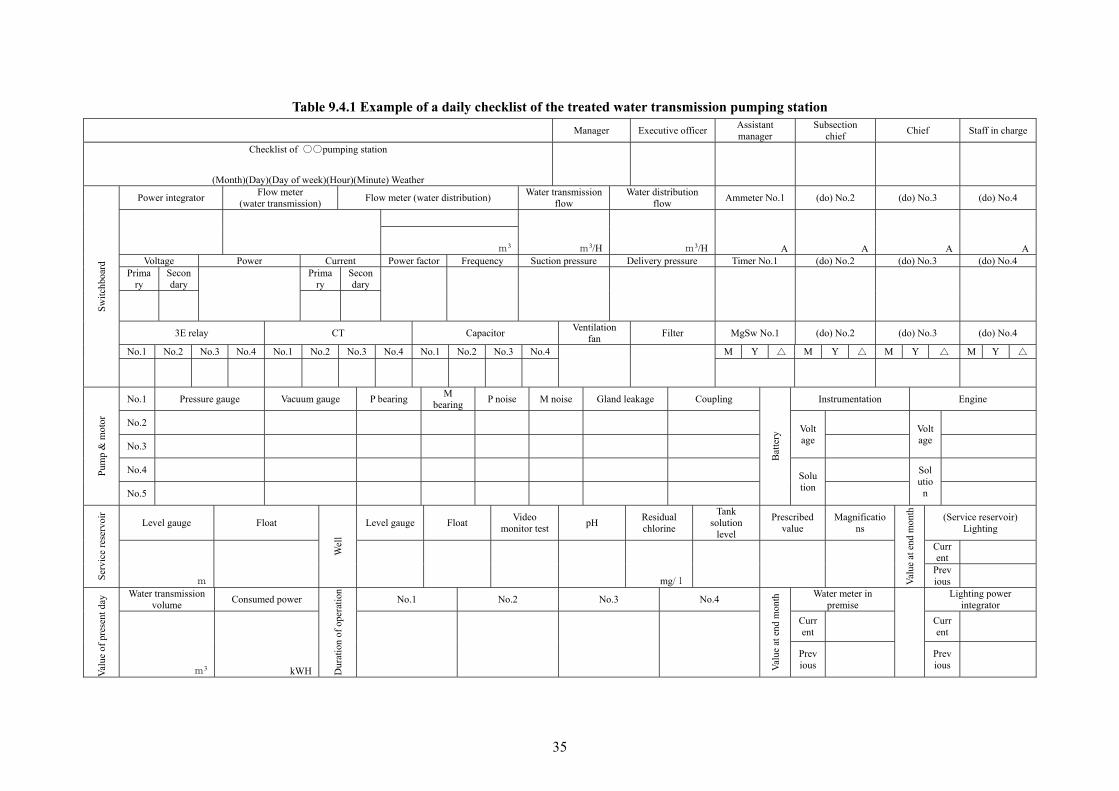
35
Table 9.4.1 Example of a daily checklist of the treated water transmission pumping station
Manager Executive officerAssistant manager
Subsection chief
Chief Staff in charge
Checklist of ○○pumping station
(Month)(Day)(Day of week)(Hour)(Minute) Weather
Sw
itch
boar
d
Power integrator Flow meter
(water transmission) Flow meter (water distribution)
Water transmission flow
Water distribution flow
Ammeter No.1 (do) No.2 (do) No.3 (do) No.4
m3/H m3/H A A A
A m3
Voltage Power Current Power factor Frequency Suction pressure Delivery pressure Timer No.1 (do) No.2 (do) No.3 (do) No.4 Prima
ry Secondary
Primary
Secondary
3E relay CT Capacitor Ventilation
fan Filter MgSw No.1 (do) No.2 (do) No.3 (do) No.4
No.1 No.2 No.3 No.4 No.1 No.2 No.3 No.4 No.1 No.2 No.3 No.4
M Y △ M Y △ M Y △ M Y △
Pum
p &
mot
or
No.1 Pressure gauge Vacuum gauge P bearing M
bearing P noise M noise Gland leakage Coupling
Bat
tery
Instrumentation Engine
No.2 Voltage
Voltage
No.3
No.4 Solution
Solutio
n
No.5
Ser
vice
res
ervo
ir
Level gauge Float
Wel
l
Level gauge Float Video
monitor testpH
Residual chlorine
Tank solution
level
Prescribed value
Magnifications
Val
ue a
t end
mon
th
(Service reservoir) Lighting
m
mg/l
Current
Previous
Val
ue o
f pr
esen
t day
Water transmission volume
Consumed power
Dur
atio
n of
ope
rati
on
No.1 No.2 No.3 No.4
Val
ue a
t end
mon
th Water meter in
premise
Lighting power integrator
m3 kWH
Current
Current
Previous
Previous

36
Date of measurement Year Month Day
Table 9.4.2 Example of a table for recording measurement of performance of pumps of a water transmission pumping station Staff in charge
Facility Pump Diameter mm、 Rating m3/min、 m Type
Motor Type Rating V, A
kw, P, rpm Manufacturer Manufacturer
Water transmission group
Unit number
# Serial
Number
Time of measure
ment
Aperture of valve Diameter
Type
Discharge Qp Lift (m) Water level
Actual lift Ha (m)
Unit power consumption
kwH/m3
Note Full scale of flow meter m3/h
Delivery side Hd
Suction side Hs
Difference between
gaugesHg
Difference in velocity
heads △hv
Total liftH
Arrival point Hr Pump well Hp Voltage
(V) ×
Current(A) ×
Power factor cos θ (%)
InputPmi (kw)
Signal value (V)
Converted value m3/h
HWL. LWL. Signal value
( )
Converted value (m)
Signal value
( )
Converted value (m)
(For site testing only)

37
(2) Pump well
Of pump facilities, it is easy to inspect those placed on the floor, but generally difficult to inspect those placed under the floor or in water. Therefore, the pump well shall be emptied as required so as to check the existence of unusual points and clean it.
In inspection, items to be checked are: existence of impurities in the pump well, anomalies in the main body of the well, function checking and zero point setting of the level gauge on the suction side etc. In the case of the vertical pump, the outside of the pump body shall be inspected; and in the case of the horizontal pump, checking shall be conducted according to such elements of the facility as status of erosion of the suction pipe, supporting metal fitting etc.
(3) Inspection of the pump house
Waterproofing of the roof
Since a leak from the roof is a cause of a serious failure of electric facilities, anomalies of roof waterproofing shall be inspected, and, if there is a fear of leak, the waterproofing shall quickly be repaired.
Ventilation of the pump room
A ventilation device shall be installed in the pump room so that the room temperature shall be kept less than 35~40℃ in summer. What is more, an air-conditioner shall be installed as required, and the temperature shall be so set as suitable to such equipment as remote control apparatuses.
2) Repair
The order, method etc. of repair work of the pump room shall adequately be examined in advance so that it can be carried out in a short period of time .
Moreover, the pump well shall have a structure, of which division is possible, and piping is so arranged that ordinary operation can be continued by means of switching of suction pipes and so forth.
Additionally, metal components shall be replaced by such corrosion-resistant material as stainless steel depending on needs.
3) Measures for cold districts
(1) Prevention of freezing
The pump room, which is possibly subject to freezing, shall be provided with heat insulation, and heating facility shall be installed so as not to lower the temperature lower than 5℃.
3. Measures against accidents
1) Anomaly of pumping station and measures against it
(1) Detection of an anomaly
Since at a time of anomaly more than two warnings may be generated by one cause, precise judgment is needed. An example of relationship between the indication by an instrument and the status of anomaly is presented on Table 9.4.3.

38
Table 9.4.3 Relationship between indication of instruments and status of anomaly Instrument
Phenomenon Pressure gauge Flow meter
Service reservoirLevel gauge
Steps to be taken
Burst of water mains
Abnormal drop Increase Decrease To stop pumps right away; to close Inlet valve on service reservoir
Failure of the pump
Abnormal drop Decrease Increase Switch to a standby pump unit
Over flow from service reservoir
No change No change Abnormal rise To stop immediately
Failure of the check valve
Reverse rotation of the pump with power failure To fully close delivery valve manually
Note) It is cautioned that response of the level gauge is slow in general.
(2) Status of anomaly and measure against it
In the case of an anomaly, the status of the site shall quickly be identified, an urgent measure suited to the situation shall be taken and related individuals shall be notified as required. In addition, a handling manual etc. shall be provided so that switching to spare units or manual operation can quickly and precisely be undertaken as preparation for the failure of automation equipment and control circuits; and operators shall be educated and trained for that cause.
What is more, to prepare for the case professional skills and urgent repair are needed, consideration shall also be paid for the method to entrust to manufacturers, and securement of minimum necessary spare parts.
2) Measures against power failure
Preparing for power failure caused by lightning etc., two-way power receiving or in-house power generation for emergency use shall be installed, a system to rapidly switch the power source shall be established, and the duplication of the power distribution system shall also be considered.
(1) Confirmation of time required for restoration of power
In the case of power failure, the time required for restoration, cause, estimated time of resumption etc. shall be confirmed quickly contacting the power company, related individuals shall be notified while preparing for restart of operation as soon as power supply recovers.
(2) Cautions to be practiced when restarting the operation
When restarting the operation after power failure, the process flow is to be increased slowly, and air is to be fully discharged from air-valves so that no adverse effects are brought about on the water mains.
Besides, the discharge of transmission pumps, pressure, electric current etc. shall be checked so that there is no change between these values and those at the normal times.
(3) Switching to the standby power supply
At a pumping station with a standby power supply, the power source shall quickly be switched to the standby power supply.
A trial run shall be made with the standby power supply units every month or so. And the stored volume of fuel tank shall be checked so that the emergency power supply securely works at a time of power

39
failure.
3) Measures against an emergency
(1) Preventive measures
For the pump house, and such equipment as electric motors, electric machinery and apparatus etc., preventive measures to ward off damage from inundation shall be provided at the ordinary times.
(2) Measures to be taken in case damage is sustained
An emergency response and restoration plan shall be made for the chain of command, order and method for an emergency call, public relations, emergency water service, steps of restoration work, a system of communications etc. on the prerequisite of a disaster.
4. Measures for energy conservation
Since measures for energy saving have been implemented so as to prevent global warming, it is required for the pumping station to be operated and managed in a manner to give only a small environmental stress.
Since water transmission pumps consume almost all parts of power consumption at a water transmission pumping station, measures to reduce the power consumption in the pumping system is the most useful.
1) Improvement in the method of operation
If a pump is operated with its delivery valve throttled, as the valve head loss becomes large, operation with its delivery valve fully open is good. Besides, in case there are more than two systems of treated water transmission to a service reservoir, the one, which has the favorable unit consumption rate, shall be put in operation.
2) Improvement in the machinery
The specification for a pump acquires certain allowance at each step of its planning, design and manufacture. In case the pump in commission has too large output, the diameter ends of its runner blades are to be cut short to operate at lower discharge so that the required power is reduced as a result of lowered head loss in the water mains.
5. Measures against noise and vibrations
As for the composite noise level of a pump and motor in operation 1m apart from the machinery shall be set as follows: less than 75dB for small pumps; less than 80dB for large pumps; and less than 50dB for outdoor type transformers.
Especially at night, efforts shall be made to prevent noise, which is caused at the times of starting and stopping of the pump, by excessive throttling of the delivery valve or by cavitations of the pump.
1) Prevention methods of noise and vibration
Noise and vibration generated from pumps and motors, and power equipment may cause nuisance to neighboring residents. When studying on the installation of measures for prevention of noise of a pumping station, noise and vibrations shall be measured in advance.
In case attenuation of noise over distance is not attained due to the small premises, such a measure shall be taken as sound absorbing inner walls aiming at the insulation of aerial propagation of sound to make the noise level at less than the allowable limits (See Figure 9.4.5). In addition, such an effective measure as the installation of a silencing box, and a vibration reduction bed, or replacement with a low-noise

40
machine shall be taken.
What is more, in case the noise caused by pulsatory pressure of pumping is large, it is recommended to reform the pump to a low pulsation one, or apply a measure for buffering pressure pulsation. However, since it is often difficult to reform the existing facility, adequate measures shall be taken at the time of construction.
Figure 9.4.5 Explanatory drawing of propagation routes of noise
Figure 9.4.9 Measures for prevention of solid body propagation of sound
Since vibration and pressure pulsation of the pump and motor conduct through the foundation stand, floor, wall, pipe body etc. to become solid body propagation sound and spread outside, complete isolation is useful to be provided between the foundation stand and the floor, between the floor and the structure, and the hole on the wall for the pipe to go through (See Figure 9.4.9).
Outer wall PC plank
Sprayed tile
Outdoor
Sprayed sound-absorbing material
H-steel for fabrication of the outer wall
Point of vibration measurement (after filling)
Rubber sheet Point of vibration measurement (before filling)
Vibration
Pump room
Filler thickness
Aerial propagationr
Ventilation blowerr Solid body propagation
Insulation
Staircase
Insulation Sound
Pump
Silencer

41
2) Measures related to pipe laying
Since the air in the water main amplifies the pressure pulsation of pumping resulting in noise generating from the water main, the earth cover of the laid water main shall be more than 1 m. Moreover, an air-valve shall be installed where air is expected to build up.
3) Ventilation
As the room temperature rises by heat generated from the switch board, motors and mechanical equipment which are installed indoor, such ventilation facilities as blowers shall be installed as required. Likewise, employing an inner cooling type or water-cooling type motor, the ventilation flow can largely be reduced.
6. Prevention of pollution and safety measures
1) Prevention of pollution in the pump well
In case there is leakage or inundation in the pump well, such a defect shall immediately be repaired; and the pump well shall be disinfected.
2) Prevention of pollution in the pump room
(1) House-keeping of the pump room
Special efforts shall be made for preventing pollution of the manhole in the pump room and the floor around the suction pipe; and the surroundings of the pump shall always be kept clean by means of providing drains around the pump and so forth.
(2) Blockage of the invasion of insects and small animals
Insects or small animals may at times invade the pump room, and cause trouble to equipment. Given this, mosquito net shall be set on openings and windows, and the doors shall not be kept open.
(3) Inundation from outside
Embankment for flood control, drains etc. shall be built for the pump room depending on situation. Water-tightness shall be secured on manholes and the floor around the suction pipe so that the pump well shall not be inundated from such locations.
Also, sufficient drainage pumping facilities etc. shall be provided against inundation,
3) Safety measures
It is important to provide measures assuming not only an accident caused by a natural disaster but all events including terrorism. Improvement of safety measures shall be made by means of off-limiting other individuals than the staff, strict locking of each entrance and exit, installation of monitoring and warning devices etc.
9.4.3. Water Distribution Pumping Station
1. Operation and management
In water distribution pumping, operation is carried out changing the number of pump units or the delivery pressure of the pumps to deal with the distribution flow which largely changes hourly. When conducting pumping operation, attention shall be paid not only to the hourly variation of the distribution flow but, especially, the midnight hourly flow which often become extremely small.

42
1) Operation and monitoring
(1) Control method
As the control methods of the water distribution pump, although there are the constant delivery pressure method, the constant end-point pressure method, the program control method etc., pumping shall properly be controlled, operated and monitored always paying attention to the changes of the suction water level or the suction pressure, the delivery pressure, the distribution flow etc. since there is a need to frequently regulate the flow.
(2) Operation method of a large capacity pump for small distribution flow
At a water distribution pumping station, a pump with the capacity based on a future plan is installed, but in a case it is operated at a small delivery flow in early stage of operation. In this case, the flow control method shall be determined in consideration of controllability, noise, vibrations, economic benefits etc.
If the period of operation is short, throttled operation by means of fixed orifice or valve aperture control is recommended. However, since the valve seat quickly wears in the case of valve aperture control, a high-performance butterfly valve, corn valve, sleeve valve etc., of which anti-cavitations property is high, shall be used; or control shall be performed by more than two valves installed in a series. As throttled valve operation tends to induce its failure, standby units shall be prepared.
If the period of operation is long, the measure to make the lift of the pump low by means of cutting pump runner blades short, or speed control and so forth is useful in consideration of operational efficiency. In the case of speed control, as the occurrence of electric wave interference is expected to be caused by noise, a preliminary survey and a measure against the incidence are needed.
2) Measurement and recording
(1) Water pressure
Pressure gauges shall be equipped on the composite delivery header of the water distribution pump and at the end of distribution mains, and measurement shall be made continuously or at a fixed time and recorded.
(2) Water volume
Measurement of water distribution volume is necessary to regulate the flow of water distribution pumps and plan the operation of water distribution, so flow meters shall be installed so that instantaneous and cumulative flow are indicated and recorded; or the results of continuous and fixed time measurement are recorded.
9.4.4. Booster pumping station
The suction head of a booster pump, which is installed on a water main to supplement short water pressure in a service area, shall be more than 0.15 MPa to prevent the occurrence of cavitations. Reference 9.4.2 Treated Water Transmission Pumping Station on the booster pumping station.
9.5. Treated Water Transmission Mains and Water Distribution Mains 9.5.1. General
Treated water transmission mains and water distribution mains are facilities to secure the safety of treated water, and reliably convey water to consumers. As their visual inspection is impossible since

43
they are buried in the earth, their maintenance is difficult.
Therefore, it is needed to collect information on the condition of the water mains and their functions, and properly implement their replacement and refurbishment.
To precisely identify a great volume of information on the water mains and properly utilize it, centralized management of information on water service and water distribution is important. By such provision, rapid response to an accident etc. and complaisant management to maintain water quality in the water main become possible.
9.5.2. Understanding of Information on Water mains
Information on water mains is indispensable for the diagnosis of water mains, and reflected to the plan for their replacement. Moreover, information on water volume, water pressure and water quality can also be used for operation and maintenance of water mains. Deliberately and systematically collecting and classifying precise information, and managing it in that its search, supplement and addition are easy, early restoration at the time of a disaster become possible.
1. Types of information on water mains
Information on water mains is related to pipe body, environment of pipe laying, hydraulics of
water mains, water quality, accident, claim, social information etc. To utilize it for systematic and
efficient water management in the future, necessary items of work are: preparation of a check list
for the collection of information, and provision of a registry of collected data and a filing system
for them. Types of information on water mains are presented on Table 9.5.1.
Table 9.5.1 Types of information on water mains Classification Contents
Information on pipe body
(1)Date of laying (2)Pipe material (type of joint, existence of lining and its type, method of welding at site, type of outside coating, type of inside coating) (3)Pipe wall thickness (4)Diameter and nominal diameter (5)Pipe length (6)Place of laying (7)No. of the water main (8)Ancillary attachments (gate valve, air-valve, pressure reducing valve, flow control valve, fire hydrant etc.) (9)Existence of polyethylene sleeves (10)Existence of cathodic protection (11)History of construction (Method of rehabilitation and date of its implementation) (12)Condition of the water mains (Status of corrosion and neutralization, damage on the outer surface, strength of pipe body, clogging by incrustation, nature of rust, status of deterioration of lining, condition of joints, status of corrosion of bolts) (13)Name of the contractor.
Information on environment of pipe laying
(1)Earth cover (2)Specifications for the pavement (3)Type of the lot occupied (road, riverbed etc.) (4)Volume of traffic (working load on road surface) (5)Soil quality (physical characteristics of the soil where the water main is buried, corrosiveness of the soil, existence of uneven subsidence) (6) Elevation of groundwater (7)Existence of buried objects of other enterprises (8)Existence of stray current
Hydraulics of water mains and information on water quality
(1)Water flow, pressure, quality (2)Direction of flow (3)Velocity coefficient
Information on accidents
(1)Date of occurrence (2)Its cause (3)Location (4)Details of the accident (status of leakage) (5)Method of repair (6)Influence of the accident
Claims (1)Date of claiming (2)Cause (3)Location of the incidence (4)Details of the claim (5)Method of response to the claim
Existence of social information
(1)Number of customers of water service (2)Water consumption (3)Status of urbanization (4)Existence of intensive water users (5)Existence of important facilities
44
2. Management of information on water mains
Information on water mains shall be collected from as-built drawings, cadasters of water service, records of accidents, data on other related enterprises, site surveys etc. There are control drawings, register books and mapping system as the method of management of collected information. Reference “9.8 Management of Information” as to these methods.
9.5.3. Management of drawings etc.
See 9.8.2 Management of drawings
9.5.4. Diagnosis and evaluation of water mains
1. Purpose of diagnosis and evaluation of water mains
The functions and capacity of treated water transmission and water distribution mains degrade due to their deterioration over time etc., so their replacement is needed. To efficiently and effectively carry out replacement of water mains, it is indispensable to judge such status of the water mains as their strength, durability and so forth. Examination of functions shall be undertaken at a proper timing, and replacement and refurbishment shall be implemented as preventive measures based on such an examination. As the effect of such efforts, maintenance of the functions of water mains and the improvement of consumer services shall be aimed.
2. Types of diagnosis of water mains
Types of diagnosis of water mains are classified into the indirect diagnosis and the direct diagnosis.
1) Indirect diagnosis
The indirect diagnosis is a method to analyze the deterioration and its cause in the function of water mains based on claims gathered through daily work of operation and maintenance, the record of accidents and their repair, the record on water volume, pressure, quality etc.; and predict the future changes. There are such methods of indirect diagnosis as follows:
Diagnosis based on the rate of accidents
Diagnosis is made by the value as the quotient of the number of all accidents of leakage and pipe burst in the section under examination divided by the length of the water mains and the number of years in commission (except for accidents due to ones caused by other enterprises). Examples of time in year of cast iron pipe in commission and occurrence numbers of accidents are shown in Figure 9.5.1.

45
Figure 9.5.1 Number of years in commission of cast iron pipe and occurrence numbers of
accidents (Binghamton City, N.Y.)
Qualitative diagnosis by time in year in commission
Examples of ranking of the magnitude of aging of cast iron pipe by the number of years etc. are presented on Table 9.5.2.
Table 9.5.2 Ranking of the grade of aging of cast iron pipe by the number of years etc. Main item
Ranking
With mortar lining?
Years in useC (year)
History of accidents
External cause
Evaluation Measure
I No - Large scale
accident - a large number of accidents
Risk: Large Potential of accident: Large
Replace as top priority
II -
- Middle scale accident - moderate number of accidents
Risk: Moderate
Potential of accident: Moderate
Replace as priority
III -
- Small scale accident - a small number of accidents
Risk: small Potential of accident:
Replace if possible
(Report on Survey of Cast iron pipe · steel pipe · hard PVC pipe diagnosis method: Japan Research Center of Pipes for Water Supply)
Diagnosis by the rate of incoming claims
Diagnosis is made by the value of the quotient of the number of all claims of low discharge, red water, low pressure etc. in the section under examination divided by the length of the water mains and the number of years in commission.
Vertical-casting cast iron pipe(Actual measurement) Sandmold centrifugal-span cast iron pipe (Actual measurement) Vertical-casting cast iron pipe(Estimate) Sandmold centrifugal-span cast iron pipe (Estimate)
Rat
e of
bur
st (
Tim
es/M
ile(
1.6
km)/
year
)
Years in commission
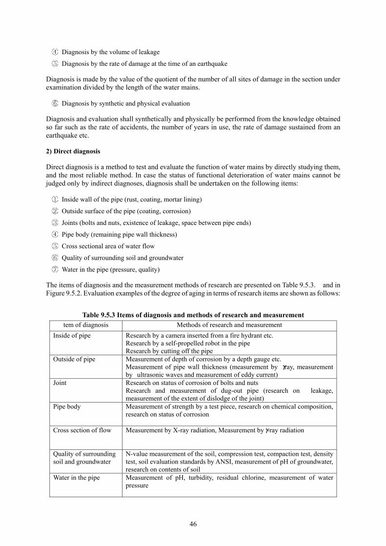
46
Diagnosis by the volume of leakage
Diagnosis by the rate of damage at the time of an earthquake
Diagnosis is made by the value of the quotient of the number of all sites of damage in the section under examination divided by the length of the water mains.
Diagnosis by synthetic and physical evaluation
Diagnosis and evaluation shall synthetically and physically be performed from the knowledge obtained so far such as the rate of accidents, the number of years in use, the rate of damage sustained from an earthquake etc.
2) Direct diagnosis
Direct diagnosis is a method to test and evaluate the function of water mains by directly studying them, and the most reliable method. In case the status of functional deterioration of water mains cannot be judged only by indirect diagnoses, diagnosis shall be undertaken on the following items:
Inside wall of the pipe (rust, coating, mortar lining)
Outside surface of the pipe (coating, corrosion)
Joints (bolts and nuts, existence of leakage, space between pipe ends)
Pipe body (remaining pipe wall thickness)
Cross sectional area of water flow
Quality of surrounding soil and groundwater
Water in the pipe (pressure, quality)
The items of diagnosis and the measurement methods of research are presented on Table 9.5.3. and in Figure 9.5.2. Evaluation examples of the degree of aging in terms of research items are shown as follows:
Table 9.5.3 Items of diagnosis and methods of research and measurement tem of diagnosis Methods of research and measurement
Inside of pipe Research by a camera inserted from a fire hydrant etc. Research by a self-propelled robot in the pipe Research by cutting off the pipe
Outside of pipe Measurement of depth of corrosion by a depth gauge etc. Measurement of pipe wall thickness (measurement by γray, measurement by ultrasonic waves and measurement of eddy current)
Joint Research on status of corrosion of bolts and nuts Research and measurement of dug-out pipe (research on leakage, measurement of the extent of dislodge of the joint)
Pipe body Measurement of strength by a test piece, research on chemical composition, research on status of corrosion
Cross section of flow Measurement by X-ray radiation, Measurement byγ-ray radiation
Quality of surrounding soil and groundwater
N-value measurement of the soil, compression test, compaction test, density test, soil evaluation standards by ANSI, measurement of pH of groundwater, research on contents of soil
Water in the pipe Measurement of pH, turbidity, residual chlorine, measurement of water pressure

47
Figure 9.5.2 Measurement method of corrosion depth and corroded area
(1) Magnitude of deterioration based on the depth of corrosion of cast iron pipe
Measuring from the outside of the pipe, the degree of aging is evaluated by the depth of the corroded part. The diagnosis standards for ranking of aging of the body of cast iron pipe and measures against them are presented on Table 9.5.4.
Table 9.5.4 Diagnosis standards for ranking of aging of the body of cast iron pipe
(including ductile iron pipe) and measures against them
Ranking of degree of aging Definition Measure
I
Status showing penetrating corrosionDepth of corrosion >(Specified wall thickness – allowable wall thickness) Note 1)
Since the remaining pipe wall thickness is basically not assured, such an emergency measure as immediate replacement etc. is needed.
II
Status with the design safety factor of less than 1.0 (Specified wall thickness – allowable wall thickness) Depth of corrosion > {Specified wall thickness – allowable wall thickness – actual wall thickness (Safety factor 1.0 Note 2)}
Since the safety factor of 1.0 is not assured against static water pressure, surging pressure and earth pressure by an external force, early replacement is needed.
III
Status with the design safety factor of more than 1.0 and less than 2.0~2.5. {Specified wall thickness – allowable wall thickness – actual wall thickness (Safety factor 1.0 Note 2)} Depth of corrosion > {Specified wall thickness – allowable wall thickness – actual wall thickness (Safety factor 2.0~2.5 Note 3)}
Since the safety factor of 2.5 against static water pressure, and 2.0 against surging pressure and earth pressure by an external force are not assured, such detailed and synthetic diagnosis as increased examination points shall be undertaken. Furthermore, a replacement plan shall be established for particular water mains in consideration of their priority.
IV
Status with the design safety factor of more than 1.0 and less than 2.0~2.5 but corrosion depth exceeding the corrosion margin of 2.0 mm {Specified wall thickness – allowable wall thickness – actual wall thickness (Safety factor 2.0~2.5 Note 3)} Depth of corrosion >{Corrosion margin (2.0 mm)}
Since corrosion is expected to progress, diagnosis shall again be carried out within 10 years during this status of ranking.
V
Status with corrosion depth of less than the corrosion margin of 2.0 mm with some allowance Corrosion margin (2.0 mm) Depth of corrosion
Status that corrosion depth is less than the corrosion margin with some allowance.
Note 1): 1.0 mm in case the specified pipe wall thickness is less than 10 mm; and 10% of wall thickness in case it exceeds 10 mm.
Note 2): Computed pipe wall thickness with a safety factor of 1.0 against static water pressure, surging pressure, earth pressure and wheel load.
Note 3): Computed pipe wall thickness with a safety factor of 2.5 against static water pressure, and 2.0 against surging pressure, earth pressure and wheel load.
(Measurement of corrosion depth) (Measurement of corroded area) Depth gauge
Pipe body
Corroded portion Depth of corrosionPipe body
Pipe wall Pipe wall
Major
Minor Corrodedportion Depth of corrosion

48
(2) Degree of aging judged from the status of corrosion on the outside surface of steel pipe
Computing the period until leakage starts by perforation caused by damage on the outside of the coated steel pipe body or its corroded portion, the magnitude of deterioration is to be evaluated. The period
until leakage starts by corrosion perforation shall be computed by the following formula:
Maximum corrosion rate (CRm)=
Period up to perforation by corrosion (y)= (mm/year)
Ranking of aging of coated steel pipe is shown on Table 9.5.5.
Table 9.5.5 Ranking of aging of coated steel pipe
Ranking of aging Period up to perforation by
corrosion y (year) Evaluation
I y≦5 Measures are needed.
II 5<y≦10 Water main for attention with high priority
III 10<y Water main for attention
(3) Degree of aging judged by the status of corrosion of bolts and nuts
Measuring the status of corrosion of bolts and nuts, the magnitude of corrosion of the joint area is evaluated. Judgment examples of ranking of corrosion of bolts and nuts are presented in Figure 9.5.3 and diagnosis standards for ranking of aging is shown on Table 9.5.6.
Figure 9.5.3 Judgment examples of ranking of aging degree of bolts
Maximum depth of corrosion (mm) Time elapsed (year)
Original pipe wall thickness-Maximum depth of corrosion (mm) 最最 Maximum rate of corrosion (mm/year)
(year)
Bell mouth flange
(Situation at the time of burial)
(Corrosion on screw gaps)
(Significant reduction in bolt diameter) (Corrosion only on screw ridges) (No corrosion)
(Gland follower portion)
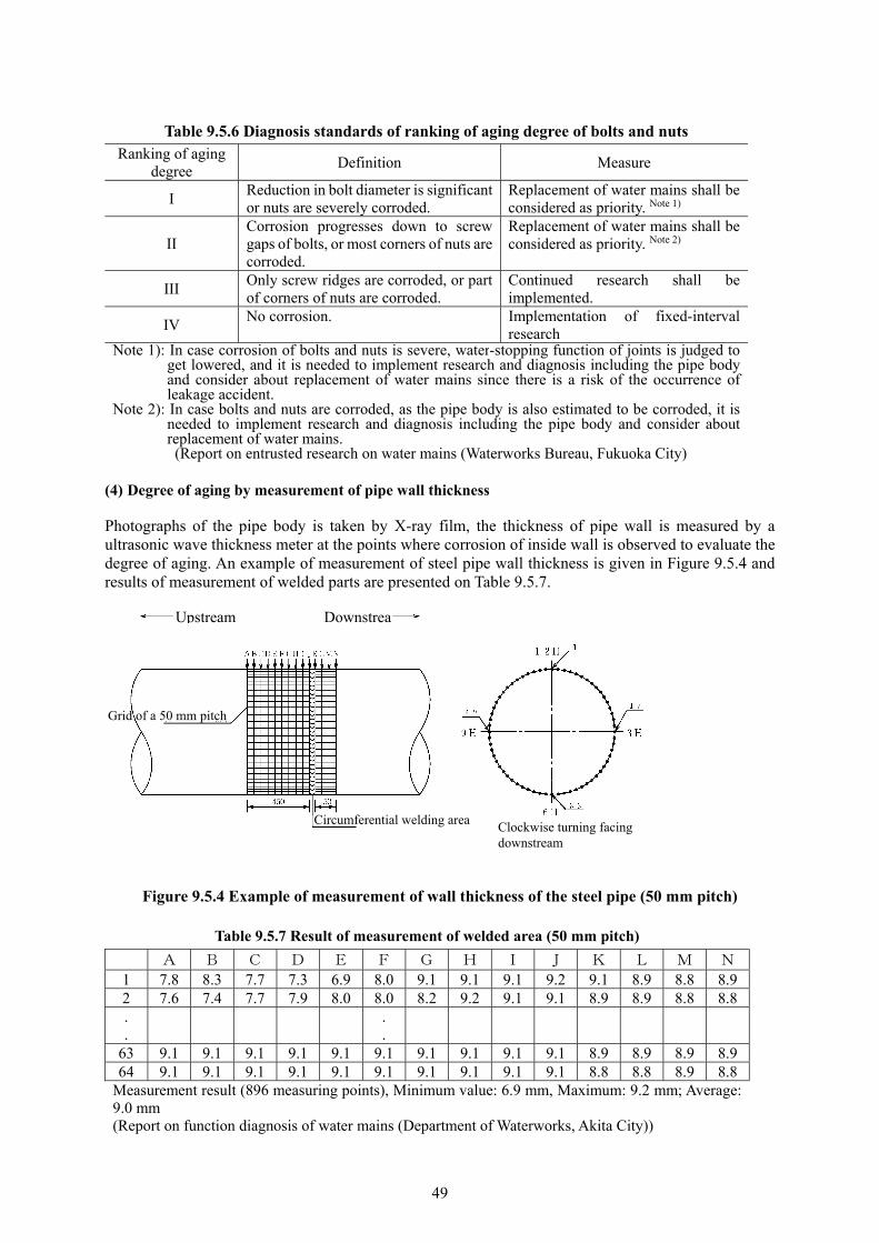
49
Table 9.5.6 Diagnosis standards of ranking of aging degree of bolts and nuts Ranking of aging
degree Definition Measure
I Reduction in bolt diameter is significant or nuts are severely corroded.
Replacement of water mains shall be considered as priority. Note 1)
II Corrosion progresses down to screw gaps of bolts, or most corners of nuts are corroded.
Replacement of water mains shall be considered as priority. Note 2)
III Only screw ridges are corroded, or part of corners of nuts are corroded.
Continued research shall be implemented.
IV No corrosion. Implementation of fixed-interval
research Note 1): In case corrosion of bolts and nuts is severe, water-stopping function of joints is judged to
get lowered, and it is needed to implement research and diagnosis including the pipe body and consider about replacement of water mains since there is a risk of the occurrence of leakage accident.
Note 2): In case bolts and nuts are corroded, as the pipe body is also estimated to be corroded, it is needed to implement research and diagnosis including the pipe body and consider about replacement of water mains. (Report on entrusted research on water mains (Waterworks Bureau, Fukuoka City)
(4) Degree of aging by measurement of pipe wall thickness
Photographs of the pipe body is taken by X-ray film, the thickness of pipe wall is measured by a ultrasonic wave thickness meter at the points where corrosion of inside wall is observed to evaluate the degree of aging. An example of measurement of steel pipe wall thickness is given in Figure 9.5.4 and results of measurement of welded parts are presented on Table 9.5.7.
Figure 9.5.4 Example of measurement of wall thickness of the steel pipe (50 mm pitch)
Table 9.5.7 Result of measurement of welded area (50 mm pitch)
A B C D E F G H I J K L M N 1 7.8 8.3 7.7 7.3 6.9 8.0 9.1 9.1 9.1 9.2 9.1 8.9 8.8 8.92 7.6 7.4 7.7 7.9 8.0 8.0 8.2 9.2 9.1 9.1 8.9 8.9 8.8 8.8. .
. .
63 9.1 9.1 9.1 9.1 9.1 9.1 9.1 9.1 9.1 9.1 8.9 8.9 8.9 8.964 9.1 9.1 9.1 9.1 9.1 9.1 9.1 9.1 9.1 9.1 8.8 8.8 8.9 8.8
Measurement result (896 measuring points), Minimum value: 6.9 mm, Maximum: 9.2 mm; Average: 9.0 mm (Report on function diagnosis of water mains (Department of Waterworks, Akita City))
Upstream Downstrea
Grid of a 50 mm pitch
Circumferential welding area Clockwise turning facing
downstream

50
3. Evaluation of diagnosis result
When preparing a water main replacement plan, synthetic evaluation shall be made identifying the difference in standards between the present status of the function of water mains and what is required in future based on the diagnosis result. Additionally, the following items also need to be examined on this occasion:
Priority of the water main
Consistency with the policy of the local government and its vision for water supply
Restrictions related to construction
Financial limitations
9.5.5. Replacement Plan of Water Mains
Since almost all parts of treated water transmission and distribution mains are buried under the roads, and influenced by water pressure, traffic loads etc., they are facing dangers of deterioration over time, corrosion by soil, cathodic erosion etc.
Since a large amount of cost and time for construction for replacement of treated water transmission and distribution mains are required, it is essential to plan replacement of water mains in consideration of measures against an earthquake based on the status of their deterioration, and systematically and successively implement the replacement work.
To this end, it is important to demonstrate the present status of the treated water transmission and distribution mains and benefits of the replacement of water mains to consumers to obtain their understanding and cooperation.
1. Purpose of replacement of water mains
Replacement of water mains is undertaken with aims for the prevention of leakage and burst of water mains due to their aging, avoidance of turbid water, restoration of flow capacity and so on. Secondly, there are many cases of water mains replacement for the purposes of reduction in the concentration of residual chlorine, spread of direct pressure water service, improvement in seismic resistance etc. from the view point of betterment of consumer services.
2. Steps of replacement of water mains
Replacement of water mains shall be implemented based on the diagnosis in accordance with 9.5.4 Diagnosis and Evaluation of Water Mains; and a plan for water mains replacement shall be made quantifying the priority of replacement in consideration of the importance of water management, relationship with buried objects of other enterprises, conditions for the occupation of roads and permission for the use of roads in addition to the above. Steps for the work of water mains replacement are shown in Figure 9.5.5.

51
Figure 9.5.5 System of water mains replacement
1) Basic study
For a basic study, diagnosis and evaluation of water mains are conducted based on the information related to the water mains. As to its method, reference 9.5.2 Identification of Information on Water Mains, and 9.5.4 Diagnosis and Evaluation of Water Mains.
Evaluation of water mains makes a basis for determination of the priority of water mains for replacement under the master plan through the respective processes of function evaluation and evaluation of the magnitude of influence.
2) Master plan
For a master plan, overall priority for replacement shall be determined based on the result of the basic study. Overall priority shall be determined out of objective water mains for replacement, which are selected in the evaluation of functions and degree of influence, synthetically judging from the magnitude of influence by an earthquake, evaluation of seismic resistance, major policies of respective water utilities, and their objective for replacement. The method for determining the priority of replacement based on overall physical evaluation and the importance of water mains is presented in Figure 9.5.6.
Information on water mains
Collection
Management
Replacement plan
Basic survey
Selection of evaluation method Evaluation of water mains (functions, effect)
Master plan
Overall priority Decision of water mains for replacement
Implementation plan
Decision of water mains replacement method
Implementation of the project
Plan for improvement of water mainsOther plans
Plan for improvement of roads Construction work of other related enterprises Others
Vision for water supply Guidelines for replacement of water supply facilities Guidelines for water supply utility
Flow of work Flow of information
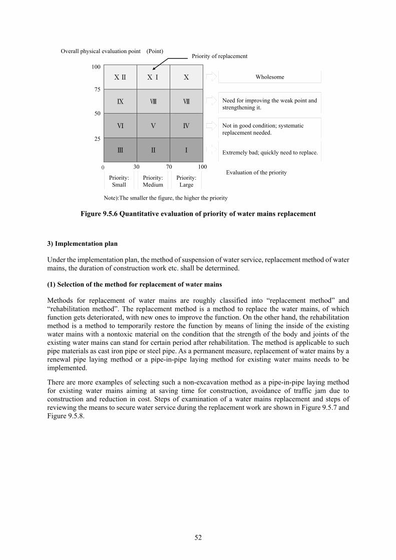
52
ⅩⅡ ⅩⅠ Ⅹ
Ⅸ Ⅷ Ⅶ
Ⅵ Ⅴ Ⅳ
Ⅲ Ⅱ Ⅰ
Note):The smaller the figure, the higher the priority
Figure 9.5.6 Quantitative evaluation of priority of water mains replacement
3) Implementation plan
Under the implementation plan, the method of suspension of water service, replacement method of water mains, the duration of construction work etc. shall be determined.
(1) Selection of the method for replacement of water mains
Methods for replacement of water mains are roughly classified into “replacement method” and “rehabilitation method”. The replacement method is a method to replace the water mains, of which function gets deteriorated, with new ones to improve the function. On the other hand, the rehabilitation method is a method to temporarily restore the function by means of lining the inside of the existing water mains with a nontoxic material on the condition that the strength of the body and joints of the existing water mains can stand for certain period after rehabilitation. The method is applicable to such pipe materials as cast iron pipe or steel pipe. As a permanent measure, replacement of water mains by a renewal pipe laying method or a pipe-in-pipe laying method for existing water mains needs to be implemented.
There are more examples of selecting such a non-excavation method as a pipe-in-pipe laying method for existing water mains aiming at saving time for construction, avoidance of traffic jam due to construction and reduction in cost. Steps of examination of a water mains replacement and steps of reviewing the means to secure water service during the replacement work are shown in Figure 9.5.7 and Figure 9.5.8.
Wholesome
Need for improving the weak point and strengthening it.
Not in good condition; systematic replacement needed.
Extremely bad; quickly need to replace.
Priority: Small
Priority: Medium
Priority: Large
30 70 100Evaluation of the priority
0
100
75
50
25
Overall physical evaluation point (Point) Priority of replacement
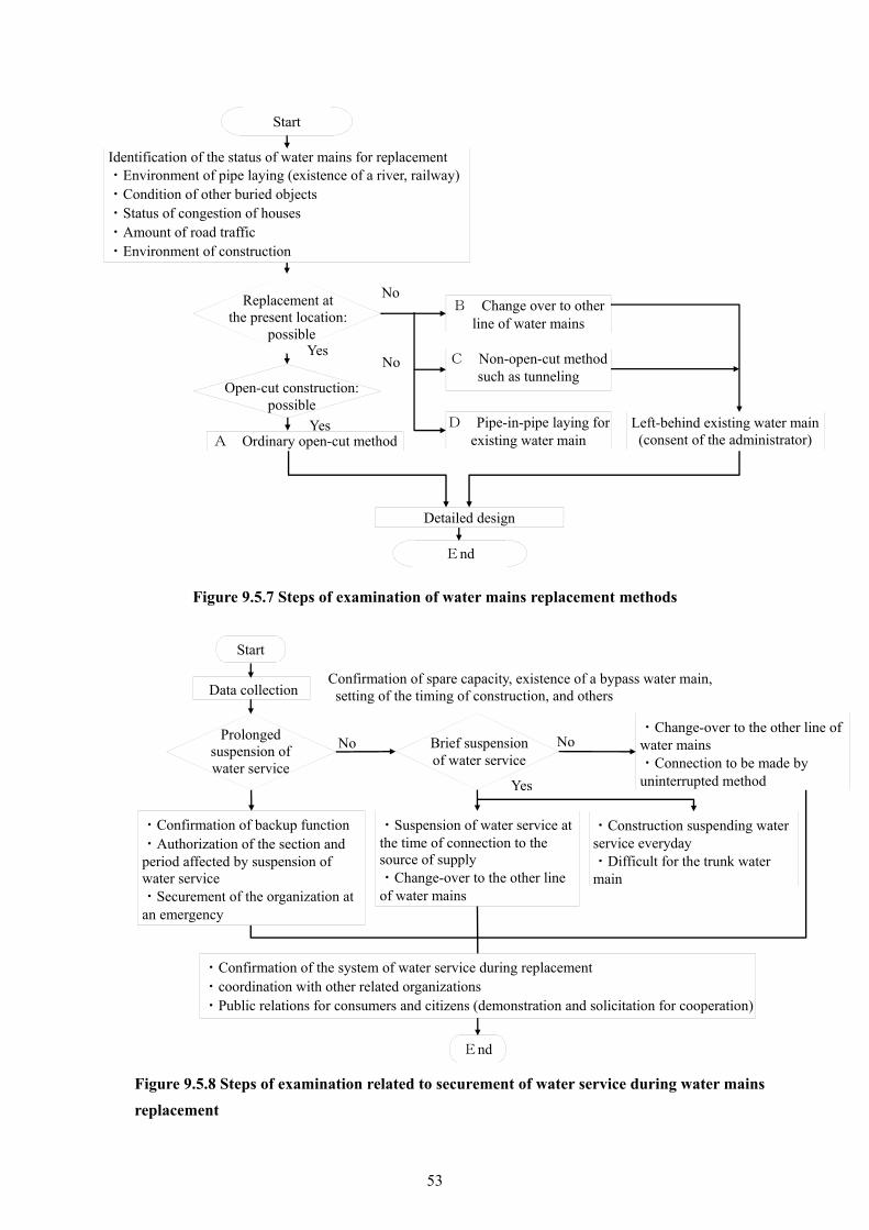
53
Figure 9.5.7 Steps of examination of water mains replacement methods
Figure 9.5.8 Steps of examination related to securement of water service during water mains
replacement
Start
Identification of the status of water mains for replacement ・Environment of pipe laying (existence of a river, railway)・Condition of other buried objects ・Status of congestion of houses ・Amount of road traffic ・Environment of construction
Replacement at
the present location: possible
A Ordinary open-cut method
Open-cut construction: possible
Left-behind existing water main (consent of the administrator)
B Change over to other line of water mains
C Non-open-cut method such as tunneling
D Pipe-in-pipe laying for existing water main
Detailed design
End
No
NoYes
Yes
Start
Data collection
Prolonged
suspension of water service
・Change-over to the other line of water mains ・Connection to be made by uninterrupted method
・Suspension of water service at the time of connection to the source of supply ・Change-over to the other line of water mains
・Confirmation of the system of water service during replacement ・coordination with other related organizations ・Public relations for consumers and citizens (demonstration and solicitation for cooperation)
NoNo
Yes
Brief suspension of water service
・Confirmation of backup function ・Authorization of the section and period affected by suspension of water service ・Securement of the organization at an emergency
・Construction suspending water service everyday ・Difficult for the trunk water main
End
Confirmation of spare capacity, existence of a bypass water main, setting of the timing of construction, and others
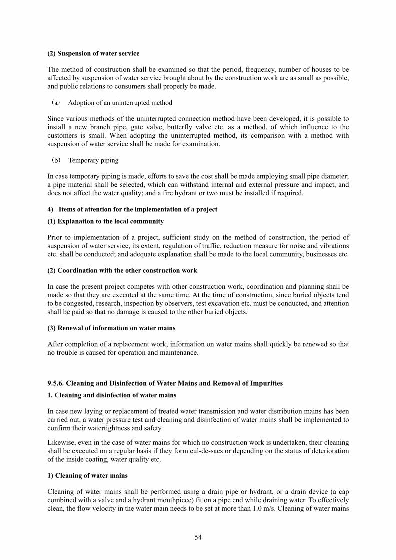
54
(2) Suspension of water service
The method of construction shall be examined so that the period, frequency, number of houses to be affected by suspension of water service brought about by the construction work are as small as possible, and public relations to consumers shall properly be made.
Adoption of an uninterrupted method
Since various methods of the uninterrupted connection method have been developed, it is possible to install a new branch pipe, gate valve, butterfly valve etc. as a method, of which influence to the customers is small. When adopting the uninterrupted method, its comparison with a method with suspension of water service shall be made for examination.
Temporary piping
In case temporary piping is made, efforts to save the cost shall be made employing small pipe diameter; a pipe material shall be selected, which can withstand internal and external pressure and impact, and does not affect the water quality; and a fire hydrant or two must be installed if required.
4) Items of attention for the implementation of a project
(1) Explanation to the local community
Prior to implementation of a project, sufficient study on the method of construction, the period of suspension of water service, its extent, regulation of traffic, reduction measure for noise and vibrations etc. shall be conducted; and adequate explanation shall be made to the local community, businesses etc.
(2) Coordination with the other construction work
In case the present project competes with other construction work, coordination and planning shall be made so that they are executed at the same time. At the time of construction, since buried objects tend to be congested, research, inspection by observers, test excavation etc. must be conducted, and attention shall be paid so that no damage is caused to the other buried objects.
(3) Renewal of information on water mains
After completion of a replacement work, information on water mains shall quickly be renewed so that no trouble is caused for operation and maintenance.
9.5.6. Cleaning and Disinfection of Water Mains and Removal of Impurities
1. Cleaning and disinfection of water mains
In case new laying or replacement of treated water transmission and water distribution mains has been carried out, a water pressure test and cleaning and disinfection of water mains shall be implemented to confirm their watertightness and safety.
Likewise, even in the case of water mains for which no construction work is undertaken, their cleaning shall be executed on a regular basis if they form cul-de-sacs or depending on the status of deterioration of the inside coating, water quality etc.
1) Cleaning of water mains
Cleaning of water mains shall be performed using a drain pipe or hydrant, or a drain device (a cap combined with a valve and a hydrant mouthpiece) fit on a pipe end while draining water. To effectively clean, the flow velocity in the water main needs to be set at more than 1.0 m/s. Cleaning of water mains

55
shall be continued until no turbidity is seen in discharged waste.
As one of methods of water mains cleaning, there also is a method to insert a pig made of special polyurethane, and wash away impurities in the main by water pressure together with the pig.
2) Disinfection of water mains
To disinfect water mains, chlorinated water is injected, while draining water, by a plunger pump etc, from such opening as a hydrant and a corporation tap at the upstream end of the section under operation so that the residual chlorine in the water in the pipe becomes 10 mg/L or so. When the residual chlorine in the drained water becomes 10 mg/L or so, injection of chlorinated water and drain of water are stopped, the water main is left at rest for 24 hours, residual chlorine in the main is tested, and this process shall be repeated until the residual chlorine becomes more than 5 mg/L. When residual chlorine has risen more than 5 mg/L, injection of chlorine water is stopped, the water source is switched to ordinary tap water and water drain shall be resumed.
At the point of time when residual chlorine in drained water decrease to become the same level with tap water, turbidity, odor, pH etc. are tested, and then the water mains are to be put in commission if these values meet the water quality standards.
In case the newly laid water main is connected with an existing water main, and water with 10 mg/L of residual chlorine cannot be introduced for disinfection, the new water main shall be washed with three times volume or more of the inside volume of the main to be fed from the existing main, and the water main shall be put in commission after residual chlorine has become about the same with that of the upstream water main.
In case water containing chlorine is drained, dechlorination of the water with sodium sulfite, sodium thiosulfate etc. is needed to avoid the occurrence of chlorine odor, kill of fish and so forth.
2. Removal of impurities
Such impurities as sand, rust and seal coat tend to deposit in existing water mains. These impurities may travel through the water main and bring about such a trouble as clogging of the strainer of water meters and water service apparatuses. In case deposit or suspension of impurities is observed in the water main, sufficient study shall be conducted based on its cause, type, the past record of impurities, and other experiences so that they shall properly be removed.
1) Types of impurities
Types, property and settling velocity of main impurities are presented on Table 9.5.8

56
Table 9.5.8 Specific gravity and settling velocity of main impurities
Particle diameter Specific gravity Settling velocity mm g/cm mm/s
CL sand for large pipe 4.75~3.36 2.54 283.53 2.36~1.70 2.49 180.50 1.18~0.60 2.38 101.97
CL sand for medium pipe3.36~2.36 2.47 224.20 1.70~1.18 2.42 146.57 1.18~0.60 2.28 110.75
CL sand for small pipe 1.18~0.60 2.05 91.06 0.60~0.30 2.07 68.97
Iron rust 4.75~3.36 2.12 186.85 (particle diameter 5 mm)
2.36~1.70 1.99 147.43 (particle diameter 3~4 mm) - - 87.91 (particle diameter 1 mm)
Iron rust(minute particle) 0.60~030 - 43.54
Coating flakes (seal coat)5 1.1 5.38
3~4 1.1 3.92 2 1.1 3.46
(Source: Report of No. 1 Research Group for Epoch Project 2004: Water Mains)
2) Movements of impurities in water mains
Impurities show different movements in the water main depending on their nature. Iron rust, sand etc., of which specific gravity is relatively large, easily settle on the pipe bottom, and do not move if the velocity of flow is small. On the other hand, seal coat has small specific gravity, and starts to move with flow velocity of higher than 0.1 m/s. Movements of impurities in the water main are given on Table 9.5.9. Also, depositing locations of impurities obtained by experiments which were undertaken by some water utilities are tabulated on Table 9.5.10.
As one of methods to study on the existence, type, status of deposition and movements, there is a method using an endoscope camera inserted in the water main from a hydrant etc. by an uninterrupted method.
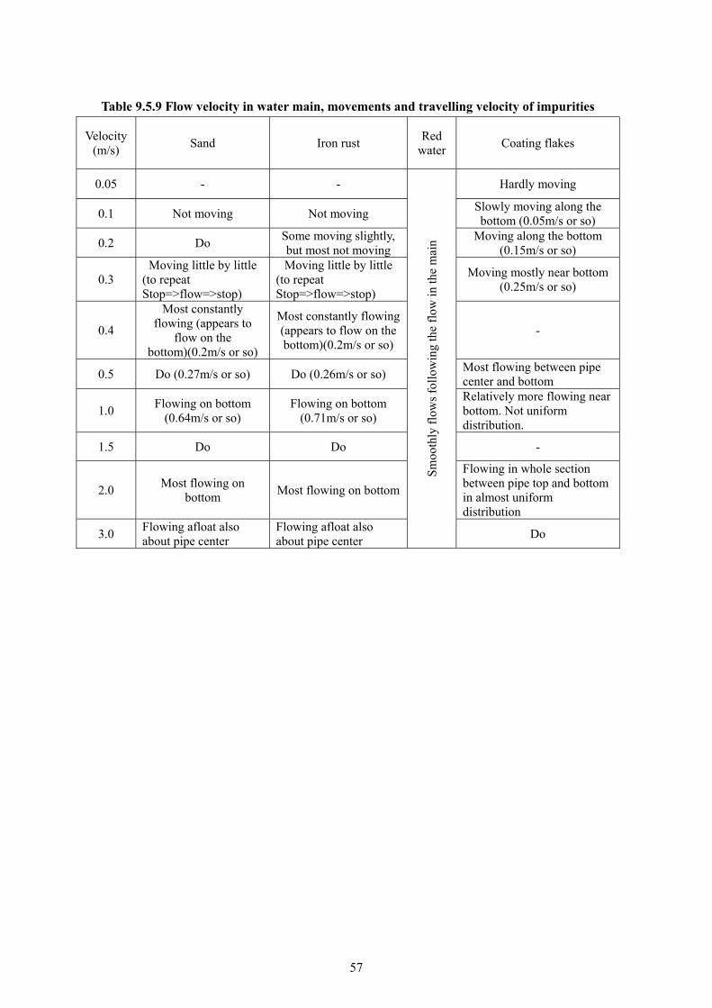
57
Table 9.5.9 Flow velocity in water main, movements and travelling velocity of impurities
Velocity (m/s)
Sand Iron rust Red
waterCoating flakes
0.05 - -
Sm
ooth
ly f
low
s fo
llow
ing
the
flow
in th
e m
ain
Hardly moving
0.1 Not moving Not moving Slowly moving along the bottom (0.05m/s or so)
0.2 Do Some moving slightly, but most not moving
Moving along the bottom (0.15m/s or so)
0.3 Moving little by little
(to repeat Stop=>flow=>stop)
Moving little by little (to repeat Stop=>flow=>stop)
Moving mostly near bottom (0.25m/s or so)
0.4
Most constantly flowing (appears to
flow on the bottom)(0.2m/s or so)
Most constantly flowing (appears to flow on the bottom)(0.2m/s or so)
-
0.5 Do (0.27m/s or so) Do (0.26m/s or so) Most flowing between pipe center and bottom
1.0 Flowing on bottom
(0.64m/s or so) Flowing on bottom
(0.71m/s or so)
Relatively more flowing near bottom. Not uniform distribution.
1.5 Do Do -
2.0 Most flowing on
bottom Most flowing on bottom
Flowing in whole section between pipe top and bottom in almost uniform distribution
3.0 Flowing afloat also about pipe center
Flowing afloat also about pipe center
Do
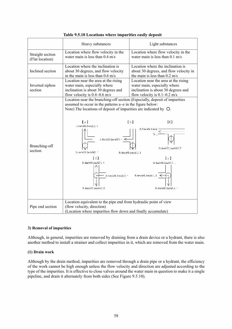
58
Table 9.5.10 Locations where impurities easily deposit
Heavy substances Light substances
Straight section (Flat location)
Location where flow velocity in the water main is less than 0.4 m/s
Location where flow velocity in the water main is less than 0.1 m/s
Inclined section Location where the inclination is about 30 degrees, and flow velocity in the main is less than 0.6 m/s
Location where the inclination is about 30 degrees, and flow velocity in the main is less than 0.2 m/s
Inverted siphon section
Location near the area at the rising water main, especially where inclination is about 30 degrees and flow velocity is 0.4~0.6 m/s
Location near the area at the rising water main, especially where inclination is about 30 degrees and flow velocity is 0.1~0.2 m/s
Branching-off section
Location near the branching-off section (Especially, deposit of impurities assumed to occur in the patterns a~e in the figure below: Note) The locations of deposit of impurities are indicated by ○.
Pipe end section Location equivalent to the pipe end from hydraulic point of view (flow velocity, direction) (Location where impurities flow down and finally accumulate)
3) Removal of impurities
Although, in general, impurities are removed by draining from a drain device or a hydrant, there is also another method to install a strainer and collect impurities in it, which are removed from the water main.
(1) Drain work
Although by the drain method, impurities are removed through a drain pipe or a hydrant, the efficiency of the work cannot be high enough unless the flow velocity and direction are adjusted according to the type of the impurities. It is effective to close valves around the water main in question to make it a single pipeline, and drain it alternately from both sides (See Figure 9.5.10).
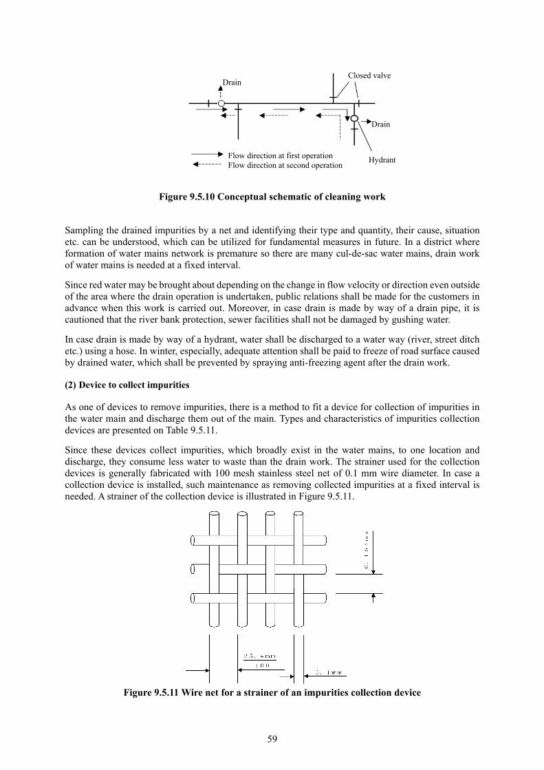
59
Figure 9.5.10 Conceptual schematic of cleaning work
Sampling the drained impurities by a net and identifying their type and quantity, their cause, situation etc. can be understood, which can be utilized for fundamental measures in future. In a district where formation of water mains network is premature so there are many cul-de-sac water mains, drain work of water mains is needed at a fixed interval.
Since red water may be brought about depending on the change in flow velocity or direction even outside of the area where the drain operation is undertaken, public relations shall be made for the customers in advance when this work is carried out. Moreover, in case drain is made by way of a drain pipe, it is cautioned that the river bank protection, sewer facilities shall not be damaged by gushing water.
In case drain is made by way of a hydrant, water shall be discharged to a water way (river, street ditch etc.) using a hose. In winter, especially, adequate attention shall be paid to freeze of road surface caused by drained water, which shall be prevented by spraying anti-freezing agent after the drain work.
(2) Device to collect impurities
As one of devices to remove impurities, there is a method to fit a device for collection of impurities in the water main and discharge them out of the main. Types and characteristics of impurities collection devices are presented on Table 9.5.11.
Since these devices collect impurities, which broadly exist in the water mains, to one location and discharge, they consume less water to waste than the drain work. The strainer used for the collection devices is generally fabricated with 100 mesh stainless steel net of 0.1 mm wire diameter. In case a collection device is installed, such maintenance as removing collected impurities at a fixed interval is needed. A strainer of the collection device is illustrated in Figure 9.5.11.
Figure 9.5.11 Wire net for a strainer of an impurities collection device
DrainClosed valve
Drain
Hydrant Flow direction at first operation Flow direction at second operation

60
Table 9.5.11 Types and characteristics of impurities collection devices
Type Shape Characteristics
Spiral type T
(1) Possible to be used as hydrant
(2) Compact (3) Impurities flowing on pipe
bottom can effectively be discharged when flushing the water main.
T with valve
(1) Possible to be used as hydrant
(2) Compact (3) Impurities flowing on pipe
bottom can effectively be discharged when flushing the water main
(4) Can deal with both directions of flow.
Double pipe type hydrant
(1) Possible to be used as hydrant
(2) Compact (3) Impurities flowing on pipe
bottom can effectively be discharged when flushing the water main
(4) Function to store impurities.
Drain T
(1) Impurities flowing on pipe bottom can effectively be discharged when flushing the water main
Hydrant
(1) Can discharge impurities while using as hydrant
Y-type strainer
(1) Impurities can be collected by the inside of a cylindrical strainer and discharged by draining.
(2) Can only deal with one direction
Special strainer
(1) Impurities can be collected by a strainer and discharged by draining.
(2) Its structure makes it possible to clear clogging of strainer at the same time as draining.
(3) Can deal with both directions of flow.
One direction type Two-way type
61
9.5.7. Prevention and Restoration of Accidents on Water Mains
Accidents on water mains have a risk of bringing about not only sudden suspension or reduction of water service and turbid water but such a collateral disaster as cave-in of a road, which entrains traffic obstacles, and inundation of houses, so its social impact is large. Therefore, a prevention plan shall be established, and efforts shall be made to prevent accidents on water mains through regular implementation of their inspection and maintenance, improvement of aged water mains and so forth. A system to quickly do restoration shall be established as preparation for an accident just in case.
1. Prevention plan
1) Inspection and improvement of water mains
Water mains shall at a fixed interval be inspected, and repair defects without delay when they are found. To this end, signs clearly indicating locations of water mains shall be placed, and registers and drawings of ancillary facilities shall be provided.
(1) Installation of signs for water mains
The sign board for water mains shall bear such necessary items as pipe diameter, depth of burial, ground elevation etc.
Also as to valves, air-valves etc., their locations indicated by offsetting, nominal diameters, direction of opening and closing, the number of rotations, aperture, the history of operation and so on shall be recorded in a valve register. Additionally, a nameplate shall be fit on the underside of the manhole cover or in the valve box so that such information as the above can be identified at site.
(2) Clear indication of water mains
To prevent an accident to be caused by misidentification of the water main with a buried object of other enterprise at the time of excavation of a road, the name of the object, the name of its administrator, its date of burial etc. of the occupying object under the road shall clearly be inscribed on a durable tape which is stuck on the objects.
Likewise, in case an existing water main with no inscribed identification is exposed at the time of construction work of other enterprise, a tape with clear inscription shall be stuck around the water main.
For water mains of 350 mm diameter or smaller, a tape to be stuck along the pipe top in addition to the bellyband type tape can make identification of the water main easy at the time of excavation. Furthermore, there is a method to place a sheet with clear inscription 30 cm above the top of the water main.
(3) Tour of inspection of water mains
To prevent an accident and early find a defective location, the frequency of patrol and inspection in consideration of the priority, magnitude of risk etc. shall be determined; and inspection shall be carried out at a fixed interval so that, if a defect is found, it shall quickly be repaired. Standards of inspection in accordance with the magnitude of an earthquake etc. shall be established in the case of an earthquake and so on. The outcome of patrol and inspection shall be recorded and classified in a record book so that the information can always be grasped.
During inspection, attention shall be paid to cave-in of the road, cracking, uneven subsidence etc.; and the cause shall be studied by means of acoustic sounding or excavation.
Adequate watching shall be practiced on freeze of road surface caused by water leakage, a rattling iron manhole lid and difference in level, improper management of the remain of water service construction work etc.
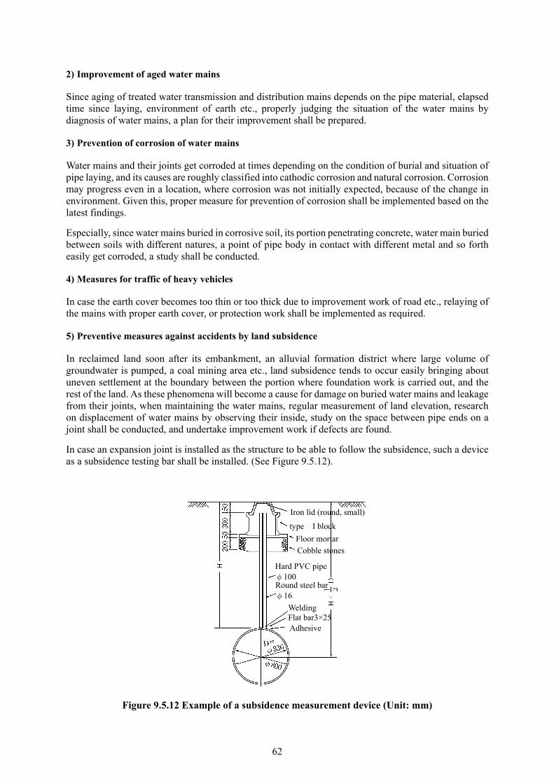
62
2) Improvement of aged water mains
Since aging of treated water transmission and distribution mains depends on the pipe material, elapsed time since laying, environment of earth etc., properly judging the situation of the water mains by diagnosis of water mains, a plan for their improvement shall be prepared.
3) Prevention of corrosion of water mains
Water mains and their joints get corroded at times depending on the condition of burial and situation of pipe laying, and its causes are roughly classified into cathodic corrosion and natural corrosion. Corrosion may progress even in a location, where corrosion was not initially expected, because of the change in environment. Given this, proper measure for prevention of corrosion shall be implemented based on the latest findings.
Especially, since water mains buried in corrosive soil, its portion penetrating concrete, water main buried between soils with different natures, a point of pipe body in contact with different metal and so forth easily get corroded, a study shall be conducted.
4) Measures for traffic of heavy vehicles
In case the earth cover becomes too thin or too thick due to improvement work of road etc., relaying of the mains with proper earth cover, or protection work shall be implemented as required.
5) Preventive measures against accidents by land subsidence
In reclaimed land soon after its embankment, an alluvial formation district where large volume of groundwater is pumped, a coal mining area etc., land subsidence tends to occur easily bringing about uneven settlement at the boundary between the portion where foundation work is carried out, and the rest of the land. As these phenomena will become a cause for damage on buried water mains and leakage from their joints, when maintaining the water mains, regular measurement of land elevation, research on displacement of water mains by observing their inside, study on the space between pipe ends on a joint shall be conducted, and undertake improvement work if defects are found.
In case an expansion joint is installed as the structure to be able to follow the subsidence, such a device as a subsidence testing bar shall be installed. (See Figure 9.5.12).
Figure 9.5.12 Example of a subsidence measurement device (Unit: mm)
type I block
Iron lid (round, small)
Cobble stones
Floor mortar
Round steel bar φ16
Hard PVC pipeφ100
Adhesive Flat bar3×25 Welding

63
6) Prevention of leakage and freezing
To prevent accidents caused by water leakage and freezing, a tour of inspection shall be enforced. If freeze is found, a freeze-resolving agent shall be sprayed and a security device shall be installed
7) Measures to prevent accidents related to construction
In case the excavated trench is inundated during construction, or the groundwater level is high even after backfilling, caution shall be paid since empty pipes may at times surface.
In case excavation is made close to an existing water main, construction shall be carried out after protection measure is provided so that the water main does not move by water pressure. Especially, sufficient reinforcement shall be made at the backside of special fittings, pipe end, valve, plug and cap.
When installing a plug or cap, air in the water main shall sufficiently be exhausted; and when removing the plug or cap, it shall be confirmed that pressure is not remaining in the water main, and no work shall be undertaken in front of the plug or cap.
8) Preventive measures against accidents of ancillary facilities
Air valves shall always be inspected and maintained so that they can normally inhale and exhaust air. If air piles up in the water main, water flow is impeded, or it at times induces an accident of water main’s burst.
What’s more, the iron lid shall be set at level with the surrounding road surface to prevent its rattling or leaping-up.
Additionally, operation of a valve shall carefully be made since forceful operation may bring about a failure of the valve. As rubber is used for water seal of the soft-seal gate valve, no definite feeling such as one in the case of the ordinary gate valve may be obtained at the time of complete closure. Therefore, it is warned that excessive force shall not be rendered in operation so that the valve is not damaged.
9) Preventive measures against cross connection
To prevent an accident of cross connection with a water main for the industrial water supply etc., identification shall be made with a tape etc. on the outside of the main with clear inscription. In case identification with a tape cannot be made clearly, confirmation shall be made by measuring the concentration of residual chlorine, water temperature, water quality etc.
2. Preventive measures against accidents caused by other construction work
In case construction work by other enterprise is carried out where treated water transmission and distribution mains have been laid, consultation shall be made with the owner of the work and the contractor on necessary security measures to prevent the influence or damage on the existing water mains. In addition, prior to the work, site observation shall be conducted to confirm the safety of the construction method, and proper instruction shall be given if something unsatisfactory is found.
1) Preliminary survey and consultation
Prior to construction, the owner of the work or its contractor shall be obliged to implement a site survey, test excavation etc. based on as-built drawings, and confirm the pipe material, diameter, location, depth of burial etc. of the existing water mains.
2) Extent of influence
The extent of influence of excavation is 45 degrees from the excavation floor as the standard extent, which shall be adjusted depending on soil quality. In the case of the pipe-thrusting method and the shield

64
method, it is common to determine the height of loosened soil using the Terzaghi's formula based on data of soil surveys etc.
3) Security measures
In case the existing water mains are in the extent of influence or exposed, consultation about security measures shall be made, and a security measure suitable for the situation shall be provided.
Especially, in the case of water mains with such a weak material as aged pipe, replacement of water mains and so forth shall be implemented by means of changing the pipe material. Likewise, consultation shall be made on execution of security measures, allocation of costs, monitoring organization of construction sites, the method of calling for observers of construction work, the method of communications at a time of emergency etc. Main security measures are presented on Table 9.5.14..
Table 9.5.14 Main security measures 1. Work of safety measure Suspension device To hang facilities with wire etc. Supporting cradle To support facilities with steel materials etc. Stabilizing device To make preventive measures against a lateral rolling
suppresser, a escape arresting device and so on by means of fixing facilities with steel materials etc.
Lateral rolling suppresser Escape arresting device 2. Other security measures than 1. above Bypassing To move facilities avoiding the influence Temporary piping To temporarily move facilities out of influence and restore
afterwards Change to another pipe material
To change water mains to ones with stronger pipe material to secure safety
Temporary suspension of use During construction, to suspend the use of facilities by stopping water service and so on
Installation of expansion-flexible pipe
To install an expansion-flexible pipe and absorb the effect of displacement
Reinforcement of joints To reinforce pipe joints with special separate gland followers, leak prevention devices etc.
Installation of emergency valves
To install gate valves as preparation for emergency suspension of water service
Repair of outside coating To repair damaged outside coating Installation of subsidence gauge
To install subsidence gauges to confirm the influence to facilities
4) Space between water supply facilities and other structure
More than 30 to 50 cm of space depending on the size of the water main shall be secured between existing water mains and other buried objects from the viewpoints of securement of safety and future maintenance. Space of less than the above value makes branching of a service pipe, or repair of the water main difficult. Just in case they come in direct contact with other objects, there is a fear that the water main gets broken.
In case a structure is built right underneath the water main, it is concerned that uneven subsidence may occur somewhat apart from the structure even if certain space is maintained. As such, expansion joints, which can absorb the bearing force on the water main, or a protection block etc. shall be installed.
3. Items of attention at the time of site observation
Site observation shall be conducted at the request of the contractor in accordance with the purport of the consultation in advance. The observer shall confirm the progress of the work, and instruct contractor to properly improve the matters related to the obstacles related to the existing water mains.
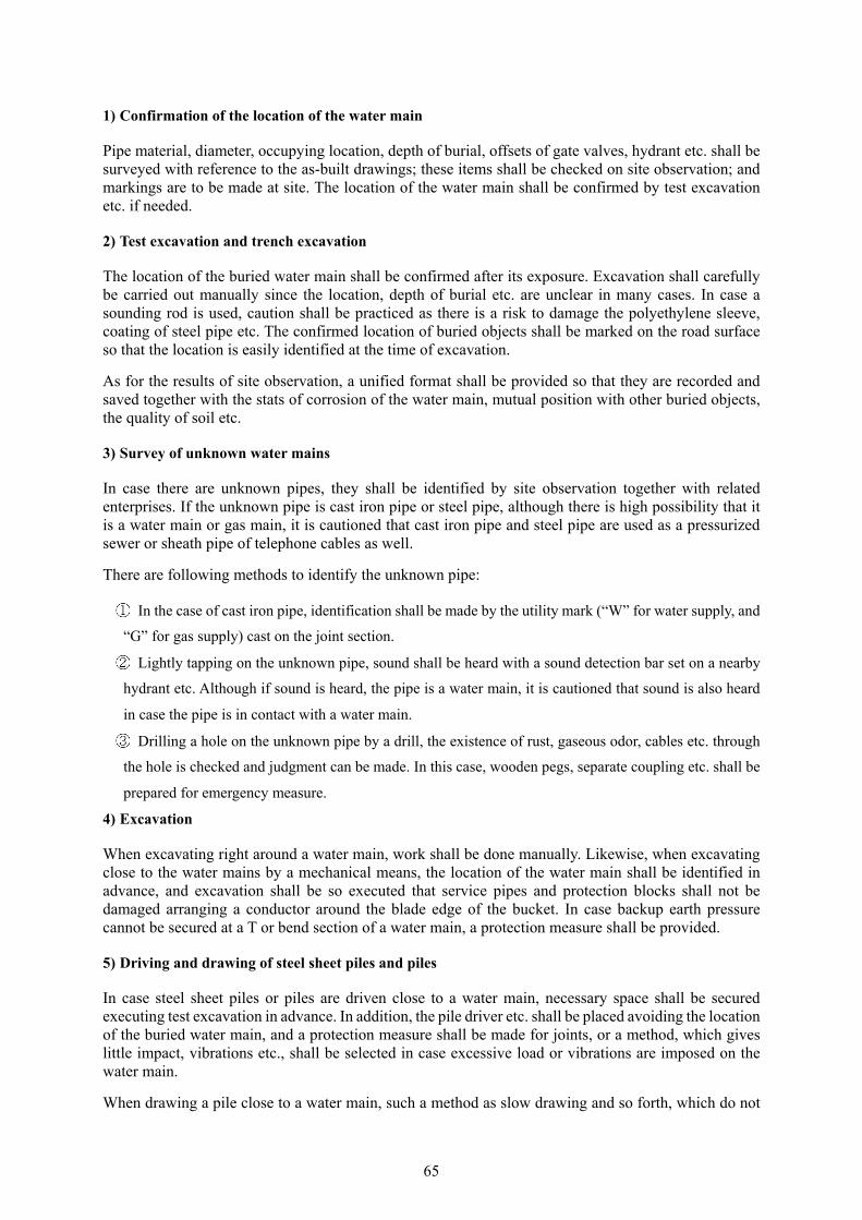
65
1) Confirmation of the location of the water main
Pipe material, diameter, occupying location, depth of burial, offsets of gate valves, hydrant etc. shall be surveyed with reference to the as-built drawings; these items shall be checked on site observation; and markings are to be made at site. The location of the water main shall be confirmed by test excavation etc. if needed.
2) Test excavation and trench excavation
The location of the buried water main shall be confirmed after its exposure. Excavation shall carefully be carried out manually since the location, depth of burial etc. are unclear in many cases. In case a sounding rod is used, caution shall be practiced as there is a risk to damage the polyethylene sleeve, coating of steel pipe etc. The confirmed location of buried objects shall be marked on the road surface so that the location is easily identified at the time of excavation.
As for the results of site observation, a unified format shall be provided so that they are recorded and saved together with the stats of corrosion of the water main, mutual position with other buried objects, the quality of soil etc.
3) Survey of unknown water mains
In case there are unknown pipes, they shall be identified by site observation together with related enterprises. If the unknown pipe is cast iron pipe or steel pipe, although there is high possibility that it is a water main or gas main, it is cautioned that cast iron pipe and steel pipe are used as a pressurized sewer or sheath pipe of telephone cables as well.
There are following methods to identify the unknown pipe:
In the case of cast iron pipe, identification shall be made by the utility mark (“W” for water supply, and
“G” for gas supply) cast on the joint section.
Lightly tapping on the unknown pipe, sound shall be heard with a sound detection bar set on a nearby
hydrant etc. Although if sound is heard, the pipe is a water main, it is cautioned that sound is also heard
in case the pipe is in contact with a water main.
Drilling a hole on the unknown pipe by a drill, the existence of rust, gaseous odor, cables etc. through
the hole is checked and judgment can be made. In this case, wooden pegs, separate coupling etc. shall be
prepared for emergency measure.
4) Excavation
When excavating right around a water main, work shall be done manually. Likewise, when excavating close to the water mains by a mechanical means, the location of the water main shall be identified in advance, and excavation shall be so executed that service pipes and protection blocks shall not be damaged arranging a conductor around the blade edge of the bucket. In case backup earth pressure cannot be secured at a T or bend section of a water main, a protection measure shall be provided.
5) Driving and drawing of steel sheet piles and piles
In case steel sheet piles or piles are driven close to a water main, necessary space shall be secured executing test excavation in advance. In addition, the pile driver etc. shall be placed avoiding the location of the buried water main, and a protection measure shall be made for joints, or a method, which gives little impact, vibrations etc., shall be selected in case excessive load or vibrations are imposed on the water main.
When drawing a pile close to a water main, such a method as slow drawing and so forth, which do not
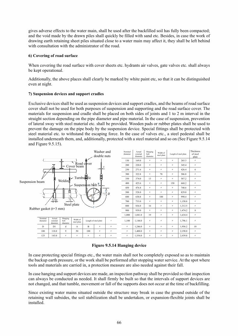
66
gives adverse effects to the water main, shall be used after the backfilled soil has fully been compacted; and the void made by the drawn piles shall quickly be filled with sand etc. Besides, in case the work of drawing earth retaining sheet piles situated close to a water main may affect it, they shall be left behind with consultation with the administrator of the road.
6) Covering of road surface
When covering the road surface with cover sheets etc. hydrants air valves, gate valves etc. shall always be kept operational.
Additionally, the above places shall clearly be marked by white paint etc, so that it can be distinguished even at night.
7) Suspension devices and support cradles
Exclusive devices shall be used as suspension devices and support cradles, and the beams of road surface cover shall not be used for both purposes of suspension and supporting and the road surface cover. The materials for suspension and cradle shall be placed on both sides of joints and 1 to 2 m interval in the straight section depending on the pipe diameter and pipe material. In the case of suspension, prevention of lateral sway with steel material etc. shall be provided. Wooden pads or rubber plates shall be used to prevent the damage on the pipe body by the suspension device. Special fittings shall be protected with steel material etc. to withstand the escaping force. In the case of valves etc., a steel pedestal shall be installed underneath them, and, additionally, protected with a steel material and so on (See Figure 9.5.14 and Figure 9.5.15).
Nominal diameter
Actual external diameter
Hanging bolt diameter
Width of steel plate
Length of steel plate Thickness
of steel plate
150 169.0 〃 〃 〃 265.3 〃
200 220.0 〃 〃 〃 345.4 〃
250 271.6 〃 〃 〃 426.4 6
300 322.8 〃 70 〃 506.8 〃
350 374.0 13 〃 〃 587.2 〃
400 425.6 〃 〃 150 668.2 〃
450 476.8 〃 〃 〃 748.6 〃
500 528.0 〃 〃 〃 829.0 〃
600 630.8 〃 100 〃 990.4 〃
700 733.0 〃 〃 〃 1,150.8 〃
800 836.0 16 〃 〃 1,312.5 〃
900 939.0 〃 〃 〃 1,474.2 8
1,000 1,041.0 19 〃 〃 1,634.4 〃
Nominal diameter
Actual external diameter
Hanging bolt diameter
Width of steel plate
Length of steel plate 〃 1,100 1,144.0 〃 〃 〃 1,796.1 〃
D D1 d A B 〃 〃 〃 1,246.0 〃 〃 〃 1,956.2 10
100 118.0 9 50 100 〃 〃 〃 1,400.0 〃 〃 〃 2,198.0 〃
125 143.0 〃 〃 〃 〃 〃 〃 1,554.0 〃 〃 〃 2,439.8 〃
Figure 9.5.14 Hanging device
In case protecting special fittings etc., the water main shall not be completely exposed so as to maintain the backup earth pressure, or the work shall be performed after stopping water service. At the spot where tools and materials are carried in, a protection measure are also needed against their fall.
In case hanging and support devices are made, an inspection pathway shall be provided so that inspection can always be conducted as needed. It shall firmly be built so that the intervals of support devices are not changed, and that tumble, movement or fall of the supports does not occur at the time of backfilling.
Since existing water mains situated outside the structure may break in case the ground outside of the retaining wall subsides, the soil stabilization shall be undertaken, or expansion-flexible joints shall be installed.
Road cover Cover beam
Rubber gasket (t=3 mm)
Suspension beam Welding Turnbuckle
Suspension bolt
Washer and double nuts
Steel plate

67
(Unit:mm)
Diameter Escaping
force A B C(Per each strip)
100 0.5 t L-65×65×6 PL-4.5×50 Bolt φ16×4
150 1.0 〃 〃 〃
200 1.9 〃 〃 〃
300 4.3 -6×125×65 〃 6×70 〃 φ16×6
400 7.7 〃 〃 〃
500 12.0 〃 〃 〃
600 17.3 -9×150×75 〃 9×100 〃 φ19× Note) 1 This drawing shows the method of protection for a 45 degrees bend. The same method shall apply to a bend of other degrees, so permission of the authority shall be asked submitting drawings and a statement of computation.
700 23.4 〃 〃 〃
800 30.8 〃 〃 〃
900 38.9 -10×200×90 〃 φ22×8 2.In the case of the bell-and-spigot joint, leak-proof devices shall be fit prior to the present construction work. 1,000 48.0 〃 〃 〃
1,100 58.5 〃 〃 〃 3.As to the D material, a material, which is adequately resistant to the escaping force, shall be used. 1,200 69.4 -11×250×90 〃 12×100 〃 φ22×10
1,350 87.5 〃 〃 〃 4.As escaping force is always acting by water pressure, consultation with the authority shall be conducted prior to the work.
1,500 108.0 〃 〃 〃
Figure 9.5.15 Protection of bends
8) Backfilling
Before backfilling, damages on the pipe body and the polyethylene sleeve shall be checked, and they shall be repaired if there are damages. Backfilling around water mains shall firmly be carried out using sand or good soil providing sound protection of the mains, and the soil shall fully be compacted so that no subsidence would occur after backfilling.
Temporary protection work shall be removed after backfilling when the ground is stabilized, and such a measure as soil improvement shall be undertaken in accordance with the situation. Furthermore, in case the earth cover of water mains is shallow or instruction is given by the administrator of the road, a distinct identification sheet shall be placed depending on the situation.
9) Restoration of road surface
Caution shall be practiced so that the tamping machine does not damage or move iron lids etc. Likewise, in case there are a gap in level with the road surface, displacement, inclination, burial etc., adjustment of the gap or reinstallation of the lid shall quickly be carried out.
Suspension beam
Channel A
Bolt C
L for diameter of less than 200
Strip B
Rubber gasket Thickness

68
10) Chemical injection
In case chemical injection is undertaken in the vicinity of water mains, it shall be carried out after confirming the location and depth of burial by test excavation etc., and exposing the water main. In the event the water main cannot be exposed, the injection shall be implemented confirming the safety with installation of a casing pipe or guide pipe. In addition, such changes as subsidence or rise of ground shall be monitored so that the water main is not moved by the injection, and, if an anomaly is found, injection shall be stopped and consultation shall be made again.
4. Restoration from an accident
1) Establishment of a restoration system
To deal with an unexpected accident, the present activities shall be defined for a manning plan, water management after suspension and resumption of water service, a restoration plan, restoration work, measures against turbid water, public relations, emergency water service, study on the cause, emergent measures for victims, study on damage, compensation for the damage and so forth. Secondly, a mutual communications system between these activities and a system of restoration shall be established.
At an accident, which causes big damage, and which affects a large area with suspension and reduction of water service, and turbid water, an emergency headquarters shall be established at site so that measures against the accident are carried out under the direction of a director.
(1) Manning system
Preparing for an accident which occurs in extra hours, work shift for the night and a holiday shall be established. Specifically speaking, a manning plan, which sets up the designation of restoration staff, steps of arrangement for communications, the place for muster of the staff etc. shall be established so that they can immediately be deployed.
(2) System of assistance and support
There is a case in which assistance of pipe laying contractors etc. is required depending on the type, scale and details of the accident. To secure an organization for acquisition of assistance for materials, manpower etc. at an emergency, a system needs to be established in advance on steps for designation of the contractor, the method of contract and so on at the time of emergency.
(3) System of communications
As preparation for an unexpected accident, a method of contact to concerned parties and incumbent officers for the task shall be set up for the business hours and each extra hour. If the number of contacts is large, in case there is a system of simultaneous announcement is provided, the number of announcement can be small so no one can be missed.
Besides, assuming that ordinary telephoning cannot be used due to congestion, installation of an exclusive telephone network or a radio communication system shall also be considered.
(4) Systems of public relations and emergency water service
In the case of an unexpected accident, the site shall immediately be visited to identify its details. The cause of the accident, estimated duration of suspension of water service, the area where water service is suspended, reduced or affected by turbid water, and other necessary matters shall be broadcast by a loudspeaker van or bullhorn, and directly informed to schools, hospitals, large water users, and the fire department by telephone etc. In the event of a large scale accident, when a report is made through such media as newspapers, radio, TV etc., an officer incumbent for public relations shall be designated so that unification of public relations is maintained.
69
Furthermore, for smooth water service, vehicles to be used for emergency water service shall be secured at normal times, and water tanks, polyethylene containers etc. shall cleanly be stored.
(5) System of initial activities
When receiving a report of an accident, the site shall be hurriedly visited to know the status of the accident; installation of safety facilities, drainage etc. shall be conducted; and repair work shall immediately be set out. In the case of a large accident with inundation of road surface and houses, water service shall urgently be stopped while contacting related organizations by mobile phone, radio etc. to do public relations, and the damage of the accident shall be studied. Since, if misjudgment is made for initial activities, heavy collateral damage may be induced, special attention shall be paid.
(6) Stockpiling of materials and equipment for restoration work
Since there are so many types of materials and equipment used for treated water transmission and distribution mains, and it is difficult to store all of them, their mutual possession between neighboring cities is also needed. However, since the frequency of the use of such materials for emergency applications as separate couplings etc. is large, they shall be stocked in a quantity in accordance with the pipe material, diameter and length of the treated water transmission and distribution mains.
As rubber rings, gaskets etc. get deteriorated or deformed by direct sunlight, attention shall be paid for their handling.
(7) Drills and training
Since speedy actions are indispensable at an unexpected accident, drills and training shall regularly be conducted.
2) Restoration work
(1) Preliminary communications
Prior to restoration work, communications with the administrator of the road and the police department shall be made; safety devices shall be set up to secure the safety of residents in the neighboring community and general traffic. In case water service is suspended, notification shall be made to such a related organization as the fire department.
What’s more, if other buried object is exposed or situated close to the water main, an observer shall be requested communicating with the respective administrator of the object to have their instructions.
(2) Restoration work in general
Understanding the details of an accident, a restoration plan shall quickly be made so as to speedily and soundly carry out the work.
Moreover, for prevention of recurrence of the accident, reinforcement or replacement of not only the damaged section of the water main but the sections on both sides shall be considered.
(3) Restoration
Although the method of restoration is determined depending on the status of damage, pipe material, location, urgency etc. of the water main, cutting, jointing etc. of the water main shall firmly be undertaken; expansion joints, valves etc. shall as well be installed according to the situation; and backfilling shall carefully be carried out after restoration.
Cutting of the water main shall be executed carefully examining whether or not such damaged part as a crack is left behind. In case it is expected that a gas main is exposed in the excavated trench, an observer of the gas company shall be requested; and if there is a risk of gas leakage, caution shall be made about
70
the use of welding machine, cutter and other tools, which generate heat. Adequate attention shall also be practiced to other buried objects, and proper safety measures shall be provided.
(4) Restoration of leakage from pipe joints
The method of repairing leakage from pipe joints differs depending on the type of the joint and magnitude of leakage. Leakage from a bell-and-spigot joint shall be executed by recalking and a leak-preventive device. Leakage from a mechanical joint shall be treated by retightening of bolts and so forth. In case leakage does not stop, or quantity of leaking water is large, repair shall be undertaken after stopping water service.
Nonetheless, in case water service cannot be stopped, or the influence of suspension of water service is large, repair shall be carried out by means of a non-suspension method using a leak repair device for joints.
(5) Items of attention for construction
Earth retaining
In case water is gushing from a water main, sheet piles shall firmly be driven so as to withstand the force of water. Especially, in the case of loose soil, driving of sheet piles shall carefully and soundly be executed so that safety of the workers is warranted.
Dewatering
Since the work of dewatering the most severely influences the construction schedule, the volume of water inflow inside the trench, and quantity of water in the water main within the range of water service suspension shall be estimated, and a drainage pump with sufficient spare capacity shall be installed. In addition, standby units of pumps shall be provided in consideration of failure of a pump and reduction in its efficiency.
Protection of water mains
Protection of special fittings shall firmly be made so that the pipe does not get out of the joint by water pressure after restart of water service. Such a measure as leaving the retaining beam in place, protection by steel material, fixing of anti-escape devices etc. shall be implemented as required.
Suspension and resumption of water service
In respect to the work of suspension of water service, in case the iron lid is opened at a location which is inundated, sufficient care shall be practiced as there is a risk that workers may be drawn in the box by the flow of water. Secondly, prior to the resumption of water service, it shall be confirmed that protection measures in the work site have been completed.
9.5.8. Leakage prevention
1. Plan for prevention of leakage
1) Setup of the goal
To effectively prevent leakage from distribution mains etc., a plan for prevention of leakage shall be established and then executed based on a basic study on the analysis of the volume of distributed water, identification of water pressure and the volume of leakage etc.
As to the objective ratio of leakage and the design year to be achieved, the present status of water source capacity and water demand of the respective water utilities and the economic benefits of the plan shall
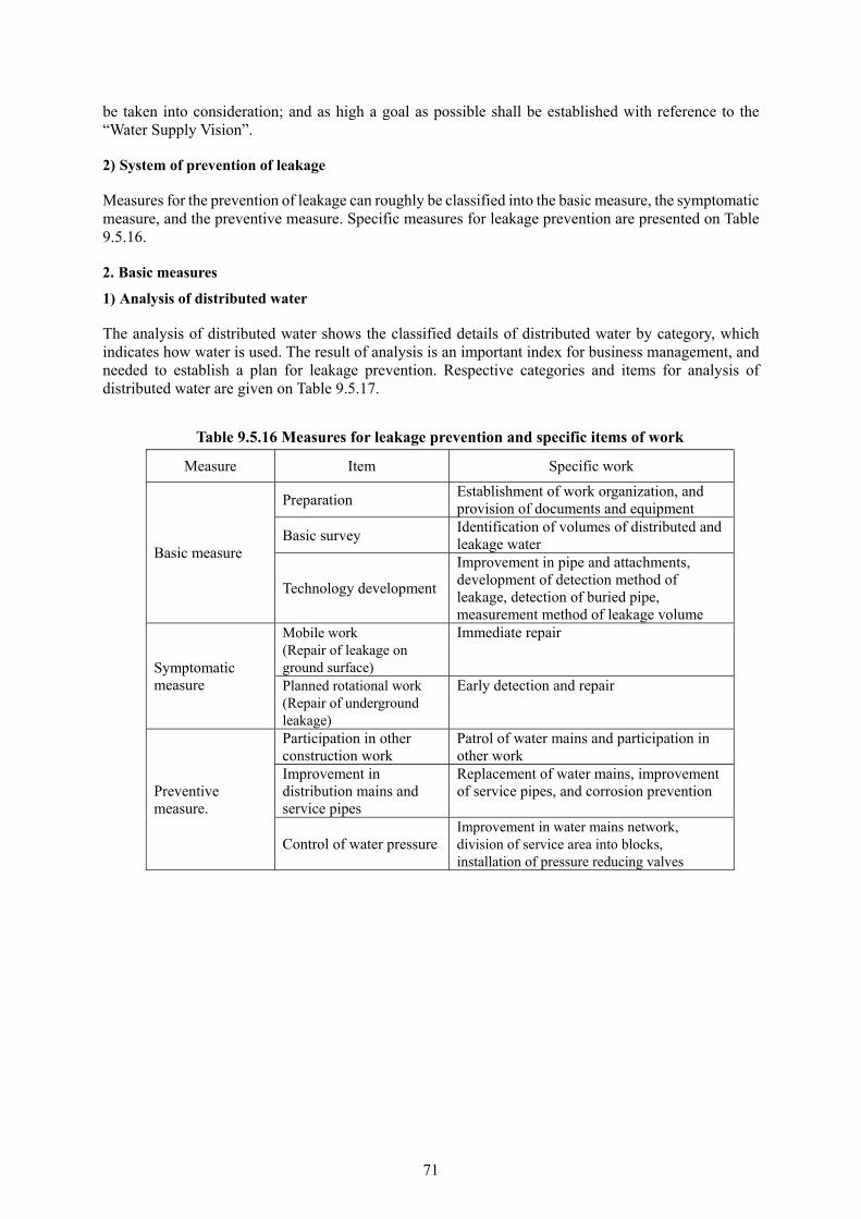
71
be taken into consideration; and as high a goal as possible shall be established with reference to the “Water Supply Vision”.
2) System of prevention of leakage
Measures for the prevention of leakage can roughly be classified into the basic measure, the symptomatic measure, and the preventive measure. Specific measures for leakage prevention are presented on Table 9.5.16.
2. Basic measures
1) Analysis of distributed water
The analysis of distributed water shows the classified details of distributed water by category, which indicates how water is used. The result of analysis is an important index for business management, and needed to establish a plan for leakage prevention. Respective categories and items for analysis of distributed water are given on Table 9.5.17.
Table 9.5.16 Measures for leakage prevention and specific items of work
Measure Item Specific work
Basic measure
Preparation Establishment of work organization, and provision of documents and equipment
Basic survey Identification of volumes of distributed and leakage water
Technology development
Improvement in pipe and attachments, development of detection method of leakage, detection of buried pipe, measurement method of leakage volume
Symptomatic measure
Mobile work (Repair of leakage on ground surface)
Immediate repair
Planned rotational work (Repair of underground leakage)
Early detection and repair
Preventive measure.
Participation in other construction work
Patrol of water mains and participation in other work
Improvement in distribution mains and service pipes
Replacement of water mains, improvement of service pipes, and corrosion prevention
Control of water pressureImprovement in water mains network, division of service area into blocks, installation of pressure reducing valves
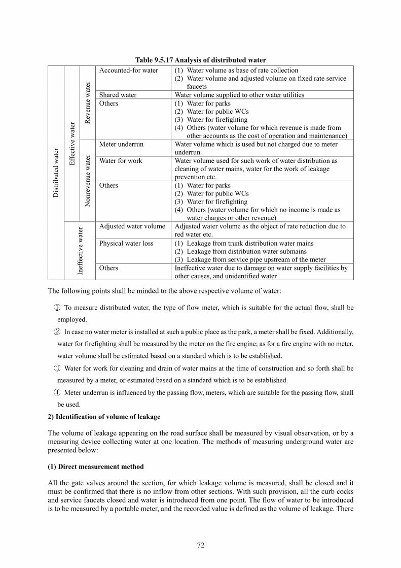
72
Table 9.5.17 Analysis of distributed water D
istr
ibut
ed w
ater
Eff
ectiv
e w
ater
Rev
enue
wat
er
Accounted-for water (1) Water volume as base of rate collection (2) Water volume and adjusted volume on fixed rate service
faucets Shared water Water volume supplied to other water utilities Others (1) Water for parks
(2) Water for public WCs (3) Water for firefighting (4) Others (water volume for which revenue is made from
other accounts as the cost of operation and maintenance)
Non
reve
nue
wat
er
Meter underrun Water volume which is used but not charged due to meter underrun
Water for work Water volume used for such work of water distribution as cleaning of water mains, water for the work of leakage prevention etc.
Others (1) Water for parks (2) Water for public WCs (3) Water for firefighting (4) Others (water volume for which no income is made as
water charges or other revenue)
Inef
fect
ive
wat
er Adjusted water volume Adjusted water volume as the object of rate reduction due to
red water etc. Physical water loss (1) Leakage from trunk distribution water mains
(2) Leakage from distribution water submains (3) Leakage from service pipe upstream of the meter
Others Ineffective water due to damage on water supply facilities by other causes, and unidentified water
The following points shall be minded to the above respective volume of water:
To measure distributed water, the type of flow meter, which is suitable for the actual flow, shall be
employed.
In case no water meter is installed at such a public place as the park, a meter shall be fixed. Additionally,
water for firefighting shall be measured by the meter on the fire engine; as for a fire engine with no meter,
water volume shall be estimated based on a standard which is to be established.
Water for work for cleaning and drain of water mains at the time of construction and so forth shall be
measured by a meter, or estimated based on a standard which is to be established.
Meter underrun is influenced by the passing flow, meters, which are suitable for the passing flow, shall
be used.
2) Identification of volume of leakage
The volume of leakage appearing on the road surface shall be measured by visual observation, or by a measuring device collecting water at one location. The methods of measuring underground water are presented below:
(1) Direct measurement method
All the gate valves around the section, for which leakage volume is measured, shall be closed and it must be confirmed that there is no inflow from other sections. With such provision, all the curb cocks and service faucets closed and water is introduced from one point. The flow of water to be introduced is to be measured by a portable meter, and the recorded value is defined as the volume of leakage. There

73
are two variations in this method.
Circulation method
In this method, the entire service area is the object of measurement, and each divided section is measured in succession, and the results are summed up to become the total leakage volume, which is the most accurate method.
Sampling method
This is a method to select sample model sections from the entire service area, and measure the volume of leakage in such sections; and estimate the volume of leakage for the entire area from the result. In this case, there will be a large error unless appropriate sections are selected. The total length of water mains in the model sections to be measured shall be 3 to 5 percent of the total length of water mains in the service area.
(2) Indirect measurement method
In the indirect measurement method, measurement is carried out by the minimum night flow gauging method. It is a method to measure the volume of leakage with attention to the fact that certain period of time with no water demand (blank time) occurs at midnight; and measurement is made with the curb cock and service faucet at each house are kept open. However, in case inflow to receiving cisterns and continued night use exist, such volume shall in advance be identified and deducted, or such uses shall be restricted. Measurement shall be made by a self-recording flow meter, and the minimum flow is defined as the volume of leakage. This method can apply to a section with 500 customers or so at the maximum (2.5 km to 3.0 km in terms of the length of water mains). As the method of measurement, there are the circulation method and the sampling method. A schematic of the minimum flow measurement methods is shown in Figure 9.5.16.
Figure 9.5.16 Schematic of the minimum flow measurement method
Recorder
【Flow meter for the section】
Distribution mains
Flow meter for the section
Length of distribution mains: approx. 2.5 km【Schematic of the study section】
Water leakage
Flo
w
Time 【Water use chart】
Flow
House C
House B
House ABlank time
Time 【Principle of blank time theory】
Minimum flow

74
(3) Estimation method by analysis of volume of distributed water
In this method, the volume of leakage is estimated based on the difference between the volume of distributed water and the effective water volume, and, in other word, the volume of leakage water is figured out as the balance of the integrated sum of the flow meter for measurement of distributed water and the volume of effective water, water volume for rate adjustment etc.
It is an effective method if the respective volumes to be used for the analysis of distributed water are obtained in high accuracy.
(4) Recovery of water leakage
After repair of leakage, new leaks occur because water mains undergo an earthquake, ground subsidence, corrosion, traffic loads, influence of neighboring construction work etc. This phenomenon is called “Recovery phenomenon of leakage”, so follow-up research selecting typical sections shall be conducted every one to two years to estimate the volume of recovery.
3) Analysis of leakage
Leakage analysis is undertaken to know and classify the actual status of leakage, so it is important when preparing a plan on the prevention of leakage. Since precise data on the pipe and information on the surroundings of the water main are indispensable for leakage analysis, these items of information are needed to be collected and sorted. Furthermore, at the time of leakage repair, data shall be classified according to the following classification, and statistical treatment and analysis shall be carried out.
By type: Road surface leakage and underground leakage
By facility: Treated water transmission main, trunk distribution main, distribution submain, service
pipe, service reservoir etc.
By cause: Natural leakage (Pipe material, diameter, date of laying, joint, crack, escape, corrosion, valve,
gasket, hydrant and gasket etc.), leakage by damage caused by an accident (Pipe material, diameter, date
of laying, cause of damage, status of damage etc.)
By region: Soil (Corrosive soil, loose soil, reclaimed land, and others), volume of traffic, type of road
(National, metropolitan, prefectural, city, town, village road, farmland road, private road etc.), and type
of pavement (Thickness of pavement, gravel road etc.)
3. Symptomatic measure
1) Mobile operation
Mobile operation means the work which early finds road surface leakage, precisely locates the leaking point and repairs it.
It is easy to find road surface leakage whereas tours of inspection shall be conducted on the piggybacked water main on a bridge, the inside of valve boxes etc., which are invisible from outside, and observation of construction site of other enterprise and so forth shall be implemented.
As to identification of the location of leaking point, there are cases in that the actual point of leakage is different from the leaking point on the road due to high quality pavement, polyethylene sleeve wrapping etc. Prior to excavation, the condition of nearby piping shall be studied; a leak survey shall be conducted using a leak detector etc.; and boring test shall be carried out for locating the leaking point in a case.
2) Systematic rotational operation
In the systematic rotational operation, the objective study area is divided into proper sections for high

75
efficiency work, and detection and repair of underground leakage shall systematically be executed in a certain frequency. As the method of operation, there are the volume measurement method, which measures the leakage volume of the sections, and the simple work method, which does not measure it.
Although if the frequency of the operation is set long, the cost can be small, leakage will increase during such downtime because of the recovery phenomenon. Contrarily, however, although if the frequency is set short, the cost is high, leakage will become small. Given this, even though the economic work frequency, which minimizes the total cost of the operation and value of lost water, is preferable, the frequency shall be determined based on the actual situation of the water utility.
The simple operation method is a method to detect the existence of leakage by means of an acoustic survey and repair the leak, but effluent to sewers, roadside ditch, water channel etc. shall also be taken into account in the survey.
3) Detection of locations of leakage
Detection of locations of leakage shall be undertaken in accordance with the following steps:
In case an acoustic survey is carried out by a leak detection bar, an electronic leak detection device etc., the operator shall well know the characteristics of leak noise.
The leak sound differs depending on pipe material, the hole of leak, water pressure etc. and changes contingent upon the route of propagation and the distance of transmission. The propagation characteristics of the leak sound are given on Table 9.5.18.
Work plan
Preliminary survey
House-by-house acoustic survey
Road surface acoustic survey
Confirmation survey
Processing of survey result
To efficiently plan the section, method, items of work, staffing etc.
To confirm the difference between the drawings and the site based on the map of sections, the cadaster, drawings of water mains laying etc.
To review the locations of leakage noise and unusual sound detected by acoustic survey, and identify the existence and its location of leakage
To carry out acoustic detection of mainly such service fittings as water meters, curb cocks etc.
To detect leakage of such buried objects as service pipes and distribution mains
To classify and analyze the survey result, and analyze leakage

76
Table 9.5.18 Propagation characteristics of leak sound
Condition Distance of propagation
Note Long Short
Diameter Small Large The bigger the diameter, the more unlikely the pipe vibrations...
Pipe material CIP, lead pipe,
steel pipe PVC, asbestos cement pipe
Non-metal pipe has smaller property to vibrate than metal one.
Type of joint Bell and spigot
joint Rubber joint
Leak sound attenuates by rubber.
Quantity of leak Large Small Very small quantity of leak makes small sound.
Water pressure High Low The low the pressure, the small the sound.
Burial depth Shallow Deep The deeper the burial, the more the reduction in leak sound.
Density of soil Dense Loose The looser the soil, the larger the reductions in leak sound.
Furthermore, as there are sounds which are similar to leak sound, caution needs to be paid in the case of survey by the leak sound detection bar and the leak detection device. False sounds of leak sound are presented on Table 9.5.19.
Table 9.5.19 False sounds of leak sound Type of false sound Characteristics etc.
Sound related to water use At the time of water use, the sound generated at the tap Sound of inflow of sewage Its sound is well similar to leak sound, and slight echoing sound
accompanies when flowing in a manhole. Wind sound Wind of 4 to 6m/s (felt by human skin) makes sound the most similar
to leak sound; stronger wind silences leak sound. Running sound of a car Fricative sound made by tires with pavement; the sound heard 60m
apart or more is the most similar to leak sound and so confusing. Urban noise Vibrations of the building caused by wind and noise generated inside
the building Noise of the transformer Vibrations caused by magnetism of the transformer Electric motor noise Rotation noise of electric motors of air-conditioners, automatic
vending machines etc.
4) Testing method of leakage
The following are testing methods to judge whether or not the leaking water is tap water:
(1) Method to test residual chlorine
Since tap water always contains chlorine, judgment is made if pinkish color appears as chlorine reacts with DPD (diethyl-paraphenylene-diamine). It is cautioned that no reaction takes place at times as chlorine would have been consumed at the fringe of the service area or in the course of leakage.
(2) Method to test pH
Since water possesses respective indigenous pH, leakage water can be judged by testing pH.
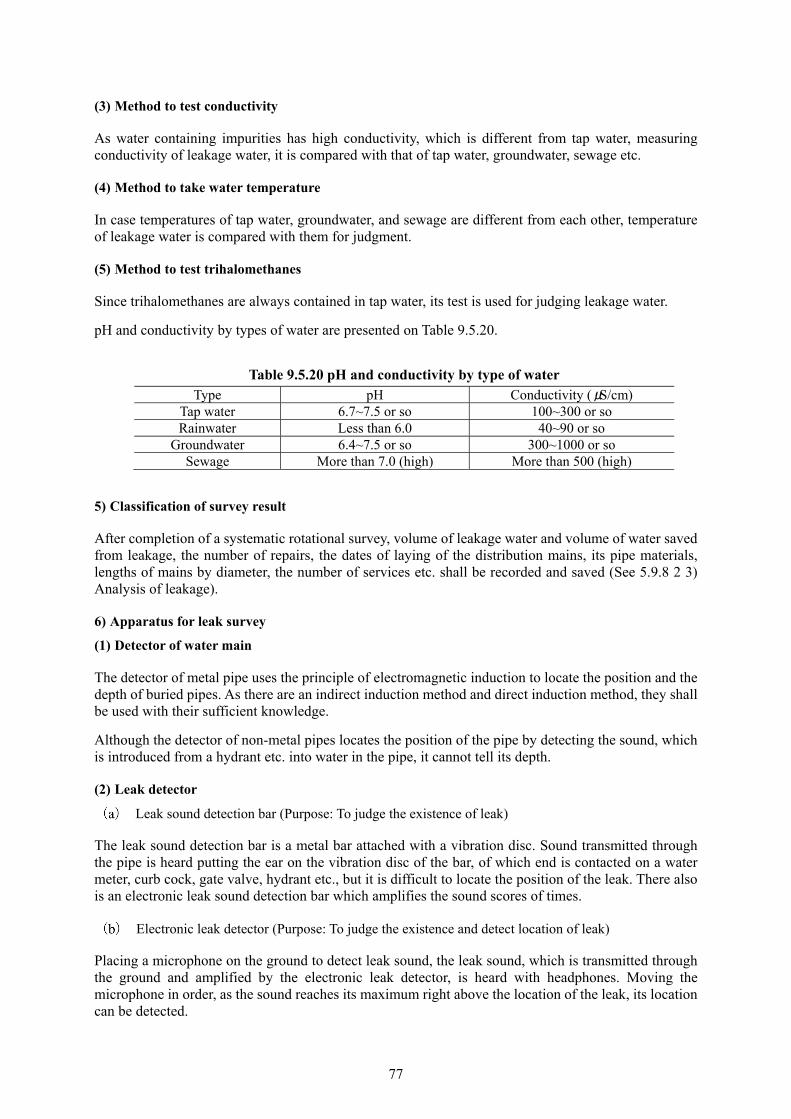
77
(3) Method to test conductivity
As water containing impurities has high conductivity, which is different from tap water, measuring conductivity of leakage water, it is compared with that of tap water, groundwater, sewage etc.
(4) Method to take water temperature
In case temperatures of tap water, groundwater, and sewage are different from each other, temperature of leakage water is compared with them for judgment.
(5) Method to test trihalomethanes
Since trihalomethanes are always contained in tap water, its test is used for judging leakage water.
pH and conductivity by types of water are presented on Table 9.5.20.
Table 9.5.20 pH and conductivity by type of water Type pH Conductivity (μS/cm)
Tap water 6.7~7.5 or so 100~300 or so Rainwater Less than 6.0 40~90 or so
Groundwater 6.4~7.5 or so 300~1000 or so Sewage More than 7.0 (high) More than 500 (high)
5) Classification of survey result
After completion of a systematic rotational survey, volume of leakage water and volume of water saved from leakage, the number of repairs, the dates of laying of the distribution mains, its pipe materials, lengths of mains by diameter, the number of services etc. shall be recorded and saved (See 5.9.8 2 3) Analysis of leakage).
6) Apparatus for leak survey
(1) Detector of water main
The detector of metal pipe uses the principle of electromagnetic induction to locate the position and the depth of buried pipes. As there are an indirect induction method and direct induction method, they shall be used with their sufficient knowledge.
Although the detector of non-metal pipes locates the position of the pipe by detecting the sound, which is introduced from a hydrant etc. into water in the pipe, it cannot tell its depth.
(2) Leak detector
Leak sound detection bar (Purpose: To judge the existence of leak)
The leak sound detection bar is a metal bar attached with a vibration disc. Sound transmitted through the pipe is heard putting the ear on the vibration disc of the bar, of which end is contacted on a water meter, curb cock, gate valve, hydrant etc., but it is difficult to locate the position of the leak. There also is an electronic leak sound detection bar which amplifies the sound scores of times.
Electronic leak detector (Purpose: To judge the existence and detect location of leak)
Placing a microphone on the ground to detect leak sound, the leak sound, which is transmitted through the ground and amplified by the electronic leak detector, is heard with headphones. Moving the microphone in order, as the sound reaches its maximum right above the location of the leak, its location can be detected.
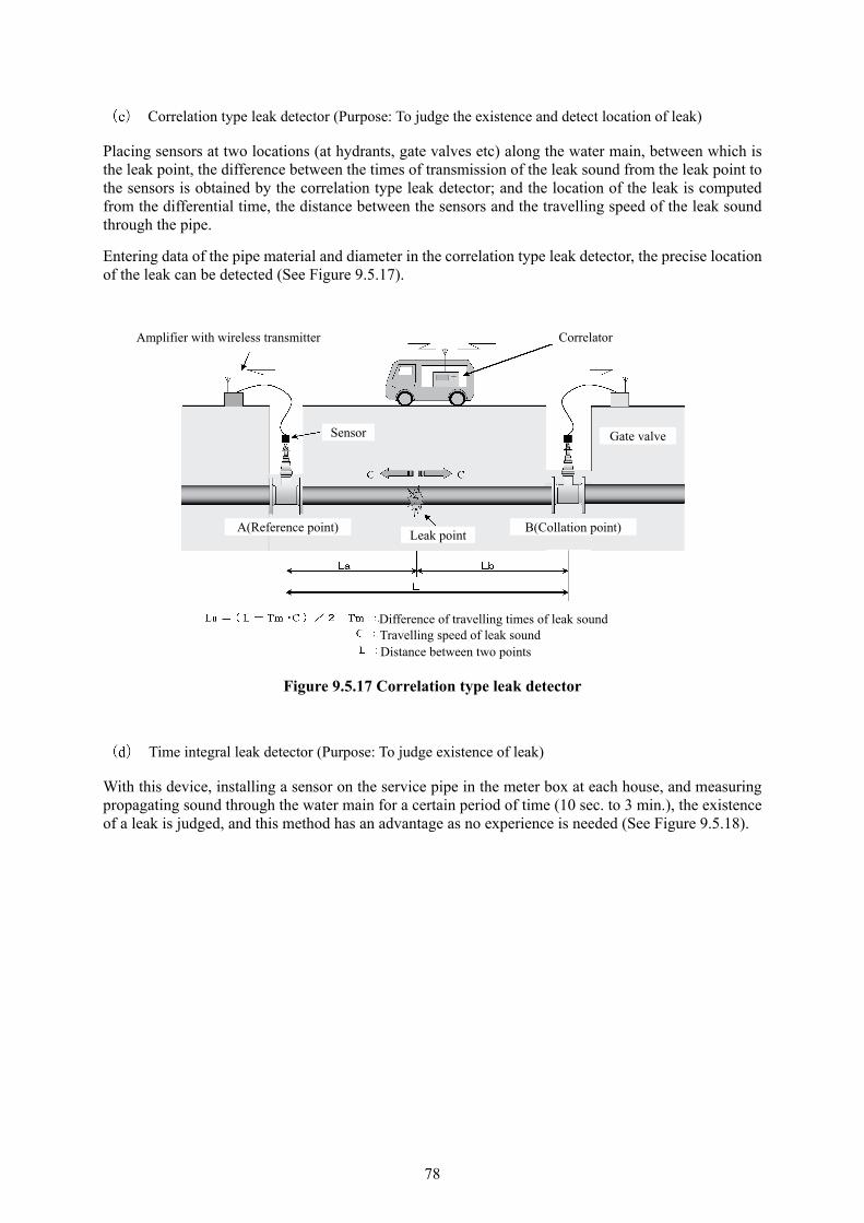
78
Correlation type leak detector (Purpose: To judge the existence and detect location of leak)
Placing sensors at two locations (at hydrants, gate valves etc) along the water main, between which is the leak point, the difference between the times of transmission of the leak sound from the leak point to the sensors is obtained by the correlation type leak detector; and the location of the leak is computed from the differential time, the distance between the sensors and the travelling speed of the leak sound through the pipe.
Entering data of the pipe material and diameter in the correlation type leak detector, the precise location of the leak can be detected (See Figure 9.5.17).
Figure 9.5.17 Correlation type leak detector
Time integral leak detector (Purpose: To judge existence of leak)
With this device, installing a sensor on the service pipe in the meter box at each house, and measuring propagating sound through the water main for a certain period of time (10 sec. to 3 min.), the existence of a leak is judged, and this method has an advantage as no experience is needed (See Figure 9.5.18).
Amplifier with wireless transmitter Correlator
Sensor Gate valve
A(Reference point) B(Collation point) Leak point
Difference of travelling times of leak sound Travelling speed of leak sound Distance between two points

79
Figure 9.5.18 Time integral leak detector
Leak zone tester (Purpose: To judge existence of leak)
With the leak zone tester, catching the leak sound transmitting through water mains and water by submersible microphone set in a hydrant, it is heard with headphones. Moreover, water pressure can also be measured at the same time by a water pressure sensor (See Figure 9.5.19).
Figure 9.5.19 Leak zone tester
(3) Other devices
Underground probe radar
The underground probe radar emits electric waves from an antenna on the ground surface, receives electric waves, which reflect from the earth, air or boundaries of the water main, and find the situation of burial and the location of voids in the earth by analyzing the turnaround time and strength of electric waves.
Leak judgment apparatus
As the apparatus to judge whether or not the leaking water is tap water, residual chlorine meter, pH meter, conductivity meter, thermometer etc. are used.
Automatic leak detector
Acceleration sensor
Meter
Leak point
Distribution submain
Service pipe
Leak zone tester
Ground surface
Impact sound
Stream sound
Fricative sound Sound of vibrating pipe Leak sound through water
Water main
Hydrant Submersible microphone

80
7) Points of consideration for consignment
In case leak prevention work is consigned, the scope of consignment shall be determined in accordance with the actual status of the water utility.
In consideration that high degree of experience is needed for a consigned work depending on its components, the consigner shall carefully be selected. The specification for consignment shall include such items as the type of survey (house-to-house leak sound detection survey and road surface leak sound detection survey), apparatus to be used, to or not to implement night minimum flow survey · water pressure test, submission of the work plan · job diary and so forth.
Besides, the term of the consignment for repair work shall be a full year so that an unexpected leakage accident can also be attended.
4. Preventive measures
As a fundamental measure for the prevention of leakage, such a preventive measure to eliminate the cause of leakage as replacement of water mains shall be implemented.
1) Improvement of distribution mains
As for the improvement of distribution mains, reference “9.5.5 Replacement plan for water mains”. Still more, in regard to the bell and spigot joint (faucet joint), as a temporary measure for water mains replacement, efforts shall be made to implement preventive measures against an accident by means of fitting devices for leakage prevention.
2) Improvement of service pipes
In many cases, since the major portion of leakage is originated from service pipes, the following measures shall be undertaken:
A saddle type corporation tap shall be employed for branching of services from the distribution submain.
In addition, pipe materials of such property suitable to pipe laying as flexibility and anti-corrosiveness
shall be used for the service pipe.
In locations of a road where several service pipes are laid in parallel, or many service pipes are crossing
a broad road, a new distribution submain shall be laid so that crossing service pipes can be eliminated.
An example of rearrangement of service pipes is illustrated in Figure 9.5.20.
Since curb cocks placed in a road is affected by traffic loads, they shall be moved inside the house
premises as much as possible.
Water meters shall be relocated to a location inside the house premises as close to the road as possible.
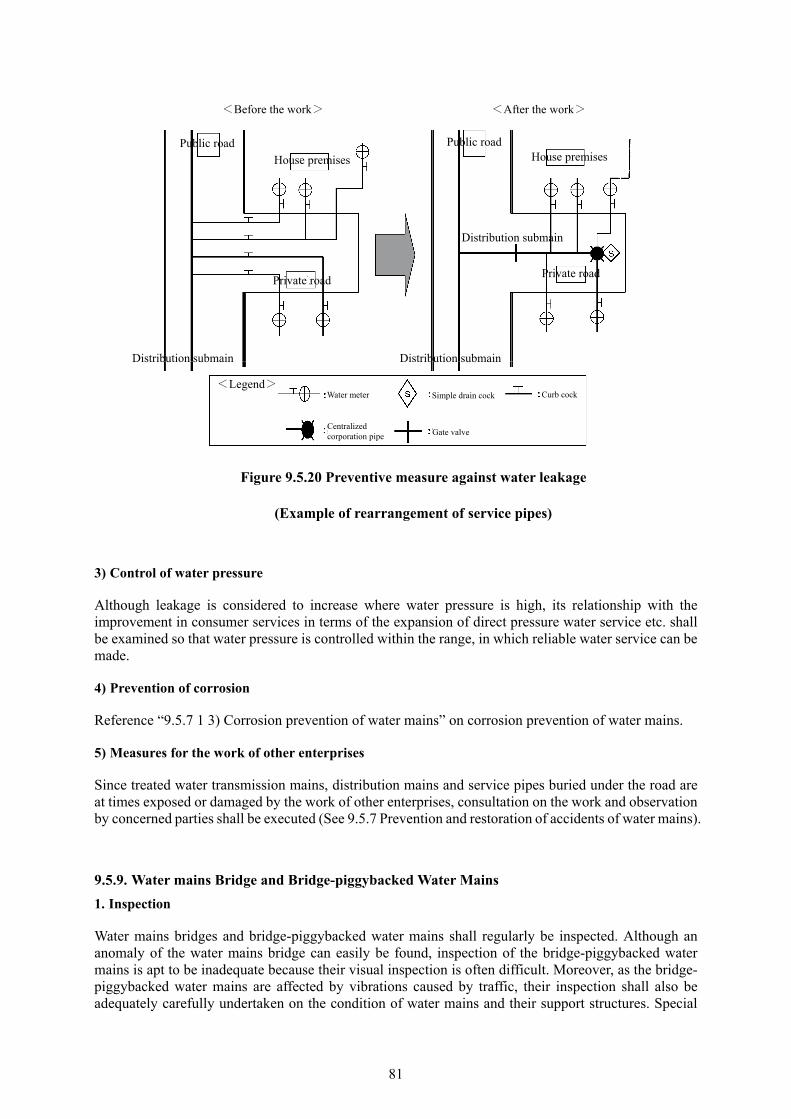
81
Figure 9.5.20 Preventive measure against water leakage
(Example of rearrangement of service pipes)
3) Control of water pressure
Although leakage is considered to increase where water pressure is high, its relationship with the improvement in consumer services in terms of the expansion of direct pressure water service etc. shall be examined so that water pressure is controlled within the range, in which reliable water service can be made.
4) Prevention of corrosion
Reference “9.5.7 1 3) Corrosion prevention of water mains” on corrosion prevention of water mains.
5) Measures for the work of other enterprises
Since treated water transmission mains, distribution mains and service pipes buried under the road are at times exposed or damaged by the work of other enterprises, consultation on the work and observation by concerned parties shall be executed (See 9.5.7 Prevention and restoration of accidents of water mains).
9.5.9. Water mains Bridge and Bridge-piggybacked Water Mains
1. Inspection
Water mains bridges and bridge-piggybacked water mains shall regularly be inspected. Although an anomaly of the water mains bridge can easily be found, inspection of the bridge-piggybacked water mains is apt to be inadequate because their visual inspection is often difficult. Moreover, as the bridge-piggybacked water mains are affected by vibrations caused by traffic, their inspection shall also be adequately carefully undertaken on the condition of water mains and their support structures. Special
<Before the work>
Public road
House premises
Private road
Distribution submain Distribution submain
Distribution submain
Private road
House premises
<After the work>
Public road
Water meter <Legend>
Centralized corporation pipe
Simple drain cock Curb cock
Gate valve

82
attention shall be paid in case they are influenced by sea water.
Inspection shall also be carried out on uneven subsidence of abutments and piers of the bridge, cracks in concrete, damage of protection work for piers, items of description on the noticeboard for exclusive use, damage of anti-freezing insulation material in a cold region, and water leakage from air-valves.
Likewise, in addition to regular inspections, careful inspection shall be executed after a heavy rain and an earthquake. In case regular and ad hoc inspections have been performed, their results shall be recorded so that proper maintenance is undertaken. An example of a table for inspection on maintenance of a water mains bridge is given on Table 9.5.21.
Table 9.5.21 Table for inspection on maintenance of a water mains bridge Date of
inspection Year month day Name of staff Index
Location Right Bank
Serial No.
Left bank
Drawing No.
Name of pipe bridge
Type of bridge Independent, bridge-piggybackedPipe material SP, FCD, FC, SUS
Diameter mm As-built drawing No.
Name of river etc.
Date of previous painting
Spec. of painting
Painting, anti-corrosion cloth, FRC, plastic tape
Environmental condition *Note 1
Expansion pipe
Dresser type, Victaulic type, closure joint, bellows type
Air valve Air valve
Existence of leak, date of
repair
Existence: yes or no (Year month day)
Location of leak Pipe body, expansion pipe, joint, welded section, air valve, ( )
Status of premises of
facility
Good, damaged fence etc., illegaldumping of waste, illegal occupation
Condition of abutment section
Good, bad (crack, damage, others)
Status of cladding Good, bad (deteriorated, discolored, pealing-off, others) Section Item
Pipe Body
Expansion joint
Prohibition of pedestrians
Method of evaluation *Note 2
Rust 1. Sound2. Almost sound 3. Deteriorated 4. Severe deterioration (According to the Standard photo album on degree of coating deterioration)
Pealing-off
Discoloration, Faded color
Stain
Synthetic evaluation of
painting
1. No need for repainting for the time being2. There is a need to repaint in several years. 3. Early repainting is needed.
*Note 1 General environment: Environment not affected by airborne salt, and not strongly influenced by automobile exhaust gas and soot and smoke from factories Relatively severe environment: Environment affected by airborne salt, or strongly influenced by automobile exhaust gas and soot and smoke from factories Severe environment: Environment with sea breeze strongly blowing so heavily affected by airborne salt.
*Note 2 In the cases of Evaluation 3 and 4: In case there are leakage and repaired part, Photos of the status shall be attached. In case there is an anomaly in the status of the cladding and the abutment, do the same.
2. Repair
1) Repair of expansion joint
Expansion joints are classified into the sliding type, the bellows type, rubber type etc. It is needed to adequately understand the characteristics of these types so that repair suitable to the respective types can be made.

83
2) Repainting
The outside surface of the water mains bridge and the bridge-piggybacked water main easily get dewed, so are under severe situation as condensation and drying repeat. Although the life of painting differs depending on the environment of setting, the standards for external painting of water mains bridge (WSP 009-2004) (Japan Water Steel Pipe Association) can be referenced as for the standard time interval for repainting.
Moreover, the record of painting as to the date of work, materials of paint, the name of contractor etc. shall be posted at a place for easy attention. An example of noticeboard to be made at the completion of painting work is illustrated in Figure 9.5.21.
Date of painting (year) (month) 1st primary _______Painting Co., Ltd Painting company 2nd coat ______________ Co., Ltd Final coat _______Painting Co., Ltd 1st primary _______Painting Co., Ltd Paint material 2nd coat _______Painting Co., Ltd Final coat _______Painting Co., Ltd 1st primary ______________ Co., Ltd Paint manufacturing company 2nd coat ______________ Co., Ltd Final coat _______Painting Co., Ltd
Figure 9.5.21 Example of a noticeboard at completion of painting work
4. Safety facilities
Such safety facilities as a passage way shall be provided for inspection, repainting and maintenance of air valve, expansion joint, fastening fittings etc. mounted on the water mains bridge and so forth.
9.5.10. Seabed treated water transmission mains (Annotation is omitted)
9.5.11. Pipe laying in the multipurpose underground utility conduit (Annotation is omitted)
9.5.12. Treated water transmission conduit (Annotation is omitted)
9.6. Facilities as measures against an earthquake (Annotation is omitted) 9.6.1. General (Annotation is omitted)
9.6.2. Water tank as measures against an earthquake (Annotation is omitted)
9.6.3. Large capacity treated water transmission mains (Annotation is omitted)

84
9.6.4. Interconnection water mains as measures against an earthquake (Annotation is omitted)
9.7. Ancillary Facilities 9.7.1. General
As ancillary facilities of treated water transmission and distribution mains, there are valves, air valves, hydrants, reducing valves, emergency cut-off valves, drain facilities, manholes, flow meters, pressure gauges, automatic water quality analyzers etc. These ancillary facilities need to function together with the water mains so that proper water flow, pressure and quality are maintained.
What’s more, as to their maintenance, special caution needs to be practiced when carrying out daily inspection and upkeep of boxes and iron lids, which accommodate ancillary facilities and valve boxes, since the their proper maintenance largely affects traffic of pedestrians and vehicles.
9.7.2. Valves
Valves are important facilities to be installed for control of water flow and pressure, setting of the service area etc. As such, a notice card describing the valve serial number, the direction and number of rotation shall be posted inside the valve room or box as a measure to prevent erroneous operation of the valve, which is in use at complete closure or half-open, clearly indicating the aperture of the valve. As for valves on the trunk water main, cleaning and oiling of rotating parts and a function test for confirmation of its opening and closure shall be conducted; rainwater or wastewater from the valve room (box) shall regularly be drained; and attention shall also be paid to the damage to the valve room (box) and iron lid. As for valves, which are not operated for a long time, such maintenance as confirming the closure of the valve shall be made so that the valve can always be operated..
When entering a valve room, oxygen concentration and the existence of hazardous gases shall be measured in advance to secure safety, and sufficient ventilation shall also be provided during the work.
9.7.3. Air valves
Air valves are installed to discharge the air, which enters in water mains and then separate from the water, out of the water mains, and inhale air at the time of the work of draining water from them. Inspection and upkeep of the air valve shall adequately be practiced since there is a case the float valve, which is a plastic or ebonite ball and the main body of the air valve, gets stuck to the rubber gasket on the upper valve seat and does not fall causing impairment of inhalation and discharge functions. The valve room shall always be kept clean as wastewater, dirt etc. are sucked into the water main especially at a time of suspension of water service.
Besides, there is a hydrant attached with an air valve forming one body, of which functions are structurally separate. This has an advantage in that less special fittings, valve rooms etc. than the normal case are needed since there is no need to install the air valve and the hydrant separately.
9.7.4. Hydrants
The hydrant is an important facility because it plays diverse roles of not only supplying fire-fighting water but also measurement of water pressure, water quality etc., cleaning and drainage of distribution mains and so on.
In case the hydrant breaks down, the fire department shall urgently be notified, and it should immediately

85
be repaired. In this occasion, the repair valve attached to the hydrant shall also be kept up.
9.7.5. Reducing Vales
For the reason that the action of the reducing vale is sensitive, and its function tends to become low due to sand, rust etc., monitoring of its secondly side pressure by a self-recording pressure gauge, regular inspection and upkeep are needed.
Valves for inspection and repair shall be installed upstream and downstream of the reducing valve. In addition, a bypass pipe shall be laid so that status of shutdown is not brought about, and a drainage facility shall be attached to the bypass pipe.
Monitoring by a telemetry device shall be carried out for a reducing valve, which is important in terms of water distribution control. --
9.7.6. Emergency cut-off valves
In case any anomalies occur in water mains, the emergency cut-off valve automatically shuts off to prevent collateral disasters by draining water and reserve stored water, so its installation on the service reservoir etc. is urgently needed as stated in the “Water Supply Vision” as well. In as much as it is prerequisite for the emergency cut-off valve to always function precisely and steadily at an emergency, it shall regularly be inspected and kept up, and its function shall be confirmed.
9.7.7. Flow meters and water pressure gauges
The flow meter and the water pressure gauge are indispensable facilities for smooth and proper control of water distribution.
Since the data of the flow meter and the water pressure gauge largely influence the volume of distributed water and water distribution control depending on their accuracy, their inspection and maintenance shall regularly be undertaken, and their precision need to be tested and calibrated.
9.7.8. Drainage facilities
The drainage facilities are facilities installed at the bottom of the water main to drain water at times of discharging impurities in the water main; suspension of water service; and an accident, so their inspection and repair shall properly be carried out. With drainage facilities installed on the bypass pipe of the flow control valve, the reducing valve, the emergency cut-off valve, the flow meter etc., drainage of stagnant water in the bypass pipe will become easy at the times of inspection and overhaul of facilities.
As these facilities are essential for satisfactory maintenance of water quality, they shall systematically be installed at effective points in the existing water main.
9.7.9. Manholes
Manholes are provided to be used for such maintenance as workers’ access into the water main and inspection, repair etc. of its inside in case water mains of a diameter of more than 800 mm is laid. Their ordinary maintenance shall be undertaken along with inspection and upkeep of air valves, and special attention shall be paid to leakage and corrosion of the manhole room and lid.
86
9.7.10. Automatic water quality analyzers
The automatic water quality analyzer is a useful instrument for smooth water quality control of water distribution facilities, quick response to an emergency and labor saving in the system of water quality testing.
Although the automatic water quality analyzer possesses functions of various automatic calibrations and cleaning of probes to continuously measure for a long time, regular inspection and maintenance need to be undertaken so as to ensure reliable performance.
9.7.11. Cathodic Protection Facilities
Cathodic protection facilities are to prevent deterioration of pipe materials by corrosion, and facilities to lengthen the life of water mains and suppress the occurrence of leakage accidents etc. As its methods, there are the external electric source method, the galvanic anode method, the forced discharge method etc.
When examining the facilities, such detailed checking as measurement of the galvanic anode current, measurement of the pipe-to-earth potential etc. are needed. The result of checking shall be recorded on a register.
9.7.12. Telemetry Facilities
The telemetry facilities are the facilities to remotely monitor data of water volume, pressure, water quality etc. also including a simple one which is employed in case the volume of data is small. The telemetry apparatus for transmission of information related to control and fast and large capacity data, and the one for transmission of slow and small capacity date of small scale water distribution facilities etc. shall separately be installed.
9.7.13. Items of consideration to cold regions (Annotation is omitted)
9.8. Information Management 9.8.1. General
Because of huge volume of information related to water distribution facilities, the quality of operation and maintenance, and management is determined depending on the manner of information management. As for the method of information management, the one, which can rapidly treat the information, of which renewal and processing are easy, and which can be stored for a long time, is good. Although printed drawings, microfilm, registers etc., have traditionally been in use, the mapping system with the use of computer (geographical information system or water mains information system) and the filing system are widely used.
To construct a high level water supply system, such detailed management of information as precisely understanding the status and function of water mains and their ancillary facilities, so the use of computer is inevitable.
87
1. Centralized management of information
In case the same information is stored by more than two sections, and correction and addition to it are made by the respective sections, there is a risk that the information becomes different from a section to another due to its erroneous handling, inadequate means of its communication etc. For operation and maintenance at normal times and quick response at an emergency, centralized information management, under which sources of information are concentrated in one place, is indispensable.
2. Protection of personal information
Many of local governments impose conditions for handling of personal information under their bylaws etc.
Since personal information may leak if drawings and registers, which contain such personal information as names of customers, service fittings etc., are disclosed to the public, it is important to clarify which items of information is personal information and which can be released.
3. Backup of data
Regarding various items of information, it is essential to backup data in addition to the ones to be used daily irrespective of the method of information management. Especially, in the case of the mapping system, regular backup of data is needed because the data are any time renewed.
9.8.2. Management of Drawings
To properly maintain treated water transmission and distribution facilities, drawings and registers need to be systematically classified and stored based on as-built drawings so that the concerned staff can at any time use the drawings and registers suitable to the purpose of use.
With such provisions, preparation of a plan for inspection and maintenance, steady response to an accident and a disaster and construction work of other enterprises etc. can precisely be undertaken.
1. Provision of drawings
The drawings of treated water transmission and distribution mains ordinarily consist of pipe laying drawings and detailed drawings. Since pipe laying drawings are divided into small, medium and large scale drawings, if they are made in accordance with the 1/5,000 basic land map, the 1/2,500 city plan map, and the 1/500 road register map, exchange of information with other systems will become convenient.
Additionally, with the use of the topographical maps with application of public coordinates on the basic pipe laying map (topographical map), transitions to the mapping system will be easy.
1) Pipe laying drawings
(1) Small scale pipe laying drawings
For the purposes of identification of the topography, and the use for the layout of facilities, planning water distribution, planning construction work, measures against disasters etc., pipe laying drawings in a small scale of 1/10,000 to 1/50,000 or so are used.
Items to be printed are the shapes and layout of the water treatment plant, service reservoir, the locations and diameters of principal water mains, details of principal valves and location of interconnection etc.

88
(2) Medium scale pipe laying drawings
For the purposes of planning water distribution and control of water distribution, pipe laying drawings in a medium scale of 1/2,500 to 1/5,000 or so are used.
Items to be printed are the pipe material, diameter, valve, air valve, hydrant, reducing valve, drain pipe, inverted siphon, water mains bridge, bridge-piggybacked water mains etc.; and they shall clearly be indicated using symbols. In addition, facility numbers to be entered in the register etc. shall be added.
Moreover, locations of idle and abandoned water mains shall also clearly be stated. Besides, such complex sections as duplicated water mains, crossing, branching etc. shall be illustrated in the margin in a large scale.
(3) Large scale pipe laying drawings
They are the drawings with the highest accuracy as pipe drawings, and describe the raw water transmission mains, treated water transmission and distribution mains, and service pipes. In general, drawings of 1/500 scale are used.
Items to be printed shall be added to medium scale pipe laying drawings, including the material of service pipe, the diameter of the corporation tap branching from the distribution water main, the location of the curb cock, meter diameter, existence of the receiving cistern etc., which shall clearly be indicated.
Secondly, the tap number and the name of the customer shall be stated at the location of each house as the information related to the customer, which will make reference convenient.
2) Detailed drawings
The topography, the main land mark on the ground, the river, the location of railroad crossing, the distance from other buried object etc. shall be stated in the profile and the plan of treated water transmission and distribution mains. Besides, as to the valve room etc., their structures shall be recorded as much in detail as possible.
Detailed drawings can be provided based on the level of importance of water mains. For example, there is a method to prepare detailed drawings for the trunk mains and those with the equivalent priority. Besides, it is also a good method to sort and store as-built drawings instead of detailed drawings.
3) As-built drawings
Since as-built drawings make the basic data for preparing and correcting pipe laying drawings, they shall securely be sorted and stored. It is convenient to store them using microfilm and the filing system if the volume of drawings is large.
2. Correction and storage of drawings
Corrections to drawings shall at any time be made to precisely reflect the resent status of the facilities as the situation of treated water transmission and distribution mains frequently changes due to their replacement, new laying, relocation etc.
1) Method of correction
Correction to drawings is the work to enter water mains and their ancillary facilities, the topography in respect to roads, information on houses etc. based on the as-built drawings and site surveys. In case the drawings are made in more than two scales, efficiency of the work shall be considered applying such an idea as to first implement the correction of drawings in a large scale, carry out in succession the work on the small and medium scale drawings and so forth.
89
Especially, an organization to quickly and securely communicate such information as as-built drawings and the change in their ancillary facilities necessary for correction of drawings to the section in charge of the correction needs to be established.
2) Method of storage
Although there are methods to use paper, microfilm, and computer as the methods of storage of drawings, duplication of storage as the one used daily and the other one for backup, and its decentralization shall be considered irrespective of the method.
In the case of storage by printed paper, although the drawer type is inconvenient since drawings are piled, smaller space is needed than the hanging type. With the hanging type, it is convenient to withdraw and stow; and it gives small chance of damage.
In the case of microfilm, one for backup shall be stored in a room with small change in room temperature to prevent its deterioration.
9.8.3. Management of registers
As to management of facilities, although understanding of their present status is the most important, there is limitation in the information which can be described in the drawings. Therefore, registers shall also be prepared to accommodate data which cannot be entered in the drawings.
1. Water mains facilities
The information to be described in the drawings is mainly information on water mains, and not necessarily adequate for the work of water distribution control.
Given this, to be used for not only daily operation and maintenance (O&M) and water distribution control but also maintenance and replacement, registers containing hydraulics, water quality, accidents, claims, burial environment, social information etc. shall be provided.
2. Ancillary facilities
Since valves are important facilities for water distribution control, a valve register shall be prepared in addition to the registers for water mains. For entry in the valve register, information on the types of valves, diameters, aperture, history of operation and inspection and upkeep, drawings of offset of valve rooms etc. shall be sorted to make a register, which can easily be used at site as well. Moreover, registers for such ancillary facilities as hydrants, air valves, pumps etc., water mains bridges, and bridge-piggybacked water mains shall also be prepared.
The register for water mains bridges etc., shall come in a form, which allows sorting of record of such upkeep as permission for exclusive occupation, inspection, repainting etc. An example of a register for ancillary facilities is presented in Figure 9.8.1.--
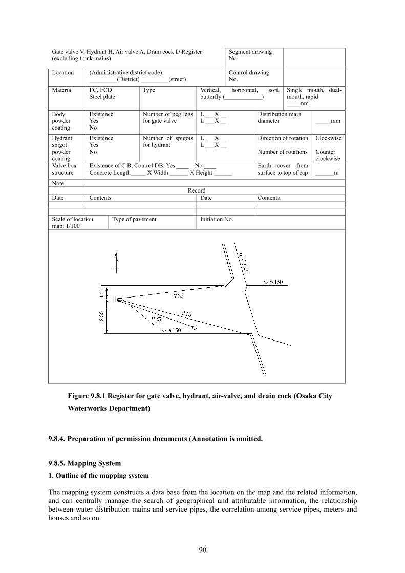
90
Gate valve V, Hydrant H, Air valve A, Drain cock D Register(excluding trunk mains)
Segment drawingNo.
Location (Administrative district code) _________(District) _________(street)
Control drawingNo.
Material FC, FCD Steel plate
Type Vertical, horizontal, soft, butterfly (____________)
Single mouth, dual-mouth, rapid ____mm
Body powder coating
Existence Yes No
Number of peg legs for gate valve
L ___X __L ___X __
Distribution main diameter
_____mm
Hydrant spigot powder coating
Existence Yes No
Number of spigots for hydrant
L ___X __L ___X __
Direction of rotation Number of rotations
Clockwise Counter clockwise
Valve box structure
Existence of C B, Control DB: Yes ____ No ____Concrete Length_____ X Width ______ X Height ______
Earth cover from surface to top of cap
______m
Note Record
Date Contents Date Contents Scale of location map: 1/100
Type of pavement Initiation No.
Figure 9.8.1 Register for gate valve, hydrant, air-valve, and drain cock (Osaka City
Waterworks Department)
9.8.4. Preparation of permission documents (Annotation is omitted.
9.8.5. Mapping System
1. Outline of the mapping system
The mapping system constructs a data base from the location on the map and the related information, and can centrally manage the search of geographical and attributable information, the relationship between water distribution mains and service pipes, the correlation among service pipes, meters and houses and so on.

91
For construction of a mapping system, data with accuracy necessary for the achievement of the purpose shall be prepared and data replacement system for maintaining the accuracy shall be provided.
1) Centralized management of information
With the mapping system, information can be centrally managed for the reason that, once entering any information, the data of the drawings and registers can simultaneously be corrected and added.
2) Rapid application of information
The work of search, summation, processing of information can speedily and precisely be conducted, which makes the work efficient.
2. Structure of the mapping system
1) Hardware
It is important to select hardware of the mapping system in consideration of prerequisite functions and the relationship with other systems, and its extensibility will be improved by enhancing the network function. As for the client server system, as cost reduction in system construction, building of respective parts and their partial replacement can be made, there are many cases of the application of this system. For application for a small installation, the stand-alone system is rational.
2) Software
The standard structure of software for the mapping system is as illustrated in Figure 9.8.2.
Figure 9.8.2 Software structure of the mapping system
As management of the database and the graphic data processing package, there are the method to use the all-purpose geographic information system and the method to be developed uniquely.
In case the all-purpose geographic information system is used, basic functions are provided from the beginning whereas the characteristics of the water utility cannot be reflected. On the other hand, in case the basic software is developed on the utility’s own terms, there are such merits that extensibility for the future and the characteristics of the utility can be taken into consideration or the like.
3) Database
The database for the mapping system is composed of graphic information and attributable information, so sorting of data is needed for their uses in various tasks.
Com
mun
icat
ion
proc
essi
ng
pack
age
Graphic data processing
package
Application programs
Dat
a ba
se m
anag
emen
t pac
kage
Operating system
92
The graphic information includes not only water mains to be entered in the map but roads, houses etc., of which structure shall be made easy to use by their grouping and stratification so as to fit to respective purposes of use
The indigenous information (pipe material, diameter etc.) of respective parts of this graphic information is named attribute information, and shall be selected according to the contents of tasks to be implemented by the mapping system.
If the database is excessively large, search time will become long, and the cost of building the system will become big. As such, it is important that the existing tasks shall precisely be analyzed; information to become the database shall be chosen; and the capacity of the memory shall be as large as to have certain spare capacity to accommodate additional data.
3. Construction of the system
When constructing the system, the existing tasks of respective sections, which use the information related to water mains, shall be studied in detail, and the organization system, the flow of work, the status of preparation of data etc, shall be identified so that the tasks to be transferred to the system are determined.
Considering that construction of the system is not carried out for the single purpose of the management of drawings and registers, the following tasks need to be tackled:
1) Preparation of data
The cost needed for preparation of data constitutes large part of the cost of the mapping system project, and the more the types of information to be incorporated in the database, the bigger the cost. Since the information related to water mains changes day by day, it is important to securely and precisely carry out update of data.
2) Construction of the system of operation
To carry out upgrading and optimization of operation, it is important to maintain synchronization between the actual situation of the facilities and the data to be managed by the mapping system. Therefore, it is needed to develop a system and mechanism to quickly update the data in accordance with the changes in the situation of the facilities during their daily operation.
3) Preparation of hardware and software
As to preparation of the hardware and the operating system (OS) of the computer, their acquisition by a lease is more likely than a purchase to be able to flexibly deal with the progress in the information technology, and reduce the risk of obsolescence of the system.
As the OS, it is considered a rational way to adopt an all-purpose geographical information system, on which a mechanism of water mains management shall be constructed. Furthermore, the implementation of various surveys by a pilot system can reduce the future risk in the development of software, and preparation, input and updating of data to a minimum.
4) Items of consideration for development of the system
In the stage of developing specific programs, adequate consultation with the contractor in charge of system development shall be conducted to decide the specification on such details as the ease of handling etc. On such an occasion, it is important to effectively utilize the existing database from cost saving point of view.
What’s more, in case another system has been introduced, it is important to construct a system, which can interchangeably be used with the former, and undertake reduction in operating cost, smoothing of
93
operation, and saving in office space.
5) Organization for operation of the system
For operation of the system, a section in charge of maintenance of such facility as the computer, and an upkeep section in charge of appropriate correction of the database are needed, so an organization for operation shall be established in accordance with the present status of the respective water utilities.
The database shall regularly be updated after its commissioning, and the information, which has been found in various construction works etc., shall also be one by one added to the database. Synchronization shall be made between the actual burial condition of water mains and the data managed by the system so that improvement in the accuracy of the information on water mains is to be achieved.
6) Security measures
Security measures are needed against the unauthorized use of computer (unauthorized copy of information, input of wrong data, manipulation of data etc.) and destruction of data.
There are such security measures as follows:
Natural disasters (earthquake, typhoon, fire etc.)
Trouble of the computer system (failure of hardware, bug of software, failure of communications
circuits, erroneous transmission etc.)
Operational mistake of the computer system (mishandling, erroneous use or loss of files etc.)
Computer crimes (unauthorized connection, theft and loss of data etc.)
9.8.6. Road management system (Annotation is omitted.)

94
10. Water Service Fittings 10.1. General 10.1.1. Basic Items
1. Present status of management of water service fittings
The water service fittings are a concept unique to water supply utilities and composed of “the water service pipe branching from a water distribution main, which is built by a water supply utility to supply water to the consumers, and water service appliances directly connected to the former” as defined in the Waterworks Law (1957 Law No. 177, Article 3, Close 9). Namely, the water service fittings Note 1) are part of the “water supply facilities” Note 2) together forming one body, and their scope is the structure, which is not easily detached, from the corporation tap on the water distribution main through the discharging mouth of water service appliances served under pressure. Additionally, to reliably serve safe water up to the tap at the terminal end, the standards on “the structure and material of water service fittings” are enacted (Waterworks Law Ordinance Article 5) (Hereinafter, “Standards on the structure and materials”)
Note 1) Water supply facilities stand for raw water intake facilities, raw water transmission facilities, water treatment facilities, treated water transmission facilities and water distribution facilities for water supply, which come under the management of the concerned water utility, bulk water supply utilities, and exclusive water suppliers. (Waterworks Law Article 3 Clause 8)
Note 2) Water supply denotes the whole of facilities which supply water as water suitable for drinking by means water pipe and other structures. (Waterworks Law Article 3 Clause 1)
The reason why the water service fittings are defined as the fittings up to the mouth of the water service appliances is to confirm the two points below from the viewpoint of prevention of tap water pollution:
Confirmation is required for the water service fittings to comply with the standards for elution in
“Ordinance for the standards for the structure and materials of water service fittings” (1997 Ministry of
Health and Welfare Ordinance No. 14) (Hereinafter, “Standards on the structure and materials”)
In the case of water tanks, sinks, other device to receive water, water service for facilities, confirmation
is required if the water service fittings have proper provision to prevent backflow prescribed in the
“Standards on the structure and materials”.
On the other hand, the administrative responsibility of the water service fittings shall comply with the close of the Waterworks Law Ordinance: “A clause on the responsibility of consumers is provided in the water service bylaw to be enacted by the water utility.”(Waterworks Law Ordinance Rule Clause 12-2, Article 1, Section 2, _); in other words, the components from the corporation tap on the water distribution main downstream (the tap side) are termed the water service fittings, and their owner and responsibility to manage them are attributable to the consumer.
However, as the reality, since the water utility is obliged to comply with the water quality prescribed in Clause 4 of the Waterworks Law for water to be supplied from the water service appliances fit at the end of the water service fittings; and some water utilities repair leakage and improve lead pipes for free in the road and within part of house premises, it is unclear who is the main subject of responsibility from the consumer’s point of view
In this manual, the role of the water utility with regard to maintenance of water service fittings is mainly defined with the above situation in mind also from consumer’s point of view etc.
Besides, operation and maintenance as referred to in this chapter is termed the deed to upkeep the water service fittings and maintain them in good condition, so is the synonym to management.

95
Although, with the diversification of life style, the purpose of water use etc., various water service appliances
have been developed with the aim for improvement in convenience of the appliances, there are many of them
for which regular maintenance is considered to be required.
3. Structure of water service fittings and assurance of the quality of their materials
To prevent water pollution by water service fittings, their structure and material are stipulated in the Waterworks Law. In case the structure and material of the water service fittings of an entity, who intends to receive water service from a water utility, are not inconformity with the ordinance of the Ministry of Health and Welfare on standards for the structure and material based on Clause 1 and Clause 2 of Article 5 of the Enforcement Ordinance of the Waterworks Law, the said water utility can refuse the application for water service, or stop water service.
To ensure the structure and material of water service fittings, the condition for water service can be set as the water service fittings are those which are installed by a company designated for the installation. Confirmation, if the service pipe and water service apparatuses are in conformity with the Ministry Ordinance on the standards for the structure and material, shall be made in that the said product is the self-certified one or the one certified by a third party accreditation organization, and has a certificate of quality; or that a product is the one in conformity with the product standard which satisfies the Ministry Ordinance on the standards for the structure and material, and has its certificate.
The standards for the structure and material shall also apply to superannuated water service fittings. Therefore, in case the water service fittings do not conform to the standards for the structure and material as a result of examination by the water utility, or in case it does not conform to the water quality standards due to its inferior material, necessary remedy shall be taken so as to comply with the standards.
4. Safety assurance of water service fittings
Even if water service fittings are properly installed, there is a risk that safety of water is not insured, or undrinkable water may flow back to the distribution main through the said water service apparatus to influence consumers in case (1) service pipe and water service apparatus get aged; (2) their connection to the service pipe or the manner of their use is wrong; (3) the water-discharging gap between the end of the water service fittings and the water surface of the receiving vessel is insufficient.
Examples of (1) are water quality problems caused by deterioration over time of galvanized steel pipe, steel couplings etc.; and functional degradation of backflow prevention caused by superannuation etc. of the check valve. An example of (2) is dangerous connection of the service pipe to such other piping as well water piping, or connection to a car-washing machine or pump etc., which must not be connected to the water supply system, namely, cross connection. Examples of (3) are insufficient air gap between the overflow pipe of a receiving cistern and the discharging mouth of a ball-tap, and dipping of the tip of the water service fittings. These events are highly risky to pollute tap water, so they must absolutely be avoided.
Although water service fittings are generally owned and managed by the consumers, almost all of them do not possess knowledge on their maintenance. As such, the water utility needs to undertake dissemination to and enlightenment of consumers in regard to appropriate handling of the water service fittings through cooperation with licensed contractors of water service fittings (including the chief engineer of water service fittings installation), makers of water service appliances etc.
1) Upkeep of service pipe and water service appliances
It is desirable for water utilities to prescribe the handling of service pipe in the standards for water service in advance in consideration of the case they take consultation from the consumers about how to deal with superannuation of their service pipe.

96
2) Improvement of lead service pipe
Lead pipe was once used as service pipe, and, in some cases, until the problem of lead elution became evident, it was also applied at the joint section of the corporation tap and the service pipe and around the water meter (hereafter, “meter”) as it possesses high flexibility. From nationwide point of view, lead pipe is used in water service fittings from the corporation tap to the meter in the most cases.
Given the high rate of accident of lead pipe, many water utilities have been carrying out replacement of lead service pipe in the road (up to the meter depending on water utilities) in the occasion they change service pipe concurrently with replacement of distribution mains or repair of leakage.
Furthermore, among water utilities which implement the repair of leakage for free from the view points of leakage prevention and improvement in the ratio of revenue water, some ones carry out the improvement of service pipe with other material than lead pipe at the time of repair of leakage.
The fundamental measure for lead service pipes is their replacement. However, if the water utility should undertake replacement of service pipes owned and managed by the consumers, the reason for and funds to meet the cost of such a project will become a big issue.
3) On-site research and on-site inspection
Even though water service fittings are properly installed by a qualified contractor, dangerous connection and piping, which are not in conformity with the structure and material standards, are made at times by an unqualified person for example: connection to a heat exchanger for waste hot water, water softener, car washing machine, cross connection with piping for well water etc. and steam pipe etc., tip of the water service fittings dipping in water in a wash basin for metal plating and so forth. Such illegal connections and piping, which cause backflow resulting in accidents of pollution with hazardous substances or polluted water, and discharged from taps by way of distribution mains, shall never be brought about. It is considered that water utilities need to conduct an on-site research to factories and businesses, which use toxic matters, poisons, dangerous chemicals etc.
5. Expansion of direct pressure water service
Direct pressure water service to medium- and high-rise buildings is the most effective as a means to solve the problem of poor management of receiving cistern facilities, and can lead to improved water service to the consumers.
The matters of consideration on operation and management of direct pressure water service facilities is the regular inspection of the directly connected booster type pump unit. Most water utilities, which have introduced direct pressure water service, impose such a condition for the introduction of the method as the implementation of regular inspection by the maker etc. However, in the case of condominiums, their ownership and management are often transferred to the union of the condominiums after its completion. In the case of rental apartments, the owners and tenants are different, so the situation of their management tends to become unclear. Water utilities shall make efforts to know the status of implementation of regular inspection, and need to promote such owners of condominiums as the management union etc. for the implementation of regular inspection depending on the situation.
6. Cistern type water supply
It is desirable for water utilities to prepare registers related to receiving cistern facilities. The register of receiving cistern facilities shall be managed by means of always updating data to reflect the newest information; is to be shared with such an office of public health administration as health centers; and it is desirable to control the register as the one with the information on the management of the facilities.
The effective capacity of the cistern of the storage tank type water supply is in many cases prescribed in the rule of handling in regard to the design of water service fittings, and is equivalent to “40 to 60% or so of the design daily water consumption”. Although it is construed that. in the case of a condominium,

97
the ground for computation of the design daily water consumption is the unit value of 1 m3/day per house or 250 L/day per capita according to many water utilities, the value of the design daily water consumption computed using the above unit values is considered to be the design daily maximum water consumption which is supposed to be used by the facility. Nonetheless, there are many factors for drop in water consumption such as the spread of water-saving type appliances, the declining birth rates, and increasing number of unoccupied houses in the recent years. Given this, although it was used to be assumed that the water in the receiving cistern was replaced twice every day, in effect, some cases have been reported that it takes more than a day for the water to be replaced. Since the water utility knows the effective capacities of the receiving cisterns, which have been reported, so the daily consumption can be obtained from the metered water volume, the actual situation can be found. Therefore, examining these facts, it is needed to study on how proper effective capacity shall be determined or review of unit values for computation shall be conducted.
Furthermore, depending on the situation, the water utility shall give advice or assistance etc. for making the capacity of the receiving cistern appropriate by means of regulating the water level in it and so on.
10.1.2. Operation and Maintenance of Water Service Fittings
Operation and maintenance (O&M) of water service fittings are in general provided to be the responsibility of the consumers. The piping in the house premises and inside the house is managed in this concept. The matters, for which the water utility shall consider in respect to O&M, are maintenance of the service pipe in the road, and mainly water service appliances to be fit at the end of the water service fittings.
Some of water utilities take over the service pipe in the public road for free. In some cases, the ownership of the service pipe belongs to the consumer while its management is on the water utility. Although either form of management is possible, there are many problems related to the operation of water supply with regard to free handover of the service pipe such as the registration and management of assets, the implementation of demolition at the time of abolition of water service and so forth. Besides, even in case the consumer manages the service pipe from the corporation tap downstream, some water utilities undertake various works at their own cost in that repair of leakage within the road or up to the meter is performed for free, or that they improve the aged service pipe as well along with replacement of distribution mains. These actions are carried out for the prevention of collateral disasters to be caused by water leakage, and from the leakage prevention point of view with the aim for improvement in the revenue water ratio, and the subject of O&M is the consumers. Hence, this concept derives from the notion that the object of claim for damage caused by a collateral disaster as a result of leakage from the superannuated service pipe is the consumer. In this regard, there is a precedent, which indicates that it is difficult and inappropriate for a consumer to manage a service pipe in the public road in addition to the circumstances that the water utility carry out repair of the service pipe for free.
The following are the items for O&M of water service fittings to be dealt with by the water utility:
1. Management of drawings
As management of drawings of water service fittings, there is management of the register of water service (The register of water service here denotes the general term for the completion report of installation of water service fittings, and such completion documents as as-built drawings.). The water service registers are generally managed and stored as basic data for O&M of water service fittings to be offered from the water utility to designated contractors for the installation of water service fittings, who intend to undertake repair of leakage, change of connection to the water main at the time of replacement of the distribution main, or alteration of the water service fittings.
In addition, there is a form of management of pipe laying drawings, which contain information on water supply facilities and water service fittings illustrated on topographical maps. It is desirable for the water supply utility to provide pipe laying drawings in a large scale (pipe laying block drawings, customer
98
register drawings or so-to-speak pipe laying register drawings in a scale of 1/500 or so), which carry information on routes of treated water transmission and distribution mains, such facilities as various types of valves, and water service fittings (Customer Nos., also called water supply No. or tap No., symbols showing the locations of the corporation from the distribution main and the meter, existence of receiving cisterns, direct pressure water service etc.) indicated in topographical maps in addition to the water service register for the purpose of O&M of water supply facilities and water service fittings and providing information.
What’s more, for O&M of the water service registers and pipe laying drawings, their proper maintenance by a correction system, of which information is always updated, is indispensable.
1) Water service register
The ownership and management of water service fittings belong to the consumer. Therefore, it can be said that the completion documents of installation (the water service registers) are kept by the consumers. However, since the water service fittings, which are installed as one body together with architectural work, are built under a contract between the contractor for architecture and the designated contractor for installation of the water service fittings, so it is considered that the as-built drawings are rarely handed over to the owner.
Given the above and for the above-mentioned reason for their use as the basic data on the water service fittings and so on, the water service registers are in general kept and managed by water utilities. Furthermore, methods of management of respective registers are designed as the following so that the history of their new installation or alteration can easily be traced:
Registers are so managed that the history of work can be known through the order of the number of
addresses and the customer numbers by means of printed documents.
The data shall be saved by microfilm (aperture card, and role film) so that they are manually searched
or managed by an automatic search system using a computer etc.
Converting to digital data (HD, CD, DVD etc.), and managed by a computer etc.
Especially, when examining the introduction of management by the computer, a sufficient study is needed within the water utility including a comparative study on the methods of filing, a study on the experience and actual situation of introduction of a computerized management system by other water utilities, which have already employed such a system and so forth. Of these systems, the automatic search system of microfilm by the computer and the system managed by computer using digitized information can be linked with the mapping system and execute search.
To offer copy service and public reading of the water service registers to the outsiders, such careful handling as setting the method of management is necessary since they contain a lot of personal information to be protected.
2) Pipe laying drawings
Pipe laying drawings are prepared and utilized as internal data to carry out O&M of treated water transmission and distribution mains and water service fittings. Although pipe laying drawings in a scale of 1/10,000 ~ 1/50,000 or so, ones in a medium scale of 1/2,500 ~ 1/5,000 or so, and ones in a large scale of 1/500 or so are in use, information on water service fittings is mainly presented in pipe laying drawings in a scale of 1/500 or so including the location of branching of the service pipe from the distribution main, the location of the meter, the shape of the house, the name of the customer, the customer No., the type of water service (direct pressure water service or a receiving cistern type), direct pressure water service to medium- or high-rise building etc. so that they are utilized for designing and implementation of changing the service pipe along with the replacement of the distribution main, identification of the leak point, identification of the locations of service pipes to be referred to at the
99
time of excavation work by other enterprise and so on. Likewise, the customer numbers can also be used as search data for the water service register. Caution shall be practiced as the shape of houses, lot numbers, names of customers etc. indicated in the large scale pipe laying drawing may become the object for protection as personal information.
There are many water utilities which manage pipe laying drawings by a computerized mapping system for water supply.
2. Installation of water service fittings implemented by the water utility
While water service fittings are in use, the work for the water service fittings includes change of the service pipe and leakage repair.
In the above work, the construction to change aged water service fittings in the road into new ones are also desirable to be undertaken from the viewpoint of the prevention of leakage and improvement in the revenue water ratio.
As to leakage repair work, the scope of work to be carried out by the water utility varies as within the road, from the boundary of the road to 1 m inside the house premises, or up to the upstream end of the meter etc. depending on water utilities, many of them carry out the work as the object of free construction. Besides, especially, at the time of repair work within the road, in case the existing service pipe is of a material, which is apt to bring about leakage or corrosion, it is desirable to change it with new pipe in consideration of solution of the problem with regard to maintenance and so on.
What’s more, at the time of change of service pipes and repair of leakage in the road, in case service pipes, of which owners are unknown and which are not in use for a long time, are found, they shall be removed, except for ones whose owners are well known and which are supposed to be used in future, since they also become the cause of leakage and water pollution due to stagnant water.
3. Response at the time of an unexpected accident
The service pipe buried in the road is always exposed to the risk of leakage due to vibrations caused by traffic of heavy vehicles, the influence of construction by other enterprises etc. Water leakage, once it occurs, is not only loss of precious water resources but the cause which bring about such a collateral disaster as cave-in of the road, inundation of buildings etc. at times.
Therefore, the water utility needs to establish a system so as to immediately respond such an accident at any time.
1) Leakage accident
When there is a report of inundation of the road, the water utility shall immediately visit the site, precisely identify its details and undertake such necessary steps as stopping water service. In case cave-in or inundation of the road occurs, suspension of water service shall be undertaken to minimize the damage and provide safety measures and guidance for pedestrians.
2) Accident of water quality
Since an accident of water quality may possibly directly threaten human lives, and late response to it may develop a serious accident, a quick and appropriate measure is needed. Even if it occurs in the facilities downstream of the receiving cistern, as it cannot be denied that the accident would have originated from the water service fittings, the water utility shall intend to properly respond to the accident with close cooperation with authorities for health administration.
Given this, standards for treatment of water quality accidents and a manual for responding to them shall be provided in advance, so a system in this effect shall be established.
100
10.1.3. Public Relations and Public Hearing in Regard to Maintenance of Water Service Fittings
Since the water service fittings are connected to the water distribution main together forming one body, and an accident caused by them influences even other water service fittings at times, their maintenance is extremely important. If the consumer uses them in a wrong manner, or connects them to a pipe system or water service appliances, to which connection of the water service fittings is not allowed, there is a danger that such connection would develop such serious accident as pollution of tap water. To prevent such an accident before it happens, and reliably serve safe and good water, respective consumers’ correct understanding of the water service fittings, and, in addition, cooperation based on them are indispensable.
In this connection, the water utility needs to make efforts for more detailed public relations on proper operation and maintenance of the water service fittings.
The water utility is required to understand the details of service and roles to be provided regarding the water service fittings from customer satisfaction point of view, and provide services suitable to such a need, so public relations and hearing are needed from such an angle. There are some water utilities which are tackling activities related to consumer satisfaction in regard not only to the water service fittings but water supply as a whole.
Examples of activities for public relations and hearing in regard to the water service fittings are presented below:
1) Items on public relations
Definition, standards for structure and material, demarcation of ownership and management duty of the
water service fittings
Management and indemnity of the meter
Prevention of unregistered and illegal installation of the water service fittings
Method, steps for registration and cost allocation for installation of the water service fittings
Method of use in the case of the water service fittings unused for a long time
Measures against a cold spell (measures for prevention of freeze, actions in a case of freeze, and
measures in a case of long absence)
Measures against leakage and the method of request for its repair
Request for early reporting of leakage in the road
Method of finding leakage and its prevention
Introduction of specific water saving method and water saving appliances
Method of changing the top of the tap, and the method of repair of simple water service appliances
Request not to place things on the meter lid or inside the meter box
Method of notice on suspension and resumption of water service
Report of change in the owner of the service
Matters in regard to cautions and functions on the use of water filters
Matters in regard to inspection and management of the water tank type water supply
Matters in regard to the implementation of water quality test for users of the water tank type water
101
supply
2) Method of public relations
Home page of the water utility on the internet
Such press as newspaper, radio, and TV
Use of posters, pamphlets and leaflets
Use of water supply news, PR magazines of other public offices etc.
Establishment of consultation offices and circuit consultation offices and the use of community
meetings
Community PR activities of by means of Water Supply Week, participation in various events etc.
Use of the system of monitors, questionnaire surveys etc.
Preparation of movies, video tapes etc., their projection or lease at a social event etc.
PR by employees who come in contact with consumers
Use of loudspeaker vans
Execution of water supply examination and report on its result
Execution of water quality tests for consumers including those who use a water tank type water supply
and their report
Holding a water supply class room at the community or a school
3) Method of public hearing
Acceptance of comments and requests through the internet etc.
Collection of responses to claims and their history and the share of information between concerned
people
Use of the system of monitors and questionnaire surveys
Use of communications between the staff in charge and consumers at a water supply week and various
events, community consultation meetings etc.
10.2. Method of Water Service 10.2.1. General
Types of water service can roughly be divided into the “direct pressure type” and the “receiving cistern type”. Decision which type is to be used shall be made in consideration of water pressure in the area, elevation of taps, water demand, use of water, condition of O&M etc. (See Figure 10.2.1).
Moreover, since the direct pressure type lacks the function of storage, its adoption needs to be avoided for buildings which are troubled if water service is stopped or reduced.
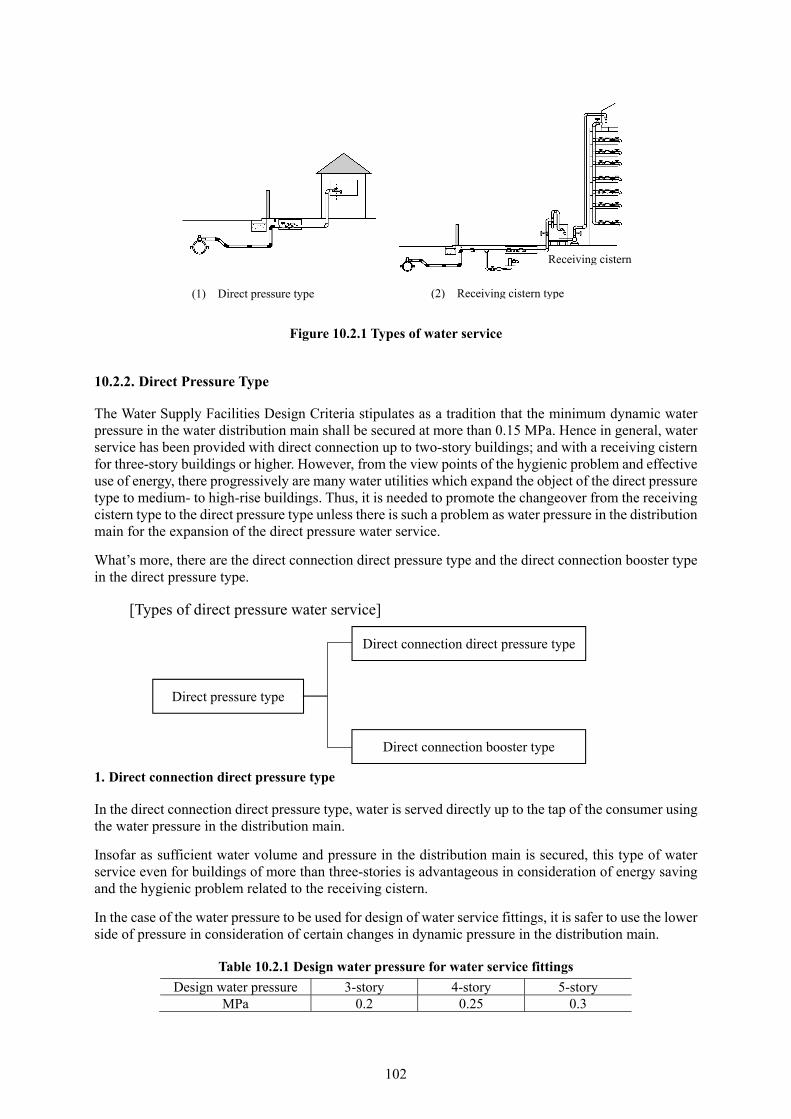
102
Figure 10.2.1 Types of water service
10.2.2. Direct Pressure Type
The Water Supply Facilities Design Criteria stipulates as a tradition that the minimum dynamic water pressure in the water distribution main shall be secured at more than 0.15 MPa. Hence in general, water service has been provided with direct connection up to two-story buildings; and with a receiving cistern for three-story buildings or higher. However, from the view points of the hygienic problem and effective use of energy, there progressively are many water utilities which expand the object of the direct pressure type to medium- to high-rise buildings. Thus, it is needed to promote the changeover from the receiving cistern type to the direct pressure type unless there is such a problem as water pressure in the distribution main for the expansion of the direct pressure water service.
What’s more, there are the direct connection direct pressure type and the direct connection booster type in the direct pressure type.
[Types of direct pressure water service]
1. Direct connection direct pressure type
In the direct connection direct pressure type, water is served directly up to the tap of the consumer using the water pressure in the distribution main.
Insofar as sufficient water volume and pressure in the distribution main is secured, this type of water service even for buildings of more than three-stories is advantageous in consideration of energy saving and the hygienic problem related to the receiving cistern.
In the case of the water pressure to be used for design of water service fittings, it is safer to use the lower side of pressure in consideration of certain changes in dynamic pressure in the distribution main.
Table 10.2.1 Design water pressure for water service fittings
Design water pressure 3-story 4-story 5-story MPa 0.2 0.25 0.3
Direct pressure type
Direct connection direct pressure type
Direct connection booster type
(1) Direct pressure type (2) Receiving cistern type
Receiving cistern

103
2. Direct connection booster type
The direct connection booster type is a type to serve water installing a direct connection booster type pump unit in the middle of the service pipe to boost the water pressure in the pipe.
Using this type, it makes possible the water service to medium- to high-rise buildings, to which water cannot be served by the direct connection direct pressure type, and, compared with the receiving cistern type, has effect of energy saving as the pressure in the distribution main is effectively used. In addition, with the type, space can be saved since no receiving cistern is needed, and such hygienic problem as cleaning can also be solved.
As types of water service to respective houses, there are the direct service type to directly pump water up to the tap; and the type to once pump water up to a tank placed on a high position (elevated tank) and supply water to the taps by gravity.
Since in the direct connection booster type the reverse pressure, when water service by the distribution main is shut down, is large, an effective check valve shall be installed close to the booster pump unit. As a check valve for this purpose, a pressure reduction type backflow preventer is generally used. --
10.2.3. Receiving Cistern Type
The receiving cistern type is a type once to receive water in a receiving cistern and serve, and possesses such merits that certain volume of water can be secured at the times of suspension of water service or a disaster, and that a large volume of water can be used at a time. On the other hand, it possesses sources of anxiety to users as such regular maintenance as inspection and cleaning is needed; the water temperature rises in summer and so forth.
Furthermore, the receiving cistern type shall be employed for water service for the following facilities, buildings etc.:
Facilities, buildings etc. which use a large volume of water at a time, and of which water use changes
largely, so there is a concern that such users bring about low water pressure in the distribution main.
Factories, businesses, laboratories etc. which handle, manufacture, process or store such dangerous
chemicals as poisons, hazardous substances, drugs etc.
Example: Facilities etc. which carry out such businesses as dry cleaning,, photography, printing and binding, petroleum handling, dying, plating etc.
Facilities which need certain amount of water service even at a time of suspension or reduction in water
service due to a disaster or an accident
Example: Such facilities as hospitals, hotels, department stores etc. and in case cooling water is to be fed to food freezers or computers etc.
1. Water service types in the receiving cistern type
Four types of water service are considered in the receiving cistern type, namely, the elevated tank type, the direct pumping type, the pressurized tank type and the stored pressure tank type.

104
[Types of receiving cistern type]
1) Elevated tank type
In this type, water is once received in a receiving cistern, pumped to the elevated tank on the rooftop, and served to each floor by gravity, and the type which has commonly been employed for a long time.
This type has such merits as a function to be always able to serve water in constant pressure, and possess certain stock of water. On the contrary, as the tank is situated on rooftop of the building, there are demerits in regard to appearance and sunlight. It is also its weak point that the water pressure on the floor right underneath the tank tends to be insufficient.
There is a fear that water in the elevated tank is polluted unless it is regularly cleaned as same as the receiving cistern.
2) Direct pumping type
In this type, water is once received in a receiving cistern and directly pumped to consumers’ taps, and water service is undertaken while the delivery pressure of pumping is kept constant by means of speed control of the motor.
Especially, in case water demand is small at night, water can be served without operating the pump with a provision of a pressurized tank (See Figure 10.2.2).
3) Pressurized tank type
In this type, water is once received in a receiving cistern, pumped to a pressurized tank to store in it, and delivered to the taps of the consumers. The system is operated in that the inside of the tank is always pressurized; the pump is activated as the pressure declines in accordance with the demand; the pressure gradually rises as the demand decreases; and the pump stops at last (See Figure 10.2.3).
Elevated tank type
Direct pumping type
Pressurized tank type
Stored pressure tank type
Receiving cistern type

105
Figure 10.2.2 Direct pumping type
Figure 10.2.3 Pressurized tank type
4) Stored pressure tank type
In this type, the inside of the steel tank is divided into a water chamber contained in a rubber bladder, which is highly air-tight, and a gas chamber. The inside of the bladder is the water chamber, and the space between the inside of the tank and the outside of the bladder is the gas chamber, and pressurized gas is enclosed in advance so that, when pump is operated, pressurized water is accommodated in the bladder.
The structural principle of this type is that the bladder slowly inflates as water is introduced in the water chamber; the gas is progressively compressed; and the pump stops as about half of the volume of the tank is filled with water and the pressure has reached to the prescribed value.
The stored pressure tank is mainly set on the rooftop of a building, and a riser pipe and a pump are connected (See Figure 10.2.4).
Figure 10.2.4 Stored pressure tank
Control panel
Pressure sensor
Delivery mouth
Flow switch
No. 1 Pump
No. 2 Pump Pressurized tank
Suction mouth
Delivery header Control panel
Flow switch No. 1 Pump
No. 3 Pump
Suction mouth
Pressurized tank
(Pump for a high-rise building)
Pressure sensor
Delivery mouth
Flow switch
No. 1 Pump
No. 2 PumpNo. 2 Pump
Control panel
Pressurized tank
Suction mouth
Air
Bladder
Water
Main body of tank
(1) Structure of the stored pressure tank (2) Stored pressure tank set on the rooftoppressure tank
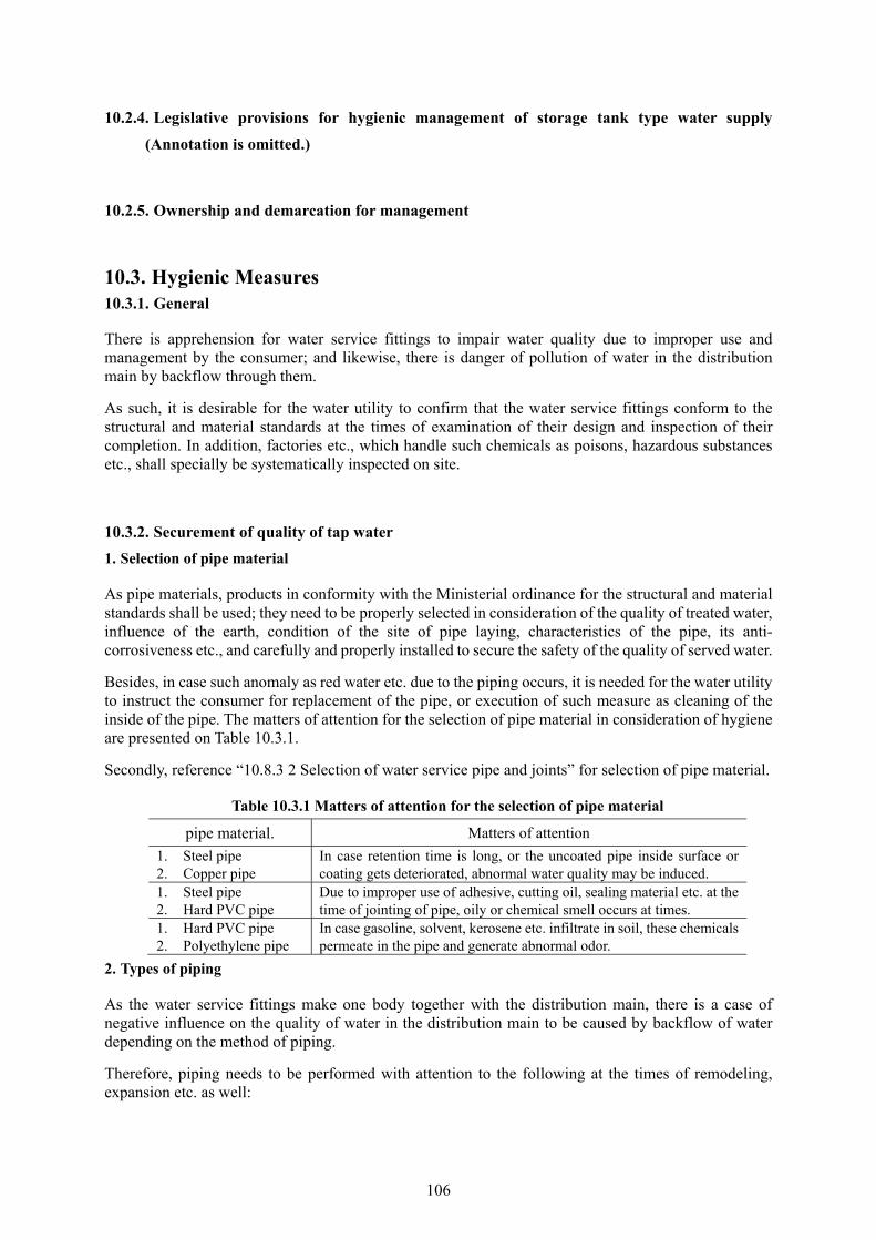
106
10.2.4. Legislative provisions for hygienic management of storage tank type water supply
(Annotation is omitted.)
10.2.5. Ownership and demarcation for management
10.3. Hygienic Measures 10.3.1. General
There is apprehension for water service fittings to impair water quality due to improper use and management by the consumer; and likewise, there is danger of pollution of water in the distribution main by backflow through them.
As such, it is desirable for the water utility to confirm that the water service fittings conform to the structural and material standards at the times of examination of their design and inspection of their completion. In addition, factories etc., which handle such chemicals as poisons, hazardous substances etc., shall specially be systematically inspected on site.
10.3.2. Securement of quality of tap water
1. Selection of pipe material
As pipe materials, products in conformity with the Ministerial ordinance for the structural and material standards shall be used; they need to be properly selected in consideration of the quality of treated water, influence of the earth, condition of the site of pipe laying, characteristics of the pipe, its anti-corrosiveness etc., and carefully and properly installed to secure the safety of the quality of served water.
Besides, in case such anomaly as red water etc. due to the piping occurs, it is needed for the water utility to instruct the consumer for replacement of the pipe, or execution of such measure as cleaning of the inside of the pipe. The matters of attention for the selection of pipe material in consideration of hygiene are presented on Table 10.3.1.
Secondly, reference “10.8.3 2 Selection of water service pipe and joints” for selection of pipe material.
Table 10.3.1 Matters of attention for the selection of pipe material
pipe material. Matters of attention
1. Steel pipe 2. Copper pipe
In case retention time is long, or the uncoated pipe inside surface or coating gets deteriorated, abnormal water quality may be induced.
1. Steel pipe 2. Hard PVC pipe
Due to improper use of adhesive, cutting oil, sealing material etc. at the time of jointing of pipe, oily or chemical smell occurs at times.
1. Hard PVC pipe 2. Polyethylene pipe
In case gasoline, solvent, kerosene etc. infiltrate in soil, these chemicals permeate in the pipe and generate abnormal odor.
2. Types of piping
As the water service fittings make one body together with the distribution main, there is a case of negative influence on the quality of water in the distribution main to be caused by backflow of water depending on the method of piping.
Therefore, piping needs to be performed with attention to the following at the times of remodeling, expansion etc. as well:
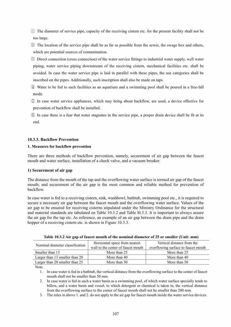
107
The diameter of service pipe, capacity of the receiving cistern etc. for the present facility shall not be
too large.
The location of the service pipe shall be as far as possible from the sewer, the swage box and others,
which are potential sources of contamination.
Direct connection (cross connection) of the water service fittings to industrial water supply, well water
piping, water service piping downstream of the receiving cistern, mechanical facilities etc. shall be
avoided. In case the water service pipe is laid in parallel with these pipes, the use categories shall be
inscribed on the pipes. Additionally, such inscription shall also be made on taps.
Water to be fed to such facilities as an aquarium and a swimming pool shall be poured in a free-fall
mode.
In case water service appliances, which may bring about backflow, are used, a device effective for
prevention of backflow shall be installed.
In case there is a fear that water stagnates in the service pipe, a proper drain device shall be fit at its
end.
10.3.3. Backflow Prevention
1. Measures for backflow prevention
There are three methods of backflow prevention, namely, securement of air gap between the faucet mouth and water surface, installation of a check valve, and a vacuum breaker.
1) Securement of air gap
The distance from the mouth of the tap and the overflowing water surface is termed air gap of the faucet mouth; and securement of the air gap is the most common and reliable method for prevention of backflow.
In case water is fed to a receiving cistern, sink, washbowl, bathtub, swimming pool etc., it is required to secure a necessary air gap between the faucet mouth and the overflowing water surface. Values of the air gap to be ensured for receiving cisterns stipulated under the Ministry Ordinance for the structural and material standards are tabulated on Table 10.3.2 and Table l0.3.3. It is important to always assure the air gap for the tap etc. As reference, an example of an air gap between the drain pipe and the drain hopper of a receiving cistern etc. is shown in Figure 10.3.3.
Table 10.3.2 Air gap of faucet mouth of the nominal diameter of 25 or smaller (Unit: mm)
Nominal diameter classification Horizontal space from nearest
wall to the center of faucet mouthVertical distance from the
overflowing surface to faucet mouthSmaller than 13 More than 25 More than 25 Larger than 13 smaller than 20 More than 40 More than 40 Larger than 20 smaller than 25 More than 50 More than 50 Note
1. In case water is fed in a bathtub, the vertical distance from the overflowing surface to the center of faucet mouth shall not be smaller than 50 mm.
2. In case water is fed in such a water basin as a swimming pool, of which water surface specially tends to billow, and a water basin and vessel, to which detergent or chemical is taken in, the vertical distance from the overflowing surface to the center of faucet mouth shall not be smaller than 200 mm.
3. The rules in above 1. and 2. do not apply to the air gap for faucet mouth inside the water service devices.

108
Table 10.3.3 Air gap for faucet mouth with nominal diameter of larger than 25 (Unit: mm)
Case Vertical distance from overflow level
to lowest position of faucet mouth
In case influence of neighboring wall is weak >1.7d’+5 mm
In case there is influence of neighboring wall
There is only one wall. <3d>3d, but <5d >5d
>3.0d’>2.0d’+ 5 mm >1.7d’+5 mm
There are two walls <4d>4d, but <6d >6d, but <7d >7d
>3.5d’>3.0d’ >2.0d’+5 mm >1.7d’+5 mm
Note 1. d: Inner diameter of faucet mouth (mm) d’: diameter of effective opening (mm) 2. In case the cross section of the mouth is rectangular, the long side is d. 3. In case there is a wall, which is higher than the overflow level, it shall be the neighboring wall. 4. In case feeding to a bath tab, vertical distance from overflow level to lowest position of faucet mouth
shall not be less than 50 mm. 5. In case such a water tank as swimming pool, where waves easily rise and a water tank or container, in
which detergents or chemicals are used in business activities, the vertical distance from the overflow level to the center of faucet mouth shall not be less than 200 mm.
6. The rules in above 4. and 5. do not apply to the air gap for faucet mouth inside the water service devices.
Figure 10.3.3 Example of air gap for drainage mouth of a receiving cistern etc.
2) Backflow prevention by a backflow preventing device
Although, as backflow preventing devices, there are the vacuum breaker (atmospheric type vacuum breakers), the check valves (See “10.8.4 4. Valves” for the types of valves.) etc., among them, the check valve brings about backflow at times due to deterioration because of aging. Therefore, although infallible means of backflow prevention is needed depending on the condition of its use, there is a method to secure an air gap, or set a water service device with a function of vacuum breaking at a proper place where backflow can be blocked.
Furthermore, regarding examples of places or conditions where is a fear of backflow due to vacuum, and preventive measures against backflow, see Table l0.3.4. Examples of places or conditions where is a fear of backflow and preventive measures against backflow.
In case a net is placed, the area excluding the net material shall be more than the cross section of the overflow pipe.
Note: D of the drain pipe is arbitrary.
But, H shall be more than 20 mm.
Overflow pie
Net Drain pipe

109
Table l0.3.4. Examples of places or conditions where is a fear of backflow and preventive
measures against backflow.
Condition Examples of places where is a fear of backflow
preventive measures against backflow.
In case air gap at faucet mouth is not secured
(1) Water service to bathtub, washing machine, dish washer etc. without sufficient air gap at faucet.
(2) Space from faucet mouth to overflowing level of receiving cistern or water tank used by various businesses is insufficient or splashing water touches the faucet.
Reference Annexed Table No. 2 & No. 3 of “Ministerial Ordinance for Structural and Material Standards”.
In case effective backflow prevention device or vacuum breaking device (atmospheric type vacuum breaker) is not fit.
(1)A vacuum breaking device (atmospheric type vacuum breaker) is not fit on flush valve of toilet bowl.
To install a vacuum breaking device (atmospheric type vacuum breaker)
(2)A backflow prevention device (check valve) is not fit on the outward discharging type non-freeze faucet
To install a check valve
In case function of such water service device as backflow prevention device or vacuum breaker(atmospheric type vacuum breaker) etc. get lowered due to aging etc.
(1)Maintenance of service device for prevention of backflow is improper.
To abide by management prescribed in the instruction for handling
(2)Decline in function and failure of water service device for backflow prevention due to aging
To do repair, replacement etc.
In case the tip of water service device is dipped in water
(1)The lawn faucet is submerged. To make the structure of faucet box water-tight so that rainwater does not intrude, or fit a backflow prevention device
(2)Fountain, from which bottom water eructs, and stone-made hand-wash basin at the shrine or temple
To provide a receiving cistern for the fountain, and keep adequate air gap at the faucet of the hand-wash basin.
(3)Wash tank, of which structure allows for water to be fed from the bottom and overflow from the top
To install a vacuum breaker (atmospheric type vacuum breaker)
In the case of inappropriate use of a hose
(1)The hose, which is connected to a faucet, is dipping in water
To be careful not to dip the tip of the hose, fit a vacuum breaker (atmospheric type vacuum breaker) on the faucet or install a check valve
(2)A bathtub boiler cleaner to be connected to the faucet for use or a device for bailing out water from a bathtub
In case the water service device does not bear necessary function
The balance between capacity of inhaling air of the vacuum breaker (atmospheric type vacuum breaker) and the nominal diameter of the faucet is inappropriate.
To replace the existing one with a proper vacuum breaker (atmospheric type vacuum breaker)
110
2. Prevention of a cross connection
It is prescribed in the structural and material standards that the water service pipe shall not be directly connected to a water pipe or other facility than the present water service fittings.
Since, as water is used for multi-purposes, pipes for other purposes are laid close to water service pipes, so it is not easy at times to identify them by their appearances, it is needed to make measures to prevent a cross connection such as inscriptions on the body of the pipes so that their uses can be identified.
10.4. Unusual Phenomena 10.4.1. General
Unusual phenomena are in general roughly divided into abnormal sound and vibration from water service fittings (those which are caused by water hammer and attrition etc. of parts of water service devices), and coloring and odor of tap water (those related to structure and material of water service fittings).
Abnormal sound and vibration in water service fittings are often removed by the improvement to be made in the form of piping and parts of water service devices. On the other hand, about coloring and odor of tap water, the phenomena need to carefully be observed to identify what the causes are. It is important to investigate their causes and quickly take proper steps after adequately explaining to the consumers.
10.4.2. Abnormal sound and vibration
In case abnormal sound and vibration in water service fittings are sensed, it is needed to immediately investigate the causes and take proper steps. If they are left over in such condition, the water distribution main etc. may be broken and leakage is induced at times.
The main causes and their remedies of abnormal sound and vibration from water service fittings are as presented on “Abnormal sound and vibration” on Table 10.4.1 Causes of abnormal phenomenon and measures against them.
10.4.3. Coloring and Odor of Tap Water
In case occurrence of coloring, turbidity, odor and taste of tap water is reported, the water utility immediately needs to investigate the cause and take proper steps. Additionally, if the water is judged to be unsuitable for drinking, the water service shall be suspended and so forth as required. At the time of investigation for the causes, the meters shall be dismantled and their strainers shall be examined if foreign matters are caught in them. In case there are any attached matters, identification of the matter shall be made, and, at the same time, it shall carefully be studied whether or not there are cases on the side of the distribution main as well. Provided the cause is judged to be attributable to the water service fittings, it is needed that such proper measure as restriction in their use etc. shall quickly be undertaken as measures for prevention of backflow into the distribution main.
10.4.4. Improvement Measures
As to measures in case the water utility receives consultation from consumers on abnormal phenomena, the situation shall adequately be identified, and at the same time their causes shall immediately be
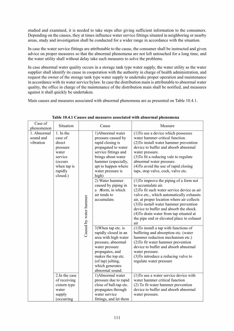
111
studied and examined, it is needed to take steps after giving sufficient information to the consumers. Depending on the causes, they at times influence water service fittings situated in neighboring or nearby areas, study and investigation shall be conducted for a wider range in accordance with the situation.
In case the water service fittings are attributable to the cause, the consumer shall be instructed and given advice on proper measures so that the abnormal phenomena are not left untouched for a long time, and the water utility shall without delay take such measures to solve the problems.
In case abnormal water quality occurs in a storage tank type water supply, the water utility as the water supplier shall identify its cause in cooperation with the authority in charge of health administration, and request the owner of the storage tank type water supply to undertake proper operation and maintenance in accordance with its water service bylaw. In case the distribution main is attributable to abnormal water quality, the office in charge of the maintenance of the distribution main shall be notified, and measures against it shall quickly be undertaken.
Main causes and measures associated with abnormal phenomena are as presented on Table 10.4.1.
Table 10.4.1 Causes and measures associated with abnormal phenomena
Case of phenomenon
Situation Cause Measure
1. Abnormal sound and vibration
1. In the case of direct pressure water service (occurs when tap is rapidly closed.)
Cau
sed
by w
ater
ham
mer
1)Abnormal water pressure caused by rapid closing is propagated to water service fittings and brings about water hammer (especially, apt to happen where water pressure is high)
(1)To use a device which possesses water hammer critical function. (2)To install water hammer prevention device to buffer and absorb abnormal water pressure. (3)To fit a reducing vale to regulate abnormal water pressure. (4)To avoid the use of rapid closing taps, stop valve, cock, valve etc.
2) Water hammer caused by piping in a πform, in which air tends to accumulate.
(1)To improve the piping of a form not to accumulate air. (2)To fit such water service device as air valve etc., which automatically exhausts air, at proper location where air collects (3)To install water hammer prevention device to buffer and absorb the shock. (4)To drain water from tap situated at the pipe end or elevated place to exhaust air
3)When tap etc. is rapidly closed in an area with high water pressure, abnormal water pressure propagates, and makes the top etc. (of tap) jolting, which generates abnormal sound.
(1)To install a tap with functions of buffering and absorption etc. (water hammer reduction mechanism etc.) (2)To fit water hammer prevention device to buffer and absorb abnormal water pressure. (3)To introduce a reducing valve to regulate water pressure
2.In the case of receiving cistern type water supply (occurring
1)Abnormal water pressure due to rapid close of ball-tap etc. propagates through water service fittings, and let them
(1)To use a water service device with water hammer critical function (2) To fit water hammer prevention device to buffer and absorb abnormal water pressure.

112
when ball-tap etc. opens and closes)
generate water hammer. 2)Water hammer caused by up-and-down action of float (open and close action) by billow of water due to discharging quantity
(1)In case water surface billows, to fit a water breaker on the water service device to receiving cistern. (2)To change the location of the discharging faucet. (3)To change to double port type, parent-child two-ball type, constant level valve etc. which possess relatively weak water hammer action.
3.Vibration and abnormal sound occur daily basis and chronically when opening and closing tap.
Due
to w
ear,
loos
ened
mou
ntin
g of
par
ts o
f w
ater
ser
vice
dev
ices
1)Top and gasket of facet, as they are worn out and make water pressure imbalanced, jolt and give abnormal sound.
(1)To change the top and gasket of faucet. Besides, in case, even if they are changed, abnormal sound does not disappear, it is desirable to change the faucet since the spindle is worn out. (2)As vibration and abnormal sound are apt to occur when water pressure is high, to install reducing valve or water hammer prevention device for buffer and absorbance.
2)As the riser pipe is not firmly fixed on the building, so pipe vibrates when tap is opened and closed, sound emits
(1)To prevent vibration, to firmly fix the riser pipe on the building with such device as grips or hooks at 1 to 2 m interval.
4.When booster pump starts, vibration or abnormal sound emits
Since anti-vibration measure at joint of pump and service pipe is insufficient, vibration and abnormal sound are generated.
(1) Flexible joints shall be fit at jointing points of pump and pipes at both upstream and downstream sides of pump so that vibration of pump is not transmitted to service pipe.
(2) In case minute vibration and solid sound propagate to the building, both anti-vibration pedestal and anti-vibration coupling shall be used..
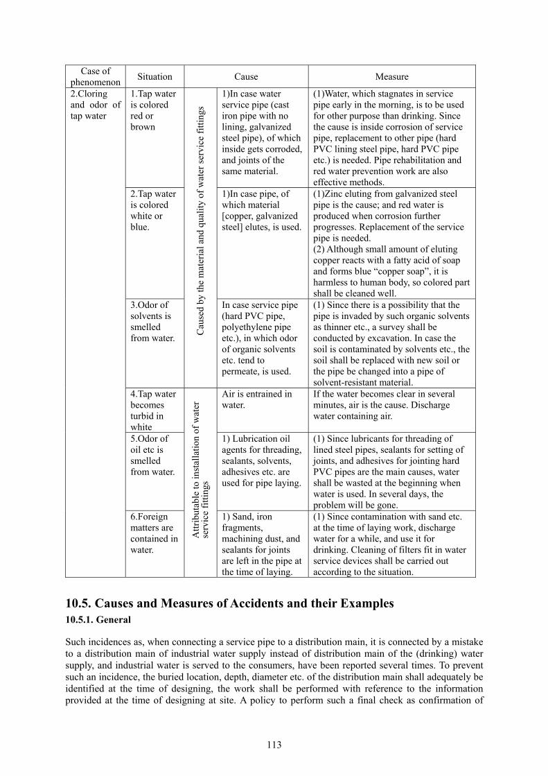
113
Case of phenomenon
Situation Cause Measure
2.Cloring and odor of tap water
1.Tap water is colored red or brown
Cau
sed
by th
e m
ater
ial a
nd q
uali
ty o
f w
ater
ser
vice
fit
ting
s
1)In case water service pipe (cast iron pipe with no lining, galvanized steel pipe), of which inside gets corroded, and joints of the same material.
(1)Water, which stagnates in service pipe early in the morning, is to be used for other purpose than drinking. Since the cause is inside corrosion of service pipe, replacement to other pipe (hard PVC lining steel pipe, hard PVC pipe etc.) is needed. Pipe rehabilitation and red water prevention work are also effective methods.
2.Tap water is colored white or blue.
1)In case pipe, of which material [copper, galvanized steel] elutes, is used.
(1)Zinc eluting from galvanized steel pipe is the cause; and red water is produced when corrosion further progresses. Replacement of the service pipe is needed. (2) Although small amount of eluting copper reacts with a fatty acid of soap and forms blue “copper soap”, it is harmless to human body, so colored part shall be cleaned well.
3.Odor of solvents is smelled from water.
In case service pipe (hard PVC pipe, polyethylene pipe etc.), in which odor of organic solvents etc. tend to permeate, is used.
(1) Since there is a possibility that the pipe is invaded by such organic solvents as thinner etc., a survey shall be conducted by excavation. In case the soil is contaminated by solvents etc., the soil shall be replaced with new soil or the pipe be changed into a pipe of solvent-resistant material.
4.Tap water becomes turbid in white
Att
ribu
tabl
e to
inst
alla
tion
of
wat
er
serv
ice
fitt
ings
Air is entrained in water.
If the water becomes clear in several minutes, air is the cause. Discharge water containing air.
5.Odor of oil etc is smelled from water.
1) Lubrication oil agents for threading, sealants, solvents, adhesives etc. are used for pipe laying.
(1) Since lubricants for threading of lined steel pipes, sealants for setting of joints, and adhesives for jointing hard PVC pipes are the main causes, water shall be wasted at the beginning when water is used. In several days, the problem will be gone.
6.Foreign matters are contained in water.
1) Sand, iron fragments, machining dust, and sealants for joints are left in the pipe at the time of laying.
(1) Since contamination with sand etc. at the time of laying work, discharge water for a while, and use it for drinking. Cleaning of filters fit in water service devices shall be carried out according to the situation.
10.5. Causes and Measures of Accidents and their Examples 10.5.1. General
Such incidences as, when connecting a service pipe to a distribution main, it is connected by a mistake to a distribution main of industrial water supply instead of distribution main of the (drinking) water supply, and industrial water is served to the consumers, have been reported several times. To prevent such an incidence, the buried location, depth, diameter etc. of the distribution main shall adequately be identified at the time of designing, the work shall be performed with reference to the information provided at the time of designing at site. A policy to perform such a final check as confirmation of
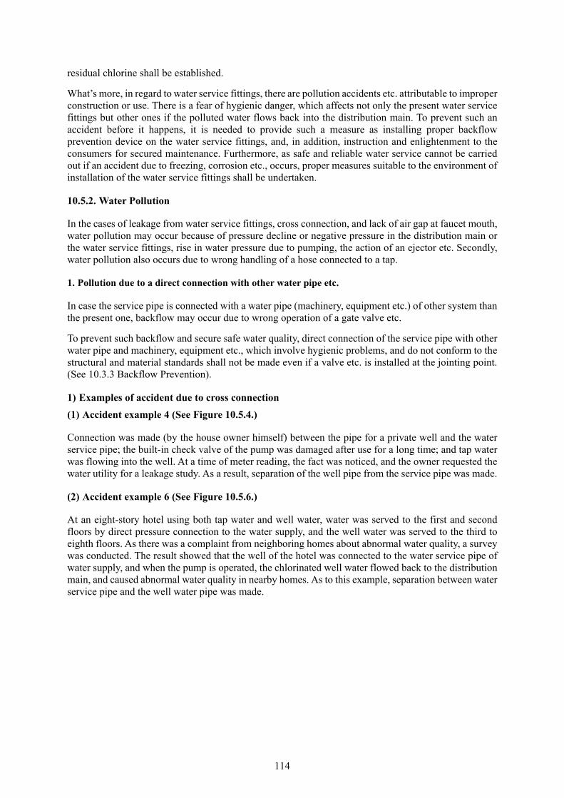
114
residual chlorine shall be established.
What’s more, in regard to water service fittings, there are pollution accidents etc. attributable to improper construction or use. There is a fear of hygienic danger, which affects not only the present water service fittings but other ones if the polluted water flows back into the distribution main. To prevent such an accident before it happens, it is needed to provide such a measure as installing proper backflow prevention device on the water service fittings, and, in addition, instruction and enlightenment to the consumers for secured maintenance. Furthermore, as safe and reliable water service cannot be carried out if an accident due to freezing, corrosion etc., occurs, proper measures suitable to the environment of installation of the water service fittings shall be undertaken.
10.5.2. Water Pollution
In the cases of leakage from water service fittings, cross connection, and lack of air gap at faucet mouth, water pollution may occur because of pressure decline or negative pressure in the distribution main or the water service fittings, rise in water pressure due to pumping, the action of an ejector etc. Secondly, water pollution also occurs due to wrong handling of a hose connected to a tap.
1. Pollution due to a direct connection with other water pipe etc.
In case the service pipe is connected with a water pipe (machinery, equipment etc.) of other system than the present one, backflow may occur due to wrong operation of a gate valve etc.
To prevent such backflow and secure safe water quality, direct connection of the service pipe with other water pipe and machinery, equipment etc., which involve hygienic problems, and do not conform to the structural and material standards shall not be made even if a valve etc. is installed at the jointing point. (See 10.3.3 Backflow Prevention).
1) Examples of accident due to cross connection
(1) Accident example 4 (See Figure 10.5.4.)
Connection was made (by the house owner himself) between the pipe for a private well and the water service pipe; the built-in check valve of the pump was damaged after use for a long time; and tap water was flowing into the well. At a time of meter reading, the fact was noticed, and the owner requested the water utility for a leakage study. As a result, separation of the well pipe from the service pipe was made.
(2) Accident example 6 (See Figure 10.5.6.)
At an eight-story hotel using both tap water and well water, water was served to the first and second floors by direct pressure connection to the water supply, and the well water was served to the third to eighth floors. As there was a complaint from neighboring homes about abnormal water quality, a survey was conducted. The result showed that the well of the hotel was connected to the water service pipe of water supply, and when the pump is operated, the chlorinated well water flowed back to the distribution main, and caused abnormal water quality in nearby homes. As to this example, separation between water service pipe and the well water pipe was made.
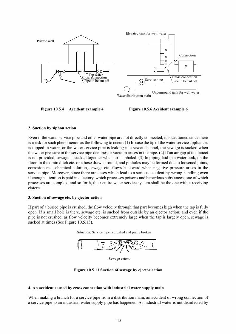
115
Figure 10.5.4 Accident example 4 Figure 10.5.6 Accident example 6
2. Suction by siphon action
Even if the water service pipe and other water pipe are not directly connected, it is cautioned since there is a risk for such phenomenon as the following to occur: (1) In case the tip of the water service appliances is dipped in water, or the water service pipe is leaking in a sewer channel, the sewage is sucked when the water pressure in the service pipe declines or vacuum arises in the pipe. (2) If an air gap at the faucet is not provided, sewage is sucked together when air is inhaled. (3) In piping laid in a water tank, on the floor, in the drain ditch etc. or a hose drawn around, and pinholes may be formed due to loosened joints, corrosion etc., chemical solution, sewage etc. flows backward when negative pressure arises in the service pipe. Moreover, since there are cases which lead to a serious accident by wrong handling even if enough attention is paid in a factory, which processes poisons and hazardous substances, one of which processes are complex, and so forth, their entire water service system shall be the one with a receiving cistern.
3. Suction of sewage etc. by ejector action
If part of a buried pipe is crushed, the flow velocity through that part becomes high when the tap is fully open. If a small hole is there, sewage etc. is sucked from outside by an ejector action; and even if the pipe is not crushed, as flow velocity becomes extremely large when the tap is largely open, sewage is sucked at times (See Figure 10.5.13).
Figure 10.5.13 Suction of sewage by ejector action
4. An accident caused by cross connection with industrial water supply main
When making a branch for a service pipe from a distribution main, an accident of wrong connection of a service pipe to an industrial water supply pipe has happened. As industrial water is not disinfected by
Private well
Cross connection Tap water
Pipe to be cut off
Elevated tank for well water
Water distribution main
Service pipe
Connection
Cross connection Pipe to be cut off
Underground tank for well water
Situation: Service pipe is crushed and partly broken
Sewage enters.
116
chlorine, and is highly unlikely to conform to the water quality standards of tap water, there is a fear for it to cause such health hazards as diarrhea and stomach ache depending on an occasion.
To prevent an accident by such a cross connection, residual chlorine shall be confirmed and tested after management of drawings and completion of construction, and take such measures as to be able to distinguish the water supply main for drinking from the industrial water supply main.
10.5.3. Accidents Accompanying Abnormal Phenomenon and Other Accidents
As an abnormal phenomenon of water service fittings, there are abnormal vibration and noise caused by water hammer which is rapid and transient pressure surge occurring in the pipe. Water hammer occurs where (1) rapidly opening and closing cocks or valves are used; (2) Water pressure in the pipe is high; and (3) Flow velocity in the pipe is high. As to abnormal phenomena, reference Table 10.4.1 Causes and measures accompanying abnormal phenomena.
1. Accidents caused by water hammer
Many of accidents of water hammer occur in the receiving cistern. Its causes are malfunction of the constant level valve of the cistern, defective ball tap, and scintillation of the ball by waves due to lack of a water breaking board causing repetition of rapid opening and shutting of the valve. Moreover, as the causes of water hammer attributable to water service appliances, there are many cases of wear of the top, gasket etc. of the faucet, and amplified vibration of the pipe brought about by rapid opening and shutting of the faucet (single-lever).
10.5.4. Freezing (Annotation is omitted.)
10.5.5. Deterioration
Since corrosion of metal service pipes, joints etc. is a cause of reduced spout, red water, leakage, adequate attention needs to be paid to prevention of corrosion.
Corrosion is a phenomenon of metal to be chemically eroded under certain environmental condition, and classified into wet corrosion and dry corrosion. Corrosion of metal pipe in the earth is wet corrosion, which occurs electrochemically with the presence of water. As wet corrosion, there are electric corrosion caused by stray current, and natural corrosion by the formation of a corrosion cell without influence of stray current. Classification of corrosion is illustrated in Figure 10.5.22.
On the other hand, physical and chemical characteristics of non-metal pipes deteriorate by ageing. Accordingly, adequately understanding the environment of water service fittings installation, a pipe material, which withstands such environment, shall be selected, and measures for prevention of corrosion and deterioration of material shall be undertaken.
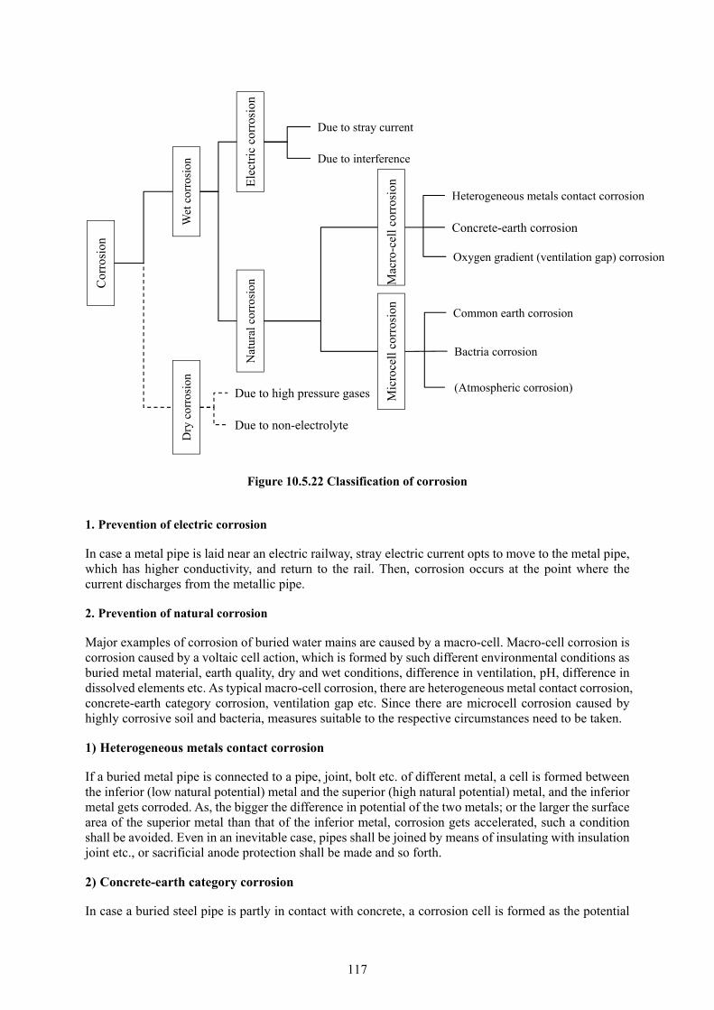
117
Figure 10.5.22 Classification of corrosion
1. Prevention of electric corrosion
In case a metal pipe is laid near an electric railway, stray electric current opts to move to the metal pipe, which has higher conductivity, and return to the rail. Then, corrosion occurs at the point where the current discharges from the metallic pipe.
2. Prevention of natural corrosion
Major examples of corrosion of buried water mains are caused by a macro-cell. Macro-cell corrosion is corrosion caused by a voltaic cell action, which is formed by such different environmental conditions as buried metal material, earth quality, dry and wet conditions, difference in ventilation, pH, difference in dissolved elements etc. As typical macro-cell corrosion, there are heterogeneous metal contact corrosion, concrete-earth category corrosion, ventilation gap etc. Since there are microcell corrosion caused by highly corrosive soil and bacteria, measures suitable to the respective circumstances need to be taken.
1) Heterogeneous metals contact corrosion
If a buried metal pipe is connected to a pipe, joint, bolt etc. of different metal, a cell is formed between the inferior (low natural potential) metal and the superior (high natural potential) metal, and the inferior metal gets corroded. As, the bigger the difference in potential of the two metals; or the larger the surface area of the superior metal than that of the inferior metal, corrosion gets accelerated, such a condition shall be avoided. Even in an inevitable case, pipes shall be joined by means of insulating with insulation joint etc., or sacrificial anode protection shall be made and so forth.
2) Concrete-earth category corrosion
In case a buried steel pipe is partly in contact with concrete, a corrosion cell is formed as the potential
Cor
rosi
on
Wet
cor
rosi
on
Ele
ctri
c co
rros
ion
Due to stray current
Due to interference
Nat
ural
cor
rosi
on
Dry
cor
rosi
on
Mac
ro-c
ell c
orro
sion
M
icro
cell
corr
osio
n
Heterogeneous metals contact corrosion
Concrete-earth corrosion
Oxygen gradient (ventilation gap) corrosion
Common earth corrosion
Bactria corrosion
(Atmospheric corrosion) Due to high pressure gases
Due to non-electrolyte
118
of the portion of the pipe in contact with alkaline concrete becomes higher than the other portion, and the letter is corroded. Likewise, in case a steel pipe, penetrating concrete foundation of a structure, is contact with reinforcing bars, corrosion is accelerated. To prevent such influx and outflow of electric current due to such a contact, pipes coated with powder polyethylene shall be used; or they shall be wrapped with anti-corrosive tape.
3) Ventilation gap corrosion
If a pipe is laid in soil with good ventilation and one with poor ventilation in series, a corrosion cell is formed due to different environments and the portion with lower potential is corroded. In addition to this, there are ones caused by difference in depths of burial, difference in moisture, and the one caused by an isolating object laid on the ground, which makes difference in ventilation. Corrosion prevention shall be in conformity with the prevention of earth category corrosion.
10.6. Installation and Construction Management of Water Service Fittings
The installation of water service fittings stands for construction of setting up or alteration of water service fittings, and includes all their new installation, reform, repair and demolition. Besides, the construction includes the processes of study, planning, installation and inspection.
10.6.1. Types of Construction
1) New installation
This denotes the new construction of water service fittings.
2) Reform work
This means the construction to change the original form of water service fittings such as enlargement of the diameter of service pipe, change in pipe material, furnishing of additional taps etc.
What’s more, reform construction includes reform, which is carried out by the consumer in the occasion of rebuilding or expansion of his house, and in addition, construction to change the location of branching from the distribution main or replacement of the service pipe etc., and change in the location of the meter when distribution mains are newly laid or moved as the work which is required by the water utility for its business operation.
3) Repair work
This denotes repair work of localized damage of a service pipe, tap etc. which does not change the original form of water service fittings.
4) Demolition work
This means demolition of water service fittings from the distribution main or branching point on the other water service fittings.
10.6.2. Reform Work
Water service fittings are installed in adequate consideration of their functions, strength and durability. However, as deterioration due to aging progresses, or taps increase in number, reduction in spout and decline in service capacity occur, improvement in the water service fittings, or movement of their branching point become necessary.
119
1. Reduction in spout
Of reasons for reduction in water spout, ones related to water service fittings are as follows:
Too small diameter of the service pipe as to water consumption
Insufficient water pressure
Too many corporation taps branching from a distribution main
Reduction in cross-sectional area of the serve pipe due to rusting
To deal with such reasons, such measures as the followings shall be taken:
1) Too small pipe diameter and insufficient water pressure
In case more taps are fit on one service pipe than initially designed, the pipe diameter becomes to be too small in regard to the necessary consumption. The service pipe needs to be reformed with a pipe of proper diameter in such a case.
Likewise, in case spout of water has become poor in an almost entire block of a service area, it is presumed that the water pressure of distribution main is low. In such a case, improvement of the distribution mains network is required.
2) Such scale as rusting in the pipe
Water service fittings, for which galvanized steel pipe is used, the sectional area of the pipe becomes small if rusting occurs in the pipe resulting in the reduction in water spout. Drastic solution is the replacement of the pipe in such a case.
3) Others
If water service is suspended due to construction of distribution mains, water spout is reduced as a
result of the strainer of the meter clogged with the scale when water service is resumed.
In case water is leaking in the ground, or the spout of water is insufficient due to a trouble of such water
service device as the curb cock, the site shall be surveyed to identify its cause, and a proper measure needs
to be taken.
2. Replacement of corporation tapping for service pipe
Replacement of corporation tapping for service pipe is carried out mainly when the distribution main is replaced. If superannuated or broken service pipes are found, they shall be replaced at the same time from the viewpoint of the prevention of a collateral disaster. Additionally, in the case of lead pipe, it must be replaced.
10.6.3. Repair work
Since leakage from water service fittings is loss of precious water resources, and may bring about a collateral disaster, its monitoring and repair are important work of operation and maintenance. Types of leakage from water service fittings are classified by their location of occurrence into outdoor leakage and indoor leakage, and their system of repair work is as follows:
120
1. Types of leakage
1) Outdoor leakage
The majority of outdoor leakage is the one from the corporation cock and the service pipe buried in the road downstream of the corporation cock. In fact, finding leakage in the road is difficult as almost all roads are paved. What’s more, since it is possible that prolonged leakage may induce a cave-in accident of the road, and develop to bring about an accident of the distribution main, efforts need to be made to find the leakage early in consideration to respective damage such as influence to the consumers etc. As its measure, systematic leakage survey by means of leakage detectors etc. in the area where many leakages are occurring is effective.
Since there are many cases of leakage due to damage to the distribution main and the service pipe caused by excavation work of other enterprises, guidance, patrol etc. to them shall positively be conducted.
2) Indoor leakage
Of indoor leakage, that of high frequency of occurrence is the one due to the degradation in the gasket of the tap. As this type of leakage is within the simple repair work, and the consumer can easily repair, it is needed to promote its repair method to the public.
2. System of repair work
As to the system of repair work, it is needed to establish an emergency repair system with consideration to the number of repairs, the details of repair etc. Especially, since the repair system for leakage in the road needs to be established by the water utility in consideration of the prevention of a collateral disaster including at night and a holiday. It is also effective to fit a stop valve, with which the consumer can easily operate, before or after the meter to minimize the discharging water caused by an accident occurring between the meter and the tap.
There is a tendency for the consumer to be indifferent about leakage upstream of the meter as the leakage is not metered, so it tends to be a long time until it is repaired. Thus, it is also needed for the water utility to extend its scope of responsibility for leakage repair up to inside the premises of the house.
10.6.4. Demolition Work (Annotation is omitted.)
10.6.5. Installation by the Designated Water Service Fittings Installer (Annotation is omitted.)
10.6.6. Management of Installation of Water Service Fittings
1. Management of the materials
Since the service pipe and water service devices used for the installation of water service fittings directly come into contact with tap water, the location for their storage shall be selected to be a place which is hygienically safe and protected from rain and wind.
2. Management of installation of water service fittings in the road
Installation of water service fittings is the construction work from the corporation cock to water service devices at the end of the water service fittings, and undertaken on the burden by the consumer. Above all, since the work of branching from the distribution main is construction in the road, proper process control, quality control and safety management are required. In addition, while adequately understanding the structural and material standards, the water service bylaws etc., the work shall be

121
carried out under the direction of the water utility.
Common points for attention related to the installation of water service fittings are given below:
1) Process control
Always understanding the progress of the work and comparing the progress with the prearranged schedule, smooth progress of the work shall be aimed.
2) Management of the work
Prior to the work, proper management of the work shall be conducted based on the work plan, for which
coordination with the water utility has been made.
Advanced consultation with the water utility and related enterprises shall be made on the announcement
of water service suspension, replacement of water mains, such other item as the section, for which the
time for the work is specially predetermined, smooth implementation of the work processes within the
prescribed time shall be aimed.
3) Confirmation of the work
Such a proper measure as presentation of necessary data, reports etc. shall be taken so that the water utility can always confirm the situation of the work.
4) Briefing to residents in the neighborhood of the site
Prior to the work, efforts shall be made to give briefing to residents in the neighborhood of the site on the specific details of the work so that their sufficient cooperation to the implementation of the work can be obtained.
Moreover, necessary public relations shall be conducted using a bulletin board etc. to notify residents in the neighborhood of the site and pedestrians of the details of the work.
5) Handling of impediments
In case movement, protection, detouring of buried objects, underground facilities and other structures under administration of other entity are needed, the water utility and the administrator of the buried object shall immediately be reported so that their instruction is given.
6) Prevention of a disaster on the public
During the implementation of the work, related laws and regulations shall be abided by so that the safety of the residents etc. is assured. In addition, adequate attention shall be paid so as not to cause obstacles to such facilities as structures, roads etc., and, at the same time, proper measures need to be undertaken so that claims from residents about noise, vibration, dust etc. do not arise.
7) Emergency response
In case an accident occurs or there is a fear of occurrence of an accident, while necessary measure is immediately taken, the situation of the accident and the details of the measure shall be reported to the water utility and related authorities.
3. Management of installation of water service fittings in the premises of the house
Installation of water service fittings in the premises of the house in general denotes the construction of fittings from the meter down to the terminal water service devices, and is carried out by the request of the consumer. Coordination with other architectural contractors etc. may at times be required depending

122
on the contents of the work. Installation of water service fittings in the premises of the house shall be implemented in consideration of these points, and it is necessary to undertake process control, quality control, and safety management based on adequate understanding of laws and regulations related to the structural and material standards.
10.6.7. Observation and Inspection
Following observation and inspection shall be conducted by the water utility when water service fittings are installed:
1. Observation of the work
Of installation of water service fittings, for the work in the road, it is desirable to observe the work including an observation without notice in consideration of confirmation of proper implementation of the work and future operation and maintenance.
2. Water pressure test
In the case of new installation, it is desirable to undertake a water pressure test, under which test water pressure of 1.75 MPa is held for 1 min., so as to confirm if piping and jointing have firmly been carried out from the assurance of proper work point of view.
Items of attention related to water pressure test are as follows:
To discharge air in water service fittings
The speed of filling water shall be as slow as possible to confirm the status of exhaust of air.
The speed of raising water pressure shall be gradual so as not to cause water hammer.
The pressure gauge shall be fit in the lowest point in the service pipe.
3. Inspection of the work
Completed water service fittings shall mainly be inspected for the following items if they are in conformity with the structural and material standards based on the construction standards prescribed by the water utility while checking respective parts of the fittings with the as-built drawings:
To confirm the status of the installation work in terms of pipe material, diameter, length of pipe laying
and depth of burial. Especially, the situation of pipe laying in the public road shall be inspected with the
pictures of the construction site.
The status of installation of the water service device for backflow prevention and the air gap between
the spout of the faucet and the overflowing water surface
The status of installation of the meter including whether or not its direction is correct.
Existence of cross-connections and direct connection to a pump
4. Confirmation of functions
As function test after start of water service, confirmation shall be made if the meter is functioning when a tap is opened, on the status of spouting from water service devices, on their working condition etc.
5. Confirmation of residual chlorine
It shall be confirmed whether or not the residual chlorine in water sampled from the tap is in conformity with the water quality standards. Unless residual chlorine is detected in the prescribed concentration,

123
the water service fittings shall be cleaned with water from the distribution main until residual chlorine is detected. In case, despite of such an operation, residual chlorine is not detected, confirmation shall be made on residual chlorine in the distribution main, and whether or not the fittings is connected to other system than water supply.
10.6.8. Application for exclusive occupation and excavation (Annotation is omitted.)
10.6.9. Collection of Information on Water Mains
Of installation of water service fittings, the work to excavate the road and the corporation tap on a distribution main for branching is undertaken in pretty large a number of times a year, and about 90% of leakage in the road is attributable to leakage from service pipes. Since the distribution main is at times exposed when tapping for branching or repair of leakage is carried out, data on earth cover of the distribution main, distance from the roadside ditch, type of quality of surrounding earth, status of corrosion of outside pipe wall etc. shall be classified and stored in a computer etc. as information related to the water main. Such information related to the water main will make a very useful asset as data in aid at the time of replacement of the water mains. The water utility, which has introduced a mapping system, can use and manage such information as attributable data of mapping.
10.7. Pipe laying 10.7.1. Items of attention related to pipe laying
The service pipe is laid in the ground in the public road, private road or a house lot in a case; or laid inside a building or, exceptionally, laid outside exposed in another case.
Consideration is required to select water service fittings suitable to the location of installation; provide a piping shaft inside a building so as to easily carry out such maintenance as repair or replacement; or lay in the ground in the house lot avoiding piping under the floor and so forth.
After completion of the work, to judge the propriety of the work, the existence of leakage from the joints etc. shall be confirmed imposing testing pressure by a test pump.
1. Pipe laying in the ground
Items of attention related to pipe laying in the ground are as follows:
1) To secure the earth cover prescribed by the public road, private road, house lot etc., and, at the same
time, apply polyethylene sleeves to protect galvanized steel pipe and cast iron pipe, or use pipe with
anti-corrosive coating.
2) In case pipe laying is made crossing a road, the pipe shall be laid perpendicularly to the road, and the
stop valve shall be placed inside the house lot rather than in the road in consideration of ordinary
maintenance.
3) In case plastic pipe (hard PVC pipe, polyethylene pipe etc.) is used for pipe laying in the ground, the
pipe may be swollen and softened causing obnoxious odor or leakage if it comes in contact with such
chemicals as an organic solvent (Xylene, toluene etc.) used for preparation, dilution, cleaning of
paints for repainting of outside walls; kerosene stored in a fuel tank set in house lot, leaking and
permeating in the ground; or creosote applied as a preservative for the foundation. It is cautioned that
the pesticide used for termites, which is sprayed on the foundation of a house etc., may cause the

124
same effects.
Especially, at a chemical factory, research institute, gas station etc, where a large quantity of organic solvents are used, and in the ground containing substances, which adversely affect the pipe material, metal pipe shall be used instead of plastic pipe. In case plastic pipe is inevitably used, they shall be protected by a sheath pipe.
4) At such a location as the section where the buried pipe is led to the building; an open ditch, where
the pipe is crossing; a place of weak ground where there is a fear of uneven subsidence, expansion
and flexible joints, which possess flexibility and extensibility, shall be used, or piping by the use of
combination of elbows shall be made so that the absorption of stress by external forces shall be taken
into consideration.
5) After the installation of the service pipe, a large garden rock, and plant, and a concrete structure are
at times placed on the pipe when constructing a garden or garage. In such a case, as repair and
replacement work becomes difficult, the pipe shall be moved to a location where no trouble is caused.
2. Piping inside the building
Items of attention related to pipe laying inside the building are as follows:
1) It is cautioned that, in case plastic pipe is used, if it comes in contact with a foundation or joist to
which creosote is applied as a preservative, the same phenomenon as that mentioned in the preceding
clause 3) as the case of buried plastic pipe may occur.
2) As for hard PVC pipe constructed with an adhesive for joining, water shall be washed with water or
apply sufficient ventilation to exhaust the vapor of the adhesive.
3) When laying polyethylene pipe, of which linear expansion coefficient is large, meandering pipe
laying etc. shall be made in consideration of expansion and contraction. Besides, the bending radius
of the pipe shall be more than 20 times the pipe diameter in the case of the class 1 (soft) pipe, and
more than 30 times in the case of the class 2 (hard) pipe.
4) Although it is desirable for service pipe to be laid in the shortest route, pipe laying under the floor
shall be avoided as maintenance work is hindered.
5) In case pipe laying is made through a wall of a building, such a preventive measure as a piping sleeve
shall be provided where the pipe penetrates the wall to prevent damage to the pipe.
6) Where water pressure in the pipe is high, rapid opening and closing faucets or valves etc. are used,
or water column separation opts to occur, there is a fear of water hammer to happen. A water hammer
prevention device shall be fit in such a location.
7) Consideration shall be given in that water service fittings can be repaired, replaced and so forth
without breaking the building when they become superannuated, pipe shafts or piping trench shall be
provided avoiding the burial of pipe in the concrete. In this case, the following points shall be taken
into consideration:
Sufficient space shall be provided in the pipe shaft so that the work of inspection, repair or reform is
not interfered.
In case the length of the pipe in the shaft is large, the shaft shall be fixed on the building at a proper
125
interval to prevent deflection or swaying.
In a cold region, the shaft shall be so structured that such openings as inspection hand-holes on it can
tightly be closed so that cold air does not pass through the shaft.
The pipe in the shaft shall be covered with glass-fiber wool, polyethylene foam etc. to prevent damage
caused by freeze or other causes.
Pipes shall be labeled with names of the uses of the pipes such as water supply, gas, sewage etc. on
their coated pipe surface, and the directions of flow shall also be clearly indicated by arrows.
As for water service and hot water service pipes, a fear about water pressure and complication
associated with construction can be eliminated with the adoption of a sheath header system. Also at the
time of water leakage or replacement of the pipe due to aging, repair or construction work can be carried
out without breaking the body or the interior of the building. Cross-linked polyethylene pipe and
polybutene pipe are mainly used for the sheath header method.
10.7.2. Prevention and Management of Risk
Measures for prevention of risk to be considered are as follows:
1) If a service pipe is laid through a sewage tank or a wastewater tank, as there is possibility for dirty
water to enter the pipe, the pipe shall be laid by-passing such a facility as a wastewater tank.
2) The air gap between the spout of the tap and the influent pipe of dilution water of the septic tank shall
be more than 50 mm.
10.7.3. Return and Designation of the Certificate of Chief Engineer for Installation of Water
Service Fittings (Annotation is omitted.)
10.7.4. Refurbishment of Water Service Fittings
Galvanized steel pipe or even steel pipe with anti-corrosive inner coating, for which piping resin coated joints are used, gets rusty and causes red water or reduced water conveyance due to exfoliation of resin coating etc. Although its drastic solution is to replace the service pipe, since the cost of pipe replacement in the building with a receiving cistern is costly due to such property of the water service facility as the existence of hidden section of the pipeline, pipe rehabilitation is implemented in many cases.
As rehabilitation work, although there are the lining method, the magnetic method, the deaeration method, the electron anti-rust method, the calcium method etc., the lining method with the application of resin family paint is used in many cases.
10.8. Water Service Pipe, Joints and Water Service Devices 10.8.1. General
Since it is extremely important for the consumer himself to carefully watch the water service fittings and properly maintain them, the makers of service pipe, joints and water service devices, designated
126
installers of water service fittings, water utilities etc. need to positively give information to the consumers on maintenance of the fittings.
10.8.2. Manner of Operation and Maintenance
To prevent an accident of backflow which adversely affect the health of man, proper measures are needed, and, specifically speaking, maintenance by means of ad hoc or regular inspection of water service devices etc. is an effective step.
10.8.3. Water Service Pipe and Joints
1. Types of water service pipe and joints
As types of water service pipe, there are the steel pipe, the stainless steel pipe, the hard PVC pipe, the polyethylene pipe, the copper pipe etc. Characteristics of water service pipe by its category are tabulated on Table 10.8.3.

127
Table 10.8.3 Characteristics of water service pipe
Pipe material Merits Demerits Steel pipe - Hard PVC lining steel pipe - Polyethylene powder lining steel pipe - Heat-resistant hard PVC lining steel pipe
- Strength is large, possessing durability - Workability is high. - There is rich variety in types of lining, so a pipe material can be chosen depending on status of piping and condition of the use.
- Consideration is needed to electric corrosion. - If the inside and outside anti-corrosion coating is damaged, it is easily corroded.
Stainless steel pipe -Excellent in corrosion resistance, so no need for lining or coating. -Strength is large, and durable. -Weight is light, and workability is high. -Corrugated stainless steel pipe, which has good seismic resistance and workability, is available.
- Insulation is needed between stainless steel and other metal material. - Careful handling is required not to make a cut or scratch on the pipe.
Hard PVC pipe -Excellent in corrosion resistance and electric corrosion resistance - Pipe material of shock resistance and heat-resistance is also available. - Weight is light, and workability is high. - Workability is good. -Inside roughness does not change. - As the rubber gasket type joints have ability of expansion and flexibility, the pipe can follow the movements of the soil.
-Anti-impact property is lowered in low temperature. - Vulnerable to organic solvents, heat and UV. - If getting cuts on its surface, the strength reduces.
Polyethylene pipe -Flexibility, shock resistance, freeze resistance are high. - Excellent in corrosion resistance and electric corrosion resistance - As weight is light, flexibility is high, and the product is of long piece, its workability is good.- Workability is good. -Inside roughness does not change.
-Vulnerable to heat. - Caution is needed to permeation of organic solvents, gasoline etc. - Careful handling is required as it easily get injured.
Copper pipe - Excellent in corrosion resistance - Weight is light, and workability is high. -Inside roughness does not change. - Coated pipe is also available to prevent injury on body and earth-related corrosion. - There are the soft pipe (mainly for laying in the ground) and hard pipe (for indoor laying).
- Since pipe wall is thin, careful handling is needed not to make a dent etc. on pipe body
Cross-linked polyethylene pipe
-Excellent in heat resistance, corrosion resistance and electric corrosion resistance - As weight is light, flexibility is high, and the product is of long piece, its workability is good.-Inside roughness does not change. - Used as sheath header type water service pipe and hot water service pipe.
-Vulnerable to UV and organic solvents. - Careful pipe laying is required since there is a fear of thermal expansion and burst.
Polybutene pipe -Excellent in heat resistance and corrosion resistance - As weight is light, flexibility is high, and the product is of long piece, its workability is good.-Inside roughness does not change. - Used as sheath header type water service pipe and hot water service pipe.
- Careful pipe laying is required since there is a fear of thermal expansion and burst.

128
2. Selection of water service pipe and joints
When selecting water service pipe and joints, it is needed to consider water quality, water pressure in the pipe, soil around the pipe, location of laying etc. However, as to service pipe and joints used for water service fittings between the branching tap on the distribution main and the meter, the water utility can stipulate the structure and material of the pipe and joints under its water service bylaw based on long time experience of maintenance, measures against disasters, economic benefits, quality of products etc.
10.8.4. Water Service Devices
1. Types of water service devices and items of attention for maintenance
The water service devices form the water service fittings together with service pipes as one body, and their types are classified as on Table l0.8.4.
Table l0.8.4 Classification of water service devices
Corporation cock Corporation cock Valves Constant volume valve
Corporation cock with saddle Air valve
Separate T Intake and exhaust valve
Curb stop valve Type “A” stop valve Anti-water hammer device
Ball stop valve Appliances Water chiller
Gate valve Water heater
Globe valve Dishwashing machine
Faucet Faucet Water filter
Ball tap Water activator
Valves Check valve Water server for disposer
Vacuum breaker Closet bowl with built-in flush valve
Reducing valve Toilet seat with wash nozzle
Safety valve (release valve) Sprinkler head
Flush valve Shower head
Mixing valve Pressurizer for hot water service
Anti-freeze valve Meter setting device
1) Corporation cock
The corporation cock is a water service device to make a branch from the distribution main for service pipe. As cocks for branching, there are a saddle type corporation cock fit on a saddle to form mechanisms of a saddle and water stop to be fit on the distribution main; a separate T pipe of cast iron with a gate valve forming one body as a belt to be set on the distribution main with bolts and so forth.
Since many leakages occur at the joining point of the corporation cock on the distribution main, and, especially, the thread portion of the corporation cock screwed into thin wall of steel pipe becomes a weak point and tends to be a cause of leakage, a corporation cock with a saddle shall be used.
As to the corporation cock with a saddle to be fit on steel pipe or cast iron pipe, a core for the saddle shall be inserted to prevent rusting of the hole drilled on the water main.
Since the corporation cock with a saddle and the separate T have a mechanism to be set with bolts, and leakage is caused at times due to corrosion which is attributable to the contact of heterogeneous metals, consideration need to be given to the material of the bolts and measures for insulation etc. In general, such measures as the use of bolts of good corrosion resistance or wrapping the entire corporation cock with a polyethylene sleeve are undertaken.
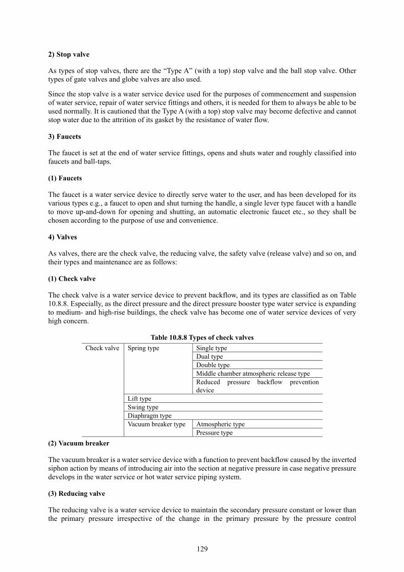
129
2) Stop valve
As types of stop valves, there are the “Type A” (with a top) stop valve and the ball stop valve. Other types of gate valves and globe valves are also used.
Since the stop valve is a water service device used for the purposes of commencement and suspension of water service, repair of water service fittings and others, it is needed for them to always be able to be used normally. It is cautioned that the Type A (with a top) stop valve may become defective and cannot stop water due to the attrition of its gasket by the resistance of water flow.
3) Faucets
The faucet is set at the end of water service fittings, opens and shuts water and roughly classified into faucets and ball-taps.
(1) Faucets
The faucet is a water service device to directly serve water to the user, and has been developed for its various types e.g., a faucet to open and shut turning the handle, a single lever type faucet with a handle to move up-and-down for opening and shutting, an automatic electronic faucet etc., so they shall be chosen according to the purpose of use and convenience.
4) Valves
As valves, there are the check valve, the reducing valve, the safety valve (release valve) and so on, and their types and maintenance are as follows:
(1) Check valve
The check valve is a water service device to prevent backflow, and its types are classified as on Table 10.8.8. Especially, as the direct pressure and the direct pressure booster type water service is expanding to medium- and high-rise buildings, the check valve has become one of water service devices of very high concern.
Table 10.8.8 Types of check valves
Check valve Spring type Single type Dual type Double type Middle chamber atmospheric release type Reduced pressure backflow prevention device
Lift type Swing type Diaphragm type Vacuum breaker type Atmospheric type
Pressure type
(2) Vacuum breaker
The vacuum breaker is a water service device with a function to prevent backflow caused by the inverted siphon action by means of introducing air into the section at negative pressure in case negative pressure develops in the water service or hot water service piping system.
(3) Reducing valve
The reducing valve is a water service device to maintain the secondary pressure constant or lower than the primary pressure irrespective of the change in the primary pressure by the pressure control
130
mechanism of the control spring, diaphragm, valve body etc.
The location of setting the reducing valve shall be where its inspection and replacement after installation are easy, and, at the time of setting, it shall be confirmed if proper reduction of pressure has been done. After its installation, regular inspection needs to be conducted so that normal operation is assured.
(4) Safety valve (release valve)
The safety valve is a water service device to release excessive pressure by automatically opening the valve body if the primary pressure becomes higher than the prescribed value, and the valve body closes as the pressure falls below the prescribed value.
For installation of the safety valve, its inspection and replacement shall be taken into account, and it is needed to be used in combination with a reducing valve.
Moreover, it is needed to confirm that regular inspection is conducted after its installation so that it is working normally.
2. Water service devices of water saving type
Water service devices of water saving type are classified into one, with which water saving has been designed, and the other one, with which water is naturally saved. Expansion of the use of water service devices of water saving type shall be pushed forward not only where the need for water saving is high, but in other areas so as to utilize limited water resources effectively and rationally. The classification and outline of water service devices of water saving type are presented on Table 10.8.18.

131
Table 10.8.18 Classification and outline of water service devices of water saving type
Classification Device Structure
Water saving type
Water saving type low-tank toilet
Water per flushing is saved to 6 to 8 liters compared with 12 to 20 liters of the conventional type.
Water saving type flush valve for large size toilet bowl
A valve, which gives only 12 liters per action even if the handle is held down.
Wat
er s
avin
g ca
n be
ach
ieve
d
Limited discharge
Constant volume valve A valve, which allows discharge of fixed volume of water irrespective of water pressure
Foaming faucet A faucet, which spouts foaming water mixed with air
Auto-shut structure
Hygienic hand wash valve With the handle lifted, water spouts and automatically stop when the hand is put off the handle.
Auto-closing faucet When the hand is off the handle, water spouts and automatically stops by action of a spring
Electronic faucet If an infrared light beam etc. is blocked off, spout and stop of water are automatically controlled as electronic device works.
Faucets in public baths A faucet, which automatically stops when the hand is off the handle
Constant volume faucet By setting the handle at a scale as required, water stops after spouting the indicated volume and stops automatically.
Control method
Unit for the urinal flushing -Sensor-control method -Fixed time control method
Unit for toilet bowl flushing Composed of automatic flush valve and a signal device, volume of water is controlled by time sensed of human body by photoelectric sensor etc.
Solenoid valve for flushing urinal
A valve, which electrically opens and shuts by means of attraction action of electromagnet or a signal of automatic control unit
Full-auto washing machine, and automatic washing machine
Automatically sensing the quantity of the laundry, quantity of water to be fed to the washing machine is controlled.
Automatic dish washing machine
Selecting a program depending on degree of stain and other conditions, used water is saved.
Others Toilet bowl flushing unit Using a sensor etc., toilet bowl is flushed according to degree of stain.
Water saving faucet top (faucet parts)
A top, which limits discharge of water at about half the ordinary discharge, compared with the ordinary top, at the aperture of the handle used normally.
10.9. Water Meter 10.9.1. General
Since the water meter (hereafter “the meter”) is the base of computation of the water rate, the one, which has passed the examination of scales prescribed in the Measurement Law (1992 Law No. 51), and is within the validity date, shall always be used. For maintenance of the meter, efforts need to be made to maintain its accuracy of measurement, and keep it in such a condition that its reading, replacement etc. can easily be performed at any time.
Although the current technical standards for the meter are prescribed in “Specific scales examination rules based on the Measurement Law” (1993 Ministry of Economy and Industry Ordinance No. 70) (Commonly called “Exam Rules”), the ministry in charge of the rules made the technical standards of the (water) meter the JIS standards, and decided to cite them for the examination so as to speedily respond the progress of technologies, and promote international unification.
132
10.9.2. Types and Characteristics of Meters
As meters have different structures depending on type, and indigenous characteristics, it is needed to fully understand their property and select, set and maintain them in accordance with the situation of their use. Classification and characteristics by their type are as shown on Table 10.9.1.
10.9.3. Improvement of Environment for Meter Installation
As the environment of the location of installation of the meter changes at times due to an expansion or reform of the house etc., the situation shall carefully be observed at the occasion of meter reading etc., and the requirements for the location of the meter shall be explained to the consumers at every given occasion so that efforts are made to secure the proper location. Whenever a meter installed under improper environment is found, the owner of the meter shall be instructed to move it to an appropriate location.
10.9.4. Maintenance of the meter
1. Inspection related to questionable meter reading
Of disorders of the meter, a stall of the indicator, broken glass, leakage from the gasket, blurred panel etc. can easily be detected at the time of meter reading, but it is difficult to find lagged movement, random movement, idle run, overrun etc. These disorders can be found at the time of regular meter reading, when the reading is questioned by the request etc. of the consumer by means of a survey and inspection of the meter at site on the situation of its use including the existence of a disorder.
Disorder, failure and their causes of the meter in use are presented on Table 10.9.3.

133
Table 10.9.1 Classification by the principle of measurement and characteristics
Type Principle Characteristics (1)Tangential flow wheel type meter
Turning the wheel by water flow from tangential direction, passing volume is integrated and shown on the indicator.
-Mainly used for meters of diameter of smaller than 40 mm. -Meters of smaller diameter than 25 mm are used for ordinary homes. -As to the indicator unit, the dry type is mainly in use because of its ease of reading and anti-freeze property.
(2)Axial flow wheel type meter
Turning the helical wheel by passing water parallel with it, passing volume is integrated and shown on the indicator. This type of meter is named Woltmann meter or turbine meter, and there are the vertical type, in which the wheel is set plumb, and the horizontal type, in which the wheel is set horizontally.
a. Vertical type Woltmann -Although pressure loss is relatively large, sensitivity is good, so suitable to measure a wide range of volume from small flow to large flow. - There are ones of disunited type, and the united type jointly developed by the Japan Water Meter Industry Association and the six cities Note) made of cast copper alloy. b. Horizontal type Woltmann -Although its property for small flow is a little inferior, suitable for measurement of large flow. - As being small and light compared with the vertical one, its mounting and dismantling are easy.
(3)Venturi pipe type bypass flow meter
Applying the Bernoulli’s principle, utilizing the differential pressure occurring when water passes a Venturi pipe, water volume passing the Venturi pipe is measured by a small meter set in the bypass pipe.
-Owing to its structural feature, excellent in durability, and suitable for the use for continued relatively large flow. But as sensitivity is low for small flow compared with the wheel type, inapplicable where water pressure is law. - Although, in general, has been used for water flow control in a factory etc., the electromagnetic type flow meter is the mainstream in recent years.
(4)Meter with bypass pipe
Combining a large diameter meter (parent meter) and a small one in parallel, the small meter (baby meter) is used when flow is small by closing the switching valve; both meters are used when flow is large. The switching valve works automatically.
-Can measure a wide range of water flow from minute flow to large flow. - In general, used in hospitals, schools etc. at which change in water consumption is large.
(5)Electromagnetic meter
Applying the Faraday’s law as the principle of measurement, there are one with external power source, and the other one with an internal source.
-As having no moving parts and causing no head losses, such an accident as intake of impurities of sand etc. or accident due to continuous use of large flow does not occur, or there is also no restriction about the position of mounting.
(6)Ultrasonic wave type meter
Using the difference in travelling time of ultrasonic waves between two points when water flow passes them, flow is computed, integrated and indicated.
-As having no moving parts and causing no head losses, such an accident as intake of impurities of sand etc. or accident due to continuous use of large flow does not occur, or there is also no restriction about the position of mounting.
(7)Disk type meter (8)Rotary piston type meter
Measurement is made as water is measured by a measuring cup.
-Both sensitivity and accuracy are excellent, and especially, minute water volume can precisely be measured. - High precision is required for structural parts of measuring unit, so easily tends to fail by intrusion of such solid matter as scale. Thus, as its maintenance is difficult, and it is expensive, it is used for testing etc.
Note) Metropolitan Tokyo, Yokohama City, Nagoya City, Osaka City, Kyoto City, Kobe City

134
Table 10.9.3 Disorder, failure and their causes of the meter
Disorder Cause 1.Lagged movement (Integrated value is smaller the actual one)
1) Contamination of foreign matters
As sand or silt enters inside, the friction in the rotating part is large.
2)Excessively large flow Friction in the rotating part is large due to damage or attrition of the bearing, pivot, gear etc.
3) Excessively small flow The current flow is smaller than the lower limit of the proper flow.
4)Freezing Breakage of the gear and the gear of the pinion due to freeze.
5)Water hammer Breakage of the indicator units by water hammer
2,Random movement (Disorderly needle movement)
1)Contamination with foreign matters, 2)excessively large flow, 3)Freeze, 4) water hammer
Smooth movement of the meter is lost because of breakage of gears etc. caused by these events.
3.Stoll of movement (Stuck mechanism)
The rotating parts get stuck due to the same causes as 1. and 2 above
4.Reverse rotation 1)Meter installed in reverse direction
The entering direction of water is backward.
2) Excessively large flow Breakage of the gear, or its disengagement 5.Idle run 1) Excessively large flow
2)Freezing 3) Water hammer
The gear runs idle because of their loose engagement and attrition by friction due to these events.
6.Overrun 1)Escape of gasket By concentrated water stream, indicated value becomes more than the actual one.
2)Clogged strainer Concentrated stream occurs by foreign matters.
3)Leakage Due to leakage downstream of the meter 7.Broken glass 1)Freezing
2) Water hammer 3)External force
Leakage occurs as the glass gets broken by these events.
8.Leakage from gasket 1)Slackness and cut of gasket Occurrence of leakage 2)Deterioration of gasket Impaired sealing function due to aging
9.Blurred display 1)Contamination of foreign objects
Stain by rust, scale etc.
2)Attachment of waterdrops Blur due to difference in temperature
2. Replacement and repair of the meter
As for replacement of the meter, there are two occasions, namely, its replacements at the end of eight years of validity for its official examination, and when it fails for some reasons. The dismantled meters can be used again after repair that is prescribed in the Measurement Law.
3. Management of the meter
Since the meter is a specific measurement stipulated in the Measurement Law, and a precision measurement instrument, adequate care needs to be exercised for its handling. What’s more, as the quantity of handling and cost of meters for a water utility are large, their detailed management is required.
135
10.9.5. Remote Meter (Annotation is omitted.)
10.9.6. Meter Reading System (Annotation is omitted.)
10.9.7. Incorporation of the Water Meter into JIS and Revision of the Examination Rule
(Annotation is omitted.)
[Reference] Japanese Industrial Standards (JIS) B 8570-1: 2013
Meters for cold water and hot water-Part 1: General specifications
Preface
This standard is a Japanese Industrial Standard (JIS) prepared with revised technical details in consideration of the actual status of the use of water meters for cold water and hot water in Japan based on ISO 4064-1 and ISO 4064-2 which was published as the Third Edition in 2005.
Besides, the underlined parts in this standard are the items revised from the identical international standards.
A table of the revised portions is presented in Attachment JF together with their annotations.
1. Scope of application
This standard stipulates on the water meter, which can stand the maximum pressure of 1 MPa (0.6 MPa for meters of nominal diameter of more than 500) and measures the volume of cold water flowing in the pipe at temperature of less than 30 degrees centigrade, and the hot water meter (hereafter, in this standard, simply called “meter” for the standard commonly applied to both meters), which measures the volume of clean hot water flowing in the pipe of temperature at less than 180 degrees centigrade
Furthermore, this standard also applies to the meter with electric or electronic principle, the mechanical meter with an electronic device, and the electronic attachments.
Annotation: International standards corresponding to this standard and the symbols to indicate the magnitude of correspondence are shown below:
ISO 4064-1: 2005,Measurement of water flow in fully charged closed conduits-Meters for cold potable water and hot water-Part 1: Specifications
ISO 4064-3: 2005,Measurement of water flow in fully charged closed conduits-Meters for cold potable water and hot water-Part 3: Test methods and equipment(Overall evaluation:MOD)
Additionally, “MOD”, which indicates the magnitude of correspondence, denotes “modified” based on ISO/IEC Guide 21-1.