Embed Size (px)
Citation preview

AAiT Water Supply & Urban Drainage By Zerihun Alemayehu
Water Transmission Lines • Transmission lines are long pipes with no
withdrawals
▫ Gravity main
▫ Pumping main

AAiT Water Supply & Urban Drainage By Zerihun Alemayehu
Gravity main
ho + Zo – ZL = H (Head loss + residual pressure)

AAiT Water Supply & Urban Drainage By Zerihun Alemayehu
Pumping main
ho = H + ZL – Zo + Head loss

AAiT Water Supply & Urban Drainage By Zerihun Alemayehu
Layout of distribution systems • Pipe networks : ▫ Primary or arterial mains from the pumping stations and from storage facilities
to the various districts of the city. valved at intervals of not ≤ 1.5 km
▫ Secondary lines or Sub-mains run from one primary main to another located at spacings of 2-4 blocks
▫ Small distribution mains or branches Supply water to every consumer and to the fire
hydrants

AAiT Water Supply & Urban Drainage By Zerihun Alemayehu
Layout of distribution systems • layout of distribution pipes generally follows the
road pattern • four types of pipe network layouts – ▫ dead end system or branch system, ▫ gridiron system, ▫ ring system, and ▫ radial system.
AAiT
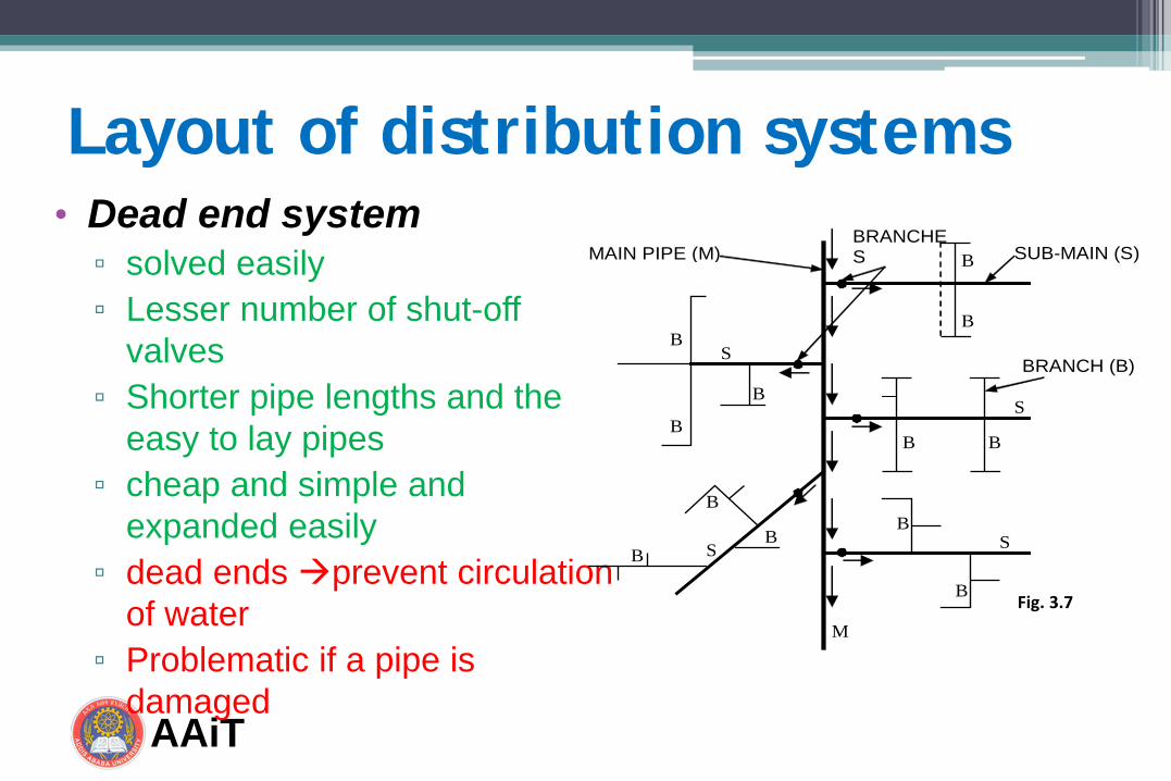
Layout of distribution systems • Dead end system ▫ solved easily ▫ Lesser number of shut-off
valves ▫ Shorter pipe lengths and the
easy to lay pipes ▫ cheap and simple and
expanded easily ▫ dead ends prevent circulation
of water ▫ Problematic if a pipe is
damaged
MAIN PIPE (M)
B
SUB-MAIN (S)
BRANCH (B) S
B
B
B
B
S B
M
B
S B
B
B
S
B
B BRANCHES
Fig. 3.7

AAiT Water Supply & Urban Drainage By Zerihun Alemayehu
Layout of distribution systems • Gridiron systems ▫ Discharge, friction loss and pipe
size is less ▫ Not problematic if a pipe is
damaged ▫ No dead ends allows
circulation of water ▫ Good for fire fighting ▫ more pipelines and shut-off
valves ▫ high cost of construction ▫ design is difficult and expensive
AAiT
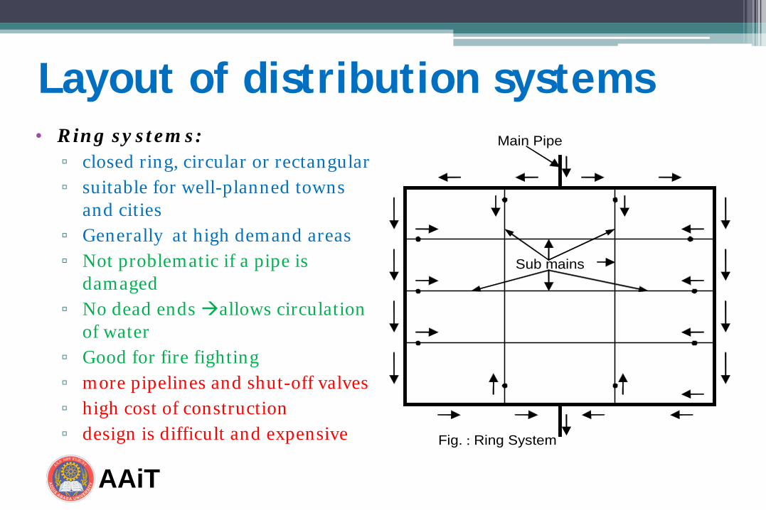
Layout of distribution systems • Ring systems:
▫ closed ring, circular or rectangular ▫ suitable for well-planned towns
and cities ▫ Generally at high demand areas ▫ Not problematic if a pipe is
damaged ▫ No dead ends allows circulation
of water ▫ Good for fire fighting ▫ more pipelines and shut-off valves ▫ high cost of construction ▫ design is difficult and expensive
Sub mains
Main Pipe
Fig. : Ring System
AAiT
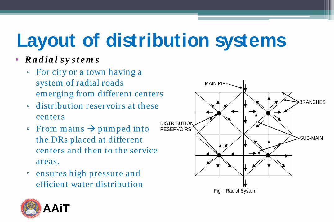
Layout of distribution systems • Radial systems ▫ For city or a town having a
system of radial roads emerging from different centers
▫ distribution reservoirs at these centers
▫ From mains pumped into the DRs placed at different centers and then to the service areas.
▫ ensures high pressure and efficient water distribution
MAIN PIPE
BRANCHES
DISTRIBUTION RESERVOIRS
SUB-MAIN
Fig. : Radial System

AAiT Water Supply & Urban Drainage By Zerihun Alemayehu
Design of distribution systems • Design flow: Max (Peak hour demand or maximum day
demand + Fire demand) • Minimum main sizes: generally:150mm (6 in); high value
districts: 200mm (8 in); major streets: 305mm (12 in); domestic flows only: 100mm (4 in); small communities: 50-75 mm
• Velocity: typical values – minimum = 0.6 - 1 m/s; maximum = 2.5 m/s
• Pressure: typical minimum value is 140 kPa (14 m) and maximum not to exceed 410 kPa (42 m). But mainly depends on pressure ratings of the pipes and appurtenances used and regulatory requirements

AAiT Water Supply & Urban Drainage By Zerihun Alemayehu
Pressure zones

AAiT Water Supply & Urban Drainage By Zerihun Alemayehu
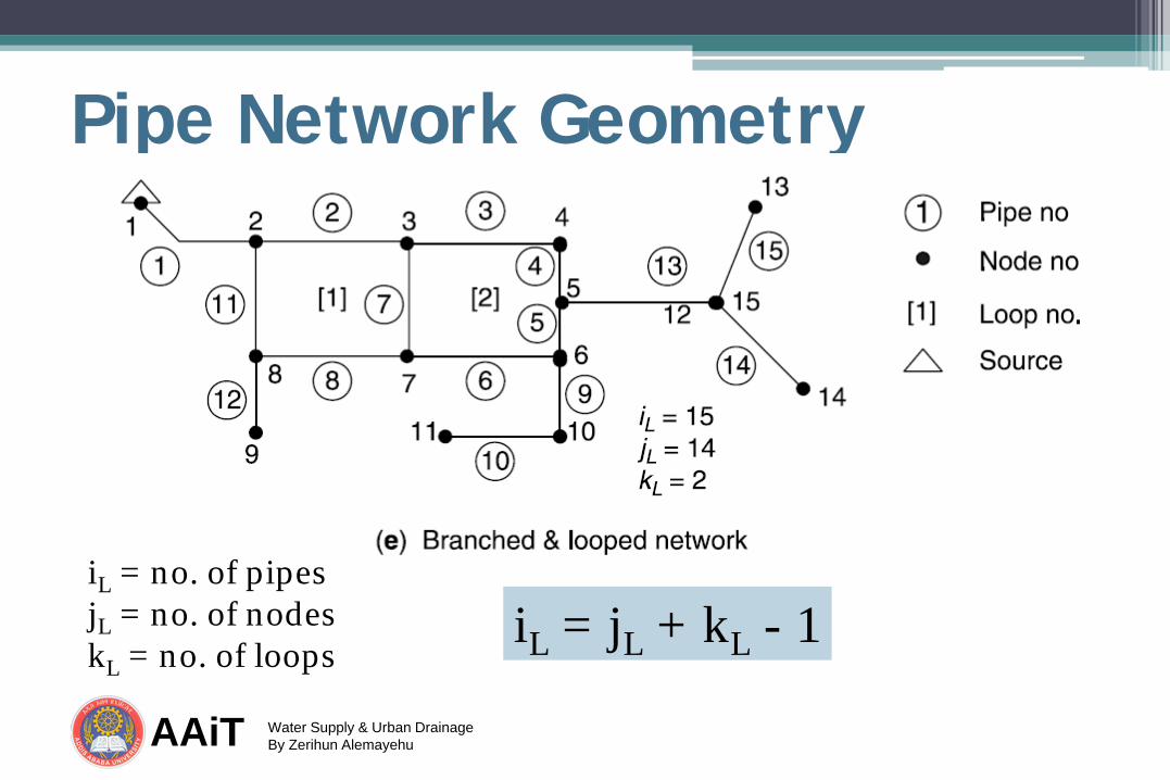
Pipe Network Geometry
iL = no. of pipes jL = no. of nodes kL = no. of loops
iL = jL + kL - 1

AAiT Water Supply & Urban Drainage By Zerihun Alemayehu
Pipe Network Geometry
iL = no. of pipes jL = no. of nodes kL = no. of loops
iL = jL + kL - 1
AAiT Water Supply & Urban Drainage By Zerihun Alemayehu
Pipe Network Geometry
iL = no. of pipes jL = no. of nodes kL = no. of loops
iL = jL + kL - 1

AAiT Water Supply & Urban Drainage By Zerihun Alemayehu
• Includes determination of the following:
Hydraulic analysis
Discharges
Head loss
Pressure head

AAiT Water Supply & Urban Drainage By Zerihun Alemayehu
Basic principles of pipe flow
𝑄 =𝜋4𝐷2𝑣

AAiT Water Supply & Urban Drainage By Zerihun Alemayehu
Friction Losses Equation Formula Remarks Manning’s
𝑉 =1𝑛𝑅2/3𝑆1/2
commonly used for open channel flow.
Chezy’s (Kutter’s)
𝑉 = 𝐶 𝑅𝑆 Widely used in sanitary sewer design and analysis
Hazen-Williams
𝑉 = 0.85𝐶𝑅0.63𝑆0.54 Commonly used in the design and analysis of pressure pipe systems
Darcy-Weisbach 𝑉 =
8𝑔𝑓𝑅𝑆
Can be used for pressured pipe systems and open channel flows.
AAiT Water Supply & Urban Drainage By Zerihun Alemayehu
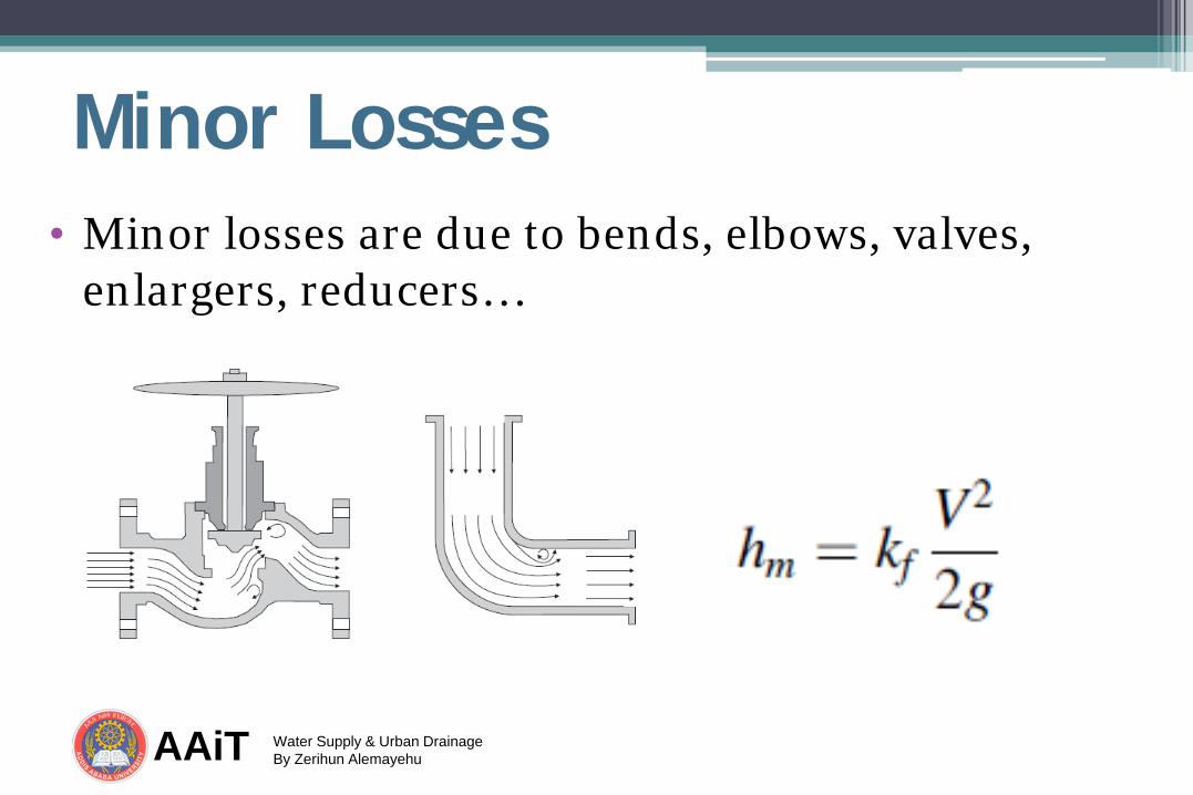
Minor Losses • Minor losses are due to bends, elbows, valves,
enlargers, reducers…

AAiT Water Supply & Urban Drainage By Zerihun Alemayehu
• Hydraulic analysis methods ▫ Hardy cross method ▫ Computer programs
• The Hazen-William equation is widely used to determine the head loss in a pipe.
54.0f63.2
LhCD278.0Q
=
Hydraulic Analysis of DS
AAiT Water Supply & Urban Drainage By Zerihun Alemayehu
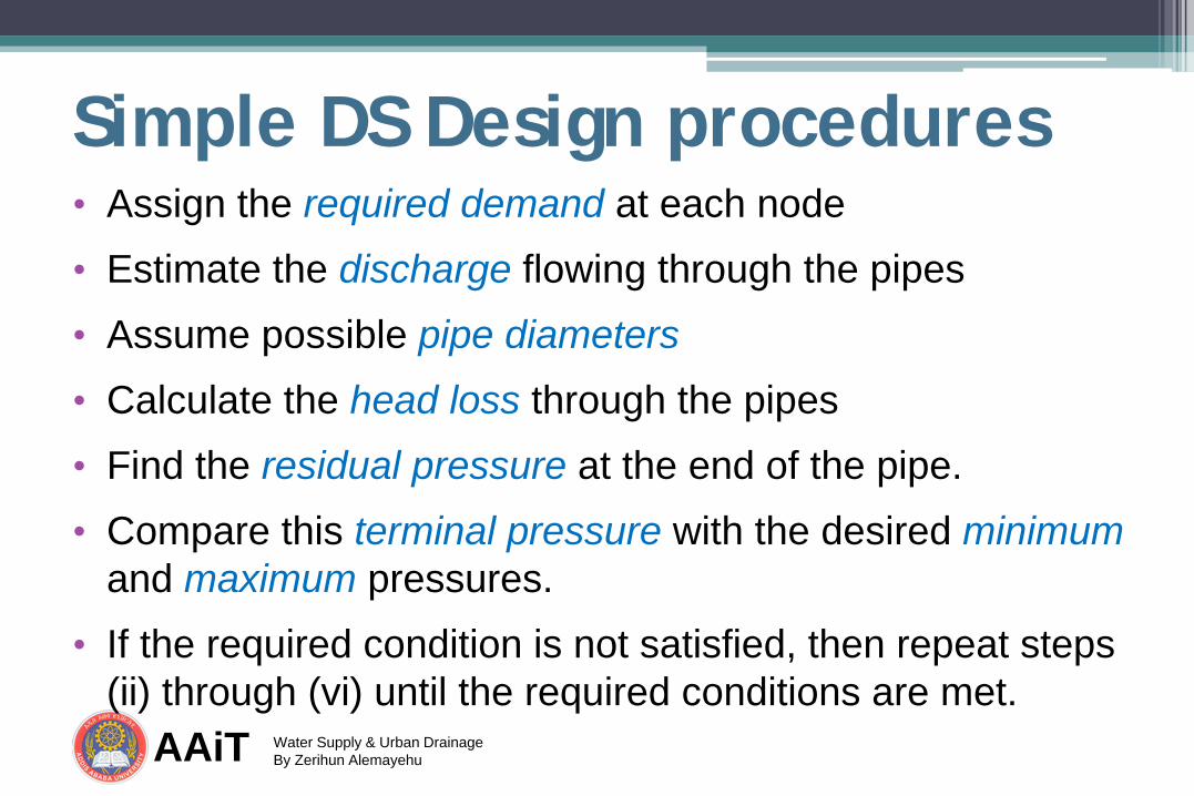
Simple DS Design procedures • Assign the required demand at each node • Estimate the discharge flowing through the pipes • Assume possible pipe diameters • Calculate the head loss through the pipes • Find the residual pressure at the end of the pipe. • Compare this terminal pressure with the desired minimum
and maximum pressures. • If the required condition is not satisfied, then repeat steps
(ii) through (vi) until the required conditions are met.
AAiT Water Supply & Urban Drainage By Zerihun Alemayehu
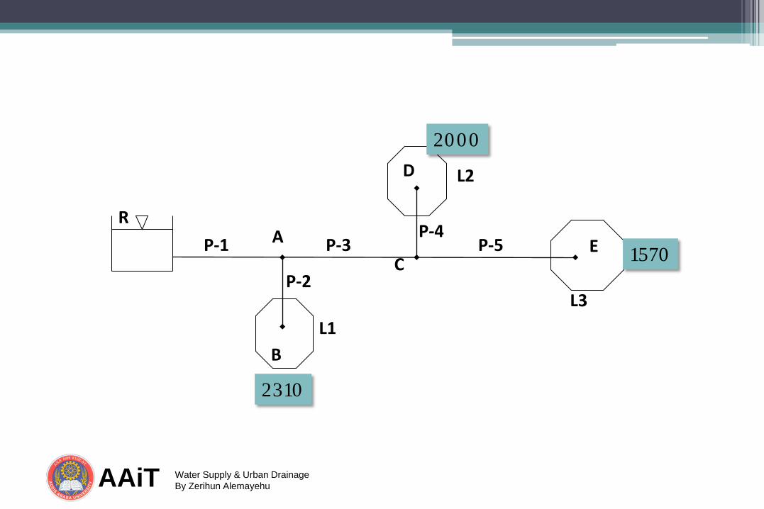
B
D
E P-1
P-2
P-3 P-4
P-5 R
L1
L2
L3
A C
2000
1570
2310

AAiT Water Supply & Urban Drainage By Zerihun Alemayehu
Complex pipe Networks • Hardy Cross Method can be used • Assign the required demand at each node • Assume the best distribution of flow that satisfies
continuity by careful examination of the network. ▫ The flow entering a node must be equal to the flow
leaving the same node
Design procedures...
AAiT Water Supply & Urban Drainage By Zerihun Alemayehu
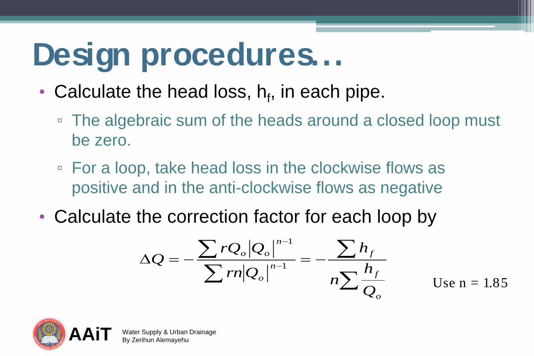
Design procedures... • Calculate the head loss, hf, in each pipe. ▫ The algebraic sum of the heads around a closed loop must
be zero.
▫ For a loop, take head loss in the clockwise flows as positive and in the anti-clockwise flows as negative
• Calculate the correction factor for each loop by
∑∑
∑∑ −=−=∆ −
−
o
f
fn
o
noo
Qh
n
h
Qrn
QrQQ 1
1
Use n = 1.85

AAiT Water Supply & Urban Drainage By Zerihun Alemayehu
Example
A
B
D
E C
R 150 m
200 mm
200 m
200 mm
250 m
75 mm
50 m
75 m
m
75 m
75 m
m
El. 1207 El. 1250
El. 1192
El. 1167
El. 1177
El. 1185
Q = 1 m3/min
Q = 0.75 m3/min
Q = 0.25 m3/min
Determine velocity and residual
Pressure at the demand centers.

AAiT Water Supply & Urban Drainage By Zerihun Alemayehu
Solution: Velocity Calculation
A
B
D
E C
R Q = 2 m3/min
150 mm
v = 1.9 m/s
Q = 1 m3/min
125 mm
v = 1.4 m/s
Q = 0.25 m3/min
75 mm
v = 0.9 m/s
Q = 0.75 m3/min
100 mm
v = 1.6 m/s
Q = 1 m3/min
100 mm
v = 2.1 m/s
El. 1250
Q = 1 m3/min
Q = 0.75 m3/min
Q = 0.25 m3/min
Velocity is calculated as 𝑉 = 𝑄
𝜋 𝑑2
4

AAiT Water Supply & Urban Drainage By Zerihun Alemayehu
Solution: Head loss calculation
A
B
D
E C
R Q = 2 m3/min
150 mm, 150 m
hl = 6.04 m
Q = 1 m3/min
125 mm, 200 m
hl = 5.43 m
Q = 0.25 m3/min
75 mm, 250 m
hl = 6.27 m
Q = 0.75 m3/min
100 mm, 50 m
hl = 2.36 m
Q = 1 m3/min
100 mm, 75 m
hl = 6.03 m
El. 1250
Head loss is calculated as
ℎ𝑙 = 10.68𝐿
𝐷4.866𝑄𝐶
1.85
AAiT Water Supply & Urban Drainage By Zerihun Alemayehu
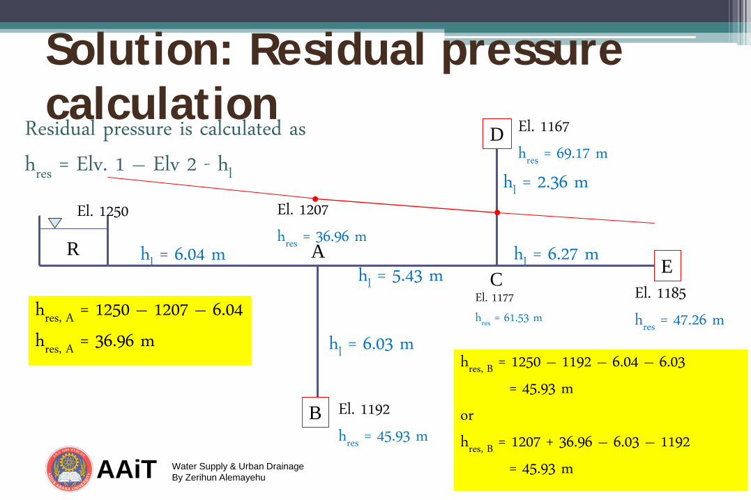
Solution: Residual pressure calculation
A
B
D
E C
R
El. 1207
hres = 36.96 m El. 1250
El. 1192
hres = 45.93 m
El. 1167
hres = 69.17 m
El. 1185
hres = 47.26 m
Residual pressure is calculated as
hres = Elv. 1 – Elv 2 - hl
hl = 6.04 m hl = 5.43 m
hl = 6.27 m
hl = 2.36 m
hl = 6.03 m
hres, A = 1250 – 1207 – 6.04
hres, A = 36.96 m
El. 1177
hres = 61.53 m
hres, B = 1250 – 1192 – 6.04 – 6.03
= 45.93 m
or
hres, B = 1207 + 36.96 – 6.03 – 1192
= 45.93 m

AAiT Water Supply & Urban Drainage By Zerihun Alemayehu
Reading assignment • From your Hydraulics II course
▫ Pipe network analysis
▫ Hardy-cross method
▫ Newton Raphson method
▫ Linear Theory method
▫ EPANET

AAiT Water Supply & Urban Drainage By Zerihun Alemayehu
Example
Determine the discharge in each of the pipes using Hard-Cross Method

AAiT Water Supply & Urban Drainage By Zerihun Alemayehu
First Trial

AAiT Water Supply & Urban Drainage By Zerihun Alemayehu
Second Trial

AAiT Water Supply & Urban Drainage By Zerihun Alemayehu
Third Trial
AAiT Water Supply & Urban Drainage By Zerihun Alemayehu
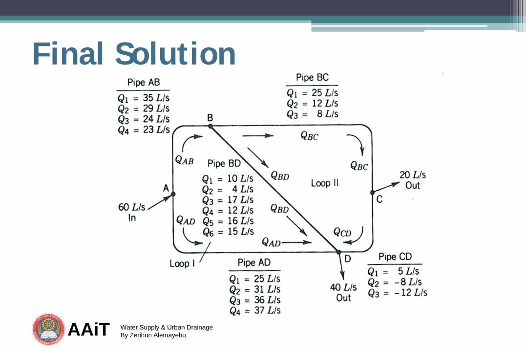
Final Solution

AAiT Water Supply & Urban Drainage By Zerihun Alemayehu
Water Distribution Modeling

AAiT Water Supply & Urban Drainage By Zerihun Alemayehu
WDS Simulation • Simulation: the process of imitating the
behavior of one system through the functions of another.
• refers to the process of using a mathematical representation of the real system, called a model.
AAiT Water Supply & Urban Drainage By Zerihun Alemayehu
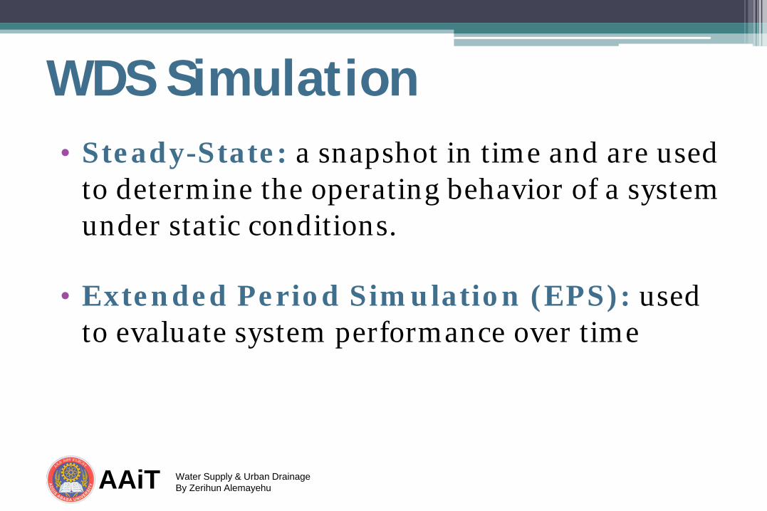
WDS Simulation • Steady-State: a snapshot in time and are used
to determine the operating behavior of a system under static conditions.
• Extended Period Simulation (EPS): used to evaluate system performance over time

AAiT Water Supply & Urban Drainage By Zerihun Alemayehu
Application of WDMs • Long-range master planning, both new
development and rehabilitation • Fire protection studies • Water quality investigations • Energy management • System design • Daily operational uses including operator
training, emergency response, and • troubleshooting

AAiT Water Supply & Urban Drainage By Zerihun Alemayehu
Model Representation Nodes
Links

AAiT Water Supply & Urban Drainage By Zerihun Alemayehu
Network Elements
AAiT Water Supply & Urban Drainage By Zerihun Alemayehu
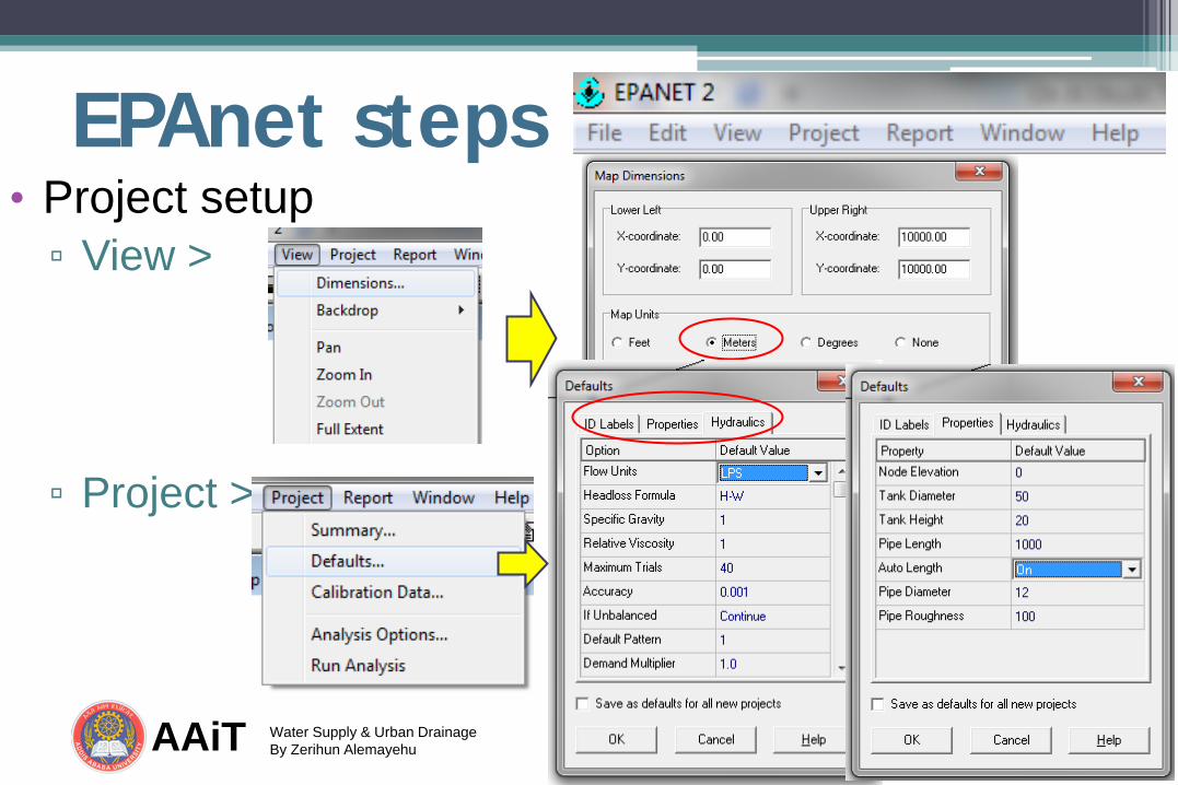
EPAnet steps • Project setup ▫ View >
▫ Project >

AAiT Water Supply & Urban Drainage By Zerihun Alemayehu
EPAnet steps … • Model building ▫ First construct nodes (Reservoirs, tanks,
junctions) ▫ Then connect links (pumps, pipes, valves)
Add junction Add reservoir
Add tank Add pipe Add pump
Add valve
Add lable
AAiT Water Supply & Urban Drainage By Zerihun Alemayehu
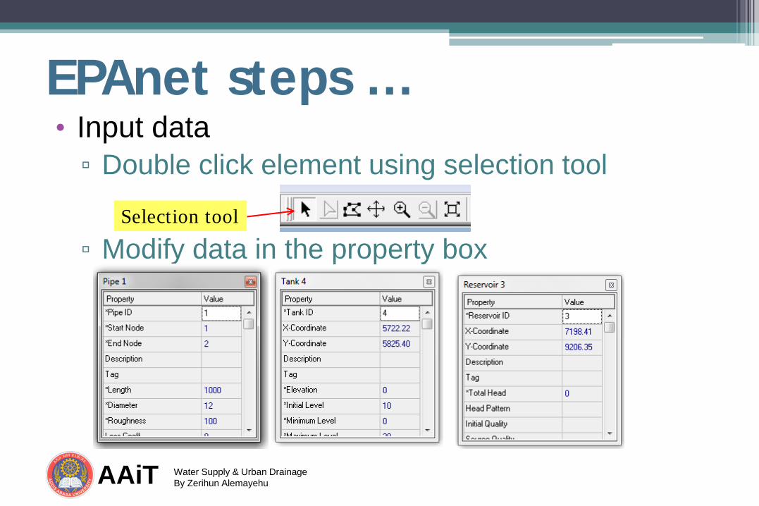
EPAnet steps … • Input data ▫ Double click element using selection tool ▫ Modify data in the property box
Selection tool

AAiT Water Supply & Urban Drainage By Zerihun Alemayehu
EPAnet steps … • Run the model
• View result
Run tool
View graphs View table