Embed Size (px)
Citation preview
TOWN OF DOUGLAS
59 CHARLES STREET
P.O. BOX 624
DOUGLAS, MASSACHUSETTS 01516
(508) 476-2400
WATER-WASTE WATER
SPECIFICATIONS
WATER MAINS AND APPURTENANCES
PART 1 GENERAL
1.01 WORK INCLUDED
A. Furnishing pipe for water main extensions.
B. Furnishing miscellaneous appurtenances.
C. Installation.
D. Testing.
1.02 REFERENCE STANDARDS
A. ANSI A21.4/AWWA C104 - Cement Mortar Lining for Ductile Iron and Gray Iron Pipe and Fittings for Water.
B. ANSI A21.10/AWWA C110 - Gray Iron and Ductile . Iron Fittings, 3" through 48", for Water and Other Liquids.
C. ANSI A21.53/AWWA C153 - Compact Ductile Iron Fittings " through 42" for water and other liquids.
D. ANSI A21.11/AWWA C111 . - Rubber Gasket Joints for Ductile Iron and Gray Iron Pressure PiPe and Fittings.
E. ANSI A21.51/AWWA C151 - Ductile Iron Pipe.
F. ANSI B.16 - Cast Iron Pipe Flanges and Flanged Fittings, Class 25, 125, 250 and 800.
G. AWWA C504 - Butterfly Valves, 3" through 24" NPS for water and other liquids.
H. AWWA C509 - Resilient Seat Gate Valves.
I. AWWA C600 - Installation of Cast Iron Water Mains.
J. AWWA C601 - Disinfecting Water Main.

Water Main and Appurtenances
Page 2
PART 2 WATER WORKS MATERIALS
2.01 GENERAL
A. All water works materials included in this section shall conform to the requirements of the standard specifications referenced herein.
B. Pipe size shall be as shown in the table below.
C. All pipe materials and methods of jointing shall be as specified in this Section.
2.02 PIPE AND FITTINGS
A. Ductile Iron Pipe: Pipe shall conform to ANSI A21.51/AWWA C151, and shall have push-on joints except that pipe installed in vaults shall have flanged ends conforming to ANSI B16.1. Push-on joints and rubber gaskets shall be in accordance with ANSI.11/AWWA C111. Cement mortar lining shall be double cement-lined, conforming to ANSI A21.4/AWWA C104. The minimum thickness shall be 1/8-inch for 6-inch through 12-inch pipe and a minimum,of 3/16-inch for 14-inch through 24-inch pipe. It shall be free of any crazing or cracks in the cement lining and shall have a bituminous seal coating, uniform in thickness properly applied, both inside and outside of all pipe.
The pipe shall be Class 52 with the following thickness:
Size Thickness
6-inch 0.31
10-inch 0.35
12-inch 0.37
16-inch 0.40
B. Testing Certification for Ductile Iron Pipe
1. The pipe manufacturer shall supply the Water Department with certificates of compliance with these specifications and certification that each piece of ductile iron pipe has been tested at the foundry with the Ball Impression Test, Ring Bending or other approved test for ductility.
C. Pipe Fittings:
1. Fittings shall be cast iron, 250 psi pressure rating, or ductile iron, 350 psi pressure rating, conforming to ANSI A21.10/AWWA C110 with mechanical joints. Compact ductile iron fittings conforming to ANSI A21.53/AWWA C153 will be acceptable. Joints and gaskets shall conform to ANSI 21.11/AWWA C111. Joints shall be furnished with standard ductile iron accessories or retainer glands if specified.

Water Main and Appurtenances
Page
Fittings shall be double cement-lined as specified above and seal- coated inside and out with an asphalt coating uniform in thickness, properly applied in accordance with ANSI A21.4/AWWA C104. Tees for hydrant branches and for stubs for future use shall have mechanical joints on the run with a plain end having an integral rotating gland on the branch. The gland will anchor mechanical joint pipe or valve ends to the plain end of the tee.
2.03 VALVES
A. Gate Valves - Resilient Seat
1. Gate valves may be resilient seated manufactured to meet or exceed the requirements to AWWA C-509 with latest revision. Valves shall have an unobstructed water way when fully opened equal in diameter to at least 1/4" greater than the nominal valve size.
2. All internal surfaces shall be coated with epoxy to a minimum thickness of 4 mils. Said coating shall be non-toxic, impart no taste to water and shall conform to AWWA C-550 of latest revision.
3. Valves shall be provided with two 0-ring stem seals. One antifriction washer shall be located below and one antifriction washer above the thrust collar. The sealing mechanism shall provide zero leakage at the water working pressure when installed with the line flow in either direction, and shall consist of a cast iron or ductile iron gate having a vulcanized synthetic rubber coating with no rubber metal seams or edges in the water way when in the fully closed position.
4. All valves shall be seat tested at the rated working pressure in accordance with Section 6 of AWWA C-509. All valves shall be rated at 200 psi working pressure and 400 psi test pressure.
5.. Valves shall open left.
6. All resilient seated gate valves shall be M & H, the Town Standard.
B. Butterfly Valves
1. All valves 12-inch and over shall be butterfly valves. All butterfly valves shall be of the rubber-seated tight-closing type and shall meet or exceed AWWA Specification C-504-70, with latest revisions. Valves shall be designed for underground service.
' 2. Valves shall have mechanical joint ends. Standard M.J. accessories are also to be provided.
3. Valves shall open left and be equipped with a 2-inch AWWA operating nut.
Water Main and Appurtenances
Page 4
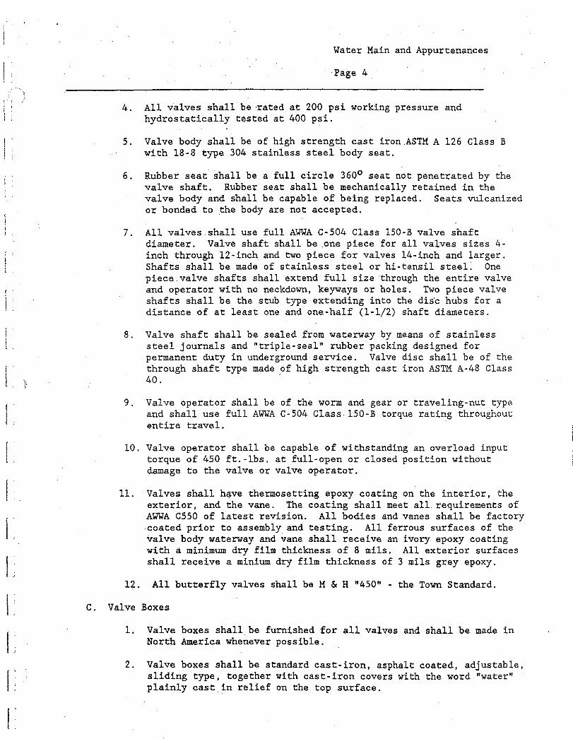
4. All valves shall berated at 200 psi working pressure and hydrostatically tested at 400 psi.
5. Valve body shall be of high strength cast iron ASTM A 126 Class B with 18-8 type 304 stainless steel body seat.
6. Rubber seat shall be a full circle 360° seat not penetrated by the valve shaft. Rubber seat shall be mechanically retained in the valve body and shall be capable of being replaced. Seats vulcanized or bonded to the body are not accepted.
7. All valves shall use full AWWA C-504 Class 150-B valve shaft diameter. Valve shaft shall be one piece for all valves sizes fl-inch through 12-inch and two piece for valves 14-inch and larger. Shafts shall be made of stainless steel or hi-tensil steel. One piece valve shafts shall extend full size through the entire valve and operator with no neckdown, keyways or holes. Two piece valve shafts shall be the stub type extending into the dis'c hubs for a distance of at least one and one-half (1-1/2) shaft diameters.
8. Valve shaft shall be sealed from waterway by means of stainless steel journals and "triple-seal" rubber packing designed for permanent duty in underground service. Valve disc shall be of the through shaft type made of high strength cast iron ASTM A-48 Class 40.
9. Valve operator shall be of the worm and gear or traveling-nut type and shall use full AWWA C-504 Class 150-B torque rating throughout entire travel.
10. Valve operator shall be capable of withstanding an overload input torque of 450 ft.-lbs. at full-open or closed position without damage to the valve or valve operator.
11. Valves shall have thermosetting epoxy coating on the interior, the exterior, and the vane. The coating shall meet all requirements of AWWA C550 of latest revision. All bodies and vanes shall be factory coated prior to assembly and testing. All ferrous surfaces of the valve body waterway and vane shall receive an ivory epoxy coating with a minimum dry film thickness of 8 mils. All exterior surfaces shall receive a minium dry film thickness of 3 mils grey epoxy.
12. All butterfly valves shall be M & H "450" - the Town Standard.
C. Valve Boxes
1. Valve boxes shall be furnished for all valves and shall be made in North America whenever possible.
2. Valve boxes shall be standard cast-iron, asphalt coated, adjustable, sliding type, together with cast-iron covers with the word "water" plainly cast in relief on the top surface.

Water Main and Appurtenances
Page 5
3. The bottom section shall have a minimum I.D. of 5-1/4-inches. the top section shall have a minimum diameter of 6-1/8-inches. There shall be a minimum 6-inch overlap between sections.
4. The bottom section shall be 48-inches in length for all butterfly valves and 36 inches in length for all gate valves. The top section shall be at least 26 inches in length and have a plain bottom. No three-piece combinations shall be acceptable.
5. Valve boxes shall be completely and thoroughly coated with bitumastic paint.
2.04 HYDRANTS
A. Hydrants shall conform to the requirements of AWWA C-502, and be designed for 150 psi working pressure tested to 300 psi hydrostatic. Hydrants shall have 6-inch mechanical joint shoe, 5-1/4-inch valve opening, and 5'-6" or 6 foot bury, open left with two 2-1/2-inch hose nozzles and one 4-1/2-inch pumper connection, National Standard Threads, operating nut and nozzle cap with non-kink safety chains.
B. Hydrants shall be the compression type, closing with the pressure. They shall be traffic model with safety flange and stem couplings. All hydrants shall be M&H Dresser 929 traffic model.
C. Hydrants shall have square stem and seat ring shall be bronze to bronze. All internal parts shall be removable through the bonnet. Seals shall of the 0-ring type and bonnet shall be provided with permanent leak-free lubrication. Hydrants shall employ a teflon thrust bearing to reduce operating torque and it shall not require lubrication. Hydrants shall have an ivory epoxy coating on the interior shoe and lower valve plate. Minimum dry film thickness of .3 mils.
D. Hydrants shall be able to be rotated 360 degrees. They shall have a positive closing, self-cleaning drain valve and drainage area shall be completely bronze or brass lined.
E. Hydrants shall be painted to match the town's standard color of red for the hydrant barrel and aluminum for the bonnet. Paint to be used shall be an epoxy paint approved by the Water Department.
2.05 MISCELLANEOUS
A. Flexible or transition couplings to be used in connecting two plain ends of ductile iron, pipe shall be of steel or ductile iron manufacturer with bolts and nuts complying with AWWA C-111. All flexible or transition couplings shall be Dresser or Rockwell.
Water Main and Appurtenances
Page 6
PART 3 EXECUTION
3.01 GENERAL
A. Pipe and accessories shall be handled and stored in such a manner as to insure that pipe is installed in sound, undamaged condition. Particular care shall be taken not to injure the pipe coating or lining.
B. AC, Ductile iron pipe and fittings and the cement linings are com-paratively brittle. Every care shall be taken in handling and laying pipe and fittings to avoid damaging the pipe or lining, scratching or marring machined surfaces, and abrasion of the pipe coating or lining.
C. Any pipe showing a distinct crack with no evidence of incipient fracture beyond the limits of the visible crack, if approved, may have the cracked portion cut off by, and at the expense of, the Contractor before the pipe is laid so that the pipe used is perfectly sound. The cut shall be made in the sound .barrel at a point at least 12 inches from the visible limits of the crack.
D. The contractor shall neatly cut off all existing house services prior to removal on all existing water mains being replaced to the satisfaction of the Water Superintendent.
E The contractor shall also neatly cut off all existing water mains at roadway intersections where existing valves and tees are scheduled to be replaced prior to the installation of the new water mains. All existing valves that are removed are to remain the property of the Water Department. The Contractor shall take care that all valves removed are not damaged during removal or damaged during temporary storage on the work site, All existing valves removed shall be returned to the Water Department yard the day of removal. They shall be carefully loaded and unloaded to prevent any valve damage under proper supervision. No dumping of valves from a loaded truck or piece of construction equipment shall be permitted.
F. If authorized, cutting of the pipe shall be done so that the cut is square and clean, without causing damage to the pipe lining. Unless otherwise authorized by the Water Superintendent, all pipe cutting shall be done by means of an approved type of power cutter. The use of hammer and chisel, or any other method which results in rough edges, chips and damaged pipe, is prohibited. All cut edges shall be field beveled by use of a power grinder when necessary before installation.
G. Each pipe section shall be placed into position in the trench in such manner and by such means required to cause no damage to the pipe, person or to property.
Water Main and Appurtenances
Page 7
H. The Contractor shall furnish good sound safe slings, straps and/or other approved devices to provide satisfactory support of the pipe when it is lifted. Transportation from delivery areas to the trench shall be restricted to operations which can cause no damage to the pipe units and provide complete safety during transport.
I. Pipe shall not be dropped from trucks onto the ground when unloading, hauling, storing or moving from stored areas to the trench area. Pipe shall not be dropped into the trench at anytime.
J. The Contractor shall have on the job site, with each laying crew, all the proper tools to handle and cut the pipe.
K. Damaged pipe coating and/or lining shall be restored before installation only as approved or directed by the Water Department.
3.02 PROTECTION OF PROPERTY BOUNDS
A. The Contractor shall carefully preserve all public benchmarks, reference points and property bounds, encountered. In the case of willful or careless destruction by his own men, he will be charged with the resulting expense for their replacement and shall be responsible for any mistakes or delay that may be caused by their unnecessary loss or disturbance.
B. Insofar as possible, the Contractor shall confine his construction activities to those areas defined by the approved work. All land resources within the project boundaries and outside the limits of permanent work to be performed shall be preserved in their present condition or be restored to a condition after completion of construction at least equal to that which existed prior to the beginning of the work.
C Except in areas designated to be cleared, the Contractor shall not deface, injure, or destroy trees or shrubs nor remove or cut them without special authority. No ropes, cables or guys shall be fastened to or attached to any existing nearby trees for achorages unless specifically authorized by proper authority. The Contractor shall in any event be responsible for any damage resulting from such use and for all costs associated with proper repair or restoration.
3.03 PREPARATION OF BED
A. As soon as excavation has been completed to required depth, place and compact bedding material to the elevation necessary to bring the pipe to proper grade.
B. The compacted bed shall be rounded so that at least the bottom quadrant of the pipe shall rest firmly for the full length of the barrel. Suitable holes for bells or couplings shall be dug around the pipe joints to provide ample space for making tight joints.
Water Main and Appurtenances
Page 8
C. The trench bottom shall be straight, free of bumps or hollows and at the proper depth. Any irregularities in the trench bottom shall be leveled off or filled in with a selected gravel or sand thoroughly tamped.
D. If determined by the Water Superintendent, the trench bottom shall be prepared by digging at least 6-inches deeper than pipe grade and backfilling to proper grade with a selected gravel or sand backfill properly tamped.
E All unsuitable material shall be removed from the bottom of the trench excavation as directed by the Water Superintendent to the depths ordered. The trench shall be backfilled with an approved gravel backfill material, placed in 6-inch layers, to within 6-inches of proper pipe grade. Each gravel lift shall be thoroughly tamped. A 6-inch layer of selected gravel or sand shall be placed and tamped for proper pipe support.
3.04 LAYING PIPE
A. Laying of pipe and fittings shall be in accordance with the requirements of AWWA Standard Specifications for Installation of Ductile-Iron Water Mains, C600, except as otherwise provided herein.
B. Each pipe length shall be inspected for cracks, defects in coating or lining, and any other evidences of unsuitability. Contractor shall excavate a minimum amount of trench and shall backfill trench to within 2 lengths of pipe laying. All trenches shall be completely backfilled at night unless otherwise approved by the Water Department.
C. Pipe shall be laid in the dry and at no time shall water in the trench be permitted to flow into the pipe. The Contractor is responsible for the control of all ground water flow at all times using a suitable method for control approved by the Water Department. If ledge or boulders are encountered during the course of pipe installation, it shall be the contractor's responsibility to remove and dispose of all ledge or boulders by blasting or other suitable method approved by the proper town agencies and acceptable to the Water Department. Extreme care shall be exercised to insure that no damage occurs to any other underground utility or above ground facility and all adjacent paved surfaces during all removal and backfill operations. Should any such damage occur, it shall be completely repaired or restored to original condition at the Contractor's expense.
D. The pipe shall then be laid on the trench bedding, and the pipe pushed home. Jointing shall be in accordance with the manufacturer's instructions and appropriate ASTM Standards. The Contractor shall have on hand for each pipe laying crew, the necessary tools, gauges, pipe cutters, tamping bars, etc., necessary to install the pipe in a workmanlike manner. Pipe laying shall proceed upgrade with spigot ends pointing in the direction of flow.
Water Main and Appurtenances
Page 9
Blocking under the pipe will not be permitted except where a concrete cradle is proposed, in which case precast concrete blocks shall be used. .
F. If inspection of the pipe indicates that the pipe has been properly installed as determined by the Inspector, the Contractor may then refill or backfill the remainder of the trench in accordance with these standards.
G. At any time that work is not in progress, the end of the pipe shall be suitably closed to prevent the entry of groundwater, animals, earth, etc. The Contractor shall provide a compressable, mechanical, hand tightened temporary plug to be inserted into the open end of each pipe bell during pipe laying operations. The temporary plug shall be left inserted into the open end of the last peice of pipe laid at the end of each work day and on weekends.
H Acceptable alignment shall be preserved in laying. The deflection at joints shall not exceed 3 degrees, or 12 inches for an 18-foot length of pipe. Additional fittings shall be provided, as required, in crossing utilities which may be encountered upon opening the trench. Solid sleeves shall be used only where approved by the Water Department.
Concrete thrust blocks shall be installed at all fittings and other locations as directed. Minimum bearing area shall be as shown on Plate No. 3. Joints must be protected by felt roofing paper prior to placing concrete. Concrete shall be placed against undisturbed material, and shall not cover joints, bolts or nuts, or interfere with the removal of any joint. Wooden side forms shall be provided for thrust blocks.
J Push-on joints shall be made in strict accordance with the manufac-turer's instructions. Pipe shall be laid with bell ends on the upstream side. A rubber gasket shall be inserted in the groove of the bell end of the pipe and joint surfaces cleaned and lubricated. The plain end of the pipe to be entered shall then be inserted in alignment with the bell of the pipe to which it is to be jointed and pushed home with a jack or by other means. After jointing the pipe, a metal feeler gauge shall be used to make certain that the rubber gasket is located correctly. Two brass wedges shall be installed at the top of each pipe joint properly spaced.
K. Mechanical joints at valves, fittings and where designated shall be in accordance with the "Notes on Method of Installation" under ANSI Specification A21.11 and the instructions of the manufacturer. To assemble the joints in the field, the Contractor shall thoroughly clean the joint surfaces and rubber gasket with soapy water before tightening the bolts. Bolts shall be tight to the specified torques. Under no conditions shall extension wrenches or pipe over handle or ordinary ratchet wrench be used to secure greater leverage. A retainer gland instead of a common follower gland shall be used whenever mechanical joints are used if specified by the Water Superintendent.

Water Main and Appurtenances
Page 10
3.05 INSTALLATION OF VALVES AND FITTINGS
A. Valves and boxes shall be set with the stem vertical and valve box ver-tically centered over the operating nut. Valves shall be set on a firm foundation and supported by tamping selected excavated material under and at the sides of the valve. The gate box shall be supported during backfilling and maintained in vertical alignment with the top section flush with finish grade. A concrete ring shall be placed around the top of each gate box, flush with finished grade if designated by the Water Superintendent.
B Valves shall be anchored to all tees or fittings with bitumastic coated 3/4" threaded rods, furnished by the Contractor, wherever possible.
C. Install all couplings and fittings in accordance with manufacturer's instructions.
D. Tapping sleeves and valves shall be installed in accordance with manufacturer's instructions and AWWA C500.
3.06 INSTALLATION OF HYDRANTS
A. Hydrants shall be set at the location shown and bedded on a firm foundation or flat stone. A drainage pit 3 feet in diameter and 2 feet deep below and to the rear of the hydrant shall be filled with crushed stone and satisfactorily compacted. During backfilling, additional peastone shall be brought up around and 6 inches over the drain port. Where directed by the Water Superintendent, the Contractor shall install plugs in the hydrant drain ports. No hydrant shall be backfilled until Contractor is directed to do so by the Water Superintedent. Each hydrant shall be set in true vertical alignment and properly braced. Concrete thrust blocks shall be placed between the back of the hydrant inlet and undisturbed soil at the end of the trench. All hydrants shall be rodded to the gate valves using 3/4-inch threaded rod and duc lugs. Minimum bearing area shall be as shown on the plates. Roofing felt shall be placed around hydrant elbow before placing concrete. Care shall be taken to insure that concrete does not plug the drain ports. Mega-Lugs may be used in place of the thrust rods and concrete thrust block behind the hydrant if approved by the Water and Wastewater Superintendent.
B. REMOVAL OF EXISTING HYDRANTS
All existing hydrants removed during the installation of the water main shall remain the property of the Water Department and shall be returned to the Water Department yard as directed under the conditions cited in paragraph 3.01.E.

Water Main and Appurtenances
Page 11
3.07 INSTALLATION OF MANUAL AIR RELEASE/CHLORINATION INJECTION POINTS
A. Install each gate box vertically, centered over the operating key, with the elevation of the top adjusted to conform to the finished surface at the completion of the Contract. Adequately support the box during backfilling to maintain vertical alignment.
B. Installation of chlorination taps shall be in accordance with paragraph 3.02 Installation of Services. Service saddles must be used with all PVC or polyethylene pipe.
C. The exact location of the manual air releases will be determined in the field.
3.08 TESTING
A. The Contractor shall furnish all labor, pumps, tap's, chemicals, and other necessary equipment (except test gauges) to conduct hydrostatic pressure tests and measured leakage test; and to sterilize thoroughly the mains laid under this contract in accordance with Section 4 AWWA C600-82 - Installation of Ductile Iron Water Mains. The tests and sterilization shall be conducted at a time specified by and under the supervision and direction of the Water Department who shall judge the success or failure of the work to meet the required standards. In the event that the work fails to meet the required standards as stated herein, the Contractor shall perform such excavation, repair, relaying of pipe, rechlorinating, and all other work necessary to correct the work; and shall repeat the tests or chlorination as often as may be necessary and until such time as the required standards are met. The Water Department will certify as to the success or failure of the tests and the sterilization, and such certification by the Water Department as to the success of such tests and sterilization shall be one of the requisites to final acceptance of the work. The Water Department shall furnish the water for the initial testing. In the event of repeated failures or repair work and excessive water is used, it shall be billed to the contractor at the previaling water rate should the Board of Water and Sewer Commissioners so decide.
3.09 PRESSURE TESTS
A. Before applying the specified test pressure, all air shall be expelled from the pipe. If suitable means of expelling air are not available at high places, the Contractor shall make all the necessary taps as the Water Superintendent may direct. After the tests have been completed, the corporation stops shall be left in place or removed and plugs inserted, as directed by the Water Superintendent.
B. The newly laid pipe shall be tested in valved or plugged sections as
determined in the field. Water shall be slowly introduced into the section being tested by means of an approved power-driven high pressure test pump.
Water Main and Appurtenances
Page 12
C. The new laid pipeline shall be tested to a pressure equal to 150% of the maximum static pressure for the section being tested, measured at the lowest point of the section being tested corrected to the elevation of the test gauge. If the static pressure of any newly laid section of pipeline being tested is less than 100 psig measured at the lowest point of the pipeline section, then the minimum test pressure shall be 150 psig.
Test pressure shall:
1. Not be less than 1.5 times the working pressure at the highest point along the test section.
2 Not exceed the pipe or thrust restraint design pressure.
3. Be of at least two hours duration.
4. Not vary by more than ± 5 psi for the duration of the test.
5. Not exceed twice the rated pressure of the valves or hydrants when the test section includes closed gate valves or hydrants.
6. Not exceed the rated pressure of the valves when the test section includes closed resilient-seated gate valves or butterfly valves.
D. The pressure shall be raised to the test pressure required for each section being tested or 150 psig minimum as determined by the Water Superintendent. When the test pressure is reached, the time shall be recorded and the test shall begin. The duration of each pressure test shall be a minimum of two hours. During the test, pressure shall be maintained in the section of pipeline being tested by means of a recirculating by-pass type test pump. Water shall be added in measured amounts from a container of known volume if required to maintain pressure. The addition of excessive amounts of water shall constitute immediate test failure. The Contractor will provide workable test gauges which shall be field checked by the Water Department.
E. Examination and Repair.
During the test, the line will be examined by the Water Superintendent for visible leaks and breaks. Any defects in the works shall be repaired, and any defective materials shall be removed and replaced by the Contractor as and where directed by the Water Superintendent.
3.10 LEAKAGE TEST
A. Method of Testing. The leakage test shall be conducted concurrently with the pressure test. Leakage shall be defined as the quantity of water that must be supplied into the newly laid pipe, or any valved section thereof, to maintain pressure within 5 psi of the specified test pressure after the air in the pipeline has been expelled and the pipe has been filled with water. Leakage shall not be measured by a drop in pressure in a test section over a period of time.
Water Main and Appurtenances
Page 13
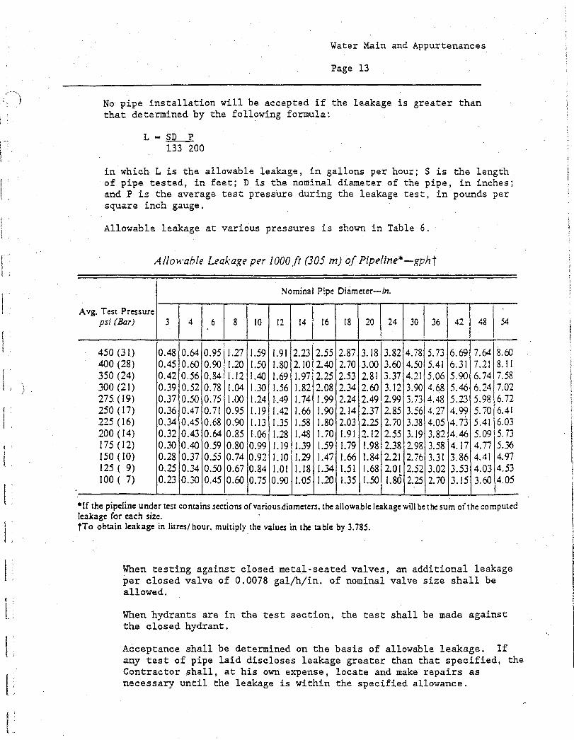
No pipe installation will be accepted if the leakage is greater than that determined by the following formula:
- SD P 133 200
in which L is the allowable leakage, in gallons per hour; S is the length of pipe tested, in feet; D is the nominal diameter of the pipe, in inches; and P is the average test pressure during the leakage test, in pounds per square inch gauge.
Allowable leakage at various pressures is shown in Table 6.
Allowable Leakage per 1000 ft (305 m) of Pipeline-gpht
Avg. Test Pressure psi (Bar)
Nominal Pipe Diameter-in.
4 6 8 10 12 14 16 18 20 24 30 36 42 48 54
450 (31) 0.48 0.64 0.95 1.27 1.59 1.91 2.23 2.55 2.87 3.18 3.82 4.78 5.73 6.69 7.64 8.60 400 (28) 0.45 0.60 0.90 1.20 1.50 1.80 2.10 2.40 2.70 3.00 3.60 4.50 5.41 6.31 7.21 8.11 350 (24) 0.42 0.56 0.84 1.12 1.40 1.69 1.97 2.25 2.53 2.81 3.37 4.21 5.06 5.90 6.74 7.58 300 (21) 0.39 0.52 0.78 1.04 1.30 1.56 1.82 2.08 2.34 2.60 3.12 3.90 4.68 5.46 6.24 7.02 275 (19) 0.37 0.50 0.75 1.00 1.24 1.49 1.74 1.99 2.24 2.49 2.99 3.7.3 4.48 5.23 5.98 6.72 250 (17) 0.36 0.47 0.71 0.95 1.19 1.42 1.66 1.90 2.14 2.37 2.85 3.56 4.27 4.99 5.70 6.41 225 (16) 0.34 0.45 0.68 0.90. 1.13 1.35 1.58 1.80 2.03 2.25 2.70 3.38 4.05 4.73 5.41 6.03 200 (14) 0.32 0.43 0.64 0.85 1.06 .28 1.48 1.70 1.91 2.12 2.55 3.19 3.82 4.46 5.09 5.73 175 (12) 0.30 0.40 0.59 0.80 0.99 1.19 1.39 1.59 1.79 1.98 2.38 2.98 3.58 4.17 4.77 5.36 150 (10) 0.28 0.37 0.55 0.74 0.92 1.10 1.29 1.47 1.66 1.84 2.21 2.76 3.31 3.86 4.41 4.97 125 ( 9) 0.25 0.34 0.50 0.67 0.84 1.01 1.18 1.34 1.51 1.68 2.01 2.52 3.02 3.53 4.03 4.53 100 ( 7) 0.23 0.30 0.45 0.60 0.75 0.90 1.05 1.20 1.35 1.50 1.84:3 2.25 2.70 3.15 3.60 4.05
• If the pipeline under test contains sections of various diameters, the allowable leakage will be the sum of the computed leakage for each size. tTo obtain leakage in litres/ hour, multiply the values in the table by 3.785.
When testing against closed metal-seated valves, an additional leakage per closed valve of 0.0078 gal/h/in. of nominal valve size shall be allowed.
When hydrants are in the test section, the test shall be made against the closed hydrant.
Acceptance shall be determined on the basis of allowable leakage. If any test of pipe laid discloses leakage greater than that specified, the Contractor shall, at his own expense, locate and make repairs as necessary until the leakage is within the specified allowance.
Water Main and Appurtenances
Page 14
All visible leaks are to be repaired regardless of the amount of leakage. At the end of the test period if the amount of water added to the main from the calibrated vessel is less than the allowable leakage, and if the line shows no visible leaks or other failures, that portion of the main tested will be approved.
3.11 CHLORINATION
A. After satisfactory pressure and leakage tests have been made, before placing the newly-laid mains in service. The Contractor shall sterilize the mains by chlorination.
B. Prior to chlorination, the mains shall be flushed to remove dirt and other foreign substances.
C. The mains shall be sterilized by the Contractor under the supervision of the Water Superintendent. The Contractor shall use a manually controlled, vacuum type solution feed chlorinator using a mixture of water and an approved chlorine-bearing compound of known chlorine content, such as calcium hypochlorite. The chlorine shall be introduced into the main through a 3/4-inch corporation stop installed approximately one foot up-stream from the valve at the beginning of the job and shall be tested for residual chlorine at a 3/4-inch corporation stop installed approximately one foot from the downstream valve at the end of the project.
D. Water from an approved source shall be introduced slowly into the main during the application of chlorine. The rate of chlorine mixture flow shall be in such proportion to the rate of water entering the pipe that the chlorine dose entering the mains shall be at least 50 parts per million. When the pipe line has been completely filled with treated water, the main shall be sealed off. Treated water shall be retained in the main for a period of at least twenty-four (24) hours. At the end of the retention period, the chlorine residual at the extremities of the pipe and at other representative points shall be at lest 5 parts per million.
E. Should the first treatment fail to meet the above requirements, the procedure shall be repeated until tests show that, in the opinion of the Water Superintendent, effective sterilization has been accomplished. Excessive additional water used for re-sterilization maybe charged to the contractor at the existing water rate if the Owner so decides.
F. Following sterilization, the chlorinated water shall be flushed from the newly-laid main until such time as the replacement water throughout its entire length shall be equal in quality to that elsewhere in, the system.
G. A representative water sample shall be collected of the potable water now present in the new pipeline by the Contractor under the supervision of the Water Superintendent. This sample shall be taken to a Massachusetts DEQE certified laboratory for a bacteria analysis. The cost associated with the collection and analysis of the sample shall be paid for by the Contractor.
Water Main and Appurtenances
Page 15
H. Special disinfection procedures, such as soaking or swabbing, approved by the Water Superintendent, shall be used in connections to existing mains and where the method outlined above is not practicable.
I. The pressure test shall be conducted at a minimum pressure of 150 psig or 150 percent of working pressure, whichever is greater, and this pressure shall be maintained in accordance with AWWA C600 Specifications. The amount of leakage which will be permitted shall be in accordance with the Specifications for Installation of Ductile Iron Water Mains by AWWA C600.
3.12 GENERAL
A. The pump to be used for testing and chlorination shall be of sufficient be of sufficient size to be able to test to the pressure required and shall contain a by-pass arrangement. Test pump arrangement to be used shall be approved prior to any pressure testing.
B. All valves and hydrants shall be pressure tested during the main pipeline test. Hydrant gate valves shall remain open during the main pressure test. After the pipeline has been pressure tested and accepted the hydrant gate valve shall be closed and the hydrant valve cracked open to release some pressure on the hydrant side of the gate valve. An acceptable test for each hydrant gate valve shall be no loss of pressure in the main line test pressure after each hydrant gate valve is closed.
C. All main line butterfly or gate valves and control valves on any intersecting side streets shall also be tested by the same procedures outlined above as far as practical. The Water Superintendent shall decide if it is impractical to test any one particular valve location. No pressure test shall be considered acceptable until all possible control valves have been tested to insure proper closing and water tightness.
D. The Contractor shall make any taps and furnish all necessary caps, plus, etc., as required in conjunction with testing. He shall also furnish a test pump, gauges and any other equipment required in conjunction with carrying on the hydrostatic tests. He shall at all times protect the new water mains and the existing water mains against the entrance of polluting material.
3.13 CONNECTION TO EXISTING SYSTEM
A. The Contractor shall furnish all necessary labor, tools, joint materials, equipment, etc. to connect new water pipes to existing water pipes with the required proper fittings. Flexible transition couplings used to connect new water pipes to existing water pipes shall be Dresser or approved equal.
B. All connections shall be made at such time and in such a manner as to cause as little interruption in water service as possible.
Water Main and Appurtenances
Page 16
C. Coordination of all such work shall be made with the Douglas Water Department who shall be present when the work is done and shall operate all valves. The Contractor shall notify the Water Department 24 hours in advance of when he plans to connect into the existing water mains.
D. All materials, equipment and labor necessary for the connection of the new water mains to the existing water mains shall be accomplished as directed by the Water Superintendent and all costs shall be paid for by the Contractor.
3.14 SEWER SERVICES AND DRAIN LINES
A. The Contractor shall exercise caution to properly protect the existing sewer services and drain pipes from construction damage. Many of these services are extremely old clay pipe and their specific locations were never properly recorded. It shall be the the Contractor's responsibility to demonstrate that all existing active sewer services and drains are functioning properly after the installation of the proposed water main to the satisfaction of the Owner. All inactive sewer services encountered during the proposed water work shall be cut and plugged with concrete.
B. Damage to existing drains and sewer services shall be repaired or replaced with approved pipe materials of the same size as the existing service at the contractor's expense. Existing slopes and inverts shall be maintained. Pipe joints shall be made using suitable flexible couplings, approved by the Owner. Fernco couplings are an acceptable coupling for sewer service repair. The Contractor shall use same. Concrete mortar joints will not be accepted.
C. If damage occurs to existing house or business sewer services or storm drains and acceptable repairs are accomplished as outlined above, the contractor shall be required to adequately demonstrate to the Owner that the repaired service is functioning normally before any backfill material shall be allowed to be placed.
END OF SECTION
TOWN OF DOUGLAS
WATER 7WASTE WATER 59 CHARLES STREET
. P.O. BOX 624
DOUGLAS, MASSACHUSETTS 01516
(508) 476-2400
SPECIFICATIONS
SANITARY SEWERS
PART 1 GENERAL
1.01 WORK INCLUDED
A. Furnishing pipe for collecting and transporting sewage.
B. Furnishing miscellaneous appurtenances.
C. Installation.
D. Testing.
1.02 REFERENCE STANDARDS
A. ANSI A21.10/AWWA C110 - Grey-Iron and Ductile-Iron Fittings, 3 inch through 48 inch, for Water and Other Liquids.
B. ANSI A21.4/AWWA C104 - Cement-Mortar Lining for Ductile-Iron and Grey-Iron Pipe and Fittings for Water.
C. ANSI A21.51/AWWA C151 - Ductile Iron Pipe.
D. ASTM D3034 - Type PSM Poly(Vinyl Chloride)(PVC) Sewer Pipe and Fittings.
E. ASTM D3212 - Joints for Drain and Sewer Plastic Pipes Using Flexible Elastomeric Seals.
F. ASTM C828 - Low Pressure Air Test for Sanitary Sewers,
G. ASTM D2321 - Underground Installation of Flexible Thermoplastic Sewer Pipe.
PART 2 PRODUCTS
2.01 GENERAL
A. All products included in this section shall conform to the requirements of the standard specifications referenced herein.
B. Pipe size shall be as shown on the approved Drawings or as specified by the Board of Water and Waste Water Commissioners.
C. All pipe materials and methods of jointing shall be as shown on the Drawings.
Sanitary Sewers
Page 2
2.03 SANITARY SEWER
A. Polyvinyl Chloride • (PVC) Pipe - For Gravity Sanitary Sewers
1. Pipe shall be SDR-35, push-on joint conforming with ASTM D3034. Fittings and joints shall comply with ASTM D3139 and ASTM D3212, respectively. The structural integrity of the PVC sanitary sewer shall not be compromised with a 25-foot overburden of trench backfill.
2. Spigot pipe ends shall be supplied with bevels from the manufacturer to ensure proper insertion. Each spigot end shall have an "assembly stripe" imprinted thereon to which the bell end of the mated pipe will extend upon proper jointing of the two pipes. Pipe ends shall be such to permit checking of the rings with a feeler gauge to insure their proper location within the coupling grooves.
3. PVC fittings shall be provided with bell and/or spigot configurations compatible with that of the pipe.
B. All pipe delivered to the job site shall be accompanied by independent testing laboratory reports certifying that the pipe and fittings conform to the above-mentioned specifications. In addition, the pipe shall be subject to thorough inspection and tests, the right being reserved for the Superintendent of Sewers to apply such of the tests specified as may from time to time be deemed necessary.
2.04 DETECTABLE TRACER TAPE
A. The tape shall be installed in accordance with the manufacturer's instructions directly above all PVC pipelines, 1 foot below finished grade.
B. The tape shall be a minimum of 3 inchei wide. The upper face of the tape shall be of a highly ,visible color easily detectable when exposed by digging. The upper face shall carry the warning of the buried plastic sewer main below. The tape shall have•a metalic backing in order that it may be traced by metal or pipe locators.
PART 3 EXECUTION
3.01 GENERAL
A. Pipe and accessories shall be handled in such a manner as to insure delivery on the work site in sound, undamaged condition. Particular care shall be taken not to injure the pipe coating or lining.
B. Any pipe showing a distinct crack with no evidence of incipient fracture beyond the limits of the visible crack, if approved, may have the cracked portion cut off by, and at the expense of, the Contractor before the ripe is laid so that the pipe used is perfectly sound. The cut shall be made in the sound barrel at a point at least 12 inches from the visible limits of the crack.
Sanitary Sewers
Page 3
C. If authorized, cutting of the pipe shall be done in a neat and workmanlike manner without damage to the pipe lining. Unless otherwise authorized by the Superintendent of Sewers, all pipe cutting shall be done by means of an approved type of power cutter. The use of hammer and chisel, of any other method which results in rough edges, chips and damaged pipe, is prohibited.
D. Each pipe section shall be handled into its position in the trench in such manner and by such means required to cause no injury to the pipe or to any property.
E. The Contractor shall furnish slings, straps and/or approved devices to provide satisfactory support of the pipe when it is lifted. Transportation from delivery areas to the trench shall be restricted to operations which can cause no injury to the pipe units.
F. The pipe shall not be dropped from trucks or into the trench.
G. The Contractor shall have on the job site, with each pipe laying crew, all the proper tools to handle and cut the pipe.
H. Flow from existing service connections and main lines shall be maintained at all times by pumping or other approved methods. Under no circumstances will the dumping of raw sewage on private property, in municipal streets or into waterways be allowed.
3.02 CONTROL OF ALIGNMENT AND GRADE
A. Easement and property and other control lines necessary for locating the work as well as elevations and bench marks used in the design of the work are to be shown on approved Drawings by the Board of Water and Waste Water Commissioners.
B. The Contractor shall use this information to set line and use a level or transit to set grade.
C. The Contractor may use a laser beam to assist in setting the pipe provided he can demonstrate satisfactory skill in its use.
D. The use of string levels, hand levels, carpenter's levels or other relatively curved devices for transferring grade or setting pipe are not permitted.
E. During construction, the Contractor shall provide the Sewer Department with all reasonable and necessary materials, opportunities, and assistance for checking previously set stakes making measurements, including the furnishing of one or two rodmen or chairmen as needed for this purpose at intermittent times. He shall not proceed with the work until he has received approval for all necessary construction controls and has been given all instructions that may be necessary for the work to progress. The work shall be done in strict conformity with such controls and instructions.

Sanitary Sewers
Page 4
F. The Contractor shall carefully preserve bench marks, reference points and stakes, and in case of willful or careless destruction by his own men, he will be cliarged with the resulting expense and shall be responsible for any mistakes or delay that may be caused by their unnecessary loss or disturbance.
3.03 EXCAVATION AND BACKFILL
A. The trench bottom shall be straight, free of bumps or hollows and at the proper depth. Any irregularities in the trench bottom shall be leveled off or filled in with 3/4" crushed stone, selected gravel or sand thoroughly tamped as directed by the Superintendent of Sewers.
B. If required, the trench bottom shall be prepared by digging at least 6-inches deeper than pipe grade and backfilling to .proper grade with a selected gravel or sand backfill properly tamped.
C. All unsuitable material shall be removed from the bottom of the trench excavation as directed by the Superintendent of Sewers to the depths ordered. The trench shall be backfilled with an approved gravel backfill material, placed in 6-inch layers, to within 6- inches of proper pipe grade. Each gravel lift shall be thoroughly tamped. A 6-inch layer of selected gravel or sand shall be placed and tamped for proper pipe support.
D. The initial backfilling around the pipe shall be in 6-inch layers properly tamped by hand using standard tamping bars. this shall continue until the backfill is halfway up the pipe. The initial backfilling shall be completed by placing by hand, approved material at least 12-inches over the pipe. The trench is now ready for machine backfill to within 18-inches of the finished surface. No large stones (greater than 6-inches in diameter) will be permitted in the backfill. The final 18" of trench resurfacing will be an approved gravel backfill material placed in 6-inch layers and thoroughly tamped with an approved tamper or power roller.
E. All pavement requiring cutting shall be done by saw cut, pavement breaker or wheel cutter of sufficient size to properly penetrate the total thickness of the existing pavement. Cutting shall be made in a neat, true, straight line with the cut line to be established by chalk line and painting of existing pavement. All cutting methods will be approved by the Superintendent of Sewers before pavement cutting begins.
F. The Contractor shall be required to seek his own legal disposal site for all existing pavement removed, all unsuitable materials removed and all excess spoil removed from the trench work and not used for pipe backfill.
• 3.04 LAYING PIPE
A. Each pipe length shall be inspected for cracks, defects in coating or lining, and any other evidences of unsuitability. Contractor shall excavate a minimum amount of trench and shall backfill trench to within 2 lengths of pipe laying. All trenches shall be backfilled at night.
Sanitary Sewers
Page 5
B Pipe shall be laid in the dry and at no time shall water in the trench be permitted to flow into the pipe.
C The pipe shall then be laid on the trench bedding, and the spigot pushed home. Jointing shall be in accordance with the manufacturer's instructions and appropriate ASTM Standards, and the Contractor shall have on hand for each pipe laying crew, the necessary tools, gauges, pipe cutters, etc., necessary to install the pipe in a workmanlike manner. Pipe laying shall proceed upgrade with spigot ends pointing in the direction of flow.
D Blocking under the pipe will not be permitted except where a concrete cradle is proposed, in which case precast concrete blocks shall be used.
E. After placement of the sand blanket, the pipe shall be checked for line and grade and any debris, tools, etc., shall be removed.
F. The pipe shall not be driven down to grade by striking it with a shovel handle, timber, rammer, or other unyielding object. When each pipe has been properly bedded, enough of the backfill material shall be placed and compacted between the pipe and the sides of the trench to hold the pipe in correct alignment.
G. Branches and fittings shall be laid by the Contractor as indicated on the approved drawings, and/or as directed by the Superintendent of Sewers. Open ends of pipe and branches shall be closed with PVC caps secured in place with premolded gasket joints or as directed by the Superintendent of Sewers.
H. If inspection of the pipe is satisfactory, the Contractor may then refill or backfill the remainder of the trench in accordance with Paragraph 3.03.
I. At any time that work is not in progress, the end of the pipe shall be suitably closed to prevent the entry of animals, earth, etc.
J. At the end of each day's work or at intervals deemed appropriate the pipe will be inspected for alignment with lamps or mirrors. Unsatisfactory work shall be dug up and reinstalled.
3.05 BUILDING SEWERS
A. General
1. Where feasible, a separate and independent building sewer shall be provided for every building. When one building stands to the rear of another on an interior lot and no building sewer is available or can be constructed, the front building sewer may be extended to the rear building provided that a manhole is constructed at the junction of the rear building sewer and the front building.
2. Where the structure is a duplex, a separate connection will be installed for each side.

Sanitary Sewers
Page 6
3. Where the structure is a condominium, a maximum of six units will be allowed on a single connection. When the building has more than six units, a second connection for the remaining units will be installed.
4. Old building sewers may be used in connection with new buildings only when they are found, on examination and test by the. Board, to meet all requirements of this ordinance.
5. The size, slope, alignment, materials of construction of a building sewer, and the methods to be used in excavating, placing of the pipe, jointing, testing, and backfilling the trench shall all conform to the requirements of applicable building and plumbing code's.
6. Whenever possible, the building sewer shall be brought to the building at an elevation below the basement floor. In all buildings in which any building drain is too low to permit gravity flow to the public sewer, sanitary dewage carried by such building drain shall be lifted by a means approved by the Board and discharged to the building sewer.
B. Materials and Workmanship
1. Pipe and fittings to be used in the work shall be either PVC or cement lined ductile iron, 6 inches or more in diameter. Services 4 inches in diameter will be allowed only under special conditions, as approved by the Superintendent of Sewers. Allowable lengths of pipe to be used will be determined by the Board of Sewer Commission.
2. In general, sewer services will not be allowed to have more than two (2) angle points, or a total angular deviation of 180 degrees. Cleanouts shall be installed at each deflection.
3. All services shall be laid in an envelope of 3/4" washed stone with not less than 6 inches of said material all around the barrel of the pipe.
4. All pipe and fittings shall be laid to a minimum slope of 1/4 inch per foot.
5. Line and grade of the pipe and fittings shall be controlled by the use of batter boards and string lines set for this purpose. Batter shall not exceed a distance of 30 feet apart unless otherwise directed by the Superintendent of Sewers.
6. In general, trenches shall be excavated from the end of the existing sewer service to its point of connection to the building plumbing outlet before backfilling and pipe beyond the gravel envelope.
7. Services in excest—of 50 feet in length are subject to review and such other requirements as may be found necessary to assure a functional connection.
Sanitary Sewers
Page 7
8. In new construction, and where practicable in existing buildings when the common sewer is sufficiently deep, service shall be laid directly, without'deflections from the house plumbing vent stack to the connection provided at the common sewer.
9. Tunnelling will not be allowed unless special permission for same is given.
10. Connection made to the building plumbing system, shall be upstream of any septic tanks or cesspools.
11. Pipe and fittings shall not be backfilled beyond 3/4" washed stone envelope until the work is inspected.
12. Drainlayers shall be responsible for all defects in materials and workmanship for a period of one year following completion os the sewer service installation.
13. Upon connection of the building plumbing system to the common sewers, existing septic tanks and cesspools shall be pumped dry then completely filled with suitable earth materials.
14. Connection shall not be cut into common sewers without permission from the Board.
3.06 TESTING
A. General
1. Leakage tests shall be conducted on all pipes installed. All tests shall be witnessed by the Sewer Department. The Contractor shall supply all plugs, pumps, weirs, water trucks, etc., necessary to conduct the tests. Should the work fail the leakage tests, corrective action shall be taken by the Contractor. If directed, by the Superintendent of Sewers, the Contractor shall dig up and re-lay the failed section.
2. In general, the use of sealants, applied from the inside of the pipe, will not be approved.
3. Flush all piping systems with water prior to testing.
4. Testing forms which indicate all testing information and results shall be submitted to the Sewer Department.
Sanitary Sewers
Page 8
B. Sanitary Sewer Pipe Testing with All Service Connections Capped
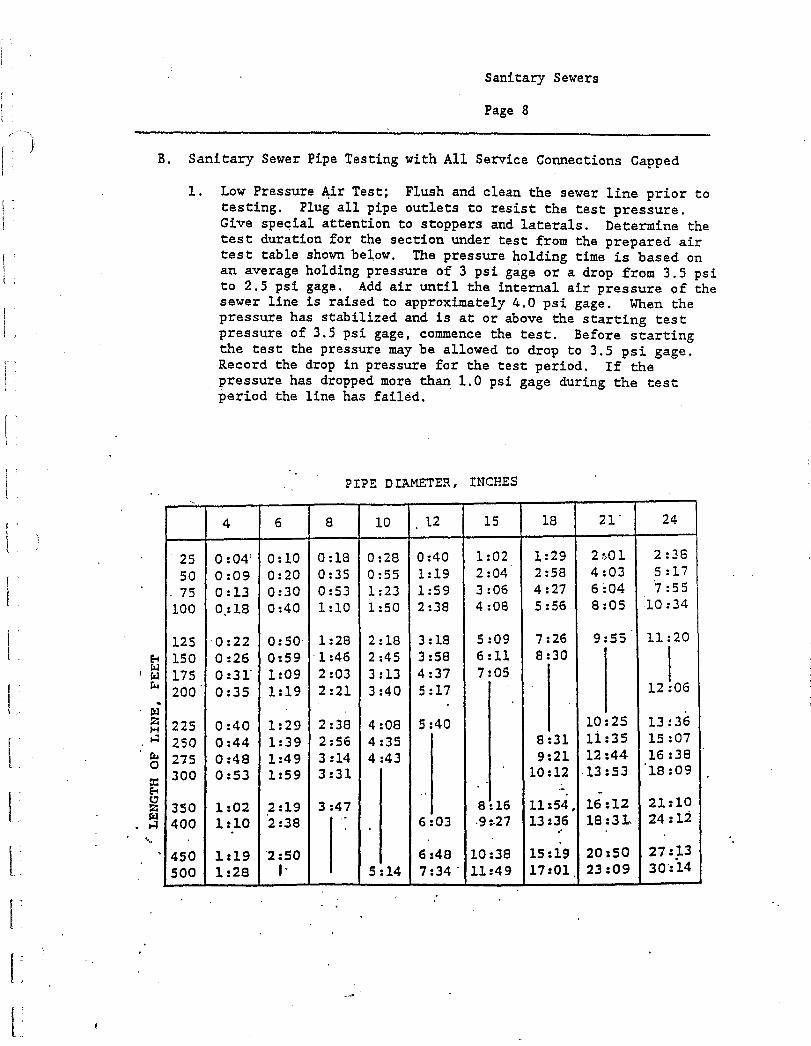
1 Low Pressure Air Test; Flush and clean the sewer line prior to testing. Plug all pipe outlets to resist the test pressure. Give special attention to stoppers and laterals. Determine the test duration for the section under test from the prepared air test table shown below. The pressure holding time is based on an average holding pressure of 3 psi gage or a drop from 3.5 psi to 2.5 psi gage. Add air until the internal air pressure of the sewer line is raised to approximately 4.0 psi gage. When the pressure has stabilized and is at or above the starting test pressure of 3.5 psi gage, commence the test. Before starting the test the pressure may be allowed to drop to 3.5 psi gage. Record the drop in pressure for the test period. If the pressure has dropped more than 1.0 psi gage during the test period the line has failed.
PIPE DIAMETER, INCHES
4 6 8 10 . 1.2 15 18 21' 24
25 0:04 0:10 0:18 0:28 0:40 1:02 1:29 2 01 2:38
50 0:09 0:20 0:35 0:55 1:19 2:04 2:58 4:03 5:17
75 0:13 0:30 0:53 1:23 1:59 3:06 4:27 6:04 7:55
100 0:18 0:40 1:10 1:50 2:38 4:08 5:56 8:05 10:34
125 0:22 0:50 1:28 2:18 3:18 5:09 7:26 9:55 11:20
150 0:26 0:59 1:46 2:45 3:58 6:11 8:30
I 175 0:31 1:09 2:03 3:13 4:37 7:05
200 . 0:35 1:19 2:21 3:40 5:17 •
12 06
225 0:40 1:29 2:38 4:08 5:40 10 25 13:36
250 0:44 1:39 2:56 4:35 8:31 11 35 15:07
275 0:48 1:49 3:14 4:43 9:21 12.44 16:38
300 0:53 1:59 3:31 10:12 13:53 '18:09
350 1:02 2:19 3:47 8:16 11:54, 16:12 21:10
400 1:10 2:38 6 03 .9:.27 13:36 18:31 24:12
450 1:19 2:50 6:48 10:38 15:19 20:50 27:13
500 1:28 I- 5:14 7:34 ' 11:49 17:01 , 23:09 30:14

Sanitary Sewers
Page 9
2 Infiltration: When the groundwater is one foot or more above the crown of the pipe at the upper end of the section to be tested, an infiltration test shall be made. The upper end of the section to be tested shall be plugged and a V-notch weir of appropriate size shall be fitted into the lower end so as to prevent leakage around the weir plate. Commercially manufactured weir plates made and calibrated for the purpose may be used. The leakage infiltration shall not exceed 200 gallons per inch of pipe diameter per mile of pipe per day.
3 Deflection Test: Optional devices for testing include calibrated television, photography, properly sized "GO-NO-GO" mandrel, sewer ball or deflectometer. Maximum allowable pipe deflection shall be 7-1/2% Pipe deflection testing shall not be performed until the pipeline has been under soil backfill for a minimum of six months.
4. The sewers shall be tested after building connections are installed to the property line.
5. Should the sections under test fail to meet the requirements, the Contractor shall do all work of locating and repairing leaks and retesting as required without additional compensation. A plan of the method of repairing any leaks that are found shall be submitted to the Superintendent of Sewers for approval.
3.07 PROXIMITY TO WATER MAINS
A. Whenever possible, sewers shall be laid with a minimum of 10 feet horizontal separation between the sewer And potable water lines. Should a lateral separation of 10 feet not be possible, the following methods of protection must be employed:
1. Lay sewer and water main in separate trench.
2. Lay the sewer and water main in same trench with the water main At one side on a bench of undisturbed earth.
3. In both above cases, the water main invert shall be 18 inches above the sewer crown.
B. Whenever sewers must cross under water mains, the sewer shall be laid at such an elevation that the top of the sewer is at least 18 inches below the bottom of the water main. When the elevation of the sewer cannot be varied to meet the above requirements, the water main shall be relocated to provide this separation or reconstructed with mechanical-joint pipe for a distance of 10 feet on each side of the sewer. One full length of water main should be centered over the sewer so that both joints will be as far from the sewer as possible.
Sanitary Sewers
Page 10
C. When it is impossible to obtain horizontal and/or vertical separation as stipulated above, both the water main and sewer shall be constructed of mechanical-joint cement lined ductile iron pipe or other material based on watertightness and structural soundness. Both pipes shall be pressure tested by an approved method to assure watertightness or both pipes shall be encased in concrete. The sewer shall not be located above the water main.
END OF SECTION
Castings
Page 1
CASTINGS
PART 1 GENERAL
1.01 WORK INCLUDED
A. Furnishing sewer manhole frames and covers.
B. Installation.
1.02 QUALITY CONTROL INSPECTION
A. All castings shall be subject to a hammer inspection by the Superintendent of Sewers. Castings rejected upon delivery to the site shall be marked as such and removed from the site. All castings damaged after delivery or after installation shall be removed and replaced at the Contractors expense.
1.03 REFERENCE STANDARDS
A. ASTM A48 - Grey Iron Castings.
PART 2 PRODUCTS
2.01 GENERAL
A. The castings shall be of good quality, strong, tough, even-grained cast iron, smooth, free from scale, lumps, blisters, sandholes and defects of every nature which would render them unfit for the service for which they are intended. Contact surfaces of covers and frame seats shall be machined at the foundry, before shipment to prevent rocking of covers in any orientation. All castings shall be thoroughly cleaned and subject to a careful hammer inspection.
B. Castings shall be at least Class 30 conforming to the ASTM A48.
C. Before being shipped from the foundry, castings shall be sandblasted and given two coats of coal-tar-pitch varnish, applied in a satisfactory manner so as to make a smooth coating, tough, tenacious, and not brittle or with any tendency to scale off. Coatings damaged in transit or handling shall be repaired by the contractor to the satisfaction of the Superintendent of Sewers.
D. All castings shall be heavy duty suitable for H-20 loadings.
E. Manhole frames and covers shall provide 24 inch diameter clear opening. The cover shall have the word "SEWER" cast into a diamond design top surface, weigh at least 475 lbs., and be designed so that loads are transmitted directly onto the vertical sides of the frame.
Castings
Page 2
PART 3 EXECUTION
' 3.01 SETTING FRAMES AND•COVERS •
A. Frames shall be set with the tops conforming accurately to the grade of the pavement or finished ground surface. Frames shall be adjusted to grade with a precast concrete grade ring or a maximum of 3 courses of mortared red sewer brick. Exterior of sewer brick shall be plastered with mortar. Frames shall be set concentric with the top of the masonry and in a full bed of mortar so that the space between the top of the manhole masonry and the bottom flange of the frame shall be completely filled and made watertight. A thick ring of mortar extending to the outer edge of the masonry shall be placed all around and on the top of the bottom flange. The mortar shall be smoothly finished and have a slight slope to shed water away from the frame.
B. Manhole covers shall be left in place in the frames upon completion of other work at the manholes.
END OF SECTION
Precast Concrete Manholes
Page 1
PRECAST CONCRETE MANHOLES
PART 1 GENERAL
1.01 WORK INCLUDED
A. Furnishing precast concrete manholes and appurtenant materials and equipment.
B. Installation.
C. Leakage Testing.
1.02 QUALITY CONTROL INSPECTION
A. The quality of all materials, the process of manufacture and the finished sections shall be subject to inspection by the Superintendent of Sewers. Such inspection may be made at the place of manufacture, and or on the work site after delivery. Sections shall be subject to rejection at any time on account of failure to meet any of the Specification requirements, even though sample sections may have been accepted as satisfactory at the place of manufacture. Sections rejected after delivery to the site shall be marked for identification and shall be removed from the site at once. All sections which have been damaged after delivery will be rejected, or if already installed, shall be repaired or removed and replaced entirely at the Contractor's expense.
B. All sections shall be inspected for general appearance, dimensions, soundness, etc. The surface shall be dense, close-textured and free of blisters, cracks, roughness and exposure of reinforcement.
C Imperfections may be repaired, subject to the approval of the Superintendent of Sewers, after demonstration by the manufacturer that strong and permanent repairs result. Repairs shall be carefully inspected before final approval. Cement mortar used for repairs shall have a minimum compressive strength of 4,000 psi at the end of 7 days and 5,000 psi at the end of 28 days when tested in 2 inch cubes stored in the standard manner. Epoxy mortar may be utilized for repairs, subject to the approval of the Superintendent of Sewers.
1.03 REFERENCE STANDARDS
A. ASTM C32 - Sewer and Manhole Brick (Made from Clay or Shale).
11: ASTM C91 - Masonry Cement.
C. ASTM C144 - Aggregate for Masonry Mortar.
D. ASTM C150 - Portland Cement.
E. ASTM A185 —Welded Steel Wire Fabric for Concrete Reinforcement.
V ACTM rnni

1.]
Precast Concrete Manholes
Page 2
G. ASTM C270 - Mortar for Unit Masonry.
H. ASTM C387 - Packaged Dry COmbined Materials for Mortar and Concrete.
I. ASTM C478 - Precast Reinforced Concrete Manhole Sections.
J. ASTM C443 - Joints for Circular Concrete Sewer and Culvert Pipe, Using Rubber Gaskets.
PART 2 PRODUCTS
2.01 GENERAL
A. Manholes shall be precast of reinforced concrete and shall conform to ASTM C478.
B. Reinforcing shall be welded wire fabric conforming to ASTM A185.
C. Cement shall be Type II Portland Cement conforming to ASTM C150.
D. The manhole structure including all component parts shall be capable of withstanding loads of 8 tons (H-20) without failure or leakage.
E. All precast sections and bases shall have the date of manufacture and the name or trademark of the manufacturer impressed or indelibly marked on the inside wall.
2.02 PRECAST MANHOLE SECTIONS
A. Cone sections shall be eccentric - see miscellaneous detail sheet(s).
B. In lieu of a cone section, when manhole depth is less than 6 feet, a reinforced concrete slab cover shall be used having an eccentric entrance opening and capable of supporting H-20 loads.
C. All precast structures shall conform to applicable portions of ACI 318
D. The base section shall be monolithic to a point at least 6 inches above the openings cast to receive the sewer lines. In the cast of an outside drop manhole, the opening shall be a minimum of 6 inches from any joint.
2.03 MANHOLE JOINTS AND PIPE SEALS
A. Horizontal joints between sections of the precast manholes shall be as shown on the Drawings and shall have a mastic-like sealant such as Ram-Nek, Kent Seal No. 2 or a butyl rubber joint gasket conforming. to ASTM C443. All horizontal joints shall be watertight in accordance with the testing requirements of this Section.

Precast Concrete Manholes
Page 3
B. Pipe to manhole joints shall be a cast-in-place flexible rubber boot or as approved by the Superintendent of Sewers. Nonshrinking mortar or grout is not acceptable: Pipe to manhole connections and joints shall be watertight in accordance with the testing requirements of this Section.
2.04 BRICK
A. ASTM C32, Grade SS.
2.05 MORTAR
A. Masonry Cement: ASTM C91.
B. Aggregate for Masonry Mortar: ASTM C144.
C. Hydrated Lime for Masonry Purposes: ASTM C207.
D. Mortar for Unit Masonry: ASTM C270, Type S. E. Portland Cement: ASTM C150, Type II.
F. Premixed Materials: ASTM C387.
2.07 MISCELLANEOUS COMPONENTS
A. Manhole steps:
1. Embedment:
a. Friction fit (normally a plant installation): 1) 3-1/8 inch penetration 2) 1-13/32 inch taper to 1-5/32 inch diameter. 3) Use set pin during initial cure to assure hole is not
deformed. 4) Seat with impact hammer.
b. Mechanical bond (field installation only) 1) 1-1/2 inch diameter, 3-1/8 inch penetration by concrete
drill. 2) Use a jig to insure, proper vertical and horizontal
alignment of receiving holes. 3) Epoxy
2. Plastic manhole rungs shall comply with all dimensional and structural requirements of O.S.H.A. (most recent publication). a. Setting: 12 inches center to center vertical distance,
unless otherwise indicated on the Drawings.
b. Integral foot stops.
c. Live load 300# applied point loading at maximum stress. Pull-out 2500# applied center of rung.
B. Bedding material shall consist of screened gravel or crushed stone.

Precast Concrete Manholes
Page 4
PART 3 EXECUTION
3.01 EXCAVATION AND BACKFILLING'
A. Excavation, backfilling and compaction shall be performed with material as specified.
3.02 INSTALLATION OF MANHOLE BASES AND SECTIONS
A. Sections shall not be shipped or manhole rungs subjected to loading until the concrete has attained a compressive strength of 3000 psi or until 5 days after fabrication and/or repair, whichever is the longer.
B. Precast bases shall be placed on a 12 inch layer of compacted bedding material approved by the Superintendent of Sewers. The excavation shall be properly dewatered while placing bedding material and setting the base.
C. Inlet and outlet stubs shall be connected and sealed in accordance with the manufacturer's recommended procedure, and as shown on the Standard Details.
D. Barrel sections and cones of the appropriate combination of heights shall then be placed, using manufacturer's recommended,procedure for sealing the horizontal joints. Joints shall be bitumastic sealant unless otherwise approved by the Superintendent of Sewers.
E. A leakage test shall then be made as described below in this section.
F. Upon successful completion of the leakage test all joints will be painted.
G. The inverts and the shelf shall be constructed of brick masonry.
H. The frame and cover shall be placed on the top of the manhole or some other approved means shall be provided to prevent accidental entry by unauthorized persons, children, animals, etc.., until the Contractor is ready•to make final adjustment to grade.
3.03 MIXING MORTAR
A. ASTM C270.
3.04 BRICK MASONRY
A. Only clean bricks shall be used in brickwork for grade adjustment and manhole inverts. The brick shall be moistened by suitable means, as directed, until they are neither so dry as to absorb water from the mortar nor so wet as to be slippery when laid.
B. Each brick shall be laid in full bed and joint of mortar without requiring subsequent grouting, flushing, or filling, and shall be thoroughly bonded.
Precast Concrete Manholes
Page 5
C. Brick masonry shall be protected from too rapid drying by the use of burlap kept moist, or by other approved means, and shall be protected from the.weather'and frost, all as required.
D. All masonry joints which are exposed to view shall be examined to locate cracks, pointed up and filled with mortar. Where necessary, the joints shall be cut out and repointed with setting mortar of the same color as that of the original and adjoining work.
3.05 LEAKAGE TESTS FOR SEWER MANHOLES
A. Leakage tests shall be made by the Contractor and observed by the Sewer Department on each manhole. The test shall be an exfiltration test made as described below.
B. Water Test
1 After the manhole has been assembled in place, all lifting holes shall be filled with an approved nonshrinking mortar. The test shall be made prior to placing the shelf and invert and before filling and pointing the horizontal joints. If the ground water table has been allowed to rise above the bottom of the manhole, it shall be lowered for the duration of the test. All pipes and other openings into the manhole shall be suitably plugged and the plugs braced to prevent blowout.
2 The manhole shall then be filled with water to the top of the cone section. If the excavation has not been backfilled and observation indicates no visible leakage, that is, no water observed moving down the surface of the manhole, the manhole may be considered to be satisfactorily watertight. If the test, as described above, is unsatisfactory as determined by the Superintendent of Sewers, or if the manhole excavation has been backfilled, as per the direction of the Superintendent of Sewers, the test shall be continued. A period of time may be permitted if the Contractor so wishes to allow for absorption. At the end of this period, the manhole shall be refilled to the top of the cone, if necessary, and the measuring time of at least 8 hours begun. At the end of the test period, the manhole shall be refilled to the top of the cone, measuring the volume of water added. This amount shall be extrapolated to a 24 hour rate and the leakage determined on the basis of depth.• The leakage for each manhole shall not exceed 1 gallon per vertical foot for a 24 hour period. If the test fails this requirement, but the leakage does not exceed 3 gallons per vertical foot per day, repairs by approved methods may be made as directed by the Superintendent of Sewer to bring the leakage within the allowable rate of 1 gallon per vertical foot per day. Leakage due to a defective section or joint or exceeding the 3 gallon per vertical foot per day, shall be cause for the rejection of the manhole. It shall be the Contractor's responsibility to uncover the manhole as necessary and to disassemble, reconstruct or replace it as directed. The manhole shall then be retested and, if satisfactory, interior joints shall be filled and painted.
Precast Concrete Manholes
Page 6
3. The test shall be conducted before backfilling around the manhole. However, if the Superintendent of Sewers permits and the Contractor•elects*to backfill prior to testing, for any reason, it shall be at the Contractor's risk and it shall be incumbent upon the Contractor to determine the reason for any failure of the test. No adjustment in the leakage allowance will be made for unknown causes such as leaking plugs,
1
absorption, etc., i.e., it will be assumed that all loss of water during the test is a result of leaks through the concrete. Furthermore, the Contractor shall take any steps necessary to assure the Sewer Department that the water table is below the bottom of the manhole throughout the test.
4. If the groundwater table is over the highest joint in the manhole, and if there is no leakage into the manhole such a test can be used to evaluate the watertightness of the manhole. However, if this procedure is found unacceptable, the Contractor shall lower the water table and carry out the test as described herein before.
5. The allowable infiltration/exfiltration rate shall be zero gallon per vertical foot per day when the manhole is within 75 feet of wells for individual homes and 125 feet of wells for two homes and 200 feet of wells for three or more homes.
C. Vacuum Test:
1. The vacuum test may be performed on manholes, completely constructed, with inlet and outlet pipes in place. Test shall be conducted before any backfilling begins. Any material around the base section shall be removed to expose the entire side of the manhole. Plug pinholes and horizontal seams with a non- shrinking mortar.
2. Brace the inlet and outlet pipes to prevent movement during the test. Use air inflated plugs in good condition.
3. The vacuum test shall be performed using equipment approved by the Superintendent of Sewers. The equipment shall be in good operating condition. All gauges shall not have any broken glass or other visible abnormalities. The test shall be performed by trained personnel familiar with the equipment and the,test.
4. The test shall have a minimum duration of two minutes. The vacuum shall be pumped down to 10 inches of mercury on an approved gauge, and held. At the time the removal of air is stopped, the test time shall begin.
Precast Concrete Manholes
Page 7
5. Any manhole that has a vacuum drop to nine inches of mercury or less, within the following time intervals, shall have failed the test.
0 - 10 ft. deep: less than 2 minutes. 10 - 15 ft. deep: less than 2-1/2 minutes. 15 - 20 ft. deep: less than 3 minutes. over 20 ft. deep: less than T.
Calculations for manholes deeper than 20 feet: T — 0.085 DK/Q
T — Time of pressure drop in seconds. K — 0.000419 DL; but not less than 1.0. Q 0.0015 ft3/min/ft2 of area. D Nominal manhole diameter in inches. - L — Depth of manhole in feet.
END OF SECTION
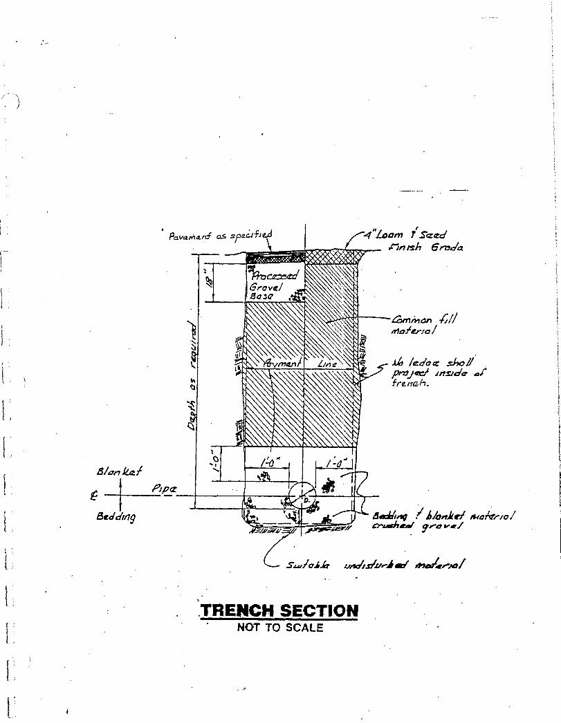
Pavarylami as s ed 4".1.aom cin ish 6 mice
4;eni1ar) -4//
maAerro/
ledo .sha pricer/ inside f re ma h.
L
C4
B/au kg!
I Pipe.
Search/1g , . Ifiechitiv h /onkel 4401 / crushed/
trAciAryi.u..-.4 ma' mrestert,ai
• TRENCH SECTION •
' NOT TO SCALE

silo,* xr tict to • c
Pio/clap IP 95A PPOA Zif
rOad 40 L44 pug
4,5 vrp. PP cc' vpd t;:ti p,idarl4/Cfpl7/5
vow I .47)/112)g 55 0/47a,67 /Lk7 wisr)
.4aP/nos- .77.5 pvo •wcw," w.Aw
Drag syst."71,,CL7 /50772,1/
SW46VaY /P54 v, iir(g(i`r Rwor vry POW
2ywd two:, 115=4:1•:10
0 -
*010745 yoi,r
pivots areJ-7.esPnr Adel! PO PAi/x17
714mor /ysy-tm,b9A1
ai'' 7 cyciow • MA= ra7A 191 *0 ..14e0f411/0 ruys .0/d 10 WI, 3 1."77 C) EX 014 11
dr-41P.'vkV rt-v- -' • .50 $5,12, / faz177,45/
synx.• fn/Pp'
- /yr prt vva7 Jo
/my (11 f4715, y (477.,
'Cr OVOrj 7 Nat i 55,7 Crly
10/5119 DO, pasmnpippefi
9/7F Wcfr 17Araf, fine C'JWG7
21/9411")S
711/ 27
*1/9-KF
40/742-16 higiey
AAA of .r14/471.ed al yvoiy
31V3S 01 ION
31OHNVIN 313E101400 1$1/03LIci
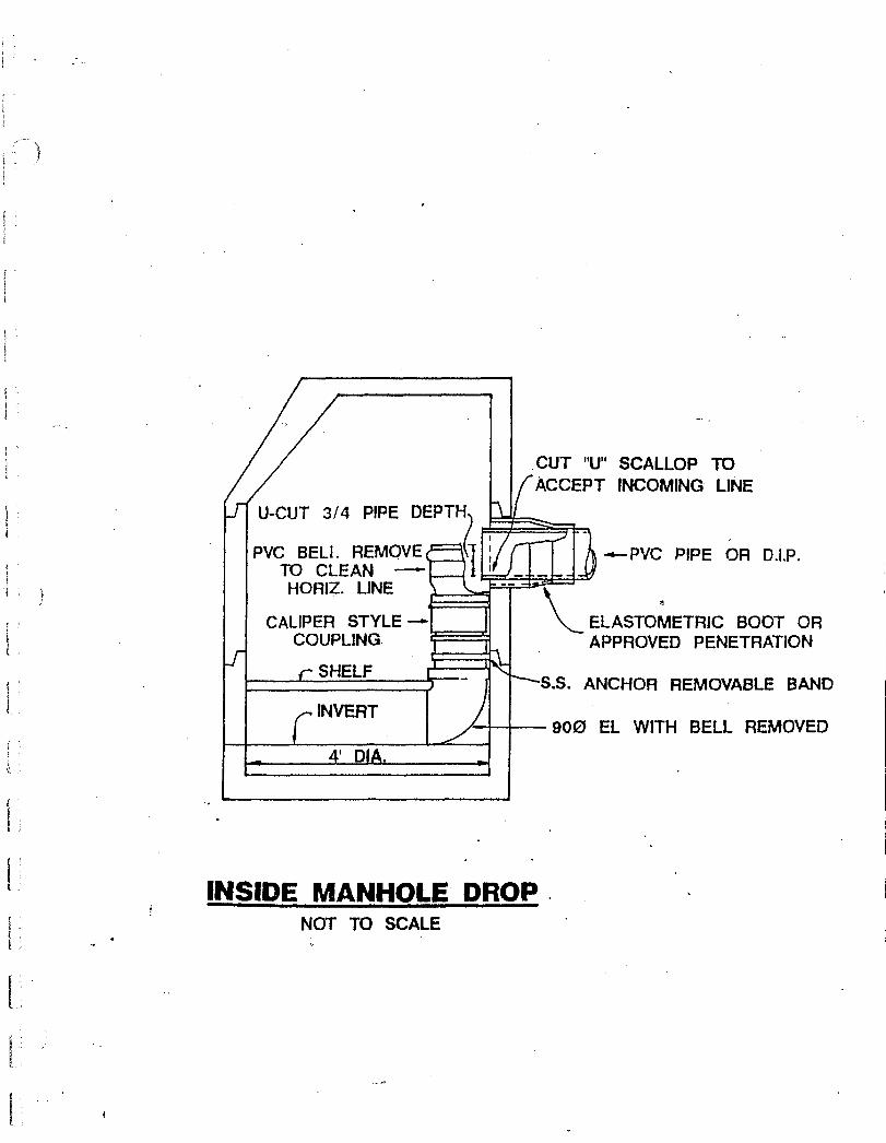
PVC BELL REMOVE TO CLEAN
LINE
CALIPER STYLE --COUPLING.
r SHELF
r. INVERT
4' DIA.
+-PVC PIPE OR DIP.
ELASTOMETRIC BOOT OR APPROVED PENETRATION
S.S. ANCHOR REMOVABLE BAND
900 EL WITH BELL REMOVED
CUT "U" SCALLOP TO ACCEPT INCOMING LINE
U-CUT 3/4 PIPE DEPTH
INSIDE MANHOLE DROP . NOT TO SCALE
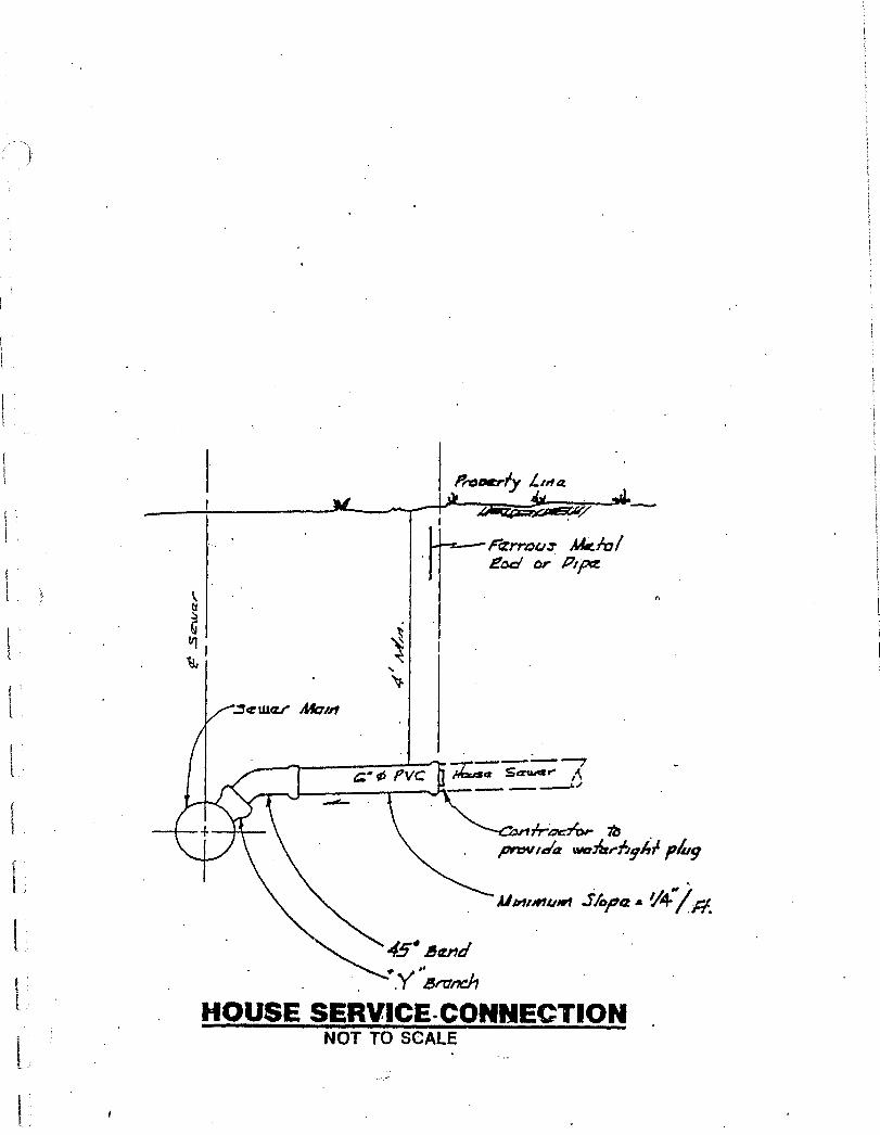
Proverey Lea
rizrrouz AEA,/ Pod or Ape
=cum.- Awe
Auset Sauer r" A
provaa tvoiixebythi l plug
Ahruour•ri Skim
4.5.15end
• HOUSE SERVICE.CONNECTION NOT TO SCALE
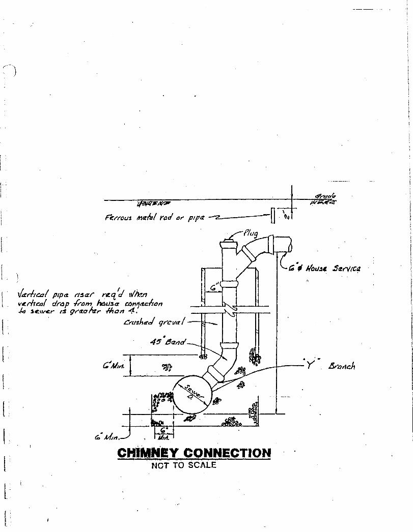
sr: GIA/oi.‘
cfrtre4r
Fittous roc" or "actF] .
tt\i
P/u9
4.111
a'of //wig .Scervic4t
pipes riscrt racild vet-heal drop kam /dim com 42
ptchan 14ZtVCrs e i46an 4.
eraiipri grrval
• 45.15arial
4144(1ArreAr
Braelcit
CHIMNEY CONNECTION NOT TO SCALE