Embed Size (px)
Citation preview
8/2/2019 Waterford Tender Design
http://slidepdf.com/reader/full/waterford-tender-design 1/35
ASL
12
Process Design for the
Waterford city Waste
Water Treatment PlantBid for contract Nr. 5
Activated Sludge Limited

8/2/2019 Waterford Tender Design
http://slidepdf.com/reader/full/waterford-tender-design 2/35
Activated Sludge limited
Process Design for the Waterford city Waste Water Treatment Plant
1
Page 1 of 34
EXECUTIVE SUMMARY Activated sludge limited (ASL) is grateful to the Waterford city council for the opportunity to
participate in the bidding process for the Waterford city waste water treatment plant (Contract Nr
5).
Activated sludge limited was incorporated in 1982 as small civil engineering consulting company. We
are pleased to note that we previously designed and build a number of works for Waterford city
council such roads, sewerage and the city council building which we completed ahead of schedule in
1991. Our works therefore speak for themselves.
Like Waterford city, we have grown in leaps and bounds. We are now a publicly traded company
quoted on the London stock exchange (LSE: ASL). We have interests and expertise in virtually all
fields of engineering.
ASL is the first company in the UK to extract struvite, a slow-release nitrogen and phosphorus based
fertilizer from sewage digestate liquor. This novel process is being piloted at the Birmingham water
treatment plant which we designed and built. The plant is already saving money on environmental
remediation and the government has just approved struvite for sale as a save environmentally
friendly fertilizer. Struvite recovery is built into this design we are submitting for the Waterford
scheme.
Using our patented technology, we are ahead of the competition in our efficiency at combining
primary and secondary sludge thickening with digestate sludge drying in the same facility. In this
way, we have saved our clients millions of pounds in operational costs.
Our general design principles lay emphasis on functionality, sustainability and optimum return on
investment.
We have assigned our director of engineering design, Dr Nigel Horan to oversee the implementation
of this project. Dr Horan is renowned expert on waste water engineering with a lot of publications to
his name. His appointment underscores the value we attach to this bid.
Given that as a company, we have grown with the city of Waterford, we look forward to another
opportunity to cement this long-term relationship we have had with Waterford city.

8/2/2019 Waterford Tender Design
http://slidepdf.com/reader/full/waterford-tender-design 3/35
Activated Sludge limited
Process Design for the Waterford city Waste Water Treatment Plant
2
Page 2 of 34
Eng. Adamu Onakpa
BSc. MsE. Ceng.
Senior Process Design Engineer
Activated sludge limited

8/2/2019 Waterford Tender Design
http://slidepdf.com/reader/full/waterford-tender-design 4/35
Activated Sludge limited
Process Design for the Waterford city Waste Water Treatment Plant
3
Page 3 of 34
ContentsEXECUTIVE SUMMARY ............................................................................................................................ 1
INTRODUCTION ....................................................................................................................................... 4
General Requirements from the Tender document ............................................................................... 5
INFLUENT ............................................................................................................................................ 5
Nutrient Removal .............................................................................................................................. 11
PERFORMANCE STANDARDS............................................................................................................. 11
PROCESS DESIGN REQUIREMENTS .................................................................................................. 12
PRELIMINARY TREATMENT ................................................................................................................... 18
INLET WORKS .................................................................................................................................... 18
PRIMARY TREATMENT .......................................................................................................................... 20
Tank shell design ............................................................................................................................... 20
Design of tank internals .................................................................................................................... 21
THE ACTIVATED SLUDGE PROCESS DESIGN .......................................................................................... 22
Design calculations............................................................................................................................ 23
SECONDARY TREATMENT TANKS .......................................................................................................... 27
Tank design calculations ................................................................................................................... 27
Design of tank internals .................................................................................................................... 28
SLUDGE ARISINGS ................................................................................................................................. 28
Sludge storage prior to digestion ...................................................................................................... 29
Sludge thickening and dewatering .................................................................................................... 29
MESOPHILIC ANAEROBIC DIGESTION ................................................................................................... 30
Design of the anaerobic digester ...................................................................................................... 30
Gas Generation ................................................................................................................................. 30
Gas storage ....................................................................................................................................... 31
CHP Power output............................................................................................................................. 31
Dewatering ........................................................................................................................................ 31
Nutrient recovery .............................................................................................................................. 32
CONCLUSION ......................................................................................................................................... 33
REFERENCES .......................................................................................................................................... 34
8/2/2019 Waterford Tender Design
http://slidepdf.com/reader/full/waterford-tender-design 5/35
Activated Sludge limited
Process Design for the Waterford city Waste Water Treatment Plant
4
Page 4 of 34
INTRODUCTIONThis bid document is intended to communicate the technical process design for the water form
waste water plant. Each unit process is preceded by a brief explanation followed by calculations
used to arrive at each design specification.
It begins with a complete summary of design requirements and everything is extracted from the
tender document. Other parameters not contained in the tender are derived from generally
accepted engineering standard tables.
The plant is designed to treat projected incremental load input up to the 2025 with a maximum flow
rate of 1.687m3/s. the design BOD and TSS loads are 11,436Kg/d and 8005Kg/d respectively. Both
primary and secondary sludges are to be thicked to 6% dry solids. The dried sludge is to be 23% dry
solids.
The CHP plant has a designed power output of 4.1MW. A single element of the design is at the
minimum up to the tender requirement and to compy with stringent environmental regulations
8/2/2019 Waterford Tender Design
http://slidepdf.com/reader/full/waterford-tender-design 6/35
Activated Sludge limited
Process Design for the Waterford city Waste Water Treatment Plant
5
Page 5 of 34
General Requirements from the Tender document
The following information provided in the Tender has been used to design the Plant as specified:
INFLUENT
The Works shall be designed for the projected domestic and commercial waste water inputs for the
Year 2025 with an allowance for industrial wastewater, infiltration and storm water.
The design flows have been calculated as multiples of dry weather flow (DWF) using the formula
below:
DWF = (P x Q/1000) + C + E (m3/d)
Where:
P - Resident population
Q- Per capita sewage discharge including infiltration, litres/day
C-commercial flow rate, m3/day
E- Industrial waste water flow rate, m3/day
The estimated resident populations for the catchment area of the Waste Water Treatment
Plant is as follows:
Year 2005 51,640
Year 2025 67,905
The domestic flow arriving at the waste water treatment plant has been calculated using the
following criteria from the tender document.
Per capita sewage discharge 150 litres/h/d
Allowance for infiltration 50 litres/h/d
Commercial flow 24 litres/h/d (i.e. 16% of per capita above)
The industrial contribution comprises the existing estimated industrial flow of 5,424 m 3/d (which is
taken to be the loading for year 2005) and the future industrial loading of 12,254 m
3
/d (which istaken to be the design industrial loading.
8/2/2019 Waterford Tender Design
http://slidepdf.com/reader/full/waterford-tender-design 7/35
Activated Sludge limited
Process Design for the Waterford city Waste Water Treatment Plant
6
Page 6 of 34
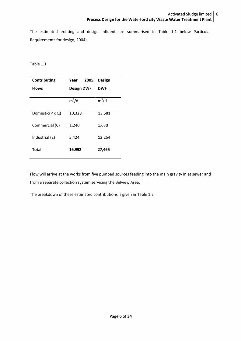
The estimated existing and design influent are summarised in Table 1.1 below Particular
Requirements for design, 2004)
Table 1.1
Contributing
Flows
Year 2005
Design DWF
Design
DWF
m3/d m
3/d
Domestic(P x Q) 10,328 13,581
Commercial (C) 1,240 1,630
Industrial (E) 5,424 12,254
Total 16,992 27,465
Flow will arrive at the works from five pumped sources feeding into the main gravity inlet sewer and
from a separate collection system servicing the Belview Area.
The breakdown of these estimated contributions is given in Table 1.2
8/2/2019 Waterford Tender Design
http://slidepdf.com/reader/full/waterford-tender-design 8/35
Activated Sludge limited
Process Design for the Waterford city Waste Water Treatment Plant
7
Page 7 of 34
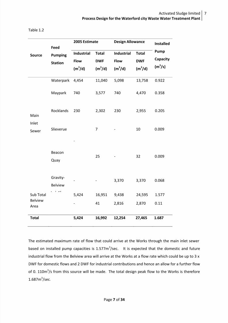
Table 1.2
Source
Feed
PumpingStation
2005 Estimate Design AllowanceInstalled
Pump
Capacity
(m3/s)
Industrial
Flow
(m3/d)
Total
DWF
(m3/d)
Industrial
Flow
(m3/d)
Total
DWF
(m3/d)
Main
Inlet
Sewer
Waterpark 4,454 11,040 5,098 13,758 0.922
Maypark 740 3,577 740 4,470 0.358
Rocklands 230 2,302 230 2,955 0.205
Slieverue 7 - 10 0.009
-
Beacon
Quay25 - 32 0.009
Gravity-
Belview
- - 3,370 3,370 0.068
Sub Total 5,424 16,951 9,438 24,595 1.577
Belview- 41 2,816 2,870 0.11
Area
Total 5,424 16,992 12,254 27,465 1.687
The estimated maximum rate of flow that could arrive at the Works through the main inlet sewer
based on installed pump capacities is 1.577m3/sec. It is expected that the domestic and future
industrial flow from the Belview area will arrive at the Works at a flow rate which could be up to 3 x
DWF for domestic flows and 2 DWF for industrial contributions and hence an allow for a further flow
of 0. 110m3/s from this source will be made. The total design peak flow to the Works is therefore
1.687m3/sec.
8/2/2019 Waterford Tender Design
http://slidepdf.com/reader/full/waterford-tender-design 9/35
Activated Sludge limited
Process Design for the Waterford city Waste Water Treatment Plant
8
Page 8 of 34
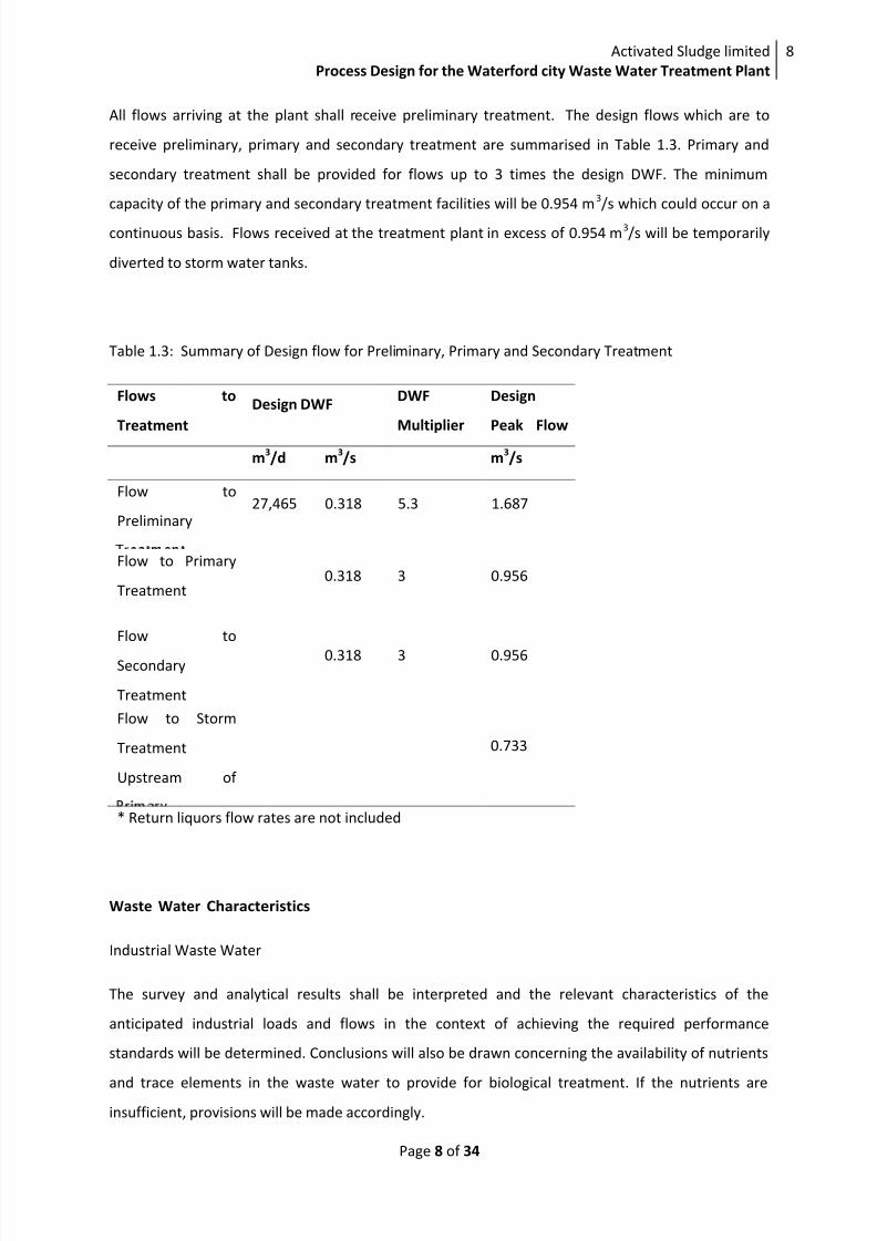
All flows arriving at the plant shall receive preliminary treatment. The design flows which are to
receive preliminary, primary and secondary treatment are summarised in Table 1.3. Primary and
secondary treatment shall be provided for flows up to 3 times the design DWF. The minimum
capacity of the primary and secondary treatment facilities will be 0.954 m3/s which could occur on a
continuous basis. Flows received at the treatment plant in excess of 0.954 m3/s will be temporarily
diverted to storm water tanks.
Table 1.3: Summary of Design flow for Preliminary, Primary and Secondary Treatment
Flows to
Treatment
Design DWFDWF
Multiplier
Design
Peak Flow
m3/d m
3/s m
3/s
Flow to
Preliminary27,465 0.318 5.3 1.687
Flow to Primary
Treatment0.318 3 0.956
Flow to
Secondary
Treatment
0.318 3 0.956
Flow to Storm
Treatment
Upstream of
0.733
* Return liquors flow rates are not included
Waste Water Characteristics
Industrial Waste Water
The survey and analytical results shall be interpreted and the relevant characteristics of the
anticipated industrial loads and flows in the context of achieving the required performance
standards will be determined. Conclusions will also be drawn concerning the availability of nutrients
and trace elements in the waste water to provide for biological treatment. If the nutrients are
insufficient, provisions will be made accordingly.
8/2/2019 Waterford Tender Design
http://slidepdf.com/reader/full/waterford-tender-design 10/35
Activated Sludge limited
Process Design for the Waterford city Waste Water Treatment Plant
9
Page 9 of 34
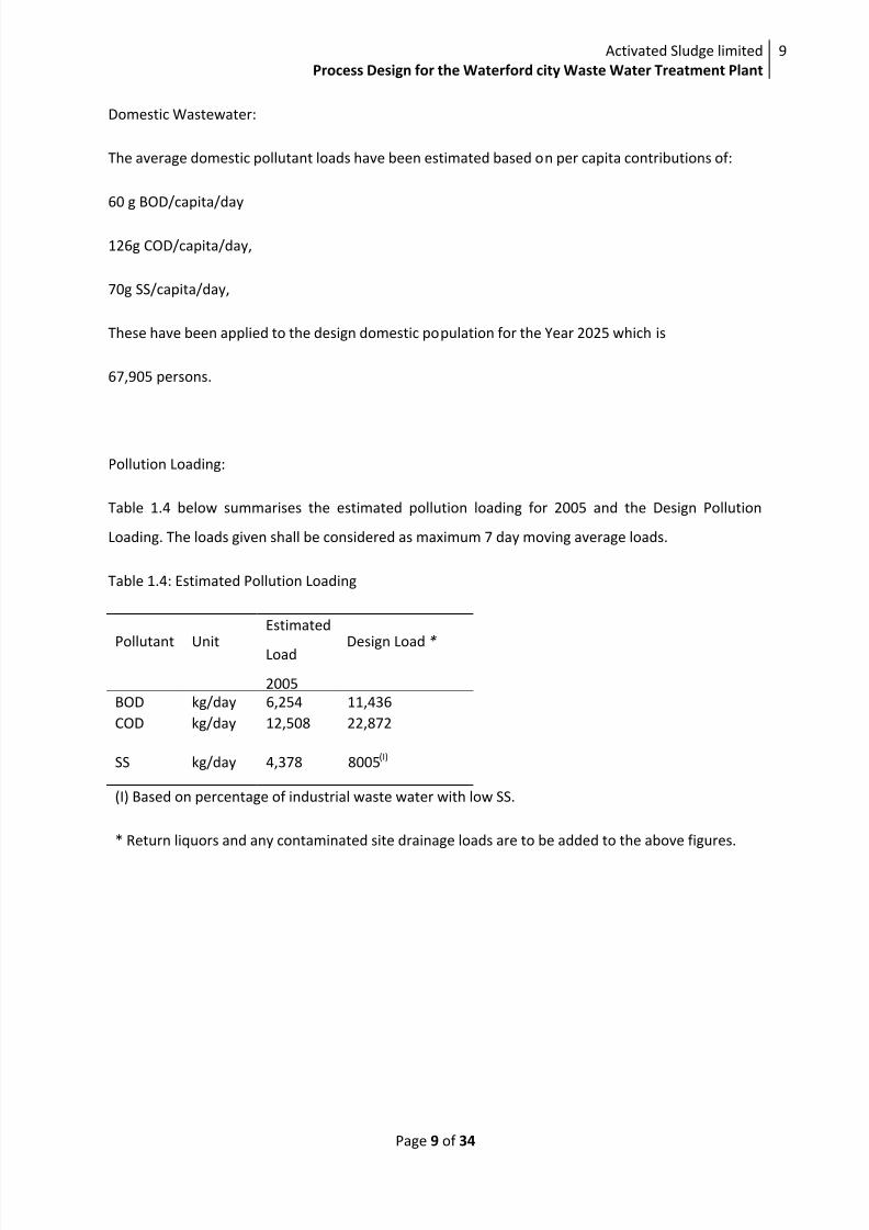
Domestic Wastewater:
The average domestic pollutant loads have been estimated based on per capita contributions of:
60 g BOD/capita/day
126g COD/capita/day,
70g SS/capita/day,
These have been applied to the design domestic population for the Year 2025 which is
67,905 persons.
Pollution Loading:
Table 1.4 below summarises the estimated pollution loading for 2005 and the Design Pollution
Loading. The loads given shall be considered as maximum 7 day moving average loads.
Table 1.4: Estimated Pollution Loading
Pollutant Unit
Estimated
Load
2005
Design Load *
BOD kg/day 6,254 11,436
COD kg/day 12,508 22,872
SS kg/day 4,378 8005(I)
(I) Based on percentage of industrial waste water with low SS.
* Return liquors and any contaminated site drainage loads are to be added to the above figures.

8/2/2019 Waterford Tender Design
http://slidepdf.com/reader/full/waterford-tender-design 11/35
Activated Sludge limited
Process Design for the Waterford city Waste Water Treatment Plant
10
Page 10 of 34
Table 1.5 gives an estimated breakdown of the contribution from the main sectors
contributing to the organic loading to the waste water treatment plant.
Table 1.5
Estimated 2005
Loading(kg BOD/d)
Design Load(kg BOD/d)
Domestic 3098 4,074
Commercial 496 652
Industrial 3060 6,710
Total 6,254 11,436
Variation in loading
The Works shall be capable of treating the design peak flow rate arriving at the plant as given in
Table 1.3 and be capable of treating the Design Load for the various pollutants as given in Table 1.4.
The design shall allow for increases and decreases in the pollutant concentrations within the
catchments and for the variations in infiltration within the collection system.
Modular Expansion
Increased Loadings (+10%, +20%)
The design assumption to be made with respect to influent for the+10% and +20% increases in BOD,
COD and SS load is shown in Table 1.6 below. The loads given shall be considered as maximum 7 day
moving average loads.
Table 1.6
Load
Pollutant Unit +10% Load +20% Load
BOD Kg/day 12,580 13,723
COD Kg/day 25,160 27,446
Ss Kg/day 8,806 9,606

8/2/2019 Waterford Tender Design
http://slidepdf.com/reader/full/waterford-tender-design 12/35
Activated Sludge limited
Process Design for the Waterford city Waste Water Treatment Plant
11
Page 11 of 34
Note I Return liquors and contaminated site drainage flows and loads are to be added to the above
figures.
Note 2 The increased loads could arise from any part of the catchment.
Nutrient Removal
The design influent flow to be assumed for the purposes of expanding the design for nutrient
removal (nitrogen and phosphorus) is given in Table 1.3 and 1.4. The total nitrogen concentration in
waste water shall be assumed to be 40mg/l (all as organic nitrogen and ammonia). The
concentration of phosphorus shall be assumed to be 6mg/litre.
PERFORMANCE STANDARDS
General
The Works shall meet the environmental standards with respect to final effluent quality, sludge
quality as well as satisfying odour and noise requirements. The Works shall meet the Works
performance Guarantees, and the performance standards specified for individual process units
in this tender.
Final Effluent Discharge Standards
The Works shall be capable of producing final effluent meeting the standards specified in
Table 1.7 below.
Table 1.7: Final Effluent Discharge Requirements
Parameter
Standard Compliance Criteria
Target Target
Target A TargetB
A B
BOD, mg/1 25 50 No more than three daily
samples per 60 days with
a value for any one
parameter or all
parameters to be greater
than the standard
No samples with a
value for any one
parameter to be
greater than the
standard
COD, mg/l 125 250
TSS, mg/l 35 87.5
8/2/2019 Waterford Tender Design
http://slidepdf.com/reader/full/waterford-tender-design 13/35
Activated Sludge limited
Process Design for the Waterford city Waste Water Treatment Plant
12
Page 12 of 34
Compliance with the above standards shall be monitored by daily flow proportional sampling.
The above final effluent standard shall apply to the effluent stream from the secondary treatment
plant i.e. excluding storm tanks overflow.
Sludge Quality Standards
The sludge at the time of its use or disposal, shall meet the standards shown in Table 1.8.
Table 1.8: Sludge Quality Requirements (Digestion & Dewatering)
Parameter Standard Compliance
Faecal coliform
concentration 1 000 MPN/gds
Continuously less
than the
Dry solids
concentration23% (w/w)(IJ
Greater than the
standard
Retention time in
pasteurization
Min.2 hoursContinuously
greater than the
Temperature of
sludge during
pasteurization.
Min. 55°CContinuously
greater than
PROCESS DESIGN REQUIREMENTS
Degree of Treatment Required for Particular Flows
The following degree of treatment is required for influent flows:
All flows arriving at the Works shall receive preliminary treatment comprising grit removal andscreening.
Flows up to the design peak flow rate in Table 1.3 shall receive primary treatment and secondary
biological treatment.
Flows in excess of the design peak flow rate for primary and secondary treatment in Table
1.3 shall be diverted as storm water to holding tanks and, shall be returned to the primary
and secondary treatment processes whenever the flow to the Works drops below the

8/2/2019 Waterford Tender Design
http://slidepdf.com/reader/full/waterford-tender-design 14/35
Activated Sludge limited
Process Design for the Waterford city Waste Water Treatment Plant
13
Page 13 of 34
capacity of the primary and secondary treatment stages.
The possibility that the wastewater arriving at the Works may be septic shall be taken into account
and provisions made in the design accordingly.
Preliminary Treatment
Screening
Screening equipment shall be installed within a building. The screens shall have maximum apertures
of 5 mm in either direction. The design velocity through the apertures shall not exceed 1.2 m/s.
Grit Removal
The grit separators shall be capable of removing at least 95% of particles with a specific gravity of
2.65 g/cm3
and with a diameter of 0.2 mm and greater.
Storm Water Treatment
The treatment plant shall include for the storage of storm water in holding tanks with a minimum
capacity of2, 640m3
representing 1 day storage at maximum overflow rate.
Primary Treatment
Primary settlement tanks shall be designed for flows up to the design flow stated in Table
1.3. Tanks shall have a minimum straight wall height of 2.5 m as measured from the top water level
to the top of the base and shall provide a minimum retention period of 1.5 hours at maximum flow
conditions.
The inlet pipe shall discharge within a stilling box or diffusion mechanism located at the centre of the
tank. Where stilling boxes are used these shall occupy a minimum liquid surface area 10% of the
liquid surface area of the tank
Secondary Treatment
Secondary biological treatment shall be provided for flows up to the design flow stated in Table 1.3.
Biological treatment systems shall be designed to achieve a treated effluent standard in accordance
with the requirements stated in Table 1.7.

8/2/2019 Waterford Tender Design
http://slidepdf.com/reader/full/waterford-tender-design 15/35
Activated Sludge limited
Process Design for the Waterford city Waste Water Treatment Plant
14
Page 14 of 34
Activated Sludge Process
Activated sludge systems shall be designed to maximize the settle-ability of the mixed liquor in
downstream clarifiers. Plug flow type systems are the preferred option but consideration will be
given to other systems. Selector tanks should be provided and systems shall be designed to achieve
a Stirred Specific Sludge Volume Index less than 120 ml/g at a mixed liquor suspended solids
concentration of3.5 g/l.
A minimum sludge age of 5 days shall be maintained at a temperature of 100C and the system shall
be designed for a mixed liquor temperature range of 100C - 20
0C.
Dead spots shall be eliminated by providing baffle walls and fillets to corners of tanks where
necessary. A minimum freeboard of 0.75 m shall be provided in all aeration tanks.
Aeration systems shall be capable of maintaining a dissolved oxygen concentration of 2 mg/litre
throughout the full volume of the aeration lank at all times. Suitable arrangements shall be provided
for draining aeration tanks.
Secondary Settlement Tanks
The upward flow method shall be used in the design of the tanks.
The upward flow velocity shall not exceed 0.9 m3/m
2/h with all tanks in operation and 1.2 m
3/m
2/h.
with one tank out of service for maintenance. The minimum hydraulic retention time shall be two
hours and the maximum solids loading rate shall not exceed 75 kg/m2/d.
In all cases the following shall apply:
Settlement tanks shall incorporate rotating bridge scrapers and scum removal systems
Scum removed from the surface of the tanks shall not be returned with the return sludge.
The inlet pipe shall discharge within a stilling box or diffusion mechanism located at the centre of the
tank. Where stilling boxes are used these shall occupy a minimum liquid surface area of 10% of the
liquid surface area of the tank. The Contractor's design shall include for a means of removing scum
from the stilling box.
Sludge return pumps shall be capable of returning flows in the range not narrower than 0.5 to 1.5
times the average inlet flow or within the range 0.3 to 0.7 m3/m
2/h as an underflow rate where the
solids flux design method is adopted.

8/2/2019 Waterford Tender Design
http://slidepdf.com/reader/full/waterford-tender-design 16/35
Activated Sludge limited
Process Design for the Waterford city Waste Water Treatment Plant
15
Page 15 of 34
The side wall depth of the settlement tanks shall not be less than 2.5m
Aeration Systems
Aeration systems shall be designed to maximise oxygen transfer and to react to the changing oxygen
demands in biological treatment systems. Consideration will be given to the separation of aeration
and mixing mechanisms in aeration tanks where appropriate to maximise energy efficiency. Tapered
aeration in plug flow systems shall be provided.
Aeration systems which incorporate blowers shall comprise at least 3 blowers. Blowers shall
be capable of delivering maximum air requirements with the largest single unit out of service.
Duty blowers, diffusers and piping shall be capable of delivering at least 150 per cent of the
air requirements based on the maximum design loading. The maximum air flow in pipework
shall not exceed 15 m/s.
Provision of a system for condensate draining and flushing of the air system will be made.
Pressure tapping shall be provided to monitor pressure drop for each air valve.
Sludge Handling and Treatment
Primary Sludge
Primary sludge from the primary settlement tanks shall be thickened prior to treatment.
Thickening/consolidation tanks shall be designed such that when operating in series with the
sedimentation tanks the thickened sludge shall have a minimum dry solids content of 6%.
Tanks shall be covered and the air extracted for treatment. Tanks shall be designed to provide a
minimum hydraulic retention time of one day at maximum daily sludge flow rates.
Secondary Sludge
Sludge produced in secondary biological treatment processes shall be thickened to a minimum dry
solids content of 5% systems prior to digestion or other sludge treatment processes.
Sludge Storage
Sludge storage facilities shall be provided for Thickened primary sludge and secondary sludge as well
as digested sludge.

8/2/2019 Waterford Tender Design
http://slidepdf.com/reader/full/waterford-tender-design 17/35
Activated Sludge limited
Process Design for the Waterford city Waste Water Treatment Plant
16
Page 16 of 34
Separate tanks for storage for 3 days production of thickened
primary and secondary sludge at maximum design loading will be provided in addition to a minimum
of 5 days storage capacity for digested sludge. All sludge storage facilities shall be covered and the
headspace will be extracted to the odour treatment plant.
Sludge Blending
Thickened primary and secondary biological sludge shall be combined and mixed in the sludge
blending/buffer tank from where the sludge shall be pumped to the sludge treatment processes.
Sludge Pasteurisation
Sludge pasteurization will be designed to meet the standards required for disposal of sludge to
agriculture. The system shall be designed to handle peak flows generated by the treatment plant.
Sludge Digestion
The sludge retention time shall be a minimum of 14 days. The digesters shall be equipped with an
automatic temperature control systems. In each digester, at least two temperature sensors shall be
installed. External heat exchangers shall be utilised.
The average daily temperature of the sludge in the digester(s) shall not be outside the range of 35±0.5°C. The instantaneous temperature shall be continuously in the range 35±2°C. The biogas
generated during digestion shall be directed to the gas holder. An enclosed flare stack shall also be
provided. All necessary safety devices shall be provided.
Sludge Dewatering
Mechanical thickening and dewatering plants, and associated pumps shall be arranged in at
least one duty stream and at least one additional stream of the same size as the duty stream.
The duty stream(s) shall be sized to handle at least the average daily sludge quantities over
not more than 20 hours per day. The additional stream shall be used to treat the peak loads
and serve as a standby during average loading.
Polyelectrolyte solution preparation and dosing systems shall be provided for all mechanical
devices used for sludge thickening and dewatering. Duty and standby dosing units shall be

8/2/2019 Waterford Tender Design
http://slidepdf.com/reader/full/waterford-tender-design 18/35
Activated Sludge limited
Process Design for the Waterford city Waste Water Treatment Plant
17
Page 17 of 34
provided.
The minimum dry solids content following dewatering shall be 23%.
Dewatering systems shall be fully enclosed and located in a sludge dewatering building.
Solids Disposal
The disposal of all screenings, grit and sludge generated shall be carried out in accordance with the
requirements of the Waste Management Act 1996 and Implementary Regulations and in accordance
with any permits or licences obtained.

8/2/2019 Waterford Tender Design
http://slidepdf.com/reader/full/waterford-tender-design 19/35
Activated Sludge limited
Process Design for the Waterford city Waste Water Treatment Plant
18
Page 18 of 34
PRELIMINARY TREATMENT
INLET WORKS
Approach Channels
The approach channels are designed to receive flows up to 5.3DWF from the incoming sewer as
requested by the tender document. A flow velocity range of 0.45 to 0.9m/s is chosen to prevent
both solids settlement at lower velocities and damage to screens at higher velocities (Horan, 2011a).
Screen specification with apertures of 3mm and matching the designed flow channel is obtained
from Degremond technologies online.
The design calculations for the approach channels are based on an adaptation of the formula A
5.3DWF = 27465M3/d = 1.687m3
/s (see table 1.3)
DWF = 0.318m3/s
At DWF,
Area =
= 0.707m2
At 5.3DWF,
Area = = 1.874m
2
Number of channels required = 2.651
This implies two channels will not be enough and three channels are therefore designed. The total
area of the three channels is
Flow Velocity = =
= 0.9m/s
To maintain flow velocity above 0.45,
= 0.471
The width required for the screen is given buy
= 1.052m

8/2/2019 Waterford Tender Design
http://slidepdf.com/reader/full/waterford-tender-design 20/35
Activated Sludge limited
Process Design for the Waterford city Waste Water Treatment Plant
19
Page 19 of 34
Taking a depth to width ratio of 1.15, and let the width be 1m,
Depth = 1.15 x 1. 052m = 1.21m
Screens
Screen specification that fit the design of the channels is obtained from manufacturers. An inficro
screen (Degremond Technologies, 2011) climber screen with apertures of 3m will be installed. Such
a micro screen has the capacity to remove 95% of debris in the waste water
Grit removal
A hydrodynamic grit removal system will be installed. This is preferred because it is relatively
compact and maintains very high removal efficiencies over a wide range of flows (idswater, 2011).
This type of screen is highly efficient in separation, reduces odours, has low wear rate and can
remove all grit 0.1mm (140 mesh) and larger.
Storm Tanks Design
The storm tanks are designed to retain an excess of flow to full treatment of 2.3DWF (tender
requirement). Two tanks in series are designed with the first one receiving the first flush. The surface
loading is 10m/h, height to breadth ratio is greater than 2 and retention time is 2hrs (Horan, 2011b)
The designed volume of the storm tank is
V= Q x HRT = 2.3 DWF x 2/24 = 63169.5m3/d x 2/24d = 5263.2m
3
Tank area =
=(
)= 263.2m
2
As stated above, two tanks in series are used in the design, thus, the actual volume of each tank is
2631.6m3.
Taking L: W = 3.04, W = 6.58m, L= 3.04 x 6.58 = 20m
Tank depth =
=
= 10m

8/2/2019 Waterford Tender Design
http://slidepdf.com/reader/full/waterford-tender-design 21/35
Activated Sludge limited
Process Design for the Waterford city Waste Water Treatment Plant
20
Page 20 of 34
Fig 1: layout of the preliminary treatment works.
PRIMARY TREATMENTThe primary treatment tanks designed are of the radial type. They are preferred because their
efficient scraping mechanism and equal flow divisions (Horan, 2011c). The tanks are designed for
BOD and TSS removal of 30% and 60% respectively.
The tanks are designed such that the influent is discharged towards the centre of the surface area. A
stilling basin which is 10% of the tank surface area in size is used to dissipate the velocity or energy
of the influent. The treated effluent flows over a v-notch weir while the settled sludge is withdrawn
from the tank bottom through a pipe.
Tank shell design
Design data
Surface loading rate at FFT = 90m3/m
2.d (Horan, 2011d)
HRT= 1.5 hrs. (Tender document)
Maximum allowable weir overflow rate = 450m3/m
2.d (ibid)
Flow to primary tank = 3DWF = 82395m3/d
Tank surface area=
= = 916m
2
Tank Volume = = 1.5d/24 82395m3/d = 5150m3
Inlet works
Storm Tanks
Formula “A”
weirInlet
sewer
Water course
> 6DWF
>3DWF
FFT Primary
sedimentation
tank
8/2/2019 Waterford Tender Design
http://slidepdf.com/reader/full/waterford-tender-design 22/35
Activated Sludge limited
Process Design for the Waterford city Waste Water Treatment Plant
21
Page 21 of 34
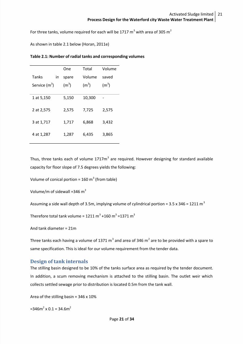
For three tanks, volume required for each will be 1717 m3
with area of 305 m2
As shown in table 2.1 below (Horan, 2011e)
Table 2.1: Number of radial tanks and corresponding volumes
Tanks in
Service (m3)
One
spare
(m3)
Total
Volume
(m3)
Volume
saved
(m3)
1 at 5,150 5,150 10,300 -
2 at 2,575 2,575 7,725 2,575
3 at 1,717 1,717 6,868 3,432
4 at 1,287 1,287 6,435 3,865
Thus, three tanks each of volume 1717m3
are required. However designing for standard available
capacity for floor slope of 7.5 degrees yields the following:
Volume of conical portion = 160 m
3
(from table)
Volume/m of sidewall =346 m3
Assuming a side wall depth of 3.5m, implying volume of cylindrical portion = 3.5 x 346 = 1211 m3
Therefore total tank volume = 1211 m3
+160 m3
=1371 m3
And tank diameter = 21m
Three tanks each having a volume of 1371 m3
and area of 346 m2
are to be provided with a spare to
same specification. This is ideal for our volume requirement from the tender data.
Design of tank internals
The stilling basin designed to be 10% of the tanks surface area as required by the tender document.
In addition, a scum removing mechanism is attached to the stilling basin. The outlet weir which
collects settled sewage prior to distribution is located 0.5m from the tank wall.
Area of the stilling basin = 346 x 10%
=346m2
x 0.1 = 34.6m2

8/2/2019 Waterford Tender Design
http://slidepdf.com/reader/full/waterford-tender-design 23/35
Activated Sludge limited
Process Design for the Waterford city Waste Water Treatment Plant
22
Page 22 of 34
Outlet weir length for the three tanks = 3π (21-1) m = 188.5m
The weir loading rate =
=
= 437.2m3/m
2.d
Surface loading is high and should be reduced by providing a cantilevered double sided weir.
However, this is still within the recommended weir loading rate of 100 to 450m3/m
2.d (Horan,
2011c).
Figure 2: A simple line diagram of the primary sedimentation tank (adapted from Horan, 2011d). The
secondary sedimentation tank has a similar design but without the scum removal mechanism
THE ACTIVATED SLUDGE PROCESS DESIGNThe activated sludge process basically involves the oxidation of organic matter (as BOD) by bacteria
in the presence of oxygen. The end products are largely new bacterial cells, carbon dioxide as well as
relatively smaller quantities of nitrogen and phosphorus compounds.
Once the bacteria multiply in huge quantities, the settle to form a floc called the activated sludge.
For a brand new treatment plant, the reactor has to be seeded with bacteria from external sources
and allowed to grow for a few weeks to a few months. For existing plants, the recycle flow from the
secondary tanks return some active sludge to seed the influent coming from the primary tank into
the reactor. Manual or mechanized systems keep the reactor chamber supplied with air; allowing
bacteria to breakdown the organic matter. A good balance between the substrate in the wastewater
6
2
7
8
5
1
2
3
1- Inflow 2- Stilling basin 3- Scum removal 4- Scraper
5- Sludge withdrawal 6- Scraper drive (fixed bridge mounted)
7- Peripheral overflow weir 8- Flow slope
8/2/2019 Waterford Tender Design
http://slidepdf.com/reader/full/waterford-tender-design 24/35
Activated Sludge limited
Process Design for the Waterford city Waste Water Treatment Plant
23
Page 23 of 34
and the microorganism must be maintained for proper working of the system. A certain amount of
the microorganisms must be wasted to achieve this (Lin, 2001)
Design calculations
The primary settlement tanks remove 30% and 60% BOD and TSS respectively. Thus, the BOD and
TSS load to the aeration tanks are:
BOD load = 11436 Kg/d x 70% = 8005.2Kg/d
TSS load = 8005Kg/d x 40% = 3202Kg/d
Therefore,
TSS: BOD = 3202Kg/d: 8005.2Kg/d = 0.4
Population equivalent PE = =
= 111,833
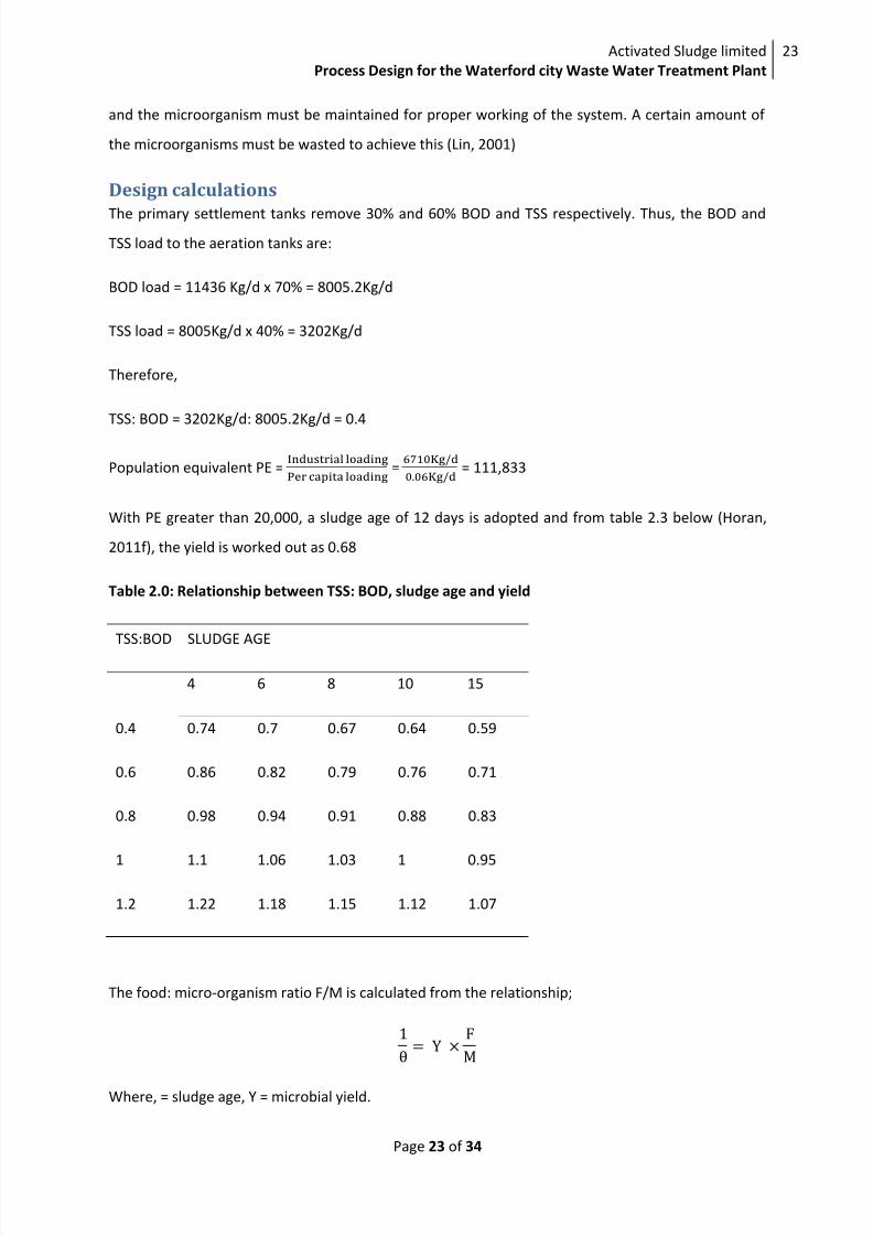
With PE greater than 20,000, a sludge age of 12 days is adopted and from table 2.3 below (Horan,
2011f), the yield is worked out as 0.68
Table 2.0: Relationship between TSS: BOD, sludge age and yield
TSS:BOD SLUDGE AGE
4 6 8 10 15
0.4 0.74 0.7 0.67 0.64 0.59
0.6 0.86 0.82 0.79 0.76 0.71
0.8 0.98 0.94 0.91 0.88 0.83
1 1.1 1.06 1.03 1 0.95
1.2 1.22 1.18 1.15 1.12 1.07
The food: micro-organism ratio F/M is calculated from the relationship;
Where, = sludge age, Y = microbial yield.
8/2/2019 Waterford Tender Design
http://slidepdf.com/reader/full/waterford-tender-design 25/35
Activated Sludge limited
Process Design for the Waterford city Waste Water Treatment Plant
24
Page 24 of 34
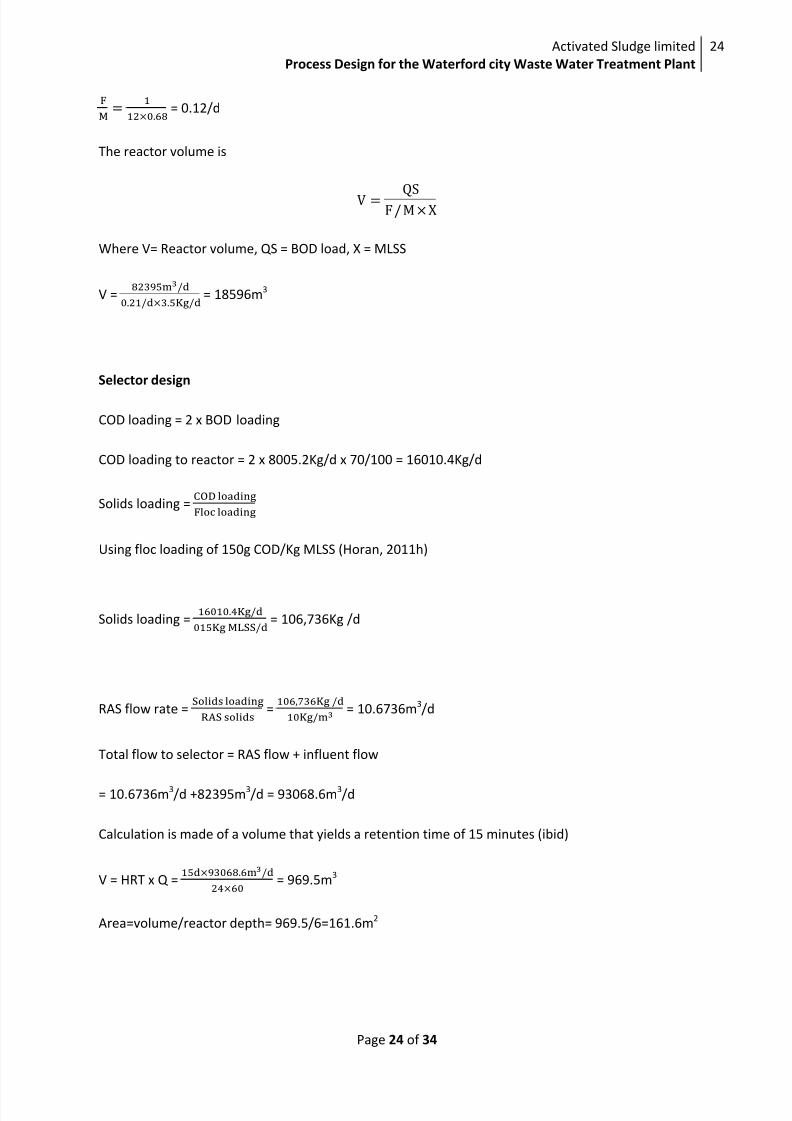
= 0.12/d
The reactor volume is
Where V= Reactor volume, QS = BOD load, X = MLSS
V =
= 18596m3
Selector design
COD loading = 2 x BOD loading
COD loading to reactor = 2 x 8005.2Kg/d x 70/100 = 16010.4Kg/d
Solids loading =
Using floc loading of 150g COD/Kg MLSS (Horan, 2011h)
Solids loading =
= 106,736Kg /d
RAS flow rate =
= = 10.6736m
3/d
Total flow to selector = RAS flow + influent flow
= 10.6736m3/d +82395m3/d = 93068.6m3/d
Calculation is made of a volume that yields a retention time of 15 minutes (ibid)
V = HRT x Q =
= 969.5m3
Area=volume/reactor depth= 969.5/6=161.6m2
8/2/2019 Waterford Tender Design
http://slidepdf.com/reader/full/waterford-tender-design 26/35

8/2/2019 Waterford Tender Design
http://slidepdf.com/reader/full/waterford-tender-design 27/35
Activated Sludge limited
Process Design for the Waterford city Waste Water Treatment Plant
26
Page 26 of 34
SOTR = N0=
Where
N0 = Oxygen transfer into clean water (Kg/d)
N = Oxygen transfer into sewage (Kg/d)
Cs = Saturated oxygen concentration
α = Correction factor for the effect of waste water on KLa
β = Correction factor for the effect of waste water on Cs
TABLE 3.0: Aeration pockets
Height (m) 6 6 6 6 6
c (mg/L) 0.2 1 1.5 2 2.5
T (oc) 20 20 20 20 20
α 0.4 0.5 0.7 0.8 0.9
β 0.85 0.85 0.85 0.85 0.85
OTR (kg/d) 3152 788 525 525 263
SOTR(kg/d) 9460 2060 1038 965 458
Diffuser (nr) 438 95 48 45 21
Diffuser performance = 0.15Kg O2/diffuser
Number of diffusers = SOTR/Diffuser performance

8/2/2019 Waterford Tender Design
http://slidepdf.com/reader/full/waterford-tender-design 28/35
Activated Sludge limited
Process Design for the Waterford city Waste Water Treatment Plant
27
Page 27 of 34
SECONDARY TREATMENT TANKSThe secondary tanks are designed according to the tender requirement include making provision for
flows up to the design flow rate and using modular construction for ease of expansion. Structurally,
secondary sedimentation tanks are constructed the same way as primary tanks. They are however
designed to have larger areas to cope with the huge amount of BOD and TSS removal needed.
The sewage from aeration chamber flows into the secondary sedimentation tank and remains there
for 2hrs. During this period, the sludge settles and thickens into various zones at the bottom of the
tank. Part of the thickened sludge is returned to the activated sludge plant to seed the incoming flow
from the primary thank with bacteria. The balance of the thickened sludge corresponding to the
microbial growth is withdrawn and sent to the anaerobic digestion plant for further processing.
Liquid effluents from the secondary thanks typically have nearly all their BOD removed in the tank.
They are tested to ensure they have met consent standards before being discharged to the
environment.
Tank design calculations
The tank area is given by
Where: A = tank area
SSVI = sludge specific volume index = 3500ml/g
Q u = underflow rate = 1144.3m3/h
Q s =3DWF = 3433.1m3/h
Inserting values in the above equation gives
A = 7563.8m2
The total flow rate to the tank is
Q s + Q u = 3433.1m3/h + 1144.3m
3/h = 4577.4 m
3/h
8/2/2019 Waterford Tender Design
http://slidepdf.com/reader/full/waterford-tender-design 29/35
Activated Sludge limited
Process Design for the Waterford city Waste Water Treatment Plant
28
Page 28 of 34
Surface loading = =
= 0.61m
3/m
2h
Tank volume = Q x HRT = 4577.5m3/h x 2hrs = 9155m
3
Three tanks in service are designed with one spare. Thus the respective volume and area of each
tank are
Volume of each tank = 9155m3/3 = 3051.3m
3
Area of each tank = 7563.8 m2/3 = 2521.3m
2
Other calculations of tank parameters shown below were done using standard tables (Horan,
2011d). A floor slope of 100
and sidewall depth of 3.4 meters were used.
Tank diameter = 30m
Conical section = 653m3
Circular portion = 3.4m x 707m3
=3056.8m3
Design of tank internals
Stilling basin is designed with an area equal to 10% 0f tank surface area (tender requirement).
Stilling basin for each tank = 2521.3m2
x 10/100 = 252.13m2
Outlet weir is 0.5m from the circumference of the tank. Therefore,
Weir length = 3(D-1) πm = 3 x 9 x π = 73.3m
Weir overflow rate =
= 401.9m2/d
This is between the generally recommended range of 100-450m2/d (Horan, 2011). It is however still
high and will be reduced using a double-sided weir.
SLUDGE ARISINGS
The primary tanks removed 60% TSS equivalent to 4803Kg/d at 1.5% solids (i.e. 15Kg/m3).
Amount of sludge removed = 0.6 x 8005 = 4803Kg/d
8/2/2019 Waterford Tender Design
http://slidepdf.com/reader/full/waterford-tender-design 30/35
Activated Sludge limited
Process Design for the Waterford city Waste Water Treatment Plant
29
Page 29 of 34
Volume of sludge removed = = 320.2m
3/d
The amount of sludge produced by the secondary tank is = Yield x BOD load
= 0.68 x 8005.2Kg/d
= 5443.3Kg/d
SSVI = 120ml/g. This implies 1Kg of the sludge will occupy 0.12m3
of volume. Therefore;
Volume of sludge produced = 0.12m3/Kg x 5443.3Kg/d = 653.2 m
3/d
Total daily sludge production = 320.2m3
/d +
653.2 m3
/d
=
973.4m3
/d
Sludge storage prior to digestion
A minimum of three days storage capacity for both primary and secondary thickened sludge based
on maximum design loading capacity is provided.
For the primary thickened sludge, storage volume = flow x HRT
320.2m3/d x 3d = 960.6m
3
Storage capacity provided = 1000m3
For the secondary thickened sludge, storage volume = 653.2 m3/d x 3d = 1959.6 m
3
Storage capacity provided = 2000m3
Sludge thickening and dewatering
Primary and secondary sludge are thickened separately. The centrifuge thickening system is used
because it is highly efficient at managing large quantities of sludge and dewaters the digested from
the anaerobic digestion process. Centrifugal thickeners are also amenable to modular
construction(Europy, 2011)
Primary sludges are thickened to a dry solids content of 6% with a VSS concentration of 75% while
secondary sludge are thickened to a dry solids content of 6% with a VSS concentration of 80%.

8/2/2019 Waterford Tender Design
http://slidepdf.com/reader/full/waterford-tender-design 31/35
Activated Sludge limited
Process Design for the Waterford city Waste Water Treatment Plant
30
Page 30 of 34
MESOPHILIC ANAEROBIC DIGESTIONAnaerobic digestion involves complex biochemical processes in which micro-organisms breakdown
organic matter in the absence of air. Anaerobic digestion that takes place at 35-370C is called
mesophilic anaerobic digestion (Vindis, 2009).
Design of the anaerobic digester
The sludge flow to the digester is = 973.4m3/d
Average flow to digester = 1.3 x 973.4m3/d = 1265.42 m
3/d
The retention time is 14 days (tender document)
Digester volume = Flow x HRT = 1265.42m3/d x 14d = 17715.88m
3
Taking a side depth of 9m (with 0.5m additional as free board)
Tank area = 17716m3/ 9m
=1968.4m
2
The design provides for two digesters each of volume 17716m3/
/2 = 8858m3
Gas Generation
The primary tank generates:
TSS = 320.2m3/d x 60Kg/m
3= 19212Kg/d
VSS = 19212Kg/d x 75/100 = 14409Kg/d
Ash = 19212Kg/d - 14409Kg/d = 4803Kg/d
The secondary tank generates:
TSS = 653.2m3/d x 60Kg/m
3= 39192Kg/d
VSS = 39192Kg/d x 80/100 = 31353.6Kg/d
Ash = 7838 Kg/d
Combined TSS = 39192Kg/d + 19212Kg/d = 58404Kg/d

8/2/2019 Waterford Tender Design
http://slidepdf.com/reader/full/waterford-tender-design 32/35
Activated Sludge limited
Process Design for the Waterford city Waste Water Treatment Plant
31
Page 31 of 34
Combined VSS = 31353.6Kg/d + 14409Kg/d = 45762.6Kg/d
Combined ash = 7838.7Kg/d + 4803Kg/d = 12667.4Kg/d
48% of the VSS is destroyed in the digester.
VSS Destroyed = 45762.6Kg/d x 48/100 = 21966Kg/d
Gas yield
1kg of VSS destroyed yields 0.45m3
of methane. Total volume of methane produced is therefore
VSS destroyed x 0.45m3
= 21966 x 0.45m3
= 9884.7m3
Gas storage
Two inflatable membranes gas storage shall be provided having volumes of 5000m3.
CHP Power output
1Nm3
of methane yields 9.97kWh (Horan, Nigel, 20). Energy produced daily is therefore:
9.97kWh/1Nm3
x 9884.7m3
= 98550.5kWh
Power =
Dewatering
The digestate is thickened to a minimum of 23% dry solid as the tender requires. The sludge
thickening centrifuge is used for the dewatering process thus keeping operational cost low.
8/2/2019 Waterford Tender Design
http://slidepdf.com/reader/full/waterford-tender-design 33/35
Activated Sludge limited
Process Design for the Waterford city Waste Water Treatment Plant
32
Page 32 of 34
Nutrient recovery
The digestate from the MAD process is very rich in nutrients especially nitrogen and phosphorus.
They can be applied directly to agricultural lands within the limit of local regulations. The digested
liquor is also rich enough to precipitate a magnesium ammonium phosphate called struvite
(Mg.NH4.6H2O). Struvite has been found to be a good slow-release fertilizer and in the face of global
phosphorus shortage (Horan Nigel 22), struvite production will contribute to the economy of the
waste water plant operations.
The Ostara pearl® process (Horan Nigel 22) of manufacturing struvite from digestate liquor is built
into this design as part of future expansion plans. Up to 90% phosphorus and 40% ammonia load can
be removed from the digestate liquor using this method (Ostara technologies).

8/2/2019 Waterford Tender Design
http://slidepdf.com/reader/full/waterford-tender-design 34/35
Activated Sludge limited
Process Design for the Waterford city Waste Water Treatment Plant
33
Page 33 of 34
CONCLUSION
Units operations Flow (m3 /d) BOD (kg/d) TSS (kg/d)
1. Screen 145564.5 11,436 8005
2. water course >145564.5 11,436 8005
3. Grit chamber 145564.5 11,436 8005
4. Primary Sedimentation tank 82,395 8005.2 3202
5. Storm tank >63169.5
6. Returned Activated Sludge 27,465
7. Secondary sedimentation tank 82395 988.7 1400.78. Sludge thickener 973.4
9. Blender/storage 973.4
10. Digester 973.4
11. Digestate store 973.4
12. Belt filter press
13. Biogas Storage
14. CHP
14
5
67
9 8
10
11
14
1213
2
3

8/2/2019 Waterford Tender Design
http://slidepdf.com/reader/full/waterford-tender-design 35/35
Activated Sludge limited
Process Design for the Waterford city Waste Water Treatment Plant
34
REFERENCESHoran N. (2011) Approach channels and screens (CIVE 5532 Lecture note), school of civil engineering,
University of Leeds.
Degremond Technologies. (2011). Infilco climber screen. Available at www.degremont-
technologies.com/IMG/pdf/CLIMBER_SCREEN_US_Infilco.pdf (accessed on 12/1/12)
Idswater. (2011). PISTA Grit Removal System. Available at
http://www.idswater.com/water/us/grit_removal/1037/products.html (accessed on
12/1/12)
Horan N. (2011) Dealing with drainage (CIVE 5532 Lecture note), school of civil engineering,
University of Leeds.
Horan N. (2011) Grit Removal (CIVE 5532 Lecture note), school of civil engineering, University of
Leeds.
Horan N. (2011) Design of radial flow tanks (CIVE 5532 Lecture note), school of civil engineering,
University of Leeds.
Horan N. (2011) Primary Sedimentation Tanks (CIVE 5532 Lecture note), school of civil engineering,
University of Leeds.
Lin, S (2001) Water and Wastewater Calculation Manual , London, Mc Graw-Hill.
Horan N. (2011) Estimating Reactor Volumes (CIVE 5532 Lecture note), school of civil engineering,
University of Leeds.
Horan N. (2011) Selectors and Anoxic Zones (CIVE 5532 Lecture note), school of civil engineering,
University of Leeds.
Horan N. (2011) Reactor Aspect Ratio (CIVE 5532 Lecture note), school of civil engineering,
University of Leeds.
Euroby. (2011). Centrifugal Thickening. Available at
http://www.euroby.com/cent_thickening.htm?gclid=CIHy2PGd860CFUoifAodjRZ9sA (accessed on
16/1/2012)
Vindis et al. (2011). The impact of anaerobic digestion on biogas production. Available at
http://www.journalamme.org/papers vol36 2/36210.pdf (accessed on 20/1/2012)