Embed Size (px)
Citation preview
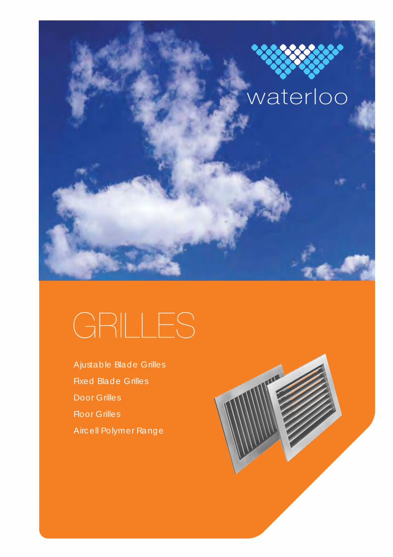
GRILLESAjustable Blade Grilles
Fixed Blade Grilles
Door Grilles
Floor Grilles
Aircell Polymer Range
Adjustable Blade Grilles1H,1V, 2H, 2V Single and Double Deflection Grilles . . . . . . . . . . . . . .. . . . . . . . . . . . . . . . . . . . . . . . . . . . . . . . . . . . . . .41RV, 2RV Adjustable Duct Grilles . . . . . . . . . . . . . . . . . . . . . . . . . . . . . . . . . . . . . . . . . . . . . . . . . . . . . . . . . . . . . . . . . . . . . .6(R)RTC, 2(R)RTC Reversible Core Grilles . . . . . . . . . . . . . . . . . . . . . . . . . . . . . . . . . . . . . . . . . . . . . . . . . . . . . . . . . . . . . .8
Fixed Blade Grilles3HG, 3HJ, 3HF, GC5, PER Exhaust Grilles . . . . . . . . . . . . . . . . . . . . . . . .. . . . . . . . . . . . . . . . . . . . . . . . . . . . . . . . . . . . . .14ALN, ALM, ALF, ALG, ALJ Airline Linear Grille . . . . . . . . . . . . . . . . . . . . . . . . . . . . . . . . . . . . . . . . . . . . . . . . . . . . . . . .16SG1, SG2, SG3 Security Grilles . . . . . . . . . . . . . . . . . . . . . . . . . . . . . . . . . . . . . . . . . . . . . . . . . . . . . . . . . . . . . . . . . . . . . .20
Door / Sidewall GrillesNS, DV, NSNL Air Transfer Grilles . . . . . . . . . . . . . . . . . . . . . . . . . . . . . . . . . . . . . . . . . . . . . . . . . . . .. . . . . . . . . . . . . . . .22WFV,WFVG Fire Rated Transfer Grilles . . . . . . . . . . . . . . . . . . . . . . . . . . . . . . . . . . . . . . . . . . . . . . . . . . . . . . . . . . . . .24DSRX Acoustic Transfer Grilles . . . . . . . . . . . . . . . . . . . . . . . . . . . . . . . . . . . . . . . . . . . . . .. . . . . . . . . . . . . . . . . . . . . . . . .26WPT Sidewall Grilles . . . . . . . . . . . . . . . . . . . . . . . . . . . . . . . . . . . . . . . . . . . . . . . . . . . . . . . . . . . . . . . . . . . . . . . . . . . . . . . .28
Floor GrillesAFG Light Duty Floor Grilles . . . . . . . . . . . . . . . . . . . . . . . . . . . . . . . . . . . . . . . . . . . . . . . . . . . . . . . . . . . . . . . . . . . . . . . .30HDFG Heavy Duty Floor Grilles . . . . . . . . . . . . . . . . . . . . . . . . . . . . . . . . . . . . . . . . . . . . . . . . . . . . . . . . . . . . . . . . . . . .32
Aircell Polymer GrillesAircell S, D, G, A, T, E Aircell Polymer Grilles . . . . . . . . . . . . . . . . . . . . . . . . . . . . . . . . . . . . . . . . . . . . . . . . . . . . . . . . .36Aircell N Neck Reducers . . . . . . . . . . . . . . . . . . . . . . . . . . . . . . . . . . . . . . . . . . . . . . . . . . . . . . . . . . . . .. . . . . . . . . . . . . . .39Aircell GO Opposed Blade Dampers . . . . . . . . . . . . . . . . . . . . . . . . . . . . . . . . . . . . . . . . . . . . . . . . . . . . . . . . . . . . . . . .39OBSS Aluminium Opposed Blade Damper for E600 . . . . . . . . . . . . . . . . . . . . . . . . . . . . . . . . . . . . . . . . . . . . . . . . . .39
Technical InformationPBG Grille Plenum Chambers . . . . . . . . . . . . . . . . . . . . . . . . . . . . . . . . . . . . . . . . . . . . . . . . . . . . . . . . . . . . . . . . . . . . . . .40FDC, FDQ, OBCO, OBSS Plenum Control Options . . . . . . . . . . . . . . . . . . . . . . . . . . . . . . . . . . . . . . . . . . . . . . . . . . .40Fixing Options Various . . . . . . . . . . . . . . . . . . . . . . . . . . . . . . . . . . . . . . . . . . . . . . . . . . . . . . . . . . . . . . . . . . . . . . . . . . . .41R16, R25, R32 Border Options . . . . . . . . . . . . . . . . . . . . . . . . . . . . . . . . . . . . . . . . . . . . . . . . . . . . . . . . . . . . . . . . . . . . . .41RC, AF, PF Sub Frame Options . . . . . . . . . . . . . . . . . . . . . . . . . . . . . . . . . . . . . . . . . . . . . . . . . . . . . . . . . . . . . . . . . . . . . .41OBSS, ED Volume Dampers . . . . . . . . . . . . . . . . . . . . . . . . . . . . . . . . . . . . . . . . . . . . . . . . . . . . . . . . . . . . . . . . . . . . . . . .42DT-2M Air Turn Volume Regulator . . . . . . . . . . . . . . . . . . . . . . . . . . . . . . . . . . . . . . . . . . . . . . . . . . . . . . . . . . . . . . . . . . . . .42Technical Information . . . . . . . . . . . . . . . . . . . . . . . . . . . . . . . . . . . . . . . . . . . . . . . . . . . . . . . . . . . . . . . .. . . . . . . . . .43
Contents
30.1oolretaW
Adjustable Blade Grilles1H 1V 2H 2V
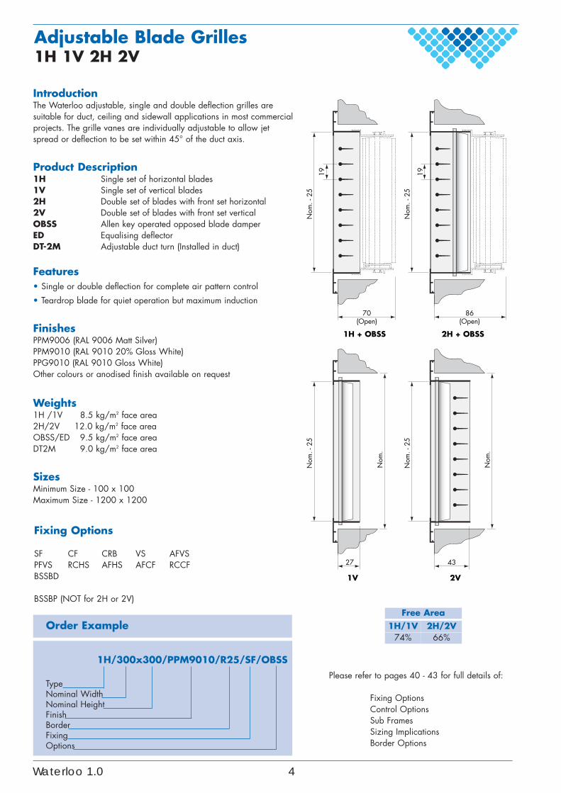
IntroductionThe Waterloo adjustable, single and double deflection grilles aresuitable for duct, ceiling and sidewall applications in most commercialprojects. The grille vanes are individually adjustable to allow jetspread or deflection to be set within 45° of the duct axis.
Product Description1H Single set of horizontal blades1V Single set of vertical blades2H Double set of blades with front set horizontal2V Double set of blades with front set verticalOBSS Allen key operated opposed blade damperED Equalising deflectorDT-2M Adjustable duct turn (Installed in duct)
Features• Single or double deflection for complete air pattern control
• Teardrop blade for quiet operation but maximum induction
FinishesPPM9006 (RAL 9006 Matt Silver)PPM9010 (RAL 9010 20% Gloss White)PPG9010 (RAL 9010 Gloss White)Other colours or anodised finish available on request
Weights1H /1V 8.5 kg/m2 face area2H/2V 12.0 kg/m2 face areaOBSS/ED 9.5 kg/m2 face areaDT2M 9.0 kg/m2 face area
SizesMinimum Size - 100 x 100Maximum Size - 1200 x 1200
Order Example
1H/300x300/PPM9010/R25/SF/OBSS
TypeNominal WidthNominal HeightFinishBorderFixingOptions
Fixing Options
SF CF CRB VS AFVSPFVS RCHS AFHS AFCF RCCFBSSBD
BSSBP (NOT for 2H or 2V)
Please refer to pages 40 - 43 for full details of:
Fixing OptionsControl OptionsSub FramesSizing ImplicationsBorder Options
Free Area1H/1V 2H/2V
74% 66%
70(Open)
Nom
. - 2
5
1986
(Open)
Nom
. - 2
5
27
Nom
.
Nom
. - 2
5
43
Nom
.
Nom
. - 2
5
1V 2V
19
1H + OBSS 2H + OBSS
Waterloo 1.0 4
5000
4000
3000
2000
1000900
800
700
600
500
400
300
200
10090
80
70
60
50
25
50
104540
30
20
20
10
5
1
8
65
4
3
2
1
403020
10
543
2
1
50
40
30
20
10
89
76
5
4
3
2
3
4
5
678910
20
AIR FLOWRATE(l/s)
Throw (m)(Vt = 0.4 m/s)
NCLevel
Static PressurePs (Pa)
NOMINALHEIGHT
(mm)
NOMINALWIDTH(mm)
PivotLine
0˚ D
efle
ctio
n
45˚
Def
lect
ion
0˚ D
efle
ctio
n
45˚
Def
lect
ion
0˚ D
efle
ctio
n
0˚ D
efle
ctio
n
45˚
Def
lect
ion
150
100
150
200
300
400
500
600
800
700
1000
1200
200
300
400
500
600
700
800
1000
1200
PIV
OT
LIN
E
45
40
30
20
Velocity(m/s) ongrille face
throw
600mmmax
Nomogram based on ceiling effect jet as shown. For free jet correction factor see notes above.
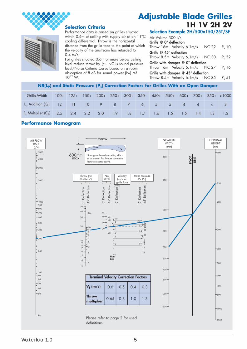
NR(Lp) and Static Pressure (Ps) Correction Factors for Grilles With an Open Damper
Grille Width 100+ 125+ 150+ 200+ 250+ 300+ 350+ 450+ 550+ 600+ 700+ 850+ >1000
Lp Addition (CL) 12 11 10 9 8 7 6 5 5 4 4 4 3
Ps Multiplier (CP) 2.5 2.4 2.2 2.0 1.9 1.8 1.7 1.6 1.5 1.5 1.4 1.3 1.2
Selection Example 2H/500x150/25T/SFAir Volume 300 I/sGrille @ 0° deflectionThrow 16m Velocity 6.1m/s NC 22 Ps 10Grille @ 45° deflectionThrow 8.5m Velocity 6.1m/s NC 30 Ps 32Grille with damper @ 0° deflectionThrow 16m Velocity 6.1m/s NC 27 Ps 16Grille with damper @ 45° deflectionThrow 8.5m Velocity 6.1m/s NC 35 Ps 51
Selection CriteriaPerformance data is based on grilles situatedwithin 0.6m of ceiling with supply air at an 11°Ccooling differential. Throw is the horizontaldistance from the grille face to the point at whichthe velocity of the airstream has retarded to0.4 m/s.For grilles situated 0.6m or more below ceilinglevel reduce throw by 1/3. NC is sound pressurelevel/Noise Criteria Curve based on a roomabsorption of 8 dB for sound power (Lw) ref10-12 W.
Adjustable Blade Grilles1H 1V 2H 2V
Performance Nomogram
Please refer to page 2 for useddefinitions.
Terminal Velocity Correction Factors
Vt (m/s) 0.6 0.5 0.4 0.3
Throwmultiplier
0.65 0.8 1.0 1.3
Waterloo 1.0 5
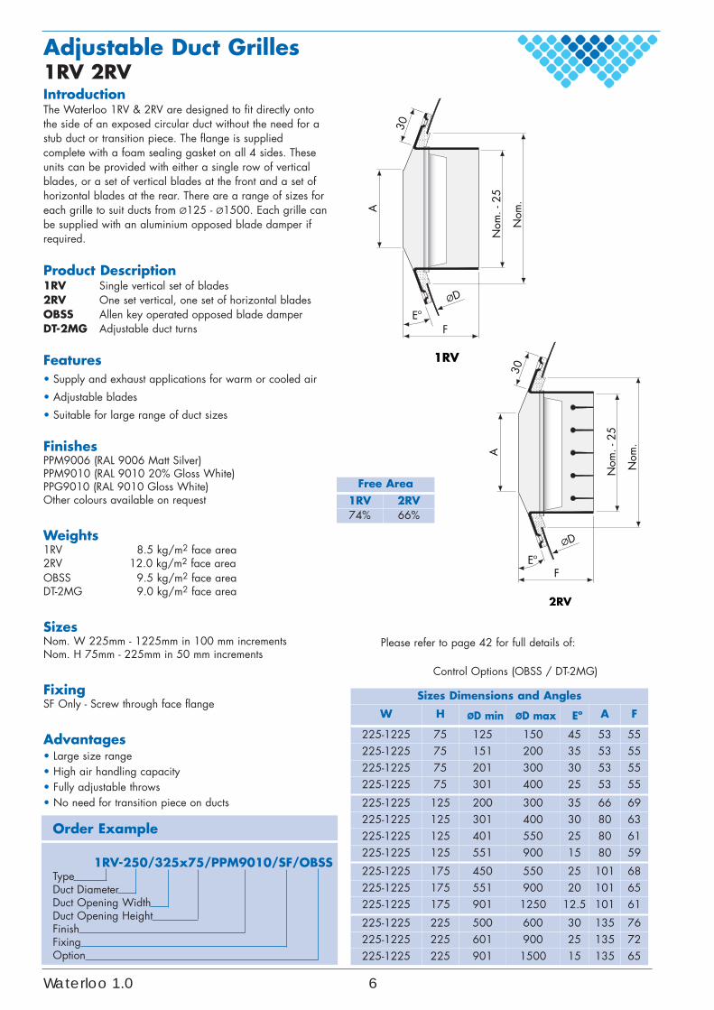
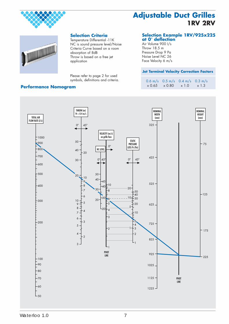
IntroductionThe Waterloo 1RV & 2RV are designed to fit directly ontothe side of an exposed circular duct without the need for astub duct or transition piece. The flange is suppliedcomplete with a foam sealing gasket on all 4 sides. Theseunits can be provided with either a single row of verticalblades, or a set of vertical blades at the front and a set ofhorizontal blades at the rear. There are a range of sizes foreach grille to suit ducts from Ø125 - Ø1500. Each grille canbe supplied with an aluminium opposed blade damper ifrequired.
Product Description1RV Single vertical set of blades2RV One set vertical, one set of horizontal bladesOBSS Allen key operated opposed blade damperDT-2MG Adjustable duct turns
Features• Supply and exhaust applications for warm or cooled air
• Adjustable blades
• Suitable for large range of duct sizes
FinishesPPM9006 (RAL 9006 Matt Silver)PPM9010 (RAL 9010 20% Gloss White)PPG9010 (RAL 9010 Gloss White)Other colours available on request
Weights1RV 8.5 kg/m2 face area2RV 12.0 kg/m2 face areaOBSS 9.5 kg/m2 face areaDT-2MG 9.0 kg/m2 face area
SizesNom. W 225mm - 1225mm in 100 mm incrementsNom. H 75mm - 225mm in 50 mm increments
FixingSF Only - Screw through face flange
Advantages• Large size range• High air handling capacity• Fully adjustable throws• No need for transition piece on ducts
Order Example
1RV-250/325x75/PPM9010/SF/OBSSTypeDuct DiameterDuct Opening WidthDuct Opening HeightFinishFixingOption
Sizes Dimensions and Angles
W H ØD min ØD max Eº A F
225-1225 75 125 150 45 53 55225-1225 75 151 200 35 53 55225-1225 75 201 300 30 53 55225-1225 75 301 400 25 53 55
225-1225 125 200 300 35 66 69225-1225 125 301 400 30 80 63225-1225 125 401 550 25 80 61225-1225 125 551 900 15 80 59
225-1225 175 450 550 25 101 68225-1225 175 551 900 20 101 65225-1225 175 901 1250 12.5 101 61
225-1225 225 500 600 30 135 76225-1225 225 601 900 25 135 72225-1225 225 901 1500 15 135 65
Adjustable Duct Grilles1RV 2RV
Please refer to page 42 for full details of:
Control Options (OBSS / DT-2MG)
ØD
1RV
30
FEº
Nom
. - 2
5
A
Nom
.
ØD
2RV
30
FEº
Nom
. - 2
5
A
Nom
.
Free Area1RV 2RV74% 66%
Waterloo 1.0 6
Performance Nomogram
Please refer to page 2 for usedsymbols, definitions and criteria.
Adjustable Duct Grilles1RV 2RV
325
425
525
625
725
825
925
1025
1125
1225
75
125
175
225
100050
40
30
20
1098
7
6
5
4
3
3
2
4
5
6
7
8910
20
20
30
40
20
30
40
4510
10
543
2
1
20
20
10
5
1
3040508
6
5
4
3
2
1
50
900
800
700
600
500
400
300
200
100
90
80
70
60
50
TOTAL AIRFLOW RATE (l/s)
NOMINALWIDTH(mm)
NOMINALHEIGHT(mm)
0º 45º
PIVOTLINE
PIVOTLINE
THROW (m)Vt = 0.4 m/s
0º
0º 45º
NC LEVEL
0º 45º
STATICPRESSURE
LOSS Ps (Pa)
VELOCITY (m/s)on grille face
Selection Example 1RV/925x225at 0º deflectionAir Volume 900 I/sThrow 18.5 mPressure Drop 9 PaNoise Level NC 26Face Velocity 6 m/s
Selection CriteriaTemperature Differential -11KNC is sound pressure level/NoiseCriteria Curve based on a roomabsorption of 8dBThrow is based on a free jetapplication
0.6 m/s 0.5 m/s 0.4 m/s 0.3 m/sx 0.65 x 0.80 x 1.0 x 1.3
Jet Terminal Velocity Correction Factors
Waterloo 1.0 7
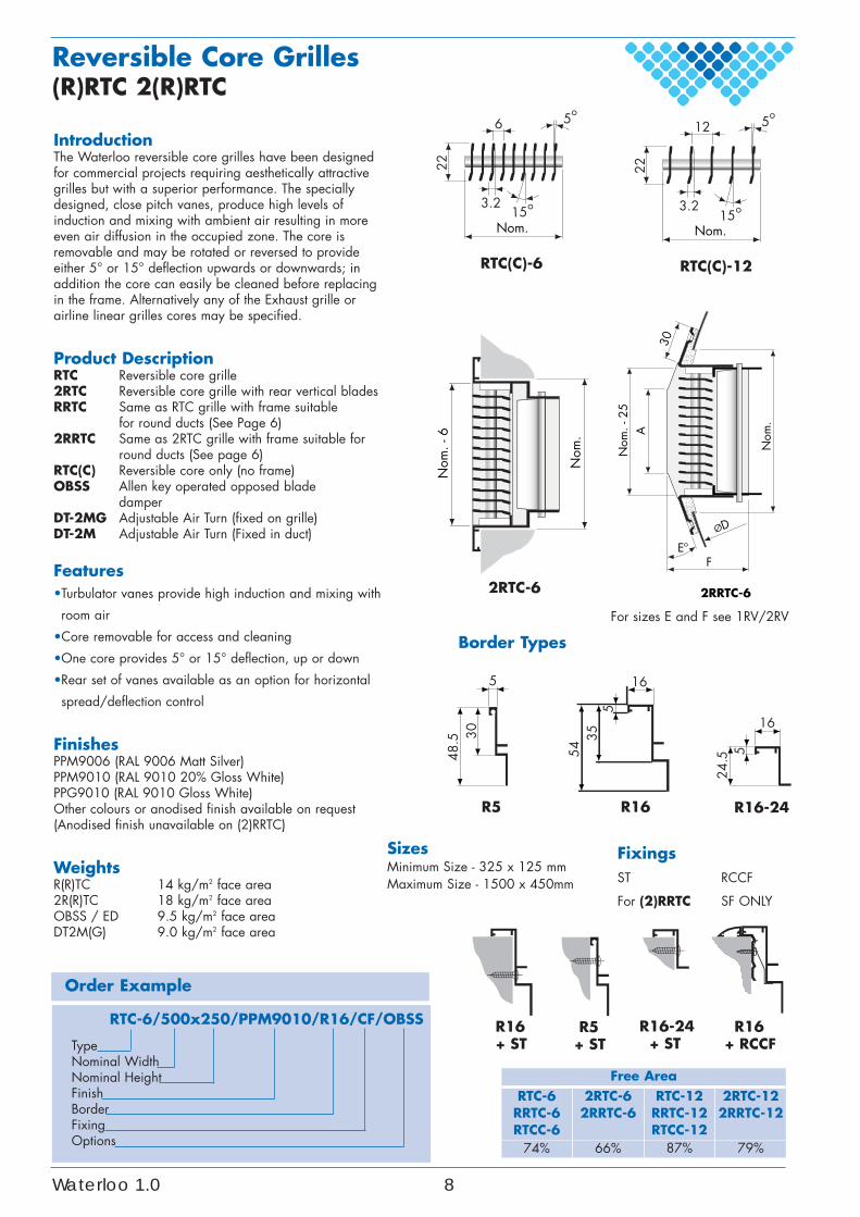
IntroductionThe Waterloo reversible core grilles have been designedfor commercial projects requiring aesthetically attractivegrilles but with a superior performance. The speciallydesigned, close pitch vanes, produce high levels ofinduction and mixing with ambient air resulting in moreeven air diffusion in the occupied zone. The core isremovable and may be rotated or reversed to provideeither 5° or 15° deflection upwards or downwards; inaddition the core can easily be cleaned before replacingin the frame. Alternatively any of the Exhaust grille orairline linear grilles cores may be specified.
Product DescriptionRTC Reversible core grille2RTC Reversible core grille with rear vertical blades RRTC Same as RTC grille with frame suitable
for round ducts (See Page 6)2RRTC Same as 2RTC grille with frame suitable for
round ducts (See page 6)RTC(C) Reversible core only (no frame)OBSS Allen key operated opposed blade
damperDT-2MG Adjustable Air Turn (fixed on grille)DT-2M Adjustable Air Turn (Fixed in duct)
Features•Turbulator vanes provide high induction and mixing with
room air
•Core removable for access and cleaning
•One core provides 5° or 15° deflection, up or down
•Rear set of vanes available as an option for horizontal
spread/deflection control
FinishesPPM9006 (RAL 9006 Matt Silver)PPM9010 (RAL 9010 20% Gloss White)PPG9010 (RAL 9010 Gloss White)Other colours or anodised finish available on request(Anodised finish unavailable on (2)RRTC)
WeightsR(R)TC 14 kg/m2 face area2R(R)TC 18 kg/m2 face areaOBSS / ED 9.5 kg/m2 face areaDT2M(G) 9.0 kg/m2 face area
Order Example
RTC-6/500x250/PPM9010/R16/CF/OBSS
TypeNominal WidthNominal HeightFinishBorderFixingOptions
SizesMinimum Size - 325 x 125 mmMaximum Size - 1500 x 450mm
Reversible Core Grilles(R)RTC 2(R)RTC
Free AreaRTC-6RRTC-6RTCC-6
2RTC-62RRTC-6
RTC-12RRTC-12RTCC-12
2RTC-122RRTC-12
74% 66% 87% 79%
o56
3.2
22
RTC(C)-6
o15Nom.
o512
3.2
22
RTC(C)-12
o15Nom.
2RTC-6N
om.
Nom
. - 6
ØD
2RRTC-6
30
FEº
Nom
. - 2
5A
Nom
.
48.5 30
5
R5
16
535
54
R16
165
24.5
R16-24
Border Types
R16-24 + ST
R16+ ST
R5+ ST
R16+ RCCF
FixingsST RCCF
For (2)RRTC SF ONLY
For sizes E and F see 1RV/2RV
Waterloo 1.0 8
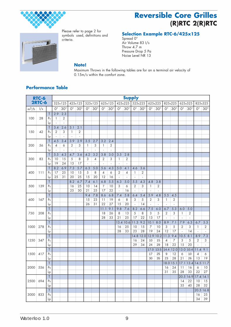
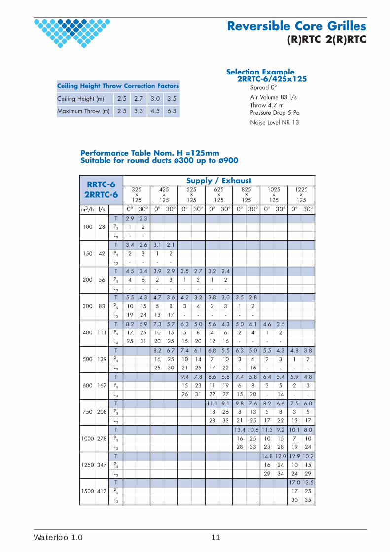
Performance Table
Selection Example RTC-6/425x125Spread 0°Air Volume 83 I/sThrow 4.7 mPressure Drop 5 PaNoise Level NR 13
Please refer to page 2 forsymbols used, definitions andcriteria.
Reversible Core Grilles(R)RTC 2(R)RTC
Note!Maximum Throws in the following tables are for an a terminal air velocity of0.15m/s within the comfort zone.
RTC-62RTC-6
Supply325x125 425x125 525x125 625x125 425x225 525x225 625x225 825x225 625x325 825x325
m3/h l/s 0° 30° 0° 30° 0° 30° 0° 30° 0° 30° 0° 30° 0° 30° 0° 30° 0° 30° 0° 30°
100 28T 2.9 2.3Ps 1 2Lp - -
150 42T 3.4 2.6 3.1 2.1Ps 2 3 1 2Lp - - - -
200 56T 4.5 3.4 3.9 2.9 3.5 2.7 3.2 2.4Ps 4 6 2 3 1 3 1 2Lp - - - - - - - -
300 83T 5.5 4.3 4.7 3.6 4.2 3.2 3.8 3.0 3.5 2.8Ps 10 15 5 8 3 4 2 3 1 2Lp 19 24 13 17 - - - - - -
400 111T 8.2 6.9 7.3 5.7 6.3 5.0 5.6 4.3 5.0 4.1 4.6 3.6Ps 17 25 10 15 5 8 4 6 2 4 1 2Lp 25 31 20 25 15 20 12 16 - - - -
500 139T 8.2 6.7 7.4 6.1 6.8 5.5 6.3 5.0 5.5 4.3 4.8 3.8Ps 16 25 10 14 7 10 3 6 2 3 1 2Lp 25 30 21 25 17 22 - 16 - - - -
600 167T 9.4 7.8 8.6 6.8 7.4 5.8 6.4 5.4 5.9 4.8 5.5 4.5Ps 15 23 11 19 6 8 3 5 2 3 1 2Lp 26 31 22 27 15 20 - 14 - - - -
750 208T 11.1 9.1 9.8 7.6 8.2 6.6 7.5 6.0 6.7 5.3 6.0 5.0Ps 18 26 8 13 5 8 3 5 2 3 1 2Lp 28 33 21 25 17 22 13 17 - - - -
1000 278T 13.4 10.6 11.3 9.2 10.1 8.0 8.9 7.1 7.9 6.3 6.7 5.3Ps 16 25 10 15 7 10 3 5 2 3 1 2Lp 28 33 23 28 19 24 12 17 - 14 - -
1250 347T 14.8 12.0 12.9 10.2 11.3 9.4 10.5 8.1 8.9 7.3Ps 16 24 10 15 4 7 3 5 2 3Lp 29 34 24 29 18 22 15 20 - -
1500 417T 17.0 13.5 14.4 12.0 13.0 10.4 11.4 9.1Ps 17 25 9 12 6 10 4 6Lp 30 35 23 28 21 26 13 19
2000 556T 18.0 15.1 17.1 13.4 14.5 11.7Ps 16 24 11 16 6 10Lp 31 35 28 33 22 27
2500 694T 20.5 16.9 17.4 14.1Ps 14 22 10 15Lp 35 40 28 32
3000 833T 20.5 16.8Ps 16 25Lp 34 39
Waterloo 1.0 9
Reversible Core Grilles(R)RTC 2(R)RTC
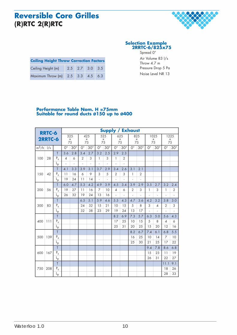
Performance Table Nom. H =75mmSuitable for round ducts Ø150 up to Ø400
Ceiling Height Throw Correction Factors
Ceiling Height (m) 2.5 2.7 3.0 3.5
Maximum Throw (m) 2.5 3.3 4.5 6.3
RRTC-62RRTC-6
Supply / Exhaust325
x75
425x
75
525x
75
625x
75
825x
75
1025x
75
1225x
75
m3/h l/s 0° 30° 0° 30° 0° 30° 0° 30° 0° 30° 0° 30° 0° 30°
100 28T 3.6 2.8 3.4 2.7 3.2 2.5 2.9 2.3Ps 4 6 2 3 1 3 1 2Lp - - - - - - - -
150 42T 4.1 3.3 3.9 3.1 3.7 2.9 3.4 2.6 3.1 2.1Ps 11 16 6 9 3 5 2 3 1 2Lp 19 24 11 14 - - - - - -
200 56T 6.0 4.7 5.3 4.2 4.9 3.9 4.5 3.4 3.9 2.9 3.5 2.7 3.2 2.4Ps 19 27 11 16 7 10 4 6 2 3 1 3 1 2Lp 26 32 19 24 13 16 - - - - - - - -
300 83T 6.5 5.1 5.9 4.6 5.5 4.3 4.7 3.6 4.2 3.2 3.8 3.0Ps 24 32 15 21 10 15 5 8 3 4 2 3Lp 32 38 23 29 19 24 13 17 - - - -
400 111T 8.2 6.9 7.3 5.7 6.3 5.0 5.6 4.3Ps 17 25 10 15 5 8 4 6Lp 25 31 20 25 15 20 12 16
500 139T 8.2 6.7 7.4 6.1 6.8 5.5Ps 16 25 10 14 7 10Lp 25 30 21 25 17 22
600 167T 9.4 7.8 8.6 6.8Ps 15 23 11 19Lp 26 31 22 27
750 208T 11.1 9.1Ps 18 26Lp 28 33
Selection Example 2RRTC-6/825x75
Spread 0°
Air Volume 83 l/sThrow 4.7 m Pressure Drop 5 Pa
Noise Level NR 13
Waterloo 1.0 10
Reversible Core Grilles(R)RTC 2(R)RTC
RRTC-62RRTC-6
Supply / Exhaust325
x125
425x
125
525x
125
625x
125
825x
125
1025x
125
1225x
125
m3/h l/s 0° 30° 0° 30° 0° 30° 0° 30° 0° 30° 0° 30° 0° 30°
100 28
T 2.9 2.3Ps 1 2Lp - -
150 42
T 3.4 2.6 3.1 2.1Ps 2 3 1 2Lp - - - -
200 56
T 4.5 3.4 3.9 2.9 3.5 2.7 3.2 2.4Ps 4 6 2 3 1 3 1 2Lp - - - - - - - -
300 83
T 5.5 4.3 4.7 3.6 4.2 3.2 3.8 3.0 3.5 2.8Ps 10 15 5 8 3 4 2 3 1 2Lp 19 24 13 17 - - - - - -
400 111
T 8.2 6.9 7.3 5.7 6.3 5.0 5.6 4.3 5.0 4.1 4.6 3.6Ps 17 25 10 15 5 8 4 6 2 4 1 2Lp 25 31 20 25 15 20 12 16 - - - -
500 139
T 8.2 6.7 7.4 6.1 6.8 5.5 6.3 5.0 5.5 4.3 4.8 3.8Ps 16 25 10 14 7 10 3 6 2 3 1 2Lp 25 30 21 25 17 22 - 16 - - - -
600 167
T 9.4 7.8 8.6 6.8 7.4 5.8 6.4 5.4 5.9 4.8Ps 15 23 11 19 6 8 3 5 2 3Lp 26 31 22 27 15 20 - 14 - -
750 208
T 11.1 9.1 9.8 7.6 8.2 6.6 7.5 6.0Ps 18 26 8 13 5 8 3 5Lp 28 33 21 25 17 22 13 17
1000 278
T 13.4 10.6 11.3 9.2 10.1 8.0Ps 16 25 10 15 7 10Lp 28 33 23 28 19 24
1250 347
T 14.8 12.0 12.9 10.2Ps 16 24 10 15Lp 29 34 24 29
1500 417
T 17.0 13.5Ps 17 25Lp 30 35
Performance Table Nom. H =125mmSuitable for round ducts Ø300 up to Ø900
Selection Example 2RRTC-6/425x125
Spread 0°
Air Volume 83 l/sThrow 4.7 m Pressure Drop 5 Pa
Noise Level NR 13
Ceiling Height Throw Correction Factors
Ceiling Height (m) 2.5 2.7 3.0 3.5
Maximum Throw (m) 2.5 3.3 4.5 6.3
Waterloo 1.0 11
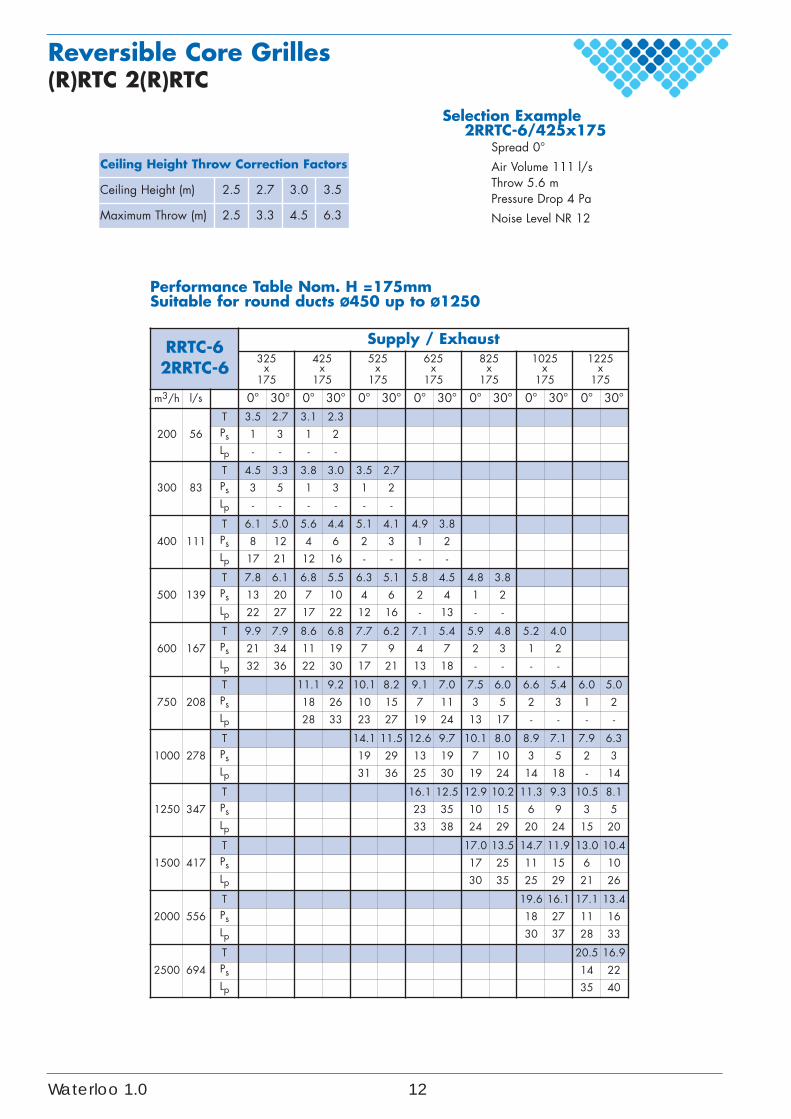
Reversible Core Grilles(R)RTC 2(R)RTC
RRTC-62RRTC-6
Supply / Exhaust325
x175
425x
175
525x
175
625x
175
825x
175
1025x
175
1225x
175
m3/h l/s 0° 30° 0° 30° 0° 30° 0° 30° 0° 30° 0° 30° 0° 30°
200 56
T 3.5 2.7 3.1 2.3Ps 1 3 1 2Lp - - - -
300 83
T 4.5 3.3 3.8 3.0 3.5 2.7Ps 3 5 1 3 1 2Lp - - - - - -
400 111
T 6.1 5.0 5.6 4.4 5.1 4.1 4.9 3.8Ps 8 12 4 6 2 3 1 2Lp 17 21 12 16 - - - -
500 139
T 7.8 6.1 6.8 5.5 6.3 5.1 5.8 4.5 4.8 3.8Ps 13 20 7 10 4 6 2 4 1 2Lp 22 27 17 22 12 16 - 13 - -
600 167
T 9.9 7.9 8.6 6.8 7.7 6.2 7.1 5.4 5.9 4.8 5.2 4.0Ps 21 34 11 19 7 9 4 7 2 3 1 2Lp 32 36 22 30 17 21 13 18 - - - -
750 208
T 11.1 9.2 10.1 8.2 9.1 7.0 7.5 6.0 6.6 5.4 6.0 5.0Ps 18 26 10 15 7 11 3 5 2 3 1 2Lp 28 33 23 27 19 24 13 17 - - - -
1000 278
T 14.1 11.5 12.6 9.7 10.1 8.0 8.9 7.1 7.9 6.3Ps 19 29 13 19 7 10 3 5 2 3Lp 31 36 25 30 19 24 14 18 - 14
1250 347
T 16.1 12.5 12.9 10.2 11.3 9.3 10.5 8.1Ps 23 35 10 15 6 9 3 5Lp 33 38 24 29 20 24 15 20
1500 417
T 17.0 13.5 14.7 11.9 13.0 10.4Ps 17 25 11 15 6 10Lp 30 35 25 29 21 26
2000 556
T 19.6 16.1 17.1 13.4Ps 18 27 11 16Lp 30 37 28 33
2500 694
T 20.5 16.9Ps 14 22Lp 35 40
Performance Table Nom. H =175mmSuitable for round ducts Ø450 up to Ø1250
Selection Example 2RRTC-6/425x175
Spread 0°
Air Volume 111 l/sThrow 5.6 m Pressure Drop 4 Pa
Noise Level NR 12
Ceiling Height Throw Correction Factors
Ceiling Height (m) 2.5 2.7 3.0 3.5
Maximum Throw (m) 2.5 3.3 4.5 6.3
Waterloo 1.0 12
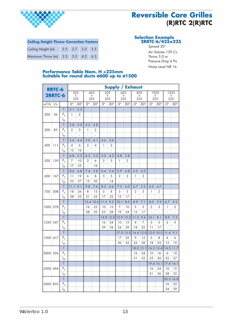
Reversible Core Grilles(R)RTC 2(R)RTC
RRTC-62RRTC-6
Supply / Exhaust325
x225
425x
225
525x
225
625x
225
825x
225
1025x
225
1225x
225
m3/h l/s 0° 30° 0° 30° 0° 30° 0° 30° 0° 30° 0° 30° 0° 30°
200 56
T 3.1 2.3Ps 1 2Lp - -
300 83
T 3.8 3.0 3.5 2.8Ps 2 3 1 2Lp - - - -
400 111
T 5.6 4.4 5.0 4.1 4.6 3.6Ps 4 6 2 4 1 2Lp 12 16 - - - -
500 139
T 6.8 5.5 6.3 5.0 5.5 4.3 4.8 3.8Ps 7 10 3 6 2 3 1 2Lp 17 22 - 16 - - - -
600 167
T 8.6 6.8 7.4 5.8 6.4 5.4 5.9 4.8 5.5 4.5Ps 11 19 6 8 3 5 2 3 1 2Lp 22 27 15 20 - 14 - - - -
750 208
T 11.1 9.1 9.8 7.6 8.2 6.6 7.5 6.0 6.7 5.3 6.0 4.7Ps 18 26 8 13 5 8 3 5 2 3 1 2Lp 28 33 21 25 17 22 13 17 - - - -
1000 278
T 13.4 10.6 11.3 9.2 10.1 8.0 8.9 7.1 8.0 5.9 6.7 5.3Ps 16 25 10 15 7 10 3 5 2 3 1 2Lp 28 33 23 28 19 24 12 17 - - - -
1250 347
T 14.8 12.0 12.9 10.2 11.3 9.4 10.1 8.1 8.9 7.3Ps 16 24 10 15 4 7 3 5 2 3Lp 29 34 24 29 18 22 11 17 - -
1500 417
T 17.0 13.5 14.4 12.0 12.9 10.5 11.4 9.1Ps 17 25 9 12 5 8 4 6Lp 30 35 23 28 18 23 13 19
2000 556
T 18.0 15.1 16.3 13.4 14.5 11.7Ps 16 24 10 16 6 10Lp 31 35 25 30 22 27
2500 694
T 19.4 16.1 17.4 14.1Ps 16 24 10 15Lp 31 36 28 32
3000 833
T 20.5 16.8Ps 16 25Lp 34 39
Performance Table Nom. H =225mmSuitable for round ducts Ø600 up to Ø1500
Selection Example 2RRTC-6/425x225
Spread 30°
Air Volume 139 l/sThrow 5.0 m Pressure Drop 6 Pa
Noise Level NR 16
Ceiling Height Throw Correction Factors
Ceiling Height (m) 2.5 2.7 3.0 3.5
Maximum Throw (m) 2.5 3.3 4.5 6.3
Waterloo 1.0 13
Fixing OptionsSF CF CRB VS AFVSPFVS RCHS AFHS AFCF RCCFBSSBD BSSBP
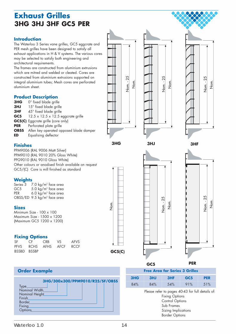
IntroductionThe Waterloo 3 Series vane grilles, GC5 eggcrate andPER mesh grilles have been designed to satisfy allexhaust applications in H & V systems. The various coresmay be selected to satisfy both engineering andarchitectural requirements.The frames are constructed from aluminium extrusionswhich are mitred and welded or cleated. Cores areconstructed from aluminium extrusions supported onintegral aluminium tubes; Mesh cores are perforatedaluminium sheet.
Product Description3HG 0° fixed blade grille3HJ 15° fixed blade grille3HF 45° fixed blade grilleGC5 12.5 x 12.5 x 12.5 eggcrate grilleGC5(C) Eggcrate grille (core only)PER Perforated plate grilleOBSS Allen key operated opposed blade damperED Equalising deflector
FinishesPPM9006 (RAL 9006 Matt Silver)PPM9010 (RAL 9010 20% Gloss White)PPG9010 (RAL 9010 Gloss White)Other colours or anodised finish available on requestGC5/(C) Core is mill finished as standard
WeightsSeries 3 7.0 kg/m2 face areaGC5 5.0 kg/m2 face areaPER 6.0 kg/m2 face areaOBSS/ED 9.5 kg/m2 face area
SizesMinimum Size - 100 x 100Maximum Size - 1500 x 1200(Maximum GC5 1200 x 1200)
Order Example
3HG/300x300/PPM9010/R25/SF/OBSSTypeNominal WidthNominal HeightFinishBorderFixingOptions
Free Area for Series 3 Grilles
3HG 3HJ 3HF GC5 PER
84% 84% 54% 91% 51%
Exhaust Grilles3HG 3HJ 3HF GC5 PER
Please refer to pages 40-43 for full details of:Fixing OptionsControl OptionsSub FramesSizing ImplicationsBorder Options
Nom
. - 2
5
Nom
.
3HG 3HJ
Nom
. - 2
5
Nom
.
Nom
. - 2
5
Nom
.
3HF
GC5(C)
Nom
.
GC5
Nom
. - 2
5
Nom
.
PER
Nom
. - 2
5
Nom
.
Waterloo 1.0 14
100
200
300
400
50
40
30
20
50
40
30
20
50
10
100
50
10
5
2
100
50
10
5
2
54
3
2
1
500
400
300
250
100
200
600
700
800
900
1000
1200
1500
40
30
20
500
600
700
8009001000
2000
3000
4000
5000
50
25
100
50
10
5
2
150
200
250
300
400
500
600
1000
1200
AIR FLOWRATE(l/s)
NCLevel
NOMINALHEIGHT
(mm)
NOMINALWIDTH(mm)
PivotLine
PivotLine
PIV
OT
LIN
E
Velocity (m/s)25mm fromgrille face
3HG3HJ
PERGC5
3HF
Pressure LossPs (Pa)
3HF PER 3HG3HJGC5
Exhaust Grilles3HG 3HJ 3HF GC5 PER
Performance Nomogram
Please refer to page 2 for usedsymbols, definitions and criteria.
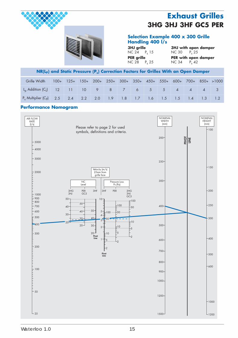
Selection Example 400 x 300 GrilleHandling 400 l/s3HJ grille 3HJ with open damperNC 24 Ps 15 NC 30 Ps 25PER grille PER with open damperNC 28 Ps 25 NC 34 Ps 42
NR(Lp) and Static Pressure (Ps) Correction Factors for Grilles With an Open Damper
Grille Width 100+ 125+ 150+ 200+ 250+ 300+ 350+ 450+ 550+ 600+ 700+ 850+ >1000
Lp Addition (CL) 12 11 10 9 8 7 6 5 5 4 4 4 3
Ps Multiplier (CP) 2.5 2.4 2.2 2.0 1.9 1.8 1.7 1.6 1.5 1.5 1.4 1.3 1.2
Waterloo 1.0 15
Fixing OptionsControl Options.Sub FramesSizing ImplicationsBorder Options
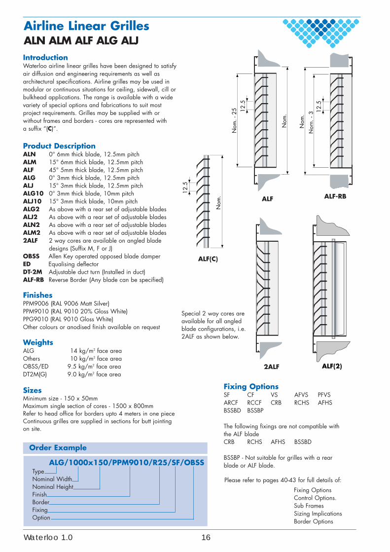
IntroductionWaterloo airline linear grilles have been designed to satisfyair diffusion and engineering requirements as well asarchitectural specifications. Airline grilles may be used inmodular or continuous situations for ceiling, sidewall, cill orbulkhead applications. The range is available with a widevariety of special options and fabrications to suit mostproject requirements. Grilles may be supplied with orwithout frames and borders - cores are represented with a suffix “(C)”.
Product DescriptionALN 0° 6mm thick blade, 12.5mm pitch ALM 15° 6mm thick blade, 12.5mm pitch ALF 45° 5mm thick blade, 12.5mm pitch ALG 0° 3mm thick blade, 12.5mm pitchALJ 15° 3mm thick blade, 12.5mm pitchALG10 0° 3mm thick blade, 10mm pitch ALJ10 15° 3mm thick blade, 10mm pitchALG2 As above with a rear set of adjustable bladesALJ2 As above with a rear set of adjustable bladesALN2 As above with a rear set of adjustable bladesALM2 As above with a rear set of adjustable blades2ALF 2 way cores are available on angled blade
designs (Suffix M, F or J)OBSS Allen Key operated opposed blade damperED Equalising deflectorDT-2M Adjustable duct turn (Installed in duct)ALF-RB Reverse Border (Any blade can be specified)
FinishesPPM9006 (RAL 9006 Matt Silver)PPM9010 (RAL 9010 20% Gloss White)PPG9010 (RAL 9010 Gloss White)Other colours or anodised finish available on request
WeightsALG 14 kg/m2 face areaOthers 10 kg/m2 face areaOBSS/ED 9.5 kg/m2 face areaDT2M(G) 9.0 kg/m2 face area
SizesMinimum size - 150 x 50mmMaximum single section of cores - 1500 x 800mmRefer to head office for borders upto 4 meters in one pieceContinuous grilles are supplied in sections for butt jointingon site.
ALG/1000x150/PPM9010/R25/SF/OBSSTypeNominal WidthNominal HeightFinishBorderFixingOption
Order Example
Fixing OptionsSF CF VS AFVS PFVSARCF RCCF CRB RCHS AFHSBSSBD BSSBP
The following fixings are not compatible withthe ALF bladeCRB RCHS AFHS BSSBD
BSSBP - Not suitable for grilles with a rearblade or ALF blade.
Please refer to pages 40-43 for full details of:
Airline Linear GrillesALN ALM ALF ALG ALJ
Special 2 way cores areavailable for all angledblade configurations, i.e.2ALF as shown below.
ALF(C)
Nom
.
12.5
Nom
. - 2
5
Nom
.
ALF
12.5
2ALF ALF(2)
Nom
. - 3
Nom
.
ALF-RB
12.5
Waterloo 1.0 16
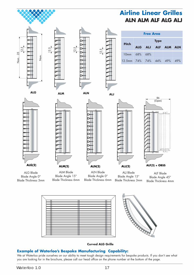
Free Area
PitchType
ALG ALJ ALF ALM ALN
10mm 68% 68%
12.5mm 74% 74% 44% 49% 49%
Airline Linear GrillesALN ALM ALF ALG ALJ
Nom
. - 2
5
Nom
.
ALG
12.5
ALM
12.5
ALN
12.5
ALJ
12.5
86(Open)
ALF(2) + OBSSALM(2)ALG(2) ALN(2) ALJ(2)
ALG BladeBlade Angle 0°
Blade Thickness 3mm
ALM BladeBlade Angle 15°
Blade Thickness 6mm
ALN BladeBlade Angle 0°
Blade Thickness 6mm
ALJ BladeBlade Angle 15°
Blade Thickness 3mm
ALF BladeBlade Angle 45°
Blade Thickness 4mm
Curved ALG Grille
Example of Waterloo’s Bespoke Manufacturing Capability:We at Waterloo pride ourselves on our ability to meet tough design requirements for bespoke products. If you don’t see whatyou are looking for in the brochure, please call our head office on the phone number at the bottom of the page.
Waterloo 1.0 17
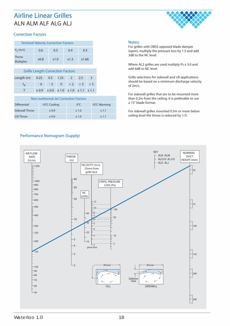
Grille Length Correction Factors
Length (m) 0.25 0.5 1.25 2 2.5 3
Lp - 6 - 3 0 + 2 + 3 + 5
T x 0.9 x 0.9 x 1.0 x 1.0 x 1.1 x 1.1
Notes:For grilles with OBSS opposed blade damper(open), multiply the pressure loss by 1.5 and add3dB to the NC level.
Where AL2 grilles are used multiply Ps x 3.0 andadd 6dB to NC level.
Grille selections for sidewall and cill applicationsshould be based on a minimum discharge velocityof 2m/s.
For sidewall grilles that are to be mounted morethan 0.2m from the ceiling, it is preferable to usea 15° blade format.
For sidewall grilles mounted 0.5m or more belowceiling level the throw is reduced by 1/3.
Airline Linear GrillesALN ALM ALF ALG ALJ
Performance Nomogram (Supply)
Terminal Velocity Correction Factors
Vt (m/s) 0.6 0.5 0.4 0.3
ThrowMultiplier
x0.8 x1.0 x1.3 x1.66
Non-isothermal Jet Correction Factors
Differential 10°C Cooling 0°C 10°C Warming
Sidewall Throw x 0.9 x 1.0 x 1.1
Cill Throw x 0.9 x 1.0 x 1.1
Correction Factors
1500
1000900
800
700
600
500
400
300
250
200
150
1009080
70
60
50
40
13
100
50
10
5
10
8765
4
3
2
30
20
10
50
75
100
150
200
300
40
30
20
10
5
4
3
2
AIR FLOWRATE
(l/s/m)THROW
(m)
NCLEVEL
STATIC PRESSURELOSS (Pa)
VELOCITY (m/s)25mm fromgrille face
NOMINALDUCT
HEIGHT (mm)
KEYALN ALMALG10 ALJ10ALG ALJ
pivot line
CILL
throw
SIDEWALL
throw
500mmmax
810.1oolretaW
1500
1000900800700
600
500
400
300
250
150
100908070
60
50
40
30
25
20
15
10
200
50
40
30
20
10
50
40
30
20
10
50
1087654
340
30
20
10
50
50 50 50
50
75
100
150
200
300
10
1010 10
5
55 5
1
1 1 1
100
100 100 100
200
200200 200
2
1
0.5
NOMINALDUCT
HEIGHT (mm)
AIR FLOWRATE
(l/s/m)
NCLEVEL
ALGALJALNALM
ALG 10ALJ 10
ALF ALF ALNALM
ALG10ALJ10
ALGALJ
VELOCITY (m/s)25mm fromgrille face
STATIC PRESSURELOSS (Pa)
Pivot line
Pivot line
Please refer to page 2 for used symbols, definitions and criteria.
Airline Linear GrillesALN ALM ALF ALG ALJ
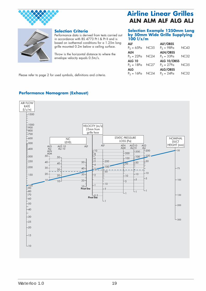
Selection Example 1250mm Longby 50mm Wide Grille Supplying100 l/s/mALF ALF/OBSSPS = 65Pa NC35 PS = 98Pa NC43ALN ALN/OBSSPS = 22Pa NC24 PS = 33Pa NC32ALG 10 ALG 10/OBSSPS = 18Pa NC27 PS = 27Pa NC35ALG ALG/OBSSPS = 16Pa NC24 PS = 24Pa NC32
Performance Nomogram (Exhaust)
Selection CriteriaPerformance data is derived from tests carried outin accordance with BS 4773 Pt I & Pt II and isbased on isothermal conditions for a 1.25m longgrille mounted 0.2m below a ceiling surface.
Throw is the horizontal distance to where theenvelope velocity equals 0.5m/s.
Waterloo 1.0 19
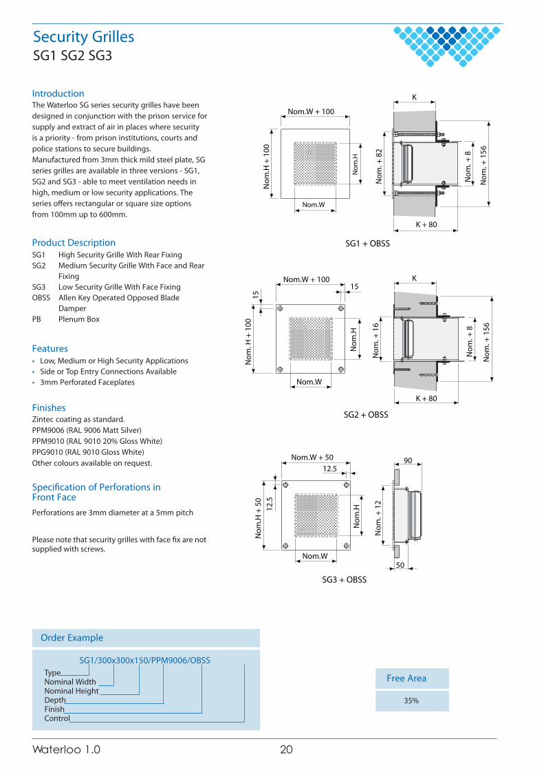
IntroductionThe Waterloo SG series security grilles have beendesigned in conjunction with the prison service forsupply and extract of air in places where securityis a priority - from prison institutions, courts andpolice stations to secure buildings.Manufactured from 3mm thick mild steel plate, SGseries grilles are available in three versions - SG1,SG2 and SG3 - able to meet ventilation needs inhigh, medium or low security applications. Theseries o�ers rectangular or square size optionsfrom 100mm up to 600mm.
Product DescriptionSG1 High Security Grille With Rear FixingSG2 Medium Security Grille With Face and Rear
FixingSG3 Low Security Grille With Face FixingOBSS Allen Key Operated Opposed Blade
DamperPB Plenum Box
Features• Low, Medium or High Security Applications• Side or Top Entry Connections Available• 3mm Perforated Faceplates
FinishesZintec coating as standard.PPM9006 (RAL 9006 Matt Silver)PPM9010 (RAL 9010 20% Gloss White)PPG9010 (RAL 9010 Gloss White)Other colours available on request.
Speci�cation of Perforations inFront FacePerforations are 3mm diameter at a 5mm pitch
Please note that security grilles with face �x are notsupplied with screws.
Order Example
SG1/300x300x150/PPM9006/OBSSTypeNominal WidthNominal HeightDepthFinishControl
Security GrillesSG1 SG2 SG3
Free Area
35%
Nom
. + 8
Nom
. + 1
56
Nom.W + 100
Nom
. + 8
2
SG1 + OBSS
K + 80
Nom
.H +
100
K
Nom
.H
Nom.W
K
Nom
. + 8
Nom
. + 1
56
Nom
. + 1
6
Nom
.H
K + 80
Nom.W + 10015
15
Nom.W
Nom
. H +
100
SG2 + OBSS
Nom
. + 1
2
50
90Nom.W + 50
12.5
Nom
.H +
50
12.5
SG3 + OBSS
Nom
.H
Nom.W
020.1 oolretaW
Security GrillesSG1 SG2 SG3
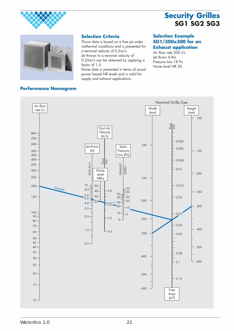
Selection Example SG1/300x300 for anExhaust applicationAir flow rate 200 l/sJet throw 4.8mPressure loss 18 PaNoise level NR 20
Selection CriteriaThrow data is based on a free jet underisothermal conditions and is presented fora terminal velocity of 0.5m/s.Jet throws to a terminal velocity of0.25m/s can be obtained by applying afactor of 1.5.Noise data is presented in terms of soundpower based NR levels and is valid forsupply and exhaust applications
100
150
Pivo
tLin
e
0.005
0.006
200
250
0.008
0.01
0.015
0.02
100
150
200
70
2030
50
Line
7050
4.0
50
20
30
40
Pivo
t
800
700
600
500450
10
400
350
300
250
200
150 6.05.0
8.0
300
400
0.03
0.05
0.04
600
0.08
0.1
0.15
500
250
10
5
300
20
10
2.0
51.0
0.5
400
500
600
10090
80
60
5045
70
35
25
30
20
15
40
10
3.0
2.0
1.0
0.5
304.0
SUPP
LY
EXH
AU
ST
Vt=0
.5m
/s
Air flowrate l/s
Jet throw(m)
Width(mm)
Height(mm)
Duct AirVelocity(m/s)
StaticPressureLoss (Pa)
FreeArea(m2)
NoiseLevelNRlw
Nominal Grille Size
Example
Performance Nomogram
Waterloo 1.0 21
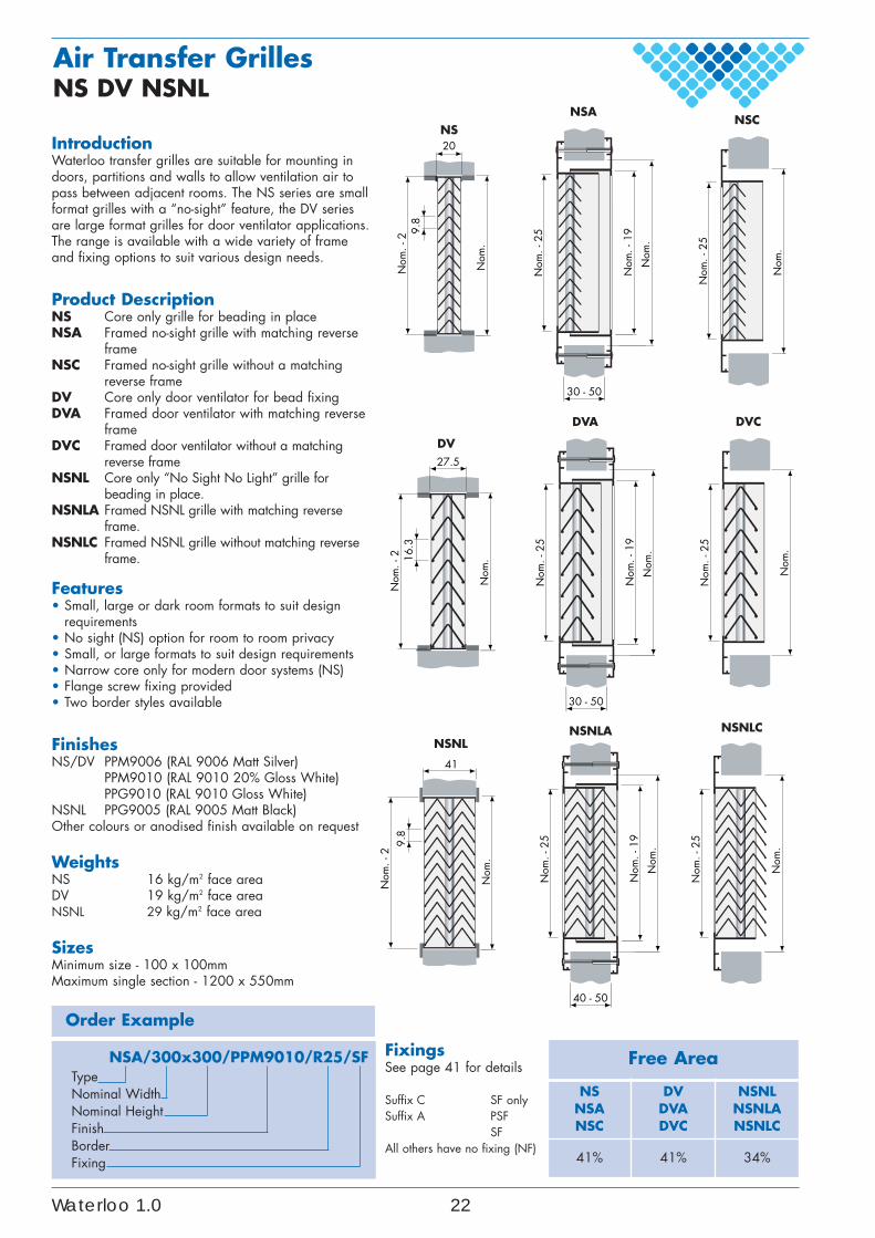
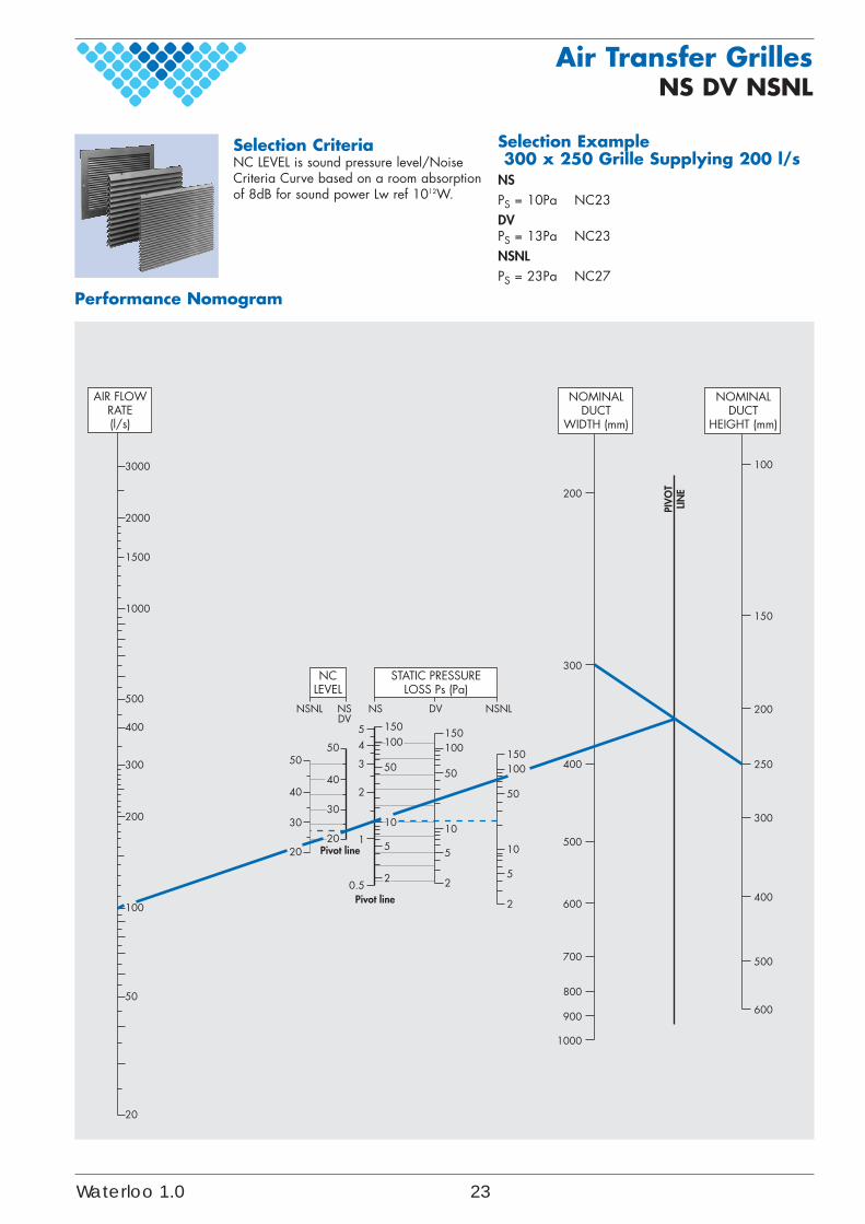
IntroductionWaterloo transfer grilles are suitable for mounting indoors, partitions and walls to allow ventilation air topass between adjacent rooms. The NS series are smallformat grilles with a “no-sight” feature, the DV seriesare large format grilles for door ventilator applications.The range is available with a wide variety of frameand fixing options to suit various design needs.
Product DescriptionNS Core only grille for beading in placeNSA Framed no-sight grille with matching reverse
frameNSC Framed no-sight grille without a matching
reverse frameDV Core only door ventilator for bead fixingDVA Framed door ventilator with matching reverse
frameDVC Framed door ventilator without a matching
reverse frameNSNL Core only “No Sight No Light” grille for
beading in place.NSNLA Framed NSNL grille with matching reverse
frame.NSNLC Framed NSNL grille without matching reverse
frame.
Features• Small, large or dark room formats to suit design
requirements• No sight (NS) option for room to room privacy• Small, or large formats to suit design requirements• Narrow core only for modern door systems (NS)• Flange screw fixing provided• Two border styles available
FinishesNS/DV PPM9006 (RAL 9006 Matt Silver)
PPM9010 (RAL 9010 20% Gloss White)PPG9010 (RAL 9010 Gloss White)
NSNL PPG9005 (RAL 9005 Matt Black)Other colours or anodised finish available on request
WeightsNS 16 kg/m2 face areaDV 19 kg/m2 face areaNSNL 29 kg/m2 face area
SizesMinimum size - 100 x 100mmMaximum single section - 1200 x 550mm
Order Example
NSA/300x300/PPM9010/R25/SFTypeNominal WidthNominal HeightFinishBorderFixing
Air Transfer GrillesNS DV NSNL
Free Area
NSNSANSC
DVDVADVC
NSNLNSNLANSNLC
41% 41% 34%
FixingsSee page 41 for details
Suffix C SF onlySuffix A PSF
SFAll others have no fixing (NF)
NS
Nom
. - 2
Nom
.
9.8
20
NSA
Nom
. - 2
5
Nom
.
Nom
. - 1
9
30 - 50
NSC
Nom
. - 2
5
Nom
.
DV
Nom
. - 2
Nom
.16.3
27.5
DVA
Nom
. - 2
5
Nom
.
Nom
. - 1
9
30 - 50
DVC
Nom
. - 2
5
Nom
.
NSNL
Nom
. - 2
Nom
.
9.8
41
NSNLA
Nom
. - 2
5
Nom
.
Nom
. - 1
9
40 - 50
NSNLC
Nom
. - 2
5
Nom
.
Waterloo 1.0 22
Air Transfer GrillesNS DV NSNL
3000
2000
1000
1500
500
400
300
200
100
50
20
AIR FLOWRATE(l/s)
50
40
30
20
0.5
1
2
2
5
10
50
100150
3
45
50
100
300
40
30
20
NCLEVEL
NSNL NSDV
STATIC PRESSURELOSS Ps (Pa)
NSNLNS DV
2
5
10
50
100150
2
5
10
50
100150
200
400
600
700
800
900
500
1000
150
200
250
300
400
500
600
NOMINALDUCT
HEIGHT (mm)
NOMINALDUCT
WIDTH (mm)
Pivot line
Pivot line
PIV
OT
LIN
E
Performance Nomogram
Selection Example300 x 250 Grille Supplying 200 l/s
NSPS = 10Pa NC23DVPS = 13Pa NC23NSNLPS = 23Pa NC27
Selection CriteriaNC LEVEL is sound pressure level/NoiseCriteria Curve based on a room absorptionof 8dB for sound power Lw ref 1012W.
Waterloo 1.0 23
420.1oolretaW
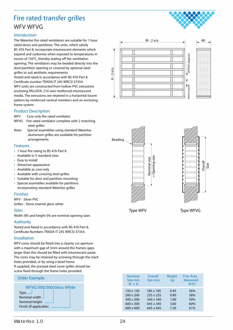
Fire rated transfer grillesWFV WFVGIntroductionThe Waterloo fire rated ventilators are suitable for 1 hourrated doors and partitions. The units, which satisfyBS 476 Part 8, incorporate intumescent elements whichexpand and carbonise when exposed to temperatures inexcess of 150°C, thereby sealing off the ventilationopening. The ventilators may be beaded directly into thedoor/partition opening or covered by optional steelgrilles to suit aesthetic requirements.Tested and rated in accordance with BS 476 Part 8.Certificate number TRADA IT 245 WRCSI 37354.WFV units are constructed from hollow PVC extrusionsenclosing PALUSOL 210 wire reinforced intumescentmedia. The extrusions are retained in a horizontal louvrepattern by reinforced vertical members and an enclosingframe system.
Product DescriptionWFV Core only fire rated ventilatorWFVG Fire rated ventilator complete with 2 matching
steel grillesNote: Special assemblies using standard Waterloo
aluminium grilles are available for partitionarrangements
Features• 1 hour fire rating to BS 476 Part 8• Available in 5 standard sizes• Easy to install• Attractive appearance• Available as core only• Available with covering steel grilles• Suitable for door and partition mounting• Special assemblies available for partitions
incorporating standard Waterloo grilles
FinishesWFV - Silver PVCGrilles - Stove enamel gloss white
SizesWidth (W) and height (H) are nominal opening sizes
AuthorityTested and Rated in accordance with BS 476 Part 8.Certificate Numbers TRADA IT 245 WRCSI 37354.
InstallationWFV cores should be fitted into a cleanly cut aperturewith a maximum gap of 5mm around the frames; gapslarger than this should be filled with intumescent paste.The cores may be retained by screwing through the stackholes provided, or by using a bead frame.If supplied, the pressed steel cover grilles should bescrew fixed through the frame holes provided.
Order Example Nominal Overall Weight Free AreaSize mm Size mm kg Measured
VFWHxW
150 x 150200 x 200300 x 300600 x 300600 x 600
WFVG/300/300/Gloss WhiteTypeNominal widthNominal heightFinish (If applicable)
40W - 2 o/a
H -
2 o/
a
20 P
itch
(App
rox)
6mm
Lou
vre
Ove
rall
Size
Type WFVG
Nom
inal
size
= O
peni
ng si
ze
Beading
Type WFV
56%58%59%60%61%
0.450.801.803.607.20
185 x 185235 x 235340 x 340645 x 340645 x 645
520.1oolretaW
Fire rated transfer grillesWFV WFVG
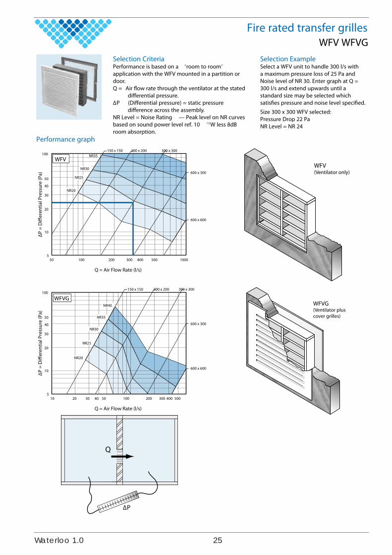
Performance graph
Selection ExampleSelect a WFV unit to handle 300 l/s witha maximum pressure loss of 25 Pa andNoise level of NR 30. Enter graph at Q =300 l/s and extend upwards until astandard size may be selected whichsatisfies pressure and noise level specified.Size 300 x 300 WFV selected:Pressure Drop 22 PaNR Level = NR 24
Selection CriteriaPerformance is based on a ‘room to room’application with the WFV mounted in a partition ordoor.Q = Air flow rate through the ventilator at the stated
differential pressure.ΔP (Differential pressure) = static pressure
difference across the assembly.NR Level = Noise Rating — Peak level on NR curvesbased on sound power level ref. 10 -12W less 8dBroom absorption.
100
40
50
30
20
10
500 100050 100 200 300 4005
Q = Air Flow Rate (l/s)
ΔP
= D
iffer
entia
l Pre
ssur
e (P
a)
150 x 150 200 x 200 300 x 300
600 x 300
600 x 600
NR35
NR30
NR25
NR20
WFV
100
40
50
30
20
10
10 20 30 40 50 100 200 300 400 5005
Q = Air Flow Rate (l/s)
ΔP
= D
iffer
entia
l Pre
ssur
e (P
a)
NR40
NR35
NR30
NR25
NR20
150 x 150 200 x 200 300 x 300
600 x 300
600 x 600
WFVG
Q
ΔP
WFV(Ventilator only)
WFVG(Ventilator pluscover grilles)
620.1oolretaW
Acoustic transfer grillesDSRX
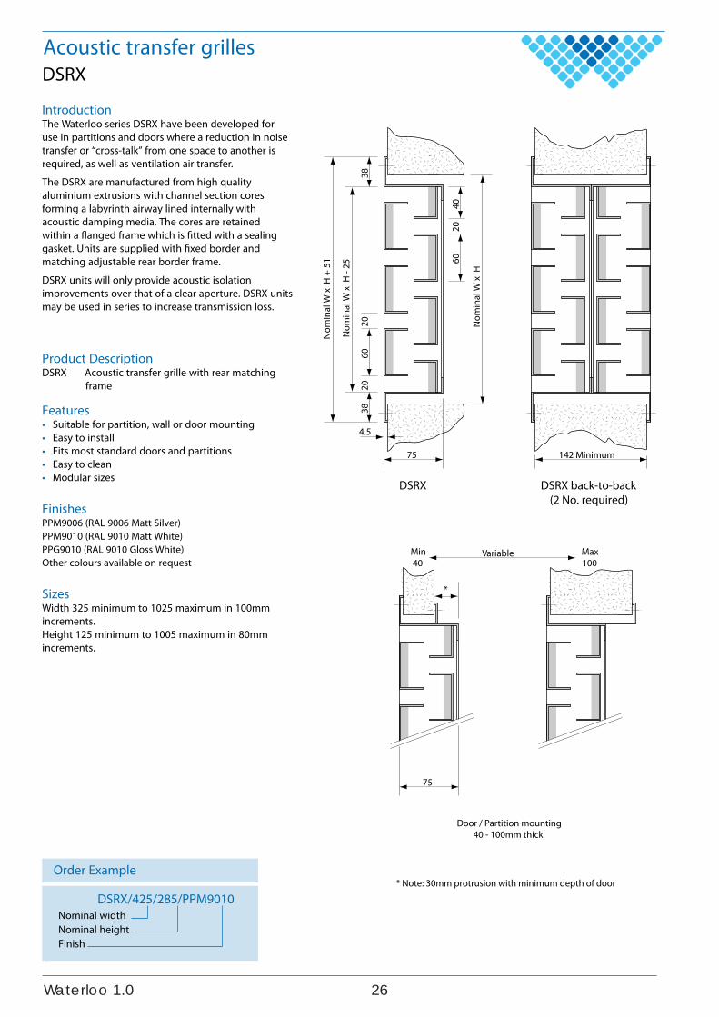
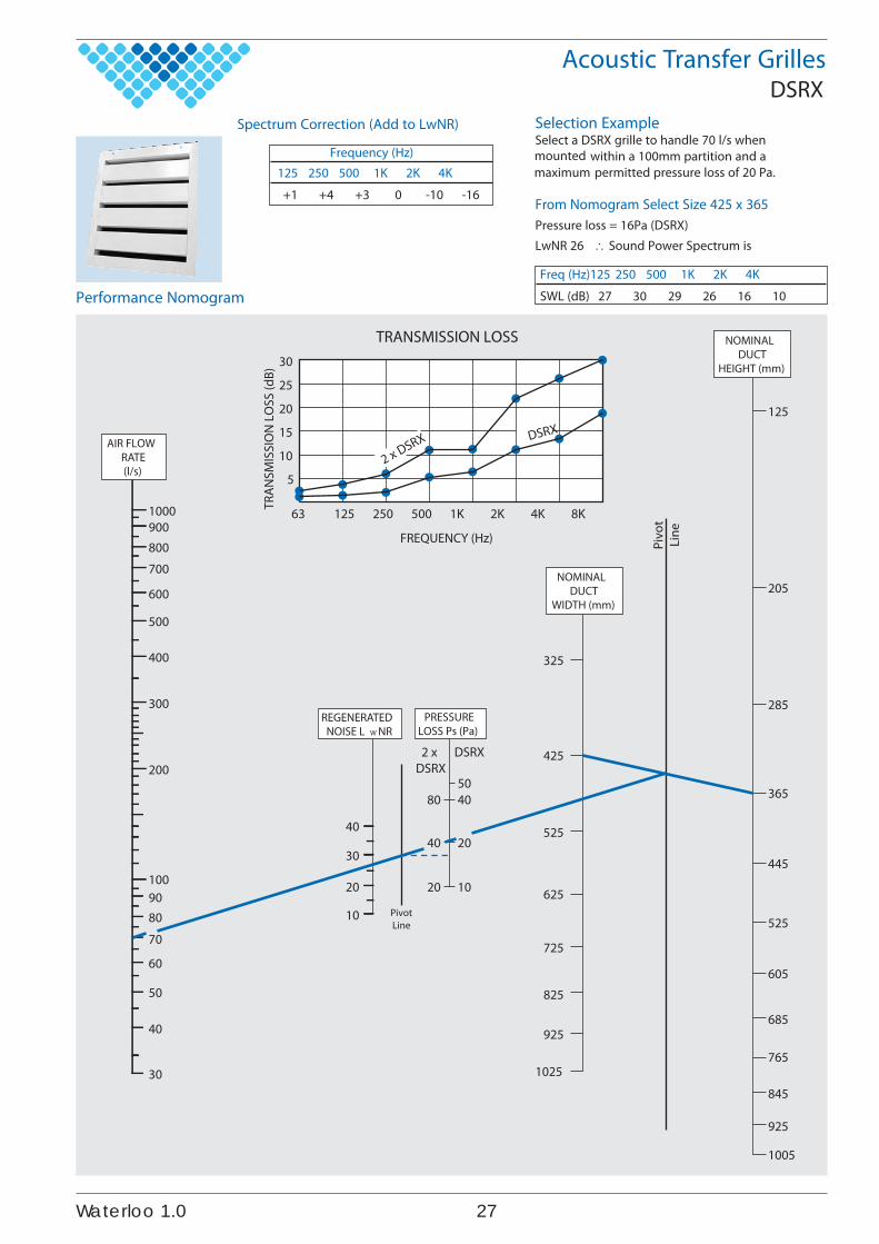
IntroductionThe Waterloo series DSRX have been developed foruse in partitions and doors where a reduction in noisetransfer or “cross-talk” from one space to another isrequired, as well as ventilation air transfer.
The DSRX are manufactured from high qualityaluminium extrusions with channel section coresforming a labyrinth airway lined internally withacoustic damping media. The cores are retainedwithin a flanged frame which is fitted with a sealinggasket. Units are supplied with fixed border andmatching adjustable rear border frame.
DSRX units will only provide acoustic isolationimprovements over that of a clear aperture. DSRX unitsmay be used in series to increase transmission loss.
Product DescriptionDSRX Acoustic transfer grille with rear matching
frame
Features• Suitable for partition, wall or door mounting• Easy to install• Fits most standard doors and partitions• Easy to clean• Modular sizes
FinishesPPM9006 (RAL 9006 Matt Silver)PPM9010 (RAL 9010 Matt White)PPG9010 (RAL 9010 Gloss White)Other colours available on request
SizesWidth 325 minimum to 1025 maximum in 100mmincrements.Height 125 minimum to 1005 maximum in 80mmincrements.
Order Example
DSRX/425/285/PPM9010Nominal widthNominal heightFinish
Nom
inal
W x
H
Nom
inal
W x
H -
25
Nom
inal
W x
H +
51 60
4020
6038
2020
38
75
Variable
4.5
142 Minimum
*
Min40
75
Max100
Door / Partition mounting40 - 100mm thick
* Note: 30mm protrusion with minimum depth of door
DSRX DSRX back-to-back(2 No. required)
Acoustic Transfer GrillesDSRX
1000900800700
600
500
400
300
200
100
325
125
205
285
365
445
525
605
685
765
845
925
1005
425
525
625
725
825
925
1025
9080
70
60
50
40
40
30
20
10
30
4050
20
10
40
20
80
AIR FLOWRATE(l/s)
NOMINALDUCT
HEIGHT (mm)
NOMINALDUCT
WIDTH (mm)
REGENERATEDNOISE L W NR
PRESSURELOSS Ps (Pa)
DSRX2 xDSRX
PivotLine
Pivo
tLi
ne
63
5
10
15
20
25
30
125 250 500 1K 2K 4K 8K
DSRX
2 x DSRX
TRANSMISSION LOSS
FREQUENCY (Hz)
TRAN
SMIS
SIO
N L
OSS
(dB)
Performance NomogramFreq (Hz)125 250 500 1K 2K 4K
SWL (dB) 27 30 29 26 16 10
Frequency (Hz)125 250 500 1K 2K 4K
+1 +4 +3 0 -10 -16
Selection ExampleSelect a DSRX grille to handle 70 l/s when
within a 100mm partition and apermitted pressure loss of 20 Pa.
From Nomogram Select Size 425 x 365Pressure loss = 16Pa (DSRX)LwNR 26 Sound Power Spectrum is
Spectrum Correction (Add to LwNR)
720.1oolretaW
mountedmaximum
Sidewall GrillesWPT
WPT-R
2834
125
150
Nom. W + 25
Nom. W - 25
Order Example
WPT-T/425x125/PPM9010TypeSupply/ExhaustNominal WidthNominal HeightFinish
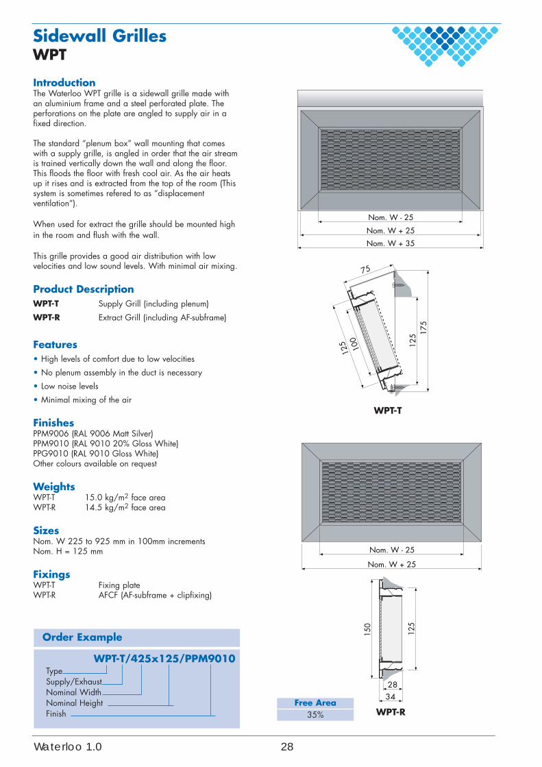
IntroductionThe Waterloo WPT grille is a sidewall grille made withan aluminium frame and a steel perforated plate. Theperforations on the plate are angled to supply air in afixed direction.
The standard “plenum box” wall mounting that comeswith a supply grille, is angled in order that the air streamis trained vertically down the wall and along the floor.This floods the floor with fresh cool air. As the air heatsup it rises and is extracted from the top of the room (Thissystem is sometimes refered to as “displacementventilation”).
When used for extract the grille should be mounted highin the room and flush with the wall.
This grille provides a good air distribution with lowvelocities and low sound levels. With minimal air mixing.
Product DescriptionWPT-T Supply Grill (including plenum)
WPT-R Extract Grill (including AF-subframe)
Features• High levels of comfort due to low velocities
• No plenum assembly in the duct is necessary
• Low noise levels
• Minimal mixing of the air
FinishesPPM9006 (RAL 9006 Matt Silver)PPM9010 (RAL 9010 20% Gloss White)PPG9010 (RAL 9010 Gloss White)Other colours available on request
WeightsWPT-T 15.0 kg/m2 face areaWPT-R 14.5 kg/m2 face area
SizesNom. W 225 to 925 mm in 100mm incrementsNom. H = 125 mm
FixingsWPT-T Fixing plateWPT-R AFCF (AF-subframe + clipfixing)
Free Area35%
WPT-T12
5 175
100
125
75
Nom. W + 25
Nom. W + 35
Nom. W - 25
Waterloo 1.0 28
Sidewall GrillesWPT
Comfort Areavr = .... m/s
Cei
ling
heig
ht
2.4m
I
WPT Supply
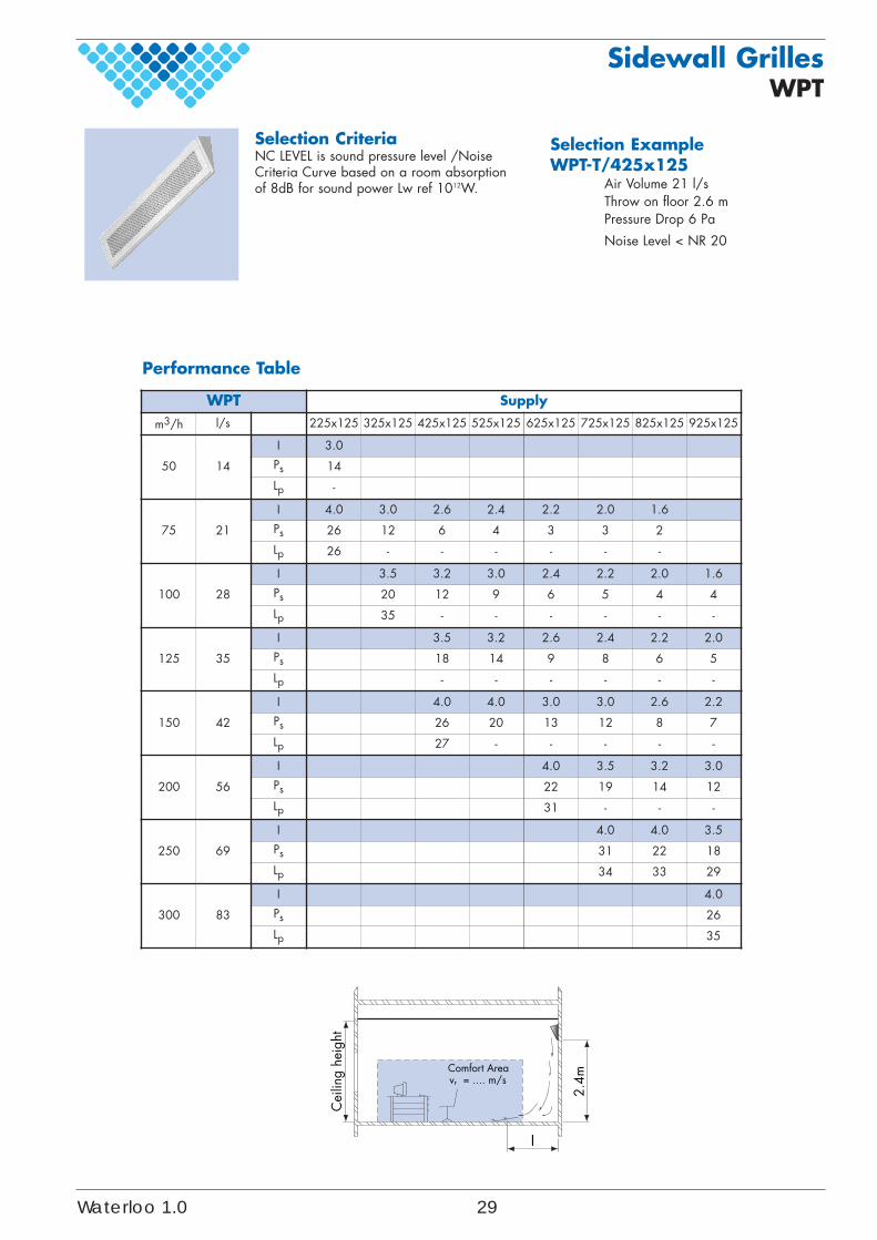
m3/h l/s 225x125 325x125 425x125 525x125 625x125 725x125 825x125 925x125
50 14
I 3.0
Ps 14
Lp -
75 21
I 4.0 3.0 2.6 2.4 2.2 2.0 1.6
Ps 26 12 6 4 3 3 2
Lp 26 - - - - - -
100 28
I 3.5 3.2 3.0 2.4 2.2 2.0 1.6
Ps 20 12 9 6 5 4 4
Lp 35 - - - - - -
125 35
I 3.5 3.2 2.6 2.4 2.2 2.0
Ps 18 14 9 8 6 5
Lp - - - - - -
150 42
I 4.0 4.0 3.0 3.0 2.6 2.2
Ps 26 20 13 12 8 7
Lp 27 - - - - -
200 56
I 4.0 3.5 3.2 3.0
Ps 22 19 14 12
Lp 31 - - -
250 69
I 4.0 4.0 3.5
Ps 31 22 18
Lp 34 33 29
300 83
I 4.0
Ps 26
Lp 35
Selection CriteriaNC LEVEL is sound pressure level /NoiseCriteria Curve based on a room absorptionof 8dB for sound power Lw ref 1012W.
Selection Example WPT-T/425x125
Air Volume 21 l/sThrow on floor 2.6 m Pressure Drop 6 Pa
Noise Level < NR 20
Performance Table
Waterloo 1.0 29
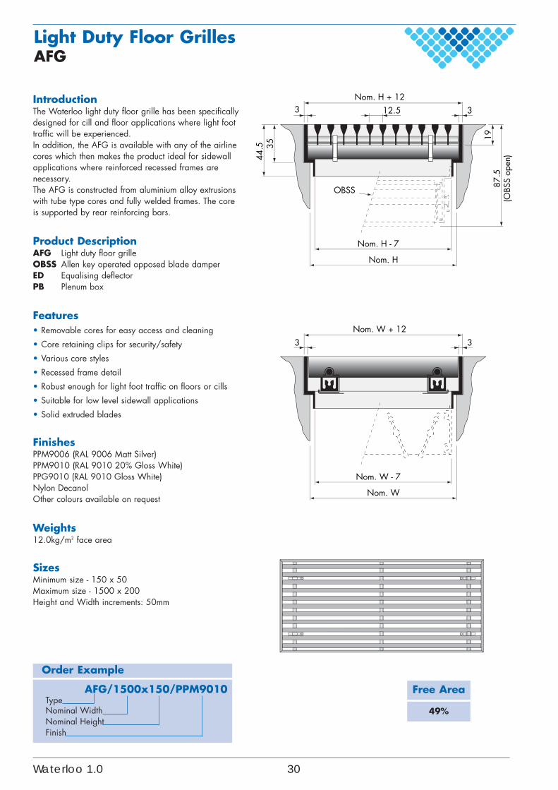
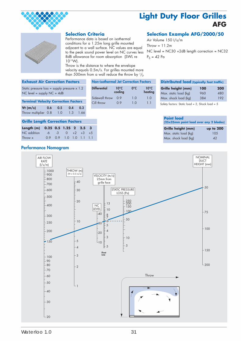
IntroductionThe Waterloo light duty floor grille has been specificallydesigned for cill and floor applications where light foottraffic will be experienced.In addition, the AFG is available with any of the airlinecores which then makes the product ideal for sidewallapplications where reinforced recessed frames arenecessary.The AFG is constructed from aluminium alloy extrusionswith tube type cores and fully welded frames. The coreis supported by rear reinforcing bars.
Product DescriptionAFG Light duty floor grilleOBSS Allen key operated opposed blade damperED Equalising deflectorPB Plenum box
Features• Removable cores for easy access and cleaning
• Core retaining clips for security/safety
• Various core styles
• Recessed frame detail
• Robust enough for light foot traffic on floors or cills
• Suitable for low level sidewall applications
• Solid extruded blades
FinishesPPM9006 (RAL 9006 Matt Silver)PPM9010 (RAL 9010 20% Gloss White)PPG9010 (RAL 9010 Gloss White)Nylon DecanolOther colours available on request
Weights12.0kg/m2 face area
SizesMinimum size - 150 x 50Maximum size - 1500 x 200Height and Width increments: 50mm
Order Example
AFG/1500x150/PPM9010TypeNominal WidthNominal HeightFinish
35
12.5Nom. H + 12
3 3
Nom. W + 123 3
87.5
(OBS
S op
en)44
.5
OBSS
Nom. W
Nom. W - 7
Nom. H
Nom. H - 7
19
Light Duty Floor GrillesAFG
Free Area
49%
Waterloo 1.0 30
Light Duty Floor GrillesAFG
1000900800
700
600
500
400
300
250
200
1009080
70
60
50
40
30
20
150
250200150
10040
30
10
50
10
5
10
5
4
3
2
1
20
40
30
PivotLine
50
75
100
150
200
13
10
8765
4
3
5
20
Throw
AIR FLOWRATE
(l/s/m)
THROW (m)(Vt = 0.5 m/s)
NCLEVEL
VELOCITY (m/s)25mm fromgrille face
STATIC PRESSURELOSS (Pa)
NOMINALDUCT
HEIGHT (mm)
Performance Nomogram
Selection Example AFG/2000/50Air Volume 150 I/s/mThrow = 11.2mNC level = NC30 +2dB length correction = NC32PS = 42 Pa
Selection CriteriaPerformance data is based on isothermalconditions for a 1.25m long grille mountedadjacent to a wall surface. NC values are equalto the peak sound power level on NC curves less8dB allowance for room absorption (SWL re10-12W).Throw is the distance to where the envelopevelocity equals 0.5m/s. For grilles mounted morethan 500mm from a wall reduce the throw by 1/3.
Exhaust Air Correction Factors
Static pressure loss = supply pressure x 1.2NC level = supply NC + 4dB
Grille Length Correction Factors
Length (m) 0.25 0.5 1.25 2 2.5 3NC addition -6 -3 0 +2 +3 +5Throw x 0.9 0.9 1.0 1.0 1.1 1.1
Distributed load (typically foot traffic)
Grille height (mm) 100 200Max. static load (kg) 960 480Max. shock load (kg) 384 192
Point load(25x25mm point load over any 2 blades)
Grille height (mm) up to 200Max. static load (kg) 105Max. shock load (kg) 42
Terminal Velocity Correction Factors
Vt (m/s) 0.6 0.5 0.4 0.3Throw multiplier 0.8 1.0 1.3 1.66
Non-isothermal Jet Correction Factors
Differential 10°C 0°C 10°Ccooling heating
Sidewall throw 0.9 1.0 1.0Cill throw 0.9 1.0 1.1 Safety factors: Static load = 2, Shock load = 5
Waterloo 1.0 31
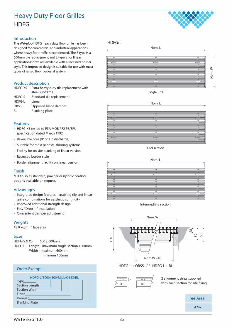
IntroductionThe Waterloo HDFG heavy duty �oor grille has beendesigned for commercial and industrial applicationswhere heavy foot tra�c is experienced. The S type is a600mm tile replacement and L type is for linearapplications; both are available with a recessed borderstyle. This improved design is suitable for use with mosttypes of raised �oor pedestal system.
Product descriptionHDFG-XS Extra heavy duty tile replacement with
steel subframeHDFG-S Standard tile replacementHDFG-L LinearOBSS Opposed blade damperBL Blanking plate
Features• HDFG-XS tested to PSA MOB PF2 PS/SPU
speci�cation dated March 1992
• Reversible core (0° or 15° discharge)
• Suitable for most pedestal �ooring systems
• Facility for on site blanking of linear version
• Recessed border style
• Border alignment facility on linear version
FinishMill �nish as standard, powder or nylonic coatingoptions available on request.
Advantages• Integrated design features - enabling tile and linear
grille combinations for aesthetic continuity• Improved additional strength design• Easy “Drop in” installation• Convenient damper adjustment
Weights18.0 kg/m 2 face area
SizesHDFG-S & XS 600 x 600mmHDFG-L Length - maximum single section 1000mm
Width - maximum 600mmminimum 100mm
Order Example
HDFG-L/1000x300/MILL/OBSS/BLTypeSection LengthSection WidthFinishDamperBlanking Plate
Heavy Duty Floor GrillesHDFG
Free Area
47%
Single unit
End section
Intermediate section
Nom
. W
Nom. LHDFG/L
Nom. L
Nom. L
Nom.W - 40
100
Nom. W
66
2859
HDFG-L + OBSS / / HDFG-L + BL
2 alignment strips supplied with each section for site �xing .
230.1 oolretaW
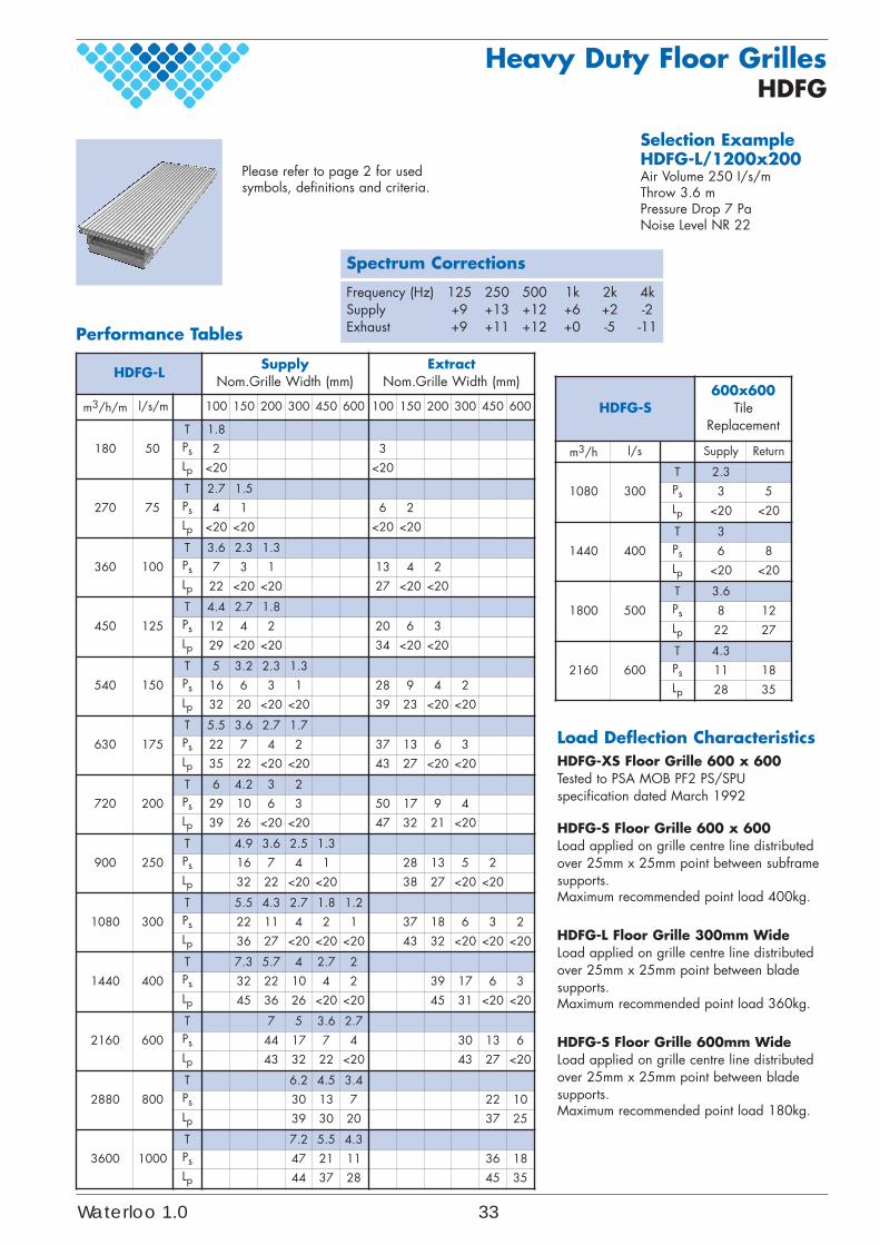
Performance Tables
Load Deflection CharacteristicsHDFG-XS Floor Grille 600 x 600Tested to PSA MOB PF2 PS/SPUspecification dated March 1992
HDFG-S Floor Grille 600 x 600Load applied on grille centre line distributedover 25mm x 25mm point between subframesupports.Maximum recommended point load 400kg.
HDFG-L Floor Grille 300mm WideLoad applied on grille centre line distributedover 25mm x 25mm point between bladesupports.Maximum recommended point load 360kg.
HDFG-S Floor Grille 600mm WideLoad applied on grille centre line distributedover 25mm x 25mm point between bladesupports.Maximum recommended point load 180kg.
Selection Example HDFG-L/1200x200Air Volume 250 I/s/mThrow 3.6 mPressure Drop 7 PaNoise Level NR 22
Spectrum Corrections
Frequency (Hz) 125 250 500 1k 2k 4kSupply +9 +13 +12 +6 +2 -2Exhaust +9 +11 +12 +0 -5 -11
HDFG-LSupply
Nom.Grille Width (mm)Extract
Nom.Grille Width (mm)
m3/h/m l/s/m 100 150 200 300 450 600 100 150 200 300 450 600
180 50
T 1.8Ps 2 3Lp <20 <20
270 75
T 2.7 1.5Ps 4 1 6 2Lp <20 <20 <20 <20
360 100
T 3.6 2.3 1.3Ps 7 3 1 13 4 2Lp 22 <20 <20 27 <20 <20
450 125
T 4.4 2.7 1.8Ps 12 4 2 20 6 3Lp 29 <20 <20 34 <20 <20
540 150
T 5 3.2 2.3 1.3Ps 16 6 3 1 28 9 4 2Lp 32 20 <20 <20 39 23 <20 <20
630 175
T 5.5 3.6 2.7 1.7Ps 22 7 4 2 37 13 6 3Lp 35 22 <20 <20 43 27 <20 <20
720 200
T 6 4.2 3 2Ps 29 10 6 3 50 17 9 4Lp 39 26 <20 <20 47 32 21 <20
900 250
T 4.9 3.6 2.5 1.3Ps 16 7 4 1 28 13 5 2Lp 32 22 <20 <20 38 27 <20 <20
1080 300
T 5.5 4.3 2.7 1.8 1.2Ps 22 11 4 2 1 37 18 6 3 2Lp 36 27 <20 <20 <20 43 32 <20 <20 <20
1440 400
T 7.3 5.7 4 2.7 2Ps 32 22 10 4 2 39 17 6 3Lp 45 36 26 <20 <20 45 31 <20 <20
2160 600
T 7 5 3.6 2.7Ps 44 17 7 4 30 13 6Lp 43 32 22 <20 43 27 <20
2880 800
T 6.2 4.5 3.4Ps 30 13 7 22 10Lp 39 30 20 37 25
3600 1000
T 7.2 5.5 4.3Ps 47 21 11 36 18Lp 44 37 28 45 35
HDFG-S600x600
TileReplacement
m3/h l/s Supply Return
1080 300
T 2.3Ps 3 5Lp <20 <20
1440 400
T 3Ps 6 8Lp <20 <20
1800 500
T 3.6Ps 8 12Lp 22 27
2160 600
T 4.3Ps 11 18Lp 28 35
Please refer to page 2 for usedsymbols, definitions and criteria.
Heavy Duty Floor GrillesHDFG
Waterloo 1.0 33
Order Example
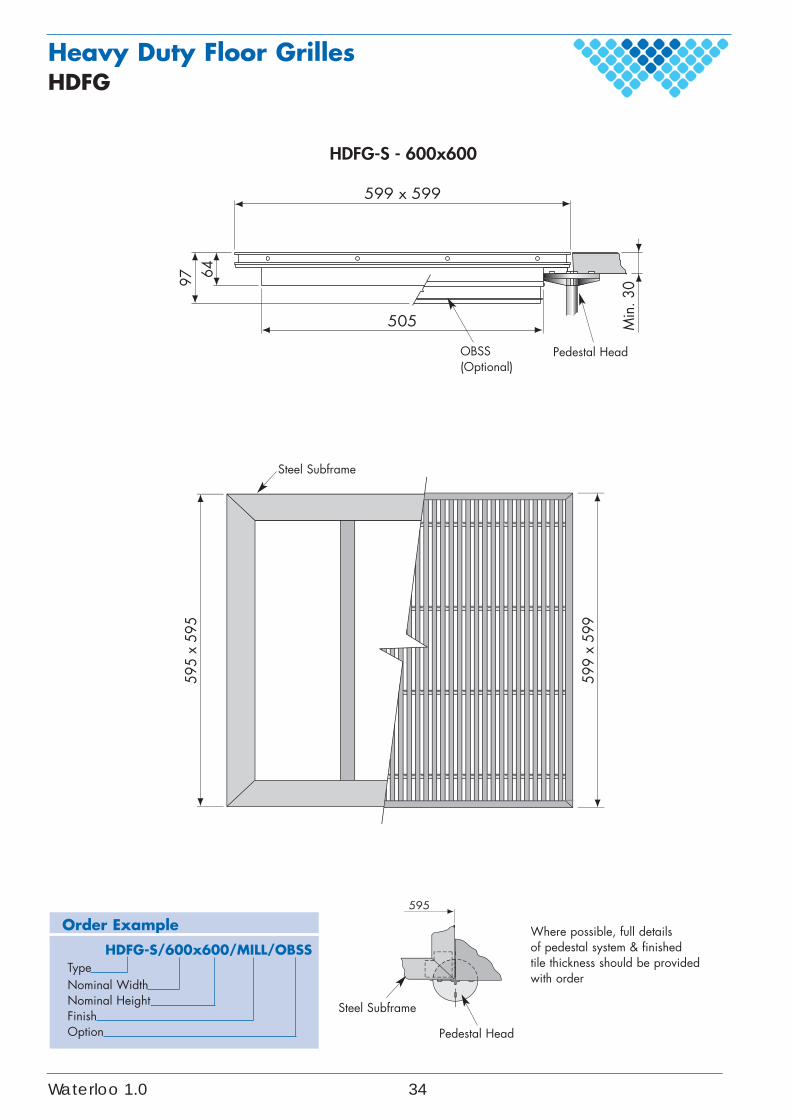
HDFG-S/600x600/MILL/OBSSTypeNominal WidthNominal HeightFinishOption
Heavy Duty Floor GrillesHDFG
Min
. 30
64599 x 599
97
505
HDFG-S - 600x600
595
x 59
5
599
x 59
9
595
Pedestal HeadOBSS(Optional)
Steel Subframe
Pedestal Head
Steel Subframe
Where possible, full detailsof pedestal system & finishedtile thickness should be providedwith order
Waterloo 1.0 34
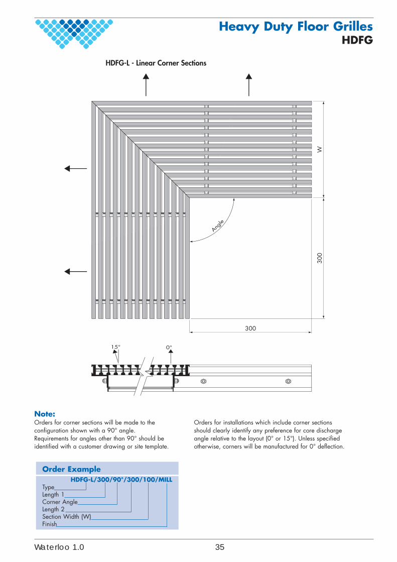
Order ExampleHDFG-L/300/90°/300/100/MILL
TypeLength 1Corner AngleLength 2Section Width (W)Finish
Note:Orders for corner sections will be made to theconfiguration shown with a 90° angle.Requirements for angles other than 90° should beidentified with a customer drawing or site template.
Orders for installations which include corner sectionsshould clearly identify any preference for core dischargeangle relative to the layout (0° or 15°). Unless specifiedotherwise, corners will be manufactured for 0° deflection.
Heavy Duty Floor GrillesHDFG
W300
300
0°15°
Angle
HDFG-L - Linear Corner Sections
Waterloo 1.0 35
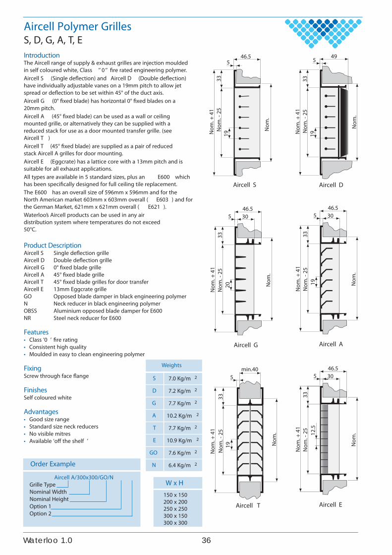
IntroductionThe Aircell range of supply & exhaust grilles are injection mouldedin self coloured white, Class ’’ 0 ’’ fire rated engineering polymer.Aircell S (Single deflection) and Aircell D (Double deflection)have individually adjustable vanes on a 19mm pitch to allow jetspread or deflection to be set within 45° of the duct axis.Aircell G (0° fixed blade) has horizontal 0° fixed blades on a20mm pitch.Aircell A (45° fixed blade) can be used as a wall or ceilingmounted grille, or alternatively they can be supplied with areduced stack for use as a door mounted transfer grille. (seeAircell T )Aircell T (45° fixed blade) are supplied as a pair of reducedstack Aircell A grilles for door mounting.Aircell E (Eggcrate) has a lattice core with a 13mm pitch and issuitable for all exhaust applications.All types are available in 5 standard sizes, plus an E600 whichhas been specifically designed for full ceiling tile replacement.The E600 has an overall size of 596mm x 596mm and for theNorth American market 603mm x 603mm overall ( E603 ) and forthe German Market, 621mm x 621mm overall ( E621 ).Waterloo’s Aircell products can be used in any airdistribution system where temperatures do not exceed50°C.
Product DescriptionAircell S Single deflection grilleAircell D Double deflection grilleAircell G 0° fixed blade grilleAircell A 45° fixed blade grilleAircell T 45° fixed blade grilles for door transferAircell E 13mm Eggcrate grilleGO Opposed blade damper in black engineering polymerN Neck reducer in black engineering polymerOBSS Aluminium opposed blade damper for E600NR Steel neck reducer for E600
Features• Class ‘0 ’ fire rating• Consistent high quality• Moulded in easy to clean engineering polymer
FixingScrew through face flange
FinishesSelf coloured white
Advantages• Good size range• Standard size neck reducers• No visible mitres• Available ‘off the shelf ’
W x H150 x 150200 x 200250 x 250300 x 150300 x 300
Order Example
Aircell A/300x300/GO/NGrille TypeNominal WidthNominal HeightOption 1Option 2
Aircell Polymer GrillesS, D, G, A, T, E
Aircell S
5
Nom
.
46.5
33N
om. +
41
19 Nom
. - 2
5
Aircell D
5
Nom
.
49
33 N
om. +
41
19Nom
. - 2
5
Aircell G
Nom
.
46.530
20
Nom
. + 4
1N
om. -
25
335
Aircell AN
om.
46.530
19
Nom
. + 4
1N
om. -
25
33
5
Aircell T
Nom
.
min.40
19
Nom
. + 4
1N
om. -
25
33
5
Aircell E
Nom
.
46.530
12.5
Nom
. + 4
1N
om. -
25
33
5
Weights
S 7.0 Kg/m 2
D 7.2 Kg/m 2
G 7.7 Kg/m 2
A 10.2 Kg/m 2
T 7.7 Kg/m 2
E 10.9 Kg/m 2
GO 7.6 Kg/m 2
N 6.4 Kg/m 2
630.1oolretaW
Performance Tables
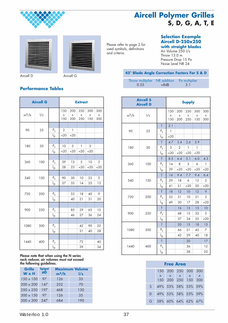
Selection ExampleAircell D-250x250with straight bladesAir Volume 250 I/sThrow 13.0 mPressure Drop 15 PaNoise Level NR 24
Throw multiplier NR addition Pa multiplier0.55 +8dB 3.1
45° Blade Angle Correction Factors For S & DAircell D Aircell G
Please note that when using the N seriesneck reducer, air volumes must not exceedthe following guidelines.
Aircell SAircell D
Supply
m3/h l/s150
x150
200x
200
250x
250
300x
150
300x
300
90 25
T 2.1Ps 1Lp <20
180 50
T 4.7 3.4 2.6 2.9Ps 3 2 1 1Lp <20 <20 <20 <20
360 100
T 8.5 6.4 5.1 6.0 4.3Ps 14 8 3 6 1Lp 29 <20 <20 <20 <20
540 150
T 14 9.4 7.7 9.4 6.4Ps 29 18 6 12 2Lp 41 21 <20 20 <20
720 200
T 18 12 10 12 9Ps 52 31 10 21 3Lp 49 30 17 28 <20
900 250
T 16 13 15 10Ps 48 15 32 5Lp 37 24 35 <20
1080 300
T 20 15 18 13Ps 66 21 45 7Lp 42 29 40 18
1440 400
T 20 17Ps 36 12Lp 38 25
Aircell G Extract
m3/h l/s150
x150
200x
200
250x
250
300x
150
300x
300
90 25 Ps 2 1Lp <20 <20
180 50 Ps 10 3 1 3Lp <20 <20 <20 <20
360 100 Ps 39 13 5 10 2Lp 28 23 <20 <20 <20
540 150 Ps 90 30 10 23 5Lp 37 33 14 25 13
720 200 Ps 53 18 40 9Lp 40 21 31 20
900 250 Ps 85 29 63 15Lp 46 27 36 24
1080 300 Ps 42 90 22Lp 31 40 28
1440 400 Ps 72 40Lp 39 34
Please refer to page 2 forused symbols, definitionsand criteria.
Aircell Polymer GrillesS, D, G, A, T, E
Free Area150
x150
200x
200
250x
250
300x
150
300x
300
S 49% 53% 58% 53% 59%
D 49% 53% 58% 53% 59%
G 58% 60% 64% 62% 67%
GrilleW x H
SpigotØD
Maximum Volumem3/h l/s
150 x 150 97 126 35200 x 200 147 252 70250 x 250 197 468 130300 x 150 97 126 35300 x 300 247 684 190
Waterloo 1.0 37
Performance Tables
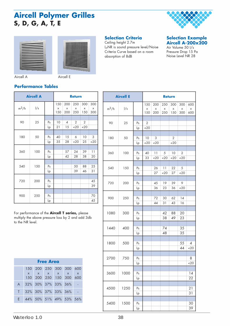
Selection ExampleAircell A-200x200Air Volume 50 I/sPressure Drop 15 PaNoise Level NR 28
Selection CriteriaCeiling height 2.7mLpNR is sound pressure level/NoiseCriteria Curve based on a roomabsorption of 8dB
Aircell A Aircell E
Aircell A Return
m3/h l/s150
x150
200x
200
250x
250
300x
150
300x
300
90 25 Ps 10 4 2 2Lp 21 15 <20 <20
180 50 Ps 40 15 6 10 3Lp 35 28 <20 25 <20
360 100 Ps 57 24 39 11Lp 42 28 38 20
540 150 Ps 50 88 25Lp 39 46 31
720 200 Ps 45Lp 39
900 250 Ps 70Lp 45
Aircell E Return
m3/h l/s150
x150
200x
200
250x
250
300x
150
300x
300
600x
600
90 25 Ps 2Lp <20
180 50 Ps 10 3 2Lp <20 <20 <20
360 100 Ps 40 11 5 10 2Lp 33 <20 <20 <20 <20
540 150 Ps 26 11 22 5Lp 27 <20 27 <20
720 200 Ps 45 19 39 9Lp 36 23 36 <20
900 250 Ps 72 30 62 14Lp 44 31 43 16
1080 300 Ps 42 88 20Lp 38 49 23
1440 400 Ps 74 35Lp 48 35
1800 500 Ps 55 4Lp 44 <20
2700 750 Ps 8Lp <20
3600 1000 Ps 14Lp 22
4500 1250 Ps 21Lp 31
5400 1500 Ps 30Lp 39
For performance of the Aircell T series, pleasemultiply the above pressure loss by 2 and add 3dbto the NR level.
Aircell Polymer GrillesS, D, G, A, T, E
Free Area150
x150
200x
200
250x
250
300x
150
300x
300
600x
600
A 32% 30% 37% 33% 36% -
T 32% 30% 37% 33% 36% -
E 44% 50% 51% 49% 53% 56%
Waterloo 1.0 38
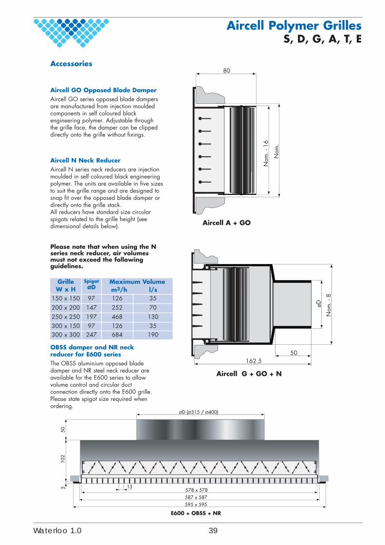
Nom
. - 8
øD
Aircell G + GO + N
162.550
Accessories
Aircell GO Opposed Blade DamperAircell GO series opposed blade dampersare manufactured from injection mouldedcomponents in self coloured blackengineering polymer. Adjustable throughthe grille face, the damper can be clippeddirectly onto the grille without fixings.
Aircell N Neck ReducerAircell N series neck reducers are injectionmoulded in self coloured black engineeringpolymer. The units are available in five sizesto suit the grille range and are designed tosnap fit over the opposed blade damper ordirectly onto the grille stack.All reducers have standard size circularspigots related to the grille height (seedimensional details below).
OBSS damper and NR neckreducer for E600 seriesThe OBSS aluminium opposed bladedamper and NR steel neck reducer areavailable for the E600 series to allowvolume control and circular ductconnection directly onto the E600 grille.Please state spigot size required whenordering.
13578 x 578
ØD (Ø315 / Ø400)
587 x 587
510
250
E600 + OBSS + NR
595 x 595
80
Nom
. - 1
6
Nom
.
Aircell A + GO
Please note that when using the Nseries neck reducer, air volumesmust not exceed the followingguidelines.
Aircell Polymer GrillesS, D, G, A, T, E
GrilleW x H
SpigotØD
Maximum Volumem3/h l/s
150 x 150 97 126 35200 x 200 147 252 70250 x 250 197 468 130300 x 150 97 126 35300 x 300 247 684 190
Waterloo 1.0 39
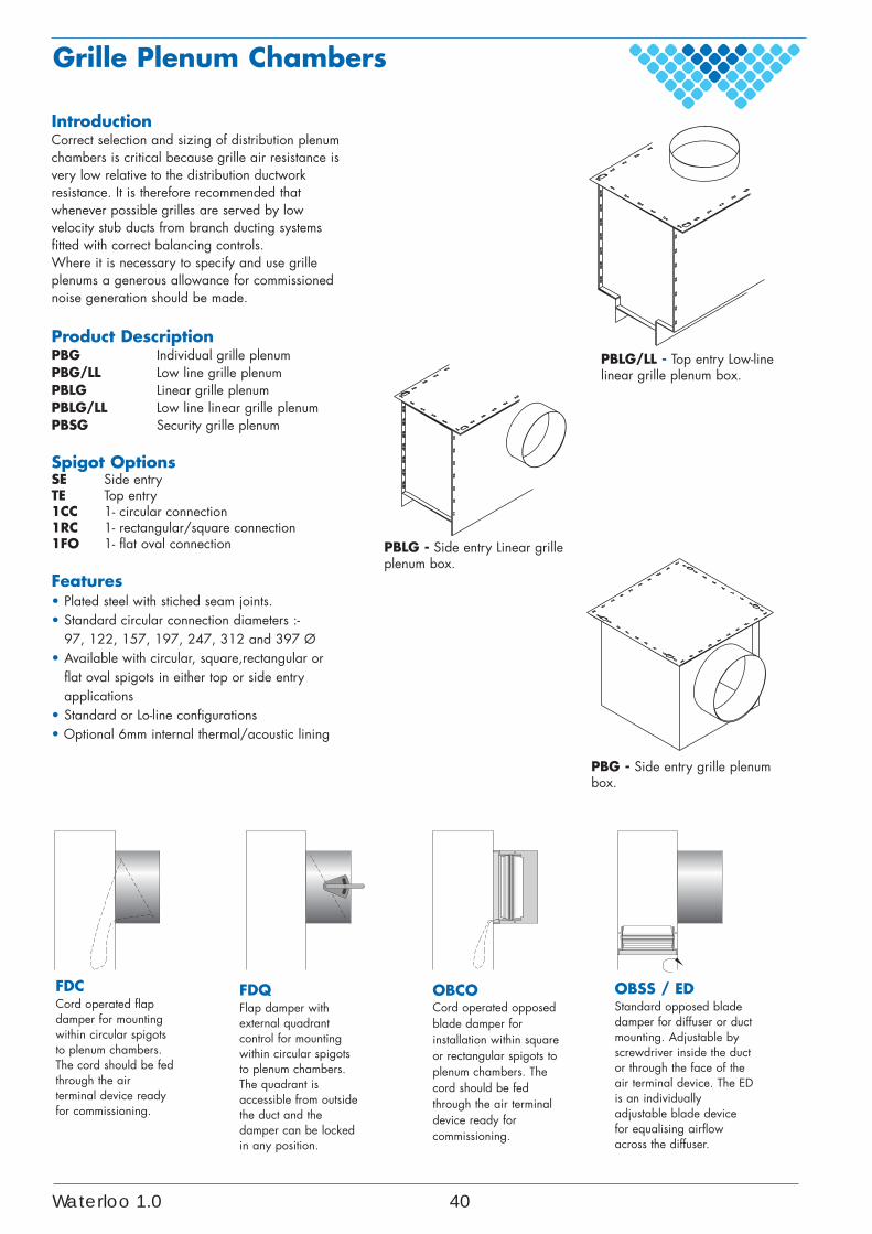
Grille Plenum Chambers
IntroductionCorrect selection and sizing of distribution plenumchambers is critical because grille air resistance isvery low relative to the distribution ductworkresistance. It is therefore recommended thatwhenever possible grilles are served by lowvelocity stub ducts from branch ducting systemsfitted with correct balancing controls.Where it is necessary to specify and use grilleplenums a generous allowance for commissionednoise generation should be made.
Product DescriptionPBG Individual grille plenumPBG/LL Low line grille plenumPBLG Linear grille plenumPBLG/LL Low line linear grille plenumPBSG Security grille plenum
Spigot OptionsSE Side entryTE Top entry1CC 1- circular connection1RC 1- rectangular/square connection1FO 1- flat oval connection
Features• Plated steel with stiched seam joints.• Standard circular connection diameters :-
97, 122, 157, 197, 247, 312 and 397 Ø• Available with circular, square,rectangular or
flat oval spigots in either top or side entryapplications
• Standard or Lo-line configurations• Optional 6mm internal thermal/acoustic lining
PBG - Side entry grille plenumbox.
PBLG - Side entry Linear grilleplenum box.
PBLG/LL - Top entry Low-linelinear grille plenum box.
OBSS / EDStandard opposed bladedamper for diffuser or ductmounting. Adjustable byscrewdriver inside the ductor through the face of theair terminal device. The EDis an individuallyadjustable blade devicefor equalising airflowacross the diffuser.
FDCCord operated flapdamper for mountingwithin circular spigotsto plenum chambers.The cord should be fedthrough the airterminal device readyfor commissioning.
FDQFlap damper withexternal quadrantcontrol for mountingwithin circular spigotsto plenum chambers.The quadrant isaccessible from outsidethe duct and thedamper can be lockedin any position.
OBCOCord operated opposedblade damper forinstallation within squareor rectangular spigots toplenum chambers. Thecord should be fedthrough the air terminaldevice ready forcommissioning.
Waterloo 1.0 40
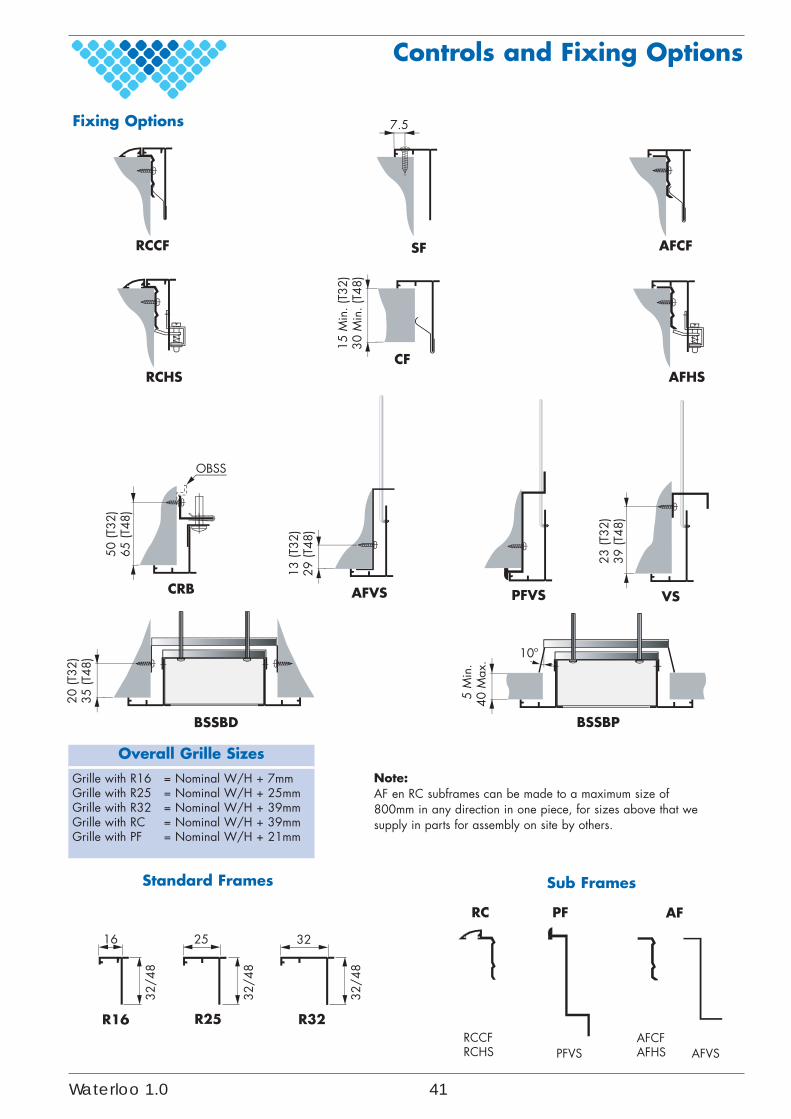
Fixing Options
Overall Grille Sizes
Grille with R16 = Nominal W/H + 7mmGrille with R25 = Nominal W/H + 25mmGrille with R32 = Nominal W/H + 39mmGrille with RC = Nominal W/H + 39mmGrille with PF = Nominal W/H + 21mm
Controls and Fixing Options
Standard Frames Sub Frames
AFVS
13 (T
32)
29 (T
48)
23 (T
32)
39 (T
48)
VSPFVS
7.5
SF
15 M
in. (
T32)
30 M
in. (
T48)
CF
CRB
50 (T
32)
65 (T
48)
OBSS
RCHS AFHS
AFCFRCCF
20 (T
32)
35 (T
48)
BSSBD
5 M
in.
40 M
ax.
BSSBP
10º
16
R16 R25 R32
25 32
32/4
8
32/4
8
32/4
8
RC AFPF
RCCFRCHS
AFCFAFHSPFVS AFVS
Note:AF en RC subframes can be made to a maximum size of800mm in any direction in one piece, for sizes above that wesupply in parts for assembly on site by others.
Waterloo 1.0 41
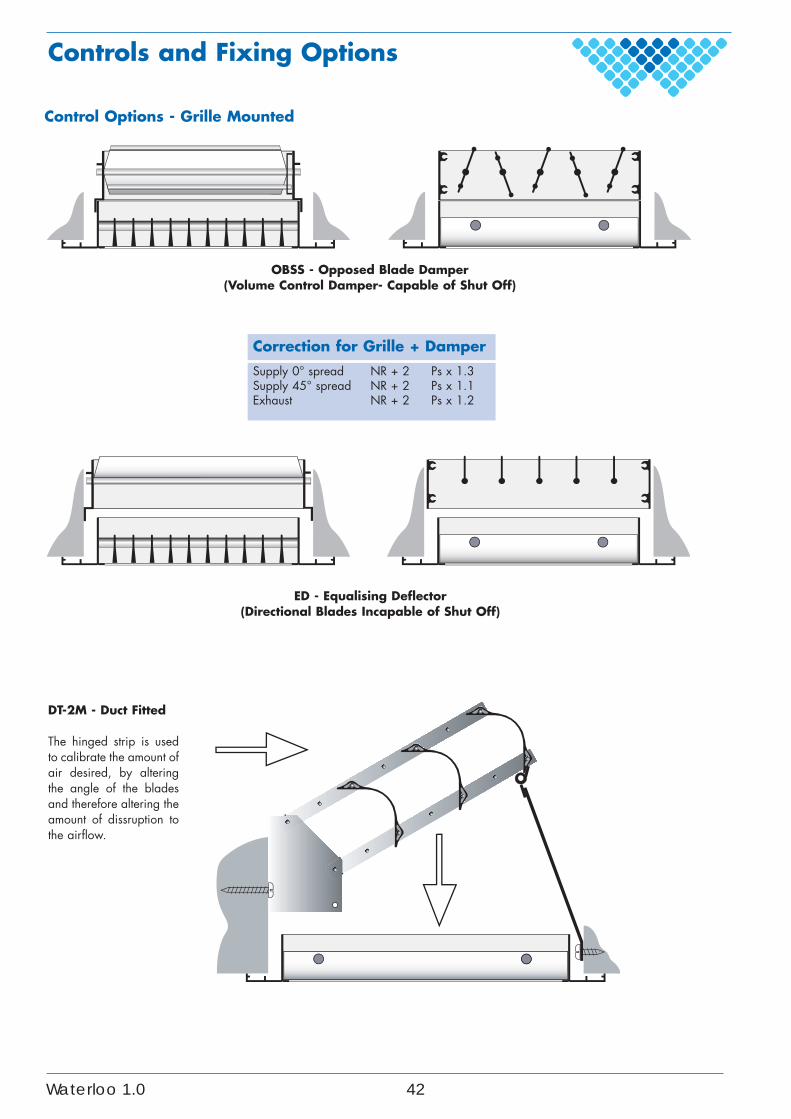
Control Options - Grille Mounted
Correction for Grille + Damper
Supply 0° spread NR + 2 Ps x 1.3Supply 45° spread NR + 2 Ps x 1.1Exhaust NR + 2 Ps x 1.2
OBSS - Opposed Blade Damper(Volume Control Damper- Capable of Shut Off)
DT-2M - Duct Fitted
The hinged strip is usedto calibrate the amount ofair desired, by alteringthe angle of the bladesand therefore altering theamount of dissruption tothe airflow.
Controls and Fixing Options
ED - Equalising Deflector(Directional Blades Incapable of Shut Off)
Waterloo 1.0 42
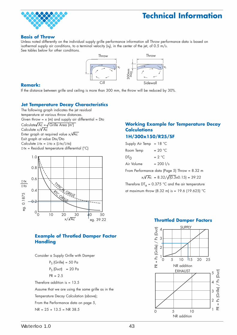
Working Example for Temperature DecayCalculations1H/300x150/R25/SFSupply Air Temp = 18 °C
Room Temp = 20 °C
DT0 = 2 °C
Air Volume = 200 l/s
From Performance data (Page 5) Throw = 8.32 m
= 8.32/ (0.3x0.15) = 39.22
Therefore DTx = 0.375 °C and the air temperature
at maximum throw (8.32 m) is = 19.6 (19.625) °C
x/ Ac
x/ Ac Throttled Damper FactorsSUPPLY
NR addition
NR addition
EXHAUST
4
3
2
1
5
4
3
2
1
0 5 10 15 20 25
0 5 10
PR =
Ps
(Gril
le) /
Ps
(Duc
t)
PR =
Ps
(Gril
le) /
Ps
(Duc
t)
Jet Temperature Decay CharacteristicsThe following graph indicates the jet residualtemperature at various throw distances.Given throw = x (m) and supply air differential = DtoCalculate Ac = Grille Area (m2)Calculate x/ AcEnter graph at required value x/ AcExit graph at value Dtx/DtoCalculate D tx = D to x (D tx/D to)D tx = Residual temperature differential (°C)
TYPICAL GRILLE
RTCGRILLE
1.0
0.8
0.6
0.4
0.2
00 10 20 30 40 50
D txD to
Technical Information
Basis of ThrowUnless noted differently on the individual supply grille performance information all Throw performance data is based onisothermal supply air conditions, to a terminal velocity (vt), in the center of the jet, of 0.5 m/s.See tables below for other conditions.
300m
mm
ax
vrvr
Remark:If the distance between grille and ceiling is more than 300 mm, the throw will be reduced by 30%.
eg. 39.22
eg. 0
.187
5
Example of Throtled Damper FactorHandling
Consider a Supply Grille with Damper
PS (Grille) = 50 Pa
PS (Duct) = 20 Pa
PR = 2.5
Therefore addition is = 13.5
Assume that we are using the same grille as in the
Temperature Decay Calculation (above);
From the Performance data on page 5,
NR = 25 + 13.5 = NR 38.5
Throw Throw
Cill Sidewall
Waterloo 1.0 43


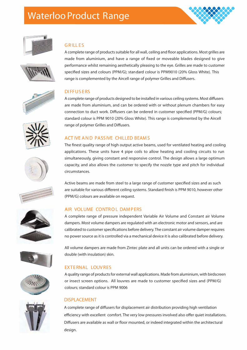
G R ILL E SA complete range of products suitable for all wall, ceiling and applications. Most grilles are
made from aluminium, and have a range of ed or moveable blades designed to give
performance whilst remaining aesthetically pleasing to the eye. Grilles are made to customer
sizes and colours (PPM/G); standard colour is PPM9010 (20% Gloss White). This
range is complemented by the Aircell range of polymer Grilles and Di users.
DI FFUS E RSA complete range of products designed to be installed in various ceiling systems. Most di users
are made from aluminium, and can be ordered with or without plenum chambers for easy
connection to duct work. Di users can be ordered in customer (PPM/G) colours;
standard colour is PPM 9010 (20% Gloss White). This range is complemented by the Aircell
range of polymer Grilles and Di users.
ACT IVE A N D PASS IVE CHILLED BEAM SThe quality range of high output active beams, used for ventilated heating and cooling
applications. These units have 4 pipe coils to allow heating and cooling circuits to run
simultaneously, giving constant and responsive control. The design allows a large optimum
capacity, and also allows the customer to specify the nozzle type and pitch for individual
circumstances.
Active beams are made from steel to a large range of customer sizes and as such
are suitable for various di erent ceiling systems. Standard is PPM 9010, however other
(PPM/G) colours are available on request.
AIR VOLUME CONTR O L DAM P ERSA complete range of pressure independent Variable Air Volume and Constant air Volume
dampers. Most volume dampers are regulated with an electronic motor and sensors, and are
calibrated to customer before delivery. The constant air volume damper requires
no power source as it is controlled via a mechanical device it is also calibrated before delivery.
All volume dampers are made from Zintec plate and all units can be ordered with a single or
double (with insulation) skin.
EXTE RNAL LOUV RESA quality range of products for external wall applications. Made from aluminium, with birdscreen
or insect screen options. All louvres are made to customer spe ed sizes and (PPM/G)
colours; standard colour is PPM 9006
Waterloo Product Range
DISPLACEMENT
design.

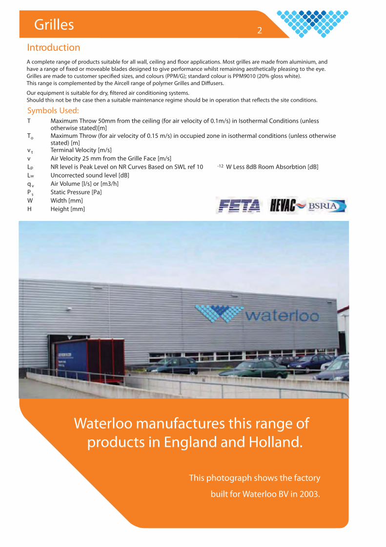
Waterloo Group Limited
Waterloo Air Products plcMills Road, AylesfordMaidstone, Kent ME20 7NBTel: +44 (0)1622 717861Fax: +44 (0)1622 710648email: [email protected]: www.waterloo.co.uk
Waterloo BVPostbus 28, 7450 AA HOLTENOndernemersweg 2, 7451 PK HOLTENTel: +31 (0) 548 374 374Fax: +31 (0) 548 364 165email: [email protected]: www.waterloo.nl
Waterloo KlimatechnikKaiserwerther Straße 115D-40880 RatingenTel: +49 (0) 21 04 - 50 70 86Fax: +49 (0) 21 04 - 50 70 87Mobil: +49 (0) 173 - 2 15 64 59email: [email protected]: www.waterloo-klimatechnik.de
Waterloo AérauliqueLa Grande Arche Paroi NordF-92044 Paris La Défense cedexTel: +33 (0)140 90 30 44Fax: +33 (0)140 90 31 01
internet: www.waterloo-aeraulique.euemail: [email protected]
Hyde Park House, Cartright Street,Newton Hyde. SK14 4EHTel: +44 (0)161 367 1264Fax: +44 (0)161 367 1262email: [email protected]: www.waterloo.co.uk
Waterloo SwitzerlandZugerstrasse 162CH-8820 WädenswilTel: +41 (0) 43 833 20 20Fax: +41 (0) 43 833 20 21
internet: www.waterloo-klimatechnik.chemail: [email protected]
NOVEMBER 2009