Embed Size (px)
Citation preview
[ CARE AND USE MANUAL ]
Waters Advanced Purification Columns 1
CONTENTS
I. INTRODUCTIONa. AP Column Accessories
II. USING THE COLUMN a. Safety and Solvent Considerations
b. Adjusting the Plunger
c. Packing the Column
d. Installing the Column
e. Equilibrating the Column
f. Eliminating Voids
III. CARE AND MAINTENANCEa. Troubleshooting
b. Replacing Ferrules
c. Disassembling and Reassembling the Inlet Connector
d. Replacing End Fittings
e. Replacing Filters and O-rings
f. Storing the Column
IV. SCALING UP SEPARATIONSa. Scaling a Seperation
b. Adjusting Sample Load and Flow Rate
c. Adjusting Gradient Parameters
d. Adjusting Gradient Delay Volume
V. ORDERING INFORMATION
VI. MISCELLANEOUS
WATERS ADVANCED PURIFICATION COLUMNS
I. INTRODUCTION
Waters® Advanced Purification (AP) series of glass columns are
constructed of biocompatible glass and polymeric materials and
can be easily used with silica, polymer, or soft gel packings. To
optimize flow and ensure uniform sample distribution onto the
packed bed, each column incorporates a distributor. A replaceable
filter protects the packing from large particulate contaminants.
Empty AP glass columns are available in a variety of sizes and
utilize the same design to ensure predictable methods transfer
among them. AP glass columns are compatible with both analytical
and preparative HPLC and FPLC systems.
Figure 1: Advanced Purification Column
Outlet tubing
Outlet filter
Outlet connectorassembly
Glass column
Inlet connector assembly
Inlet tubing
Seal adjustment nut
Inlet filter
Plunger
Inlet cap
Fine adjustment knob
Coarse/fineadjustment slide

[ CARE AND USE MANUAL ]
Waters Advanced Purification Columns 2
a. AP Column Accessories
The following accessories are shipped with the AP column:
• Packing funnel
• End plugs for column storage
• Spare Parts Kit consisting of:
- 1 inlet O-ring
- 1 outlet O-ring
- 1 connector tip O-ring
- 1 packing funnel O-ring
- 2 filter assemblies
- 2 ferrules
- 10 gripper ring tools
- 1 Allen wrench
Table 1: AP Column Specifications
II. USING THE COLUMN
a. Safety and Solvent Considerations
Inherent surface imperfections can weaken glass at high pressures.
Maintain lower pressures to prolong column life. The AP glass
column has an external plastic jacket which acts as a safety shield.
To avoid column hardware damage, never exceed 10 MPa (1500 psi
or 100 atm) inside the column.
High backpressures may damage resin-based packing materials.
Consult your packing material care and use manual for packing
material backpressure limits.
AP column materials are compatible with most solvents used in
HPLC. However:
• Certain solvents, such as acetone or chlorinated hydrocarbons,
may reduce the life expectancy of the O-rings.
• The transparent plastic jacket may weaken if exposed to certain organic
solvents. If the jacket crazes, replace it.
b. Adjusting the Plunger
Range of movement
The packed bed is at maximum volume when the hex at the inlet end
of the plunger is flush with the top of the coarse/fine adjustment
slide. Do not withdraw the plunger further, or too few threads will be
engaged to ensure reliable operation.
The slide must be engaged against the locking hex while the column
is in use to prevent the plunger from unscrewing under pressure.
Figure 2: Column at Maximum Volume
Internal diameter 10 mm
Length (nominal) 100, 200, 300, or 600 mm
Maximum operating pressure 10 MPa (100 Atm, 1500 psi)
Filter size 20 µm
Materials along fluid path: Column Tubing Filter Connectors O-rings
Borosilicate glassTefzel®
PolyethyleneRyton-4® (polyphenylene sulfide resin)Buna-N
Operating temperature 4 °C to 50 °C
Correct Incorrect Incorrect Incorrect
Inlet Hex is Flush with Top of Slide
ThreadsExposed
Locking HexExposed
Inlet HexExposed

[ CARE AND USE MANUAL ]
Waters Advanced Purification Columns 3
Using the coarse/fine adjustment slide
The AP column features a coarse/fine adjustment slide to make
plunger adjustment fast and easy. Make sure the slide is in the down
position (against the fine adjustment knob) before pressurizing the
column, Figure 3 shows:
1. Deactivating the inlet O-ring seal
2. Using the slide for coarse adjustment
3. Using the slide for fine adjustment and locking
The slide must engage the locking hex during operation to
prevent the inlet plunger from unscrewing under pressure.
4. Activating the O-ring seal
Figure 3: Adjusting the Plunger Downward
c. Packing the Column
The Waters AP Column is shipped unpacked. The AP Column is
compatible with all commonly used silica- and resin-based packing
materials. Repack the column when performance deteriorates or
when a new method requires a different packing material.
When you repack an AP Column, empty the column first (see
“Emptying the Column”), then proceed to the correct section for
slurry-packing or dry-packing the column.
Column volumes
When you pack the column, you must calculate the column volume
from the length of the packed bed you will use in your method.
Column volumes are:
Short beds
To pack a column with a shorter bed, replace the outlet connector with
a second inlet connector (see Section V, “Ordering Information”). Inlet
connectors have a 40 mm range of movement, allowing you to reduce
column volume to as little as 3 mL. The minimum bed length for a
100 mm long column with two inlet connectors is 20 mm.
Slurry-packing the column
Amount of packing material required
To determine the amount of packing material required, multiply
the column volume, V (mL), by the bulk density of the packing
material, d (g/ml):
Amount of packing material required = V x d
Determining density
To determine the density of the packing material:
1. Slurry 1 g of packing material in 10 mL of buffer and allow the
material to settle.
2. Note the volume of the settled material
3. Calculate density by dividing the weight of the material by the
settled volume.
Column length Column volume
100 mm 8 to 8 mL
200 mm 13 to 16 mL
300 mm 21 to 24 mL
600 mm 45 to 48 mL
Packing Material Bulk Density of the Packing Material
Waters Protein-Pak™ HR 1.2 g/mL
Waters AccellPlus™ silica-based packing materials
0.5 g/mL
Other packing materials Use procedure below to determine density

[ CARE AND USE MANUAL ]
Waters Advanced Purification Columns 4
Preparing slurry solutions
To make slurry solutions, suspend one part of packing material
in three parts of degassed solution. The packing funnel can hold
40 mL of slurry.
Slurry-packing
To slurry-pack the column (Figure 4):
1. Unscrew the inlet connector from the inlet cap.
2. Screw the packing funnel into the inlet cap.
3. Clamp the column upright to a rigid support. Drain the outlet
tubing to waste.
4. Fill the column with the slurry. If the slurry does not flow into
the column, insert a pipette into the tip of the funnel to break
the surface tension.
5. When all of the packing material is in the column, plug the
outlet tubing.
6. Let the packing material settle. Remove excess solvent from the
top of the bed with a pipette. Do not disturb the bed.
7. Remove the funnel, and reattach the inlet connector.
8. Adjust the inlet connector until the plunger contacts the packed bed.
Ensure that the packed bed does not exceed the nominal
column length.
Figure 4: Slurry-Packing the Column
Dry-Packing the Column
Amount of packing material required
To determine the amount of packing material required, multiply
the column volume, V (mL), by the bulk density of the packing
material, d (g/mL):
Amount of packing material required = V x d
Waters Protein-Pak HR must be slurry-packed (see “Slurry-packing
the column”)
Determining density
To determine the ulk density of the packing material, put 19 g of
packing material into a 10 mL graduated cylinder. Tap the graduated
cylinder on a flat surface until the material is completely settled.
Note the volume and calculate the density.
Dry-packing
To dry-pack the column:
1. Unscrew the fine adjustment knob from the inlet cap.
2. Screw the packing funnel into the inlet cap.
3. Remove the outlet tubing.
4. Holding the column vertically, gradually fill the column with packing
material. While filling, tap the column lightly on a flat surface until the
material settles.
5. Remove the funnel and reattach the inlet connector and the
outlet tubing.
6. Adjust the inlet connector until the inlet plunger contacts the
packed bed.
Ensure that the packed bed does not exceed the nominal
column length.
Packing Material Solution
Ion-exchange chromatography High concentration buffer
Reversed-phase chromatography Methanol
Hydrophobic-interaction chromatography (HIC)
Water or low concentration buffer
Slurry
Funnel
Inlet cap
To waste
Packing Material Bulk Density of Packing Material
Waters AccellPlus silica-based packing materials
0.5 g/mL
Other packing materials Use procedure below to determine density

[ CARE AND USE MANUAL ]
Waters Advanced Purification Columns 5
Emptying the column
To remove packing material from the column:
1. Reverse the direction of flow through the column by connecting the
column outlet to the pump.
2. Remove the inlet connector by unscrewing the fine adjustment knob
from the inlet cap.
3. Screw the packing funnel into the inlet cap. Position a beaker under the
mouth of the funnel.
4. Start flow. Gradually increase the flow until the packed bed begins
to move. Continue flow until all packing material washes out of
the column.
5. Remove the funnel and clean the column. Make sure the threads
are clean.
6. Repack the column (see “Slurry-packing the column”, or “Dry-packing
the column”, for repacking instructions).
d. Installing the Column
The AP Column can be installed in:
• Waters 650 Advanced Protein Purification System
• Waters 625 system
• Pharmacia® FPLC® systems
• Other high performance liquid chromatography (HPLC) systems (refer
to Table 4 for adapters and unions used to connect the AP column to
selected systems)
Refer to the appropriate system user’s guide for specific column instal-
lation information.
Tightening fittings
Finger-tighten plastic fittings. Do not overtighten. Overtightening
may damage the threaded parts of the column. Overtightening does
not improve performance.
End plugs
Save the column end plugs for future column storage.
e. Equilibrating the Column
Before performing a test run, equilibrate the column:
1. Gradually increase the flow in 0.1 mL/min increments until you attain
the desired flow rate.
2. While equilibrating the column, check for voids; if present, gradually
reduce flow to 0 mL/min, Adjust the inlet connector until the void is
eliminated. (If this is unsuccessful, see “Eliminating Voids”).
3. Equilibrate the column with 10 to 20 column volumes of mobile phase,
or as recommended by the manufacturer of the packing material.
f. Eliminating Voids
Voids may develop in the column during normal use. To eliminate voids:
1. Stop flow.
2. Disconnect the inlet column tubing from the system to allow displace-
ment of fluid while adjusting the plunger.
3. Deactivate the O-ring seal by turning the seal adjustment nut
counterclockwise.
4. Move the slide to the fine (down) position and turn it slowly to
eliminate the void.
If the fine adjustment knob is all the way down, back if off a few turns.
Move the slide to the coarse adjustment position and move the plunger
down a short distance. To eliminate the void, return the slide to the fine
adjustment position and turn it slowly.

[ CARE AND USE MANUAL ]
Waters Advanced Purification Columns 6
I I I . CARE AND MAINT ENANC E
a. Troubleshooting
Table 2: Troubleshooting the AP Column
b. Replacing Ferrules
Each of the four tubing connections on the AP column uses a gripper
ring between two washers (to keep the Tefzel tubing from sliding when
the column is under pressure) and a ferrule. This section explains how
to set the gripper ring and replace a ferrule on the AP column.
Installing the Ferrule, gripper ring, and washer assembly
To install a new ferrule, gripper ring, and washer (Figure 5):
1. Slide a washer over the end of the tubing.
2. Place a gripper ring in the depression on the gripper ring tool.
3. Insert the end of the tubing into the gripper ring tool as far as it will
go (see Figure 5). This seats the gripper ring at the proper distance
from the end.
4. Withdraw the tubing from the gripper ring tool and slide another washer
over the end of the tubing.
5. Slide the ferrule over the end of the tubing, flared end first.
Use l/I6-inch o.d., 0.009-inch i.d. Tefzel tubing for all connections.
Figure 5: Using the Gripper Ring Tool
c. Disassembling and Reassembling the Inlet ConnectorTo replace the ferrule at the connection between the inlet connector and
the column, you must first disassemble the inlet connector assembly.
Disassembling the inlet connectorTo disassemble the inlet connector assembly:
1. Deactivate the O-ring by turning the seal adjustment knob.
2. Move the slide to the coarse adjustment position and unscrew
the plunger.
3. Use a screwdriver to remove the O-ring located under the cover.
4. Unscrew the seal adjustment knob, exposing the set screw that holds
the core in the proper orientation. Use the Allen wrench from the Spare
Parts Kit to remove the set screw.
5. Push the core out of the plunger and unscrew the inlet connector tip.
6. Pull out the tubing. Use a single-edge razor to cut the tubing above
the washers. To replace the ferrule, follow the procedure
in “Replacing Ferrules”.
Reassembling the inlet connectorTo reassemble the inlet connector:
1. Insert the end of the tubing and the ferrule into the inlet connector tip.
Then slide the core over the tubing and screw it to the tip. Hand-tighten
the fitting.
2. Slide the plunger over the core and replace the set screw. The plunger
core has three slots and the plastic plunger has two threaded holes.
There is only one perfect match. Position the hex of the inlet connector
tip to align onwe of the slots with one of the threaded holes. If there is no
perfect match, tighten the inlet connector tip a little more.
Symptom Possible Cause Corrective Action
Poor resolution Sample overload Reduce sample amount.
Flow rate too high Reduce flow rate.
Packed bed void Adjust inlet connector to eliminate void.
High backpressure
Plugged filter Replace the filter (see “Replacing Filters and O-rings”).
Leakage into plastic shield or out of inlet connector
Foreign matter on sealing surfaces
Clean surfaces and re-tighten.
O-ring seal is not activated
Turn seal adjustment nut counter-clockwise to active O-ring.
Damaged O-rings Replace O-rings (see “Replacing Filters and O-rings”).
Gripper ring Gripper ring tool
Washer
FerruleWasher

[ CARE AND USE MANUAL ]
Waters Advanced Purification Columns 7
3. Replace the set screw. Do not overtighten the set screw; the plunger
core must slide easily to permit the O-ring seal to form.
4. Reassemble the column.
d. Replacing End Fittings
The end fittings for the AP column are compression screws with
gripper rings, washers, and ferrules.
Making a new compression screw assembly
To make a new compression screw assembly:
1. Use a single-edge razor to make a straight, square cut on the plastic
tubing. Make the cut in front of the compression screw.
2. Slide a compression screw fitting and a washer over the end of
the cut tubing.
3. Place a gripper ring in the top depression of the tool (see Figure 5).
Insert the end of the tubing into the gripper ring tool as for as it will
go. This moves the gripper ring to the proper distance from the end of
the tubing.
4. Remove the tubing from the tool and slide the other washer and ferrule
over the end of the tubing.
5. Insert a union over the end fitting assembly and tighten it to seat the
end-fitting.
e. Replacing Filters and O-rings
The inlet and outlet connector assemblies each contain a filter.
Replace filters periodically, depending on:
• The cleanliness of the sample and solvents
• The type and particle size of the packing material
Distributors for AP filters are inside the filter skirt. Look for the
star-like pattern on the distributor surface to ensure the distributor
has not become dislodged.
The AP column contains three O-rings, one each at the connectors
and one at the filter. The outlet connector O-ring does not normally
need replacement.
Accessing the filters
To access the inlet filter:
1. Deactivate the inlet O-ring by turning the seal adjustment knob
counterclockwise.
2. Slide the inlet connector adjustment to the coarse adjustment position,
and unscrew the plunger from the column.
To access the outlet filter, unscrew the outlet connector from the plastic
shield and remove from the glass column.
Installing the filter
To install on inlet filter:
1. Remove the old filter. Pry off the filter with a fingernail (or by inserting
a blunt flat tool between the filter and shoulder of the connector tip).
2. Install the new filter as follows:
For AP-1 (refer to Figure 6)
Ensure that the Tip O-ring is in place on the connector tip. Snap the
new filter onto the connector tip.
For AP-2 & AP-5 (refer to Figure 7)
The Distributor has grooves on one surface and those grooves must
face the filter as shown in Figure 7. Each distributor has an insert on the
backside which contacts the connector. Should the insert fall out of the
Distributor, for consistency, simply re-install it with the circular marks
facing the Distributor as shown. Please note that acceptable factory
installation of the insert may be such that the circular marks are visible
and facing the connector
For AP-2 Columns, install the Distributor assembly into the Filter and
snap them onto the connector.
For AP-5 Columns, install the Distributor assembly into the connector
and snap the filter onto the connector.
Figure 6: Inlet Connector Tip for AP-1 Column
Filter assembly
Connectoro-ring
Connector(inlet shown)
Tip o-ring

[ CARE AND USE MANUAL ]
Waters Advanced Purification Columns 8
Figure 7: Inlet Connector Tip for AP-2 and AP-5 Columns
Replacing an inlet connector O-ring
To replace the inlet connector O-ring:
1. Deactivate the inlet O-ring by turning the seal adjustment
knob. Remove the inlet connector assembly from the column
by unscrewing the plunger.
2. Use a small blunt tool, such as a push pin, to gently pry up the O-ring so
that you may roll it off the connector with your fingers. Carefully push
a new O-ring onto the connector tip. Be sure to select the proper inlet
connector O-ring.
Do not scratch the O-ring groove. If the groove is scratched, the
column will leak.
3. Return the inlet connector assembly to the column. Reactivate
the O-ring.
Replacing a filter O-ring
This small O-ring is located at the edge of the filter skirt. With the filter off, roll
the O-ring off the connector tip and replace it with a new one.
f. Storing the Column
Storage considerations
Store a packed glass column according to the recommendations of the manu-
facturer of the packing material. Note the following:
• Store the column with end plugs in place to prevent column drying.
• Use bacteriostatic solutions in appropriate concentrations, for example,
0.2% sodium azide or 30% ethanol.
• Remove all salts from the column before adding an organic solvent.
An organic solvent added to a salt can cause precipitation, resulting in
increased backpressure.
• Extended storage in high salt buffers may result in the formation
of microcrystals which can lead to high backpressure. (Dissolve
microcrystals by slowly introducing a low ionic strength buffer).
• Do not allow the mobile phase to freeze. Storage at 4 °C is acceptable.
IV. SCALING UP SEPARAT IONS
a. Scaling a Separation
When scaling an analytical separation to a preparative separation, use the
following isolation approach:
1. Define the objective by determining the:
• Complexity of the sample mixture
• Component to be isolated
• Required quantity
• Degree of purity
• Properties of the components in the mixture
2. Perform crude separations to remove large quantities of extraneous
material or to isolate groups or classes of compounds. Simplify a com-
plex sample through coarse separation techniques, such as liquid-liquid
or solid-liquid extraction, crystallization, or precipitation. Centrifuge or
filter the sample to remove particulates.
3. Develop the separation method. To optimize the separation for com-
pounds of interest, make small-scale injections of the sample mixture,
varying the gradient.
4. Perform a loading study. Make progressively larger injections of the
sample mixture on a small scale column, such as the AP-Minicolumn,
to determine the effect of overload on resolution. This study defines the
amount of sample that can be separated in a column of a given volume.
5. Scale up the separation. Translate the small scale parameters to the
large scale system values. Adjust the:
• Sample load
• Flow rate
• Gradient volume
Filter assembly
Connectoro-ring
Connector(inlet shown)
Distributor
Insert

[ CARE AND USE MANUAL ]
Waters Advanced Purification Columns 9
b. Adjusting Sample Load and Flow Rate
When scaling the separation, use analytical and preparative columns
that are:
• The same length
• Packed with the same particle size material
This section describes three equations to adjust the sample load
and flow rate. Use Equation l to calculate the sample load and
Equation 2 to calculate the flow rate. Alternately, use Equation 3 to
calculate a scale factor, which you may use to obtain the preparative
value. In all three equations, if you use preparative columns and
analytical columns of the same length, both sample mass and flow
rate are proportional to the square of the column cross section.
In the following equations:
p = preparative column
a = analytical column
m = mass injected
I = column length
d = column diameter
F = flow rate
v = column volume
sf = scale factor
t = times in gradient table
Vd = delay volume of the instrument
Equation 1To increase sample load in proportion to the volume of the packed bed:
Equation 2To increase flow rate in proportion to the volume of the packed bed:
Equation 3 To calculate the scale factor:
Multiply the analytical sample mass and/or flow rate by the scale
factor to obtain the preparative value. You should obtain similar reten-
tion times and peak widths for both the analytical and the preparative
column and thus, similar resolution.
c. Adjusting Gradient Parameters
If you have scaled the flow rate in proportion to the column volume, the gradi-
ent time profile should remain constant. However, due to pressure limitations
on the preparative instrument or column, you may have to reduce the flow
and adjust the gradient time table. Use the following formula to
• Keep a constant ratio between the gradient volume and column volume
• Adjust the gradient table
d. Adjusting Gradient Delay Volume
Before the gradient reaches the inlet of the column, there is an isocratic period
caused by the delay volume between the point of mixing of the gradient and
the column inlet. The isocratic period exists until the delay volume is purged.
In small columns, the delay volume results in a longer isocratic period than
in larger preparative columns. To maintain the same separation for analytical
and preparative columns, you must delay the gradient for the preparative
column by the some number of column volumes. Use the following equation
to calculate the additional gradient delay time for the preparative column:
[ CARE AND USE MANUAL ]
Waters Advanced Purification Columns 10
V. ORDERING INFORMAT ION
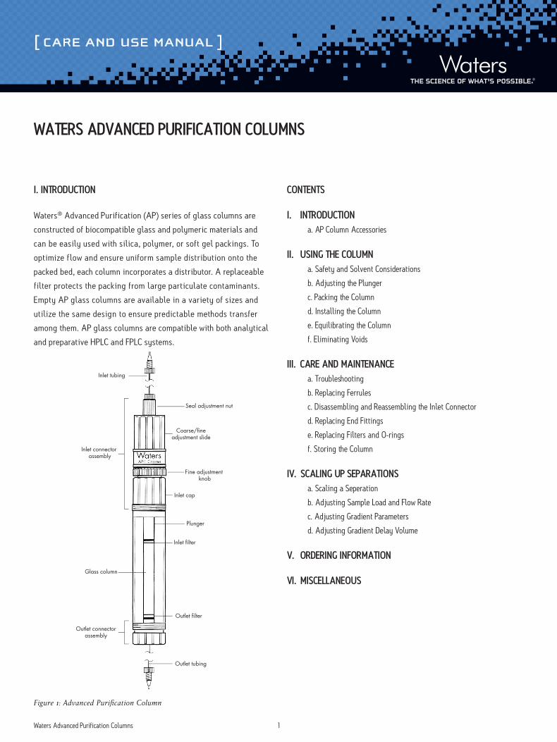
Advanced Purification Glass Columns for Protein Purifications
Waters series of glass columns are constructed of biocompatible glass
and polymeric materials and can be easily used with silica, polymer,
or soft gel packings. To optimize flow and ensure uniform sample
distribution onto the packed bed, each column incorporates a
distributor. A replaceable filter protects the packing from large
particulate contaminants.
Empty AP glass columns are available in a variety of sizes and utilize
the same design to ensure predictable methods transfer among them.
AP glass columns are compatible with both analytical and preparative
HPLC and FPLC systems.
Waters columns feature non-metallic construction and adjustable
bed height with easy-to-use coarse and fine adjustments. The AP
glass columns are available in a variety of dimensions.
Advanced Purification (AP) Glass Cloumn Accessories and Spare Parts
AP Minicolumn Accessories and Spare Parts
AP Column Accessories and Spare Parts
AP-2 Column Accessories and Spare Parts
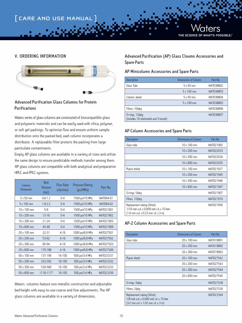
Column Dimension
Bed Volumn
(mL)
Flow Rate (mL/min)
Pressure Rating (psi/MPa)
Part No.
5 x 50 mm 0.8-1.2 0-4 1500 psi/10 MPa WAT064-01
5 x 100 mm 1.8-2.2 0-4 1500 psi/10 MPa WAT064-02
10 x 100 mm 5-8 0-4 1500 psi/10 MPa WAT021901
10 x 200 mm 13-16 0-4 1500 psi/10 MPa WAT021902
10 x 300 mm 21-24 0-4 1500 psi/10 MPa WAT021903
10 x 600 mm 45-48 0-4 1500 psi/10 MPa WAT021906
20 x 100 mm 22-31 4-16 1000 psi/6.8 MPa WAT027501
20 x 200 mm 53-62 4-16 1000 psi/6.8 MPa WAT027502
20 x 300 mm 85-94 4-16 1000 psi/6.8 MPa WAT027503
20 x 600 mm 179-188 4-16 1000 psi/6.8 MPa WAT027506
50 x 100 mm 137-196 16-100 500 psi/3.4 MPa WAT023331
50 x 200 mm 333-392 16-100 500 psi/3.4 MPa WAT023332
50 x 300 mm 530-589 16-100 500 psi/3.4 MPa WAT023333
50 x 600 mm 1118-1177 16-100 500 psi/3.4 MPa WAT023336
Description Dimensions of Column Part No.
Glass Tube 5 x 50 mm WAT038802
5 x 100 mm WAT038803
Column Jacket 5 x 50 mm WAT038804
5 x 100 mm WAT038805
Filters, 10/pkg WAT038806
O-rings, 13/pkg(includes 10 inlet/outlet and 3 funnel)
WAT038807
Description Dimensions of Column Part No.
Glass tube 10 x 100 mm WAT021992
10 x 200 mm WAT022033
10 x 300 mm WAT022034
10 x 600 mm WAT022035
Plastic shield 10 x 100 mm WAT021927
10 x 200 mm WAT021945
10 x 300 mm WAT021946
10 x 600 mm WAT021947
O-rings, 5/pkg WAT021907
Filters, 10/pkg WAT021910
Replacement tubing (Tefzel)1/16 inch o.d. x 0.009 inch i.d. x 10 feet(1.6 mm o.d. x 0.23 mm i.d. x 3 m)
WAT021950
Description Dimensions of Column Part No.
Glass tube 20 x 100 mm WAT019891
20 x 200 mm WAT019892
20 x 300 mm WAT019893
Plastic shield 20 x 100 mm WAT027542
20 x 200 mm WAT027543
20 x 300 mm WAT027544
20 x 600 mm WAT027545
O-rings, 5/pkg WAT027528
Filters, 2/pkg WAT027530
Replacement tubing (Tefzel)1/8 inch o.d. x 0.040 inch i.d. x 10 feet(3.2 mm o.d. x 1.02 mm i.d. x 3 m)
WAT023344

[ CARE AND USE MANUAL ]
Waters Corporation 34 Maple Street Milford, MA 01757 U.S.A. T: 1 508 478 2000 F: 1 508 872 1990 www.waters.com
AP-5 Column Accessories and Spare Parts
Description Dimensions of Column Part No.
Glass Tube 50 x 100 mm WAT019876
50 x 200 mm WAT019877
50 x 300 mm WAT019878
Plastic Shield 50 x 100 mm WAT023370
50 x 200 mm WAT023371
50 x 300 mm WAT023372
50 x 600 mm WAT023373
O-rings, 5/pkg WAT023345
Filter, 2/pkg WAT023343
Replacement tubing (Tefzel)1/8 inch o.d. x 0.040 inch i.d. x 10 feet)(3.2 mm o.d. x 1.02 mm i.d. x 3 m)
WAT023344
©2016 Waters Corporation. Waters and T he Science of What’s Possible are registered trademarks of Waters Corporation. AccellPlus and Protein-Pak are trademarks of Waters Corporation. Tefzel is a registered trademark of E.I. DuPont de Nemours and Company. Pharmacia and FPLC are registered trademarks of Pharmacia LKB. Ryton is a registered trademark of Phillips Chemical Company.
©2016 Waters Corporation. Produced in the U.S.A. July 2016 WAT021938 Rev 6 IH-PDF