Embed Size (px)
Citation preview
-III
...
...
...
,...
",.
...
...
...
-.. ... ... ...
ANGOON WATER'SUPPLY ALTERNATIVES
Alaska Power Authority LI 8RARY COpy
Prepared For.
ALASKA . POWER ,AUTHORITY
By:
IRYLK
&HAYES ENGINEERS I PLANNERS I SURVEYORS
July-1981
TRYCK Head Office / 740 I Street Anchorage, Alaska 99501 /907-279-0543/ Cable TNHANCAK / Telex 090-25332
NYMAN &HAYES ENGINEERS / PLANNERS / SURVEYORS
4354.2
August 20, 1981
Alaska Power Authority 333 W. 4th Avenue - Suite 31 Anchorage, AK 99501
Attn: Brent Petrie, Project Manager
Dear ;·~r. Petrie:
The following report responds to our contract requirements to assess the Favorite Bay Water Supply Alternates.
We believe that even though this is a reconnaissance level study, the information contained herein indicates that a water supply from Favorite Say Creek is technically feasible and compares favorably on an economic basis with other alt~rnatives.
We wish to acknowledge the sUbstantial assistance of Pete Nease, a planner with the Angoon Community Association who originated the idea of a combi~ation hatchery, hydro facility and water supply from Favorite Creek and who has provided substantial assistance to our firm throughout the preparation of this report.
Very truly yours,
. TRYCK, NYMAN & HAYES
?~~/j)~ Frank E. Nyman, P.E. Seni or Partner
lmg Enclosure
I.
II.
III.
IV.
ANGOON WATER SUPPLY ALTERNATIVES
TABLE OF CONTENTS
EXECUTI VE SUf~i'~AR Y. · . . . . . . . . . . . . . . . . . . . . .
INTRODUCTION . . . . . . . . . . . . . . . . . . . . . . . . .
ANGOON WATER & ENERGY SUPPLY REQUIREMENTS.
A. POPULATION . · · · · · · · 8. WATER SUPPLY REQUIREMENTS.
l. Fire F 1 m.". · · · · · · · 2. Domestic Water Supply. · 3 . Fish Processing Water Supply 4. Fish Hatchery Water Supply.
C. ENERGY SUPPLY REQUIREMENTS · SINGLE PURPOSE PROJECT ALTERNATE I . Upgrade Existing Water Supply System
A. INTRODUCTION · · · · · B. EXISTING WATER SUPPLY.
1 • Layout . · · · · · 2. Evaluation. · · · C. DESCRIPTION OF UPGRADED SYSrEM
l. Stromgren Creek. · · · · . · 2. Stromgren Creek and McCarroll
D. CAPITAL COSTS. · · · · · · · . · E. OPERATING AND MAINTENANCE COST
F. PRESENT WORTH SUMMARY. · · · SINGLE PURPOSE PROJECT ALTERNATE II. Favorite Creek Area
A. INTRODUCTION .
B. HYDROLOGY ...
C. INTAKE STRUCTURE .
i
· · · ·
· · · · · · · ·
· · ·
· · · · · · . .
· · · · · · . . . Creek.
· · · ·
· · · · · · · · · . . . . . . . . . . . .
3
6
6
6 5 6 7 8
8
12
12
14 14 18
18 18 23
26
28
29
30
31
32
35
TABLE OF CONTENTS (Can't)
Page
D. PIPELINE ROUTE. · 35
E. EXCAVATION. . · · · · · · · · · 37
F. CONSTRUCTION. 40
G. COST ESTIMATES. 42
H. o & t1 COSTS . · · · · · · · · 44
I. PRESENT WORTH · · · · 45
V. FAVORITE BAY STREAM ~ATER & ENERGY SUPPLY SYSTEM. · · · · · · 46 Multi-Purpose Project
A. INTRODUCTION. · · · · · · · · · · · · · · · · · · 46
B. LOCATION AND LOCAL TOPOGRAPHY • 49
C. HYDROLOGY • . · · · . · · · · · · · · · 50
D. WATER SUPPLY SOURCE 55
E. PRELIMINARY DAM DESIGN CONCEPT. · · · · · · · · · · 56
F. RESERVOIR REGULATION. · 59
G. PENSTOCK AND POWERHOUSE • · · · · · 60
H. ACCESS ROAD AND POWERLINE • 60
I. CAP IT AL COST. · · · · · · · · . · · · · · 64
J. OPERATING AND MAINTENANCE COST. · · · · · · 67
K. PRESENT WORTH SUMMARY 68
L. LAND AND LAND USE . · · · · · · · · · · · S9
VI. CONCLUSIONS AND RECOMMENDATIONS . 70
A. INTRODUCTION .. · · · . 70
B. ALTERNATIVES. · 71
C. RECOMMENDATIONS . 77
i i
TABLE OF CONTENTS (Can't)
VII. POSSIBLE FUNDING SOURCES AND TERMS OF FUNDING.
A. INTRODUCTION
B. WATER SUPPLY
C. FISH HATCHERY.
D. MULTI-PURPOSE PROJECT.
VIII. APPENDICES
iii
Page
79
79
80
81
82
'I
EXECUTIVE SUMMARY
This study consists of an analysis comparing:
1. Upgrading Angoon's existing water system (a single purpose project).
2. Building a new water system in the Favorite Bay Stream area and a pipeline to Angoon (a single purpose project).
3. Utilizing the proposed Favorite gay Hydropo~er/Hatchery project as a source of water and constructing a new pipeline to Angoon (a multi-purpose project).
Each of the proposed projects is designed to provide plentiful, reliable, high
quality water. Estimates of capital costs and operation and maint~nance costs were
completed and the present worth of these costs computed assuming a 50 year life and
a 3% discount rate.
The present worths of the three projects were calculated to be:
-1-
Project
Upgrade existing system
Small Creek Wat~r System (Favorite Bay Stream Area)
Favorite Bay Hydro/Hatchery
PreseDt Worth
$ 3,018,801
3,180,451
2,927,208
The present worth costs of all three alternatives are close enough to be with-
in the estimating error expected at this level of study. Therefore, when examined
strictly on the basis of cost, they are quite comparable. rhe water quality from
the Favorite Bay area, however, is significantly better than that of the source
supplying the existing system. Also, the existing system makes use of a submarine
waterline. It is felt that its elimination would be in the best interests of the
community.
Policies constantly promulgated by professionals in the water works field have
advocated that whenever there is a choice between better and lower quality water
supply sources, the choice should be the higher quality source irrespective of
economic considerations.
-2-
I. INTRODUCTION
The primary objective of this study is to find the optimal solution to
Angoon's water supply problems.
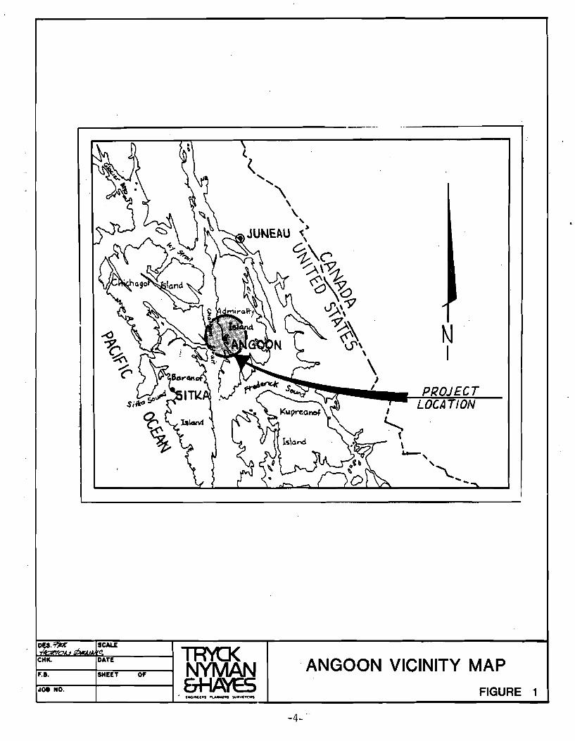
Angoon is a second class city of 527* residents, primarily Native Alaskans.
The community is located in southeast Alaska, approximately 55 miles sout~ of Jlln~au
at the entrance of Kootznahoo Inlet. It has a history of water and energy supply
related problems which appear to be a limiting factor for future development
potential and a major reason for high local unemployment.
The existing water supply comes from an area across Kootznahoo Inlet. Since
most of the source is located in a muskeg lake, drinking water quality is low, and
the system has not been reliable due to a history of accijental disruptions and
corrosion of the submarine waterline.
-3-
,..--------------------
I , ( \ w..-,
N I
''\... .......
SCALE
~CH~K.~~~D~U~E----~ ~ f.B. SHEET 0' ~ . ANGOON VICINITY MAP 0101 NO. CTrlI""\T ~ FIGURE 1
4 .. - -
Several solutions to the community1s water supply problems have be9n proposed
and studied. This study seeks to compare the feasi~i1ity and cost of upgrading
Angoon1s existing water supply with the feasibility and cost of building a new
system. The systems selected for comparison with the existing system are of two
basic types:
1. A single purpose system, i.e. a system that supplies water only.
2. A multi-purpose system, i.e. a system in which one function is supplying water.
The multi-purpose system is the proposed Favorite Bay Hydropower/Hatchery
project, one function of which is to provide Angoon1s public water supply from the
impoundment. The scope of work for the project is included as Appendix A.
-5-
T. ANGOON WATER AND ENERGY SUPPLY REQUIRE~ENTS
A. POPULATION
Limited historical information is available to establish a population gr0wth
trend. Alaskan Natives, mostly Tlingit Indians, do~inate the populatio~ which was
set at 400 by the U.S. Census in 1970; however, local sources estimate the present
Dopulation to be 550. Growth of the area would certainly be affect~d bv the
development under consideration in this study.
B. WATER SUPPLY REQUIREMENTS
1. Fire Flow
Fire fighting water demand rate estimated as per American Insurance Association formula:
G = 1,020 P (1 - 0.01 P) P = PODulation in thousands = 0.6 G = Water demand rate = 780 gpm = 1.73
-6-
Fire fighting water supply storage:
DuratiDn: 4 hrs. Stor3ge Need: (780 x 60 x 4) - 7.48 = 25,026 cft = 187,000 gallons. A primary storage t3nk of approx. 200,000 gallons will b~ sufficient.
Additional reserve storage required:
300,000 gal. = 40,000 cft Total Reserve Storage Needed = 65,187 cft = approx. 500,000 gal.
Anticipated storage in the dam reservoir shouli satisfy additional reserve I
storage requirements. A waterline sized to provide full flow would be required
should a primary storage tank be eliminated.
2. Domestic Water Supply
A relatively high water consumption of 400 gpd/person has been assumed for
the purpose of this study because the Consultant's ext2nsive experience in
Southeastern Alaska indicates running water in winter to prevent freeze-ups creates
a de~and of that magnitude. The construction of buildings in Angoon is similar to
that in communities that experience high water usage.
Total consumption: (400 x 500) = 167 gpm = 0.371 cfs 24 x 60
3. Fish Processing Water Supply
A demand of 0.2 mgd = 140 gpm = 0.31 cfs is estimated. If shrimp
processing should be implemented, a much higher flow would be required. Shrimp
peeling machines normally require approximately 200 gpm per machine.
-7-
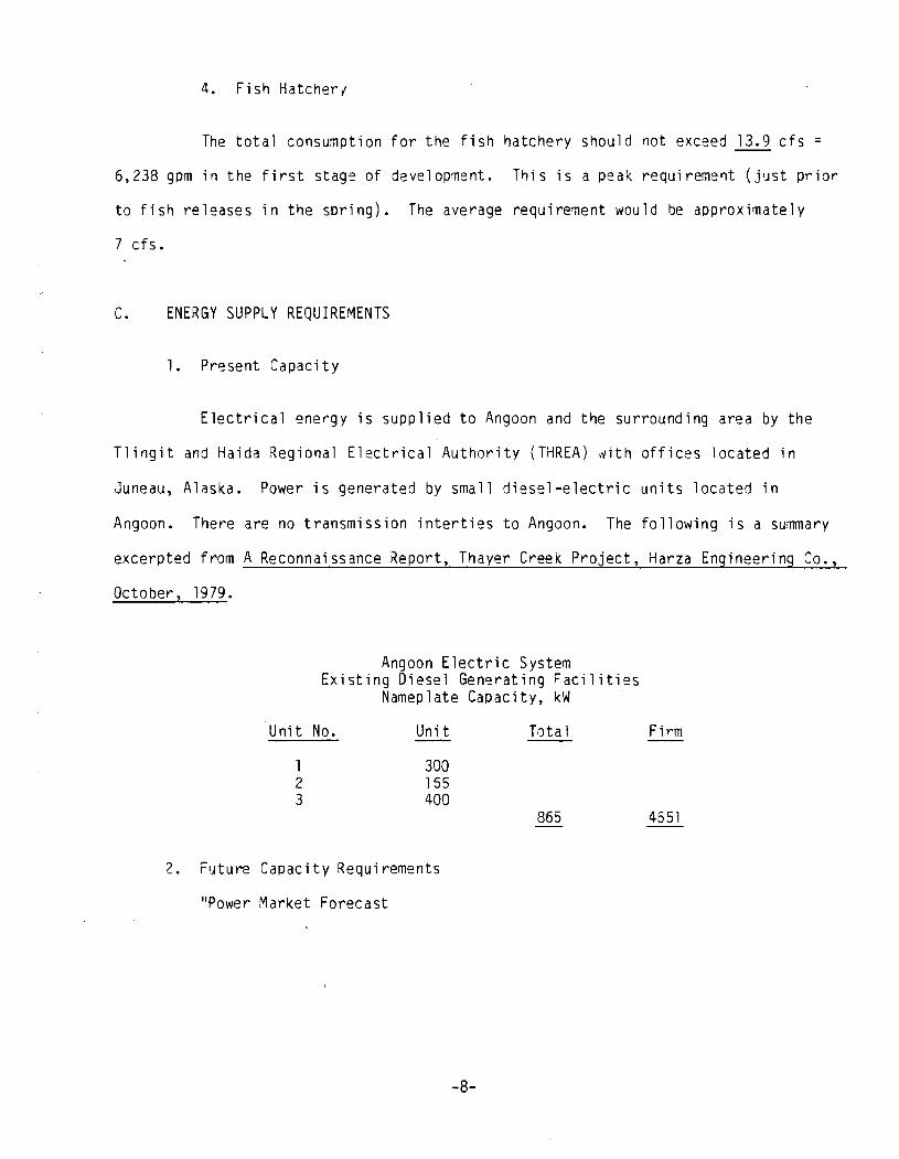
4. Fi sh HatcherY'
The total consumption for the fish hatchery should not exceed 13.9 cfs =
6,238 gpm in the first stag~ of development. This is a peak requireme'1t (j'Jst prior
to fish releases in the spring). The average requirement would be approximately
7 cfs.
C. ENERGY SUPPLY REQUIREMENTS
1. Present Capaci ty
Electrical energy is supplied to Angoon and the surrounding area by the
Tlingit and Haida Regional Electrical Authority (THREA) Nith offices located in
Juneau, Alaska. Power is generated by small diesel-electric units located in
Angoon. There are no transmission interties to Angoon. The following is a summary
excerpted from A Reconnaissance Report, Thayer Creek Project, Harza Engineering Co.,
October, 1979.
Angoon Electric System EXisting Diesel Gen~rating Facilities
Nameplate Capacity, kW
Unit No. Unit Total
1 2 3
300 155 400
865
2. Future Capacity Requirements
"Power Market Forecast
-8-
Firm
4651
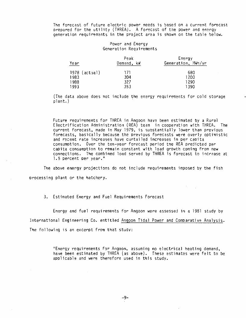
The forecast of future electric Dower needs is based on a current forecast Drepared for the utility (THREA)~ A forecast of the power and en~rgy generation requir~ments in the project area is shown on the table below.
Year
1978 (ac t u a 1 ) 1983 1988 1993
Power and Energy Generation Requirements
Peak Demand, kW
1 71 304 327 353
Energy Generation, MWh/yr
680 1200 1290 l390
(The data above does not include the energy requirements for cold storage plant.)
Future requirements for THREA in Angoon have been estimated by a Rural Electrification A1ministration (REA) team in cooperation with THREA. The current forecast, made in May 1979, is substantially lower than previous forecasts, basically because the previous forecasts were overly opti~istic and r~cent rate increases have curtailed increases in per capita consumption. Over the ten-year forecast period tne REA predicted per capita consumption to remain constant with load-growth coming from new connections. The combined load served by THREA is forecast to increase at 1.5 percent per year."
The above energy projections do not include requirements imposed by the fish
processing plant or the hatchery.
3. Estimated Energy and Fuel Requirements Forecast
Energy and fuel requirements for Angoon were assessed in a 1981 study by
International Engineering Co. entitled Angoon Tidal Power and Comparative Analysis.
The following is an excerpt from that study:
"Energy requirements for Angoon, assuming no electrical heating demand, have been estimated by THREA (as above). These estimates were felt to be applicable and were therefore used in this study.
-9-
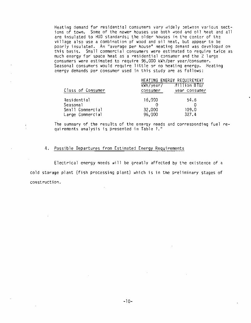
Heating demand for residential consumers vary ~idely bet~een various sections of town. Some of the newer houses use both wood and oil ~eat and all are insulated to HUD standards; the older houses in t1e center of th2 village also use a combination of wood and oil heat, but appear to be poorly insulated. An "average per house" heating demand was developed on this basis. Small commercial consumers were estimated to require twice as much energy for" space heat as a residential CJnsumer and the 2 large consumers were estimated to require 96,000 kWh/per year/consumer. Seasonal consumers would require little or no heating energy. Heating energy demands per consumer used in this study are as follows:
Class of Consumer
Residential Seasonal Sm3.11 Commercial Large Commerci al
HEATING ENERGY REQUIREMENT kWh/year/ Million BTU/ consumer
16,000 o
32,000 96,000
year consumer
54.6 o
109.0 327.4
The summary 0f the results of the energy needs and corresDonding fuel requirements analysis is presented in Table 1."
4. Possible Departures from Estimated Energy Requirements
Electrical energy needs will be greatly affected by the existence Jf a
cold storage plant (fish processing plant) which is in the preliminary stages of
con st ruct i on.
-10-
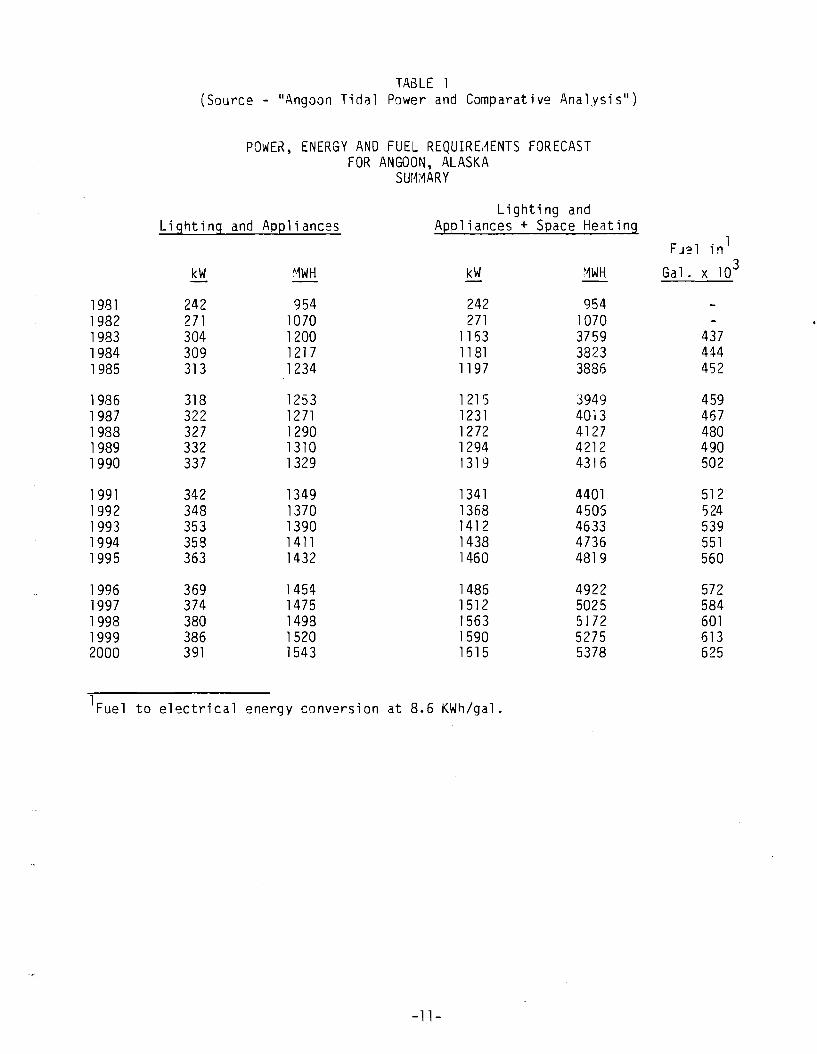
TABLE 1 (Source - "Angoon Tidal Power and Comparative Analysis")
POWER. ENERGY AND FUEL REQUIRE,~ENTS FORECAST FOR ANGOON. ALASKA
Sur~r~ARY
Lighting and Lighting and Apeliances Aepliances + Seace Heating
FIJ~l in l
kW ~1WH kW f~WH Gal. x 103
1981 242 954 242 954 1982 271 1070 271 1070 1983 304 1200 1163 3759 437 1984 309 1217 1181 3823 444 1985 313 1234 1197 3886 452
1986 318 1253 1 21 5 3949 459 1987 322 1271 1231 4013 467 1988 327 1290 1272 4127 480 1989 332 1310 1294 4212 490 1990 337 1329 1319 4316 502
1991 342 1349 1341 4401 512 1992 348 1370 1368 4505 524 1993 353 1390 1412 4633 539 1994 358 1 411 1438 4736 551 1995 363 1432 1460 4819 560
1996 369 1454 1485 4922 572 1997 374 1475 1512 5025 584 1998 380 1498 1563 5172 601 1999 386 1520 1590 5275 613 2000 391 1543 1615 5378 625
lFuel to electrical energy conversion at 8.6 KWh/gal.
-11-
1. INTRODUCTION
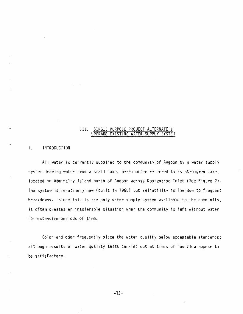
III. SINGLE PURPOSE PROJECT ALTERNATE I UPGRADE EXISTING WATER SUPPLY SYSTEM
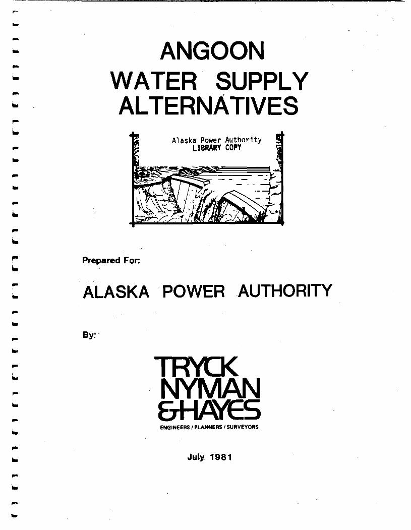
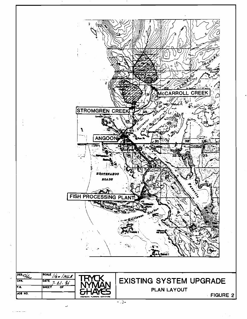
All water is currently supplied to the community of Angoon by a water sUDply
system drawing water from a small lake. hereinafter referred to as Stromgren Lake.
located on Admiralty Island north of Angoon across Kootznahoo Inlet (See Figure 2).
The syste~ is relatively new (built in 1965) but reliability is low due to frequent
breakdowns. Since this is the only water supply system available to the community.
it often creates an intolerable situation when the community is left without water
for extensive periods of time.
Color and odor frequently place the water quality below acceptable standards;
although results of water quality tests carried out at times of low flow appear t~
be satisfactory.
-12-
o "
\
'" . .f'
I::=:~~ __ ~~DA_TE ______ ~ ~ ~8. SMEt arv-u~ 0108 NO.
~. ...... ... ';._. , , ''' ..
EXISTING SYSTEM UPGRADE PLAN LAYOUT
. FIGURE 2 - '.3-
Since the existing water supply system in Angoon does not function
satisfactdri1y, several ways of improving t~e sit~atian have been researched. One
such way is based upon upgrading the existing system. A detailed study of this a1-
ternative is being accomplished at the writing of this report by the USPHS in
Anchorage, who supplied most of the information contained in this chapter. The com-
p1ete USPHS study was not available for use at the time t~is study was finalized,
but from the information available, it appears that.a straight forward improvement 'I
of the existing syste~ is proposed therein. That approach would continue the current
practice of meeting the minimum com~unity requirements for domestic consumption
without making provisions for an industrial supply that would provide 3 basis for
self-sufficiency within the community.
B. EXISTING WATER SUPPLY
1. Layout
The existing water supply facility consists of several non-permanent
structures. This causes frequent disruptions of water supply and since no trained
maintenance workforce is available in Angoon, disruptions are sometimes lengthy in
duration.
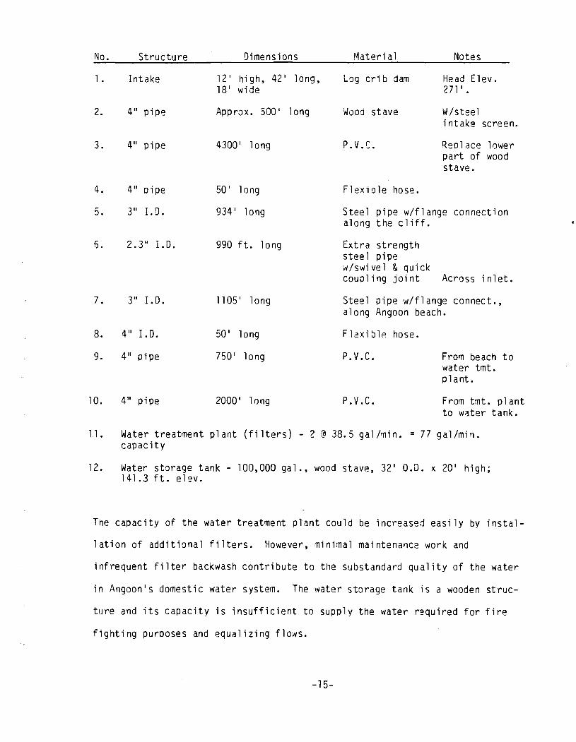
The waters in Stromgren Lake originate in muskeg swamps which affect color and
odor. A 12-foot log crib dam has been erected as an intake structure on the outlet
stream from the lake. Recently two beaver dams appeared on the stream between the
intake structure and the lake. The existing supply line consists of pipes which
differ substantially in material, quality, and slope which makes maintenance
difficult and costly. Numerous complicated "swing" joints in the submarine line
crossing Kootznahoo Inlet cause a significant head loss, requiring boost pumps to
maintain pressure. The following table is an approximate inventory of the existing
supp 1 y system:
-14-
No.
l.
2.
3.
4.
5.
6.
7.
8.
9.
10.
Structure
Intake
4" pipe
4" pipe
4" oipe
3" 1. D.
2.3" 1.0.
3" 1.0.
4" I. D.
4" pipe
4" pipe
Dimensions
12' hi gh, 42' long, 18' wide
Approx. 500' long
4300' long
50' long
934' long
990 ft. long
1105' long
50' long
750' long
2000' long
Material Notes
Log crib dam Head Elev. 271' .
Wood stave W/steel intake screen.
P. V. c. Reolace lower part of wood stave.
Flexible hose.
Steel pipe w/flange connection along the cliff.
Ext ra strength steel pipe w/swivel & quick coupling jOint Across inlet.
Steel pipe w/flange connect., along Angoon beach.
F12xible hose.
P.V.c.
P.V.c.
From beach to water tmt. plant.
From tmt. plant to water tank.
11. Water treatment plant (filters) - 2 @ 38.5 gal/~in. = 77 gal/min. capacity
12. Water storage tank - 100,000 gal., wood stave, 32' 0.0. x 20' high; 141.3 ft. elev.
The capacity of the water treatment plant could be increased easily by instal-
lation of additional filters. However, minimal maintenance work and
infrequent filter backwash contribute to the substandard quality of the water
in Angoon's domestic water system. The water storage tank is a wooden struc-
ture and its capacity is insufficient to supply the water required for fire
fighting purposes and equalizing flows.
-15-
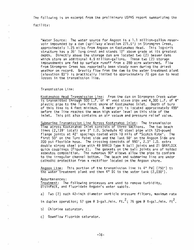
The following is an excerpt from the preliminary USPHS report summarizing the
facility:
"Water Source: The water source for Angoon is a 1.1 million-gallon reservoir impounded by a dam (spillway elevation 271.5 1) on Stromgren Creek, approximately 1.25 miles from Angoon on Kootznahoo Head. This log-crib structure has a 35 1 long crest and stands 121 above grade at its greatest depth. Directly above the storage dam are located two (2) beaver dams which store an additional 4.9 million-gallons. These two (2) storage impoundments are fed by surface runoff from a 280 acre watershed. Flow from Stromgren Creek has reportedly been steady even during the driest weather on record. Gravity flow from the dam to the water treatment plant (elevation 83 1) is practically limited to approximately 70 gpm due to head losses in the transmission line.
Transmission Line:
Kootznahoo Head Transmission Line: From the dam on StrQmgren Creek water is transmitted through 500 L.F. of 411fJood stave pipe and 4,300 L.F. of 411 plastic pipe to the Turn Point shore of Kootznahoo Inlet. Depth of bury of this line is 4 feet minimum. A meter pit is located approximately 480 1 before the line reaches the mean high water level on this side of the inlet. This pit also contains an air vacuum and pressure relief valve.
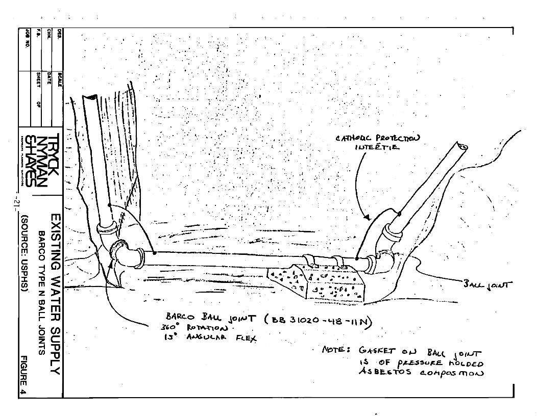
Submarine Transmission Line Across Kootznahoo Inlet: The transmission line across Kootznahoo Inlet consists of three sections. The two beach lines (2,139 1 total) are 311 1.0. Schedule 40 steel pipe with 125-pound flange joints at 421 spacings coated with 10 mils of IIScotch Kate". The first 50 1 on the Turn Point side and the last 50 1 on the Angoon Side are 200 psi flexible hose. The crOSSing consists of 990 1,2.3" 1.0. extra double strong steel pipe with 49 BARCO Type N ball joints and 21 GRAYLOCK quick ~oup1ings (Figure 2). The gaskets on the ball jOints are of molded asbestos composition. The numerous 90 0 elbows allow the pipe to conform to the irregular channel bottom. The beach and submarine line are under cathodic orotection from a rectifier located on the Angoon shore.
Angoon Line: This portion of the transmission line is 4" PVC (750 1) to the water treatment plant and then 411 DI to the water tank (2,030 1).
Appurtenances: Treatment: The following processes are used to remove turbidity, disinfect, and fluoridate Angoonls water supply.
a) Two (2) each 42-inch diameter vertic1e oressure filters, maximum rate
in duplex operation; 57 gpm @ 3-ga1./min. ft.2; 76 gpm @ 4-ga1./min. ft2.
b) Chlorine saturator.
c) Downf1ow fluoride saturator.
-16-
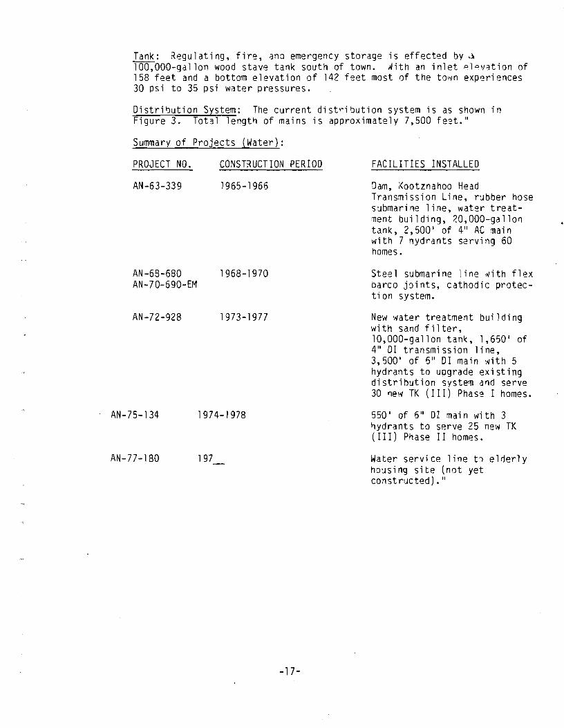
Tank: Regulating, fire, and emergency storage is effected by ~ 100,OOO-gallon wood stave tank south of town. With an inlet plavation of 158 feet and a bottom elevation of 142 feet most of the town experiences 30 psi to 35 psi water pressures.
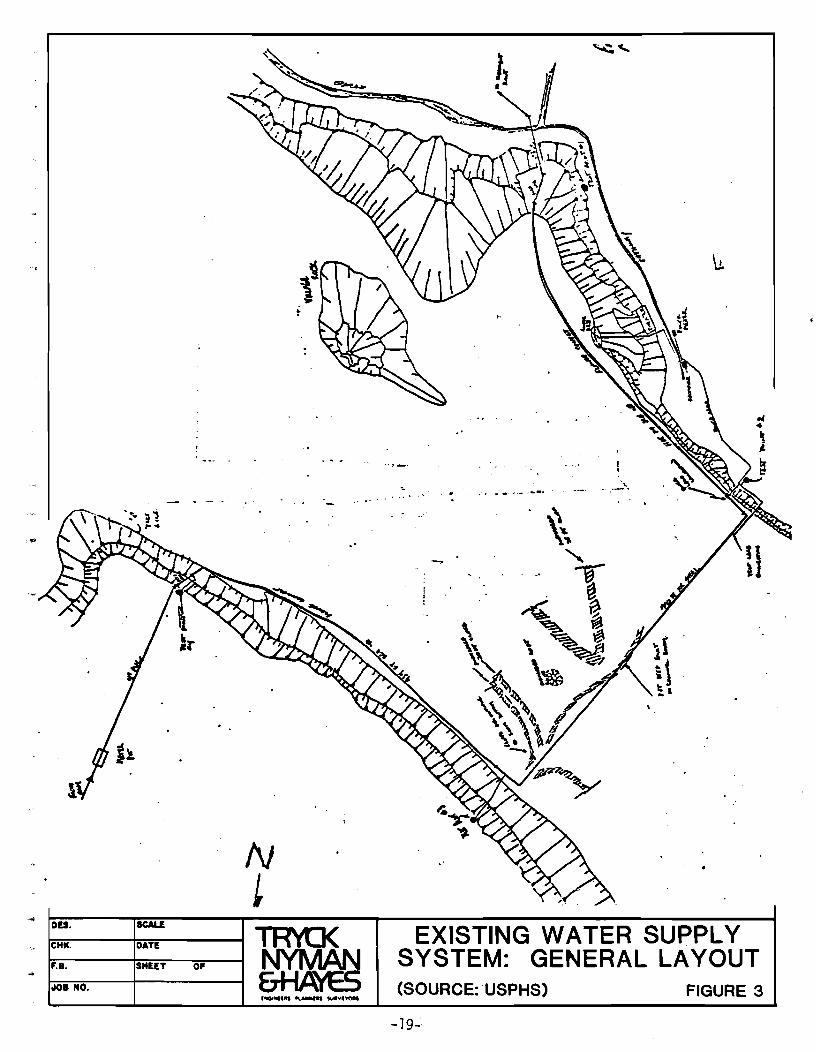
Distribution System: The current distribution system is as shown in Figure 3. Total length of mains is approximately 7,500 fe'?t."
Summary of Projects (Water):
PROJECT NO. CONSTRUCTION PERIOD
AN-63-339 1965-1966
AN-68-680 1968-1970 AN-70-690-EM
AN-72-928 1973-1977
AN-75-134 1974-1978
AN-77-180 197
-17-
FACILITIES INSTALLED
Dam, Kootznahoo Head Transmission Line, rubber hose submarine line, water treatment building, 20,OOO-gallon tank, 2,500 1 of 4" AC main with 7 nydrants serving 60 homes.
Steel submarine line "yith flex barco joints, cathodic protection system.
New water treatment building with sand filter, 10,OOO-gallon tan~, 1,650 1 of 4" 01 transmission line, 3,500 1 of 6" 01 main with 5 hydrants to upgrade existing distribution system and serve 30 new TK (III) Phase I homes.
550 1 of 6" 01 main with 3 hydrants to serve 25 new TK (III) Phase II homes.
Water service line tl elderly housing site (not yet constructed)."
2. Evaluation
Angoon's existing water supply system cannot be characterized as a system
~ith a 50 year lifetime. Some elements of the system have been replaced several
times already. The most frequently disrupted parts of the system appear to be the
waterline on the Angoon beach (due to corrosion) and the submarine line (mainly due
to failures of seals in swivel jOints). The capacity of the system is not adequate
for domestic or industrial requirements.
c. DESCRIPTION OF UPGRADED SYSTEM
1. Stromgren Creek
The existing facility has been evaluated for ways to upgrade it to a 1~ve1
comparable with the other alternates. Several criteria, such as the capability of
the drainage basin to provide sufficient runoff, the quality of the water supplied,
the reliability of the upgraded system and the cost were studied.
a. Hydrology
A detailed study of the hydrology of Admiralty Island has been carried
out by Harza Engineering Company as a part of the Thayer Creek Project
Reconnaissance Report and applicable parts of it are used herein.
Since only one stream gage measurement of Stromgren Creek was available, a
runoff analysis based on the watershed area, the average elevation of the watershed
area and the records of the Hasselborg Creek gaging station was undertaken. The
Hasselborg Creek watershed is described in detail in the hydrology section of the
Harza report. Hassleborg Creek has a runoff of 5.73 cfs per square mile and an
-18-
N t
.... DU. SCALE
~--~~----~~ CHIl. DATE NYMAN f.B. SHEET 0' C"-LJ I\~c:.. 0101 NO. CTrV"\1 ~
, .
. -. ...... .. .,'. - -. ~.- , .. -...
EXISTING WATER SUPPLY SYSTEM: GENERAL LAYOUT (SOURCE: 'USPHS) FIGURE 3
-19":
I N o I
,. z " o· a z
::!!I Ci) ... c'" JJ=-m= (J1C1t ...
'" II:
o '"
<~o \,-, <::) 0
I I III III
ill .i ,. i i I
ICALI • Rn
,. Il1O 100 m , /
()
o
. • ,
'. )... ............. ' .. -- ~~ .......
.-,/ / ." (, ""~ ..... e
(/
PIIOPOUD ITOliut ,& .. ,c
y
I N -' I
i ; ~ ~ z !l
-CJJ o C lJ o m , ,
c CJJ "'tI J: CJJ -.
"T1 G) C lJ m
III %
'" '" ...
0 ...
m > lJ 0 0 -t -< "'tI m z m > r-r-C-0 z -t CJJ
0 • !4 S '"
m X -00 -f -Z G>
:E » -f m JJ OO C "U "U r -<
'-
"
'--."
~ " . - .
., ., ......
.. ' .... ..
, ,:
" .
.....
.i
, .'. ~
'.~ ..... " .
, .... -. . . ..:' .'; .
" :," 0' .. •
:; :.'. "'. '.: ' .. " ': .. :: .. ;' ', .. ";' .. , . .. " ',' ...
.; .:' ;', '0 .. "
..';"'," :"'':. . . ~..., '. '. .. ~. . ...
· :: ~.:.' .. .', ~~" ... ': ~ \
, ~ . . . ,' ','.. ,,,. ,.
" .~: .
4 ~ • . :.
. ',:. '0' " • • .• .. .•.• ; ... 0, . '. ~ ,. ':,' ,' ...
i
" ... \., . . . . :.: ... :;.,
. ; . '" . :.
.', .
. .... ,'. .'
~':: .. . . ... . . .....
• . o. . . ~
~~nc. PRoll.c:,:no.V . '1JTE.e. r. a:.. .
; .
. " .. . . .~ . .. ~ . . .. .
.. ":. ..... - .
.' . .'. 0' :" : ,,' \ ..• ': :.~ . , .. ' .. ~. ," , " '. '" ',' ..
, . .:.: ... :: ~' .... "':J ' · . ~. " · .~. . : t.. •
. ~."
.... : . t. ",
. ~--.--. '. ... --'--.--..... _--
v~ .~:::=~~:;~--.:... . .... :~~_.:~.... .. .:~~,-:.:._: :.
,./ 'J
.--:~ ".-'!'"'
.......
'.
, ' . " .
\
. . ; ''''''- ,
~~~.-------------'-------.---------~----~~--~P--.~,
.-----~---.. -
aA~~o JI\.u.. Jo'~T (~!!a .3102,0 "''''IS -1\ N) ~'OO ~~oAl-13 ~ AU&U(,,~" I=t..E~·
. tV()i£.: ("k$'::~'- O,J BAt.(. ~ 011oJ1
,~ . C!>F f,c..J;;.S,utt:-E. haLOeD A~ 8£..f."TOS 4.0I1Pc\s 111 o A...,)
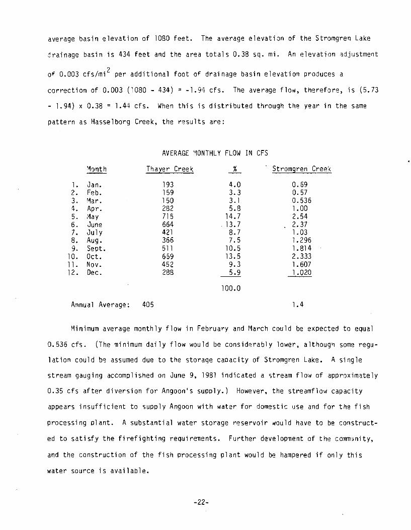
average basin elevation of 1080 feet. The average elevation of the Stromgren Lake
jrainage basin is 434 feet and the area totals 0.38 sq. mi. An elevation adjustment
of 0.003 cfs/mi 2 per additional foot of drainage basin elevation produces a
correction of 0.003 (1080 - 434) = -1.91 cfs. The average flow, therefore, is (5.73
- 1.94) x 0.38 = 1.44 cfs. When this is distributed through the year in the same
pattern as Hasse1borg Creek, the results are:
AVERAGE MONTHLY FLOW IN CFS
Month Thal:er Creek % Stromgren Creek
1. Jan. 193 4.0 0.69 2. Feb. 159 3.3 0.57 3. Mar. 150 3. 1 0.536 4. Apr. 282 5.8 1. 00 5. ,'>1ay 715 14.7 2.54 6. June 664 13.7 2.37 7. July 421 8.7 1. 03 8. Aug. 366 7.5 1.296 9. Sept. 511 10.5 1 .814
10. Oct. 659 13.5 2.333 11. Nov. 452 9.3 1.607 12. Dec. 288 5.9 1 .020
100.0
Annual Average: 405 1.4
Minimum average monthly flow in February and March could be expected to equal
0.536 cfs. (The minimum daily flow would be consid~rably lower, although some regu-
1ation could be assumed due to the storage capacity of Stromgren Lake. A single
stream gauging accomplished on June 9, 1981 indicated a stream flow of approximately
0.35 cfs after diversion for Angoon's supply.) However, the streamflow capacity
appears insufficient to supply Angoon with water for domestic use and for the fish
processing plant. A substantial water storage reservoir would have to be construct-
ed to satisfy the firefighting requirements. Further development of the community,
and the construction of the fish processing plant would be hampered if only this
water source is available.
-22-
For the reasons above, it appears that a simple upgrading of the existing sys-
tem should not be considered because only minimum short ter~ requirements are met.
Long term requirements are not satisfied.
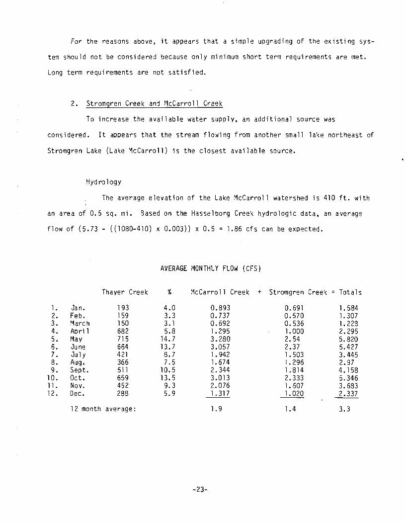
2. Stromgren Creek and McCarroll Creek
To increase the available water supply, an additional source was
considered. It appears that the stream flo'Ning from another small lake northeast of
Stromgren Lake (Lake McCarroll) is the closest available source.
Hyd ro logy
The average elevation of the Lake McCarroll watershed is 410 ft. with
an area of 0.5 sq. mi. Based on the Hasselborg Creek hydrologic data, an average
flow of (5.73 - ((1080-410) x 0.003)) x 0.5 : 1.86 cfs can be expected.
AVERAGE ~ONTHLY FLOW (CFS)
Thayer Creek % McCarroll Creek + Stromgren Creek : Totals
l. Jan. 193 4.0 0.893 0.691 1.584 2. Feb. 159 3.3 0.737 0.570 1.307 3. March 150 3. 1 0.692 0.536 1.228 4. April 682 5.8 1. 295 1.000 2.295 5. May 715 14.7 3.280 2.54 5.820 6. June 664 13.7 3.057 2.37 5.427 7. Ju ly 421 8.7 1 .942 1.503 3.445 8. Aug. 366 7.5 1. 674 1.296 2.97 9. Sept. 511 10.5 2.344 1 .814 4.158
10. Oct. 659 13.5 3.013 2.333 5.346 11. Nov. 452 9.3 2.076 1.607 3.683 12. Dec. 288 5.9 1 .317 1.020 2.337
12 month average: 1.9 1.4 3.3
-23-
~ ="' n 10
~ % != • l" z
~ p
I~
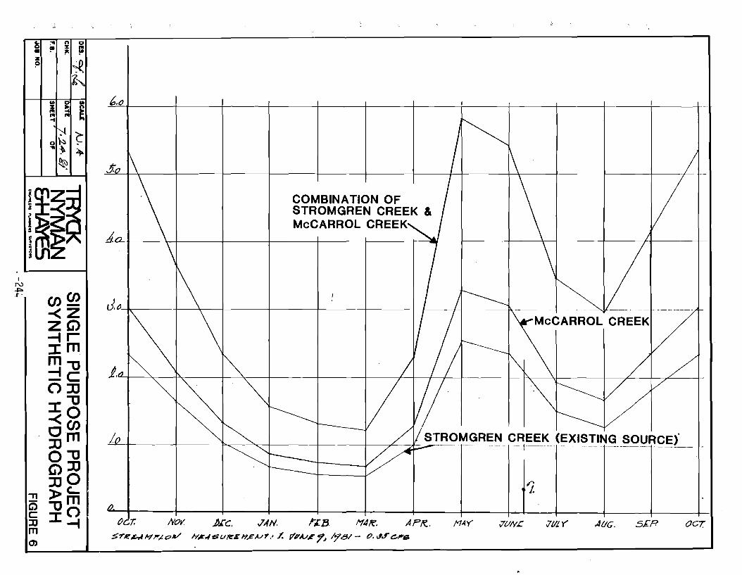
COMBINATION OF STROMGREN CREEK & McCARROL CREEK,
d.na+--~~--~----~--~~--~----~T~~~-+----~--~----~---r/11-------
\ \ J.~,~--+~~~--~--+-I---+---~~~-~
\ ~ ~ J.,J" "" / / 1\ / / ~~.~ V 1/· '\~vvv ~ '" ~t------, ~ I ~~ / STROMGREN CREEK (EXISTING SOURCE)' ~~ ~p--- -------- ---------- ----------------------10
1. /}.
AP/C. n.4Y 7VNL ;Jill y" At/G. 5£.R OCT.
The minimum monthly flow for McCarroll Creek is 0.53 cfs in March and the com
bined minimum average monthly flow of both streams, Stromgren Creek and ~cCarroll
Creek, is 1.23 cfs. This flow could be considered sufficient for supply of water to
Angoon for domestic use, fish processing olant and fire fighting if a large storage
tank (300,000 gal. capacity) is built. However, since the flow of the stream varies
considerably through the month, an approximate one month storage capacity would need
to be constructed on both of the lakes.
Layout
The layout of the existing water supply system from Stromgren and of the
additional new water supply system from McCarroll Creek is shown on Figure No.2.
The most economical solution would be to build an intake structure on
McCarroll Creek at the lake and then follow the 250 ft. contour with the waterline
to the southeast until joining the waterline from Stromgren Creek, then the existing
alignment would be followed. An alternative involving the connection of the two
lakes by a separate waterline has also been considered. However, the complication
created by the terrain and probable requirement for pumping which would then require
a power supply makes this alternative less preferable.
The construction of a new waterline from Angoon to the fish processing plant
is also included in order to provide a comparable evaluation with alternate systems.
-25-
D. CAPITAL COSTS
The consultant's (TNH) experience with waterline systems in Southeast Alaska
indicates that the use of higher quality materials used in the construction of
water supply lines (such as ductile iron) is of substantial economical advantage
compared to other materials because the reduction of maintenance expenses and in
creases in reliability. Also, a line size of not less than 8" should be used to
make orovision for future population development and anticipated industrial
demands. The problems related to durability and frequent maintenance require~ents
of pipe systems of smaller sizes are also a consideration.
-26-
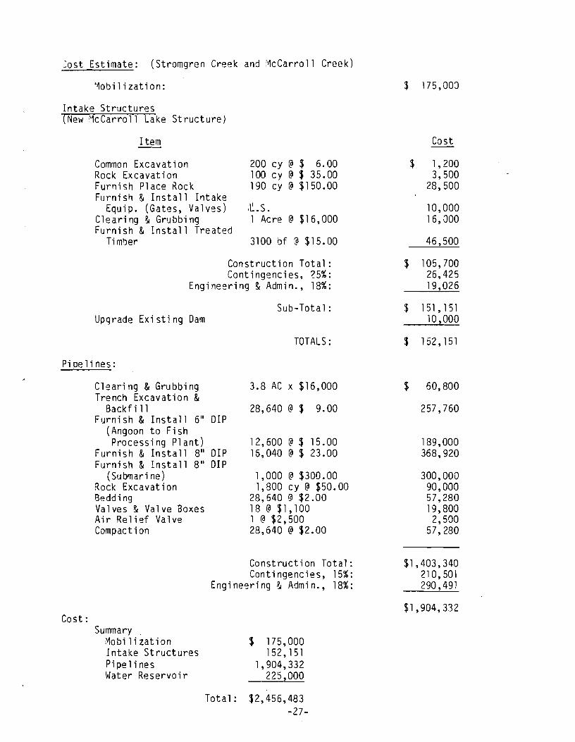
=ost Estimate: (Stromgren Creek and McCarroll Creek)
'~obi1ization:
Intake Structures (New McCarroll Lake Structure)
Item
Common Excavation Rock Excavation Furnish Place Rock Furni sl1 & Install Intake
Equip. (Gates, Valves) Clearing & Grubbing Furnish & Install Treated
Ti ml)er
200 cy @ $ 6.00 1 00 c y @ $ 3 5 . 00 190 cy @ $150.00
It-S. 1 Acre @ $16,000
3100 bf @ $15.00
Construction Total: Contingencies, 25%:
Engineering & Admin., 18%:
Sub-Total: Upgrade Existing Dam
TOTALS:
Pipelines:
Cost:
Clearing & Grubbing Trench Excavation &
Backfill Furnish & Install 6" DIP
(Angoon to Fish Processing Plant)
Furnish & Install 8" DIP Furnish & Install 8" DIP
(Submari ne) Rock Excavation 8edding Valves & Valve Boxes Air Relief Valve Compact ion
3.8 AC x $16,000
28,640 @ $ 9.00
1 2, 600 @ $ 1 5 . 00 15,040 @ $ 23.00
1,000 @ $300.00 1,800 cy @ $50.00
28,640 @ $2.00 18 @ $1, 100 1 @ $2,500 28,640 @ $2.00
Construction Total: Contingencies, 15%:
Engineering & Admin., 18%:
Summary Mobilization Intake Structures Pipelines Water Reservoir
Tota 1 :
$ 175,000 152,151
1,904,332 2?5,OOO
$2,456,483 -27-
$ 175, 000
Cost
$ 1,200 3,500
28,500
10,000 16,000
46,500
$ 105,700 26,425 19,026
$ 151,151 10,000
$ 152,151
$ 60,800
257,760
189,000 368,920
300,000 90,000 57,280 19,800
2,500 57,280
$1,403,340 210,501 290,491
$1,904,332
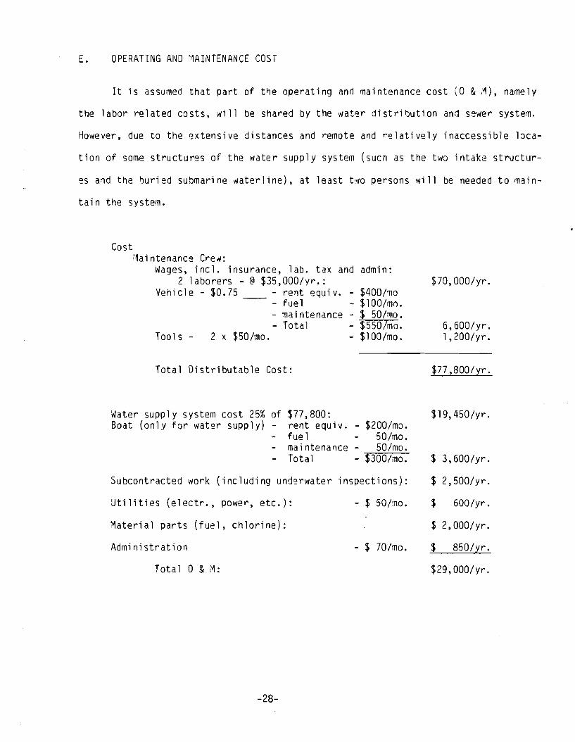
E. OPERATING AND MAINTENANCE COST
It is assumed that part of t~e operating and maintenance cost (0 & ~), namely
the labor related costs, will be shared by the water distribution and sewer system.
However, due to the extensive distances and remote and relatively inaccessible loca-
tion of some structures of the water supply system (suCh as the two intake structur-
es and the ~uried submarine waterline), at least two persons will be needed to main-
tain the system.
Cost Maintenance Crew:
Wages, incl. insurance, lab. tax and 2 laborers - @ $35,000/yr.:
admi n:
Vehicle - $0.75 - rent equiv. -- - fuel
- $400/mo - $lOO/mn.
- maintenance - $ 50/mo. - Total - $550/mo.
Tools - 2 x $SO/mo. - $lOO/mo.
Total Distributable Cost:
Water supply system cost 25% of $77,800: Boat (only for water supply) - rent equiv. - $200/mo.
- fue 1 50/mo. - maintenance - SO/mo.
Total - $300/mo.
Subcontracted work (including underwater inspections):
Utilities (electr., power, etc.): - $ SO/mo.
Material parts (fuel, chlorine):
Administration - $ 70/mo.
Total 0 & I~:
-28-
$lO,OOO/yr.
6,600/yr. 1,200/yr.
$77 ,800/yr.
$19,4S0/yr.
$ 3,600/yr.
$ 2,SOO/yr.
$ 600/yr.
$ 2,000/yr.
$ 850/tr •
$29,000/yr.
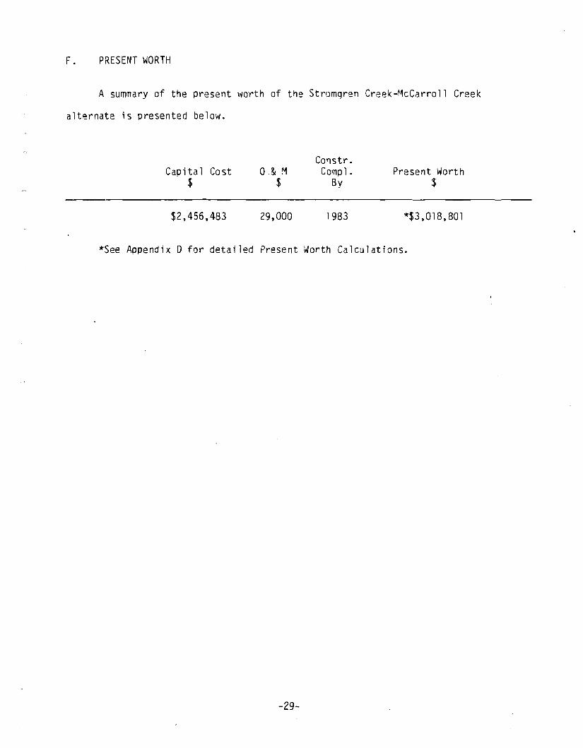
F. PRESENT WORTH
A summary of the present worth of the Stromgren Creek-McCarroll Creek
alternate is presented below.
Capital Cost $
$2,456,483
o & M $
29,000
Constr. Camp 1 . Present Worth
By $
1983 *$3,018,801
*See Appendix D for detailed Present Worth Calculations.
-29-
A. INTRODUCTION
IV. SINGLE PURPOSE ALTERNATE 2 FAVORITE CREEK AREA
A water supply system utilizing water from the Favorite Bay Stream watershed
has been chosen as the single purpose project alternative, comparable to upgrading
the existing system as described in Chapter III.
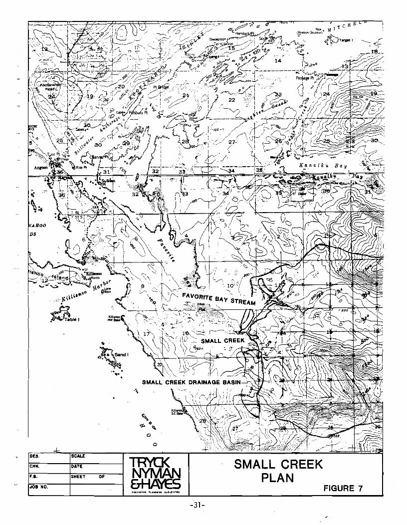
A tributary branch to Favorite Bay Stream (hereinafter ref~rred to as Small
Cre~k), aoproximate1y 0.4 miles upstream from where Favorite Bay Stream discharges
into Favorite Bay (See Figure 7) has been selected as the most promising source of
water for domestic and industrial use in the area. It is proposed that n small
intake structure be built at the 280 feet level on the stream. Water would be
carried to Angoan through a ductile iron pipeline.
-30~
......... --...;. ..... 00
<; J{\\\\I . ~b.1
flo
·t:>~Sandl .. ~~ .. . ..
OF
o
TRYtJ( NYMAN &HA't5
-31-
SMALL CREEK PLAN
FIGURE 7
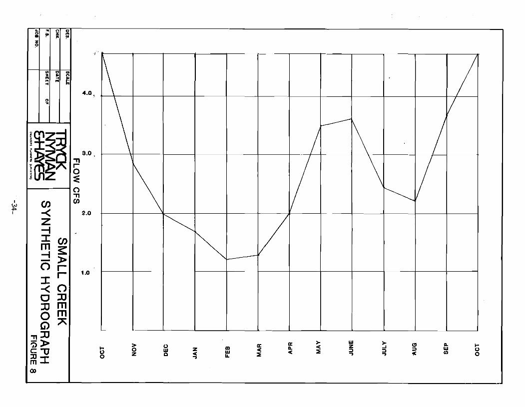
B. HYDROLOGY
A detailed hydrological study of the area of Favorite Bay Creek drainage basin
is presented in Chapter V which deals with the Multi-Purpose Project. Since the
Small Creek watershed is a part of the Favorite Bay Stream watershed, similarities
in runoff characteristics were assumed and thus a synthetic hydrograph was derived
from that used for the ~ulti-Purpose project.
Drainage Basin Characteristics:
Area: Average Elevation:
0.48 mi. 2 960 feet
The basin average elevation for Favorite Bay Stream as a whole has been
calculated to be 985 feet, producing an average annual runoff of 5.45 cfs/mi. 2
Since the average elevation for this subbasin is very nearly equal, the runoff can
also be assumed to be 5.45 cfs/mi. 2• Since the area of the sub-basin is 0.48 . 2 ml. ,
the runoff can be expected to be 2.52 cfs. Since this basin is a subbasin of
Favorite Bay Stream, the flow distribution can be expected to be similar (see
Table 2 and Figure 8).
-32-
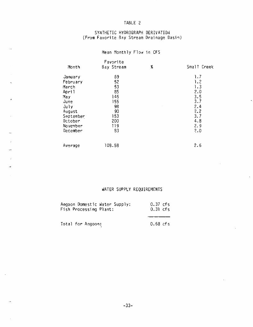
TABLE 2
SYNTHETIC HYDROGRAPH DERIVATION (From Favorite Bay Stream Drainage Basin)
i~ean ~1onthly Flow in CFS
F avori te Month Bay Stream
January 59 February 52 r1arch 53 April 85 May 146 June 155 Ju ly 98 August 90 September 153 October 200 November 119 December 83
Average 108.58
WATER SUPPLY REQUIREMENTS
Angoon Domestic Water Supply: Fish Processing Plant:
Total for Angoon:
-33-
0.37 cfs 0.31 cfs
0.58 cf s
Small Creek
1.7 1.2 1.3 2.0 3.5 3.7 2.4 2.2 3.7 4.8 2.9 2.0
2.6
I w -l==> I
&. 0 • z ?
:"I !II
o ...
~ en -< Z --I
n 0 % '" ~ ~
~
:::t:en m~ :::!» Or :::t: r
-< 0 0 J]
JJ m 0 m Ci) " -n JJ
':i»> c-c ~:::t: Q)
3.0 >
-n r 0 :E 0 -n en
2.0
1.0
1\
... g
\
> o z
~ V ~ ---
o w o
z c ..,
lEI W IL
a: c :IE
a: a. C
/ ----1\ \
w z :) ..,
~
> ..J :) ..,
/
/
a. w en
to o
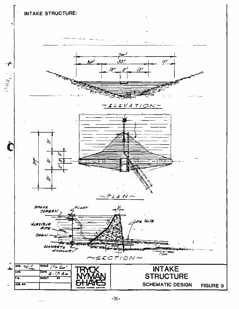
C. INTAKE STRUCTURE
A small intake structure would be constructed approximately at Elevation 280';
a schematic design of such a structure is shown on Figure 9. It is assumed the
structure will be a rockfill dam (or sheet piling) not ~igher than 20' with no sig
nificant storage capacity (100,000 cf). The ~levation of the structure relative to
Angoon will create enough head to satisfy the supply requirements.
D. PIPELINE ROUTES
The water will be conducted from the intake structure to Angoon by gravity
flow through a ductile iron pipeline, equipped with valves spaced approximately
every 2,500'. The pipe will be laid into a trench with no less than 6"'of selected
bedding material under and over the pipe and 12" on each side. Above that will oe
placed not less than 4' of nonclassified backfill material. Part of the backfill
height could be substituted with adequate insulation material if ~xcavation of a
deep trench would be difficult. Also, in the non-traveled forested areas the mini
mum cover can be reduced to 3 ft.
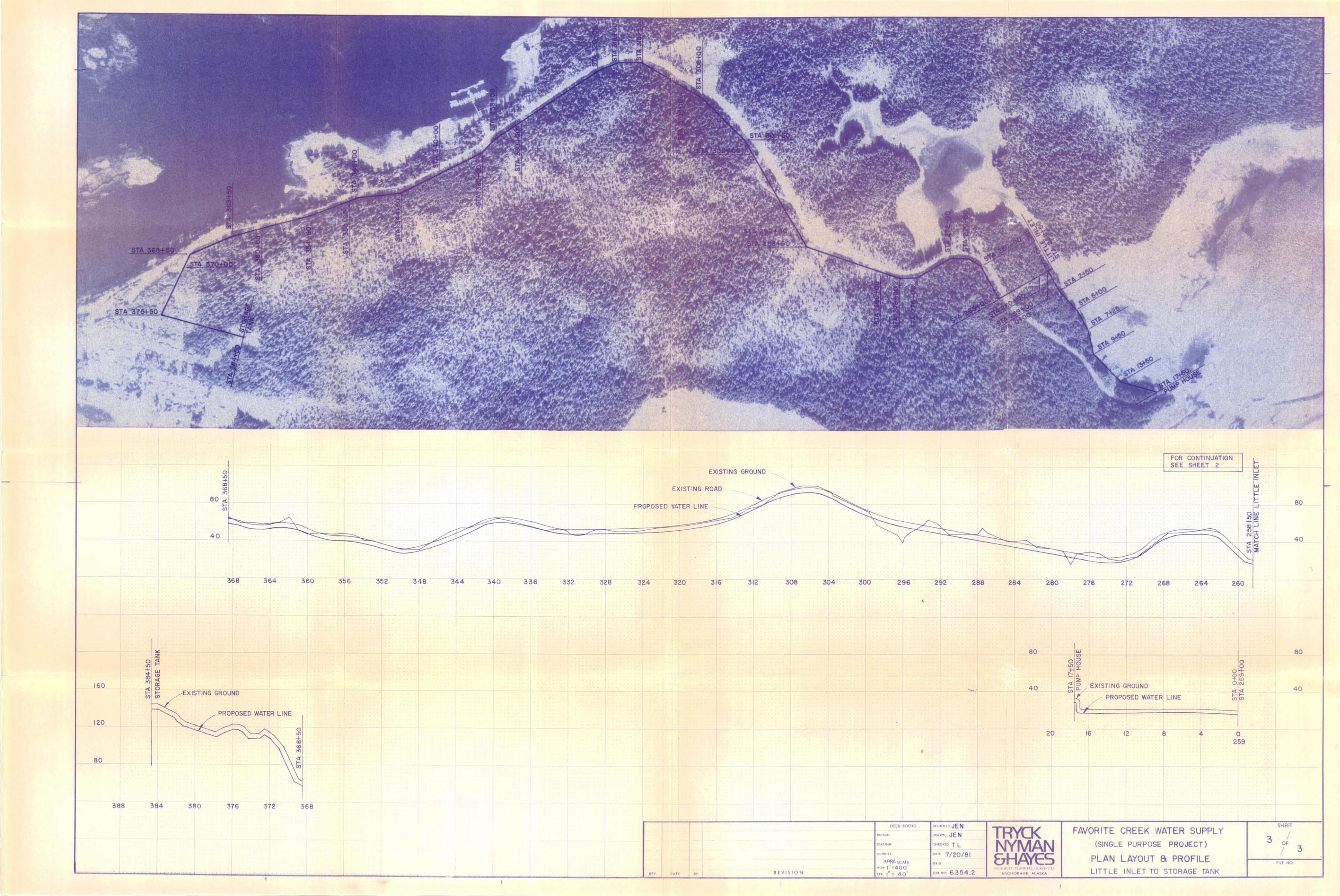
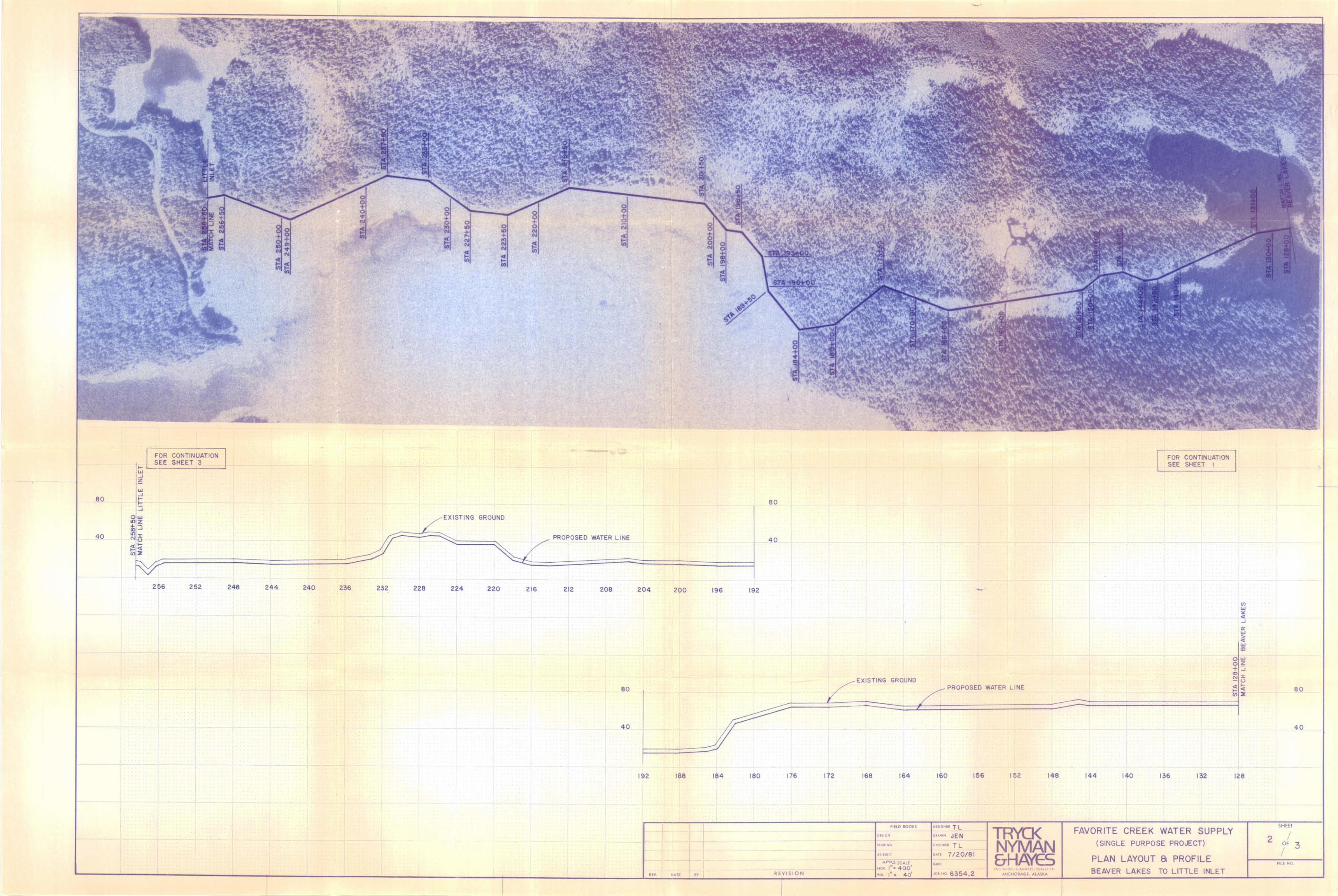
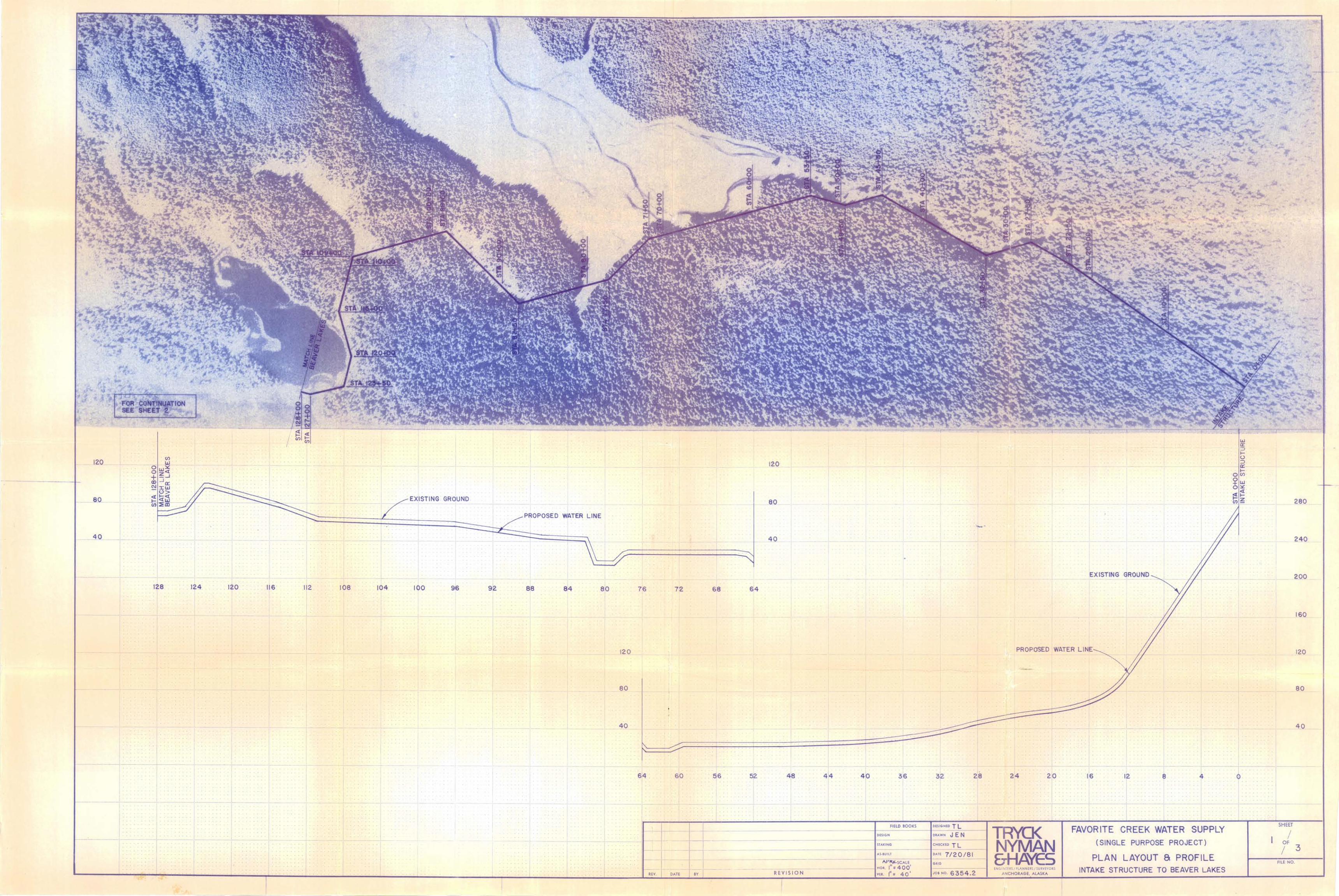
The route of the pipe will follow a line from the intake structure to the pro
posed site of the fish hatchery. From that point the route will cross between
Beaver Lakes, then to the shore of Ki11isnoo Harbor and along the shore to the fish
processing plant, see Figure 7. After crossing the Littl~ Bay Inlet at the fish
processing plant, a line will be placed along the road to Angoon where a connection
to the existing waterline could be made. Temporary use could be made Qf the exist
ing facilities such as the water treatment plant and water storage tank.
-35-
J INT AKE STRUCTURE:
------ --~ ---
-t- I
- .& L ~ V..4 7 / 0 ,.,..~ -
~
-- . lit -III!
- , --- -.:t. ~ .,
" ~ .. ~
---.-~
~ 0-.. 0 ...
~ " ... -" ~ illlllil-l-Hl£liltt~!-;ili ~' :-li -Ii iH' itH:l.4-~ ~ I
~ ~ -.. , -:-----
--=~ ~~'\\ ; .. .----" . ~~"'. ~
- \~~ , \
-,I,t..¥ /S.J.. ~1nF ~~~~tt====--=-\=~~~ ~U~~~~~~~~
~5;£C TION-.J i
r ~--~~~~----~~-------------r----------------~ __ ~~--------------~ ....... DU. ~4 SCALE /11
.. 1.0 I TR'YCK INT AK E eH", DATE 11· / ,~c NYMAN STRUCTURE ~~ NO. SHEET OF &HA'tES SCHEMATIC DESIGN
FIGURE 9
-36-
However, a new water storage tank of a capacity not less than 200,000 gallons
(300,000 gallons as a reserve for firefig~ti~g - 100,000 gallons reserve at the
intake structure) will have to be installed. Although water supplied from the
Favorite Bay Stream System is of excellent quality (particularly in comparison with
the existing source), general requirements dictate that filtration should probably
be provided eventually. Therefore, a treatment facility will ultimately have to be
installed.
The location of the new water treatment plant is proposed to be at the Small
Inlet (see Figure 7), the new water storage tank would be constructed at the site of
the existing one. Included as Appendix C are plan profiles of the above described
pipeline route.
E. EXCAVATION
The terrain along the future waterline alignment has been examined and some
technical evaluation of the excavation pattern has been accomplished. The main
purpose of this analysis was to evaluate the extent of rock excavation (blasting and
removal) compared to sail excavation for the waterline trench. It is anticipated
that ~ost of the material excavated will be used for backfill and for access road
construction. It is assumed in general that 25% of the excavation will be in solid
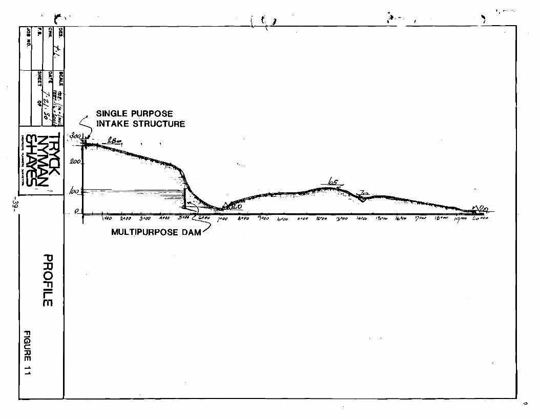
rock. However, in the vicinity of the intake structure, in part of the beach line
(from Sta. 240+00 to Sta. 255+00 = l500/ft.) and in the line along the road from
Small Inlet to Angoon, a ratio of 50% rock excavation is expected.
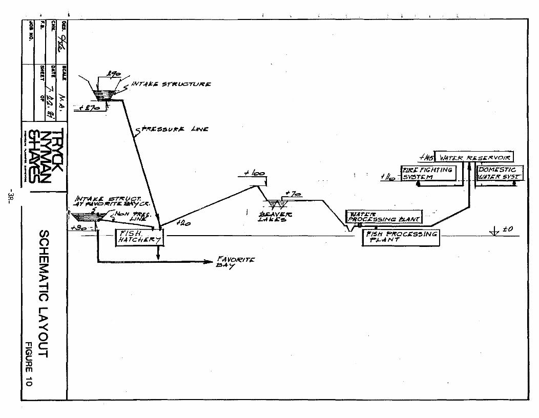
Some bedding material appears to be also available along the beach section of
the line approximately at Sta. 220+00, see Figures 10 and 11.
-37-
I W ::X> I
R II P
L
:'"
"
en o :::t: m ~ » ~ o r » -< o ."c
i5 -t c ::n m ..... o
i n 0 z 1= "
n5H 'f='!fOCI&S5/NG ____ ~.Jt"'--:l:_O_ PJ-.,fNT
• ~~~rr='~' _______________________________ L \~/ ____________________ "_·'-'
~ =" n 0 • !I' ~ 1= z p
...... -----4 I
W I-D I
.....
.....
'"U ]J o 11 -r m
SINGLE PURPOSE . <- INTAKE STRUCTURE
:4t'JOli_ . ,
£00
1(70 E-,=:--o-===_ .===-=====--====_~.,,=~===, --=--== ... _= ___ ==_=. ~
MULTIPURPOSE DAM
V r __ " • ,
F. CONSTRUCTION
Construction Procedures:
Construction procedures in general shall be governed by standard utility
construction Dractices. The construction activity schedule of this alternative
assumes that only a single purpose structure for the water supply for Angoon and the
fish orocessing plant will be built, and thus no provision is being made for other II
facilities (such as an access road, powerlin~, etc.).
The layout presented in Appendix C is based upon available information;
however, it should be understood that adjustments will have to be made resulting
from more detailed surveys.
Clearing and grubbing is anticipated to provide access and working space for
construction machinery, -including the excavated material berm and pipe storage. An
arbitrary 20' wide construction area has been chosen. The location of the waterline
has been chosen so that disturbance of the terrain can be minimized.
Excavation is expected to be partly in rock as described previously. Some
deviation during construction from the original layout might be utilized to minimize
rock excavation. Also an option to use insulation rather than depth of bury for
frost protection is available.
Pipe installation should utilize selected bedding material. Some bedding
material may have to be hauled from sources such the beach areas near Killisnoo
Harbor. Timber plank or synthetic fiber underlay reinforcement might be needed in
areas where deep peat subSoil is encountered (such as in the Beaver Lakes vicinity).
-40-
PiDe material is expected to be ductile iron with cement martar lining. An
alternate pipe material ~ould be high density polyethylene. This material is
lighter and would permit handling without the need for heavy construction
equipment. So~e difficulties in installation are anticipated due mainly to the
remoteness of the construction area. To mini~ize future maintenance, a quality in
stallation is required. A lower quality installation could considerably raise the
maintenance costs reflected in this study. The economic evaluation of this project
does not anticipate high maintenance costs and the quality of the installation could
affect the final feasibility of this alternative.
Nonclassified earth fill material shall be taken from the excavated ~ateri3l;
however, some basic selection will be required. Although no more than minimum com
paction by use of the construction machinery overruns will be needed, care shall be
taken to avoid future erosion by running water.
-41-
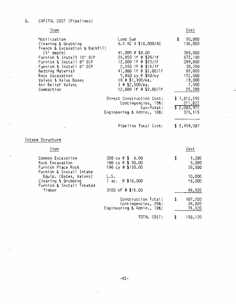
G. CAPITAL COST (Pipelines)
Item
'1obi 1 i zat ion Clearing & Grubbing
Lump Sum 8.5 AC X $16,000/AC
Trench & Excavation & Backfill (4 1 depth)
Furni sh & Insta 11 10" 01 P Furnish & Install 8" DIP Furnish & Install 6" DIP Bedding r~aterial Rock Excavation Valves & Valve Boxes Air Relief Valves Compaction
Intake Structure
Item
Common Excavation Rock Excavation Furnish Place Rock Furni sh & Install Intake
Equip. (Gates, Valves) Clearing & Grubbing Furnish & Install Treated
Timber
41,000 @ $9.00 25,850 If @ $26/1f 12,600 If @ $23/1f 2,550 If @ $15/1f
41,000 If @ $2.00/1f 2,450 cy @ $50/cy
18 @ $1, 100/ea. 3 @ $2,500/ea. 12,600 If @ $2.00/1f
Direct Construction Cost: Contingencies, 15%:
Suo -Total: Engineering & Ad'Tlin., 18%:
Pipeline Total CJst:
200 cy @ $ 6.00 100 cy @ $ 50.00 190 cy @ $150.00
L.S. 1 ac. @ $ 16, 000
3100 bf @ $15.00
Construction Total: Contingencies, 25%:
Engineering & Admin., 18%:
TOTAL COST:
-42-
Cost
$ 50,000 136,000
369,000 672,100 289,800 38,250 82,000
122,500 19,800 7,500
25,200
$ 1,81 2, 1 50 271,822
$ 2,083,972 375,115
$ 2,459,087
$
$
$
Cost
1,200 5,000
28,500
10,000 16,000
46,500
107,200 26,800 24,120
158, 120

Summaiy - Small Creek Alternative
Pipelines: Intake Structur~: Water Treatment Plant: Reservoir (300,000 gal.)
$2,459,087 158,120 150,000 225,000
$2,992,207
-43-
\
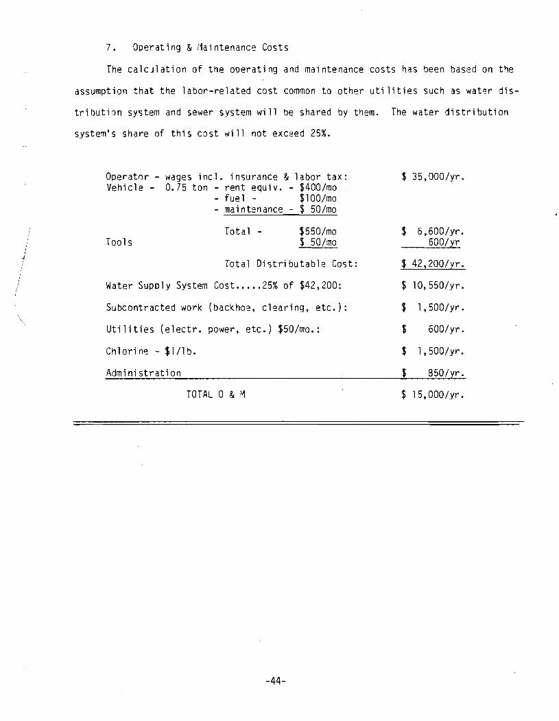
7. Operating & Maintenance Costs
The calculation of the operating and maintenance costs has been based on the
assumption that the labor-related cost common to other uti lities such as wat~r dis-
tributiQn system and sewer system will be shared by them. The water distribution
system's share of this cost will not exceed 25%.
Operator - wages incl. insurance & labor tax: Vehicle - 0.75 ton - rent equiv. - $400/mo
- fuel - $lOO/mo - maintenance - $ 50/mo
Total - $550/mo Tools $ 50/mo
Total Distributable Cost:
Water Supply System Cost ..... 25% of $42,200:
Subcontracted work (backhoe, clearing, etc.):
Utilities (electr. power, etc.) $50/mo.:
Chlorine - $l/lb.
Administration
TOTAL 0 & M
-44-
$ 35,000/yr.
$ 6,600/yr. 600/}.:r
$ 42,200/yr.
$ 10,550/yr.
$ 1 , 500/yr.
$ 600/yr.
$ 1,500/yr.
$ 850/tr .
$ l5,000/yr.
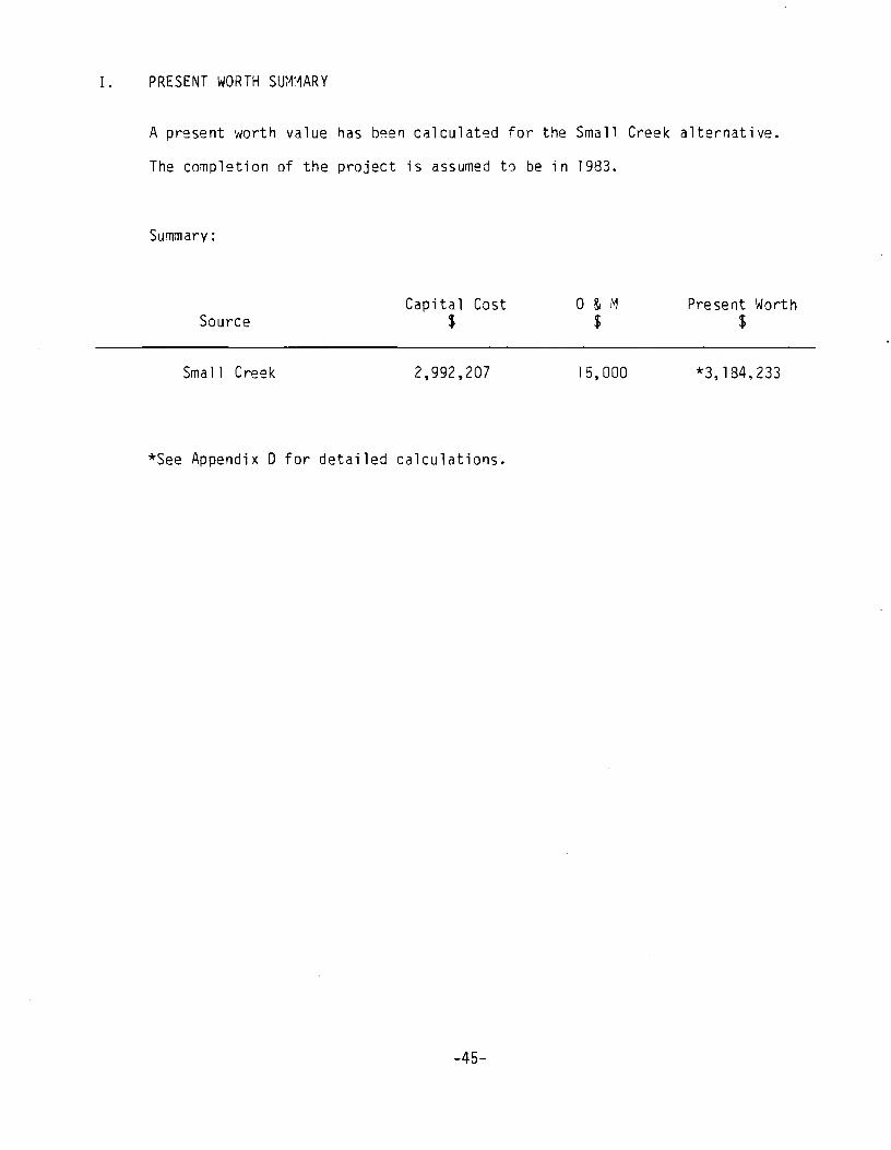
I. PRESENT WORTH SUMMARY
A pr~sent worth value has b~en calculat~d for the Small Creek alternative.
The completion of the project is assumed t~ be in 1983.
Summary:
Source
Sma 11 Creek
Capita 1 Cost $
2,992,207
*See Appendix 0 for detailed calculations.
-45-
o & ,"1 $
15,000
Present Worth $
*3,184,233
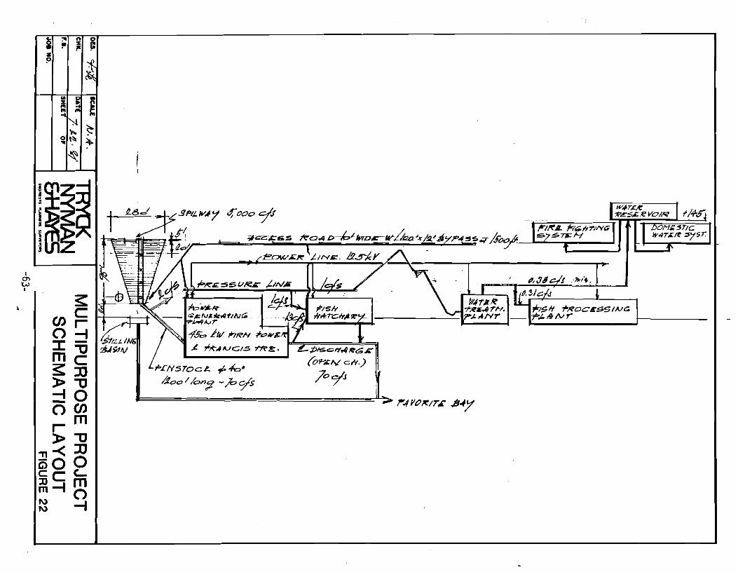
V. ~ULTI-PURPOSE PROJECT FAVORITE CREEK WATER & ENERGY SUPPLY SYSTEM
A. INTRODUCTION
This project was born in an effort to provide the people of Angoon. Alaska
with a stable source of water and electrical p~wer (in association with the
development of a salmon hatchery under the State of Alaska Private Non-Profit
Hatchery Program). Favorite Bay Stream was selected for investigation because local
knowledge indicated that there was substantially more flow in the stream than
suspected by others looking for potential hydropower sites. In the hydropower re-
connaissance of Thayer Creek accomplished by Harza Engineering Company in 1979. no
mention of Favorite Bay Stream was made beyond the indication that a map survey of
other streams in the area had been made. but none was found more attractive than
Thayer Creek.
-46-
.. DU.
CHI(.
F.e.
0101 NO.
SCALE )1, .. / NIL£
.j~. II 0'
TRYCK NYMAN &HA'tES
-47-
.. .. .,. • .CO
-J!
~~ .~.~
'oJ"
-~ 0 0
qtJ -g o. .. 0
• • 'Q
... tI 0
• 0 .;-~
MULTIPURPOSE PROJECT PLAN LAYOUT
I I
-+l \
FIGURE 13
0101 NO.
TRYCK NYMAN &HAYES
-48-
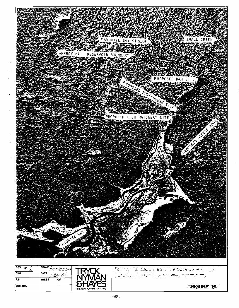
Preliminary investigation of the Favorite Bay Stream for use as. a potential
salmon hatchery site revealed that the stream also appeared to have significant
hydropower potential.
B. LOCATION AND LOCAL TOPOGRAPHY
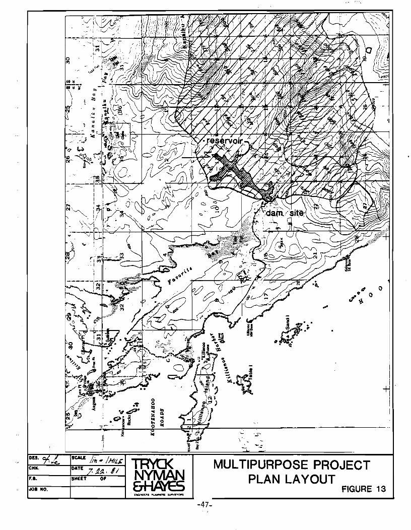
The project is located approximately 4.5 miles from the village of Angoon (see
Figures 13 and 14). The proposed dam site and reservoir are contained within Sect-
ions 10, 11, 14, 15 R51S, T67E, Copper River ~~eridian. Tf'Je geodetic coordinates of
the proposed dam site are 134°28 1 30"W, 57°27 I 06"N.
The terrain in the drainage basin is heavily forested and rises from sea level
at Favorite Bay to over 3000 1 MSL on the south side of the drainage basin. Total
drainage basin area is 20 square miles.
The proposed dam site is a narrow canyon through which Favorite Bay Stream
flows just before it meets salt water in Favorite Bay. The base of the stream at
the site is approximately 20 1 ~SL and the tops of the canyon walls are approxi~ately
-110 1 MSL. The distance between opposite sides of the canyon at 110 1 MSL is approxi-
mate 1 y 280 ft.
If the dam were constructed such that the water level in the reservoir was
115 1 MSL, the resulting reservoir would be as shown in Figure 13. The surface area
of the reservoir would be approximately 225 acres. If the average dept, in the re
servoir was 55 1, then the reservoir ~ould contain approximately 12,~75 acre-feet of
water. If the uppermost 20 1 were regulated for power generation, then approximately
4500 acre-ft. could be regulated .
.s- (' 1/(" ~ I,
-49-
The local geology in the region of the reservoir is oredominato.ly paleozoic
and mesozoic undifferentiated schist. Geologic mapping of the area indicates that
the bed of Favarite Bay Stream in the area 'Nhere it flows northeast-soutl1west is
along an inferred fault line. The dam site, however is north of the fault line.
The risk of seismic activity in this area, as in most places in coastal Alaska, is
significant and must be accounted for in design.
C. HYDROLOGY:
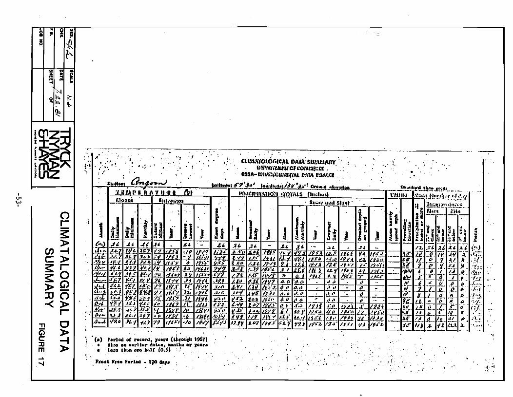
The general climate in the project area is maritime occasionally affected by
dry air from Canada. Tl1ese conditions produce a mild climate with a substantial
amount of precipitation. The quantity of precipitation in a specific location
varies considerably depending upon orographic effects. The maritime influence tends
to moderate temperatures. Summer highs are rarely above 70°F. and winter lows
rarely below 15°F. A Climatological Data Summary is included as Figure 17.
Temperature and precipitation data are summarized for Angoon based upon 26 years of
record.
Mean annual rainfall in Angoon is 37.9 inches, somewhat lower than average for
Southeast Alaska. The drainage basin, however, is at a much higher average
elevation (985') than Angoon and has a greater degree of exposure to the southeast.
Each of these factors will tend to increase annual precipitation and streamflow. A
climatic factor of the basin favorable to both hatchery and hydro development is the
relatively small change in mean monthly rainfall throughout the year.
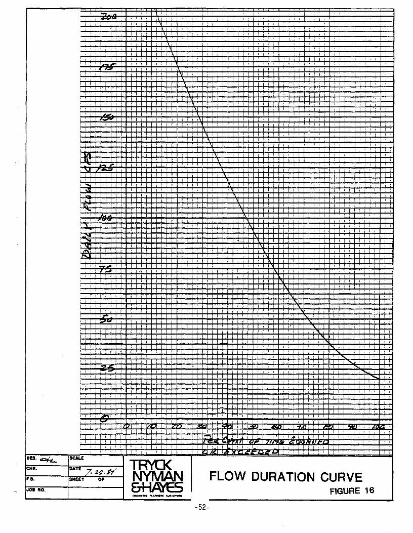
Favorite Bay Stream is ungauged; therefore, no accurate data on streamflow is
available. There is, however, considerable stream flow data available on streams in
-50-
L =" n 0 0 ~ :It != • !II z
~ ?
t>' IjO 0 • :It
= S ... ... ... -4
Or. ~ 'tic" 1-~
.£00
/90 1\ /80
70 \
160 t.~ \ /&>-
I
" 140
Ijo \ /1.0 \
I <.Tl --' I
en -< z --I J: m --I -(')
J:
#0 \ loa \
'\ 10
\ 80 r.....
~ 70
'" 1.60 ().5, ~
-:\*' 1\ ~~ 01
-< Po C ]J 10
J ~
0 I () i
G) ocr. Nov. hc. JAN.
"TI ]J
G) » c "'C JJ J: m ..... 01
~------ .-~- ~- .. _._- -- ------ -
------ ----~- --~ -_._.-
- .- ---- - - ~
cJ!.·~ 17 v \! I - - ._- ---- ~- -
~ .. / \ - ~- --_. - ~
/ 0_- _! \- - --~ --- ----_._--
/ / / , \
v :
~ II ------i
/ i I
.------ --
/ 1 I .- - - ~
._--
v-5 / 7- i
- I --- --- - ------
~ [7 , 1.
~
f-- 1--' ----- . - -------
-- - ----_ .. -
1-.3. ---- -- f--- - --- . ---- -
! f---t --- -~~-~-- 1---- 1------ -~--~ --"--_._--- --
I I i I I I
F- HA ~R. MA JCIN. JVL AtA 7 1:;. 5£ ~ OCT.
1. .1. i.e::>. I7tJ-P -.Fe::::> C;"..:;
L. .5: I· It' t!J~ - / S.1. c;;tr,:;
~. 7-,l.. /780 - ,t.8 c;.~$
t (,t-A'r~~,cN,L /' ~7 7;t;:~/t?P.J
10.//. 1780 ~ C~:;; .L. £.. /7.8/ - .3 (1/'"$
4.4. /74/ -/.11 ~.--~ 6. 8. PJt!J/ - 6.7 t:;P'':;
..., 'AI ..--! , ! \I I
'" I , ,
, 1 ,\I
1 \ 1 1\
! I ~-,. I ! I I I
,- ' , I ,
\l , , \
, , , , I 1 ... ,
r.."., , I
I I I , , ,
1 I
, till
l\~ !
,... .... ,.. ,'\,j " M.iii
,;'" ..: .... '" 11>: '
I ~ , , ........ , IVI- I
I " i I I I I
,~
.~ ....
,I"
10.1 ... ! , -1 , ,I
I I , !
i 1 ,
1.flO· ,
1"2..11: , 1 I : ;-
I . !
1 , 1 , ! 1 1 I I lA"\ • ! , I ! -I . i i 1 I
LI 1/::;11 '7 ")I
, , , I 1 1
I I
DU. c:::H.... CHIC.
F.B. SHUT 0'
.108 NO.
t
1
1
,
"
~
, 1 , 1
I , I
I i i , I I
I I I , I
I I I , , ,
, , I I ,
I I
1 I
\1 , \ I
1'\ \
I :\ , !
1\
I I
11 1\
I 1\
,\
\
I I
1
I I
I , 1 I
!'
I 1
, ... rll I 1 I 1 i
I I
, , I
t ,
! 1
, 1 I
1 ! 1
I I
I i
, I
I ,
I I,
.. "
, I
, 1,\
"
I , 1 I 1
, , : , I I
I 1
I I
I I
Ii· I i If'
, ,
I , ,
t , , 1
I i
, , , , I
I , ! ,
1
I I , 1 1
t , 1 i
I , , i
! 1 1 ,
, 1 ! 1
, , 1
I
1 1 1 , , , ! I ,
I !
! I ! ' , , I I
! f , I 1
1 I I , I , ,
1 ,
iii I
1 1 , , ., f 1
i '
I , , 1 1 , 1
I I
I I I 1"-1 ! I
I 1
I ,
1 I
1 I
, !
, I
1 I
I ...... , I
, i ....... ! '" I I
1 I t l I •
! I i
, :
, !
, I , ,
, 4';11'1, I ! , I
! I , I I
L'T IIW .~ U;UIlfM I '
FLOW DURATION CURVE FIGURE 16
-52-
!
I
, 1
1 ,
. ,
I <..T1 W ,
~ =" n g
!II z J: • ~ z 1Z ~
l' CIt g • z ~ S III III III ...
o~ ~ ... ~ \-~
o r--~ »
(/)--1 C» ~r ~O »~ lJO -<»
'TI G) c: :::tJ m
r C » --I »
, ,
, "" ; , '
,.r1od 01 r.cord. ~1I.r. hllrolida 1961) Aho Dn lIal'UII .. dn ...... IOOnUI" Dr )'o"r" Looo ,,'!:I,n ono tlAlt (0.5) ,,', : ' ,
'1'0" , ...... dod - 110 •• ,. . ",
I
--
. ','
I,
"
," ..... to ,. " ,
:.: . '
'. ,', . "
'f' .j .," I
· the same region, i.e. less than 25 miles away and in similar terrain. This data has
been utilized to produce a stream flow per square mile of drainage basin figure re
presentative of the region. Since basin average elevation is known to have
measurable effect on precipitation, a correction of .003 CFS/square mile per foot of
basin elevation was incl~ded. The mean annual runoff derived from the analysis of
gauged basins was 6.02 CFS/square mile. ~hen corrected f~r basin elevation, this
figure was reduced to 5.45 CFS/square mile.
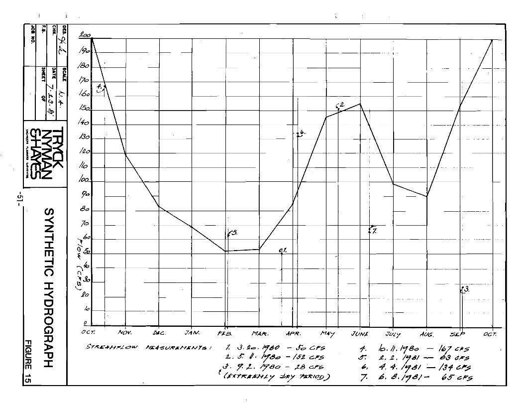
A synthetic hydrograph for Favorite Bay Stream was developed by distributing·
average annual streamflow over the year. This was done based upon gauged data from
Hasselborg Creek, located approximately 16 miles north of the project area, for
which there is 16 years of excellent quality streamflow data. The results of the
distribution are presented in Figure 15. As indicated in Figure 15, low flows occur
in late winter and average approximately 52 CFS. This is followed by an increase in
flow from melt water in May and June which, in turn, is followed by a drop to ap
proximately 90 CFS in August. Stream flow rises to a peak of about 200 CFS in
October.
This synthetic data has been supported by stream flow measurement made by
Tryck, Nyman & Hayes. Results of these measurements are presented in the table
below.
-54-
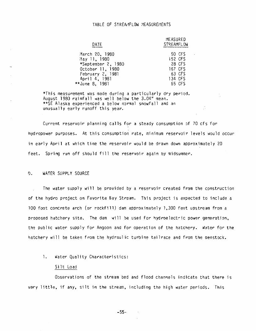
TABLE OF STREA~FLOW MEASUREMENTS
DATE
March 20, 1980 ~1 a y 1 1, 1 980 *September 2, 1980 October 11,1980 February 2, 1981 April 4, 1981
**June 8, 1981
MEASURED STREAMFLOW
50 CFS 152 CFS
28 CFS 167 CFS
63 CFS 134 CFS
55 CFS
*This measurement was made during a particularly dry period. August 1980 rai nfall was well below the 3.04" mean. **SE Alaska experienced a below nQrmal snowfall and a~ unusually early runoff this year.
Current reservoir planning calls for a steady consumption Qf 70 cfs for
hydropower purposes. At this consumption rate, minimum reservoir levels would occur
in early April at which time the reservoir would be drawn down approximately 20
feet. Spring run off should fill the reservoir again by midsummer.
D. WATER SUPPLY SOURCE
The water supply will be provided by a reservoir created from the cpnstruction
of the hydro project on Favorite Bay Stream. This project is expected to include a
100 foot concrete arch (or rockfill) dam approximately 1,300 feet upstream from a
proposed hatchery site. The dam will be used for ~ydroelect~ic power generatiQn,
the public water supply for Angoon and for operation of the hatchery. Water for the
hatchery will be taken from the hydraulic turbine tailrace and from the penstQck.
1. Water Quality Characteristics:
Si It Load
Observations of the stream bed and flood channels indicate that there is
very little, if any, silt in the stream, including the high water periods. This
-55-
conclusion se~ms reasonable since there is no glacial activity in the drainage basin
or in the surrounding sediment trap. Any silt that may be carried in the stream
flow will fallout in the reservoir and silt is not expected to cause a problem.
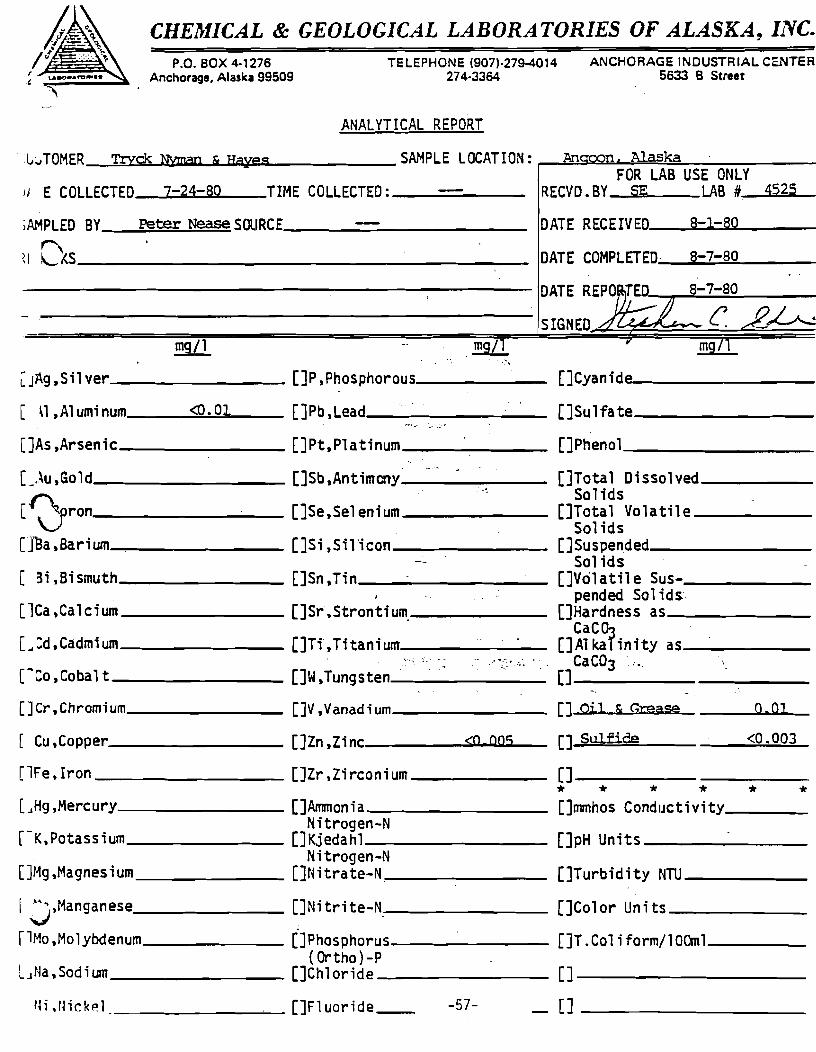
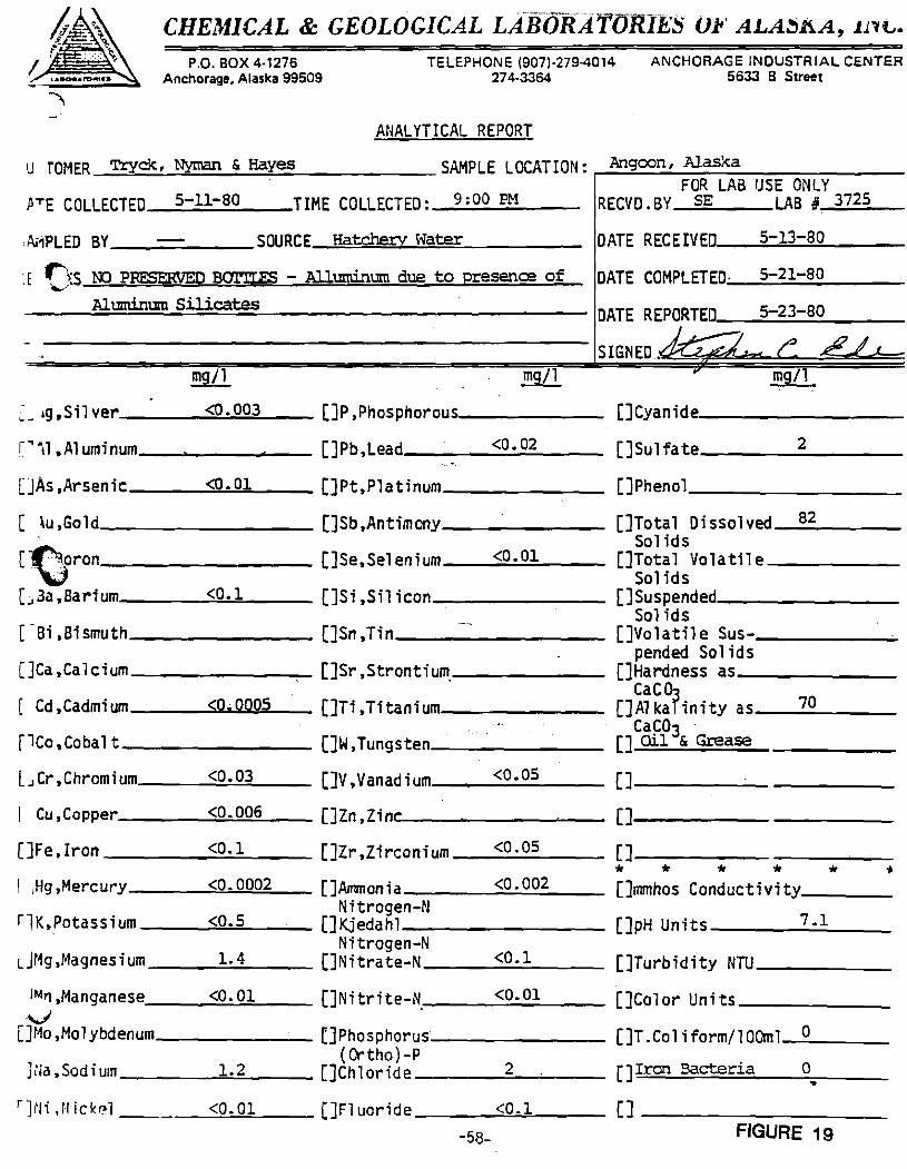
A water quality analysis has been included as Figures 18 and 19. It indicates
that there are no significant quantities of any detrimental materials in the water.
The samples for the analysis were taken at the site of the proposed hatchery in May
1980 and July 1980.
2. Temperature Regime (including the daily temperature range and the
seasonal highs and lows):
Stream temperatures range from wintertime lows of 32°F. to summer highs of
53°F. during July. USGS water quality records from streams in the Angoon area indi
cate that temperatures may go as high as 70°F., although this has not been observed
in Favorite Bay Stream. The reservoir will have a substantial effect on water
'1 temperature. The summer reservoir temperatures are expected to range from J_~oF. 'at !
the bottom to over 75°F. at the surface. The warm surface laye~ in this case ~ill
be quite thin. Winter temperatures will range from freezing at the surface to 39°F.
at the bottom. It is anticipated that the intake structure will be constructed such
that water can be selected from different lake levels in order to maximize the tem-
perature of the influent when desirable (for hatchery use).
4. PRELII"1INARY DA\~SITE DESIGN CONCEPTS
Preliminary work on the dam site indicates that the dam structure may be a
concrete thin arch if the foundation rock is competent or a rockfill dam with an
-56-
CHEJtlICAL & GEOLOGICAL LABORATORIES OF ALASKA, IJ.VC.
P.O. BOX 4·1276 Anchorage, Alaska 99509
TELEPHONE (907)-2794014 ANCHORAGE INDUSTRIAL CENTER 274-3364 5633 B Street
ANALYTICAL REPORT
'l.,." TOMER Tryck Njanan & Hayes SAI"IPLE LOCATION: Alaska FOR LAB USE ONLY
liE COLLECTED 7-24-80 TIME COLLECTED: __ ~ __ _ RECVD. BY SE LAB #,_4=5=25",---
iAMPLED BY Peter Nease SOURCE, ________________ _ DATE RECEIVED'_--lo81....-.,;1-;.iII,8.l;C.0 __ _
~I ~S _______________________________________ _ DATE COMPLETED, 8-7-80
8-7-80
SIGNED
. .!!!SL..L L JAg ,Sil ver ___________ []P ,PhosphorolJs, ________ []Cyanidl:Me _________ _
[ n ,Aluminum <0.01 []Pb,Lead ________ []Sulfate ________ _
[]As ,Arsenic []Pt,Platinum _______ []Phenol ________ _
[_,~u,Gold---______ []Sb,Antimcny_' _"'_' _' ____ []Total Dissolved _____ _ .r'\. ...... So 1 ids
['. '\!.pron []Se,Selenium _______ []Total Volatile ____ _ V Solids
UBa ,Barium []Si ,Sil'icon []Suspended ______ _ Sol ids
[ 3i ,Bismuth []Sn ,Tin []Volatil e Sus-______ _ , pended Sol ids'
[lCa ,Calcium []Sr,Strontium. []Hardness as ___________ _ CaCa,
[ ... :d,Cadmium []Ti,Titanium []Al kaT'inity as _____ _
[-:0 ,Cabal t _________ · []W,Tungsten,_' _'''_' _"'_"_' ____ ,.i-_/_;.'._~ _. [] CaCa3 C'"
- .
[]Cr,Chromium, ________ []V,Vanadium, __________ _ [] Oil & (',x:ease Q.Ol
[ Cu, Copper____________ [] Zn , Z i nc. _____ .-.;:w<Q"-W,OQI.&.S"--_ [] Sulfide <0.003
[lFe.lron []Zr,Zirconium ______ [] _______________ _
* * * * * * L,JHg,Mercury ______________ []Armnonia ________ []mmhos CondlJctivity ___ _ Nitrogen-N
r-K,Potassium []Kjedahl ________ []pH Units _____________ _ Nitrogen-N
[Jr~g,Magnesium _______ []Nitrate-N _______ []Turbidity NTU _____ _
I J,r~anganese []Nitrite-N .. __________ []Color Units ______ _
rlHo ,Molybdenum []Phosphorus []T .Col i form/10Oml ______ _ (Ortho) -P L JNa, Sad i um ___________ []Chl oride _________ [] _________________ _
rH.rl;ck~l _~ _____ ---'-_ []Fluoride_ -57- [J __________ _
CHEMICAL & GEOLOGICAL LAiiljRATlJRIES Or' ALA~AA, Jll~.
P.O, BOX 4·1276 Anchorage, Alaska 99509
TELEPHONE (907)·279-4014 274·3364
ANALYTICAL REPORT
ANCHORAGE INDUSTRIAL CENTER 5633 B Street
u raMER Tryck, Nyman & Hayes SAMPLE LOCATION: Angoon, Alaska ~~--~------------------FOR LAB USE ONLY
PTE COLLECTED 5-11-80 TIME COLLECTED: 9: 00 PM RECVD • BY SE LAB /J 3725
,Ai1PLED BY ______ SOURCE Hatchery Water DATE RECEIVED, _____ 5;....,-=13;..,.-....:;.8,;;.,° __ _
'. E US NO PRESERVED BQM1FS - Alluminum due to presence of
Aluminum Silicates
DATE COMPLETED· 5-21-80
5-23-80
SIGNED .
.!!!lli mg/l
C _19 .Sil ver ___ ~<O:::.:·:..;:0;.:;03=__ __ []P , Ph os ph orous,_______ []Cyanide---------
C' i 1 • A1 urni num < []Pb, Lead ____ <,;...O .,;...0.....;.2___ []Su 1 fa te ______ 2 ___ _
[jAs,Arsenic <0.01 []Pt,Platinum _______ []Pheno1 ___________ _
[ ~u.Go1d (]Sb,Antirnony _______ []Tota1 Dissolved __ 82 ___ _ Sol ids
[-~.,.:(oron []Se,Se1enium __ ~<0~ • ...;:::01=-__ []Tota1 Volatile _______ _ ... "., Sol ids
C,·3a,Barium <0.1 []Si ,Sil icon []Suspended ________ _ Solids
[-6i .Bismuth ________ []Sn,Tin []Vo1ati1e Sus-______ ~
[]Ca,Calcium ___________ []Sr,Strontium. _____ _
[ Cd,Cadmium ___ ....;<>:III:O..a.;;O-..:lOgO~5 ___ []Ti ,Titanium ______ _
rlCo,Coba1 t []W,Tungsten ______ _
l.J Cr, Chromi um, ____ <....;,::0:.,:..,.=.:03=---__ []V, Vanad i um, ___ <_0._0_5 __ _
I Cu,Copper ____ <~0.:..;.0=O:.:.6 __ []Zn,Zin,~c __________ _
[]Fe. Iron _____ <...;.:0...;;.,.1=--__ []Zr ,Zi rconi urn __ <_0_. 0_5 __ _
pended Solids []Hardness as ______ _
CaC03 []A1 kaT inity as __ 7;...0 ___ _
CaC03 . [] Oil & Grease
[]---------[]I------------------_
[]----------* * * * * I ,Hg,Mercury ___ --'<=0..:...0=O:,::O=.2 __ []Ammonia ___ --.......;<~0.;..:0..:..02::-__ []mmhos Conductivity ___ _
Nitrogen-N rlK.Potassiurn __ ~<~O:..:..;.5~ ____ []Kjedahl ____________ []pH Units 7.1
Nitrogen-N LJr1g,r4agnesium __ --.;1;;.., • ....;.4 ___ []Nitrate-N ____ <O_o_l ____ []Turbidity NTU _______ _
IM'1.r~anganese, _____ <.;.::.O~.O~l=__ ___ []Nitrite-N ___ <....:.O;;,.;; • ....;.O;;;;.l ___ []Color Units ______ _ V [Jr~o,Molybdenum rJPhosphorus []T.Co1 iform/100m1_0 ______ _
(Ortho) -p ] tJa • Sod i um ~ ____ -==l:.:.;o 2=--___ []Ch 1 or; d e ____ --=2:.-~__ []Iron Bacteria ° ..
__ <..:.:0:.:.. • .:.:01=--__ [JFluor;de ____ <~O!...:..o!=.l ___ [] __________ _
-58- FIGURE 19
i~pervious membrane; the structure in either case would have a crest width of ap-
proximately 280 feet and a height of approximately 100 feet. The proposed dam site
is shown on Figure 14.
A walkaround survey of the dam site revealed that the bedrock is predominantly
schist and appears to be quite shallow. Extensive geotechnical evaluation of the
site would be required before a decision on the applicability of a particular type
of structure can be made.
F. RESERVOIR REGULATION
Ii I
If the final reservoir configuration is similar to that depicted in Figure 13,
the regulated storage will be approximat6f~ 75 days during minimum flow periods. \',,---
Although no definite decisions regarding reservoir regulation can be ~ade until the
reservoir area is mapped at large scale, this initial work indicates that the reser-
voir can provide 70 cfs for po~er, hatchery, and water supply use, year round in a
norma 1 water year. A flow of thi s quant i ty wi 11 produce 4,~0-500 KW of fi rm power.
Substantial additional work 'Nill be necessary to confirm these preliminary
estimates. It is expected that the hatchery water will come from the turbine
tailrace but the approximately 2 CFS water supply will have to come from upstream of
the turbine in order to have sufficient pressure so that transmission to Angoon can
be accomplished without additional pumping.
-59-
G. PENSTOCK AND POWERHOUSE
It is expected that the powerhouse will be constructed either at the hatchery
site (or at the base of the dam alternatively). If constructed at the hatchery
site, a BOO' 40" penstock would be required (if constructed at the dam site,
penstock requirements would be reduced substantially, but a 1200' hatchery
influent/water supply line of approximately 20" diameter will still be required).
It is anticipated that the power generation equipment would be Francis typ~
reaction turbines driving synchronus AC machines. Two units, each rated at
400-500 KW would orovide the necessary capacity and reliability.
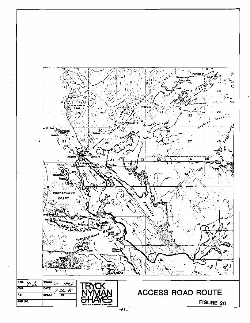
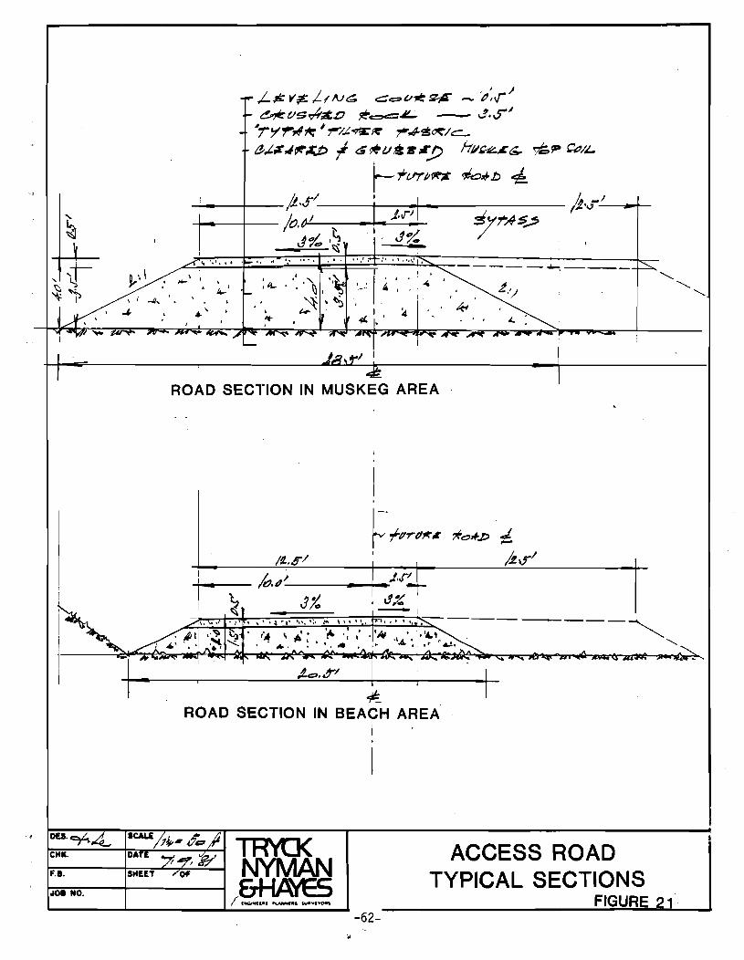
H. ACCESS ROAD AND TRANSMISSION LINE
An access road from Angoon will be required to facilitate construction and op
eration of the facilities and provide a route for the power transmission line and
the waterline. A suggested route is shown on Figure 20. The terrain along the pro
posed route includes sections of highly organic, high moisture content muskeg soils
interspersed with shallow bedrock. A typical section suggested for the roadway in
muskeg areas is shown in Figure 21. In areas where Shallow bedrock is encountered,
six inches of crushed aggregate base will be sufficient to provide a driving
surface. The total length of new roadway needed to access the hatchery site will be
approximately 4.4 miles. The power transmission line will follow the road right of
way and, depending upon the powerhouse site, will be approximately 4-1/2 miles long.
-60-
DU.
CHI(,
F.B,
0101 NO.
i-'
I I !
'\', , , .
"
SCALl /;i') - /I1IL£ DATE . ~!2., ~. SHEET OF
TR'ft]( NYMAN &HAYES
-61-
23 , , , \0', C~·' j
----- ~v , 'Go ,/
" ..
ACCESS ROAD ROUTE FIGURE 20
~L;'l...:.':':':'" '..:..:' '~'~""";-';;".' "fi.-'"";'",,,' .~. ~'=' '=t=" .:::' .~I' .;.,.;.' '..;.,.;' •• .:...j. ••• .:.;::' ""-:;:::-_ - - __ ....., __ _
~~ I : .No- \ I \
• 10-' \ j -J/, '. \
eH.. OAT!
F.e. SHEET
0108 NO.
ROAD SECTION IN MUSKEG AREA
..... 1 ___ - /tfJ.tJ' ____ -+--J,,j1
I ~ J% -,\. ~.,. .: • ~' • : .. ,- '0' •• ~, :.-- \" I , --~
~ ROAD SECTION IN BEACH AREA
I
-62-
ACCESS ROAD TYPICAL SECTIONS
FIGURE
'-..
I . 0'1
W I
~
(J)~ 0--1 :::r:m"'O ~~ »"'0 :::!O O(J) rm »"'0
'T1 -< ::c Ci) 0 0 c: C c... ]J --I m m 0 ~ --I
4"ooo~
~;,Css ~CM t::rk.tIvFDtr-W-/;t2a~K/fJ.'.B ,/",,4ss.;;r /5~ ___ "'----:l~ __ ""'"
It:>*'*-~ __ G;tl\J~'k.,RtJAJu._
~A.J'" -{50:::> 111/ nRH :!'e:>IV&
.L -I~,4IUCI.s "f1'f'g.
PfNSToc/:. .p~ .. /.100 Ilon:;z - /00
t>JSC;;~~ 1tr6 .. (op,c!Y cfi.)
70 cyJ
I. CAPITAL COSTS
Capital costs for this project were developed based upon an estimate of costs
for the major elements of the project. Reservoir clearing costs were felt to be
negligible since a contract for sale of timber could more than compensate for its
removal.
-64-
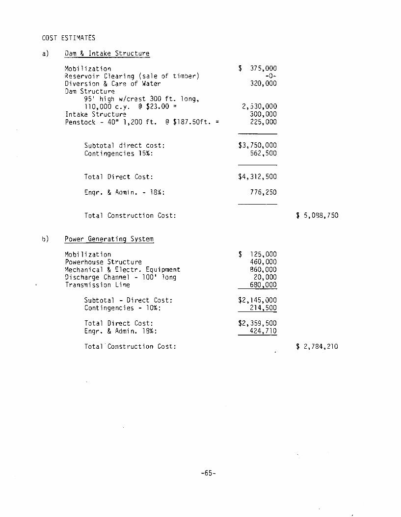
COST ESTIMATES
a) Dam & Intake Structure
Mobilization Reservoir Clearing (sale of timber) Diversion & Care of Water Dam Structur~
95 1 high w/crest 300 ft. long, 110,000 c.y. @ $23.00 =
Intake Structure Penstock - 40" 1,200 ft. @ $187.50ft. =
Subtotal direct cost: Contingencies 15%:
Total Direct Cost:
Engr. & Admin. - 18%:
Total Construction Cost:
b) Power Generating System
Mobil i z at ion Powerhouse Structure Mechanical & Electr. Equipment Discharge Channel - 100 1 long Transmission Line
Subtotal ~ Direct Cost: Contingencies - 10%:
Total Direct Cost: Engr. & Admin. 18%:
Total Construction Cost:
-65-
$ 375,000 -0-
320,000
2,530,000 300,000 225,000
$3,750,000 562,500
$4,312,500
776,250
$ 125,000 460,000 860,000 20,000
680,000
$2,145,000 214,500
$2,359,500 424,710
$ 5,088,750
$ 2,784,210
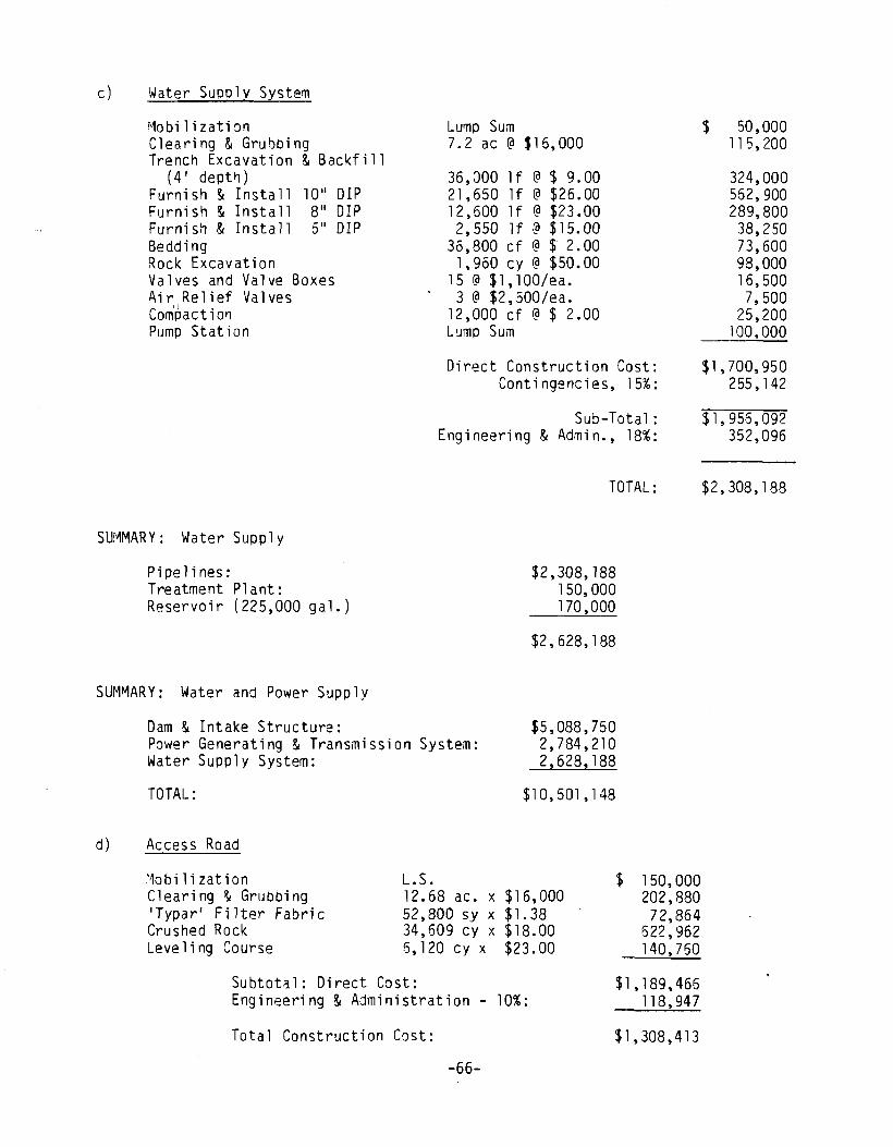
c) Water SUDP 1 y System
~10 b i 1 i z at i ~ n Clearing & Grubbing Trench Excavation & Backfill
(4' deptl1) Furnish & Install Furnish & Install Furnish & Install Bedding Rock Excavation
10" DIP 8" DIP 5" DIP
Valves and Valve Boxes Air Relief Valves
'I Compaction Pump Station
SUMMARY: Water Supply
Pipelines: Treatment P1 ant: Reservoir (225,000 gal.)
SUM~ARY: Water and Power Supply
Dam & Intake Structure:
Lump Sum 7.2 ac @ $16,000
36,000 1f @ $ 9.00 21,650 1f @ $26.00 12,600 1f @ $23.00 2,550 1f @ $15.00
36,800 cf @ S 2.00 1,960 cy @ $50.00
15 @ $1,100/ea. 3 @ $2,500/ea.
12,000 cf @ $ 2.00 L!Jmp Sum
Direct Construction Cost: Contingencies, 15%:
Sub-Total: Engineering & Admin., 18%:
TOTAL:
$2,308,188 150,000 170,000
$2,628,188
Power Generating & Transmission System: $5,088,750 2,784,210 2,628,188 Water Supply System:
TOTAL:
d) Access Road
11obi1ization Clearing & Grubbing 'Typar' Fi lter Fabri c Crushed Rock Leve 1 i ng Course
$1 0, 501 , 1 48
L.S. 12.68 ac. x $16,000 52,800 sy x $1.38 34,609 cy x $18.00 6,120 cy x $23.00
Subtotal: Direct Cast: Engineering & Administration - 10%:
Total Construction Cost:
-66-
$ 150,000 202,880 72,864
622,962 140,750
$1,189,466 118,947
$1,308,413
$ 50,000 115,200
324,000 552,900 289,800 38,250 73,600 98,000 16,500 7,500
25,200 100,000
$1,700,950 255,142
$1,956,092 352,096
$2,308,188
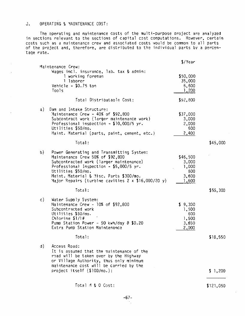
J. OPERATING ~ MAINTENANCE COST:
The operating and maintenance costs of the multi-purpose oroject are analyzed in sections relevant to the sections of caoital cost computations. However, certain costs such as a maintenance crew and associated costs would be common to all parts of the project and, therefore, are distribut~d to the individual parts by a percentage rate.
Maintenance Crew: l,.Jages inc 1. insurance, 1 abo tax & admi n:
1 working foreman 1 1 aborer
Vehicle - $0.75 to~ Tools
Total DistributaDl:! Cost:
a) Dam and Intake Structure: ~aintenance Crew - 40% of $92,800 Subcontract work (larger maintenance work) Professional inspection - $10,000/5 yr. Utilities $50/mo. r1aint. Material (parts, paint, cement, etc.j
Total:
b) Power Generating and Transmitting System: Maintenance Crew 50% of $92,800 Subcontracted work (larger maintenance) Professional Inspection - $5,000/5 yr. Utilities $50/mo. Maint. Material & Misc. Parts $300/mo. Major Repairs (turbine cavities 2 x $16,000/20 y)
Total:
c) Water Supply System: Maintenance Crew - 10% of $92,800 Subcontracted work Utilities $50/mo. Chlorine $1/1# Pump Station Power - 50 kwh/day @ $0.20 Extra Pump Station Maintenance
Tota 1 :
d) Access Road: It is assumed that the maintenance of the road will be taken over by the Highway or Village Authority, thus only minimum maintenance cost will be carried by the project itself ($lOO/mo.):
Total M & 0 Cast:
-67-
$/Year
$50,000 35,000 6,600 1,200
$92,800
$37,000 3,000 2,000
600 2,400
$45,000
$46,500 3,000 1,000
600 3,600 1,600
$55,300
$ 9,300 1,500
600 1,500 3,650 2,000
$18,550
$ 1,200
$121,050
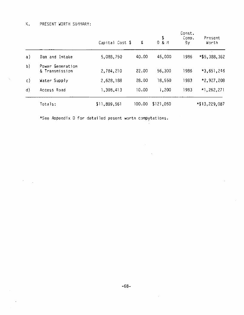
K. PRESENT WORTH SU~MARY:
Canst. $ Camp. Present
Cap ita 1 Cost $ ° & ;'" gy Worth
a) Dam and Intake 5,088,750 40.00 45,000 1986 *$5,388,362
b) Power Generat ion & Transmission 2,784,210 22.00 56,300 1986 *3,651,246
c) Water Supply 2,628,188 28.00 18,550 1983 *2,927,208
d) Access Road 1,308,413 10.00 1,200 1983 *1,262,271
Totals: $11,809,561 100.00 $121,050 *$13,229,087
*See Appendix D for detailed pesent worth comp~tations.
-68-
l. LAND AND LAND USE
The land in the reservoir area is (at the writing of this report) classified
as LUD I and recommended for inclusion into the National Wilderness Preservation
System. However, the 0-2 lands bill recently passed by Congress contains a refer-
ence to hydropower in Sec. 506.a(1)3 as follows:
"Subj~ct to valid existing rights, there is hereby granted Kootznoowoo, Inc .......... .
(8) The right to develop hydroelectric resources on Admiralty Island within Township 49 South, Range 67 East and Township 80 South, Range 57 East, Copper River Base and Meridian, subject to such conditions as the Secretary of Agriculture shall prescribe for the protection of water, fishery, wildlife, recreational and scenic values of Admiralty Island".
The bill further states that the cited legal descriptions can be changed with
the mutual approval of Kootznoowoo, Inc. and the Secretary of Agriculture.
Although the land upon which the proposed reservoir is located is selectable by
Kootznoowoo, it appears likely that the land will be included in a land trade for
land elsewhere, thereby returning it to its status of wilderness. However, according
to (B) above, the designation does not preclude the development of hydropower. The
possibility also exists that Kootznoowoo could continu~ their current selection and
thus the lands could be utilized for hydro development subject to concurrance of
Kootznoowoo and the Secretary of Agriculture.
-69-
VI. CONCLUSIONS AND RECOMMENDATIONS
A. INTRODUCTION
The following is an evaluation and comparison of alternatives discussed in
this study. Several criteria such as economy, technical suitability, serviceability
and social impact are considered in the evaluation.
The accuracy of the information used in this study is related to the early
stage of the project and to the accessability of information sources, thus the acclJ
racy is consistent with what should be expected from a reconnaissance level study.
The economic evaluations made in this study are based upon the estimates of
quantities and costs available to the authors during the preparation of this study.
It should be emohasized that the impact of the rapidly changing economic environment
can hardly be predicted exactly. The accuracy of the technical data used as a basis
for the quantities used in the estimates was affected by the non-availability of
-70-
ground surveys and geological data. A "Present Worth" was calculated for each al
ternative with 3% discount rate. The effects of inflation have not been considered
because inflation is expected to affect all the alternatives equally. Construction
time has been taken into account.
The proposed design of the alternatives evaluated reflects the Consu1tant ' s
(TNH) belief that a reliable water supply system with a high quality water source is
of highest importance not only to the future development of the community, but to
its very survival. A substandard water supply system with complicated, expensive
maintenance requirements has a poor chance of functioning in a developing Native
community such as Angoon, where financial resources are limited. The same reasoning
is applicable to the energy supply system.
The social impact of the various alternatives appears to be extremely
important. Angoon has the highest rate of unemployment in Alaska in spite of the
natural resources surrounding the community. At least a part of the reason for this
situation is inadequate development of resources coupled with a lack of
infrastructure.
B. ALTERNATIVES
1. Single Purpose Projects
Two alternatives for providing water only were studied:
o Upgrading of the existing system
o Creation of a new system.
-71-
The a lternat i ves were made cornparab I e wit hone anot her 'Jy des i gni ng t he'n so
that adequate standards for reliable water quality with a minimum requirement f0r
como1icated and costly maintenance would be provided.
a. Upgrading the Existing Water Supply System
The existing water source (Stromgren Creek) does not apoear to be suf-
ficient to provide an adequate water supply, so development of an additional water
source (McCarroll Creek) has been proposed. Ii
I
The piping system is oroposed to ')e
upgraded to an 8" ductile iron pipe that will create a permanent system providing
sufficient flow with minimum maintenance. The following costs were produced:
Construction Cost: $2,456,483
Oper. & Maint. Cost: $29,000/Year
Present Worth Value: $3,018,801
The existing system, if developed as proposed, would supply Angoon and th2
fish processing plant with an adequate water supply including a reserve for future
population growth. It could not provide a water supply for any other future indus-
trial development (such as a fish hatchery or for a higher water consumptive
industry such as shrimp, bottom fish and other diversified processing).
The construction of the water pipeline under this alternative would require
construction of a construction road along parts of the new waterline on the north
side of Kootznahoo Inlet. The future use of such a road would be limited.
The system involves a submarine crossing of Kootznahoo Inlet approxim~tely
1000' long. Some difficulties with both construction and maintenance could be
-72-
expected. The reliability of such a structure will always be somewhat
questionable. The quality of water supplied is affected by the location of the
water source in a muskeg area and some color will nearly always be present.
b. Small Creek Water System
A new supply system bringing water from the Favorite Creek area was
analyzed.
This source of water, if developed as proposed, would supply Angoon and the
fish processing plant with sufficient water for both future population growth and
industrial development.
The construction of the waterlines under this alternative would also require a
construction road. However, this could be easily upgraded later and used for
logging and recreational purposes. It could also be utilized as an access road to
the fish hatchery and for the construction of the dam on Favorite Bay Stream should
such a dam be constructed as a later phase.
The maintenance of the water system under this alternative would be minimal
due to easy access. This will have a positive effect on the reliability of the
system.
The quality of the water supplied will be excellent since the water is from
high mountain runoff areas.
-73-
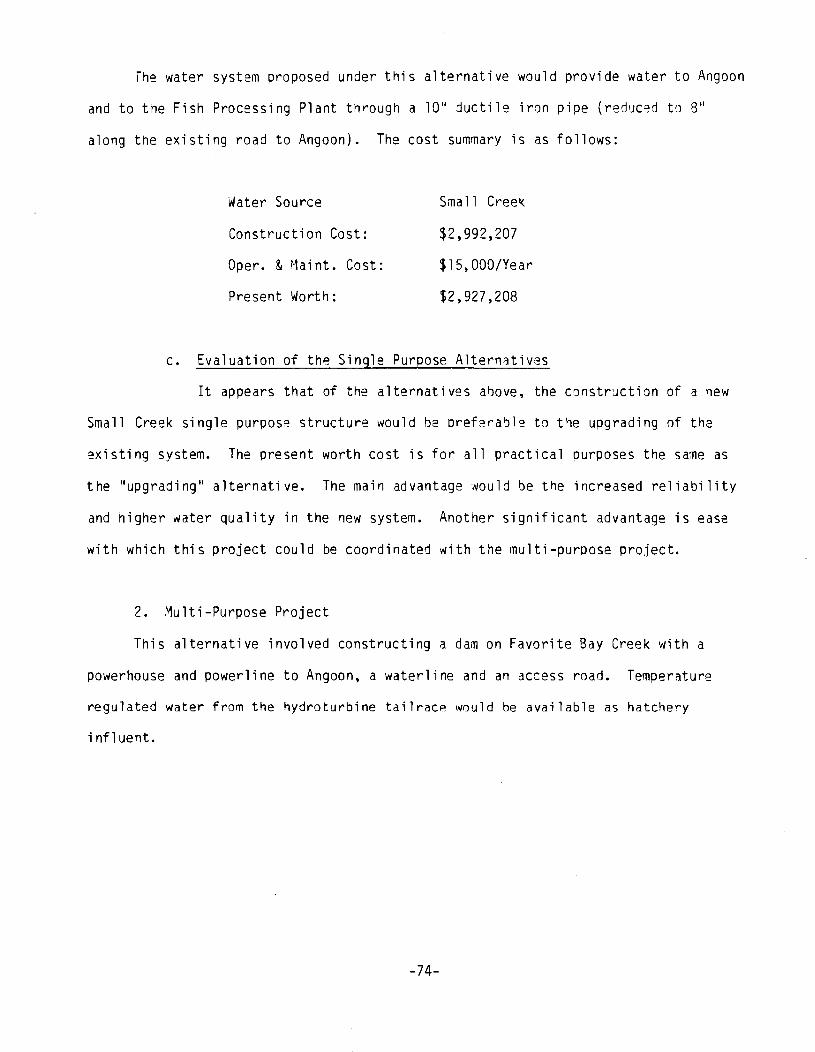
The water system proposed under this alternative would provide water to Angoon
and to the Fish Processing Plant through a 10" ductile iron pipe (red'JCed to 8"
along the existing road to Angoon). The cost summary is as follows:
Water Source
Construction Cost:
Opere & Maint. Cost:
Present Worth:
Small Creek
$2,992,207
$15,OOO/Year
$2,927,208
c. Evaluation of the Single Purpose Alternatives
It appears that of the alternatives above, the constr~ction of a new
Small Creek single purpose structure would be pref2ra~le to t1e upgrading of the
existing system. The present worth cost is for all practical purposes the sa~e as
the "upgrading" alternative. The main advantage 'I%uld be the increased reliability
and higher water quality in the new system. Another significant advantage is ease
with which this project could be coordinated with the multi-purpose project.
2. Multi-Purpose Project
This alternative involved constructing a dam on Favorite Bay Creek with a
powerhouse and powerline to Angoon, a waterline and an access road. Temperature
regulated water from the hydroturbine tailracp. would be available as hatchery
influent.
-74-
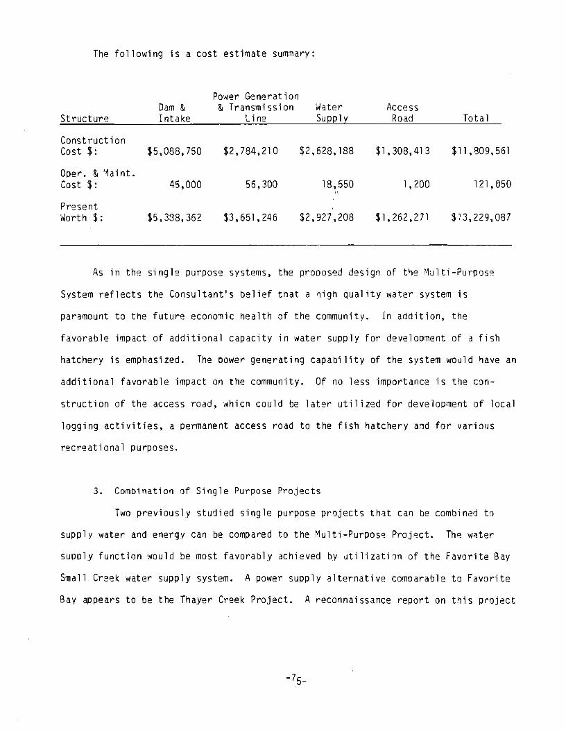
The following is a cost estimate summary:
Power Generation Dam & & Transmission Water Access
Structure Intake Line Suppl~ Road Tota 1
Construction Cost $: $5,088,750 $2,784,210 $2,628,188 $1 ,308,413 $11 ,809,561
Ooer. & ~aint. Cost $: 45,000 56,300 18,550 1,200 121,e>50
,i I
Present Worth $: $5,388,362 $3,651,245 $2,927,208 $1,262,271 $13,229,087
As in the single purpose systems, the proposed design of the Multi-Purpos~
System reflects the Consultant's belief that a ~igh quality water system is
paramount to the future economic health of the community. In addition, the
favorable impact of additional capacity in water supply for development of a fish
hatchery is emphasized. The Dower generating capability of the system would have an
additional favorable impact on the community. Of no less importance is the con-
struction of the access road, which could be later utilized for development of local
logging activities, a permanent access road to the fish hatchery and for various
recre at i ona 1 pu rposes.
3. Combination of Single Purpose Projects
Two previously studied single purpose projects that can be combined to
supply water and energy can be compared to the ~ulti-Purpose Project. The water
supply function would be most favorably achieved by utilization of the Favorite Bay
Small Creek water supply system. A power supply alternative comoarable to Favorite
Bay appears to be the Thayer Creek Project. A reconnaissance report on this project
-75-
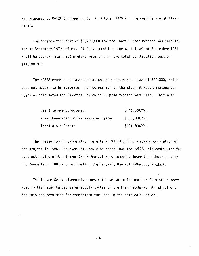
was prepared by HARZA Engineering Co. in October 1979 ~nd t~e results are utilized
herein.
The construction cost of $9,400,000 for t~e Thayer Creek Project was calcula
ted at September 1979 prices. It is assumed that the cost level of September 1981
would be approximately 20% higher, resulting in tne total construction cost of
$11,280,000.
The HARZA report estimated operation and maintenance costs at $40,000, which
does not appear to be adequate. For comparison of the alternatives, maintenance
costs as calculated for Favorite Bay Multi-Purpose Project were used. They are:
Dam & Intake Structure:
Power Generation & Transmission System
Total 0 & M Costs:
$ 45,000/Yr.
$ 56,300/Yr.
$101,300/Yr.
The present worth calculation results in $11,978,552, assuming completion of
the project in 1986. However, it should be noted that the HARZA unit costs used for
cost estimating of the Thayer Creek Project were somewhat lower than those used by
the Consultant (TNH) when estimating the Favorite Bay Multi-Purpose Project.
The Thayer Creek alternative does not have the multi-use benefits of an access
road to the Favorite Bay water supply system or the fish hatchery. An adjustment
for this has been made for comparison purposes in the cost calculation.
-76-
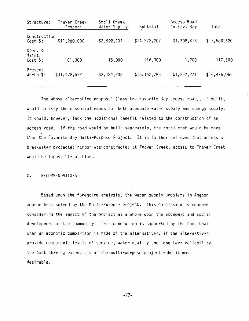
Structure: Thayer Creek Sma 11 Creek A.ccess Road Project Water Supply SUbtotal To Fav. Ba~ Total
Construction Cost $: $11 , 280,000 $2,992,207 $14,272,207 $1,308,413 $15,580,620
Opere & r·1a i nt. Cost $: 101,300 15,000 116,300 1,200 117,500
Present Worth $: $11,978,552 $3,184,233 $15,162,785 $1,262,271 $16,425,056
The above a1ternative proposal (less the Favorite Bay access road), if built,
would satisfy the essential needs for both adequate water supply and energy supply.
It would, however, lack the additional benefit related to the construction of an
access road. If the road would be built separately, the total cost would be more
than the Favorite Bay ~u1ti-Purpose Project. It is further believed that unless a
breakwater Drotected harbor was' constructed at Thayer Creek, aCC2SS to Thayer Cr~ek
would be impossible at ti~es.
C. RECOMMENDATIONS
Based upon the foregoing analysis, the water supply problems in Angoon
appear best solved by the Multi-Purpose project. This conclusion is reached
considering the impact of the project as a whole upon the economic and social
development of the community. This conclusion is supported by the fact that
when an economic comparison is made of the alternatives, if the alternatives
provide comparaole levels of service, water quality and long term reliability,
the cost sharing potentials of the multi-purpose project make it ~ost
desirable.
-77-
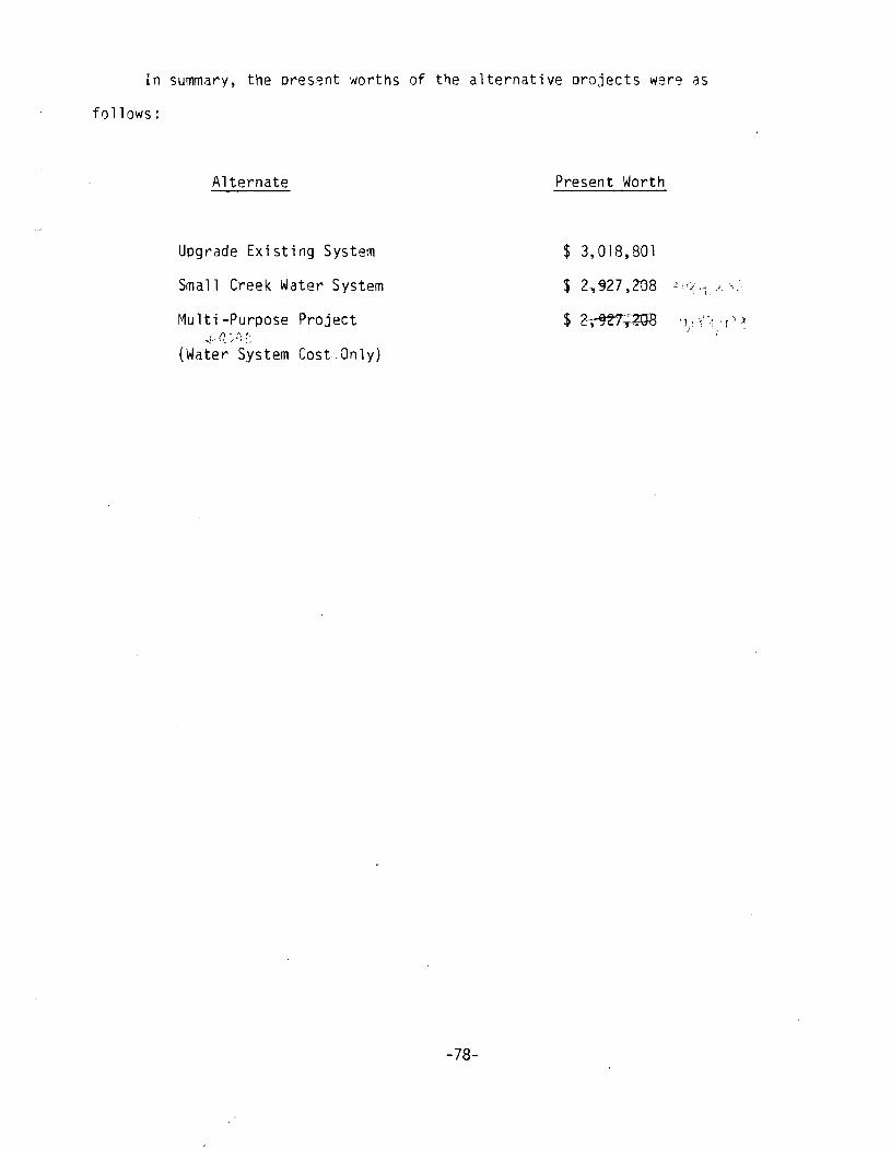
In summary, the oresent worths of the alternative orojects wer~ as
follows:
Alternate Present Worth
Upgrade Existing System $ 3,018,801
Small Creek Water System $ 2.,"927 ,2G8 ~ c:;,~ ) '.
Multi-Purpose Project
(Water System Cost. Only)
-78-
VII. POSSIBLE FUNDING SOURCES & TERMS OF FUNDING
1. INTRODUCTION
Many federal and state agencies have various funding programs and types of
funding available for the Community of Angoon to examine and to pursue for its own
needs.
Possible funding sources: grants, loans and a combination of grants and loans
are available at both the federal and state levels. A fe~ direct appropriatiJns
have been made through the state legislature during the 1981 legislative session.
The following pages are a breakdown of detailed listings of possible funding
sources for single purpose use such as water supply for domestic use and for a
multi-purpose use such as water supply for domestic use and energy supply for the
community of Angoon.
-79-
In conclusion, with the recent budgetary cuts made at the federal level by
Congress in addition to the recent ~ew1y found wealth of the State of Alaska,
funding for either a single or dual purpose project may be better received and
obtained through the State of Alaska.
2. WATER SUPPLY (Single Purpose PrJjects)
Sources of Funds
Alaska Dept. of Env. Conservation
Legislative Appropriation to Community· of Angoon
Legislative Appropriation to Community of Angoon
Farmer's Home Administration
Type of Assistance
Grants
Contact person: Keith Ke Han DEC, Pouch "0" Juneau, AK 99811 (907) 465-2510
Di rect Appropriation Contact person: Dept. of CRA Palmer McCarter Pouch "B" Juneau, AK 99811 (907) 465-4707
Di rect Appropriation
Contact person: Keith Kelton AK DEC Pouch "0" Juneau, AK 99811 (907) 465 -2610
Grants/Loans
Contact person: FmHA, Jim Weidemaier P.O. Box 969 (Rm. 409-Fed. Bldg.) Juneau, AK 99802 (907) 7140
-80-
Comments
Grants of up to 50% to Municipalities for e'1gineering & construction of water supply systems not financed by federal programs. Plans and construction must be approved by DEC.
Funds appropriated under HB 297, 1981 from state tJ local governments based on $525 per capita formula. $277,000 entitlement to Comm. of Angoon.
$500,000 appropriated for for water supply system under HB 50, 1981.
Up to 50% grants for water projects; 5% interest on loans, no upper limit on loan, primarily concerned with residential use of water resource. loans dependant on applicant's qualifications for eligibility for sale of bonds.
Alaska Municipal Bond Bank Authority
AK Dept. of Community & Regional Affairs
U.S. Dept of HUD
3. FISH HATCHERIES
State of Alaska -Fisheries Enhancement Loan Program
Commercial Fisheries & Agricultural Bank (CFAB)
Loans
Contact person: Dave Rose 601 W. 5th Street Suite 325 Anchorage, AK 99501 (907) 274-7365
Grants
Contact person: Pa 1mer ~kCarter Dept. of CRA Pouch B Ju neau, AK 99811 (907) 465-4707
Grants
Contact person: Harry McGee, Dir. 701 "C" Street Box 64 Anchorage, AK 99513 (907) 271-4183
Loan
Contact person: Sharon Traylor Dept. of Commerce & Economic Development Pouch "D" Juneau, AK 99811 (907) 465-2510
Loan
Contact person: John Oaksmith P.O. Box 7018 Ketchikan, AK 99901 907) 225-6615
-81-
Loans currently at about 11.5% interest. Commity of Angoon through ~1-BI3A can sell g.o. bond and d2dicate a portion of local sales tax to payoff de bt.
Rural Development Assistance-$100,000 grants to local gov1t. for local projects.
1. H U D sm a 11 city g ran t s from Community & Planning Dev. Program. This year Congress may give authority to states to administer program. Approx. $1.25M to State of Alaska in form of grants.
2. Indian & Alaska Native Program. Grants to recogni zed Nati ve o rg ani z at ion s • iN ate r project can qualify for $500,000 grant.
Loans of UP to $6.0M for non-profit hatchery program. 30 yr. term, 9.5% interest.
Loan approx. 16%, no upper limit. Can participate ~ith AIDA for loan procedure for fish processing water supply.
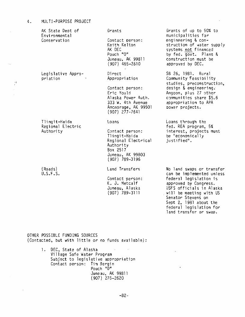
II
4. MULTI-PURPOSE PROJECT
AK State Deot of Envi ranmenta1 Conservation
Legislative Appropriation
Tlingit-Haida Regional Electric Authori ty
(Roads) U.S.F.S.
Grants
Contact person: Ke it h Ke Hon AK DEC Pouch "0" Juneau, AK 99811 (907) 465-2610
Direct Appropri ation
Contact person: Eric You1d Alaska Power Auth. 333 W. 4th Avenue Anchorage, AK 99501 (907) 277-7641
Loans
Contact person: Tl i ng it-Ha ida Regional Electrical Autharity Box 2517 Juneau, AK 99803 ( 907) 789-3196
Land Transfers
Contact person: K. J. Metca 1f Juneau, Alaska (907) 789-3111
OTHER POSSIBLE FUNDING SOURCES (Contacted, but with little or no funds available):
1. DEC, State of Alaska Village Safe Water Program Subject to legislative appropriation Contact oerson: Tim Bergin
Pouch "0" Juneau, AK 99811 (907) 276-2620
-82-
Grants of up to 50% to municipalities for engineering & construction of water supply systems not financed by fed. govt. Plans & construction must be approved by DEC.
SB 26, 1981. Rural Community Feasibility studies, preconstruction, design & engineering; Angoon, plus 27 other communities share $5.6 appropriation to APA power projects.
Loans through the fed. REA program, 5% interest, projects must be "economica1ly justifi ed".
No land swaps or transfer can be implemented unless federal legislation is approved by Congress. USFS officials in Alaska wi 11 be meeti ng with US Senator Stevens on Sept 2, 1981 about the federal legislation for land transfer or swap.
2. Alaska Qenewab1e Resourc= Corporation (Subject to legislative appropriation) Contact person: Phil Hubbard
3. (For access road)
526 Main Street Juneau, Alaska 99311 (907) 465-2620
AK State Dept. of Transportation Local Service Roads & Trails (LSRT) Contact person: Dick Chitty
P.O. Box 3-1000 6860 Glacier Hwy. Juneau, AK 99802 (907) 789-0841
-83-
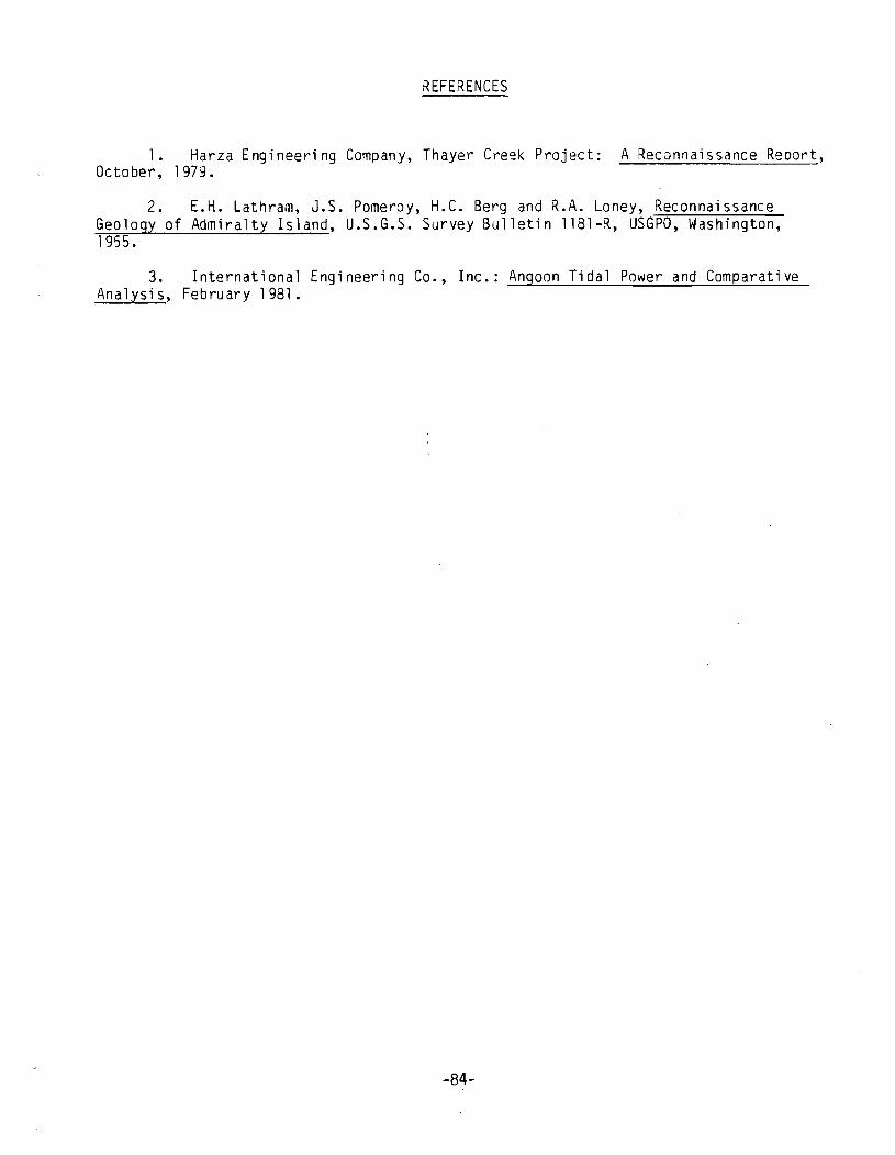
KEFERENCES
1. Harza Engineering Company, Thayer Creek Project: A Reconnaissance Report, October, 1979.
2. E.H. Lathram, J.S. Pomeroy, H.C. Berg and R.A. Loney, Reconnaissance Geology of Admiralty Island, U.S.G.S. Survey Bulletin 1181-~, USGPO, Washington, 1955.
3. International Engineering Co., Inc.: Angoon Tidal Power and Comparative Analysis, February 1981.
-84-
APPENDIX LISTING
APPENDIX A - Standard Agreement for Professional Services Contract.
APPENDIX B - Scope of Services.
APPENDIX C - Layout of Waterline from Small Creek Water Source.
APPENDIX D - Present Worth Value Calculations.

A P PEN 0 I X II All
Standard Agreement for Professional Services Contract

, .!l!:!.ll a I I
\~#JY '~~ STANDARD AGREEMENT F l~
FOR PROFESSIONAL SERVICES LJNTRACT
7hil contract. -MIlch ;s ~11~ctiv~ only if it is.af)f)roved IJv (he Ot.'fJanlllL'Il( of ,'(IIIIII)/srr;](lOII . . ~ iJCCWt:CII (/I~ S(iJlI~ 01 Alaska,
Commerce & Economi c Deve 1 OP'IJ1~!'l.1..--=_61.~ $ kq PQwer f\utho r i ty IWu.'.l/tf'r. rhL' Stall!, at
CanH.CIO'
Tryck, Nyman. and Hayes "";ulinV Ada.,", S .... , o. ", o. SO"
il(.'rt."a I ((.'r, I/lt." Co"tracr:
elfV 51.a','
740 I Street, ~A""l .. -'."-. ""'Qu~ .. o::'" .. ~, ~L..c::-:.~",=-=.;:iN~u,="U~"=-'""---- --.. -_. -
99501
013756
--_._---._ ........ -._--_ .. - ------O.IJ"'o'''mm .... e' °r'ce & Economi c Develo ment I\ltn: 0,,,,.,,,,\.,,,,, h _--=I..;;.;;.;=,;....:...;;;....~~~~~~ ______ ~.;......;;;....;...; ______ ~"--_ __~~aska Power Aut or; ty ______ _ "".;Ilroo AClCI'"'
333 West 4th Ayenue. Suite 31. An.ch.o.r:a.ge._Al ska ____ 99501 c ONTRACTOR STATE
--""':'""':":-----=.....::.:..:....:...;.;.,;..;".;:;..~~--------+------...... -----... --N .. ne.' Fi,na (']0., •• ,,, .. ,'" or J\c,I'!ncv
Tryck, Nyman and Hayes ___ A 1~ .. s-.~~_.PQ~"I~!" _Auth~ . ~;i~""'I"'1! nl l.nrlilvinfl 011 ... ",
~ __ ..:.F..:.r-=a.!.!n=.k-,N:...:..L:.:::a:.:.n~---_---_-----t""::r.-iLt,-Y.QY-,-' d=--_ T;t'. Till.
. .ar.u~!LJ..e.an .... 5 __ _
Partner Executive Director De ut Commissioner APPROVAL BY TIE DEPAATM:NT OF ACiMNISTRATlON
NOTICE I This contract has no effect except as an offer bV the Contractor unril it is approved by the Denartment of Auminiscratic -.. ------r:~_'O! ______ . ___ _ T.,ped 00 ~ri"'ed N.,.,e of Au,horl.ln, Offlciol
APPENDIX A
-"'Ie" 1. Dean ........
1.1. lit .... COIdrecllftd 1CII*'dC-. ~ olne.'· IIIOeM Ihe per~ whO !ions IhiS con'rlCl on behlll! 01 the Del)(Wlml!nl and includes. succ.ssor or II.IIho,.. I .......... .
1.2 M~ •• __ me ~ lor whiCft IlIis cantrect Is 10 be l)4Ir'OImod anc:I'OI whlcll IhO CCllllyono Ollieer acled on So9lW10 tnI, controel
Anlel.:. "'.pee, ......... "e""l. 2.1 TIle ~ ..., iNoect. in die ,...,., Melli I.""""" times it considers lODfooriale. n. Ihe Contraclor'S ';jCI'ilies and activities unoer 'hiS contracl.
2.2 The Can_Clor ... ".. poor ... lftd.,..,er r-cons in ,he manner anc:I .. Ihe 'imes the Qeunl'm'!fI' IOOsonably ICQUlte3
Anlele~. S"'e Sen4 Ha .......
The eon.8Clor ___ ifIcIermiIy and I'Ia'd INI_ lhe Sllie. ils olllc:llfs. lQenlS lind emoloy ••• hlV"""'s "0m 'inhoijly 01 rilly nnll 0(" o. k,mJ. inCluOiIlI,Il:OSIS allo a-oons ••. 100 on ICCGunI 0/ Illy and "'. ecttana or dIIims 0' lIlY C""lClllr ..... 1.0..,." .ltsulllnQ 'rOlft onjune. 0/ r'r'"""I"~ ~"s':linod by n"y [,'"'!:Of, 0' pa.sons or p.oovr'y :.'O/nQ 'rom ,IS ~ 'OIINIICO 011'" contreclin Illy w~ w~, '

A P PEN 0 I X 118 11
Scope of Services
'I I
Appendix B
Art i c 1 e 8-1. Scope of Servi ces :
The first objective of these services is to estimate the water supply benefits of a dual purpose water resource development project at Favorite Bay. The method of estimating the water supply benefits consists of determining the lowest cost way of supplying the water by means of a single purpose water supply project. The costs that would otherwise be incurred for this water supply project are taken as an estimate of water supply benefits of the dual purpose Favorite Bay Project.
In assessing the least cost single purpose water supply project, at least ~Q plans will be analyzed. Each plan must satisfy the following basic assumptions:
(1) provide adequate flows for fire fighting in Angoon;·~ (2) provide adequate domestic water supply; and-(3) provide adequate flows to satisfy the needs of a fish processing plant y
currently under design by Angoon.
Each plan shall include:
(1)
(2) (3)
a narrative describing the physical layout, construction and operation of the facil ity; an estimate of the capital and operating costs; and the summatjon· of discounted yearly costS--Qver the economic life of the projec~ (5~ yea!s). A d~scount rate.of 3 ~ercent shall be used in the. ~ analysls W'rth--an assumptlon of zero lnfTatlo".. (Refer to Power Authorlty ~ Sample Cost Calculation)
Each plan will include necessary waterlines to serve the community, including a storage tank, if reasonably required to meet fire demand standards. Water Supply Alternative No.1 will analyze a water supply line generally following the routing shown in Figure IV-I from the report entitled "Angoon Hatchery Concepts" prepared by TNH on September 10, 1980. This line would run from Favorite Creek to Angoon. Water Supply Alternative No.2 will analyze a water line crossing Kootznoowoo Arm and supplied from a source identified as the stream supplied by the small lake in Sec. 19, TSOS, R68E, Copper River Meridian. Other possible alternates such as tapping the next stream east of the alternate stream would also be examined if necessary to provide adequate volume to meet the basic assumptions identified in paragraph 1 of this scope of services.
The field data collected for this study will include barometric level profiles from the proposed water supply source to the distribution system and to the fish processing site.
In order to accomplish the study, a synthetic hydrograph will be developed for eacQ stream. In addition, it is anticipated that while the study is progressing, additional stream gaugings of the streams will be obtained in a continuing effort to improve the synthetic hdyrographs for streams in the Angoon area.
The Alaska Power Authority will make available to THN any previous related studies that would bear on this alternative analysis study.
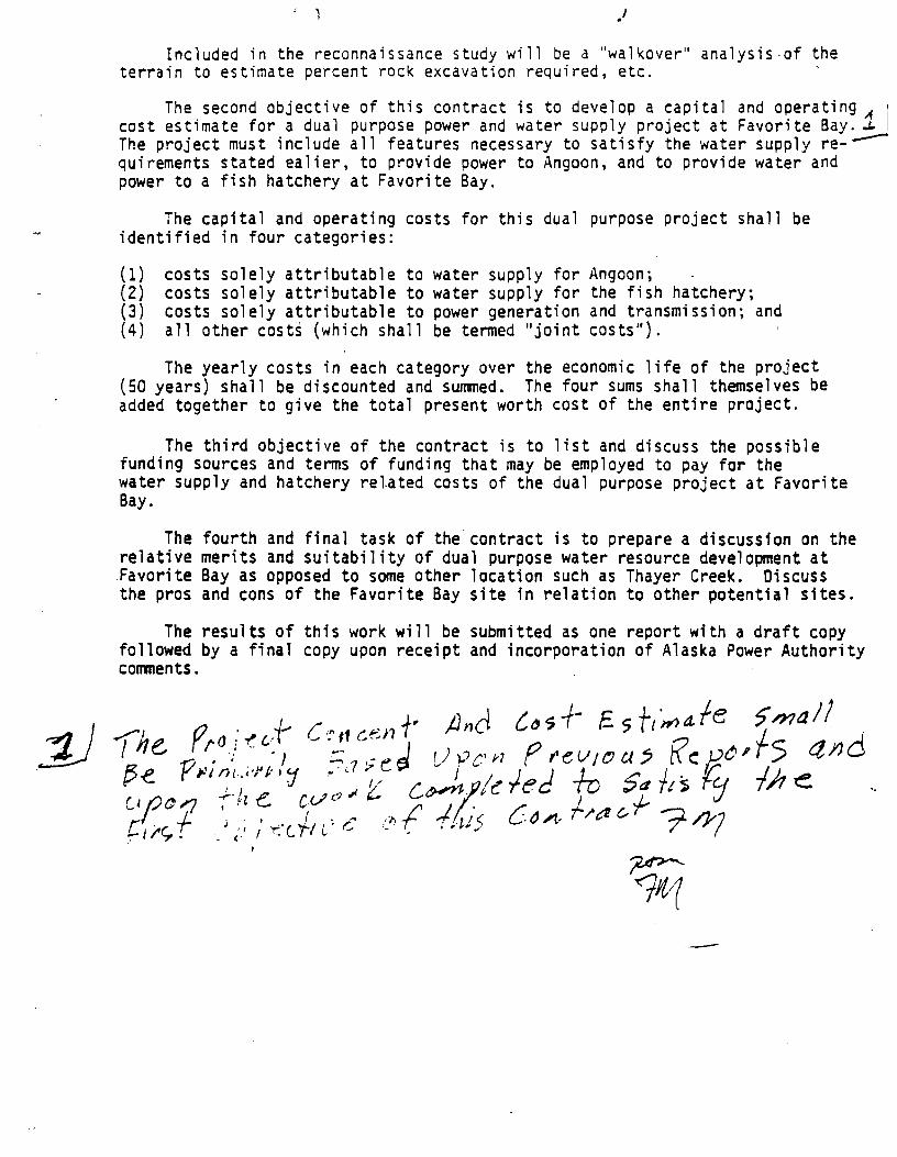
.'
Included in the reconnaissance study will be a "walkover" analysis-of the terrain to estimate percent rock excavation required, etc.
The second objective of this contract is to develop a capital and operating 1 I cost estimate for a dual purpose power and water supply project at Favorite Bay~ The project must include all features necessary to satisfy the water supply requirements stated ealier, to provide power to Angoon, and to provide water and power to a fish hatchery at Favorite Bay.
The capital and operating costs for this dual purpose project shall be identified in four categories:
(1) costs solely attributable to water supply for Angoon; (2) costs solely attributable to water supply for the fish hatchery; (3) costs solely attributable to power generation and transmission; and (4) al1 other costs (which shall be termed "joint costs").
The yearly costs in each category over the economic life of the project (50 years) shall be discounted and summed. The four sums shall themselves be added together to give the total present worth cost of the entire project.
The third objective of the contract is to list and discuss the possible funding sources and terms of funding that may be employed to pay for the water supply and hatchery related costs of the dual purpose project at Favorite Bay.
The fourth and final task of the contract is to prepare a discussfon on the relative merits and suitability of dual purpose water resource development at Favorite Bay as opposed to some other location such as Thayer Creek. Discuss the pros and cons of the Favorite Bay site in relation to other potential sites.
The results of this work will be submitted as one report with a draft copy followed by a final copy upon receipt and incorporation of Alaska Power Authority corrments.
-

A P PEN 0 I X II C II
Plan - Profile for Small Creek Water
System
3 Q"tt.{ S" z.J "D (' 0.\ ~ \ \f\. ~
P, ~\OCIV'. w~-c/ svrrl~ Fo-.vor;tc., Cree. K Ylc.~ ~~wt
'p,.j: I~

A P PEN 0 I X II 0 II
Present Worth Calculations
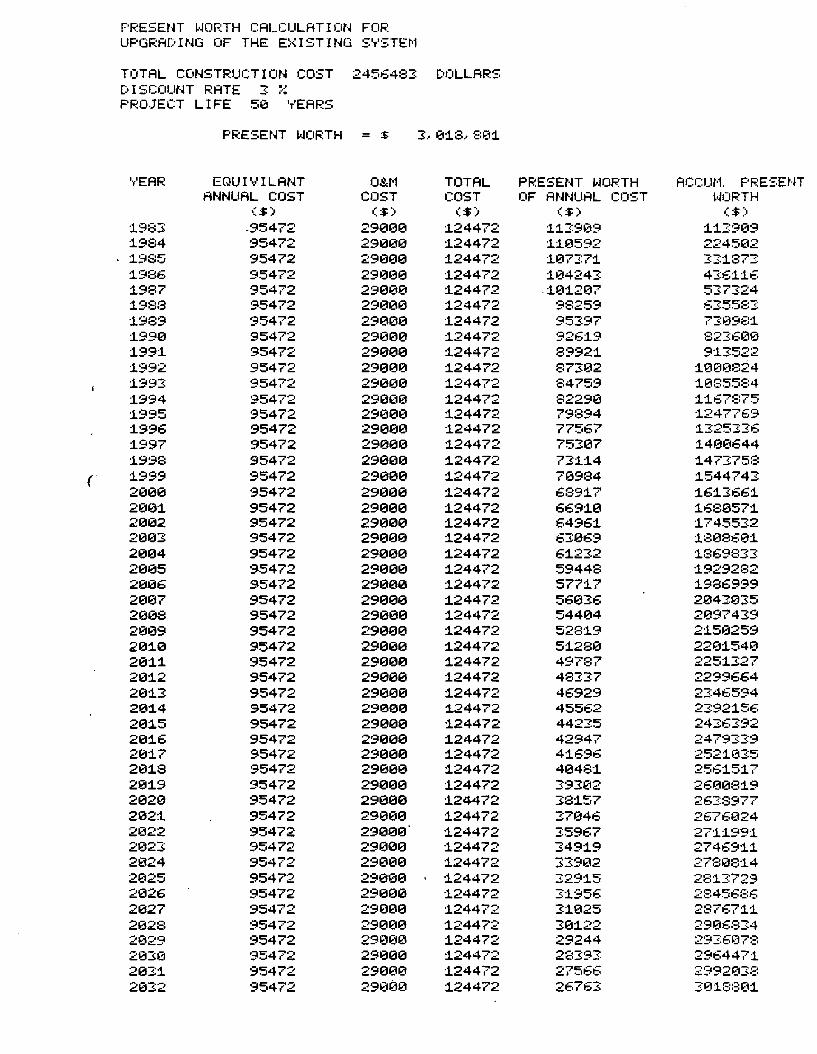
F'F.:ESEtn wornH CALCULATION FOF': UPGRA[:' I NG OF THE E::<ISTING S'T'STEI'1
TOTAL CONSTRUCTION COST 2456483: [')OLLARS [:'ISCOUNT RATE
.., ".' .;:. ...• PRO.JECT LIFE 510 'T'EARS
PRESENT WOF':TH = :$ 3, 1211.8., 81211.
VEAR EQU I V I LAt·n O&r'1 TOTAL PRESENT WORTH ACCUt'1. PF.:ESENT ANNUAL COST COST COST OF ANNUAL COST ~,JOFnH
($) ($) ($) ($) ($)
1.983: .95472 2912112113 1.24472 1.1.3:91219 1.1.3:909 1.984 95472 2913121121 1.24472 1.1.13592 2245~12
1985 95472 29121121121 1.24472 1.073:71. 3:31.87:! 1.986 95472 29121121121 1.24472 1.1214243 43:61.1.6 1.987 95472 291210121 1.24472 ·1.1211.21217 537324 1.988 95472 2901210 1.24472 98259 6355:::3: :1989 95472 29121121121 1.24472 953:97 73:09:::1 1.99121 95472 29012113 1.24472 9261.9 823:600 1.991. 95472 29131313 1.24472 89921. 913:522 :1992 95472 291300 1.24472 873:102 1.0013824 1.993: 95472 29131313 1.24472 84759 1.085584 1.994 95472 29121013 1.24472 82290 :1.:1.67:::75 1.995 95472 291313121 1.24472 79894 :1247769 1.996 95472 2913013 1.24472 77567 :13253:36 1.997 95472 29012113 1.24472 7531217 1.4e€1644 1.998 95472 29131313 1.24472 731.1.4 :1.473:758
( 1.999 95472 2912112113 1.24472 70984 1.544743 2013121 95472 29131313 1.24472 689:17 1.61.3661. 21301. 95472 29131313 1.24472 6691.121 1.68121571. 2131212 95472 29131313 1.24472 64961. 1.745532 213133: 95472 291313'21 1.24472 63:1369 1.808601. 213134 95472 29131313 1.24472 61.232 :1869833 2121135 95472 29131313 1.24472 59448 :1929282 2131216 95472 29131313 1.24472 5771.7 1.986999 2121137 95472 29131313 1.24472 56133:6 21214:203:5 212108 95472 29131313 1.24472 544134 21219743:9 213139 95472 291312113 1.24472 5281.9 21.5~3259
2131.121 95472 291312113 1.24472 51.28121 22131.540 2131.1. 95472 29131313 1.24472 49787 2251327 21211.2 95472 29131313 1.24472 483:37 2299664 21211.3 95472 2913121121 1.24472 46929 23:46594 201.4 95472 290121121 1.24472 45562 2392:156 2121:15 95472 2913121121 1.24472 44235 243:6392 2121:16 95472 29121121121 :124472 42947 2479339 20:17 95472 29121121121 :124472 41.696 2521.035 213:18 95472 2912113121 1.24472 41348:1 2561.51.7 213:19 95472 29131313 1.24472 393:1212 26121081.9 21320 95472 2913121121 1.24472 381.57 263:8977 21212:1 95472 291211313 1.24472 3:7046 2676024 21322 95472 29121121121 1.24472 3:5967 271.1.991. 21323 95472 291211313 1.24472 349:19 274691.1. 21324 95472 29131313 1.24472 33902 27f::e81.4 2025 95472 291211013 :124472 3:29:15 28:13:729 2026 95472 29013121 1.24472 3:1956 2:3456::::6 2027 95472 291300 1.24472 31.£125 28767:1.~
2028 95472 29000 :124472 30:122 29136834 2029 95472 2913121121 1.24472 29244 293:607:3 21213:0 95472 291000 1.24472 2c::l93: 2964471. 2031. 95472 29131313 1.24472 .-.,1:'" .- .-.::., -_11:-1:1 2992~1J:::
2032 95472 2912100 :124472 26763 31211.::::::131.
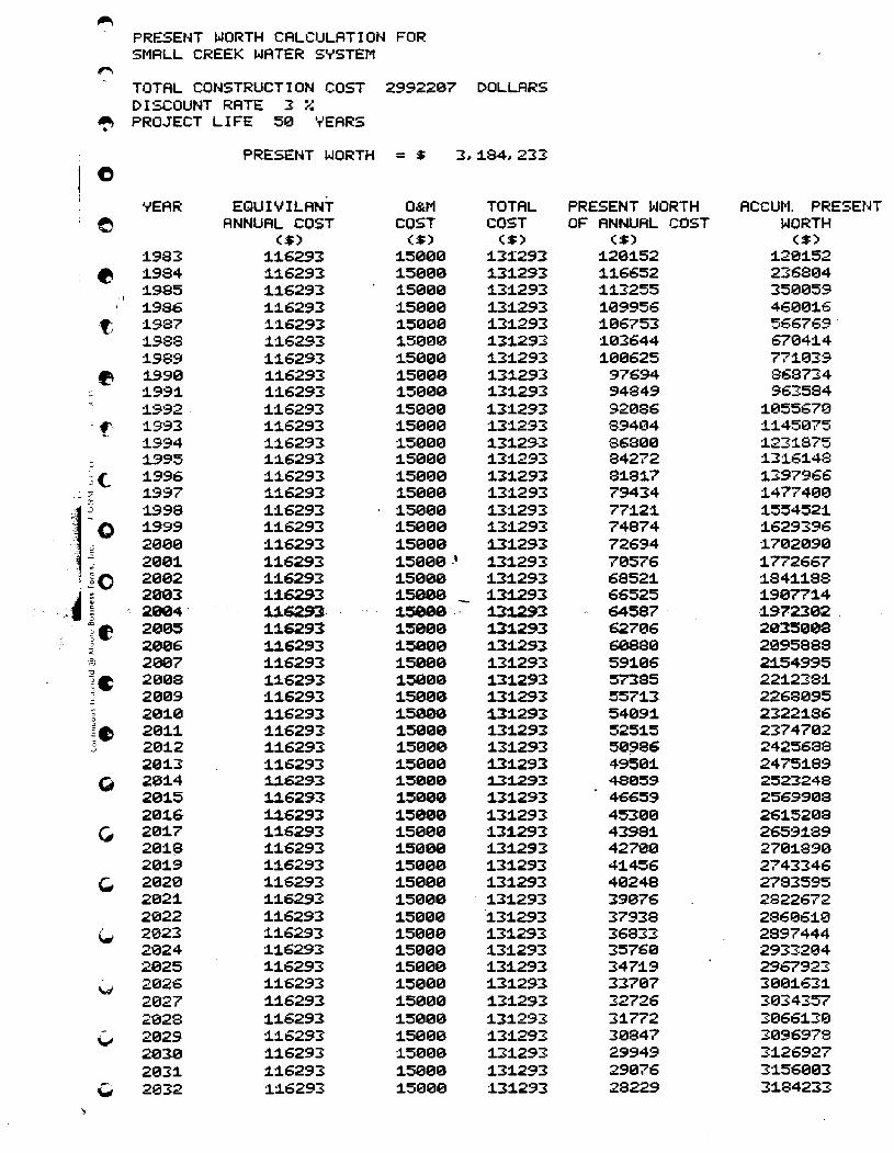
".., - PRESENT WORTH CALCULATION FOR
St'1ALL CREEK WATER SYSTEM ,..., ,
TOTAL CONSTRUCTION COST 2992207 DOLLARS DISCOUNT RATE :3 ::.-~
~ PROJECT LIFE 5'.21 ''''EARS
PRESENT WORTH = $ 3~1.84~233
e YEAR EQUIVILANT O&M TOTAL PRESENT WORTH ACCUM. PRESENT
e ANNUAL COST COST COST OF ANNUAL COST WORTH ($) ($) ($) ($) ($)
1.983 1.1.6293 1.5'.21'.21'.21 1.3:1293 1.2'.211.52 1.281.52 e 1.984 1.1.6293 1.5'.21'.210 1.31.293 1.1.6652 2368'.214
1.985 1.1.6293 1.5'.21'.21'.21 1.31.293 1.1.3255 35'.21'.2159 'I
1.986 1.1.6293 1.5'.21'.21'.21 1.31.293 1.'.219956 46'.21'.211.6 t:. 1.987 1.1.6293 1.5'.21'.21'.21 1.31.293 1.06753 566769'
1.988 1.1.6293 1.5'.2100 1.31.293 1.'.213644 67041.4 1..989 1.1.6293 1.5'.21'.21'.21 1.31.293 1.0'.21625 771.039
~ 1.990 1.1.6293 1.5000 1.31.293 97694 868734 : 1.991. 1.1.6293 1.5000 1.31.293 94849 963584
1.992· 1.1.6293 1.5'.21'.21'.21 1.31.293 92086 1.055670 . f" 1.993 1.1.6293 1.5'.21'.21'.21 1.3:1293 89404 1.1.45075
1.994 :1:16293 1.50'.21'.21 1.31.293 868'.21'.21 1.231.875 :: :1995 1.1.62.93 1.50'.21'.21 1.31.293 84272 1.31.61.48 ~(. 1.996 :1:16293 1.5'.21'.210 1.31.293 81.81.7 1.397966
-~ ~ 1.997 1.1.6293 1.5'.21'.210 1.31.293 79434 1.4774'.21'.21
r 1.9.98 1.1.6293 1.5'.21'.210 1.31.2.93 771.21. 1.554521. : "0 1.999 1.1.6293 1.5'.2100 1.31.293 74874 1.629396 -.
. v 2'.21'.21'.21 1.1.62.93 1.50'.210 1.31.293 72694 1.7'.21209'.21 2'.21'.211. 1.1.6293 1.50'.210,\ 1.31.293 70576 1.772667
, ~O 2'.21'.212 1.1.6293 1.50'.210 1.31.293 68521. 1.841.1.88 " 0 ,~
2093 1.:16293 1.5000 1.3:1293 66525 1.9'.21771.4 4~ ,,,. '3 2004 U6293· :15890 1.3~3 64587 1.972392 ~e 2'.2195 1.:16291 1.5990 1.31.293 62706 2035'.2198 '5 -
2'.2196 U6293 1.5099 1.31.293 6e8se 2e9588S 0
:E g) 29'.217 1.1.6293 1.5000 1.3:1293 591.06 2:154995 ...,
200S 1.:16293 1.5090 1.31.293 S7385 221.2381. ~C " 2009 1.1.6293 1.5990 1.31.293 5571.3 2268'.2195 0 291.'.21 1.1.6293 1.5000 1.31.293 54091. 23221.86 0
~e 291.1. 1.1.6293 1.5090 1.31.293 5251.5 2374792 c 2'.211.2 1.1.6293 1.5990 1.31.293 59986 2425688 '-'
201.3 1.1.6293 1.5'.2190 1.31.293 49501. 24751.89 G; 201.4 U6293 1.5000 :13j.293 48059 2523248
201.5 :1:16293 1.5000 1.31.293 466:59 2569908 201.6 :1:16293 :15900 1.3:1293 453'.210 261.52'.218
C, 201.7 1.1.6293 1.5'.2109 1.31.293 43981. 26591.89 2e1.~ 1.1.6293 1.5900 1.31.293 42789 2701.890 2'.211.9 1.:16293 1.50'.210 1.31.293 41.456 2743346
~ 202'.21 1.1.6293 1.590'.21 1.31.293 4'.21248 2783595 2021. 1.1.6293 1.5090 1.31.293 39076 2822672 2022 1.1.6293 1.50'.21'.21 1.31.293 37938 286061.0
i..- 2023 1.1.6293 1.5'.21'.21'.21 1.3:1293 36S33 2897444 2'.2124 :11.6293 1.5099 1.31.293 35760 2933204 2'.2125 1.1.6293 1.5990 1.3:1293 3471.9 2967923
'oN 2026 1.1.6293 1.5'.21'.219 1.31.293 337'.217 30'.211.631. 2027 1.1.6293 1.5999 1.31.293 32726 3'.2134357 2'.2128 1.1.6293 1.5999 1.31.293 31.772 30661.310
v 202.9 1.1.6293 1.5'.21'.210 1.31.293 3'.21847 3'.2196978 2'.2139 1.1.6293 :15'.21'.21'.21 1.31.293 29949 31.26927 2'.2131. 1.1.6293 1.59'.210 1.31.293 29976 3:1560'.213
" 2'.2132 1.:16293 1.5'.21'.210 1.31.293 28229 31.84233
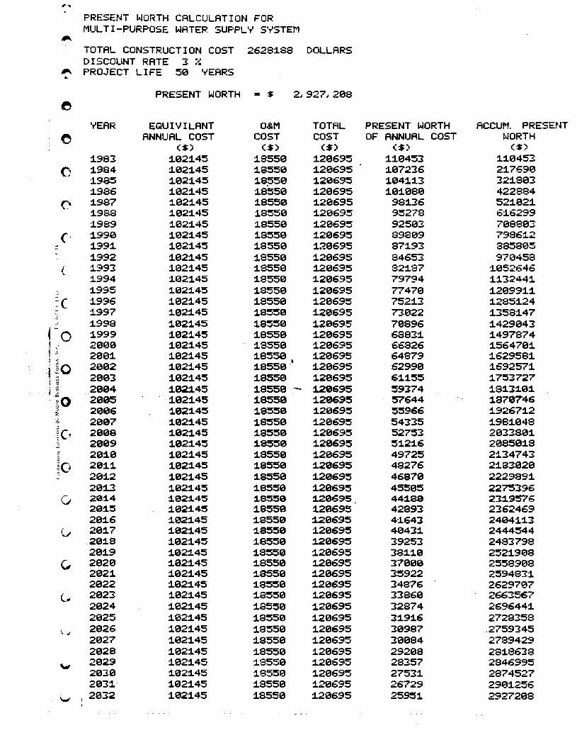
' ... PRESENT WORTH CALCULATION FOR MUL TI-PURPOSE WATER SUPPL'-I S'-ISTEM
~
TOTAL CONSTRUCTION COST 2628:1.88 DOLLARS DISCOUNT RATE 3 ;-;
~ PROJECT LIFE 59 "'EARS ~
PRESENT WORTH = :$ 2,927,298 e
'-lEAR EQUIVILANT 08.M TOTAL PRESENT WORTH ACCUM. PRESENT 0 ANNUAL COST COST COST OF ANNUAL COST l<lORTH
($) ($) ($) ($) ($)
:1.983 :1.92:1.45 1.8559 1.29695 1.1.9453 1.1.9453
0 1.984 1.921.45 1.8559 1.29695 1.97236 21.76913 1.985 1.921.45 1.8~50 1.29695 1.041.1.3 321.893 1.3/36 1.021.45 1.8559 1.20695 1.91.0813 422884
0 1.987 1.021.45 1.8550 1.20695 981.36 521.021. 1.988 1.021.45 1.8550 1.29695 95278 61.6299 1.989 1.921.45 1.8559 1.29695 92503 798803
C 1.990 1.921.45 1.8559 1.20695 89899 79861.2 - 1.991. 1.921.45 1.8550 1.20695 871.93 885895 -
1.992 1.021.45 1.8559 1.20695 84653 97'0458 { 1.993 1.'021.45 1.8550 1.29695 821.87 1.952646
1.994 1.021.45 1.8550 1.20695 79794 1.1.32441. : 1.995 1.921.45 1.8559 1.20695 77479 1.29991.1. ::c 1.996 1.021.45 1.8550 1.20695 7521.3 1.2851.24
1.997 1.021.45 1.8550 1.20695 73922 1.3581.47 J 1.998 1.921.45 1.8559 1.20695 79896 1.429943 rO 1.999 1.021.45 1.8550 1.20695 68831. 1.497874
1 .; 2009 1.021.45 1.8550 1.20695 66826 1.564701. 1 -= 29131. 1.021.45 ~:;:.\ 1.20695 64879 1.629581. 1 g·O 2002 1.921.45 1.20695 62999 1.692571. ) ~ 2093 1.921.45 1.9550 1.29695 61.1.55 1.753727 i ~
H 2004 1.02j.45 1.8550 j.,20695 59374 1.81.31.91. , io 2005 1.021.45 1.8550 1.20695 57644 1.870746
0 2006 1.021.45 1.8550 1.29695 55966 1.92671.2 :::; g) 2907 1.021.45 1.8550 1.20695 54335 1.981.048
tG 2009 1.021.45 1.8550 1.29695 52753 2033801. 2009 1.021.45 1.8550 1.20695 51.21.6 208501.8
15 201.0 1.021.45 1.8550 1.29695 49725 21.34743 ~O 201.1. 1.021.45 1.8559 1.20695 48276 21.831320 0 201.2 1.921.45 1.8550 1.20695 46870 2229991. 'J
20:13 1.921.45 1.8550 1.20695 45505 2275396 0 20:1.4 :1.02:1.45 :1.8550 1.20695 441.80 231.9576
201.5 1.021.45 1.8550 1.20695 42893 2362469 291.6 1.021.45 1.8550 1.20695 4:1643 2494:11.3
Co 201.7 1.921.45 1.8550 :129695 413431. 2444544 201.8 1.021.45 :19550 1.20695 39253 2483798 291.9 1.021.45 1.8550 :120695 381.1.9 2521.9138
(, 2029 1.021.45 1.8550 1.20695 37090 2558908 2921. :1.021.45 1.8550 1.20695 35922 2594831. 2022 1.021.45 1.8550 1.20~95 34876 2629707
C. 2023 1.021.45 1.8550 1.20695 33860 2663567 2924 1.021.45 1.8550 1.20695 32874 2696441. 2025 1.021.45 1.8550 1.20695 31.91.6 2728358
\, .I 2026 1.021.45 1.8550 1.20695 30987 .2759345 2027 1.021.45 1.8550 1.20695 30084 2789429 2028 1.021.45 1.8550 1.20695 29208 281.8638
""'" 2029 1.021.45 1.8550 1.20695 28357 2846995 2030 1.021.45 1.8550 1.20695 27531. 2874527 2031.' 1.021.45 1.8550 1.29695 26729 29131.256
I...t' 2032 1.021.45 1.8550 1.20695 25951. 2927298
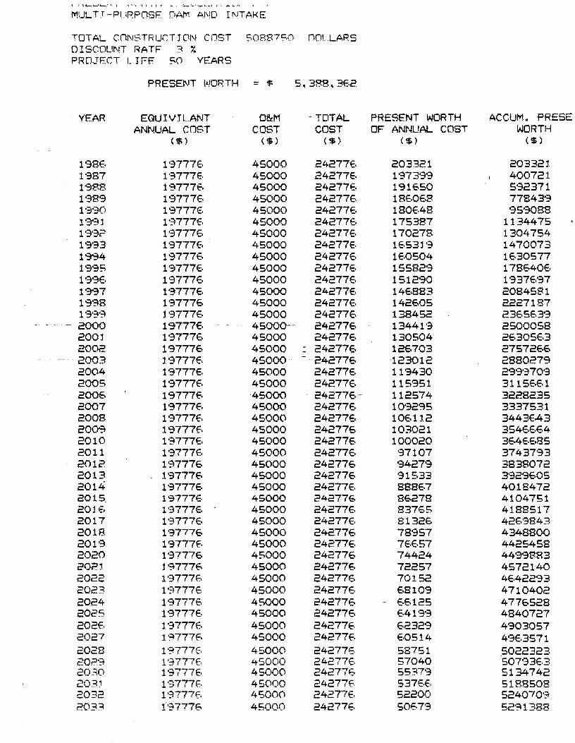
J " ......... ''-"1'. I \'.\ 't > i j f ""1 ::-'\"\_'1._< f 1 ..... \..·. '.
MULTr-PURPC1SF DAM AND INTAKE
TOTAL CONSTRUCTl~~ COST S08B7S0 DOLLARS 01 SCOLtl'H RA TF ;:\ OJ
I.
PRO~TF.CT L. IFE SO YEARS
PRESENT t"!ORTH = $ 5.388.3E.2
YEAR EGUIVJL.ANT O&M - TOTAL PRESENT WORTH ACCUM. FRESE ANNUAL COST COST COST OF ANNUAL COST WORTH
($ ) ($ ) ($) ($ ) ($)
l'38E. l'3777E, 45000 24277E, 203321 20332:1. 1'387 l'3777E, 45000 24277E, 1973'39 400721 1'988 19777fi:, 45000 24277E, 191650 5'32371 1'389 l'":]777E, 45000 24277E. 18E,OE.8 77843'3 1'":]'30 19777E, 45000 24277E. 180E.48 95'3088 19'31 l':;l777E, 45000 24277e. 175387 1134475 1'3'32 l'3777E, 45000 24277E, 170278 1304754 1'3'33 19777€. 45000 24277E, lE,531'3 1470073 19'94 19777E, 45000 242776 lE,0504 1630577 19'35 19777E. 45000 242776 15582'3 178640E. 1'3'36 l'3777E· 45000 24277E. 1512'30 1937E.'37 1'~37 l'3777E. 45000 24277E. 146883 2084581 1998 l'3777E, 45000 24277E. 142605 2227187 1'3'3'~ 197776 45000 242776 138452 236SE,3'3 2000 197776 45000-- 242776 13441'3 2500058 2001 19777E, 45000 24277E. 130504 2E,305E,3 2002 197776 45000 - 242776 12€,703 2757266 -
-- 2003 l.'3777E. 45000-- - 242776 -123012 2880279 2004 19777E. 45000 24277E, 119430 29'3'370'3 2005 l'3777E, 45000 242776 115951 3115E.E.l 200E, 197776 -45000 24277E.- 112574 3228235 2007 l'3777E, 45000 24277E, 10'32'35 3337531 2008 19777E. 45000 24277E, 106112 3443E,43 2009 19777E. 45000 242776 103021 3546E.64 2010 l'3777E, 45000 242776 100020 364E.E.$35 2011 1·3777E. 45000 24277E, 97107 37437'33 2012 1'37776 45000 242776 9427'3 3838072 2013 19777€- 45000 242776 91533 3'329605 2014 l'3777E, 45000 24277E. 8B8E,7 4018472 2015. lS777E. 45000 242776 86278 4104751 20l E. l'3777E. 45000 24277E. 83765 4188517 2017 l'3777E. 45000 24277E, 8132E. 42E,9843 2018 197776 45000 242776 78'357 4348800 201'3 19777E, 45000 24277E. 7E.6S7 4425458 2020 l'3777E, 45000 242776 74424 44'3"3883 2021 1 9777f-. 45000 24277e. 72257 4572140 2022 197775 45000 24277E, 70152 4E.422'33 2023 l"777E. 45000 24277E, 68109 4710402 2024 19777E. 45000 242776 - E.6125 4776528 2025 197776 45000 242776 E.4199 4840727 202E. l'3777E. 45000 24277E. E.2329 4903057 2027 l'~777E. 45000 24277E, 60514 49E,3571 2028 l"777E. 45000 24277E, 58751 5022323 20,::)'3 l'3777E. 45000 24277E. 57040 507'33E.3 2030 19777E. 45000 24277e. 5537'3 5134742 203:1 1'3777E. 45000 24277E. 537E.E. 5188508 2032 l'?!777E. 45000 24277E. 52200 524070'?! 203:=l 197776 45000 242776 5067'3 52'~1388
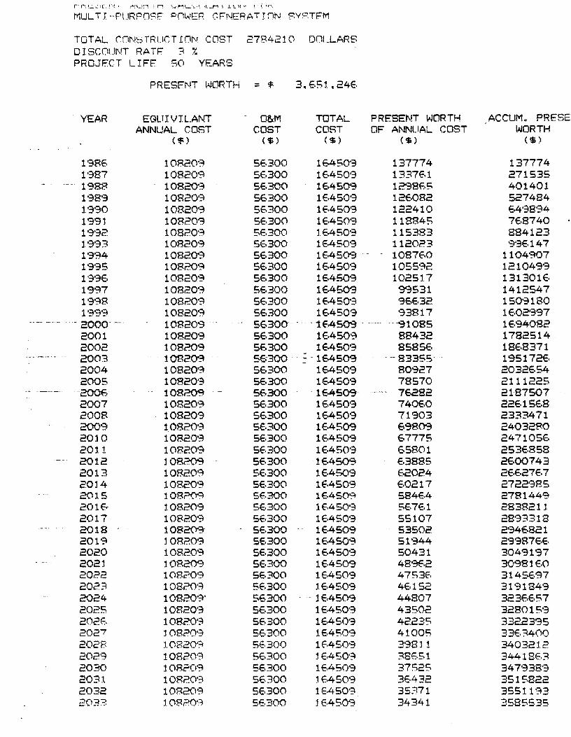
r" i\ C. ~:-)I.:-: l'~ f V··!\ ... Il''<:, i r: \ .. , ML.o'._,I. il._M I J. '- II '\~ ! '.. tr,,\
MUL T I --PlJRPOSF °(iWER GFNERATTON SV~':::TFM
TOTAL (ONbTRUCTION. COST 2784210 DOLLARS DISCOUNT RATF 3 .,
i.
PROJFCT LIFE SO YEARS
PRESENT I;JORTH = $ 3. E.S:I .• 24E.
YEAR EGLlIVIl.ANT O&M TOTAL PRESENT WORTH ACCUMN PRESE ANNUAL CaST COST COST OF A"~NUAL COST I.-JORTH
( $) ($ ) ($) ('$ ) ($)
19BE. 10B20'3 5E,300 lE450'3 137774 137774 1'387 10820';\ 5E.300 lE,4509 1337E.l 271535 1'388 1082()<3 5E,300 lE.45cr3 12"38f..5 401401 198'3 10820';\ 56300 1EA50'3 12E,082 527484 j'3'30 10820'3 5E.300 lE,4509 122410 64'38'34-1991 10820'3 SE.300 1EAS09 118845 7E,8740 19'32 10820'3 SE.300 lE,4S0'3 115383 884123 1'3'33 10820'3 SE.300 1EA50'3 112023 9'3E,147 1'3'34 10820'3 5E.300 1E.450'3 1087(;0 1104907 1995 10820'3 5E.300 lEA50'3 1055'32 121049'3 1·3'3E. 10820'3 5E.300 164?0'3 1025:1.7 131301E. 19';\7 10820'3 56300 lEA50'3 9'3531 1412547 19':'8 108209 5E.300 16450'3 96632 150'3180 1'39'3 108209 56300 lEA509 '33817 lE.02997
-. - -~--- - 2000· 108209 -- 56300- - ---1EA509 -~1085 1694082 2001 108209 56300 1EA50'3 88432 1782514 _ 2002 108209 5E.300 lEA50'3 85856 18E.8371 2003 - 10820'3 5E;300 16450'3 -83355· 195172€. 2004 10820'3 5E,300 164509 80927 20 32E.S4 200S 10820'3 5E,300 lEAS09 78570 2111225
.~ ---~-". -200E, 108?0'9 56300· 1E.i+509 7E.2S2 2187507 2007 10820'3 5E.300 164509 74060 22E.1SE,8 2008 108209 56300 164509 71903 2333471 2003 10B209 5E.300 1EA509 898M 24032FO 2010 10820'3 5E.300 lE.4S0'3 67775 247105E. 2011 108209 5E.300 16450'3 65801 253E.858 2012 108209 56300 lE.4S09 E.3885 2E.OO743 2013 10820'3 SE.300 1E,4509 62024 2E.E,27E,7 2014 10820'3 5E.300 lE.4509 E.0217 2722985 2015 108?('l-3 56300 1€A5~ 584€A 2781449 201€< 1.0820'3 5E.300 lEA50'3 5€.7E.1 2838211. 2017 10820'3 5E.300 lEASO'3 55107 2893318 2018 10820'3 5E,300 lEA509 53502 2946821 2019 108209 5E.300 lEA50'3 51'344 2'39876E. 2020 10820'3 5E.300 16450'3 50431 3049197 2021 108209 5E.300 1EAS09 489E.2 3098160 2022 10820';:1 SE.300 1EA50'3 47S3E. 3145E.97 2023 10820'3 5E.300 l.E.450'3 4E.152 3191849 2024 10820'3' 5E.300 lE.4509 44807 323E.E.57 2025 10820'3 5E.300 1E.4S0'=j 43502 328015'3 202E. 10820'~ 5E.300 1EA50'3 42235 3322395 2027 108209 5E.300 lEA50'3 41005 33E.3400 2028 t0820'~ 5E.300 lEASO'3 3'3811 34032:12 202'3 10820'3 S6300 :! EA50'~ 38ESl 34418E.3 2030 108209 SE.300 lE.4509 37525 347'338'3 203:1. 10R20':'~ 5E,300 lE.450·3 3EA32 3515822 2032 108209 5E.300 lEA509 35:l71 35511':::\3 2033 lO8.?O'~ 5E,300 16450'-3 34341 3585535
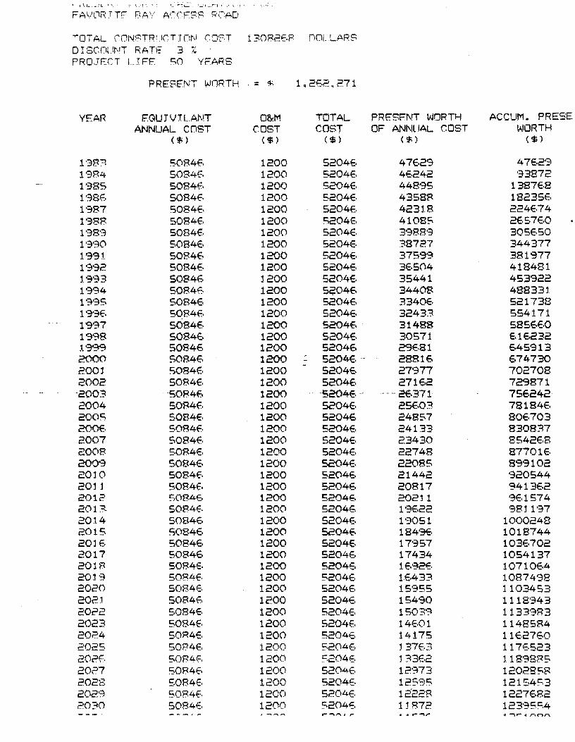
~ I \ L- . _ ~.!.. ... ':'." .. '1', • \," ""':1-... '_'1_!"""'"1 I .1 ~.'1 .
FAVllRTTF F;!~\( ACCFSS h'(iAD
TOTAL eONS TR I, ,Ie T J Dr,1 COST 13082E.8 nOLLARS D I S(:Ol.lf"T RATE 3 f.
PRO.JF::CT I IFF so YFARS
PRESENT WORTH . - ~ . 1. 2E.2, 271
YEAR r::GUJVrL.AI\!T 0&1'1 TOTAL PRE'SFNT WORTH ACCUM. PRESE ANNUAL cnST COST COST OF ANNUAL COST v..IORTH
($ ) ($ ) ($ ) ($ ) ($ )
l'3B? 5084E. 1200 5204E. 47E.29 4762'3 1'384 S084E, 1200 5204E, 46242 '33872 1'385 5084E. 1200 5204E, 44895 1387E.8 l'38E. 5084E. 1200 5204E, 435aR 18235E. 1'387 S084E. 1200 5204E. 4231.8 224674 l'38B 5084E. 1200 S204E. 41085 2E.57E,O 198'3 5084E. 1200 5204E. 3988'3 305650 1'3';30 5084E, 1200 5204E. 38727 344377 1991 50846 1200 5204E. 37599 381977 1'3'32 S084E. 1200 520412. 312,504 418481 1. '3'33 5084E. l200 5204E. 35441 453922 1994 5084E. 1200 S~04E. 34408 488331 l':;i'3S 508412· 1200 520412. 334012. 521738 19'3E. 5084E, 1200 52046 32433 554171 1997 5084E, 1200 S204E, 31488 58S6E.0 1998 S0846 1200 5204E. 30571 E,l6232 19'~ 50846 1200 52046 29681 645913 2000 5084E, 1200 5204E. 28816 E,74730 2001 S084E, 1200 52046 27'377 702708 2002 5084E. 1200 5204E. 27162 729871 -2003 '50846 1200 . --5204E.-· --- 26371 756242-2004 50B4E. 1200 5204E, 2SE,03 7818412. 2005 S084E, 1200 52046 24857 80E.703 200E. 5084f. 1200 5204E, 24133 830837 2007 5084E, 1200 52046 23430 854212.8 2008 SOR4E. 1200 5204E. 22748 87701E. 200'3 5084E. 1200 520412. 22085 899102 2010 5084E. 1200 52046 21442 '320544 201j S084f.. 1200 5204E. 20817 941312.2 2012 ~.084E. 1200 52046 20211 '3E.1574 2013- 5084E. 1200 52046 l'3E.22 9811'37 2014 508412. 1200 52046 1'3051 1000248 2015 5084E. 1200 52046 1849E. 1018744 20j E. 508412. 1200 5204E. 17'357 103E.702 2017 508412. 1200 5204E. 17434 1054137 201.8 508412. 1200 5204E, lE.92E. 10710E.4 2019 5084E. 1200 5204E. lE.433 10874'38 2020 5084E. 1200 5204E. 15955 1103453 202~ 5084E. 1200 5204E. 15490 1118'343 2022 508412. 1200 5204E. 1503'~ 1133983 2023 5084E. 1200 5204E. 14E.Ol 1148584 2024 50R4E. 1200 5204E. 14175 l1E.2760 2025 SOB4E. 1200 5204E. l37e.:3 117E.S23 202f:. 5084(:. 1200 S204E. :!~3E.2 l18'3885 2027 5084E. 1200 52046 12'~73 1202858 2028 S084E. 1200 5204E. 125':7)5 121S4S3 2029 50B4(-. 1200 520412. 12228 122712.82 2030 5084E. 1200 S204E. 11872 123·35!=.4
__ ._1,-,...~""", r '" .. '-~r .. -..- .. r .. nl"'\