Embed Size (px)
Citation preview

Tennessee Valley Authority, Post Office Box 2000, Spring City, Tennessee 37381-2000
MAR 19 200410 CFR 50, App E.
U.S. Nuclear Regulatory CommissionATTN: Document Control DeskWashington, D.C. 20555
Gentlemen:
In the Matter ofTennessee Valley Authority
) Docket No. 50-390
WATTS BAR NUCLEAR PLANT (WBN) - EMERGENCY PLAN IMPLEMENTINGPROCEDURE (EPIP) REVISIONS
In accordance with the requirements of 10 CFR Part 50, Appendix E,Section V, the enclosure provides the following EPIP.
EPIP Rev Title Effective Date
EPIP-13 10 Initial Dose Assessment forRadiological Emergencies
2-20-2004
This EPIP contains a typographical error in Appendix B, Step [31.The last three words of this step are unnecessary and are to bedeleted in the next revision to this EPIP. Step [3] should read"DETERMINE the flow rate for the release path."
There are no regulatory commitments in this letter. If you shouldhave any questions, please contact me at (423) 365-1824.
Sincerely,
P. L. PaceManager, Site Licensing and Industry Affairs
Enclosurecc: See Page 2
U.S. Nuclear Regulatory CommissionPage 2
MAR.1 9 2004
PLP:JESEnclosurecc (Enclosure):
NRC Resident Inspector (w/o Enclosure)Watts Bar Nuclear Plant1260 Nuclear Plant RoadSpring City, Tennessee 37381
U.S. Nuclear Regulatory Commission (2 copies)Region IISam Nunn Atlanta Federal Center61 Forsyth St., SW, Suite 23T85Atlanta, Georgia 30303

TENNESSEE VALLEY AUTHORITY
WATTS BAR NUCLEAR PLANT
EMERGENGY PLAN IMPLEMENTING PROCEDURE
EPIP-13
INITIAL DOSE ASSESSMENTFOR
RADIOLOGICAL EMERGENCIES
Revision 1 0
Unit 0
PREPARED BY: George Crowley/Eddie Woods
SPONSORING ORGANIZATION: Emergency Planning
APPROVED BY: Frank L. Pavlechko
Effective Date: 02/20/2004
LEVEL OF USE: REFERENCE
NON-QUALITY RELATED

WBN INITIAL DOSE ASSESSMENT EPI P-I 3FOR RADIOLOGICAL EMERGENCIES
-, ___REVISION LOGRevision Implementation Pages Description of RevisionNumber Date Affected
8 12/16/2002 All Plan effectiveness determination reviewsindicate the following revisions do not reduce thelevel of effectiveness of the procedure or REP:
Non Intent change. Renumbered instruction forinter-site consistency, formerly EPIP-16. Forhistorical data, source notes, etc., see EPIP-16,Revision 14. Editorial revisions. Deleted sourcenotes, renumbered sections, corrected Appendixreferences.
9 06/02/2003 2, 4, 6,12, Plan effectiveness determination reviews24 indicate the following revisions do not reduce the
level of effectiveness of the procedure or REP:
Non Intent change. Standardized recordretention. Editorial corrections. Revised SQNControl Room access phone number.
K 10 02/20/2004 All Intent change. Added steps in Appendix B tosupport Tritium (TPBAR's) in calculations.Modified TEDE/CDE factors to support infinitecloud methodology to be consistent with CECCEPIP-8. General editorial changes, removeextraneous formatting.
PAGE 2 OF 30 REVISION 10
WBN INITIAL DOSE ASSESSMENT EPIP-1 3FOR RADIOLOGICAL EMERGENCIES
TABLE of CONTENTS
Section Description Page
1.0 PURPOSE 4
2.0 REFERENCES 4
2.1 Interfacing Documents 4
2.2 Other Documents 4
2.3 Definitions/Acronyms 5
3.0 GENERAL INSTRUCTIONS 6
4.0 RECORDS 6
APPENDIX A - "ICS" DOSE ASSESSMENT 7
FIGURE A - SITE MAP 8
APPENDIX B - MANUAL ASSESSMENT OF MONITORED GASEOUS RELEASES 9
APPENDIX C - UNMONITORED RELEASES BASED ON ACCIDENT TYPES 17
APPENDIX D - NOBLE GAS RELEASE RATE EVALUATION 18
APPENDIX E - STEAM LINE RELEASE EVALUATION 20
APPENDIX F - USE OF GRAB SAMPLES FOR GASEOUS EFFLUENT EVALUATION 22
APPENDIX G - TOTAL SITE NOBLE GAS RELEASE RATE 24
APPENDIX H - FLOW ESTIMATES 25
APPENDIX I - CECC LONG TERM DOSE ASSESSMENT 26
APPENDIX J - LOSS OF METEOROLOGICAL DATA 27
PAGE 3 OF 30 REVISION 10

WBN INITIAL DOSE ASSESSMENT EPIP-13FOR RADIOLOGICAL EMERGENCIES
1.0 PURPOSEThis Procedure provides initial guidance to support site activities concerning doseassessment for airborne release situation(s).
2.0 REFERENCES
2.1 Interfacing Documents1. CECC EPIP-8, "Dose Assessment Staff Activities During Nuclear Plant Radiological
Emergencies"2. WBN FSAR3. ICS User's Manual4. EPIP-1, "Emergency Plan Classification Flowchart"
2.2 Other Documents1. TVA NP Radiological Emergency Plan2. NUREG-0654/FEMA REP-1, "Criteria for Preparation and Evaluation of Radiological Emergency
Response Plans and Preparedness in Support of Nuclear Power Plants"K> 3. NUREG 1465, Accident Source Terms for Light-Water Nuclear Power Plants
4. NUREG 1228, Source Terms Estimated During Incident Response to Severe Nuclear Power PlantAccidents
5. Title 10, Code of Federal Regulations, Part 50, Appendix E6. DCN 37910-A7. EPA-4008. Title 10, Code of Federal Regulations, Part 209. Letter, Eberline Instrument Co., to TVA (EEB820919007), 9/19/83 on
(High Range Monitor Efficiencies)10. EPIP-6, Activation and Operation of the Technical Support Center (TSC)11. ODCM12. NE Calculation Package, WBN TSR-008, WBNTSR-009, TI-RPS-162,
WBN NAL 3-003R1, WBN APS 3-08413. SPP-2.6, Computer Software Control14. Watts Bar Nuclear Plant Environmental Data Station Manual.15. Regulatory Guide 1.23, "Onsite Meteorological Programs."16. American Nuclear Society Standard ANSI/ANS-3.11-2000, "Determining Meteorological
Information at Nuclear Facilities."17. Meteorological Data Print Program Users Manual.18. Radiological Emergency Notification Directory (REND).19. Watts Bar Nuclear Plant Nowcast Manual, October 1991.20. ANSI N18.7-1976
PAGE 4 OF 30 REVISION 10
WBN INITIAL DOSE ASSESSMENT EPIP-13FOR RADIOLOGICAL EMERGENCIES
2.3 DefinitionslAcronyms
AIRBORNE RELEASE: Release of airborne radioactive material from the site into theenvironment.
CECC: Central Emergency Control Center.
EXCLUSION AREA BOUNDARY: The demarcation of the area (0.62 mile) surrounding theWBN units in which postulated FSAR accidents will not result in population doses exceedingthe criteria of 1 OCFR Part 100. (See Figure A of this procedure).
ICS: Integrated Computer System.
PAG: Protective Action Guide. Specific levels of radiation dose control established by theEnvironment Protection Agency, (i.e., I REM TEDE, 5 REM Thyroid CDE).
RE/RM ICS references radiological elements (RE). The control room also has radiologicalmonitors (RM) connected to these elements. For the purposes of this procedure theseacronyms can be used interchangeably.
SITE BOUNDARY: The Site Boundary used here is consistent with the definition in the OffsiteDose Calculation Manual. (See Figure A of this procedure). The appropriate boundarybetween 'onsite" and "offsite".
SITE PERIMETER (SP): An area encompassing owner controlled areas in the immediatesite environment. Measurements are taken at the 16 identified radiological monitoringpoints along the Site Perimeter. (See Figure A of this procedure).
STABILITY CLASS: An index (A-G) to represent the degree of mixing in the atmosphere.
TEDE: Total Effective Dose Equivalent. The TEDE dose is equivalent to the sum of theplume EDE, the inhalation EDE, and the ground EDE.
THYROID CDE: Thyroid Committed Dose Equivalent.
X/Q: The release dilution ratio between concentrations (X) at reception point (e.g., SP) tothe source strength (Q) at a given release point. This dilution ratio is incorporated into thetables for Appendix B.
PAGE 5 OF 30 REVISION 10

WBN INITIAL DOSE ASSESSMENT EPI P-1 3FOR RADIOLOGICAL EMERGENCIES
3.0 GENERAL INSTRUCTIONS
3.1 The onshift Radiological Control Group (RADCON) is responsible for completing thisprocedure should the CECC/TSC not be activated. This procedure will be performed asdirected by the SEDISM when a dose assessment is necessary.
3.2 For initial dose assessment activities, COMPLETE the instructions found in Appendix A,"ICS, Dose Assessment."
3.3 Should ICS dose assessment be unavailable use the backup calculation method inAppendix B for the Site Boundary and five mile zones.
4.0 RECORDS
4.1 Records of Classified Emergencies
The materials generated in support of key actions during an actual emergencyare considered Lifetime retention Non-QA records. Materials shall beforwarded to the EP Manager who shall submit any records deemed necessaryto demonstrate performance to the Corporate EP Manager for storage.
4.2 Drill and Exercise Records
The materials deemed necessary to demonstrate performance of key actionsduring drills are considered Non-QA records. These records shall beforwarded to the EP Manager who shall retain records deemed necessary todemonstrate six-year plan performance for six years. The EP Manager shallretain other records in this category for three years.
PAGE 6 OF 30 REVISION 10
WBN INITIAL DOSE ASSESSMENT EPIP 13FOR RADIOLOGICAL EMERGENCIES E
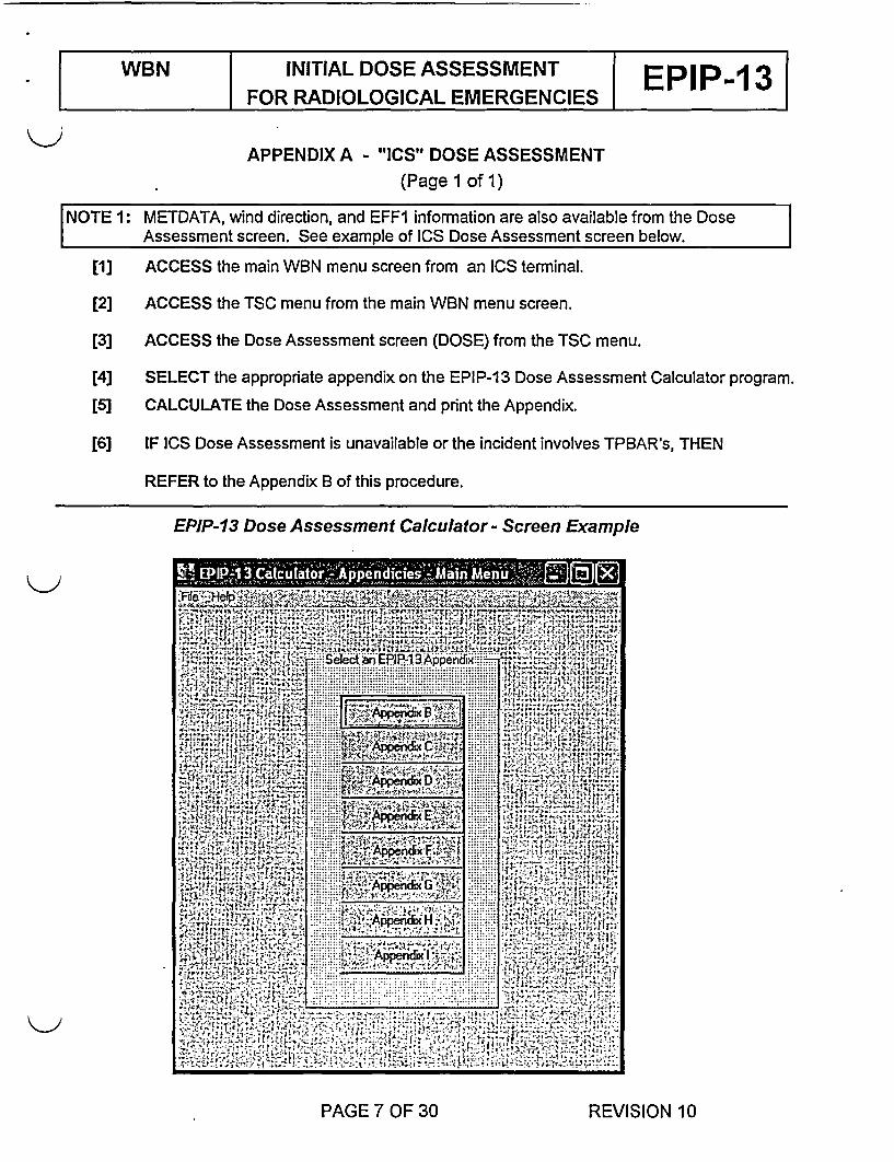
APPENDIX A - "ICS" DOSE ASSESSMENT(Page 1 of 1)
NOTE 1: METDATA, wind direction, and EFF1 information are also available from the Dose| Assessment screen. See example of ICS Dose Assessment screen below.
[1] ACCESS the main WBN menu screen from an ICS terminal.
[2] ACCESS the TSC menu from the main WBN menu screen.
[3] ACCESS the Dose Assessment screen (DOSE) from the TSC menu.
[4] SELECT the appropriate appendix on the EPIP-13 Dose Assessment Calculator program.
[5] CALCULATE the Dose Assessment and print the Appendix.
[6] IF ICS Dose Assessment is unavailable or the incident involves TPBAR's, THEN
REFER to the Appendix B of this procedure.
EPIP-13 Dose Assessment Calculator - Screen Example
PAGE 7 OF 30 REVISION 10

WBN INITIAL DOSE ASSESSMENT EPIFOR RADIOLOGICAL EMERGENCIES P-13
FIGURE A - SITE MAP(Page 1 of 1)
PAGE 8 OF 30 REVISION 10

WBN INITIAL DOSE ASSESSMENTFOR RADIOLOGICAL EMERGENCIES E
APPENDIX B - MANUAL ASSESSMENT OF MONITORED GASEOUS RELEASES(Page 1 of 8)
[1] IF the incident does not involve TPBAR, THEN
GO TO step [11].
[2] REQUEST Chemistry to obtain a sample of the appropriate gaseous release fortritium.
NOTE Appendix F may be referred to during periods when ICS is unavailable to obtain release flowI rate.
[3] DETERMINE the flow rate for the release path that tritium being
[4] DETERMINE the tritium release rate by completing the following table.
A | B C D=AxBxCTritium Release Conversion factor to Tritium Release
Concentration Flowrate convert scfm to cc/s. Rate[ICi/cc scfm __Ci/s
472 cc/s/scfm
FNOTE Appendix J may be referred to during periods when the Meteorological data is unavailable. I
[5] OBTAIN Stability Class from the MET DATA screen on ICS or from SQN controlroom (843-7860) and CIRCLE the Stability Class in both tables below.
[6] IF the Stability Class cannot be obtained, THEN
DETERMINE the stability class by subtracting the 10 meter from the 46 meter temperaturesand CIRCLE the stability class in both tables below.
A• -1.24 B -1.1 I to -1.23 C -.98 to -1.1 0 D -.33 to -.97 E .97 to -.32 F 2.59 to .98 G 2 2.6
[7] OBTAIN the wind speed in mph from the 46 meter heightand CIRCLE the appropriate range for the wind speed inboth tables below.
PAGE 9 OF 30 REVISION 10

WBN INITIAL DOSE ASSESSMENTFOR RADIOLOGICAL EMERGENCIES E 3
K) APPENDIX B - MANUAL ASSESSMENT OF MONITORED GASEOUS RELEASES(Page 2 of 8)
[8] CIRCLE the appropriate Tritium TEDE factors for each distance in the tables below basedon the wind speed and stability class obtained in the above steps.
0.62 Mile Tritium TEDE Factors
Stability <2.2 >2.2 >4.4 >6.6 >8.8 >11 >13.2 >15.4 >17.6 >19.8Class mph <=4.4 <=6.6 <=8.8 <=11 <=13.2 <=15.4 <=17.6 <=19.8 mph
mph mmph p mph mph mph mph mphA 2.5E-10 1.3E-10 8.3E-11 6.3E-11 5.0E-1 1 4.2E-1 1 3.6E-1 1 3.1 E-11 2.8E-11 2.5E-1 1B 1.2E-09 6.0E-10 4.0E-10 3.0E-10 2.4E-10 2.0E-10 1.7E-10 1.5E-10 1.3E-10 1.2E-10C 3.5E-09 1.8E-09 1.2E-09 8.8E-10 7.0E-10 5.8E-10 5.0E-10 4.42-10 3.9E-10 3.5E-10D 1.0E-08 5.0E-09 3.3E-09 2.5E-09 2.OE-09 1.7E-09 1.4E-09 1.3E-09 1.1E-09 1.OE-09E 1.7E-08 8.5E-09 5.7E-09 4.3E-09 3.4E-09 2.8E-09 2.4E-09 2.1 E-09 1.9E-09 1.7E-09F 3.3E-08 1.7E-08 1.1E-08 8.3E-09 6.6E-09 5.5E-09 4.7E-09 4.1 E-09 3.7E-09 3.3E-09G 7.0E-08 3.5E-08 2.3E-08 1.82-08 1.4E-08 1.2E-08 1.OE-08 8.8E-09 7.8E-09 7.0E-09
5 Mile Tritium TEDE Factors
Stability <2.2 >2.2 >4.4 >6.6 >8.8 >11 >13.2 >15.4 >17.6 >19.8Class mph <=4.4 <=6.6 <=8.8 <=11 <=13.2 <=15.4 <=17.6 <=19.8 mph
mph mph mph mph mph mph mph mphA 4.0E-11 2.0E-11 1.3E-11 1.0E-11 8.OE-12 6.7E-12 5.7E-12 5.0E-12 4.4E-12 4.OE-12B 5.0E-11 2.5E-11 1.7E-11 1.3E-11 1.0E-11 8.3E-12 7.1E-12 6.3E-12 5.6E-12 5.0E-12C 1.1E-10 5.5E-11 3.7E-11 2.8E-11 2.2E-11 1.8E-11 1.6E-11 1.4E-11 1.2E-11 1.1E-11D 4.4E-10 2.2E-10 1.5E-10 1.1E-10 8.8E-11 7.3E-11 6.3E-11 5.5E-11 4.9E-11 4.4E-11E 9.5E-10 4.8E-10 3.2E-10 2.4E-10 1.9E-10 1.6E-10 1.4E-10 1.2E-10 1.1E-10 9.5E-11F 2.4E-09 1.2E-09 8.02-10 6.0E-10 4.8E-10 4.0E-10 3.4E-10 3.0E-10 2.7E-10 2.4E-10G 5.5E-09 2.8E-09 1.8E-09 1.4E-09 1.1E-09 9.2E-10 7.9E-10 6.9E-10 6.1E-10 5.52-10
I NOTE A duration of 4 hours should be used when the release duration is unknown. Il
[9] OBTAIN and RECORD the estimated duration of the release in hours from the SM.
[10] CALCULATE the Tritium TEDE dose at .62 and 5 by multiplying the Tritium release rate xTEDE factor x Release duration = Tritium TEDE Dose.
Tritium TEDE DOSES
Distance Tritium Tritium Release Tritium TEDERelease Rate TEDE Factor Duration Dose
R±Ci/s - | hour(s) (REM)0.62
[ 5.0
Prepared by:.
Date/Time:
PAGE 10 OF 30 REVISION 10

WBN INITIAL DOSE ASSESSMENT EPIP-13FOR RADIOLOGICAL EMERGENCIES
kd APPENDIX B - MANUAL ASSESSMENT OF MONITORED GASEOUS RELEASES(Page 3 of 8)
I NOTE Appendix J may be referred to during periods when the Meteorological data is unavailable.
[11] OBTAIN Stability Class from the MET DATA screen on ICS or from the SQN control room(843-7860) and CIRCLE the Stability Class in both tables below.
[12] IF the Stability Class cannot be obtained, THEN
DETERMINE the stability class by subtracting the 10 meter from the 46 meter temperatures andCIRCLE the stability class in both tables below.
As-1.24 B-1.l1 to-1.23 C-.98to-1.10 D-.33to-.97 E .97to-.32 F2.59to.98 G22.6
[13] OBTAIN the wind speed in mph from the 46 meter height and CIRCLE the appropriaterange for the wind speed in both tables below.
[14] CIRCLE the appropriate Noble Gas TEDE factors for each distance in the tables belowbased on the wind speed and stability class obtained in the above steps.
0.62 Miles Noble Gas TEDE Factors
Stability <2.2 >2.2 >4.4 >6.6 >8.8 >11 >13.2 >15.4 >17.6 >19.8Class mph <=4.4 <=6.6 <=8.8 <=11 <=13.2 <=15.4 <=17.6 <=19.8 mph
mph mph mph mph mph mph mph mph . -
A 6.0E-10 3.0E-10 2.0E-10 1.5E-10 1.2E-10 1.OE-10 8.6E-11 7.5E-11 6.7E-11 6.OE-11B 2.1 E-09 1.12-09 7.0E-10 5.3E-10 4.2E-10 3.5E-10 3.0E-10 2.6E-10 2.3E-10 2.1 E-10C 4.6E-09 2.3E-09 1.5E-09 1.2E-09 9.2E-10 7.7E-10 6.6E-1 0 5.8E-10 5.1E-10 4.6E-10D 9.5E-09 4.8E-09 3.2E-09 2.4E-09 1.9E-09 1.6E-09 1.4E-09 1.2E-09 1.1 E-09 9.5E-10E 1.4E-08 7.0E-09 4.7E-09 3.5E-09 2.8E-09 2.3E-09 2.0E-09 1.8E-09 1.6E-09 1.4E-09F 2.12-08 1.1E-08 7.0E-09 5.3E-09 4.2E-09 3.5E-09 3.0E-09 2.6E-09 2.3E-09 2.1E-09G 3.5E-08 1.8E-08 1.2E-08 8.8E-09 7.0E-09 5.8E-09 5.0E-09 4.4E-09 3.92-09 3.5E-09
5 Miles Noble Gas TEDE Factors
Stability <2.2 >2.2 >4.4 >6.6 >8.8 >11 >13.2 >15.4 >17.6 >19.8Class mph <=4.4 <=6.6 <=8.8 <=11 <=13.2 <=15.4 <=17.6 <=19.8 mph
mph mph mph mph mph mph mph mph
A 9.5E-11 4.8E-11 3.2E-11 2.4E-11 1.9E-11 1.6E-11 1.4E-11 1.2E-11 1.1E-11 9.5E-12B 1.5E-10 7.5E-11 5.0E-11 3.8E-11 3.0E-11 2.5E-11 2.1 E-11 1.9E-11 1.7E-11 1.5E-11C 2.8E-10 1.4E-10 9.3E-11 7.0E-11 5.6E-11 4.7E-11 4.0E-11 3.5E-11 3.1E-11 2.8E-11D 9.5E-10 4.8E-10 3.2E-10 2.4E-10 1.9E-10 1.6E-10 1.4E-10 1.2E-10 1.1E-10 9.5E-11E 1.8E-09 9.0E-10 6.0E-10 4.5E-10 3.6E-10 3.0E-10 2.6E-10 2.3E-10 2.0E-10 1.8E-10F 3.5E-09 1.82-09 1.2E-09 8.8E-10 7.0E-10 5.8E-10 5.0E-10 4.42-10 3.9E-10 3.5E-10G 6.5E-09 3.3E-09 2.2E-09 1.62-09 1.3E-09 1.12-09 9.32-10 8.1E-10 7.2E-10 6.5E-10
PAGE 11 OF 30 REVISION 10

WBN INITIAL DOSE ASSESSMENT| FOR RADIOLOGICAL EMERGENCIES E 3
<_J APPENDIX B - MANUAL ASSESSMENT OF MONITORED GASEOUS RELEASES(Page 4 of 8)
LNOTE RCS fuel damage should be used when the fuel damage is unknown. I
[15] DETERMINE and CIRCLE the TEDE ratio based on the release path and type of fueldamage for both 0.62 and 5 mile distances using the table below.
I NOTE The SM may be able to assist in determining the release paths and type of fuel damage. I
Release Paths
Containment leak filteredContainment leak unfiltered or SGTR below the waterTurbine, Reactor, or Auxiliary BuildingSGTR above the water
Tvye of Fuel Damage
Normal reactor coolant systemFuel clad gapCore damage (fuel over temp)Fuel melt
0.62 Mile TEDE Ratios
RCS Gap Core FuelDamage Melt
CNTMT (filtered) 3.7 1.0 0.9 1.0CNTMT (unfiltered) or SGTR (below) 7.4 9.0 5.3 11
Turbine, Reactor, or Auxiliary Building 17 32 16 37SGTR (above) 95 221 111 263
5 Miles TEDE Ratios
RCS Gap Core FuelDamage Melt
CNTMT (filtered) 1.8 1.0 1.0 1.0CNTMT (unfiltered) or SGTR (below) 3.5 4.9 2.9 5.8
Turbine, Reactor, or Auxiliary Building 7.4 15 7.9 17SGTR (above) 43 100 51 116
[16] IF ICS is unavailable, THEN
NOTIFY the SM that Appendix D must be performed by RADCON/Chemistry personnel in TSC.
[17] IF Radiation Monitor data is unavailable or the release is not monitored, THENuse Appendix C to determine the noble gas release rate.
PAGE 12 OF 30 REVISION 10

WBN INITIAL DOSE ASSESSMENTFOR RADIOLOGICAL EMERGENCIES E 3
K.) APPENDIX B - MANUAL ASSESSMENT OF MONITORED GASEOUS RELEASES(Page 5 of 8)
[18] COMPLETE the following NG TEDE Dose table for both 0.62 and 5 mile as follows:
[a] OBTAIN and RECORD the Noble Gas release rate from ICS EFF1 or appropriateappendix.
[bJ RECORD the NG TEDE Factors determined in step [14].
[c] RECORD the TEDE Ratios determined in step [15].
NOTE A duration of 4 hours should be used when the release duration is unknown.
[d] OBTAIN and RECORD the estimated duration of the release in hours from the SM orif the release is unmonitored use release duration associated with accident type fromAppendix C.
[e] CALCULATE the TEDE dose at .62 and 5 by multiplying the NG release rate xTEDE Factorx TEDE Ratio x Release Duration = NG TEDE Dose.
Noble Gas TEDE DOSESDistance Noble Gas Noble Gas TEDE Ratio Release Noble Gas
Release Rate TEDE Factor Duration TEDE Dosex _ Ci/s hour(s) (REM)
0.62
5.0
[19] COMPLETE the following Total TEDE Dose table for both 0.62 and 5 mile as follows:
[a] OBTAIN and RECORD the tritium TEDE Dose (REM).
[b] OBTAIN and RECORD the noble gas TEDE Dose (REM).
[qJ ADD the Tritium and Noble Gaseous TEDE Doses.
TOTAL TEDE DOSES
Distance Tritium TEDE Noble Gas TotalDose TEDE Dose TEDE(REM) (REM) (REM)
0.62
5.0
Prepared by:
Date/Time:-
PAGE 13 OF 30 REVISION 10

WBN INITIAL DOSE ASSESSMENTFOR RADIOLOGICAL EMERGENCIES E
K\> APPENDIX B - MANUAL ASSESSMENT OF MONITORED GASEOUS RELEASES(Page 6 of 8)
I NOTE Appendix J may be referred to during periods when the Meteorological data is unavailable. I
120] OBTAIN Stability Class from the MET DATA screen on ICS or from the SON control room(843-7860) and CIRCLE the Stability Class in both tables below.
[21] IF the Stability Class cannot be obtained, THEN
DETERMINE the stability class by subtracting the 10 meter from the 46 meter temperatures andCIRCLE the stability class in both tables below.
A•-i.24 B -1.1 1to -1.23 C:-.98 to -1.1 0 D. .33to-.97 E .971to -.32 F 2.59 to .98 G 22.6
122] OBTAIN the wind speed in mph from the 46 meter height and CIRCLE the appropriaterange for the wind speed in both tables below.
[23] CIRCLE the appropriate CDE Factors for each distance in the tables below based on thewind speed and stability class obtained in the above steps.
0.62 Miles CDE Factors
Stability <2.2 >2.2 >4.4 >6.6 >8.8 >11 >13.2 >15.4 >17.6 >19.8Class mph <=4.4 <=6.6 <=8.8 <=11 <=13.2 <=15.4 <=17.6 <=19.8 mph
mph mph mph mph mph mph mph mph
A 1.2E-05 6.0E-06 4.0E-06 3.0E-06 2.4E-06 2.0E-06 1.7E-06 1.5E-06 1.3E-06 1.2E-06
B 5.8E-05 2.9E-05 1.9E-05 1.5E-05 1.2E-05 9.7E-06 8.3E-06 7.3E-06 6.4E-06 5.8E-06
C 1.7E-04 8.5E-05 5.7E-05 4.3E-05 3.4E-05 2.8E-05 2.4E-05 2.1 E-05 1.9E-05 1.7E-05
D 4.8E-04 2.4E-04 1.6E-04 1.2E-04 9.6E-05 8.0E-05 6.9E-05 6.0E-05 5.3E-05 4.8E-05
E 8.3E-04 4.2E-04 2.8E-04 2.1E-04 1.7E-04 1.4E-04 1.2E-04 1.OE-04 9.2E-05 8.3E-05
F 1.6E-03 8.0E-04 5.3E-04 4.0E-04 3.2E-04 2.7E-04 2.3E-04 2.OE-04 1.8E-04 1.6E-04
G 3.5E-03 1.8E-03 1.2E-03 8.8E-04 7.OE-04 5.8E-04 5.0E-04 4.4E-04 3.9E-04 3.5E-04
5 Miles CDE Factors
Stability <2.2 >2.2 >4.4 >6.6 >8.8 >11 >13.2 >15.4 >17.6 >19.8Class mph <=4.4 <=6.6 <=8.8 <=11 <=13.2 <=15.4 <=17.6 <=19.8 mph
mph mph mph mph mph mph mph mph ___
A 2.OE-06 1.OE-06 6.7E-07 5.0E-07 4.OE-07 3.3E-07 2.9E-07 2.5E-07 2.2E-07 2.OE-07
B 2.5E-06 1.3E-06 8.3E-07 6.3E-07 5.0E-07 4.2E-07 3.6E-07 3.1 E-07 2.8E-07 2.5E-07
C 5.OE-06 2.5E-06 1.7E-06 1.3E-06 1.0E-06 8.3E-07 7.1 E-07 6.32-07 5.6E-07 5.0E-07
D 2.2E-05 1.1E-05 7.3E-06 5.5E-06 4.4E-06 3.7E-06 3.1 E-06 2.8E-06 2.4E-06 2.2E-06
E 4.7E-05 2.4E-05 1.6E-05 1.2E-05 9.4E-06 7.8E-06 6.7E-06 5.9E-06 5.2E-06 4.7E-06
F 1.2E-04 6.0E-05 4.0E-05 I3.0E-05 I2.4E-05 I2.0E-05 1.7E-05 1.5E-05 I1.3E-05 1.2E-05
G 2.7E-04 1.4E-04 I 9.0E-05 6.8E-05 5.4E-05 I 4.5E-05 I 3.9E-05 3A4-05 3.OE-05 2.7E-05
PAGE 14 OF 30 REVISION 10

WBN INITIAL DOSE ASSESSMENT EPIP 3FOR RADIOLOGICAL EMERGENCIES E 3
Kj APPENDIX B - MANUAL ASSESSMENT OF MONITORED GASEOUS RELEASES(Page 7 of 8)
NOTE I RCS fuel damage should be used when the fuel damage is unknown.
NOTE 2 The SM may be able to assist in determining the release paths and type of fuel damage.
[24] DETERMINE and CIRCLE the Iodine to Noble Gas ratio based on the release path and typeof fuel damage using the table below.
Release Paths
Containment leak filteredContainment leak -ufiltered or SGTR below the waterTurbine, Reactor, or Auxiliary BuildingSGTR above the water
Tvpe of Fuel Damage
Normal reactor coolant systemFuel clad gapCore damage (fuel over temp)Fuel melt
Iodine to NG Ratios
RCS Gap Core FuelDamage Melt
CNTMT (filtered) 1.7E-06 3.OE-05 1.2E-05 2.2E-05CNTMT (unfiltered) or SGTR (below) 1.7E-04 3.OE-03 1.2E-03 2.2E-03
Turbine, Reactor, or Auxiliary Building 5.8E-04 1.0E-02 4.1E-03 7.7E-03SGTR (above) 4.2E-03 8.OE-02 3.0E-02 5.5E-02
[25] IF ICS is unavailable, THEN
NOTIFY the SM that Appendix D must be performed by RADCON/Chemistry personnel in TSC.
[26] IF Radiation monitor data is unavailable or the release is not monitored, THENUse Appendix C to determine the noble gas release rate.
PAGE 15 OF 30 REVISION 10
WBN INITIAL DOSE ASSESSMENT EPIP-1 3FOR RADIOLOGICAL EMERGENCIES
K-j APPENDIX B - MANUAL ASSESSMENT OF MONITORED GASEOUS RELEASES(Page 8 of 8)
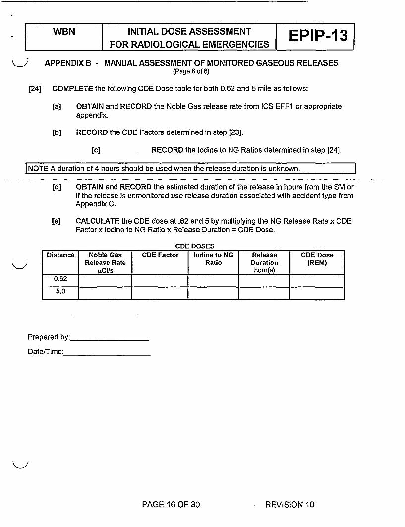
[24] COMPLETE the following CDE Dose table for both 0.62 and 5 mile as follows:
[a] OBTAIN and RECORD the Noble Gas release rate from [CS EFF1 or appropriateappendix.
[b] RECORD the CDE Factors determined in step [23].
[c] RECORD the Iodine to NG Ratios determined in step [24].
I NOTE A duration of 4 hours should be used when the release duration is unknown. I
[d] OBTAIN and RECORD the estimated duration of the release in hours from the SM orif the release is unmonitored use release duration associated with accident type fromAppendix C.
[e] CALCULATE the CDE dose at .62 and 5 by multiplying the NG Release Rate x CDEFactor x Iodine to NG Ratio x Release Duration = CDE Dose.
CDE DOSESDistance Noble Gas CDE Factor Iodine to NG Release CDE Dose
Release Rate Ratio Duration (REM)_Ci/s hour(s)
0.62
5.0 1
Prepared by:
Date/Time:_
PAGE 16 OF 30 REVISION 10

WBN INITIAL DOSE ASSESSMENT EPIP 13FOR RADIOLOGICAL EMERGENCIES E-
APPENDIX C - UNMONITORED RELEASES BASED ON ACCIDENT TYPES(Page 1 of 1)
Summary of Accident Types Duration of the Noble GasRelease Release
(Consult with SM to determine the Accident type to use.) Rates(Hours) PCi/s
LOCA - 100% Fuel Melt(>1200F) RCSContainment Tech Spec allowed leakage (0.25%/24 hours) 24 1.1 6E+07Containment Failure(100%/4 hours) 4 2.79E+1O0
LOCA - 100% Gap Activity RCS l l _|Containment Tech Spec allowed leakage(0.25%/24 hours) 24 6.34E+03Containment Failure(1 00%14 hours) 4 1.52E+07
LOCA - Normal RCSContainment Tech Spec allowed leakage(0.25%/24 hours) 24 3.40E+01Containment Failure(100%14 hours) 4 8.15E+04
SG Tube Rupture0-2 hours after the beginning of the release 2 3.87E+062-8 hours after the beginning of the release 6 2.14E+00
Fuel Handling - One Bundle Damaged l lAccident inside Containment with Purge fans on 2 1.89E+05Accident outside Containment with ABGTS on 0.25 1.51 E+06
| Waste Gas Decay Tank Rupture l | _ _|Reg. guide 1.24 analysis I 2.09E+07
PAGE 17 OF 30 REVISION 10

| WBN INITIAL DOSE ASSESSMENT EPIP 3| | FOR RADIOLOGICAL EMERGENCIES E 3
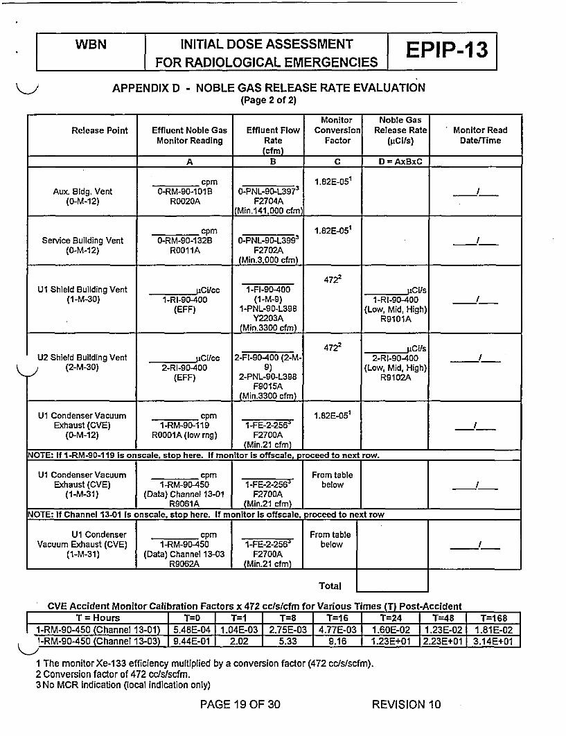
APPENDIX D - NOBLE GAS RELEASE RATE EVALUATION(Page 1 of 2)
NOTE 1: If ICS is not functional and time is not available due to the ongoing emergency event,wait for the TSC to activate prior to proceeding in this appendix. _
NOTE 2: In columns A and B of this Appendix, the radiation monitor and panel number, alongwith the ICS or Eberline computer oints necessary to obtain the data, are listed.Monitors indicating "offscaleH (>10 cpm for monitors on panels 1 or 2-M-30) should beindicated as such.
[1] OBTAIN and RECORD the noble gas monitor readings on page 2 of thisAppendix.
NOTE: Flow rates that are less than the minimum value indicated should be reported as theminimum value.
[2] RECORD the effluent flow rate(s) on page 2 of this Appendix.
[3] IF flow instrumentation is inoperable, THEN
OBTAIN flow estimates using Appendix H.
)[4] CALCULATE the noble gas release rates on page 2 of this Appendix.
[5] SUM the noble gas release rates, AND
RECORD the gaseous noble gas release rate total on page 2 of this Appendix.
[6] TRANSFER the gaseous noble gas release rate to Appendix G.
PAGE 18 OF 30 REVISION 10
WBN INITIAL DOSE ASSESSMENT EPIP 13FOR RADIOLOGICAL EMERGENCIES
APPENDIX D - NOBLE GAS RELEASE RATE EVALUATION(Page 2 of 2)
Monitor Noble GasRelease Point Effluent Noble Gas Effluent Flow Conversion Release Rate Monitor Read
Monitor Reading Rate Factor (giCi/s) DatelTime(cfm)
A B C D =AxBxC __
cpm 1.82E-05'Aux Bldg. Vent O-RM-90-101B O-PNL-90-L3973
3
(O-M-12) R0020A F2704A(Min.141,000 cfm)
cpm 1.82E-05'Service Building Vent 0-RM-90-132B O-PNL-90-L3993 .
(O-M-12) R0011A F2702A(Min.3,000 cfm)
4722U1 Shield Building Vent UCi/cc 1-FI-90-400 Us
(1-M-30) 1-RI-90-400 (1-M-9) 1-RI-90-400 /(EFF) 1-PNL-90-L398 (Low, Mid, High)
Y2203A R9101A(Min.3300 cfm)
4722 uCi/sU2 Shield Building Vent jiCi/cc 2-FI-90-400 (2-M- 2-RI-90-400 /
(2-M-30) 2-RI-90-400 9) (Low, Mid, High)(EFF) 2-PNL-90-L398 R9102A
F9015A(Min.3300 cfm)
U1 Condenser Vacuum cpm 1.82E-051
Exhaust (CVE) 1-RM-9D-119 1-FE-2-256 I_(0-M-12) R0001A (low mg) F2700A
(Min.21 cfm) _-NOTE: If 1-RM-90-119 Is onscale, stop here. If monitor Is offscale, p oceed to next row.
U1 Condenser Vacuum cpm From tableExhaust (CVE) IE1-RM-902450 F-2-56 below I
(1-M-31) (Data) Channel 13-01 F2700AR9061A (Min.21 cfm)
NOTE: If Channel 13.01 Is onscale, stop here. If monitor Is offscale, proceed to next row
U1 Condenser cpm From tableVacuum Exhaust (CVE) 1-RM-90-450 -FE2-2-563 below I
(1-M-31) (Data) Channel 13-03 F2700AR9062A (Min.21 cfm)
Total
CVE Accident Monitor Calibration Factors x 472 cclslcfm for Various Times (T) Post-AccidentT = Hours I T0 T=1 I T=8 I T16 T=24 I T=48 T=168
1-RM-90-450 (Channel 13-01) 5.48E-04 1.04E-03 2.75E-03 4.77E-03 1.60E-02 I1.23E-02 1.81 E-02I-RM-90-450 (Channel 13-03) I 9.44E-01 I 2.02 I 5.33 I 9.16 I 1.23E+01 12.23E+01 I 3.14E+01
I The monitor Xe-1 33 efficiency multiplied by a conversion factor (472 cc/s/scfm).2 Conversion factor of 472 cc/s/scfm.3 No MCR indication (local indication only)
PAGE 19 OF 30 REVISION 10

WBN INITIAL DOSE ASSESSMENTFOR RADIOLOGICAL EMERGENCIES
APPENDIX E - STEAM LINE RELEASE EVALUATION(Page 1 of 2)
[1] OBTAIN and RECORD the steam line radiation monitor readings on page 2 of thisAppendix.
[2] DETERMINE and CIRCLE the appropriate calibration factor listed on page 2 of thisAppendix AND
RECORD the value on page 2 of this Appendix.
[NOTE Engineering may be consulted to determine the best estimate of steam flow duringO periods when ICS steam flow is unavailable.
[3] OBTAIN and RECORD the steam mass flow rates on page 2 of this Appendix.
[4] CALCULATE the steam line release rates on page 2 of this Appendix.
[5] SUM the release rates for the steam lines, and
RECORD the total steam line noble gas release rate on page 2 of this Appendix.
[6] TRANSFER the steam line noble gas release rate to Appendix G.
PAGE 20 OF 30 REVISION 10

WBN INITIAL DOSE ASSESSMENTFOR RADIOLOGICAL EMERGENCIES EI-
APPENDIX E - STEAM LINE RELEASE(Page 2 of 2)
EVALUATION
Steam Line Radiation Calibration Factor Steam Mass Conversion ReleaseMonitor Reading (from table below) Flow Rate' Factor2 Rate
(mR/hr) (gCi/cc per mRlhr) (Ibm/hr) _ ( Cils)A B C D AxBxCxD
Steam Generator RM-90-4218 (1 -M-30) 4.451 RR-90-268 Pt.01 (1-M-31)
R9055A
Steam Generator RM-90-422B (1-M-30) 4.452 RR-90-268 Pt.02 (1-M-31)
R9056A
Steam Generator3 RM-90-423B (1-M-30) 4.45
RR-90-268 Pt.03 (1-M-31)
R9057A
Steam Generator4 RM-90-424B (1-M-30)
RR-90-268 Pt.04 (1-M-31)R9058A
4.45
Auxiliary . .Feedwater Pump 4.45
Turbine RM-90-421B (1-M-30) orRM-90-424B (1-M-30)
Total1 This data is an internal ICS calculation.2 4.45 = [cc(steam)I0.0283 g] x g/2.205E-3 Ibm x hr13600 sec
Main Steam Line Radiation Monitor Calibration Factors (CF)
Time After Shutdown Normal Spectrum Monitor DBA Spectrum Monitor Reading(hrs) Reading < 1000 mR/hr > 1000 mR/hr or Suspected Fuel
(,uCi/cc per mR/hr) Damage (g±Ci/cc per mRlhr)0 3.OOE-3 9.88E-51 5.13E-3 7.79E-42 6.11 E-3 5.41 E-34 7.76E-3 6.86E-38 1.09E-2 9.63E-3
PAGE 21 OF 30 REVISION 10

WBN INITIAL DOSE ASSESSMENTFOR RADIOLOGICAL EMERGENCIES EPIP-1 3
APPENDIX F - USE OF GRAB SAMPLES FOR GASEOUS EFFLUENT EVALUATION(Page 1 of 2)
[1] IF sampling analysis is required to determine the site release rates, THEN
REQUEST noble gas samples be obtained from applicable release pointsthat have flow.
[2] RECORD sample date(s) and time(s) for applicable release point(s) on page 2 ofthis Appendix.
NOTE 1: Flow rates that are less than the minimum value indicated should be reported as the |minimum value.
NOTE 2: Operations may be required to obtain flowrate for 1-FE-2-256, Condenser VacuumExhaust.
[3] RECORD the effluent flow rate(s) on page 2 of this Appendix.
[4] IF flow instrumentation is inoperable, THEN
OBTAIN flow estimates using Appendix H.
[5] RECORD the total noble gas concentration for applicable release point(s) onpage 2 of this Appendix.
[6] CALCULATE the total noble gas release rate as indicated on page 2 of this Appendix
[7] SUM the noble gas release rates, AND
RECORD the total gaseous noble gas release rate on page 2 of this Appendix.
[8] TRANSFER the gaseous noble gas release rate to Appendix G.
PAGE 22 OF 30 REVISION 10
WBN INITIAL DOSE ASSESSMENT EPIP-1 3|FOR RADIOLOGICAL EMERGENCIES
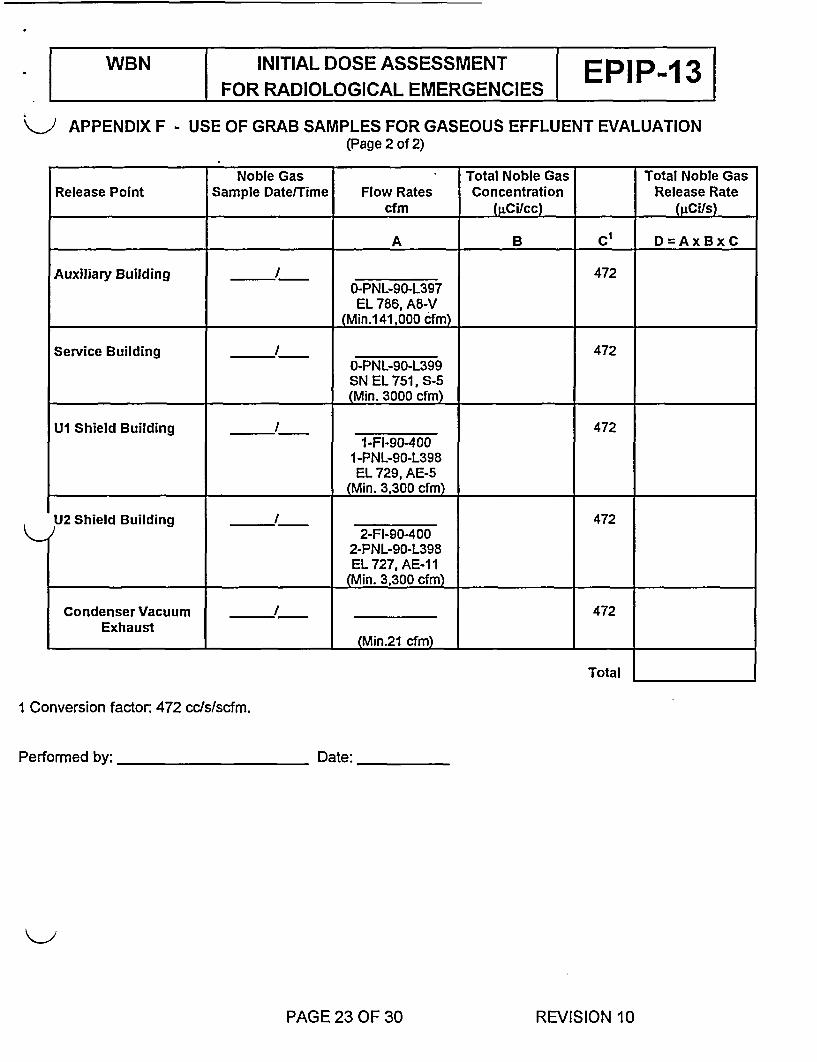
K J APPENDIX F - USE OF GRAB SAMPLES FOR GASEOUS EFFLUENT EVALUATION(Page 2 of 2)
Noble Gas Total Noble Gas Total Noble GasRelease Point Sample Date/Time Flow Rates Concentration Release Rate
cfm (RCi/cc) (4cifs)
A B C' D=AxBxC
Auxiliary Building / 4720-PNL-90-L397EL 786, A8-V
(Min.141,000 cfm)
Service Building / 4720-PNL-90-L399SN EL 751, S-5(Min. 3000 cfm)
U1 Shield Building / 4721-FI-90400
I-PNL-90-L398EL 729, AE-5
(Min. 3,300 cfm)
U2 Shield Building I 4722-FI-90-400
2-PNL-90-L398EL 727, AE-1 I
(Min. 3,300 cfm)
Condenser Vacuum / . 472Exhaust (Min.21 cfm)
Total
I Conversion factor: 472 cc/s/scfm.
Performed by: Date:
PAGE 23 OF 30 REVISION 10

WBN INITIAL DOSE ASSESSMENT EPIP 3FOR RADIOLOGICAL EMERGENCIES E 3
[1]
[2]
APPENDIX G - TOTAL SITE NOBLE GAS RELEASE RATE(Page 1 of 1)
SUM the values listed below to obtain the total site noble gas release rate.
IF the CECC needs long term dose assessment THEN
COMPLETE and TRANSMIT Appendix 1.
Total Site Noble Gas Release Rate
Gaseous Noble Gas Release Rate |_pCi/s
Steam Line and/or AuxiliaryFeedwater Pump Turbine Noble Gas _pCi/sRelease Rate
Total Site Noble Gas Release Rate
Performned by
~Li/s
Date
PAGE 24 OF 30 REVISION 10
WBN INITIAL DOSE ASSESSMENTFOR RADIOLOGICAL EMERGENCIES E 3
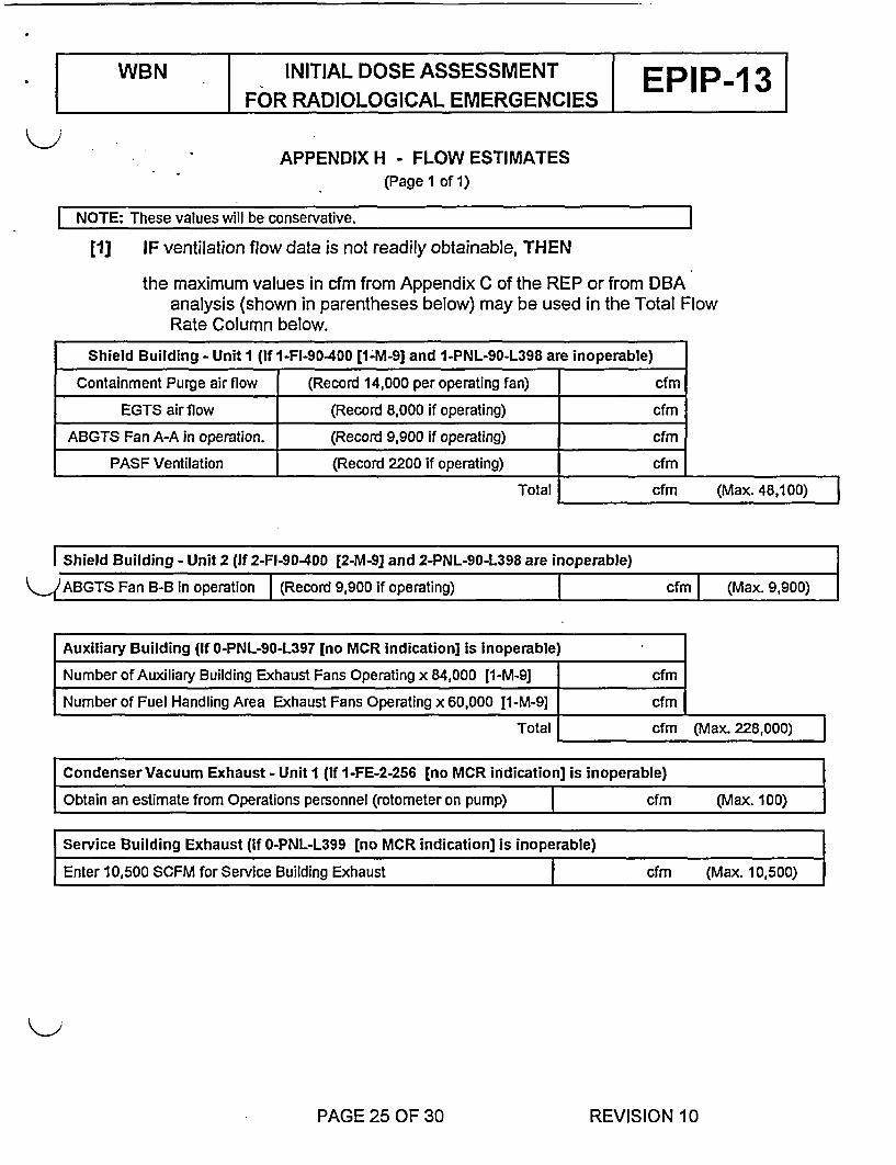
APPENDIX H - FLOW ESTIMATES(Page 1 of 1)
I NOTE: These values will be conservative.
[1] IF ventilation flow data is not readily obtainable, THEN
the maximum values in cfm from Appendix C of the REP or from DBAanalysis (shown in parentheses below) may be used in the Total FlowRate Column below.
Shield Building - Unit I (If 1-FI-90-400 [1-M-9] and 1-PNL-90-L398 are inoperable)
Containment Purge air flow (Record 14,000 per operating fan) cfm
EGTS air flow (Record 8,000 if operating) cfm
ABGTS Fan A-A in operation. (Record 9,900 if operating) cfm
PASF Ventilation (Record 2200 if operating) cfm
K-
Total cfm (Max. 48,100)
I Shield Building - Unit 2 (If 2-FI-90-400 [2-M-9] and 2-PNL-90-L398 are inoperable) l
)ABGTS Fan B-B in operation I (Record 9,900 if operating) cfm (Max. 9,900)
Auxiliary Building (If O-PNL-90-L397 [no MCR indication] is inoperable)
Number of Auxiliary Building Exhaust Fans Operating x 84,000 [1-M-9] cfm
Number of Fuel Handling Area Exhaust Fans Operating x 60,000 [1-M-9] cfm
Total cfm (Max. 228,000)|
Condenser Vacuum Exhaust - Unit I (If I-FE-2-256 [no MCR indication] is inoperable)
Obtain an estimate from Operations personnel (rotometer on pump) I cfm (Max. 100)
Service Building Exhaust (If O-PNL-L399 [no MCR indication] is inoperable)
Enter 10,500 SCFM for Service Building Exhaust cfm (Max. 10,500)
PAGE 25 OF 30 REVISION 10
WBN INITIAL DOSE ASSESSMENT EPIP-13 3FOR RADIOLOGICAL EMERGENCIES
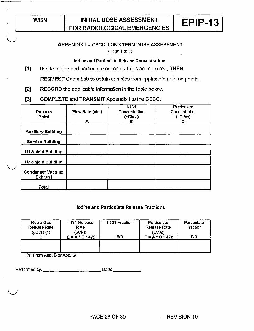
APPENDIX I - CECC LONG TERM DOSE ASSESSMENT(Page 1 of 1)
Iodine and Particulate Release Concentrations
[1] IF site iodine and particulate concentrations are required, THEN
REQUEST Chem Lab to obtain samples from applicable release points.
[2] RECORD the applicable information in the table below.
[3] COMPLETE and TRANSMIT Appendix I to the CECC.1-131 Particulate
Release Flow Rate (cfm) Concentration ConcentrationPoint A(pCi/cc) (gCi/cc)_ _ _ _A B C
Auxiliary Building
Service Building
U1 Shield Buildingc
U2 Shield Building .
Condenser VacuumExhaust
Total
Iodine and Particulate Release Fractions
Noble Gas 1-131 Release I-1 31 Fraction Particulate ParticulateRelease Rate Rate Release Rate Fraction
(±'Ci/s) (1) (pCi/s) (eCis)D E=A* B*472 E/D F=A* C*472 F/D
(1) From App. B or App. G
Performed by: Date:
PAGE 26 OF 30 REVISION 10

WBN INITIAL DOSE ASSESSMENT EPIP 13FOR RADIOLOGICAL EMERGENCIES - 3
APPENDIX J - LOSS OF METEOROLOGICAL DATA(Page 1 of 4)
1.0 PURPOSE
This Appendix provides instructions to ensure appropriate actions are takenby the Shift Manager (SM) for Main Control Room outages of onsitemeteorological data.
2.0 RESPONSIBILITY
Daily meteorological channel checks are performed by the SM to verifyoperability.
If an outage is detected, the SM shall take necessary actions to checkbackup displays, track the outage, and to initiate repair request.
Emergency Planning (EP) Field Support is responsible for operating themeteorological data system and for making the data signal available to theplant.
3.0 MINIMUM REQUIREMENTS
A. The Offsite Dose Calculation Manual (ODCM) requires that two of three windspeed channels, two of three wind direction channels, and one of three airtemperature differences be operable at all times to support estimation ofroutine and accident doses. A special report to the NRC is to be prepared foroutages of more than seven (7) days.
B. Emergency action level event (5.2 tornado) and protective action decisionmaking of the Radiological Emergency Plan (REP) require use ofmeteorological data.
C. R.G. 1.23 "Onsite Meteorological Programs" and ANSI/ANS Standard 3.11-2000 "Determining Meteorological Information at Nuclear Facilities" require a90 percent annual joint data recovery rate of valid wind speed, wind directionand temperature difference.
PAGE 27 OF 30 REVISION 10

WBN INITIAL DOSE ASSESSMENT EPIP 3FOR RADIOLOGICAL EMERGENCIES E 3
APPENDIX J(Page 2 of 4)
LOSS OF METEOROLOGICAL DATA
NOTE l&C should be contacted to fix any problem associated with the ICS display.
[1] IF Met data is unavailable in the Main Control Room or from the ICS Terminals inthe TSC and OSC (METDATA), THEN
OBTAIN Met Data from the MET Tower using the CECC computer terminalin the TSC per Appendix J (page 3 of 4) of this Procedure.
[2] IF the minimum required data listed in Section 3.0 is not available from thesemethods, THEN
DECLARE the system inoperable and begin appropriate tracking, AND
NOTIFY EP Field Support (normal business hours or next working day,whichever is applicable) at x8450.
[3] IF specific Met data is still needed (i.e., EPIP-1, emergency action levels), THEN
the remaining steps for obtaining data should be used in the following order:
[a] CALL the SQN Control Room (843-7860) and request the neededmeteorological information.
[b] REQUEST the Operations Duty Specialist (ODS) to page the dutyCECC Meteorologist. The CECC Meteorologist has backupprocedures to estimate missing data using established relationshipsbetween onsite data and other sources of data.
NOTE This information obtained in step [c] will be from the 10 meterelevation but is still usable.
[c] CALL the Morristown National Weather Service at 9-1-(423)-586-8400and REQUEST the wind speed and wind direction.
[4] DOCUMENT the closure of any tracking initiated, AFTER notification that theMet Tower outage is completed.
PAGE 28 OF 30 REVISION 10

WBN INITIAL DOSE ASSESSMENT EPIP-1 3FOR RADIOLOGICAL EMERGENCIES
APPENDIX J
(Page 3 of 4)
TSC CECC COMPUTER AND PRINTER USE
[1] ENSURE computer terminal is energized (switch is located in front). 1
[2] PRESS the "Return" key twice (repeat step if necessary). a3
[3] TYPE "WBMET' at the "Username" prompt AND
PRESS "Return". 3
NOTE The printer will print the MET data and log off the computer.
[4] TYPE 'TSC" at the "Password" prompt AND
PRESS "Return". D
[5] REPEAT step 2 through 4 for additional MET data as needed.
PAGE 29 OF 30 REVISION 10

WBN INITIAL DOSE ASSESSMENT EPIP-13FOR RADIOLOGICAL EMERGENCIES I
APPENDIX J(Page 4 of 4)
EXAMPLE REPORTWATTS BAR NUCLEAR PLANT
METEORLOGICAL DATA
DATE: 4-OCT-01 TIME: 11:30:48 (Central)REF: 49 LOCATION: CECC COMPUTER
DESCRIPTION INSTRUMENT TS LIMIT DATA (Last 15 min)
1 Om Elevation Operable and 3.5 mphWIND SPEED 46m Elevation Channel Check 5.4 mph
91m Elevation 6.3 mph
WINDDIRECTION
1 Om Elevation46m Elevation91m Elevation
233.7 deg222.4 deg219.3 deg
AIR 10 to 46m 1.1 F*Delta T 10 to 91m 1.9 F*
46 to 91m 0.9 F*
* To calculate Delta T, subtract the Lower elevation temperature valuefrom the higher elevation temperature value (ex: (91m value) - (1lOm value)).
Performers Initials SROs Initials
PAGE 30 OF 30 REVISION 10