Embed Size (px)
Citation preview

OPERATIONMAINTENANCE & PARTS LIST
Waukesha PumpsSP UNIVERSAL II SERIES
Read and understand this manual prior to installing,operating or maintaining this pump.
Effective Date:
September 2005
195-03069
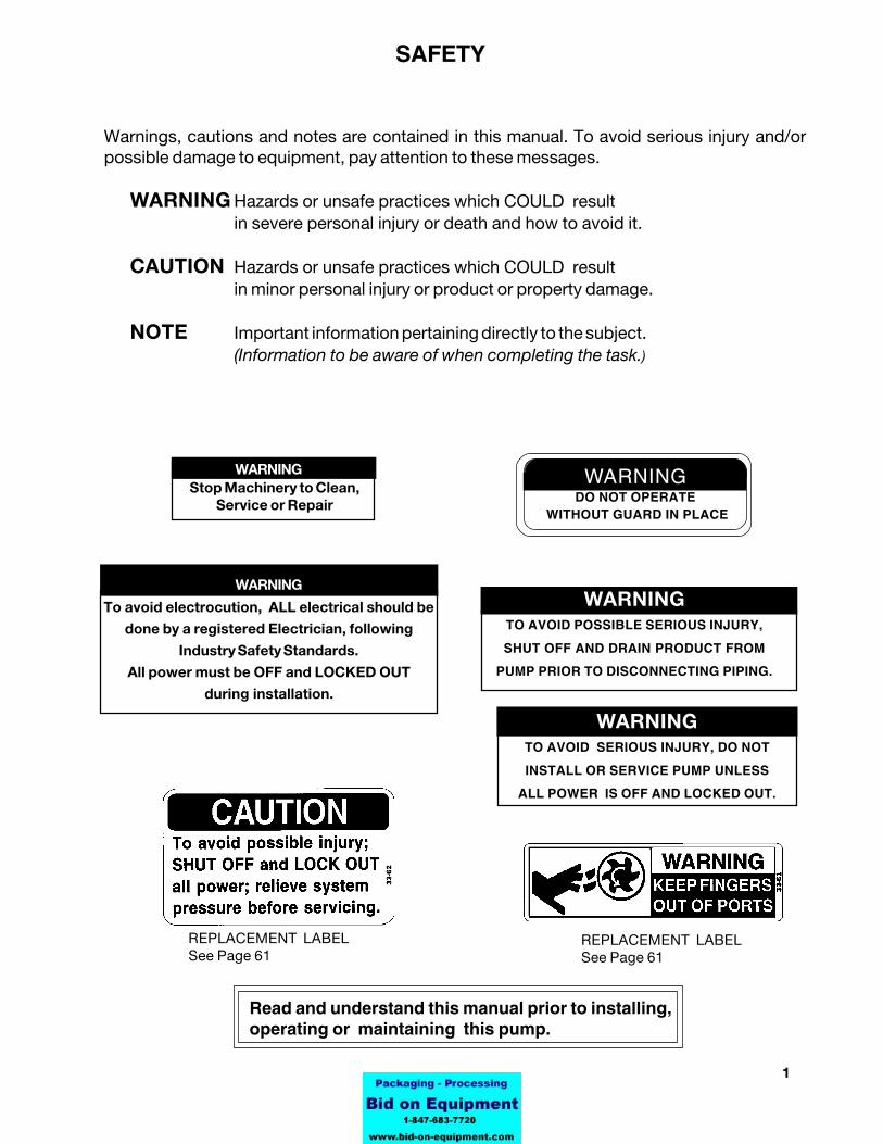
Warnings, cautions and notes are contained in this manual. To avoid serious injury and/orpossible damage to equipment, pay attention to these messages.
WARNING Hazards or unsafe practices which COULD resultin severe personal injury or death and how to avoid it.
CAUTION Hazards or unsafe practices which COULD resultin minor personal injury or product or property damage.
NOTE Important information pertaining directly to the subject.(Information to be aware of when completing the task.)
REPLACEMENT LABELSee Page 61
REPLACEMENT LABELSee Page 61
WARNING
To avoid electrocution, ALL electrical should be
done by a registered Electrician, following
Industry Safety Standards.
All power must be OFF and LOCKED OUT
during installation.
WARNINGTO AVOID SERIOUS INJURY, DO NOT
INSTALL OR SERVICE PUMP UNLESS
ALL POWER IS OFF AND LOCKED OUT.
WARNINGTO AVOID POSSIBLE SERIOUS INJURY,
SHUT OFF AND DRAIN PRODUCT FROM
PUMP PRIOR TO DISCONNECTING PIPING.
WARNINGDO NOT OPERATE
WITHOUT GUARD IN PLACE
Stop Machinery to Clean,Service or Repair
WARNING
Read and understand this manual prior to installing,operating or maintaining this pump.
SAFETY
2 95-03069 September 2005
SECTION Page SECTION Page
TABLE OF CONTENTS
Safety .......................................................... 1
I Receiving and Warranty......... ................ 3Factory Inspection ...................................... 3Receiving Inspection .................................. 3Loss or Damage .......................................... 3
Introduction ............................................... 5
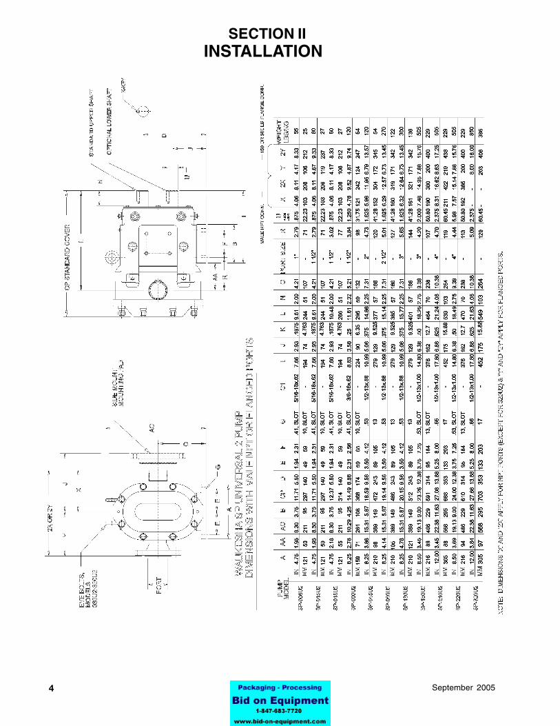
ll Installation.................................... ........ 4-9Basic Dimensions ....................................... 4
lll Start-up Check List ............................ .. 10
IV Troubleshooting a Pump System ... ...... 11-14
V Operation ...................................... ...... 15Lubrication ................................................... 15
Vl Maintenance .................................... .... 16Visual Checks ......................................... 16Feel Checks ............................................. 17
Annual Maintenance ................................. 18
VlI Factory Reconditioning .........................19
Vlll Disassembly ProceduresFluid Head Removal ................................ 20Cover Removal ........................................ 20Rotor Removal ......................................... 20Shaft, Bearings and Gear Removal ........ 21-23
IX Assembly ProceduresShaft Assembly
Front Bearing ........................................... 24Rear Bearing, All Models ........................ 25
Gear Case Assembly .................................. 26
Shims - All Models .................................. 26Shaft Installation (All Models) ................. 26Bearing Retainer Adjustment .................. 27Rear Seal Assembly ................................ 27
Timing Gear and Cover Assembly ............. 28
Proper Clearances ...................................... 29Back Face ............................................... 29Rotor to Body ........................................... 29Front Face ............................................... 29
Seals ........................................................... 30Basic Seal Assembly ................................. 31Fluid Head Assembly ................................ 32
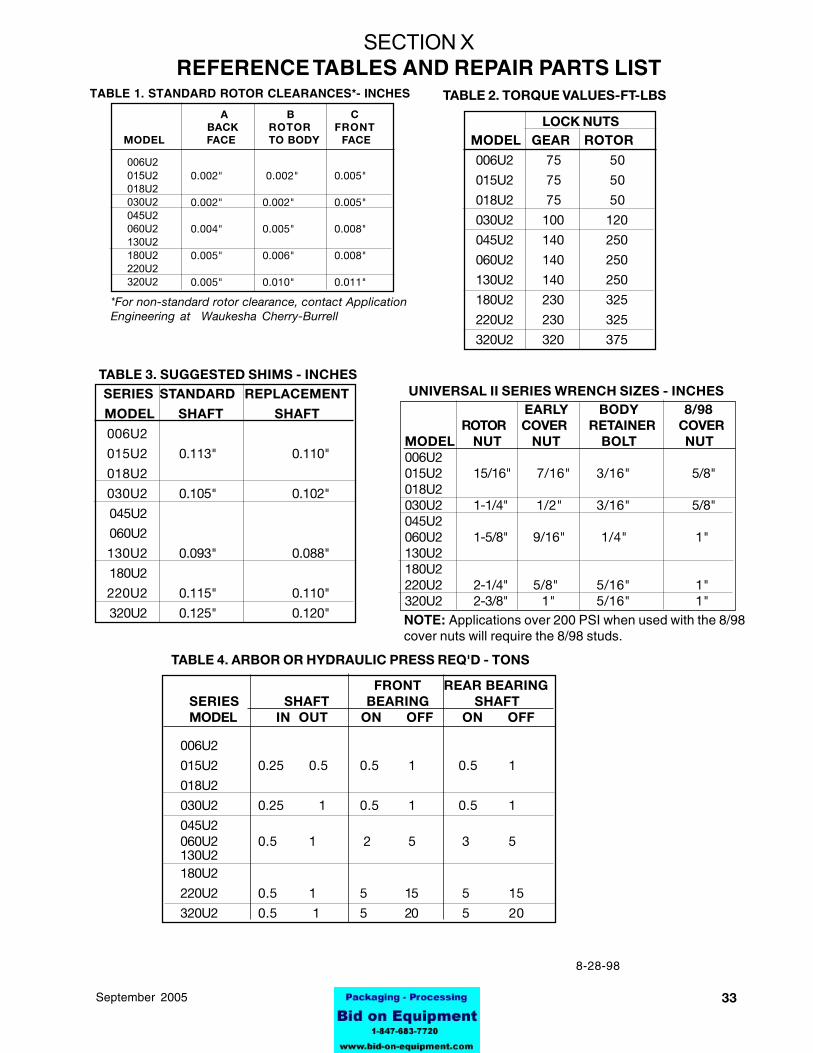
X Reference Tables .Table 1. Standard Rotor Clearance ............ 33Table 2. Assembly Torque Values ............. 33Wrench Sizes .............................................. 33Table 3. Suggested Shims ......................... 33Table 4. Hydraulic Press Tonnage ............. 33
XI Universal II Parts ListingO-ring Index ............................................. 34Complete Pump Parts Listing ................. 35
Special Ordering NoteOptional Pump Features ............................ 36
Illustrated Parts ListsStandard Pumps and Stainless Steel Pumps
Model 006U2 ............................................... 36-37Model 015U2 ............................................... 38-39Model 018U2 ............................................... 40-41Model 030U2 ............................................... 42-43Model 045U2 ............................................... 44-45Model 060U2 ............................................... 46-47Model 130U2 ............................................... 48-49Model 180U2 ............................................... 50-51Model 220U2 ............................................... 52-53Model 320U2 ............................................... 54-55
Mechanical Seals .................................................. 56-60
Warning Label Replacement ............................. 61
Parts Ordering ..................................................... 62Equipment InformationHow to Order PartsHow to Return Parts
395-03069September 2005
FACTORY INSPECTIONEach WAUKESHA pump is shipped completely assembled, lubricated and ready for use.(See OPERATION on page 15). The WAUKESHA pump is a precision product, designed to provide long,trouble-free service in a properly designed system with normal maintenance.
RECEIVING INSPECTIONPorts are rubber capped at the factory to keep out foreign objects. If covers are missing or damaged, athorough inspection of fluid head, by removing pump cover, is recommended. Be sure pumping head isclean and free of foreign material before rotating shaft.
LOSS OR DAMAGEIf your pump has been lost or damaged in transit, file a claim at once with the delivering carrier and askfor an Inspector to call. The carrier has signed the Bill of Lading acknowledging that the shipment hasbeen received from us in good condition.We will of course assist you in every way in collecting claims for loss, or damage, however, we are notresponsible for the collection of claims or replacement of material.
WARRANTYPlease read the Warranty statement to correctly determine if you have a claim. In warranty claims youmust have a "Returned Goods Authorization" (RGA) from the manufacturer before any returns will beaccepted. Your Distributor will help you in a warranty problem. (See back pages for Information required)
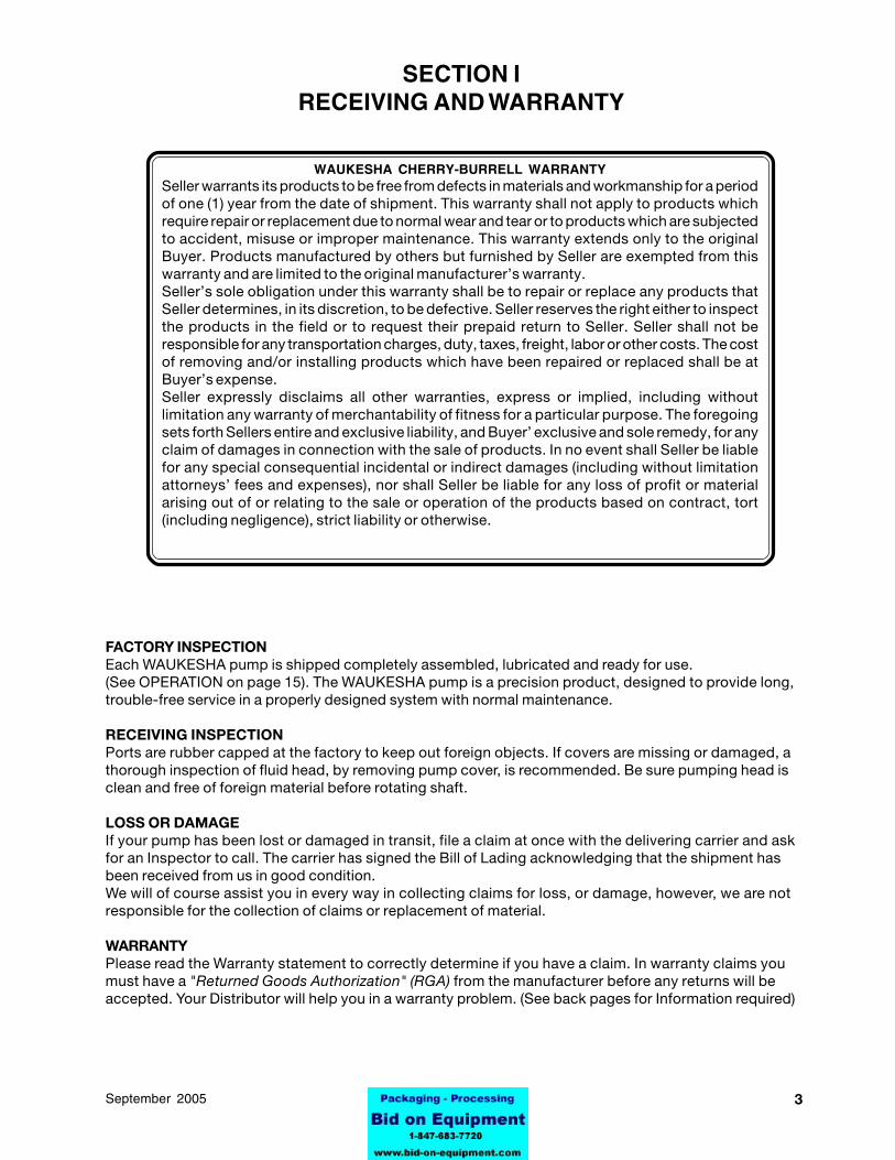
WAUKESHA CHERRY-BURRELL WARRANTYSeller warrants its products to be free from defects in materials and workmanship for a periodof one (1) year from the date of shipment. This warranty shall not apply to products whichrequire repair or replacement due to normal wear and tear or to products which are subjectedto accident, misuse or improper maintenance. This warranty extends only to the originalBuyer. Products manufactured by others but furnished by Seller are exempted from thiswarranty and are limited to the original manufacturer’s warranty.Seller’s sole obligation under this warranty shall be to repair or replace any products thatSeller determines, in its discretion, to be defective. Seller reserves the right either to inspectthe products in the field or to request their prepaid return to Seller. Seller shall not beresponsible for any transportation charges, duty, taxes, freight, labor or other costs. The costof removing and/or installing products which have been repaired or replaced shall be atBuyer’s expense.Seller expressly disclaims all other warranties, express or implied, including withoutlimitation any warranty of merchantability of fitness for a particular purpose. The foregoingsets forth Sellers entire and exclusive liability, and Buyer’ exclusive and sole remedy, for anyclaim of damages in connection with the sale of products. In no event shall Seller be liablefor any special consequential incidental or indirect damages (including without limitationattorneys’ fees and expenses), nor shall Seller be liable for any loss of profit or materialarising out of or relating to the sale or operation of the products based on contract, tort(including negligence), strict liability or otherwise.
SECTION IRECEIVING AND WARRANTY
4 95-03069 September 2005
SECTION IIINSTALLATION
595-03069September 2005
PUMP INSTALLATIONThe installation of your Waukesha pump and its piping system should follow the practices described togive optimum performance, and be in accordance with local codes and restrictions.
All system equipment, such as motors, sheaves, drive couplings, speed reducers, etc., must be properlysized to insure satisfactory operation of your Waukesha pump within its limits.
CAUTION: Waukesha pumps are positive displacement, low slip design and will be severely damaged ifoperated with closed valves in discharge or inlet lines. Pump warranty is not valid for damages caused bya hydraulic overload from operation or start-up with a closed valve in the system.
WARNINGFull coupling guards must be installed to isolate operators and maintenancepersonnel from rotating components. Coupling guards are provided withWaukesha pumps as a part of a complete pump and drive package.
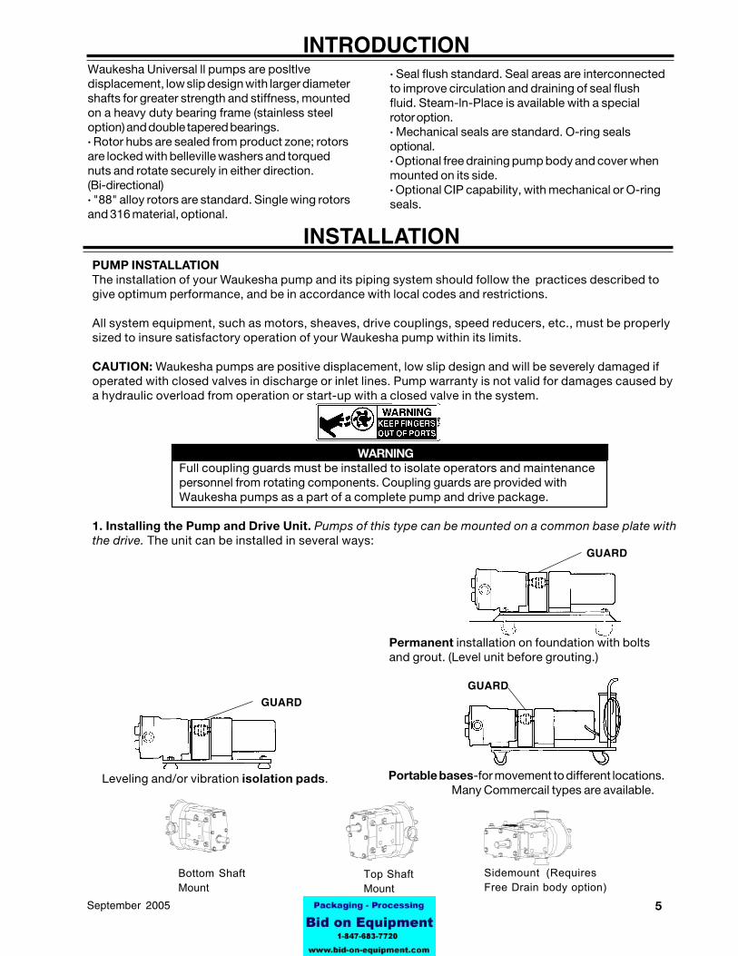
1. Installing the Pump and Drive Unit. Pumps of this type can be mounted on a common base plate withthe drive. The unit can be installed in several ways:
Waukesha Universal ll pumps are posltlvedisplacement, low slip design with larger diametershafts for greater strength and stiffness, mountedon a heavy duty bearing frame (stainless steeloption) and double tapered bearings.· Rotor hubs are sealed from product zone; rotorsare locked with belleville washers and torquednuts and rotate securely in either direction.(Bi-directional)· "88" alloy rotors are standard. Single wing rotorsand 316 material, optional.
· Seal flush standard. Seal areas are interconnectedto improve circulation and draining of seal flushfluid. Steam-ln-Place is available with a specialrotor option.· Mechanical seals are standard. O-ring sealsoptional.· Optional free draining pump body and cover whenmounted on its side.· Optional CIP capability, with mechanical or O-ringseals.
INTRODUCTION
Bottom ShaftMount
Sidemount (RequiresFree Drain body option)
INSTALLATION
Top ShaftMount
Leveling and/or vibration isolation pads. Portable bases-for movement to different locations.Many Commercail types are available.
GUARD
GUARD
Permanent installation on foundation with boltsand grout. (Level unit before grouting.)
GUARD
6 95-03069 September 2005
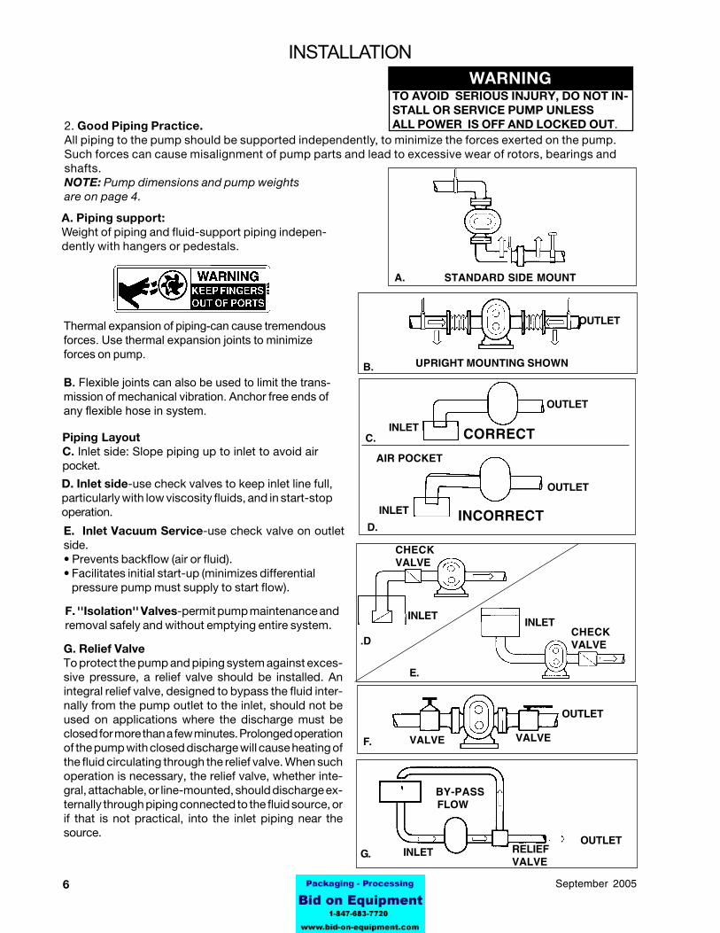
A. Piping support:Weight of piping and fluid-support piping indepen-dently with hangers or pedestals.
2. Good Piping Practice.All piping to the pump should be supported independently, to minimize the forces exerted on the pump.Such forces can cause misalignment of pump parts and lead to excessive wear of rotors, bearings andshafts.NOTE: Pump dimensions and pump weightsare on page 4.
INLETINLET
OUTLET
OUTLET
BY-PASS FLOW
OUTLET
STANDARD SIDE MOUNT
CORRECT
AIR POCKET
UPRIGHT MOUNTING SHOWN
RELIEFVALVE
INLET
VALVE VALVE
G.
F.
INCORRECT
OUTLET
OUTLET
INLET
A.
B.
C.INLET
D.
E.
.D
D. Inlet side-use check valves to keep inlet line full,particularly with low viscosity fluids, and in start-stopoperation.
E. Inlet Vacuum Service-use check valve on outletside.• Prevents backflow (air or fluid).• Facilitates initial start-up (minimizes differential pressure pump must supply to start flow).
F. ''Isolation'' Valves-permit pump maintenance andremoval safely and without emptying entire system.
Piping LayoutC. Inlet side: Slope piping up to inlet to avoid airpocket.
CHECKVALVE
CHECKVALVE
WARNINGTO AVOID SERIOUS INJURY, DO NOT IN-STALL OR SERVICE PUMP UNLESSALL POWER IS OFF AND LOCKED OUT.
INSTALLATION
Thermal expansion of piping-can cause tremendousforces. Use thermal expansion joints to minimizeforces on pump.
B. Flexible joints can also be used to limit the trans-mission of mechanical vibration. Anchor free ends ofany flexible hose in system.
G. Relief ValveTo protect the pump and piping system against exces-sive pressure, a relief valve should be installed. Anintegral relief valve, designed to bypass the fluid inter-nally from the pump outlet to the inlet, should not beused on applications where the discharge must beclosed for more than a few minutes. Prolonged operationof the pump with closed discharge will cause heating ofthe fluid circulating through the relief valve. When suchoperation is necessary, the relief valve, whether inte-gral, attachable, or line-mounted, should discharge ex-ternally through piping connected to the fluid source, orif that is not practical, into the inlet piping near thesource.
795-03069September 2005
WARNINGTO AVOID SERIOUS INJURY, DO NOTINSTALL OR SERVICE PUMP UNLESSALL POWER IS OFF AND LOCKED OUT.
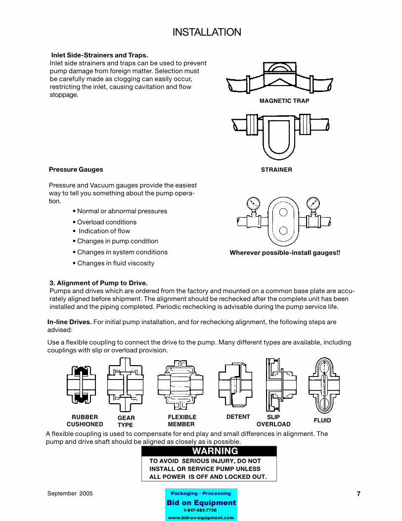
Inlet Side-Strainers and Traps.Inlet side strainers and traps can be used to preventpump damage from foreign matter. Selection mustbe carefully made as clogging can easily occur,restricting the inlet, causing cavitation and flowstoppage.
MAGNETIC TRAP
Pressure Gauges
Pressure and Vacuum gauges provide the easiestway to tell you something about the pump opera-tion.
• Normal or abnormal pressures
• Overload conditions• Indication of flow
• Changes in pump condition
• Changes in system conditions
• Changes in fluid viscosity
STRAINER
Wherever possible-install gauges!!
3. Alignment of Pump to Drive.Pumps and drives which are ordered from the factory and mounted on a common base plate are accu-rately aligned before shipment. The alignment should be rechecked after the complete unit has beeninstalled and the piping completed. Periodic rechecking is advisable during the pump service life.
In-line Drives. For initial pump installation, and for rechecking alignment, the following steps areadvised:
Use a flexible coupling to connect the drive to the pump. Many different types are available, includingcouplings with slip or overload provision.
A flexible coupling is used to compensate for end play and small differences in alignment. Thepump and drive shaft should be aligned as closely as is possible.
FLUIDSLIPOVERLOAD
DETENTFLEXIBLEMEMBER
GEARTYPE
RUBBERCUSHIONED
INSTALLATION
8 95-03069 September 2005
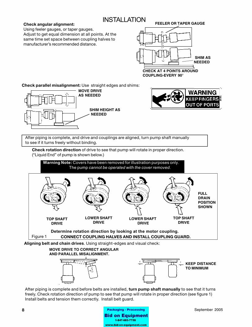
Check angular alignment:Using feeler gauges, or taper gauges.Adjust to get equal dimension at all points. At thesame time set space between coupling halves tomanufacturer’s recommended distance.
FEELER OR TAPER GAUGE
SHIM ASNEEDED
CHECK AT 4 POINTS AROUNDCOUPLING-EVERY 90°
SHIM HEIGHT AS NEEDED
MOVE DRIVEAS NEEDED
Check parallel misalignment: Use straight edges and shims:
After piping is complete, and drive and couplings are aligned, turn pump shaft manuallyto see if it turns freely without binding.
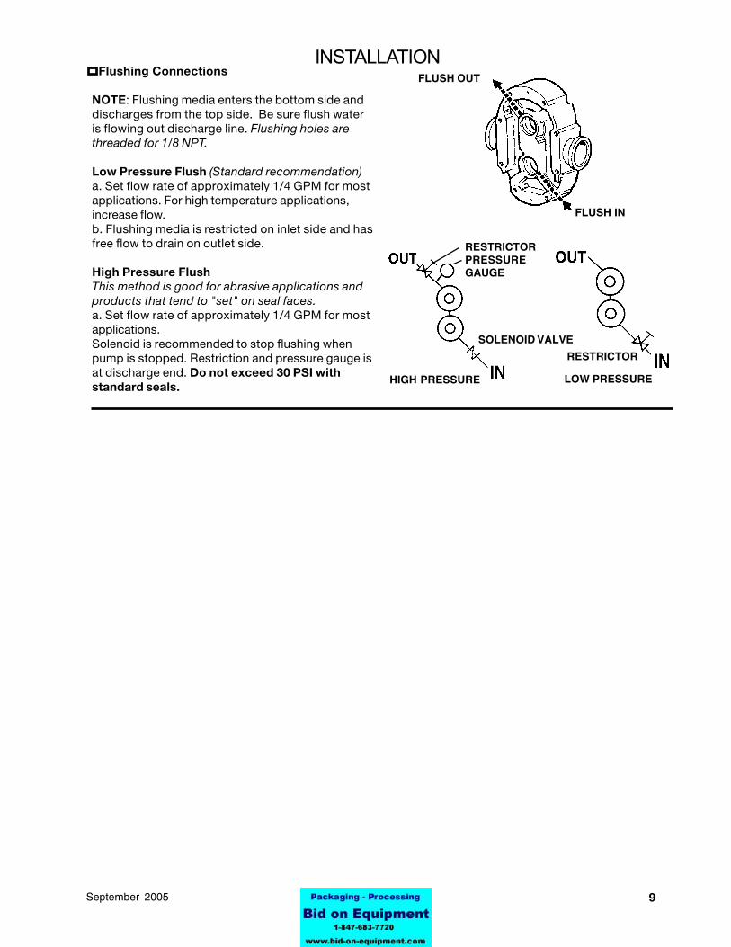
Check rotation direction of drive to see that pump will rotate in proper direction.(“Liquid End” of pump is shown below.)
After piping is complete and before belts are installed, turn pump shaft manually to see that it turnsfreely. Check rotation direction of pump to see that pump will rotate in proper direction (see figure 1)Install belts and tension them correctly. Install belt guard.
MOVE DRIVE TO CORRECT ANGULARAND PARALLEL MISALIGNMENT.
Warning Note: Covers have been removed for illustration purposes only.The pump cannot be operated with the cover removed.
TOP SHAFTDRIVE
Determine rotation direction by looking at the motor coupling.CONNECT COUPLING HALVES AND INSTALL COUPLING GUARD.
TOP SHAFTDRIVE
LOWER SHAFT DRIVE
LOWER SHAFTDRIVE
Figure 1
FULLDRAINPOSITIONSHOWN
INSTALLATION
Aligning belt and chain drives. Using straight-edges and visual check:
KEEP DISTANCETO MINIMUM
995-03069September 2005
FLUSH IN
FLUSH OUT
RESTRICTORPRESSUREGAUGE
SOLENOID VALVE
RESTRICTOR
HIGH PRESSURE LOW PRESSURE
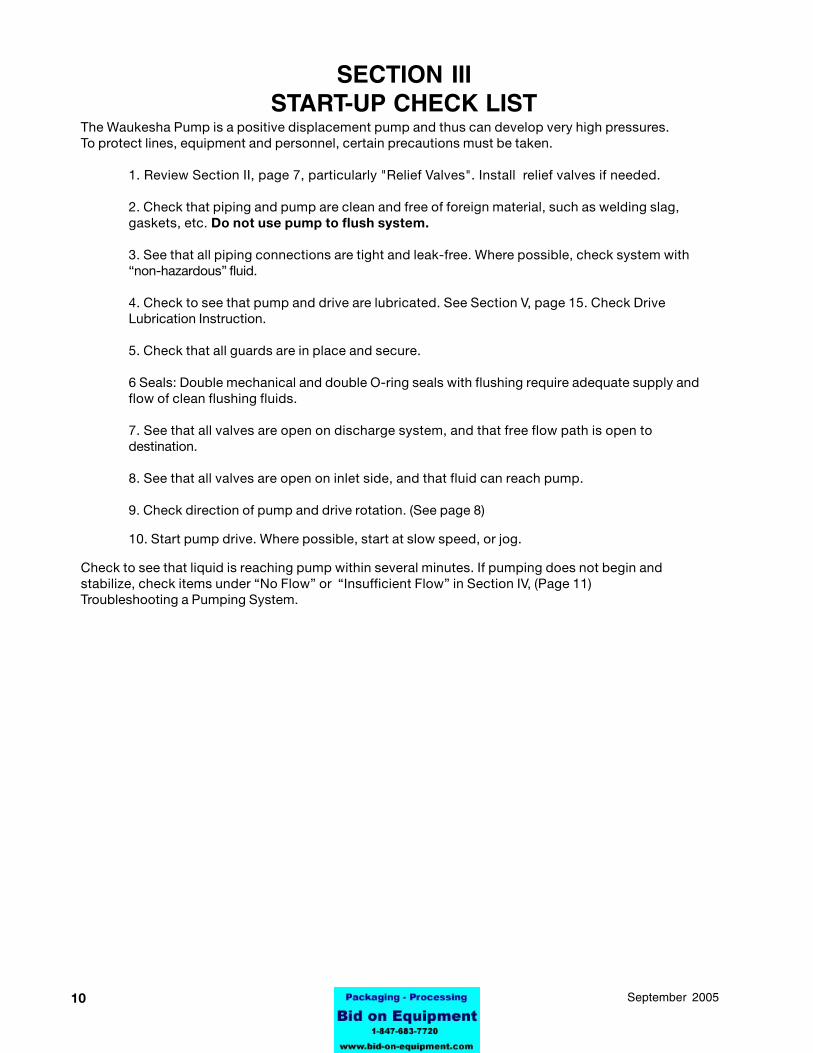
INSTALLATION Flushing Connections
NOTE: Flushing media enters the bottom side anddischarges from the top side. Be sure flush wateris flowing out discharge line. Flushing holes arethreaded for 1/8 NPT.
Low Pressure Flush (Standard recommendation)a. Set flow rate of approximately 1/4 GPM for mostapplications. For high temperature applications,increase flow.b. Flushing media is restricted on inlet side and hasfree flow to drain on outlet side.
High Pressure FlushThis method is good for abrasive applications andproducts that tend to "set" on seal faces.a. Set flow rate of approximately 1/4 GPM for mostapplications.Solenoid is recommended to stop flushing whenpump is stopped. Restriction and pressure gauge isat discharge end. Do not exceed 30 PSI withstandard seals.
10 95-03069 September 2005
SECTION IIISTART-UP CHECK LIST
The Waukesha Pump is a positive displacement pump and thus can develop very high pressures.To protect lines, equipment and personnel, certain precautions must be taken.
1. Review Section II, page 7, particularly "Relief Valves". Install relief valves if needed.
2. Check that piping and pump are clean and free of foreign material, such as welding slag,gaskets, etc. Do not use pump to flush system.
3. See that all piping connections are tight and leak-free. Where possible, check system with“non-hazardous” fluid.
4. Check to see that pump and drive are lubricated. See Section V, page 15. Check DriveLubrication Instruction.
5. Check that all guards are in place and secure.
6 Seals: Double mechanical and double O-ring seals with flushing require adequate supply andflow of clean flushing fluids.
7. See that all valves are open on discharge system, and that free flow path is open todestination.
8. See that all valves are open on inlet side, and that fluid can reach pump.
9. Check direction of pump and drive rotation. (See page 8)
10. Start pump drive. Where possible, start at slow speed, or jog.
Check to see that liquid is reaching pump within several minutes. If pumping does not begin andstabilize, check items under “No Flow” or “Insufficient Flow” in Section IV, (Page 11)Troubleshooting a Pumping System.
1195-03069September 2005
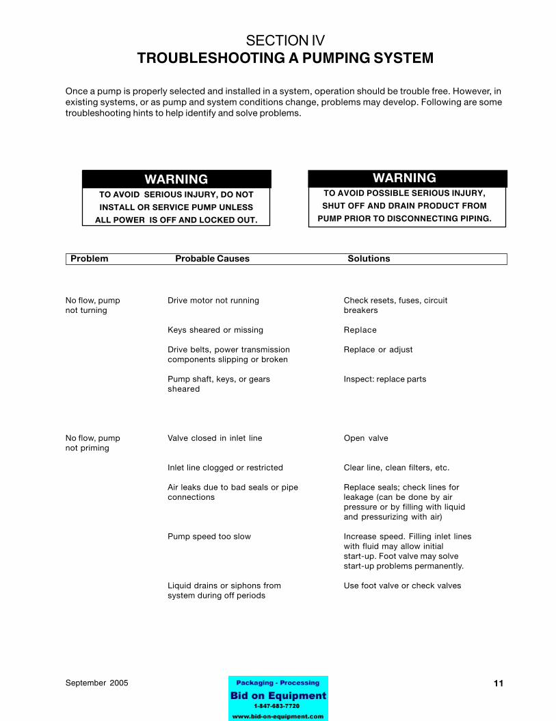
WARNINGTO AVOID SERIOUS INJURY, DO NOT
INSTALL OR SERVICE PUMP UNLESS
ALL POWER IS OFF AND LOCKED OUT.
WARNINGTO AVOID POSSIBLE SERIOUS INJURY,
SHUT OFF AND DRAIN PRODUCT FROM
PUMP PRIOR TO DISCONNECTING PIPING.
No flow, pump Drive motor not running Check resets, fuses, circuitnot turning breakers
Keys sheared or missing Replace
Drive belts, power transmission Replace or adjustcomponents slipping or broken
Pump shaft, keys, or gears Inspect: replace partssheared
No flow, pump Valve closed in inlet line Open valvenot priming
Inlet line clogged or restricted Clear line, clean filters, etc.
Air leaks due to bad seals or pipe Replace seals; check lines forconnections leakage (can be done by air
pressure or by filling with liquidand pressurizing with air)
Pump speed too slow Increase speed. Filling inlet lineswith fluid may allow initialstart-up. Foot valve may solvestart-up problems permanently.
Liquid drains or siphons from Use foot valve or check valvessystem during off periods
SECTION IVTROUBLESHOOTING A PUMPING SYSTEM
Once a pump is properly selected and installed in a system, operation should be trouble free. However, inexisting systems, or as pump and system conditions change, problems may develop. Following are sometroubleshooting hints to help identify and solve problems.
Problem Probable Causes Solutions
12 95-03069 September 2005
Problem Probable Causes Solutions
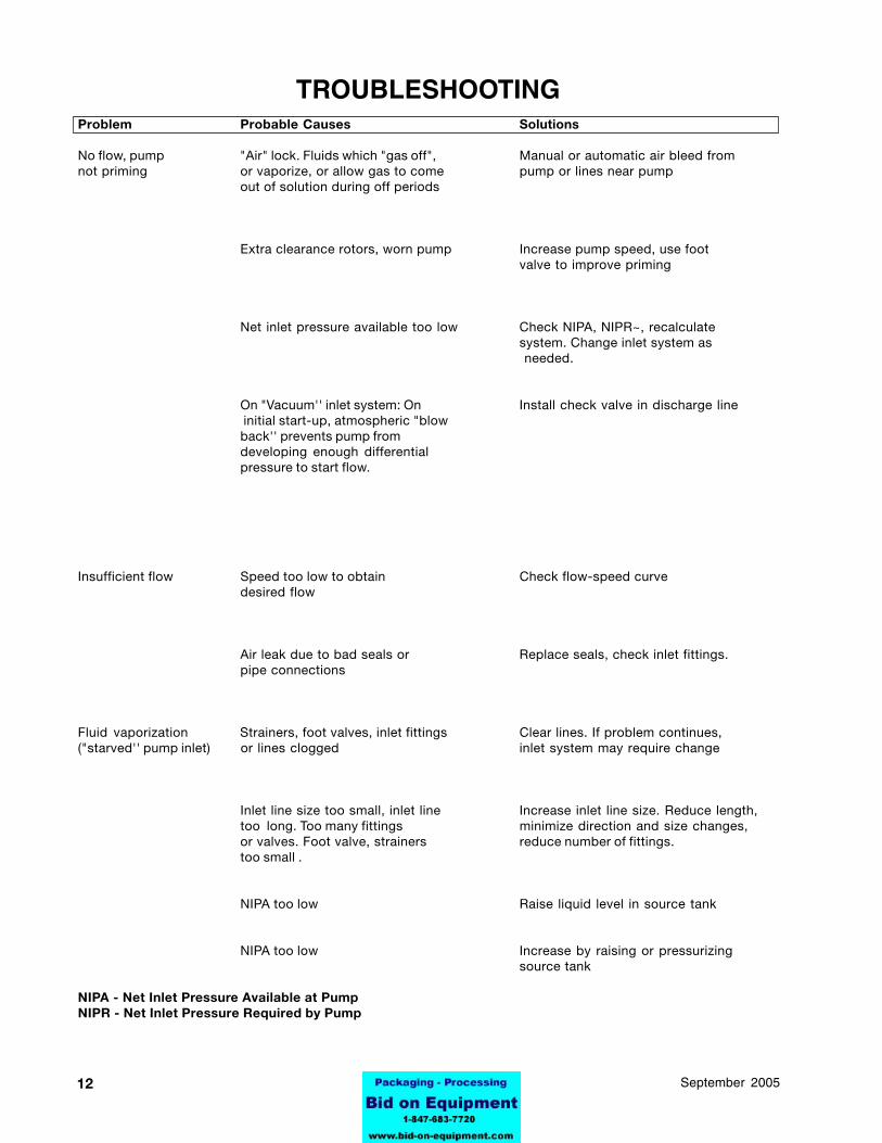
No flow, pump "Air" lock. Fluids which "gas off", Manual or automatic air bleed fromnot priming or vaporize, or allow gas to come pump or lines near pump
out of solution during off periods
Extra clearance rotors, worn pump Increase pump speed, use footvalve to improve priming
Net inlet pressure available too low Check NIPA, NIPR~, recalculatesystem. Change inlet system as needed.
On "Vacuum'' inlet system: On Install check valve in discharge line initial start-up, atmospheric "blowback'' prevents pump fromdeveloping enough differentialpressure to start flow.
Insufficient flow Speed too low to obtain Check flow-speed curvedesired flow
Air leak due to bad seals or Replace seals, check inlet fittings.pipe connections
Fluid vaporization Strainers, foot valves, inlet fittings Clear lines. If problem continues,("starved'' pump inlet) or lines clogged inlet system may require change
Inlet line size too small, inlet line Increase inlet line size. Reduce length,too long. Too many fittings minimize direction and size changes,or valves. Foot valve, strainers reduce number of fittings.too small .
NIPA too low Raise liquid level in source tank
NIPA too low Increase by raising or pressurizingsource tank
NIPA - Net Inlet Pressure Available at PumpNIPR - Net Inlet Pressure Required by Pump
TROUBLESHOOTING
1395-03069September 2005
Problem Probable Causes Solutions
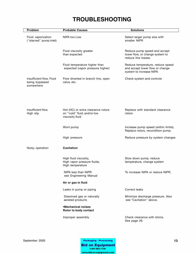
Fluid vaporization NIPA too Low Select larger pump size with(''starved'' pump inlet) smaller NIPR
Fluid viscosity greater Reduce pump speed and acceptthan expected lower flow, or change system to
reduce line losses.
Fluid temperature higher than Reduce temperature, reduce speed expected (vapor pressure higher) and accept lower flow or change
system to increase NIPA
Insufficient flow. Fluid Flow diverted in branch line, open Check system and controlsbeing bypassed valve, etc.somewhere
Insufficient flow. Hot (HC) or extra clearance rotors Replace with standard clearanceHigh slip on '"cold'' fluid, and/or low rotors
viscosity fluid
Worn pump Increase pump speed (within limits).Replace rotors, recondition pump.
High pressure Reduce pressure by system changes
Noisy operation Cavitation
High fluid viscosity, Slow down pump, reduceHigh vapor pressure fluids, temperature, change systemHigh temperature
NIPA less than NIPR To increase NIPA or reduce NIPR, see Engineering Manual
Air or gas in fluid
Leaks in pump or piping Correct leaks
Dissolved gas or naturally Minimize discharge pressure. Also aerated products see "Cavitation'' above.
•Mechanical noisesRotor to body contact
Improper assembly Check clearance with shims.See page 26.
TROUBLESHOOTING
14 95-03069 September 2005
TROUBLESHOOTINGProblem Probable Causes Solutions
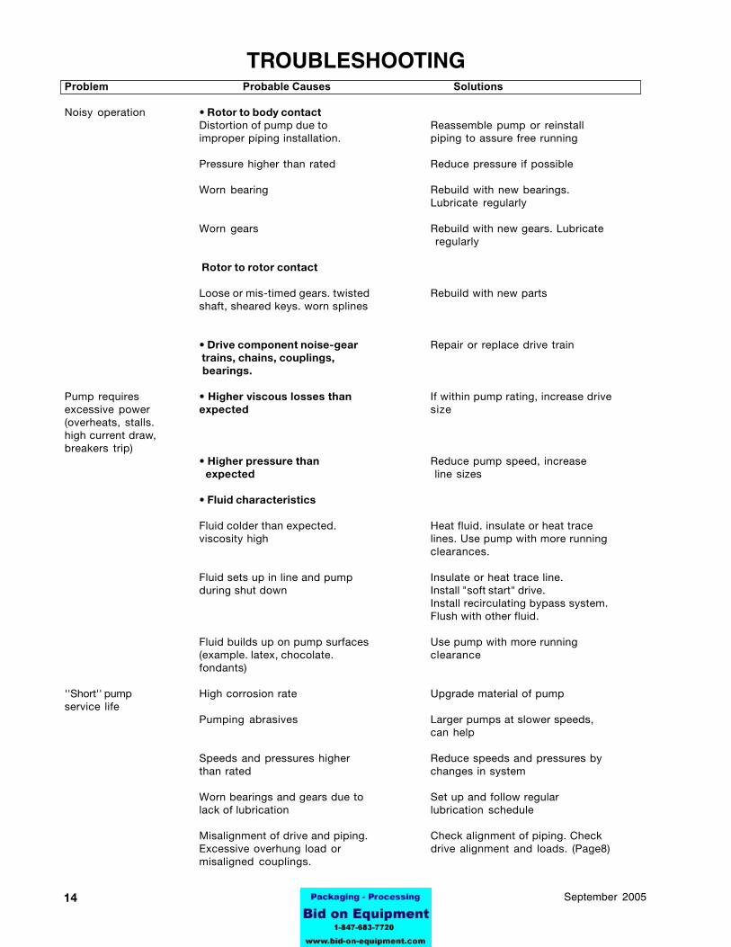
Noisy operation • Rotor to body contactDistortion of pump due to Reassemble pump or reinstallimproper piping installation. piping to assure free running
Pressure higher than rated Reduce pressure if possible
Worn bearing Rebuild with new bearings.Lubricate regularly
Worn gears Rebuild with new gears. Lubricate regularly
Rotor to rotor contact
Loose or mis-timed gears. twisted Rebuild with new partsshaft, sheared keys. worn splines
• Drive component noise-gear Repair or replace drive train trains, chains, couplings, bearings.
Pump requires • Higher viscous losses than If within pump rating, increase driveexcessive power expected size(overheats, stalls.high current draw,breakers trip)
• Higher pressure than Reduce pump speed, increase expected line sizes
• Fluid characteristics
Fluid colder than expected. Heat fluid. insulate or heat traceviscosity high lines. Use pump with more running
clearances.
Fluid sets up in line and pump Insulate or heat trace line.during shut down Install "soft start" drive.
Install recirculating bypass system.Flush with other fluid.
Fluid builds up on pump surfaces Use pump with more running(example. latex, chocolate. clearancefondants)
''Short'' pump High corrosion rate Upgrade material of pumpservice life
Pumping abrasives Larger pumps at slower speeds,can help
Speeds and pressures higher Reduce speeds and pressures bythan rated changes in system
Worn bearings and gears due to Set up and follow regularlack of lubrication lubrication schedule
Misalignment of drive and piping. Check alignment of piping. CheckExcessive overhung load or drive alignment and loads. (Page8)misaligned couplings.
1595-03069September 2005
OILMicro-Plate #140
-10° to 350° F. (-23° to 177° C.)
GREASESilicone -20° to 5° F.( -29° to 15° C.)
Micro-Plate #555 (5° to 350° F.(-15° to 177° C.)
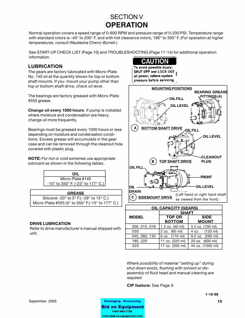
LUBRICATIONThe gears are factory lubricated with Micro-PlateNo. 140 oil at the quantity shown for top or bottomshaft mounts. If you mount your pump other thantop or bottom shaft drive, check oil level.
The bearings are factory greased with Micro-Plate#555 grease.
Change oil every 1000 hours. If pump is installedwhere moisture and condensation are heavy,change oil more frequently.
Bearings must be greased every 1000 hours or lessdepending on moisture and condensation condi-tions. Excess grease will accumulate in the gearcase and can be removed through the cleanout holecovered with plastic plug.
NOTE: For hot or cold extremes use appropriatelubricant as shown in the following tables.
Normal operation covers a speed range of 0-600 RPM and pressure range of 0-200 PSI. Temperature rangewith standard rotors is -40° to 200° F. and with hot clearance rotors, 180° to 300° F. (For operation at highertemperatures, consult Waukesha Cherry-Burrell.)
See START-UP CHECK LIST (Page 10) and TROUBLESHOOTING (Page 11-14) for additional operationinformation.
SECTION VOPERATION
1-16-96
OIL CAPACITY (GEARS)SHAFT
MODEL TOP OR SIDE BOTTOM MOUNT
006, 015, 018 1.3 oz. (40 ml) 3.3 oz. (100 ml)030 2 oz. (60 ml) 4 oz. (120 ml)045, 060, 130 6 oz. (170 ml) 9.5 oz. (280 ml)180, 220 11 oz. (320 ml) 20 oz. (600 ml)320 17 oz. (500 ml) 44 oz. (1300 ml)
Where possibility of material "setting up" duringshut down exists, flushing with solvent or dis-assembly of fluid head and manual cleaning arerequired.
CIP feature: See Page 9
OILDRAIN
DRIVE LUBRICATIONRefer to drive manufacturer's manual shipped withunit.
(Left hand or right hand shaftas viewed from the front)
OIL LEVEL
CLEANOUTPLUG
OIL FILL
OIL FILL
OIL LEVEL
TOP SHAFT DRIVE
OIL FILLBOTTOM SHAFT DRIVE
OIL LEVEL
BEARING GREASEFITTINGS (4)
FRONT
MOUNTING POSITIONS
A
B
C SIDEMOUNT DRIVE
16 95-03069 September 2005
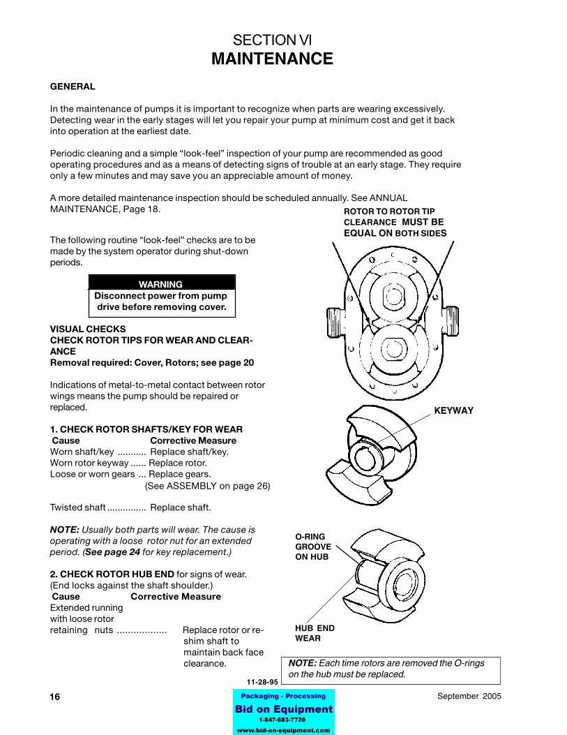
The following routine “look-feel” checks are to bemade by the system operator during shut-downperiods.
WARNINGDisconnect power from pump drive before removing cover.
VISUAL CHECKSCHECK ROTOR TIPS FOR WEAR AND CLEAR-ANCERemoval required: Cover, Rotors; see page 20
Indications of metal-to-metal contact between rotorwings means the pump should be repaired orreplaced.
1. CHECK ROTOR SHAFTS/KEY FOR WEAR Cause Corrective MeasureWorn shaft/key ........... Replace shaft/key.Worn rotor keyway ...... Replace rotor.Loose or worn gears ... Replace gears.
Twisted shaft ............... Replace shaft.
NOTE: Usually both parts will wear. The cause isoperating with a loose rotor nut for an extendedperiod. (See page 24 for key replacement.)
2. CHECK ROTOR HUB END for signs of wear.(End locks against the shaft shoulder.) Cause Corrective MeasureExtended runningwith loose rotorretaining nuts .................. Replace rotor or re-
shim shaft tomaintain back faceclearance.
KEYWAY
SECTION VlMAINTENANCE
GENERAL
In the maintenance of pumps it is important to recognize when parts are wearing excessively.Detecting wear in the early stages will let you repair your pump at minimum cost and get it backinto operation at the earliest date.
Periodic cleaning and a simple “look-feel” inspection of your pump are recommended as goodoperating procedures and as a means of detecting signs of trouble at an early stage. They requireonly a few minutes and may save you an appreciable amount of money.
A more detailed maintenance inspection should be scheduled annually. See ANNUALMAINTENANCE, Page 18.
O-RINGGROOVEON HUB
HUB ENDWEAR
NOTE: Each time rotors are removed the O-ringson the hub must be replaced.
11-28-95
(See ASSEMBLY on page 26)
ROTOR TO ROTOR TIPCLEARANCE MUST BEEQUAL ON BOTH SIDES
1795-03069September 2005
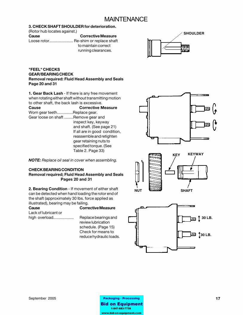
SHOULDER
30 LB.
30 LB.
3. CHECK SHAFT SHOULDER for deterioration.(Rotor hub locates against.)Cause Corrective MeasureLoose rotor..................... Re-shim or replace shaft
to maintain correctrunning clearances.
"FEEL" CHECKSGEAR/BEARING CHECKRemoval required: Fluid Head Assembly and SealsPage 20 and 31
1. Gear Back Lash - If there is any free movementwhen rotating either shaft without transmitting motionto other shaft, the back lash is excessive.Cause Corrective MeasureWorn gear teeth..............Replace gear.Gear loose on shaft ........Remove gear and
inspect key, keywayand shaft. (See page 21)If all are in good condition,reassemble and retightengear retaining nuts tospecified torque. (SeeTable 2. Page 33)
NOTE: Replace oil seal in cover when assembling.
CHECK BEARING CONDITIONRemoval required; Fluid Head Assembly and Seals
Pages 20 and 31
2. Bearing Condition - If movement of either shaftcan be detected when hand loading the rotor end ofthe shaft (approximately 30 Ibs. force applied asillustrated), bearing may be failing.Cause Corrective MeasureLack of lubricant orhigh overload.................. Replace bearings and
review lubricationschedule. (Page 15)Check for means toreduce hydraulic loads.
KEY
SHAFTNUT
KEYWAY
MAINTENANCE
18 95-03069 September 2005
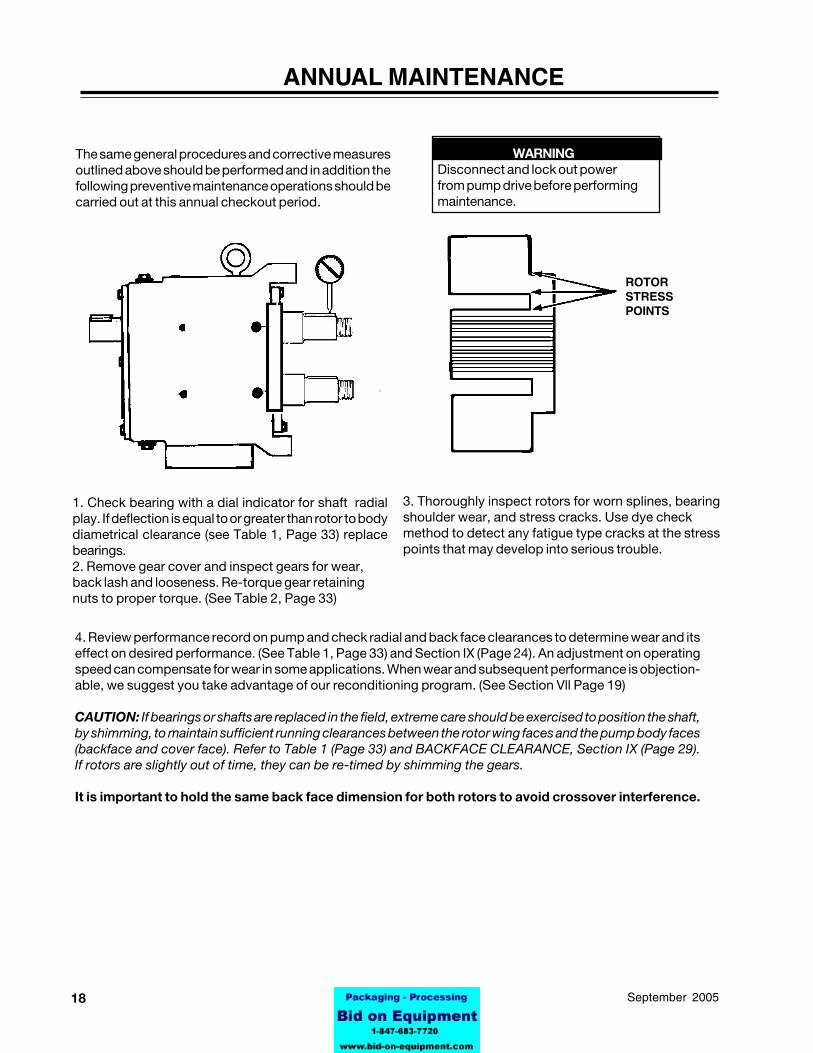
WARNINGDisconnect and lock out powerfrom pump drive before performingmaintenance.
ANNUAL MAINTENANCE
The same general procedures and corrective measuresoutlined above should be performed and in addition thefollowing preventive maintenance operations should becarried out at this annual checkout period.
ROTORSTRESSPOINTS
1. Check bearing with a dial indicator for shaft radialplay. If deflection is equal to or greater than rotor to bodydiametrical clearance (see Table 1, Page 33) replacebearings.2. Remove gear cover and inspect gears for wear,back lash and looseness. Re-torque gear retainingnuts to proper torque. (See Table 2, Page 33)
3. Thoroughly inspect rotors for worn splines, bearingshoulder wear, and stress cracks. Use dye checkmethod to detect any fatigue type cracks at the stresspoints that may develop into serious trouble.
4. Review performance record on pump and check radial and back face clearances to determine wear and itseffect on desired performance. (See Table 1, Page 33) and Section IX (Page 24). An adjustment on operatingspeed can compensate for wear in some applications. When wear and subsequent performance is objection-able, we suggest you take advantage of our reconditioning program. (See Section Vll Page 19)
CAUTION: If bearings or shafts are replaced in the field, extreme care should be exercised to position the shaft,by shimming, to maintain sufficient running clearances between the rotor wing faces and the pump body faces(backface and cover face). Refer to Table 1 (Page 33) and BACKFACE CLEARANCE, Section IX (Page 29).If rotors are slightly out of time, they can be re-timed by shimming the gears.
It is important to hold the same back face dimension for both rotors to avoid crossover interference.
1995-03069September 2005
SECTION VllFACTORY REMANUFACTURING
Waukesha UNIVERSAL pumps are designed to allow them to be factory remanufactured twice and backedwith a new pump warranty each time.Factory remanufactured involves replacement of all worn parts such as shafts, bearings, oil seals, gears, etc.The pump body and cover are re-machined and new rotors are installed.The pumps are stamped R-1 or R-2, after the serial number, designating that they have been remanufacturedonce or twice.
NOTE: It is advisable to contact the factory and furnish the serial number of any pump being considered forremanufacturing.
When pumps require remanufacturing it is recommended that they be returned to Waukesha Cherry-Burrell withproper purchase order. Where this is not practical, a "remanufactured" pump may be ordered in advance of theactual return of the pump being replaced.
While a large stock of remanufactured pumps is maintained, normal delivery of four weeks should beanticipated. In these cases an invoice will be issued for the price of a new pump with credit allowed upon receiptof the old pump at the factory so the net cost will be that of a remanufactured pump.
INTERCHANGEABILITY
All new pumps are identified by a serial number on bearing gear case nameplate and stamped on top of pumpbody. The gear case and body must be kept together as a unit because of back face clearance. The rotors,seals and covers can be interchanged between units.
ALL remanufactured pump parts must be kept together as a unit. These are specially machined and are notinterchangeable.
CAUTION: If new body is replaced in the field, it is most important to check back face and front face clearances(See Table 1, Page 33). Re-shim shafts if required to avoid rotor and cover contact. Both rotors must have thesame clearance to avoid crossover interference.
20 95-03069 September 2005
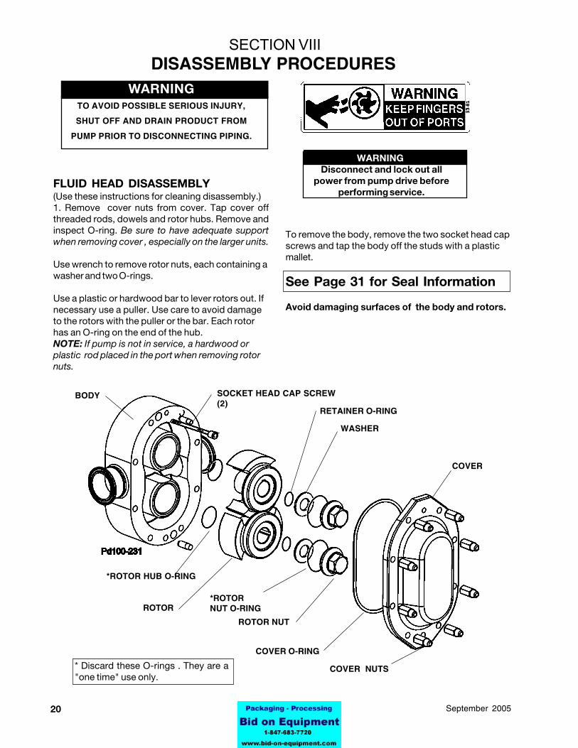
FLUID HEAD DISASSEMBLY(Use these instructions for cleaning disassembly.)1. Remove cover nuts from cover. Tap cover offthreaded rods, dowels and rotor hubs. Remove andinspect O-ring. Be sure to have adequate supportwhen removing cover , especially on the larger units.
Use wrench to remove rotor nuts, each containing awasher and two O-rings.
Use a plastic or hardwood bar to lever rotors out. Ifnecessary use a puller. Use care to avoid damageto the rotors with the puller or the bar. Each rotorhas an O-ring on the end of the hub.NOTE: If pump is not in service, a hardwood orplastic rod placed in the port when removing rotornuts.
To remove the body, remove the two socket head capscrews and tap the body off the studs with a plasticmallet.
See Page 31 for Seal Information
Avoid damaging surfaces of the body and rotors.
*ROTOR HUB O-RING
ROTOR
BODY
SECTION VIIIDISASSEMBLY PROCEDURES
WARNINGDisconnect and lock out all
power from pump drive beforeperforming service.
WARNINGTO AVOID POSSIBLE SERIOUS INJURY,
SHUT OFF AND DRAIN PRODUCT FROM
PUMP PRIOR TO DISCONNECTING PIPING.
SOCKET HEAD CAP SCREW(2)
RETAINER O-RING
WASHER
COVER
COVER NUTS
COVER O-RING
ROTOR NUT
*ROTORNUT O-RING
* Discard these O-rings . They are a"one time" use only.

2195-03069September 2005
REMOVE SHAFTS, BEARINGS ANDGEARS - ALL MODELS
GEAR CASE
1. Remove oil drain plug and drain oil.
2. Remove cap screws from gear case cover.
3. Pull cover off shaft extension. If cover sticks, use soft hammer to loosen it.
4. Scrape silicone sealant from gear case and cover.
5. Remove oil seal from cover with an arbor press and discard.
6. Straighten locking tab of lock washers.
LOCK WASHER
LOCKWASHER
CAP SCREWAND WASHER
DISASSEMBLY PROCEDURES
GEAR CASE COVER
OIL DRAIN PLUG
SILICONE SEALANT
OIL SEAL
22 95-03069 September 2005
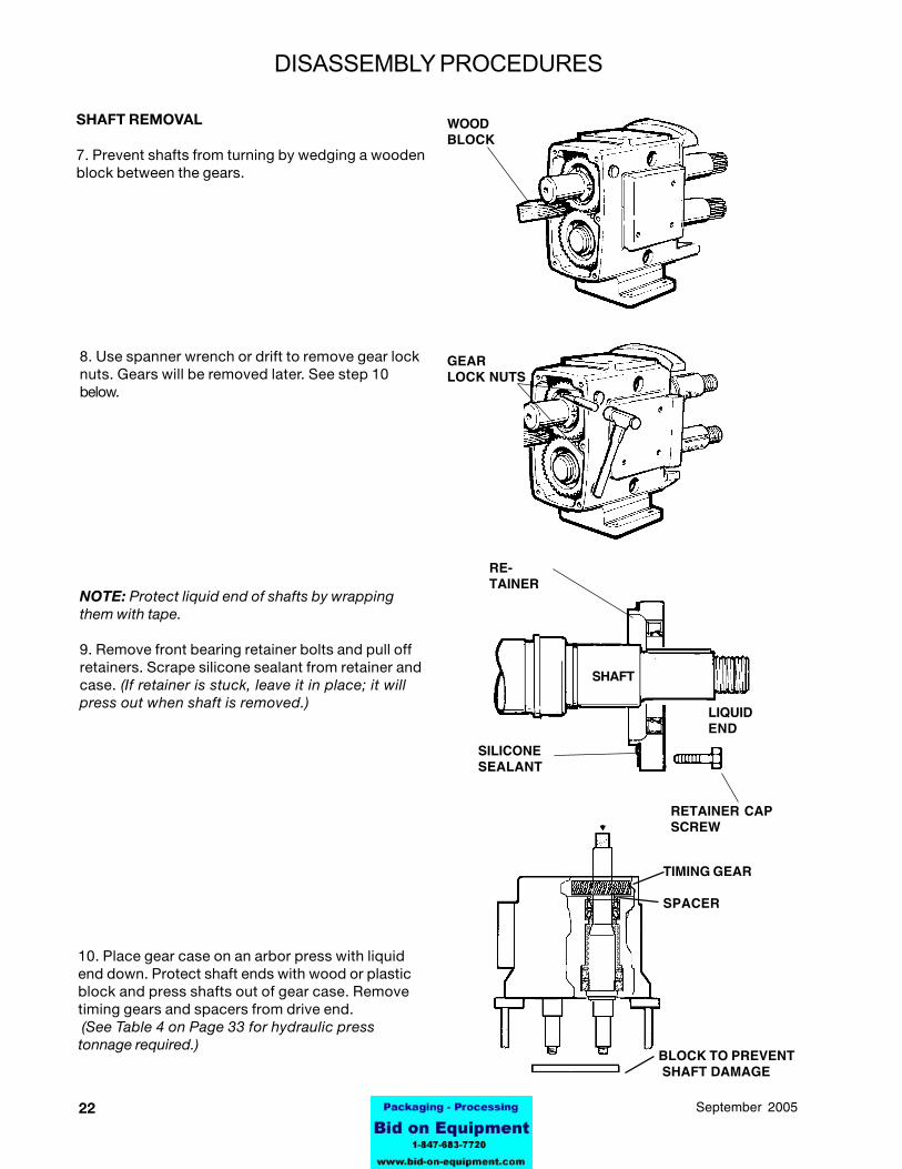
SHAFT REMOVAL
7. Prevent shafts from turning by wedging a woodenblock between the gears.
RE-TAINER
LIQUIDEND
SILICONESEALANT
WOODBLOCK
RETAINER CAPSCREW
GEARLOCK NUTS
BLOCK TO PREVENT SHAFT DAMAGE
SHAFT
TIMING GEAR
SPACER
10. Place gear case on an arbor press with liquidend down. Protect shaft ends with wood or plasticblock and press shafts out of gear case. Removetiming gears and spacers from drive end. (See Table 4 on Page 33 for hydraulic presstonnage required.)
NOTE: Protect liquid end of shafts by wrappingthem with tape.
9. Remove front bearing retainer bolts and pull offretainers. Scrape silicone sealant from retainer andcase. (If retainer is stuck, leave it in place; it willpress out when shaft is removed.)
8. Use spanner wrench or drift to remove gear locknuts. Gears will be removed later. See step 10below.
DISASSEMBLY PROCEDURES
2395-03069September 2005
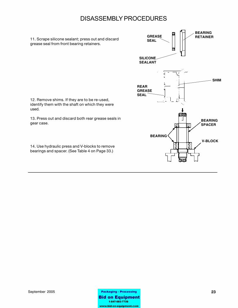
REARGREASESEAL
BEARINGRETAINER
BEARINGSPACER
V-BLOCK
SHIM
SILICONESEALANT
GREASESEAL
BEARING
11. Scrape silicone sealant; press out and discardgrease seal from front bearing retainers.
12. Remove shims. If they are to be re-used,identify them with the shaft on which they wereused.
13. Press out and discard both rear grease seals ingear case.
14. Use hydraulic press and V-blocks to removebearings and spacer. (See Table 4 on Page 33.)
DISASSEMBLY PROCEDURES
24 95-03069 September 2005
SECTION IXASSEMBLY PROCEDURES
SPACER
CUP
RADIUS
SPACER
CONE AND ROLLER
CONE AND ROLLER
CUP
GREASE
CONEAND ROLLER
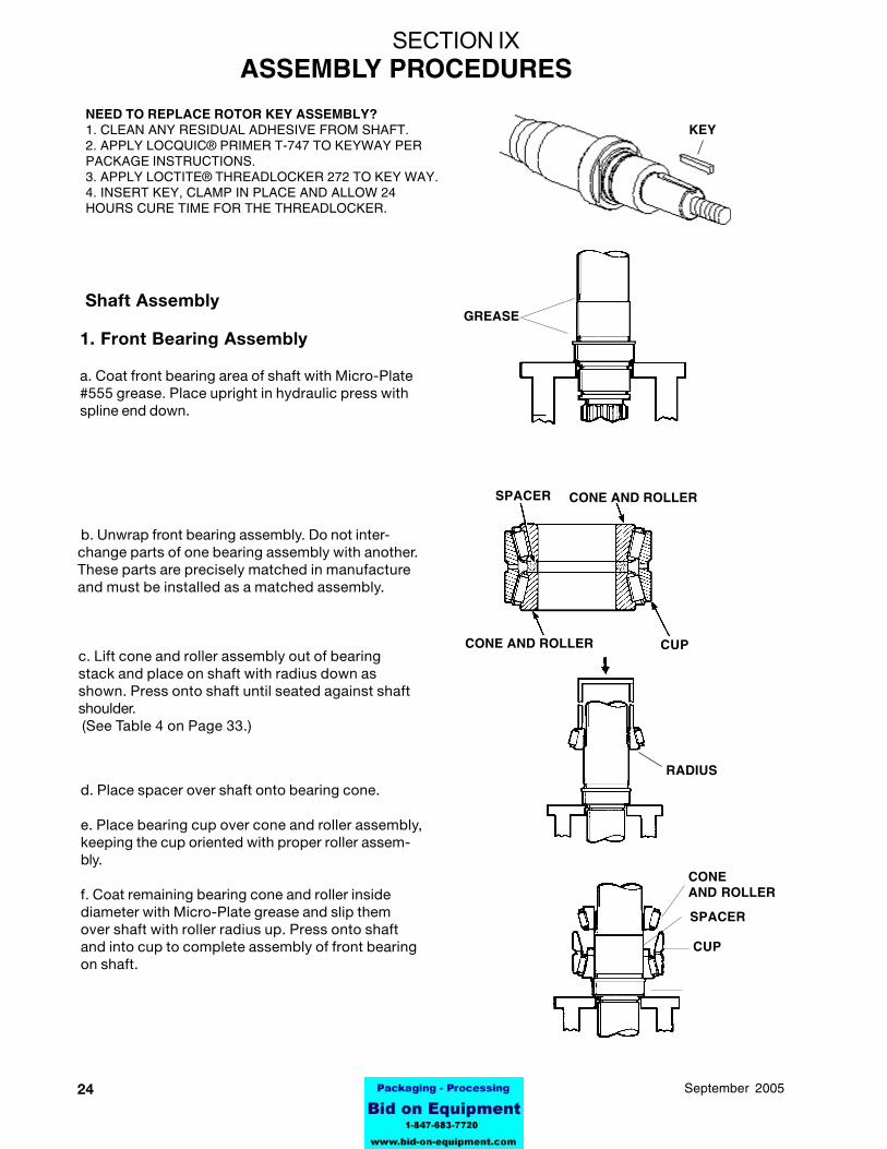
d. Place spacer over shaft onto bearing cone.
e. Place bearing cup over cone and roller assembly,keeping the cup oriented with proper roller assem-bly.
f. Coat remaining bearing cone and roller insidediameter with Micro-Plate grease and slip themover shaft with roller radius up. Press onto shaftand into cup to complete assembly of front bearingon shaft.
c. Lift cone and roller assembly out of bearingstack and place on shaft with radius down asshown. Press onto shaft until seated against shaftshoulder. (See Table 4 on Page 33.)
Shaft Assembly
1. Front Bearing Assembly
a. Coat front bearing area of shaft with Micro-Plate#555 grease. Place upright in hydraulic press withspline end down.
b. Unwrap front bearing assembly. Do not inter-change parts of one bearing assembly with another.These parts are precisely matched in manufactureand must be installed as a matched assembly.
KEYNEED TO REPLACE ROTOR KEY ASSEMBLY?1. CLEAN ANY RESIDUAL ADHESIVE FROM SHAFT.2. APPLY LOCQUIC® PRIMER T-747 TO KEYWAY PERPACKAGE INSTRUCTIONS.3. APPLY LOCTITE® THREADLOCKER 272 TO KEY WAY.4. INSERT KEY, CLAMP IN PLACE AND ALLOW 24HOURS CURE TIME FOR THE THREADLOCKER.
2595-03069September 2005
CONE AND ROLLER
CONE AND ROLLER
SPACERS
CUP
CUP
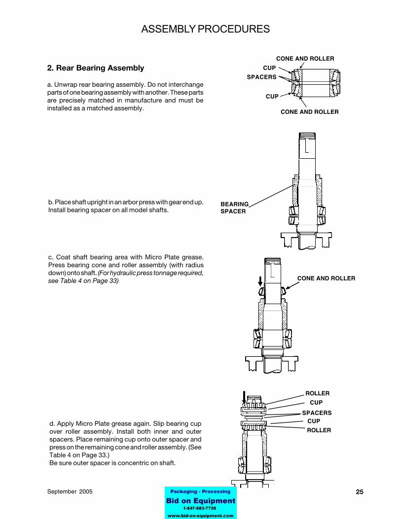
b. Place shaft upright in an arbor press with gear end up.Install bearing spacer on all model shafts.
c. Coat shaft bearing area with Micro Plate grease.Press bearing cone and roller assembly (with radiusdown) onto shaft. (For hydraulic press tonnage required,see Table 4 on Page 33)
2. Rear Bearing Assembly
a. Unwrap rear bearing assembly. Do not interchangeparts of one bearing assembly with another. These partsare precisely matched in manufacture and must beinstalled as a matched assembly.
d. Apply Micro Plate grease again. Slip bearing cupover roller assembly. Install both inner and outerspacers. Place remaining cup onto outer spacer andpress on the remaining cone and roller assembly. (SeeTable 4 on Page 33.)Be sure outer spacer is concentric on shaft.
ROLLER
CUP
SPACERSCUP
ROLLER
BEARINGSPACER
CONE AND ROLLER
ASSEMBLY PROCEDURES
26 95-03069 September 2005
SHIM
ED
BODY
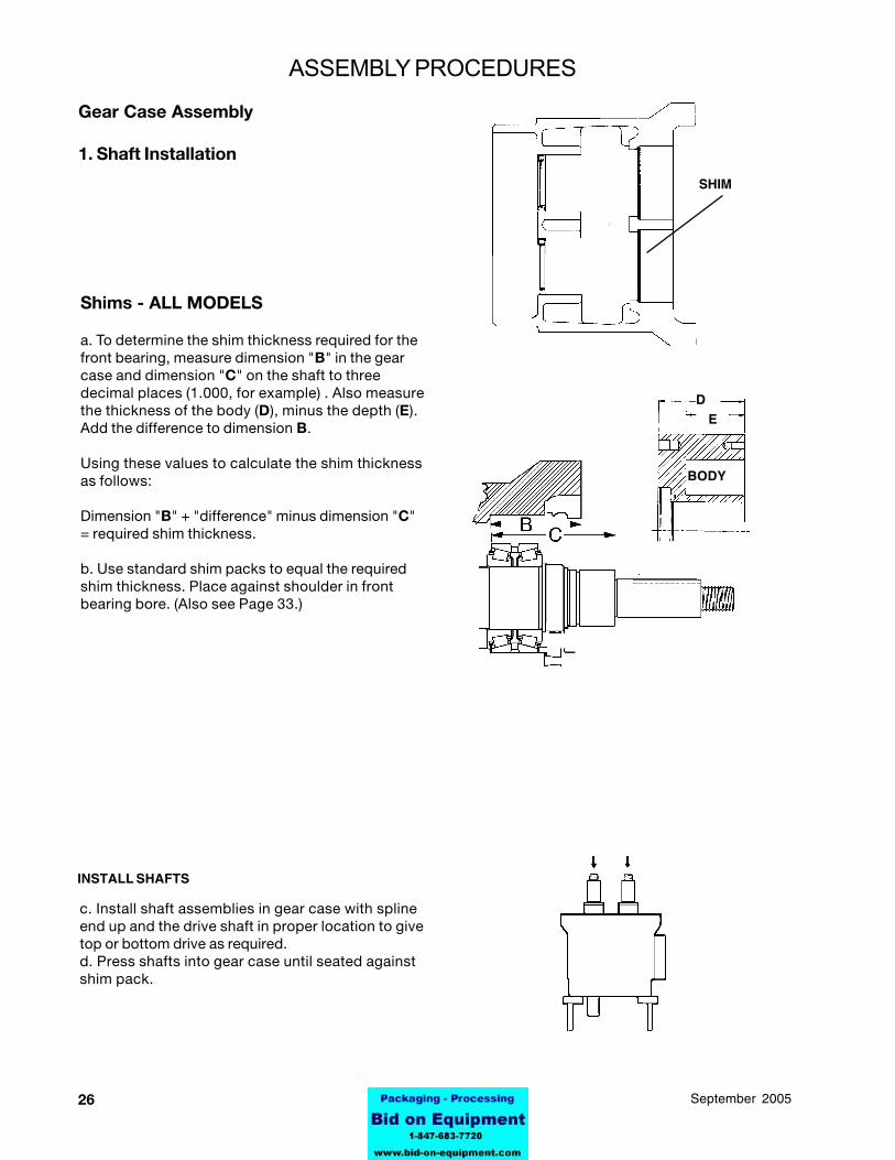
INSTALL SHAFTS
c. Install shaft assemblies in gear case with splineend up and the drive shaft in proper location to givetop or bottom drive as required.d. Press shafts into gear case until seated againstshim pack.
ASSEMBLY PROCEDURES
Shims - ALL MODELS
a. To determine the shim thickness required for thefront bearing, measure dimension "B" in the gearcase and dimension "C" on the shaft to threedecimal places (1.000, for example) . Also measurethe thickness of the body (D), minus the depth (E).Add the difference to dimension B.
Using these values to calculate the shim thicknessas follows:
Dimension "B" + "difference" minus dimension "C"= required shim thickness.
b. Use standard shim packs to equal the requiredshim thickness. Place against shoulder in frontbearing bore. (Also see Page 33.)
Gear Case Assembly
1. Shaft Installation

2795-03069September 2005
i. Install grease seals in bearing retainers (lip in)and coat seal lips with Micro-Plate #555 grease.Coat retainer flanges with silicone sealant.
j.Install bearing retainers.
SHIM HERE IF REQUIRED
2. Rear Seal Assembly
a. Install gear spacers.
b. Coat lip of seals with Micro-Plate grease #555.
c. Press in rear seals with lip facing out.
NOTE: Place plastic bag over shaft end to preventcutting seal when installing.
.
e. Secure shaft assemblies in gear case withbearing retainers. No silicone sealant at this time.
NOTE: Retainer must seat firmly against bearingand leave .010"-.050" clearance with gear case.Use shims between bearing and retainer if required.
f. Check back face clearance. See Table 4 on Page35 and BACK FACE CLEARANCE, page 34.
g. Remove bearing retainers.
h. Grease front and rear bearing through greasefittings until grease is visible around ball assem-blies.
SEAL (LIPFACES OUT)GEAR
SPACER
SEALLIP IN
SILICONESEALANT
FILL WITHMICRO-PLATE #555
BEARING RETAINER
ASSEMBLY PROCEDURES
BEARING RETAINER
FRONT BEARING
.010" - .050"
28 95-03069 September 2005
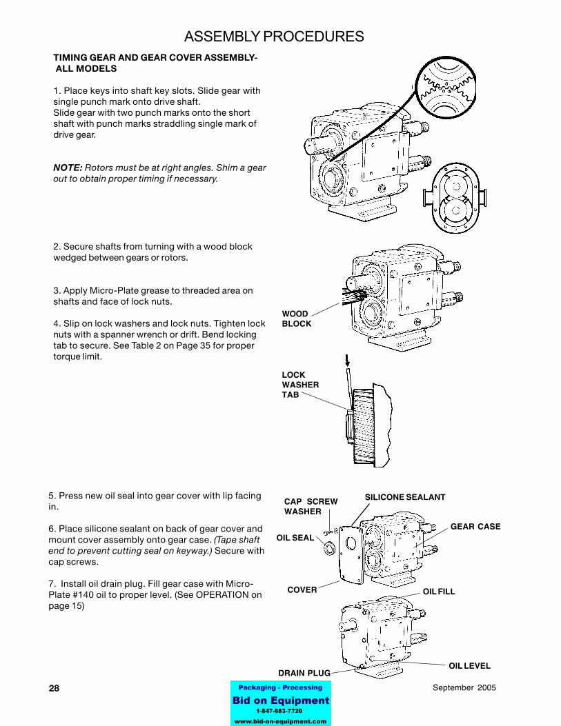
TIMING GEAR AND GEAR COVER ASSEMBLY- ALL MODELS
1. Place keys into shaft key slots. Slide gear withsingle punch mark onto drive shaft.Slide gear with two punch marks onto the shortshaft with punch marks straddling single mark ofdrive gear.
NOTE: Rotors must be at right angles. Shim a gearout to obtain proper timing if necessary.
2. Secure shafts from turning with a wood blockwedged between gears or rotors.
3. Apply Micro-Plate grease to threaded area onshafts and face of lock nuts.
4. Slip on lock washers and lock nuts. Tighten locknuts with a spanner wrench or drift. Bend lockingtab to secure. See Table 2 on Page 35 for propertorque limit.
OIL LEVEL
COVER
WOODBLOCK
OIL SEAL
LOCKWASHERTAB
GEAR CASE
OIL FILL
DRAIN PLUG
ASSEMBLY PROCEDURES
SILICONE SEALANTCAP SCREWWASHER
5. Press new oil seal into gear cover with lip facingin.
6. Place silicone sealant on back of gear cover andmount cover assembly onto gear case. (Tape shaftend to prevent cutting seal on keyway.) Secure withcap screws.
7. Install oil drain plug. Fill gear case with Micro-Plate #140 oil to proper level. (See OPERATION onpage 15)

2995-03069September 2005
A= BACK FACE CLEARANCEB= ROTOR TO BODY CLEARANCEC= FRONT FACE CLEARANCE
ROTOR
PUMPBODY
BODYRETAINERCAP SCREW (2)
EROTORDEPTH
NOTE: Back face clearance for, both rotors must be the same to avoidcrossover interference with rotor hubs.
BODY
F
GEARCASESHOULDER
SHAFTSHOULDER
DTOTAL BODYTHICKNESS
1-17-96
ASSEMBLY PROCEDURESPROPER CLEARANCES1. All Waukesha pumps are designed with close runningclearances and the back face clearance is establishedwith shims during assembly. The shaft is positionedwith shims behind the front bearing and locked into thebearing gear case. The rotors lock against the shaftshoulder and the resultant clearance between body backface and rotor wing is the back face clearance. (SeeTable 1, Page 33, for STANDARD CLEARANCES)
2. To check back face clearance, mount body ontobearing gear case and secure with retaining screws.Assemble rotors and secure with rotor nut assemblies.Measure clearance between body back face and rotorwing with feeler gauges. This can be done by insertingthe feeler gauge in between the rotor wings and bendingthe gauge into position behind the wing or inserting thegauge into a side port and behind the rotor wing.Check readings against recommended STANDARDback face clearance in Table 1, Page 33. Make note ofany corrections required and follow examples to deter-mine exact shim adjustment to make and avoid unnec-essary disassembly and reassembly.
3. To make shim adjustments it is necessary to disas-semble rotors and body and remove shafts. (See Sec-tion Vlll, FLUID HEAD DISASSEMBLY on page 20.)Make required shim adjustment and reassemble. Re-check back face clearances. Be sure both rotors havethe same clearance to avoid crossover interference.
Object: Backface dimension (A) is the differ-ence between the shaft shoulder to the gear-case shoulder (F) and the body thickness (G).(Measure rotor depth (E) and subtract from totalbody thickness (D) to determine (G).
G
30 95-03069 September 2005
INNER SEAL
UNIVERSAL II SEAL COMPONENTS
SEAL SEAT
INNER SEAL
SHAFTO-RING
INNERO-RING
SINGLE MECHANICAL SEAL
INNERWAVE SPRING
O-RING(OUTER)
OUTER SEAL
INNERO-RING
SHAFT O-RING
OUTERWAVE SPRING
DOUBLE MECHANICAL SEAL
SEAL SEAT
INNERWAVE SPRING
STOPPIN

3195-03069September 2005
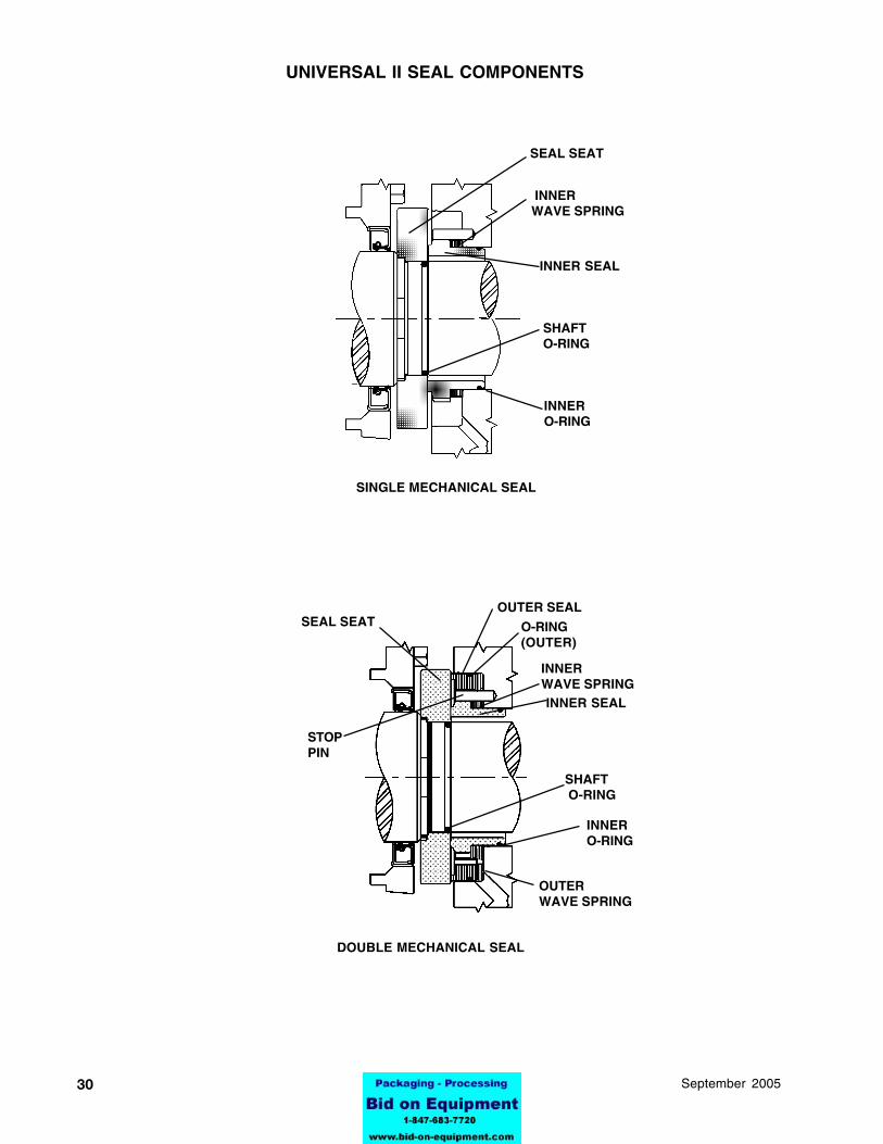
SINGLE AND DOUBLE MECHANICAL SEAL ASSEMBLIES
4. Place inner seal into back of pump body. Be sureto align notches in inner seal with stop pins in thebody. Push evenly and firmly in place,
5. If a double seal is required, install a wave springover inner seal assembly and an outer seal O-ringonto outer seal groove. Place outer seal into pumpbody over inner seal. Be sure to align notches inouter seal with stop pins in body.Perform this procedure on both shafts.
SEAL SEAT
SHAFT O-RING
SHAFT O-RING
SEAL SEAT
OUTER SEAL
O-RING (OUTER)
WAVE SPRING (OUTER)INNER SEAL
WAVE SPRING (INNER)
INNERSEAL
WAVE SPRING (INNER)
O-RING (INNER)
O-RING (INNER)
SHAFTS:1. Place O-ring on shaft.
2. Install seal seat onto shaft. Align drive flats onseat with the drive flats on the shaft. Push seatsquarely against shaft shoulder.BODY:3. Install wave spring on the inner seal and O-ringonto outer groove of inner seat.
Double MechanicalSeal Assembly
Single Mechanical SealAssembly
ASSEMBLY PROCEDURES

32 95-03069 September 2005
Waming: If rotor nuts are not tightened to fhe propertorque, the nuts could loosen during operationcausing severe damage to the pump. Always use atorque wrench!
INSTALL COVER5. Install cleaned cover O-ring into groove in coverand install cover onto pump. Tighten cover securelyusing cover nuts.NOTE: Apply a food grade anti-seize compund toshaft and body studs prior to assembly of rotors andcover.
IMPORTANT! If a double seal arrangement is used,the seals must be provided with a clean, compatiblebarrier fluid. Make certain that flush ports in pumpbody are clean and clear.
INSTALL BODY1. Install the body to pump gear case assembly. Usecare to avoid damaging seals as the body is drawnover the shafts. Use two (2) socket head cap screwsto secure the body to the gear case.
INSTALL ROTORS2. Install new rotor hub O-rings onto groove in rotors.Install rotors onto shafts.Lubricate all O-rings with a lubrication compound thatis compatible with O-ring material and process fluid/s.
INSTALL ROTOR NUT ASSEMBLIES3. Install Belleville washer into rotor nut with cone ofwasher "pointing" toward the nut. Place retainerO-ring into rotor nut to retain washer.
4. Install new rotor nut O-ring onto rotor nut.Screw rotor nuts onto shafts (clockwise) and tighten torequired torque.
See Table on page 33 for wrench sizeand torque values)
ASSEMBLY PROCEDURES
COVER O-RINGCOVER
BODY
ROTOR (2)
SOCKET HEAD CAP SCREW (2)
COVER NUT (8)
NEW ROTOR NUT O-RING (2)
NEW ROTOR HUBO-RING (2)
O-RING (2)
WASHER (2)
ROTOR NUT (2)
3395-03069September 2005
SERIES STANDARD REPLACEMENT
MODEL SHAFT SHAFT
006U2
015U2 0.113" 0.110"
018U2
030U2 0.105" 0.102"
045U2
060U2
130U2 0.093" 0.088"
180U2
220U2 0.115" 0.110"
320U2 0.125" 0.120"
TABLE 4. ARBOR OR HYDRAULIC PRESS REQ'D - TONS
FRONT REAR BEARINGSERIES SHAFT BEARING SHAFTMODEL IN OUT ON OFF ON OFF
006U2
015U2 0.25 0.5 0.5 1 0.5 1
018U2
030U2 0.25 1 0.5 1 0.5 1
045U2060U2 0.5 1 2 5 3 5130U2180U2
220U2 0.5 1 5 15 5 15
320U2 0.5 1 5 20 5 20
SECTION XREFERENCE TABLES AND REPAIR PARTS LIST
8-28-98
TABLE 3. SUGGESTED SHIMS - INCHES
0.002" 0.002" 0.005"
0.002" 0.002" 0.005"
0.004" 0.005" 0.008"
0.005" 0.006" 0.008"
0.005" 0.010" 0.011"
TABLE 1. STANDARD ROTOR CLEARANCES*- INCHES
006U2015U2018U2030U2045U2060U2130U2180U2220U2320U2
A B C BACK ROTOR FRONT
MODEL FACE TO BODY FACE
*For non-standard rotor clearance, contact ApplicationEngineering at Waukesha Cherry-Burrell
TABLE 2. TORQUE VALUES-FT-LBS
LOCK NUTS MODEL GEAR ROTOR
006U2 75 50
015U2 75 50
018U2 75 50
030U2 100 120
045U2 140 250
060U2 140 250
130U2 140 250
180U2 230 325
220U2 230 325
320U2 320 375
EARLY BODY 8/98ROTOR COVER RETAINER COVER
MODEL NUT NUT BOLT NUT006U2015U2 15/16" 7/16" 3/16" 5/8"018U2030U2 1-1/4" 1/2" 3/16" 5/8"045U2060U2 1-5/8" 9/16" 1/4" 1"130U2180U2220U2 2-1/4" 5/8" 5/16" 1"320U2 2-3/8" 1" 5/16" 1"
UNIVERSAL II SERIES WRENCH SIZES - INCHES
NOTE: Applications over 200 PSI when used with the 8/98cover nuts will require the 8/98 studs.
34 95-03069 September 2005
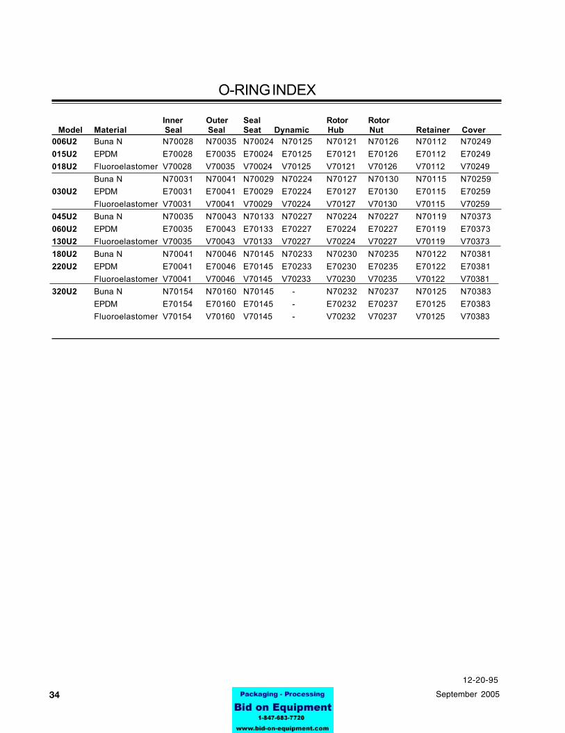
O-RING INDEX
Inner Outer Seal Rotor Rotor Model Material Seal Seal Seat Dynamic Hub Nut Retainer Cover006U2 Buna N N70028 N70035 N70024 N70125 N70121 N70126 N70112 N70249015U2 EPDM E70028 E70035 E70024 E70125 E70121 E70126 E70112 E70249018U2 Fluoroelastomer V70028 V70035 V70024 V70125 V70121 V70126 V70112 V70249
Buna N N70031 N70041 N70029 N70224 N70127 N70130 N70115 N70259030U2 EPDM E70031 E70041 E70029 E70224 E70127 E70130 E70115 E70259
Fluoroelastomer V70031 V70041 V70029 V70224 V70127 V70130 V70115 V70259045U2 Buna N N70035 N70043 N70133 N70227 N70224 N70227 N70119 N70373060U2 EPDM E70035 E70043 E70133 E70227 E70224 E70227 E70119 E70373130U2 Fluoroelastomer V70035 V70043 V70133 V70227 V70224 V70227 V70119 V70373180U2 Buna N N70041 N70046 N70145 N70233 N70230 N70235 N70122 N70381220U2 EPDM E70041 E70046 E70145 E70233 E70230 E70235 E70122 E70381
Fluoroelastomer V70041 V70046 V70145 V70233 V70230 V70235 V70122 V70381320U2 Buna N N70154 N70160 N70145 - N70232 N70237 N70125 N70383
EPDM E70154 E70160 E70145 - E70232 E70237 E70125 E70383Fluoroelastomer V70154 V70160 V70145 - V70232 V70237 V70125 V70383
12-20-95
3595-03069September 2005
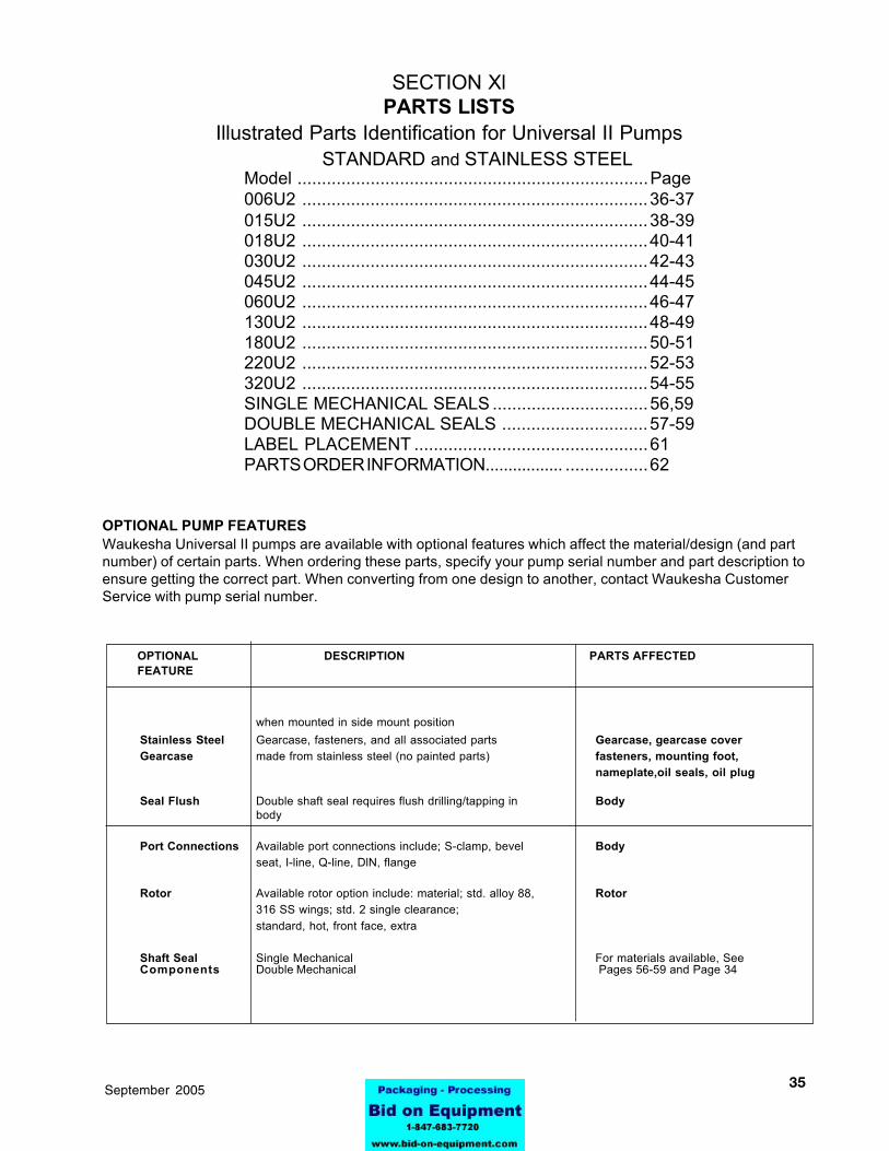
when mounted in side mount positionStainless Steel Gearcase, fasteners, and all associated parts Gearcase, gearcase coverGearcase made from stainless steel (no painted parts) fasteners, mounting foot,
nameplate,oil seals, oil plug
Seal Flush Double shaft seal requires flush drilling/tapping in Bodybody
Port Connections Available port connections include; S-clamp, bevel Bodyseat, I-line, Q-line, DlN, flange
Rotor Available rotor option include: material; std. alloy 88, Rotor316 SS wings; std. 2 single clearance;standard, hot, front face, extra
Shaft Seal Single Mechanical For materials available, SeeComponents Double Mechanical Pages 56-59 and Page 34
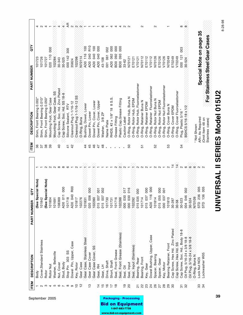
SECTION XlPARTS LISTS
Illustrated Parts Identification for Universal II PumpsSTANDARD and STAINLESS STEEL
Model ........................................................................Page006U2 .......................................................................36-37015U2 .......................................................................38-39018U2 .......................................................................40-41030U2 .......................................................................42-43045U2 .......................................................................44-45060U2 .......................................................................46-47130U2 .......................................................................48-49180U2 .......................................................................50-51220U2 .......................................................................52-53320U2 .......................................................................54-55SINGLE MECHANICAL SEALS ................................56,59DOUBLE MECHANICAL SEALS ..............................57-59LABEL PLACEMENT ................................................61PARTS ORDER INFORMATION................. .................62
OPTIONAL PUMP FEATURESWaukesha Universal II pumps are available with optional features which affect the material/design (and partnumber) of certain parts. When ordering these parts, specify your pump serial number and part description toensure getting the correct part. When converting from one design to another, contact Waukesha CustomerService with pump serial number.
OPTIONAL DESCRIPTION PARTS AFFECTEDFEATURE
36 95-03069 September 2005
45
46
50
2
28
20
30
48
7
24
21
26
36
37
38
22
2
3
16
10
29
30
1
8
53
6
44
2
7
41 13
33
34
15
39
40
8
9
1
41
23
17
14
1
9
12
54
47
31 3
5
1 5
52
4
UN
IVE
RS
AL
II S
ER
IES
Mo
del
006
U2
DO
UB
LE
ME
CH
AN
ICA
L S
EA
L(S
ee
pa
ge
s 58
to
59)
32
42

3795-03069September 2005
123123123123123123123123123123123123123123123123123123123123123123123123123123123123123123123123123123123123123123123123123123123123123123123123123123123123123123123123123
123123123123123123123123123123123123123123123123123123123123123123123123123123123123123123123123123123123123123123123123123123123123123123123123123123123123123123123123123123123
123123123123123123123123123123123123123123123123123123123123123123123123123123123123123123123123123123123123123123123123123123123123123123123123123123123123123123123123123123123
1234512345123451234512345123451234512345123451234512345123451234512345123451234512345123451234512345123451234512345123451234512345123451234512345123451234512345123451234512345123451234512345123451234512345123451234512345123451234512345123451234512345123451234512345123451234512345123451234512345
123123123123123123123123123123123123123123123123123123123123123123123123123123123123123123123123123123123123123123123123123123123123123123123123123123123123123123123123123
123123123123123123123123123123123123123123123123123123123123123123123123123123123123123123123123123123123123123123123123123123123123123123123123123123123123123123123123123
123123123123123123123123123123123123123123123123123123123123123123123123123123123123123123123123123123123123123123123123123123123123123123123123123123123123123123123123123
123123123123123123123123123123123123123123123123123123123123123123123123123123123123123123123123123123123123123123123123123123123123123123123123123123123123123123123123123123
12345123451234512345123451234512345123451234512345123451234512345123451234512345123451234512345123451234512345123451234512345123451234512345123451234512345123451234512345123451234512345123451234512345123451234512345123451234512345123451234512345123451234512345123451234512345123451234512345
123123123123123123123123123123123123123123123123123123123123123123123123123123123123123123123123123123123123123123123123123123123123123123123123123123123123123123123123123123
12345123451234512345123451234512345123451234512345123451234512345123451234512345123451234512345123451234512345123451234512345123451234512345123451234512345123451234512345123451234512345
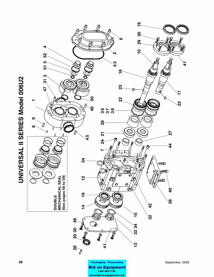
1
Bod
y(S
ee
Sp
ec
ial
No
te)
1
2C
ove
r,S
tand
ard
Sta
inle
ss10
1842
1 3
Ro
tor
(Se
e S
pe
cia
l N
ote
)2
4
Ro
tor
Nut
1018
042
5W
ashe
r, B
elle
ville
1016
912
6N
ut,
Co
ver
1083
698
7
Stu
d, B
od
yA
D0
011
00
08
8S
top
Pin
3
03
SS
1017
186
9
Do
wel
P
in,
Up
per
, C
ase
AD
0 0
40
R00
1 1
0K
ey,
Ro
tor
1018
172
12G
ear
Cas
e10
2276
1G
ear
Cas
e, S
tain
less
Ste
el10
1831
1 1
3G
ear
Cas
e C
ove
r02
0 0
06
000
1G
ear
Cas
e C
ove
r, S
S10
2280
1 1
4G
ear,
RH
015
007
00
11
15
Gea
r, L
H01
5 0
07
002
1 1
6D
rive
, S
haft
1017
301
17
Sho
rt,
Sha
ft10
1731
1 1
8S
eal,
Fro
nt G
reas
e10
1716
2S
eal,
Fro
nt G
reas
e (S
tain
less
)10
2288
2 1
9S
eal,
Oil
000
030
01
72
20
Sea
l, In
put
000
030
01
61
Sea
l, In
put
(S
tain
less
)10
2292
1 2
1B
eari
ng,
Rea
r01
5 03
5 0
002
22
Bea
ring
, F
ront
1017
142
23
Key
, G
ear
015
037
00
02
24
Do
wel
Bus
hing
, U
pp
er,
Cas
eA
D0
116
00
01
26
Sp
acer
, B
eari
ng10
1814
2 2
7S
pac
er,
Gea
r01
5 0
55
000
2 2
8K
ey, M
oto
r00
0 0
37
001
1 2
9B
eari
ng R
etai
ner,
Fro
nt10
1810
2 3
0C
ap S
crew
, H
ex H
d.
Zin
c P
late
d30
-287
14
Cap
Scr
ew,
Hex
Hd
. S
S30
-58
14
31
Cap
Scr
ew,
So
c. H
d.,
Bo
dy
18-8
30-5
232
32
Oil
Plu
g,
5/16
-24
x 3/
8 18
-800
4 0
46
002
6O
il P
lug
, 5/
16-2
4 x
3/8
18-8
30-5
246
O-R
ing
, B
una
NN
7010
96
33
Lock
Nut
NO
5S
TD
23
6 0
052
34
Lock
was
her
W05
ST
D
136
005
2
36S
him
, F
ront
Bea
ring
0.0
02"
1017
234
37S
him
, F
ront
Bea
ring
0.0
10"
1017
262
38S
him
, F
ront
Bea
ring
0.0
50"
1017
274
39M
oun
ting
Fo
ot,
Gea
r C
ase
020
110
00
01
Mo
unti
ng F
oo
t, G
ear
Cas
e, S
S10
2284
140
Cap
Scr
ew,
So
c. H
d.
Zin
c P
late
d30
-343
4C
ap S
crew
, S
oc.
Hd
. S
S 1
8-8
30-5
254
41S
ilico
ne S
eala
nt,
RT
V00
0 14
2 3
00A
R42
Cle
ano
ut P
lug
1-1
/16-
1235
824
2C
lean
out
Plu
g 1
-1/1
6-12
SS
1022
982
O-R
ing
, B
una
N70
114
244
Bus
hing
, D
ow
el,
Low
erA
D0
116
10
01
45D
ow
el P
in,
Low
erA
D0
040
R
101
46D
ow
el P
in,
Co
ver,
Lo
wer
AD
0 0
40
100
147
Do
wel
Pin
, C
ove
r, U
pp
erA
D0
040
00
01
48W
ashe
r,
3/8
ZP
43-1
086
*N
ame
Pla
te00
1 0
61
002
1*
RH
DS
, #2
x 1
/8"
18
8 S
.S.
AD
0 0
62
000
4*
Gre
ase
Fit
ting
BD
0 0
92
000
4*
Pla
stic
Cap
,Gre
ase
Fit
ting
BD
0 0
93
000
4*
Cau
tio
n La
bel
33-6
22
50O
-Rin
g,
Ro
tor
Hub
, B
una
NN
7012
12
O-R
ing
, R
oto
r H
ub,
EP
DM
E7
01
21
O-R
ing
, R
oto
r H
ub,
Flu
oro
elas
tom
erV
70
12
151
O-R
ing
, R
etai
ner
Bun
a N
N70
112
2O
-Rin
g,
Ret
aine
r E
PD
ME
70
11
2O
-Rin
g,
Ret
aine
r F
luo
roel
asto
mer
V7
01
12
52O
-Rin
g,
Ro
tor
Nut
Bun
a N
N70
126
2O
-Rin
g,
Ro
tor
Nut
EP
DM
E7
01
26
O-R
ing
, R
oto
r N
ut F
luo
roel
asto
mer
V7
01
26
53O
-Rin
g,
Co
ver
Bun
a N
N70
249
1O
-Rin
g,
Co
ver
EP
DM
E7
02
49
O-R
ing
, C
ove
r F
luo
roel
asto
mer
V7
02
49
54P
lug
, P
last
ic 5
/16
"00
0 1
21
003
8B
SH
CS
5/1
6-18
x 1
/230
-524
8
For S
tain
less
Ste
el G
ear C
ases
ITE
M
D
ES
CR
IPT
ION
PA
RT
NU
MB
ER
QT
YIT
EM
D
ES
CR
IPT
ION
PA
RT
NU
MB
ER
QT
Y
Sp
ecia
l No
te o
n p
age
35
UN
IVE
RS
AL
II S
ER
IES
Mo
del
006
U2
* N
ot
Sho
wn
AR
= A
s R
equi
red
(Om
it I
tem
48
on
Sta
inle
ss c
ases
)
8-2
8-9
8

38 95-03069 September 2005
46
50
45
2
28
20
30
48
7
24
21
263
63
73
8
22
2
3
1
6
10
29
30
1
8
53
6
44
2
7
41 13
33
34
15
32
42
39
40
8
9
1
41
23
17
47
31 3
5
1 5
52
4
UN
IVE
RS
AL
II S
ER
IES
Mo
del
015
U2
DO
UB
LE
ME
CH
AN
ICA
L S
EA
L(S
ee
pa
ge
s 56
to
59)
14
1
9
12
5
4
3995-03069September 2005
123123123123123123123123123123123123123123123123123123123123123123123123123123123123123123123123123123123123123123123123123123123123123123123123123123123123123123123123123
123123123123123123123123123123123123123123123123123123123123123123123123123123123123123123123123123123123123123123123123123123123123123123123123123123123123123123123123123123123
123123123123123123123123123123123123123123123123123123123123123123123123123123123123123123123123123123123123123123123123123123123123123123123123123123123123123123123123123123123
1234512345123451234512345123451234512345123451234512345123451234512345123451234512345123451234512345123451234512345123451234512345123451234512345123451234512345123451234512345123451234512345123451234512345123451234512345123451234512345123451234512345123451234512345123451234512345123451234512345
123123123123123123123123123123123123123123123123123123123123123123123123123123123123123123123123123123123123123123123123123123123123123123123123123123123123123123123123123
123123123123123123123123123123123123123123123123123123123123123123123123123123123123123123123123123123123123123123123123123123123123123123123123123123123123123123123123123
123123123123123123123123123123123123123123123123123123123123123123123123123123123123123123123123123123123123123123123123123123123123123123123123123123123123123123123123123
123123123123123123123123123123123123123123123123123123123123123123123123123123123123123123123123123123123123123123123123123123123123123123123123123123123123123123123123123
123451234512345123451234512345123451234512345123451234512345123451234512345123451234512345123451234512345123451234512345123451234512345123451234512345123451234512345123451234512345123451234512345123451234512345123451234512345123451234512345123451234512345123451234512345123451234512345
123123123123123123123123123123123123123123123123123123123123123123123123123123123123123123123123123123123123123123123123123123123123123123123123123123123123123123123123123123123
123451234512345123451234512345123451234512345123451234512345123451234512345123451234512345123451234512345123451234512345123451234512345123451234512345123451234512345123451234512345123451234512345123451234512345
1
Bod
y(S
ee
Sp
ec
ial
No
te)
1
2C
ove
r,S
tand
ard
Sta
inle
ss10
1842
1 3
Ro
tor
(Se
e S
pe
cia
l N
ote
)2
4
Ro
tor
Nut
1018
042
5W
ashe
r, B
elle
ville
1016
912
6N
ut,
Co
ver
1083
698
7
Stu
d, B
od
yA
D0
011
00
08
8S
top
Pin
3
03
SS
1017
186
9
Do
wel
P
in,
Up
per
, C
ase
AD
0 0
40
R00
1 1
0K
ey,
Ro
tor
1018
172
12G
ear
Cas
e10
2276
1G
ear
Cas
e, S
tain
less
Ste
el10
1831
1 1
3G
ear
Cas
e C
ove
r02
0 0
06
000
1G
ear
Cas
e C
ove
r, S
S10
2280
1 1
4G
ear,
RH
015
007
00
11
15
Gea
r, L
H01
5 0
07
002
1 1
6D
rive
, S
haft
1017
301
17
Sho
rt,
Sha
ft10
1731
1 1
8S
eal,
Fro
nt G
reas
e10
1716
2S
eal,
Fro
nt G
reas
e (S
tain
less
)10
2288
2 1
9S
eal,
Oil
000
030
01
72
20
Sea
l, In
put
000
030
01
61
Sea
l, In
put
(S
tain
less
)10
2292
1 2
1B
eari
ng,
Rea
r01
5 03
5 0
002
22
Bea
ring
, F
ront
1017
142
23
Key
, G
ear
015
037
00
02
24
Do
wel
Bus
hing
, U
pp
er,
Cas
eA
D0
116
00
01
26
Sp
acer
, B
eari
ng10
1814
2 2
7S
pac
er,
Gea
r01
5 0
55
000
2 2
8K
ey, M
oto
r00
0 0
37
001
1 2
9B
eari
ng R
etai
ner,
Fro
nt10
1810
2 3
0C
ap S
crew
, H
ex H
d.
Zin
c P
late
d30
-287
14
Cap
Scr
ew,
Hex
Hd
. S
S30
-58
14
31
Cap
Scr
ew,
So
c. H
d.,
Bo
dy
18-8
30-5
232
32
Oil
Plu
g,
5/16
-24
x 3/
8 18
-800
4 0
46
002
6O
il P
lug
, 5/
16-2
4 x
3/8
18-8
30-5
246
O-R
ing
, B
una
NN
7010
96
33
Lock
Nut
NO
5S
TD
23
6 0
052
34
Lock
was
her
W05
ST
D
136
005
2
36S
him
, F
ront
Bea
ring
0.0
02"
1017
234
37S
him
, F
ront
Bea
ring
0.0
10"
1017
262
38S
him
, F
ront
Bea
ring
0.0
50"
1017
274
39M
oun
ting
Fo
ot,
Gea
r C
ase
020
110
00
01
Mo
unti
ng F
oo
t, G
ear
Cas
e, S
S10
2284
140
Cap
Scr
ew,
So
c. H
d.
Zin
c P
late
d30
-343
4C
ap S
crew
, S
oc.
Hd
. S
S 1
8-8
30-5
254
41S
ilico
ne S
eala
nt,
RT
V00
0 14
2 3
00A
R42
Cle
ano
ut P
lug
1-1
/16-
1235
824
2C
lean
out
Plu
g 1
-1/1
6-12
SS
1022
982
O-R
ing
, B
una
N70
114
244
Bus
hing
, D
ow
el,
Low
erA
D0
116
10
01
45D
ow
el P
in,
Low
erA
D0
040
R
101
46D
ow
el P
in,
Co
ver,
Lo
wer
AD
0 0
40
100
147
Do
wel
Pin
, C
ove
r, U
pp
erA
D0
040
00
01
48W
ashe
r,
3/8
ZP
43-1
086
*N
ame
Pla
te00
1 0
61
002
1*
RH
DS
, #2
x 1
/8"
18
8 S
.S.
AD
0 0
62
000
4*
Gre
ase
Fit
ting
BD
0 0
92
000
4*
Pla
stic
Cap
,Gre
ase
Fit
ting
BD
0 0
93
000
4*
Cau
tio
n La
bel
33-6
22
50O
-Rin
g,
Ro
tor
Hub
, B
una
NN
7012
12
O-R
ing
, R
oto
r H
ub,
EP
DM
E7
01
21
O-R
ing
, R
oto
r H
ub,
Flu
oro
elas
tom
erV
70
12
151
O-R
ing
, R
etai
ner
Bun
a N
N70
112
2O
-Rin
g,
Ret
aine
r E
PD
ME
70
11
2O
-Rin
g,
Ret
aine
r F
luo
roel
asto
mer
V7
01
12
52O
-Rin
g,
Ro
tor
Nut
Bun
a N
N70
126
2O
-Rin
g,
Ro
tor
Nut
EP
DM
E7
01
26
O-R
ing
, R
oto
r N
ut F
luo
roel
asto
mer
V7
01
26
53O
-Rin
g,
Co
ver
Bun
a N
N70
249
1O
-Rin
g,
Co
ver
EP
DM
E7
02
49
O-R
ing
, C
ove
r F
luo
roel
asto
mer
V7
02
49
54P
lug
, P
last
ic 5
/16
"00
0 1
21
003
8B
SH
CS
5/1
6-18
x 1
/230
-524
8
For S
tain
less
Ste
el G
ear C
ases
UN
IVE
RS
AL
II S
ER
IES
Mo
del
015
U2
ITE
M
DE
SC
RIP
TIO
N
PA
RT
NU
MB
ER
QT
YIT
EM
D
ES
CR
IPT
ION
P
AR
T N
UM
BE
R
QT
Y
* N
ot
Sho
wn
AR
= A
s R
equi
red
(Om
it I
tem
48
on
Sta
inle
ss c
ases
)
Sp
ecia
l No
te o
n p
age
35
8-28
-98

40 95-03069 September 2005
45
2
28
20
30
48
7
24
21
263
63
73
8
22
2
3
1
6
10
29
3
0
18
53
6
44
2
7
41 13
33
34
15
32
42
39
40
8
9
1
41
23
17
47
31 3
5
1 5
52
4
UN
IVE
RS
AL
II S
ER
IES
Mo
del
018
U2
DO
UB
LE
ME
CH
AN
ICA
L S
EA
L(S
ee
pa
ge
s 56
to
59)
14
1
9
12
5
4
46
50

4195-03069September 2005
123123123123123123123123123123123123123123123123123123123123123123123123123123123123123123123123123123123123123123123123123123123123123123123123123123123123123123123123123
123123123123123123123123123123123123123123123123123123123123123123123123123123123123123123123123123123123123123123123123123123123123123123123123123123123123123123123123123
123123123123123123123123123123123123123123123123123123123123123123123123123123123123123123123123123123123123123123123123123123123123123123123123123123123123123123123123123
123412341234123412341234123412341234123412341234123412341234123412341234123412341234123412341234123412341234123412341234123412341234123412341234123412341234123412341234123412341234123412341234123412341234123412341234123412341234
123123123123123123123123123123123123123123123123123123123123123123123123123123123123123123123123123123123123123123123123123123123123123123123123123123123123123123123123123
123456123456123456123456123456123456123456123456123456123456123456123456123456123456123456123456123456123456123456123456123456123456123456123456123456123456123456123456123456123456123456123456123456123456123456123456123456123456123456123456123456123456123456123456123456123456123456123456123456123456123456123456123456123456123456123456123456
123123123123123123123123123123123123123123123123123123123123123123123123123123123123123123123123123123123123123123123123123123123123123123123123123123123123123123123123123123123
123123123123123123123123123123123123123123123123123123123123123123123123123123123123123123123123123123123123123123123123123123123123123123123123123123123123123123123123123123123
123456123456123456123456123456123456123456123456123456123456123456123456123456123456123456123456123456123456123456123456123456123456123456123456123456123456123456123456123456123456123456123456123456123456123456123456123456123456123456123456123456123456123456123456123456123456123456123456123456123456123456123456123456123456123456123456123456123456123456
123123123123123123123123123123123123123123123123123123123123123123123123123123123123123123123123123123123123123123123123123123123123123123123123123123123123123123123123123123123
12345123451234512345123451234512345123451234512345123451234512345123451234512345123451234512345123451234512345123451234512345123451234512345123451234512345123451234512345123451234512345
1
Bod
y(S
ee
Sp
ec
ial
No
te)
1
2C
ove
r,S
tand
ard
Sta
inle
ss10
1842
1 3
Ro
tor
(Se
e S
pe
cia
l N
ote
)2
4
Ro
tor
Nut
1018
042
5W
ashe
r, B
elle
ville
1016
912
6N
ut,
Co
ver
1083
698
7
Stu
d, B
od
y10
1721
8 8
Sto
p P
in
303
S
S10
1718
6
9D
ow
el
Pin
, U
pp
er,
Cas
eA
D0
040
R
001
10
Key
, R
oto
r10
1819
212
Gea
r C
ase
1022
761
Gea
r C
ase,
Sta
inle
ss S
teel
1018
311
13
Gea
r C
ase
Co
ver
020
006
00
01
Gea
r C
ase
Co
ver,
SS
1022
801
14
Gea
r, R
H01
5 0
07
001
1 1
5G
ear,
LH
015
007
00
21
16
Dri
ve,
Sha
ft10
1742
1 1
7S
hort
, S
haft
1017
431
18
Sea
l, F
ront
Gre
ase
1017
162
Sea
l, F
ront
Gre
ase
(Sta
inle
ss)
1022
882
19
Sea
l, O
il00
0 0
30
017
2 2
0S
eal,
Inp
ut00
0 0
30
016
1S
eal,
Inp
ut (
Sta
inle
ss)
1022
921
21
Bea
ring
, R
ear
015
035
000
2 2
2B
eari
ng,
Fro
nt10
1714
2 2
3K
ey,
Gea
r01
5 0
37
000
2 2
4D
ow
el B
ushi
ng,
Up
per
, C
ase
AD
0 1
16
000
1 2
6S
pac
er,
Bea
ring
1018
142
27
Sp
acer
, G
ear
015
055
00
02
28
Key
, Mo
tor
000
037
00
11
29
Bea
ring
Ret
aine
r, F
ront
1018
102
30
Cap
Scr
ew,
Hex
Hd
. Z
inc
Pla
ted
30-2
871
4C
ap S
crew
, H
ex H
d.
SS
30-5
81
4 3
1C
ap S
crew
, S
oc.
Hd
., B
od
y 18
-830
-211
2 3
2O
il P
lug
, 5/
16-2
4 x
3/8
18-8
004
046
00
26
Oil
Plu
g,
5/16
-24
x 3/
8 18
-830
-524
6O
-Rin
g,
Bun
a N
N70
109
6 3
3Lo
ck N
ut N
O5
ST
D
236
005
2 3
4Lo
ckw
ashe
r W
05S
TD
13
6 0
052
36S
him
, F
ront
Bea
ring
0.0
02"
1017
234
37S
him
, F
ront
Bea
ring
0.0
10"
1017
262
38S
him
, F
ront
Bea
ring
0.0
50"
1017
274
39M
oun
ting
Fo
ot,
Gea
r C
ase
020
110
00
01
Mo
unti
ng F
oo
t, G
ear
Cas
e, S
S10
2284
140
Cap
Scr
ew,
So
c. H
d.
Zin
c P
late
d30
-343
4C
ap S
crew
, S
oc.
Hd
. S
S 1
8-8
30-5
254
41S
ilico
ne S
eala
nt,
RT
V00
0 14
2 3
00A
R42
Cle
ano
ut P
lug
1-1
/16-
1235
824
2C
lean
out
Plu
g 1
-1/1
6-12
SS
1022
982
O-R
ing
, B
una
N70
114
244
Bus
hing
, D
ow
el,
Low
erA
D0
116
10
01
45D
ow
el P
in,
Low
erA
D0
040
R
101
46D
ow
el P
in,
Co
ver,
Lo
wer
AD
0 0
40
100
147
Do
wel
Pin
, C
ove
r, U
pp
erA
D0
040
00
01
48W
ashe
r,
3/8
ZP
43-1
086
*N
ame
Pla
te00
1 0
61
002
1*
RH
DS
, #2
x 1
/8"
18
8 S
.S.
AD
0 0
62
000
4*
Gre
ase
Fit
ting
BD
0 0
92
000
4*
Pla
stic
Cap
,Gre
ase
Fit
ting
BD
0 0
93
000
4*
Cau
tio
n La
bel
33-6
22
50O
-Rin
g,
Ro
tor
Hub
, B
una
NN
7012
12
O-R
ing
, R
oto
r H
ub,
EP
DM
E7
01
21
O-R
ing
, R
oto
r H
ub,
Flu
oro
elas
tom
erV
70
12
151
O-R
ing
, R
etai
ner
Bun
a N
N70
112
2O
-Rin
g,
Ret
aine
r E
PD
ME
70
11
2O
-Rin
g,
Ret
aine
r F
luo
roel
asto
mer
V7
01
12
52O
-Rin
g,
Ro
tor
Nut
Bun
a N
N70
126
2O
-Rin
g,
Ro
tor
Nut
EP
DM
E7
01
26
O-R
ing
, R
oto
r N
ut F
luo
roel
asto
mer
V7
01
26
53O
-Rin
g,
Co
ver
Bun
a N
N70
249
1O
-Rin
g,
Co
ver
EP
DM
E7
02
49
O-R
ing
, C
ove
r F
luo
roel
asto
mer
V7
02
49
54P
lug
, P
last
ic 5
/16
"00
0 1
21
003
8B
SH
CS
5/1
6-18
x 1
/230
-524
8
For S
tain
less
Ste
el G
ear C
ases
UN
IVE
RS
AL
II S
ER
IES
Mo
del
018
U2
Sp
ecia
l No
te o
n p
age
35
* N
ot
Sho
wn
AR
= A
s(O
mit
Ite
m 4
8 o
nS
tain
less
cas
es)
ITE
M D
ES
CR
IPT
ION
P
AR
T N
UM
BE
R
QT
YIT
EM
D
ES
CR
IPT
ION
P
AR
T N
UM
BE
R
Q
TY
8-28
-98
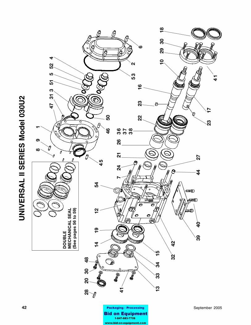
42 95-03069 September 2005
45
2
28
20
30
48
7
24
21
263
63
73
8
22
2
3
1
6
10
29
30
1
8
53
6
44
2
7
41 13
33
34
15
32
42
39
40
8
9
1
41
23
17
47
31 3
51
5
52
4
UN
IVE
RS
AL
II S
ER
IES
Mo
del
030
U2
DO
UB
LE
ME
CH
AN
ICA
L S
EA
L(S
ee
pa
ge
s 56
to
59)
14
1
9
12
5
4
46
50

4395-03069September 2005
123123123123123123123123123123123123123123123123123123123123123123123123123123123123123123123123123123123123123123123123123123123123123123123123123123123123123123123123123123
123456123456123456123456123456123456123456123456123456123456123456123456123456123456123456123456123456123456123456123456123456123456123456123456123456123456123456123456123456123456123456123456123456123456123456123456123456123456123456123456123456123456123456123456123456123456123456123456123456123456123456123456123456123456123456123456123456123456123456
123123123123123123123123123123123123123123123123123123123123123123123123123123123123123123123123123123123123123123123123123123123123123123123123123123123123123123123123123123123
123123123123123123123123123123123123123123123123123123123123123123123123123123123123123123123123123123123123123123123123123123123123123123123123123123123123123123123123123123
123123123123123123123123123123123123123123123123123123123123123123123123123123123123123123123123123123123123123123123123123123123123123123123123123123123123123123123123123123123
123123123123123123123123123123123123123123123123123123123123123123123123123123123123123123123123123123123123123123123123123123123123123123123123123123123123123123123123123123123
123123123123123123123123123123123123123123123123123123123123123123123123123123123123123123123123123123123123123123123123123123123123123123123123123123123123123123123123123123123
123123123123123123123123123123123123123123123123123123123123123123123123123123123123123123123123123123123123123123123123123123123123123123123123123123123123123123123123123123123
123123123123123123123123123123123123123123123123123123123123123123123123123123123123123123123123123123123123123123123123123123123123123123123123123123123123123123123123123123123
1234512345123451234512345123451234512345123451234512345123451234512345123451234512345123451234512345123451234512345123451234512345123451234512345123451234512345123451234512345123451234512345123451234512345123451234512345123451234512345123451234512345123451234512345123451234512345123451234512345
12345123451234512345123451234512345123451234512345123451234512345123451234512345123451234512345123451234512345123451234512345123451234512345123451234512345123451234512345123451234512345123451234512345
123123123123123123123123123123123123123123123123123123123123123123123123123123123123123123123123123123123123123123123123123123123123123123123123123123123123123123123123123
1
Bod
y(S
ee
Sp
ec
ial
No
te)
1
2C
ove
r,S
tand
ard
Sta
inle
ss10
1845
1 3
Ro
tor
(Se
e S
pe
cia
l N
ote
)2
4
Ro
tor
Nut
1018
052
5W
ashe
r, B
elle
ville
1016
922
6N
ut,
Co
ver
1083
698
7
Stu
d, B
od
yB
D0
011
4R
08
8S
top
Pin
3
03
SS
1017
196
9
Do
wel
P
in,
Up
per
BD
0 0
40
200
1 1
0K
ey,
Ro
tor
1018
212
12G
ear
Cas
e10
2277
1G
ear
Cas
e, S
tain
less
Ste
el10
1833
1 1
3G
ear
Cas
e C
ove
r04
0 0
06
000
1G
ear
Cas
e C
ove
r, S
S10
2281
1 1
4G
ear,
RH
030
007
00
11
15
Gea
r, L
H03
0 0
07
002
1 1
6D
rive
, S
haft
1017
541
17
Sho
rt,
Sha
ft10
1755
1 1
8S
eal,
Fro
nt G
reas
e10
1717
2S
eal,
Fro
nt G
reas
e10
2289
219
Sea
l, O
il00
0 0
30
014
2 2
0S
eal,
Inp
ut00
0 0
30
013
1S
eal,
Inp
ut (
Sta
inle
ss)
1022
931
21
Bea
ring
, R
ear
030
035
000
2 2
2B
eari
ng,
Fro
nt10
1715
2 2
3K
ey,
Gea
rB
D0
037
000
2 2
4D
ow
el B
ushi
ng, U
pp
erB
D0
116
00
01
26
Sp
acer
, B
eari
ng10
1815
2 2
7S
pac
er,
Gea
r03
0 0
55
000
2 2
8K
ey, M
oto
r00
0 0
37
002
1 2
9B
eari
ng R
etai
ner,
Fro
nt10
1811
2 3
0C
ap S
crew
, H
ex H
d.
Zin
c P
late
d30
-296
8C
ap S
crew
, H
ex H
d.
18-8
30-2
98
31
Cap
Scr
ew,
So
c. H
d.,
Bo
dy
18-8
30-2
112
32
Oil
Plu
g,
1/2-
20 X
1/2
004
046
00
36
Oil
Plu
g,
1/2-
20 X
1/2
18-
830
-526
6O
-Rin
g,
Bun
a N
N70
112
6 3
3Lo
ck N
utC
D0
036
N
002
34
Lock
was
her
CD
0 0
36
W00
2
36S
him
, F
ront
Bea
ring
0.0
02"
030
054
00
24
37S
him
, F
ront
Bea
ring
0.0
10"
030
054
00
32
38S
him
, F
ront
Bea
ring
0.0
50"
030
054
01
04
39M
oun
ting
Fo
ot,
Gea
r C
ase
040
110
00
01
Mo
unti
ng F
oo
t, G
ear
Cas
e, S
S10
2285
140
Cap
Scr
ew,
So
c. H
d.
Zin
c P
late
d30
-344
4C
ap S
crew
, S
oc.
Hd
. S
S 1
8-8
30-1
894
41S
ilico
ne S
eala
nt,
RT
V00
0 14
2 3
00A
R42
Cle
ano
ut P
lug
1-1
/16-
1241
013
2C
lean
out
Plu
g 1
-1/1
6-12
SS
1022
972
O-R
ing
, B
una
N70
114
244
Bus
hing
, D
ow
el,
Low
erB
D0
116
10
01
45D
ow
el P
in,
Low
erB
D0
040
30
01
46D
ow
el P
in,
Co
ver,
Lo
wer
BD
0 0
40
100
147
Do
wel
Pin
, C
ove
r, U
pp
erB
D0
040
00
01
48W
ashe
r,
3/8
ZP
43-1
946
49H
HC
S,
5/16
-18
x .
75 Z
P30
-283
6H
HC
S,
5/16
-18
x .
75 1
8-8
30-1
516
*N
ame
Pla
te00
1 0
61
002
1*
RH
DS
, #2
x 1
/8"
18
8 S
.S.
AD
0 0
62
000
4*
Gre
ase
Fit
ting
BD
0 0
92
000
4*
Pla
stic
Cap
,Gre
ase
Fit
ting
BD
0 0
93
000
4*
Cau
tio
n La
bel
33-6
22
50O
-Rin
g,
Ro
tor
Hub
, B
una
NN
7012
72
O-R
ing
, R
oto
r H
ub,
EP
DM
E7
01
27
O-R
ing
, R
oto
r H
ub,
Flu
oro
elas
tom
erV
70
12
751
O-R
ing
, R
etai
ner
Bun
a N
N70
115
2O
-Rin
g,
Ret
aine
r E
PD
ME
70
11
5O
-Rin
g,
Ret
aine
r F
luo
roel
asto
mer
V7
01
14
52O
-Rin
g,
Ro
tor
Nut
Bun
a N
N70
130
2O
-Rin
g,
Ro
tor
Nut
EP
DM
E7
01
30
O-R
ing
, R
oto
r N
ut F
luo
roel
asto
mer
V7
01
30
53O
-Rin
g,
Co
ver
Bun
a N
N70
259
1O
-Rin
g,
Co
ver
EP
DM
E7
02
59
O-R
ing
, C
ove
r F
luo
roel
asto
mer
V7
02
59
54P
lug
, P
last
ic,
3/8
"00
0 1
21
002
8B
SH
CS
3/8
-16
x 1/
230
-528
8
For S
tain
less
Ste
el G
ear C
ases
UN
IVE
RS
AL
II S
ER
IES
Mo
del
030
U2
* N
ot
Sho
wn
AR
= A
s R
equi
red
(Om
it I
tem
48
on
Sta
inle
ss c
ases
)S
pec
ial N
ote
on
pag
e 35
ITE
M
DE
SC
RIP
TIO
N
P
AR
T N
UM
BE
R
QT
YIT
EM
D
ES
CR
IPT
ION
P
AR
T N
UM
BE
R
Q
TY
8-28
-98
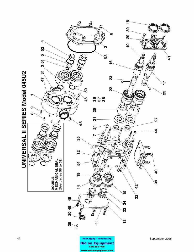
44 95-03069 September 2005
45
2
28
20
49
48
7
24
21
26
36
37
38
22
2
3
16
10
29
30
18
53
6
44
2
7
41 13
33
34
1
5
32
42
39
40
8
9
1
41
23
17
14
19
5
4
12
3
5
47
31
3 51
5
52
4
UN
IVE
RS
AL
II S
ER
IES
Mo
del
045
U2
DO
UB
LE
ME
CH
AN
ICA
L S
EA
L(S
ee
pa
ge
s 56
to
59)
46
50

4595-03069September 2005
123451234512345123451234512345123451234512345123451234512345123451234512345123451234512345123451234512345123451234512345123451234512345123451234512345123451234512345123451234512345123451234512345123451234512345123451234512345123451234512345123451234512345123451234512345123451234512345
123123123123123123123123123123123123123123123123123123123123123123123123123123123123123123123123123123123123123123123123123123123123123123123123123123123123123123123123123123
123123123123123123123123123123123123123123123123123123123123123123123123123123123123123123123123123123123123123123123123123123123123123123123123123123123123123123123123123
123412341234123412341234123412341234123412341234123412341234123412341234123412341234123412341234123412341234123412341234123412341234123412341234123412341234123412341234123412341234123412341234123412341234123412341234123412341234
123123123123123123123123123123123123123123123123123123123123123123123123123123123123123123123123123123123123123123123123123123123123123123123123123123123123123123123123123123
123123123123123123123123123123123123123123123123123123123123123123123123123123123123123123123123123123123123123123123123123123123123123123123123123123123123123123123123123
1B
ody
(Se
e S
pe
cia
l N
ote
)1
2C
ove
r,S
tand
ard
Sta
inle
ss10
1848
1 3
Ro
tor
(Se
e S
pe
cia
l N
ote
)2
4R
oto
r N
ut10
1806
2 5
Was
her,
Bel
levi
lle10
1693
2 6
Nut
, C
ove
r10
8371
8 7
Stu
d, B
od
y10
7242
8 8
Sto
p P
in
303
S
S10
1720
6 9
Do
wel
P
in,
Up
per
CD
0 0
40
R00
1 1
0K
ey,
Ro
tor
1108
262
12G
ear
Cas
e07
0 1
05
000
1G
ear
Cas
e, S
tain
less
Ste
el10
1835
1 1
3G
ear
Cas
e C
ove
r07
0 0
06
000
1G
ear
Cas
e C
ove
r, S
S10
2282
1 1
4G
ear,
RH
060
007
00
11
15
Gea
r, L
H06
0 0
07
002
1 1
6D
rive
, S
haft
1100
211
17
Sho
rt,
Sha
ft11
0022
1 1
8S
eal,
Fro
nt G
reas
e, S
td10
2829
2S
eal,
Fro
nt G
reas
e, S
tain
less
1022
902
19
Sea
l, O
il00
0 0
30
011
2 2
0S
eal,
Inp
ut00
0 0
30
012
1S
eal,
Inp
ut (
Sta
inle
ss)
1022
941
21
Bea
ring
, R
ear
060
035
00
02
22
Bea
ring
, F
ront
060
036
00
02
23
Key
, G
ear
060
037
00
02
24
Do
wel
Bus
hing
, Up
per
CD
0 1
16
000
1 2
6S
pac
er,
Bea
ring
060
055
00
32
27
Sp
acer
, G
ear
060
055
00
02
28
Key
, Mo
tor
000
073
00
31
29
Bea
ring
Ret
aine
r, S
qua
re06
0 0
80
000
2B
eari
ng R
etai
ner,
R
oun
d S
S10
1812
2 3
0C
ap S
crew
, H
ex H
d.
Zin
c P
late
d30
-351
8C
ap S
crew
, H
ex H
d.
SS
30-6
08
31
Cap
Scr
ew,
So
c. H
d.,
Bo
dy
18-8
30-6
152
32
Oil
Plu
g,3
/4-1
6 18
-800
0 0
46
004
6O
il P
lug
, 5/
16-2
4 x
3/8
18-8
1022
966
O-R
ing
, B
una
NN
7020
86
33
Lock
Nut
NO
9S
TD
23
6 0
092
34
Lock
was
her
W09
ST
D
136
009
2 3
5E
ye B
olt
, 1/
2-13
ZP
30-3
602
123123123123123123123123123123123123123123123123123123123123123123123123123123123123123123123123123123123123123123123123123123123123123123123123123123123123123123123123123123123
123123123123123123123123123123123123123123123123123123123123123123123123123123123123123123123123123123123123123123123123123123123123123123123123123123123123123123123123123123123
12341234123412341234123412341234123412341234123412341234123412341234123412341234123412341234123412341234123412341234123412341234123412341234123412341234123412341234123412341234123412341234123412341234123412341234123412341234123412341234
123123123123123123123123123123123123123123123123123123123123123123123123123123123123123123123123123123123123123123123123123123123123123123123123123123123123123123123123123123123
123456123456123456123456123456123456123456123456123456123456123456123456123456123456123456123456123456123456123456123456123456123456123456123456123456123456123456123456123456123456123456123456123456123456123456123456123456123456123456123456123456123456123456123456123456123456123456123456123456123456123456123456123456123456123456123456123456123456123456
36S
him
, F
ront
Bea
ring
0.0
02"
4046
04
37S
him
, F
ront
Bea
ring
0.0
10"
4045
92
38S
him
, F
ront
Bea
ring
0.0
50"
4045
84
39M
oun
ting
Fo
ot,
Gea
r C
ase
070
110
00
01
Mo
unti
ng F
oo
t, G
ear
Cas
e, S
S10
2286
140
Cap
Scr
ew,
So
c. H
d.
Zin
c P
late
d30
-275
4C
ap S
crew
, S
oc.
Hd
. S
S 1
8-8
30-5
034
41S
ilico
ne S
eala
nt,
RT
V00
0 14
2 3
00A
R42
Cle
ano
ut P
lug
1-1
/16-
12 S
lot
4101
32
Cle
ano
ut P
lug
1-1
/16-
12 S
S10
2297
2O
-Rin
g,
Bun
aN
7011
92
44B
ushi
ng,
Do
wel
, Lo
wer
CD
0 1
16
100
145
Do
wel
Pin
, Lo
wer
CD
0 0
40
R10
146
Do
wel
Pin
, C
ove
r, L
ow
erC
D0
040
10
01
47D
ow
el P
in,
Co
ver,
Up
per
CD
0 0
40
000
148
Was
her,
3
/8 Z
P43
-189
649
Cap
Scr
ew, H
x H
d.,
3/8
-16
x .7
5"30
-314
6C
ap S
crew
, Hx
Hd
., 3
/8-1
6 x
.75"
30-5
06
*N
ame
Pla
te00
1 0
61
002
1*
RH
DS
, #2
x 1
/8"
18
8 S
.S.
AD
0 0
62
000
4*
Gre
ase
Fit
ting
BD
0 0
92
000
4*
Pla
stic
Cap
,Gre
ase
Fit
ting
BD
0 0
93
000
4*
Plu
g,
Pla
stic
5/1
6-18
x .
530
-524
8*
Cau
tio
n La
bel
33-6
22
50O
-Rin
g,
Ro
tor
Hub
, B
una
NN
7022
42
O-R
ing
, R
oto
r H
ub,
EP
DM
E7
02
24
O-R
ing
, R
oto
r H
ub,
Flu
oro
elas
tom
erV
70
22
451
O-R
ing
, R
etai
ner
Bun
a N
N70
119
2O
-Rin
g,
Ret
aine
r E
PD
ME
70
11
9O
-Rin
g,
Ret
aine
r F
luo
roel
asto
mer
V7
01
19
52O
-Rin
g,
Ro
tor
Nut
Bun
a N
N70
227
2O
-Rin
g,
Ro
tor
Nut
EP
DM
E7
02
27
O-R
ing
, R
oto
r N
ut F
luo
roel
asto
mer
V7
02
27
53O
-Rin
g,
Co
ver
Bun
a N
N70
373
1O
-Rin
g,
Co
ver
EP
DM
E7
03
73
O-R
ing
, C
ove
r F
luo
roel
asto
mer
V7
03
73
54P
lug
, P
last
ic,
1/2
"00
0 1
21
001
6B
SH
CS
1/2
-13
x 1/
230
-514
6
123412341234123412341234123412341234123412341234123412341234123412341234123412341234123412341234123412341234123412341234
For S
tain
less
Ste
el G
ear C
ases
ITE
M
DE
SC
RIP
TIO
N
P
AR
T N
UM
BE
R
Q
TY
ITE
M
D
ES
CR
IPT
ION
PA
RT
NU
MB
ER
QT
Y
UN
IVE
RS
AL
II S
ER
IES
Mo
del
045
U2
Sp
ecia
l No
te o
n p
age
35
* N
ot
Sho
wn
AR
= A
s R
equi
red
(Om
it I
tem
48
on
Sta
inle
ss c
ases
)
8-28
-98
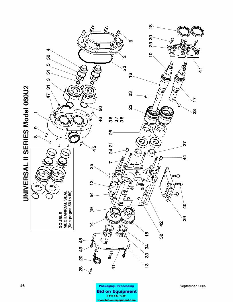
46 95-03069 September 2005
45
2
28
20
49
48
7
24
21
26
36
37
38
22
2
3
16
10
29
30
18
53
6
44
2
7
41 13
3
3 3
4
15
32
42
39
40
8
9
1
41
23
17
14
19
54
12
3
5
47
31
3 5
1 5
52
4
UN
IVE
RS
AL
II S
ER
IES
Mo
del
060
U2
DO
UB
LE
ME
CH
AN
ICA
L S
EA
L(S
ee
pa
ge
s 56
to
59)
46
50
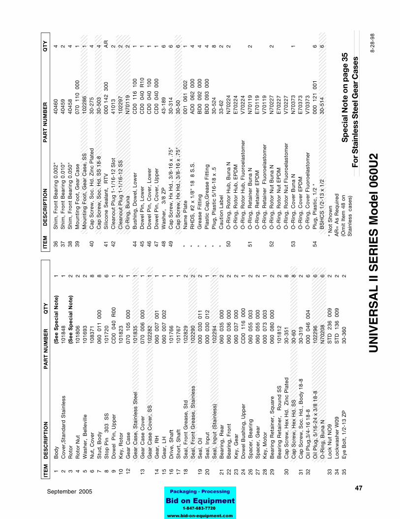
4795-03069September 2005
123451234512345123451234512345123451234512345123451234512345123451234512345123451234512345123451234512345123451234512345123451234512345123451234512345123451234512345123451234512345123451234512345123451234512345123451234512345123451234512345123451234512345123451234512345123451234512345
123123123123123123123123123123123123123123123123123123123123123123123123123123123123123123123123123123123123123123123123123123123123123123123123123123123123123123123123123
123412341234123412341234123412341234123412341234123412341234123412341234123412341234123412341234123412341234123412341234123412341234123412341234123412341234123412341234123412341234123412341234123412341234123412341234123412341234
123412341234123412341234123412341234123412341234123412341234123412341234123412341234123412341234123412341234123412341234123412341234123412341234123412341234123412341234123412341234123412341234123412341234123412341234123412341234
123123123123123123123123123123123123123123123123123123123123123123123123123123123123123123123123123123123123123123123123123123123123123123123123123123123123123123123123123
123123123123123123123123123123123123123123123123123123123123123123123123123123123123123123123123123123123123123123123123123123123123123123123123123123123123123123123123123
1B
ody
(Se
e S
pe
cia
l N
ote
)1
2C
ove
r,S
tand
ard
Sta
inle
ss10
1848
1 3
Ro
tor
(Se
e S
pe
cia
l N
ote
)2
4R
oto
r N
ut10
1806
2 5
Was
her,
Bel
levi
lle10
1693
2 6
Nut
, C
ove
r10
8371
8 7
Stu
d, B
od
y06
0 0
11
000
8 8
Sto
p P
in
303
S
S10
1720
6 9
Do
wel
P
in,
Up
per
CD
0 0
40
R00
1 1
0K
ey,
Ro
tor
1018
232
12G
ear
Cas
e07
0 1
05
000
1G
ear
Cas
e, S
tain
less
Ste
el10
1835
1 1
3G
ear
Cas
e C
ove
r07
0 0
06
000
1G
ear
Cas
e C
ove
r, S
S10
2282
1 1
4G
ear,
RH
060
007
00
11
15
Gea
r, L
H06
0 0
07
002
1 1
6D
rive
, S
haft
1017
661
17
Sho
rt,
Sha
ft10
1767
1 1
8S
eal,
Fro
nt G
reas
e, S
td10
2829
2S
eal,
Fro
nt G
reas
e, S
tain
less
1022
902
19
Sea
l, O
il00
0 0
30
011
2 2
0S
eal,
Inp
ut00
0 0
30
012
1S
eal,
Inp
ut (
Sta
inle
ss)
1022
941
21
Bea
ring
, R
ear
060
035
00
02
22
Bea
ring
, F
ront
060
036
00
02
23
Key
, G
ear
060
037
00
02
24
Do
wel
Bus
hing
, Up
per
CD
0 1
16
000
1 2
6S
pac
er,
Bea
ring
060
055
00
32
27
Sp
acer
, G
ear
060
055
00
02
28
Key
, Mo
tor
000
073
00
31
29
Bea
ring
Ret
aine
r, S
qua
re06
0 0
80
000
2B
eari
ng R
etai
ner,
R
oun
d S
S10
1812
2 3
0C
ap S
crew
, H
ex H
d.
Zin
c P
late
d30
-351
8C
ap S
crew
, H
ex H
d.
SS
30-6
08
31
Cap
Scr
ew,
So
c. H
d.,
Bo
dy
18-8
30-3
192
32
Oil
Plu
g,3
/4-1
6 18
-800
0 0
46
004
6O
il P
lug
, 5/
16-2
4 x
3/8
18-8
1022
966
O-R
ing
, B
una
NN
7020
86
33
Lock
Nut
NO
9S
TD
23
6 0
092
34
Lock
was
her
W09
ST
D
136
009
2 3
5E
ye B
olt
, 1/
2-13
ZP
30-3
602
123123123123123123123123123123123123123123123123123123123123123123123123123123123123123123123123123123123123123123123123123123123123123123123123123123123123123123123123123123
123123123123123123123123123123123123123123123123123123123123123123123123123123123123123123123123123123123123123123123123123123123123123123123123123123123123123123123123123123
123123123123123123123123123123123123123123123123123123123123123123123123123123123123123123123123123123123123123123123123123123123123123123123123123123123123123123123123123123
123123123123123123123123123123123123123123123123123123123123123123123123123123123123123123123123123123123123123123123123123123123123123123123123123123123123123123123123123123123
12345123451234512345123451234512345123451234512345123451234512345123451234512345123451234512345123451234512345123451234512345123451234512345123451234512345123451234512345123451234512345123451234512345123451234512345123451234512345123451234512345123451234512345123451234512345123451234512345
36S
him
, F
ront
Bea
ring
0.0
02"
4046
04
37S
him
, F
ront
Bea
ring
0.0
10"
4045
92
38S
him
, F
ront
Bea
ring
0.0
50"
4045
84
39M
oun
ting
Fo
ot,
Gea
r C
ase
070
110
00
01
Mo
unti
ng F
oo
t, G
ear
Cas
e, S
S10
2286
140
Cap
Scr
ew,
So
c. H
d.
Zin
c P
late
d30
-275
4C
ap S
crew
, S
oc.
Hd
. S
S 1
8-8
30-5
034
41S
ilico
ne S
eala
nt,
RT
V00
0 14
2 3
00A
R42
Cle
ano
ut P
lug
1-1
/16-
12 S
lot
4101
32
Cle
ano
ut P
lug
1-1
/16-
12 S
S10
2297
2O
-Rin
g,
Bun
aN
7011
92
44B
ushi
ng,
Do
wel
, Lo
wer
CD
0 1
16
100
145
Do
wel
Pin
, Lo
wer
CD
0 0
40
R10
146
Do
wel
Pin
, C
ove
r, L
ow
erC
D0
040
10
01
47D
ow
el P
in,
Co
ver,
Up
per
CD
0 0
40
000
148
Was
her,
3
/8 Z
P43
-189
649
Cap
Scr
ew, H
x H
d.,
3/8
-16
x .7
5"30
-314
6C
ap S
crew
, Hx
Hd
., 3
/8-1
6 x
.75"
30-5
06
*N
ame
Pla
te00
1 0
61
002
1*
RH
DS
, #2
x 1
/8"
18
8 S
.S.
AD
0 0
62
000
4*
Gre
ase
Fit
ting
BD
0 0
92
000
4*
Pla
stic
Cap
,Gre
ase
Fit
ting
BD
0 0
93
000
4*
Plu
g,
Pla
stic
5/1
6-18
x .
530
-524
8*
Cau
tio
n La
bel
33-6
22
50O
-Rin
g,
Ro
tor
Hub
, B
una
NN
7022
42
O-R
ing
, R
oto
r H
ub,
EP
DM
E7
02
24
O-R
ing
, R
oto
r H
ub,
Flu
oro
elas
tom
erV
70
22
451
O-R
ing
, R
etai
ner
Bun
a N
N70
119
2O
-Rin
g,
Ret
aine
r E
PD
ME
70
11
9O
-Rin
g,
Ret
aine
r F
luo
roel
asto
mer
V7
01
19
52O
-Rin
g,
Ro
tor
Nut
Bun
a N
N70
227
2O
-Rin
g,
Ro
tor
Nut
EP
DM
E7
02
27
O-R
ing
, R
oto
r N
ut F
luo
roel
asto
mer
V7
02
27
53O
-Rin
g,
Co
ver
Bun
a N
N70
373
1O
-Rin
g,
Co
ver
EP
DM
E7
03
73
O-R
ing
, C
ove
r F
luo
roel
asto
mer
V7
03
73
54P
lug
, P
last
ic,
1/2
"00
0 1
21
001
6B
SH
CS
1/2
-13
x 1/
230
-514
6
123412341234123412341234123412341234123412341234123412341234123412341234123412341234123412341234123412341234123412341234
For S
tain
less
Ste
el G
ear C
ases
ITE
M
DE
SC
RIP
TIO
N
P
AR
T N
UM
BE
R
Q
TY
ITE
M
D
ES
CR
IPT
ION
PA
RT
NU
MB
ER
QT
Y
UN
IVE
RS
AL
II S
ER
IES
Mo
del
060
U2
Sp
ecia
l No
te o
n p
age
35
* N
ot
Sho
wn
AR
= A
s R
equi
red
(Om
it I
tem
48
on
Sta
inle
ss c
ases
)
8-28
-98

48 95-03069 September 2005
UN
IVE
RS
AL
II S
ER
IES
Mo
del
130
U2
45
2
28
20
49
48
7
24
21
26
36
37
38
22
2
3
16
10
29
30
18
53
6
44
2
7
41 13
33
34
15
32
42
39
40
8
9
1
41
23
17
47
31
3 5
1 5
52
4
14
1
9
54
1
2
35
DO
UB
LE
ME
CH
AN
ICA
L S
EA
L(S
ee
pa
ge
s 56
to
59)
46
50
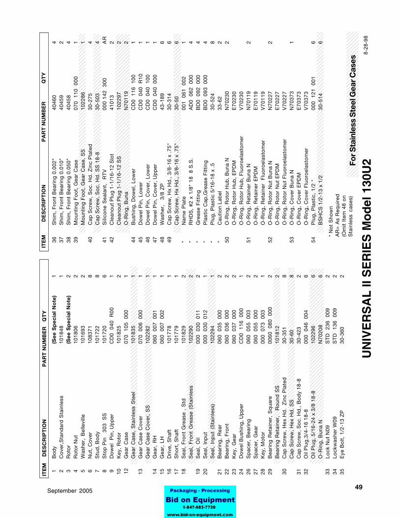
4995-03069September 2005
123123123123123123123123123123123123123123123123123123123123123123123123123123123123123123123123123123123123123123123123123123123123123123123123123123123123123123123123123123
12345123451234512345123451234512345123451234512345123451234512345123451234512345123451234512345123451234512345123451234512345123451234512345123451234512345123451234512345123451234512345123451234512345123451234512345123451234512345123451234512345123451234512345123451234512345123451234512345
123123123123123123123123123123123123123123123123123123123123123123123123123123123123123123123123123123123123123123123123123123123123123123123123123123123123123123123123123123123
123123123123123123123123123123123123123123123123123123123123123123123123123123123123123123123123123123123123123123123123123123123123123123123123123123123123123123123123123123123
1234512345123451234512345123451234512345123451234512345123451234512345123451234512345123451234512345123451234512345123451234512345123451234512345123451234512345123451234512345123451234512345123451234512345123451234512345123451234512345123451234512345123451234512345123451234512345123451234512345
123123123123123123123123123123123123123123123123123123123123123123123123123123123123123123123123123123123123123123123123123123123123123123123123123123123123123123123123123123
123123123123123123123123123123123123123123123123123123123123123123123123123123123123123123123123123123123123123123123123123123123123123123123123123123123123123123123123123123
123123123123123123123123123123123123123123123123123123123123123123123123123123123123123123123123123123123123123123123123123123123123123123123123123123123123123123123123123123
123123123123123123123123123123123123123123123123123123123123123123123123123123123123123123123123123123123123123123123123123123123123123123123123123123123123123123123123123123123
123123123123123123123123123123123123123123123123123123123123123123123123123123123123123123123123123123123123123123123123123123123123123123123123123123123123123123123123123123
123123123123123123123123123123123123123123123123123123123123123123123123123123123123123123123123123123123123123123123123123123123123123123123123123123123123123123123123123123
123123123123123123123123123123123123123123123123123123123123123123123123123123123123123123123123123123123123123123123123123123123123123123123123123123123123123123123123123123123
1234123412341234123412341234123412341234123412341234123412341234123412341234123412341234123412341234123412341234123412341234123412341234123412341234123412341234123412341234
ITE
M
DE
SC
RIP
TIO
N
P
AR
T N
UM
BE
RQ
TY
ITE
M
DE
SC
RIP
TIO
N
PA
RT
NU
MB
ER
Q
TY
UN
IVE
RS
AL
II S
ER
IES
Mo
del
130
U2
* N
ot
Sho
wn
AR
= A
s R
equi
red
(Om
it I
tem
48
on
Sta
inle
ss c
ases
)
8-28
-98
For S
tain
less
Ste
el G
ear C
ases
36S
him
, F
ront
Bea
ring
0.0
02"
4046
04
37S
him
, F
ront
Bea
ring
0.0
10"
4045
92
38S
him
, F
ront
Bea
ring
0.0
50"
4045
84
39M
oun
ting
Fo
ot,
Gea
r C
ase
070
110
00
01
Mo
unti
ng F
oo
t, G
ear
Cas
e, S
S10
2286
140
Cap
Scr
ew,
So
c. H
d.
Zin
c P
late
d30
-275
4C
ap S
crew
, S
oc.
Hd
. S
S 1
8-8
30-5
034
41S
ilico
ne S
eala
nt,
RT
V00
0 14
2 3
00A
R42
Cle
ano
ut P
lug
1-1
/16-
12 S
lot
4101
32
Cle
ano
ut P
lug
1-1
/16-
12 S
S10
2297
2O
-Rin
g,
Bun
aN
7011
92
44B
ushi
ng,
Do
wel
, Lo
wer
CD
0 1
16
100
145
Do
wel
Pin
, Lo
wer
CD
0 0
40
R10
146
Do
wel
Pin
, C
ove
r, L
ow
erC
D0
040
10
01
47D
ow
el P
in,
Co
ver,
Up
per
CD
0 0
40
000
148
Was
her,
3
/8 Z
P43
-189
649
Cap
Scr
ew, H
x H
d.,
3/8
-16
x .7
5"30
-314
6C
ap S
crew
, Hx
Hd
., 3
/8-1
6 x
.75"
30-5
06
*N
ame
Pla
te00
1 0
61
002
1*
RH
DS
, #2
x 1
/8"
18
8 S
.S.
AD
0 0
62
000
4*
Gre
ase
Fit
ting
BD
0 0
92
000
4*
Pla
stic
Cap
,Gre
ase
Fit
ting
BD
0 0
93
000
4*
Plu
g,
Pla
stic
5/1
6-18
x .
530
-524
8*
Cau
tio
n La
bel
33-6
22
50O
-Rin
g,
Ro
tor
Hub
, B
una
NN
7023
02
O-R
ing
, R
oto
r H
ub,
EP
DM
E7
02
30
O-R
ing
, R
oto
r H
ub,
Flu
oro
elas
tom
erV
70
23
051
O-R
ing
, R
etai
ner
Bun
a N
N70
119
2O
-Rin
g,
Ret
aine
r E
PD
ME
70
11
9O
-Rin
g,
Ret
aine
r F
luo
roel
asto
mer
V7
01
19
52O
-Rin
g,
Ro
tor
Nut
Bun
a N
N70
227
2O
-Rin
g,
Ro
tor
Nut
EP
DM
E7
02
27
O-R
ing
, R
oto
r N
ut F
luo
roel
asto
mer
V7
02
27
53O
-Rin
g,
Co
ver
Bun
a N
N70
373
1O
-Rin
g,
Co
ver
EP
DM
E7
03
73
O-R
ing
, C
ove
r F
luo
roel
asto
mer
V7
03
73
54P
lug
, P
last
ic,
1/2
"00
0 1
21
001
6B
SH
CS
1/2
-13
x 1/
230
-514
6
1B
ody
(Se
e S
pe
cia
l N
ote
)1
2C
ove
r,S
tand
ard
Sta
inle
ss10
1848
1 3
Ro
tor
(Se
e S
pe
cia
l N
ote
)2
4R
oto
r N
ut10
1806
2 5
Was
her,
Bel
levi
lle10
1693
2 6
Nut
, C
ove
r10
8371
8 7
Stu
d, B
od
y10
1722
8 8
Sto
p P
in
303
S
S10
1720
6 9
Do
wel
P
in,
Up
per
CD
0 0
40
R00
1 1
0K
ey,
Ro
tor
1018
252
12G
ear
Cas
e07
0 1
05
000
1G
ear
Cas
e, S
tain
less
Ste
el10
1835
1 1
3G
ear
Cas
e C
ove
r07
0 0
06
000
1G
ear
Cas
e C
ove
r, S
S10
2282
1 1
4G
ear,
RH
060
007
00
11
15
Gea
r, L
H06
0 0
07
002
1 1
6D
rive
, S
haft
1017
781
17
Sho
rt,
Sha
ft10
1779
1 1
8S
eal,
Fro
nt G
reas
e ,
Std
1018
292
Sea
l, F
ront
Gre
ase
(Sta
inle
ss10
2290
2 1
9S
eal,
Oil
000
030
01
12
20
Sea
l, In
put
000
030
01
21
Sea
l, In
put
(S
tain
less
)10
2294
1 2
1B
eari
ng,
Rea
r06
0 0
35
000
2 2
2B
eari
ng,
Fro
nt06
0 0
36
000
2 2
3K
ey,
Gea
r06
0 0
37
000
2 2
4D
ow
el B
ushi
ng, U
pp
erC
D0
116
00
01
26
Sp
acer
, B
eari
ng06
0 0
55
003
2 2
7S
pac
er,
Gea
r06
0 0
55
000
2 2
8K
ey, M
oto
r00
0 0
73
003
1 2
9B
eari
ng R
etai
ner,
Sq
uare
0060
08
0 0
002
Bea
ring
Ret
aine
r,
Ro
und
SS
1018
122
30
Cap
Scr
ew,
Hex
Hd
. Z
inc
Pla
ted
30-3
518
Cap
Scr
ew,
Hex
Hd
. S
S30
-60
8 3
1C
ap S
crew
, S
oc.
Hd
., B
od
y 18
-830
-423
2 3
2O
il P
lug
,3/4
-16
18-8
000
046
00
46
Oil
Plu
g,
5/16
-24
x 3/
8 18
-810
2296
6O
-Rin
g,
Bun
a N
N70
208
6 3
3Lo
ck N
ut N
09S
TD
23
6 0
092
34
Lock
was
her
W09
ST
D
136
009
2 3
5E
ye B
olt
, 1/
2-13
ZP
30-3
602
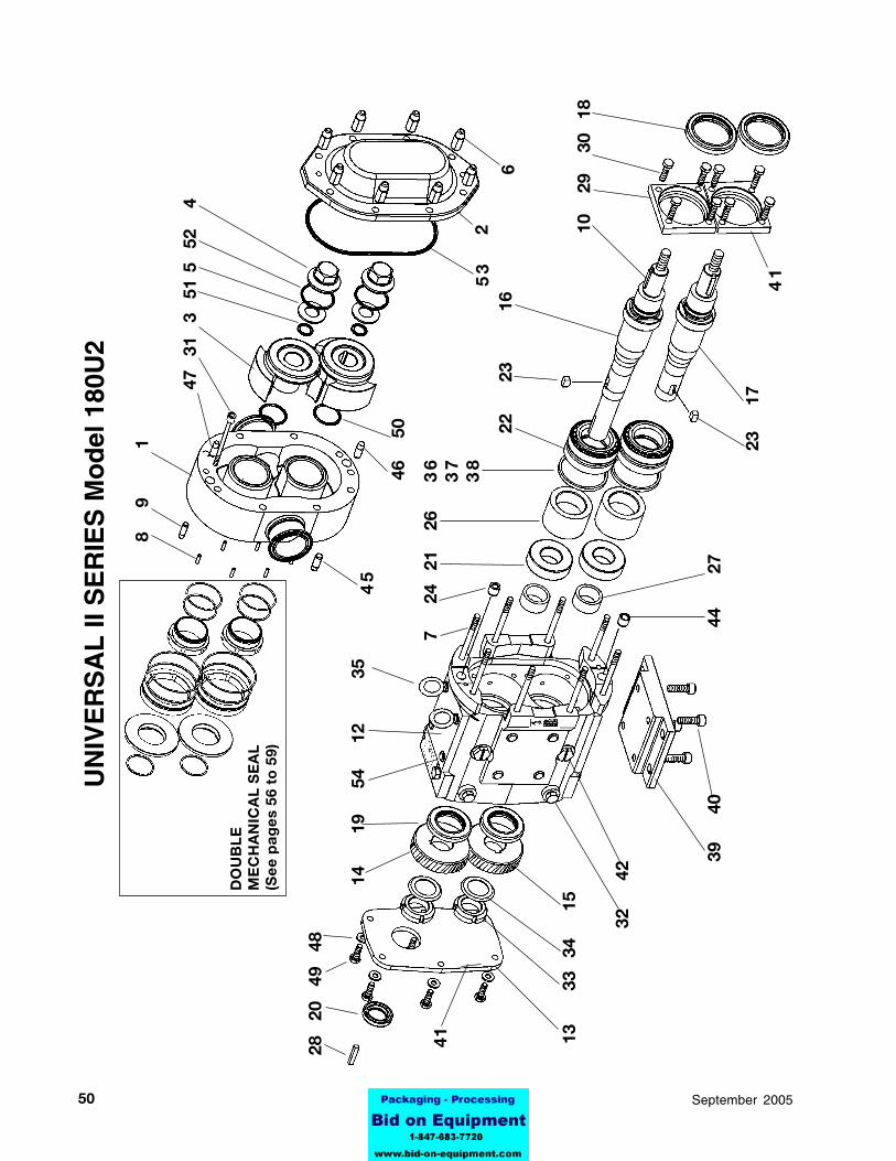
50 95-03069 September 2005
45
2
28
20
49
48
7
24
21
26
36
37
38
22
2
3
16
10
29
3
0 1
8
53
6
44
2
7
41 13
33
34
1
5
39
40
8
9
1
41
23
17
14
1
9
54
1
2
35
47
31
3 5
1 5
52
4
UN
IVE
RS
AL
II S
ER
IES
Mo
del
180
U2
DO
UB
LE
ME
CH
AN
ICA
L S
EA
L(S
ee
pa
ge
s 56
to
59)
32
42
46
50

5195-03069September 2005
12345123451234512345123451234512345123451234512345123451234512345123451234512345123451234512345123451234512345123451234512345123451234512345123451234512345123451234512345123451234512345F
or S
tain
less
Ste
el G
ear C
ases
123123123123123123123123123123123123123123123123123123123123123123123123123123123123123123123123123123123123123123123123123123123123123123123123123123123123123123123123123
123123123123123123123123123123123123123123123123123123123123123123123123123123123123123123123123123123123123123123123123123123123123123123123123123123123123123123123123123
123412341234123412341234123412341234123412341234123412341234123412341234123412341234123412341234123412341234123412341234123412341234123412341234123412341234123412341234123412341234123412341234123412341234123412341234123412341234
123123123123123123123123123123123123123123123123123123123123123123123123123123123123123123123123123123123123123123123123123123123123123123123123123123123123123123123123
12341234123412341234123412341234123412341234123412341234123412341234123412341234123412341234123412341234123412341234123412341234123412341234123412341234123412341234123412341234123412341234123412341234123412341234123412341234
123123123123123123123123123123123123123123123123123123123123123123123123123123123123123123123123123123123123123123123123123123123123123123123123123123123123123123123123123
123451234512345123451234512345123451234512345123451234512345123451234512345123451234512345123451234512345123451234512345123451234512345123451234512345123451234512345123451234512345123451234512345123451234512345123451234512345123451234512345123451234512345123451234512345123451234512345
123123123123123123123123123123123123123123123123123123123123123123123123123123123123123123123123123123123123123123123123123123123123123123123123123123123123123123123123123123123
ITE
M
DE
SC
RIP
TIO
N
P
AR
T N
UM
BE
RQ
TY
UN
IVE
RS
AL
II S
ER
IES
Mo
del
180
U2
ITE
M
D
ES
CR
IPT
ION
PA
RT
NU
MB
ER
QT
Y
Sp
ecia
l No
te o
n p
age
35
* N
ot
Sho
wn
AR
= A
s R
equi
red
(Om
it I
tem
48
on
Sta
inle
ss C
ases
)
123123123123123123123123123123123123123123123123123123123123123123123123123123123123123123123123123123123123123123123123123123123123123123123123123123123123123123123123123123123
12345123451234512345123451234512345123451234512345123451234512345123451234512345123451234512345123451234512345123451234512345123451234512345123451234512345123451234512345123451234512345123451234512345123451234512345123451234512345123451234512345123451234512345123451234512345123451234512345
123123123123123123123123123123123123123123123123123123123123123123123123123123123123123123123123123123123123123123123123123123123123123123123123123123123123123123123123123123
123123123123123123123123123123123123123123123123123123123123123123123123123123123123123123123123123123123123123123123123123123123123123123123123123123123123123123123123123123
8-28
-98
39M
oun
ting
Fo
ot,
Gea
r C
ase
230
110
00
01
Mo
unti
ng F
oo
t, G
ear
Cas
e S
S10
2287
140
Cap
Scr
ew,
So
c. H
d.
Z
P30
-111
4C
ap S
crew
, S
oc.
Hd
. 18
-830
-44
441
Sili
cone
Sea
lant
, R
TV
000
142
300
AR
42C
lean
out
Plu
g 1
-1/1
6-12
Slo
t41
013
2C
lean
out
Plu
g 1
-1/1
6-12
SS
1022
972
O-R
ing
, B
una
NN
7011
92
44B
ushi
ng,
Do
wel
, Lo
wer
CD
0 1
16
100
145
Do
wel
Pin
, Lo
wer
, G
ear
case
CD
0 0
40
R10
146
Do
wel
Pin
, C
ove
r, L
ow
erG
D0
040
10
01
47D
ow
el P
in,
Co
ver,
Up
per
GD
0 0
40
000
148
Was
her,
Z
P43
-108
849
Cap
Scr
ew, H
x H
d. 3
/8-1
6 x
.75"
30-3
148
Cap
Scr
ew, H
x H
d. 3
/8-1
6 x
.75"
30-5
08
*N
ame
Pla
te00
1 0
61
002
1*
RH
DS
, #2
x 1
/8"
18
8 S
.S.
AD
0 0
62
000
4*
Gre
ase
Fit
ting
BD
0 0
92
000
4*
Pla
stic
Cap
,Gre
ase
Fit
ting
BD
0 0
93
000
4*
Cau
tio
n La
bel
33-6
22
50O
-Rin
g,
Ro
tor
Hub
, B
una
NN
7023
02
O-R
ing
, R
oto
r H
ub,
EP
DM
E7
02
30
O-R
ing
, R
oto
r H
ub,
Flu
oro
elas
tom
erV
70
23
051
O-R
ing
, R
etai
ner
Bun
a N
N70
122
2O
-Rin
g,
Ret
aine
r E
PD
ME
70
12
2O
-Rin
g,
Ret
aine
r F
luo
roel
asto
mer
V7
01
22
52O
-Rin
g,
Ro
tor
Nut
Bun
a N
N70
235
2O
-Rin
g,
Ro
tor
Nut
EP
DM
E7
02
35
O-R
ing
, R
oto
r N
ut F
luo
roel
asto
mer
V7
02
35
53O
-Rin
g,
Co
ver
Bun
a N
N70
381
1O
-Rin
g,
Co
ver
EP
DM
E7
03
81
O-R
ing
, C
ove
r F
luo
roel
asto
mer
V7
03
81
54P
lug
, P
last
ic,
1/2
"00
0 1
21
001
6B
SH
CS
1/2
-13
x 1/
230
-514
6
1
Bod
y(S
ee
Sp
ec
ial
No
te)
1
2C
ove
r, S
tand
ard
Sta
inle
ss10
1851
1 3
Ro
tor
(Se
e S
pe
cia
l N
ote
)2
4
Ro
tor
Nut
1018
072
5W
ashe
r, B
elle
ville
1016
942
6N
ut,
Co
ver
1083
728
7S
tud
, Bo
dy
1072
438
8S
top
Pin
3
03
SS
1017
206
9
Do
wel
P
in,
Up
per
GD
0 0
40
R00
1 1
0K
ey,
Ro
tor
1109
272
12G
ear
Cas
e23
0 1
05
000
1G
ear
Cas
e, S
tain
less
Ste
el10
1837
1 1
3G
ear
Cas
e C
ove
r23
0 0
06
000
1G
ear
Cas
e C
ove
r, S
S10
2283
1 1
4G
ear,
RH
200
007
001
1 1
5G
ear,
LH
200
007
00
21
16
Dri
ve,
Sha
ft11
0023
1 1
7S
hort
, S
haft
1100
241
18
Sea
l, F
ront
Gre
ase
ST
D
030
002
2S
eal,
Fro
nt G
reas
e10
2291
2 1
9S
eal,
Gre
ase
ST
D
119
002
2 2
0S
eal,
Inp
utS
TD
03
0 0
061
Sea
l, In
put
1022
951
21
Bea
ring
, R
ear
200
035
000
2 2
2B
eari
ng,
Fro
nt20
0 0
36
000
2 2
3K
ey,
Gea
r20
0 0
37
000
2 2
4D
ow
el B
ushi
ng, U
pp
erC
D0
116
00
01
26
Sp
acer
, B
eari
ng40
752
2 2
7S
pac
er,
Gea
r20
0 0
55
000
2 2
8K
ey, M
oto
r00
0 0
37
004
1 2
9B
eari
ng R
etai
ner,
Fro
nt,
Sq
uare
220
080
00
02
Bea
ring
Ret
aine
r, F
ront
, R
oun
d10
813
230
Cap
Scr
ew,H
x.H
d.3
/8-1
6 Z
P30
-351
8C
ap S
crew
,Hx.
Hd
.3/8
-16
18-8
30-6
08
31
Cap
Scr
ew,
So
c. H
d.
18-8
30-3
262
32
Oil
Plu
g,
w
/Was
her
000
046
00
46
Oil
Plu
g,
1022
966
O-R
ing
, B
una
NN
7020
86
33Lo
ck N
ut N
11S
TD
23
6 0
112
34Lo
ckw
ashe
r W
11S
TD
13
6 0
112
35E
ye B
olt
, 1/
2-13
30-3
602
36S
him
, F
ront
Bea
ring
0.0
02"
220
054
00
24
37S
him
, F
ront
Bea
ring
0.0
10"
220
054
010
238
Shi
m,
Fro
nt B
eari
ng 0
.050
"22
0 0
54
050
4

52 95-03069 September 2005
45
2
28
20
49
48
7
24
21
26
36
37
38
22
23
16
10
29
30
18
53
6
44
2
7
41 13
33
34
15
39
40
8
9
1
41
23
17
14
1
9
54
1
2
35
47 3
1 3
5
1 5
52
4
UN
IVE
RS
AL
II S
ER
IES
Mo
del
220
U2
DO
UB
LE
ME
CH
AN
ICA
L S
EA
L(S
ee
pa
ge
s 56
to
59)
32
42
46
50
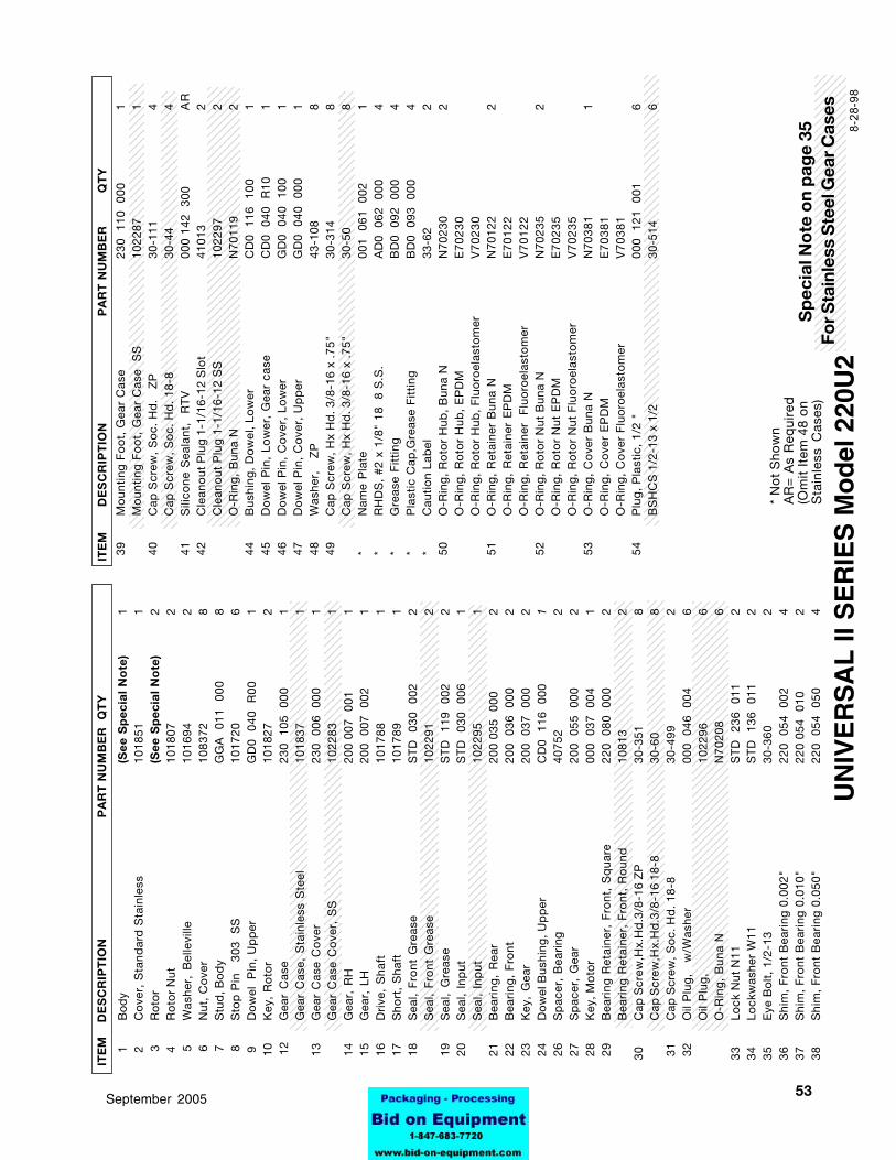
5395-03069September 2005
123123123123123123123123123123123123123123123123123123123123123123123123123123123123123123123123123123123123123123123123123123123123123123123123123123123123123123123123123
123412341234123412341234123412341234123412341234123412341234123412341234123412341234123412341234123412341234123412341234123412341234123412341234123412341234123412341234123412341234123412341234123412341234123412341234123412341234
123123123123123123123123123123123123123123123123123123123123123123123123123123123123123123123123123123123123123123123123123123123123123123123123123123123123123123123123123
123123123123123123123123123123123123123123123123123123123123123123123123123123123123123123123123123123123123123123123123123123123123123123123123123123123123123123123123
123123123123123123123123123123123123123123123123123123123123123123123123123123123123123123123123123123123123123123123123123123123123123123123123123123123123123123123123
123123123123123123123123123123123123123123123123123123123123123123123123123123123123123123123123123123123123123123123123123123123123123123123123123123123123123123123123123
123456123456123456123456123456123456123456123456123456123456123456123456123456123456123456123456123456123456123456123456123456123456123456123456123456123456123456123456123456123456123456123456123456123456123456123456123456123456123456123456123456123456123456123456123456123456123456123456123456123456123456123456123456123456123456123456123456
12345123451234512345123451234512345123451234512345123451234512345123451234512345123451234512345123451234512345123451234512345123451234512345123451234512345123451234512345123451234512345
123123123123123123123123123123123123123123123123123123123123123123123123123123123123123123123123123123123123123123123123123123123123123123123123123123123123123123123123123123123
123123123123123123123123123123123123123123123123123123123123123123123123123123123123123123123123123123123123123123123123123123123123123123123123123123123123123123123123123123123
123456123456123456123456123456123456123456123456123456123456123456123456123456123456123456123456123456123456123456123456123456123456123456123456123456123456123456123456123456123456123456123456123456123456123456123456123456123456123456123456123456123456123456123456123456123456123456123456123456123456123456123456123456123456123456123456123456123456
123123123123123123123123123123123123123123123123123123123123123123123123123123123123123123123123123123123123123123123123123123123123123123123123123123123123123123123123123123
123123123123123123123123123123123123123123123123123123123123123123123123123123123123123123123123123123123123123123123123123123123123123123123123123123123123123123123123123123
For S
tain
less
Ste
el G
ear C
ases
1
Bod
y(S
ee
Sp
ec
ial
No
te)
1
2C
ove
r, S
tand
ard
Sta
inle
ss10
1851
1 3
Ro
tor
(Se
e S
pe
cia
l N
ote
)2
4
Ro
tor
Nut
1018
072
5W
ashe
r, B
elle
ville
1016
942
6N
ut,
Co
ver
1083
728
7S
tud
, Bo
dy
GG
A
011
000
8 8
Sto
p P
in
303
S
S10
1720
6
9D
ow
el
Pin
, U
pp
erG
D0
040
R
001
10
Key
, R
oto
r10
1827
212
Gea
r C
ase
230
105
00
01
Gea
r C
ase,
Sta
inle
ss S
teel
1018
371
13
Gea
r C
ase
Co
ver
230
006
00
01
Gea
r C
ase
Co
ver,
SS
1022
831
14
Gea
r, R
H20
0 00
7 0
011
15
Gea
r, L
H20
0 0
07
002
1 1
6D
rive
, S
haft
1017
881
17
Sho
rt,
Sha
ft10
1789
1 1
8S
eal,
Fro
nt G
reas
eS
TD
03
0 0
022
Sea
l, F
ront
Gre
ase
1022
912
19
Sea
l, G
reas
eS
TD
11
9 0
022
20
Sea
l, In
put
ST
D
030
006
1S
eal,
Inp
ut10
2295
1 2
1B
eari
ng,
Rea
r20
0 03
5 0
002
22
Bea
ring
, F
ront
200
036
00
02
23
Key
, G
ear
200
037
00
02
24
Do
wel
Bus
hing
, Up
per
CD
0 1
16
000
1 2
6S
pac
er,
Bea
ring
4075
22
27
Sp
acer
, G
ear
200
055
00
02
28
Key
, Mo
tor
000
037
00
41
29
Bea
ring
Ret
aine
r, F
ront
, S
qua
re22
0 0
80
000
2B
eari
ng R
etai
ner,
Fro
nt,
Ro
und
1081
32
30C
ap S
crew
,Hx.
Hd
.3/8
-16
ZP
30-3
518
Cap
Scr
ew,H
x.H
d.3
/8-1
6 18
-830
-60
8 3
1C
ap S
crew
, S
oc.
Hd
. 18
-830
-499
2 3
2O
il P
lug
,
w/W
ashe
r00
0 0
46
004
6O
il P
lug
,10
2296
6O
-Rin
g,
Bun
a N
N70
208
633
Lock
Nut
N11
ST
D
236
011
234
Lock
was
her
W11
ST
D
136
011
235
Eye
Bo
lt,
1/2-
1330
-360
236
Shi
m,
Fro
nt B
eari
ng 0
.002
"22
0 0
54
002
437
Shi
m,
Fro
nt B
eari
ng 0
.010
"22
0 05
4 0
102
38S
him
, F
ront
Bea
ring
0.0
50"
220
054
05
04
39M
oun
ting
Fo
ot,
Gea
r C
ase
230
110
00
01
Mo
unti
ng F
oo
t, G
ear
Cas
e S
S10
2287
140
Cap
Scr
ew,
So
c. H
d.
Z
P30
-111
4C
ap S
crew
, S
oc.
Hd
. 18
-830
-44
441
Sili
cone
Sea
lant
, R
TV
000
142
300
AR
42C
lean
out
Plu
g 1
-1/1
6-12
Slo
t41
013
2C
lean
out
Plu
g 1
-1/1
6-12
SS
1022
972
O-R
ing
, B
una
NN
7011
92
44B
ushi
ng,
Do
wel
, Lo
wer
CD
0 1
16
100
145
Do
wel
Pin
, Lo
wer
, G
ear
case
CD
0 0
40
R10
146
Do
wel
Pin
, C
ove
r, L
ow
erG
D0
040
10
01
47D
ow
el P
in,
Co
ver,
Up
per
GD
0 0
40
000
148
Was
her,
Z
P43
-108
849
Cap
Scr
ew, H
x H
d. 3
/8-1
6 x
.75"
30-3
148
Cap
Scr
ew, H
x H
d. 3
/8-1
6 x
.75"
30-5
08
*N
ame
Pla
te00
1 0
61
002
1*
RH
DS
, #2
x 1
/8"
18
8 S
.S.
AD
0 0
62
000
4*
Gre
ase
Fit
ting
BD
0 0
92
000
4*
Pla
stic
Cap
,Gre
ase
Fit
ting
BD
0 0
93
000
4*
Cau
tio
n La
bel
33-6
22
50O
-Rin
g,
Ro
tor
Hub
, B
una
NN
7023
02
O-R
ing
, R
oto
r H
ub,
EP
DM
E7
02
30
O-R
ing
, R
oto
r H
ub,
Flu
oro
elas
tom
erV
70
23
051
O-R
ing
, R
etai
ner
Bun
a N
N70
122
2O
-Rin
g,
Ret
aine
r E
PD
ME
70
12
2O
-Rin
g,
Ret
aine
r F
luo
roel
asto
mer
V7
01
22
52O
-Rin
g,
Ro
tor
Nut
Bun
a N
N70
235
2O
-Rin
g,
Ro
tor
Nut
EP
DM
E7
02
35
O-R
ing
, R
oto
r N
ut F
luo
roel
asto
mer
V7
02
35
53O
-Rin
g,
Co
ver
Bun
a N
N70
381
1O
-Rin
g,
Co
ver
EP
DM
E7
03
81
O-R
ing
, C
ove
r F
luo
roel
asto
mer
V7
03
81
54P
lug
, P
last
ic,
1/2
"00
0 1
21
001
6B
SH
CS
1/2
-13
x 1/
230
-514
6
ITE
M
DE
SC
RIP
TIO
N
P
AR
T N
UM
BE
RQ
TY
UN
IVE
RS
AL
II S
ER
IES
Mo
del
220
U2
ITE
M
D
ES
CR
IPT
ION
PA
RT
NU
MB
ER
QT
Y
Sp
ecia
l No
te o
n p
age
35
* N
ot
Sho
wn
AR
= A
s R
equi
red
(Om
it I
tem
48
on
Sta
inle
ss C
ases
)
8-28
-98

54 95-03069 September 2005
22
23
16
10
2
9 30
18
3
1 3
5
1 5
52
4
UN
IVE
RS
AL
II S
ER
IES
Mo
del
320
U2
58
2
28
20
49
48
7
24
21
26
46
50
3
7,38
63
64
53
6
44
2
7
41 13
33
12
39
40
8
9
1
41
23
17
14
1
9
54
61
35
DO
UB
LE
ME
CH
AN
ICA
L S
EA
L(S
ee
pa
ge
59)
32
42
56 55 57
14
59
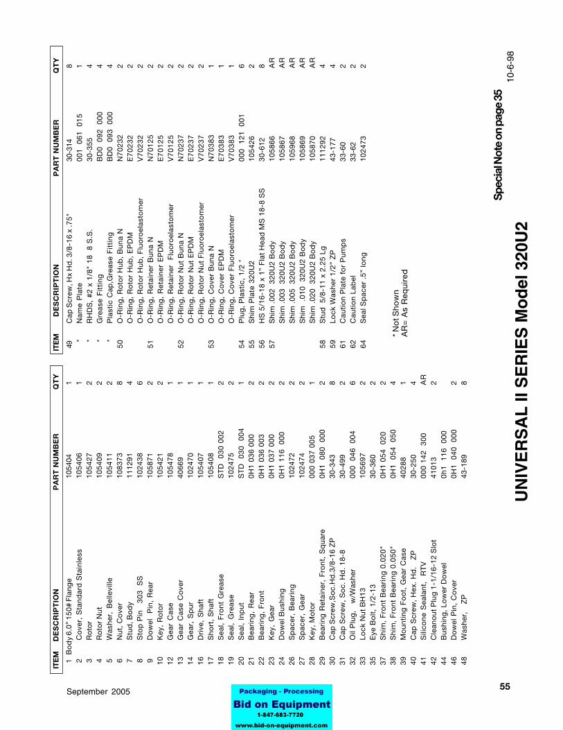
5595-03069September 2005
1B
od
y 6.
0” 1
50#
Fla
nge
1054
041
2C
ove
r, S
tand
ard
Sta
inle
ss10
5406
1 3
Ro
tor
1054
272
4R
oto
r N
ut10
5409
2 5
Was
her,
Bel
levi
lle10
5411
2 6
Nut
, C
ove
r10
8373
8 7
Stu
d, B
od
y11
1291
4 8
Sto
p P
in
303
S
S10
2438
6 9
Do
wel
P
in,
Rea
r10
5871
210
Key
, R
oto
r10
5421
212
Gea
r C
ase
1054
781
13G
ear
Cas
e C
ove
r40
669
114
Gea
r, S
pur
1024
701
16D
rive
, S
haft
1054
071
17S
hort
, S
haft
1054
081
18S
eal,
Fro
nt G
reas
eS
TD
03
0 00
22
19S
eal,
Gre
ase
1024
752
20S
eal,
Inp
utS
TD
03
0 0
041
21B
eari
ng,
Rea
r0H
1 03
6 00
02
22B
eari
ng,
Fro
nt0H
1 03
6 00
32
23K
ey,
Gea
r0H
1 03
7 00
02
24D
ow
el B
ushi
ng0H
1 11
6 0
002
26S
pac
er,
Bea
ring
1024
722
27S
pac
er,
Gea
r10
2474
228
Key
, Mo
tor
000
037
005
129
Bea
ring
Ret
aine
r, F
ront
, S
qua
re0H
1 0
80
000
230
Cap
Scr
ew,S
oc.
Hd
.3/8
-16
ZP
30-3
438
31C
ap S
crew
, S
oc.
Hd
. 18
-830
-499
232
Oil
Plu
g,
w
/Was
her
000
046
00
46
33Lo
ck N
ut B
H13
1056
972
35E
ye B
olt
, 1/
2-13
30-3
602
37S
him
, F
ront
Bea
ring
0.0
20"
0H1
054
020
238
Shi
m,
Fro
nt B
eari
ng 0
.050
"0H
1 0
54
050
439
Mo
unti
ng F
oo
t, G
ear
Cas
e40
288
140
Cap
Scr
ew,
Hex
. H
d.
Z
P30
-250
441
Sili
cone
Sea
lant
, R
TV
000
142
300
AR
42C
lean
out
Plu
g 1
-1/1
6-12
Slo
t41
013
244
Bus
hing
, Lo
wer
Do
wel
0h1
116
00
046
Do
wel
Pin
, C
ove
r0H
1 0
40
000
248
Was
her,
Z
P43
-189
8
ITE
M
DE
SC
RIP
TIO
N
PA
RT
NU
MB
ER
Q
TY
UN
IVE
RS
AL
II S
ER
IES
Mo
del
320
U2
ITE
M
D
ES
CR
IPT
ION
P
AR
T N
UM
BE
R
Q
TY
Spec
ial N
ote
on p
age
35
* N
ot S
how
nA
R=
As
Req
uire
d
49C
ap S
crew
, Hx
Hd
. 3/8
-16
x .7
5"30
-314
8*
Nam
e P
late
001
061
01
51
*R
HD
S,
#2 x
1/8
" 18
8
S.S
.30
-355
4*
Gre
ase
Fit
ting
BD
0 0
92
000
4*
Pla
stic
Cap
,Gre
ase
Fit
ting
BD
0 0
93
000
450
O-R
ing
, R
oto
r H
ub,
Bun
a N
N70
232
2O
-Rin
g,
Ro
tor
Hub
, E
PD
ME
70
23
22
O-R
ing
, R
oto
r H
ub,
Flu
oro
elas
tom
erV
70
23
22
51O
-Rin
g,
Ret
aine
r B
una
NN
7012
52
O-R
ing
, R
etai
ner
EP
DM
E7
01
25
2O
-Rin
g,
Ret
aine
r F
luo
roel
asto
mer
V7
01
25
252
O-R
ing
, R
oto
r N
ut B
una
NN
7023
72
O-R
ing
, R
oto
r N
ut E
PD
ME
70
23
72
O-R
ing
, R
oto
r N
ut F
luo
roel
asto
mer
V7
02
37
253
O-R
ing
, C
ove
r B
una
NN
7038
31
O-R
ing
, C
ove
r E
PD
ME
70
38
31
O-R
ing
, C
ove
r F
luo
roel
asto
mer
V7
03
83
154
Plu
g,
Pla
stic
, 1/
2 "
000
121
00
16
55S
him
Pla
te 3
20U
210
5426
256
HS
5/1
6-18
x 1
” F
lat
Hea
d M
S 1
8-8
SS
30-6
128
57S
him
.00
2 3
20U
2 B
od
y10
5866
AR
Shi
m .
003
320
U2
Bo
dy
1058
67A
RS
him
.00
5 3
20U
2 B
od
y10
5968
AR
Shi
m
.010
32
0U2
Bo
dy
1058
69A
RS
him
.02
0 3
20U
2 B
od
y10
5870
AR
58S
tud
5/8
-11
x 2.
25 L
g11
1292
459
Lock
Was
her
1/2”
ZP
43-1
774
61C
auti
on
Pla
te f
or
Pum
ps
33-6
02
62
Cau
tio
n L
abel
33-6
22
64S
eal S
pac
er .
5” lo
ng10
2473
2
10-6
-98

56 95-03069 September 2005
Item Description Qty. Part No.
1 O-Ring, Inner Buna N 2 N70041
O-Ring, Inner EPDM 2 E70041
O-Ring, Inner Fluoroelastomer 2 V70041
2 O-Ring, Shaft Buna N 2 N70145
O-Ring, Shaft EPDM 2 E70145
O-Ring, Shaft Fluoroelastomer 2 V70145
3 Seal Seat, Ceramic 2 101676
Seal Seat, Silicon Carbide 2 101677
4 Seal Inner, Carbon 2 101663
Seal, Inner, Ceramic 2 101664
Seal, Inner, Tungsten Carbide 2 101666
Seal, Inner, Silicon Carbide 2 101665
5 Wave Spring 2 101689
Item Description Qty. Part No.
1 O-Ring, Inner Buna N 2 N70031
O-Ring, Inner EPDM 2 E70031
O-Ring, Inner Fluoroelastomer 2 V70031
2 O-Ring, Shaft Buna N 2 N70029
O-Ring, Shaft EPDM 2 E70029
O-Ring, Shaft Fluoroelastomer 2 V70029
3 Seal Seat, Ceramic 2 101670
Seal Seat, Silicon Carbide 2 101671
4 Seal Inner, Carbon 2 101655
Seal, Inner, Ceramic 2 101656
Seal, Inner, Tungsten Carbide 2 101658
Seal, Inner, Silicon Carbide 2 101657
5 Wave Spring 2 101685
Item Description Qty. Part No.
1 O-Ring, Inner Buna N 2 N70035
O-Ring, Inner EPDM 2 E70035
O-Ring, Inner Fluoroelastomer 2 V70035
2 O-Ring, Shaft Buna N 2 N70133
O-Ring, Shaft EPDM 2 E70133
O-Ring, Shaft Fluoroelastomer 2 V70133
3 Seal Seat, Ceramic 2 101673
Seal Seat, Silicon Carbide 2 101674
4 Seal Inner, Carbon 2 101659
Seal, Inner, Ceramic 2 101660
Seal, Inner, Tungsten Carbide 2 101662
Seal, Inner, Silicon Carbide 2 101661
5 Wave Spring 2 101687
Item Description Qty. Part No.
1 O-Ring, Inner Buna N 2 N70028
O-Ring, Inner EPDM 2 E70028
O-Ring, Inner Fluoroelastomer 2 V70028
2 O-Ring, Shaft Buna N 2 N70024
O-Ring, Shaft EPDM 2 E70024
O-Ring, Shaft Fluoroelastomer 2 V70024
3 Seal Seat, Ceramic 2 101667
Seal Seat, Silicon Carbide 2 101668
4 Seal Inner, Carbon 2 101651
Seal, Inner, Ceramic 2 101652
Seal, Inner, Tungsten Carbide 2 101654
Seal, Inner, Silicon Carbide 2 101653
5 Wave Spring 2 101683
WAUKESHA UNIVERSAL II PUMP
STANDARD SINGLE MECHANICAL SEAL(INNER)
Model 006U2-015U2-018U2
Model 030U2 Model 180U2 - 220U2
Model 045U2 - 060U2 - 130U2
(Quantities are per pump) 5-4-98
2
1
4
5
3
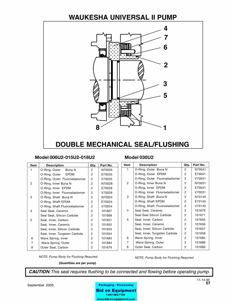
5795-03069September 2005
Item Description Qty. Part No.
1 O-Ring, Outer Buna N 2 N70041
O-Ring, Outer EPDM 2 E70041
O-Ring, Outer Fluoroelastomer 2 V70041
2 O-Ring, Inner Buna N 2 N70031
O-Ring, Inner EPDM 2 E70031
O-Ring, Inner Fluoroelastomer 2 V70031
3 O-Ring, Shaft Buna N 2 N70145
O-Ring, Shaft EPDM 2 E70145
O-Ring, Shaft Fluoroelastomer 2 V70145
4 Seal Seat, Ceramic 2 101670
Seal Seal Silicon Carbide 2 101671
5 Seal, Inner, Carbon 2 101655
Seal, Inner, Ceramic 2 101656
Seal, Inner, Silicon Carbide 2 101657
Seal, Inner, Tungsten Carbide 2 101658
6 Wave Spring, Inner 2 101685
7 Wave Spring, Outer 2 101686
8 Outer Seal, Carbon 2 101680
Item Description Qty. Part No.
1 O-Ring, Outer Buna N 2 N70035
O-Ring, Outer EPDM 2 E70035
O-Ring, Outer Fluoroelastomer 2 V70035
2 O-Ring, Inner Buna N 2 N70028
O-Ring, Inner EPDM 2 E70028
O-Ring, Inner Fluoroelastomer 2 V70028
3 O-Ring, Shaft Buna N 2 N70024
O-Ring, Shaft EPDM 2 E70024
O-Ring, Shaft Fluoroelastomer 2 V70024
4 Seal Seat, Ceramic 2 101667
Seal Seat, Silicon Carbide 2 101668
5 Seal, Inner, Carbon 2 101651
Seal, Inner, Ceramic 2 101652
Seal, Inner, Silicon Carbide 2 101653
Seal, Inner, Tungsten Carbide 2 101654
6 Wave Spring, Inner 2 101683
7 Wave Spring, Outer 2 101684
8 Outer Seal, Carbon 2 101679
WAUKESHA UNIVERSAL II PUMP
DOUBLE MECHANICAL SEAL/FLUSHING
Model 006U2-015U2-018U2 Model 030U2
CAUTION:This seal requires flushing to be connected and flowing before operating pump.
4
6
1
5
2
3
8
7
NOTE: Pump Body for Flushing RequiredNOTE: Pump Body for Flushing Required
(Quantities are per pump)
11-14-96

58 95-03069 September 2005
Item Description Qty. Part No.
1 O-Ring, Outer Buna N 2 N70046
O-Ring, Outer EPDM 2 E70046
O-Ring, Outer Fluoroelastomer 2 V70046
2 O-Ring, Inner Buna N 2 N70041
O-Ring, Inner EPDM 2 E70041
O-Ring, Inner Fluoroelastomer 2 V70041
3 O-Ring, Shaft Buna N 2 N70145
O-Ring, Shaft EPDM 2 E70145
O-Ring, Shaft Fluoroelastomer 2 V70145
4 Seal Seat, Ceramic 2 101676
Seal Seal Silicon Carbide 2 101677
5 Seal, Inner, Carbon 2 101663
Seal, Inner, Ceramic 2 101664
Seal, Inner, Silicon Carbide 2 101665
Seal, Inner, Tungsten Carbide 2 101666
6 Wave Spring, Inner 2 101689
7 Wave Spring, Outer 2 101690
8 Outer Seal, Carbon 2 101682
Item Description Qty. Part No.
1 O-Ring, Outer Buna N 2 N70043
O-Ring, Outer EPDM 2 E70043
O-Ring, Outer Fluoroelastomer 2 V70043
2 O-Ring, Inner Buna N 2 N70035
O-Ring, Inner EPDM 2 E70035
O-Ring, Inner Fluoroelastomer 2 V70035
3 O-Ring, Shaft Buna N 2 N70133
O-Ring, Shaft EPDM 2 E70133
O-Ring, Shaft Fluoroelastomer 2 V70133
4 Seal Seat, Ceramic 2 101673
Seal Seal Silicon Carbide 2 101674
5 Seal, Inner, Carbon 2 101659
Seal, Inner, Ceramic 2 101660
Seal, Inner, Silicon Carbide 2 101661
Seal, Inner, Tungsten Carbide 2 101662
6 Wave Spring, Inner 2 101687
7 Wave Spring, Outer 2 101688
8 Outer Seal, Carbon 2 101681
WAUKESHA UNIVERSAL II PUMP
CAUTION:This seal requires flushing to be connected and flowing before operating pump.
DOUBLE MECHANICAL SEAL/FLUSHINGModel 045U2 - 060U2 - 130U2 Model 180U2 - 220U2
NOTE: Use Flushing Pump Body
(Quantities are per pump)
5-4-98
6 74
18
5
3
2

5995-03069September 2005
Item Description Qty. Part No.
1 O-Ring, Outer Buna N 2 N70160
O-Ring, Outer EPDM 2 E70160
O-Ring, Outer Fluoroelastomer 2 V70160
2 O-Ring, Inner Buna N 2 N70154
O-Ring, Inner EPDM 2 E70154
O-Ring, Inner Fluoroelastomer 2 V70154
3 O-Ring, Shaft Buna N 2 N70148
O-Ring, Shaft EPDM 2 E70148
O-Ring, Shaft Fluoroelastomer 2 V70148
4 Seal Seat, Ceramic 2 105416
5 Seal, Inner, Carbon 2 105412
Seal, Inner, Ceramic 2 105413
6 Wave Spring, Inner 2 105419
7 Wave Spring, Outer 2 105420
8 Outer Seal, Carbon 2 105418
6
74
18
53
21
4
53
2
Model 320U2
DOUBLE MECHANICAL SEALSINGLE MECHANICAL SEAL
Item Description Qty. Part No.
1 O-Ring, Inner Buna N 2 N70154
O-Ring, Inner EPDM 2 E70154
O-Ring, Inner Fluoroelastomer 2 V70154
2 O-Ring, Shaft Buna N 2 N70148
O-Ring, Shaft EPDM 2 E70148
O-Ring, Shaft Fluoroelastomer 2 V70148
3 Seal Seat, Ceramic 2 105416
Seal Seat, Silicon Carbide 2 105417
4 Seal Inner, Carbon 2 105412
Seal, Inner, Ceramic 2 105413
5 Wave Spring, Inner 2 105419
WAUKESHA UNIVERSAL II PUMP
8-28-98
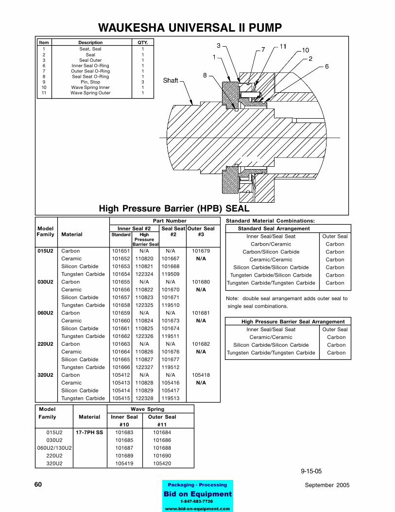
60 95-03069 September 2005
WAUKESHA UNIVERSAL II PUMP
9-15-05
Part Number
Model Inner Seal #2 Seal Seat Outer SealFamily Material Standard High #2 #3
Pressure Barrier Seal
015U2 Carbon 101651 N/A N/A 101679
Ceramic 101652 110820 101667 N/A
Silicon Carbide 101653 110821 101668
Tungsten Carbide 101654 122324 119509
030U2 Carbon 101655 N/A N/A 101680
Ceramic 101656 110822 101670 N/A
Silicon Carbide 101657 110823 101671
Tungsten Carbide 101658 122325 119510
060U2 Carbon 101659 N/A N/A 101681
Ceramic 101660 110824 101673 N/A
Silicon Carbide 101661 110825 101674
Tungsten Carbide 101662 122326 119511
220U2 Carbon 101663 N/A N/A 101682
Ceramic 101664 110826 101676 N/A
Silicon Carbide 101665 110827 101677
Tungsten Carbide 101666 122327 119512
320U2 Carbon 105412 N/A N/A 105418
Ceramic 105413 110828 105416 N/A
Silicon Carbide 105414 110829 105417
Tungsten Carbide 105415 122328 119513
Model Wave Spring
Family Material Inner Seal Outer Seal
#10 #11
015U2 17-7PH SS 101683 101684
030U2 101685 101686
060U2/130U2 101687 101688
220U2 101689 101690
320U2 105419 105420
Standard Material Combinations:
Standard Seal Arrangement
Inner Seal/Seal Seat Outer Seal
Carbon/Ceramic Carbon
Carbon/Silicon Carbide Carbon
Ceramic/Ceramic Carbon
Silicon Carbide/Silicon Carbide Carbon
Tungsten Carbide/Silicon Carbide Carbon
Tungsten Carbide/Tungsten Carbide Carbon
Note: double seal arrangemant adds outer seal to
single seal combinations.
High Pressure Barrier Seal Arrangement
Inner Seal/Seal Seat Outer Seal
Ceramic/Ceramic Carbon
Silicon Carbide/Silicon Carbide Carbon
Tungsten Carbide/Tungsten Carbide Carbon
High Pressure Barrier (HPB) SEAL
Item Description QTY.1 Seat, Seal 12 Seal 13 Seal Outer 16 Inner Seal O-Ring 17 Outer Seal O-Ring 18 Seal Seat O-Ring 19 Pin, Stop 310 Wave Spring Inner 111 Wave Spring Outer 1
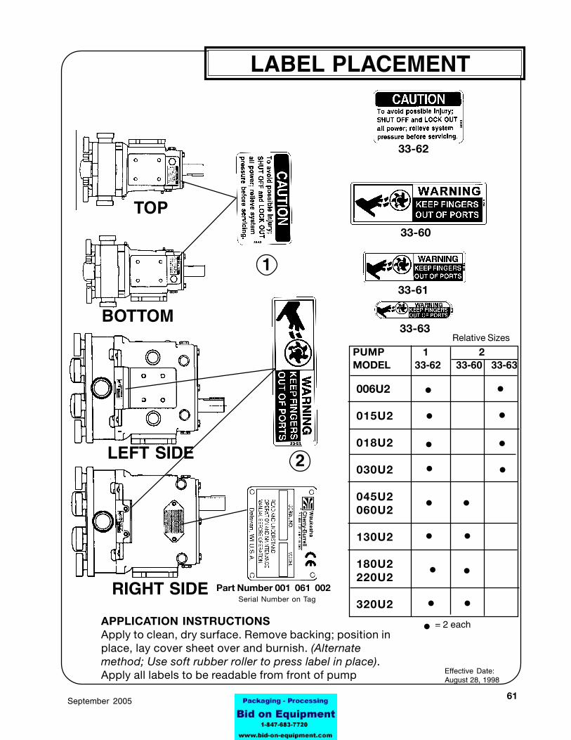
6195-03069September 2005
LEFT SIDE
RIGHT SIDE
BOTTOM
TOP
Part Number 001 061 002
Relative Sizes
APPLICATION INSTRUCTIONSApply to clean, dry surface. Remove backing; position inplace, lay cover sheet over and burnish. (Alternatemethod; Use soft rubber roller to press label in place).Apply all labels to be readable from front of pump
33-62
33-60
33-61
33-63
LABEL PLACEMENT
Effective Date:August 28, 1998
1
PUMP 1 2MODEL 33-62 33-60 33-63
Serial Number on Tag
2
•006U2
015U2
018U2
030U2
045U2060U2
130U2
180U2220U2
320U2
•••
•
•••
•••
•
••
= 2 each•
••