Embed Size (px)
Citation preview
• www.maxlinear.com • 057-W2PLHNPUGR01
Wave-2 Powerline Networking Evaluation
Public User Guide

Wave-2 Powerline Networking Evaluation Public User Guide Revision History
www.maxlinear.comOctober 18, 2018 057-W2PLHNPUGR01 ii
Revision HistoryDocument No. Release Date Change Description057-W2PLHNPUGR01 October 18, 2018 Updated:
■ New template applied.■ Minor edits so that the document applies to home networking or industrial
applications.
057-W2PLHNPUGR00 March 13, 2018 Initial release.
Wave-2 Powerline Networking Evaluation Public User Guide Table of Contents
www.maxlinear.comOctober 18, 2018 057-W2PLHNPUGR01 iii
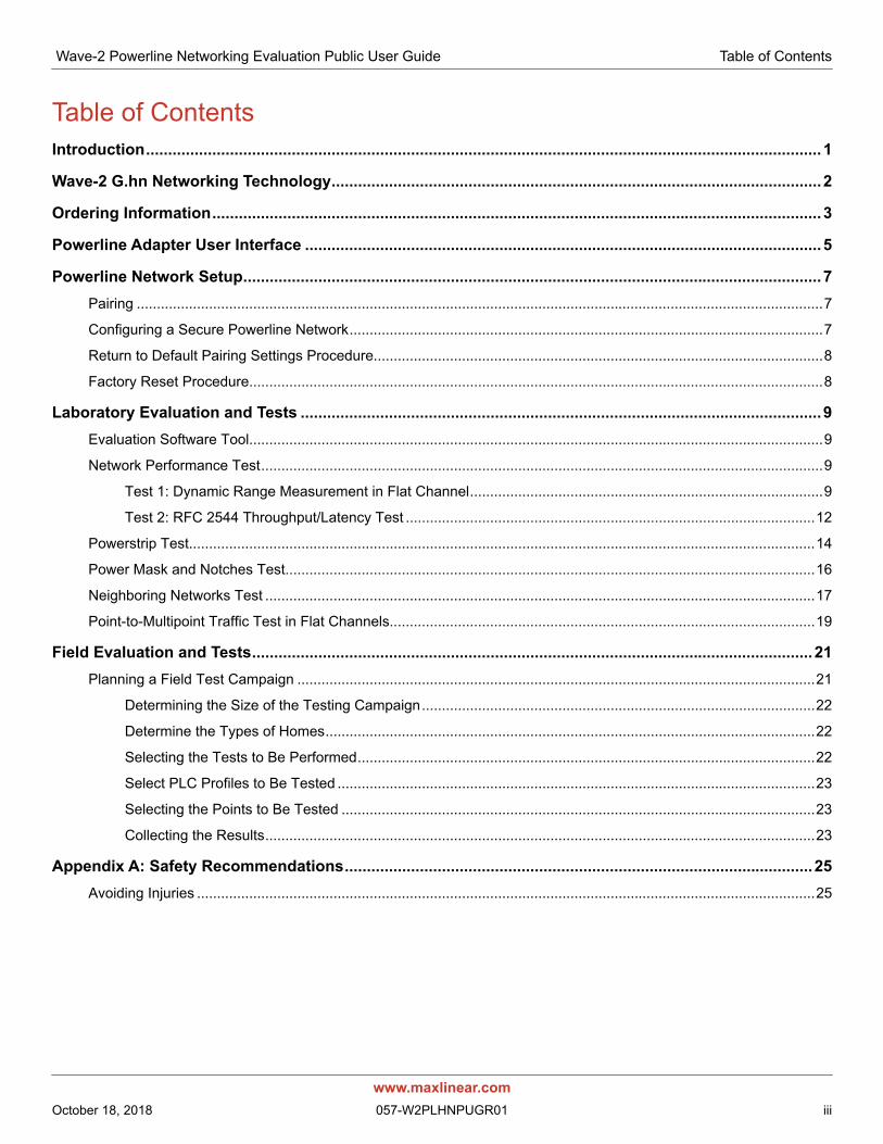
Table of ContentsIntroduction......................................................................................................................................................... 1
Wave-2 G.hn Networking Technology...............................................................................................................2
Ordering Information..........................................................................................................................................3
Powerline Adapter User Interface .....................................................................................................................5
Powerline Network Setup...................................................................................................................................7Pairing ...........................................................................................................................................................................7
Configuring a Secure Powerline Network......................................................................................................................7
Return to Default Pairing Settings Procedure................................................................................................................8
Factory Reset Procedure...............................................................................................................................................8
Laboratory Evaluation and Tests ......................................................................................................................9Evaluation Software Tool...............................................................................................................................................9
Network Performance Test............................................................................................................................................9
Test 1: Dynamic Range Measurement in Flat Channel........................................................................................9
Test 2: RFC 2544 Throughput/Latency Test ......................................................................................................12
Powerstrip Test............................................................................................................................................................14
Power Mask and Notches Test....................................................................................................................................16
Neighboring Networks Test .........................................................................................................................................17
Point-to-Multipoint Traffic Test in Flat Channels..........................................................................................................19
Field Evaluation and Tests...............................................................................................................................21Planning a Field Test Campaign .................................................................................................................................21
Determining the Size of the Testing Campaign..................................................................................................22
Determine the Types of Homes..........................................................................................................................22
Selecting the Tests to Be Performed..................................................................................................................22
Select PLC Profiles to Be Tested .......................................................................................................................23
Selecting the Points to Be Tested ......................................................................................................................23
Collecting the Results.........................................................................................................................................23
Appendix A: Safety Recommendations..........................................................................................................25Avoiding Injuries ..........................................................................................................................................................25
Wave-2 Powerline Networking Evaluation Public User Guide List of Tables
www.maxlinear.comOctober 18, 2018 057-W2PLHNPUGR01 iv
List of TablesTable 1: Wave-2 PLC Networking Ordering Information ......................................................................................3
Table 2: Ordering Information for Telebyte’s UPLC Splitters................................................................................4
Table 3: DW920 Connectors and Button ..............................................................................................................5
Table 4: Link Quality Indicator Description ...........................................................................................................6
Table 5: Secure Indicator Description...................................................................................................................6
Table 6: CONFIG Button ......................................................................................................................................6
Table 7: DW920 Iperf UDP Measurements (Mbps)–PLC MIMO 100 MHz Boost 2 ˟ 2 Profile ...........................11
Table 8: DW920 Iperf TCP Measurements (Mbps)–PLC MIMO 100 MHz Boost 2 ˟ 2 Profile............................11
Table 9: DW920 UDP Unidirectional Measurements (Mbps)–PLC MIMO 100 MHz Boost 2 ˟ 2 Profile.............13
Table 10: DW920 UDP Bidirectional Measurements (Mbps)–PLC MIMO 100 MHz Boost 2 ˟ 2 Profile.............13
Table 11: PLC 100 MHz MIMO Boost 2 ˟ 2–DW920 Ixia RF2544 PLR 0% MAC xput Test Results for Same Powerstrip ..........................................................................................................................................15
Table 12: Results RFC 2889 Fully Meshed Test PLR 0% Bidirectional .............................................................20
Table 13: Example of General Field Test Information ........................................................................................23
Table 14: Example of Outlet Description ............................................................................................................24
Table 15: Example of Outlets Description ..........................................................................................................24
Wave-2 Powerline Networking Evaluation Public User Guide List of Figures
www.maxlinear.comOctober 18, 2018 057-W2PLHNPUGR01 v
List of FiguresFigure 1: Wave-2 DW920 GbE to Powerline Adapter Block Diagram ..................................................................2
Figure 2: Wave-2 DW920 Gigabit Ethernet to Powerline Adapter........................................................................3
Figure 3: Universal PLC Signal Splitter ................................................................................................................4
Figure 4: Pairing Procedure in MaxLinear Powerline Adapter..............................................................................7
Figure 5: Test Setup for 2 PLC Adapters Based on TR208................................................................................10
Figure 6: Test Setup with Powerstrip..................................................................................................................14
Figure 7: Notching Test ......................................................................................................................................16
Figure 8: Neighboring Networks Test Set Up Based on TR208 .........................................................................17
Figure 9: Test Diagrams for Point to Multipoint ..................................................................................................19

Wave-2 Powerline Networking Evaluation Public User Guide Introduction
IntroductionThe scope of this document is to provide a guide for evaluating MaxLinear’s G.hn Wave-2 Powerline Communications (PLC) solution for home networking or industrial applications. The features described and performance data within this document are for guidance only, and they cannot be construed as any form of specification, guarantee, or contract between MaxLinear and the evaluator.
This user guide helps engineers to evaluate powerline networking solution feature set at technical level using hardware and software tools provided in evaluation package, and to learn about the technology at the same time as checking its real world performance.
Before continuing read carefully the “Appendix A: Safety Recommendations” on page 25.
Warning! The electrical safety of this Evaluation Kit (EVK) has not been fully evaluated against the requirements of the EN 60950-1:2006 (IEC 60950-1:2005) standard and this EVK does not fulfill with all the relevant electrical safety requirements stated in such standard.
www.maxlinear.comOctober 18, 2018 057-W2PLHNPUGR01 1
Wave-2 Powerline Networking Evaluation Public User Guide Wave-2 G.hn Networking Technology
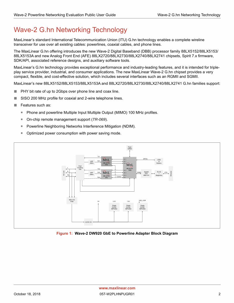
Wave-2 G.hn Networking TechnologyMaxLinear’s standard International Telecommunication Union (ITU) G.hn technology enables a complete wireline transceiver for use over all existing cables: powerlines, coaxial cables, and phone lines.
The MaxLinear G.hn offering introduces the new Wave-2 Digital Baseband (DBB) processor family 88LX5152/88LX5153/88LX5153A and new Analog Front End (AFE) 88LX2720/88LX2730/88LX2740/88LX2741 chipsets, Spirit 7.x firmware, SDK/API, associated reference designs, and auxiliary software tools.
MaxLinear’s G.hn technology provides exceptional performance and industry-leading features, and it is intended for triple-play service provider, industrial, and consumer applications. The new MaxLinear Wave-2 G.hn chipset provides a very compact, flexible, and cost-effective solution, which includes several interfaces such as an RGMII and SGMII.
MaxLinear’s new 88LX5152/88LX5153/88LX5153A and 88LX2720/88LX2730/88LX2740/88LX2741 G.hn families support:
■ PHY bit rate of up to 2Gbps over phone line and coax line.
■ SISO 200 MHz profile for coaxial and 2-wire telephone lines.
■ Features such as:
Phone and powerline Multiple Input Multiple Output (MIMO) 100 MHz profiles.
On-chip remote management support (TR-069).
Powerline Neighboring Networks Interference Mitigation (NDIM).
Optimized power consumption with power saving mode.
Figure 1: Wave-2 DW920 GbE to Powerline Adapter Block Diagram
Dual Coupling
Unit
ISN & AC Filter
88LX2720 AFE
88LX2720 AFE
88LX5152 DBB
AC/DC 5V
Single DC/DC
88PG852
Single DC/DC
88PG852
Single DC/DC
88PG852
GigabitPHY
88E1514
RJ-45+
Magnetics
LEDs&
Buttons
Eth
erne
t
AC
Lin
e
HPF 2MHz
HPF 2MHz
Flash32Mbit
L
N
PE
Tx1
Tx2
Rx1
Rx2
Rx3
5V 3.3V 1.5V VDD_CORE
Control
SGMII
GPIOs
ETH
DAC 1
ADC 1
ADC 2
DAC 2
ADC 3
ADC 4
SPI1
www.maxlinear.comOctober 18, 2018 057-W2PLHNPUGR01 2
Wave-2 Powerline Networking Evaluation Public User Guide Ordering Information
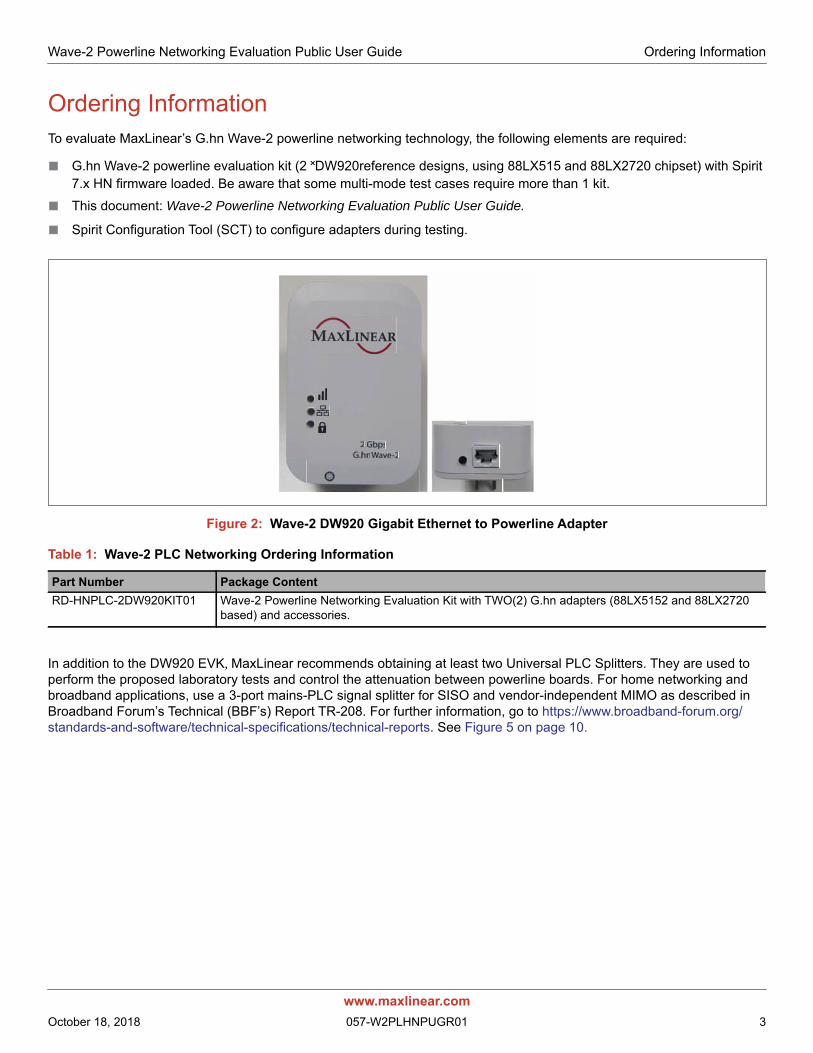
Ordering InformationTo evaluate MaxLinear’s G.hn Wave-2 powerline networking technology, the following elements are required:
■ G.hn Wave-2 powerline evaluation kit (2 ˟DW920reference designs, using 88LX515 and 88LX2720 chipset) with Spirit 7.x HN firmware loaded. Be aware that some multi-mode test cases require more than 1 kit.
■ This document: Wave-2 Powerline Networking Evaluation Public User Guide.
■ Spirit Configuration Tool (SCT) to configure adapters during testing.
Figure 2: Wave-2 DW920 Gigabit Ethernet to Powerline Adapter
In addition to the DW920 EVK, MaxLinear recommends obtaining at least two Universal PLC Splitters. They are used to perform the proposed laboratory tests and control the attenuation between powerline boards. For home networking and broadband applications, use a 3-port mains-PLC signal splitter for SISO and vendor-independent MIMO as described in Broadband Forum’s Technical (BBF’s) Report TR-208. For further information, go to https://www.broadband-forum.org/standards-and-software/technical-specifications/technical-reports. See Figure 5 on page 10.
Table 1: Wave-2 PLC Networking Ordering Information
Part Number Package ContentRD-HNPLC-2DW920KIT01 Wave-2 Powerline Networking Evaluation Kit with TWO(2) G.hn adapters (88LX5152 and 88LX2720
based) and accessories.
www.maxlinear.comOctober 18, 2018 057-W2PLHNPUGR01 3
Wave-2 Powerline Networking Evaluation Public User Guide Ordering Information
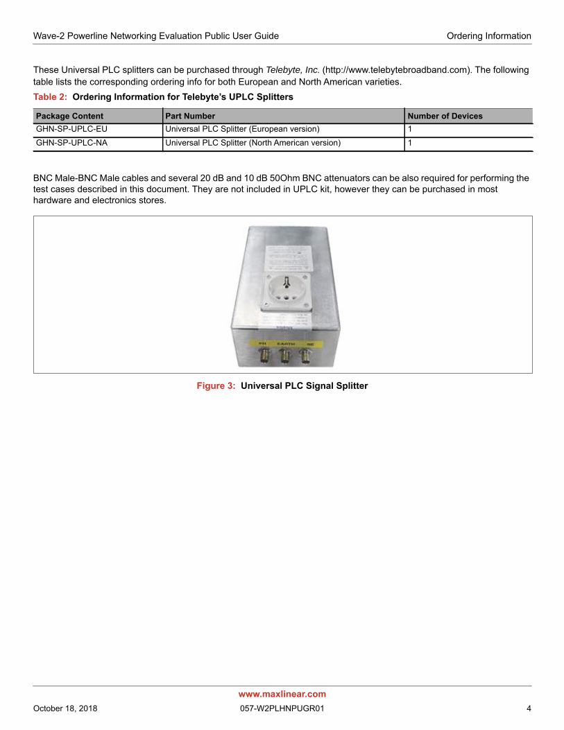
These Universal PLC splitters can be purchased through Telebyte, Inc. (http://www.telebytebroadband.com). The following table lists the corresponding ordering info for both European and North American varieties.
BNC Male-BNC Male cables and several 20 dB and 10 dB 50Ohm BNC attenuators can be also required for performing the test cases described in this document. They are not included in UPLC kit, however they can be purchased in most hardware and electronics stores.
Figure 3: Universal PLC Signal Splitter
Table 2: Ordering Information for Telebyte’s UPLC Splitters
Package Content Part Number Number of DevicesGHN-SP-UPLC-EU Universal PLC Splitter (European version) 1
GHN-SP-UPLC-NA Universal PLC Splitter (North American version) 1
www.maxlinear.comOctober 18, 2018 057-W2PLHNPUGR01 4
Wave-2 Powerline Networking Evaluation Public User Guide Powerline Adapter User Interface
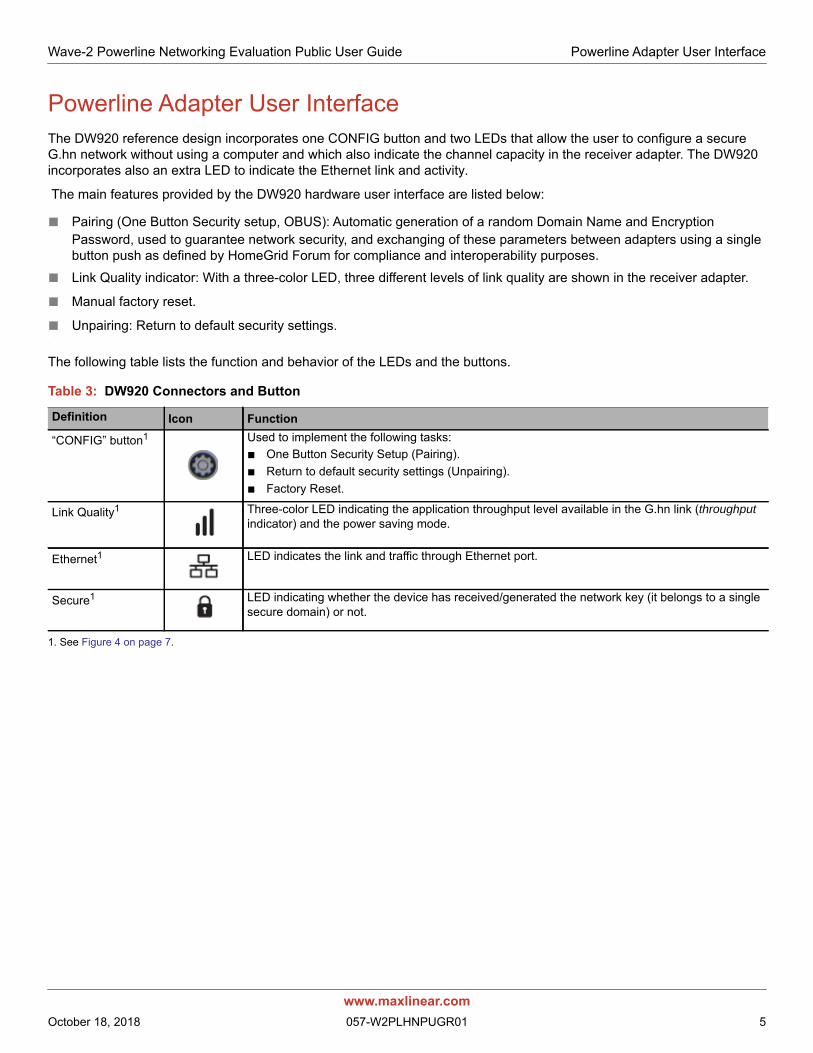
Powerline Adapter User InterfaceThe DW920 reference design incorporates one CONFIG button and two LEDs that allow the user to configure a secure G.hn network without using a computer and which also indicate the channel capacity in the receiver adapter. The DW920 incorporates also an extra LED to indicate the Ethernet link and activity.
The main features provided by the DW920 hardware user interface are listed below:
■ Pairing (One Button Security setup, OBUS): Automatic generation of a random Domain Name and Encryption Password, used to guarantee network security, and exchanging of these parameters between adapters using a single button push as defined by HomeGrid Forum for compliance and interoperability purposes.
■ Link Quality indicator: With a three-color LED, three different levels of link quality are shown in the receiver adapter.
■ Manual factory reset.
■ Unpairing: Return to default security settings..
The following table lists the function and behavior of the LEDs and the buttons.
1. See Figure 4 on page 7.
Table 3: DW920 Connectors and Button
Definition Icon Function
“CONFIG” button1 Used to implement the following tasks:■ One Button Security Setup (Pairing).■ Return to default security settings (Unpairing).■ Factory Reset.
Link Quality1 Three-color LED indicating the application throughput level available in the G.hn link (throughput indicator) and the power saving mode.
Ethernet1 LED indicates the link and traffic through Ethernet port.
Secure1 LED indicating whether the device has received/generated the network key (it belongs to a single secure domain) or not.
www.maxlinear.comOctober 18, 2018 057-W2PLHNPUGR01 5
Wave-2 Powerline Networking Evaluation Public User Guide Powerline Adapter User Interface
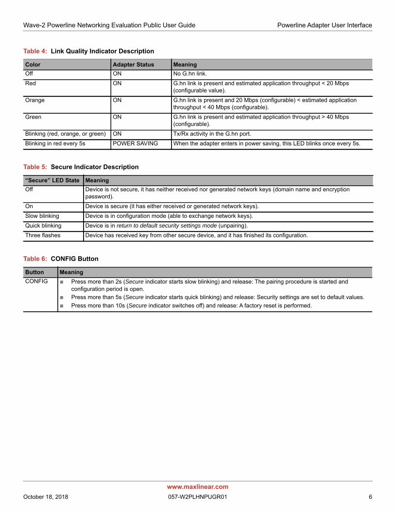
Table 4: Link Quality Indicator Description
Color Adapter Status MeaningOff ON No G.hn link.
Red ON G.hn link is present and estimated application throughput < 20 Mbps (configurable value).
Orange ON G.hn link is present and 20 Mbps (configurable) < estimated application throughput < 40 Mbps (configurable).
Green ON G.hn link is present and estimated application throughput > 40 Mbps (configurable).
Blinking (red, orange, or green) ON Tx/Rx activity in the G.hn port.
Blinking in red every 5s POWER SAVING When the adapter enters in power saving, this LED blinks once every 5s.
Table 5: Secure Indicator Description
“Secure” LED State MeaningOff Device is not secure, it has neither received nor generated network keys (domain name and encryption
password).
On Device is secure (it has either received or generated network keys).
Slow blinking Device is in configuration mode (able to exchange network keys).
Quick blinking Device is in return to default security settings mode (unpairing).
Three flashes Device has received key from other secure device, and it has finished its configuration.
Table 6: CONFIG Button
Button MeaningCONFIG ■ Press more than 2s (Secure indicator starts slow blinking) and release: The pairing procedure is started and
configuration period is open.■ Press more than 5s (Secure indicator starts quick blinking) and release: Security settings are set to default values.■ Press more than 10s (Secure indicator switches off) and release: A factory reset is performed.
www.maxlinear.comOctober 18, 2018 057-W2PLHNPUGR01 6
Wave-2 Powerline Networking Evaluation Public User Guide Powerline Network Setup
Powerline Network Setup
PairingAll MaxLinear G.hn adapters have the same not unique domain name and AES encryption password by default. As a result, when they are plugged into the physical medium (PLC, coax, or phone line), a new network is created which operates smoothly, but without a secure unique configuration.
Any nearby G.hn adapter (wanted or unwanted) with same common domain name and AES encryption password connected to the same electrical grid becomes part of this G.hn network. MaxLinear recommends to configure a private G.hn network (with a unique domain name and AES encryption password) to guarantee the security of every user’s network.
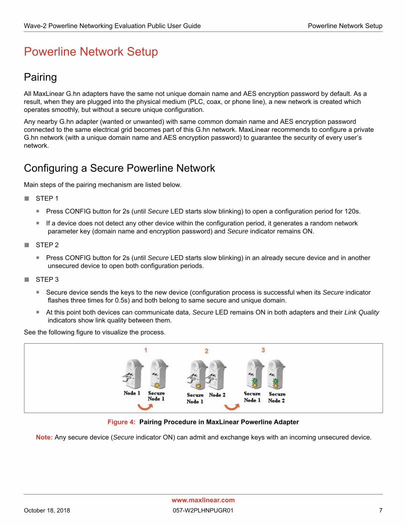
Configuring a Secure Powerline NetworkMain steps of the pairing mechanism are listed below.
■ STEP 1
Press CONFIG button for 2s (until Secure LED starts slow blinking) to open a configuration period for 120s.
If a device does not detect any other device within the configuration period, it generates a random network parameter key (domain name and encryption password) and Secure indicator remains ON.
■ STEP 2
Press CONFIG button for 2s (until Secure LED starts slow blinking) in an already secure device and in another unsecured device to open both configuration periods.
■ STEP 3
Secure device sends the keys to the new device (configuration process is successful when its Secure indicator flashes three times for 0.5s) and both belong to same secure and unique domain.
At this point both devices can communicate data, Secure LED remains ON in both adapters and their Link Quality indicators show link quality between them.
See the following figure to visualize the process.
Figure 4: Pairing Procedure in MaxLinear Powerline Adapter
Note: Any secure device (Secure indicator ON) can admit and exchange keys with an incoming unsecured device.
www.maxlinear.comOctober 18, 2018 057-W2PLHNPUGR01 7
Wave-2 Powerline Networking Evaluation Public User Guide Return to Default Pairing Settings Procedure
Return to Default Pairing Settings ProcedureThe Return to Default Pairing Settings procedure forces a G.hn adapter to return to its default security settings. This procedure only resets the following parameters (domain name and AES encryption password) and does not affect other parameters such as (IP configuration, G.hn profile, notches, etc.).
Perform the following steps to do it:
1. Press “CONFIG” button for more than 5s (Secure indicator should start slow blinking and after 5s starts quick blinking). Release the button.
2. At this time, the adapter resets its running security configuration to the default settings (unpaired).
Factory Reset ProcedureThe Factory Reset procedure forces a G.hn adapter to return to its factory security settings. This procedure resets all parameters stored in flash memory, including (IP configuration, G.hn profile, security settings, notches, log file, QoS, Ethernet powers saving, etc).
Perform the following steps to do it.
1. Press CONFIG button (Secure indicator should start slow blinking and after 5s quick blinking) and DO NOT release it until the Secure indicator switches OFF (it takes around 10s). Release the button.
2. After a few seconds the Link Quality indicator is also OFF.
3. At this time, the adapter resets its running configuration to factory default settings and auto-reboots
www.maxlinear.comOctober 18, 2018 057-W2PLHNPUGR01 8
Wave-2 Powerline Networking Evaluation Public User Guide Laboratory Evaluation and Tests
Laboratory Evaluation and Tests
Evaluation Software ToolThe SCT is a Java software tool to help evaluators during their testing of G.hn adapters.
SCT enables reading and writing main configuration settings of MaxLinear G.hn adapters belonging to same logical network and it is used for most of the evaluation tests introduced in this section.
For more information about installation and use of SCT refer to document Spirit Configuration Tool (SCT) Public User Guide (052SCTPUG).
Network Performance Test
Test 1: Dynamic Range Measurement in Flat ChannelThis test concentrates on network performance. The evaluator can measure the variation of the following variables as a function of attenuation.
■ Physical throughput
■ TCP throughput
■ UDP throughput
Test Equipment
■ 2 ˟ MaxLinear DW920adapters
■ A dedicated network performance analysis system such as Ixia or Spirent's Smartbits
■ Alternatively, use two PCs with one of the following software options:
Chariot SW from Ixia.
Iperf software (a public domain application that can be downloaded for free), but the specific hardware and operating system could place a limitation on the results. I.e., Windows PC usually limits iperf UDP performance as client, so Linux (or Mac OS)is recommended for UDP performance tests when possible.
PCATTCP software (a public domain application that can be downloaded for free) which can be used on Linux and Windows PCs for both TCP and UDP measurements. It is available at http://www.pcausa.com/Utilities/pcattcp.htm.
■ SCT
■ 2 ˟ GHN-SP-UPLC
■ 3 ˟ BNC coax cables
■ Combined fixed attenuators
Figure 5 on page 10 shows the test setup diagram using mentioned test equipment.
Note: DW920 devices included in EVK are configured by default in PLC 100 MHz MIMO Boost 2˟2 profile. This mode has an improved PSD over 30 MHz. This PSD levels are equivalent to the ones used currently in commercial equipment across all different legacy powerline technologies.
www.maxlinear.comOctober 18, 2018 057-W2PLHNPUGR01 9
Wave-2 Powerline Networking Evaluation Public User Guide Network Performance Test
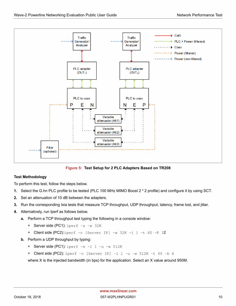
Figure 5: Test Setup for 2 PLC Adapters Based on TR208
Test Methodology
To perform this test, follow the steps below.
1. Select the G.hn PLC profile to be tested (PLC 100 MHz MIMO Boost 2 ˟ 2 profile) and configure it by using SCT.
2. Set an attenuation of 10 dB between the adapters.
3. Run the corresponding Ixia tests that measure TCP throughput, UDP throughput, latency, frame lost, and jitter.
4. Alternatively, run Iperf as follows below.
a. Perform a TCP throughput test typing the following in a console window:
Server side (PC1): iperf –s –w 32K
Client side (PC2):iperf –c [Server IP] –w 32K –i 1 –t 60 –P 32
b. Perform a UDP throughput by typing:
Server side (PC1): iperf -s –i 1 –u –w 512K
Client side (PC2): iperf -c [Server IP] -i 1 –u –w 512K -t 60 -b X
where X is the injected bandwidth (in bps) for the application. Select an X value around 950M.
www.maxlinear.comOctober 18, 2018 057-W2PLHNPUGR01 10

Wave-2 Powerline Networking Evaluation Public User Guide Network Performance Test
5. Alternatively, run PCATTCP as follows:
a. Perform a TCP throughput test typing the following commands in a console window:
Server side (PC1): PCATTCP.exe -r –c -f m -b 512000
Client side (PC2): PCATTCP.exe -t -f m –u -n 300000 <server IP>
b. Perform a UDP throughput test by typing:
Server side (PC1): PCATTCP.exe -r –c –f m –u
Client side (PC2): PCATTCP.exe -t -f m –u -n 300000 <server IP>
6. Optional: Write down the transmission and reception physical throughput obtained using SCT.
7. Repeat steps 3 to 6 increasing the attenuation value by 10 dB or 20 dB until achieved throughput is near to 0.
8. Write down the results in a table similar to the following table.
Note: The following results were obtained using Spirit 7.6 HN GA version (SPIRIT.v7_6_r548+8) loaded..
Table 7: DW920 Iperf UDP Measurements (Mbps)–PLC MIMO 100 MHz Boost 2 ˟ 2 Profile
Attenuation PLC 100 MHz MIMO Boost 2˟210 dB 933
20 dB 933
30 dB 933
40 dB 903
50 dB 821
60 dB 587
70 dB 346
75 dB 230
80 dB 157
85 dB 81
90 dB 39
95 dB 16
100 dB 0
Table 8: DW920 Iperf TCP Measurements (Mbps)–PLC MIMO 100 MHz Boost 2 ˟ 2 Profile
Attenuation PLC 100 MHz MIMO Boost 2˟210 dB 765
20 dB 764
30 dB 756
40 dB 725
50 dB 631
60 dB 447
70 dB 260
80 dB 87.9
90 dB 25
www.maxlinear.comOctober 18, 2018 057-W2PLHNPUGR01 11

Wave-2 Powerline Networking Evaluation Public User Guide Network Performance Test
Test 2: RFC 2544 Throughput/Latency TestThe RFC 2544 methodology, established by the Internet Engineering Task Force (IETF), is the de-facto methodology that outlines the tests required to measure and prove performance criteria for carrier Ethernet networks. The standard provides an out-of-service benchmarking methodology to evaluate the performance of network devices using throughput, frame loss, and latency tests.
The methodology defines the frame size, test duration, and number of test iterations. Once completed, these tests provide performance metrics of the Ethernet network under test.
To ensure that an Ethernet network is capable of supporting a variety of services (such as VoIP or video), the RFC 2544 test suite supports seven pre-defined frame sizes (64, 128, 256, 512, 1024, 1280, and 1518 bytes) to simulate various traffic conditions. Small frame sizes increase the number of frames transmitted, thereby stressing the network device as it must switch a large number of frames.
The test starts by sending frames at the specified rate (usually the maximum theoretical rate of the port), while the frame loss is monitored. Frames are sent from and received at all the ports on the device under test, and the Tx and Rx rates are recorded. A binary, step, or combo search algorithm is used to identify the maximum rate at which no frame loss is experienced.
The latency test determines the latency of the device under test. In the latency test, frames are transmitted for a fixed duration. Rx ports compute the latency values for every frame in the test by comparing the Tx timestamp with the Rx timestamp. The difference between the two timestamps is the latency. This quick test provides the statistical results: Average latency, minimum latency, and maximum latency.
Test Equipment
■ 2 ˟ MaxLinear DW920 adaptersA dedicated network performance analysis system such as Ixia or Spirent's Smartbits
■ SCT
■ 2 ˟ GHN-SP-UPLC
■ Combined fixedattenuators
■ 3 ˟ BNC coax cables
See below for test setup diagram.
Test Methodology
To perform this test:
1. Set a fixed attenuation of 50 dB between the G.hn modems.
2. Select the PLC 100 MHz MIMO Boost 2 ˟ 2 profile to be tested in the G.hn adapters using the SCT.
3. Run the RFC 2544 throughput/latency unidirectional test in Ixia IxNetwork (it takes several hours to be completed).
4. Write down the final results in a table similar to the example shown in the following tables.
www.maxlinear.comOctober 18, 2018 057-W2PLHNPUGR01 12
Wave-2 Powerline Networking Evaluation Public User Guide Network Performance Test
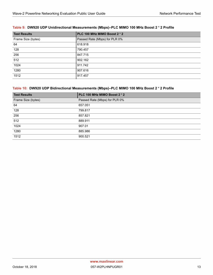
Table 9: DW920 UDP Unidirectional Measurements (Mbps)–PLC MIMO 100 MHz Boost 2 ˟ 2 Profile
Test Results PLC 100 MHz MIMO Boost 2 ˟ 2Frame Size (bytes) Passed Rate (Mbps) for PLR 0%
64 618.918
128 790.457
256 847.715
512 902.162
1024 911.742
1280 907.616
1512 917.457
Table 10: DW920 UDP Bidirectional Measurements (Mbps)–PLC MIMO 100 MHz Boost 2 ˟ 2 Profile
Test Results PLC 100 MHz MIMO Boost 2 ˟ 2Frame Size (bytes) Passed Rate (Mbps) for PLR 0%
64 657.051
128 799.817
256 857.821
512 889.911
1024 907.01
1280 885.986
1512 900.521
www.maxlinear.comOctober 18, 2018 057-W2PLHNPUGR01 13
Wave-2 Powerline Networking Evaluation Public User Guide Powerstrip Test
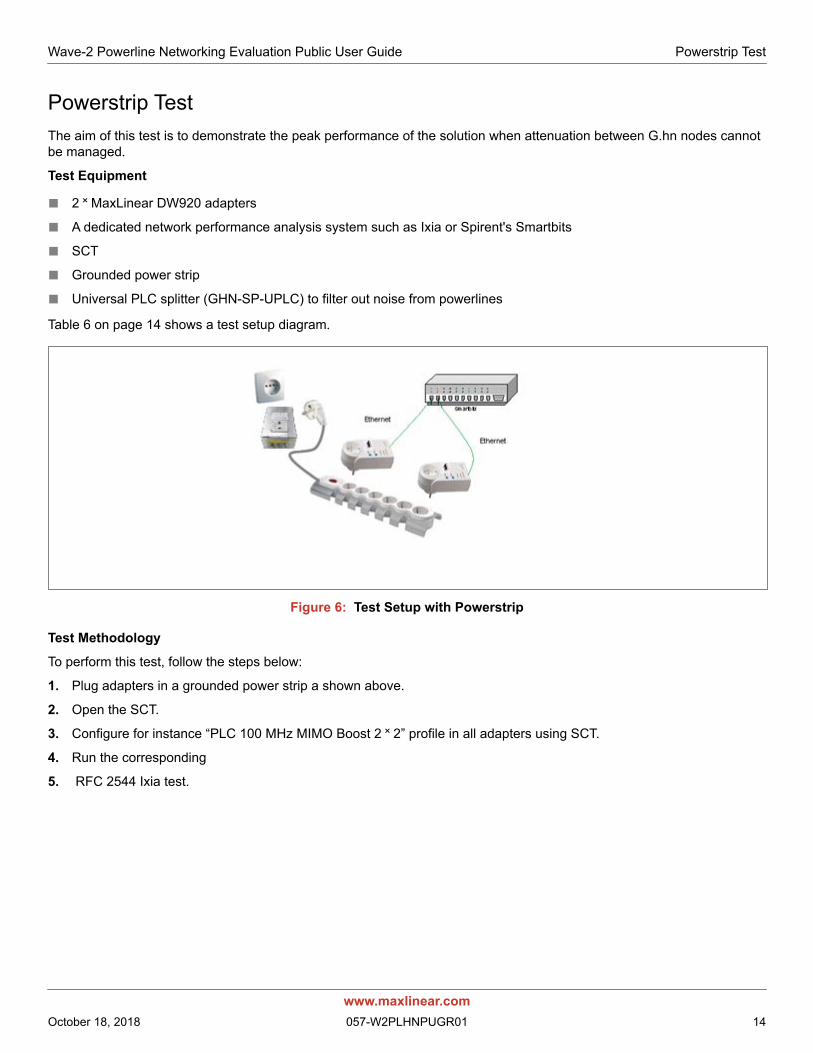
Powerstrip TestThe aim of this test is to demonstrate the peak performance of the solution when attenuation between G.hn nodes cannot be managed.
Test Equipment
■ 2 ˟ MaxLinear DW920 adapters
■ A dedicated network performance analysis system such as Ixia or Spirent's Smartbits
■ SCT
■ Grounded power strip
■ Universal PLC splitter (GHN-SP-UPLC) to filter out noise from powerlines
Table 6 on page 14 shows a test setup diagram.
Figure 6: Test Setup with Powerstrip
Test Methodology
To perform this test, follow the steps below:
1. Plug adapters in a grounded power strip a shown above.
2. Open the SCT.
3. Configure for instance “PLC 100 MHz MIMO Boost 2 ˟ 2” profile in all adapters using SCT.
4. Run the corresponding
5. RFC 2544 Ixia test.
www.maxlinear.comOctober 18, 2018 057-W2PLHNPUGR01 14
Wave-2 Powerline Networking Evaluation Public User Guide Powerstrip Test
6. Alternatively, run iperf as follows:
c. Perform a TCP throughput test typing the following commands in a console window:
Server side (PC1): iperf –s –w 32K
Client side (PC2): iperf –c [Server IP] –w 32K –i 1 –t 60 –P 32
d. To test UDP throughput and jitter type the following:
Server side (PC1): iperf -s –i 1 –u –w 512K
Client side (PC2): iperf -c [Server IP] -i 1 –u –w 512K -t 60 -b X
where X is the injected bandwidth (in bps) for the application. Select an X value of around 950M.
7. Alternatively, run PCATTCP as follows:
a. Perform a TCP throughput test typing the following commands in a console window:
Server side (PC1): PCATTCP.exe -r –c -f m -b 512000
Client side (PC2): PCATTCP.exe -t -f m –u -n 300000 <server IP>
b. To test UDP throughput type the following:
Server side (PC1): PCATTCP.exe -r –c –f m –u
Client side (PC2): PCATTCP.exe -t -f m –u -n 300000 <server IP>
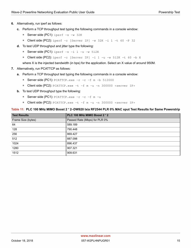
Table 11: PLC 100 MHz MIMO Boost 2 ˟ 2–DW920 Ixia RF2544 PLR 0% MAC xput Test Results for Same Powerstrip
Test Results PLC 100 MHz MIMO Boost 2 ˟ 2Frame Size (bytes) Passed Rate (Mbps) for PLR 0%
64 589.189
128 790.448
256 869.427
512 887.098
1024 896.437
1280 907.321
1512 909.631
www.maxlinear.comOctober 18, 2018 057-W2PLHNPUGR01 15
Wave-2 Powerline Networking Evaluation Public User Guide Power Mask and Notches Test
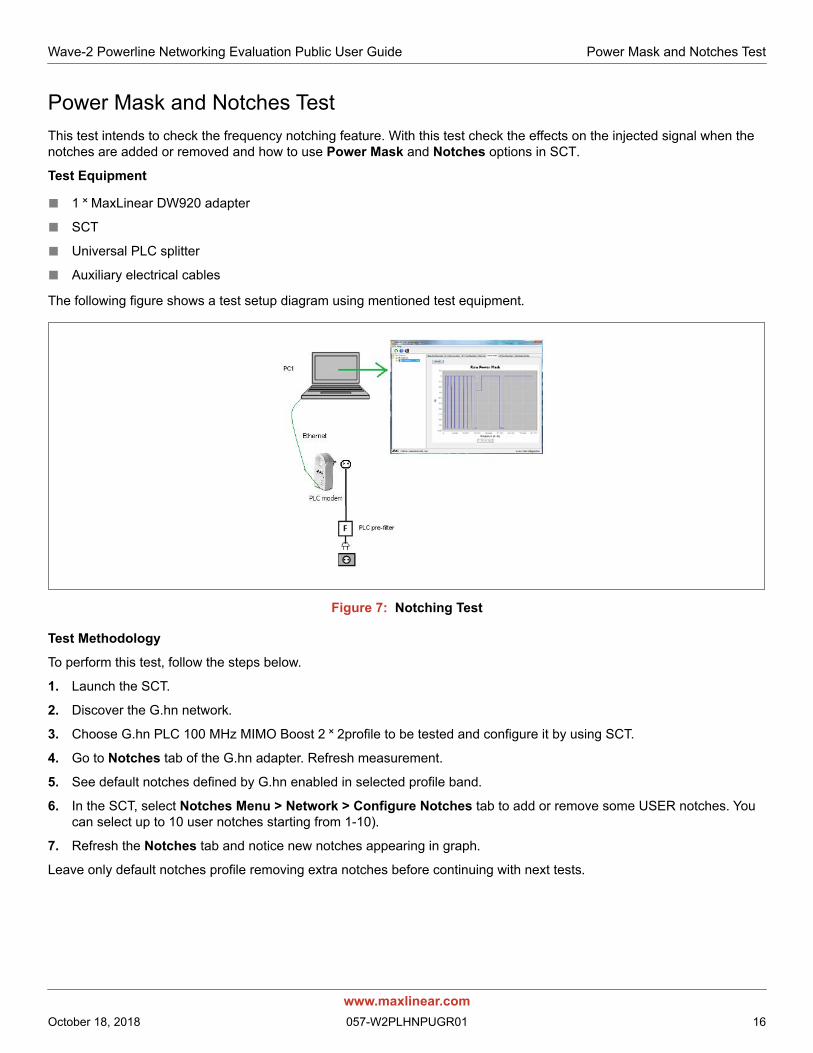
Power Mask and Notches TestThis test intends to check the frequency notching feature. With this test check the effects on the injected signal when the notches are added or removed and how to use Power Mask and Notches options in SCT.
Test Equipment
■ 1 ˟ MaxLinear DW920 adapter
■ SCT
■ Universal PLC splitter
■ Auxiliary electrical cables
The following figure shows a test setup diagram using mentioned test equipment.
Figure 7: Notching Test
Test Methodology
To perform this test, follow the steps below.
1. Launch the SCT.
2. Discover the G.hn network.
3. Choose G.hn PLC 100 MHz MIMO Boost 2 ˟ 2profile to be tested and configure it by using SCT.
4. Go to Notches tab of the G.hn adapter. Refresh measurement.
5. See default notches defined by G.hn enabled in selected profile band.
6. In the SCT, select Notches Menu > Network > Configure Notches tab to add or remove some USER notches. You can select up to 10 user notches starting from 1-10).
7. Refresh the Notches tab and notice new notches appearing in graph.
Leave only default notches profile removing extra notches before continuing with next tests.
www.maxlinear.comOctober 18, 2018 057-W2PLHNPUGR01 16
Wave-2 Powerline Networking Evaluation Public User Guide Neighboring Networks Test
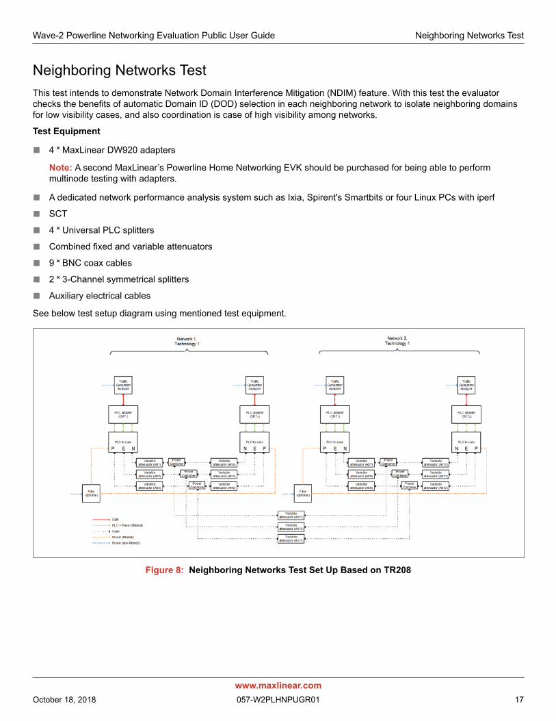
Neighboring Networks TestThis test intends to demonstrate Network Domain Interference Mitigation (NDIM) feature. With this test the evaluator checks the benefits of automatic Domain ID (DOD) selection in each neighboring network to isolate neighboring domains for low visibility cases, and also coordination is case of high visibility among networks.
Test Equipment
■ 4 ˟ MaxLinear DW920 adapters
Note: A second MaxLinear’s Powerline Home Networking EVK should be purchased for being able to perform multinode testing with adapters.
■ A dedicated network performance analysis system such as Ixia, Spirent's Smartbits or four Linux PCs with iperf
■ SCT
■ 4 ˟ Universal PLC splitters
■ Combined fixed and variable attenuators
■ 9 ˟ BNC coax cables
■ 2 ˟ 3-Channel symmetrical splitters
■ Auxiliary electrical cables
See below test setup diagram using mentioned test equipment.
Figure 8: Neighboring Networks Test Set Up Based on TR208
www.maxlinear.comOctober 18, 2018 057-W2PLHNPUGR01 17
Wave-2 Powerline Networking Evaluation Public User Guide Neighboring Networks Test
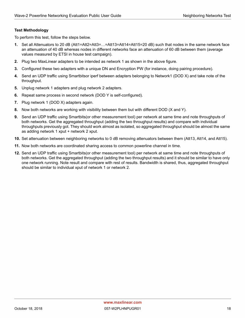
Test Methodology
To perform this test, follow the steps below.
1. Set all Attenuators to 20 dB (Att1=Att2=Att3=…=Att13=Att14=Att15=20 dB) such that nodes in the same network face an attenuation of 40 dB whereas nodes in different networks face an attenuation of 60 dB between them (average values measured by ETSI in house test campaign).
2. Plug two MaxLinear adapters to be intended as network 1 as shown in the above figure.
3. Configured these two adapters with a unique DN and Encryption PW (for instance, doing pairing procedure).
4. Send an UDP traffic using Smartbitsor iperf between adapters belonging to Network1 (DOD X) and take note of the throughput.
5. Unplug network 1 adapters and plug network 2 adapters.
6. Repeat same process in second network (DOD Y is self-configured).
7. Plug network 1 (DOD X) adapters again.
8. Now both networks are working with visibility between them but with different DOD (X and Y).
9. Send an UDP traffic using Smartbits(or other measurement tool) per network at same time and note throughputs of both networks. Get the aggregated throughput (adding the two throughput results) and compare with individual throughputs previously got. They should work almost as isolated, so aggregated throughput should be almost the same as adding network 1 xput + network 2 xput.
10. Set attenuation between neighboring networks to 0 dB removing attenuators between them (Att13, Att14, and Att15).
11. Now both networks are coordinated sharing access to common powerline channel in time.
12. Send an UDP traffic using Smartbits(or other measurement tool) per network at same time and note throughputs of both networks. Get the aggregated throughput (adding the two throughput results) and it should be similar to have only one network running. Note result and compare with rest of results. Bandwidth is shared, thus, aggregated throughput should be similar to individual xput of network 1 or network 2.
www.maxlinear.comOctober 18, 2018 057-W2PLHNPUGR01 18
Wave-2 Powerline Networking Evaluation Public User Guide Point-to-Multipoint Traffic Test in Flat Channels
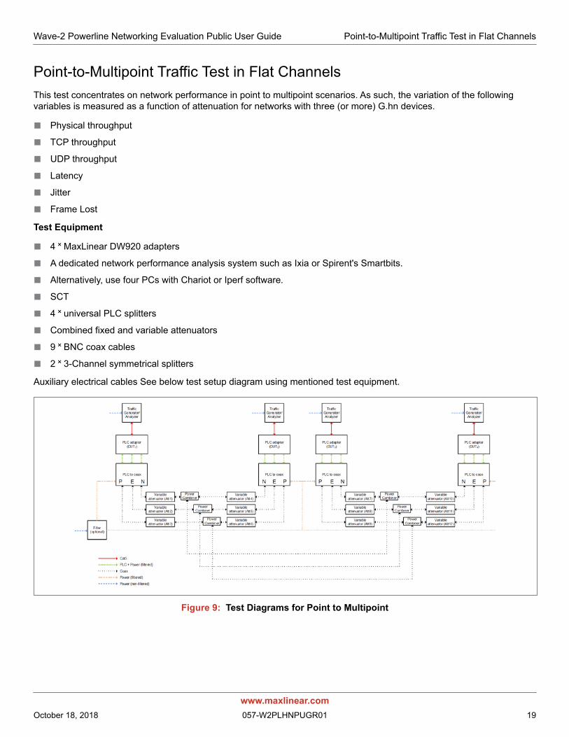
Point-to-Multipoint Traffic Test in Flat ChannelsThis test concentrates on network performance in point to multipoint scenarios. As such, the variation of the following variables is measured as a function of attenuation for networks with three (or more) G.hn devices.
■ Physical throughput
■ TCP throughput
■ UDP throughput
■ Latency
■ Jitter
■ Frame Lost
Test Equipment
■ 4 ˟ MaxLinear DW920 adapters
■ A dedicated network performance analysis system such as Ixia or Spirent's Smartbits.
■ Alternatively, use four PCs with Chariot or Iperf software.
■ SCT
■ 4 ˟ universal PLC splitters
■ Combined fixed and variable attenuators
■ 9 ˟ BNC coax cables
■ 2 ˟ 3-Channel symmetrical splitters
Auxiliary electrical cables See below test setup diagram using mentioned test equipment.
Figure 9: Test Diagrams for Point to Multipoint
www.maxlinear.comOctober 18, 2018 057-W2PLHNPUGR01 19
Wave-2 Powerline Networking Evaluation Public User Guide Point-to-Multipoint Traffic Test in Flat Channels
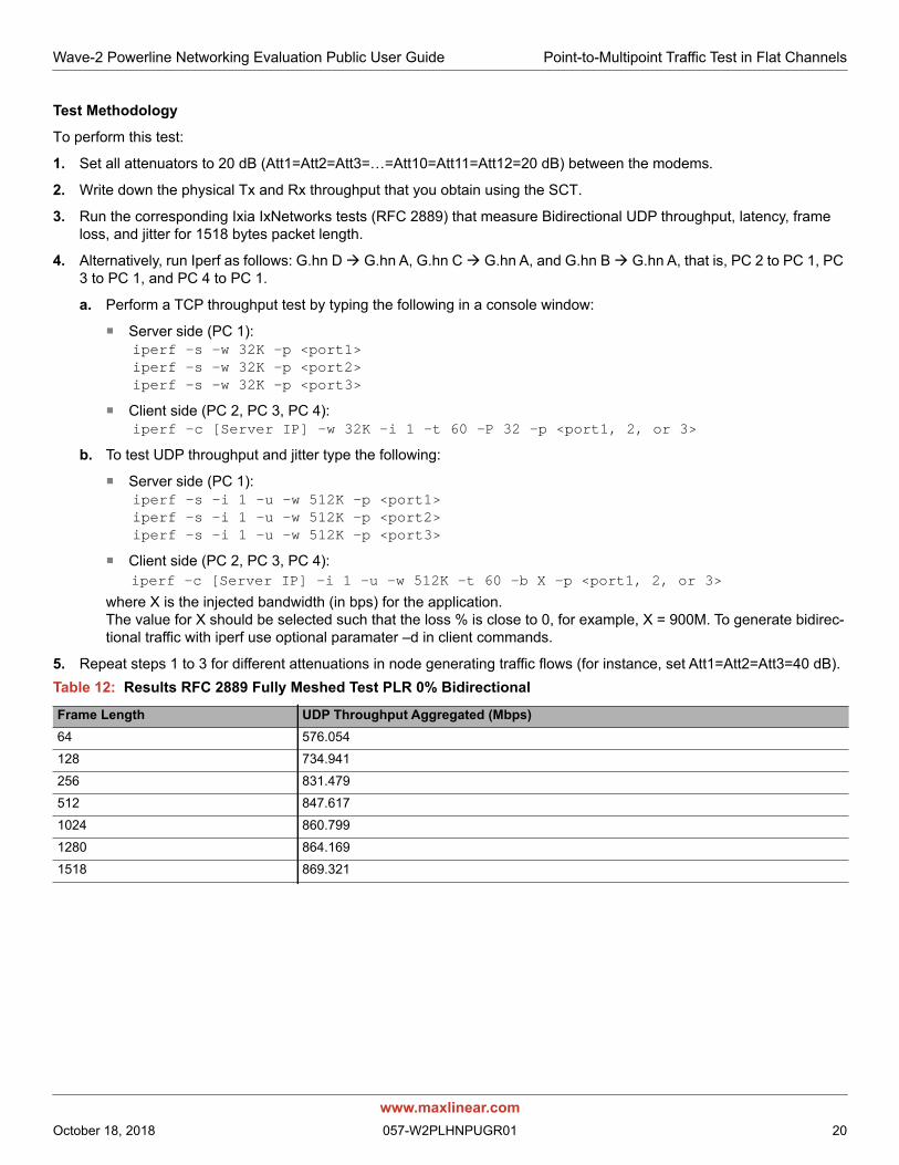
Test Methodology
To perform this test:
1. Set all attenuators to 20 dB (Att1=Att2=Att3=…=Att10=Att11=Att12=20 dB) between the modems.
2. Write down the physical Tx and Rx throughput that you obtain using the SCT.
3. Run the corresponding Ixia IxNetworks tests (RFC 2889) that measure Bidirectional UDP throughput, latency, frame loss, and jitter for 1518 bytes packet length.
4. Alternatively, run Iperf as follows: G.hn D G.hn A, G.hn C G.hn A, and G.hn B G.hn A, that is, PC 2 to PC 1, PC 3 to PC 1, and PC 4 to PC 1.
a. Perform a TCP throughput test by typing the following in a console window:
Server side (PC 1): iperf -s -w 32K –p <port1>iperf -s -w 32K –p <port2>iperf -s -w 32K –p <port3>
Client side (PC 2, PC 3, PC 4):iperf -c [Server IP] -w 32K -i 1 -t 60 -P 32 –p <port1, 2, or 3>
b. To test UDP throughput and jitter type the following:
Server side (PC 1): iperf -s -i 1 -u -w 512K –p <port1>iperf -s -i 1 -u -w 512K –p <port2>iperf -s -i 1 -u -w 512K –p <port3>
Client side (PC 2, PC 3, PC 4): iperf -c [Server IP] -i 1 -u -w 512K -t 60 -b X –p <port1, 2, or 3>
where X is the injected bandwidth (in bps) for the application. The value for X should be selected such that the loss % is close to 0, for example, X = 900M. To generate bidirec-tional traffic with iperf use optional paramater –d in client commands.
5. Repeat steps 1 to 3 for different attenuations in node generating traffic flows (for instance, set Att1=Att2=Att3=40 dB)..
Table 12: Results RFC 2889 Fully Meshed Test PLR 0% Bidirectional
Frame Length UDP Throughput Aggregated (Mbps)64 576.054
128 734.941
256 831.479
512 847.617
1024 860.799
1280 864.169
1518 869.321
www.maxlinear.comOctober 18, 2018 057-W2PLHNPUGR01 20

Wave-2 Powerline Networking Evaluation Public User Guide Field Evaluation and Tests
Field Evaluation and TestsField evaluation is the process of testing a G.hn technology in a real world environment. The main differences between evaluating G.hn in the field and in the laboratory are listed below.
■ The field environment is more difficult to control than the lab environment.
■ The results of a particular field test may be more difficult to reproduce than those of a lab test.
■ The signal environment in a field test is dynamic and the characteristics of the communication channel change along the time.
■ The field test environment can have a wide variety of interfering devices, which might affect the performance of equipment.
■ The field environment has attenuation profiles depending on the frequency.
The results achieved in a field environment could be affected by a wide range of variables; the key elements are listed below.
■ The size of the home where the tests are being performed.
■ The way in which electricity is distributed: a single phase in all outlets or whether there are multiple phases going to different outlets in the home.
■ Ground presence in the house.
■ The electrical layout of the home in terms of the locations of electrical distribution.
■ The age of the home and the type of electrical cabling used.
■ The range of interfering devices connected to the electrical network.
Planning a Field Test CampaignDespite the fact that the field environment is far more variable than the laboratory environment, it is possible to improve the quality of the test campaign by following an appropriate procedure.
The suggested steps to be performed when executing a field test campaign are listed below.
1. Determine the size of the testing campaign, resources and equipment required.
2. Determine the types of homes which is used in the campaign.
3. Select the tests to be performed.
4. Select G.hn profiles to be tested
5. Select the power points in each home to be tested (typical outlet where an IPTV service would be installed, for instance near the TV, in the home office, etc.).
6. Collect results.
7. Collate and present results.
www.maxlinear.comOctober 18, 2018 057-W2PLHNPUGR01 21

Wave-2 Powerline Networking Evaluation Public User Guide Planning a Field Test Campaign
Determining the Size of the Testing CampaignCorrect dimensioning of the test campaign beforehand is greatly help in ensuring the correct planning of the process. A field test in a single home usually takes a few hours performing typical throughput tests and depending on the number of chosen socket combinations.
To get a more complete view of the capabilities of the technologies, the results of several homes can be compiled. Increasing the sample size can improve the statistical confidence in results.
The basic equipment required to undertake the campaign is listed below.
■ Two G.hn adapters
■ Laptop PCs, enough powerful to support throughputs close to 1Gbps in TCP and UDP.
■ Testing software (iperf, Chariot or similar).
In case of ISP operators it is also recommended to use real IPTV service in the evaluation interconnecting home gateway and STBs through adapters as they are used in real deployments.
Determine the Types of HomesHome types vary greatly according to geographical area, demographic groups and a wide range of other factors. The home-wide performance of powerline products is therefore a function of all of these variables. When selecting homes for a field trial campaign it is important that the homes selected are representative for the target market to use the technology. For example, the homes selected for a product targeted at IPTV for the Asian market is radically different from those chosen for a high-end home networking product for the US market.
To summarize, homes should be selected to provide a representative sample of the following variables for the chosen application, market, and geographical area.
■ Floor area
■ Construction type (single tenant unit or apartment building)
■ Number of floors
■ Age
■ Electrical layout (three phases or single phase) and ground presence
■ Selected outlets description
■ Rooms in the house
Selecting the Tests to Be PerformedDepending on the target application, and the resources available, any of the tests mentioned in the previous sections can be done in the field environment in a similar way. Typically, TCP and/or UDP throughput, latency, jitter and frame lost measurements are some examples commonly chosen, as well as testing real services with which the technology are used (for instance, IPTV service, HD streaming from video server to video player,…).
Note: A very important point in case of performing benchmarking of different technologies is to do a test in one location for each technology almost at the same moment to avoid that the evolution of the communication channel along time affect the results. For example, execute test X for technology A in a socket combination and after it finishes execute same test X for technology B in same socket combination, same for C, and so on. After that, going to next socket combination and repeat the process.
www.maxlinear.comOctober 18, 2018 057-W2PLHNPUGR01 22

Wave-2 Powerline Networking Evaluation Public User Guide Planning a Field Test Campaign
Select PLC Profiles to Be TestedMaxLinear G.hn technology provides several configuration profiles that can be tested to choose the best initial configuration for a further commercial deployment. Currently main profile to be tested in MaxLinear Wave-2 G.hn solution is “PLC 100 MHz MIMO Boost 2˟2”.
Selecting the Points to Be TestedThe time required to perform tests and collate results can be reduced, using the fact that results can be treated statistically. So even with a subset of results it is possible to interpolate the results for any home.
In the field, the electrical layout of the home in terms of wire length, type, and layout, is very seldom available. For this reason, field tests are generally aimed at assessing the statistical probability of achieving a particular performance between random outlet pairs, or between outlet pairs in random rooms. The number of measurements that can be made is therefore proportional to the square of the number of outlet pairs selected.
For example, if there are seven outlets selected for testing PHY speed, there are 21 connections between outlets, each of which produces a different result depending on whether the transmission or reception path is tested giving a total of 42 combinations. The recommended number of outlets for testing is three to five per home, for instance the typical ones in which final users usually plug the G.hn adapters.
For the correct collation of results in any statistical experiment, a proper random sample selection process is necessary, and for G.hn field tests there are two possibilities:
■ Randomly select a number of outlets in the home: This technique provides the inter-socket performance of the technology.
■ Randomly select a outlet in each room of the home: This technique provides the inter-room performance of the technology.
Collecting the ResultsTest results can be collected for each socket pair, performing the relevant throughput tests. Below some tables are presented that could be used as a model for evaluator’s tests.Table 13: Example of General Field Test Information
Test Parameters
Date test performed
Home tested
Modem “A” MAC Address, firmware loaded and reference design
Modem “B” MAC Address, firmware loaded and reference design
Home floor area (m2)
Electrical phase distribution
Ground presence
Building type
Country and city
Age (years)
Number of floors
Rooms in the house
www.maxlinear.comOctober 18, 2018 057-W2PLHNPUGR01 23

Wave-2 Powerline Networking Evaluation Public User Guide Planning a Field Test Campaign
.
Table 14: Example of Outlet Description
Socket No1
2
3
4
5
Table 15: Example of Outlets Description
Transmit Receive
Out
let P
air
Phys
ical
Thr
ough
put
TCP
Thro
ughp
ut
UD
P Th
roug
hput
Late
ncy
Jitte
r
Fram
e Lo
st
Phys
ical
Thr
ough
put
TCP
Thro
ughp
ut
UD
P Th
roug
hput
Late
ncy
Jitte
r
Fram
e Lo
st
1-2
1-3
1-4
1-5
2-3
2-4
2-5
3-4
3-5
4-5
www.maxlinear.comOctober 18, 2018 057-W2PLHNPUGR01 24

Powerline Wave-2 Powerline Networking Evaluation Public User Guide Disclaimer
Appendix A: Safety RecommendationsTo protect yourself from injuries and avoid damage of the device, always observe the following safety instructions when installing and working with the EVK.
Avoiding InjuriesWarning!
– Electrical current!
– Electrical current from power and communications cables can be hazardous.
– Never touch any electrical elements with bare hands
To avoid potential shock hazards:
■ Do not remove the enclosure with the adapter plugged to mains.
■ Do not manipulate the circuits and/or components with enclosure removed and adapter powered.
■ Do not touch any component from the boards when it is plugged into the mains.
■ Do not carry out any installation, maintenance, or (re)configuration work during a thunderstorm.
■ Do not connect or disconnect any power cables during a thunderstorm.
■ For installation in a hot-plug system, observe the safety instructions specific to this system.
Read the relevant documentation.
Warning! The electrical safety of this EVK has not been fully evaluated against the requirements of the EN 60950-1:2006 (IEC 60950-1:2005) standard and this EVK does not fulfill with all the relevant electrical safety requirements stated in such standard.
The content of this document is furnished for informational use only, is subject to change without notice, and should not be construed as a commitment byMaxLinear, Inc. MaxLinear, Inc. assumes no responsibility or liability for any errors or inaccuracies that may appear in the informational content contained in thisguide. Complying with all applicable copyright laws is the responsibility of the user. Without limiting the rights under copyright, no part of this document may bereproduced into, stored in, or introduced into a retrieval system, or transmitted in any form or by any means (electronic, mechanical, photocopying, recording, orotherwise), or for any purpose, without the express written permission of MaxLinear, Inc.
Maxlinear, Inc. does not recommend the use of any of its products in life support applications where the failure or malfunction of the product can reasonably beexpected to cause failure of the life support system or to significantly affect its safety or effectiveness. Products are not authorized for use in such applications unlessMaxLinear, Inc. receives, in writing, assurances to its satisfaction that: (a) the risk of injury or damage has been minimized; (b) the user assumes all such risks; (c)potential liability of MaxLinear, Inc. is adequately protected under the circumstances.
MaxLinear, Inc. may have patents, patent applications, trademarks, copyrights, or other intellectual property rights covering subject matter in this document. Exceptas expressly provided in any written license agreement from MaxLinear, Inc., the furnishing of this document does not give you any license to these patents,trademarks, copyrights, or other intellectual property.
MaxLinear, the MaxLinear logo, and any MaxLinear trademarks, MxL, Full-Spectrum Capture, FSC, G.now, AirPHY and the MaxLinear logo are all on the productssold, are all trademarks of MaxLinear, Inc. or one of MaxLinear’s subsidiaries in the U.S.A. and other countries. All rights reserved. Other company trademarks andproduct names appearing herein are the property of their respective owners.
© 2018 MaxLinear, Inc. All rights reserved.
MaxLinear, Inc.5966 La Place Court, Suite 100Carlsbad, CA 92008760.692.0711 p.760.444.8598 f.
www.maxlinear.com