Embed Size (px)
Citation preview

ELECTRONIC TECHNOLOGY SERIES
•·1• ., .•' .' ., . ~~~ .. ,: .. , .. '
_;,,'~ ? ,: ·.'·':. ·:-i, f; t1 · .... ,,,,. ,• .
' • ~~· :: ... • ',,J •• .,, ., I:,.,•
PROPAGATION .·,· ..
.... •'., .. ·' . ' ·. . ~ ··.- . , •. ; ; ; : ~i :· .. ...
' . . ~· ~. ',: . . • ',{ j.
··1 ·.• .,
-..·,,.,,_·
,,
a publication

WAVE PROPAGATION
Edited by
Alexander Schure, Ph.D., Ed. D.
$1.25
JOHN F. RIDER PUBLISHER, INC.
116 West 14th Street • New York 11, N. Y.

Copyright March 1957 by
JOHN F. RIDER PUBLISHER, INC.
All rights reserved. This book or parts thereof may not be reproduced in any form or in any language
without permission of the publisher.
Library of Congress Catalog Card No. 56-11339
Printed in the United States of America

PREFACE
A thorough understanding of the basic principles of wave propagation is a most useful tool for the electronic technician, engineer or amateur. Much of the satisfaction of transmitter work arises from the awareness and best possible use of propagation variations occasioned by natural phenomena. A working knowledge of essential wave propagation factors is not too difficult to attain. This book has been organized to accomplish this aim by helping the student understand the more important ideas pertaining to wave propagation.
Specific attention has been given to the nature and use of the electromagnetic wave in such areas as wave motion, frequencywavelength relationships, radiation, field intensity, wave fronts and polarization. Analyses are given of the natures of sky waves, ground waves, wave reflection, refraction and diffraction as they pertain to the propagation of electromagnetic waves. A general discussion of the effect of atmosphere on radio transmission includes details of the regions which exert different influences on the passage of an electromagnetic wave, namely the ionosphere, stratosphere, and troposphere. In addition to an explanation of ground wave and sky wave propagation, some details are given dealing with scatter propagation.
The total materials presented are sufficient to give an interested reader the essential elements of wave propagation theory. Specific discussions of antennas or transmission lines as they relate to and affect wave propagation have not been included here, since these are the subjects of separate review books in this series.
Grateful acknowledgment is made to the staff of the New York Technical Institute for its assistance in the preparation of the manuscript of this book.
New York, N. Y. March 1957
V
A. s.

CONTENTS
Chapter Page
1 Nature and Use of Electromagnetic Waves
2 How Electromagnetic Waves are Propagated 12
3 Effect of Atmosphere on Radio Transmission 18
4 Normal Tropospheric Propagation 31
5 Scatter Propagation . 37
6 Special Ionospheric Effects at VHF and UHF 47
vii

Chapter 1
NATURE AND USE OF ELECTROMAGNETIC WAVES
1. lntrocludion
Propagation is the process of sending or transmitting energy from one place to another. When applied to radio waves, it designates the conditions and methods governing the progress of these waves from the time they leave the transmitting antenna until they are intercepted by a receiving antenna. Quality and dependability of radio transmission vary widely with such factors as time of day, time of year, sunspot cycle, frequency, polarization, and the radio path.
A knowledge of wave propagation is essential in understanding the operation of radio communicaion, television, radar, and other electronic systems.
All such systems use a transmitter to produce a signal, which is then applied through a transmission line to a transmitting antenna. The signal is radiated from this antenna in the form of electromagnetic waves. A portion of the energy carried by these waves may be absorbed in a given receiving antenna, from which it is applied through another transmission line to the receiver. The energy absorbed by each receiving system is so small that any number of receiving antennas may intercept the transmissions from one transmitter.
Figure 1 is a representation of a simple radio communication system. Note that in this system the electromagnetic wave travels

2 WAVE PROPAGATION
(is propagated) through the earth's atmosphere, although this is not a requirement for the utilization of electromagnetic radiations. Radiations from distant galaxies reach the earth through a virtually perfect vacuum.
The successful use of a radio communication system depends primarily on the distance between the transmitter and the receiver, the sensitivity of the receiver, and the power and efficiency of the transmitter. However, other factors such as atmospheric noise, changes in the humidity and temperature of the air, and
RECEIVING ANTENNA
RADIO RECEIVER
Fig. 1. Radiation of spherical waves in a simple communications system.
the nature of the terrain between the receiver and transmitter can modify signal transmissions even though the distance, transmitter power level, and receiver sensitivity are all conducive to satisfactory results under normal conditions. In order to understand and evaluate these factors, it will be necessary to examine the nature of the electromagnetic wave.
2. Wave Motion
An electromagnetic wave travels through space in much the same manner as a wave in a pond of water. Consequently, the action

NATURE AND USE OF ELECTROMAGNETIC WAVES 3
of waves in water can be used as a physical illustration of these aspects of electromagnetic wave motion. When a stone falls into a pond, ripples are formed, as shown in Fig. 2. These waves consist of a series of regularly spaced crests and troughs, which move outward in concentric circles from the point at which the falling stone disturbed the water. The radii of these circles increase as the distance from the point of disturbance increases. Therefore, these waves are said to travel or propagate radially outward from the point of disturbance.
The distance or separation between any two adjacent troughs or crests is always the same. Since each crest and its adjacent trough
CRESTS OF WAVE
TROUGHS OF WAVE
FRONT VIEW
Fig. 2. Waves in water.
POINT AT WHICH FALLING STONE STRIKES WATER
CREST
TROUGH
WATER
form a single wave, the separation between two adjacent troughs or crests is equal to the wrwelength and is designated as ,\ (lambda) . The crest and trough of a water wave are at different vertical levels. The difference between the crest (or trough) level and the average level (level in absence of waves) is a quantity known as the wave amplitude.
When a stone is dropped into a pond, the amplitude of the first wave is larger than that of the second wave, the amplitude

4 WAVE PROPAGATION
of the second wave is larger than that of the third wave, and so forth. Thus, the waves produced gradually diminish in amplitude and ultimately disappear.
This action, of course, cannot be directly compared to that of electromagnetic waves, because the electromagnetic wave is produced continuously as long as a radio signal is being transmitted.
When the rate or frequency (times per second) at which waves are produced has the value f, the waves will travel outward at a velocity (V) equal to the product of the frequency (f) and the wavelength (A) . Thus
V ,\f (I)
V ,\ -f-
f = V ,\
The velocity of an electromagnetic wave in air is the same for all frequencies and is nearly equal to 300,000,000 meters (186, 000 miles) per second.
Thus a wave alternating at a frequency of 500 kilocycles per second (500,000 cycles per second) has a wavelength
,\ = ~ - !~~:~~~ = .372 miles or about 1964 feet
3. Radiation
Radio waves represent a form of electrical energy predicted by James Maxwell nearly a century ago. Basically, they are made up of constantly changing electric and magnetic fields, with the total energy of the wave divided equally between the two.
Michael Faraday proposed a useful method of mapping an electric field to show its direction and magnitude at a given point. Once the intensity and direction of the field were known, he imagined a unit square drawn perpendicular to the field at that point (Fig. 3A), and a sufficient number of lines cutting through the square to represent the magnitude of the electric field at that point. These lines of force are said to exist in the direction of the field (note arrowhead) . Faraday explained the attraction and repulsion between charged bodies by assuming that the lines of force are in

NATURE AND USE OF ELECTROMAGNETIC WAVES 5
a continual state of tension (like rubber bands) , and that they tend to repel each other laterally.
In Fig. 3B it can be seen that the lines of force leave the negatively charged body perpendicular to the surface and enter the positive body perpendicular to its surface. Since the lines are repelled from one another and tend to contract, the bodies tend to attract each other. In Fig. 3C the lines emerge from the two posi-
(A) (B)
(C)
Fig. 3. {A) Faraday's method of mapping field strength based upon the number' of electric lines passing through a unit square normal to the surface. Electric lines of force between (8) oppositely charged bodies and (C) bodies
having a like charge.
tive bodies shown and go to a negative body (too distant to show in the illustration). Mutual repulsion between these lines tends to create repulsion between the two bodies. It should be mentioned that the lines of force are not physical realities, but are used only to illustrate a somewhat elusive concept.
An electric field may be defined in another way. Assume that a capacitor having a plate separation of five meters is charged to a potential of 100 volts (Fig. 4) . Electric lines of force permeate the volume between the plates, and will be everywhere constant in density, save for an insignificant distortion at the ends. It is obvious

6 WAVE PROPAGATION
that if the potential at one plate is zero with respect to - IOO volts at the other plate, there is a change of IOO volts in a distance of 5 meters (or an increase of IOO volts/5 meters = 20 volts per meter) . It should be understood from this that a difference in potential exists between any two different points on a given electric line of force. There need not be a physical source of voltage in the region under consideration; reference to electric lines of force in "free space" specifies their magnitude as a given voltage difference per meter. Electric lines of force are vectors having direction and
ZERO VOLTS
l 20 VOLTS
PER METER
l -100 VOLTS
5 METERS
____ l
Fig. 4. The electric fleld of a capadtor.
magnitude. They also represent the direction of force applied to a small positively charged body placed in that field, in accordance with the equation:
F (dynes) Q (Statcoulombs)
E (statvolts per cm)
Now if the 100-volt source we have been considering were alternating, a current would flow through the wires connecting the capacitor with the source. The current would charge and discharge the capacitor, causing a polarity reversal during each cycle in accordance with basic theory. What happens inside the capacitor, however, cannot be completely described in terms of elementary electron theory. The idea that a kind of current flows from plate to plate inside the capacitor must be introduced.
It is a physical reality that an alternating voltage applied to a capacitor produces a current that flows into one plate and out of the other. This happens only when the voltage across the capacitor is changing; i.e., when the electric field between the plates is varying

NATURE AND USE OF ELECTROMAGNETIC WAVES 7
in magnitude. James Maxwell proposed that under these conditions, the current entering one plate did not stop, but continued to flow across the space between the plates. Indeed, one of Maxwell's original assumptions (upon which his famous theory of electromagnetism was based) is that a change in an electric field is equivalent in its electromagnetic effects to an actual flow of current. Maxwell called this current a displacement current; today the term space current is often applied.
Clearly then, a changing electric field always gives rise to a type of current, or equivalent current, that actually flows through space. In accordance with basic theory this space current - as well as the actual current in the wires - leads the applied voltage of the electric field in phase by 90 degrees. This concept is important for a mature understanding of the propagation of radio waves.
4. The Magnetic Field
Magnets that are free to move in space behave very much like electric poles in the sense that attraction and repulsion both occur, depending upon the orientation of the poles of the magnets. Moreover, the magnitude of these forces, like those in an electrostatic field, depends upon similar constants such as pole strength, separation, and the character of the medium in which the magnets are immersed.
The parallelism between electric and magnetic poles immediately suggests that there is a magnetic field in existence in the vicinity of magnetic poles. A magnetic field is often represented by lines of force pointing in the direction of the field, or in the diection of the force exerted upon a unit north pole placed in the field
As we shall show later, electric and magnetic fields produced by electric potentials and their accompanying currents are always perpendicular to each other with respect to direction; this inflexible "partnership" is one of the prime tenets of Maxwell's theory of electromagnetic radiations, and has been amply proven in both physical and mathematical terms by countless experiments.
5. Electromagnetic Waves
On the basis of classical theory, it can be shown that an accelerating electric charge will always radiate energy in the form of

8 WAVE PROPAGATION
electromagnetic waves. In an antenna, electronic charges (electrons) are made to accelerate, and this is what causes radiation. If these radio waves arc emitted from a point source (a source so small as to have only mathematical significance) they will expand spherically like a balloon being inflated. (See Fig. 5.) An increment of energy in a specific direction is called a ray. The rays
Fig. 5. Spherical propaga, tion from a point source.
are always perpendicular to the surface of the imaginary balloon, and thus diverge as the balloon increases in size. As the energy expands, its intensity per cubic unit of space must diminish, since the total energy is spread over a larger total volume. At a great distance, the surface of each successive "balloon" is nearly parallel to those of its neighbors. (This explains why radio waves are usually considered parallel to one another, except near the source.) This "surface" is called a wave front, and in relation to any point through which it passes, it may be regarded as a plane surface.

NATURE AND USE OF ELECTROMAGNETIC WAVES 9
If we examine a ray of a radio wave, we find that it is made up of electric and magnetic fields. The fields are perpendicular to one another and to the direction of travel (propagation) . The fields vary sinusoidally at the frequency of the source.
The simplest type of electromagnetic wave is shown in Fig. 6. Such a wave is a polarized wave; that is, the magnetic and electric
H
Eo
( B)
DIRECTION OF PROPAGATION
Fig. 6. (A) E and H components of the eledromagnetlc wave. (B) Vedor equivalent.
components do not oscillate in random directions, but are fixed. The polarization of a radio wave is taken as the orientation of the electric vector with respect to the earth. Thus a vertically polarized

10 WAVE PROPAGATION
wave (as shown in Fig. 6) possesses a vertical electric field (E) and a horizontal magnetic field (H) . The vectorial method of illustrating this is shown in Fig. 6B. For most communication purposes, the radio wave is either horizontally or vertically polarized.
A fundamental relationship showing the instantaneous value of the magnetic and electric fields as a function of velocity of propagation, distance from the source, and frequency of oscillation in terms of practical mks (meter-kilogram-second) units is:
Honst.) = H0 sin 27rf (t - : ) (2)
E (Inst.) = E 0 sin 271'f ~ - : ) (3)
Where: H(lnst.) = Instantaneous value of the magnetic vector in amperes per meter.
E (Inst.) = Instantaneous value of the electric vector in volts per meter.
H .. = Maximum value of the magnetic vector.
Eo = Maximum value of the electric vector.
t = Time (in seconds) required for the wave to reach a determined point in space.
f = Frequency in cps.
X = Distance in meters.
C = Velocity of electromagnetic radiation. (300,000,000 meters per second) .
The peak amplitude of either field at a given distance from the source may be given as a function of the radiated power:
60P E0 = 120H0 = - (4) r2
Where: P = Radiated power in_ watts (joules/sec) . r = Distance from the source in meters.
12071' and 60 carry the dimensions of ohms.
6. Review Questions
(1) What factors affect the successful use of a radio communication system? (2) Explain the nature of electromagnetic wave motion. (3) What is a wavelength? (4) Explain the meaning of the formula V = >. f.

NATURE AND USE OF ELECTROMAGNETIC WAVES 11
(5) What is an induction field? (6) How is electromagnetic wave energy radiated?· (7) Define: volts per meter; space current. (8) Give the fundamental relationship expressing the peak amplitude of
either field at a given distance from the source as a function of the radiated power.
(9) The electromagnetic wave is composed of E and H field components. What is the phase and amplitude relationship between these components?
(10) How does a horizontally polarized wave differ from a vertically polarized wave?

Chapter 2
HOW ELECTROMAGNETIC WAVES ARE PROPAGATED
7. Sky Waves
Electromagnetic waves can travel between a transmitter and a receiver in two principal ways. The first of these, known as sky wave propagation, is used primarily for long distance radio transmission.
In sky wave propagation, as described in more detail in Chaps. 3 and 5, the electromagnetic waves do not travel directly between the transmitter and receiver. Instead, these waves travel from the antenna up into the earth's atmosphere until they strike electrified regions (these regions are described in more detail in Chap. 3) , where their direction is then changed downward toward the receiving antenna.
Since the electrical characteristics of these regions change from day to day and even from hour to hour, sky wave propagation is variable. At times the sky wave is reflected downward at such an angle that it will not strike the receiving antenna, and thus no sky wave reception can occur.
8. Ground Waves
The second method by which electromagnetic waves travel from transmitter to receiver is known as ground wave propagation. Short distance radio transmission (for example, where a radio
12

HOW ELECTROMAGNETIC WAVES ARE PROPAGATED 13
broadcast originating in a city is received in the same city) takes place primarily by means of ground waves.
In ground wave propagation, as described in more c.letail in Chap. 3, the electromagnetic waves travel along the earth directly from the transmitter to the receiver. Propagation of the ground wave is determined by the electrical characteristics of the earth (note that a portion of the path can be over land and another
I NCI DE NT WAVE
DIRECTION OF/ E FIELD FOR
~"-'c,
~·l
Fig. 7. Wave Reflection.
\
DIRECTION OF E FIELD FOR REFLECTED Q WAVE
0-<_'(;
~\,,~
::(!~
portion over water) and by the manner in which the wave is bent or refracted because of the curvature of the earth. These electrical characteristics differ from place to place, but do not change with time. Consequently, ground wave propagation between a given transmitter and a given receiver generally remains constant.
9. Combination of Sky and Ground Waves
Occasionally, a transmitter and receiver will have to be placed in a location where reception is difficult. In a typical situation of this kind, ground wave reception by itself is not satisfactory, while the sky wave reception is too erratic.
When sky wave and ground wave transmission are used together, however, the received signal resulting from this combination can be of sufficient quality to provide adequate reception under average conditions. Unfortunately, the combination of sky waves and ground waves is often troublesome, because they get out of phase with each other and cause selective fading, as explained in Chap. 5.

14 WAVE PROPAGATION
10. Wave Reflection
Electromagnetic waves can be reflected from certain surfaces as light is reflected from a mirror.
Large smooth surfaces of good electrical conductivity, such as copper plate, are good reflectors for electromagnetic waves. The surface of the earth can be a good reflector, and (as will be shown in Chap. 3) the electrically conductive layers of the earth's atmosphere are also good reflectors.
Figure 7 shows an electromagnetic wave being reflected from a smooth electrically-conductive surface. As in the case of light waves, the angle of incidence is always equal to the angle of reflection. Note also the change of phase of the E field.
11. Combined Refraction and Reflection
For reasons that will be analyzed in the next chapter, diffe,ent regions of the upper atmosphere are subject to electrical
REGION OF LOWER ELECTRICAL
ACTIVITY
Fig. 8. Reflection and refraction of an electromagnetic wave as It passes the boundary between two media of different electrical density.
disturbances of various intensities. Although the velocity of an electromagnetic wave is generally considered constant in a vacuum - that is, in a medium such as "empty" space - the presence of electrical particles in varying states of excitation produces changes in the wave's velocity. In highly electrified regions, the velocity of

HOW ELECTROMAGNETIC WAVES ARE PROPAGATED 15
propagation is greater than in a space where little or no electrification exists. As the medium changes its character due to the action of the sun or of cosmic rays, boundaries between regions of
NON ·ELECTRIFIED REGION
A~
~
/4 ~ :fjjf WAVEFRONTS
~ ~ ~
Fig. 9. Refraction due to change of velocity.
differing electrification make their appearance; these are not sharply defined because, by the very nature of the causative agents, the variations in wave-carrying ability are inevitably gradual. For the purposes of this preliminary discussion, however, we shall assume a sharp separation between media of different atmospheric character and call this the boundary, as in Fig. 8.
An electromagnetic wave, rising from the earth and striking the boundary at an angle of 90 degrees, is slowed down uniformly all along its wave front. However, if the wave meets the boundary at an angle other than 90 degrees, as in Fig. 8, one portion of the wave is reflected and another portion penetrates the boundary. As it emerges on the other side, its direction is no longer the same as that of the incident wave. This bending process is called refraction and may be explained by referring to Fig. 9 and the following text.
Consider wave front A-B. Since the speed of the wave front is greater in the electrified than in the nonelectrified region, point A of the incident wave front advances over distance A-A' in the same period of time in which point B moves through the smaller distance B-B'. B-B' is a smaller distance because the velocity is lower in this region.

16 WAVE PROPAGATION
As a result of the inequality of the distances covered in a unit time, the wave front no longer presents the same angle to the boundary as it did in the incident wave. Hence the direction of propagation has been altered.
Refraction always occurs when an electromagnetic wave passes from one medium to another at an angle other than 90 degrees, provided that the two media have different intensities of electrifica-
E FIELD BUILDING
-...._ - ..,_ -..1. _ ...1.----AREA OF
_,--.:::.--DIFFRACTION _.....,.-..,.- I
WAVE PROPAGATION DIRECTION
Fig. 10. Wave diffraction.
tion. The extent to which refraction occurs is dependent upon the ratio of velocities in the two media. This ratio is called the refractive index and may be used to compute the amount of bending that may be expected at any angle.
12. Wave Diffraction
When a light wave in an otherwise dark room shines on the edge of an opaque object, it will be found that the object will not cast a sharply outlined shadow; the shadow will be somewhat fuzzy, because the light waves are bent or diffracted around the edge of the object and decrease the area of total shadow. The diffraction of light waves is very small.
Electromagnetic radio waves are diffracted in the same manner, but to a greater extent, as shown in Fig. 10. Thus they can be received even when there is an obstruction such as a building between a transmitter and a receiver.
Diffraction can be an important consideration for long distance reception, because the earth, due to its curvature, can obstruct waves travelling directly from a transmitter to a receiver. To a small

HOW ELECTROMAGNETIC WAVES ARE PROPAGATED 17
degree, diffraction overcomes this obstruction. This effect is described in more detail in Chap. 4.
13. Review Questions
(1) What are the two principal ways in which waves can travel between a transmitter and a 1·eceiver.
(2) Wave propagation over short distances normally invoh·es sky wave propagation. True or False?
(3) Is sky wave propagation more useful than ground wave propagation? Explain.
(4) Does wave refraction always occur when a wave passes from one medium into another?
(5) Define refractive index. (6) Can radio waves be received when there is an obstruction between the
transmitter and the receiver? (7) What is the difference between refraction and diffraction? (8) The refractive index of water determines the amount of refraction of a
wave passing from air into water at an angle of 90 degrees. True or False?
Chapter 3
EFFECT OF ATMOSPHERE ON RADIO TRANSMISSION
14. General Discussion
The atmosphere of the earth is not uniform. Moisture content, density, and temperature changes in the atmosphere occur erratically at various times. Moreover, the composition of the atmosphere is affected by geographical location. This lack of uniformity influences the passage of electromagnetic waves through the atmosphere in many ways. A knowledge of the composition of the earth's atmosphere is essential to an understanding of the effects of atmosphere on the uniformity of wave propagation. As will be explained in more detail in the remaining sections of this chapter, the atmosphere can be regarded as being formed from three separate adjacent regions, each of which exerts different influences on the passage of an electromagnetic wave. These regions are known respectively as the troposphere, the stratosphere, and the ionosphere.
An understanding of the effects of these regions is further complicated by variations in the frequency of the transmitted waves; low frequency waves behave differently from high frequency waves. For ease in identification, radio frequencies are normally classified in ranges as shown in Table I.
15. Wave Types
There are a number of paths by which a radio wave may reach a receiving antenna. Waves traveling these paths are generally
18
EFFECT OF ATMOSPHERE ON RADIO TRANSMISSION 19
given specific names. By far the most important ones are the ground wave, the sl,y wave, and the space wave.
The term ground wave is generally applied to waves that travel from the transmitting to the receiving antenna with the bottom ot the wave front touching the ground, as illustrated in Fig. 11. The wave is always vertically polarized, because any horizontal compon• ent existing in the wave is essentially shorted by the earth.
As the ground wave progresses outward from the transmitting antenna, it sets up a minute electrical current within the earth directly beneath the wave. The energy for this earth current is always supplied by the wave above; the two are inseparable. In addition to creating this current, the wave will continue to supply energy in order to lessen inherent power losses within the earth. These power losses are determined by the frequency of operation and the conductive properties of the ground. Clearly, then, the ground wave will suffer less attenuation over salt water than over dry, sandy soil. The power losses, however, are not purely resistive, but significantly reactive. For this reason the frequency of the wave is the primary determinant in ground wave propagation.
As the frequency is increased, earth losses increase, so that for frequencies much above one megacycle the ground wave is virtually useless, except for local coverage. As a matter of fact, at television frequencies, the attenuation becomes so great that the ground wave is essentially useless at distances as short as one mile from the transmitter.
The energy that reaches the receiving antenna by virtue of reflection from or refraction by an ionized layer of air encircling
Frequency
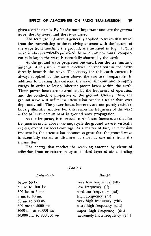
below 30 kc 30 kc to 300 kc 300 kc to 3 me 3 me to 30 me 30 me to 300 me 300 me to 3000 me 3000 me to 30,000 me 30,000 me to 300,000 me
Table I
Range
very low frequency (vlf) low frequency (If) medium frequency (mf) high frequency (hf) very high frequency (vhf) ultra high frequency (uh£) super high frequency (shf) extremely high frequency (ehf)

20 WAVE PROPAGATION
the earth is called the sky wave. Most of the long distance communication carried on below a frequency of 30 me is accomplished by means of this sky wave. (Sec Fig. 12.)
16. The Ionosphere
The upper regions of the earth's atmosphere absorb a large amount of radiant energy from the sun, which produces significant ionization of the air molecules. It is this region that reflects or
Fig. 11. Propagation of ground waves.
MANY WAVELENGTHS AWAY FROM POINT SOURCE, ANY SEGMENT OF WAVEFRONT IS CONSIDERED AS A PLANE WAV~
I
refracts the sky wave back to earth. Because of the variation in atmospheric properties at different altitudes, the ionosphere tends to form in layers, the properties of each layer being dependent upon the specific type of radiation reaching it from the sun and the atmospheric characteristics of a given altitude.
The mechanism by which radiation from the sun produces ionization cannot be adequately described by classical theory. In terms of modern quantum mechanics, photons1 of different energies (but all traveling at the speed of light) strike these molecules and produce a number of effects, depending upon specific photon
t Planck (18.~8-1948) introduced the idea that light was made up of elemental particles called photons or quanta; this explains numerous phenomena that could not then be justified by the classical wave theory of light. Planck stated that the energy (in ergs) contained in a photon of light was proportional to its frequency, with a constant of proportionality known as Planck's constant.
E = hf
Where: E Energy of photon in ergs. h = Planck's constant = 6.56 X I 0-27 erg sec. f = Frequency of light in cycles per second.
EFFECT OF ATMOSPHERE ON RADIO TRANSMISSION 21
energies. (Gas molecules normally exist in their lowest rotational and vibrational states.) Photons of definite kinetic energy excite the molecules to higher states of rotation and vibration, and are absorbed in the process. Other photons of different kinetic energy ionize individual atoms, and are also absorbed in the process. It is this latter phenomenon in which we are most interested.
An ionized atom, by definition, is one that has lost or gained one or more orbital electrons. Since the negative electrons and positive protons cancel each other in a neutral, un-ionized atom, the removal or gain of an electron leaves the remaining atom with a net positive or negative charge.
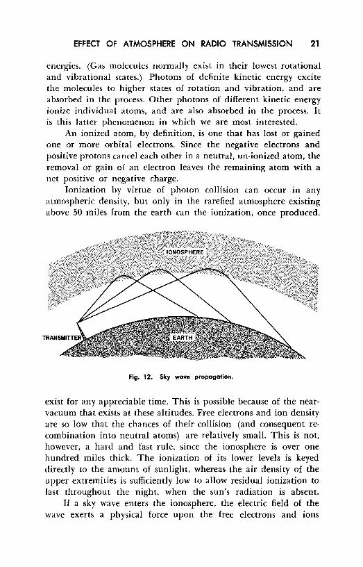
Ionization by virtue of photon collision can occur in any atmospheric density, but only in the rarefied atmosphere existing above 50 miles from the earth can the ionization, once produced,
Fig. 12. Sky wave propagation.
exist for any appreciable time. This is possible because of the nearvacuum that exists at these altitudes. Free electroris and ion density are so low that the chances of their collision (and consequent recombination into neutral atoms) are relatively small. This is not, however, a hard and fast rule, since the ionosphere is over one hundred miles thick. The ionization of its lower levels is keyed directly to the amount of sunlight, whereas the air density of the upper extremities is sufficiently low to allow residual ionization to last throughout the night, when the sun's radiation is absent.
If a sky wave enters the ionosphere, the electric field of the wave exerts a physical force upon the free electrons and ions

22 WAVE PROPAGATION
existing in this region. The amount of force may be calculated by means of equation I. The electric field of any radio wave varies sinusoidally, and therefore the force exerted will tend to make both electrons and ions oscillate sinusoidally, in unison with the applied field. Since an ion has more than 1800 times the mass of an electron, ionic movement may be neglected; only the electrons are appreciably affected by the electric field. The distance over which an unimpeded electron moves varies inversely as the frequency ol the wave; i.e., at a low frequency there is more time, and thus the electron moves a greater distance before the electric field reverses.
As mentioned previously, any accelerating charge radiates electromagnetic waves. Thus these electrons, which absorb energy when set in motion, reradiate it by virtue of that same motion. Because of a phase difference between the oscillating electron current and the original electric field, the direction of re-radiated energy is not the same as that of the incident wave. The direction is dependent upon the electron density; it always takes the path toward lower electron density. The effect is analogous to having the incident wave bent as it travels through a portion of the ionosphere. For this reason the bending of the wave is best described with optical analogies.
An electric field in the ionosphere forces the free electrons to oscillate sinusoidally. Without regard to their reradiation, these moving particles constitute an electron (or actual conductive) current - similar to the type that exists in a wire - whose magnitude is proportional to the instantaneous velocity of these electrons. The motion of the free electrons lags the applied field in phase by 90 degrees, in accordance with the laws of simple harmonic motion. This means that the electron current also lags the applied field by 90 degrees.
It should now be clear that the current flowing through a given portion of space in the ionosphere is made up of two components: the previously described space current, which leads the electric field by 90 degrees, and the electron current, which lags the electric field by 90 degrees. The two currents tend to subtract, resulting in a net reduction in the space current. The net space current flowing between any two points in a medium is directly proportional to the dielectric constant of that medium, hence any reduction in the space current is equivalent to a reduction in the dielectric constant below what it would have been had the electron

EFFECT OF ATMOSPHERE ON RADIO TRANSMISSION 23
current not been present. Since the dielectric constant for air is essentially I, it follows that it is less than l in the ionosphere, where there is an electron current. The extent of the reduction is principally dependent upon the electron density.
The optical analogy may now be introduced, because the refractive index of any portion of the ionosphere is equal to the square root of its dielectric constant; that is,
n=yk
Where: n = refractive index Where: k = dielectric constant
(5)
Moreover, the phase velocity of any wave is inversely proportional to the refractive index. That is, phase velocity = c/n where c is the velocity of light in a vacuum. Putting equation 5 in reciprocal form we have:
1 1
"=v"°k (6)
Multiplying both sides of the equation by c, the velocity of light in a vacuum:
C C
n y7c (7)
But c/n is equal to the phase velocity, hence
phase velocity = _c_ yk
(8)
The most significant part of the above is that the wave's phase velocity will be greater as the dielectric constant is reduced. In fact, since the dielectric constant is less than I, the phase velocity will actually exceed the speed of light.
Imagine a wave front entering the ionosphere at an angle (J.
Since the top part of the wave front will enter the ionosphere first, its velocity will be greater than that of the lower part of the wave front, which has not yet entered. Under the above conditions one of two things must happen: either the wave front breaks up, or it bends in the direction shown. The latter happens, and this may be justified by using classical Huygen constructions. As the wave front continues in its penetration of the ionosphere, the top part of the wave front will always be in contact with a region

24 WAVE PROPAGATION
of higher electron density, and will thus have a greater velocity, causing a continual bending (or refraction) of the wave. The exact direction the wave takes is governed by Snell's law. (See Fig. 13~
n = s!n<f>1 ( 9) sm4>,
Where: 4>1 The angle that the direction of propagation makes with the normal to a unit volume of space in the ionosphere containing a particular electron density (labeled B). The wave front enters this unit volume of space from a different unit volume of space, containing a different electron density (labeled A).
ef>r = The angle that the wave front makes with the normal as it proceeds through this unit volume (B) of space in the ionosphere.
n = The relative index of refraction between the two unit volumes being considered (A and B).
This is shown in Fig. 12. Note that, since the ionosphere varies in electron density (becoming progressively greater as the middle is approached) , the wave continues to suffer a refraction as it progresses in the medium. If the electron density is sufficient, or the ionosphere thick enough, the wave is returned to earth as shown.
17. Layers or Regions of the Ionosphere
The term ionosphere was first applied broadly to an ionized region above the earth. Upon investigation, however, it was found that the ionosphere was split into a number of layers or regions, corresponding to altitudes where ionic density was at a maximum. Layers are formed because at different altitudes there are different atmospheric properties, and differences in the sun's radiation. As an example, the highest regions are produced principally by ultraviolet radiation. On the other hand, cosmic rays, with their greater penetrating power, are responsible for some of the lower region ionization. During sun-spot disturbances, when cosmic ray radiation is at a maximum, the lowest region is often intensely ionized, bringing about communication failure at certain frequencies.
The regions vary in ionic density and height above the earth, depending upon whether or not the area is in daylight - and, with

EFFECT OF ATMOSPHERE ON RADIO TRANSMISSION 25
some regions, depending on the time of day or night. The four principal daytime regions are called the D, E, Fl, and F2, regions, as illustrated in Fig. 14.
The lowest of these regions is the D region. It is at such a low altitude (30 to 55 miles) that the molecules, once ionized, quickly recombine because of the higher air density. For the same reason, the degree of ionization at any time is governed by the amount of sunlight. Far from being a good reflector of radio waves, the D region is responsible for most of the low frequency sky wave
Fig. 13. Angles between Incident and emerging wavefronts and the normal to adjacent volumes of different electron densities In the
Ionosphere.
INOIIMAL
I
B
attenuation. Much of the energy absorbed by the free electrons from an incident wave is lost in the form of heat through collision of these electrons with un-ionized air molecules.
The collisions may wholly or partially impede the re-radiation of the wave as it passes through the region, depending on the number of molecules present, the amount of ionization of the medium, the frequency of the incident sky wave, and the distance the wave travels through the medium. During the middle of the day, when the D region ionization is at a maximum, the effect is particularly evident.
D region absorption varies inversely as the frequency squared. It becomes an increasing deterrent to daytime communication as the frequency dips below 6 or 7 me - and absorption reaches a

26 WAVE PROPAGATION
maximum at about me. Below this frequency, D region penetration decreases, and so does the absorption.
The E region is the lowest region that is effective in returning the sky wave to earth, and thus affording long distance communication. In many respects, however, it resembles the D region. Its height (about 65 miles) is sufficient to insure that a relatively low amount of electron collision with air molecules will occur, except for periods of high ionization. Its height, however, is not sufficient
t ... :c Cl)
iii :c
NIGHT DAY
F2
IONIZATION -
Fig. 14. Variation of Ionization {electron density) for the Ionospheric layers under daytime and nighttime con-
ditions.
to allow much residual ionization. Therefore, at noon, when the ionization is most intense, E region absorption becomes pronounced.
Another important region for communication is the F2 region. The F2 region is the most prominent, and the most intensely ionized region of the ionosphere. The rarefied atmosphere at its height (150 to 250 miles) is sufficient to allow a high degree of residual ionization. The ionization is most intense at about noon; then it gradually decreases, reaching a minimum just before sunrise. Its height varies with sun-spot activity, season, and even time of day.
The F2 region often splits into two distinct regions during the day. The new region is termed the Fl region, while the original main region retains the F2 designation. The main effect that the Fl region has on sky wave communication is to introduce some additional absorption. Thus, during the night the over-all ionization of the atmosphere is lower than during the day. The Fl layer rejoins the F2 layer, making a single F2 layer; the E layer almost completely disappears.
The extent to which a given wave is refracted in the ionosphere is a function of the refractive index. The refractive index is a func-

EFFECT OF ATMOSPHERE ON RADIO TRANSMISSION 27
tion of the number of free electrons per cubic centimeter and the frequency.
Where: n N f
(10)
the index of refraction. the number of free electrons per cubic centimeter. the frequency of the sky wave in kilocycles.
From examination of the above formula, it can be seen that n must always - for all real values - be less than 1 (or zero). The ratio 81 N /f2 is the factor that determines whether the wave will be returned to earth because of refraction in a region, or whether the value will be attenuated when passing through the region. If the ratio is less than 1, n is real and the wave is refracted without significant attenuation. If the wave's angle (unless angle from normal is specified, the angle is measured with respect to the earth or the tangent to the ionosphere) of penetration in the region is low enough, and the region thick enough, the wave will be returned to earth. If the ratio is greater than one, n is imaginary and the wave is attenuated. The attenuation would be linear with distance of penetration if the layer were homogeneous. Because of the concentration of free electrons at the center, the attenuation is more exponential in nature. Attenuation under these circumstances is roughly analogous to a waveguide that is operating below the cutoff frequency - the phase velocity approaches infinity and the group velocity approaches zero.
18. Angle of Incidence
If a wave enters a region perpendicularly, there obviously can be no refraction. What does happen is that the wave will penetrate the layer until N increases to the point at which the refractive index is zero (or the ratio of 81N/f2 is I). If there is sufficient electron density within the region, or if the frequency is low enough, this value of refractive index can be achieved - and the wave is reflected and returned to earth. Of the two variables (electron density and frequency) the only one we have any control over is the frequency, and thus the highest frequency that can be returned at an incident angle of 90 degrees is called the critical frequency. If the frequency is increased above this critical value,

28 WAVE PROPAGATION
the wave can only be returned to earth if the incident angle with the tangent to the region is less than 90 degrees.
19. Critical Angle
If a wave above the critical frequency is to be returned to earth it must be radiated at a sufficiently low angle with respect to the earth's surface to insure refraction. The highest angle of radiation that permits the radio waves of a given frequency to be returned to earth by a region is called the critical angle for that region. Examples of this are shown in Fig. 15. Because radio waves
Fig. 15. The effect of the angle of radiation on sky wave transmission.
travel in an approximately straight line from the transmitter to the ionosphere, the angle of incidence to the ionosphere is 90 degrees minus the radiation angle from the transmitting antenna to the ground.
Clearly, as the frequency is increased, increased attention must be paid to the angle of radiation if penetration of the ionosphere, and subsequent loss of the signal, is to be avoided. Each region has a critical frequency and a critical angle for frequencies above the critical value. Often one region will be penetrated (because the

EFFECT OF ATMOSPHERE ON RADIO TRANSMISSION 29
sky wave may exceed either or both values) and still the signal may be refracted from a higher region, if it has sufficient electron density. This is shown in Fig. 15, where ray I is easily refracted by the E region because it enters below the E region critical
angle. Ray 3 penetrates the E region but is returned to earth by the F2 region because it is below the F2 region critical angle. Ray 4 also penetrates the E region. It enters the F2 region at its critical angle and is returned to earth. Ray 5 penetrates both regions and is lost in space. This diagram applies 'for one frequency only. It a lower frequency is used, higher critical angles for both regions are present; conversely, if the frequency is increased, both regions have lower critical angles. If the frequency is increased sufficiently, there comes a time when, even if a wave is emitted from the transmitter parallel to the earth, it will exceed the critical angle for any region. This condition is reached at about 30 me. Above it, the sky wave cannot be used for reliable communication.
20. Skip
If the critical frequency of the ionosphere has been exceeded, and hence there exists a critical angle, there is a minimum ground distance from the transmitter at which the sky wave will be returned to earth. Note that in Fig. 15 Ray 2 is incident to the E region at its critical angle. Note where the refracted wave reaches the ground. If the critical angle is exceeded, the signal is lost -yet the distance between the transmitter and the point where the sky wave returns to earth is too great for communication with the ground wave. This is a "silent" zone that encircles the transmitter from the point where the ground wave fades out to the point where the sky wave is first heard. The skip distance is denoted by the minimum terrestial distance from the transmitter to the point of sky wave return.
As the frequency is raised the skip distance increases, because of a lowering of the critical angle. For communication to a point at a certain distance from the transmitter, and at a certain time of day, and season, there exists a maximum usable frequency (abbreviated MUF) that may be used for sky wave communication. Each ionospheric region has is own MUF for communication over a given distance from the transmitter. This information is made available in chart form for commercial services.

30 WAVE PROPAGATION
21. Sporadic E Reflection
In addition to the regular E region ionization there often exists within that region a thin intensely ionized region called a sporadic E "cloud." Sporadic E clouds vary in size from one to several hundred miles across. They usually drift from place to place, and appear and disappear in a most unpredictable manner, during both day and night.
A sporadic E cloud has a rather well defined boundary, and as a rule, waves are reflected from its surface, rather than refracted. They have no critical frequency. As the frequency of a vertical wave is increased, the returning signal dissipates to a non-usable value. The clouds have no critical angle either, although again, if the sky wave is of a high enough frequency and strikes the cloud at too high an angle, little of the signal will be returned.
Because of their intense ionization, sporadic E clouds are often able to return to earth waves of much higher frequency than 30 me. If the cloud is correctly situated between transmitter and receiver, it can greatly enhance normal E region communication. Great distances have been covered on frequencies up to 50 me and higher by using sporadic E reflection. The great disadvantage inherent in this type of communication is that it is unreliable. Cloud·s appear, vary in ionization intensity and location, and then disappear with an utter lack of regularity. The source of sporadic E ionization is not fully understood.
22. Review Questions
(1) Why does the composition of the atmosphere affect wave propagation? (2) Define the three regions of the atmosphere. (3) What is the frequency range of medium frequency waves? (4) What is the primary determinant in ground wave propagation? (5) Describe the four ionized layers of the atmosphere. (6) Explain the process of ionization. (7) Define critical frequency. (8) How does the critical angle control wave reflection? (9) Define "skip"; "silent zone"; "skip distance".
(IO) What is sporadic E reflection?

Chapter 4
NORMAL TROPOSPHERIC PROPAGATION
23. Space Waves
To distinguish it from the ground wave and sky wave, propagation in the lowest region of the Earth's atmosphere is often called tropospheric propagation or s,pace wave propagation. This type of wave transmission relies on neither ground currents nor ionospheric refraction or reflection. It is the wave used in "line of sight" communication (when transmitting and receiving antennas are within sight of one another).
The space wave commonly consists of two components: the direct ray and the ground reflected ray, as illustrated in Fig. 16A. If the antennas are sufficiently close to each other, both of these rays usually reach the receiving antenna, although in different proportions. The ground reflected ray is usually the weaker of the two because of the losses suffered during reflection from the earth. The direct ray suffers about the same attenuation as a wave in free space. At the receiving antenna, the total signal is the vector sum of these two components.
The transmitting and receiving antennas are usually quite far apart in relation to their elevation above the ground, so that the length of the path of the reflected ray deviates little from that of the direct ray. The reflected wave suffers a 180-degree phase shift when it rebounds from the ground, and so (neglecting earth losses during reflection), if the two rays traveled the same distance, they would add vectorially to zero, resulting in complete cancellation at the receiving antenna.
31

32 WAVE PROPAGATION
Fortunately, the reflected ray does travel a slightly greater distance, hence the net phase difference at the receiving antenna is never 180 degrees. In this idealized case, the actual phase difference is determined purely by the path difference in terms of wavelength, not linear units. In other words, the net signal received under
(A)
(B)
Fig. 16. {A) The direct and reflected ray components of the space wave. (B) The shadow zone.
these conditions is dependent largely upon the frequency used. For example, if the wavelength of operation is 360 meters, and if the path difference is 2 meters, the phase shift away from 180 degrees would be only 2 degrees. This would still allow a 178-degree phase differential to exist between the direct and the reflected rays, resulting in almost complete cancellation at the receiving antenna. If, however, the wavelength of operation is 4 meters, the same 2 meters of path difference would produce a phase difference of 180 degrees, completely cancelling the reflective phase shift of 180 degrees. The two rays would, in this case, add algebraically at the receiving antenna and result in a signal nearly double the strength of either ray.

NORMAL TROPOSPHERIC PROPAGATION 33
It should be clear from the above that at low frequencies, the space wave is of little use because of this cancellation; only at higher frequencies where the path difference becomes a significant proportion of the wavelength used does the space wave become an important means of communication. Above 30 me, where the ground wave is quickly attenuated and the sky wave is not returned to earth, the space wave is often the only means of communication between two points.
24. The Radio Horizon
The theoretical conditions presented above are usually complicated by practical limitations. For instance, the earth is not a perfect conductor, hence some of the ground reflected signal is lost in the process of reflection. For the same reason, the phase shift of reflection is never exactly 180 degrees. In addition, the curvature of the earth causes the reflected ray to change from a plane to a divergent wave. This last factor in itself is sufficient at low grazing angles to reduce significantly the reflected signal strength at the receiving antenna. Because of these losses, the total signal at the receiver is never exactly canceled, no matter what the frequency may be. Nevertheless, practical deviations from the theoretical conditions are not great enough to invalidate the conclusions drawn from the idealized example.
To lessen the received signal's dependence upon the relative phase difference of the two rays, a beam is usually formed that concentrates most of the space wave energy in the direct way. This is the job of a well designed transmitting antenna.
As a result of the earth's curvature, there exists a definite horizon to the space wave, beyond which there exists a shadow zone that cannot be reached by the direct or the ground reflected wave (Fig. 16B). Note that in the figure the radio horizon and optical horizon are not the same. Although previously the dielectric constant of free space and the atmosphere in general were taken as one, this is not strictly so. Temperature, density, pressure, and water vapor content of the air lessen as altitude is increased. This has an effect similar to that of ionospheric free electrons; i.e., the dielectric constant is reduced with an increase of altitude. If individual rays of a plane wave travel at different altitudes (as they usually do), the higher ones will travel faster, and the wave will be
34 WAVE PROPAGATION
refracted slightly towards the earth. The bending will vary with weather conditions and will become more pronounced as the rate of change with an increase in altitude of these atmospheric parameters increases.
25. Antenna Height
It is often important to know just how far a transmitting and receiving antenna can be separated without going below the radio horizon. A simple relationship exists between the distances of separation and the height of both antennas.
(12)
Where: D Distance in miles between receiving and transmit-ting antenna.
Hr = Height in feet of receiving antenna. Ht = Height in feet of transmitting antenna
The distance from the transmitting antenna to the radio horizon can be derived by considering the radical containing Ht.
D (to horizon) = ~ = -../"2 yJ:f; = 1.41 v'1Ii" (13)
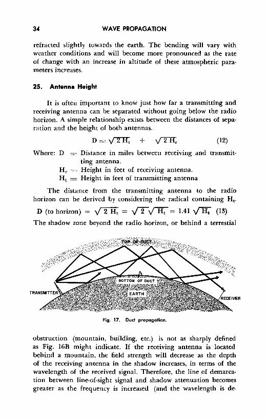
The shadow zone beyond the radio horizon, or behind a terrestial
Fig. 17. Duct propagation.
obstruction (mountain, building, etc.) is not as sharply defined as Fig. 16B might indicate. If the receiving antenna is located behind a mountain, the field strength will decrease as the depth of the receiving antenna in the shadow increases, in terms of the wavelength of the received signal. Therefore, the line of demarcation between line-of-sight signal and shadow attenuation becomes greater as the frequency is increased (and the wavelength is de-

NORMAL TROPOSPHERIC PROPAGATION 3S
creased) . The effect is clearly seen in the difference in shadow zone signal strength between television Channel 13 (210-216 me) and Channel 2 (54-60 me) .
In many cases, if the terrain is rough in line-of-sight communication, the received signal strength is actually greater than it would be if the terrain were flat. This is because the rough ground scatters and partially blocks the ground reflected ray, thus avoiding phase cancellation. Even in the shadow zone, the signal strength is largely affected by the roughness of the earth. The roughness causes a diffraction of the wave down into the shadow zone. This is such an important contribution to shadow zone signal that the shadow zone is often called the diffraction zone.
26. Duct Propagations
Often there is an abnormal vanauon in atmospheric conditions that has a great effect on the propagation of the space wave. Sometimes the moisture content of the air near the ground is great, but decreases rapidly with an increase in altitude. This change is usually accompanied by marked temperature variations. The effect on the dielectric constant of the air is the creation of a welldefined boundary in which the rate of change of the dielectric constant is very great with a slight increase in altitude. This dielectric boundary and the earth form the upper and lower walls of an atmospheric duct. Waves originating in this duct and traveling approximately horizontally are trapped, and are propagated around the curvature of the earth in a series of jumps involving earth reflection and dielectric boundary reflection. (See Fig. 17.) When this happens, one can no longer thing of space wave propagation in terms of line-of-sight and shadow zone concepts, for under these conditions, radio waves are often propagated hundreds of miles into the shadow zone.
The action of an atmospheric duct is analogous to a metallic waveguide: there is a definite minimum frequency that may be propagated in the duct, depending on the distance between the two boundaries. The width of such ducts varies from a few feet to a few hundred feet, so that the lowest usable frequency may vary from a high of several thousand megacycles to a low of 50 to 100 me.
Many interrelated factors contribute to the effectiveness of duct transmission. For example, the receiving and transmitting antennas must be located within the duct. In some instances this may mean
36 WAVE PROPAGATION
the difference of a few feet. If the receiving antenna is located outside the duct boundaries, no signal will be received, even though it may be quite strong within the duct.
27. Duct Variations
In addition to ducts found over the land which vary in height from approximately 100 to over 1500 feet, there is also a duct formed over the ocean about 50 feet from the water surface. Its vertical dimension is very small compared to the land ducts; thus, it is an almost useless waveguide for the lower frequencies, becoming important only for transmissions at frequencies well over 1000 me. For these very high frequencies, the transmitted energy may be carried over relatively long distances through this narrow duct.
There are a large number of varieties of atmospheric ducts. Some of these actually focus signals when the frequency is right, while in most cases the duct behaves as a simple waveguide. Ducts may be helpful in transmission for some frequencies but may wash out other radio paths altogether. Add to this the fact that a sudden wind may destroy the efficacy of a duct that has been in existence for a long period before and it is understandable why duct propagation is inconsistent and unreliable.
Temperature inversions (a condition in which layers form so that the temperature is abnormally high in the upper regions and abnormally low in the lower regions) are more or less common occurrences particularly in coastal areas. Air from the land areas, usually comparatively hot and dry, passes over the cool, moist ocean air, forming the so-called inversion layers. The ducts formed thereby result in excellent signal transmission at frequencies from 100 me to 1000 me over paths of l 00 miles or more.
28. Review Questions
(I) What is meant by "space wave" propagation? (2) Why are space waves of little use at low frequencies? (3) What effect does the curvature of the earth have upon the reflected ray. (4) Explain the importance and meaning of the diffraction zone. (5) Whal is an atmospheric <lucl? (6) Why may <lucl propagation be inconsislelll and unreliable? (7) What is temperature inversion? (8) What frequencies normally give good results for duct transmissions? (9) Of what use arc "inversion layers"?

Chapter 5
SCATTER PROPAGATION
29. Introduction
Until quite recently, very high frequency waves have not been used in communications that involved distances in excess of line• of-sight path lengths. The vhf and uh£ spectra exceed the critical frequency, hence these waves are not refracted in the ionosphere, but escape into space. Thus vhf and uh£ waves are normally propagated as space waves.
Observations made during the last war showed, however, that uh£ signals sometimes were propagated over distances considerably in excess of line-of-sight; that is, occasionally signals from highpower radar sets were easily detectable well beyond the horizon with losses only slightly greater than they suffered in free space. For the most part, these phenomena were attributed to and could be satisfactorily explained by ducting and superrefraction processes in the troposphere, in addition to diffraction effects. As research continued after World War II, however, it became apparent that the distances over which consistent rather than occasional propagation of usable signals occurred were far greater than smooth-sphere diffraction could explain, even with the help of ducts and superrefraction.
In general, attenuation measurements made by research workers demonstrated the complete inadequacy of former theories in accounting for strong beyond-the-horizon (sometimes called transhorizon) transmissions.
37

38 WAVE PROPAGATION
Many theories have been proposed to explain this phenomenon; although they differ substantially from each other in detail, in general the propagation is attributed to minute disturbances in the electrical properties of the troposphere. Precise measurements have shown that appreciable variations in the dielectric constant of the atmosphere are present as a result of turbulence, stratification and other more obscure effects, and that these variations are of the order needed to produce the observed propagation. Figure 18 illustrates the differences between distances covered by 3000-mc
II.I 0
f (I)
311
20
40
60
9 80 II.I m m Q
100
12010 20
"'" \ ~ OBSERVED SIGNAL LEVEL
\ '
'"
~-PREDICTED SIGNAL LEVEL
100
MILES
~
200 !100 1000
Fig. 18. Curves showing the difference between the signal level at 3000 me predicted by the smooth-sphere diffraction theory and that actually observed.
waves at specific attenuations and the predicted distances that should have been covered if the propagation followed the calculations based upon smooth-sphere diffraction theory.
30. Fading
The signal reaching a receiving antenna in any kind of radio transmission often exhibits a variation with time as a result of changes in the propagation medium. This effect, called fading, is

SCATTER PROPAGATION 39
evidently due to a varying instantaneous transmission loss over the radio path.
These variations in received signal intensity are conveniently classified as either the long-term type or the short-term type of fading. The long-term variations are attributed to slow changes in ionospheric absorption and, in some cases, to gradual changes in tropospheric turbulence. The short-term variations, on the other hand, are due to phase interference that occurs among two or more simultaneous modes of propagation from the same source. The received field is made up of several components that travel over paths which often differ by several wavelengths, and it is the interference between these different modes which gives rise to so-called fast fadinf!
For any given carrier frequency, the short-term type of fading is usually studied on the basis of two sub-classifications: (1) fading rates of IO minutes to one hour, and (2) fading rates of one to IO cycles per second. The signal attenuation for the first type is primarily dependent upon the weather, time of day, and the season, while in the second case the carrier frequency is the principal factor. Accurate knowledge of the determinants of the kind of fading described in (1) is very important to the design and planning of a scatter transhorizon communication system. Many research programs have been completed recently, and many more are still in progress over the nation, to establish statistical data which will help determine the losses in transmission field strength which have to he overcome to achieve specified reliability.
Very rapid fading as described in (2) is often attributable to fast fluctuations in the dielectric constant of the troposphere as well as to possible phase interference. The graph given in Fig. 19 indicates the speed and amplitude possible in this type of shortterm signal fluctuation over a 180-mile scatter path at a frequency of approximately 400 me.
31. Path Geometry
Figure 20 shows in somewhat exaggerated form the path geometry of a typical scatter circuit at a frequency in the range from 300 me to 5000 me. As explained previously, the mechanism of tropospheric scattering appears to be a function of heterogeneities in the dielectric constant of the air due to variations of moisture,

40 WAVE PROPAGATION
temperature, and air density. Even though the attenuation of the signals may average about 70 db more than that of free space, the received signal field strengths are still substantially in excess of those which are predicted by earth diffraction effects alone.
The successful utilization of a path of this nature for communication over distances of 200 miles or more beyond the horizon calls for specialized equipment. High gain antennas, high-power transmitters, and space-diversity reception are now being employed in such communications circuits. Although the cost of such equip-
"' ,.J ILi m <.> ILi 0
60~--~--~---~----,-----,-----,
5Qt-----+-----+---+-----+---+-----I
401-----+-----l---+-----+---+-----i
101-----+-----l---+-----+---+------i
0.5 LO 1.5 2.0 2.5 3.0
Tl ME (SECONDS)
Fig. 19. Graph showing fast fading over a 180-mile scatter path at 400 me.
ment normally exceeds that of standard transmitting gear by a considerable amount, its use is justified in most cases because it reduces the number of repeater stations required.
In discussing the path geometry of scatter transmission, the question of the effects of wave polarization frequently arises. Ac-

SCATTER PROPAGATION 41
curate data on this subject are not available at the present time. Qualitative observations have demonstrated, however, that very little difference exists in transmission efficiency between vertically, horizontally, and circularly polarized waves. In addition, preliminary measurements indicate that the plane of polarization established at the transmitter is fully preserved over the scatter path and that the wave arrives at the receiver in virtually the same plane.
32. Antenna for VHF Scatter Circuits
Most of the antennas now in use are simple, center-fed circular paraboloids of revolution of various diameters. Large 60-foot-diameter arrays weighing about 6000 pounds are in common use; smaller antennas measuring about 28 feet in diameter are
TRANSMITlERANTENNA
Fig. 20. Wave scattering.
SCATTER ZONE
-RECEIVER ANTENNA
usually raised well above the ground to realize some additional gain, and are often equipped with adjustments for azimuth. Fabricated of welded aluminum tubing, these antennas are capable of withstanding winds up to 100 mph even when coated with ice.
The high cost of these arrays makes it almost mandatory that they be used for simultaneous transmission and reception - a system known as diplexing. Since there is a great difference in the amplitude levels of the received and transmitted signals - some• times in the order of 200 db - diplexing is not easily accomplished. The transmitted signal having the same frequency as the one to

42 WAVE PROPAGATION
be received must be attenuated well below the minimum detectable signal and the transmitter itself must be carefully isolated from the receiver to prevent overloading.
33. Space Diversity Reception
The technique of diversity reception relies upon the fact that when a signal has faded to a low value on one antenna, it is quite
ANTENNA A ANTENNA B
~7 " 7
RECEIVER A RECEIVER B
COMPARISON CONTROL
ELECTRONIC
I SWITCH
I -- I -
./ --
OUTPUT
Fig. 21. Switching diversity.
probable that it will have increased in strength on another antenna situated some distance from the first.
Two methods have been used successfully for choosing the antenna that provides the best response automatically; one is called switching diversity and the other combination diversity. Either of the systems may be applied to dual, triple, or quadruple antenna arrays.

SCATTER PROPAGATION 43
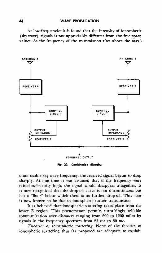
Switching diversity utilizes as many receivers as there are antennas, a comparison control circuit, and an electronic switch, as shown in Fig. 21. In this dual antenna system, the signals are demodulated and amplified in individual receivers and then are fed to the comparison-control circuit. The latter compares the signalto-noise ratio of the received material, automatically throwing the electronic switch to the positon that provides the best output. Switching may be accomplished either before or after demodulation; the former is usually preferred because the transients produced by the switching devices are seldom as large in this case.
With switching diversity the poorer signal is completely rejected while the better is totally received. This does not always result in the best possible output since, as is often the case, a combination of the better aspects of the two signals would result in an improved signal-to-noise ratio. This is the idea behind combination diversity.
In combination diversity two or more receiver outputs may be connected in parallel. A control circuit is arranged to vary the output impedance of each receiver in such a manner that the impedance is roughly inversely proportional to the signal-to-noise ratio. Thus, as the signal-to-noise ratio improves as a result of fading effects, the impedance drops and the output of that particular receiver increases. If, at the same time, the second receiver displays a poor ratio, its impedance rises and its output falls oft. The total output signal is, therefore, a combination of the best efforts of both receivers. If we add to this the fact that combination diversity reception does not suffer from switching transients, the growing popularity of this system becomes more understandable. (See Fig. 22.)
34. Ionospheric Scattering
All of the preceding material in this chapter has dealt with tropospheric scattering of uhf and vhf radio signals. During 1950, discussions carried on among experimental scientists interested in scatter propagation in the troposphere caused certain speculations, which ultimately led to the discovery that scatter effects also occur in the ionosphere. Two distinct and separate fields of investigation have thus grown almost simultaneously, causing some confusion among readers. It is important to note carefully the differences in nature, range, and limitations of the two phenomena.
WAVE PROPAGATION
At low frequencies it is found that the intensity of ionospheric (sky wave) signals is not appreciably different from the free space values. As the frequency of the transmission rises above the maxi-
ANTENNA A
RECEIVER A
CONTROL Cl RCUIT
OUTPUT IMPEDANCE
RECEIVER A
COMBINED OUTPUT
CONTROL CIRCUIT
ANTENNA B
RECEIVER B
OUTPUT IMPEDANCE
RECEIVER B
Fig. 22. Combination diversity.
mum usable sky-wave frequency, the received signal begins to drop sharply. At one time it was assumed that if the frequency were raised sufficiently high, the signal would disappear altogether. It is now recognized that the drop-off curve is not discontinuous but has a "floor" below which there is no further drop-off. This floor is now known to be due to ionospheric scatter transmission.
It is believed that ionospheric scattering takes place from the lower E region. This phenomenon permits surprisingly reliable communication over distances ranging from 600 to 1200 miles by signals in the frequency spectrum from 25 me to 60 me.
Theories of ionospheric scattering. None of the theories of ionospheric scattering thus far proposed are adequate to explain
SCATTER PROPAGATION 45
all of the peculiarities of this method of propagation, although they have been of some assistance in many respects.
Turb·ulence theory. Many of the observed phenomena involving this type of scattering may be explained by predicating a homogeneous turbulence of the ionization gradient of the lower E region. Pressure fluctuations in a uniform gas, such as the atmosphere, accompanied by temperature variations at different altitudes, give rise to density fluctuations. This, in turn, results in electron density fluctuations called blob-s of turbulence, in which aerodynamic cau.ses are responsible for the variations in ionization intensity. This theory seems to give the most complete explanation of observed phenomena.
Partial reflection theory. Some theorists hold to the belief that partial reflection from an ionospheric boundary region whose electrical density changes with height is enough to account for ionospheric scattering. Experimental workers in the field have found, however, that this theory can _be successfully applied to observed results only if certain additional assumptions are made. These assumptions involve changing irregularities in the ionization gradient, conditions which partially invalidate the "smooth" boundary reflection idea.
Meteor trail theory. It is believed by some that meteors moving through clouds of cosmic dust in the lower E region can produce non-homogeneous ionization, which partially or wholly accounts for ionospheric scattering.
The signals received by this type of scattering are exceedingly complex; their nature may often be largely attributed to scattering from meteor trails. Yet their very complexity indicates that a single cause is improbable and that much experimental work remains to be done. Such work is expected to lead to a satisfactory integration of all of the worthwhile theories to provide an adequate explanation of all the observed phenomena.
35. Review Questions
(1) What is meant by fading? (2) What explanations have been advanced for: long term fading? Short
term fading? (3) Describe and explain the essential elements of scatter transmission, (4) Illustrate, by diagram, the path geometry of a typical scatter circuit at
a frequency in the range from 300 me to 5000 me.

46 WAVE PROPAGATION
(5) What is meant by "diplexing"? (6) Draw a diagram that illustrates switching diversity. (7) Explain the function of the comparison control in the diagram required
for question 6. (8) Describe and illustrate a combination diversity system. (9) Give the essentials of the "turbulence" theory.
(IO) Explain briefly the partial reflection theory; the meteor trail theory.

Chapter 6
SPECIAL IONOSPHERIC EFFECTS AT VHF AND UHF
36. Introduction
In Chapter 3, the general behavior of radio waves of various frequencies in the ionosphere was described and explained in the light of the most recent studies in the field. Investigations of peculiar and anomalous propagation of vhf and uh£ signals are being carried on continuously throughout the world and are bring• ing to light some rather remarkable phenomena. This chapter is concerned with those effects, other than forward scattering in the ionosphere, which promise to influence the operation of long-range uhf and vhf communications circuits, radar systems, radio astronomy, and radio navigational systems.
37. The Effect of the Aurora Borealis
The aurora borealis, long a scientific mystery, is now believed to be the visual effect of varying ionization in the upper atmosphere. The apparent correlation between the appearance of the aurora and the occurrence of radar echoes has been under investigation for some time. It now appears that the visual aurora does produce scattering and reflection of radar signals under certain conditions: if the aurora is at a low elevation, the correlation is very significant. Little success has been realized in attempting to obtain radar echoes from high elevation aurora.
47

48 WAVE PROPAGATION
This effect, known as azimuthal aspect sens1tiv1ty, has been measured as precisely as possible; signals in the order of I 00 me show no echoes when the elevation is greater than 15 degrees with respect to the radar antenna, while lower frequency signals in the region of 30 me exhibit little echo effect when the angle is greater than 20 degrees. In addition to the azimuthal effect, the studies have demonstrated that echoes are much stronger with the antenna oriented toward the north - even in the most northerly countries, such as Norway - than when the echo search is made toward the south. Thus, auroral ionization by echo methods is most readily detected when the radar is directed toward the magnetic north pole at low angles of elevation. The agreement among many of the workers is that radar echoes are due to scattering from ionized :treas aligned along the earth's magnetic lines of force.
The strength of radar echoes from the aurora has been shown to depend upon the time of day and upon the season of the year. Very little echoing is observable during the noon hours with maxima occurring around midnight; although the data presently available from various sources are not sufficient for precise estimates, it is quite definite that the strongest radar echoes are obtained at the time of the year when the visual aurora are usually brightest; that is, during the equinoctial months.
38. The Effect of Meteors upon Wave Propagation
When a meteor flashes into the upper layers of the air it forms an ionized trail about two miles in length. Under special conditions, this trail is capable of reflecting a large enough proportion of the incident radio energy to make it detectable by radio means. Early investigations into short-lived bursts of reflected energy within the normal skip zone showed that these transient echoes were of meteor-trail origin.
It is fairly well established that these trails are markedly aspect sensitive. This term is used to indicate a condition in which the angle of incidence of the radio waves at the reflective boundary is an important factor in determining the strength of the returned signals. In the case of a radar system, the close proximity of the transmitter and receiver establishes a perpendicular aspect sensitivity; the strongest meteor-trail reflection occurs when the radar waves are incident on the trail at an angle of 90 degrees (Fig. 23) . For a communications application in which there is a

SPECIAL IONOSPHERIC EFFECTS AT VHF AND UHF 49
large distance between the transmitter and receiver, the angle of incidence must equal the angle of reflection toward the receiver.
Meteor trails are predominantly found between (approximately) 37 miles and 50 miles above the surface of the earth, the
INCIDENT ANGLE•90°
TRANSMITTED-SIGNAL -RECEIVED
SIGNAL
-RADAR ANTENNA
I I TRANSMITTER RECEIVER
(A)
" (B)
A ....... ., .. Fig. 23. Reflection from a meteor trail; (A) as obtained with radar equipment.
(B) As used in communications.
greatest occurrence being at about 43 miles. Echoes are of short duration, usually of the order of a half-second. During certain

50 WAVE PROPAGATION
meteor showers, specifically the Perseid meteors, the echo duration may be extended to as much as 20 seconds. It has been found that the echoes may often be analyzed to determine the velocity of the meteor quite precisely; much study has yet to be done in this field, however, before the technique is well enough developed for general astronomical purposes.
39. The Faraday Effect
The first radar moon echoes obtained in 1946 by the U. S. Army marked the beginning of many such attempts, most of which have been successful. Most workers report two distinct types of fading. (1) One type of fading, having a period of a few seconds, is attributed to the libration (an oscillatory motion, like that of a balance) of the moon itself. (2) The second type, with a period of approximately one hour, is most intense a few hours after sunrise. This points to ionospheric effects. On the other hand, there is some evidence that it is due to the so-called "Faraday Effect," in which the plane of polarization 0f a wave is rotated in the presence of the earth's magnetic field. Verification of this theory has been reported recently; transmitters using perpendicularly oriented dipoles have received moon echoes with fading periods that agree closely with those predicted by the theory.
40. Ionospheric Absorption of Radio Waves
The refractive effect of the ionosphere has been discussed in previous chapters and has been shown to result from the variations in electrical density in the successive regions of this portion of the atmosphere. A second phenomenon involves energy losses as a radio wave passes into the ionosphere. Basic theory of transmission through ionized air predicts that very little loss will take place in the uh£ region in this manner. Since there has been insufficient experimentation at the ultra high frequencies, the evidence uncovered in tests with normal high frequencies has been extrapolated to the uhf range by some authorities. These conclusions are summarized below.
The ionosphere contains "free" electrons. As the field of the passing wave acts upon these electrons, they move about in response to the alternations of polarity, the amplitude of the oscillation depending directly upon the strength of the field and inversely

SPECIAL IONOSPHERIC EFFECTS AT VHF AND UHF 51
upon the mass of the particle. Such oscillation results in re-radiation of energy at the same frequency, so that very little of the total energy of the wave is lost; The conversion from field to kinetic and back to field energy is quite efficient. In other words, the fact that oscillation occurs does not account, in itself, for ionospheric absorption.
The only charged particles in the ionosphere that are involved in this process are the electrons; positive ions are not affected because of their relatively great inertial mass, a characteristic which insures that they will remain quiescent even when immersed in an alternating field. Oscillating electrons can, however, collide with neighboring gas molecules and positive ions, their kinetic energy being sufficient to set the latter in motion. This conversion does produce a net field loss, since a part of the field energy is converted into kinetic energy of massive particles (i.e., into heat) . Thus, the degree of absorption is determined to a great extent by the frequency of these electron-molecule-ion collisions.
Experimental evidence points to the D region of the ionosphere as the site of the absorptive action. At low and middle latitudes of the Earth, the degree and time of occurrence are largely under solar control; at high latitudes, localized effects are associated with auroral, magnetic, and ionospheric disturbances, rather than with the sun. Although it is still the prevailing view that streams of charged particles originating in the sun are responsible for most of the 0- layer ionization, the details of the mechanism are still far from clear.
41. Effect of the Ionosphere on Radio Waves of Extra-Terrestrial Origin.
Although most of the interest in ionospheric effects centers around communications circuits using the uh£ range, the comparatively new science of radio astronomy is very much concerned with signals of extra-terrestrial origin. Radio astronomy shows great future promise, not only as a supplement to optical astronomy, but as a field in itself. For this reason, the effect of the ionosphere on the so-called "Janssen signals" from space is of prime importance in that it makes necessary the correction of coordinates of "radio stars" as observed on radio telescopes.
Ionospheric refraction. The signals from radio stars have been found to deviate to a greater degree than that predicted by standard

52 WAVE PROPAGATION
ionospheric refractive theory. Much theoretical work has been carried on in recent years to help explain the discrepancies between the predicted and the experimemal radio paths. Theories based upon increasing curvature of the upper F2 region and upon greatly increased electron density in the ionosphere during the summer, particularly in the layer of the F2 region immediately above the point of maximum ionization, are currently under investigation.
"Twinkling" or radio stars. The radio signal stream from localized regions in outer space is by no means constant in intensity. These rapid and unpredictable variations - now commonly referred to as scintillation or twinkling - were once thought to be inherent in the sources themselves. Later work by separated group5 of observers demonstrated that the scintillations observed from various points 011 the earth simultaneously could not be correlated with each other. In this sense, the radio observations are similar to optical twinkling - an effect due to the earth's atmosphere. In the radio case, . however, the disturbance originates in the ionosphere rather than the troposphere.
The anticipated results of proposed experiments on radio star scintillation may be summarized somewhat as follows: scintillations will begin to appear when the received frequency falls below about 3000 me, the intensity depending upon the angle of elevation of the source above the horizon and the latitude of the observer. As the frequency is decreased below 100 me, the deviation from standard received intensity may be as much as 50 percent at low angles of elevation, the intensity falling to a minimum as the source reaches the zenith (directly overhead). Also, scintillation effects will be more pronounced at high latitudes, because ionospheric disturbances are of greater intensity in the polar regions.
42. Review Questions
(I) Under what conditions does the aurora borealis influence transmission? (2) Explain "azimuthal aspect sensitivity." (3) What is meant hy "aspect sensitive" in relationship to meteors? (4) What are the two types of fading associated with the "Faraday Effect"? (5) List the pertinent conclusions that have been drawn with respect to the
ionosphereic absorption of radio waves; to ionospheric refraction; to "twinkling" of radio stars.

INDEX
angle of incidence 27, 28 antenna height, 34, 35 aurora borealis effect, 47, 48 average level, I azimuthal aspect sensitivity, 48 boundary, 15 cosmic rays, 24, 29, !H, 32 crest level, 3 crests, 3 critical angle, 28, 29, 30 diffraction zone, 35 direct ray, 31 displacement current, 7 diversity reception, 42, 43 diversity switching, 42, 43 D region, 25, 26, 51 duct propagation, 35, 36 E field, 9, 10 E region, 25, 26, 29, 30 electric field, 5, 6, 7, 8, 9, 10, 21, 22 electromagnetic waves, 7, 8, 9, 10 Fl region, 25, 26 F2 region, 25, 26, 29, 52 fading, 38, 39, 50 Faraday effect, 50 frequency, 4, 19 frequency range table, 19 ground currents, 31 ground wave, 19, 29 ground wave propagation, 12, 13 H field, 10 Huygen constructions, 23 ionization, 20, 21, 22 ionized atom, 21 ionosphere, 18, 20, 21, 22
layers of, 24, 25, 26, 27, 28
55
ionospheric absorption, 50, 51 ionospheric refraction, 31, 5 l, 52 ionospheric scattering, 43, 44, 45 inversion layers, 36 line of sight communication, 31 magnetic field, 7 meteor effect, 48, 49, 50 meteor trail theory, 45 MUF, 29 partial reflection theory, 45 path geometry, 39, 40, 41 phase velocity, 23 photons, 20, 21 photon collision, 21 Planck's constant, 20 polarization, l, 9 propagation, 1 radiation, 4, 5, 6, 7 radio horizon, 33, 34, 35 ray, 8, 9 reflected rays, 31, 32, 33 reflected wav~. 31 refractive index, 23, 24, 26, 27 relative phase shift, 33 selective fading, 13 shadow zone, 33, 35 silent zone, 29 sky wave, 19, 20, 29 skywave propagation, 12, 13 Snell's law, 24 space current, 7, 22 space wave propagation, 31 space waves, 19, 31, 32, 33 sporadic E clouds, 30 sporadic E reflection, 30 stratosphere, l 8

56
sunspot cycle, 1 trans-horizon transmissions, 37 troposphere, 18 tropospheric propagation, 31 tropospheric scattering, 39, 43 turbulence, 38 turbulence theory, 45 twinkling of radio stars, 52 vertical electrical field, IO vertical polarization, 19
INDEX
vertically polarized wave, 10 Vlff scatter circuits antenna, 41, 42 wave amplitude, 3 wave diffraction, 16, 17 wave front, 8, 9, 10, 23 wave length, 3, 4, 5 wave motion, 2, 3, 4 wave reflection, 14, 15, 16 wave types, 18, 19, 20 wave refraction, 15, 16, 17