Embed Size (px)
Citation preview
Waveguides
Waveguides, like transmission lines, are structures used to guideelectromagnetic waves from point to point. However, the fundamentalcharacteristics of waveguide and transmission line waves (modes) are quitedifferent. The differences in these modes result from the basic differencesin geometry for a transmission line and a waveguide.
Transmission line
• Two or more conductorsseparated by some insulatingmedium (two-wire, coaxial,microstrip, etc.).
• Normal operating mode is theTEM or quasi-TEM mode (cansupport TE and TM modes butthese modes are typicallyundesirable).
• No cutoff frequency for the TEMmode.
• Significant signal attenuation athigh frequencies due toconductor and dielectric losses.
Waveguide
� Typically one enclosed conductorfilled with an insulating medium(rectangular, circular, etc.).
� Operating modes are TE or TMmodes (cannot support a TEMmode).
� Must operate the waveguide at afrequency above the respectiveTE or TM mode cutoff frequencyfor that mode to propagate.
� Lower signal attenuation at highfrequencies than transmissionlines.
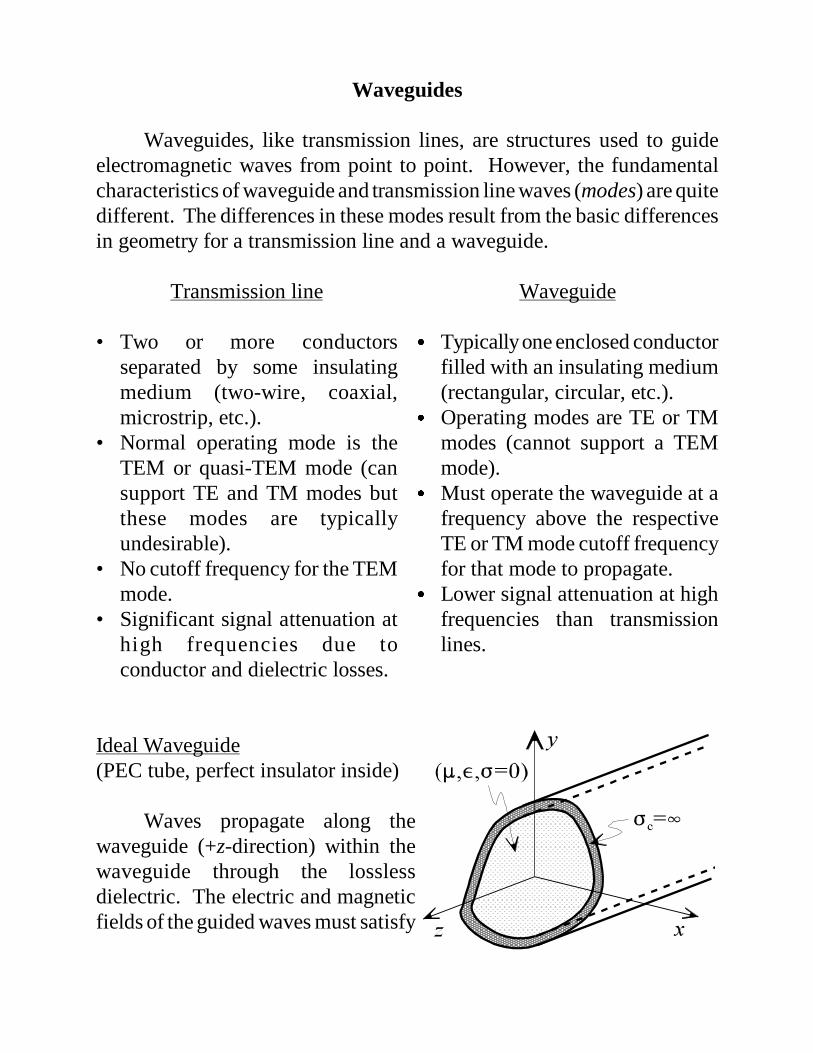
Ideal Waveguide(PEC tube, perfect insulator inside)
Waves propagate along thewaveguide (+z-direction) within thewaveguide through the losslessdielectric. The electric and magneticfields of the guided waves must satisfy

the source-free Maxwell’s equations.
Assumptions:(1) the waveguide is infinitely long, oriented along the z-axis,
and uniform along its length.(2) the waveguide is constructed from ideal materials (enclosing
PEC conductor is filled with a perfect insulator).(3) fields are time-harmonic.
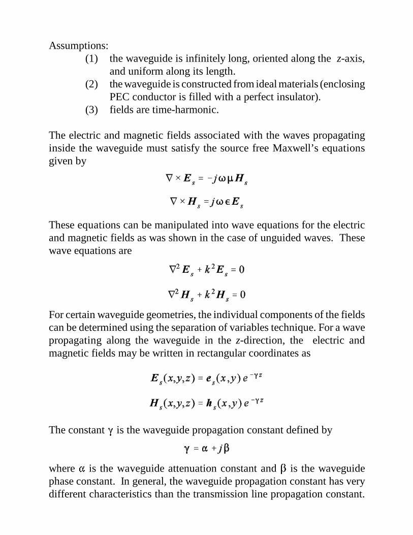
The electric and magnetic fields associated with the waves propagatinginside the waveguide must satisfy the source free Maxwell’s equationsgiven by
These equations can be manipulated into wave equations for the electricand magnetic fields as was shown in the case of unguided waves. Thesewave equations are
For certain waveguide geometries, the individual components of the fieldscan be determined using the separation of variables technique. For a wavepropagating along the waveguide in the z-direction, the electric andmagnetic fields may be written in rectangular coordinates as
The constant � is the waveguide propagation constant defined by
where � is the waveguide attenuation constant and � is the waveguidephase constant. In general, the waveguide propagation constant has verydifferent characteristics than the transmission line propagation constant.
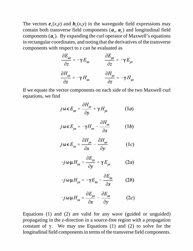
The vectors es (x,y) and hs (x,y) in the waveguide field expressions maycontain both transverse field components (ax, ay ) and longitudinal fieldcomponents (az). By expanding the curl operator of Maxwell’s equationsin rectangular coordinates, and noting that the derivatives of the transversecomponents with respect to z can be evaluated as
If we equate the vector components on each side of the two Maxwell curlequations, we find
Equations (1) and (2) are valid for any wave (guided or unguided)propagating in the z-direction in a source-free region with a propagationconstant of �. We may use Equations (1) and (2) to solve for thelongitudinal field components in terms of the transverse field components.
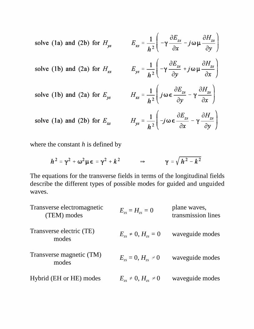
where the constant h is defined by
The equations for the transverse fields in terms of the longitudinal fieldsdescribe the different types of possible modes for guided and unguidedwaves.
Transverse electromagnetic Ezs = Hzs = 0 plane waves, (TEM) modes transmission lines
Transverse electric (TE) Ezs � 0, Hzs = 0 waveguide modes modes
Transverse magnetic (TM) Ezs = 0, Hzs � 0 waveguide modes modes
Hybrid (EH or HE) modes Ezs � 0, Hzs � 0 waveguide modes
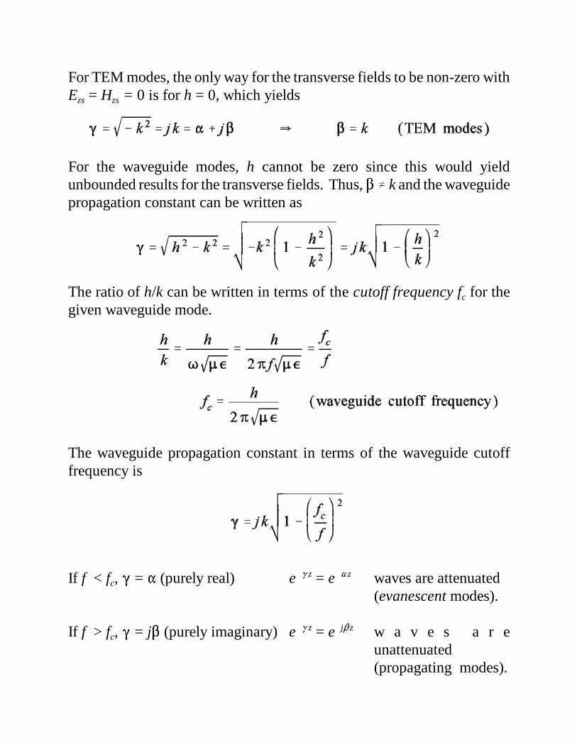
For TEM modes, the only way for the transverse fields to be non-zero withEzs = Hzs = 0 is for h = 0, which yields
For the waveguide modes, h cannot be zero since this would yieldunbounded results for the transverse fields. Thus, � � k and the waveguidepropagation constant can be written as
The ratio of h/k can be written in terms of the cutoff frequency fc for thegiven waveguide mode.
The waveguide propagation constant in terms of the waveguide cutofffrequency is
If f < fc, � = � (purely real) e�� z = e�� z waves are attenuated(evanescent modes).
If f > fc, � = j� (purely imaginary) e�� z = e�j� z w a v e s a r eunattenuated(propagating modes).
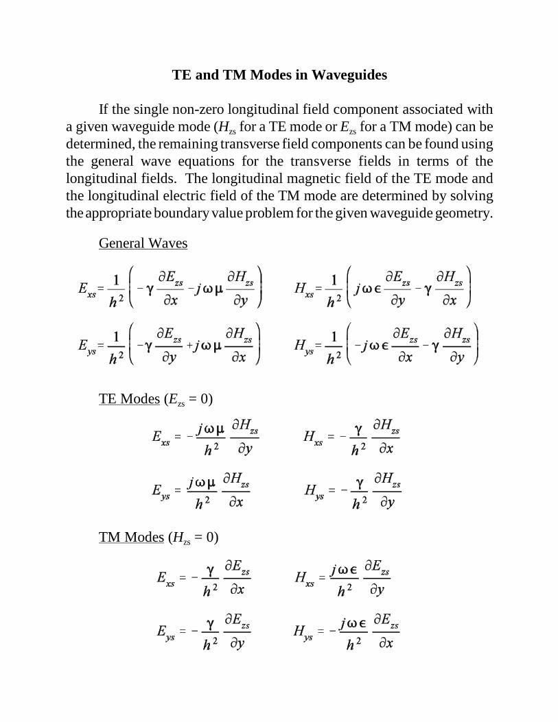
TE and TM Modes in Waveguides
If the single non-zero longitudinal field component associated witha given waveguide mode (Hzs for a TE mode or Ezs for a TM mode) can bedetermined, the remaining transverse field components can be found usingthe general wave equations for the transverse fields in terms of thelongitudinal fields. The longitudinal magnetic field of the TE mode andthe longitudinal electric field of the TM mode are determined by solvingthe appropriate boundary value problem for the given waveguide geometry.
General Waves
TE Modes (Ezs = 0)
TM Modes (Hzs = 0)
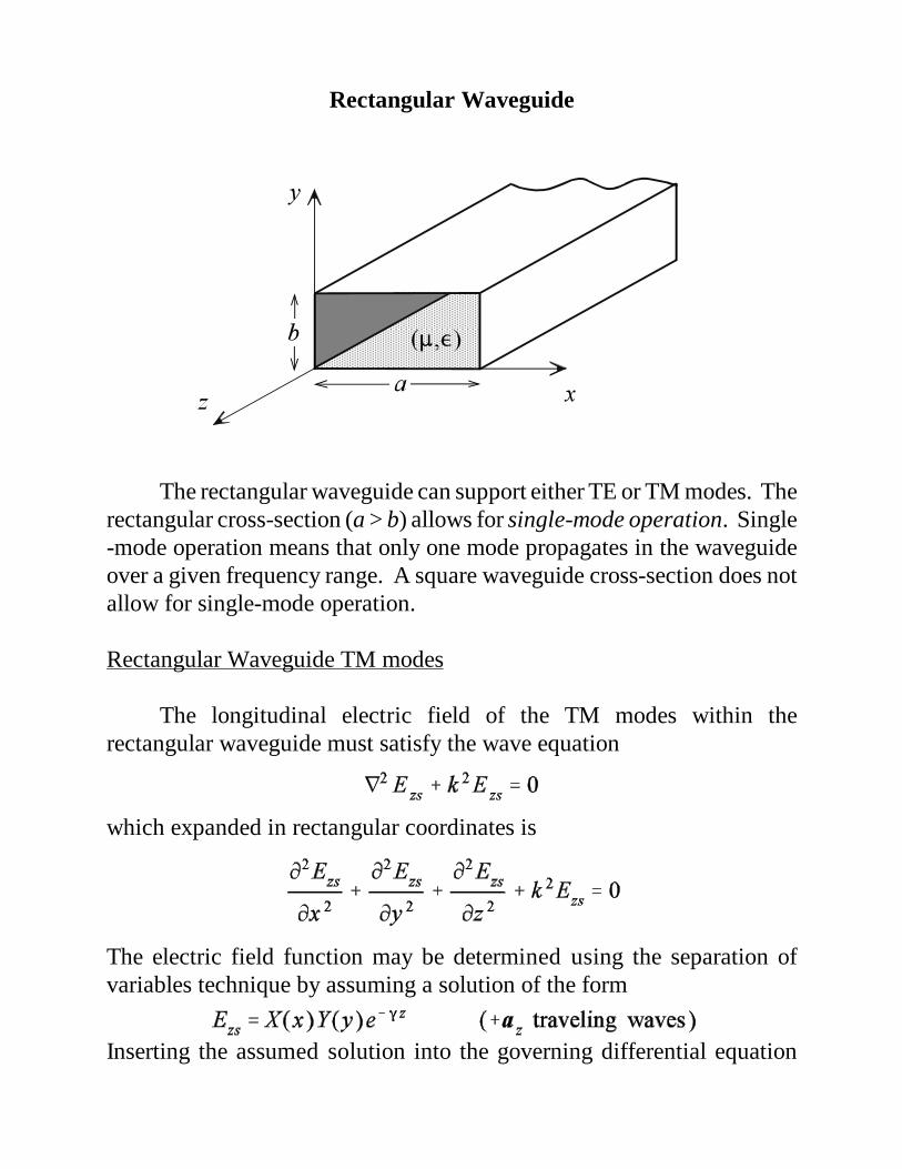
Rectangular Waveguide
The rectangular waveguide can support either TE or TM modes. Therectangular cross-section (a > b) allows for single-mode operation. Single-mode operation means that only one mode propagates in the waveguideover a given frequency range. A square waveguide cross-section does notallow for single-mode operation.
Rectangular Waveguide TM modes
The longitudinal electric field of the TM modes within therectangular waveguide must satisfy the wave equation
which expanded in rectangular coordinates is
The electric field function may be determined using the separation ofvariables technique by assuming a solution of the form
Inserting the assumed solution into the governing differential equation
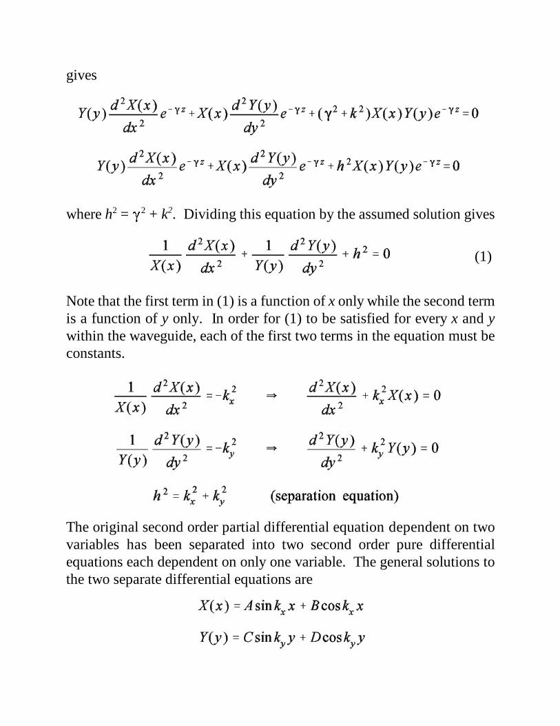
gives
where h2 = �2 + k2. Dividing this equation by the assumed solution gives
Note that the first term in (1) is a function of x only while the second termis a function of y only. In order for (1) to be satisfied for every x and ywithin the waveguide, each of the first two terms in the equation must beconstants.
The original second order partial differential equation dependent on twovariables has been separated into two second order pure differentialequations each dependent on only one variable. The general solutions tothe two separate differential equations are
(1)
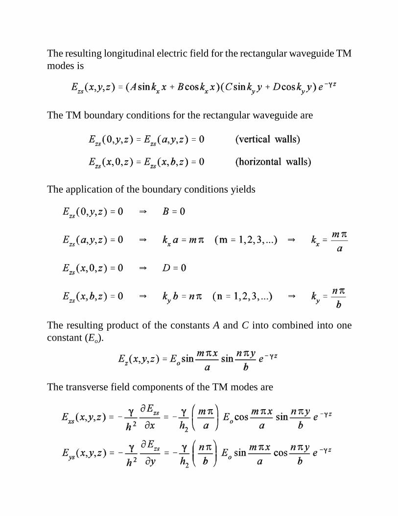
The resulting longitudinal electric field for the rectangular waveguide TMmodes is
The TM boundary conditions for the rectangular waveguide are
The application of the boundary conditions yields
The resulting product of the constants A and C into combined into oneconstant (Eo).
The transverse field components of the TM modes are
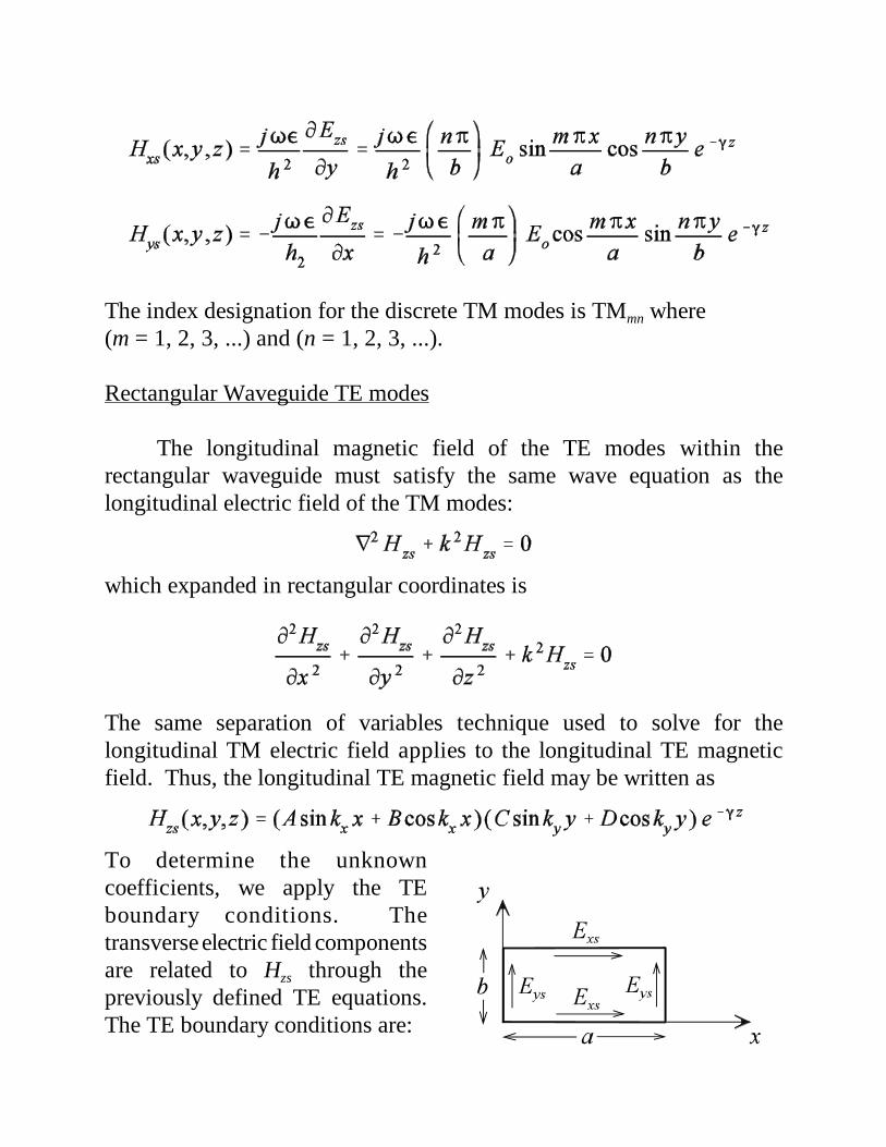
The index designation for the discrete TM modes is TMmn where (m = 1, 2, 3, ...) and (n = 1, 2, 3, ...).
Rectangular Waveguide TE modes
The longitudinal magnetic field of the TE modes within therectangular waveguide must satisfy the same wave equation as thelongitudinal electric field of the TM modes:
which expanded in rectangular coordinates is
The same separation of variables technique used to solve for thelongitudinal TM electric field applies to the longitudinal TE magneticfield. Thus, the longitudinal TE magnetic field may be written as
To determine the unknowncoefficients, we apply the TEboundary conditions. Thetransverse electric field componentsare related to Hzs through thepreviously defined TE equations.The TE boundary conditions are:
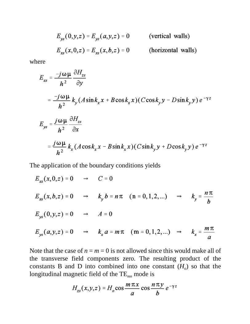
where
The application of the boundary conditions yields
Note that the case of n = m = 0 is not allowed since this would make all ofthe transverse field components zero. The resulting product of theconstants B and D into combined into one constant (Ho) so that thelongitudinal magnetic field of the TEmn mode is
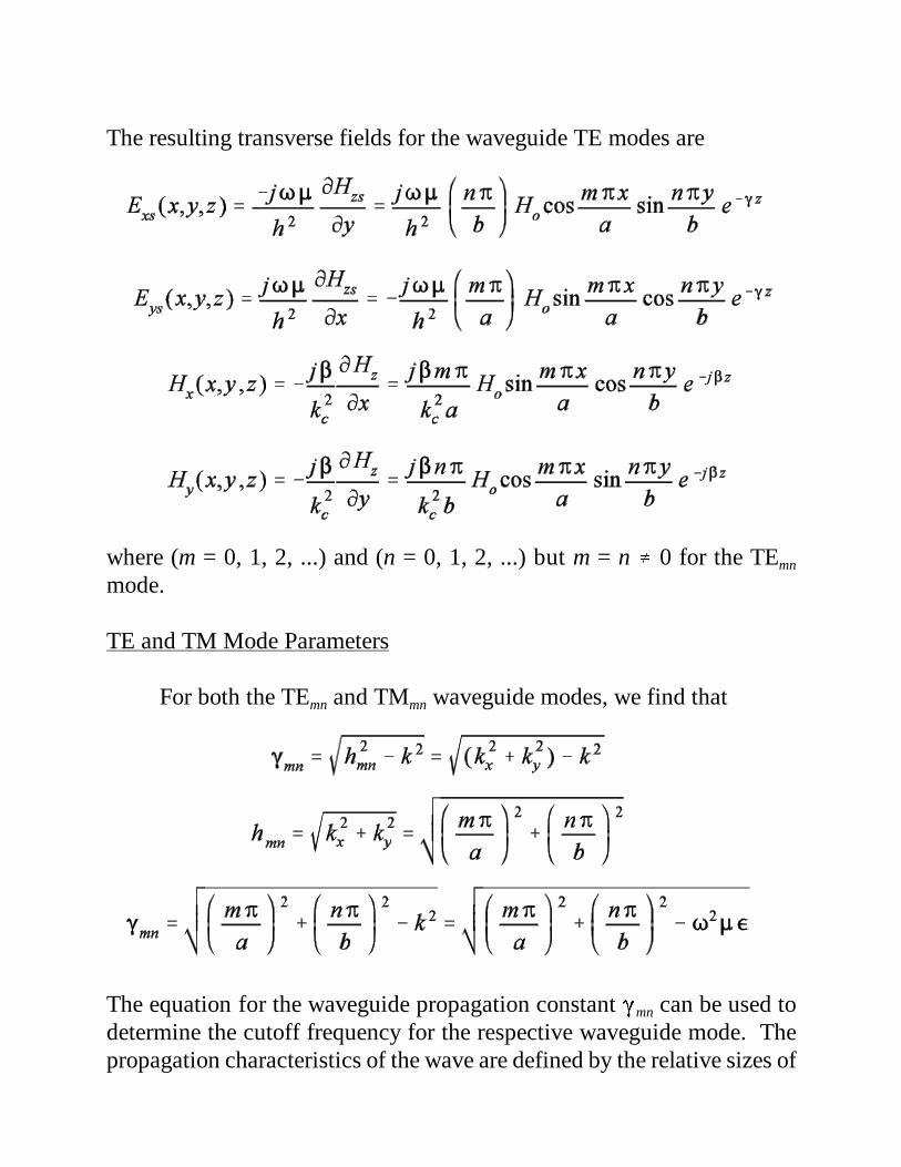
The resulting transverse fields for the waveguide TE modes are
where (m = 0, 1, 2, ...) and (n = 0, 1, 2, ...) but m = n � 0 for the TEmn
mode.
TE and TM Mode Parameters
For both the TEmn and TMmn waveguide modes, we find that
The equation for the waveguide propagation constant �mn can be used todetermine the cutoff frequency for the respective waveguide mode. Thepropagation characteristics of the wave are defined by the relative sizes of

the parameters hmn and k.
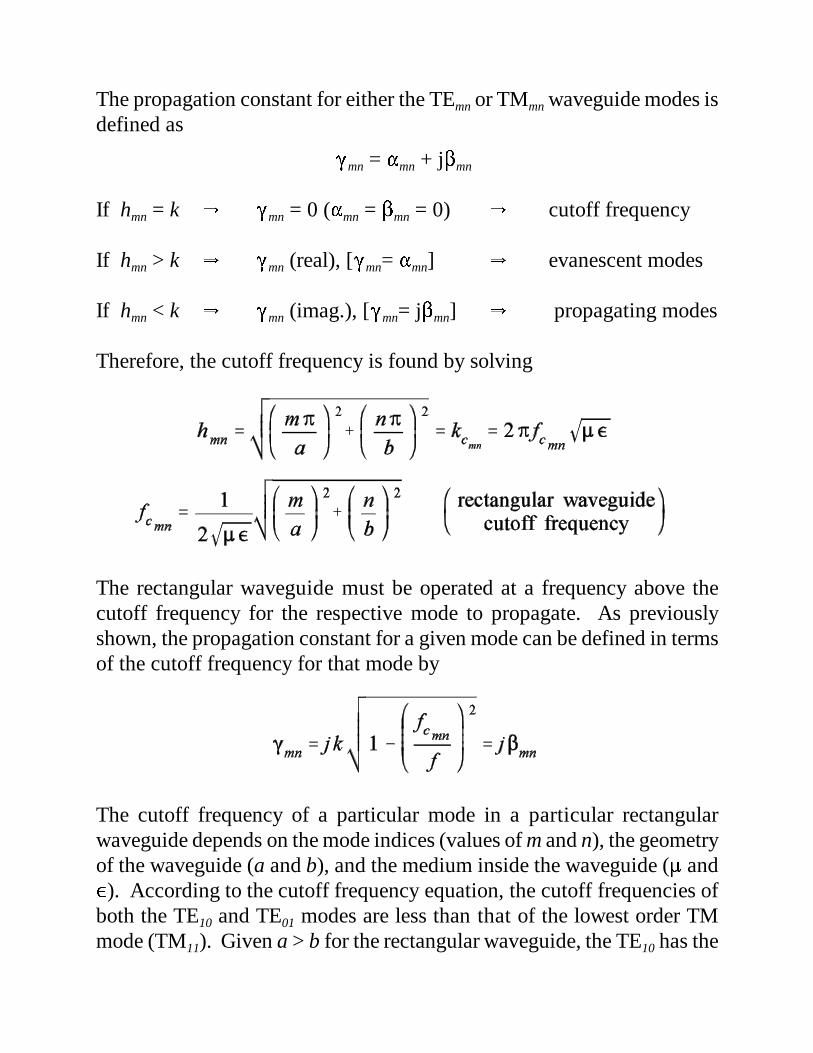
The propagation constant for either the TEmn or TMmn waveguide modes isdefined as
�mn = �mn + j�mn
If hmn = k � �mn = 0 (�mn = �mn = 0) � cutoff frequency
If hmn > k � �mn (real), [�mn= �mn] � evanescent modes
If hmn < k � �mn (imag.), [�mn= j�mn] � propagating modes
Therefore, the cutoff frequency is found by solving
The rectangular waveguide must be operated at a frequency above thecutoff frequency for the respective mode to propagate. As previouslyshown, the propagation constant for a given mode can be defined in termsof the cutoff frequency for that mode by
The cutoff frequency of a particular mode in a particular rectangularwaveguide depends on the mode indices (values of m and n), the geometryof the waveguide (a and b), and the medium inside the waveguide (� and�). According to the cutoff frequency equation, the cutoff frequencies ofboth the TE10 and TE01 modes are less than that of the lowest order TMmode (TM11). Given a > b for the rectangular waveguide, the TE10 has the
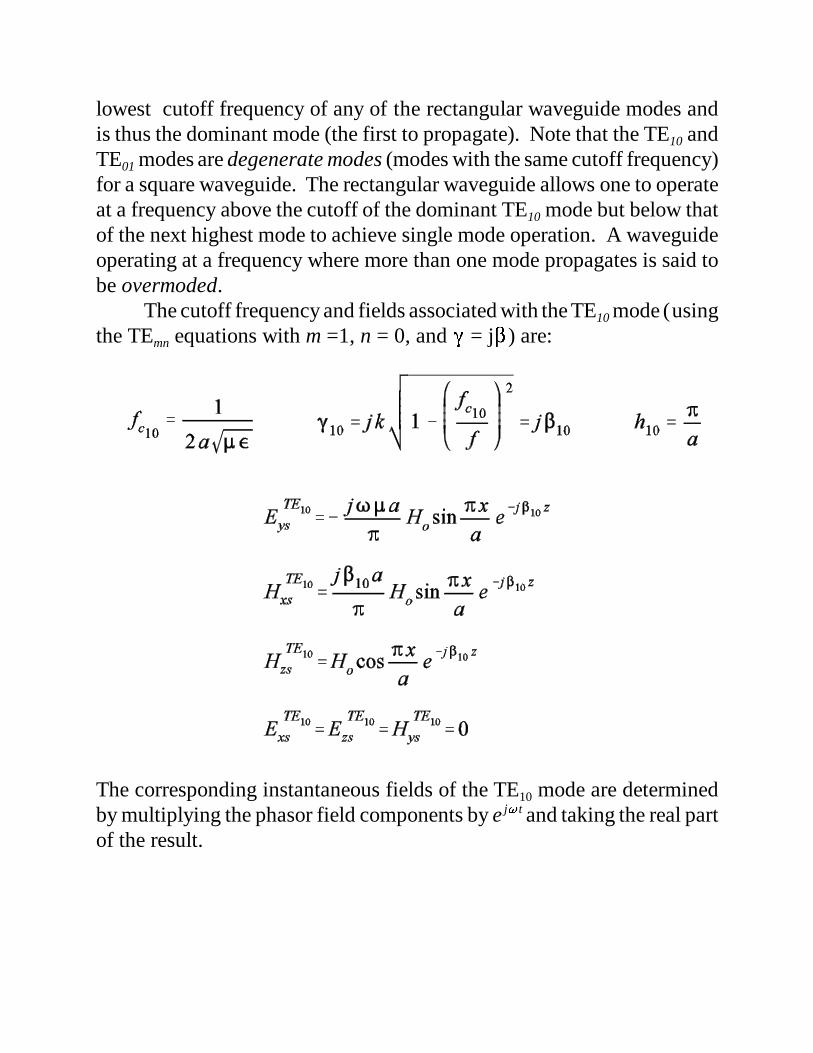
lowest cutoff frequency of any of the rectangular waveguide modes andis thus the dominant mode (the first to propagate). Note that the TE10 andTE01 modes are degenerate modes (modes with the same cutoff frequency)for a square waveguide. The rectangular waveguide allows one to operateat a frequency above the cutoff of the dominant TE10 mode but below thatof the next highest mode to achieve single mode operation. A waveguideoperating at a frequency where more than one mode propagates is said tobe overmoded.
The cutoff frequency and fields associated with the TE10 mode (usingthe TEmn equations with m =1, n = 0, and � = j�) are:
The corresponding instantaneous fields of the TE10 mode are determinedby multiplying the phasor field components by e j� t and taking the real partof the result.
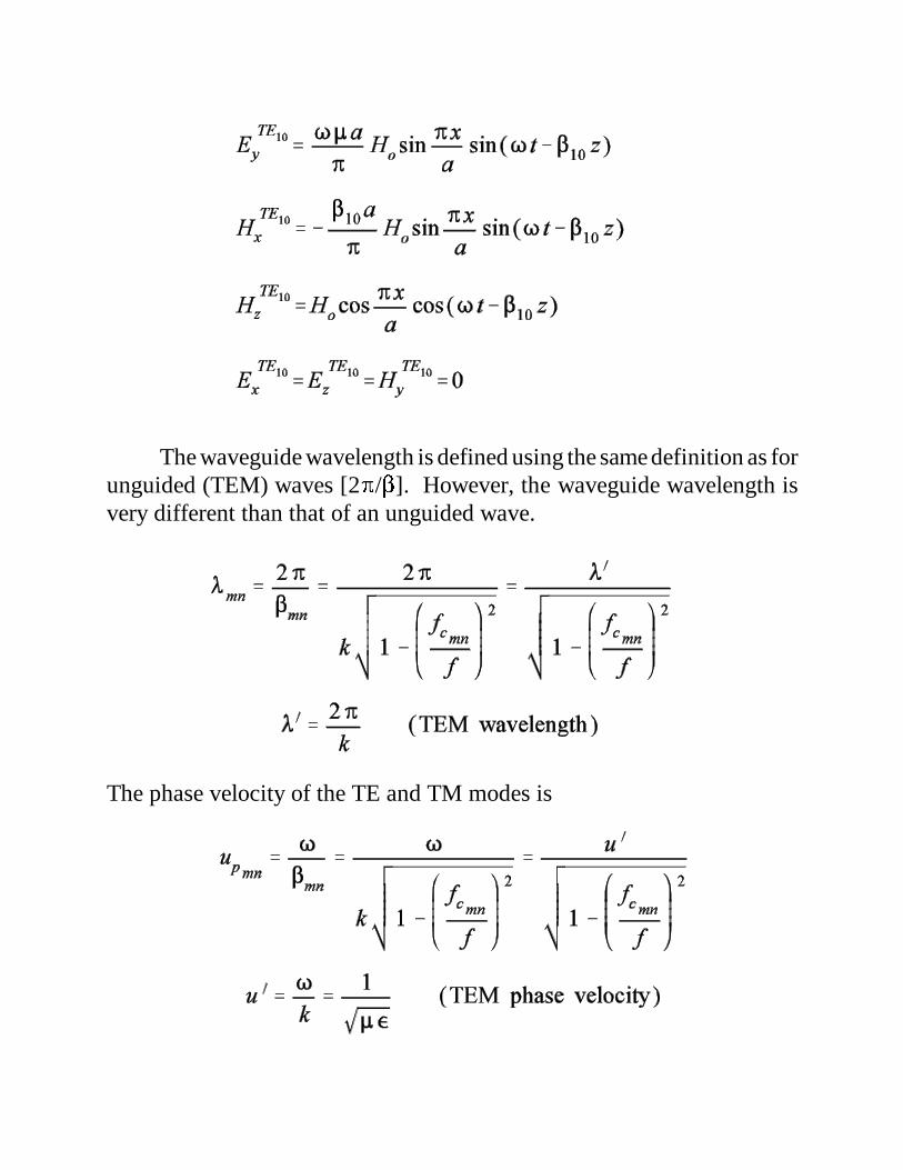
The waveguide wavelength is defined using the same definition as forunguided (TEM) waves [2�/�]. However, the waveguide wavelength isvery different than that of an unguided wave.
The phase velocity of the TE and TM modes is
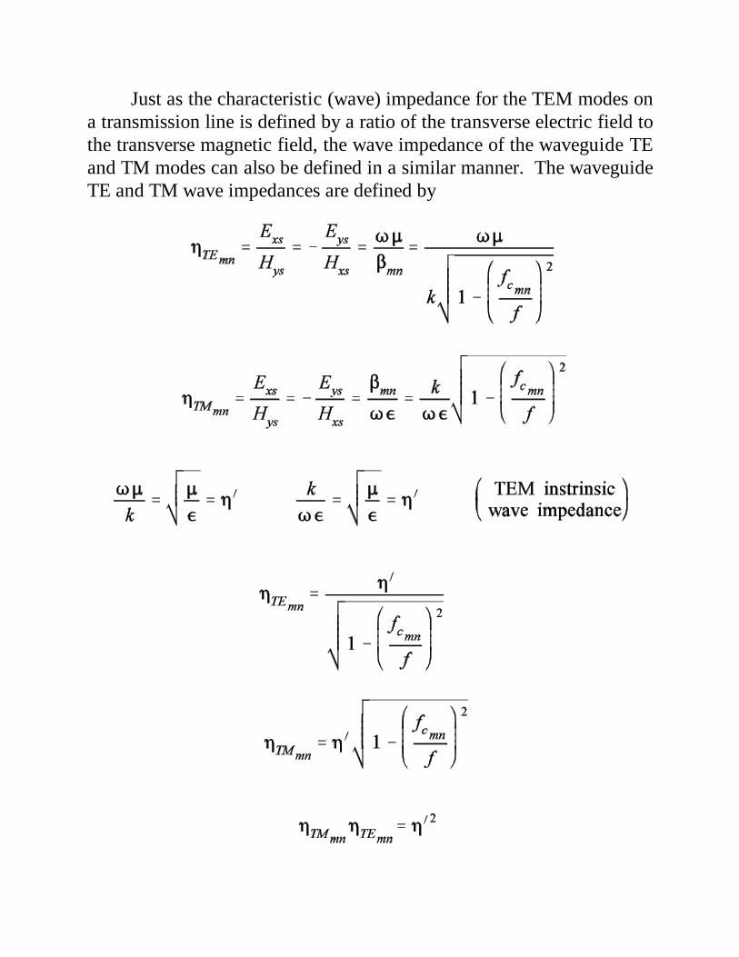
Just as the characteristic (wave) impedance for the TEM modes ona transmission line is defined by a ratio of the transverse electric field tothe transverse magnetic field, the wave impedance of the waveguide TEand TM modes can also be defined in a similar manner. The waveguideTE and TM wave impedances are defined by
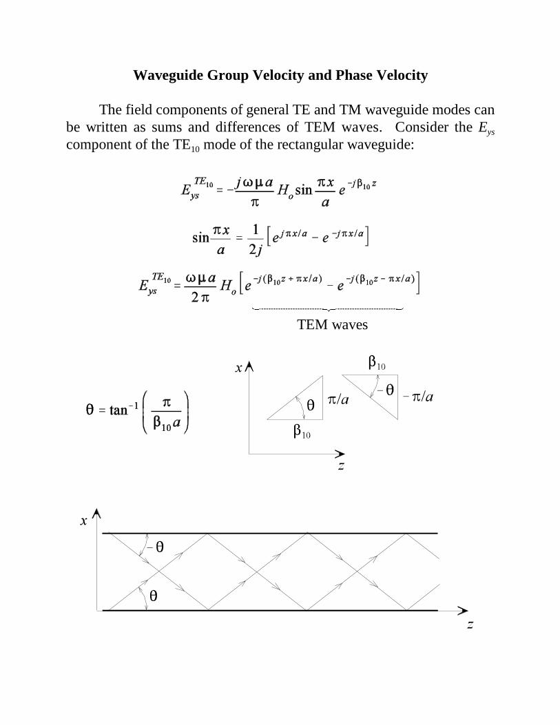
Waveguide Group Velocity and Phase Velocity
The field components of general TE and TM waveguide modes canbe written as sums and differences of TEM waves. Consider the Eys
component of the TE10 mode of the rectangular waveguide:
TEM waves������������������������������������������������������
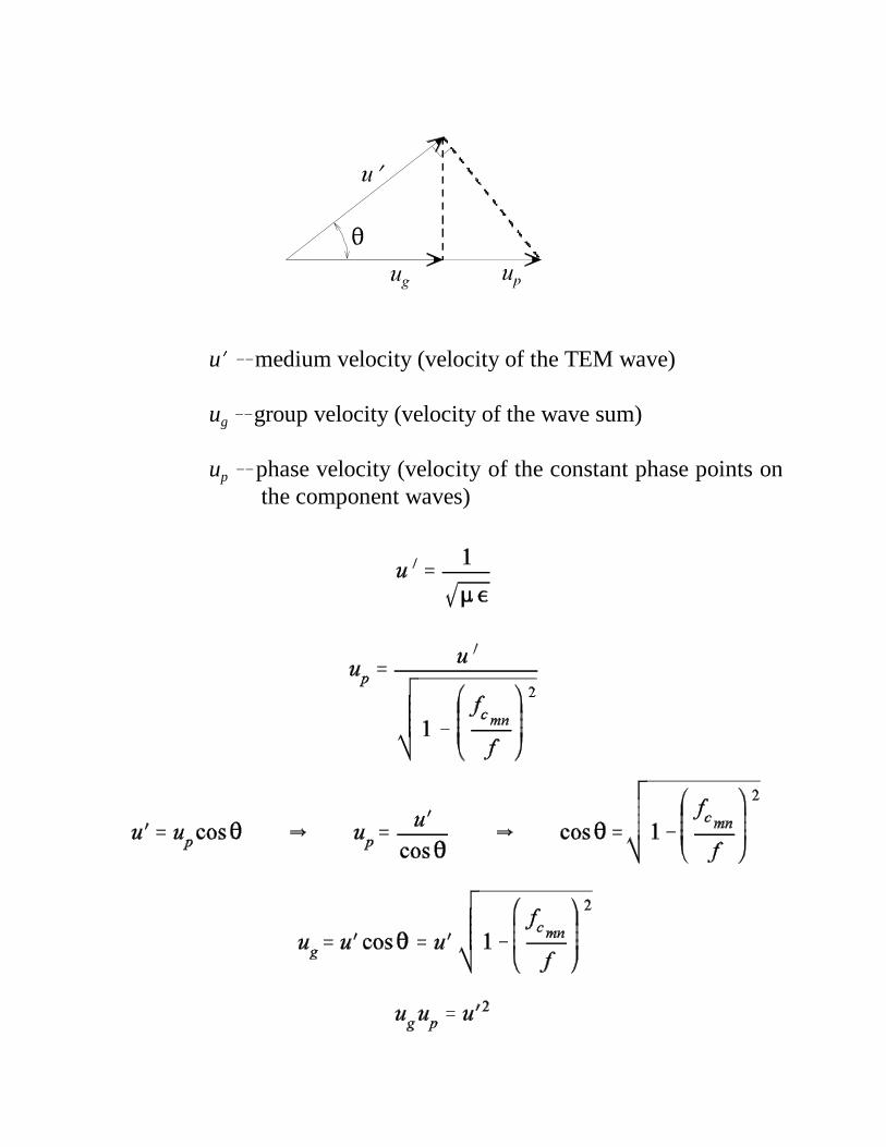
u� � medium velocity (velocity of the TEM wave)
ug � group velocity (velocity of the wave sum)
up � phase velocity (velocity of the constant phase points onthe component waves)
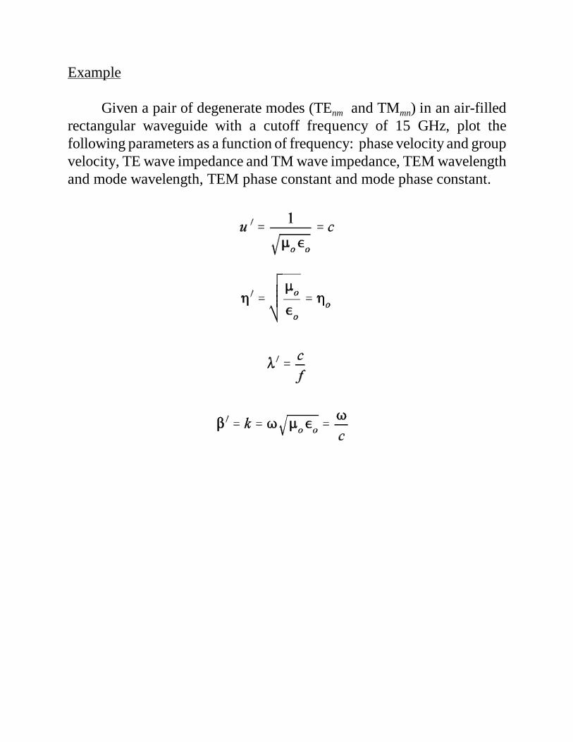
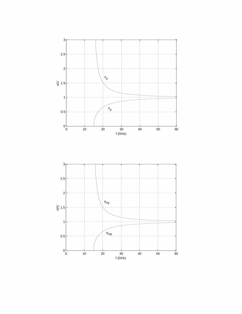
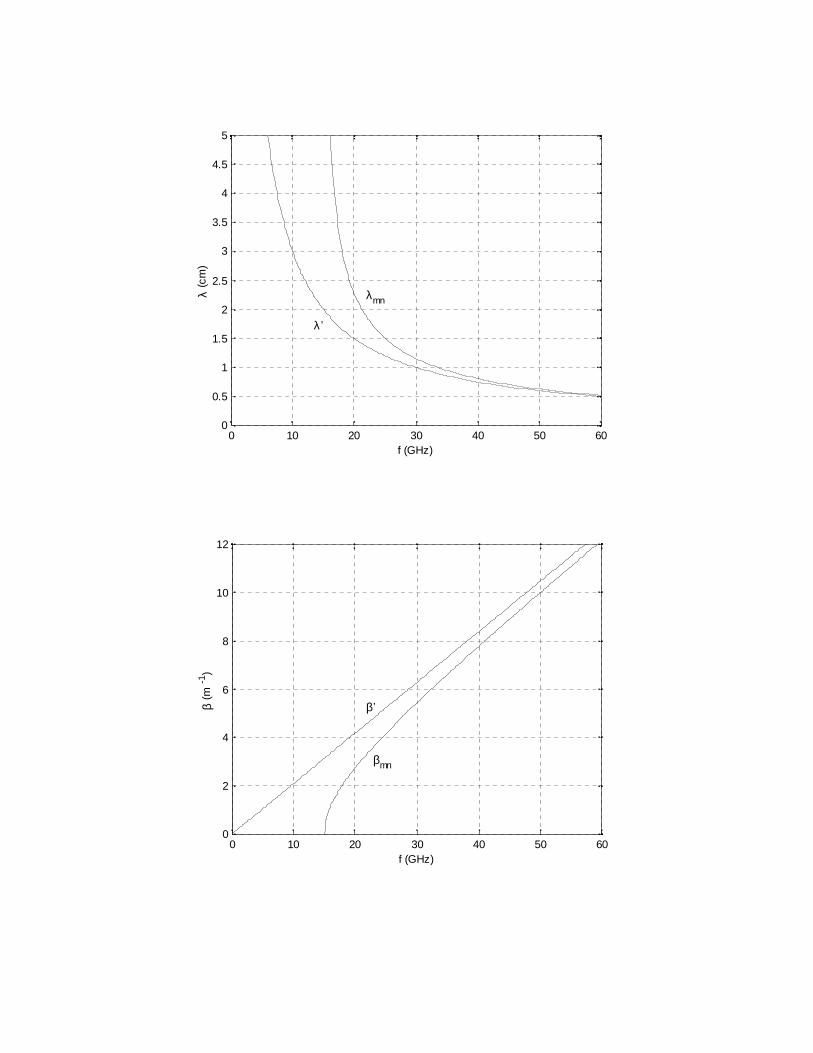
Example
Given a pair of degenerate modes (TEnm and TMmn) in an air-filledrectangular waveguide with a cutoff frequency of 15 GHz, plot thefollowing parameters as a function of frequency: phase velocity and groupvelocity, TE wave impedance and TM wave impedance, TEM wavelengthand mode wavelength, TEM phase constant and mode phase constant.
0 10 20 30 40 50 600
0.5
1
1.5
2
2.5
3
f (GHz)
u/u’
up
ug
0 10 20 30 40 50 600
0.5
1
1.5
2
2.5
3
f (GHz)
η/η’
ηTE
ηTM
0 10 20 30 40 50 600
0.5
1
1.5
2
2.5
3
3.5
4
4.5
5
f (GHz)
λ (c
m)
λ ’
λmn
0 10 20 30 40 50 600
2
4
6
8
10
12
f (GHz)
β (m
-1)
β’
βmn
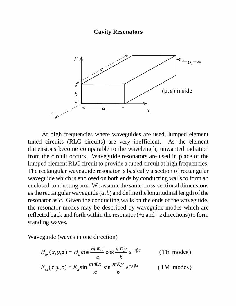
Cavity Resonators
At high frequencies where waveguides are used, lumped elementtuned circuits (RLC circuits) are very inefficient. As the elementdimensions become comparable to the wavelength, unwanted radiationfrom the circuit occurs. Waveguide resonators are used in place of thelumped element RLC circuit to provide a tuned circuit at high frequencies.The rectangular waveguide resonator is basically a section of rectangularwaveguide which is enclosed on both ends by conducting walls to form anenclosed conducting box. We assume the same cross-sectional dimensionsas the rectangular waveguide (a,b) and define the longitudinal length of theresonator as c. Given the conducting walls on the ends of the waveguide,the resonator modes may be described by waveguide modes which arereflected back and forth within the resonator (+z and �z directions) to formstanding waves.
Waveguide (waves in one direction)
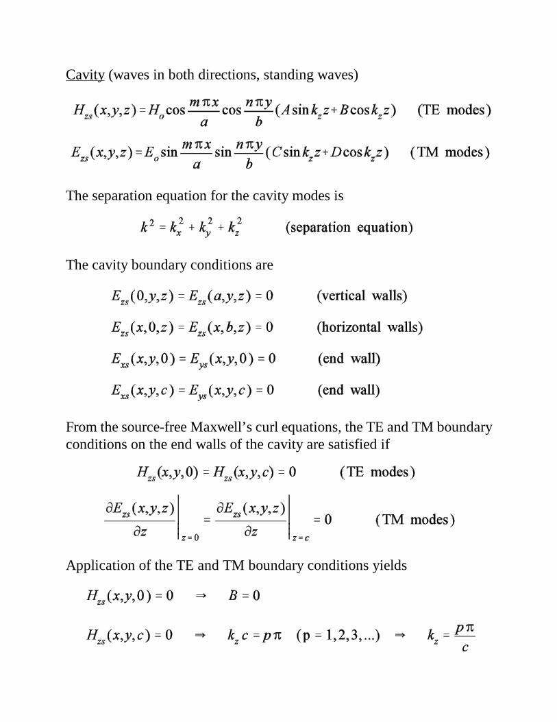
Cavity (waves in both directions, standing waves)
The separation equation for the cavity modes is
The cavity boundary conditions are
From the source-free Maxwell’s curl equations, the TE and TM boundaryconditions on the end walls of the cavity are satisfied if
Application of the TE and TM boundary conditions yields
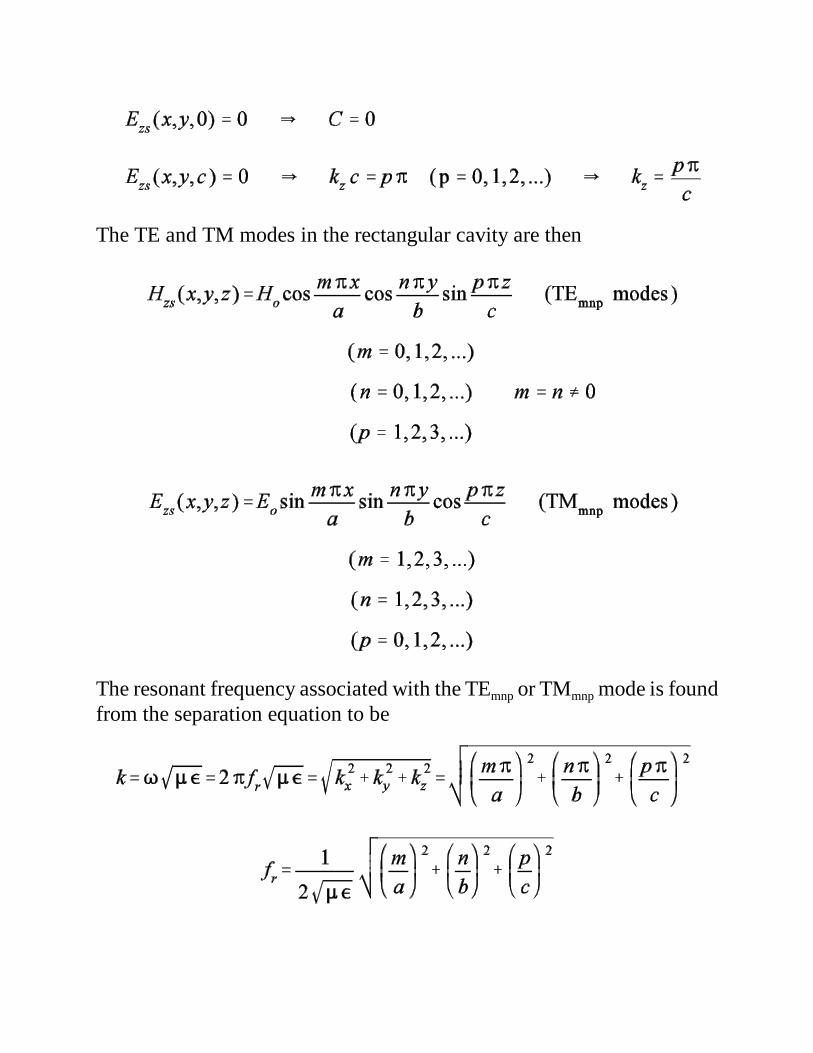
The TE and TM modes in the rectangular cavity are then
The resonant frequency associated with the TEmnp or TMmnp mode is foundfrom the separation equation to be
The lowest order modes in a rectangular cavity are the TM110, TE101,and TE011 modes. Which of these modes is the dominant mode depends onthe relative dimensions of the resonator. The quality factor (Q) of awaveguide resonator is defined the same way as that for an RLC network.
where the energy lost per cycle is that energy dissipated in the form of heatin the cavity walls (ohmic losses). The resonator quality factor is inverselyproportional to its bandwidth. Given a resonator made from a conductorsuch as copper or aluminum, the ohmic losses are very small and thequality factor is large (high Q, small bandwidth). Thus, resonators areused in applications such as oscillators, filters, and tuned amplifiers.Comparing the modes of the rectangular resonator with the propagatingmodes in the rectangular waveguide, we see that the waveguide modesexist over a wide band (the rectangular waveguide acts like a high-passfilter) while the rectangular resonator modes exist over a very narrow band(the rectangular resonator acts like a band-pass filter).
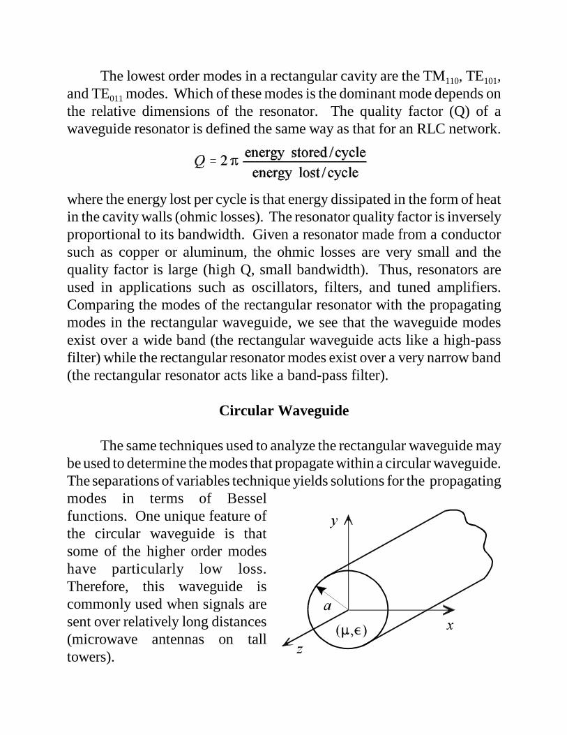
Circular Waveguide
The same techniques used to analyze the rectangular waveguide maybe used to determine the modes that propagate within a circular waveguide.The separations of variables technique yields solutions for the propagatingmodes in terms of Besselfunctions. One unique feature ofthe circular waveguide is thatsome of the higher order modeshave particularly low loss.Therefore, this waveguide iscommonly used when signals aresent over relatively long distances(microwave antennas on talltowers).
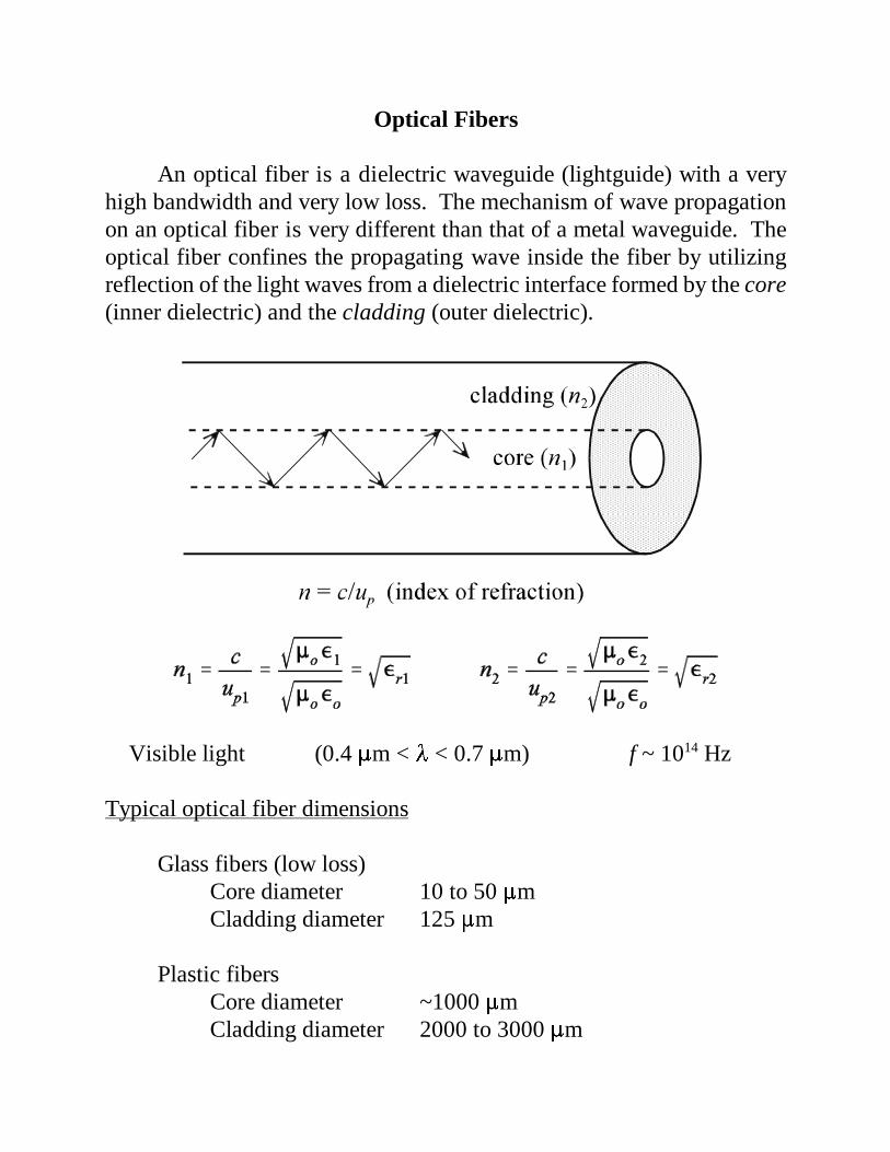
Optical Fibers
An optical fiber is a dielectric waveguide (lightguide) with a veryhigh bandwidth and very low loss. The mechanism of wave propagationon an optical fiber is very different than that of a metal waveguide. Theoptical fiber confines the propagating wave inside the fiber by utilizingreflection of the light waves from a dielectric interface formed by the core(inner dielectric) and the cladding (outer dielectric).
Visible light (0.4 �m < � < 0.7 �m) f ~ 1014 Hz
Typical optical fiber dimensions
Glass fibers (low loss)Core diameter 10 to 50 �mCladding diameter 125 �m
Plastic fibersCore diameter ~1000 �mCladding diameter 2000 to 3000 �m
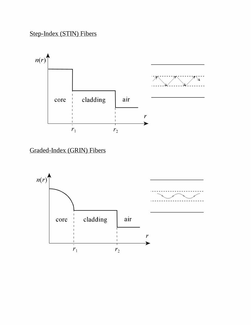
Step-Index (STIN) Fibers
Graded-Index (GRIN) Fibers