Embed Size (px)
Citation preview
- 1 - Copyright © 2004
WaveLink PDH
Digital Microwave Communication Equipment
User Guide and Product Specifications
Beijing US-Sino Diverse Telecom Equipment Co., Ltd.
- 2 - Copyright © 2004
Preface
Thank you for choosing the digital microwave communication product from US -Sino
Diverse Telecom Equipment Co. This book: for WaveLink PDH Digital Microwave
Communication Equipment: User Guide and Product Specifications contains in-depth and
detailed information on how to install, use, and test the communication system equipment. It is
designed for system managers, telecommunications engineers, and electrical engineers, who
involve in installation, operation, troubleshooting, and monitoring of WaveLink PDH systems.
Please review this User Guide carefully and keep it for references. It will help you get the most
out of the product,
We value your working with our company very much. US -Sino Diverse Co. is an ISO 9001
System Registration certified company. We encourage you to call us anytime with your
comments and suggestions on our pro duct. We look forward to serving you well.
For more information about WaveLink products, please contact us at:
- 3 - Copyright © 2004
Section 1 WaveLink PDH Product Description
1.1 Overview
As one of popular ways of wireless communications, microwave communication has some
well-known advantages such as flexibility, easy recovery from disaster, and mobility. WaveLink
PDH Microwave Communication Equipment product, which provides full -duplex channels
between two line-of-sight (LOS) sites, is developed solely by Beijing US-Sino Diverse Telecom
Co. Diverse follows ISO9001 strictly to control the quality of its product.
According to the equipment structure, t he WaveLink PDH product family has two types of
product: standard IDU+ODU type and Outdoor-integrated type. Covering the f requency range
from 7 to 23GHz, necessary to satisfy the largest range of propagation conditions as well as
network configurations that gives also the ability to have the highest spectrum efficiency in those
band ranges with QPSK modulation. The family cov ers the capacities of 2×2, 4×2, 8×2, 16×
2Mbit/s,34Mbit/s with QPSK and can achieve typical distances from 10 to 50km for the 7/8 GHz
band, from 5 to 30km for the microwave frequencies (13 to 18GHz), from a few hundred meters
up to 10km for millimeter wave frequencies (23GHz).
To design, many technologies have been taken to guarantee the high quality of products.
CAD and CAM are adopted to design the equipments, because of high -reliability and
high-stability. Using MMIC and FPGA for improving integration level; using modularization and
frequency synthesization technologies for improving stability of Tx/Rx frequency and LO (local
oscillate) frequency; using QPSK modulator/de -modulator for improving BER of system through
employing data stream processing technologies; moreover, nearly perfect supervision interfaces
design can help maintenance man to manage and test the systems easier and more flexible.
- 4 - Copyright © 2004
1.2 Product description
1.2.1 General Description
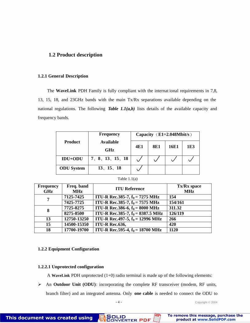
The WaveLink PDH Family is fully compliant with the internat ional requirements in 7,8,
13, 15, 18, and 23GHz bands with the main Tx/Rx separations available depending on the
national regulations. The following Table 1.1(a,b) lists details of the available capacity and
frequency bands.
Capacity(E1=2.048Mbit/s)
Product
Frequency
Available
GHz4E1 8E1 16E1 1E3
IDU+ODU 7、8、13、15、18
ODU System 13、15、18
Table 1.1(a)
FrequencyGHz
Freq. bandMHz
ITU Reference Tx/Rx spaceMHz
7125-7425 ITU-R Rec.385-7, f0 = 7275 MHz 15477425-7725 ITU-R Rec.385-7, f0 = 7575 MHz 154/1617725-8275 ITU-R Rec.386-6, f0 = 8000 MHz 311.3288275-8500 ITU-R Rec.385-7, f0 = 8387.5 MHz 126/119
13 12750-13250 ITU-R Rec.497-5, f0 = 12996 MHz 26615 14500-15350 ITU-R Rec.636, 42018 17700-19700 ITU-R Rec.595-4, f0 = 18700 MHz 1120
1.2.2 Equipment Configuration
1.2.2.1 Unprotected configuration
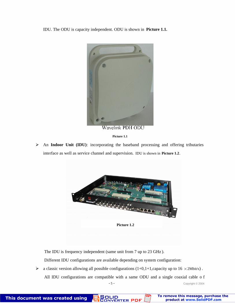
A WaveLink PDH unprotected (1+0) radio terminal is made up of the following elements:
An Outdoor Unit (ODU): incorporating the complete RF transceiver (modem, RF units,
branch filter) and an integrated antenna. Only one cable is needed to connect the ODU to
- 5 - Copyright © 2004
IDU. The ODU is capacity independent. ODU is shown in Picture 1.1.
Wavelink PDH ODU
Picture 1.1
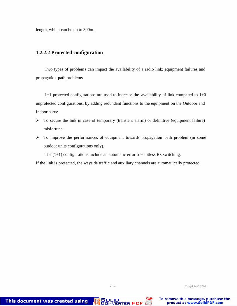
An Indoor Unit (IDU): incorporating the baseband processing and offering tributaries
interface as well as service channel and supervision. IDU is shown in Picture 1.2.
The IDU is frequency independent (same unit from 7 up to 23 GHz ).
Different IDU configurations are available depending on system configuration:
a classic version allowing all possible configurations (1+0,1+1,capacity up to 16 ×2Mbit/s) .
All IDU configurations are compatible with a same ODU and a single coaxial cable o f
Picture 1.2
- 6 - Copyright © 2004
length, which can be up to 300m.
1.2.2.2 Protected configuration
Two types of problems can impact the availability of a radio link: equipment failures and
propagation path problems.
1+1 protected configurations are used to increase the availability of link compared to 1+0
unprotected configurations, by adding redundant functions to the equipment on the Outdoor and
Indoor parts:
To secure the link in case of temporary (transient alarm) or definitive (equipment failure)
misfortune.
To improve the performances of equipment towards propagation path problem (in some
outdoor units configurations only).
The (1+1) configurations include an automatic error free hitless Rx switching.
If the link is protected, the wayside traffic and auxiliary channels are automat ically protected.
- 7 - Copyright © 2004
Section 2 Product Specifications and Characteristics
2.1 Product pictures
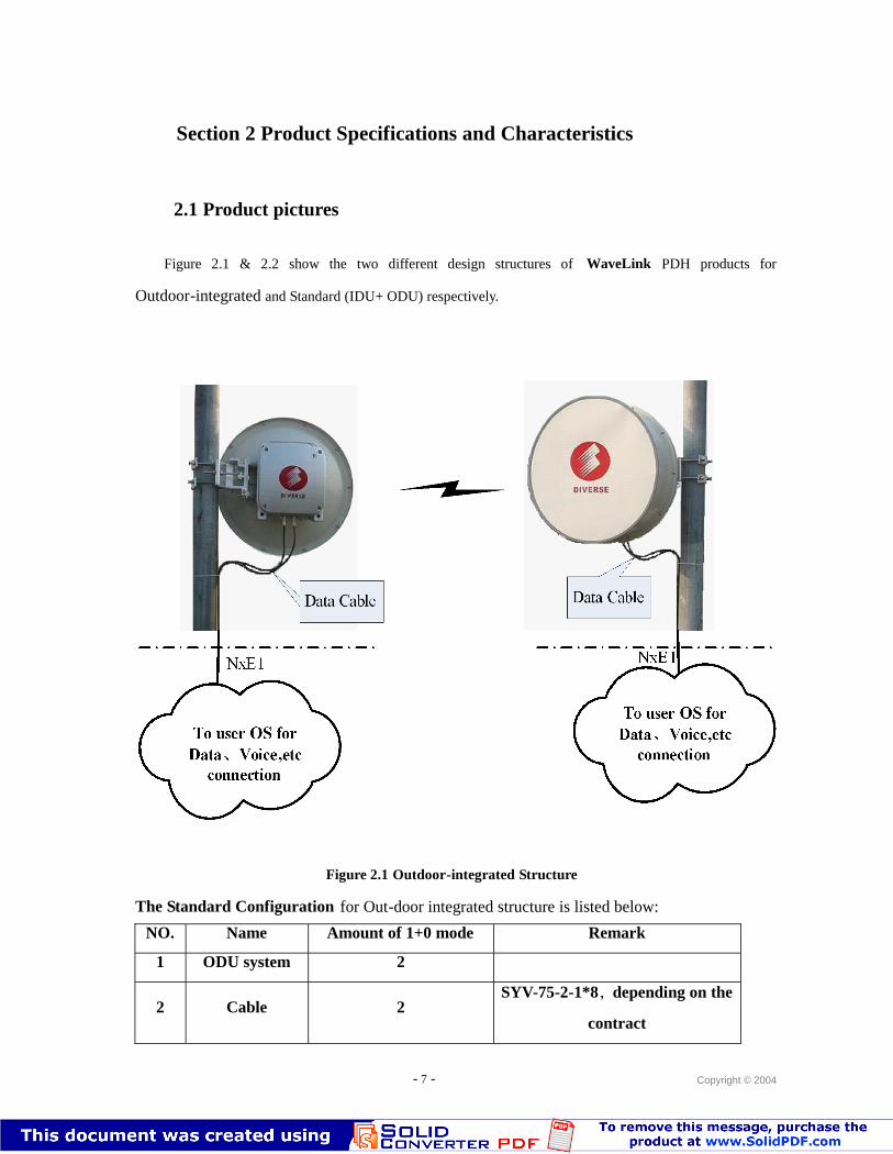
Figure 2.1 & 2.2 show the two different design structures of WaveLink PDH products for
Outdoor-integrated and Standard (IDU+ ODU) respectively.
To user OS forData、Voice,etc
connection
NxE1 NxE1
Data Cable Data Cable
To user OS forData、Voice,etc
connection
Figure 2.1 Outdoor-integrated Structure
The Standard Configuration for Out-door integrated structure is listed below:
NO. Name Amount of 1+0 mode Remark
1 ODU system 2
2 Cable 2SYV-75-2-1*8,depending on the
contract
- 8 - Copyright © 2004
3 Antenna 2
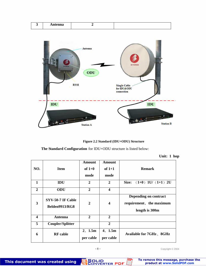
Figure 2.2 Standard (IDU+ODU) Structure
The Standard Configuration for IDU+ODU structure is listed below:
Unit: 1 hop
NO. Item
Amount
of 1+0
mode
Amount
of 1+1
mode
Remark
1 IDU 2 2 Size: (1+0)1U/(1+1)2U
2 ODU 2 4
3SYV-50-7 IF Cable
Belden9913/RG82 4
Depending on contract
requirement,the maximum
length is 300m
4 Antenna 2 2
5 Coupler/Splitter 2
6 RF cable2,1.5m
per cable
4,1.5m
per cableAvailable for 7GHz、8GHz
- 9 - Copyright © 2004
2.2 Technical Specifications
2.2.1 E1
Velocity Capacity: 4×2048Kb/s, 8×2048Kb/s, 16×2048Kb/s;
Allowable frequency windage: ±50ppm; Frequency Stability
Line Code: HDB3
Length of cable: 0~150 meters;
Interfaces: BNC 75Ωunbalance.
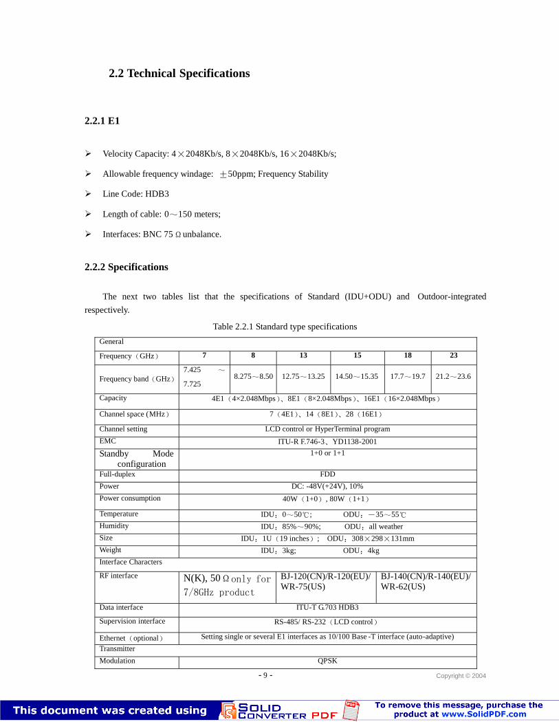
2.2.2 Specifications
The next two tables list that the specifications of Standard (IDU+ODU) and Outdoor-integrated
respectively.
Table 2.2.1 Standard type specifications
General
Frequency(GHz) 7 8 13 15 18 23
Frequency band(GHz)7.425 ~
7.7258.275~8.50 12.75~13.25 14.50~15.35 17.7~19.7 21.2~23.6
Capacity 4E1(4×2.048Mbps)、8E1(8×2.048Mbps)、16E1(16×2.048Mbps)
Channel space (MHz) 7(4E1)、14(8E1)、28(16E1)
Channel setting LCD control or HyperTerminal program
EMC ITU-R F.746-3、YD1138-2001
Standby Modeconfiguration
1+0 or 1+1
Full-duplex FDD
Power DC: -48V(+24V), 10%
Power consumption 40W(1+0), 80W(1+1)
Temperature IDU:0~50℃; ODU:-35~55℃Humidity IDU:85%~90%; ODU:all weather
Size IDU:1U(19 inches); ODU:308×298×131mm
Weight IDU:3kg; ODU:4kg
Interface Characters
RF interface N(K), 50Ωonly for
7/8GHz product
BJ-120(CN)/R-120(EU)/WR-75(US)
BJ-140(CN)/R-140(EU)/WR-62(US)
Data interface ITU-T G.703 HDB3
Supervision interface RS-485/ RS-232(LCD control)
Ethernet(optional) Setting single or several E1 interfaces as 10/100 Base -T interface (auto-adaptive)
Transmitter
Modulation QPSK
- 10 - Copyright © 2004
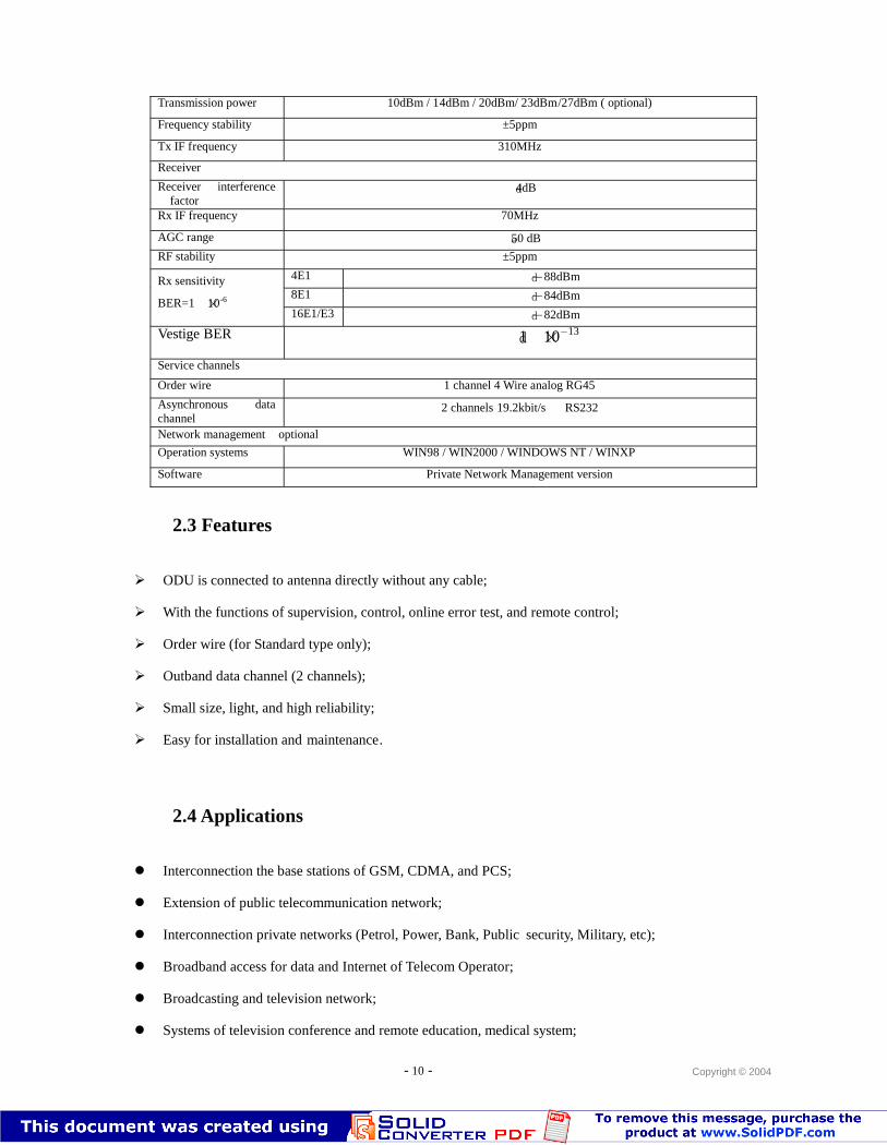
Transmission power 10dBm / 14dBm / 20dBm/ 23dBm/27dBm ( optional)
Frequency stability ±5ppm
Tx IF frequency 310MHz
Receiver
Receiver interferencefactor
≤4dB
Rx IF frequency 70MHz
AGC range ≥50 dB
RF stability ±5ppm
4E1 ≤-88dBm
8E1 ≤-84dBmRx sensitivity
BER=1×10⁻⁶
16E1/E3 ≤-82dBm
Vestige BER ≤1×10-13
Service channels
Order wire 1 channel 4 Wire analog RG45
Asynchronous datachannel
2 channels 19.2kbit/s, RS232
Network management(optional)Operation systems WIN98 / WIN2000 / WINDOWS NT / WINXP
Software Private Network Management version
2.3 Features
ODU is connected to antenna directly without any cable;
With the functions of supervision, control, online error test, and remote control;
Order wire (for Standard type only);
Outband data channel (2 channels);
Small size, light, and high reliability;
Easy for installation and maintenance.
2.4 Applications
Interconnection the base stations of GSM, CDMA, and PCS;
Extension of public telecommunication network;
Interconnection private networks (Petrol, Power, Bank, Public security, Military, etc);
Broadband access for data and Internet of Telecom Operator;
Broadcasting and television network;
Systems of television conference and remote education, medical system;
- 11 - Copyright © 2004
Emergency communication system.
2.5 Optional configurations
To meet the potential requirements of clients, there are two options, which are Ethernet interface
configuration and Network management, can be provided that are mentioned in above tables.
Option 1: Ethernet interface description
Satisfy the protocols of IEEE802.3, 802.3u, 802.3x;
RJ45 Interface;
Half/Full Duplex auto-shift;
Configuration way 1: A single or several E1 interfaces can be set as 10/100 Base -T interface with the
condition of both terminals have Ethernet interface. In the case of it, each side must have the same
quantity of E1 interfaces to the opposite site.
Configuration way 2: Only a E1interface can be deployed as 10/100 Base -T interface with the condition
of one terminal has Ethernet interface and only E1 interface deployment for the other terminal. Main
business channel on both sides must be consistence.
Option 2: Network Management Software (Details is available in the following section 3)
Beside mentioned configurations, there are another three Auxiliary Channels can also be provided.
Data Interface:
Velocity: 19.2kb/s
Interface Type: RS232 or RS485
Supervision Interface:
Velocity: 19.2kb/s
Interface Type: RS232 or RS485
Order Wire (Only available to Standard type):
Interface: RJ11
16kbps ADPCM
All calling/Selective calling
- 12 - Copyright © 2004
Section 3 Ports and Interfaces
3.1 Outdoor-integrated type
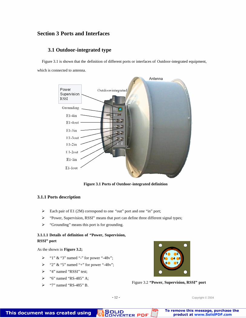
Figure 3.1 is shown that the definition of different ports or interfaces of Outdoor-integrated equipment,
which is connected to antenna.
Grounding
PowerSupervisionRSSI
Antenna
Outdoor-integrated
E1-1out
E1-1in
E1-2out
E1-2in
E1-3out
E1-3in
E1-4out
E1-4in
Figure 3.1 Ports of Outdoor-integrated definition
3.1.1 Ports description
Each pair of E1 (2M) correspond to one “out” port and one “in” port;
“Power, Supervision, RSSI” means that port can define three different signal types;
“Grounding” means this port is for grounding.
3.1.1.1 Details of definition of “Power, Supervision,
RSSI” port
As the shown in Figure 3.2;
“1” & “3” named “-” for power “-48v”;
“2” & “5” named “+” for power “-48v”;
“4” named “RSSI” test;
“6” named “RS-485” A;
“7” named “RS-485” B.Figure 3.2 “Power, Supervision, RSSI” port
- 13 - Copyright © 2004
3.2 Standard type (IDU+ODU)
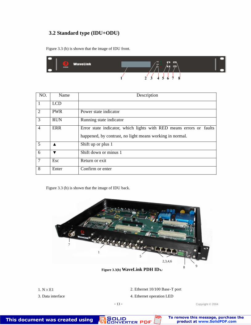
Figure 3.3 (b) is shown that the image of IDU front.
NO. Name Description
1 LCD
2 PWR Power state indicator
3 RUN Running state indicator
4 ERR Error state indicator, which lights with RED means errors or faults
happened, by contrast, no light means working in normal.
5 ▲ Shift up or plus 1
6 ▼ Shift down or minus 1
7 Esc Return or exit
8 Enter Confirm or enter
Figure 3.3 (b) is shown that the image of IDU back.
Figure 3.3(b) WaveLink PDH IDU
1. N×E1 2. Ethernet 10/100 Base-T port
3. Data interface 4. Ethernet operation LED
8
51
92,3,4,6
7
- 14 - Copyright © 2004
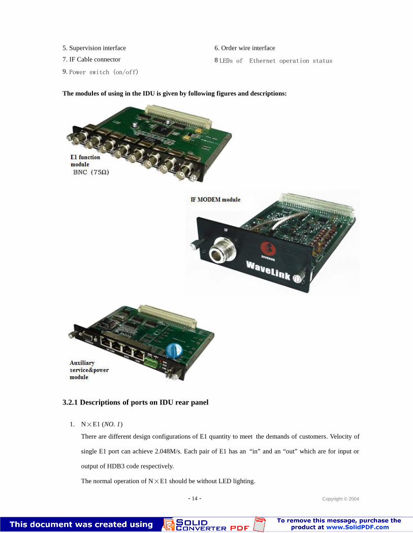
5. Supervision interface 6. Order wire interface
7. IF Cable connector 8 LEDs of Ethernet operation status
9. Power switch (on/off)
The modules of using in the IDU is given by following figures and descriptions:
3.2.1 Descriptions of ports on IDU rear panel
1. N×E1 (NO. 1)
There are different design configurations of E1 quantity to meet the demands of customers. Velocity of
single E1 port can achieve 2.048M/s. Each pair of E1 has an “in” and an “out” which are for input or
output of HDB3 code respectively.
The normal operation of N×E1 should be without LED lighting.
- 15 - Copyright © 2004
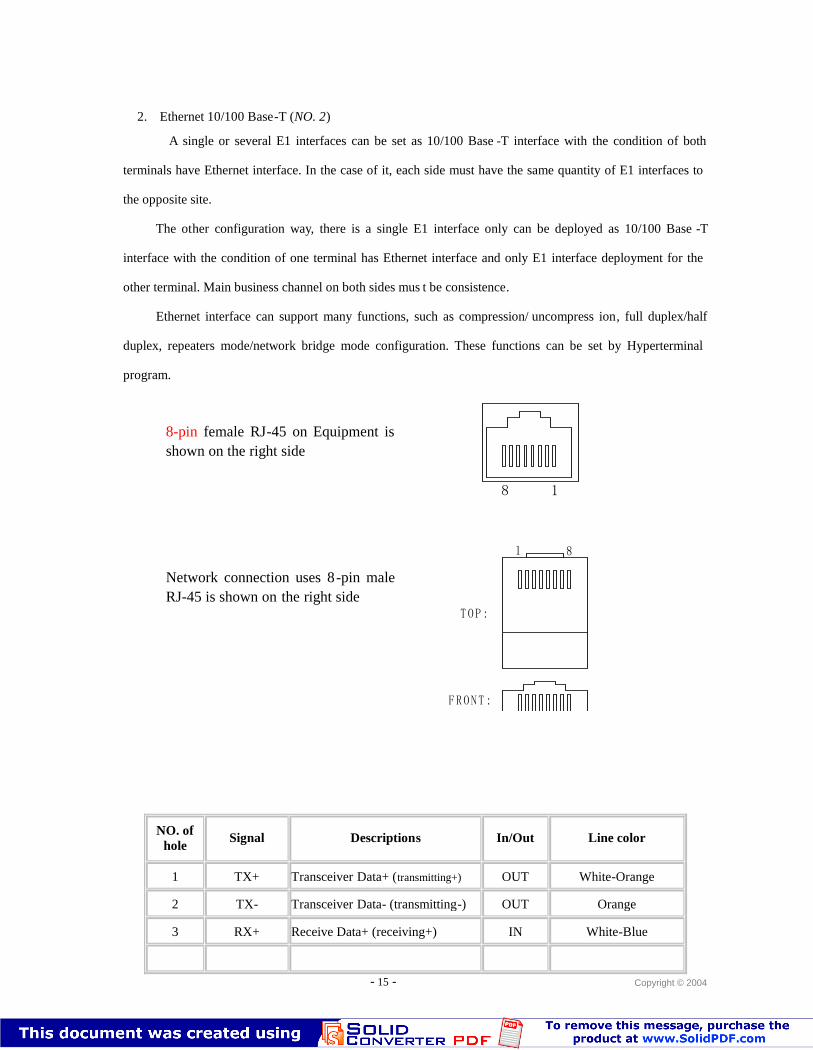
2. Ethernet 10/100 Base-T (NO. 2)
A single or several E1 interfaces can be set as 10/100 Base -T interface with the condition of both
terminals have Ethernet interface. In the case of it, each side must have the same quantity of E1 interfaces to
the opposite site.
The other configuration way, there is a single E1 interface only can be deployed as 10/100 Base -T
interface with the condition of one terminal has Ethernet interface and only E1 interface deployment for the
other terminal. Main business channel on both sides mus t be consistence.
Ethernet interface can support many functions, such as compression/ uncompress ion, full duplex/half
duplex, repeaters mode/network bridge mode configuration. These functions can be set by Hyperterminal
program.
NO. ofhole
Signal Descriptions In/Out Line color
1 TX+ Transceiver Data+ (transmitting+) OUT White-Orange
2 TX- Transceiver Data- (transmitting-) OUT Orange
3 RX+ Receive Data+ (receiving+) IN White-Blue
4 n/c Not connected (vacancy) Green
8-pin female RJ-45 on Equipment isshown on the right side
Network connection uses 8-pin maleRJ-45 is shown on the right side
18
1 8
1 8
T O P :
F R O N T :
- 16 - Copyright © 2004
5 n/c Not connected (vacancy) White-Green
6 RX- Receive Data- (receiving-) IN Blue
7 n/c Not connected (vacancy) White-Brown
8 n/c Not connected (vacancy) Brown
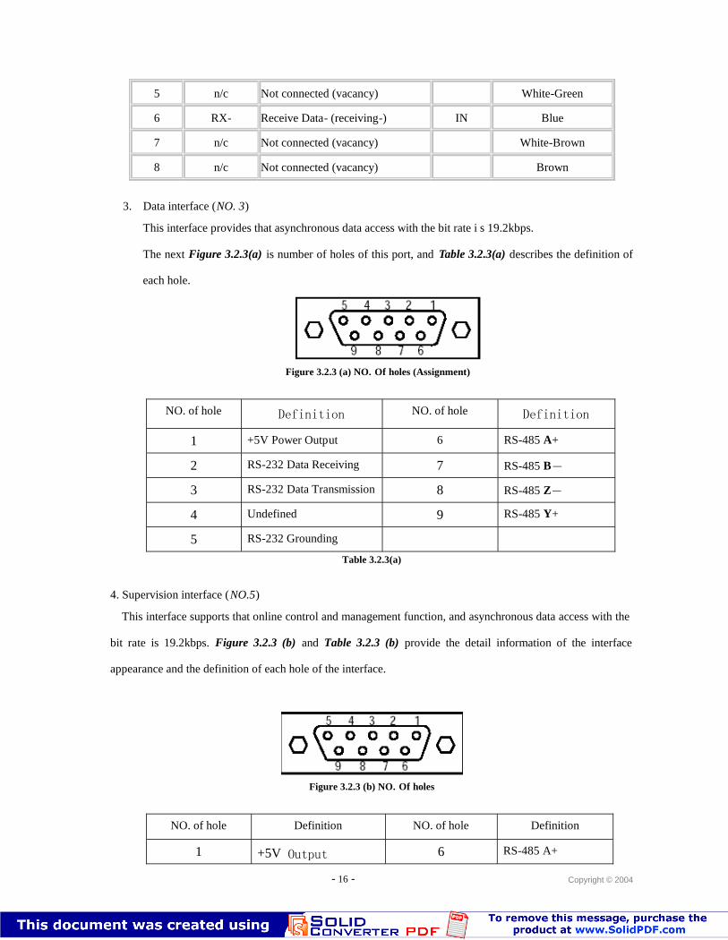
3. Data interface (NO. 3)
This interface provides that asynchronous data access with the bit rate i s 19.2kbps.
The next Figure 3.2.3(a) is number of holes of this port, and Table 3.2.3(a) describes the definition of
each hole.
Figure 3.2.3 (a) NO. Of holes (Assignment)
NO. of hole Definition NO. of hole Definition
1 +5V Power Output 6 RS-485 A+
2 RS-232 Data Receiving 7 RS-485 B-
3 RS-232 Data Transmission 8 RS-485 Z-
4 Undefined 9 RS-485 Y+
5 RS-232 Grounding
Table 3.2.3(a)
4. Supervision interface (NO.5)
This interface supports that online control and management function, and asynchronous data access with the
bit rate is 19.2kbps. Figure 3.2.3 (b) and Table 3.2.3 (b) provide the detail information of the interface
appearance and the definition of each hole of the interface.
Figure 3.2.3 (b) NO. Of holes
NO. of hole Definition NO. of hole Definition
1 +5V Output 6 RS-485 A+
- 17 - Copyright © 2004
2 RS-232 Data Receiving 7 RS-485 B-
3 RS-232 DataTransmission
8 RS-485 Z-
4 Program downloadtiming
9 RS-485 Y+
5 RS-232 Grounding
Table 3.2.3 (b)
Remark: According to the request of customer, the interface can be configured either Rs-232 or
RS-485. Any re-configuration of the interface must be done by manufacturer only.
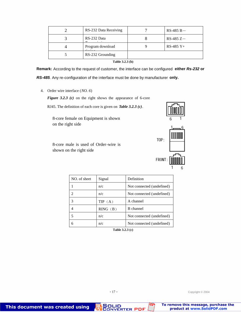
4. Order wire interface (NO. 6)
Figure 3.2.3 (c) on the right shows the appearance of 6-core
RJ45. The definition of each core is given on Table 3.2.3 (c).
NO. of sheet Signal Definition
1 n/c Not connected (undefined)
2 n/c Not connected (undefined)
3 TIP(A) A channel
4 RING(B) B channel
5 n/c Not connected (undefined)
6 n/c Not connected (undefined)
Table 3.2.3 (c)
8-core female on Equipment is shownon the right side
8-core male is used of Order-wire isshown on the right side
- 18 - Copyright © 2004
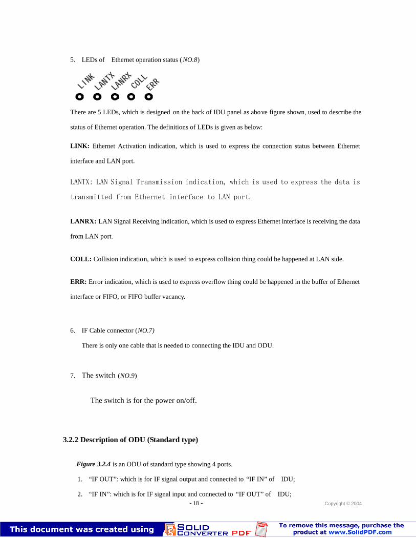
5. LEDs of Ethernet operation status ( NO.8)
There are 5 LEDs, which is designed on the back of IDU panel as above figure shown, used to describe the
status of Ethernet operation. The definitions of LEDs is given as below:
LINK: Ethernet Activation indication, which is used to express the connection status between Ethernet
interface and LAN port.
LANTX: LAN Signal Transmission indication, which is used to express the data is
transmitted from Ethernet interface to LAN port.
LANRX: LAN Signal Receiving indication, which is used to express Ethernet interface is receiving the data
from LAN port.
COLL: Collision indication, which is used to express collision thing could be happened at LAN side.
ERR: Error indication, which is used to express overflow thing could be happened in the buffer of Ethernet
interface or FIFO, or FIFO buffer vacancy.
6. IF Cable connector (NO.7)
There is only one cable that is needed to connecting the IDU and ODU.
7. The switch (NO.9)
The switch is for the power on/off.
3.2.2 Description of ODU (Standard type)
Figure 3.2.4 is an ODU of standard type showing 4 ports.
1. “IF OUT”: which is for IF signal output and connected to “IF IN” of IDU;
2. “IF IN”: which is for IF signal input and connected to “IF OUT” of IDU;
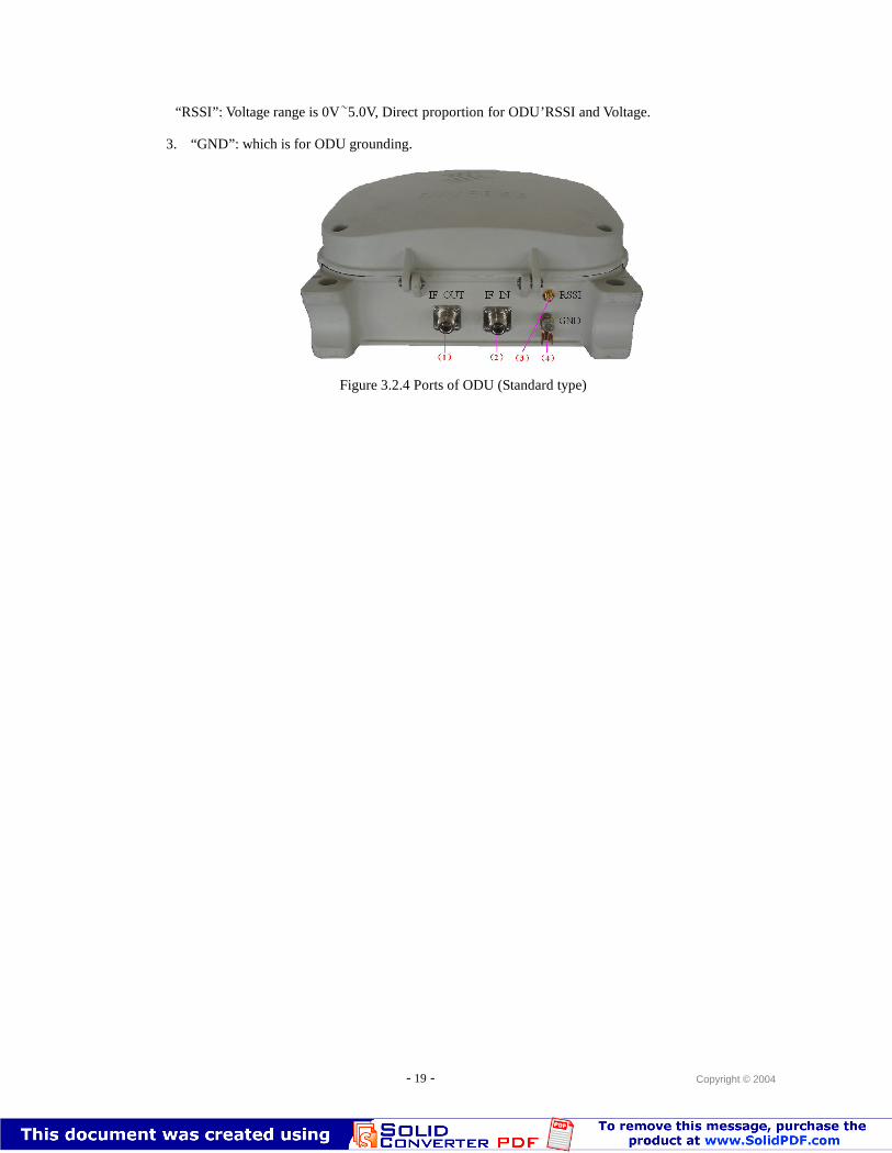
- 19 - Copyright © 2004
“RSSI”: Voltage range is 0V~5.0V, Direct proportion for ODU’RSSI and Voltage.
3. “GND”: which is for ODU grounding.
IF INIF OUT RSSI
GND
(1) (2) (3) (4)
Figure 3.2.4 Ports of ODU (Standard type)
- 20 - Copyright © 2004
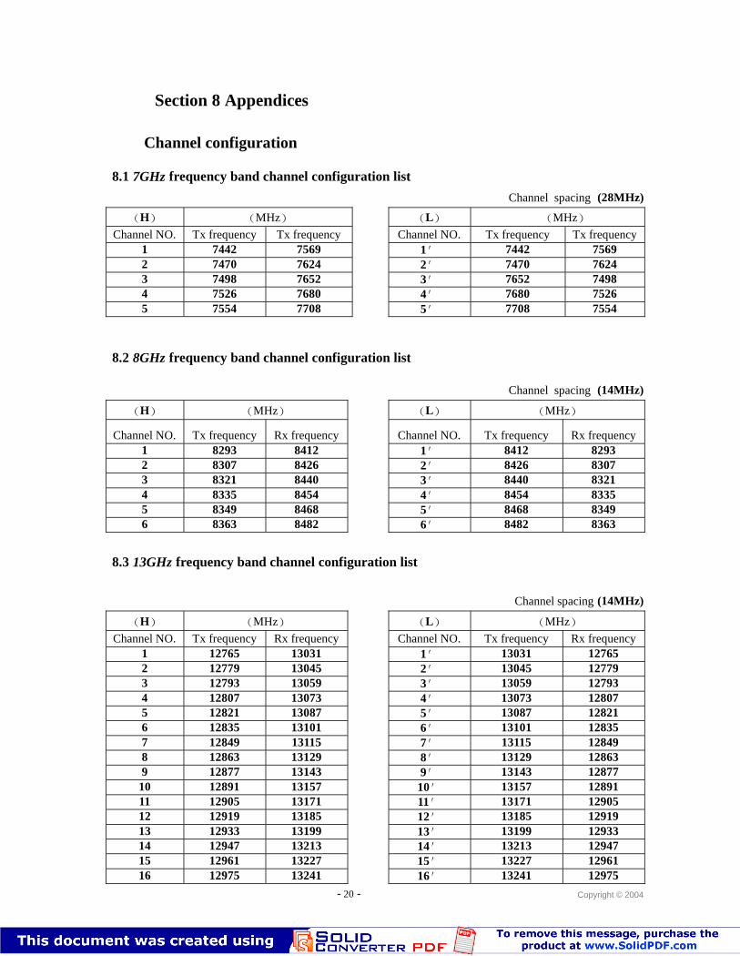
Section 8 Appendices
Channel configuration
8.1 7GHz frequency band channel configuration list
Channel spacing (28MHz)
(H) (MHz) (L) (MHz)Channel NO. Tx frequency Tx frequency Channel NO. Tx frequency Tx frequency
1 7442 7569 1′ 7442 75692 7470 7624 2′ 7470 76243 7498 7652 3′ 7652 74984 7526 7680 4′ 7680 75265 7554 7708 5′ 7708 7554
8.2 8GHz frequency band channel configuration list
Channel spacing (14MHz)
(H) (MHz) (L) (MHz)
Channel NO. Tx frequency Rx frequency Channel NO. Tx frequency Rx frequency1 8293 8412 1′ 8412 82932 8307 8426 2′ 8426 83073 8321 8440 3′ 8440 83214 8335 8454 4′ 8454 83355 8349 8468 5′ 8468 83496 8363 8482 6′ 8482 8363
8.3 13GHz frequency band channel configuration list
Channel spacing (14MHz)
(H) (MHz) (L) (MHz)Channel NO. Tx frequency Rx frequency Channel NO. Tx frequency Rx frequency
1 12765 13031 1′ 13031 127652 12779 13045 2′ 13045 127793 12793 13059 3′ 13059 127934 12807 13073 4′ 13073 128075 12821 13087 5′ 13087 128216 12835 13101 6′ 13101 128357 12849 13115 7′ 13115 128498 12863 13129 8′ 13129 128639 12877 13143 9′ 13143 12877
10 12891 13157 10′ 13157 1289111 12905 13171 11′ 13171 1290512 12919 13185 12′ 13185 1291913 12933 13199 13′ 13199 1293314 12947 13213 14′ 13213 1294715 12961 13227 15′ 13227 1296116 12975 13241 16′ 13241 12975
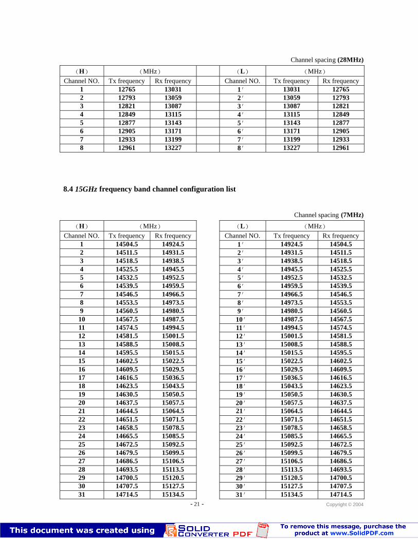
- 21 - Copyright © 2004
Channel spacing (28MHz)
(H) (MHz) (L) (MHz)Channel NO. Tx frequency Rx frequency Channel NO. Tx frequency Rx frequency
1 12765 13031 1′ 13031 127652 12793 13059 2′ 13059 127933 12821 13087 3′ 13087 128214 12849 13115 4′ 13115 128495 12877 13143 5′ 13143 128776 12905 13171 6′ 13171 129057 12933 13199 7′ 13199 129338 12961 13227 8′ 13227 12961
8.4 15GHz frequency band channel configuration list
Channel spacing (7MHz)
(H) (MHz) (L) (MHz)Channel NO. Tx frequency Rx frequency Channel NO. Tx frequency Rx frequency
1 14504.5 14924.5 1′ 14924.5 14504.52 14511.5 14931.5 2′ 14931.5 14511.53 14518.5 14938.5 3′ 14938.5 14518.54 14525.5 14945.5 4′ 14945.5 14525.55 14532.5 14952.5 5′ 14952.5 14532.56 14539.5 14959.5 6′ 14959.5 14539.57 14546.5 14966.5 7′ 14966.5 14546.58 14553.5 14973.5 8′ 14973.5 14553.59 14560.5 14980.5 9′ 14980.5 14560.5
10 14567.5 14987.5 10′ 14987.5 14567.511 14574.5 14994.5 11′ 14994.5 14574.512 14581.5 15001.5 12′ 15001.5 14581.513 14588.5 15008.5 13′ 15008.5 14588.514 14595.5 15015.5 14′ 15015.5 14595.515 14602.5 15022.5 15′ 15022.5 14602.516 14609.5 15029.5 16′ 15029.5 14609.517 14616.5 15036.5 17′ 15036.5 14616.518 14623.5 15043.5 18′ 15043.5 14623.519 14630.5 15050.5 19′ 15050.5 14630.520 14637.5 15057.5 20′ 15057.5 14637.521 14644.5 15064.5 21′ 15064.5 14644.522 14651.5 15071.5 22′ 15071.5 14651.523 14658.5 15078.5 23′ 15078.5 14658.524 14665.5 15085.5 24′ 15085.5 14665.525 14672.5 15092.5 25′ 15092.5 14672.526 14679.5 15099.5 26′ 15099.5 14679.527 14686.5 15106.5 27′ 15106.5 14686.528 14693.5 15113.5 28′ 15113.5 14693.529 14700.5 15120.5 29′ 15120.5 14700.530 14707.5 15127.5 30′ 15127.5 14707.531 14714.5 15134.5 31′ 15134.5 14714.5
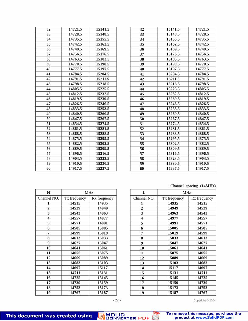
- 22 - Copyright © 2004
32 14721.5 15141.5 32′ 15141.5 14721.533 14728.5 15148.5 33′ 15148.5 14728.534 14735.5 15155.5 34′ 15155.5 14735.535 14742.5 15162.5 35′ 15162.5 14742.536 14749.5 15169.5 36′ 15169.5 14749.537 14756.5 15176.5 37′ 15176.5 14756.538 14763.5 15183.5 38′ 15183.5 14763.539 14770.5 15190.5 39′ 15190.5 14770.540 14777.5 15197.5 40′ 15197.5 14777.541 14784.5 15204.5 41′ 15204.5 14784.542 14791.5 15211.5 42′ 15211.5 14791.543 14798.5 15218.5 43′ 15218.5 14798.544 14805.5 15225.5 44′ 15225.5 14805.545 14812.5 15232.5 45′ 15232.5 14812.546 14819.5 15239.5 46′ 15239.5 14819.547 14826.5 15246.5 47′ 15246.5 14826.548 14833.5 15253.5 48′ 15253.5 14833.549 14840.5 15260.5 49′ 15260.5 14840.550 14847.5 15267.5 50′ 15267.5 14847.551 14854.5 15274.5 51′ 15274.5 14854.552 14861.5 15281.5 52′ 15281.5 14861.553 14868.5 15288.5 53′ 15288.5 14868.554 14875.5 15295.5 54′ 15295.5 14875.555 14882.5 15302.5 55′ 15302.5 14882.556 14889.5 15309.5 56′ 15309.5 14889.557 14896.5 15316.5 57′ 15316.5 14896.558 14903.5 15323.5 58′ 15323.5 14903.559 14910.5 15330.5 59′ 15330.5 14910.560 14917.5 15337.5 60′ 15337.5 14917.5
Channel spacing (14MHz)
(H) (MHz) (L) (MHz)Channel NO. Tx frequency Rx frequency Channel NO. Tx frequency Rx frequency
1 14515 14935 1′ 14935 145152 14529 14949 2′ 14949 145293 14543 14963 3′ 14963 145434 14557 14977 4′ 14977 145575 14571 14991 5′ 14991 145716 14585 15005 6′ 15005 145857 14599 15019 7′ 15019 145998 14613 15033 8′ 15033 146139 14627 15047 9′ 15047 14627
10 14641 15061 10′ 15061 1464111 14655 15075 11′ 15075 1465512 14669 15089 12′ 15089 1466913 14683 15103 13′ 15103 1468314 14697 15117 14′ 15117 1469715 14711 15131 15′ 15131 1471116 14725 15145 16′ 15145 1472517 14739 15159 17′ 15159 1473918 14753 15173 18′ 15173 1475319 14767 15187 19′ 15187 14767
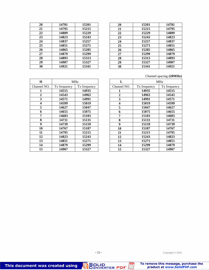
- 23 - Copyright © 2004
20 14781 15201 20′ 15201 1478121 14795 15215 21′ 15215 1479522 14809 15229 22′ 15229 1480923 14823 15243 23′ 15243 1482324 14837 15257 24′ 15257 1483725 14851 15271 25′ 15271 1485126 14865 15285 26′ 15285 1486527 14879 15299 27′ 15299 1487928 14893 15313 28′ 15313 1489329 14907 15327 29′ 15327 1490730 14921 15341 30′ 15341 14921
Channel spacing (28MHz)
(H) (MHz) (L) (MHz)Channel NO. Tx frequency Tx frequency Channel NO. Tx frequency Tx frequency
1 14515 14935 1′ 14935 145152 14543 14963 2′ 14963 145433 14571 14991 3′ 14991 145714 14599 15019 4′ 15019 145995 14627 15047 5′ 15047 146276 14655 15075 6′ 15075 146557 14683 15103 7′ 15103 146838 14711 15131 8′ 15131 147119 14739 15159 9′ 15159 14739
10 14767 15187 10′ 15187 1476711 14795 15215 11′ 15215 1479512 14823 15243 12′ 15243 1482313 14851 15271 13′ 15271 1485114 14879 15299 14′ 15299 1487915 14907 15327 15′ 15327 14907
- 24 - Copyright © 2004
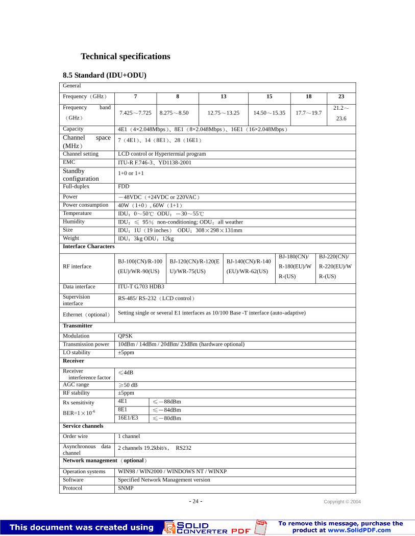
Technical specifications
8.5 Standard (IDU+ODU)General
Frequency(GHz) 7 8 13 15 18 23
Frequency band
(GHz)7.425~7.725 8.275~8.50 12.75~13.25 14.50~15.35 17.7~19.7
21.2~
23.6
Capacity 4E1(4×2.048Mbps)、8E1(8×2.048Mbps)、16E1(16×2.048Mbps)
Channel space(MHz)
7(4E1)、14(8E1)、28(16E1)
Channel setting LCD control or Hypertermial program
EMC ITU-R F.746-3、YD1138-2001
Standbyconfiguration
1+0 or 1+1
Full-duplex FDD
Power -48VDC(+24VDC or 220VAC)Power consumption 40W(1+0), 60W(1+1)Temperature IDU:0~50℃ ODU:-30~55℃Humidity IDU:≤ 95% non-conditioning; ODU:all weatherSize IDU:1U(19 inches) ODU:308×298×131mmWeight IDU:3kg ODU:12kgInterface Characters
RF interfaceBJ-100(CN)/R-100
(EU)/WR-90(US)
BJ-120(CN)/R-120(E
U)/WR-75(US)
BJ-140(CN)/R-140
(EU)/WR-62(US)
BJ-180(CN)/
R-180(EU)/W
R-(US)
BJ-220(CN)/
R-220(EU)/W
R-(US)
Data interface ITU-T G.703 HDB3
Supervisioninterface
RS-485/ RS-232(LCD control)
Ethernet(optional) Setting single or several E1 interfaces as 10/100 Base -T interface (auto-adaptive)
Transmitter
Modulation QPSK
Transmission power 10dBm / 14dBm / 20dBm/ 23dBm (hardware optional)
LO stability ±5ppm
Receiver
Receiverinterference factor
≤4dB
AGC range ≥50 dBRF stability ±5ppm
4E1 ≤-88dBm8E1 ≤-84dBm
Rx sensitivity
BER=1×10⁻⁶
16E1/E3 ≤-80dBmService channels
Order wire 1 channel
Asynchronous datachannel
2 channels 19.2kbit/s, RS232
Network management(optional)
Operation systems WIN98 / WIN2000 / WINDOWS NT / WINXP
Software Specified Network Management version
Protocol SNMP
- 25 - Copyright © 2004
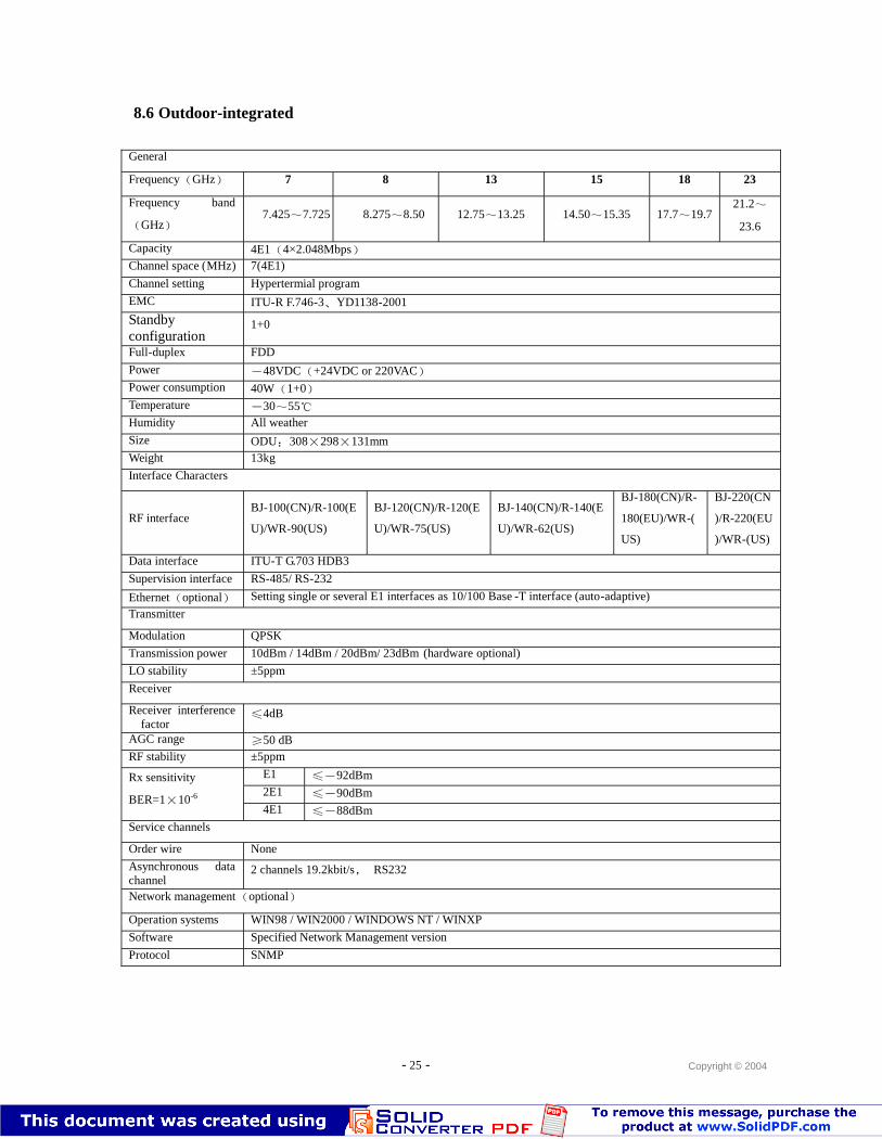
8.6 Outdoor-integrated
General
Frequency(GHz) 7 8 13 15 18 23
Frequency band
(GHz)7.425~7.725 8.275~8.50 12.75~13.25 14.50~15.35 17.7~19.7
21.2~
23.6
Capacity 4E1(4×2.048Mbps)Channel space (MHz) 7(4E1)
Channel setting Hypertermial program
EMC ITU-R F.746-3、YD1138-2001
Standbyconfiguration
1+0
Full-duplex FDD
Power -48VDC(+24VDC or 220VAC)Power consumption 40W(1+0)Temperature -30~55℃Humidity All weather
Size ODU:308×298×131mmWeight 13kg
Interface Characters
RF interfaceBJ-100(CN)/R-100(E
U)/WR-90(US)
BJ-120(CN)/R-120(E
U)/WR-75(US)
BJ-140(CN)/R-140(E
U)/WR-62(US)
BJ-180(CN)/R-
180(EU)/WR-(
US)
BJ-220(CN
)/R-220(EU
)/WR-(US)
Data interface ITU-T G.703 HDB3
Supervision interface RS-485/ RS-232
Ethernet(optional) Setting single or several E1 interfaces as 10/100 Base -T interface (auto-adaptive)
Transmitter
Modulation QPSK
Transmission power 10dBm / 14dBm / 20dBm/ 23dBm (hardware optional)
LO stability ±5ppm
Receiver
Receiver interferencefactor
≤4dB
AGC range ≥50 dBRF stability ±5ppm
E1 ≤-92dBm2E1 ≤-90dBm
Rx sensitivity
BER=1×10⁻⁶
4E1 ≤-88dBmService channels
Order wire None
Asynchronous datachannel
2 channels 19.2kbit/s, RS232
Network management(optional)
Operation systems WIN98 / WIN2000 / WINDOWS NT / WINXP
Software Specified Network Management version
Protocol SNMP