Embed Size (px)
Citation preview
WaveStar™ AM 1Add/Drop Multiplexer
User Guide
365-372-201Issue 1November 1999

Copyright© 1999 Lucent TechnologiesAll Rights ReservedPrinted in U.S.A.
This material is protected by the copyright and trade secret laws of the United States and other countries. It may not be reproduced, distributed or altered in any fashion by any entity (either internal or external to Lucent Technologies), except in accordance with applicable agreements, contracts, or licensing, without the express written consent of the Customer Training and Information Products organization and the business management owner of the material.
For permission to reproduce or distribute please contact your Lucent Technologies Account Executive.
NoticeThe information in this document is subject to change without notice. Although every effort was made to ensure that the information in this document was accurate, complete and clear as possible, Lucent Technologies Inc. and its predecessors assume no responsibility for any errors that may appear in this document.
Trademarks5ESS, LGX, and ST are registered trademarks of Lucent Technologies Inc.American Express is a registered trademark of American Express Company.IMB is a registered trademark of International Business Machines Corporation.MasterCard is a registered trademark of MasterCard International Incorporated. VISA is a registered trademark of VISA International Service Association.WaveStar is a trademark of Lucent Technologies Inc.Windows, Windows NT and Microsoft are registered trademarks of Microsoft Corporation.
WarrantyFor warranty information refer to the “Standard Warranty” section.
Product SupportFor a list of product support telephone numbers and/or web sites refer to the “Product Support” section.
This document was developed for the Lucent Technologies Optical Networking Group (ONG) by the Customer Training and Information Products (CTIP) organization.
Issue 1 November 1999 iii
365-372-201WaveStar AM 1 User Guide - Table of Contents
About This Document ....................................................... 1Intended Audience ......................................................... 1Reason for Issue ............................................................ 1Before Installing Product ................................................ 1User Guide Overview ..................................................... 2
SECTION I .......................................................................... 2System Description ............................................................ 2
Features ......................................................................... 3Hardware Description..................................................... 4Hardware Illustration ...................................................... 5Technical Specifications................................................. 9
Optical Interface .................................................... 9Tributary Interface ................................................. 9Supervision Interfaces ........................................... 9Synchronization ................................................... 10Mapping............................................................... 10Power Specifications ........................................... 10Equipment Dimensions........................................ 11Environmental Conditions.................................... 11Performance Monitoring ...................................... 11
Safety Instructions ........................................................... 12Laser Safety Information .............................................. 20
General Laser Information................................... 20Lasers and Eye Damage ..................................... 20Classification of Lasers........................................ 21Lightwave Safety Precautions ............................. 22Safety Precautions for Enclosed Systems........... 22Safety Precautions for Unenclosed Systems ...... 23
Installation Instructions ................................................. 25Environmental Considerations ..................................... 25Wall Mounting the Unit ................................................. 25Rack Mounting the Unit ................................................ 26
iv Issue 1 November 1999
365-372-201WaveStar AM 1 User Guide - Table of Contents
Connecting Power ........................................................ 27Grounding Option................................................. 28Powering from AC/DC Converters ....................... 28Powering from DC/DC Converters....................... 28
Connecting STM-1 Fibers............................................. 28Connecting E1 Tributaries ............................................ 29Connecting E3 Tributaries (optional) ............................ 29MDI/MDO Connections................................................. 29
Synchronization and Timing ......................................... 30Synchronization ................................................... 30SYNC-OUT .......................................................... 30Terminal Configuration......................................... 30Timing Modes ...................................................... 31
Transmission Protection ................................................. 32SNC/N Protection................................................. 321+1 MSP Protection............................................. 32
Operations.......................................................................... 33Operations Interfaces and Administration .................... 33Maintenance Supervision ............................................. 34System Alarm Indicators............................................... 35Software Maintenance.................................................. 35Maintenance Testing .................................................... 35Performance Monitoring ............................................... 36Self-Diagnostics and Recovery .................................... 37Miscellaneous Discrete Inputs & Outputs..................... 37LEDs Normal Operation ............................................... 38Software Upgrades....................................................... 38
Troubleshooting................................................................ 39Connector and Fiber Cleaning ............................. 41Power Supply....................................................... 41
Product Support ............................................................... 42Technical Assistance.................................................... 42
Issue 1 November 1999 v
365-372-201WaveStar AM 1 User Guide - Table of Contents
Warranty....................................................................... 43Discontinued Availability ...................................... 43
Standard Repair ........................................................... 43Repair Interval ..................................................... 43Out-Of-Warranty Provisions ................................ 44International Repair and Service ......................... 44
SECTION II ....................................................................... 47Equipment Provisioning ................................................. 47
Creating a Node ........................................................... 47Windows for Creating a Node.............................. 48Parameters for Creating a Node.......................... 50Create a Node ..................................................... 52
Provisioning Slots......................................................... 53Windows for Provisioning Slots ........................... 53Parameters for Provisioning Slots ....................... 55Provision Slots..................................................... 57
Confirming the MIB ...................................................... 58Window for Confirming the MIB........................... 59Parameters for Confirming the MIB ..................... 59Confirm the MIB................................................... 63
Viewing NE Slot Information ........................................ 64Windows for Viewing NE Slot Information ........... 64Parameters for Viewing NE Slot Information ....... 65View NE Slot Information..................................... 67
Viewing Hardware Inventory ........................................ 68Windows for Viewing Hardware Inventory........... 68Parameters for Viewing Hardware Inventory....... 70View Hardware Inventory - Shelf ......................... 71View Hardware Inventory - Slot ........................... 72
Viewing and Editing Node Details ................................ 73Windows for Viewing and Editing Node Details... 74Parameters for Viewing and Editing Node Details.................................................................. 75
vi Issue 1 November 1999
365-372-201WaveStar AM 1 User Guide - Table of Contents
View and Edit Node Details ................................. 78Viewing and Editing MDI Information ........................... 79
Windows for Viewing and Editing MDI Information ........................................................... 79Parameters for Viewing and Editing MDI Information ........................................................... 80View and Edit MDI Information ............................ 81
Viewing and Editing MDO Information.......................... 81Windows for Viewing and Editing MDO Information ........................................................... 82Parameters for Viewing and Editing MDO Information ........................................................... 83View and Edit MDO Information........................... 83
Transmission Provisioning ............................................. 85Provision Cross Connections ....................................... 86
Parameters for Provisioning Cross Connections ......................................................... 87Windows for Cross Connection Information and Selection .............................................................. 88Windows for Provisioning Cross Connections ..... 89Procedure to Add Cross Connections.................. 91Procedure to Modify Existing Cross Connections ......................................................... 93Procedure to Delete an Existing Cross Connection........................................................... 94
Provision TUG Structure............................................... 95Parameters for Provisioning TUG Structure ........ 96Windows for Provisioning the TUG Structure ...... 97Procedure for Provisioning the TUG Structure .... 99
Port Provisioning ........................................................ 100Parameters for Port Provisioning ....................... 101Windows for Port Information and Port Selection ............................................................ 103
Issue 1 November 1999 vii
365-372-201WaveStar AM 1 User Guide - Table of Contents
Windows for Provisioning 2 Mbit/s Ports ........... 105Windows for Provisioning 34 Mbit/s Ports ......... 105Windows for Provisioning STM-1 Ports ............. 106Procedure for Port Provisioning......................... 107
Provisioning Termination Points................................. 108Parameters for Provisioning Termination Points................................................................. 109Windows for Provisioning Termination Points ... 110Procedure for Provisioning Termination Points . 113
Path Trace Provisioning ............................................. 114Parameters for Path Trace Provisioning............ 114Windows used for Path Trace Provisioning....... 117Procedure to Provision a Path Trace................. 118
Provision Degraded Signal Thresholds ...................... 120Parameters for Provisioning Degraded Signal Thresholds......................................................... 120Windows used for Provisioning Degraded Signal Thresholds.............................................. 121Procedure to Change the Threshold for a Signal................................................................. 122
Transmission Protection............................................... 125View SNC Protection.................................................. 125
Parameters for Viewing SNC Protection ........... 125Windows for Viewing SNC Protection ............... 127View SNC Protection ......................................... 129
Edit SNC Protection ................................................... 130Parameters for Editing SNC Protection ............. 130Windows for Editing SNC Protection ................. 130Edit SNC Protection........................................... 132
Switch SNC Protection............................................... 132Parameters for Switching SNC Protection......... 133Windows for Switching SNC Protection............. 134Switching SNC Protection ................................. 135
viii Issue 1 November 1999
365-372-201WaveStar AM 1 User Guide - Table of Contents
View and Edit MSP Protection.................................... 136Parameters for Viewing and Editing MSP Protection........................................................... 137Windows for Viewing and Editing MSP Protection........................................................... 139View and Edit MSP Protection ........................... 141
Switch MSP Protection ............................................... 141Parameters for Switching MSP Protection......... 142Windows for Switching MSP Protection............. 144Switch MSP Protection ...................................... 145
Add MSP Protection ................................................... 145Parameters for Adding MSP Protection ............. 146Windows for Adding MSP Protection ................. 147Add MSP Protection........................................... 149
Timing Provisioning ...................................................... 151Provision Timing Sources........................................... 151
Parameters to Provision Timing Sources........... 152Windows to Provision Timing Sources............... 156Provision Timing Sources .................................. 158
Provision System Timing ............................................ 162Parameters to Provision System Timing............ 163Windows to Provision System Timing................ 168Provision System Timing ................................... 170
Provision Station Clock Output................................... 173Parameters to Provision Station Clock Output... 173Windows to Provision Station Clock Output....... 178Provision Station Clock Output .......................... 181
Provision Output Port Timing...................................... 184Parameters to Provision Output Port Timing ..... 185Windows to Provision Output Port Timing ......... 188Provision Output Port Timing ............................. 189
Issue 1 November 1999 1
WaveStar™ AM 1 User Guide
About This Document
Intended Audience
The WaveStar™ AM 1 Add/Drop Multiplexer User Guide is written primarily for end users responsible for installation, operations, and maintenance of the WaveStar™ AM 1. In addition, others needing specific information about the features, operations, and engineering of the WaveStar™ AM 1 may find the information in this User Guide useful.
Reason for Issue
This User Guide, Issue 1, provides technical, installation, and oper-ational instructions for the WaveStar™ AM 1. It has been issued for Release 1.0.
Before Installing Product
It is recommended that the user read through Section I of this docu-ment before installing the WaveStar™ AM 1 Multiplexer.
2 Issue 1 November 1999
365-372-201WaveStar™ AM 1 User Guide
User Guide Overview
This User Guide is divided into two sections:
Section I contains information on the following:
System Description
Safety Instructions
Installation Instructions
Synchronization and Timing
Transmission Protection
Operations
Troubleshooting
Product Support
Section II contains information and instructions on provision-ing the equipment, transmission, protection and timing of the WaveStar™ AM 1 using ITM-CIT software.
SECTION I
System Description
The WaveStar™ AM 1 is an SDH STM-1 Add/Drop Multiplexer opti-mized to provide various 2 Mbit/s and 34 Mbit/s services to busi-ness customers. The WaveStar™ AM 1 is an STM-1 Multiplexer able to multiplex plesiochronous tributary signals into a 155 Mbit/s STM-1 optical aggregate signal.
In the Access Network, the WaveStar™ AM 1 can be installed at the customer premises for fiber-to-the-business applications, enabling various ring or linear configurations. Other applications include LAN-to-LAN traffic on campus networks or WANs.
Issue 1 November 1999 3
365-372-201WaveStar™ AM 1 User Guide
Features
Key features of the WaveStar™ AM 1 include the following:
Basic sixteen 2.048 Mbit/s interface ports
Optional sixteen additional 2.048 Mbit/s interface ports
G.703 E1 physical interface
G.704/G.706 E1 interface
OR
Optional two additional 34.368 Mbit/s interface ports
G.703 E3 physical interface
Local software downloading
Remote software downloading
Performance Monitoring
Dual fiber working
Transmission protection: SNC/N, 1+1 MSP
Simple and rapid installation
Space-efficient for installations within environmentally con-trolled street cabinets or on customer premises
Supported by the user-friendly Integrated Transmission Management (ITM-SC, ITM-CIT) network management sys-tems
Optional AC/DC converter
Optional DC/DC converter
Optional battery backup
Optional 120 ohm to 75 ohm adapter.

4 Issue 1 November 1999
365-372-201WaveStar™ AM 1 User Guide
Hardware Description
The WaveStar™ AM 1 is a compact and cost-effective STM-1 multi-plexer designed to be installed at the customer’s premises for fiber-to-the-business applications. Its space-efficient design allows for wall-mounting within controlled environment locations (e.g. interior closet). At 250 x 375 x 33 mm (H x W x D ),* the basic lockable wall-mounted unit contains the following:
WaveStar™ AM 1 main board assembly
Two STM-1 optical line interface pair (transmit/receive) with type SC connectors
Sixteen 2.048 Mbit/s electrical tributary interfaces with RJ45 jacks suitable for symmetrical twisted pair cables with an impedance of 120 Ω
F-interface (RJ45) for the Craft Interface Terminal (ITM-CIT)
LAN Q-Interface (LAN-10baseT) Ethernet
Timing output for 2 Mbit/s synchronization (SYNC-OUT)
Dual Power Feed via a protected terminal block (Note: To be powered only by Safety Extra Low Voltage (SELV) -48 VDC or -60 VDC sources.)
Two LEDs (Red, Green) to indicate the status of the unit
Four Miscellaneous Discrete Input (MDI) ports
Four Miscellaneous Discrete Output (MDO) ports
* The depth of the unit (D) increases to 55 mm with either option card.
Issue 1 November 1999 5
365-372-201WaveStar™ AM 1 User Guide
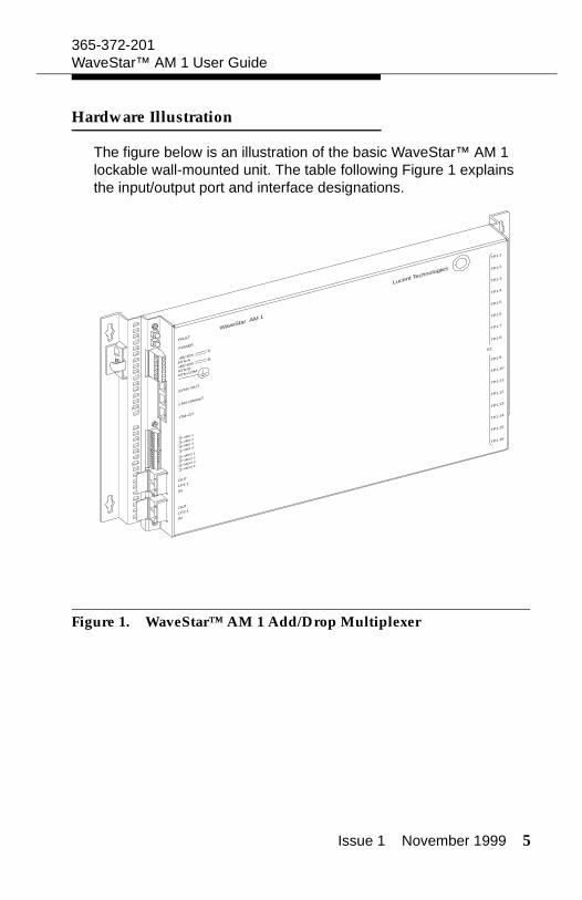
Hardware Illustration
The figure below is an illustration of the basic WaveStar™ AM 1 lockable wall-mounted unit. The table following Figure 1 explains the input/output port and interface designations.
Figure 1. WaveStar™ AM 1 Add/Drop Multiplexer
FAULT
POWER
-48/-60VA
BRTN A
-48/-60V
OUT
OUT
RTN B
LP1.1
LP2.1
TP1.2
TP1.10
TP1.3
TP1.11
TP1.4
TP1.12
TP1.5
TP1.13
TP1.6
TP1.14
TP1.7
TP1.15
TP1.8
TP1.16
TP1.1
Lucent Technologies
WaveStar AM 1
TP1.9
E1
RTN COM
IN
IN
SYNC-OUT
LAN-10baseT
ITM-CIT
MDI 1
MDO 1
MDI 2
MDO 2
MDI 3
MDO 3
MDI 4
MDO 4
6 Issue 1 November 1999
365-372-201WaveStar™ AM 1 User Guide
Table 1. WaveStar™ AM 1 Port and Interface Designations
Table 1 describes the WaveStar™ AM 1’s designations pictured in Figure 1. Also listed are designations for the E1 and E3 option cards (not shown). All pinouts are looking into the connectors.
AM 1 Designation
Description Physical Description
Pinout
<OUT><LP1.1>
<IN>
STM-1 Optical Output & Input for Line Port 1
SC Connector
<OUT><LP2.1>
<IN>
STM-1 Optical Output & Input for Line Port 2
SC Connector
E1 PORTS<TP1.1—TP1.16>
With option E1s <TP2.1—TP2.16>
2.048 Mbit/s E1 Inputs and Out-puts
RJ45 connec-tors wired per RJ48C stan-dard with metal shell for ground-ing
1 = TX-R 2 = TX-T 4 = RX-R5 = RX-T3, 6_8 = NC(See NOTE 2)
E3 PORTSWith optional E3s<TP1.1—TP1.2>
34.368 Mbit/s E3 Inputs and Outputs
DIN 1.6/5.6 coaxial connec-tors
<SYNC-OUT> 2048 kHz Timing Output(station clock output)
RJ45 connector with metal shell for grounding — 120 ohm symmetrical
1 = R1 (XMT-)2 = T1 (XMT+)3, 8 = NC(See NOTE 3)
<LAN-10baseT> LAN-Q Interface Ethernet access port
RJ45 connector with metal shell for grounding
1 = P (XMT)2 = N (XMT)3 = P (RCV)6 = N (RCV)4, 5, 7, 8 = NC
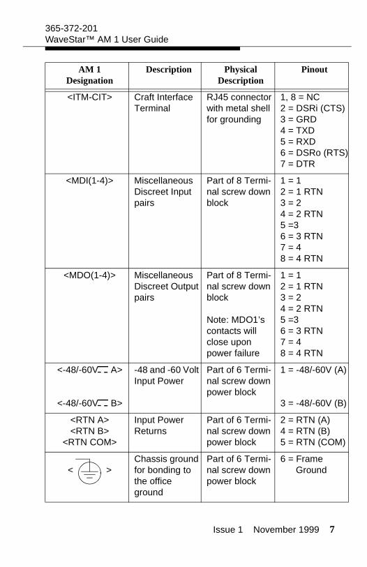
Issue 1 November 1999 7
365-372-201WaveStar™ AM 1 User Guide
<ITM-CIT> Craft Interface Terminal
RJ45 connector with metal shell for grounding
1, 8 = NC2 = DSRi (CTS)3 = GRD4 = TXD5 = RXD6 = DSRo (RTS)7 = DTR
<MDI(1-4)> Miscellaneous Discreet Input pairs
Part of 8 Termi-nal screw down block
1 = 12 = 1 RTN3 = 24 = 2 RTN5 =36 = 3 RTN7 = 48 = 4 RTN
<MDO(1-4)> Miscellaneous Discreet Output pairs
Part of 8 Termi-nal screw down block
Note: MDO1’s contacts will close upon power failure
1 = 12 = 1 RTN3 = 24 = 2 RTN5 =36 = 3 RTN7 = 48 = 4 RTN
<-48/-60V A>
<-48/-60V B>
-48 and -60 Volt Input Power
Part of 6 Termi-nal screw down power block
1 = -48/-60V (A)
3 = -48/-60V (B)
<RTN A><RTN B>
<RTN COM>
Input Power Returns
Part of 6 Termi-nal screw down power block
2 = RTN (A)4 = RTN (B)5 = RTN (COM)
< >Chassis ground for bonding to the office ground
Part of 6 Termi-nal screw down power block
6 = Frame Ground
AM 1 Designation
Description Physical Description
Pinout
8 Issue 1 November 1999
365-372-201WaveStar™ AM 1 User Guide
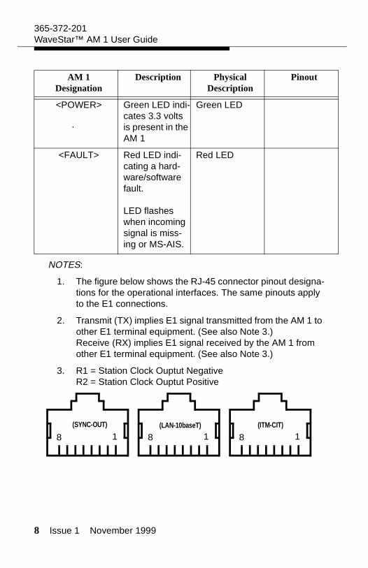
NOTES:
1. The figure below shows the RJ-45 connector pinout designa-tions for the operational interfaces. The same pinouts apply to the E1 connections.
2. Transmit (TX) implies E1 signal transmitted from the AM 1 to other E1 terminal equipment. (See also Note 3.)Receive (RX) implies E1 signal received by the AM 1 from other E1 terminal equipment. (See also Note 3.)
3. R1 = Station Clock Ouptut NegativeR2 = Station Clock Ouptut Positive
<POWER> Green LED indi-cates 3.3 volts is present in the AM 1
Green LED
<FAULT> Red LED indi-cating a hard-ware/software fault.
LED flashes when incoming signal is miss-ing or MS-AIS.
Red LED
AM 1 Designation
Description Physical Description
Pinout
(SYNC-OUT) (ITM-CIT)
8 1(LAN-10baseT)
8 1 8 1
Issue 1 November 1999 9
365-372-201WaveStar™ AM 1 User Guide
Technical Specifications
Optical Interface
A 155.52 Mbit/s G.957/S-1.1 short-haul optical interface with an attenuation range from 0 to 12 dB (1x10⁻¹⁰ BER sensitiv-ity) at an operating wavelength of 1310 nm.
Mean launch power of -8 dBm max, -15 dBm min
Minimum receiver sensitivity (BER ≤ 1x10⁻¹⁰) of -28 dBm
The STM-1 optical access is via SC-type connectors.
Tributary Interface
Interface at 2.048 Mbit/s ± 50 ppm, HDB3 coded and con-forming to G.703, asynchronously mapped via VC-12 in TU-12.
The 2 Mbit/s electrical interface access is via a RJ45 con-nector suitable for symmetrical twisted pair cables with an impedance of 120 Ω.
Interface at 34.368 Mbit/s, ± 20 ppm, clear channel HDB3 coded and conforming to G.703, asynchronously mapped via VC-3 in TU-3.
The 34.368 Mbit/s electrical interface access is via a coaxial DIN 1.6/5.6 type connector.
Supervision Interfaces
F-interface for Craft Interface Terminal (ITM-CIT) via RJ45 connector. The interface conforms to V.10/RS-232.
LAN Q-Interface (LAN-10baseT) via RJ45 connector.
10 Issue 1 November 1999
365-372-201WaveStar™ AM 1 User Guide
Synchronization
Timing according to ITU-T G.813, SDH equipment slave clock (SEC), option 1. Supports locked, hold-over, and free-running (accuracy of ± 4.6 ppm) modes.
Support of SSM byte.
Mapping
The WaveStar™ AM 1 supports mapping schemes for each VC12 and VC3 created and terminated in the system in accordance with ITU-T G.707:
E1: The WaveStar™ AM 1 supports an AU4 <-> VC4 <-> TUG3 <-> TUG2 <-> TU12 <-> VC12 mapping scheme for each VC12 created and terminated in the system.
E3: The WaveStar™ AM 1 supports an AU4 <-> VC4 <-> TUG3 <-> TU3 <-> VC3 mapping scheme for each VC3 cre-ated and terminated in the system.
Power Specifications
Input Voltage, -48/-60 VDC. To be powered only by Safety Extra Low Voltage (SELV) -48 VDC or -60 VDC sources.
Power consumption, less than 25 watts for basic unit, less than 50 watts with either option card
External 90-264V (47-63 Hz) AC/DC converter (optional)
External -24 to -48V DC/DC converter (optional)
-48 VDC battery backup (optional)
The system supports the grounding philosophy according to ETSI Requirements 300 253 (battery return connected to ground).
Issue 1 November 1999 11
365-372-201WaveStar™ AM 1 User Guide
Equipment Dimensions
Dimensions (H x W x D) 250 x 375 x 33 mm with basic unit (excluding mounting brackets)
Dimensions (H x W x D) 250 x 375 x 55 mm with either option card assembly (excluding mounting brackets)
Weight less than 5 Kg with either option card assembly
Environmental Conditions
Compliant with ETSI 300 019 Class 3.3.
ETSI EMC - The system meets the requirements of EN 300 386-2 for equipment installed in locations other than telecom centers
The system operates with convection cooling.
Performance Monitoring
Performance monitoring is in accordance with ITU-T G.826 and G.784.
The following four parameters are available to estimate the error performance of a path: SES, ES, BBE, and UAS
12 Issue 1 November 1999
365-372-201WaveStar™ AM 1 User Guide
Safety Instructions
IMPORTANT SAFETY INSTRUCTIONS
READ AND UNDERSTAND ALL INSTRUCTIONS
When installing, operating, or maintaining this equipment, basic safety precautions should always be followed to reduce the risk of fire, electric shock, and injury to persons, including the following:
1. Follow all warnings and instructions marked on this product.
2. To be powered only by a Safety Extra Low Voltage (SELV) -48V dc or -60V dc Sources.
3. Disconnect up to two (2) power supply connections when removing power from the system.
4. This product should be only operated from the type of power source indicated on the marking label.
5. Connect this product only to the type of power sources rec-ommended by Lucent Technologies. For information on the powering instructions, consult the Installation Instructions section of this User Guide.
The exclamation point within an equilateral triangle is intended to alert the user to the presence of important operating and maintenance (servicing) instructions in the literature accompanying this product.
!
Issue 1 November 1999 13
365-372-201WaveStar™ AM 1 User Guide
6. This equipment must be provided with a readily accessible disconnect device as part of the building installation.
7. Installation must include an independent frame ground drop to building ground.
8. This equipment is designed to permit the connection of the earthed conductor of the d.c. supply circuit to the earthing conductor at the equipment. If this connection is made, all of the following conditions must be met:
This equipment shall be connected directly to the d.c. supply system earthing electrode conductor, or to a bonding jumper from an earthing terminal bar or bus to which the d.c. supply system earthing electrode conductor is connected.
This equipment shall be located in the same immedi-ate area (such as; adjacent cabinets, frames, bays, etc.) as any other equipment that has a connection between the earthed conductor of the same d.c. sup-ply circuit and the earthing conductor, and also the point of earthing of the d.c. system. The d.c. system shall not be earthed elsewhere.
The d.c. supply source is to be located within the same premises as this equipment.
Switching or disconnecting devices shall not be in the earthed circuit conductor between the d.c. source and the point of connection of the earthing electrode con-ductor.
9. For information on proper mounting instructions, consult the Installation Instructions section of this User Guide.
10. Install only equipment identified in this User Guide. Use of other equipment may result in improper connection of cir-cuitry leading to fire or injury to persons.
14 Issue 1 November 1999
365-372-201WaveStar™ AM 1 User Guide
11. The telecommunication interfaces should not leave the build-ing premises unless connected to telecommunication devices providing primary and secondary protection, as applicable.
12. Do not use this product near water, for example, in a wet basement.
13. Do not place this product on an unstable cart, stand or table. The product may fall, causing serious damage to the prod-uct.
14. Use caution when installing or modifying telecommunica-tions lines.
15. Never install telecommunications wiring during a lightning storm.
16. Never install telecommunications connections in wet loca-tions.
17. Never touch uninsulated telecommunications wires or termi-nals unless the telecommunications line has been discon-nected at the network interface.
18. Never touch uninsulated wiring or terminals carrying direct current or ringing current, or leave this wiring exposed. Pro-tect and tape uninsulated wiring and terminals to avoid risk of fire, electric shock, and injury to service personnel.
19. Never push objects of any kind into this product through slots as they may touch dangerous voltage points or short out parts that could result in a risk of fire or electrical shock. Never spill liquids of any kind on the product.
20. To reduce the risk of an electrical shock, do not disassemble this product. Service should be performed by trained person-nel only. Opening or removing covers and/or circuit boards may expose you to dangerous voltages or other risks. Incor-rect reassembly can cause electrical shock when the unit is subsequently used.
Issue 1 November 1999 15
365-372-201WaveStar™ AM 1 User Guide
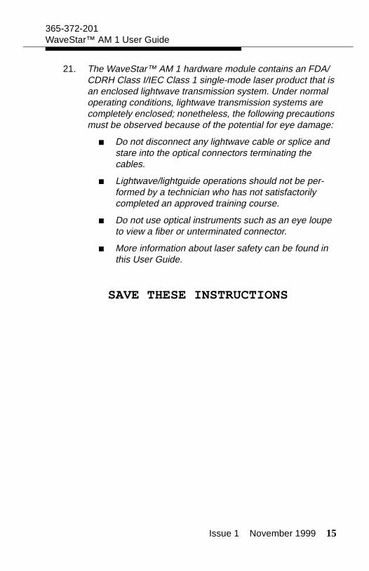
21. The WaveStar™ AM 1 hardware module contains an FDA/CDRH Class I/IEC Class 1 single-mode laser product that is an enclosed lightwave transmission system. Under normal operating conditions, lightwave transmission systems are completely enclosed; nonetheless, the following precautions must be observed because of the potential for eye damage:
Do not disconnect any lightwave cable or splice and stare into the optical connectors terminating the cables.
Lightwave/lightguide operations should not be per-formed by a technician who has not satisfactorily completed an approved training course.
Do not use optical instruments such as an eye loupe to view a fiber or unterminated connector.
More information about laser safety can be found in this User Guide.
SAVE THESE INSTRUCTIONS

16 Issue 1 November 1999
365-372-201WaveStar™ AM 1 User Guide
WICHTIGE SICHERHEITSANWEISUNGEN
BITTE ALLE ANWEISUNGEN SORGFÄLTIG DURCHLESEN
Nebenstehendes Symbol, ein Ausrufezeichen in einem Dreieck, weist den Benutzer darauf hin, daß sich unter den Unterlagen des Produktes bedeutende Betriebs- und Wartungsanweisungen befinden.
Bei Installation, Betrieb oder Wartung des vorliegenden Gerätes sollten immer grundlegende Sicherheitsanweisungen befolgt werden, um das Risiko eines Feuers, eines elektrischen Schocks oder anderer Verletzungen zu vermindern. Hierzu zählen vor allem:
1. Bitte alle auf diesem Produkt angegebenen Gefahrenhin-weise und Anleitungen befolgen.
2. Das Gerät darf nur von einer 48V GS-Sicherheits-Kleinspan-nung (SELV) oder einer 60V Sicherheitsstromspannung gespeist werden.
3. Bis zu 2 Speiseleitungen spannungsfrei machen, wenn das System ausgeschaltet wird.
4. Das Gerät nur an die Art von Stromspannung anschließen, die auf dem Produktschild angegeben ist.
5. Produkt nur an die von Lucent Technologies empfohlene Art der Stromversorgung anschließen. Nähere Auskünfte über die Netzstromanleitungen finden sich im Abschnitt Install-ierungsanweisungen des vorliegenden Benutzerhandbuchs.
!
Issue 1 November 1999 17
365-372-201WaveStar™ AM 1 User Guide
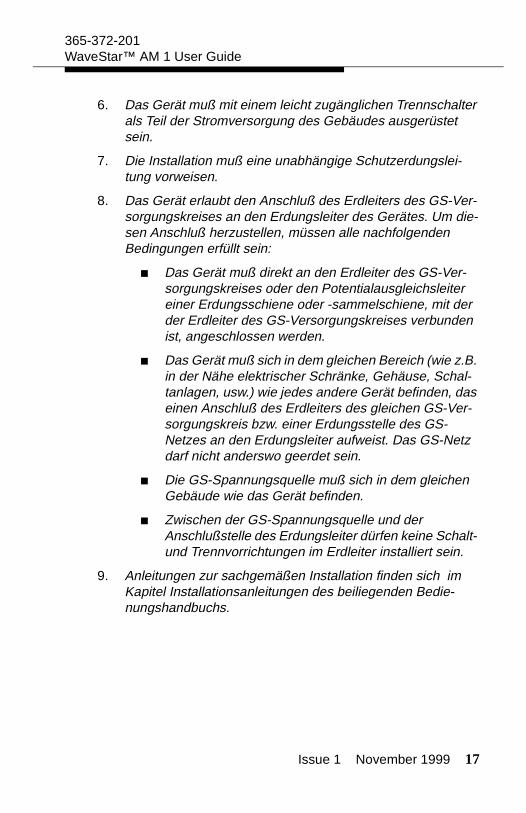
6. Das Gerät muß mit einem leicht zugänglichen Trennschalter als Teil der Stromversorgung des Gebäudes ausgerüstet sein.
7. Die Installation muß eine unabhängige Schutzerdungslei-tung vorweisen.
8. Das Gerät erlaubt den Anschluß des Erdleiters des GS-Ver-sorgungskreises an den Erdungsleiter des Gerätes. Um die-sen Anschluß herzustellen, müssen alle nachfolgenden Bedingungen erfüllt sein:
Das Gerät muß direkt an den Erdleiter des GS-Ver-sorgungskreises oder den Potentialausgleichsleiter einer Erdungsschiene oder -sammelschiene, mit der der Erdleiter des GS-Versorgungskreises verbunden ist, angeschlossen werden.
Das Gerät muß sich in dem gleichen Bereich (wie z.B. in der Nähe elektrischer Schränke, Gehäuse, Schal-tanlagen, usw.) wie jedes andere Gerät befinden, das einen Anschluß des Erdleiters des gleichen GS-Ver-sorgungskreis bzw. einer Erdungsstelle des GS-Netzes an den Erdungsleiter aufweist. Das GS-Netz darf nicht anderswo geerdet sein.
Die GS-Spannungsquelle muß sich in dem gleichen Gebäude wie das Gerät befinden.
Zwischen der GS-Spannungsquelle und der Anschlußstelle des Erdungsleiter dürfen keine Schalt- und Trennvorrichtungen im Erdleiter installiert sein.
9. Anleitungen zur sachgemäßen Installation finden sich im Kapitel Installationsanleitungen des beiliegenden Bedie-nungshandbuchs.

18 Issue 1 November 1999
365-372-201WaveStar™ AM 1 User Guide
10. Nur Ausrüstungsgegenstände installieren, die in beiliegen-dem Bedienungshandbuch angegeben sind. Die Verwend-ung anderer Gegenstände kann unsachgemäße Anschlüsse und Verbindungen zur Folge haben und somit zu Feuer und Verletzungen führen.
11. Die Telekommunikationsschnittstellen sollten nicht aus dem Gebäude herausführen, es sei denn sie sind an Telekommu-nikationsgeräte angeschlossen, die je nach Gerät mit primären und sekundären Schutzvorrichtungen ausgerüstet sind.
12. Das Produkt nicht in der Nähe von Wasser, z.B. in einem feuchten Kellergeschoß, verwenden.
13. Das Produkt nicht auf einen unstabilen Wagen, Stand oder Tisch legen. Es kann herunterfallen und ernsthaft beschädigt werden.
14. Vorsicht walten lassen, wenn Telekommunikationsleitungen installiert oder umverlegt werden.
15. Telekommunikationsleitungen niemals bei Blitz oder Unwet-ter installieren.
16. Telekommunikationsleitungen niemals an feuchten Plätzen installieren.
17. Niemals blanke Enden oder Anschlüsse von Telekommuni-kationsleitungen berühren, es sei denn die Leitungen wur-den vorher an der Netzschnittstelle abmontiert.
18. Niemals blanke Enden oder Anschlüsse berühren , die unter Gleich- oder Rufstrom stehen, oder diese Enden frei und offen lassen. Enden und Anschlüsse mit Isolierband abdich-ten, um das Risiko eines Feuers, eines elektrischen Schocks oder anderer Verletzungen zu vermeiden.
19. Niemals irgendwelche Gegenstände durch die Schlitze in das Gerät stecken, da sie unter Strom stehende Enden berühren oder Teile kurzschließen und somit die Gefahr

Issue 1 November 1999 19
365-372-201WaveStar™ AM 1 User Guide
eines Feuers oder eines elektrischen Schocks auslösen könnten. Niemals irgendwelche Flüssigkeiten über dem Gerät verschütten.
20. Um das Risiko eines elektrischen Schocks zu vermindern, dieses Produkt nicht auseinandermontieren. Die Wartung sollte nur von Fachpersonal vorgenommen werden. Das Offenlegen und Entfernen von Deckeln und/oder Leiterplat-ten kann zum Kontakt mit gefährlichen Spannungen führen oder andere Gefahren nach sich ziehen. Nicht ordnungs-gemäßes Zusammenmontieren kann elektrische Schocks zur Folge haben, wenn das Gerät später benutzt wird.
21. Das WaveStar TM 1 Hardwaremodul enthält ein Mono-mode-Laserprodukt der FDA/CDRH Klasse I/IEC Klasse I, welches ein gekapselter Lichtwellenleiter ist. In der Regel sind Lichtwellenleiter vollständig umhüllt. Um Risiken einer Augenverletzung vorzubeugen, sollten jedoch folgende Vor-sichtsmaßnahmen getroffen werden:
Lichtwellenleiterkabel nicht abmontieren oder spleißen und die Steckverbindungen am Ende der Kabel genau betrachten.
Arbeiten mit Lichtwellenleiter sollten nur von Fachper-sonal vorgenommen werden, das eine Qualifizierung auf diesem Gebiet vorweisen kann.
Keine optischen Instrumente wie z.B. eine Lupe benutzen, um eine Glasfaser oder eine blanke Steck-verbindung genauer zu betrachten.
Genauere Auskünfte über Sicherheitsanweisungen für den Umgang mit Laserprodukten finden sich im Bedienungshandbuch.
ANWEISUNGEN BITTE AUFBEWAHREN

20 Issue 1 November 1999
365-372-201WaveStar™ AM 1 User Guide
Laser Safety Information
General Laser Information
Lightwave/lightguide systems, their associated test sets, and simi-lar operating systems use semiconductor laser transmitters that emit infrared (IR) light at wavelengths between approximately 800 and 1600 nanometers. The emitted light is above the red end of the visible spectrum, which is normally not visible to the human eye. Although radiant energy at near-IR wavelengths is officially desig-nated invisible, some people can see the shorter wavelength energy even at power levels several orders of magnitude below any that have been shown to cause injury to the eye.
Conventional lasers can produce an intense beam of monochro-matic light. The term “monochromaticity” means a single wave-length output of pure color that may be visible or invisible to the eye. A conventional laser produces a small-size beam of light, and because the beam size is small the power density (also called irra-diance) is very high. Consequently, lasers and laser products are subject to federal and applicable state regulations as well interna-tional standards for their safe operation.
A conventional laser beam expands very little over distance, or is said to be very well collimated. Thus, conventional laser irradiance remains relatively constant over distance. However, lasers used in lightwave systems have a large beam divergence, typically 10 to 20 degrees. Here, irradiance obeys the inverse square law (doubling the distance reduces the irradiance by a factor of 4) and rapidly decreases over distance.
Lasers and Eye Damage
The optical energy emitted by laser and high-radiance LEDs in the 400 to 1400 nm range may cause eye damage if absorbed by the retina. When a beam of light enters the eye, the eye magnifies and focuses the energy on the retina, magnifying the irradiance. The
Issue 1 November 1999 21
365-372-201WaveStar™ AM 1 User Guide
irradiance of the energy that reaches the retina is approximately 105 or 100,000 times more than at the cornea and, if sufficiently intense, may cause retinal burn.
The damage mechanism at the wavelengths used in telecommuni-cations is thermal in origin, i.e., damage caused by heating. There-fore, a specific amount of energy is required for a definite time to heat an area of retinal tissue. Damage to the retina occurs only when one looks at the light sufficiently long that the product of the retinal irradiance and the viewing time exceeds the damage thresh-old. Optical energies above 1400 nm cause corneal and skin burns but do not affect the retina. The thresholds for injury at wavelengths greater than 1400 nm are significantly higher than for wavelengths in the retinal hazard region.
Classification of Lasers
Manufacturers of lasers and laser products in the U.S. are regu-lated by the Food and Drug Administration’s Center for Devices and Radiological Health (FDA/CDRH) under 21 CFR 1040. These regu-lations require manufacturers to certify each laser or laser product as belonging to one of four major Classes: I, II, IIa, IIIa, IIIb, or IV. The International Electro-technical Commission is an international standards body that writes laser safety standards under IEC-60825. Classification schemes are similar with Classes divided into Classes 1, 2, 3A, 3B, and 4. Lasers are classified according to the accessible emission limits and their potential for causing injury. Lightwave systems are generally classified as Class I/1, because, under normal operating conditions, all energized laser transmitting circuit packs are terminated on optical fibers which enclose the laser energy with the fiber sheath forming a protective housing. Also, covers are typically in place over the circuit pack shelves. The circuit packs themselves, however, may be FDA/CDRH Class I, or IIIb, or IEC Class 1, 3A, or 3B.
22 Issue 1 November 1999
365-372-201WaveStar™ AM 1 User Guide
Lightwave Safety Precautions
In its normal operating mode, a lightwave system is totally enclosed and presents no risk of eye injury. It is a Class I/1 system under the IEC and FDA classifications.
The lightguide cables that interconnect various components of a lightwave system can disconnect or break, and may expose people to lightwave emission. Also, certain measures and maintenance procedures may expose the technician to emission from the semi-conductor laser during installation and servicing. Unlike more famil-iar laser devices, such as solid-state and gas lasers, the emission pattern of a semiconductor laser results in a highly divergent beam. In a divergent beam, the irradiance (power density) decreases rap-idly with distance. The greater the distance, the less energy will enter the eye, and the less potential risk for eye injury. Inadvertently viewing an unterminated fiber or damaged fiber with the unaided eye at distances greater than 5 to 6 inches (13 to 15.5 cm) normally will not cause eye injury provided the power in the fiber is less than a few milliwatts at the shorter wavelengths and a few tens of milli-watts at the longer wavelengths. However, damage may occur if an optical instrument such as a microscope, magnifying glass, or eye loupe is used to stare at the energized fiber end.
Safety Precautions for Enclosed Systems
Under normal operating conditions, lightwave transmission systems are completely enclosed; nonetheless, the following precautions shall be observed:
1. Because of the potential for eye damage, technicians should not stare into optical connectors or broken fibers.
CAUTION:
Use of controls, adjustments and procedures other than those specified herein may result in hazardous laser radia-tion exposure.
Issue 1 November 1999 23
365-372-201WaveStar™ AM 1 User Guide
2. Under no circumstances shall lightwave/lightguide operations be performed by a technician before satisfactorily completing an approved training course.
3. Since viewing lightwave emission directly in excess of Class I/1 limits with an optical instrument such as an eye loupe greatly increases the risk of eye damage, technicians shall be trained never to use optical instruments to view a fiber or unterminated connector.
Safety Precautions for Unenclosed Systems
During service, maintenance, or restoration, a lightwave transmis-sion system is considered unenclosed. Under these conditions, fol-low these practices:
1. Only authorized, trained personnel shall be permitted to do service, maintenance, and restoration. Avoid exposing the eye to emissions from unterminated, energized optical connectors at close distances. Laser modules associated with the optical ports of laser circuit packs are typically recessed, which limits the exposure distance. Optical port shutters and Automatic Power Reduction (APR) are engineering controls options that can be used when emissions are in excess of Class I/1 limits. However, technicians removing or replacing laser circuit packs should not stare or look directly into the optical port with optical instruments or magnifying lenses. (Normal eyewear or indirect viewing instruments such as Find-R-Scopes are not considered magnifying lenses or optical instruments.)
WARNING:
Unterminated optical connectors may emit laser radiation. Avoid direct exposure to the beam. Do not view this beam with optical instruments
24 Issue 1 November 1999
365-372-201WaveStar™ AM 1 User Guide
2. Only authorized, trained personnel shall use the lightwave test equipment during installation or servicing since this equipment contains semiconductor lasers. (Some examples of lightguide test equipment are Optical Time Domain Reflectometers [OTDRs], Hand-Held Loss Test Sets, and Feature Finders.)
3. Under no circumstances shall any personnel scan a fiber with an optical test set without verifying that all lightwave sources on the fiber are turned off.
4. All unauthorized personnel shall be excluded from the immediate area of lightwave transmission systems during installation and service.
Consult ANSI Z136.2 American National Standard for Safe Use of Lasers in the U.S. or outside the U.S., IEC-60825, Part 2 for guid-ance on the safe use of optical fiber optic communication systems in the workplace.
Optical Characteristics of the WaveStar™ AM 1 Apparatus Unit
1. Wavelength: 1310 nm
2. Output Power: 0.159 mW
3. Fiber Type: Single Mode (SM)
4. Classification: FDA Class I/IEC Class 1
5. Optical Source: Laser Diode
6. Optical Connector: SC

Issue 1 November 1999 25
365-372-201WaveStar™ AM 1 User Guide
Installation Instructions
Environmental Considerations
When deciding where the WaveStar™ AM 1 is to be located con-sider the following environmental requirements:
1. The WaveStar™ AM 1 must not be exposed either to solar radiation/direct sunlight or to heat radiation. It should be located to allow for convection cooling.
2. The WaveStar™ AM 1 should be installed in a temperature environment not colder than -5o C or warmer than 45o C (23o F to 113o F).
3. The WaveStar™ AM 1 should be installed in a temperature environment with a relative humidity range of between 5% and 90%.
Wall Mounting the Unit
To wall mount the WaveStar™ AM 1 on a flat, vertical surface do the following:
1. After deciding where the unit is to be mounted, hold it against the wall, align it vertically, and mark the location of the four mounting holes in the corner tabs of the mounting brackets. After marking the holes, re-check the alignment. After verifying the correct location, drill the holes.
2. Secure the unit to the wall with four M4 screws (not supplied) and any hardware necessary for the type of wall surface.

26 Issue 1 November 1999
365-372-201WaveStar™ AM 1 User Guide
Rack Mounting the Unit
To rack mount the WaveStar™ AM 1 do the following:
1. Adjust the mounting brackets for the width of the frame. Note that the brackets may be attached to the rear of the base assembly at different points to account for varying frame widths.
2. Secure the unit to the frame with the appropriate hardware.
Issue 1 November 1999 27
365-372-201WaveStar™ AM 1 User Guide
Connecting Power
Note: Measure the voltage of the power supply (-48 to -60 VDC) before connecting to the AM 1 unit. Do not apply power until all connections have been secured and verified.
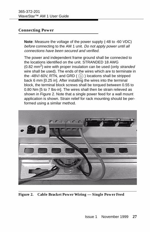
The power and independent frame ground shall be connected to the locations identified on the unit. STRANDED 18 AWG (0.82 mm2) wire with proper insulation can be used (only stranded wire shall be used). The ends of the wires which are to terminate in the -48V/-60V, RTN, and GRD ( ) locations shall be stripped back 6 mm [0.25 in]. After installing the wires into the terminal block, the terminal block screws shall be torqued between 0.55 to 0.80 Nm [5 to 7 lbs-in]. The wires shall then be strain relieved as shown in Figure 2. Note that a single power feed for a wall mount application is shown. Strain relief for rack mounting should be per-formed using a similar method.
Figure 2. Cable Bracket Power Wiring — Single Power Feed
28 Issue 1 November 1999
365-372-201WaveStar™ AM 1 User Guide
Grounding Option
When it is required to interconnect earth ground ( ) to RTN, a jumper wire can be added externally between positions 5 and 6 (the bottom two positions) of the terminal block (see Figure 2). The jumper shall be 18 AWG (0.82 mm2) stranded wire. A 25 mm [1 in long] wire shall be used, the ends stripped 6 mm [0.25 in]. Bend the jumper into a “U” shape and install in positions 5 and 6 of the termi-nal block with a screw torque of 0.55 to 0.80 Nm [5 to 7 lbs-in].
Powering from AC/DC Converters
When powering the WaveStar™ AM 1 with the optional AC-to-DC converter, you must connect a jumper wire between the RTN COM and the earth ground ( ). Failure to do so may allow the -48V input to float and affect the operation of the unit. See the GROUND-ING OPTION above.
Powering from DC/DC Converters
When powering the WaveStar™ AM 1 with the optional DC-to-DC converter, you must connect a jumper wire between the RTN COM and the earth ground ( ). Failure to do so may allow the -48V input to float and affect the operation of the unit. See the GROUND-ING OPTION above. NOTE: The optional DC-to-DC converter must be powered by a Safety Extra Low Voltage (SELV) -48V dc Source.
Connecting STM-1 Fibers
The routing of the fibers away from the WaveStar™ AM 1 should be in accordance with the specifications for the selected fiber. Care should be taken not to exceed the bending radius when placing the fiber (nominal minimum 10cm bending radius). Exceeding the rec-ommended radius may cause distortion and poor signal quality. Cables should be strain relieved to prevent any force from being exerted on the connectors.
Clean all connections, as required, before attaching.

Issue 1 November 1999 29
365-372-201WaveStar™ AM 1 User Guide
Connecting E1 Tributaries
The routing of the E1 tributaries should be in accordance with the recommended practices of the cable selected. Cables should be strain relieved to prevent any force from being exerted on the con-nectors.
Connecting E3 Tributaries (optional)
The routing of the E3 tributaries should be in accordance with the recommended practices of the cable selected. Cables should be strain relieved to prevent any force from being exerted on the con-nectors.
MDI/MDO Connections
Prepare the MDI/MDO (Miscellaneous Discreet Input / Miscella-neous Discreet Output) connections by stripping the wires back 5 mm [0.2 in]. Install the wires and then torque the MDI/MDO terminal block screws to 0.2 Nm (1.7 lb-in).
Wire size range:
Nominal 0.5 mm2
Solid 0.03 to 1.00 mm2 (17 AWG)
Stranded 0.03 to 0.75 mm2 (18 AWG)
30 Issue 1 November 1999
365-372-201WaveStar™ AM 1 User Guide
Synchronization and Timing
The WaveStar™ AM 1 complies with the synchronization require-ments as specified in ITU-T Recommendation G.813, option 1.
Synchronization
A synchronization reference for the WaveStar™ AM 1 can be extracted from one of the following sources:
Either one of the STM-1 line inputs
One of the 2 Mbit/s data inputs.
Note: When used as a timing reference, the 2 Mbit/s data input must comply with the wander tolerance, jitter tolerance, and fre-quency offset (< 4.6 ppm) requirements specified in ITU-T Recom-mendation G.813, option 1.
SYNC-OUT
The external synchronization port (SYNC-OUT) can be locked to the input signal selected for synchronization or to the internal clock. SYNC-OUT provides 2048 kHz according to ITU-T G.703.
Terminal Configuration
When connecting two WaveStar™ AM 1s directly together (optically back-to-back, not through an SDH network) in a 1+1 MSP terminal configuration, the following recommendations should be followed in order to ensure proper synchronization:
a. Using ITM-CIT software, provision one of the AM 1s as locked to either reference: one of the 155.52 Mbit/s STM-1 inputs or one of the 2.048 Mbit/s inputs.
b. If the first AM 1 is locked to one of the 155.52 Mbit/s STM-1 inputs, provision the second AM 1 as free-running.
Issue 1 November 1999 31
365-372-201WaveStar™ AM 1 User Guide
c. If the first AM 1 is locked to one of the 2.048 Mbit/s inputs, provision the second AM 1 as locked to the 155.52 Mbit/s input.
Timing Modes
Timing of the WaveStar™ AM 1 can be referenced to either one of the two 155.52 Mbit/s optical STM-1 input lines, or any one of the 2.048 Mbit/s E1 input tributaries. The WaveStar™ AM 1 provides one external reference clock output (SYNC-OUT) at 2.048 Mhz.
The WaveStar™ AM 1 can operate in the following modes:
Locked: Referenced to a suitable input signal such as one of the STM-1 inputs or one of the 2 Mbit/s data inputs. (Note that the timing circuitry will not accept a reference input from an external office station clock input.)
Hold-Over: Operates from the stored frequency data of the last available input reference.
Free Running: The internal time-base oscillator is selected (± 4.6 ppm).
32 Issue 1 November 1999
365-372-201WaveStar™ AM 1 User Guide
Transmission Protection
SNC/N Protection
General VC-12/VC-3 SNC/N protection (non-revertive):
In an add/drop ring configuration, the system allows the set up of a non-intrusively monitored subnetwork connection protection scheme between any incoming TU-12 or TU-3 from the east line interface, and any TU-12 or TU-3 from the west line interface. A protection switch will occur based on “path signal fail,” TIM, UNEQ, or DEG conditions. The threshold is user-settable for DEG. Only non-revertive operation is possible and manual and forced switch-ing commands are supported.
1+1 MSP Protection
1+1 MSP protection in terminal applications:
In terminal applications between two WaveStar™ AM 1s, a 1+1 MSP protection relation can be set up by the user. Switching can either be revertive or non-revertive, uni-directional or bi-directional.
Issue 1 November 1999 33
365-372-201WaveStar™ AM 1 User Guide
Operations
Note: The following information describes the WaveStar™ AM 1’s operations features. To implement these features refer to SECTION II of this guide. SECTION II provides information and instructions on provisioning the equipment, transmission, protection and timing using the PC-based ITM-CIT software.
Operations include the following:
Operations Interfaces
Maintenance supervision
System alarm indicators
Software maintenance
Maintenance testing
Performance monitoring
Self-diagnostics and recovery
4 MDI, 4 MDO contacts
Operations Interfaces and Administration
The WaveStar™ AM 1 has been configured for remote and local operations management via the Lucent Technologies’ Integrated Management Network (ITM) management systems. Remote man-agement can be via the STM-1 DCC and the ITM-SC software (ITM-SC can also be connected locally). Local and remote (remote to other NEs in the same network only) communications are via ITM-CIT. Local connections are via an RJ45 connector mounted on the WaveStar™ AM 1 unit and the PC-based ITM-CIT software.
Management access features include:
Simultaneous access by the ITM-SC and local workstations
34 Issue 1 November 1999
365-372-201WaveStar™ AM 1 User Guide
Remote access to other NEs in the same network via ITM-CIT
Network element level security via three password controlled authorization levels: ADMIN, CONFIGURE, and VIEW.
Maintenance Supervision
Transmission and equipment fault supervision is monitored remotely and/or locally via the ITM-SC, and locally via LEDs on the unit and via ITM-CIT. The local ITM-CIT may also be used to remotely access other NEs in the network.
Alarm and port termination monitoring features include:
Physical port provisioning of STM-1, E1, and E3 in three dif-ferent modes: automatic (AUTO), monitored (MON), or non-monitored (NMON).
VC path termination point provisioning in either the MON or NMON mode
Alarm severity levels of PROMPT, DEFERRED, and INFOR-MATION provisionable for each alarm type
User can assign an alarm message and severity to each MDI (Miscellaneous Discrete Input).
Failure reporting features:
Alarm messages are reported via ITM-CIT and ITM-SC. These messages identify failures and provide information useful for correcting faults and clearing alarms.
Alarm forwarding to the remote management system is sup-ported via ITM-SC (LAN-10baseT) and to the local worksta-tion via the F-interface (ITM-CIT).
The NE can store the 500 most recent alarm events and can be accessed by either the local or remote monitoring sta-tions.
Failures are reported as defined in G.783 and ETS 300417.
Issue 1 November 1999 35
365-372-201WaveStar™ AM 1 User Guide
System Alarm Indicators
The WaveStar™ AM 1 supports two LEDs which provide the following maintenance information:
1 Green LED to indicate power
1 Red LED to indicate unit fault or signal failure
(See the following TROUBLESHOOTING section)
Software Maintenance
Software maintenance includes the following:
Non-service affecting software download via ITM-SC (remotely) and ITM-CIT (locally)
Database upload/download from the ITM-SC
In-service database reprovisioning available via the local workstation running ITM-CIT
Maintenance Testing
E1 loopbacks are available for circuit testing during maintenance operations
36 Issue 1 November 1999
365-372-201WaveStar™ AM 1 User Guide
Performance Monitoring
Provisioning and retrieval of performance monitoring parameters are derived from the overhead bytes (SOH, POH of each VC) and are in accordance with ITU-T Recommendations G.874 and G.826. This is accomplished via ITM-SC and ITM-CIT. Performance thresholds counts are user settable.
The following four parameters are available to estimate the error performance of a path: SES, ES, BBE, and UAS
SES: number of Severely Errored Seconds in the received signal
ES: number of Errored Seconds in the received signal
BBE: number of Background Block Errors in the received signal
UAS: number of UnAvailable Seconds in the received signal.
Monitoring can be done on the incoming STM-1 optical inter-faces of the WaveStar™ AM 1 unit
Monitoring can be done on any incoming VC-4, VC-3 or VC-12 terminating in the unit
Performance monitoring data is stored in one current and sixteen recent 15 minute registers, and one current and one recent 24 hour registers
Threshold reports are generated when user-settable perfor-mance parameters are exceeded during 15 minute and 24 hour periods
Issue 1 November 1999 37
365-372-201WaveStar™ AM 1 User Guide
Self-Diagnostics and Recovery
The WaveStar™ AM 1 supports the following diagnostics and recovery features:
The WaveStar™ AM 1 continuously runs self-diagnostic tests to monitor the health of the transmission system
The WaveStar™ AM 1 auto-recovers after a power failure
The WaveStar™ AM 1 will auto-recover from a database fail-ure by requesting the backup database be downloaded from the ITM-SC.
Miscellaneous Discrete Inputs & Outputs
The WaveStar™ AM 1 provides four miscellaneous discrete inputs (MDIs) that can be used to read external devices assigned by the customer. Examples are monitoring temperature, humidity, open doors, etc.
The WaveStar™ AM 1 provides four miscellaneous discrete outputs (MDOs) that can be used to drive external devices assigned by the customer. Examples are signaling devices, temperature conditioning, etc.
Note that MDO#1 has been assigned to indicate a power failure (normally open contacts will close), MDO#2-4 are unassigned.
38 Issue 1 November 1999
365-372-201WaveStar™ AM 1 User Guide
LEDs Normal Operation
The WaveStar™ AM 1 is equipped with two LEDs indicating the fol-lowing conditions:
When no LEDs are lit it is an indiction that there is no power.
When the green LED (POWER) is ON it indicates the unit is receiving power
When both LEDs are ON it indicates that the unit is receiving power and there may be a problem with the unit (see Trou-bleshooting).
When the FAULT LED is FLASHING it indicates a problem with the incoming signal (see Troubleshooting).
Software Upgrades
Software upgrades may be executed remotely via the DCC using ITM-SC software. They may also be done locally via the PC-based ITM-CIT.
New software releases will be downloaded into a separate storage area of the WaveStar™ AM 1. Then, at the customers designated time, this new software will be activated as the “working” software and the unit will remain “in-service” with no disruption to traffic. However, all communication with the AM 1 will be suspended during this activation process.
Issue 1 November 1999 39
365-372-201WaveStar™ AM 1 User Guide
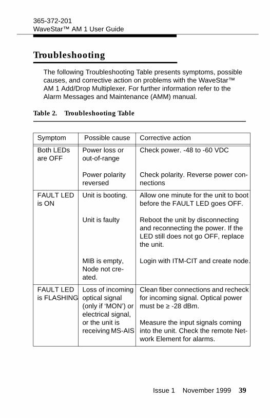
Troubleshooting
The following Troubleshooting Table presents symptoms, possible causes, and corrective action on problems with the WaveStar™ AM 1 Add/Drop Multiplexer. For further information refer to the Alarm Messages and Maintenance (AMM) manual.
Table 2. Troubleshooting Table
Symptom Possible cause Corrective action
Both LEDs are OFF
Power loss or out-of-range
Power polarity reversed
Check power. -48 to -60 VDC
Check polarity. Reverse power con-nections
FAULT LED is ON
Unit is booting.
Unit is faulty
MIB is empty, Node not cre-ated.
Allow one minute for the unit to boot before the FAULT LED goes OFF.
Reboot the unit by disconnecting and reconnecting the power. If the LED still does not go OFF, replace the unit.
Login with ITM-CIT and create node.
FAULT LED is FLASHING
Loss of incoming optical signal (only if ‘MON’) or electrical signal, or the unit is receiving MS-AIS
Clean fiber connections and recheck for incoming signal. Optical power must be ≥ -28 dBm.
Measure the input signals coming into the unit. Check the remote Net-work Element for alarms.
40 Issue 1 November 1999
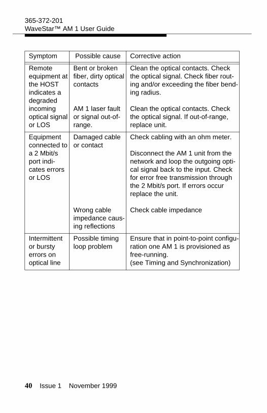
365-372-201WaveStar™ AM 1 User Guide
Remote equipment at the HOST indicates a degraded incoming optical signal or LOS
Bent or broken fiber, dirty optical contacts
AM 1 laser fault or signal out-of-range.
Clean the optical contacts. Check the optical signal. Check fiber rout-ing and/or exceeding the fiber bend-ing radius.
Clean the optical contacts. Check the optical signal. If out-of-range, replace unit.
Equipment connected to a 2 Mbit/s port indi-cates errors or LOS
Damaged cable or contact
Wrong cable impedance caus-ing reflections
Check cabling with an ohm meter.
Disconnect the AM 1 unit from the network and loop the outgoing opti-cal signal back to the input. Check for error free transmission through the 2 Mbit/s port. If errors occur replace the unit.
Check cable impedance
Intermittent or bursty errors on optical line
Possible timing loop problem
Ensure that in point-to-point configu-ration one AM 1 is provisioned as free-running.(see Timing and Synchronization)
Symptom Possible cause Corrective action

Issue 1 November 1999 41
365-372-201WaveStar™ AM 1 User Guide
Connector and Fiber Cleaning
Clean connectors by blowing any lint or dust from inside the con-nectors using compressed air held at least 8 cm (3 inches) away.
Clean optical fiber-end face and sides of connector with lint-free, optical quality tissue moistened with isopropyl alcohol. Carefully wipe fiber-end face and sides again with clean, dry, lint-free optical quality tissue.
Power Supply
The WaveStar™ AM 1 must be supplied with an input voltage of -48 or -60 VDC. Power consumption is less than 25 watts with the basic unit, less than 50 watts with either option card.
42 Issue 1 November 1999
365-372-201WaveStar™ AM 1 User Guide
Product Support
Technical Assistance
Many of our customers have established their own technical sup-port procedures. These procedures usually involve escalation within their own companies. However, some issues may require additional assistance from Lucent Technologies.
Lucent Technologies has been and continues to be committed to providing excellence in technical customer support for its products and services. Therefore, we provide a hierarchical support structure ready and available to solve any WaveStar™ AM 1 technical issue.
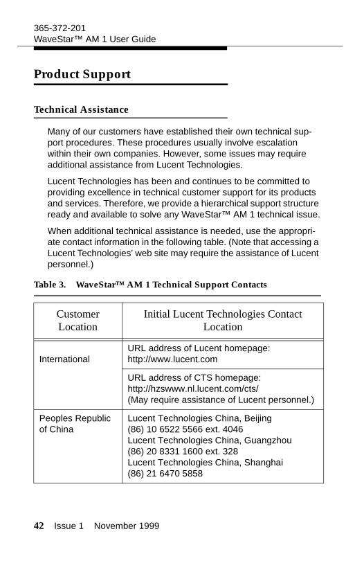
When additional technical assistance is needed, use the appropri-ate contact information in the following table. (Note that accessing a Lucent Technologies’ web site may require the assistance of Lucent personnel.)
Table 3. WaveStar™ AM 1 Technical Support Contacts
Customer Location
Initial Lucent Technologies Contact Location
International URL address of Lucent homepage:http://www.lucent.com
URL address of CTS homepage:http://hzswww.nl.lucent.com/cts/(May require assistance of Lucent personnel.)
Peoples Republic of China
Lucent Technologies China, Beijing(86) 10 6522 5566 ext. 4046Lucent Technologies China, Guangzhou(86) 20 8331 1600 ext. 328Lucent Technologies China, Shanghai(86) 21 6470 5858
Issue 1 November 1999 43
365-372-201WaveStar™ AM 1 User Guide
Warranty
Warranty, support, and trouble escalation procedures have been established on a per country basis. Contact your Lucent Technolo-gies account representative for details.
Discontinued Availability
Lucent Technologies reserves the right to notify the customer in advance of the intention to Discontinue the Availability (DA) of a product. Lucent Technologies also reserves the right to offer a Technical Support Contract (TSC) to make repair and technical support services available for an additional period of time after a product has been discontinued. All TSC services will be at a speci-fied price dependent on the terms and conditions of the contract.
The rights and obligations of Lucent Technologies and the customer shall neither be assigned nor delegated without prior written con-sent of the other party, except that Lucent Technologies may assign its obligations to any of its affiliates or non-Lucent Technologies contractors without further consent by the customer.
Standard Repair
If Lucent Technologies determines that a product is not defective or is in conformance, the customer shall pay Lucent Technologies the costs of handling, inspecting, testing, and transporting the product and, if applicable, travel and related expenses.
Repair Interval
Lucent Technologies repair locations set their own standards for return intervals. On average, the minimum time to return repairs to the customer is 14 days from the receipt of the product by the repair location. The maximum time to return repairs to the customer can range from 50 to 180 days.

44 Issue 1 November 1999
365-372-201WaveStar™ AM 1 User Guide
Out-Of-Warranty Provisions
For any activity associated with repair or replacement of hardware and/or software systems that is determined by Lucent Technologies to be out of warranty, materials an labor will be billed at Lucent Technologies list price (time-and-materials plus additional incurred expenses), or in accordance with a separate Technical Support Contract.
International Repair and Service
The customer or the customer’s in-country representative should send a description of the material to be returned for repair or ser-vice including the quantity, comcodes, and serial numbers (if avail-able) to the Lucent Technologies’ Charlotte Service Center.
After the Charlotte Service Center receives the repair information, they will assign an order number and fax an Authorization To Repair Form to the customer or the customer’s in-country representative.
The material can then be consigned and shipped to:
Lucent Technologies
Charlotte Service Center
6701-A Northpark Blvd.
Charlotte, NC 28216 USA
Attn: International Repair
Notify: Hipage Co. (704) 357-3050
After the material has been shipped, the following information should be faxed to the Charlotte Service Center:
Customer’s return address
Customer contact name, telephone number, and fax number
Value of material
Issue 1 November 1999 45
365-372-201WaveStar™ AM 1 User Guide
Identification of any hazardous equipment or material
Shipping information including the date of shipment, air way-bill, carrier name, flight number, number of cartons, and weight of material
When the material arrives at the Charlotte Service Center, it is entered into the Repair, Service, and Return database for tracking purposes, to verify shipment and quantities, and to determine the appropriate repair location. The material is then shipped to the appropriate repair location.
The repair locations will repair the material and then ship it back to the Charlotte Service Center. If it is determined that an item is not repairable and the item is under factory warranty, a replacement will be sent. If the item is out of factory warranty, the customer will advise their Country Desk Representative if they would like to order a replacement.
The Charlotte Service Center will prepare the paperwork for exporting the material, and ship the material to the customer. When available, the Charlotte Service Center will fax the shipping information to the customer or the customer’s in-country representative.
Upon receipt of the material, the customer or the customer’s in-country representative should send the Charlotte Service Center the order numbers of the material received and the date the material was received. The Charlotte Service Center will then close the order on the Repair, Service, and Return database.

46 Issue 1 November 1999
365-372-201WaveStar™ AM 1 User Guide
Issue 1 November 1999 47
SECTION II
This section contains information and instructions on provisioning the equipment, transmission, protection and timing of the Wave-Star™ AM 1 using ITM-CIT software. It is assumed that the user of this guide is conversant with the use of ITM-CIT and the WaveStar™ AM 1.
Equipment Provisioning
Intended use
This subsection provides all procedures needed to provision the equipment of a WaveStar™ AM 1 network element when using the ITM-CIT.
Isolated State
Arriving from the factory, the WaveStar™ AM 1 is in the "isolated state." No DCC communication is possible and it is not possible to get an association with the ITM-SC as long as the network element is in the isolated state. To enable an association with the ITM-SC this isolated state must be removed. The isolated state is removed if the Area ID is changed from 0000 to any other value.
Creating a Node
Purpose
Creating a node provides the basic information necessary to place an NE into service.
48 Issue 1 November 1999
365-372-201WaveStar™ AM 1 User Guide
Prerequisites
Before starting to create a node make certain:
the name, address, and location of the node are known.
the type of units physically present in the NE are known.
Precaution
For the WaveStar™ AM 1, the only slot which may be assigned by the user is TS2.
Any mistake in provisioning the slots will result in a failure when attempting to create the node. When a mistake has been made, after clicking Finish, the error message “Slot configuration con-flict” appears. The node creation has failed, and the entire node creation process must be begun anew.
Windows for Creating a Node
Windows to Use
The following windows are used in creating a node.
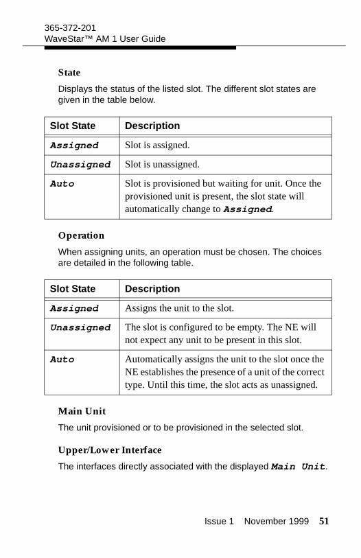
Node Creation
Node Creation - Provisioned Slots Node Details
Node Details
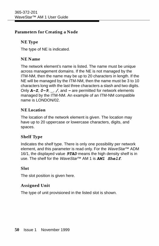
The Node Creation - Parameters window is used in creating a node. It allows entry of the basic node details.
The Node Creation - Provisioned Slots window is to provision units in a node that is being created.
Issue 1 November 1999 49
365-372-201WaveStar™ AM 1 User Guide
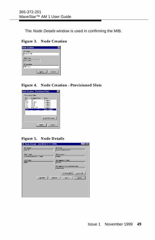
The Node Details window is used in confirming the MIB.
Figure 3. Node Creation
Figure 4. Node Creation - Provisioned Slots
Figure 5. Node Details
50 Issue 1 November 1999
365-372-201WaveStar™ AM 1 User Guide
Parameters for Creating a Node
NE Type
The type of NE is indicated.
NE Name
The network element’s name is listed. The name must be unique across management domains. If the NE is not managed by the ITM-NM, then the name may be up to 20 characters in length. If the NE will be managed by the ITM-NM, then the name must be 3 to 10 characters long with the last three characters a slash and two digits. Only A-Z, 0-9, _, /, and - are permitted for network elements managed by the ITM-NM. An example of an ITM-NM compatible name is LONDON/02.
NE Location
The location of the network element is given. The location may have up to 20 uppercase or lowercase characters, digits, and spaces.
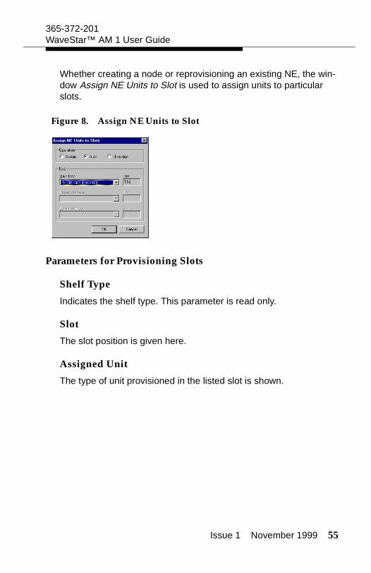
Shelf Type
Indicates the shelf type. There is only one possibility per network element, and this parameter is read only. For the WaveStar™ ADM 16/1, the displayed value 9TAD means the high density shelf is in use. The shelf for the WaveStar™ AM 1 is AM1 Shelf.
Slot
The slot position is given here.
Assigned Unit
The type of unit provisioned in the listed slot is shown.
Issue 1 November 1999 51
365-372-201WaveStar™ AM 1 User Guide
State
Displays the status of the listed slot. The different slot states are given in the table below.
Operation
When assigning units, an operation must be chosen. The choices are detailed in the following table.
Main Unit
The unit provisioned or to be provisioned in the selected slot.
Upper/Lower Interface
The interfaces directly associated with the displayed Main Unit.
Slot State Description
Assigned Slot is assigned.
Unassigned Slot is unassigned.
Auto Slot is provisioned but waiting for unit. Once the provisioned unit is present, the slot state will automatically change to Assigned.
Slot State Description
Assigned Assigns the unit to the slot.
Unassigned The slot is configured to be empty. The NE will not expect any unit to be present in this slot.
Auto Automatically assigns the unit to the slot once the NE establishes the presence of a unit of the correct type. Until this time, the slot acts as unassigned.
52 Issue 1 November 1999
365-372-201WaveStar™ AM 1 User Guide
Create a Node
Procedure
Follow these steps to create a network element.
1. Select Management -> Node Creation - Param-eters.
Result: The Node Creation - Parameters window appears.
2. Enter the NE Name and NE Location.
Result: The network element name and location appear, respectively, in the fields NE Name and NE Location.
3. Using the pull-down menu select the correct NE Type.
4. Click Next.
Result: The window Node Creation - Provisioned Slots appears.
5. Complete the procedure “Provision Slots.”
Important! For the WaveStar™ AM 1, the only slot which may be user assigned is TS2.
Result: The slots of the NE are properly assigned.
6. Complete the procedure “Confirm the MIB”.
Result: The MIB is now confirmed, and after reestablishing the connection between the NE and the ITM-CIT, the MIB status in the window Node Details should be Filled.
Issue 1 November 1999 53
365-372-201WaveStar™ AM 1 User Guide
7. When an association with the ITM-SC must be made make sure the network element is not in the isolated state (this is the state it is in arriving from the factory). Select Manage-ment -> Overlay Comms Network -> DCN to view if the network element is in the isolated state. If the net-work element is in the isolated state, this can be changed by setting the area address from 0000 to any other value.
Provisioning Slots
Purpose
Use this procedure to provision the slots of a network element.
Prerequisites
Before provisioning the network element slot configuration it is assumed that the new configuration of the NE is known. This includes the exact types of units to be provisioned and the corre-sponding slot positions for these units.
Precautions
For the WaveStar™ AM 1, the only slot which may be user assigned is TS2.
An assigned unit may be changed without changing the slot state. In other words, it is possible to change the unit while maintaining the status “Assigned” or “Auto.”
Windows for Provisioning Slots
Windows to Use
The following windows are used in viewing slot configurations:
Node Creation - Provision Slots
54 Issue 1 November 1999
365-372-201WaveStar™ AM 1 User Guide
Provisioned NE Components
Assign NE Units to Slot
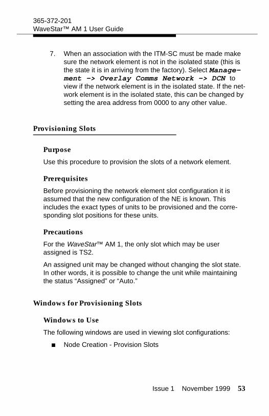
When initially provisioning the node, the Node Creation - Provision Slots window is used in provisioning the slots.
Figure 6. Node Creation - Provisioned Slots
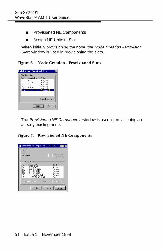
The Provisioned NE Components window is used in provisioning an already existing node.
Figure 7. Provisioned NE Components
Issue 1 November 1999 55
365-372-201WaveStar™ AM 1 User Guide
Whether creating a node or reprovisioning an existing NE, the win-dow Assign NE Units to Slot is used to assign units to particular slots.
Figure 8. Assign NE Units to Slot
Parameters for Provisioning Slots
Shelf Type
Indicates the shelf type. This parameter is read only.
Slot
The slot position is given here.
Assigned Unit
The type of unit provisioned in the listed slot is shown.
56 Issue 1 November 1999
365-372-201WaveStar™ AM 1 User Guide
State
Displays the status of the listed slot. The different slot states are given in the table below.
Operation
When assigning units, an operation must be chosen. The choices are detailed in the following table.
Main Unit
The unit provisioned or to be provisioned in the selected slot.
Slot State Description
Assigned Slot is assigned.
Unassigned Slot is unassigned.
Auto Slot is provisioned but waiting for unit. Once the provisioned unit is present, the slot state will automatically change to Assigned.
Slot State Description
Assigned Assigns the unit to the slot.
Unassigned The slot is configured to be empty. The NE will not expect any unit to be present in this slot.
Auto Automatically assigns the unit to the slot once the NE establishes the presence of a unit of the correct type. Until this time, the slot acts as unassigned.
Issue 1 November 1999 57
365-372-201WaveStar™ AM 1 User Guide
Upper/Lower Interface
The interfaces directly associated with the displayed Main Unit.
Provision Slots
Procedure
Follow these steps to provision the slots of an NE. This includes both assigning and unassigning units.
Important! For the WaveStar™ AM 1, the only slot which may be user assigned is TS2.
1. If provisioning units during node creation, then go to step 2.For existing NEs, select Provisioning -> Equip-ment -> Provisioned NE Components.
Result: The Provisioned NE Components window appears.
2. Select the slot TS2 from the list in the window, and click Assign/Unassign.
Result: The Assign NE Units to Slot window appears with information concerning the selected slot and its associated slots.
3. Select the desired operation from the selections at the top of the window.
Result: The correct operation is selected.
4. If assigning units, use the pull-down menu for Main Unit and select the correct unit corresponding to the displayed slot.
Result: The correct unit appears as the new Main Unit.
58 Issue 1 November 1999
365-372-201WaveStar™ AM 1 User Guide
5. Click OK.
Result: The desired operation for this slot is performed, and the window Provisioned NE Components again appears.
Important! When assigning units during node creation, instead of the Provisioned NE Components window, the window Node Creation - Provision Slots will reappear.
6. If creating a node, then click Finish. Otherwise, click Close.
Result: The window Provisioned NE Components (or in the case of node creation, Node Creation - Provision Slots) disappears.
Confirming the MIB
Purpose
To make any provisioning changes a part of the Management Infor-mation Base (MIB).
Precautions
Performing an MIB confirm will cause the NE to reset. A new login, after waiting several minutes for the reset to take place, will have to be performed.
Confirming the MIB for an existing NE can result in traffic disrup-tions.
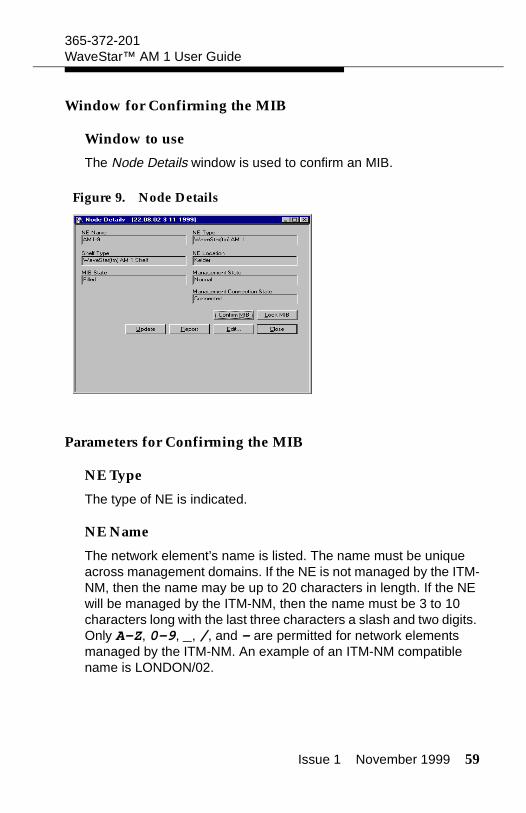
Issue 1 November 1999 59
365-372-201WaveStar™ AM 1 User Guide
Window for Confirming the MIB
Window to use
The Node Details window is used to confirm an MIB.
Figure 9. Node Details
Parameters for Confirming the MIB
NE Type
The type of NE is indicated.
NE Name
The network element’s name is listed. The name must be unique across management domains. If the NE is not managed by the ITM-NM, then the name may be up to 20 characters in length. If the NE will be managed by the ITM-NM, then the name must be 3 to 10 characters long with the last three characters a slash and two digits. Only A-Z, 0-9, _, /, and - are permitted for network elements managed by the ITM-NM. An example of an ITM-NM compatible name is LONDON/02.
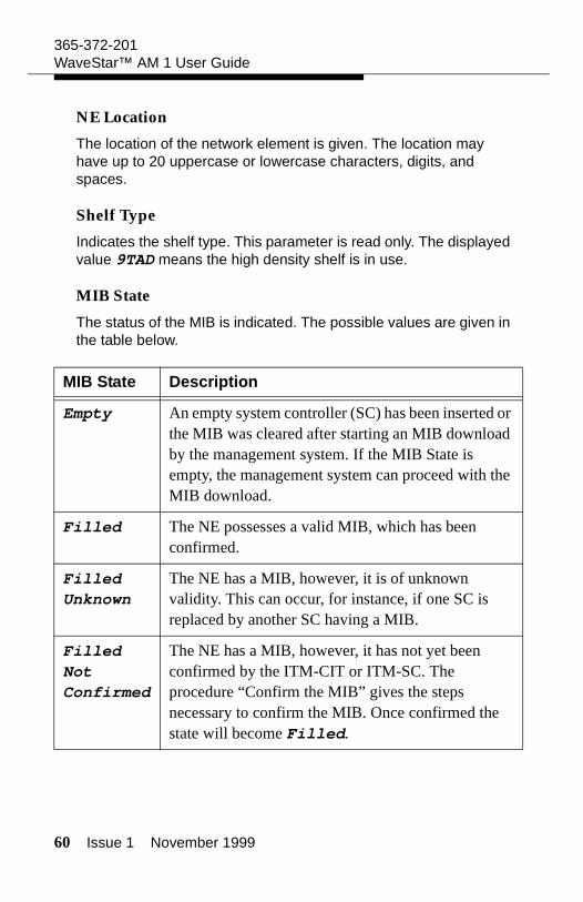
60 Issue 1 November 1999
365-372-201WaveStar™ AM 1 User Guide
NE Location
The location of the network element is given. The location may have up to 20 uppercase or lowercase characters, digits, and spaces.
Shelf Type
Indicates the shelf type. This parameter is read only. The displayed value 9TAD means the high density shelf is in use.
MIB State
The status of the MIB is indicated. The possible values are given in the table below.
MIB State Description
Empty An empty system controller (SC) has been inserted or the MIB was cleared after starting an MIB download by the management system. If the MIB State is empty, the management system can proceed with the MIB download.
Filled The NE possesses a valid MIB, which has been confirmed.
Filled Unknown
The NE has a MIB, however, it is of unknown validity. This can occur, for instance, if one SC is replaced by another SC having a MIB.
Filled Not Confirmed
The NE has a MIB, however, it has not yet been confirmed by the ITM-CIT or ITM-SC. The procedure “Confirm the MIB” gives the steps necessary to confirm the MIB. Once confirmed the state will become Filled.
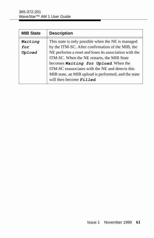
Issue 1 November 1999 61
365-372-201WaveStar™ AM 1 User Guide
Waiting for Upload
This state is only possible when the NE is managed by the ITM-SC. After confirmation of the MIB, the NE performs a reset and loses its association with the ITM-SC. When the NE restarts, the MIB State becomes Waiting for Upload. When the ITM-SC reassociates with the NE and detects this MIB state, an MIB upload is performed, and the state will then become Filled.
MIB State Description
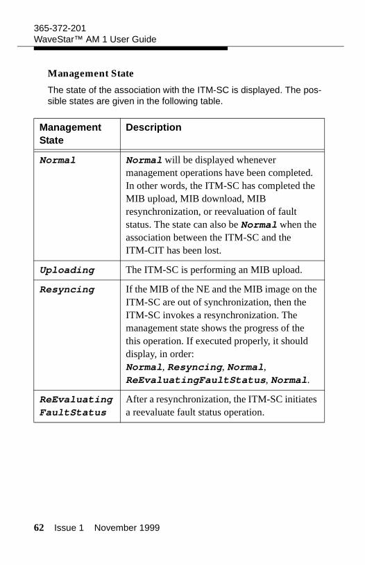
62 Issue 1 November 1999
365-372-201WaveStar™ AM 1 User Guide
Management State
The state of the association with the ITM-SC is displayed. The pos-sible states are given in the following table.
Management State
Description
Normal Normal will be displayed whenever management operations have been completed. In other words, the ITM-SC has completed the MIB upload, MIB download, MIB resynchronization, or reevaluation of fault status. The state can also be Normal when the association between the ITM-SC and the ITM-CIT has been lost.
Uploading The ITM-SC is performing an MIB upload.
Resyncing If the MIB of the NE and the MIB image on the ITM-SC are out of synchronization, then the ITM-SC invokes a resynchronization. The management state shows the progress of the this operation. If executed properly, it should display, in order: Normal, Resyncing, Normal, ReEvaluatingFaultStatus, Normal.
ReEvaluating FaultStatus
After a resynchronization, the ITM-SC initiates a reevaluate fault status operation.
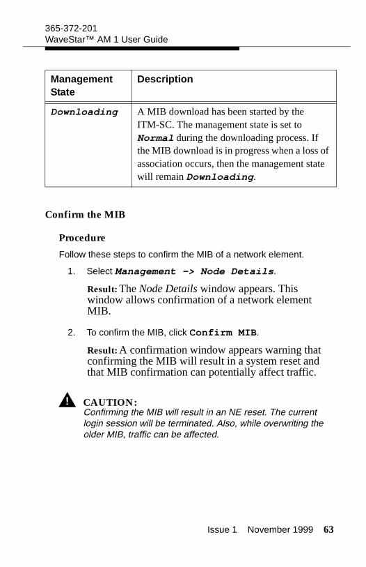
Issue 1 November 1999 63
365-372-201WaveStar™ AM 1 User Guide
Confirm the MIB
Procedure
Follow these steps to confirm the MIB of a network element.
1. Select Management -> Node Details.
Result: The Node Details window appears. This window allows confirmation of a network element MIB.
2. To confirm the MIB, click Confirm MIB.
Result: A confirmation window appears warning that confirming the MIB will result in a system reset and that MIB confirmation can potentially affect traffic.
! CAUTION:Confirming the MIB will result in an NE reset. The current login session will be terminated. Also, while overwriting the older MIB, traffic can be affected.
Downloading A MIB download has been started by the ITM-SC. The management state is set to Normal during the downloading process. If the MIB download is in progress when a loss of association occurs, then the management state will remain Downloading.
Management State
Description
64 Issue 1 November 1999
365-372-201WaveStar™ AM 1 User Guide
3. Click Yes.
Result: The operation will be started. Confirming the MIB should take several minutes. During this time, the connection between the ITM-CIT and the NE will be lost. To reestablish this connection, a login must once again be performed after waiting for the operation to complete.
4. Login again.
5. Select Management -> Node Details.
Result: The Node Details window appears. In this window, the MIB state can be viewed. It should now be Filled.
6. Click Close.
Result: The Node Details window disappears.
Viewing NE Slot Information
Purpose
Use this procedure to view how the slots of a provisioned network element are configured.
Windows for Viewing NE Slot Information
Windows to UseWindows to Use
The following windows are used in viewing slot configurations:
Provisioned NE Components
Provisioned NE Slot Information
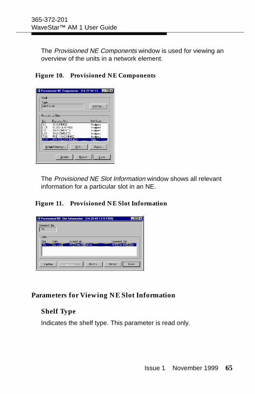
Issue 1 November 1999 65
365-372-201WaveStar™ AM 1 User Guide
The Provisioned NE Components window is used for viewing an overview of the units in a network element.
Figure 10. Provisioned NE Components
The Provisioned NE Slot Information window shows all relevant information for a particular slot in an NE.
Figure 11. Provisioned NE Slot Information
Parameters for Viewing NE Slot Information
Shelf Type
Indicates the shelf type. This parameter is read only.
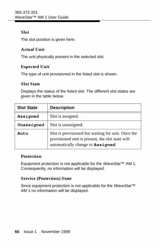
66 Issue 1 November 1999
365-372-201WaveStar™ AM 1 User Guide
Slot
The slot position is given here.
Actual Unit
The unit physically present in the selected slot.
Expected Unit
The type of unit provisioned in the listed slot is shown.
Slot State
Displays the status of the listed slot. The different slot states are given in the table below.
Protection
Equipment protection is not applicable for the WaveStar™ AM 1. Consequently, no information will be displayed.
Service (Protection) State
Since equipment protection is not applicable for the WaveStar™ AM 1 no information will be displayed.
Slot State Description
Assigned Slot is assigned.
Unassigned Slot is unassigned.
Auto Slot is provisioned but waiting for unit. Once the provisioned unit is present, the slot state will automatically change to Assigned.
Issue 1 November 1999 67
365-372-201WaveStar™ AM 1 User Guide
Operation
When assigning units, an operation must be chosen. The choices are detailed in the following table.
Selected Slot
Indicates the slot selected.
Protection Function
This field is greyed out for the WaveStar™ AM 1.
Function
Describes if the unit is the main unit or the upper or lower interface associated with this main unit.
View NE Slot Information
Procedure
Follow these steps to view the configuration of slots in a provi-sioned network element.
Slot State Description
Assigned Assigns the unit to the slot.
Unassigned The slot is configured to be empty. The NE will not expect any unit to be present in this slot.
Auto Automatically assigns the unit to the slot once the NE establishes the presence of a unit of the correct type. Until this time, the slot acts as unassigned.
68 Issue 1 November 1999
365-372-201WaveStar™ AM 1 User Guide
1. Select Provisioning -> Equipment -> Provi-sioned NE Components.
Result: The Provisioned NE Components window appears.
2. Select a slot from the list Provisioned Slots.
3. Click Details.
Result: The Provisioned NE Slot Information window appears with the information for the selected slot.
4. Click Close.
Result: The Provisioned NE Slot Information window disappears.
5. Click Close.
Result: The Provisioned NE Components window disappears.
Viewing Hardware Inventory
Purpose
Viewing the hardware inventory allows the user to see all provi-sioned NE components, along with all of the units’ relevant numeric codes.
Windows for Viewing Hardware Inventory
Windows to Use
The following windows are used in viewing hardware inventory for the shelf or the slots.
Provisioned NE Components
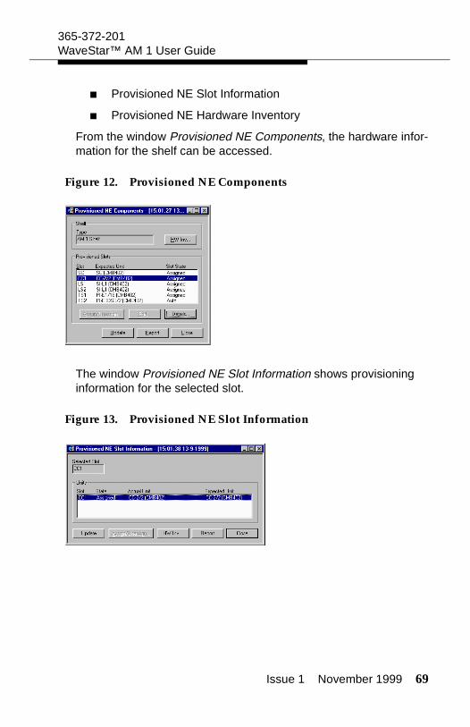
Issue 1 November 1999 69
365-372-201WaveStar™ AM 1 User Guide
Provisioned NE Slot Information
Provisioned NE Hardware Inventory
From the window Provisioned NE Components, the hardware infor-mation for the shelf can be accessed.
Figure 12. Provisioned NE Components
The window Provisioned NE Slot Information shows provisioning information for the selected slot.
Figure 13. Provisioned NE Slot Information
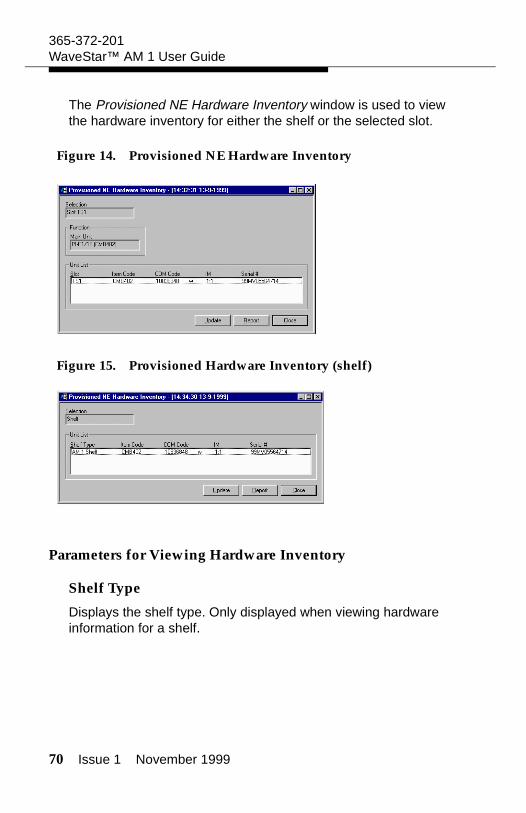
70 Issue 1 November 1999
365-372-201WaveStar™ AM 1 User Guide
The Provisioned NE Hardware Inventory window is used to view the hardware inventory for either the shelf or the selected slot.
Figure 14. Provisioned NE Hardware Inventory
Figure 15. Provisioned Hardware Inventory (shelf)
Parameters for Viewing Hardware Inventory
Shelf Type
Displays the shelf type. Only displayed when viewing hardware information for a shelf.
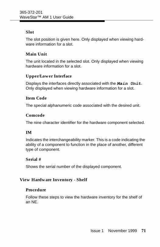
Issue 1 November 1999 71
365-372-201WaveStar™ AM 1 User Guide
Slot
The slot position is given here. Only displayed when viewing hard-ware information for a slot.
Main Unit
The unit located in the selected slot. Only displayed when viewing hardware information for a slot.
Upper/Lower Interface
Displays the interfaces directly associated with the Main Unit. Only displayed when viewing hardware information for a slot.
Item Code
The special alphanumeric code associated with the desired unit.
Comcode
The nine character identifier for the hardware component selected.
IM
Indicates the interchangeability marker. This is a code indicating the ability of a component to function in the place of another, different type of component.
Serial #
Shows the serial number of the displayed component.
View Hardware Inventory - Shelf
Procedure
Follow these steps to view the hardware inventory for the shelf of an NE.

72 Issue 1 November 1999
365-372-201WaveStar™ AM 1 User Guide
1. To view details concerning the shelf, select Provision-ing -> Equipment -> Provisioned NE Compo-nents.
Result: The Provisioned NE Components window appears.
2. Click HW Inv.
Result: The Provisioned NE Hardware Inventory window appears with relevant information concerning the shelf.
3. Click Close.
Result: The Provisioned NE Hardware Inventory window disappears.
4. Click Close.
Result: The Provisioned NE Components window disappears.
View Hardware Inventory - Slot
Procedure
Follow these steps to view the hardware inventory for an NE sub-rack slot.
1. To view hardware details concerning a slot, select Provi-sioning -> Equipment -> Provisioned NE Components.
Result: The Provisioned NE Components window appears.
2. Select a slot from the list Provisioned Slots.
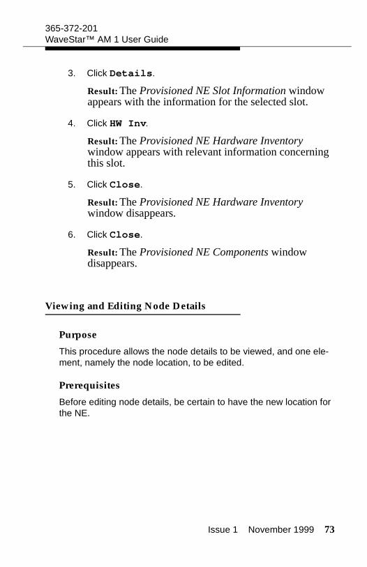
Issue 1 November 1999 73
365-372-201WaveStar™ AM 1 User Guide
3. Click Details.
Result: The Provisioned NE Slot Information window appears with the information for the selected slot.
4. Click HW Inv.
Result: The Provisioned NE Hardware Inventory window appears with relevant information concerning this slot.
5. Click Close.
Result: The Provisioned NE Hardware Inventory window disappears.
6. Click Close.
Result: The Provisioned NE Components window disappears.
Viewing and Editing Node Details
Purpose
This procedure allows the node details to be viewed, and one ele-ment, namely the node location, to be edited.
Prerequisites
Before editing node details, be certain to have the new location for the NE.
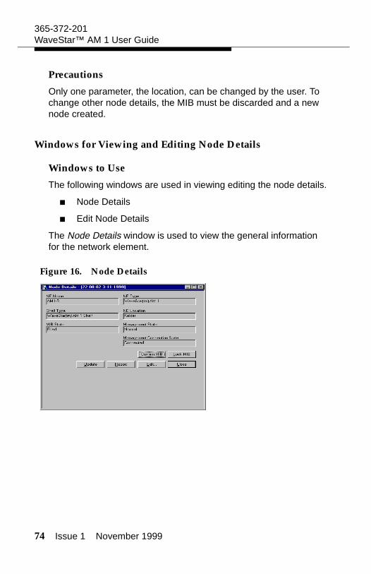
74 Issue 1 November 1999
365-372-201WaveStar™ AM 1 User Guide
Precautions
Only one parameter, the location, can be changed by the user. To change other node details, the MIB must be discarded and a new node created.
Windows for Viewing and Editing Node Details
Windows to Use
The following windows are used in viewing editing the node details.
Node Details
Edit Node Details
The Node Details window is used to view the general information for the network element.
Figure 16. Node Details
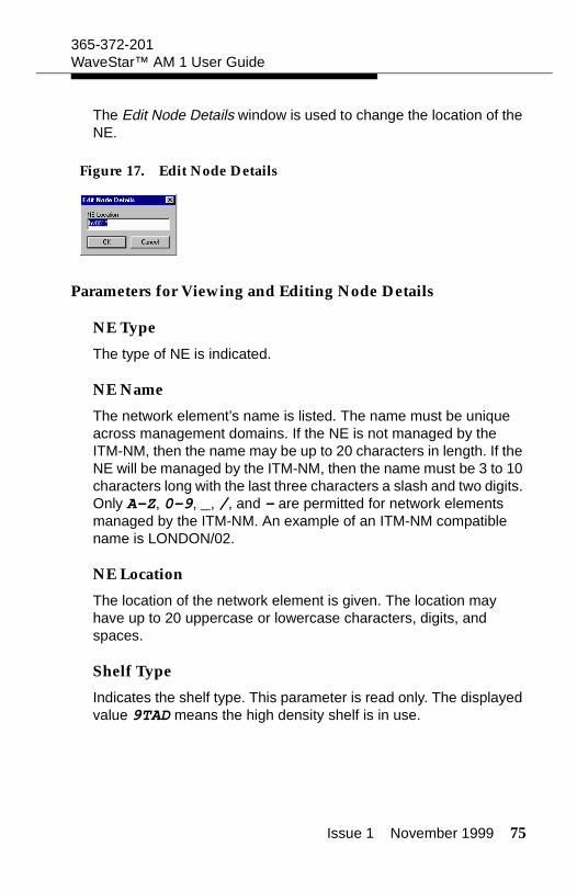
Issue 1 November 1999 75
365-372-201WaveStar™ AM 1 User Guide
The Edit Node Details window is used to change the location of the NE.
Figure 17. Edit Node Details
Parameters for Viewing and Editing Node Details
NE Type
The type of NE is indicated.
NE Name
The network element’s name is listed. The name must be unique across management domains. If the NE is not managed by the ITM-NM, then the name may be up to 20 characters in length. If the NE will be managed by the ITM-NM, then the name must be 3 to 10 characters long with the last three characters a slash and two digits. Only A-Z, 0-9, _, /, and - are permitted for network elements managed by the ITM-NM. An example of an ITM-NM compatible name is LONDON/02.
NE Location
The location of the network element is given. The location may have up to 20 uppercase or lowercase characters, digits, and spaces.
Shelf Type
Indicates the shelf type. This parameter is read only. The displayed value 9TAD means the high density shelf is in use.
76 Issue 1 November 1999
365-372-201WaveStar™ AM 1 User Guide
MIB State
The status of the MIB is indicated. The possible values are given in the table below.
MIB State Description
Empty An empty system controller (SC) has been inserted or the MIB was cleared after starting an MIB download by the management system. If the MIB State is empty, the management system can proceed with the MIB download.
Filled The NE possesses a valid MIB, which has been confirmed.
Filled Unknown
The NE has a MIB, however, it is of unknown validity. This can occur, for instance, if one SC is replaced by another SC having a MIB.
Filled Not Confirmed
The NE has a MIB, however, it has not yet been confirmed by the ITM-CIT or ITM-SC. The procedure "Confirm the MIB" gives the steps necessary to confirm the MIB. Once confirmed the state will become Filled.
Waiting for Upload
This state is only possible when the NE is managed by the ITM-SC. After confirmation of the MIB, the NE performs a reset and loses its association with the ITM-SC. When the NE restarts, the MIB State becomes Waiting for Upload. When the ITM-SC reassociates with the NE and detects this MIB state, an MIB upload is performed, and the state will then become Filled.
Issue 1 November 1999 77
365-372-201WaveStar™ AM 1 User Guide
Management State
The state of the association with the ITM-SC is displayed. The pos-sible states are given in the following table.
Management State
Description
Normal Normal will be displayed whenever management operations have been completed. In other words, the ITM-SC has completed the MIB upload, MIB download, MIB resynchronization, or reevaluation of fault status. The state can also be Normal when the association between the ITM-SC and the ITM-CIT has been lost.
Uploading The ITM-SC is performing an MIB upload.
Resyncing If the MIB of the NE and the MIB image on the ITM-SC are out of synchronization, then the ITM-SC invokes a resynchronization. The management state shows the progress of the this operation. If executed properly, it should display, in order: Normal, Resyncing, Normal, ReEvaluatingFaultStatus, Normal.
ReEvaluating FaultStatus
After a resynchronization, the ITM-SC initiates a reevaluate fault status operation.
78 Issue 1 November 1999
365-372-201WaveStar™ AM 1 User Guide
View and Edit Node Details
Procedure
Follow these steps to change the location of the NE.
1. Select Management -> Node Details.
Result: The Node Details window appears.
2. To change the NE Location, continue with step 3. Otherwise, go to step 6.
3. Click Edit.
Result: The Edit Node Details window appears.
4. Enter the new NE Location.
Result: The correct location now appears in the area provided.
5. Click OK.
Result: The new NE Location is entered, and the window Edit Node Details disappears.
Downloading A MIB download has been started by the ITM-SC. The management state is set to Normal during the downloading process. If the MIB download is in progress when a loss of association occurs, then the management state will remain Downloading.
Management State
Description
Issue 1 November 1999 79
365-372-201WaveStar™ AM 1 User Guide
6. Click Close.
Result: The Node Details window disappears.
Viewing and Editing MDI Information
Purpose
Use this procedure to view and edit MDI names and statuses.
Prerequisites
The WaveStar™ AM 1 contains 4 MDIs.
Also, the miscellaneous discrete input must be connected to the NE.
Precautions
The following precautions should be noted.
The MDI name can be no longer than 26 characters.
There are four MDIs that may be provisioned for an NE.
The user should select names for the Miscellaneous Dis-crete Inputs that are both well-chosen and unique.
Windows for Viewing and Editing MDI Information
Windows to Use
Use the following windows to view and edit MDI information:
Provisioned MDI
Edit Provisioned MDI
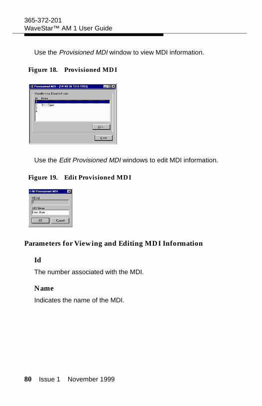
80 Issue 1 November 1999
365-372-201WaveStar™ AM 1 User Guide
Use the Provisioned MDI window to view MDI information.
Figure 18. Provisioned MDI
Use the Edit Provisioned MDI windows to edit MDI information.
Figure 19. Edit Provisioned MDI
Parameters for Viewing and Editing MDI Information
Id
The number associated with the MDI.
Name
Indicates the name of the MDI.
Issue 1 November 1999 81
365-372-201WaveStar™ AM 1 User Guide
View and Edit MDI Information
Procedure
Follow these steps to view and edit MDI names.
1. Select Provisioning -> Equipment -> MDI.
Result: The Provisioned MDI window appears.
2. Select an MDI from the list under ID and Name.
Result: The appropriate MDI is selected.
3. Click Edit.
Result: The Edit Provisioned MDI window is displayed. The current name of the selected MDI is displayed on the name line of this window.
4. Enter the Name (max. 26 characters).
5. Click OK.
Result: The new MDI name is entered and the Edit Provisioned MDI window is closed.
6. Click Close.
Result: The Provisioned MDI window disappears.
Viewing and Editing MDO Information
Purpose
Use this procedure to view and edit MDO names and statuses.
Prerequisites
The WaveStar™ AM 1 contains 4 MDOs.
The miscellaneous discrete output must be connected to the NE.
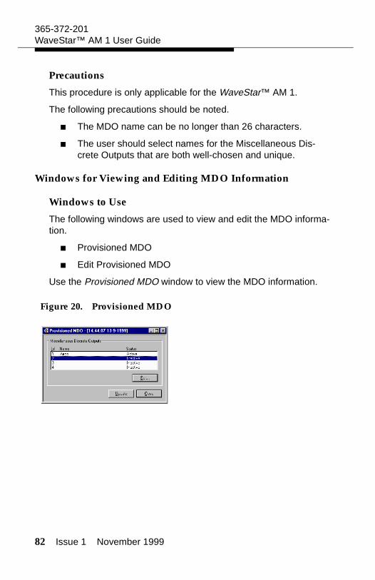
82 Issue 1 November 1999
365-372-201WaveStar™ AM 1 User Guide
Precautions
This procedure is only applicable for the WaveStar™ AM 1.
The following precautions should be noted.
The MDO name can be no longer than 26 characters.
The user should select names for the Miscellaneous Dis-crete Outputs that are both well-chosen and unique.
Windows for Viewing and Editing MDO Information
Windows to Use
The following windows are used to view and edit the MDO informa-tion.
Provisioned MDO
Edit Provisioned MDO
Use the Provisioned MDO window to view the MDO information.
Figure 20. Provisioned MDO

Issue 1 November 1999 83
365-372-201WaveStar™ AM 1 User Guide
Use the Edit Provisioned MDO window to edit the MDO information.
Figure 21. Edit Provisioned MDO
Parameters for Viewing and Editing MDO Information
Id
The number associated with the MDO.
Name
Indicates the name of the MDO.
Status
Indicates the status of the MDO. The possible values are Active and Inactive.
View and Edit MDO Information
Procedure
Follow these steps to view and edit MDO names and statuses.
1. Select Provisioning -> Equipment -> MDO.
Result: The Provisioned MDO window appears.
84 Issue 1 November 1999
365-372-201WaveStar™ AM 1 User Guide
2. Select an MDO from the list under ID and Name.
Result: The appropriate MDO is selected.
3. Click Edit.
Result: The Edit Provisioned MDO window is displayed. The current name of the selected MDO is displayed on the name line of this window.
4. Enter or change the Name (max. 26 characters).
5. Set the Status of the MDO to Active (closed loop) or Inactive (open loop).
Result: The field Status is defined.
6. Click OK.
Result: The new MDO name is entered, and the Edit Provisioned MDO window is closed.
7. Click Close.
Result: The Provisioned MDO window disappears.
Issue 1 November 1999 85
Transmission Provisioning
Intended use
This subsection describes setting up traffic on VC-3 and/or VC-12 level in a network with WaveStar™ AM 1 network elements.
The following tasks can be performed:
Task Purpose
Provision Cross Connections
set up the transmission path.
Provision TUG Structure
enables making cross connections on VC-12 or VC-3 level.
Port Provisioning
configures testing and monitoring of physical input/output signals.
Provision Termination Points
configures testing and monitoring of signals at the logical ports.
Path Trace Provisioning
test the established path.
Provision Signal Degrade Thresholds
define the values at which the signal is considered of degraded quality.
86 Issue 1 November 1999
365-372-201WaveStar™ AM 1 User Guide
Provision Cross Connections
Purpose
To provide traffic over the network, cross connections must be pro-visioned in the network elements. With the WaveStar™ AM 1, the cross connection settings can be modified if the traffic demand changes. The following changes can be made:
Add a cross connection
Modify an existing cross connection
Delete a cross connection.
Prerequisites
Before adding a cross connection and, if desired, its protection be sure to have information regarding the design of the transmission path.
Before deleting a cross connection and/or its protection be sure to have information regarding the soon to-be-removed cross connec-tion. For instance:
Does the cross connection to be removed still carry traffic?
Is the cross connection protected?
Precautions
When provisioning an SNC protected cross connection, the From and Protection termintation points should be associated with the line ports. The To termination point should be associated with a connection point of a tributary port.
Precautions for deleting cross connections or removing their pro-tection are:
Deleting or changing a cross connection may be traffic affecting.
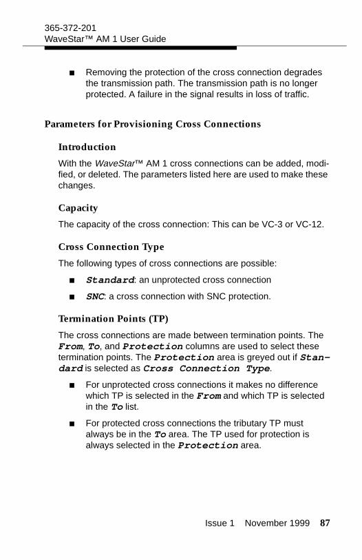
Issue 1 November 1999 87
365-372-201WaveStar™ AM 1 User Guide
Removing the protection of the cross connection degrades the transmission path. The transmission path is no longer protected. A failure in the signal results in loss of traffic.
Parameters for Provisioning Cross Connections
Introduction
With the WaveStar™ AM 1 cross connections can be added, modi-fied, or deleted. The parameters listed here are used to make these changes.
Capacity
The capacity of the cross connection: This can be VC-3 or VC-12.
Cross Connection Type
The following types of cross connections are possible:
Standard: an unprotected cross connection
SNC: a cross connection with SNC protection.
Termination Points (TP)
The cross connections are made between termination points. The From, To, and Protection columns are used to select these termination points. The Protection area is greyed out if Stan-dard is selected as Cross Connection Type.
For unprotected cross connections it makes no difference which TP is selected in the From and which TP is selected in the To list.
For protected cross connections the tributary TP must always be in the To area. The TP used for protection is always selected in the Protection area.
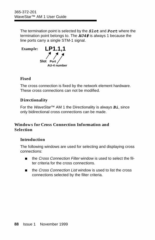
88 Issue 1 November 1999
365-372-201WaveStar™ AM 1 User Guide
The termination point is selected by the Slot and Port where the termination point belongs to. The AU4# is always 1 because the line ports carry a single STM-1 signal.
Example:
Fixed
The cross connection is fixed by the network element hardware. These cross connections can not be modified.
Directionality
For the WaveStar™ AM 1 the Directionality is always Bi, since only bidirectional cross connections can be made.
Windows for Cross Connection Information and Selection
Introduction
The following windows are used for selecting and displaying cross connections:
the Cross Connection Filter window is used to select the fil-ter criteria for the cross connections.
the Cross Connection List window is used to list the cross connections selected by the filter criteria.
LP1.1,1
AU-4 numberPortSlot
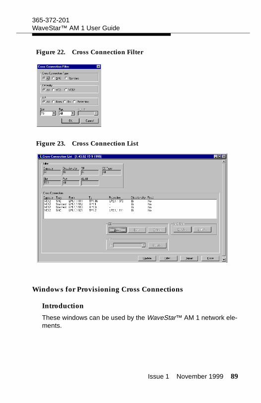
Issue 1 November 1999 89
365-372-201WaveStar™ AM 1 User Guide
Figure 22. Cross Connection Filter
Figure 23. Cross Connection List
Windows for Provisioning Cross Connections
Introduction
These windows can be used by the WaveStar™ AM 1 network ele-ments.
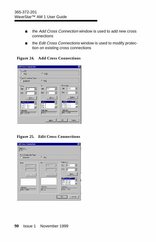
90 Issue 1 November 1999
365-372-201WaveStar™ AM 1 User Guide
the Add Cross Connection window is used to add new cross connections
the Edit Cross Connections window is used to modify protec-tion on existing cross connections
Figure 24. Add Cross Connections
Figure 25. Edit Cross Connections
Issue 1 November 1999 91
365-372-201WaveStar™ AM 1 User Guide
Procedure to Add Cross Connections
Procedure
Use the following procedure to add a cross connection in the Wave-Star™ AM 1 network element.
1. To make a cross connection first determine the following:
What is the capacity of the cross connection? VC-12 or VC-3?
Is the TUG Structure provisioned in such a way that the capacity can be selected? The procedure to check and change the TUG Structure is described in the section "Provision TUG Structure."
Does the cross connection require SNC protection or is it unprotected (Standard)?
Between which termination points (TP) is the cross connection made and which termination point is used for the SNC protection path.
2. Select Provisioning -> Transport -> Cross Connection.
Result: The Cross Connection Filter window and the Cross Connection Selection List window appear at the same time.
3. Select the filter criteria in the Cross Connection Filter window and select OK.
Result: All available cross connections that meet the selected filter criteria are listed in the Cross Connection Selection List window. The filter criteria are displayed in the filter area.
92 Issue 1 November 1999
365-372-201WaveStar™ AM 1 User Guide
4. Select Add in the CC area.
Result: The Add Cross Connection window appears.
5. Select the Capacity and Cross Connection Type. Select the Slot and Port and click select for each ter-mination point in the From, To and Protection fields.
For unprotected cross connections it makes no differ-ence which TP is selected in the From and which TP is selected in the To list.
For protected cross connections the tributary TP must always be in the To area. The TP used for protection is always selected in the Protection area.
Result: A list of available termination points appears for each termination point.
If not all available termination points appear check if the TUG struc-ture is provisioned to make the cross connections on the desired level. Change the TUG Structure if necessary. The procedure to change the TUG Structure is described in the section "Provision TUG structure."
6. Select one TP in each field and select Apply. Select OK if no other cross connections are to be made.
Result: The TPs appear in the Selection boxes. The cross connection between the selected TPs is made. If OK was selected the Add Cross Connection window closes and the new cross connections appear in the list of the Cross Connection List window.
Issue 1 November 1999 93
365-372-201WaveStar™ AM 1 User Guide
Procedure to Modify Existing Cross Connections
Introduction
Use the following procedure to modify protection for an existing cross connection in the WaveStar™ AM 1 network element.
1. To modify an existing cross connection, first determine the following points about the cross connection to be modified and determine what must be changed.
Does the cross connection require SNC protection or is it unprotected (Standard)?
Between which termination points (TP) is the cross connection made and which termination point is used for the SNC protection path.
2. Select Provisioning -> Transport -> Cross Connection.
Result: The Cross Connection Filter window appears.
3. Select the filter criteria and select OK.
Result: The Cross Connection Selection List window appears with all available cross connections that meet the selected filter criteria. The filter criteria are displayed in the filter area of the Cross Connection Selection List window.
4. Select the cross connection to be modified from the list and select Edit in the CC area.
Result: The Edit Cross Connection window appears. All fields are filled in according to the selected cross connection.
94 Issue 1 November 1999
365-372-201WaveStar™ AM 1 User Guide
5. Change, if necessary, the Cross Connection Type and select the Slot, Port, and AU4# . Click Select for each termination point in the From, To, and Protection fields.
For unprotected cross connections it makes no differ-ence which TP is selected in the From and which TP is selected in the To list.
For protected cross connections the tributary TP must always be in the To area. The TP used for protection is always selected in the Protection area.
Result: A list of available termination points appears, including the termination points of the selected cross connection.
6. Select one TP in each field and select OK.
Result: The TPs appear in the Selection boxes. The cross connection between the selected TPs is made. The Edit Cross Connection window closes and the modified cross connection appears in the list of the Cross Connection List window.
Procedure to Delete an Existing Cross Connection
Introduction
Use the following procedure to delete an existing cross connection in the WaveStar™ AM 1 network element.
1. Select Provisioning -> Transport -> Cross Connection.
Result: The Cross Connection Filter window appears.
Issue 1 November 1999 95
365-372-201WaveStar™ AM 1 User Guide
2. Select the filter criteria and select OK.
Result: The Cross Connection Selection List window appears with all available cross connections that meet the selected filter criteria. The filter criteria are displayed in the filter area of the Cross Connection Selection List window.
3. Select the cross connection to be deleted from the list and select Delete in the CC area.
Result: A confirmation window appears.
4. Click Yes to confirm the removal of the cross connection.
Result: The cross connection is removed. The cross connection disappears from the list in the Cross Connection List window.
Provision TUG Structure
Purpose
The purpose of checking or changing the TUG structure of a VC-4 signal is to make it possible to create a path of a certain capacity (for example VC-3 or VC-12 capacity).
Prerequisites
The TUG Structure can only be changed if the changing part is not involved in a cross connection.
For the WaveStar™ AM 1 the TUG structure can only be provi-sioned in the VC-4 termination points of the line ports. The default setting is all TU-12s. Therefore it makes sense to change the TUG structure to TU-3s if 34 Mbit/s units are provisioned.
96 Issue 1 November 1999
365-372-201WaveStar™ AM 1 User Guide
Parameters for Provisioning TUG Structure
Introduction
The WaveStar™ AM 1 can have 2 Mbit/s and 34 Mbit/s ports. Therefore cross connections can be made at VC-3 or VC-12 level. The default setting of the TUG structure is all TU-12s. If the Wave-Star™ AM 1 does not have any 34 Mbit/s ports it makes no sense to change the TUG structure. The WaveStar™ AM 1 can not cross connect unstructured VC-4s, therefor it is not possible to uncheck the TUG Structured TP box.
Usage
Each VC-12 or VC-3 involved in a cross connection is displayed as a filled box. Source and Sink always have the same TUG struc-tures. The filling of the boxes may be different.
Source: The TUG structure of the VC-4 signal in the source direction of the selected TP.
Sink: The TUG structure of the VC-4 signal in the sink direction of the selected TP. TUG2
TUG Structured TP
If the box is checked the VC-4 is substructured and can be divided into TU-12s and/or TU-3s. If the box is not checked the VC-4 is unstructured.
TUG3
For each TUG-3 there is a box. If the box is checked the TUG-3 is substructured into 7 TUG-3s and each TUG-2 is substructured into 3 TU-12s
Issue 1 November 1999 97
365-372-201WaveStar™ AM 1 User Guide
TUG2
Each checked TUG2 box represents a TUG-2 substructured into 3 TU-12s. This part can not be edited, only by changing the above TUG-3 box.
TU3 Only
Defines a substructure of only TU-3s
Full TU12
Defines a substructure of only TU-12s
Windows for Provisioning the TUG Structure
Windows To Use
The following windows are used to provision the TUG Structure:
the Termination Point Filter window is used to select the filter criteria for the termination point list.
the Termination Point List window is used to select the termi-nation point.
the TUG Structure and Usage window displays the TUG structure of the selected VC-4.
the Edit TUG Structure window is used to modify the TUG structure of the selected VC-4.
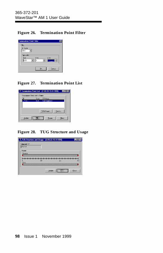
98 Issue 1 November 1999
365-372-201WaveStar™ AM 1 User Guide
Figure 26. Termination Point Filter
Figure 27. Termination Point List
Figure 28. TUG Structure and Usage
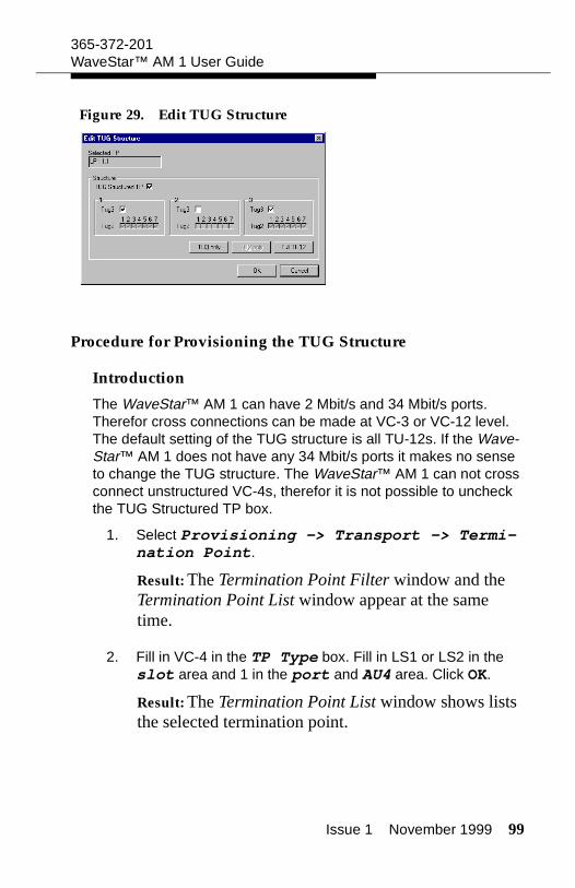
Issue 1 November 1999 99
365-372-201WaveStar™ AM 1 User Guide
Figure 29. Edit TUG Structure
Procedure for Provisioning the TUG Structure
Introduction
The WaveStar™ AM 1 can have 2 Mbit/s and 34 Mbit/s ports. Therefor cross connections can be made at VC-3 or VC-12 level. The default setting of the TUG structure is all TU-12s. If the Wave-Star™ AM 1 does not have any 34 Mbit/s ports it makes no sense to change the TUG structure. The WaveStar™ AM 1 can not cross connect unstructured VC-4s, therefor it is not possible to uncheck the TUG Structured TP box.
1. Select Provisioning -> Transport -> Termi-nation Point.
Result: The Termination Point Filter window and the Termination Point List window appear at the same time.
2. Fill in VC-4 in the TP Type box. Fill in LS1 or LS2 in the slot area and 1 in the port and AU4 area. Click OK.
Result: The Termination Point List window shows lists the selected termination point.
100 Issue 1 November 1999
365-372-201WaveStar™ AM 1 User Guide
3. Select the termination point and click TUG Struct.
Result: The TUG Structure and Usage window appears and displays the TUG structure of the selected termination point
4. Click Edit.
Result: The Edit TUG Structure window appears.
5. Change the TUG structure by clicking the check boxes or by clicking TU3 only or Full TU12. Click OK.
Result: The modified TUG structure is displayed in the TUG Structure and Usage window.
Port Provisioning
Purpose
The purpose of port provisioning is to get an overview of all the physical ports of the network element and to change the settings of these ports. The provisioning of timing ports is described in the chapter "Provisioning Timing" of this guide.
Prerequisites
Before starting to modify NE ports it is assumed that:
information about which port on which unit needs to be mod-ified is available
There is no traffic on the ports that you want to test with a loopback.
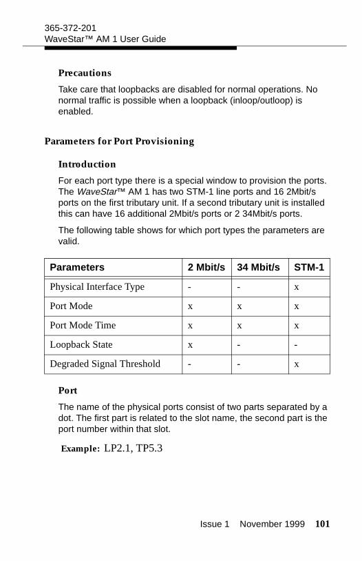
Issue 1 November 1999 101
365-372-201WaveStar™ AM 1 User Guide
Precautions
Take care that loopbacks are disabled for normal operations. No normal traffic is possible when a loopback (inloop/outloop) is enabled.
Parameters for Port Provisioning
Introduction
For each port type there is a special window to provision the ports. The WaveStar™ AM 1 has two STM-1 line ports and 16 2Mbit/s ports on the first tributary unit. If a second tributary unit is installed this can have 16 additional 2Mbit/s ports or 2 34Mbit/s ports.
The following table shows for which port types the parameters are valid.
Port
The name of the physical ports consist of two parts separated by a dot. The first part is related to the slot name, the second part is the port number within that slot.
Example: LP2.1, TP5.3
Parameters 2 Mbit/s 34 Mbit/s STM-1
Physical Interface Type - - x
Port Mode x x x
Port Mode Time x x x
Loopback State x - -
Degraded Signal Threshold - - x
102 Issue 1 November 1999
365-372-201WaveStar™ AM 1 User Guide
Type
The Type indicates the type of signal for which the port is an inter-face point.
Example: 2 Mbit/s, 34 Mbit/s, STM-1.
Physical Interface Type
STM-1 ports can be Optical or Electrical.
Port Mode
The Port Mode controls whether input signals should be moni-tored or not. The following values can be set.
Value Description
Monitored The port is configured to provide service and the port signal is monitored.
Auto The port is configured not to provide service yet. Use this mode when the signal source in the remote NE is not operational yet. As soon as the NE establishes the continuous presence of a fault-free signal for a certain period (Port Mode Time), the port automatically changes to Monitored.
Not Monitored
The port is configured not to monitor the port signal on the port. No alarms are generated for this port. If there still is a signal present on the not monitored port it is possible to receive a Not Expected Input Signal (NES) alarm. The alarm status of NES must then be provisioned Reported.
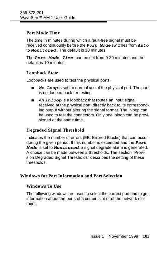
Issue 1 November 1999 103
365-372-201WaveStar™ AM 1 User Guide
Port Mode Time
The time in minutes during which a fault-free signal must be received continuously before the Port Mode switches from Auto to Monitored.. The default is 10 minutes.
The Port Mode Time can be set from 0-30 minutes and the default is 10 minutes.
Loopback State
Loopbacks are used to test the physical ports.
No Loop is set for normal use of the physical port. The port is not looped back for testing
An Inloop is a loopback that routes an input signal, received at the physical port, directly back to its correspond-ing output without altering the signal format. The inloop can be used to test the connectors. Only one inloop can be provi-sioned at the same time.
Degraded SIgnal Threshold
Indicates the number of errors (EB: Errored Blocks) that can occur during the given period. If this number is exceeded and the Port Mode is set to Monitored, a signal degrade alarm is generated. A choice can be made between 2 thresholds. The section "Provi-sion Degraded Signal Thresholds" describes the setting of these thresholds.
Windows for Port Information and Port Selection
Windows To Use
The following windows are used to select the correct port and to get information about the ports of a certain slot or of the network ele-ment.
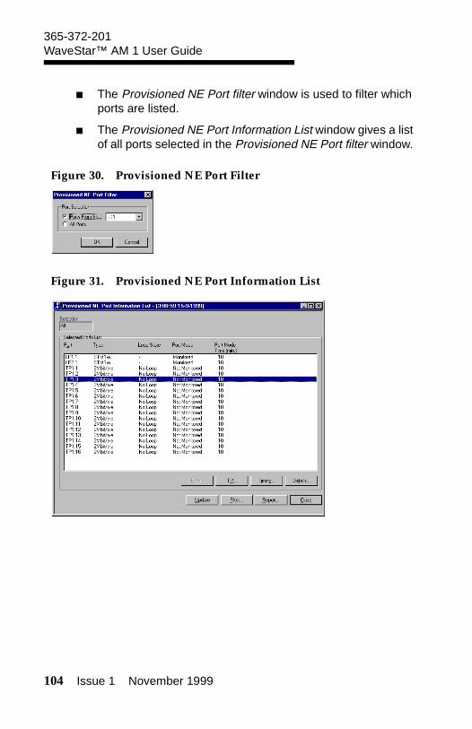
104 Issue 1 November 1999
365-372-201WaveStar™ AM 1 User Guide
The Provisioned NE Port filter window is used to filter which ports are listed.
The Provisioned NE Port Information List window gives a list of all ports selected in the Provisioned NE Port filter window.
Figure 30. Provisioned NE Port Filter
Figure 31. Provisioned NE Port Information List
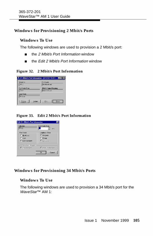
Issue 1 November 1999 105
365-372-201WaveStar™ AM 1 User Guide
Windows for Provisioning 2 Mbit/s Ports
Windows To Use
The following windows are used to provision a 2 Mbit/s port:
the 2 Mbit/s Port Information window
the Edit 2 Mbit/s Port Information window
Figure 32. 2 Mbit/s Port Information
Figure 33. Edit 2 Mbit/s Port Information
Windows for Provisioning 34 Mbit/s Ports
Windows To Use
The following windows are used to provision a 34 Mbit/s port for the WaveStar™ AM 1:
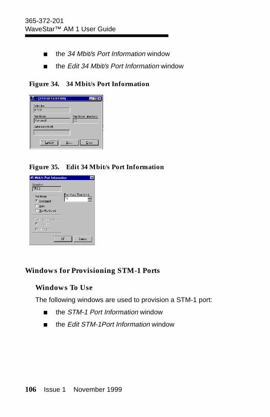
106 Issue 1 November 1999
365-372-201WaveStar™ AM 1 User Guide
the 34 Mbit/s Port Information window
the Edit 34 Mbit/s Port Information window
Figure 34. 34 Mbit/s Port Information
Figure 35. Edit 34 Mbit/s Port Information
Windows for Provisioning STM-1 Ports
Windows To Use
The following windows are used to provision a STM-1 port:
the STM-1 Port Information window
the Edit STM-1Port Information window
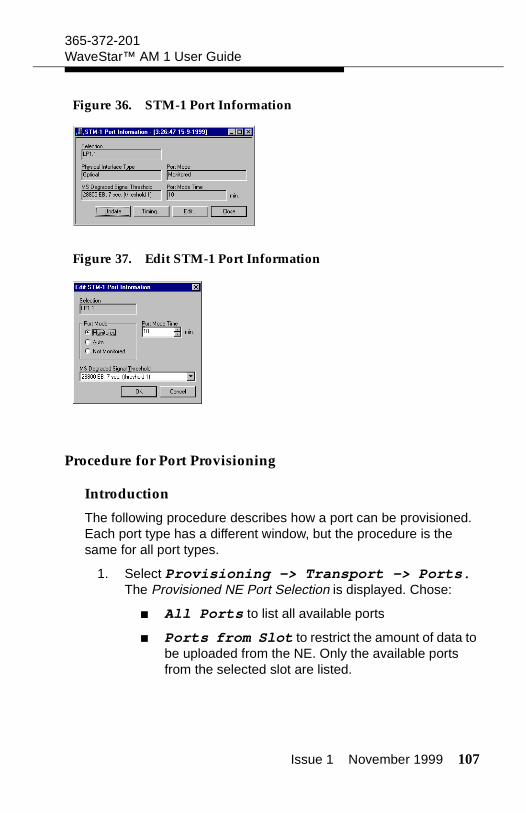
Issue 1 November 1999 107
365-372-201WaveStar™ AM 1 User Guide
Figure 36. STM-1 Port Information
Figure 37. Edit STM-1 Port Information
Procedure for Port Provisioning
Introduction
The following procedure describes how a port can be provisioned. Each port type has a different window, but the procedure is the same for all port types.
1. Select Provisioning -> Transport -> Ports. The Provisioned NE Port Selection is displayed. Chose:
All Ports to list all available ports
Ports from Slot to restrict the amount of data to be uploaded from the NE. Only the available ports from the selected slot are listed.
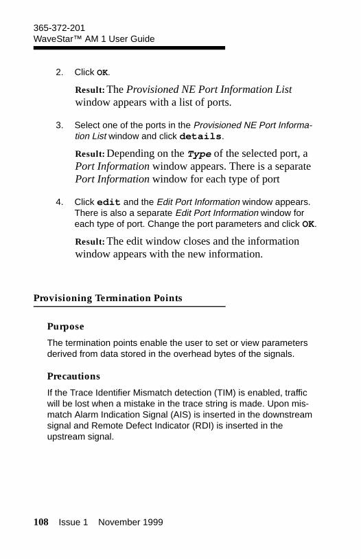
108 Issue 1 November 1999
365-372-201WaveStar™ AM 1 User Guide
2. Click OK.
Result: The Provisioned NE Port Information List window appears with a list of ports.
3. Select one of the ports in the Provisioned NE Port Informa-tion List window and click details.
Result: Depending on the Type of the selected port, a Port Information window appears. There is a separate Port Information window for each type of port
4. Click edit and the Edit Port Information window appears. There is also a separate Edit Port Information window for each type of port. Change the port parameters and click OK.
Result: The edit window closes and the information window appears with the new information.
Provisioning Termination Points
Purpose
The termination points enable the user to set or view parameters derived from data stored in the overhead bytes of the signals.
Precautions
If the Trace Identifier Mismatch detection (TIM) is enabled, traffic will be lost when a mistake in the trace string is made. Upon mis-match Alarm Indication Signal (AIS) is inserted in the downstream signal and Remote Defect Indicator (RDI) is inserted in the upstream signal.
Issue 1 November 1999 109
365-372-201WaveStar™ AM 1 User Guide
Parameters for Provisioning Termination Points
Introduction
The following Termination Points can be provisioned:
WaveStar™ AM 1: VC-12, VC-3, VC-4, TU-12, TU-3 and AU-4.
Selected TP
The name of the selected termination point.
The termination point is selected by the Slot and Port where the termination point belongs to. The AU4# is always 1 because the line ports carry STM-1 signals.
The name of the termination points consist of the physical port name (slot name and port number) followed by the AU-4 number and for low order signals, the VC number (VC-12 or VC-3). The VC number consists of:
the number of the TUG-3 inside the VC-4
the number of the TUG-2 inside the TUG-3
the TU-12 number inside the TUG-2.
Example:
TP Type
The termination point type indicates where the signal is terminated.
Example: VC-12, VC-3, TU-3, AU-4
LP1.1,1.112
AU-4 number
VC-12 (-3) number
112TUG-3TUG-2
TU-12
VC-12: 100TUG-3
VC-3:
PortSlot
110 Issue 1 November 1999
365-372-201WaveStar™ AM 1 User Guide
TP Mode
Indicates whether the signal on the termination point will be moni-tored.
When Monitored alarms are generated related to the selected termination point. When Not Monitored no alarms are gener-ated for the selected termination point.
J0/J1/J2 Trail Trace Identifier
This area is used to provision a path trace. Provisioning a path trace is described in the section "Path Trace Provisioning."
Signal Label
The signal label is part of the path overhead of a VC-n signal and indicates what type of signal is carried by the container.
Example: Unequipped, asynchronous, TUG structure, ATM
Signal Label Accepted (HEX., Descrip-tion) is the signal label of the received signal
Signal Label Transmit (HEX., Descrip-tion) is the signal label of the transmitted signal
Windows for Provisioning Termination Points
Windows To Use
The following windows are used to provision termination points:
the Termination Point Filter window is used to select the ter-mination point type and location
the Termination Point List window is used to select the termi-nation point
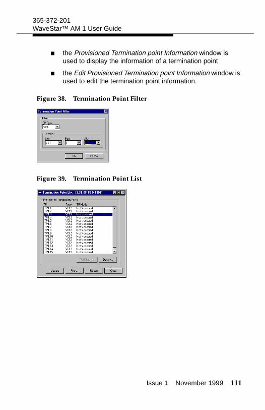
Issue 1 November 1999 111
365-372-201WaveStar™ AM 1 User Guide
the Provisioned Termination point Information window is used to display the information of a termination point
the Edit Provisioned Termination point Information window is used to edit the termination point information.
Figure 38. Termination Point Filter
Figure 39. Termination Point List
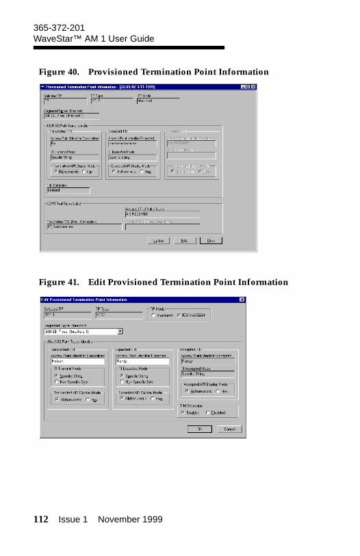
112 Issue 1 November 1999
365-372-201WaveStar™ AM 1 User Guide
Figure 40. Provisioned Termination Point Information
Figure 41. Edit Provisioned Termination Point Information
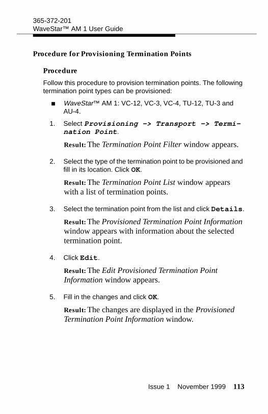
Issue 1 November 1999 113
365-372-201WaveStar™ AM 1 User Guide
Procedure for Provisioning Termination Points
Procedure
Follow this procedure to provision termination points. The following termination point types can be provisioned:
WaveStar™ AM 1: VC-12, VC-3, VC-4, TU-12, TU-3 and AU-4.
1. Select Provisioning -> Transport -> Termi-nation Point.
Result: The Termination Point Filter window appears.
2. Select the type of the termination point to be provisioned and fill in its location. Click OK.
Result: The Termination Point List window appears with a list of termination points.
3. Select the termination point from the list and click Details.
Result: The Provisioned Termination Point Information window appears with information about the selected termination point.
4. Click Edit.
Result: The Edit Provisioned Termination Point Information window appears.
5. Fill in the changes and click OK.
Result: The changes are displayed in the Provisioned Termination Point Information window.

114 Issue 1 November 1999
365-372-201WaveStar™ AM 1 User Guide
Path Trace Provisioning
Purpose
The purpose of provisioning a path trace is to make sure the traffic is not delivered to the wrong destination.
Prerequisites
Before provisioning a path trace determine the following:
In which termination point is the path trace inserted and in which termination points is it monitored?
Which label is used as path trace?
Precautions
If the Trace Identifier Mismatch (TIM) detection is enabled, traffic will be lost when a mistake in the trace string is made. Upon mis-match, an Alarm Indication Signal (AIS) is inserted in the down-stream signal and Remote Defect Indicator (RDI) is inserted in the upstream signal
Parameters for Path Trace Provisioning
Introduction
To make sure the traffic is not delivered to the wrong destination, a path trace can be set. A label (TTI), for example a word, is inserted in the path overhead. To check if the path is correctly provisioned, the received path trace is compared with the expected value. For the WaveStar™ AM 1 a path trace can be set on the VC-12, VC-3 and VC-4 signals.
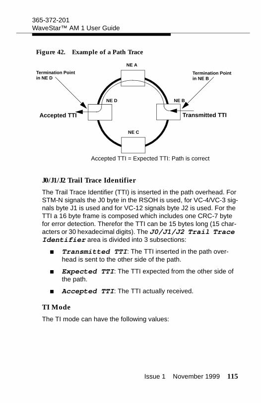
Issue 1 November 1999 115
365-372-201WaveStar™ AM 1 User Guide
Figure 42. Example of a Path Trace
J0/J1/J2 Trail Trace Identifier
The Trail Trace Identifier (TTI) is inserted in the path overhead. For STM-N signals the J0 byte in the RSOH is used, for VC-4/VC-3 sig-nals byte J1 is used and for VC-12 signals byte J2 is used. For the TTI a 16 byte frame is composed which includes one CRC-7 byte for error detection. Therefor the TTI can be 15 bytes long (15 char-acters or 30 hexadecimal digits). The J0/J1/J2 Trail Trace Identifier area is divided into 3 subsections:
Transmitted TTI: The TTI inserted in the path over-head is sent to the other side of the path.
Expected TTI: The TTI expected from the other side of the path.
Accepted TTI: The TTI actually received.
TI Mode
The TI mode can have the following values:
NE A
NE D
NE C
NE B
Termination Point in NE D
Termination Point in NE B
Accepted TTI Transmitted TTI
Accepted TTI = Expected TTI: Path is correct
116 Issue 1 November 1999
365-372-201WaveStar™ AM 1 User Guide
Specific String: The TTI is a string with maximum length of 15 bytes. This string is identified in the Access Point Identifier (API). In Alphanumeric mode any alpha-numeric character can be used, in HEX mode only 00 .. 7F can be used.
Non Specific Byte: The Trace Identifier matches if it is any constant byte value within the range 00 .. FF. If the byte value is not constant, Trace Identifier Mismatch is assumed. No check between Accepted TTI and Expected TTI is per-formed.
API
The Access Point Identifier (API) is the label that is inserted in the path overhead. This is not valid if the TI Mode is set to Non Specific Byte.
API Display Mode
As long as the characters forming the API are alphanumeric char-acters, it is possible to toggle between HEX and Alphanumeric mode. The accepted API displays non-alphanumeric characters as question marks in the Alphanumeric mode.
TIM Detection
TIM is Trace Identifier Mismatch comparison between the expected and accepted TTI. If this is enabled and the TTIs do not match, a Path Trace Identifier Mismatch alarm is raised.
! WARNING:If the Trace Identifier Mismatch (TIM) detection is enabled, traffic will be lost when a mistake in the trace string is made. Upon mismatch, an Alarm Indication Signal (AIS) is inserted in the downstream signal and Remote Defect Indicator (RDI) is inserted in the upstream signal
Issue 1 November 1999 117
365-372-201WaveStar™ AM 1 User Guide
Windows used for Path Trace Provisioning
Windows To Use
The following windows are used to provision a path trace:
the Provisioned Termination point Information window is used to display the information of a termination point. The information about the path trace is displayed in the J0/J1/J2 Trail Trace Identifier area
the Edit Provisioned Termination Point Information window is used to edit the termination point information. The path trace settings can be entered in the J0/J1/J2 Trail Trace Identifier area
Figure 43. Provisioned Termination Point Information
118 Issue 1 November 1999
365-372-201WaveStar™ AM 1 User Guide
Figure 44. Edit Provisioned Termination Point Information
Procedure to Provision a Path Trace
Introduction
Use the following procedure to provision a path trace. For the WaveStar™ AM 1 a path trace can be set on the VC-12, VC-3, and VC-4 signals.
1. Determine where the termination points of the path are located. If a specific string (API) is used determine the con-tent of the label.
2. Select Provisioning -> Transport -> Termi-nation Point.
Result: The Termination Point Filter window appears.
Issue 1 November 1999 119
365-372-201WaveStar™ AM 1 User Guide
3. Select the type of the termination point for which the path trace must be provisioned and fill in its location. Click OK.
Result: The Termination Point List window appears with a list of termination points.
4. Select the termination point from the list and click Details.
Result: The Provisioned Termination Point Information window appears with information about the selected termination point. The information about the path trace is displayed in the J0/J1/J2 Trail Trace Identifier area.
5. Click Edit.
Result: The Edit Provisioned Termination Point Information window appears.
6. Fill in the label used to be transmitted as path trace and/or the label that is expected to be received. If no label is used select Non Specific Byte. Check if the accepted path trace is the same as the expected path trace and enable or disable the TIM detection if necessary. Click OK.
! WARNING:If the Trace Identifier Mismatch (TIM) detection is enabled, traffic will be lost when a mistake in the trace string is made. Upon mismatch, an Alarm Indication Signal (AIS) is inserted in the downstream signal and Remote Defect Indicator (RDI) is inserted in the upstream signal
Result: The path trace is provisioned and displayed in the Provisioned Termination Point Information window. If the expected TTI equals the accepted TTI, the transmission path is well provisioned.

120 Issue 1 November 1999
365-372-201WaveStar™ AM 1 User Guide
Provision Degraded Signal Thresholds
Purpose
The purpose of provisioning degraded signal thresholds is to define how many errors a signal may have before it is considered degraded. A degraded signal causes a Moderate Block Error Rate alarm. On VC-3 or VC-12 level, a degraded signal can cause an SNC protection switch.
Prerequisites
The threshold values (number of errored blocks and number of sec-onds) must be known.
Precautions
Changing the values of the Signal Degrade Thresholds can degrade the transmission path. Depending on these values alarms are generated and SNC protection switches are made.
Parameters for Provisioning Degraded Signal Thresholds
Introduction
A Degraded signal is a signal with more Errored Blocks (EB) per second than the defined EB Count value during a period of con-secutive seconds defined in Duration (sec). A degraded sig-nal causes a Moderate Block Error Rate alarm. On VC-3 or VC-12 level, a degraded signal causes an SNC protection switch.
Degraded Signal Thresholds
Two Thresholds can be defined for each signal level to declare a signal degraded. The thresholds are called Threshold 1 and Threshold 2. A choice between these two thresholds can be made in the Edit STM-1 Port Information window for the STM-1 sig-nal and in the Edit Provisioned Termination Point window for the VC-4, VC-3, and VC-12 signal.
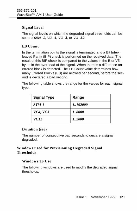
Issue 1 November 1999 121
365-372-201WaveStar™ AM 1 User Guide
Signal Level
The signal levels on which the degraded signal thresholds can be set are STM-1, VC-4, VC-3, or VC-12.
EB Count
In the termination points the signal is terminated and a Bit Inter-leaved Parity (BIP) check is performed on the received data. The result of this BIP check is compared to the values in the B or V5 bytes in the overhead of the signal. When there is a difference an errored block is detected. The EB Count value determines how many Errored Blocks (EB) are allowed per second, before the sec-ond is declared a bad second.
The following table shows the range for the values for each signal type.
Duration (sec)
The number of consecutive bad seconds to declare a signal degraded.
Windows used for Provisioning Degraded Signal Thresholds
Windows To Use
The following windows are used to modify the degraded signal thresholds.
Signal Type Range
STM-1 1..192000
VC4, VC3 1..8000
VC12 1..2000
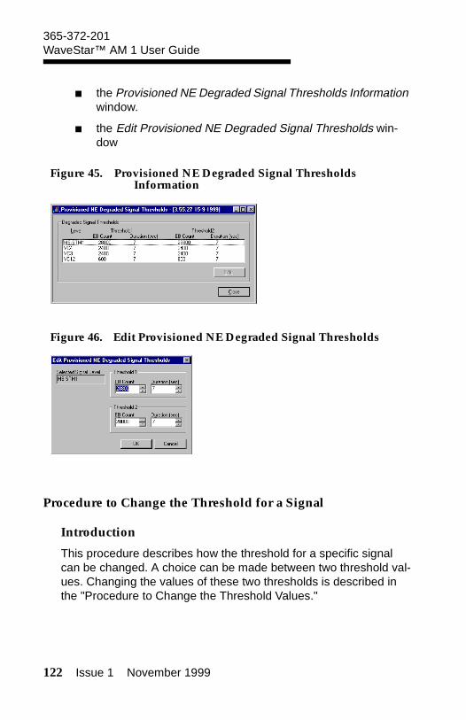
122 Issue 1 November 1999
365-372-201WaveStar™ AM 1 User Guide
the Provisioned NE Degraded Signal Thresholds Information window.
the Edit Provisioned NE Degraded Signal Thresholds win-dow
Figure 45. Provisioned NE Degraded Signal Thresholds Information
Figure 46. Edit Provisioned NE Degraded Signal Thresholds
Procedure to Change the Threshold for a Signal
Introduction
This procedure describes how the threshold for a specific signal can be changed. A choice can be made between two threshold val-ues. Changing the values of these two thresholds is described in the "Procedure to Change the Threshold Values."
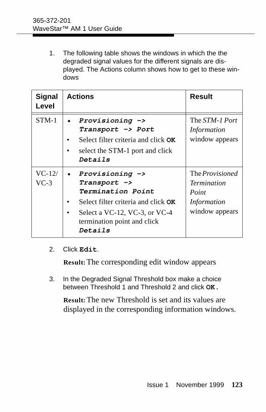
Issue 1 November 1999 123
365-372-201WaveStar™ AM 1 User Guide
1. The following table shows the windows in which the the degraded signal values for the different signals are dis-played. The Actions column shows how to get to these win-dows
2. Click Edit.
Result: The corresponding edit window appears
3. In the Degraded Signal Threshold box make a choice between Threshold 1 and Threshold 2 and click OK.
Result: The new Threshold is set and its values are displayed in the corresponding information windows.
Signal Level
Actions Result
STM-1 • Provisioning -> Transport -> Port
• Select filter criteria and click OK
• select the STM-1 port and click Details
The STM-1 Port Information window appears
VC-12/VC-3
• Provisioning -> Transport -> Termination Point
• Select filter criteria and click OK
• Select a VC-12, VC-3, or VC-4 termination point and click Details
The Provisioned Termination Point Information window appears

124 Issue 1 November 1999
365-372-201WaveStar™ AM 1 User Guide
Issue 1 November 1999 125
Transmission Protection
Intended use
The following subjects are part of transmission protection:
Sub Network Connection protection protects a specific trans-mission path in a ring. (SNC)
Multiplex Section protection protects the transmission path in a point-to-point connection. (MSP)
View SNC Protection
Purpose
To view the SNC connectivity information in the selected network.
Parameters for Viewing SNC Protection
Capacity box
This selection allows the user to filter on particular cross connect capacities. Values are: All, VC-3, and VC-12.
Slot
For All and VC-12 level the value is either TS1 or TS2. For VC-3 the Slot selection is greyed out.
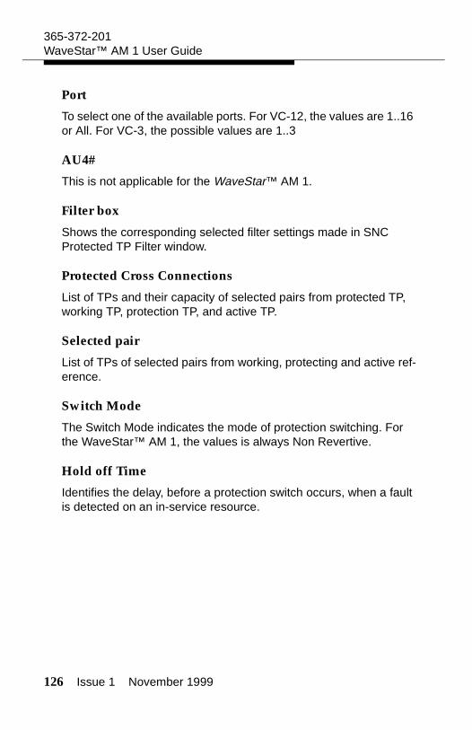
126 Issue 1 November 1999
365-372-201WaveStar™ AM 1 User Guide
Port
To select one of the available ports. For VC-12, the values are 1..16 or All. For VC-3, the possible values are 1..3
AU4#
This is not applicable for the WaveStar™ AM 1.
Filter box
Shows the corresponding selected filter settings made in SNC Protected TP Filter window.
Protected Cross Connections
List of TPs and their capacity of selected pairs from protected TP, working TP, protection TP, and active TP.
Selected pair
List of TPs of selected pairs from working, protecting and active ref-erence.
Switch Mode
The Switch Mode indicates the mode of protection switching. For the WaveStar™ AM 1, the values is always Non Revertive.
Hold off Time
Identifies the delay, before a protection switch occurs, when a fault is detected on an in-service resource.
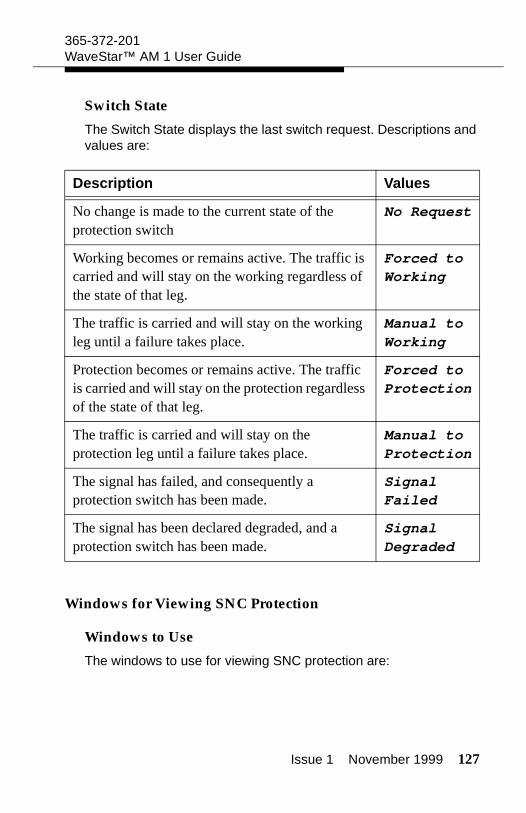
Issue 1 November 1999 127
365-372-201WaveStar™ AM 1 User Guide
Switch State
The Switch State displays the last switch request. Descriptions and values are:
Windows for Viewing SNC Protection
Windows to Use
The windows to use for viewing SNC protection are:
Description Values
No change is made to the current state of the protection switch
No Request
Working becomes or remains active. The traffic is carried and will stay on the working regardless of the state of that leg.
Forced to Working
The traffic is carried and will stay on the working leg until a failure takes place.
Manual to Working
Protection becomes or remains active. The traffic is carried and will stay on the protection regardless of the state of that leg.
Forced to Protection
The traffic is carried and will stay on the protection leg until a failure takes place.
Manual to Protection
The signal has failed, and consequently a protection switch has been made.
Signal Failed
The signal has been declared degraded, and a protection switch has been made.
Signal Degraded
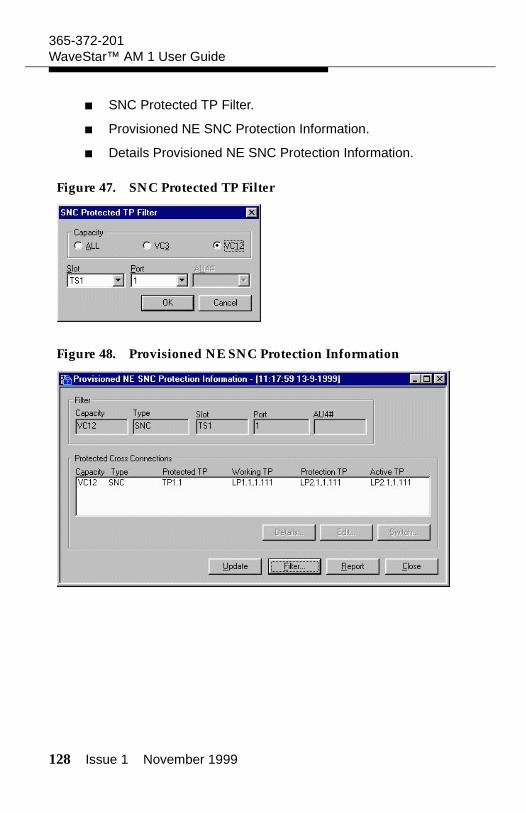
128 Issue 1 November 1999
365-372-201WaveStar™ AM 1 User Guide
SNC Protected TP Filter.
Provisioned NE SNC Protection Information.
Details Provisioned NE SNC Protection Information.
Figure 47. SNC Protected TP Filter
Figure 48. Provisioned NE SNC Protection Information
Issue 1 November 1999 129
365-372-201WaveStar™ AM 1 User Guide
Figure 49. Details Provisioned NE SNC Protection Information
View SNC Protection
Procedure
Follow these steps to view SNC protection information:
1. Select Protection -> Transmission -> SNC.
Result: The SNC Protected TP Filter window is displayed.
2. Make a selection and click OK.
Result: The Provisioned NE SNC Protection Information window is displayed.
3. Make a selection from the list and click Details.
Result: The Details Provisioned NE SNC Protection Information window is displayed.
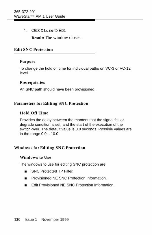
130 Issue 1 November 1999
365-372-201WaveStar™ AM 1 User Guide
4. Click Close to exit.
Result: The window closes.
Edit SNC Protection
Purpose
To change the hold off time for individual paths on VC-3 or VC-12 level.
Prerequisites
An SNC path should have been provisioned.
Parameters for Editing SNC Protection
Hold Off Time
Provides the delay between the moment that the signal fail or degrade condition is set, and the start of the execution of the switch-over. The default value is 0.0 seconds. Possible values are in the range 0.0 .. 10.0.
Windows for Editing SNC Protection
Windows to Use
The windows to use for editing SNC protection are:
SNC Protected TP Filter.
Provisioned NE SNC Protection Information.
Edit Provisioned NE SNC Protection Information.
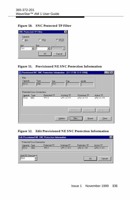
Issue 1 November 1999 131
365-372-201WaveStar™ AM 1 User Guide
Figure 50. SNC Protected TP Filter
Figure 51. Provisioned NE SNC Protection Information
Figure 52. Edit Provisioned NE SNC Protection Information
132 Issue 1 November 1999
365-372-201WaveStar™ AM 1 User Guide
Edit SNC Protection
Procedure
Follow these steps to edit SNC protection:
1. Select Protection -> Transmission -> SNC.
Result: The SNC Protected TP Filter window is displayed.
2. Make a selection and click OK.
Result: The Provisioned NE SNC Protection Information window is displayed.
3. Make a selection from the list and click Edit.
Result: The Edit Provisioned NE SNC Protection Information window is displayed.
4. Make a selection for the Hold Off Time with usage of the above parameter information and click OK.
Result: The edit window closes and the information window is again displayed.
5. Click Close to exit.
Result: The window closes.
Switch SNC Protection
Purpose
To switch protection for individual paths on VC-3 or VC-12 level.

Issue 1 November 1999 133
365-372-201WaveStar™ AM 1 User Guide
Precautions
A protection switch is always traffic affecting.
Prerequisites
An SNC path should have been provisioned.
Parameters for Switching SNC Protection
Switch Request
The Switch Request descriptions and values are:
Description Values
Executing Clear on a line will undo only the previous switch request that are initiated on that specific line.
Clear
Will switch the traffic to the working regardless of the state of that leg. This will override a hardware protection switch. This is canceled with the clear command.
Forced to Working
Will switch the traffic to the protection regardless of the state of that leg. This will override a hardware protection switch. This is canceled with the clear command.
Forced to Protection
Will switch traffic to the working only when that working is error free and is not servicing an equal or higher priority request. An internal or a forced protection switch will override.
Manual to Working
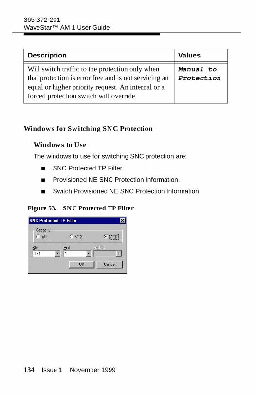
134 Issue 1 November 1999
365-372-201WaveStar™ AM 1 User Guide
Windows for Switching SNC Protection
Windows to Use
The windows to use for switching SNC protection are:
SNC Protected TP Filter.
Provisioned NE SNC Protection Information.
Switch Provisioned NE SNC Protection Information.
Figure 53. SNC Protected TP Filter
Will switch traffic to the protection only when that protection is error free and is not servicing an equal or higher priority request. An internal or a forced protection switch will override.
Manual to Protection
Description Values
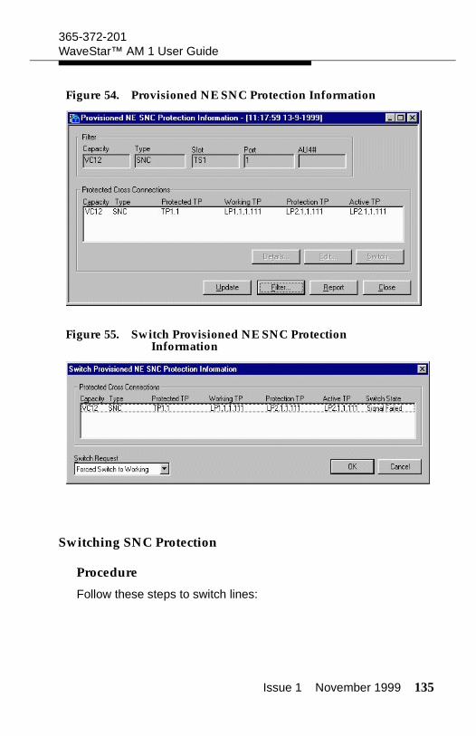
Issue 1 November 1999 135
365-372-201WaveStar™ AM 1 User Guide
Figure 54. Provisioned NE SNC Protection Information
Figure 55. Switch Provisioned NE SNC Protection Information
Switching SNC Protection
Procedure
Follow these steps to switch lines:
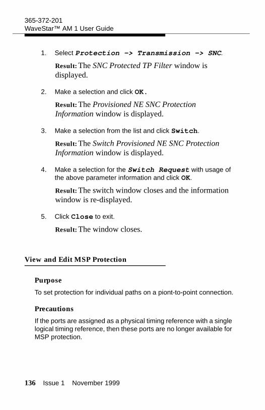
136 Issue 1 November 1999
365-372-201WaveStar™ AM 1 User Guide
1. Select Protection -> Transmission -> SNC.
Result: The SNC Protected TP Filter window is displayed.
2. Make a selection and click OK.
Result: The Provisioned NE SNC Protection Information window is displayed.
3. Make a selection from the list and click Switch.
Result: The Switch Provisioned NE SNC Protection Information window is displayed.
4. Make a selection for the Switch Request with usage of the above parameter information and click OK.
Result: The switch window closes and the information window is re-displayed.
5. Click Close to exit.
Result: The window closes.
View and Edit MSP Protection
Purpose
To set protection for individual paths on a piont-to-point connection.
Precautions
If the ports are assigned as a physical timing reference with a single logical timing reference, then these ports are no longer available for MSP protection.
Issue 1 November 1999 137
365-372-201WaveStar™ AM 1 User Guide
Prerequisites
Prerequisites are:
MSP pair must be present physically set up on the Near End and Far End Network Elements. In other words, the fiber pairs connected on both Network Elements.
Parameters for Viewing and Editing MSP Protection
Working Section
Displays the group of sections defined as working.
Protection Section
Displays the group of sections defined as protection.
Active Section
Displays which section is carrying traffic.
Switch State
Displays the current switch state of the protection pair.
Selected Pair
Displays the selected sections and indicates the alarm status at the working/protection port. This can be Error Free, Failed or Degraded.
Communication Mode
Displays whether the protection is Uni-Directional or Bi-Directional. In the case of failure in the Uni-Directional mode the receive side switches. In the Bi-Directional mode both sides are switched. When the Uni-Directional mode is displayed the Far End selection is greyed out.
138 Issue 1 November 1999
365-372-201WaveStar™ AM 1 User Guide
Switch Mode
Switch Mode displays whether the protection is Revertive or Non-Revertive. In the case of failure with Revertive mode the traffic switches to the protected line and switches back when the failure is solved. In the Non-Revertive mode the traffic switches to the pro-tected line and remains even when the failure is solved.
Switch State
Displays the switch state for MSP.
Description Values
No change is made to the current state of the protection switch
No Request
Switch request which conditionally switches service to the working line. In case a failure is detected an automatic switch will take place to the protected line.
Manual Switch to Working
Switch request which conditionally switches service to the protecting line. In case a failure is detected an automatic switch will take place to the working line.
Manual Switch to Protection
Switch request which enforces switching service to the working line. It prevents automatic switching to the protecting line even in case a failure is detected.
Forced Switch to Working
Switch request which enforces switching service to the protecting line. It prevents automatic switching to the working line even in case a failure is detected.
Forced Switch to Protection
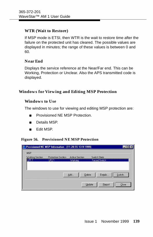
Issue 1 November 1999 139
365-372-201WaveStar™ AM 1 User Guide
WTR (Wait to Restore)
If MSP mode is ETSI, then WTR is the wait to restore time after the failure on the protected unit has cleared. The possible values are displayed in minutes; the range of these values is between 0 and 60.
Near End
Displays the service reference at the Near/Far end. This can be Working, Protection or Unclear. Also the APS transmitted code is displayed.
Windows for Viewing and Editing MSP Protection
Windows to Use
The windows to use for viewing and editing MSP protection are:
Provisioned NE MSP Protection.
Details MSP.
Edit MSP.
Figure 56. Provisioned NE MSP Protection
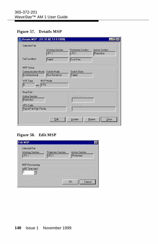
140 Issue 1 November 1999
365-372-201WaveStar™ AM 1 User Guide
Figure 57. Details MSP
Figure 58. Edit MSP
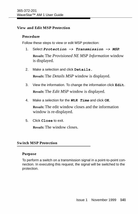
Issue 1 November 1999 141
365-372-201WaveStar™ AM 1 User Guide
View and Edit MSP Protection
Procedure
Follow these steps to view or edit MSP protection:
1. Select Protection -> Transmission -> MSP.
Result: The Provisioned NE MSP Information window is displayed.
2. Make a selection and click Details.
Result: The Details MSP window is displayed.
3. View the information. To change the information click Edit.
Result: The Edit MSP window is displayed.
4. Make a selection for the WtR Time and click OK.
Result: The edit window closes and the information window is re-displayed.
5. Click Close to exit.
Result: The window closes.
Switch MSP Protection
Purpose
To perform a switch on a transmission signal in a point-to-point con-nection. In executing this request, the signal will be switched to the protection.
142 Issue 1 November 1999
365-372-201WaveStar™ AM 1 User Guide
Precautions
A protected switch is always traffic affecting.
Prerequisites
An MSP protection pair should have been provisioned.
Parameters for Switching MSP Protection
Working Section
Displays the group of sections defined as working.
Protection Section
Displays the group of sections defined as protection.
Active Section
Displays which section is carrying traffic.
Switch State
Displays the current switch state of the protection pair.
Selected Pair
Displays the selected sections and indicates the alarm status at the working/protection port. This can be Error Free, Failed or Degraded.
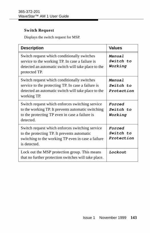
Issue 1 November 1999 143
365-372-201WaveStar™ AM 1 User Guide
Switch Request
Displays the switch request for MSP.
Description Values
Switch request which conditionally switches service to the working TP. In case a failure is detected an automatic switch will take place to the protected TP.
Manual Switch to Working
Switch request which conditionally switches service to the protecting TP. In case a failure is detected an automatic switch will take place to the working TP.
Manual Switch to Protection
Switch request which enforces switching service to the working TP. It prevents automatic switching to the protecting TP even in case a failure is detected.
Forced Switch to Working
Switch request which enforces switching service to the protecting TP. It prevents automatic switching to the working TP even in case a failure is detected.
Forced Switch to Protection
Lock out the MSP protection group. This means that no further protection switches will take place.
Lockout
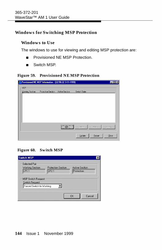
144 Issue 1 November 1999
365-372-201WaveStar™ AM 1 User Guide
Windows for Switching MSP Protection
Windows to Use
The windows to use for viewing and editing MSP protection are:
Provisioned NE MSP Protection.
Switch MSP.
Figure 59. Provisioned NE MSP Protection
Figure 60. Switch MSP
Issue 1 November 1999 145
365-372-201WaveStar™ AM 1 User Guide
Switch MSP Protection
Procedure
Follow these steps to switch MSP protection:
1. Select Protection -> Transmission -> MSP.
Result: The Provisioned NE MSP Information window is displayed.
2. Make a selection and click Switch.
Result: The Switch MSP window is displayed.
3. View the information. To change the switch request click the pull down menu, select a request and click OK.
Result: The previous window is displayed.
4. Click Close to exit.
Result: The window closes.
Add MSP Protection
Purpose
To set protection on a point-to-point connection.
Precautions
If the physical timing reference of the ports to be MSP protected are assigned to a single logical timing references then these ports are no longer available for MSP protection.
146 Issue 1 November 1999
365-372-201WaveStar™ AM 1 User Guide
Prerequisites
MSP pair must be present physically set up on the Near End and Far End Network Elements. In other words, a MSP card inserted and fiber pairs connected on both Network Elements.
Parameters for Adding MSP Protection
Working Section
Displays the group of sections defined as working.
Protection Section
Displays the group of sections defined as protection.
Active Section
Displays which section is carrying traffic.
Switch State
Displays the current switch state of the protection pair.
MSP Pair Selection
Working section port shows the available ports that can be MSP protected. Protection section port will be filled in with the associated protection port once the working section has been selected.
Communication Mode
Communication Mode displays whether the protection is Uni-Dirc-tional or Bi-Dirctional. In the case of failure with Uni-Dirctional mode the receive side switches. In the Bi-Dirctional mode both sides are switched. When the Uni-Dirctional mode is displayed the Far End selection are greyed out.
Issue 1 November 1999 147
365-372-201WaveStar™ AM 1 User Guide
Switch Mode
Switch Mode displays whether the protection is Revertive or Non-Revertive. In the case of failure with Revertive mode the traffic switches to the protected line and switches back when the failure is solved. In the Non-Revertive mode the traffic switches to the pro-tected line and remains even when the failure is solved.
MSP Mode
Displays the MSP protocol to be used. For the WaveStar™ AM 1, the only value possible is ETSI.
WTR Time
WTR (Wait to restore). WTR is the wait to restore time after the fail-ure on the protected unit has cleared. Possible values are 0..60 minutes.
Windows for Adding MSP Protection
Windows to Use
The windows to use for adding MSP protection are:
Provisioned NE MSP Protection.
Add MSP.
148 Issue 1 November 1999
365-372-201WaveStar™ AM 1 User Guide
Figure 61. Provisioned NE MSP Protection
Figure 62. Add MSP
Issue 1 November 1999 149
365-372-201WaveStar™ AM 1 User Guide
Add MSP Protection
Procedure
Follow these steps to Add MSP protection:
1. Select Protection -> Transmission -> MSP.
Result: The Provisioned NE MSP Information window is displayed.
2. Make a selection and click Add.
Result: The Add MSP window is displayed.
3. View the information. To change the information fill in the val-ues with te information above and click OK.
Result: The previous window is displayed.
4. Click Close to exit.
Result: The window closes.

150 Issue 1 November 1999
365-372-201WaveStar™ AM 1 User Guide
Issue 1 November 1999 151
Timing Provisioning
Provision Timing Sources
Purpose
The purpose of provisioning timing sources is to provide timing sources with a defined quality levels (QL), and to assign physical timing references to the logical timing sources used for synchroniz-ion in the network element.
Prerequisites
Before starting these procedures, make sure that a network ele-ment synchronization plan is available.
Precautions
Pay attention to the following items:
An MSP transmission protection pair is considered as a sin-gle timing reference. Thus in the case of MSP on the lines, only one line port is available as a timing reference.
Incorrect settings for worker/protection references and qual-ity level-provisioning can cause a timing loop.
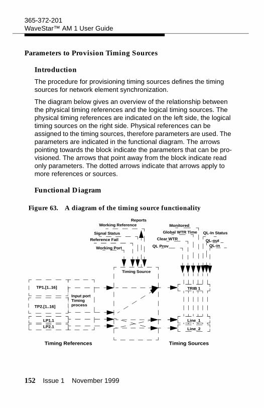
152 Issue 1 November 1999
365-372-201WaveStar™ AM 1 User Guide
Parameters to Provision Timing Sources
Introduction
The procedure for provisioning timing sources defines the timing sources for network element synchronization.
The diagram below gives an overview of the relationship between the physical timing references and the logical timing sources. The physical timing references are indicated on the left side, the logical timing sources on the right side. Physical references can be assigned to the timing sources, therefore parameters are used. The parameters are indicated in the functional diagram. The arrows pointing towards the block indicate the parameters that can be pro-visioned. The arrows that point away from the block indicate read only parameters. The dotted arrows indicate that arrows apply to more references or sources.
Functional Diagram
Figure 63. A diagram of the timing source functionality
Timing Source
Input portTiming process
LP1.1
Timing References Timing Sources
TRIB 1
Line_1
Line_2
Working Port
Reports
QL Prov
Clear WTR
Global WTR Time
Monitored
QL-outQL-in
TP1.[1..16]
TP2.[1..16]
LP2.1
Working Reference
Signal Status
Reference Fail
QL-In Status
Issue 1 November 1999 153
365-372-201WaveStar™ AM 1 User Guide
Clear WTR
The "Clear Wait-to-Restore" command (Clear WTR) resets the wait to restore timer and the signal status will revert to normal.
Monitored
The user can enable or disable the option for monitoring a timing source. If a timing source is monitored, the timing source will for-ward the Reference Fail and Reference Unequipped alarms to the management system when applicable.
Monitored can have the values Yes or No.
QL-in
When the quality level is read from the S1-byte from the timing ref-erences, it is reflected in the QL-in parameter. This parameter can have all of the defined quality level values. See subsection "Timing Quality Levels."
QL-in status
The user can view the status of the incoming quality level (QL-in Status) for each timing source. The possible values are:.
QL-in status Description
Valid The received quality level is in the valid range.
Invalid The received quality level falls outside the valid range or is unstable.
Not Supported The corresponding input port does not provide S1-byte extraction.
Not applicable No reference is assigned to the timing source, or the assigned signal experiences a reference fail.
154 Issue 1 November 1999
365-372-201WaveStar™ AM 1 User Guide
QL-out
The QL-out parameter indicates the actual quality level value of the timing source that is used by the system timing block and the station clock output block. TheQL-out value, is the quality level that enters the system timing and station clock output blocks. When QL-Prov is AUTO, QL-out equals QL-in. When QL-Prov is not AUTO, QL-out equals QL-Prov..
QL-Prov
The quality level of timing references can be provisioned by the user. The provisioned quality level is called QL-Prov. In case of a timing reference without an S1-byte, QL-Prov allows the user to provision a quality level. When a timing reference does have an S1-byte (QL-in can be read by the system), this value can be over-ruled by QL-Prov.
Reference fail
When the incoming signal cannot provide a timing reference, the timing reference is considered to fail. Reference Fail can take the values Yes or No.
Signal status
The signal status is received in the timing sources block and for-warded to the system timing block and the station clock output tim-ing block. The possible values are:
Signal Status Description
Not Connected No reference is assigned to the timing source.
Failed A timing link fail is declared for the assigned timing link.
Issue 1 November 1999 155
365-372-201WaveStar™ AM 1 User Guide
Timing Source
Physical timing references can be assigned to logical timing sources. Once a timing reference is assigned to a timing source, no other reference can be assigned to the same source.
Transmission Protected
Transmission Protected indicates whether the timing ref-erence is MSP-protected for transmission. This is only possible for the WaveStar™ AM1, because this multiplexer supports MSP. The values for Transmission Protected are Yes and No.
Global Wait to Restore Time
In case of a failure the system switches to a valid reference. When the failure is no longer present, the system switches back, after a certain waiting period (the switching is revertive). This waiting period is called the Global Wait-to-Restore Time. It can range from 0 minutes to 60 minutes. The signal status will become Wait to Restore.
The Global Wait to Restore Time setting holds for all the timing in the network element. For the Timing Sources, for the System Tim-ing, and for the Station Clock Output Timing.
Wait to Restore
The assigned reference signal will be available again when the Wait to Restore timer has expired.
Normal The logical timing source is assigned to a valid timing reference.
Signal Status Description
156 Issue 1 November 1999
365-372-201WaveStar™ AM 1 User Guide
Working Port / W Port for WaveStar™ AM1
The worker ports that can be assigned to the timing sources:
Working Reference
Working Reference indicates the actual reference that is used for the selected timing source. Since the WaveStar™ AM 1 does not offer a protection for the timing reference, the Working Ref-erence equals the Working Port as it is provisioned.
Windows to Provision Timing Sources
Windows to Use
The windows to use to provision the timing sources for a network element are:
Provisioned NE Timing Source Information
Detailed Timing Source Information
Assign Timing Reference to Timing Source
Edit Provisioned Timing Source Information
Edit Global Wait to Restore Time
Timing Source Possible Timing References
Line_1 LP1.1, LP2.1
Line_2 LP1.1, LP2.1
TRIB_1 TP1.1 .. TP2.16
Issue 1 November 1999 157
365-372-201WaveStar™ AM 1 User Guide
Figure 64. Provisioned NE Timing Source Information
Figure 65. Detailed Timing Source Information
Figure 66. Assign Timing Reference to Timing Source
158 Issue 1 November 1999
365-372-201WaveStar™ AM 1 User Guide
Figure 67. Edit Provisioned Timing Source Information
Figure 68. Edit Global Wait To Restore Time
Provision Timing Sources
Assign Working Reference to Timing Source
To assign a (working) timing reference to a timing source follow this procedure:
1. Select Provisioning --> Timing --> Timing Sources
Result: The Provisioned NE Timing Source Information window appears.
2. Select a source that must be edited from the list and click Assign.
Result: The Assign Timing Reference to Timing Source window appears.
3. Select a slot (or a ’-’) from the list under Working Reference.
Result: A list of all possible ports (or a ’-’ ) appears for the selected slot.
Issue 1 November 1999 159
365-372-201WaveStar™ AM 1 User Guide
4. Select a port (or a ’-’) from the list for the Working Reference
Result: The Working Reference for the timing source is selected (in case a port is selected) or the Working Reference for the timing source is unassigned (in case ’-’ is selected).
5. Click OK to confirm the current settings.
Result: The Assign Timing Reference to Timing Source window is closed and data is sent to the network element.
Set QL Prov, Monitored, Clear Wait to Restore
To set the quality level for an incoming (SDH) timing reference, clear the Global Wait To Restore Time or set the Monitored state of the timing reference follow this procedure:
1. Select Provisioning --> Timing --> Timing Sources
Result: The Provisioned NE Timing Source Information window appears.
2. Select a source that must be edited from the list and click Edit in the Sources field.
Result: The Edit Provisioned Timing Source Information window appears.
3. Select AUTO or a QL value from the list for QL Provi-sioned.
Result: A value is set for QL provisioned.
160 Issue 1 November 1999
365-372-201WaveStar™ AM 1 User Guide
4. Select Yes or No for Monitored.
Result: The monitoring of the reference of the timing source is set.
5. In case the Signal Status of the timing source is Wait To Restore. and it must be reset, click Clear WTR.
Result: The Signal Status of the timing source changes from Wait to Restore into the actual Signal Status of the timing source.
6. Click OK to confirm the current settings
Result: The Edit Provisioned Timing Source Information window disappears and data is sent to the network element.
7. Click Close.
Result: The Provisioned NE Timing Source Information window disappears.
View the Timing Source Status
To view the status of a timing source follow this procedure:
1. Select Provisioning --> Timing --> Timing Sources
Result: The Provisioned NE Timing Source Information window appears.
2. Select a source to be viewed from the list and click Details.
Result: The Detailed Timing Sources Information window appears.
Issue 1 November 1999 161
365-372-201WaveStar™ AM 1 User Guide
3. Click Update.
Result: The Detailed Timing Sources Information window is filled with the actual parameter settings for the timing source indicated in the Source field.
4. Check the status of the timing source
5. Click Close to close the window.
Result: The Detailed Timing Sources Information window disappears.
6. Click Close.
Result: The Provisioned NE Timing Source Information window disappears.
Edit Global Wait to Restore Time
To change the Global Wait to Restore Time follow this procedure:
1. Select Provisioning --> Timing --> Timing Sources
Result: The Provisioned NE Timing Source Information window appears.
2. Click Edit in the Global Wait To Restore field.
Result: The Edit Global Wait To Restore Time window appears.
3. Set the Global Wait To Restore Time
162 Issue 1 November 1999
365-372-201WaveStar™ AM 1 User Guide
4. Click OK to confirm the current setting.
Result: The Global Wait To Restore timer is set for the timing in the network element, and the Edit Global Wait To Restore Time window disappears.
5. Click Close.
Result: The Provisioned NE Timing Source Information window disappears.
Provision System Timing
Purpose
The purpose of "Provision System Timing" is to lock the network element synchronization and outgoing timing signals to a timing source with the highest quality level.
Prerequisites
Before starting this procedure, make sure that:
The "Provision Timing Source" procedure is completed.
The network element synchronization plan must be avail-able.
Precautions
Pay attention to the following items:
When used, do not forget to clear the lockout condition after maintenance.
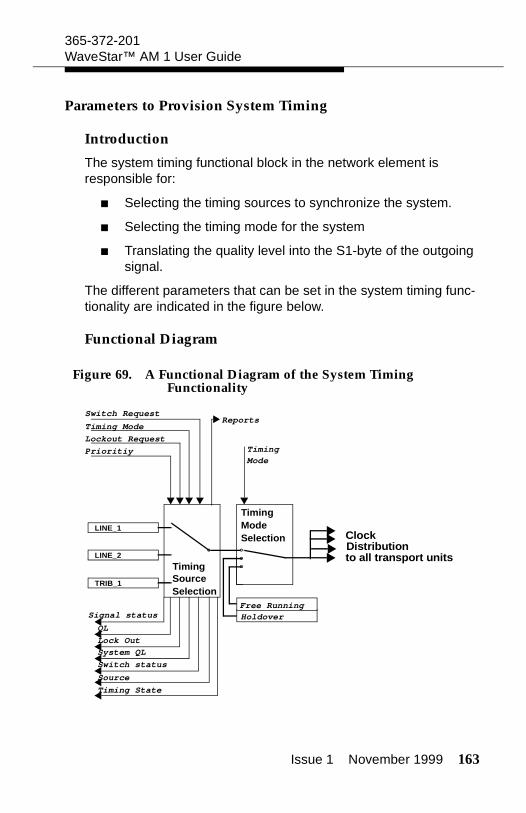
Issue 1 November 1999 163
365-372-201WaveStar™ AM 1 User Guide
Parameters to Provision System Timing
Introduction
The system timing functional block in the network element is responsible for:
Selecting the timing sources to synchronize the system.
Selecting the timing mode for the system
Translating the quality level into the S1-byte of the outgoing signal.
The different parameters that can be set in the system timing func-tionality are indicated in the figure below.
Functional Diagram
Figure 69. A Functional Diagram of the System Timing Functionality
SourceSelection
Timing
Hold over
TimingModeSelection
Prioritiy
Lockout Request
Timing Mode
Switch RequestReports
TimingMode
ClockDistributionto all transport units
Lock Out
System QL
Switch status
Source
Timing State
Free RunningHoldover
LINE_1
LINE_2
TRIB_1
QL
Signal status
164 Issue 1 November 1999
365-372-201WaveStar™ AM 1 User Guide
Active System Timing Source
The Active Timing Source indicates the timing source cur-rently used to synchronize the system, together with the Switch Sta-tus of the source and the latest issued Switch Request.
Lock out
The user can disable a specific timing source that enters the timing source selection without changing the priority settings. If a timing source is locked out, it will not take part in the timing source selec-tion.
Whether a timing source is locked out is indicated by the Lockout parameter. The possible values for the Lockout parameter are: Yes and No.
Lock Out Request
The Lock out state can be changed with the Lock Out Request parameter. This can be set to Yes or No.
The Lock Out Request is for maintenance purposes. A Timing Source, which has a priority value assigned to it, can be temporarily locked out. When the Timing Source is already disabled, a Lock Out Request is rejected. A Lockout Request is set to No automatically when the Timing Source is disabled.
When Priority = Disable the Lock Out Request field is greyed out.
Important! When a timing source is locked out, the network element is in the Abnormal State.
Priority
The priority can be set for each timing source. For a network element with N timing sources provisioned, the priority can have values from 1 to N.
Issue 1 November 1999 165
365-372-201WaveStar™ AM 1 User Guide
The Priority parameter can also have the value Disabled. A disabled timing source will not be taken into account in the Timing Source Selection for the system timing.
Important! Make sure not to provision identical Priority values to multiple timing sources.
QL
The quality level of a timing source, that is used for automatic tim-ing mode selection is indicated in the Provisioned NE System Tim-ing Information window. This QL is identical to the QL-out as described in "Parameters to Provision Timing Sources."
QL Mode
The QL-mode parameter allows to disable or enable the use of the S1-byte in the algoritm to select the active timing reference. The possible values for QL-mode are Enabled and Disabled.
When QL Mode is enabled, the system will choose the timing source with the best quality level. In case of multiple timing sources with all the best quality level, the timing source with the lowest prior-ity value is selected.
Switch request
Switch requests, for WaveStar™ AM1, are shown in the table, together with their description and priority.
Priority Switch Request
Description
No Request This is the default value. The system timing is operating under normal conditions.
166 Issue 1 November 1999
365-372-201WaveStar™ AM 1 User Guide
Switch status
This parameter indicates the latest switch request. The possible values of this parameter are listed in the table below.
1 Clear Switch
Replaces the status by the normal status (in case of a previous switch).
2 Forced Switch
Unconditional switch, issued by the user, even if this is service degrading.
3 Internal protec-tion switch (This is not a switch initiated by the user.)
The active reference has failed, and an internal switch request has been issued.
4 Manual Switch
A conditional switch, which is issued by the user. The switch will not be performed if it is service degrading.
Value Description
No Request No switch request has been issued.
Forced Switch
A forced switch has been made to a timing source as indicated by the user. The forced switch will always be performed by the system except in cases where a lockout command has been issued or if the new timing source has been disabled.
Priority Switch Request
Description
Issue 1 November 1999 167
365-372-201WaveStar™ AM 1 User Guide
Signal status
The signal status is received in the timing sources block and for-warded to the system timing block and the station clock output tim-ing block. The possible values are:
System QL
This parameter shows the quality level value of the timing signal used to clock the system.
Timing Mode
This parameter is used to set one of the three timing modes: Locked, Holdover, and Free Running.
Manual Switch
A manual switch has been made a timing source as indicated by the user. The manual switch will only be performed by the system if a higher priority switch has not taken place and if the new timing source is functioning.
Signal Status Description
Not Connected No reference is assigned to the timing source.
Failed A timing link fail is declared for the assigned timing link.
Wait to Restore
The assigned reference signal will be available again when the Wait to Restore timer has expired.
Normal The logical timing source is assigned to a valid timing reference.
Value Description
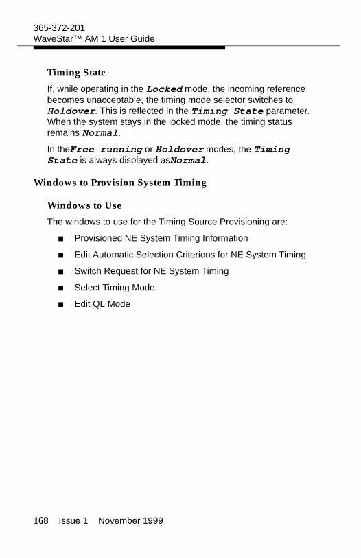
168 Issue 1 November 1999
365-372-201WaveStar™ AM 1 User Guide
Timing State
If, while operating in the Locked mode, the incoming reference becomes unacceptable, the timing mode selector switches to Holdover. This is reflected in the Timing State parameter. When the system stays in the locked mode, the timing status remains Normal.
In theFree running or Holdover modes, the Timing State is always displayed asNormal.
Windows to Provision System Timing
Windows to Use
The windows to use for the Timing Source Provisioning are:
Provisioned NE System Timing Information
Edit Automatic Selection Criterions for NE System Timing
Switch Request for NE System Timing
Select Timing Mode
Edit QL Mode
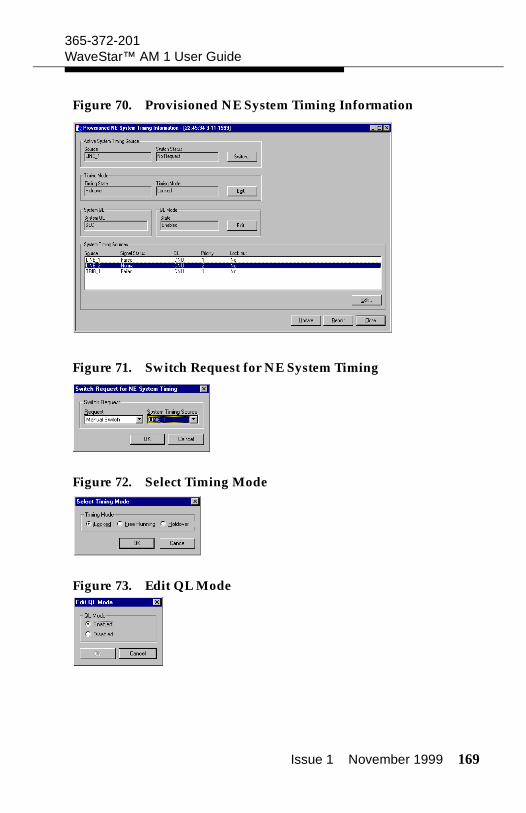
Issue 1 November 1999 169
365-372-201WaveStar™ AM 1 User Guide
Figure 70. Provisioned NE System Timing Information
Figure 71. Switch Request for NE System Timing
Figure 72. Select Timing Mode
Figure 73. Edit QL Mode
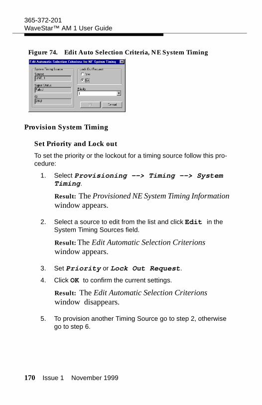
170 Issue 1 November 1999
365-372-201WaveStar™ AM 1 User Guide
Figure 74. Edit Auto Selection Criteria, NE System Timing
Provision System Timing
Set Priority and Lock out
To set the priority or the lockout for a timing source follow this pro-cedure:
1. Select Provisioning --> Timing --> System Timing.
Result: The Provisioned NE System Timing Information window appears.
2. Select a source to edit from the list and click Edit in the System Timing Sources field.
Result: The Edit Automatic Selection Criterions window appears.
3. Set Priority or Lock Out Request.
4. Click OK to confirm the current settings.
Result: The Edit Automatic Selection Criterions window disappears.
5. To provision another Timing Source go to step 2, otherwise go to step 6.
Issue 1 November 1999 171
365-372-201WaveStar™ AM 1 User Guide
6. Click Close.
Result: The Provisioned NE System Timing Information window disappears.
Set Timing Mode and QL Mode
To set the Timing Mode and the QL Mode for a timing source follow this procedure:
1. Select Provisioning --> Timing --> System Timing.
Result: The Provisioned NE System Timing Information window appears.
2. Click Edit in the System QL field.
Result: The Edit QL Mode window appears.
3. Set the QL Mode. to Enabled or Disabled.
4. Click OK to confirm the current settings.
Result: The Edit QL Mode window disappears.
5. Click Edit in the Timing Mode field.
Result: The Edit Timing Mode window appears.
6. Set the Timing Mode to Free Running, Holdover, or Locked.
7. Click OK to confirm the current settings.
Result: The Edit Timing Mode window disappears.
172 Issue 1 November 1999
365-372-201WaveStar™ AM 1 User Guide
8. Click Close
Result: The Provisioned NE System Timing Information window disappears.
Switch Active Timing Source
To switch the timing source that is used as the active timing source follow this procedure:
1. Select Provisioning --> Timing --> System Timing.
Result: The Provisioned NE System Timing Information window appears.
2. Click Switch in the Active Timing Source field.
Result: The Switch Request for NE System Timing window appears.
3. Select a request from the Request list. If a Manual Switch or a Forced Switch is required, select also a timing source to switch to from the System Timing Source list.
4. Click OK to confirm the current settings and send the request to the network element.
Result: Depending on the System state and the request, the switch will be automatically successful or an error message will be displayed. The Switch Request for NE System Timing window disappears.
5. Click Close
Result: The Provisioned NE System Timing Information window disappears.
Issue 1 November 1999 173
365-372-201WaveStar™ AM 1 User Guide
Provision Station Clock Output
Purpose
The purpose of this procedure is to specify the timing source to be used as a reference for the station clock output signals.
Prerequisites
Before starting this procedure, make sure that:
The "Provision Timing Source" procedure is completed
The network timing plan is available
Parameters to Provision Station Clock Output
Introduction
The station clock output functional block in the network element is responsible for selecting the timing source for the station clock out-put.
The different parameters in the station clock output timing block are indicated graphically in the figure below.
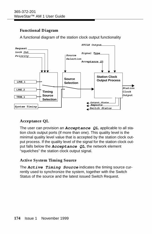
174 Issue 1 November 1999
365-372-201WaveStar™ AM 1 User Guide
Functional Diagram
A functional diagram of the station clock output functionality
Acceptance QL
The user can provision an Acceptance QL, applicable to all sta-tion clock output ports (if more than one). This quality level is the minimal quality level value that is accepted by the station clock out-put process. If the quality level of the signal for the station clock out-put falls below the Acceptance QL, the network element “squelches” the station clock output signal.
Active System Timing Source
The Active Timing Source indicates the timing source cur-rently used to synchronize the system, together with the Switch Status of the source and the latest issued Switch Request.
LINE_1
TRIB_1 SourceSelection
Timing
SourceSelection
Priority
Lock Out
Request
Source
Station ClockOutput Process
SelectionAcceptance QL
STCLK Output
Switch StatusReports
StationClock Output
System Timing
Signal Type
LINE_2
Output State
Issue 1 November 1999 175
365-372-201WaveStar™ AM 1 User Guide
Lock Out Request
The Lock Out state can be changed with the Lock Out Request parameter. This can be set to Yes or No.
The Lock Out Request is for maintenance purposes. A Timing Source, which has a priority value assigned to it, can be temporarily locked out. When the Timing Source is already disabled, a Lock Out Request is rejected. A Lockout Request is set to No automatically when the Timing Source is disabled.
When Priority = Disable the Lock Out Request field is greyed out.
Important! When a timing source is locked out, the network element is in the Abnormal State.
Lock Out
The user can disable a specific timing source that enters the timing source selection without changing the priority settings. If a timing source is locked out, it will not take part in the timing source selec-tion.
Whether a timing source is locked out is indicated by the Lock out parameter. The possible values for the Lock out parameter are: Yes and No.
Output State
The user can view the Output State of the signal generated by the station clock output(s). Possible values are Normal, Dis-abled, and Unacceptable.
Normal: indicates that the output in not disabled and has a quality level above the Acceptance QL
Disabled: indicates that the station clock output is dis-abled
Unacceptable: indicates a quality level below the Acceptance QL, or a signal status is failed.
176 Issue 1 November 1999
365-372-201WaveStar™ AM 1 User Guide
Priority
The priority can be set for each timing source. For a network ele-ment with N timing sources provisioned, the priorities can have val-ues from 1 to N.
The Priority parameter can also have the value Disabled. A disabled timing source will not be taken into account in the Timing Source Selection for the system timing.
Important! Make sure not to provision identical priority values to multiple timing sources.
Signal Type
The Signal Type for the station clock outputs is always 2 MHz.
Source Selection
The station clock output timing can be derived from one of the sys-tem clock processes or from the independent station clock output timing Source Reference Selector. This is provisioned by the user. Two options are available:
System Timing
Independent Station Clock Timing.
STCLK Output
The user can enable or disable the Station Clock Output. If it is disabled it forwards no signal at all and can not be used.
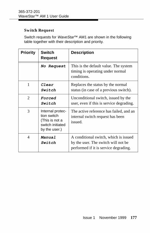
Issue 1 November 1999 177
365-372-201WaveStar™ AM 1 User Guide
Switch Request
Switch requests for WaveStar™ AM1 are shown in the following table together with their description and priority.
Priority Switch Request
Description
No Request This is the default value. The system timing is operating under normal conditions.
1 Clear Switch
Replaces the status by the normal status (in case of a previous switch).
2 Forced Switch
Unconditional switch, issued by the user, even if this is service degrading.
3 Internal protec-tion switch (This is not a switch initiated by the user.)
The active reference has failed, and an internal switch request has been issued.
4 Manual Switch
A conditional switch, which is issued by the user. The switch will not be performed if it is service degrading.
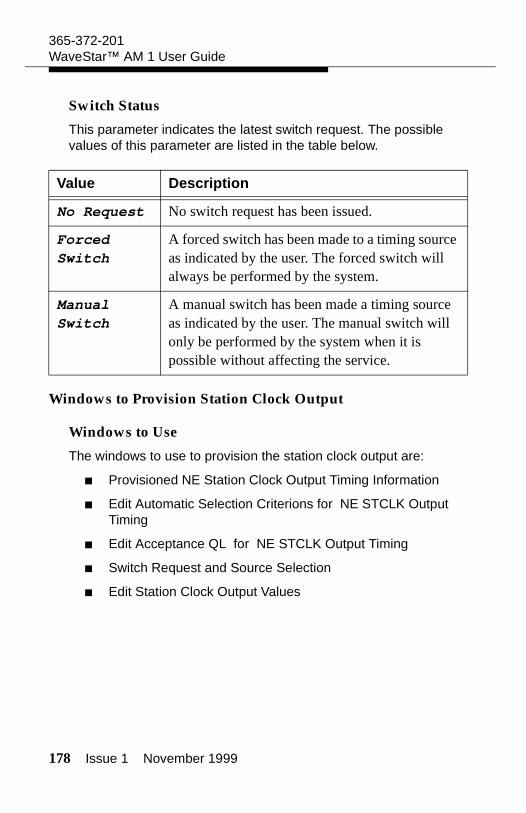
178 Issue 1 November 1999
365-372-201WaveStar™ AM 1 User Guide
Switch Status
This parameter indicates the latest switch request. The possible values of this parameter are listed in the table below.
Windows to Provision Station Clock Output
Windows to Use
The windows to use to provision the station clock output are:
Provisioned NE Station Clock Output Timing Information
Edit Automatic Selection Criterions for NE STCLK Output Timing
Edit Acceptance QL for NE STCLK Output Timing
Switch Request and Source Selection
Edit Station Clock Output Values
Value Description
No Request No switch request has been issued.
Forced Switch
A forced switch has been made to a timing source as indicated by the user. The forced switch will always be performed by the system.
Manual Switch
A manual switch has been made a timing source as indicated by the user. The manual switch will only be performed by the system when it is possible without affecting the service.
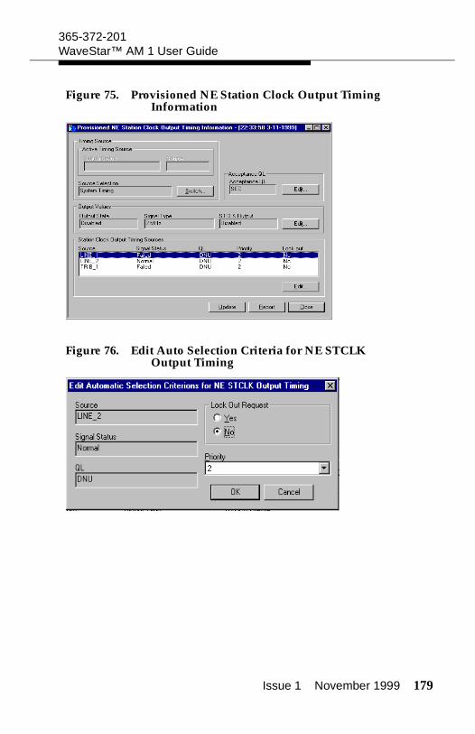
Issue 1 November 1999 179
365-372-201WaveStar™ AM 1 User Guide
Figure 75. Provisioned NE Station Clock Output Timing Information
Figure 76. Edit Auto Selection Criteria for NE STCLK Output Timing
180 Issue 1 November 1999
365-372-201WaveStar™ AM 1 User Guide
Figure 77. Edit Acceptance QL for NE Station Clock Output Timing
Figure 78. Switch Request and Source Selection
Figure 79. Edit Station Clock Output Values
Issue 1 November 1999 181
365-372-201WaveStar™ AM 1 User Guide
Provision Station Clock Output
Set Priority and Lock out
To set the priority or the lockout for a timing source follow this pro-cedure:
1. Select Provisioning --> Timing --> Output Timing.
Result: The Provisioned NE Station Clock Output Timing Information window appears.
2. Select a source to edit from the list and click Edit in the Station Clock Output Timing Sources field.
Result: The Edit Automatic Selection Criterions for Station Clock Output Timing window appears.
3. Set Priority or Lock Out Request.
Important! Setting the priorities has only effect if source selection is set to Independent.
Important! Make sure not to use the same priority value for multiple timing sources, unless explicitly required by the timing plan.
4. Click OK to confirm the current settings.
Result: The Edit Automatic Selection Criterions for Station Clock Output Timing window disappears.
5. To provision another Timing Source go to step 2, otherwise go to step 6.
182 Issue 1 November 1999
365-372-201WaveStar™ AM 1 User Guide
6. Click Close
Result: The Provisioned NE Station Clock Output Timing Information window disappears.
Switch Active Timing Source
To switch the timing source that is used as the active timing source for station clock output timing, follow this procedure:
1. Select Provisioning --> Timing --> System Timing.
Result: The Provisioned NE System Timing Information window appears.
2. Click Switch in the Active Timing Source field.
Result: The Switch Request and NE Source Selection window appears.
3. Select a request from the Request list. If a Manual Switch or a Forced Switch is required, select also a timing source to switch to from the Timing Source list.
4. Click OK to confirm the current settings and send the request to the network element.
Result: Depending on the System state and the request, the switch will be automatically successful or an error message will be displayed. The Switch Request and NE Source Selection disappears.
5. Click Close
Result: The Provisioned NE System Timing Information window disappears.
Issue 1 November 1999 183
365-372-201WaveStar™ AM 1 User Guide
Set Station Clock Output Values
To enable the use of the Station Clock Output, follow this proce-dure:
1. Select Provisioning --> Timing --> Output Timing.
Result: The Provisioned NE Station Clock Output Timing Information window appears.
2. Click Edit in the Output Values field.
Result: The Edit Station Clock Output Values window appears.
3. Select Enabled to enable the use of the station clock out-put, or select Disabled to disable the use of the station clock output.
Important! The WaveStar™ AM 1 supports only the 2 MHz station clock output. Other options are greyed out for WaveStar™ AM 1.
4. Click OK to confirm the current settings and send the request to the network element.
Result: The Edit Station Clock Output Values disappears.
5. Click Close
Result: The Provisioned NE Station Clock Output Timing Information window disappears.
184 Issue 1 November 1999
365-372-201WaveStar™ AM 1 User Guide
Edit Acceptance QL
When the quality level of the signal for the station clock output falls below the Acceptance QL, the station clock output is squelched. To set the Acceptance QL follow this procedure:
1. Select Provisioning --> Timing --> Output Timing.
Result: The Provisioned NE Station Clock Output Timing Information window appears.
2. Click Edit in the Acceptance QL field.
Result: The Edit Acceptance QL for NE STCLK Output Timing window appears.
3. Select the Acceptance QL.
4. Click OK to confirm the current settings and send the setting to the network element.
Result: The Edit Acceptance QL for NE STCLK Output Timing disappears.
5. Click Close
Result: The Provisioned NE Station Clock Output Timing Information window disappears.
Provision Output Port Timing
Purpose
The purpose of output port timing provisioning is to provision the timing properties for the 2 Mbit/s output ports and the station clock output ports.
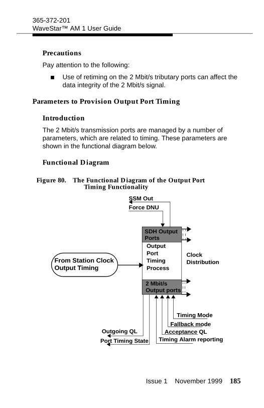
Issue 1 November 1999 185
365-372-201WaveStar™ AM 1 User Guide
Precautions
Pay attention to the following:
Use of retiming on the 2 Mbit/s tributary ports can affect the data integrity of the 2 Mbit/s signal.
Parameters to Provision Output Port Timing
Introduction
The 2 Mbit/s transmission ports are managed by a number of parameters, which are related to timing. These parameters are shown in the functional diagram below.
Functional Diagram
Figure 80. The Functional Diagram of the Output Port Timing Functionality
OutputPortTiming Process
ClockDistribution
SDH OutputPorts
2 Mbit/sOutput ports
Timing Mode
Fallback modeAcceptance QL
Timing Alarm reportingOutgoing QL
Port Timing State
From Station Clock
Force DNU
SSM Out
Output Timing
186 Issue 1 November 1999
365-372-201WaveStar™ AM 1 User Guide
Acceptance QL
For each individual 2 Mbit/s tributary output port in the Re-timed mode, an Acceptance QL can be provisioned.
If the System QL (in case of system timing) or the QL-out (in case of independent timing) falls below the Acceptance QL, the timing will go into the Fallback mode.
Fallback Mode
If a 2 Mbit/s port is operating in the Re-timed mode and if the QL Mode is enabled, the output is automatically switched to the provi-sioned Fallback mode, if the quality level of the system timing drops below the Acceptance QL.
The three Fallback modes are:
Re-timed AIS: A Re-timed AIS is sent out.
Self-timed: The signal is sent out from the port in the Self-timed mode.
None: no Fallback applies.
Force DNU
Force DNU allows to force an S1 byte value: DNU into an outgo-ing signal. The Force DNU option can be switched on by selecting Force. It can be switched off by selecting Do Not Force.
Important! When an outgoing signal is forced to carry DNU, this signal cannot be used for synchronization by another network element.
Outgoing QL
Outgoing QL indicates the quality level that is sent out on a given transmission output port which supports S1-byte quality level information carriage.
Issue 1 November 1999 187
365-372-201WaveStar™ AM 1 User Guide
SSM Out
SSM Out displays the current S1 byte value that is sent out from the selected port.
Timing Mode
The timing mode of each individual 2 Mbit/s tributary output port can be set to the Self-Timed or Re-Timed mode:
In the Self-Timed mode the 2 Mbit/s signal is extracted from the container contents of the VC-12.
In the Re-Timed mode, the timing of the 2 Mbit/s output signal is derived from the network element system timing; the 2 Mbit/s signal is routed through the elastic buffer.
Timing Alarm Reporting
When the Timing State of a 2 Mbit/s tributary output port is Fallback, a defect is declared. The reporting of this Timing Alarm can be Enabled or Disabled for each individual 2 Mbit/s tributary output port. This is done with the Timing Alarm Report parameter.
Timing State
The Port Timing State of each individual 2 Mbit/s tributary output port can be viewed. The Timing State can have two val-ues:
Normal: The port operates as specified in the timing mode
Fallback: The timing mode has fallen back as specified in the Fallback Mode parameter.
188 Issue 1 November 1999
365-372-201WaveStar™ AM 1 User Guide
Windows to Provision Output Port Timing
Windows to Use
The windows to use for the Output Port Timing are:
Port Timing Information
Edit Port Timing Information
2 MBit/s Port Retiming Information.
Edit 2 MBit/s Port Retiming Information.
Figure 81. Port Timing Information
Figure 82. Edit Port Timing Information
Issue 1 November 1999 189
365-372-201WaveStar™ AM 1 User Guide
Figure 83. 2 Mbit/s Port Retiming Information
Figure 84. Edit 2 Mbit/s Port Retiming Information
Provision Output Port Timing
Provision 2 Mbit/s Output Port Timing
To set the parameters for the physical 2 Mbit/s output port follow this procedure:
1. Select Provisioning --> Transport --> Ports.
Result: The Provisioned NE Port Information List window appears.
190 Issue 1 November 1999
365-372-201WaveStar™ AM 1 User Guide
2. Select a 2 Mbit/s port from this list and click Timing.
Result: The 2 Mbit/s Port Retiming Information window appears.
3. Click Edit.
Result: The Edit 2 Mbit/s Port Retiming Information window appears.
4. Set the Timing Mode. In case of a re-timed value, set also the Fallback Mode and the Acceptance QL values.
5. Set the Timing Alarm Reporting values.
6. Click OK to confirm the current settings.
Result: Depending on the chosen values a warning message can appear. The Edit 2 Mbit/s Port Retiming Information window disappears.
7. Click OK.
Result: The 2 Mbit/s Port Retiming Information window disappears.
8. To set another 2 Mbit/s port go to step 2, else go to step 9.
9. Click Close.
Result: The Provisioned NE Port Information List window disappears.
Issue 1 November 1999 191
365-372-201WaveStar™ AM 1 User Guide
Provision STM-1 Output Port Timing
To set the parameters for the physical STM-1 output ports follow this procedure:
1. Select Provisioning --> Transport --> Ports.
Result: The Provisioned NE Port Information List window appears.
2. Select an STM-N port from this list and click Timing.
Result: The Port Timing Information window appears.
3. Click Edit.
Result: The Edit Port Timing Information window appears.
4. Set the Force DNU value.
5. Click OK to confirm the current settings.
Result: Depending on the chosen values a warning message can appear. The Edit Port Timing Information window disappears.
6. Click OK.
Result: The Port Timing Information window disappears.
7. To set another STM-1 port go to step 2, else go to step 8.
8. Click Close.
Result: The Provisioned NE Port Information List window disappears.

192 Issue 1 November 1999
365-372-201WaveStar™ AM 1 User Guide