Embed Size (px)
Citation preview

Waynetown Water System Improvements
Division “A”-New Water Treatment Plant
Town of Waynetown, IN
Submittal Review Sheet
Attached is the submittal for the Adjustable Frequency Drives for High Service Pumps for the
Waynetown Water Systems Improvements Project for your review and approval. Thieneman
Construction has reviewed the submittal information and added the following notes for your review,
approval, and consideration:
Items for Commonwealth Engineers:
1. Adjustable Frequency Drives for High Service Pumps only
Items for Supplier:
1. Supply materials as requested by TCI in conformance with the project schedule.
If you have any questions on this submittal information, please contact Travis Smith at (317) 750-9622. Thieneman
Construction requests your review, approval, and return of one (1) copy of the approved submittals.
Project Name: Waynetown Water Systems Improvements
Contractor: Thieneman Construction, Inc.
Subcontractor / Supplier: S&K Equipment
Submittal Number: DS-23-06
Submittal Specification Section: DS-23
Item Description: 262923 – Adjustable Frequency Drives for High Service
Pumps
Quantity of Submittals: 1 – Electronic
Comments: See Above
Quantity of Approved Submittals to be Returned: 1 – Electronic
Signature: Travis Smith
CONTRACTOR’S CERTIFICATION Submittal material has been reviewed for compliance with specifications and drawings. Required field measurements have been verified. The work shown on this submittal has been coordinated with other submittals affected by this work. All data has been checked by the Contractor and any variations from the specifications or drawings have been noted. The work described on the submittal material is recommended by the Contractor, and the guarantee in the specifications will apply:
Contractor: Thieneman Construction
Approved: Travis Smith
Date: 10/13/16

§§§§§§§§§§§§§§§§§§§§§§§§§§§§§§§§§§§§§§§§§§§§§§§§§§§§§§§§§§§§§§§§§§§§§§§§§§§§§§§§§
Frame Mounted End Suction Centrifugal Pumps Water Treatment Plant – High Service Pumps
Waynetown, Indiana
Submittal Documentation
Contractor: Engineer: Thieneman Construction, Inc. Commonwealth Engineers, Inc.
Westfield, Indiana Indianapolis, Indiana
S & K Equipment - Job #643-16
Respectfully Submitted by:
S & K Equipment Company, Inc. 1243 Bayou Street
P. O. Box 342 Vincennes, IN 47591
Phone: (812) 886-0245 Fax: (812) 886-1211
Email: [email protected]
§§§§§§§§§§§§§§§§§§§§§§§§§§§§§§§§§§§§§§§§§§§§§§§§§§§§§§§§§§§§§§§§§§§§§§§§§§§§§§§§§

Frame Mounted End Suction Centrifugal Pumps High Service Pumps Waynetown, Indiana
S & K Equipment Project #643-16
We propose to furnish the following equipment for the High Service Pump Station at the Waynetown Water Treatment Plant. To the best of our knowledge we either meet or exceed the requirements. However, if questions arise or you require additional information, please do not hesitate to contact us.
Two {2} – Peerless, Model F815AM, frame mounted, end suction centrifugal booster pumps, each rated for 215 GPM @ 165’ TDH, with: cast iron construction; nickel aluminum bronze impeller; mechanical seal; fabricated steel base with grout hole; TB Woods, Sureflex 7SJES, flexible coupling; ANSI B15.1 Shell Type coupling guard; 2” NPT suction and 1.5” NPT discharge connections; and driven by a 15 HP, 3500 RPM, 3/460 volt, Premium Efficient, Inverter Duty motor with AEGIS ground ring. Factory certified pump testing is included. The specified spare parts are included.
Two {2} WEG, Model CFW110024T4ON1Z, Variable Frequency Drives, properly sized for the above motors, each in a stainless steel wall mount enclosure. Each includes: disconnect switch; 120 volt control transformer; cooling fan; and provisions to communicate: Start; Stop; Run; Fail; and Speed signals to the FCP (FCP by others).
S & K EQUIPMENT COMPANY, Inc. … When Quality Counts …
P. O. Box 342 1243 Bayou Street
Vincennes, IN 47591 Ph (812) 886-0245 Fx (812) 886-1211

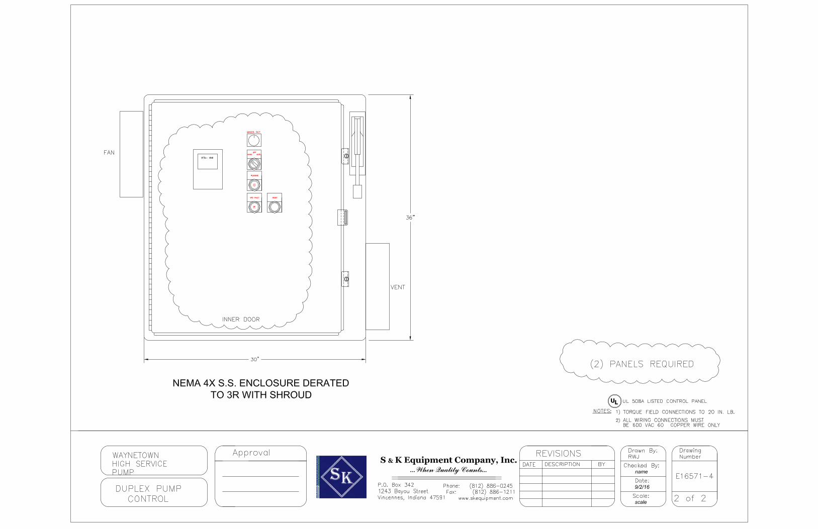
DATA SHEET
HIGH SERVICE PUMP CONTROL PANEL DATE: September 8, 2016
PROJECT NAME: WAYNETOWN PROJECT NO: 16-571
HORSEPOWER: 15 VOLTAGE: 460 PHASE: 3 TYPE: DUPLEX
1
QTY ITEM MFG MODEL # ENCLOSURE & ACCESSORIES
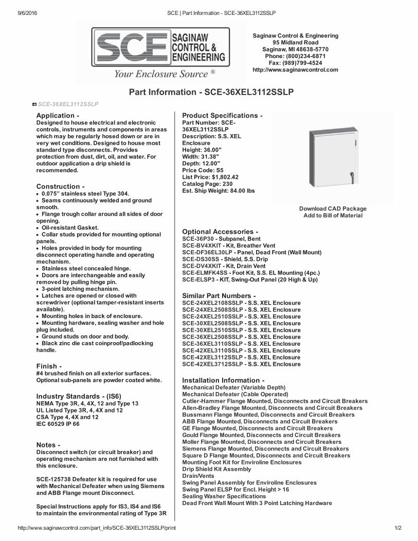
1 ENCLOSURE SAGINAW SCE36XEL3112SSLP 1 SUBPANEL HOFFMAN A36P30 1 INNER DOOR QCI FAB1 FAN KIT RITTAL 3241.110 1 SS SHROUD KIT RITTAL 3240.080 1 FILTER RITTAL 3240.200
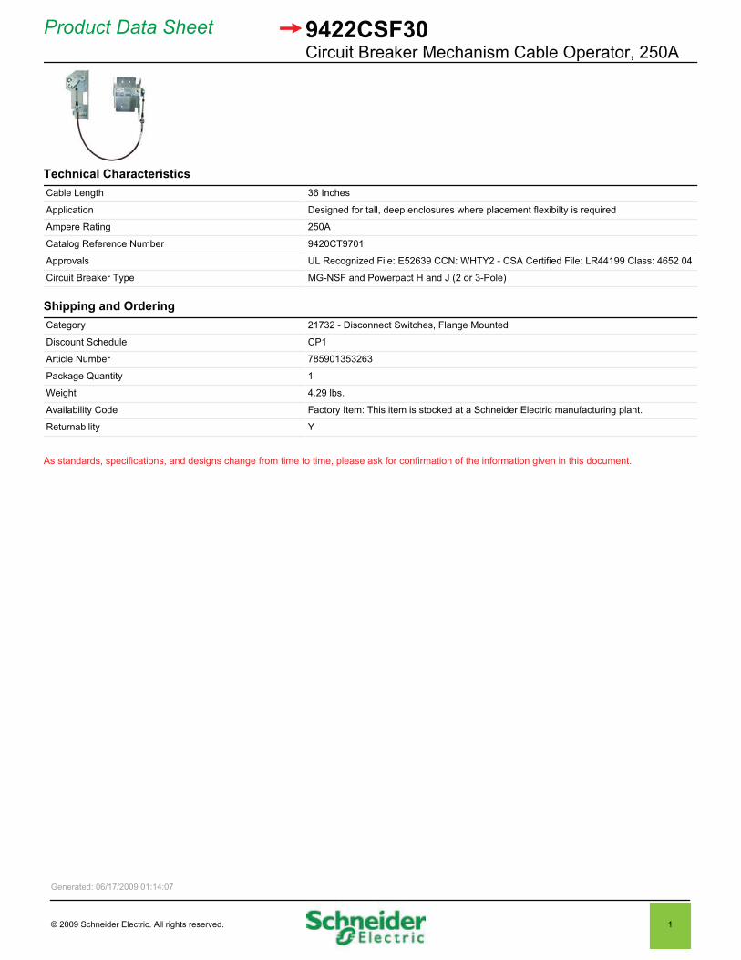
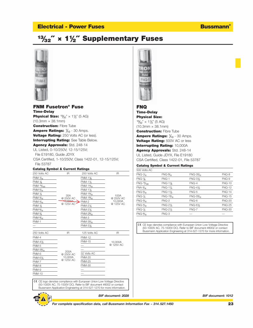
MAIN POWER COMPONENTS 1 MAIN BREAKER SQUARE D HLL36040 1 INTERLOCKING HANDLE SQUARE D 9422CSF30 1 HANDLE SQUARE D 9422A2 1 TRANSFORMER SQUARE D 9070TF150D1 2 PRIMARY FUSES BUSSMAN FNQ-R0.6 1 SECONDARY FUSE BUSSMAN FNM2
CONTROL COMPONENTS 1 THERMOSTAT GENESIS 01141.9-00 2 CONTROL BREAKERS SQUARE D QOU110
SWITCHES & INDICATORS 1 HOA SWITCH SQUARE D XB5AD33 1 SPEED POT DIAL SQUARE D ZB5AD922 1 SPEED POT RS 10 OHM 2 CONTACT BLOCKS (N.O.) SQUARE D ZB5AZ101 1 GREEN LIGHTS SQUARE D XB5AVG3 1 RED LIGHTS SQUARE D XB5AVG4 1 BLACK PUSH BUTTON SQUARE D XB5AA21
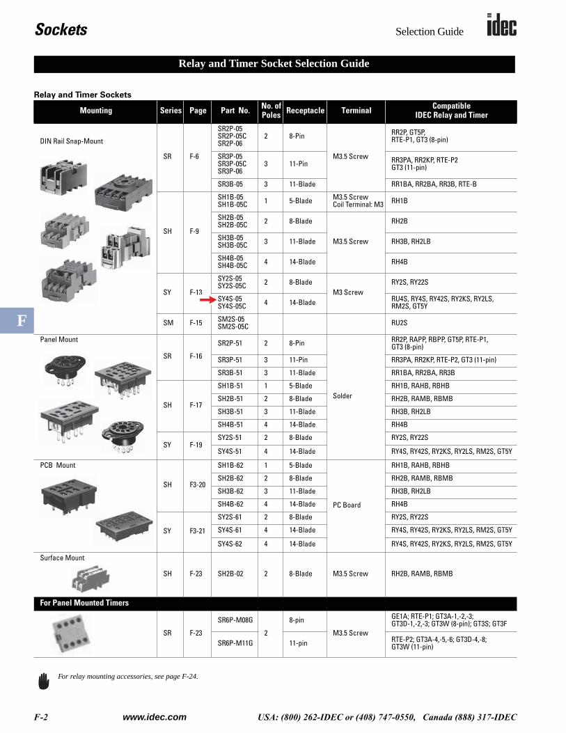
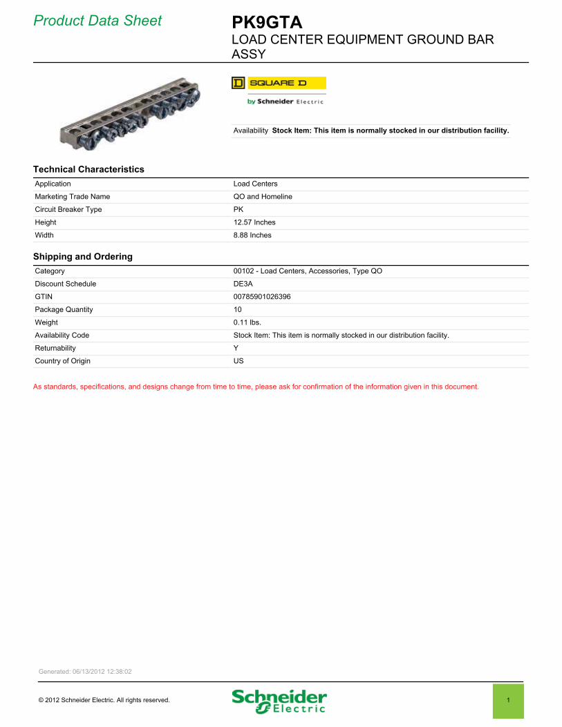
RELAYS & MISC COMPONENTS2 CONTROL RELAYS 120V SQUARE D RXM4AB2F7 2 RELAY BASES IDEC SY4S-05 1 GROUND BAR SQUARE D PK9GTA
10 TERMINAL BLOCKS SQUARE D 9080-GR6 LABELS
1 TYPE 4 QCI PUMPHAND OFF AUTO
1 TYPE 4 QCI VFD FAULT 1 TYPE 4 QCI RUNNING 1 TYPE 4 QCI RESET 1 TYPE CUSTOM QCI S&K 643-16
SUPPLIED COMPONENTS1 VFD WEG CFW110024T4ON1Z 1 KEYPAD KIT 1 CABLE


382 Metric measurements for are exact, imperial measurements are rounded
Air Displacement: 106 - 147 cfm (180 - 250 m3/h)Part No. (Filter Fan and Filter Unit) 3240.100 3240.110 3240.124 3241.100 3241.110 3241.124
Part No. (Filter Fan and Filter Unit - EMC) 3240.600 3240.610 – 3241.600 3241.610 –
230, 50/60 115, 50/60 24 (DC) 230, 50/60 115, 50/60 24 (DC)
Dimensions inches (mm)
B1/H1 10 x 10 (255 x 255)
B2/H2 9 x 9 (224 x 224)
T1 0.98 (25)
Max. installation depth inches (mm) T2 4.21 (107)
Air throughput, unimpeded air flow 106/94 cfm (180/160 m3/h)106 cfm (180
m3/h)135/147 cfm (230/250 m3/h)
135 cfm (230
m3/h)
Air throughput with outlet filter
including standard filter mat
1 x 3240.200: 81/71 cfm (138/121 m3/h)
2 x 3240.200: 97/82 cfm (165/140 m3/h)
1 x 3243.200: 97/82 cfm (165/140 m3/h)
1 x 3240.200: 108/120 cfm (183/205 m3/h)
2 x 3240.200: 119/135 cfm (203/230 m3/h)
1 x 3243.200: 119/135 cfm (203/230 m3/h)
Diagonal fan Self-starting shaded pole motor DC motor Self-starting shaded pole motor DC motor
Rated current 0.21 A/0.19 A 0.42 A/0.38 A 0.43 A 0.26 A/0.24 A 0.52 A/0.48 A 0.78 A
Power consumption 35 W/34 W 11 W 40 W/42 W 19 W
Pre-fuse 2 A 4 A 2 A 4 A 2 A
Noise level 51/46 dB (A) 51 dB (A) 54/56 dB (A) 54 dB (A)
Operating temperature range F° (C°) -22 to 131° F (–30 to +55° C)
Storage temperature range F° (C°) -22 to 158° F (–30 to +70° C)
Color RAL 7035
Part No. outlet filter 3240.200
Accessories PU Page
Filter mats 5 3172.100 483
Filter mats – EMC 5 3240.066 483
Fine filter mats 5 3182.100 484
Hose-proof hood - Type 304 stainless steel 1 3240.0801) 487
Hose-proof hood - RAL 7035 1 3240.0852) 487
Blanking cover 1 3240.020 485
Thermostat 1 3110.000 476
Digital temperature display 1 3114.200 475
Hygrostat 1 3118.000 476
Speed control 1 3120.200 477
1) UL Type 4X 2) UL Type 3R/4
Special voltages and colors available on request. We reserve the right to make technical modifications.
TopTherm filter fan/exhaust
Rittal Catalog 33/Climate control

Accessories for fan-and-filter units
7Rittal – TopTherm fan-and-filter unit
Hose-proof hoodFor fan-and-filter units/outlet filters. When the hose-proof hood is mounted above the fan-and-filter unit and outlet filter in conjunction with a fine filter mat, a protection category of IP 56 to EN 60 529 is achieved.
Material:Stainless steel, silicone
Protection category:In conjunction with the fan-and-filter units/outlet filters, NEMA 3R + 12 is met.
For fan-and-filter unitDimensions
mmModel No.
SK
SK 3237. . . . 150 x 230 x 40 3237.080
SK 3238. . . . 176 x 245 x 55 3238.080
SK 3239. . . . 233 x 330 x 55 3239.080
SK 3240. . . ./SK 3241. . . . 282 x 390 x 85 3240.080
SK 3243. . . ./SK 3244. . . .SK 3245. . . .
350 x 480 x 110 3243.080
Blanking coverIf existing mounting cut-outs for fan-and-filter units/outlet filters need to be closed to achieve a higher protection category, the filter mat of the fan-and-filter unit/outlet filter can simply be re-placed with a blanking cover; welding or other mechanical modification of the enclosure is not necessary.
Material:Plastic
Protection category:IP 55
For fan-and-filter unitModel No.
SK
SK 3237. . . . 3237.020
SK 3238. . . . 3238.020
SK 3239. . . . 3239.020
SK 3240. . . ./SK 3241. . . . 3240.020
SK 3243. . . ./SK 3244. . . .SK 3245. . . .
3243.020
Spare filter matsMade of chopped-fibre mat with a progressive structure. Temperature-resistant to 100°C, self-extinguishing category F1 to DIN 53 438.Dust-laden air side: Open structure.Clean air side: Closed structure.Reliable filtering of virtually all types of dust from a particle size of 10 μm.
Material:Chemical fibre
For fan-and-filter unitFilter class
to DIN EN 779Model No.
SK
3237. . . . G2 3321.700
3238. . . . G2 3322.700
3239. . . . G3 3171.100
3240. . . ./3241. . . . G3 3172.100
3243. . . ./3244. . . . G3 3173.100
Fine filter matsMade of chopped-fibre mat with a progressive structure. Temperature-resistant to 100°C, self-extinguishing category F1 to DIN 53 438.Dust-laden air side: Open structure.Clean air side: Closed structure.Reliable filtering of virtually all types of dust from a particle size of 10 μm.
Material:Chemical fibre
For fan-and-filter unitFilter class
to DIN EN 779Model No.
SK
3238. . . . F5 3238.055
3239. . . . F5 3181.100
3240. . . ./3241. . . . F5 3182.100
3243. . . ./3244. . . . F5 3183.100


����������� ��� ��������������������� ��������������������������
��������� �� �!���"#$
�%���������& ��� ������������������������ ������������������������������������� !���"
�������'�� ()�*����
����������� $��'�+�,���������+�����������-�����������,�.�����&�����/���+
�����0����' ����
������'�0,����1���� 2���3 4��
�����%��� "��0��'��5+�6��7�8��)( ���17�9:3;��<��#������,�+�6��7��022� ������7�2)����2
�������������3&� =<1#6���+���-������:���+�>�?�����(<���@
�����������������������
���'��& ��4(��<�$���������#-�������6���'� ����+
$��������#��+�� ���
�������1���� 4A� ��(�(�)(
�����'�B������& �
9�'�� 2!� ����!
�%���������&���+ 6�����&�*��7�3����������������+������#����+��8�����������,�������'������!
0����������& ;
���!!�� ����#������ �
�������+��+�������,������������+�+��'�������'�,�������������������������,������,����������,������,���������'�%����������+������!
=����+7��)C�4C��� ���7�27�4
D���� �#����+��8������!�������'�������%+!
�
�

����������� ��� ����$�$���������#-�����:��+�� ��������E��
��������� ��4�!���"#$
�%���������& �� ����������������������� �������� �������� ���������%��� ���������"
�����%��� "��0��'��5+�6��7�8��)( ���1�9:3;��<��#������,�+�6��7��022� ������7�2)����2
3&� 3
������'�0,����1���� 2���3 4��
6���"��9��� 18 ��2C2F�?������������@
:��+��3&� )�*���
�����������������������
���'��& ��4(��<�$���������#-�������6���'� ����+
$��������#��+�� ���
�������1���� 4A� ��4( A�4
�����'�B������& �
9�'�� �!A2����!
�%���������&���+ #�����*��7�3������������������&������+��������+������������,������&!
0����������& ;
���!!�� ����#������ �
�������+��+�������,������������+�+��'�������'�,�������������������������,������,����������,������,���������'�%����������+������!
=����+7��)C�4C��� ���72�72�
D���� �#����+��8������!�������'�������%+!
�
�

roduct ata heetTRA SF R R TR 1 0VA2 0/ 0V 120V
ist rice 21 .00 SD
Availa ility
Application Develop to help customers comply ith Standard 0 and 0
Specifications 0. 1 1. 0 nch lass rimary Fuse olders
Terminal Type Scre lamp
Type TF
ountin Type anel
Fuse lock Top ounted
Approvals isted File um er 612 SA ertified File um er R 0 uide 1 0 arked
hase 1 hase
nclosure Type pen
rimary 2 0 0V or 2 0 60V or 220 0V
Ratin 1 0VA
nsulation Temperature 10 De rees
Secondary 120V or 11 V or 110V
Temperature Rise De rees
indin aterial opper
ei ht . nches
idth . nches
Depth . nches
ate ory 16202 Transformers ndustrial ontrol 0 200 va Type TF
Discount Schedule
T 00 01 0
acka e uantity 1
ei ht 6. l s.
Availa ility ode Stock tem This item is normally stocked in our distri ution facility.
Returna ility
ountry of ri in
As standards specifications and desi ns chan e from time to time please ask for confirmation of the information iven in this document.
enerated 01/ 0/201 1
201 Schneider lectric. All ri hts reserved.
1

Bussmann®
20 For complete specification data, call Bussmann Information Fax ~ 314.527.1450
Electrical - Power Fuses
BIF document: 1014 BIF document: 1015
Class CC Rejection-Type Fuses
FNQ-RTime-Delay, Rejection TypeBranch Circuit FuseClass CC
Physical Size: ⁄‹Ω£™∑ ≈ 1⁄Ω™∑ (10.3mm ≈ 38.1mm)Construction: Melamine TubeAmpere Ratings: ⁄Ω¢-30 Amps.Voltage Rating: 600V AC or lessInterrupting Rating: 200,000A RMS Sym. Agency Approvals: Std. 248-4, Class CCUL Listed, Guide JDDZ, File E4273CSA Certified, Class 1422-01, File 53787
Catalog Symbol & Current Ratings600 Volts AC
FNQ-R-⁄Ω¢ FNQ-R-1⁄Ω™ FNQ-R-6
FNQ-R-‹Ω¡º FNQ-R-1flΩ¡º FNQ-R-6⁄Ω¢
FNQ-R-›Ω¡º FNQ-R-1°Ω¡º FNQ-R-7⁄Ω™
FNQ-R-⁄Ω™ FNQ-R-2 FNQ-R-8
FNQ-R-flΩ¡º FNQ-R-2⁄Ω¢ FNQ-R-9
FNQ-R-‹Ω¢ FNQ-R-2⁄Ω™ FNQ-R-10
FNQ-R-°Ω¡º FQN-R-2°Ω¡º FNQ-R-12
FNQ-R-1 FNQ-R-3 FNQ-R-15
FNQ-R-1⁄Ω• FNQ-R-3¤Ω¡º FNQ-R-20
FNQ-R-1⁄Ω¢ FNQ-R-3⁄Ω™ FNQ-R-25
FNQ-R-1‹Ω¡º FNQ-R-4 FNQ-R-30
FNQ-R-1›Ω¡º FNQ-R-5
Time-Current and Current Limitation Curves on page 217.
KTK-R Limitron® FuseFast Acting; Branch Circuit Fuse
Class CC - Rejection FeaturePhysical Size: ⁄‹Ω£™∑ ≈ 1⁄Ω™∑ (10.3mm ≈ 38.1mm)Construction: Melamine TubeAmpere Ratings: ⁄Ω¡º-30 Amps.Voltage Rating: 600 Volts AC (or less). Interrupting Rating: 200,000A Agency Approvals: Std. 248-4, Class CCUL Listed, Guide JDDZ, File E4273 CSA Certified, File 53787, Class 1422-02
Catalog Symbol & Current Ratings600 Volts AC
KTK-R-⁄Ω¡º KTK-R-1 KTK-R-7
KTK-R-⁄Ω• KTK-R-1⁄Ω™ KTK-R-8
KTK-R-¤Ω¡º KTK-R-2 KTK-R-9
KTK-R-⁄Ω¢ KTK-R-2⁄Ω™ KTK-R-10
KTK-R-‹Ω¡º KTK-R-3 KTK-R-12
KTK-R-›Ω¡º KTK-R-3⁄Ω™ KTK-R-15
KTK-R-⁄Ω™ KTK-R-4 KTK-R-20
KTK-R-flꭧ KTK-R-5 KTK-R-25
KTK-R-‹Ω¢ KTK-R-6 KTK-R-30
Time-Current and Current Limitation Curves on page 218.
Recommended Fuseblocks for Class CC FusesScrew Pressure
No. of Screw Pressure Box Quick- Quick-Poles Terminal Plate Terminal Connect Connect
1 BC6031S BC6031P BC6031B BC6031SQ BC6031PQ
2 BC6032S BC6032P BC6032B BC6032SQ BC6032PQ
3 BC6033S BC6033P BC6033B BC6033SQ BC6033PQ
CE logo denotes compliance with European Union Low Voltage Directive(50-1000V AC, 75-1500V DC). Refer to BIF document #8002 or contactBussmann Application Engineering at 314-527-1270 for more information.
CE logo denotes compliance with European Union Low Voltage Directive(50-1000V AC, 75-1500V DC). Refer to BIF document #8002 or contactBussmann Application Engineering at 314-527-1270 for more information.
Bussmann®
23For complete specification data, call Bussmann Information Fax ~ 314.527.1450
Electrical - Power Fuses
BIF document: 2028 BIF document: 1012
⁄‹Ω£™∑ ≈ 1⁄Ω™∑ Supplementary Fuses
250 Volts AC IR 125 Volts AC IR
FNQTime-Delay Physical Size: ⁄‹Ω£™∑ ≈ 1⁄Ω™∑ (5 AG)(10.3mm ≈ 38.1mm)Construction: Fibre TubeAmpere Ratings: ⁄Ω¡º - 30 Amps.Voltage Rating: 500V AC or lessInterrupting Rating: 10,000AAgency Approvals: Std. 248-14UL Listed, Guide JDYX, File E19180CSA Certified, Class 1422-01, File 53787
Catalog Symbol & Current Ratings500 Volts AC
FNQ-⁄Ω¡º FNQ-°Ω¡º FNQ-3¤Ω¡º FNQ-8
FNQ-⁄Ω• FNQ-1 FNQ-3⁄Ω™ FNQ-9
FNQ-⁄fiΩ¡ºº FNQ-1⁄Ω• FNQ-4 FNQ-10
FNA-‹Ω¡§ FNQ-1⁄Ω¢ FNQ-4⁄Ω™ FNQ-12
FNQ-¤Ω¡º FNQ-1⁄Ω™ FNQ-5 FNQ-14
FNQ-⁄Ω¢ FNQ-1flΩ¡º FNQ-5flΩ¡º FNQ-15
FNQ-‹Ω¡º FNQ-2 FNQ-6 FNQ-20
FNQ-›Ω¡º FNQ-2⁄Ω¢ FNQ-6⁄Ω¢ FNQ-25
FNQ-⁄Ω™ FNQ-2⁄Ω™ FNQ-7 FNQ-30
FNQ-flΩ¡º FNQ-3 — —
FNM Fusetron® FuseTime-DelayPhysical Size: ⁄‹Ω£™∑ ≈ 1⁄Ω™∑ (5 AG)(10.3mm ≈ 38.1mm)Construction: Fibre TubeAmpere Ratings: ⁄Ω¡º - 30 Amps.Voltage Rating: 250 Volts AC (or less). Interrupting Rating: See Table Below.Agency Approvals: Std. 248-14UL Listed, 0-10/250V; 12-15/125V; File E19180, Guide JDYX
CSA Certified, 1-10/250V; Class 1422-01, 12-15/125V; File 53787
Catalog Symbol & Current Ratings250 Volts AC IR 250 Volts AC IR
FNM-⁄Ω¡ºFNM-⁄Ω•FNM-⁄fiΩ¡ººFNM-¤Ω¡ºFNM-⁄Ω¢
35AFNM-‹Ω¡º @ 250V ACFNM-›Ω¡º 10,000A
FNM-⁄Ω™@ 125V AC
FNM-flΩ¡ºFNM-‹Ω¢FNM-°Ω¡ºFNM-1—
FNM-1⁄Ω•
FNM-1⁄Ω¢
FNM-1›Ω¡º
FNM-1⁄Ω™
FNM-1flꭧ100A
FNM-1°Ω¡º @ 250V ACFNM-2 10,000A
FNM-2⁄Ω¢@ 125V AC
FNM-2⁄Ω™
FNM-2°Ω¡º
FNM-3FNM-3¤Ω¡º
FNM-3⁄Ω™
FNM-4
FNM-4⁄Ω™
FNM-5FNM-5flꭧ
200AFNM-6 @ 250V ACFNM-6⁄Ω¢ 10,000A
FNM-7@ 125V AC
FNM-8FNM-9FNM-10
FNM-12FNM-15 10,000A— @ 125V AC
—32 Volts ACFNM-20FNM-25FNM-30——
CE logo denotes compliance with European Union Low Voltage Directive(50-1000V AC, 75-1500V DC). Refer to BIF document #8002 or contactBussmann Application Engineering at 314-527-1270 for more information.
CE logo denotes compliance with European Union Low Voltage Directive(50-1000V AC, 75-1500V DC). Refer to BIF document #8002 or contactBussmann Application Engineering at 314-527-1270 for more information.

Technical Data
Regu
latin
g
KT 011 Small Thermostat
|
KT01
1/11
-12/
US
Specifications are subject to change without notice. Suitability of this product for its intended use and any associated risks must be determined by the end customer/ buyer in its final application.
STEGO, Inc. · 1395 South Marietta Parkway · Building 800 · Marietta, GA 30067 · Tel: (770) 984-0858 · Fax: (770) 984-0615Toll free: 1-888-783-4611 (US & Canada only) · www.stegousa.com
Compact design
Wide adjustment range
Color coded temperature dials
DIN rail mountable
Thermostat NC (normally closed)Thermostat opens on temperature rise - for regulating heaters or for switching signal devices.Comes with red temperature dial.
Thermostat NO (normally open)Thermostat closes on temperature rise - for regulating filter fans and heat exchangers or forswitching signal devices. Comes with blue temperature dial.
Switching difference 12.6 °F ± 7 °F tolerance (7 K ± 4 K)
Sensor element thermostatic bimetal
Contact type snap-action contact
Service life > 100,000 cycles
Max. switching capacity 15 A resistive / 2 A inductive @ AC 120 V
10 A resistive / 2 A inductive @ AC 250 V
DC 30 W
Max. inrush current AC 16 A for 10 sec.
Connection 2-pole terminal, clamping torque 0.5 Nm max.:
solid wire - AWG 14 max. (2.5 mm²)
stranded wire (with wire end ferrule) - AWG 16 (1.5 mm²)
Housing plastic, UL 94V-0, light grey
Mounting clip for 35 mm DIN rail, EN 60715
(or for Exhaust Filter EF 118 Series)
Mounting position vertical
Operating / Storage temperature -49 to +176 °F (-45 to +80 °C)
Dimensions 2.4 x 1.3 x 1.7” (60 x 33 x 43 mm)
Weight approx. 1.4 oz. (40 g)
Protection type IP20
Setting range Part No. (NC) Part No. (NO) Approvals+32 to +140 °F 01140.9-00 01141.9-00 UL File No. E164102, CSA, VDE
0 to +60 °C 01146.9-00 01147.9-00 UL File No. E164102, CSA, VDE-10 to +50 °C 01142.0-00 N/A UL File No. E164102, CSA, VDE+10 to +70 °C N/A 01149.9-00 UL File No. E164102, CSA, VDE-15 to +45 °C 01157.0-00 01156.0-00 UL File No. E164102, CSA, VDE+20 to +80 °C 01159.0-00 01158.0-00 UL File No. E164102, CSA, VDE
1.3” (33 mm)
1.7
”(4
3m
m)
2.4
”(6
0m
m)
NC (red) NO (blue) Wiring examples
KT 011 Thermostat Heater KT 011 Thermostat e.g. Fan KT 011 Thermostat e.g. Signal Device

roduct ata heetiniature ircuit reaker Standard 10A
1 ole 120/2 0VA A R Rated
ist rice 0.20 SD
Availa ility
Ampere Ratin 10A
Approvals isted SA 22.2 .1 ertified Rated 60 2
ircuit reaker Type Standard
For se ith anels and nclosures
A R Rated es
arketin Trade ame
Volta e Ratin 120/2 0VA
ountin Type Flush Surface or D Rail mm
um er of oles 1 ole
Short ircuit urrent Ratin kA 2 VA 10kA 120/2 0VA
Terminal Type ine o u oad o u
Type
ire Si e 1 2 A Al/ u
Depth 2. nches
ei ht .0 nches
idth 0. nches
ate ory 00 00 ircuit reakers 1 ole 10 100 Amp 2 ole 10 12 Amp ole 10 12Amp Type
Discount Schedule D 2
T 00 0120 6
acka e uantity 0
ei ht 0. 6 l s.
Availa ility ode Stock tem This item is normally stocked in our distri ution facility.
Returna ility
ountry of ri in
As standards specifications and desi ns chan e from time to time please ask for confirmation of the information iven in this document.
enerated 01/2 /201 1 1
201 Schneider lectric. All ri hts reserved.
1

roduct ata heetS T R S T 2 0VA 2A
T S
ist rice 6 .00 SD
Availa ility
Ampere Ratin 10A
Approvals isted File um er 16 R SA ertified File um er R 0 lass2110 arked
e el aterial lack lastic
nclosure Type ater ti ht Dust ti ht and orrosion Resistant ndoor/ utdoor
nclosure Ratin A / /1
a imum Volta e Ratin 600VA
ountin Type anel
um er of ositions
perator Action aintained
perator Type on lluminated
Si e 22mm
Terminal Type Scre lamp
Type
tili ation ate ory A 1 D 1
ontact onfi uration 2
no olor lack
no Type Standard ever
ead Type Round
ate ory 22 6 ush uttons lastic 22mm
Discount Schedule S2
T 00 01 666
acka e uantity 1
ei ht 0.0 l s.
Availa ility ode Stock tem This item is normally stocked in our distri ution facility.
Returna ility
ountry of ri in FR
As standards specifications and desi ns chan e from time to time please ask for confirmation of the information iven in this document.
enerated 01/2 /201 20 0 1
201 Schneider lectric. All ri hts reserved.
1


roduct ata heetT AS T 1 /
ist rice 22.00 SD
Availa ility
omponent Type ontact lock ountin ollar
Type
ontinuous urrent Ratin 10A
ontact onfi uration 1
Terminal Type Scre lamp
ontact aterial Silver Alloy A / i
a imum Volta e Ratin 600V
ontact Ratin A600 600
Si e 22mm
ate ory 22 6 ush uttons Accessories 22mm
Discount Schedule S2
T 00 01 021
acka e uantity 1
ei ht 0.0 l s.
Availa ility ode Stock tem This item is normally stocked in our distri ution facility.
Returna ility
ountry of ri in FR
As standards specifications and desi ns chan e from time to time please ask for confirmation of the information iven in this document.
enerated 01/2 /201 20 0 21
201 Schneider lectric. All ri hts reserved.
1

roduct ata heetT T D 120VA 22 T S
ist rice 2.00 SD
Availa ility
Approvals isted File um er 16 R SA ertified File um er R 0 lass2110 arked
e el aterial lack lastic
i ht odule Type D Red
nclosure Ratin A / /1
ead Type Round
ountin Type anel
Si e 22mm
Terminal Type Scre lamp
Type
tili ation ate ory A 1 D 1
nclosure Type ater ti ht Dust ti ht and orrosion Resistant ndoor/ utdoor
ens olor Red
i ht odule Supply Volta e /120V
ate ory 22 6 ush uttons lastic 22mm
Discount Schedule S2
T 00 01 0 2
acka e uantity 1
ei ht 0.06 l s.
Availa ility ode Stock tem This item is normally stocked in our distri ution facility.
Returna ility
ountry of ri in FR
As standards specifications and desi ns chan e from time to time please ask for confirmation of the information iven in this document.
enerated 01/2 /201 20 12
201 Schneider lectric. All ri hts reserved.
1

roduct ata heetT T D 120VA 22 T S
ist rice 2.00 SD
Availa ility
Approvals isted File um er 16 R SA ertified File um er R 0 lass2110 arked
e el aterial lack lastic
i ht odule Type D reen
nclosure Ratin A / /1
ead Type Round
ountin Type anel
Si e 22mm
Terminal Type Scre lamp
Type
tili ation ate ory A 1 D 1
nclosure Type ater ti ht Dust ti ht and orrosion Resistant ndoor/ utdoor
ens olor reen
i ht odule Supply Volta e /120V
ate ory 22 6 ush uttons lastic 22mm
Discount Schedule S2
T 00 01 0
acka e uantity 1
ei ht 0.06 l s.
Availa ility ode Stock tem This item is normally stocked in our distri ution facility.
Returna ility
ountry of ri in FR
As standards specifications and desi ns chan e from time to time please ask for confirmation of the information iven in this document.
enerated 01/2 /201 20 11 0
201 Schneider lectric. All ri hts reserved.
1

roduct ata heetS TT 2 0VA 2A T S
ist rice . 0 SD
Availa ility
Ampere Ratin 10A
Approvals isted File um er 16 R SA ertified File um er R 0 lass2110 arked
e el aterial lack lastic
Style Standard Flush
nclosure Type ater ti ht Dust ti ht and orrosion Resistant ndoor/ utdoor
arkin s one
nclosure Ratin A / /1
a imum Volta e Ratin 600V
ountin Type anel
perator Action omentary
perator Type on lluminated
Si e 22mm
Terminal Type Scre lamp
Type
tili ation ate ory A 1 D 1
utton/ ap olor lack
ead Type Round
ontact onfi uration 1
ate ory 22 6 ush uttons lastic 22mm
Discount Schedule S2
T 00 01
acka e uantity 1
ei ht 0.06 l s.
Availa ility ode Stock tem This item is normally stocked in our distri ution facility.
Returna ility
ountry of ri in FR
As standards specifications and desi ns chan e from time to time please ask for confirmation of the information iven in this document.
enerated 01/2 /201 20 1 1
201 Schneider lectric. All ri hts reserved.
1


Sockets Selection Guide
F-2 www.idec.com USA: (800) 262-IDEC or (408) 747-0550, Canada (888) 317-IDEC
F
Relay and Timer Sockets
Mounting Series Page Part No. No. ofPoles Receptacle Terminal Compatible
IDEC Relay and Timer
DIN Rail Snap-Mount
SR F-6
SR2P-05SR2P-05CSR2P-06
2 8-Pin
M3.5 Screw
RR2P, GT5P,RTE-P1, GT3 (8-pin)
SR3P-05SR3P-05CSR3P-06
3 11-Pin RR3PA, RR2KP, RTE-P2GT3 (11-pin)
SR3B-05 3 11-Blade RR1BA, RR2BA, RR3B, RTE-B
SH F-9
SH1B-05SH1B-05C 1 5-Blade M3.5 Screw
Coil Terminal: M3 RH1B
SH2B-05SH2B-05C 2 8-Blade
M3.5 Screw
RH2B
SH3B-05SH3B-05C 3 11-Blade RH3B, RH2LB
SH4B-05SH4B-05C 4 14-Blade RH4B
SY F-13
SY2S-05SY2S-05C 2 8-Blade
M3 ScrewRY2S, RY22S
SY4S-05SY4S-05C 4 14-Blade RU4S, RY4S, RY42S, RY2KS, RY2LS,
RM2S, GT5Y
SM F-15 SM2S-05SM2S-05C RU2S
Panel Mount
SR F-16
SR2P-51 2 8-Pin
Solder
RR2P, RAPP, RBPP, GT5P, RTE-P1, GT3 (8-pin)
SR3P-51 3 11-Pin RR3PA, RR2KP, RTE-P2, GT3 (11-pin)
SR3B-51 3 11-Blade RR1BA, RR2BA, RR3B
SH F-17
SH1B-51 1 5-Blade RH1B, RAHB, RBHB
SH2B-51 2 8-Blade RH2B, RAMB, RBMB
SH3B-51 3 11-Blade RH3B, RH2LB
SH4B-51 4 14-Blade RH4B
SY F-19SY2S-51 2 8-Blade RY2S, RY22S
SY4S-51 4 14-Blade RY4S, RY42S, RY2KS, RY2LS, RM2S, GT5Y
PCB Mount
SH F3-20
SH1B-62 1 5-Blade
PC Board
RH1B, RAHB, RBHB
SH2B-62 2 8-Blade RH2B, RAMB, RBMB
SH3B-62 3 11-Blade RH3B, RH2LB
SH4B-62 4 14-Blade RH4B
SY F3-21
SY2S-61 2 8-Blade RY2S, RY22S
SY4S-61 4 14-Blade RY4S, RY42S, RY2KS, RY2LS, RM2S, GT5Y
SY4S-62 4 14-Blade RY4S, RY42S, RY2KS, RY2LS, RM2S, GT5Y
Surface Mount
SH F-23 SH2B-02 2 8-Blade M3.5 Screw RH2B, RAMB, RBMB
For Panel Mounted Timers
SR F-23
SR6P-M08G
2
8-pin
M3.5 Screw
GE1A; RTE-P1; GT3A-1,-2,-3; GT3D-1,-2,-3; GT3W (8-pin); GT3S; GT3F
SR6P-M11G 11-pin RTE-P2; GT3A-4,-5,-6; GT3D-4,-8; GT3W (11-pin)
Relay and Timer Socket Selection Guide
For relay mounting accessories, see page F-24.
roduct ata heetAD T R T R D AR
ASS
ist rice 1 . 0 SD
Availa ility
Application oad enters
arketin Trade ame and omeline
ircuit reaker Type
ei ht 12. nches
idth . nches
ate ory 00102 oad enters Accessories Type
Discount Schedule D A
T 00 01026 6
acka e uantity 10
ei ht 0.11 l s.
Availa ility ode Stock tem This item is normally stocked in our distri ution facility.
Returna ility
ountry of ri in S
As standards specifications and desi ns chan e from time to time please ask for confirmation of the information iven in this document.
enerated 06/1 /2012 12 02
2012 Schneider lectric. All ri hts reserved.
1

roduct ata heetT R A 600V 60A A
T S
ist rice 2. 0 SD
Availa ility
Ampere Ratin 60A
Approvals isted File 60616 FR2 SA ertified File R621 lass 622 01 arked
Fin ersafe es
lock aterial ylon
olor atural
idth 0. nches
Standard acka e Si e 0
u aterial opper
a imum Volta e Ratin 600VA
ountin Type Track 0 0 / mm D
Recommended nd arrier 6
Terminal Type o u
lock Type Standard
Type R6
ire Si e 22 to A u
Density Sections
Depth 1. 2 nches
ei ht 1. 2 nches
ate ory 21 02 locks Terminal A hannel ount Type
Discount Schedule
T 00 01000 16
acka e uantity 0
ei ht 0.0 l s.
Availa ility ode Stock tem This item is normally stocked in our distri ution facility.
Returna ility
ountry of ri in
As standards specifications and desi ns chan e from time to time please ask for confirmation of the information iven in this document.
enerated 11/22/2011 0
2011 Schneider lectric. All ri hts reserved.
1

CFW11
Variable Frequency Drive
Easy installation of
options and
accessories
Free superdrive PC/
Drive communication
software
USACFW1109
Motors | Automation | Energy | Transmission & Distribution | Coatings

1-800-ASK-4WEG
www.weg.net
2 Data is subject to change without notice.
CFW11
Variable Frequency Drives WEG's CFW11 uses state-of-the-art technology to control motors
up to 600HP. Aimed at increasing customers productivity, the
CFW11 offers the following innovations:
Mounting Options
Standard Features
Same programming as all other WEG VFD's
Plug and play philosophy (connect and use) enables quick and easy
installation of accessories and options.
USB for microcomputer connection for using SUPERDRIVE programming
and monitoring software as well as updating inverter firmware.
Human-Machine Interface (HMI) with backlit graphic display and soft-keys,
greatly facilitates inverter programming and operation.
DC link inductors (symetrically connected to positive and negative DC link
terminals) enable compliance with IEC61000-3-12 standard requirements
regarding harmonics, (no need for external line reactance)
Intelligent thermal management enables full protection of IGBTs, monitoring
of heatsink and internal air temperature.
Automatic control of the heatsink fan with speed sensor (additional
protection) and easily detachable from the unit for cleaning and
maintenance.
Normal Duty and Heavy Duty ratings to adapt optimally to all kinds of
loads.
Protection with failure and alarm warnings.
Motor overload protection in compliance with IEC 60947-4-2/UL 508 C.
Memory card built into the standard product allows user to create functions
without the need to use an external PLC (soft-PLC via IEC61131-3
programming software)
Guided start-up simplifies initial user
programming.
Real time clock
TRACE / SCOPE function to assist with the start-up and system diagnostics.
OptionsSafety stop in
compliance
with EN 954 - 1 /
category III** External control feed
with 24 Vdc
RFI filter in
compliance with EN
61800 - 3 (internal)** DB Resistors
available upon
request
** Factory ordered
Applications
Pumps
Fans / Blowers
Conveyors
Compressors
Agitators and Mixers
Extruders
Grizzly Feeders
Centrifuges
Cranes and Hoists
Rollout Tables
Presses
Saws

WEG Automation - Products and Solutions
www.weg.net
3
CFW11
Variable Frequency Drives
1.5 to 600 HP
Coding
1.
CFW11
2
0006
3
T
4
4
5
O
6
N1
7
Z
1. CFW11 series
2. Frame Size: = A, B, C, D or E 0006 = 6 Amps
0024 = 24Amps
0242 = 242Amps
0601 = 601 Amps
3. Number of Phase: B = Single phase or Three phase
S = Single phase
T = Three Phase
4. Input Voltage: 2 = 200...240VAC
4 = 380...480VAC
5. Options: S = Standard
O = An option function built-in (Ex. ON1 - NEMA1 included)
6. Enclosure: N1 = NEMA 1
7. End of Code: Z
CFW11 0024 T 4 O N1 Z

1-800-ASK-4WEG
www.weg.net
6
Variable Frequency Drives
CFW11 (NEMA1/IP21 Frame size A, B, C – NEMA1/IP20 Frame Size D)
Motor
VoltsHP Amps HP Amps CATALOG NUMBER
Frame
SizeEnclosure DB
DIMENSIONS
H x W x D
App. Shpg. Wt.
(lbs.)
Multiplier
Symbol
230V
INPUT POWER SUPPLY: SINGLE OR THREE PHASE - 200…240V
1.5 6 1.5 5 CFW110006B2ON1Z A NEMA 1 YES 12.04 x 5.71 x 8.94 19.9 V12 7 2 7 CFW110007B2ON1Z A NEMA 1 12.04 x 5.71 x 8.94 20.8 V1
INPUT POWER SUPPLY: SINGLE PHASE - 200…240V
3 10 3 10 CFW110010S2ON1Z A NEMA 1 YES 12.04 x 5.71 x 8.94 20.8 V1INPUT POWER SUPPLY: THREE PHASE - 200…240V
2 7 1.5 5.5 CFW110007T2ON1Z A NEMA 1 YES 12.04 x 5.71 x 8.94 19.9 V13 10 2 8 CFW110010T2ON1Z A NEMA 1 12.04 x 5.71 x 8.94 19.9 V15 13 3 11 CFW110013T2ON1Z A NEMA 1 12.04 x 5.71 x 8.94 20.8 V15 16 5 13 CFW110016T2ON1Z A NEMA 1 12.04 x 5.71 x 8.94 21.2 V1
7.5 24 7.5 20 CFW110024T2ON1Z B NEMA 1 13.82 x 7.45 x 8.94 28.5 V110 28 10 24 CFW110028T2ON1Z B NEMA 1 13.82 x 7.45 x 8.94 28.5 V110 33.5 10 28 CFW110033T2ON1Z B NEMA 1 13.82 x 7.45 x 8.94 28.5 V115 45 15 36 CFW110045T2ON1Z C NEMA 1 17.64 x 8.66 x 11.51 44.1 V120 54 20 45 CFW110054T2ON1Z C NEMA 1 17.64 x 8.66 x 11.51 45 V125 70 20 56 CFW110070T2ON1Z C NEMA 1 17.64 x 8.66 x 11.51 49.2 V130 86 25 70 CFW110086T2ON1Z D NEMA 1 19.82 x 11.81 x 12 115.9 V140 105 30 86 CFW110105T2ON1Z D NEMA 1 19.82 x 11.81 x 12 120.2 V150 142 40 115 CFW110142T2ON1Z E NEMA 1 NO 26.6 x 13.2 x 14.1 150 V160 180 50 142 CFW110180T2ON1Z E NEMA 1 26.6 x 13.2 x 14.1 150 V175 211 60 180 CFW110211T2ON1Z E NEMA 1 26.6 x 13.2 x 14.1 150 V150 142 40 115 CFW110142T2ON1DBZ E NEMA 1 YES 26.6 x 13.2 x 14.1 150 V160 180 50 142 CFW110180T2ON1DBZ E NEMA 1 26.6 x 13.2 x 14.1 150 V175 211 60 180 CFW110211T2ON1DBZ E NEMA 1 26.6 x 13.2 x 14.1 150 V1
480V
INPUT POWER SUPPLY: THREE PHASE - 380…480V
2 3.6 2 3.6 CFW110003T4ON1Z A NEMA 1 YES 12.04 x 5.71 x 8.94 19.9 V13 5 3 5 CFW110005T4ON1Z A NEMA 1 12.04 x 5.71 x 8.94 20.3 V15 7 3 5.5 CFW110007T4ON1Z A NEMA 1 12.04 x 5.71 x 8.94 20.3 V1
7.5 10 5 10 CFW110010T4ON1Z A NEMA 1 12.04 x 5.71 x 8.94 20.8 V110 13.5 7.5 11 CFW110013T4ON1Z A NEMA 1 12.04 x 5.71 x 8.94 21.2 V110 17 10 13.5 CFW110017T4ON1Z B NEMA 1 13.82 x 7.45 x 8.94 28.5 V115 24 10 19 CFW110024T4ON1Z B NEMA 1 13.82 x 7.45 x 8.94 29.8 V120 31 15 25 CFW110031T4ON1Z B NEMA 1 13.82 x 7.45 x 8.94 31.3 V125 38 20 33 CFW110038T4ON1Z C NEMA 1 17.64 x 8.66 x 11.51 45.9 V130 45 25 38 CFW110045T4ON1Z C NEMA 1 17.64 x 8.66 x 11.51 52.9 V140 58.5 30 47 CFW110058T4ON1Z C NEMA 1 17.64 x 8.66 x 11.51 54.9 V1
50/60 70.5 40 61 CFW110070T4ON1Z D NEMA 1 19.82 x 11.81 x 12 119.5 V175 88 50 73 CFW110088T4ON1Z D NEMA 1 19.82 x 11.81 x 12 122.8 V175 105 75 88 CFW110105T4ON1Z E NEMA 1 NO 26.6 x 13.2 x 14.1 150 V1
100/125 142 75 115 CFW110142T4ON1Z E NEMA 1 26.6 x 13.2 x 14.1 150 V1150 180 100 142 CFW110180T4ON1Z E NEMA 1 26.6 x 13.2 x 14.1 150 V1175 211 125 180 CFW110211T4ON1Z E NEMA 1 26.6 x 13.2 x 14.1 150 V175 105 75 88 CFW110105T4ON1DBZ E NEMA 1 YES 26.6 x 13.2 x 14.1 150 V1
100/125 142 75 115 CFW110142T4ON1DBZ E NEMA 1 26.6 x 13.2 x 14.1 150 V1150 180 100 142 CFW110180T4ON1DBZ E NEMA 1 26.6 x 13.2 x 14.1 150 V1175 211 125 180 CFW110211T4ON1DBZ E NEMA 1 26.6 x 13.2 x 14.1 150 V1200 242 150 211 CFW110242T4SZ F IP20 NO 48.6 x 16.9 x 14.2 267 V1250 312 200 242 CFW110312T4SZ F IP20 48.6 x 16.9 x 14.2 271 V1300 370 250 312 CFW110370T4SZ F IP20 48.6 x 16.9 x 14.2 277 V1350 477 300 370 CFW110477T4SZ F IP20 48.6 x 16.9 x 14.2 287 V1400 515 350 477 CFW110515T4SZ G IP20 NO 50 x 21.1 x 16.8 420 V1500 601 450 515 CFW110601T4SZ G IP20 50 x 21.1 x 16.8 425 V1600 720 500 601 CFW110720T4SZ G IP20 50 x 21.1 x 16.8 441 V1
Notes: ”HP” rating based on FLA values from WEG W22, 2 and 4 poles, 460VAC, NEMA Premium motors”. Use as a guide only. Motor FLA may vary with speed and manufacturer.ALWAYS compare motor FLA to Nominal AMPS of VFD and overload conditions.
WEG Automation - Products and Solutions
www.weg.net
7Data is subject to change without notice.
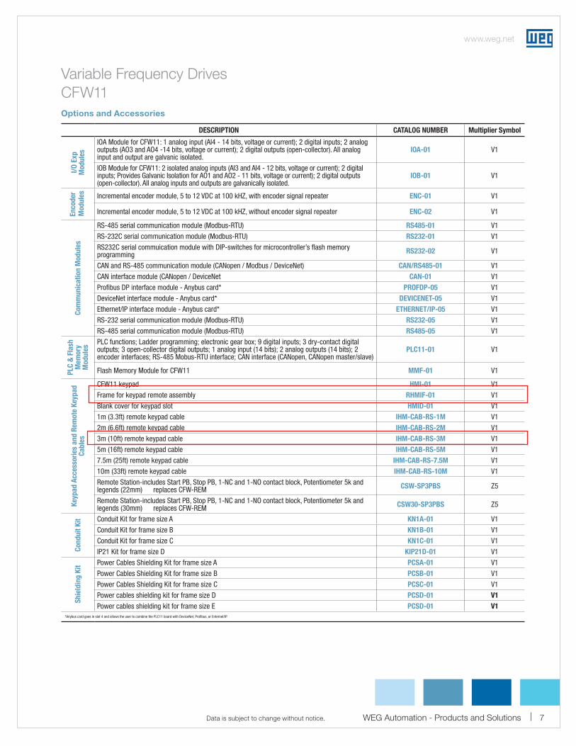
Variable Frequency Drives
CFW11
Options and Accessories
DESCRIPTION CATALOG NUMBER Multiplier Symbol
I/O
Exp
M
od
ule
s
IOA Module for CFW11: 1 analog input (AI4 - 14 bits, voltage or current); 2 digital inputs; 2 analog outputs (AO3 and AO4 -14 bits, voltage or current); 2 digital outputs (open-collector). All analog input and output are galvanic isolated.
IOA-01 V1
IOB Module for CFW11: 2 isolated analog inputs (AI3 and AI4 - 12 bits, voltage or current); 2 digital inputs; Provides Galvanic Isolation for AO1 and AO2 - 11 bits, voltage or current); 2 digital outputs (open-collector). All analog inputs and outputs are galvanically isolated.
IOB-01 V1
Incremental encoder module, 5 to 12 VDC at 100 kHZ, with encoder signal repeater ENC-01 V1
Incremental encoder module, 5 to 12 VDC at 100 kHZ, without encoder signal repeater ENC-02 V1
Com
mu
nic
ati
on
Mo
du
les
RS-485 serial communication module (Modbus-RTU) RS485-01 V1
RS-232C serial communication module (Modbus-RTU) RS232-01 V1
RS232C serial commuication module with DIP-switches for microcontroller’s flash memory programming RS232-02 V1
CAN and RS-485 communication module (CANopen / Modbus / DeviceNet) CAN/RS485-01 V1
CAN interface module (CANopen / DeviceNet CAN-01 V1
Profibus DP interface module - Anybus card* PROFDP-05 V1
DeviceNet interface module - Anybus card* DEVICENET-05 V1
Ethernet/IP interface module - Anybus card* ETHERNET/IP-05 V1
RS-232 serial communication module (Modbus-RTU) RS232-05 V1
RS-485 serial communication module (Modbus-RTU) RS485-05 V1
PLC
& F
lash
M
em
ory
M
od
ule
s
PLC functions; Ladder programming; electronic gear box; 9 digital inputs; 3 dry-contact digital outputs; 3 open-collector digital outputs; 1 analog input (14 bits); 2 analog outputs (14 bits); 2 encoder interfaces; RS-485 Mobus-RTU interface; CAN interface (CANopen, CANopen master/slave)
PLC11-01 V1
Flash Memory Module for CFW11 MMF-01 V1
Keyp
ad
Access
ori
es
an
d R
em
ote
Keyp
ad
C
ab
les
CFW11 keypad HMI-01 V1
Frame for keypad remote assembly RHMIF-01 V1
Blank cover for keypad slot HMID-01 V1
1m (3.3ft) remote keypad cable IHM-CAB-RS-1M V1
2m (6.6ft) remote keypad cable IHM-CAB-RS-2M V1
3m (10ft) remote keypad cable IHM-CAB-RS-3M V1
5m (16ft) remote keypad cable IHM-CAB-RS-5M V1
7.5m (25ft) remote keypad cable IHM-CAB-RS-7.5M V1
10m (33ft) remote keypad cable IHM-CAB-RS-10M V1
Remote Station-includes Start PB, Stop PB, 1-NC and 1-NO contact block, Potentiometer 5k and legends (22mm) replaces CFW-REM CSW-SP3PBS Z5
Remote Station-includes Start PB, Stop PB, 1-NC and 1-NO contact block, Potentiometer 5k and legends (30mm) replaces CFW-REM CSW30-SP3PBS Z5
Con
du
it K
it Conduit Kit for frame size A KN1A-01 V1
Conduit Kit for frame size B KN1B-01 V1
Conduit Kit for frame size C KN1C-01 V1
IP21 Kit for frame size D KIP21D-01 V1
Sh
ield
ing
Kit
Power Cables Shielding Kit for frame size A PCSA-01 V1
Power Cables Shielding Kit for frame size B PCSB-01 V1
Power Cables Shielding Kit for frame size C PCSC-01 V1
Power cables shielding kit for frame size D PCSD-01 V1
Power cables shielding kit for frame size E PCSD-01 V1
*Anybus card goes in slot 4 and allows the user to combine the PLC11 board with DeviceNet, Profibus, or Enternet/IP.
En
co
der
Mo
du
les
1-800-ASK-4WEG
www.weg.net
8
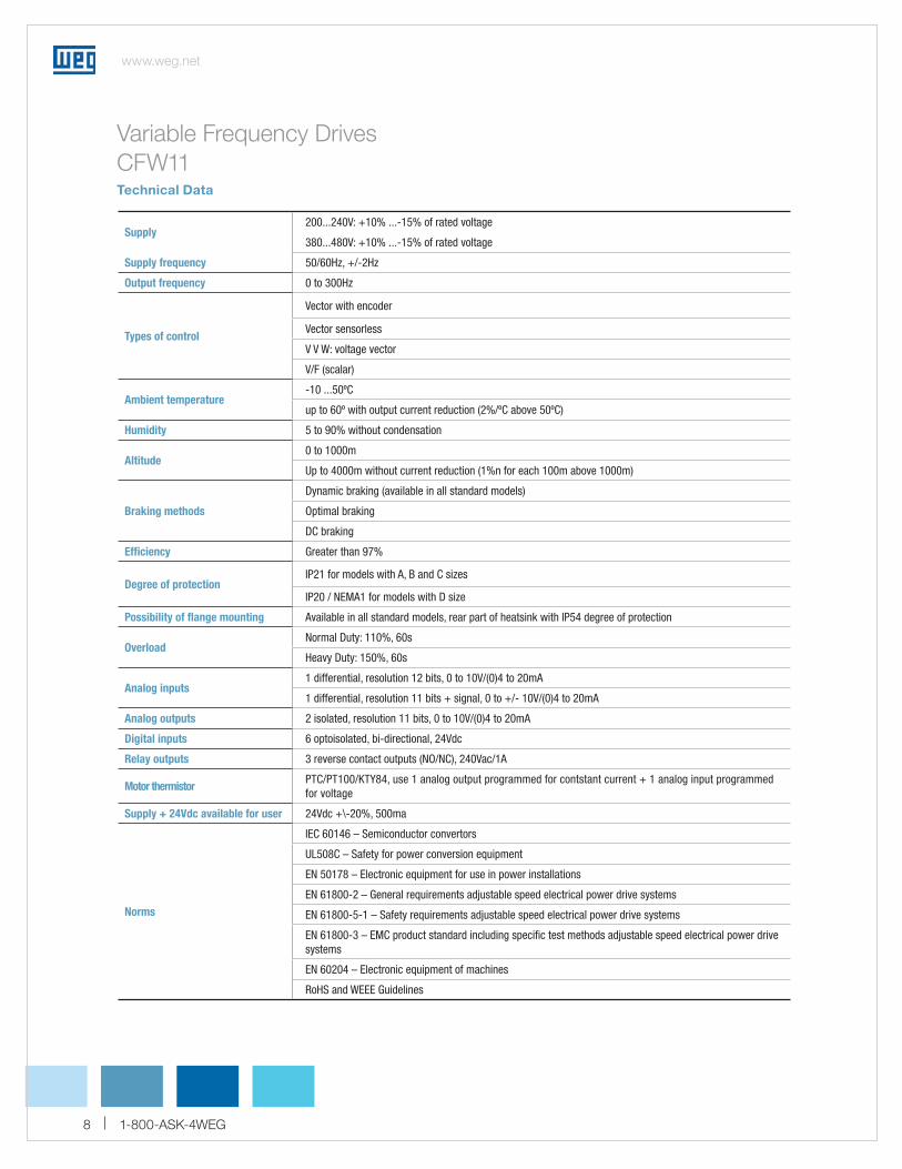
Supply200...240V: +10% ...-15% of rated voltage
380...480V: +10% ...-15% of rated voltage
Supply frequency 50/60Hz, +/-2Hz
Output frequency 0 to 300Hz
Types of control
Vector with encoder
Vector sensorless
V V W: voltage vector
V/F (scalar)
Ambient temperature-10 ...50ºC
up to 60º with output current reduction (2%/ºC above 50ºC)
Humidity 5 to 90% without condensation
Altitude0 to 1000m
Up to 4000m without current reduction (1%n for each 100m above 1000m)
Braking methods
Dynamic braking (available in all standard models)
Optimal braking
DC braking
Efficiency Greater than 97%
Degree of protectionIP21 for models with A, B and C sizes
IP20 / NEMA1 for models with D size
Possibility of flange mounting Available in all standard models, rear part of heatsink with IP54 degree of protection
OverloadNormal Duty: 110%, 60s
Heavy Duty: 150%, 60s
Analog inputs1 differential, resolution 12 bits, 0 to 10V/(0)4 to 20mA
1 differential, resolution 11 bits + signal, 0 to +/- 10V/(0)4 to 20mA
Analog outputs 2 isolated, resolution 11 bits, 0 to 10V/(0)4 to 20mA
Digital inputs 6 optoisolated, bi-directional, 24Vdc
Relay outputs 3 reverse contact outputs (NO/NC), 240Vac/1A
Motor thermistor PTC/PT100/KTY84, use 1 analog output programmed for contstant current + 1 analog input programmed for voltage
Supply + 24Vdc available for user 24Vdc +\-20%, 500ma
Norms
IEC 60146 – Semiconductor convertors
UL508C – Safety for power conversion equipment
EN 50178 – Electronic equipment for use in power installations
EN 61800-2 – General requirements adjustable speed electrical power drive systems
EN 61800-5-1 – Safety requirements adjustable speed electrical power drive systems
EN 61800-3 – EMC product standard including specific test methods adjustable speed electrical power drive systems
EN 60204 – Electronic equipment of machines
RoHS and WEEE Guidelines
Variable Frequency Drives
CFW11 Technical Data