Embed Size (px)
Citation preview
WBS 2.5 HF PMT SYSTEMY. Onel
University of Iowa
US CMS DOE/NSF Review
May8-10, 2001
Outline
• HF PMT Specifications
• Previous Experimental Data on Photodetectors by HF Group
• Tasks of the Test System:
• Procedures for measurements
• Quality Assurance
• HF PMT Test Station
• Preliminary HF-PMT Candidate Tests/Specs
• Experimental Data
• Manpower and expert team to install the test system
• Vendors
• Milestones
• Conclusions
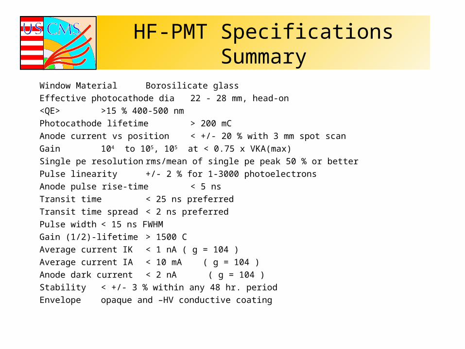
HF-PMT Specifications SummaryWindow Material Borosilicate glass
Effective photocathode dia 22 - 28 mm, head-on
<QE> >15 % 400-500 nm
Photocathode lifetime > 200 mC
Anode current vs position < +/- 20 % with 3 mm spot scan
Gain 104 to 105, 105 at < 0.75 x VKA(max)
Single pe resolution rms/mean of single pe peak 50 % or better
Pulse linearity +/- 2 % for 1-3000 photoelectrons
Anode pulse rise-time < 5 ns
Transit time < 25 ns preferred
Transit time spread < 2 ns preferred
Pulse width < 15 ns FWHM
Gain (1/2)-lifetime > 1500 C
Average current IK < 1 nA ( g = 104 )
Average current IA < 10 mA ( g = 104 )
Anode dark current < 2 nA ( g = 104 )
Stability < +/- 3 % within any 48 hr. period
Envelope opaque and –HV conductive coating
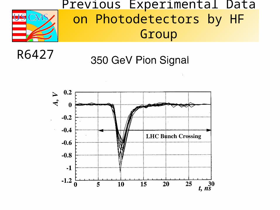
Previous Experimental Data on Photodetectors by HF Group
R6427
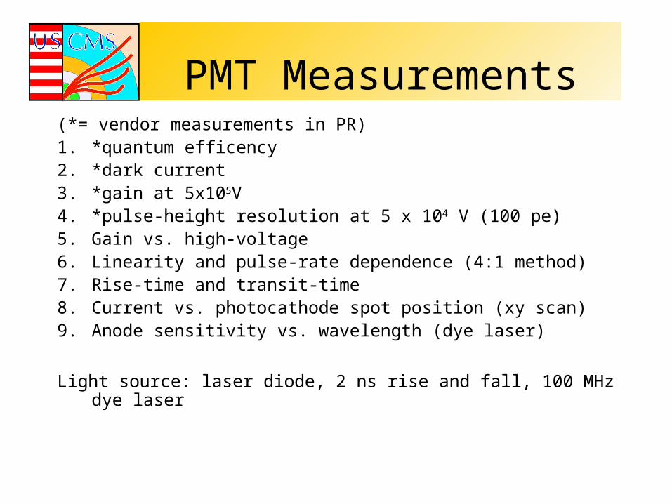
PMT Measurements(*= vendor measurements in PR)1. *quantum efficency2. *dark current3. *gain at 5x10⁵V4. *pulse-height resolution at 5 x 10⁴ V (100 pe)5. Gain vs. high-voltage6. Linearity and pulse-rate dependence (4:1 method)7. Rise-time and transit-time8. Current vs. photocathode spot position (xy scan)9. Anode sensitivity vs. wavelength (dye laser)
Light source: laser diode, 2 ns rise and fall, 100 MHz dye laser
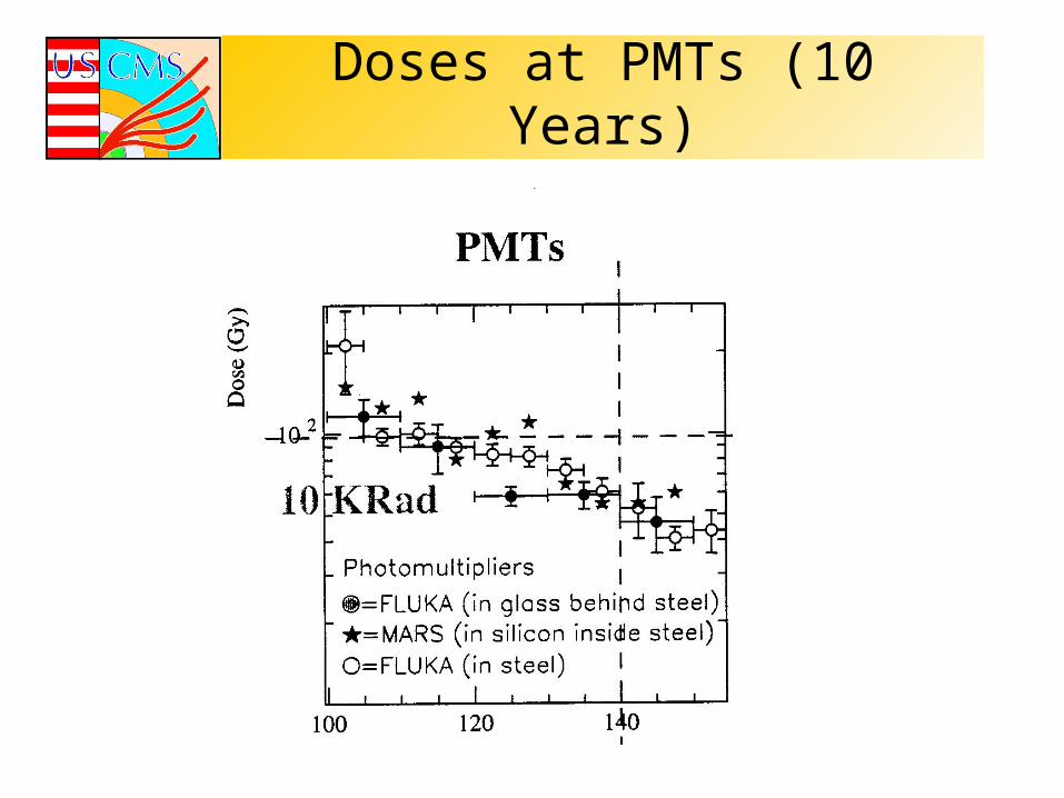
Doses at PMTs (10 Years)
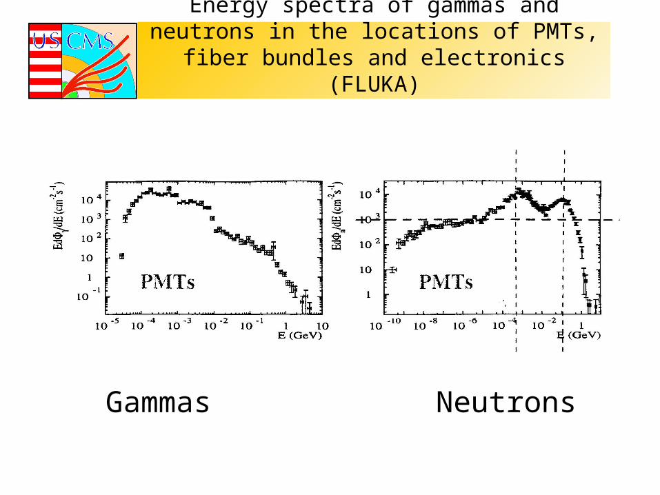
Energy spectra of gammas and neutrons in the locations of PMTs, fiber bundles and electronics
(FLUKA)
Gammas Neutrons
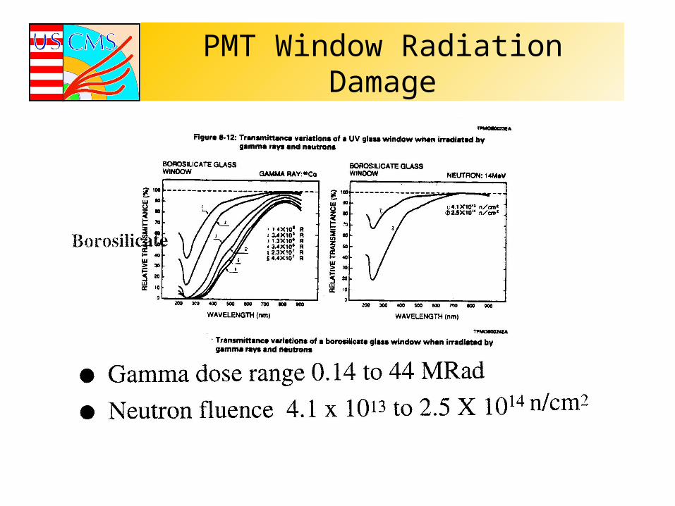
PMT Window Radiation Damage
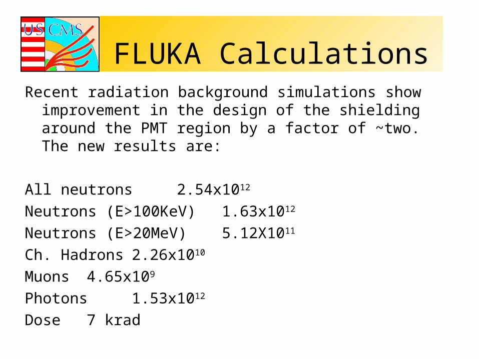
FLUKA CalculationsRecent radiation background simulations show improvement in
the design of the shielding around the PMT region by a factor of ~two. The new results are:
All neutrons 2.54x10¹²
Neutrons (E>100KeV) 1.63x10¹²
Neutrons (E>20MeV) 5.12X10¹¹
Ch. Hadrons 2.26x10¹⁰
Muons 4.65x10⁹
Photons 1.53x10¹²
Dose 7 krad

Tasks of the PMT Test System:
HF PMT Quality Control and Test System will address the following items:
• label and catalogue each PMT at delivery and storage;
• mechanical assembly with HV power supply and base;
• installation in Test Boxes : individually or in groups;
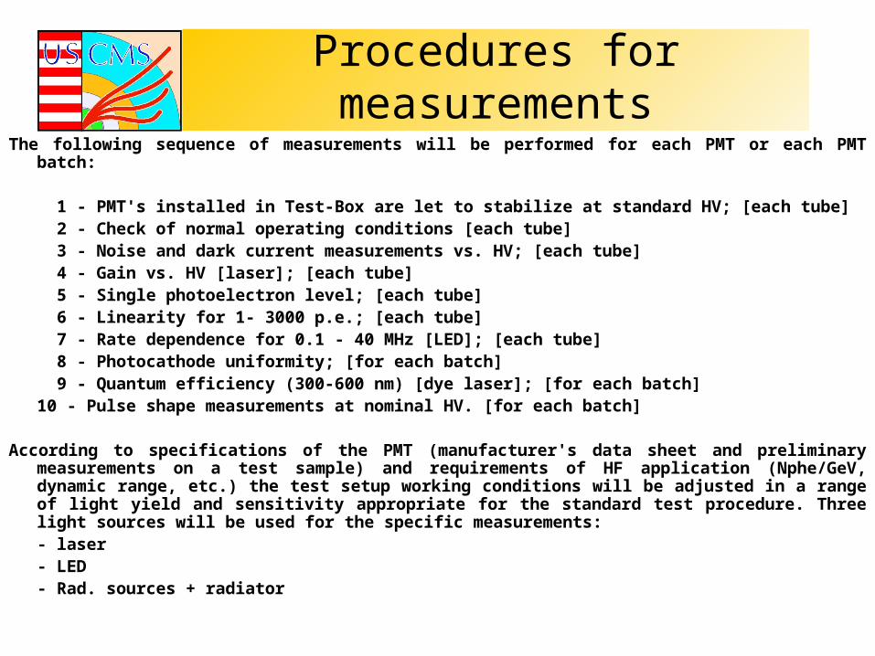
Procedures for measurementsThe following sequence of measurements will be performed for each PMT or each PMT batch:
1 - PMT's installed in Test-Box are let to stabilize at standard HV; [each tube] 2 - Check of normal operating conditions [each tube] 3 - Noise and dark current measurements vs. HV; [each tube] 4 - Gain vs. HV [laser]; [each tube] 5 - Single photoelectron level; [each tube] 6 - Linearity for 1- 3000 p.e.; [each tube] 7 - Rate dependence for 0.1 - 40 MHz [LED]; [each tube] 8 - Photocathode uniformity; [for each batch] 9 - Quantum efficiency (300-600 nm) [dye laser]; [for each batch]10 - Pulse shape measurements at nominal HV. [for each batch]
According to specifications of the PMT (manufacturer's data sheet and preliminary measurements on a test sample) and requirements of HF application (Nphe/GeV, dynamic range, etc.) the test setup working conditions will be adjusted in a range of light yield and sensitivity appropriate for the standard test procedure. Three light sources will be used for the specific measurements: - laser - LED- Rad. sources + radiator
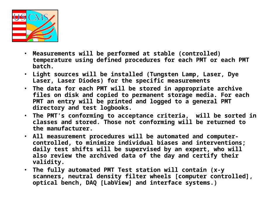
• Measurements will be performed at stable (controlled) temperature using defined procedures for each PMT or each PMT batch.
• Light sources will be installed (Tungsten Lamp, Laser, Dye Laser, Laser Diodes) for the specific measurements
• The data for each PMT will be stored in appropriate archive files on disk and copied to permanent storage media. For each PMT an entry will be printed and logged to a general PMT directory and test logbooks.
• The PMT's conforming to acceptance criteria, will be sorted in classes and stored. Those not conforming will be returned to the manufacturer.
• All measurement procedures will be automated and computer-controlled, to minimize individual biases and interventions; daily test shifts will be supervised by an expert, who will also review the archived data of the day and certify their validity.
• The fully automated PMT Test station will contain (x-y scanners, neutral density filter wheels [computer controlled], optical bench, DAQ [LabView] and interface systems.)
Quality Assurance• At the manufacturer• testing/preselection as they arrive• beam/calibration tests during the installation
period• PMT can be replaced
Tests required of the vendor on each tube
1. Measure and report the quantum efficiency of the tube at 420nm.
2. Determine the voltage at which a current gain of 5x10⁴ is reached.
• Measure the dark current at a current gain of 5x10⁴.
Additional testsThe vendor shall determine the pulse height resolution
at a gain of 5x10⁴ using the following method or some other method agreed on between us and vendor.
The PMT pulse height resolution shall deviate less then 50% from the ideal resolution (defined as sigma/mean equal to 1/sqrt(t) where Npe is the average number of photoelectrons produced by the photocathode for a given light pulse intensity) at a current gain of 5x10⁴. The vendor and University shall agree on an appropriate test to determine that this resolution specification is met.
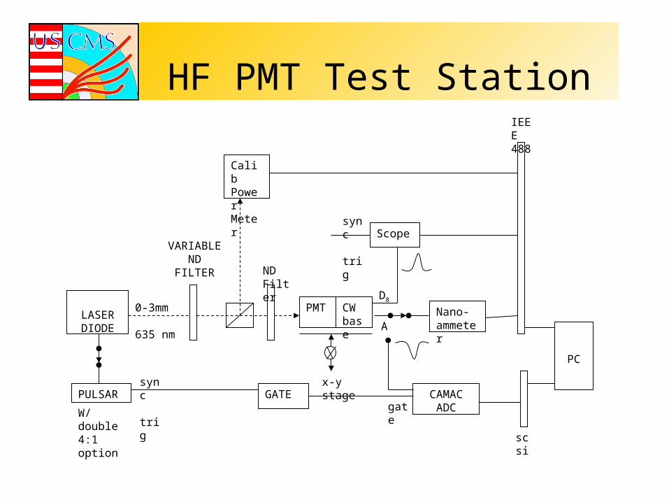
HF PMT Test Station
CAMACADC
PC
scsi
GATEPULSAR
LASER DIODE
VARIABLEND
FILTER
0-3mm
635 nm
CWbase
PMT Nano-ammeter
IEEE488
Scope
CalibPower Meter
ND Filter
sync
trig
sync
trig
W/ double 4:1 option
x-y stage
gate
D8
A
Preliminary HF-PMT Candidate Tests/Specs
Measurements
1. Anode Dark Current
2. Leading Edge Rise Time
3. Pulse Width
4. Transit Time
5. Transit Time – Spread
6. Current Gain
7. Linearity

Pulse Setup
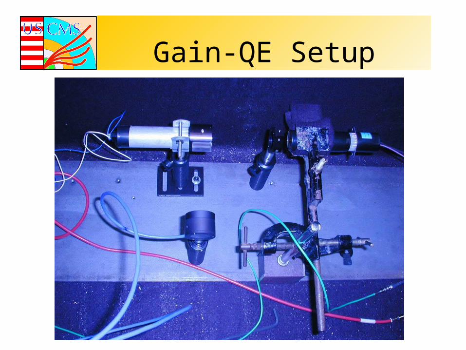
Gain-QE Setup
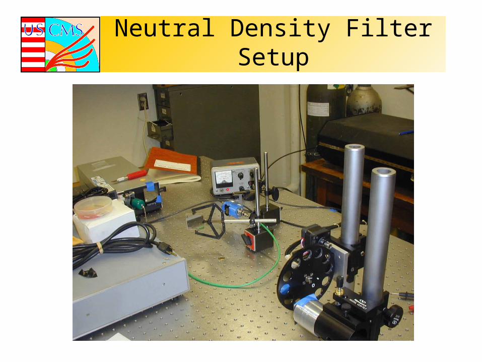
Neutral Density Filter Setup
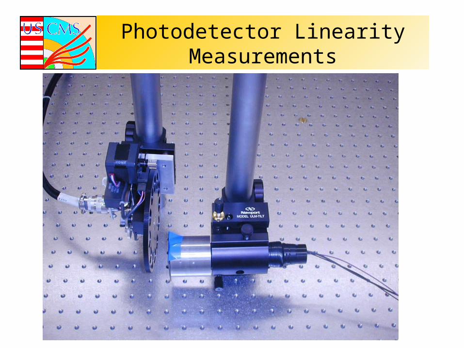
Photodetector Linearity Measurements
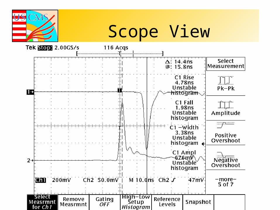
Scope View
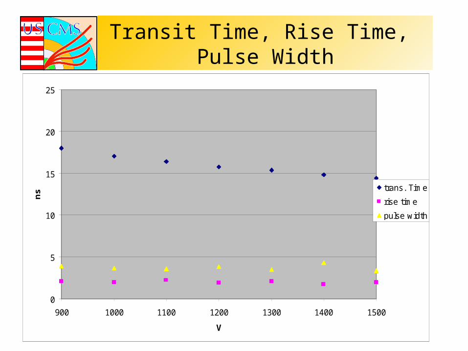
Transit Time, Rise Time, Pulse Width
0
5
10
15
20
25
900 1000 1100 1200 1300 1400 1500
V
ns trans. Time
rise time
pulse width
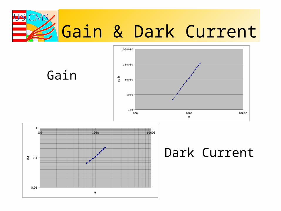
Gain & Dark Current
0.01
0.1
1
100 1000 10000
V
nA
100
1000
10000
100000
1000000
100 1000 10000
Vg
ainGain
Dark Current
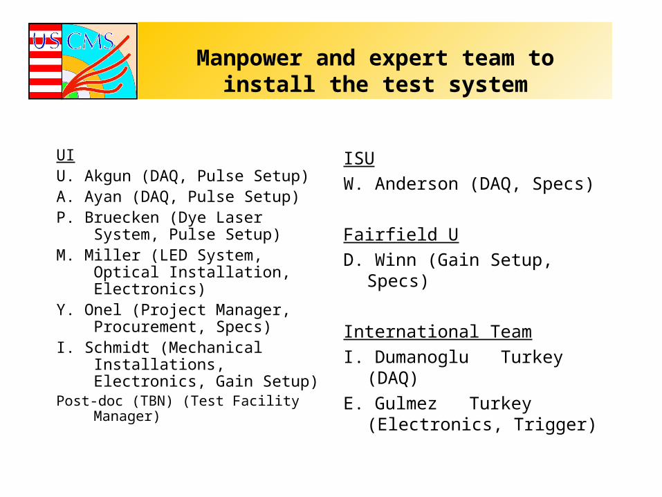
Manpower and expert team to install the test system
UIU. Akgun (DAQ, Pulse Setup)A. Ayan (DAQ, Pulse Setup)P. Bruecken (Dye Laser System,
Pulse Setup)M. Miller (LED System, Optical
Installation, Electronics)Y. Onel (Project Manager,
Procurement, Specs)I. Schmidt (Mechanical
Installations, Electronics, Gain Setup)
Post-doc (TBN) (Test Facility Manager)
ISU
W. Anderson (DAQ, Specs)
Fairfield U
D. Winn (Gain Setup, Specs)
International Team
I. Dumanoglu Turkey (DAQ)
E. Gulmez Turkey (Electronics, Trigger)
Vendors
• Hamamatsu Corp
• Burle Industries
• Electron Tube Int (EMI)
• Photonis (phillips)
• ADIT
MilestonesDraft RFP March.15.01Evaluate samples May.15.01PMT test station ready August.15.01Final contract signed September.15.01Delivery 1st batch 100 PMTS November.1.01Delivery last batch January.1.03
*Assuming delivery of 200-300 PMT’s after 3 months of receiving order. Then delivery 200-300 PMT’s per month as last batch delivered by January 1, 2003.
*We budget total of 1 hour to unpack, test, label, repack, and enter, merge publish & archive data 2700 PMT. The selection database will be maintained for each PMT together with the base and front end electronics.
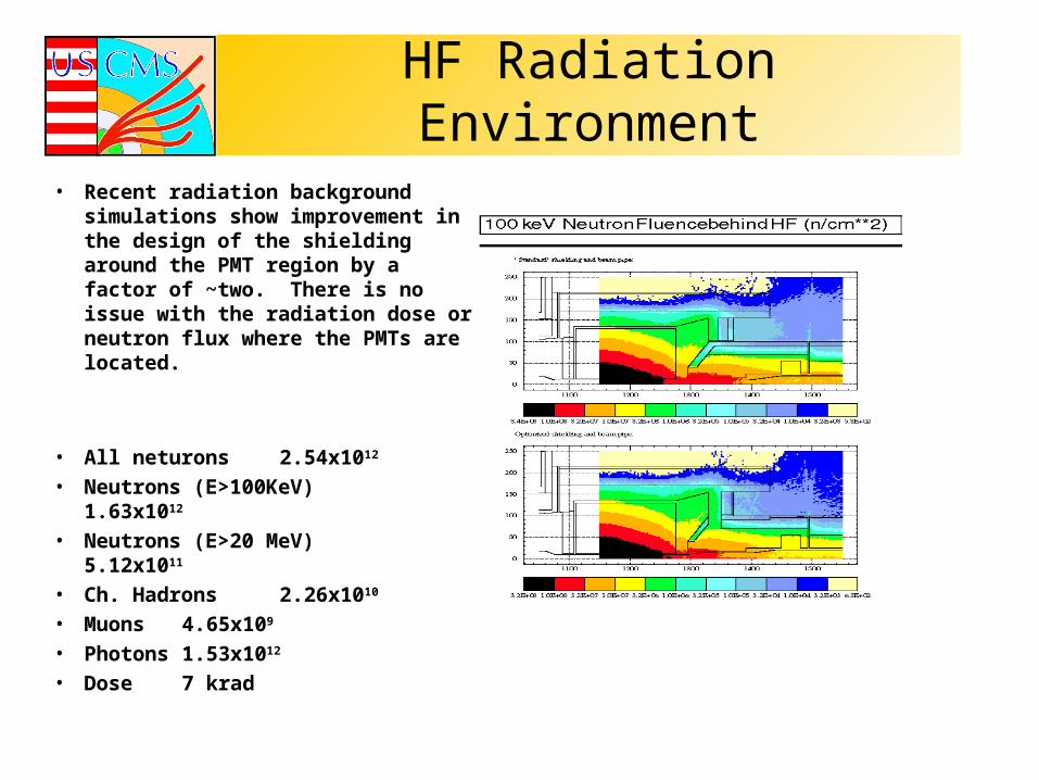
HF Radiation Environment• Recent radiation background simulations
show improvement in the design of the shielding around the PMT region by a factor of ~two. There is no issue with the radiation dose or neutron flux where the PMTs are located.
• All neturons 2.54x10¹²
• Neutrons (E>100KeV) 1.63x10¹²
• Neutrons (E>20 MeV) 5.12x10¹¹
• Ch. Hadrons 2.26x10¹⁰
• Muons 4.65x10⁹
• Photons 1.53x10¹²
• Dose 7 krad
Other Issues
• Scintillation of the PMT window is only a concern if the dose rate is >0.03 rad/sec. For HF, the estimate is 0.00002 rad/sec (factor of 1000 less).
• Ambient He partial pressure in air (0.53 Pa) will not be a problem with borosilicate window. Partial pressure will change 10 times in 10 years but will remain below the danger level by a factor of ~50000.
• Nitrogen gas will be circulated inside the ROBox against He leak from cryogenics and temperature fluctuations (+/- 2 degrees should not be a problem).
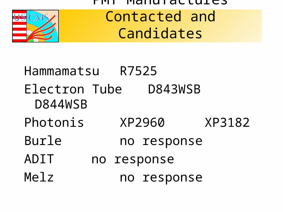
PMT Manufactures Contacted and Candidates
Hammamatsu R7525
Electron Tube D843WSBD844WSB
Photonis XP2960 XP3182
Burle no response
ADIT no response
Melz no response
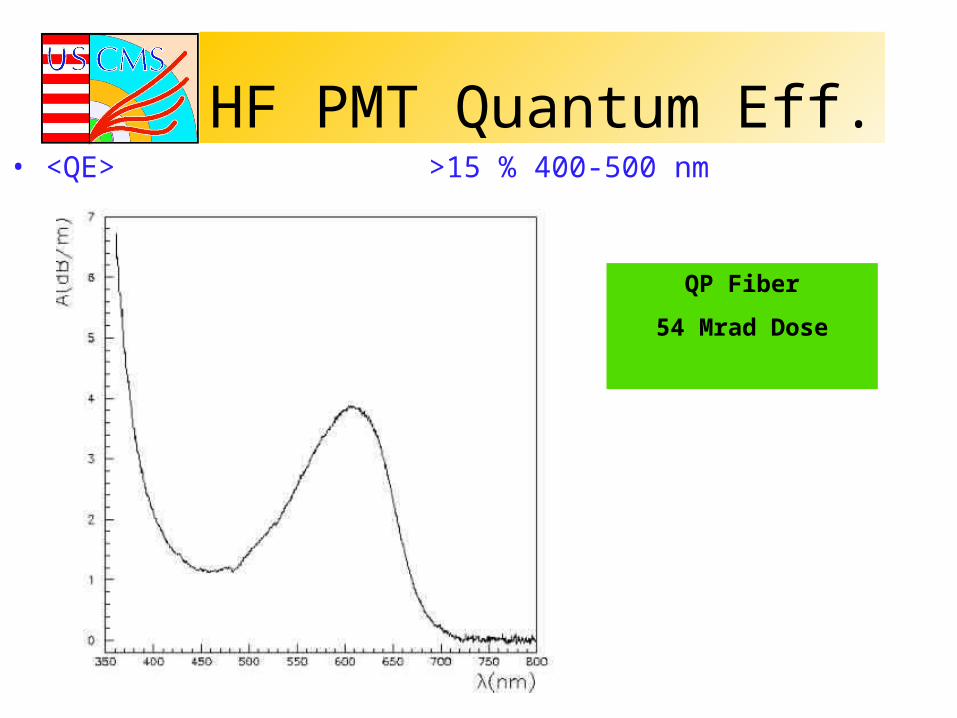
HF PMT Quantum Eff.• <QE> >15 % 400-500 nm
QP Fiber
54 Mrad Dose
Tube Base
• Prototype completed end of January– Cockroft-Walton multiplier style base– Series resonant sine-wave converter invented by Claudio
Rivetta and implemented by Sten Hansen (Fermilab)• Very low noise• Low power consumption
– Last dynode voltage sags 0.5 V from 0 to 200 microamps – factor of 20 headroom for the hottest tubes at eta = 5
– Iowa State and Texas Tech Universities responsible for specifications and testing
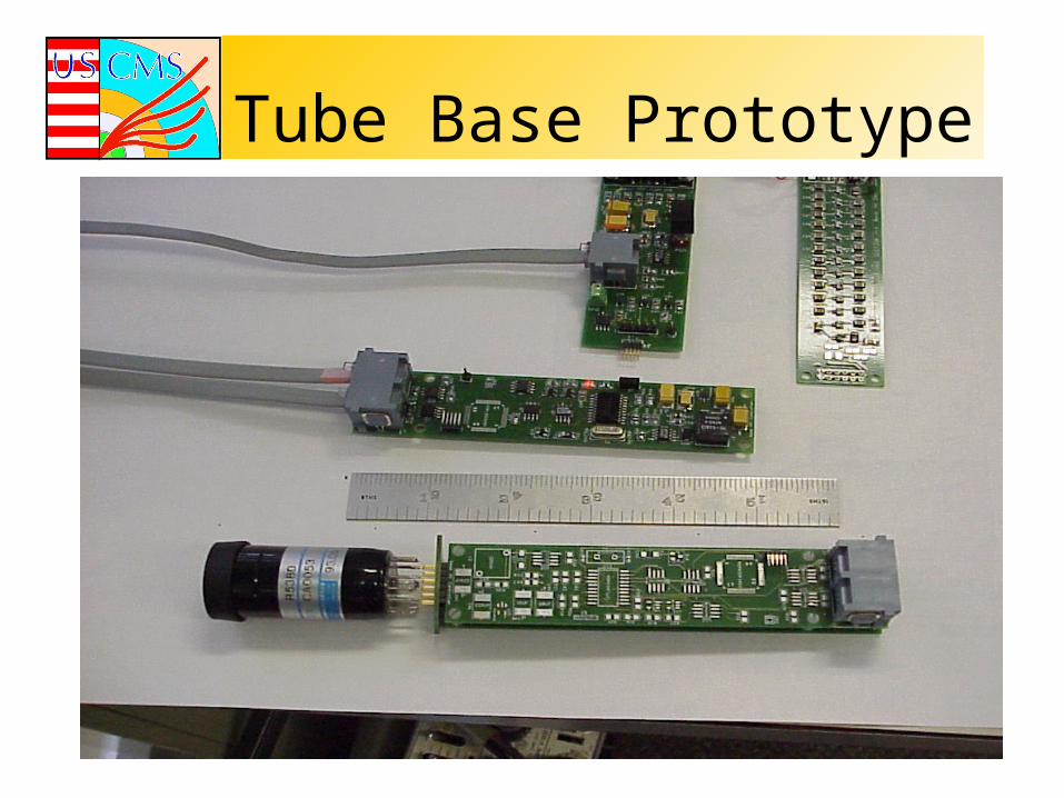
Tube Base Prototype
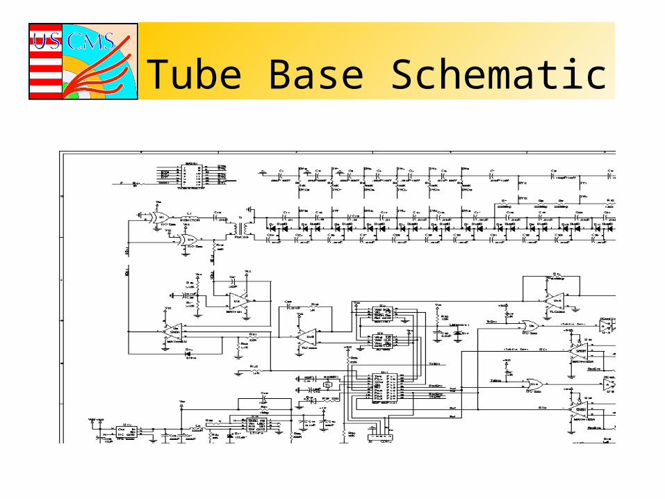
Tube Base Schematic
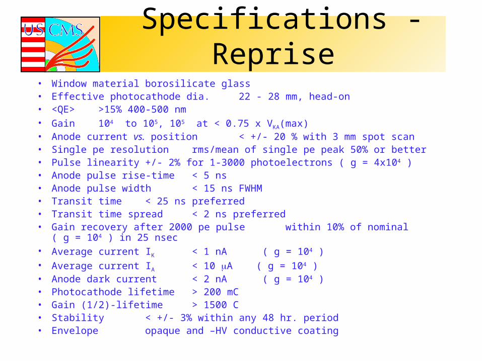
Specifications - Reprise• Window material borosilicate glass• Effective photocathode dia. 22 - 28 mm, head-on• <QE> >15% 400-500 nm• Gain 104 to 105, 105 at < 0.75 x VKA(max) • Anode current vs. position < +/- 20 % with 3 mm spot scan • Single pe resolution rms/mean of single pe peak 50% or better• Pulse linearity +/- 2% for 1-3000 photoelectrons ( g = 4x10⁴ )• Anode pulse rise-time < 5 ns• Anode pulse width < 15 ns FWHM• Transit time < 25 ns preferred• Transit time spread < 2 ns preferred• Gain recovery after 2000 pe pulse within 10% of nominal ( g = 104 ) in 25 nsec• Average current IK < 1 nA ( g = 104 )• Average current IA < 10 A ( g = 104 )• Anode dark current < 2 nA ( g = 104 )• Photocathode lifetime > 200 mC • Gain (1/2)-lifetime > 1500 C• Stability < +/- 3% within any 48 hr. period • Envelope opaque and –HV conductive coating

Procurement/Testing Strategy
• Hamamatsu, for example, will deliver 200 PMTs/month. We need ~14.3 months.
• PMTs will be supplied with gain of 3x10⁵ with gain measurements at 1300, 1500 and 1650 V by Hamamatsu.
• The cost estimate is 690 K$ based on 110 Yen/$.• Sole source or bidding? There are several PMTs that would do the job. • We should be able to test at the same rate as production, i.e. 10 PMTs/day,
on average.• The PMT responsibilities are with Iowa, ISU and Fairfield.
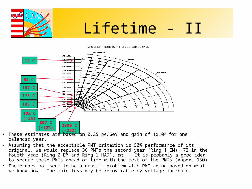
Lifetime - II
2300 C(~25%)
807 C(~12%)
192 C(~3%)
183 C
175 C
157 C
84 C
12 C
• These estimates are based on 0.25 pe/GeV and gain of 1x10⁵ for one calendar year.• Assuming that the acceptable PMT criterion is 50% performance of its original, we would
replace 36 PMTs the second year (Ring 1 EM), 72 in the fourth year (Ring 2 EM and Ring 1 HAD), etc. It is probably a good idea to secure these PMTs ahead of time with the rest of the PMTs (Appox. 150).
• There does not seem to be a drastic problem with PMT aging based on what we know now. The gain loss may be recoverable by voltage increase.
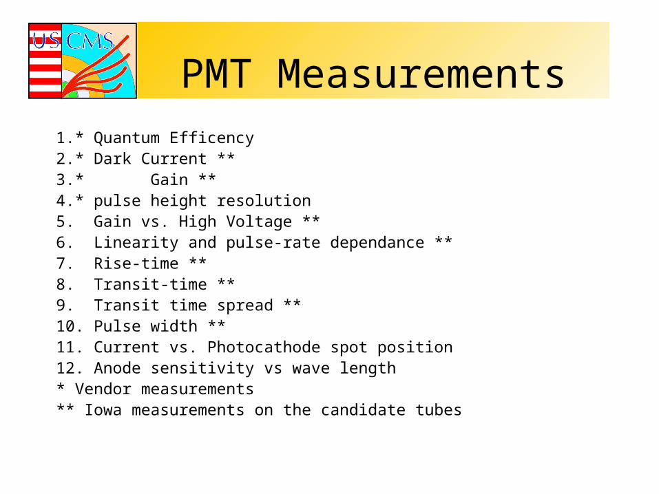
PMT Measurements
1.* Quantum Efficency2.* Dark Current **3.* Gain **4.* pulse height resolution5. Gain vs. High Voltage **6. Linearity and pulse-rate dependance **7. Rise-time **8. Transit-time **9. Transit time spread **10. Pulse width **11. Current vs. Photocathode spot position12. Anode sensitivity vs wave length* Vendor measurements** Iowa measurements on the candidate tubes
Conclusions• We had PRR at CERN in Feburary• We have evaluated the performance of the candidate PMTs• RFP is drafted and we expect to sign the final contract in
early September• We have designed the PMT test station and built a small
prototype version to evaluate the candidate PMTs.• Computer controlled x-y scanner and neutral density fibers
are built and presently under test• Major components of the final PMT station and related
electronics are purchased and the system will be ready by mid-August
• Design of CW bases are in progress at FNAL• The PMT readout project is on time and budget
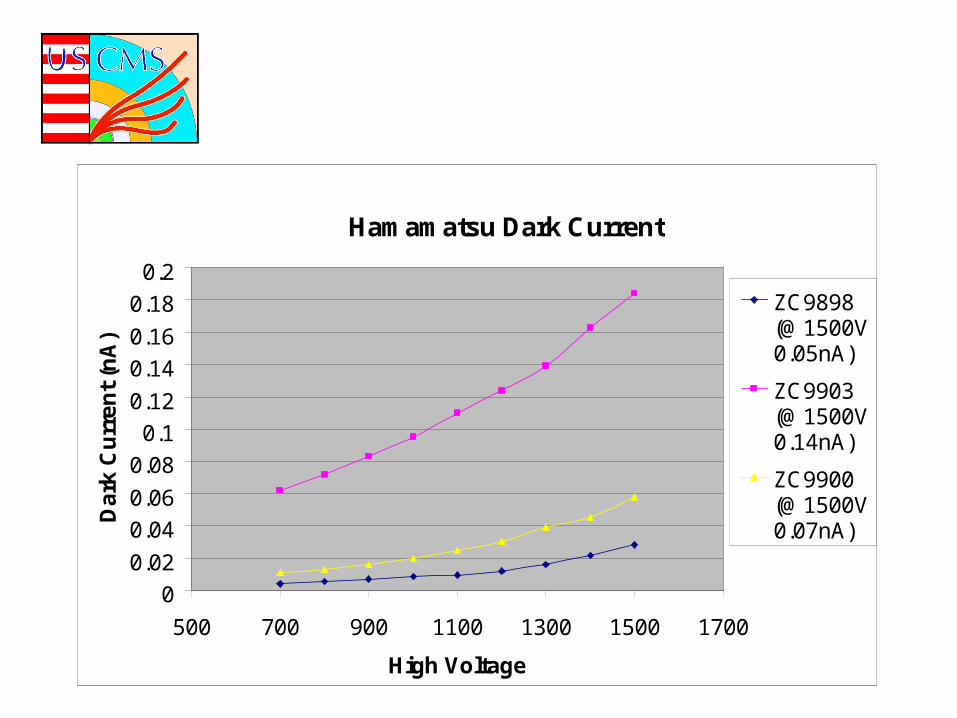
Hamamatsu Dark Current
0
0.02
0.04
0.06
0.08
0.1
0.12
0.14
0.16
0.18
0.2
500 700 900 1100 1300 1500 1700
High Voltage
Da
rk C
urr
en
t (n
A)
ZC9898(@1500V0.05nA)
ZC9903(@1500V0.14nA)
ZC9900(@1500V0.07nA)
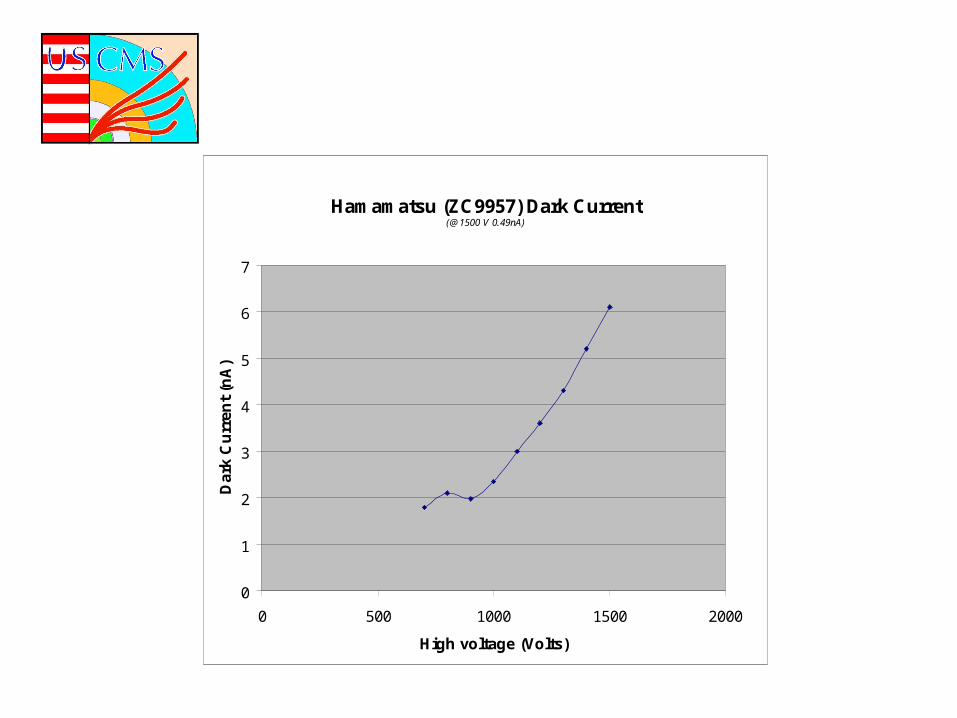
Hamamatsu (ZC9957) Dark Current(@1500 V 0.49nA)
0
1
2
3
4
5
6
7
0 500 1000 1500 2000
High voltage (Volts)
Dar
k C
urr
ent
(nA
)