Embed Size (px)
Citation preview

1
CONSIDER MAKING A TECHNICAL PRESENTATION AT AN UPCOMING CHEW & CHAT MEETING…
SHARE WHAT YOU KNOW…
LEARN SOMETHING NEW AND PRESENT IT…
CONTACT TIM AD4CJ [email protected]
WCARES NEEDS YOU!
2
Transmission Line Transformers
Chokes, Baluns and Ununs
A WCARES presentation based upon information garnered from books
and the internet from Amidon, Wikipedia, Jerry Sevick W2FMI, Tom
Rauch W8JI, and technical notes from DX
Engineering and Balun Designs.
3
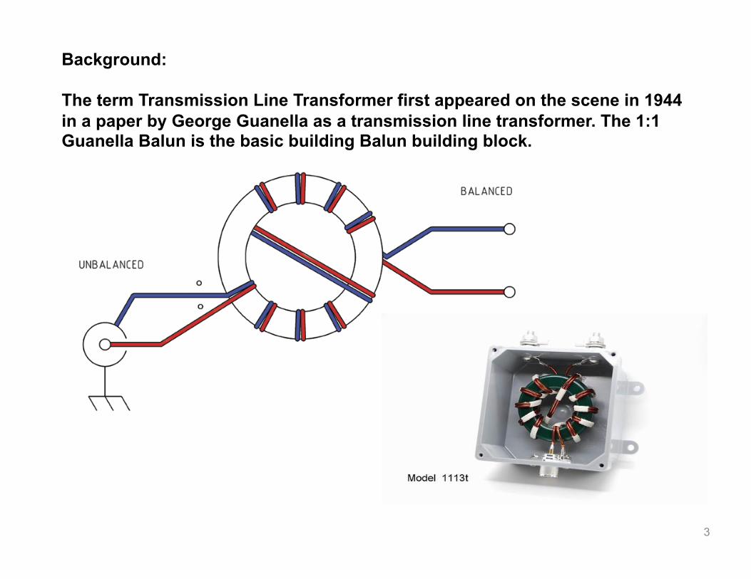
Background:
The term Transmission Line Transformer first appeared on the scene in 1944 in a paper by George Guanella as a transmission line transformer. The 1:1 Guanella Balun is the basic building Balun building block.

4
Then the 4:1 Unun was presented by Clyde Ruthroff in 1959

5
Then in 1978 Joe Reisert W1JR enhanced the 1:1 balun idea further by winding that coil of coaxial transmission-line onto a toroid-core. This formed a ‘Choke Balun’.

6
Balun is an acronym for :
BALanced to Unbalanced
Unun is an acronym for:
Unbalanced to Unbalanced
7
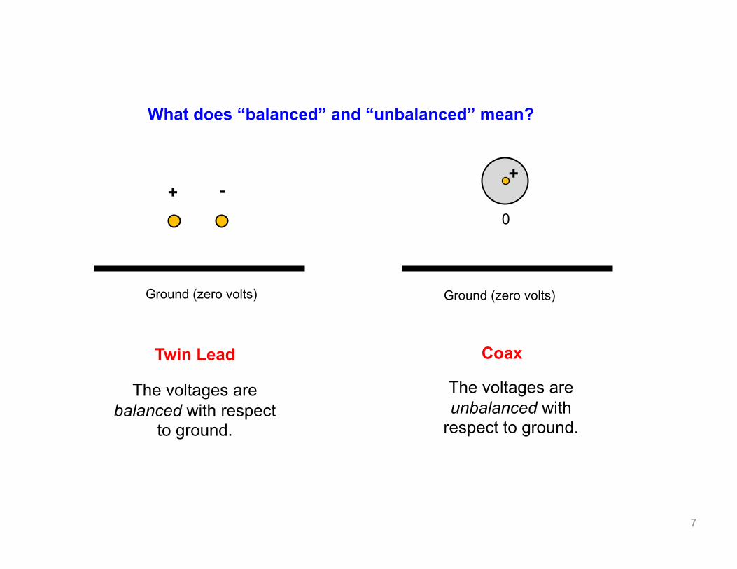
Ground (zero volts)
+ -
Ground (zero volts)
+
0
The voltages are unbalanced with
respect to ground.
The voltages are balanced with respect
to ground.
Coax Twin Lead
What does “balanced” and “unbalanced” mean?
8
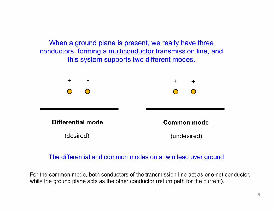
When a ground plane is present, we really have three conductors, forming a multiconductor transmission line, and
this system supports two different modes.
+ -
Differential mode
(desired)
+ +
Common mode
(undesired)
The differential and common modes on a twin lead over ground
For the common mode, both conductors of the transmission line act as one net conductor, while the ground plane acts as the other conductor (return path for the current).

9
Ground
Differential mode: currents are equal and opposite
Ground
Common mode: a net current flows on the two conductors

10
If the two terminals of the load or source do not carry equal currents, some current will flow in a loop through the ground or along the outside of the shield.
The outside of the shield is isolated by skin effect in the conductor wall.
At radio frequencies the outside of the shield can be treated as an independent conductor connected to the “inside shield” at the ends of the coax.
Most coaxial baluns make the outside shield connection a high impedance while not disturbing the inside operation.

11
If you try to feed a dipole antenna directly with coax, there will be a common mode current on the coax.
No balun
Coaxial line currents

12
A common-‐mode choke balun, for example, performs the balun funcDon by puEng impedance in the path of common-‐mode currents and is therefore a balun.

13
The MFJ-854 RF Current Meter reads true RF current.
It can accurately measure actual RF currents flowing in antenna elements, radials, ground wires and on the outside of coax feedlines.
You can actually measure the common mode current on the outer shield of coaxial cable With a clamp-on RF Current Meter

14
6:1 1:4 GUANELLA CURRENT BALUN
1:1 Dipole Feedpoint 1:1 Choke Balun

15
Low Power 4:1
Low Power 9:1
Bifilar
Trifilar
A bifilar winding is often used to improve the coupling between the primary and secondary of the transformer. A bifilar winding is the winding in close proximity of the primary and secondary wires over the same core.
High Power 4:1 Bifilar

16
A common misconception and when using a loop, doublet or double extended Zep (and several others) for multiband operation requires a high ratio balun (6:1, 9:1, 12:1) to manage the transition from high impedance ladder line / open wire feedline to coax.
An example would be the primary band a full size loop is cut for. Typically this will have a 100-125 ohm feedpoint impedance and when divided by the ratio of the balun, i.e. 12:1 (if trying to match 600 ohm open wire) the resulting 8-10 ohms is impossible for all but the absolute best tuner to match.
This problem can be even worse for doublets. If the doublet is cut for resonance on the primary or lowest band, the feedpoint impedance will be around 60-70 ohms and the resulting impedance, after a high ratio balun, will be even lower than a similar loop antenna.
The solution is using a balun with a much lower ratio such as a 1:1 or a 4:1 which will transform the balanced line to the unbalanced coax.

17
The RF power loss of 450Ω ladder line is lower than the loss of all 50Ω and 75Ω commercial hard line and CATV hardline cables 7/8" and smaller, and is equal to the loss of 1-1/4" hardline! (Loss figures from The ARRL Antenna Book)
The loss of 450Ω ladder line is typically 1/10 of the loss of RG -213.
USING LADDER LINE WITH BALUNS TO CREATE A LOW LOSS TRANSMISSION LINE

18
When a balun or unun is wound correctly, a higher power rating will also mean a higher efficiency, low SWR and excellent overall Return Loss.
Consequently, if you're a QRP operator running 5 or 10 watts, the best choice for you may well be the balun rated at 3 or 5kW.
Of course this is usually impractical if your intended use is portable operation and want something small and light, but for a permanent installation the higher power is a much better choice. Keep in mind this may not be the case when using an inexpensive balun rated at high power. It is almost impossible to build a $20-30 balun that also offers high efficiency.

19
Baluns are used to connect coax (unbalanced line) to dipole antennas (balanced).
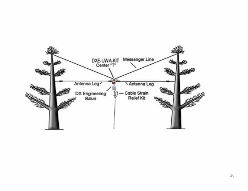
20

21
This is a popular antenna system. A simple mulD-‐band dipole may be constructed by first choosing the lowest band on which operaDon is desired.
The overall length of the mulD-‐band dipole antenna should be shorter than one-‐half wavelength.
For best efficiency, ladder line feed and a good antenna tuner with balanced connecDons are required. The ideal balun is a 1:1 raDo DX Engineering special applicaDon tuner balun.
It can be connected through a short length of coaxial cable to an unbalanced tuner for tuning the different bands.
Dave, KI4PSR has and antenna similar to this.
Ladder Line or Open Wire fed Dipoles or Doublets

22
ODD ONE EIGHTH WAVELENGTHS
Ladder feedline for a multi-band dipole must be in odd multiple lengths of 1/8 wavelength on the lowest operating frequency.

23
Long wire antennas are typically horizontal antennas, fed
at one end, and well over 1/2-‐wavelength long at the lowest operaDng frequency.
The impedance of a long wire antenna varies as the frequency is changed, but the normally accepted values are from a few hundred to a few thousand ohms depending on length, height, ground condiDons and frequency.
A 4:1 balun should be used in this installaDon. The counterpoise length should be ¼ wave on the lowest frequency planned.
Ed, WB4RHQ has an antenna like this.
Long-‐Wire Antennas

24
Antennas that are typically horizontal antennas, fed at one
end, and less than 1/2-‐wavelength long at the lowest operaDng frequency.
According to Balun Designs, a 9:1 unun is used.
Please keep in mind this design is a compromise antenna and intended primarily for use by those living in restricted antenna areas or for temporary / emergency installaDons where simplicity and broad HF coverage is important.
Recommended Wire Lengths (in feet) for Coverage of 160m through 10m
53 59 72 88.5 98.5 124.5 135 146 162 175
Tim, AD4CJ has an 88.5’ antenna like this.
Shorter End Fed Antennas

25
The True or Conventional Windom antenna, shown below, is fed with a single-wire line, and fed as an unbalanced system against a reasonable RF ground or counterpoise. The feed is similar to a longwire antenna, except the horizontal wire is fed with a few percent offset from the center.
The best balun for both antennas, assuming they operated where standing waves on the feed system are low, are 4:1 baluns.
26
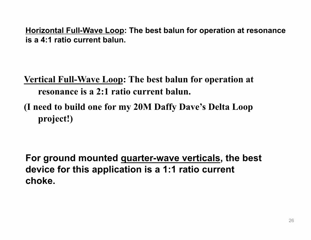
Horizontal Full-Wave Loop: The best balun for operation at resonance is a 4:1 ratio current balun.
Vertical Full-Wave Loop: The best balun for operation at resonance is a 2:1 ratio current balun.
(I need to build one for my 20M Daffy Dave’s Delta Loop project!)
For ground mounted quarter-wave verticals, the best device for this application is a 1:1 ratio current choke.
27
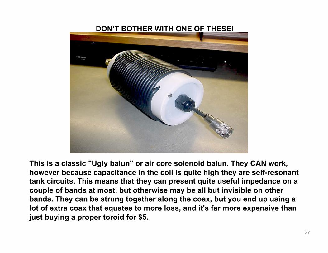
DON’T BOTHER WITH ONE OF THESE!
This is a classic "Ugly balun" or air core solenoid balun. They CAN work, however because capacitance in the coil is quite high they are self-resonant tank circuits. This means that they can present quite useful impedance on a couple of bands at most, but otherwise may be all but invisible on other bands. They can be strung together along the coax, but you end up using a lot of extra coax that equates to more loss, and it's far more expensive than just buying a proper toroid for $5.

28
Many thanks to Balun Designs for their generosity:
Hi Dave,
For your teaching use we will sell two of the kits to you for $30 each plus shipping so a total of $70.90 complete.

29
CONSIDER MAKING A TECHNICAL PRESENTATION AT AN UPCOMING CHEW & CHAT MEETING…
SHARE WHAT YOU KNOW…
LEARN SOMETHING NEW AND PRESENT IT…
CONTACT TIM AD4CJ [email protected]
WCARES NEEDS YOU!

30
Balun Designs, in collaboration with Fair Rite products, has developed what we consider to be the best single core 1:1 feedline isolation balun available today. By reviewing the scans shown below you can see what we're referring to. Notice how the level of choking impedance ramps up very quickly developing 3100 ohms on 160m and continues at even higher levels across the full HF spectrum. This is a very difficult level to achieve and maintain for a single core balun and is truly exceptional. What’s more, the transformation, SWR and return loss are near perfect. This balun is unique in the marketplace today.