Embed Size (px)
Citation preview
Abstract—This paper presents a shunt active power filter
with battery interface for uninterruptible power supply (UPS)
operation. The proposed unified architecture is composed by a
single-phase ac-dc converter from the power grid side and by a
bidirectional isolated dc-dc converter to interface the batteries,
allowing the operation in three distinct modes: (1) Shunt active
power filter; (2) Off-line UPS to supply a set of priority loads
during power outages; (3) Energy storage system to support
the power grid. The proposed architecture and the developed
control algorithms were validated with a reduced-scale
laboratorial prototype in all the three different operation
modes. The presented experimental results highlight the
benefits of the proposed architecture.
Index Terms—Active Power Filter, Uninterruptible Power
Supply, Bidirectional Isolated dc-dc Converter, Power Quality.
I. INTRODUCTION
Nowadays, electrical energy is indispensable to the
comfort and needs of society. However, due to the
everlasting utilisation of nonlinear loads, harmonic currents
flow in the power grid, polluting it [1]. Once power quality
problems lead to financial costs, it is of utmost importance
to mitigate these power quality issues [2]. A shunt active
power filter (SAPF), whose concept was proposed in 1971
[3], is a power electronics based equipment capable of
mitigating harmonic currents and compensating power
factor of a set of loads connected to the power grid [4]. A
line-commutated SAPF for fundamental reactive power
compensation was made practicable in [5], and a
full-controlled SAPF also allowing harmonic currents
compensation was proposed in [6]. A SAPF is comprised by
an ac-dc bidirectional converter connected in parallel with
the power grid, providing the harmonic currents and reactive
power consumed by the loads, allowing the power grid to
supply only active power, i.e., a sinusoidal current in phase
with the power grid voltage. Over the last decades, extensive
research has been made in terms of new compensation
capabilities, topologies and control schemes for SAPFs. A
Manuscript received March 18, 2017. This work is supported by FCT
with the reference project UID/EEA/04436/2013, by FEDER funds through
the COMPETE 2020 – Programa Operacional Competitividade e Internacionalização (POCI) with the reference project POCI-01-0145-
FEDER-006941.
Tiago J. C. Sousa is with Centro Algoritmi, University of Minho, Campus of Azurem, Guimaraes, 4800-058, Portugal (e-mail:
Jose A. Afonso is with CMEMS-UMinho, University of Minho, Campus of Azurem, Guimaraes, 4800-058, Portugal (phone: 351-253510190; fax:
351-253510189; e-mail: [email protected]).
Vítor Monteiro, J. G. Pinto and João L. Afonso are with Centro Algoritmi, University of Minho, Campus of Azurém, Guimarães, 4800-058,
Portugal (e-mail: vmonteiro, gpinto, [email protected]).
widespread review about SAPF for power quality
improvement is presented in [7].
Besides problems associated with currents, there are
power systems where it is mandatory to incessantly provide
power to specific loads. In industries, power outages can be
reflected in production failure, which carries large financial
costs. In [8] are presented some examples about how power
outages inflict costs in sectors like financial trading,
computer centres and telecommunications. Unpredicted
power outages can be mainly triggered by natural
catastrophes, e.g., lightning strikes and earthquakes, and can
last for minutes or even days. In medical facilities, power
outages can be hazardous to human life, causing respiratory
issues, inability to sterilize instruments, processing X-rays
and to properly transport patients between floors due to
unavailable elevators [9]. Towards the referred
consequences, it is crucial for a power system to be prepared
for power outages, requiring the utilisation of an energy
backup. An uninterruptible power supply (UPS) allows a
ceaselessly deliver of electrical power for a set of priority
loads. Several UPS topologies have been developed with
different protection levels, as well as efficiency and cost
related diversity [10].
Analysing a SAPF and an off-line UPS system from the
power grid point of view, it is possible to identify that the
power converter of both systems is very similar, comprising
a parallel grid-connected ac-dc converter [11]. However, an
off-line UPS has an additional converter to charge the
batteries. Therefore, connecting a dc-dc converter to the dc
side of the SAPF, it is possible to endow the SAPF with the
features of an off-line UPS. In [12] is proposed an off-line
UPS with active filtering capabilities using a high-frequency
transformer and a cycloconverter. However, it requires four
bidirectional cells, each one being comprised by several
power semiconductors, leading to higher conduction losses.
In [13] is presented a modular UPS system with active
filtering capabilities, but the SAPF and the modular UPS
consist of different power converters. The combined
operation of SAPF and UPS is studied in [14] for a
three-phase system, however, using a non-isolated dc-dc
converter, requiring a large battery pack for grid connected
applications.
In this context, this paper proposes a single-phase unified
architecture of a SAPF with battery interface for UPS
operation, i.e., with an energy storage interface. The
proposed architecture is composed by an ac-dc converter
connected in parallel with the power grid (i.e., similarly to a
traditional SAPF), and by a bidirectional isolated dc-dc
converter (i.e., similarly to the dc-dc converter of an off-line
UPS). The ac-dc converter can operate as a SAPF producing
Unified Architecture of Single-Phase Active
Power Filter with Battery Interface
for UPS Operation Tiago J. C. Sousa, Vítor Monteiro, J. G. Pinto, José A. Afonso, Member, IAENG, and João L. Afonso
Proceedings of the World Congress on Engineering 2017 Vol I WCE 2017, July 5-7, 2017, London, U.K.
ISBN: 978-988-14047-4-9 ISSN: 2078-0958 (Print); ISSN: 2078-0966 (Online)
WCE 2017
the harmonic currents and reactive power required by the
loads and charging the batteries at the same time, or as UPS
producing a sinusoidal voltage to feed the loads. On the
other hand, the bidirectional isolated dc-dc converter can be
controlled to charge the batteries (with constant voltage and
constant current) or discharge the batteries during the
operation as an off-line UPS. It is important to note that the
operation as off-line UPS only occurs during power outages,
i.e., the control algorithm identifies the power outage and
changes the control algorithm for such operation mode.
Moreover, once the dc-dc converter is isolated, it is possible
to use a smaller battery pack, since a higher conversion ratio
can be achieved with a high-frequency transformer
compared to non-isolated topologies, representing an
important contribution of the proposed architecture.
II. PRINCIPLE OF OPERATION
This section presents the principle of operation of the
proposed unified architecture of SAPF with battery interface
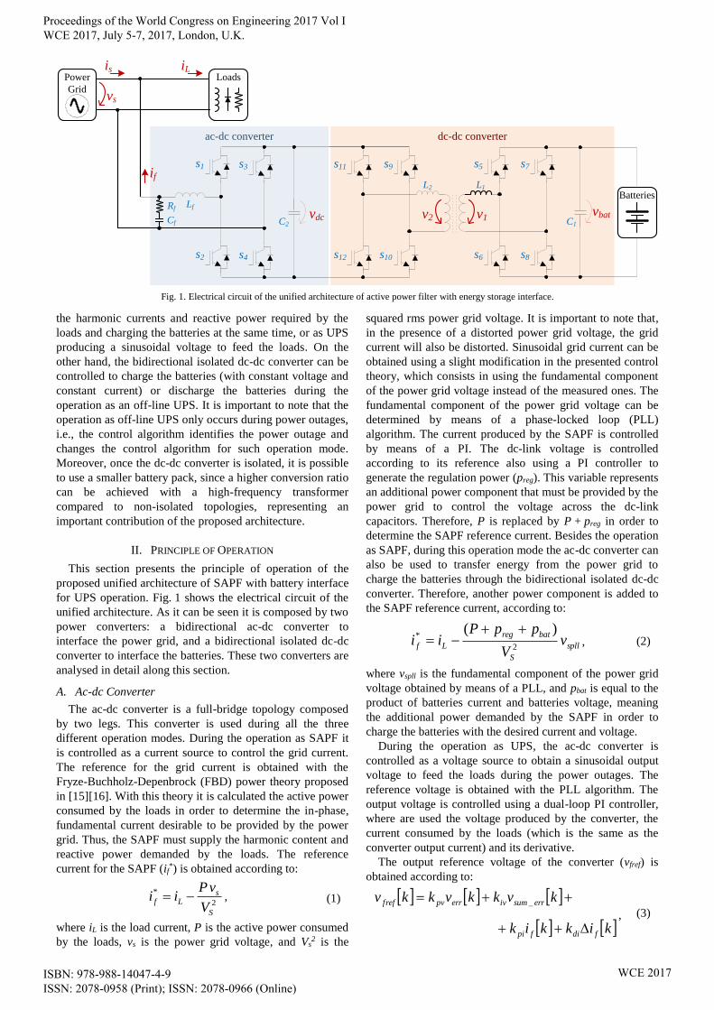
for UPS operation. Fig. 1 shows the electrical circuit of the
unified architecture. As it can be seen it is composed by two
power converters: a bidirectional ac-dc converter to
interface the power grid, and a bidirectional isolated dc-dc
converter to interface the batteries. These two converters are
analysed in detail along this section.
A. Ac-dc Converter
The ac-dc converter is a full-bridge topology composed
by two legs. This converter is used during all the three
different operation modes. During the operation as SAPF it
is controlled as a current source to control the grid current.
The reference for the grid current is obtained with the
Fryze-Buchholz-Depenbrock (FBD) power theory proposed
in [15][16]. With this theory it is calculated the active power
consumed by the loads in order to determine the in-phase,
fundamental current desirable to be provided by the power
grid. Thus, the SAPF must supply the harmonic content and
reactive power demanded by the loads. The reference
current for the SAPF (if*) is obtained according to:
2
*
S
sLf
V
vPii , (1)
where iL is the load current, P is the active power consumed
by the loads, vs is the power grid voltage, and Vs2 is the
squared rms power grid voltage. It is important to note that,
in the presence of a distorted power grid voltage, the grid
current will also be distorted. Sinusoidal grid current can be
obtained using a slight modification in the presented control
theory, which consists in using the fundamental component
of the power grid voltage instead of the measured ones. The
fundamental component of the power grid voltage can be
determined by means of a phase-locked loop (PLL)
algorithm. The current produced by the SAPF is controlled
by means of a PI. The dc-link voltage is controlled
according to its reference also using a PI controller to
generate the regulation power (preg). This variable represents
an additional power component that must be provided by the
power grid to control the voltage across the dc-link
capacitors. Therefore, P is replaced by P + preg in order to
determine the SAPF reference current. Besides the operation
as SAPF, during this operation mode the ac-dc converter can
also be used to transfer energy from the power grid to
charge the batteries through the bidirectional isolated dc-dc
converter. Therefore, another power component is added to
the SAPF reference current, according to:
spll
S
batreg
Lf vV
ppPii
2
*)(
, (2)
where vspll is the fundamental component of the power grid
voltage obtained by means of a PLL, and pbat is equal to the
product of batteries current and batteries voltage, meaning
the additional power demanded by the SAPF in order to
charge the batteries with the desired current and voltage.
During the operation as UPS, the ac-dc converter is
controlled as a voltage source to obtain a sinusoidal output
voltage to feed the loads during the power outages. The
reference voltage is obtained with the PLL algorithm. The
output voltage is controlled using a dual-loop PI controller,
where are used the voltage produced by the converter, the
current consumed by the loads (which is the same as the
converter output current) and its derivative.
The output reference voltage of the converter (vfref) is
obtained according to:
kikkik
kvkkvkkv
fdifpi
errsumiverrpvfref
_
, (3)
s2
s1
C2
vdc
s4
s3
s12
s11
s10
s9
s6
s5
s8
s7
C1
vbat
Power
Grid
Loads
BatteriesLfRf
Cf
L2 L1
v1v2
ac-dc converter dc-dc converter
is iL
if
vs
Fig. 1. Electrical circuit of the unified architecture of active power filter with energy storage interface.
Proceedings of the World Congress on Engineering 2017 Vol I WCE 2017, July 5-7, 2017, London, U.K.
ISBN: 978-988-14047-4-9 ISSN: 2078-0958 (Print); ISSN: 2078-0966 (Online)
WCE 2017
where verr is the output voltage error, vsumerr is the output
voltage error sum, if is the output current, Ts is the sampling
period and kxx are controller gains, where the first index (p, i
or d) means the controller component (proportional, integral
or derivative) and the second index (v or i) represents
voltage or current quantities. The output current derivative
Δif is determined according to:
S
ff
fT
kikiki
1 . (4)
In the scope of this paper, it was used a PI controller for the
output voltage and a proportional-derivative (PD) controller
for the output current in order to achieve a suitable
performance in the presence of nonlinear loads.
B. Bidirectional Isolated dc-dc Converter
The dc-dc converter consists in a voltage-fed
dual-active-bridge topology, where the primary side is the
low-voltage side and is connected to the batteries and the
secondary side is the high-voltage side, sharing the dc-link
with the ac-dc converter. Both sides are connected by a
high-frequency transformer, allowing isolation and a high
voltage conversion ratio.
The dual-active-bridge topology can be operated using
modulation techniques like pulse-width modulation (PWM),
phase shift and deviations from the latter. Phase shift [17]
allows a flexible power transfer between both sides of the
converter, being one of the most popular modulation
techniques applied to isolated dc-dc converters, such the
presented topology. Each side of the converter produces a
50% duty-cycle square-wave, being applied a phase shift
between both voltages. The applied phase angle has direct
impact in the transferred power, with the latter increasing
with the phase shift. Besides, phase shift modulation allows
active rectification, as opposed to PWM, where one
converter side is switched at each time. When low voltage
values are involved, the latter brings a reduced efficiency
due to the voltage drops on the output antiparallel diodes
[18]. Despite the aforementioned advantages, however,
phase shift modulation is not suitable when the voltages
applied to the transformer windings are discrepant with
respect to transformer turns ratio. This situation leads to
substantial currents in the transformer, as well as in the
power switches, even if the transferred power is low. Thus,
the converter operates with high values of reactive power.
To overcome this issue, variants of the phase shift
modulation technique were developed, e.g., dual phase shift
[19] and triple phase shift [20]. These modulation
techniques apply, respectively, two or three distinct phase
angles to the converter, using a phase difference between
two legs of the same bridge. Thus, circulating currents and
consequently reactive power can be reduced using these
modulation techniques. In addition, both PWM and phase
shift modulation techniques can be combined in order to
reduce the reactive power involved [21]. Therefore, a phase
shift modulation technique combined with duty-cycle
control was implemented for power transfer, reducing the
current stress in the switches and transformer windings. The
duty-cycle value is obtained with a PI controller, generating
high values of duty-cycle when the dc side converter
voltages have a close relationship in respect with the
transformer turns ratio and low values of duty-cycle for the
opposite case. The phase angle is obtained also by means of
a PI controller and is responsible for dc-link voltage
regulation when the system is operating in UPS mode and
controls the charging of the batteries when the system
operates as SAPF.
III. DEVELOPED PROTOTYPE
This section shows in detail the developed laboratorial
prototype, mainly focusing the digital control structure and
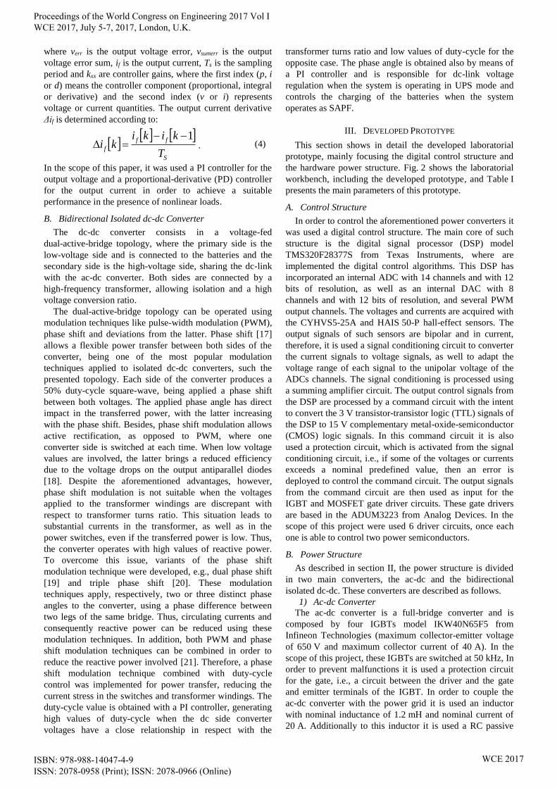
the hardware power structure. Fig. 2 shows the laboratorial
workbench, including the developed prototype, and Table I
presents the main parameters of this prototype.
A. Control Structure
In order to control the aforementioned power converters it
was used a digital control structure. The main core of such
structure is the digital signal processor (DSP) model
TMS320F28377S from Texas Instruments, where are
implemented the digital control algorithms. This DSP has
incorporated an internal ADC with 14 channels and with 12
bits of resolution, as well as an internal DAC with 8
channels and with 12 bits of resolution, and several PWM
output channels. The voltages and currents are acquired with
the CYHVS5-25A and HAIS 50-P hall-effect sensors. The
output signals of such sensors are bipolar and in current,
therefore, it is used a signal conditioning circuit to converter
the current signals to voltage signals, as well to adapt the
voltage range of each signal to the unipolar voltage of the
ADCs channels. The signal conditioning is processed using
a summing amplifier circuit. The output control signals from
the DSP are processed by a command circuit with the intent
to convert the 3 V transistor-transistor logic (TTL) signals of
the DSP to 15 V complementary metal-oxide-semiconductor
(CMOS) logic signals. In this command circuit it is also
used a protection circuit, which is activated from the signal
conditioning circuit, i.e., if some of the voltages or currents
exceeds a nominal predefined value, then an error is
deployed to control the command circuit. The output signals
from the command circuit are then used as input for the
IGBT and MOSFET gate driver circuits. These gate drivers
are based in the ADUM3223 from Analog Devices. In the
scope of this project were used 6 driver circuits, once each
one is able to control two power semiconductors.
B. Power Structure
As described in section II, the power structure is divided
in two main converters, the ac-dc and the bidirectional
isolated dc-dc. These converters are described as follows.
1) Ac-dc Converter
The ac-dc converter is a full-bridge converter and is
composed by four IGBTs model IKW40N65F5 from
Infineon Technologies (maximum collector-emitter voltage
of 650 V and maximum collector current of 40 A). In the
scope of this project, these IGBTs are switched at 50 kHz, In
order to prevent malfunctions it is used a protection circuit
for the gate, i.e., a circuit between the driver and the gate
and emitter terminals of the IGBT. In order to couple the
ac-dc converter with the power grid it is used an inductor
with nominal inductance of 1.2 mH and nominal current of
20 A. Additionally to this inductor it is used a RC passive
Proceedings of the World Congress on Engineering 2017 Vol I WCE 2017, July 5-7, 2017, London, U.K.
ISBN: 978-988-14047-4-9 ISSN: 2078-0958 (Print); ISSN: 2078-0966 (Online)
WCE 2017
filter with a capacitance of 10 µF and resistance of 8 Ω. The
8 Ω resistor is applied with the purpose of damp possible
resonances between the capacitive and inductive elements of
the passive filter. For the dc-link are used four capacitors
model MAL209527821E3 from Vishay in order to perform
a nominal capacitance of 3.28 mF with a maximum voltage
of 450 V.
2) Bidirectional Isolated dc-dc Converter
The dc-dc converter is a dual-active-bridge dc-dc
converter composed by four MOSFETs model
PSMN015-60PS from NXP Semiconductor (maximum
drain-source voltage of 60 V, maximum drain current of
50 A, and drain-source on-resistance of 14.8 mΩ) and four
MOSFETs model IPP50R500CE from Infineon
Technologies (maximum drain-source voltage of 500 V,
maximum drain current of 11 A and drain-source
on-resistance of 500 mΩ). In the scope of this project, these
MOSFETs are switched at 100 kHz, and, similarly to the
IGBTs of the ac-dc converter, it is used a protection circuit
for the gate, i.e., a circuit between the driver and the gate
and source terminals of the semiconductor. In the batteries
side it is used a capacitor with nominal capacitance of
4.7 mF and nominal voltage of 63 V. The galvanic isolation
between the primary and secondary converters is performed
using a 1:15 high-frequency transformer specially developed
for this project using ferrites model B66397G0000X187
from Epcos. The primary nominal current is 45 A (were
used 59 AWG25 wires in parallel) and the secondary
nominal current is 3 A (were used 3 AWG23 wires in
parallel).
IV. EXPERIMENTAL VALIDATION
This section presents the main experimental results
obtained to prove the proper operation of the proposed
unified architecture and to highlight its main benefits.
Therefore, this section is divided in three distinct modes of
operation: SAPF; UPS; and energy storage system.
A. Operation as SAPF
This item presents the operation of the proposed unified
architecture during the operation as SAPF. The first process
of this operation mode is the synchronization with the
fundamental component of the power grid voltage, where is
used the phase-locked loop (PLL) algorithm proposed
in [22]. After that, considering the current consumed by the
loads connected in the same electrical installation, it is
determined the reference current that the converter must
produce in order to obtain a sinusoidal grid current. The
details about the determination of the grid reference current
are presented in section II (a).
Fig. 3 shows the experimental results obtained with the
developed laboratory prototype during the operation as
SAPF. In this figure it is possible to see the power grid
voltage (vs), the load current (iL), which is the grid current
(is), the dc-link voltage (vdc), and the converter current
reference (ic*) calculated by the DSP. From this figure it is
possible to see that the current consumed by the loads (iL)
has a high harmonic distortion and, consequently, to cancel
such harmonic distortion, the determined converter current
reference (ic*) has also a high harmonic distortion. In this
experimental result, it is important to note that the dc-link
voltage is not yet controlled to its reference, i.e., the
converter only determines the reference current and is not
yet compensating the currents.
Fig. 4 shows the power grid voltage (vs), the grid current
(is), and the dc-link voltage (vdc) during the operation as
SAPF. As it can be seen, due to this operation mode, the
grid current (is) is sinusoidal with reduced harmonic
distortion (THD% = 3.6%), and in phase with the power
grid voltage (vs), i.e., from power grid point of view, the
electrical installation only operates with fundamental active
power. It is also important to note that the dc-link voltage is
regulated to the reference value, maintaining a proper value
in order to allow the accurate operation of the SAPF.
B. Operation as UPS
This item presents the operation of the proposed unified
architecture during the operation as UPS. This operation
mode only occurs during power outages, when control
changes, so that the ac-dc converter stops operating as
SAPF, and begins to produce a sinusoidal voltage to feed the
electrical loads. Therefore, the first algorithm is the
detection of power outages. For such purpose it was used the
half-cycle rms value of the power grid voltage to detect
when it falls below a threshold of 10% of the nominal value.
Fig. 5 shows the power grid voltage (vs), the rms value of
the power grid voltage (Vs) and a flag used to indicate when
DSP and Control
Board
Driver
Boards
Power
Converters
Input
Inductor
Hall-Effect
Sensors
Dc-link
Capacitors
High-Frequency
Transformer
Fig. 2. Laboratorial workbench with the developed prototype.
Table I. Main parameters of the developed prototype.
Parameter Value
Power Grid Voltage 230 V
Power Grid Frequency 50 Hz
Maximum Grid Current 16 A
Dc-link Voltage 400 V
Switching Frequency (ac-dc) 50 kHz
Switching Frequency (dc-dc) 100 kHz
High-Frequency Transformer Ratio 1:15
Maximum Power as UPS 1 kW
Batteries Voltage 23 V to 29 V
Batteries Current 40 A
Proceedings of the World Congress on Engineering 2017 Vol I WCE 2017, July 5-7, 2017, London, U.K.
ISBN: 978-988-14047-4-9 ISSN: 2078-0958 (Print); ISSN: 2078-0966 (Online)
WCE 2017
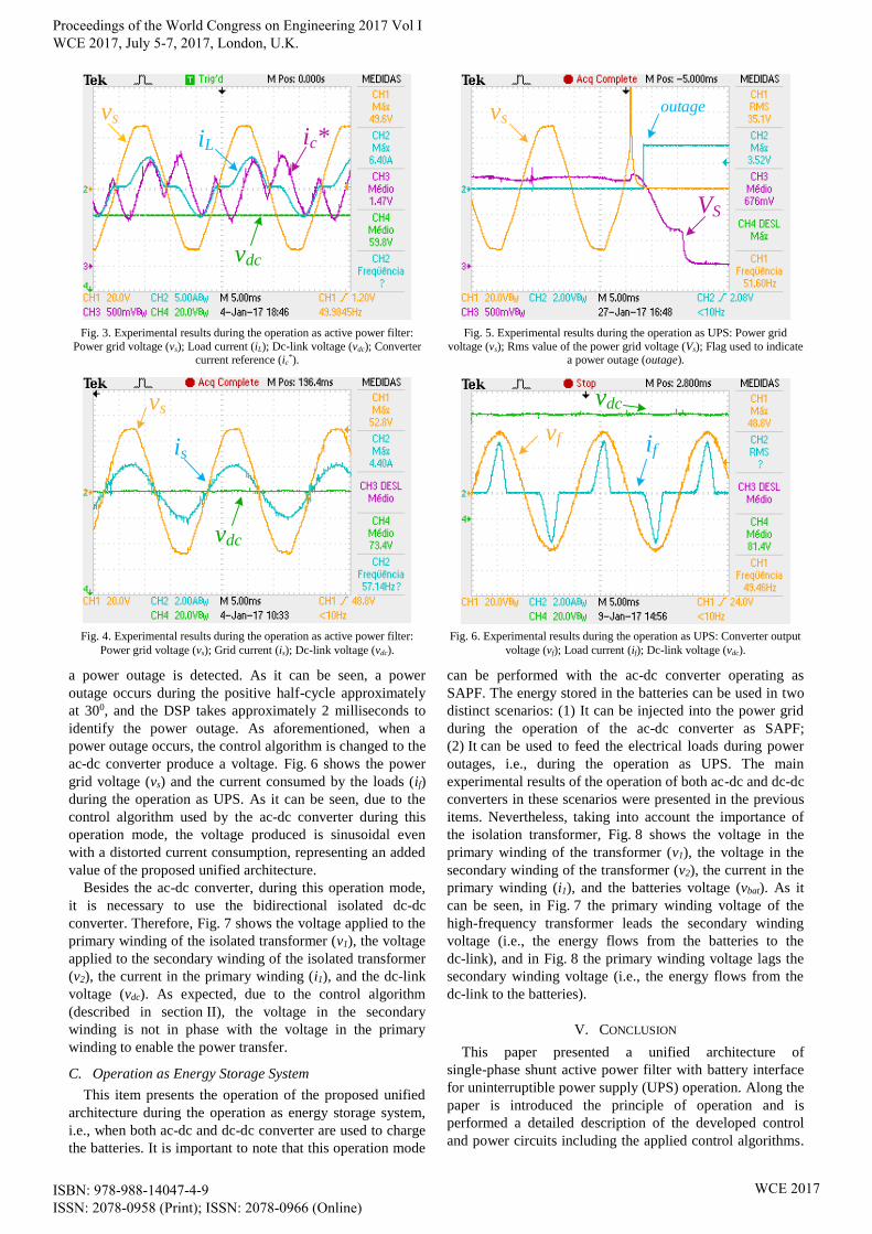
a power outage is detected. As it can be seen, a power
outage occurs during the positive half-cycle approximately
at 300, and the DSP takes approximately 2 milliseconds to
identify the power outage. As aforementioned, when a
power outage occurs, the control algorithm is changed to the
ac-dc converter produce a voltage. Fig. 6 shows the power
grid voltage (vs) and the current consumed by the loads (if)
during the operation as UPS. As it can be seen, due to the
control algorithm used by the ac-dc converter during this
operation mode, the voltage produced is sinusoidal even
with a distorted current consumption, representing an added
value of the proposed unified architecture.
Besides the ac-dc converter, during this operation mode,
it is necessary to use the bidirectional isolated dc-dc
converter. Therefore, Fig. 7 shows the voltage applied to the
primary winding of the isolated transformer (v1), the voltage
applied to the secondary winding of the isolated transformer
(v2), the current in the primary winding (i1), and the dc-link
voltage (vdc). As expected, due to the control algorithm
(described in section II), the voltage in the secondary
winding is not in phase with the voltage in the primary
winding to enable the power transfer.
C. Operation as Energy Storage System
This item presents the operation of the proposed unified
architecture during the operation as energy storage system,
i.e., when both ac-dc and dc-dc converter are used to charge
the batteries. It is important to note that this operation mode
can be performed with the ac-dc converter operating as
SAPF. The energy stored in the batteries can be used in two
distinct scenarios: (1) It can be injected into the power grid
during the operation of the ac-dc converter as SAPF;
(2) It can be used to feed the electrical loads during power
outages, i.e., during the operation as UPS. The main
experimental results of the operation of both ac-dc and dc-dc
converters in these scenarios were presented in the previous
items. Nevertheless, taking into account the importance of
the isolation transformer, Fig. 8 shows the voltage in the
primary winding of the transformer (v1), the voltage in the
secondary winding of the transformer (v2), the current in the
primary winding (i1), and the batteries voltage (vbat). As it
can be seen, in Fig. 7 the primary winding voltage of the
high-frequency transformer leads the secondary winding
voltage (i.e., the energy flows from the batteries to the
dc-link), and in Fig. 8 the primary winding voltage lags the
secondary winding voltage (i.e., the energy flows from the
dc-link to the batteries).
V. CONCLUSION
This paper presented a unified architecture of
single-phase shunt active power filter with battery interface
for uninterruptible power supply (UPS) operation. Along the
paper is introduced the principle of operation and is
performed a detailed description of the developed control
and power circuits including the applied control algorithms.
vs
ic*iL
vdc
Fig. 3. Experimental results during the operation as active power filter:
Power grid voltage (vs); Load current (iL); Dc-link voltage (vdc); Converter current reference (ic
*).
vs
is
vdc
Fig. 4. Experimental results during the operation as active power filter:
Power grid voltage (vs); Grid current (is); Dc-link voltage (vdc).
vs
VS
outage
Fig. 5. Experimental results during the operation as UPS: Power grid
voltage (vs); Rms value of the power grid voltage (Vs); Flag used to indicate a power outage (outage).
vf if
vdc
Fig. 6. Experimental results during the operation as UPS: Converter output
voltage (vf); Load current (if); Dc-link voltage (vdc).
Proceedings of the World Congress on Engineering 2017 Vol I WCE 2017, July 5-7, 2017, London, U.K.
ISBN: 978-988-14047-4-9 ISSN: 2078-0958 (Print); ISSN: 2078-0966 (Online)
WCE 2017
The experimental results were obtained to validate the
proposed integrated architecture and the control algorithms
through three distinct modes of operation: (1) Shunt active
power filter; (2) Isolated UPS to supply a set of priority
loads during power outages; (3) Energy storage system to
support the power grid. The proposed system can be an
optimal solution for single-phase installations, allowing the
compensation of power quality problems related with
current harmonics, power factor and power outages.
REFERENCES
[1] A. Araújo, J. G. Pinto, B. Exposto, C. Couto, and J. L. Afonso,
“Implementation and Comparison of Different Switching Techniques
for Shunt Active Power Filters,” IEEE IECON Industrial Electronics Society Conference, pp.1519-1525, Nov. 2014.
[2] Roger C. Dugan, Mark F. McGranaghan, S. Santoso, H. W. Beaty,
“Electrical Power Systems Quality,” McGraw-Hill (3rd Edition), pp. 373–435, 2002.
[3] H. Sasaki, T. Machida, “A new method to eliminate ac harmonic currents by magnetic flux compensation - considerations on basic
design,” IEEE Trans. Power App. Syst., vol.PAS-90, no.5, pp.2009-
2019, 1971. [4] J. G. Pinto, Bruno Exposto, Vitor Monteiro, L. F. C. Monteiro, Carlos
Couto, João L. Afonso, “Comparison of Current-Source and Voltage-
Source Shunt Active Power Filters for Harmonic Compensation and Reactive Power Control,” IEEE IECON Industrial Electronics Society
Conference, pp.5124-5129, Oct. 2012.
[5] L. Gyugyi, E. C. Strycula, “Active AC Power Filters,” IEEE IAS Industry Applications Society Annual Meeting, pp.529-535, 1976.
[6] H. Akagi, Y. Kanazawa, A. Nabae, “Instantaneous Reactive Power
Compensators Comprising Switching Devices without Energy Storage Components,” IEEE Trans. Ind. Appl., vol.IA-20, no.3, pp.625–630,
May 1984.
[7] B. Singh, K. Al-Haddad, and A. Chandra, “A Review of active filters for power quality improvement,” IEEE Trans. on Ind. Electron.,
vol.46, no.5, pp.960–971, Oct. 1999.
[8] Neil Hodge, “Energy Risks - the dangers of power cuts and blackouts,” Emerging Risks (Allianz), pp.28-33, 2015.
[9] Healthcare & Public Health Sector Coordinating Councils, “Planning
for Power Outages: A Guide for Hospitals and Healthcare Facilities,” 2003.
[10] J. P. Beaudet, J. N. Fiorina, and O. Pinon, “UPS topologies and
standards,” MGE-UPS Systems, 1999. [11] A. Emadi, A. Nasiri, and S. B. Bekiarov, Uninterruptible Power
Supplies and Active Filters. CRC Press, 2005.
[12] V. John and N. Mohan, “Standby power supply with high frequency isolation,” IEEE APEC Applied Power Electronics Conference and
Exposition, pp.990–994, Mar. 1995.
[13] Chi Zhang, Josep M. Guerrero, Juan C. Vasquez, “A simplified control architecture for three-phase inverters in modular UPS
application with shunt active power filter embedded,” ECCE
International Conference on Power Electronics, pp.413–420, June
2015.
[14] Bruno Exposto, J. G. Pinto, H. Goncalves, Vitor Monteiro, D.
Pedrosa, C. Couto, J. L. Afonso, “Evaluation of a Shunt Active Power Filter with energy backup capability,” IEEE IECON Industrial
Electronics Conference, pp.5963–5968, Nov. 2013. [15] M. Depenbrock, “The FBD-method, a generally applicable tool for
analyzing power relations,” IEEE Trans. Power Syst., vol.8, no.2,
pp.381–387, May 1993. [16] Telmo Santos, J. G. Pinto, P. Neves, D. Gonçalves, João L. Afonso,
“Comparison of Three Control Theories for Single-Phase Active
Power Filters,” IEEE IECON Industrial Electronics Society Conference, Nov. 2009.
[17] R. W. A. A. De Doncker, D. M. Divan, M. H. Kheraluwala, “A
Three-Phase Soft-Switched High-Power-Density DC/DC Converter for High-Power Applications,” IEEE Trans. Ind. Appl., vol.27, no.1,
pp.63–73, Jan. 1991.
[18] J. Sebastian, J. A. Cobos, O. Garcia, J. Uceda, “An overall study of the half-bridge complementary-control DC-to-DC converter,” IEEE
PESC Power Electronics Specialist Conference, vol.2, pp.1229-1235,
June 1995.
[19] Hua Bai, Chris Mi, “Eliminate Reactive Power and Increase System
Efficiency of Isolated Bidirectional Dual-Active-Bridge DC–DC
Converters Using Novel Dual-Phase-Shift Control,” IEEE Trans. Power Electron., vol.23, no.6, pp.2905–2914, Dec. 2008.
[20] Kuiyuan Wu, Clarence W. de Silva, William G. Dunford, “Stability
analysis of isolated bidirectional dual active full-bridge DC-DC converter with triple phase-shift control,” IEEE Trans. Power
Electron., vol.27, no.4, pp.2007–2017, Apr. 2012.
[21] Dehong Xu, Chuanhong Zhao, Haifeng Fan, “A PWM plus phase-shift control bidirectional dc-dc converter,” IEEE Trans. Power
Electron., vol.19, no.3, pp.666–675, May 2004.
[22] M. Karimi-Ghartemani, M. R. Iravani, “A new phase-locked loop (PLL) system,” IEEE MWSCAS Midwest Symposium on Circuits
and Systems, vol.1, pp.421–424, Aug. 2001.
vdcv1
i1
v2
Fig. 7. Experimental results during the operation as UPS: Voltage in the
primary winding of the transformer (v1); Voltage in the secondary winding
of the transformer (v2); Current in the primary winding (i1);
Dc-link voltage (vdc).
vbatv1
i1
v2
Fig. 8. Experimental results during the operation as energy storage system:
Voltage in the primary winding of the transformer (v1); Voltage in the
secondary winding of the transformer (v2);
Current in the primary winding (i1); Batteries voltage (vbat).
Proceedings of the World Congress on Engineering 2017 Vol I WCE 2017, July 5-7, 2017, London, U.K.
ISBN: 978-988-14047-4-9 ISSN: 2078-0958 (Print); ISSN: 2078-0966 (Online)
WCE 2017


![Hernan Ochoa - WCE Internals [RootedCON 2011]](https://img.pdfslide.net/doc/110x75/54827d4cb47959d80c8b479e/hernan-ochoa-wce-internals-rootedcon-2011.jpg)