Embed Size (px)
Citation preview

STUDY REPORTCAA-SR-89-21
wDESIGN FOR DISCARD (DFD) STUDY00
'mm
NJULY 1989
I
~DTT
DEC 12 i
PREPARED BY
OFFICE OF THE SPECIAL ASSISTANTFOR MODEL VALIDATIOnIN
US ARMY CONCEPTS ANALYSIS AGENCY8120 WOODMONT AVENUE
BETHESDA, MARYLAND 20814-2797
"DI ioTr--T rT L 1,eNT AAppevd r ubc reeaseA-" r! -:: 'c a! i

DISCLAIMER
The findings of this report are not to be const. ued as anofficial Department of the Army position, policy, or decisionunless so designated by other official documentation.Comments or suggestions should be addressed to:
DirectorUS Army Concepts Analysis AgencyATTN: CSCA ..MV8120 Woodmont AvenueBethesda, MD 20814-2797

CAA-SR-89-21
UNCLASSIFIEDSECURITY CLASSIFICATION OF THIS PAGE
Form App~roved
REPORT DOCUMENTATION PAGE OMBNo74-0188
Ia. REPORT SECURITY CLASSIFICATION I b. RESTRICTIVE MARKINGS
UNCLASSIFIED None2a SECURITY CLASSIFICATION AUTHORITY 3. DISTRIBUTION/AVAILABILITY OF REPORT
2b DECLASSIFICATION/OWNGRADING SCHEDULE Unlimited
1. PERFORMING PO TDRT NUMER(S) MONITORING RORGANeaIO MORT NUMBER 'SN
6a. NAME OF PERFORMING ORGANIZATION 6b OFFICE SYMBOL 7a NAME OF MONITORING ORGANIZAION
US Army Concepts Analysis (ifaPplicable) US Army Materiel Command (AMCRE-C)Agency ICSCA-MVD
6c. ADDRESS (City, State, and ZIP Code) 7b ADDRESS (City, State, and ZIP Code)8120 oodmont Avenue 5001 Eisenhower Avenue(ethesda, MD 20814-2797 Alexandria, VA 22333
Ba. NAME OF FUNDINGdSPONSORING 8b. OFFICE SYMBOL '9. PROCUREMENT INSTRUMENT IDENTIFICATION NUMBER
ORGANi S Army Materiel (ifapplicable)
Command iAMCRE-Cr. ADDRESS (City, State, and ZP Code) 10. SOURCE OF FUNDING NUMBERS
5001 Eisenhower Avenue PROGRAM PROJECT TASK WORKUNITAlexandria, VA 22333 ELEMENT NO INO NO ACCESSION NO
11. TITLE (include Security C Cassificationd
Design for Discard Study (UNCLASSIFIED)12. PERSONAL AUTHOR(S)Allison, Julianne, Study Director
13a. TYPE OF REPORT 13b. TIMECOVERED 14 DATEOFREPORT (Year, Month, Day) 15. PAGE COUNTStudy Report FROM N89 TO 29 890831 76
16. SUPPL.. MENTARY NOTATION
17F COSATI CODES 18. SUBJECT TERMS (Continue on reverse fnecessary and identify by block number)
FIELD GROUP SUB-GROUP Total Army Analysis; logistics support; force structure
1 9 ABSTRAT (Continue on revere if necessary and identify by block number)
The reason for performing the study was to determine the impact of the Design for Discard(DFD) concept on the Army's current Maintenance support force structure. DFD is an Armyinitiative to reduce materiel maintenance requirements by focusing on discard of systemcomponents in lieu of fault isolation and repair, i.e., an effort to identify parts whichcost more to repair than to replace. The study addressed those items currently coded forrepair which could be candidates for discard, using criteria and an economic methodologydeveloped by the US Army Materiel Systems Analysis Activity (AMSAA). Revised annual main-tenance manhours for those items meeting the criteria were applied against the currentManpower Requirements Criteria (MARC). The Force Analysis Simulation of Theater Admin-istrative and Logistic Support (FASTALS) Model was the tool used to assess the impact onforce structure of the reductions in manhours due to DFD. ,
20 DISTRIBUTION/AVAILABILITY OF ABSTRA(TT 217ABSTRACT. SECURITY CLASS,, Z.TIONI' UNCLASS;F!EO/!JNLIMITED C] SAME AS RPT []OTIC jSEPS UNCLASSIFIED
-2a NAME OF RESPONSIBLE ;NDIVIDUAL 12b TELEPHONE(include Area Cocie) 22, O CE SYFVBOLMr. Richard Callan (202) 274-9760 AMCRE-E
DO Form 1473, JUN 86 Previous editions Are obsolete. -: " . S C " 3 - ;,
UNC LASS IF "ED
STUDY REPORTCAA-SR-89-21
DESIGN FOR DISCARD (DFD) STUDY
July 1989 _Acession !orNTIS GRA&I
DTIC TABUnannounced ElJust ific"It i. 1
• By
.Dist i c:' - -
Avll it'" Codes............. .........::./Or
Prepared by
OFFICE OF THE SPECIAL ASSISTANT FOR MODEL VALIDATION
US Army Concepts Analysis AgencyI ( UCUwlu, Av v#aut
Bethesda, Maryland 20814-2797

CAA-SR-89-21
DEPARTMENT OF THE ARMY ." ,US ARMY CONCEPTS ANALYSIS AGENCY
8120 WOODMONT AVENUEBETHESDA, MARYLAND 20814-2797
RE PLY TO .
AflENTION OF
CSCA-MVD (5-5d) 0 6 NOV nqp
MEMORANDUM FOR U.S. Army Materiel Command, 5001 Eisenhower Av,r,,i,ATTN: AMCRE-C, Alexandria, VA 22333-0001
SUBJECT: Design for Discard (DFD) Study
1. Reference:
a. Verbal Request for Analytical Support (CAA Form 233), 31 '-vsubject: Design for Discard (DFD).
b. Memorandum, USACAA, CSCA-MVD, 27 Sep 89, subject: Design lorDiscard Study for Sponsor Review.
c. Memorandum, AMC, AMCRE-C, 11 Oct 89, subject: Design fo" i111-;'.Study for Sponsor Review.
2. Reference la requested that the U.S. Army Concepts Analysis Agency (L,.provide an assessment of the impacts of UFD on the Army's force structure etthe detail, i.e., Military Occupational Specialty and Table of Organiztio.,and Equipment, level.
3. This final report documents the results of our evaluation.
4. This Agency expresses appreciation to all commands and agencies ',Ki.have contributed to this study. Questions and/or inquiries should bedirected to the Office of the Special Assistant for Model Vali(;i;i ,o"Army Concepts Analysis Agency, 8120 Woodmont Avenue, Bethesda, 'I20814-2797, AUTOVON 295-5225.
E. B. VANDIVER IIIDirector
iii

hNtJ DESIGN FOR DISCARD (DFD) STUDYClAA~
STUDY SUMMARYCAA CAA-SR-89-21
THE REASON FOR PERFORMING THE STUDY was to determine the impact of theDesign for Discard (DFD) concept on the Army's force structure. DFD is anArmy initiative to reduce materiel maintenance requirements by focusing ondiscard of system components in lieu of fault isolation and repair. It is aneffort to identify parts which cost more to repair than to replace. The goalis to design or select system components which are easily diagnosed andisolated upon failure and, if possible, inexpensive enough to throw away atfailure. The resultant avoidance of maintenance allows personnel spaces tobe realigned or converted to other military occupational specialties (MOSs)and applied against force structure shortfalls.
THE STUDY SPONSOR was the US Army Materiel Command (AMC), AMCRE-C.
THE STUDY OBJECTIVE was to determine the force structure impact of the DFOconcept on current Army maintenance support requirements.
THE SCOPE OFTHE STUDY was as follows:
(1) The DFD Study was based on the Defense Guidance (DG) IllustrativePlanning Scenario (IPS) and the 1996 Total Army Analysis (TAA)/Table ofOrganization and Equipment (TOE) Army.
(2) The study focused on the reparable components of 60 major end itemswhich constitute about 60 percent of the total maintenance workload estimatedusing Manpower Requirements Criteria (MARC) factors. Currently, MARC factorsaccount for only combat mission essential repairs of equipment, not includingany associated with combat damage.
(3) Only those components with maintenance tasks of repair, test, oroverhaul at the direct support (DS) and general support (GS) levels wereconsidered.
THE MAIN ASSUMPTIONS of this work are:
(1) The sample of major end items used in the study provides a reasonablebasis for an estimate of potential force structure savings which accrue fromdiscarding and replacing components due to reliability, availability, andmaintainability (RAM) failure in lieu of repair/overhaul of components.
(2) The leader MOS concept used in the Force Analysis Simulation ofTheater Administrative and Logistic Support (FASTALS) Model for determining
maintenance unit requirements still applies.
v

(3) Failure rates of components in wartime will not vary significantly
from peacetime experience.
(4) Estimates used in place of missing data elements were reasonable.
THE BASIC APPROACHES used in this study were to:
(1) Include those systems encompassing 60 percent of the DS and GSmaintenance workload.
(2) Focus on the component parts of these end items which are currentlycoded for repair Out cuuid become candidates for discard.
'3) Compare these items against criteria developed by the US ArmyMateriel Systems Analysis Activity (AMSAA).
(4) Apply reductions in workload factors for items meeting the criteria,using the FASTALS Model to determine potential force structure savings.Identify the savings, if any, in terms of military spaces by MOS and standardrequirement code (SRC).
THE PRINCIPAL FINDINGS of the work reported herein are as follows:
(1) Many components of major end items could be reclassified asdiscardable items based on the economic methodology used in the study.
(2) Force structure savings based on the labor savings achieved throughthe use of the DFD concept and applied through the study methodology werenegligible.
(3) Further study should be undertaken by the US Army Training andDoctrine Command (TRADOC), possibly to include replacement (versus repair) ofcomponents due to combat damage. No significant savings in force structurewill be realized through the use of the DFD concept unless the Army'smaintenance structure is realigned. Changes in unit design and allocationrules are necessary for the DFD concept to prove effective in reducingrequired force structure.
THE STUDY EFFORT was directed by Ms. Julianne Allison, CSCA-MVD, 295-5225.
COMMENTS AND QUESTIONS may be sent to the Director, US Army ConceptsAnalysis Agency, ATTN: CSCA-MV, 8120 Woodmont Avenue, Bethesda, Maryland20814-2797.
Tear-out copies of this synopsis are at back cover.
vi

CAA-SR-89-21
CONTENTS
CHAPTER Page
1 INTRODUCTION .. ... ...... ...... ..... ... 1-1
Background. .. ..... ...... .... . .......- 1DFD Study..... ... ..... ...... ........ 1-1Contents of theeport .. .... ..... ...... ... 1-3
2 DATA. .. ..... ...... ... .. .. .. .. .... 2-i
Data Request .. ... ...... ...... ..... ... 2-1Data Problems. .... ...... ..... ......... 2-1End Items.. ...... ...... ..... ........ 2-1Data Elements...... .... ..... ... ... 2-4Data Limitations . .. ........... ...... 2-6
3 METHODOLOGY. ... .... . ... ............. 3-1
Two-part Methodology... ........ ..... ....... 3-iEconomic Methodology .. .. .... .. .. .. .. .... 3-1Force Structure Methodology.... ...... ...... 3-3Sensitivity Analysis. ...... ......... ..... 3-6
4 RESULTS AND ANALYSIS.. ... .. ...... ...... 4-1
Introduction .. ... .. ......... ..... ... 4-1Labor Savings..... ...... ..... ...... .. 4-1Results of Base Case Runs................4-1Results of Constrained Base CaseRuns...... ...... 4-4Excursions . o.. .. .. ...... .. .. ...... 4-4Magnitude of Force Structure Savings .. .... ..... .. 4-9Answers to EEA....... ...... ..... .... 4-10Conclusions and Rec ommendations...............4-11
APPENDIX
A Study Contributors...................A-iB Candidates for Reclassification a s icadabl*e*1tems . B-iC Bibliography . . . . .. .oo. .. .. .. o. .. .. ... C-iD The FASTALS Model ... ..... ..... ...... .. 0-iE Distribution .. ... ..... ...... ..... ... E-1
GLOSSARY. .. ......... ...... ...... ..... Glossary-i
vii

CAA-SR-89-21
FIGURES
FIGURE Page
3-1 Economic Methodology .... .... ................... 3-23-2 Force Structure Methodology ... ... ................ 3-5
4-1 Results by Theater (unconstrained), Base Case andExcursions .... .... ........................ .. 4-9
0-1 FASTALS Logic Flow .... .. .. ..................... D-3
TABLES
TABLE
2-1 End Items ... 2-22-2 Task Record Data Eement................. 2-42-3 End Item Record Data Elements .... ............... .. 2-42-4 NSN Record Data Elements .... .. .................. .. 2-52-5 End Items Dropped from Study .... ................ ... 2-6
3-1 MIAl Tank Example ... ... ..................... ... 3-3
4-1 Labor Savings - Annual Maintenance Manhours .. ........ .. 4-24-2 Base Case Results - Unconstrained .... ............. ... 4-44-3 Base Case Results - Constrained. .... .. ............. 4-44-4 Labor Savings - Base Case vs Excursions ... .......... ... 4-54-5 Results of Excursion 1 - Unconstrained .. ........... .. 4-74-6 Results of Excursion 1 - Constrained.. .... ........... 4-74-7 Results of Excursion 2 - Unconstrained .. ........... .. 4-84-8 Results of Excursion 2 - Constrained .... .. ......... 4-84-9 Magnitude of Force Structure Savings (relative to
beginning strength) ... . ........ 4-104-10 Magnitude of Force Structure Savings (reiative to
beginning maintenance strength) .... ............ ... 4-10
viii

CAA-SR-89-21
DESIGN FOR DISCARD (DFD) STUDY
CHAPTER 1
INTRODUCTION
1-1. BACKGROUND
a. Design for Discard (DFD) Concept. Design for Discard (DFO) is an Armyinitiative to reduce materiel maintenance requirements by focusing on discardof system components in lieu of fault isolation and repair, i.e., an effortto identify parts which cost more to repair than to replace over the lifecycle of the system. The goal is to design or select system components whichare easily diagnosed and isolated upon failure and, if possible, inexpensiveenough to throw away at failure. The resultant avoidance of maintenancewould allow personnel spaces to be realigned or converted to other militaryoccupational specialties (MOSs) and applied against force structureshortfalls.
b. Previous DFD Studies. During 1987 and 1988, two macrolevel studieswere conducted to examine the DFD concept and its possible implications. In1987, the Inventory Research Office (IRO) of the US Army Materiel SystemsAnalysis Activity (AMSAA) completed a study entitled "Approximate Proceduresto Reevaluate Reparable Items' Costs for the Option Throwaway (The APRICOTAnalysis)." The study looked at the Army's catalog of current reparablecomponents for fielded end items to assess the impact of a DFD environment onthe current maintenance of items. The repair versus throwaway costs werecompared for items in the reparable catalogs. Estimated failure rates andaverage manhours and cost data were used. The findings showed potentiallysignificant savings in the form of dollars and manpower could be chieved byimplementation of the concept. However, further study was recommended toidentify these savings at a more detailed level. Army Materiel Command (AMC)commanding officers, after being briefed, requested analysis of specificsystems. A follow-on study was conducted in 1988 which focused on two majorend items, the M109 howitzer and the M939 truck series. Again, the potentialmanpower and dollar savings estimated in this study that would result fromreclassifying existing reparable components as throwaway for the two enditems studied were found to be significant. It ws then recommended that amicrolevel study be conducted to determine the impact of DFD on the Army'sforce structure.
1-2. DFD STUDY
a. Tasking. The US Army Concepts Analysis Agency (CAA) was tasked by AMCto conduct the recommended detail-level study. The DFD Study was planned tobe incorporated as an excursion to the Support Force Requirements AnalysisStudy - 1996 (SRA-96), CAA's part of the Total Army Analysis - 1996 (TAA-96)process. The study would include the top maintenance workload generators,i.e., those systems encompassing 50 percent of the direct support (DS) andgeneral support (GS) maintenance workload. The list of systems was expandedto include those making up 60 percent of DS and GS maintenance. This was
I-I

CAA-SR-89-21
done to allow for potential data problems and/or lack of data so that thesystems actually studied would make up at least 50 percent of the maintenanceworkload. Component parts of these end items which are currently coded forrepair but could become candidates for discard were the subject of the study.These items were to be compared against criteria developed by AMSAA. Foritems meeting the criteria, reductions in workload factors were to be appliedusing the Force Analysis Simulation of Theater Administrative and LogisticSupport (FASTALS) Model to determine potential force structure savings. Thesavings, if any, were to be identified in terms of military spacps (by MOS)and standard requirement code (SRC). These spaces could then be appliedtoward other combat service support (CSS) functions or combat/combat support(CS) spaces.
b. Purpose The purpose of the DFD Study was to determine the impact ofthe DFD concept on the Army's force structure.
c. Scope. The DFD Study was based on the Defense Guidance (DG) Illustra-tive Planning Scenario (IPS) and the 1996 TAA/Table of Organization andEquipment (TOE) Army. The study focused on the reparable components of 60major end items which constitute a large percentage (about 60 percent) of thetotal maintenance workload. Currently, MARC factors account for only combatmissien essential repairs of equipment, not including any associated withcombat damage. Only those components with maintenance tasks of repair, test,or overhaul at the DS and GS levels were .onsidered. (This is explained inChapter 3.) An economic criteria, projected lifetime replacement cost(PLRC), was used to determine which items were candidates for replacementrather than repair.
d. Essential Elements of Analysis (EEA). The EEA of the study were to:
(1) Identify existing reparable components for possible reclassifi-cation as throwaway components.
(2) Identify military spaces by MOS and SRC which could be realigned orconverted to other MOSs.
(3) Determine the impact on the Army force structure of the DFD conceptwithin the limits of the scope of this study.
The answers to these EEA, as determined in the DFD Study, are addressed inChapter 4, Results and Analysis.
e. Assumptions. The assumptions applicable to the DFD Study were asfollows:
(1) The sample of major end items used in the study orovides a reason-able basis for an estimate of potential force structure savings which accruefrom discarding and replacing components due to reliability, availability,and maintainability (RAM) failure in lieu of repair/overhaul of components.
(2) The leader MOS concept used in FASTALS for determining maintenanceunit requirements still applies.
1-2
CAA-SR-89-21
(3) Failurp rates of components in wartime will not vary significantlyfrom peacetime experience.
(4) Estimates used in place of missing data elements were reasonable(these eftimates are described in Chapter 2, paragraph 2-5, DataLimitations).
1-3. CONTENTS OF THE REPORT. This chapter has provided the introdictoryinformation applicable to the DFD Study. Following chapters contain moredetailed information concerning the data, methodology, and results of thestudy.
1-3

CAA-SR-89-21
CHAPTER 2
DATA
2-1. DATA REQUEST. In June of 1988, AMC put out a data call for the DFDStudy. The data request specifiedtherequired data elements and includedrecord format specifications for data on 60 major end items by line itemnumber (LIN). Each of AMC's major subordinate commands (MSCs) was requiredto provide the requested information for all reparable components by nationalstock number (NSN) of each end item managed by their command. The data wastc be provided in dBase III compatible floppy disk files. The suspense datefor submission of the data was I August 1988.
2-2. DATA PROBLEMS. Several problems were encountered with both thesubmission of data and the data itself. There were extensive delays inobtaining the data. The effort was not completed until February 1989. Thisforced the study to be separated from the SRA-96 Study, which it had origi-nally been planned to supplement as an excursion. The DFD Study was thentemporarily put on hold until March of 1989. When the study was resumed,several data problems were discovered. First, for some end items, no datawas provided at all. Secondly, much of the data that was provided was not inthe requested form. Most of it was provided on floppy disks as requested,but much of it was not in dBase III file format. Those that were not wereeither "flat" files (ASCII format) or in LOTUS 1-2-3 file format. The datanot provided on floppy disk were either in hard copy form or on tape.Thirdly, some of the data was not in the required data format, e.g., dataelements were not in the required fields, decimal formats were incorrect,etc. Lastly, there were many problems with missing or incomplete dataelements. Many of these problems were resolved through phone calls, fileconversion, and manipulation of the data files and the data, but some couldnot be resolv2d. Estimates were made for some of the data elements thatremained incomplete. The resolution of these problems caused more delays inconducting the study. Actual FASTALS production runs for the DFD Study beganin May 1989.
2-3. END ITEMS. At the outset of the DFD Study, it was decided thatfocusing on a small number of systemics would not accomplish the study objec-tives. It was also not feasible to study all end items with reparablecomponents, so a way of choosing the systems to be studied had to be deter-mined. The total maintenance workload was used as the criteria for choosingthe systems to be studied. The top 60 workload generators (out of a total of2,135), which comprise 60 percent of the total DS and GS maintenance work-load, were chosen. The end items studied and their associated LINs arelisted in Table 2-1, along with the MSC responsible for management of eachitem.
2-1

CAA-SR-89-21
Table 2-1. End Items(page 1 of 2 pages)
LIN LIN nomenclature MSC
C10908 CARRIER CARGO: TRACKED AMMO MEDIUM 7-TON TACOM
C12155 CARRIER PERSONNEL FULL TRACKED: ARMORED FIRE SPT TACOM
C76335 CAVALRY FIGHTING VEHICLE: M3 TACOM/AMCCOM
D11049 CARRIER CARGO: TRACKED 6-TON TACOM
Dl1538 CARRIER COMMAND POST: LIGHT TRACKED TACOM
D12087 CARRIER PERSONNEL FULL TRACKED: ARMORED TACOM
E00533 CHARGER RADIAC DETECTOR: PP-1578/PD CECOM
E56896 COMBAT VEHICLE ANTITANK: IMPROVED TOW VEH (W/O TOW WPN) TACOM
E70064 COMP UNIT RCP: TRK 2 WHL PNEU TIRES GAS DRVN 5 CFN 175 PSI TACOM
H02300 ELECTRONIC TELETYPEWRITER SECURITY EQUIPMENT: ISEC/KW-7 CECOM
J35813 GEN ST DSL ENG: 5KW 60HZ 1-3PH AC 120/208 120/240V TAC UTIL TACOM
J35825 GENSTDSLENG: 1OKW60HZ 1-3PHAC 120/208 120/240VTACUTIL TACOM
J42100 GEN STGAS ENG TM: 10KW 60HZ 1-3PH AC 120/240 120/208V PU-619/ TACOM
J43918 GEN ST GAS ENG: 1.5KW 60HZ 1PH 2 WIRE AC 120V SHOCK TAC UTIL TACOM
J44055 GEN ST GAS ENG: 1.5KW DC 28V SHOCK TAC UTIL TACOM
J45699 GEN ST GAS ENG: 3KW 60HZ 1-3PH 120/240 120/208V SKD TAC UTIL TACOM
J46110 GEN ST GAS ENG: 3KW DC 28V SKD-SHK TBLR FRAME MTD TAC UTIL TACOM
J47617 GEN ST GAS ENG TM: 5KW 60HZ 2EA MTD ON Ml 16 PU-260 TACOM
J81750 INFANTRY FIGHTING VEHICLE TACOM/AMCCOM
J95533 GUIDED MISSILE SYSTEM INTERCEPT AERIAL CARRIER MTD: (CHAP) MICOM
K29694 HEL ATTACK: TOW MISSILE AVSCOM
K31042 HEL OBSERVATION: OH-58A AVSCOM
K31795 HELUTILITY: UH-1H AVSCOM
K322-3 ;iEL UTILITY: UH-60A AVSCOM
K56981 HOWITZER HVY SELF-PROPELLED: 8 INCH AMCCOM
K57667 HOWITZER MED SELF-PROPELLED: 155 MM AMCCOM
P45003 POWER UNIT UTIL PACK: GAS TURBINE ENG DRVN (MUST) TACOM
Q90100 RADIO TELETYPEWRITER SET: AN/GRC-122 CECOM
Q9012C RADIO TELETYPEWRITER SET: AN/GRC-142 CECOM
R50544 RECOVERY VEH FULL TRACKED: LT ARMORED AMCCOM
R50681 RECOVERY VEHICLE FULL TRACKED: MEDIUM TACOM
R94977 RIFLE 5.56MM: M16A1 AMCCOM
T05028 TRUCK UTIL: TACTICAL 3/4 TON W/E M 1009 TACOM
2-2

CAA-SR-89-21
Table 2-1. End Items(page 2 of 2 pages)
LIN LIN nomenclature MSC
T07543 TRUCK UTIL: S250 SHELTER CARRIER 4X4 W/E (HMMWV) TACOM
T10138 SHOP EQUIP CONTACT MAINT TRK MTD AMCCOM
T13168 TANK COMBAT FULL TRACKED: 120MM GUN TACOM
T13169 TANK COMBAT FULL TRACKED: 105MMGUN(TTS) TACOM
T13374 TANK COMBAT FULL TRACKED: 105MM M1 (ABRAMS) TACOM
T34437 TRACTOR WHEELED: DSL 4X4 W/EXCAVATOR AND FRONT LOADER TACOM
T49119 TRUCK LIFT FORK: DSL DRVN 10000 LB CAP0 48-IN LD CTR ROUGH TACOMTERRAIN
T49255 TRUCK LIFT FORK: DSL DRVN 4000LB CAP ROUGH TERRAIN TACOM
T59346 TRUCK CARGO: TACT 5/4 TON 4X4 W/COMMO KIT TACOM
T59482 TRUCK CARGO: TACT 5/4 TON 4X4 W/E M 1008 TACOM
T61494 TRUCK UTIL: CARGO/TROOP CARRIER 1-1/4-TOW 4X4 W/E (HMMWV) TACOM
T92242 TRUCK UTIL: ARMT CARRIER ARMD 1-1/4-TON 4X4 W/E (HMMWV) TACOM
V12141 TANK & PUMP UNIT LIQ DISPENSING TRUCK MOUNTING TACOM
V31211 TELEPHONE SET: TA-312/PT CECOM
W76473 TRACTOR FULL TRACKED HIGH SPEED: ARMORED COMBAT TACOMEARTHMOVER
W95537 TRAILER CARGO: 3/4 -TON 2 WHEEL W/E TACOM
W95811 TRAILER CARGO: 1-1/2-TON 2 WHEEL W/E TACOM
X23277 TRANSPORTER BRIDGE FLOATING TACOM
X40009 TRUCK CARGO: 2-1/2-TON 6X6 W/E TACOM
X40146 TRUCK CARGO: 2-1/2-TON 6X6W/WINCH W/E TACOM
X40794 TRUCK CARGO: DROPSIDE 5TON 6X6W/E TACOM
X40831 TRUCK CA 0-%O: 5 TON 6X6 LWB W/E TACOM
X43708 TRUCK DUMP: 5-TON 6X6 W/E TACOM
X44403 TRUCK DUMP: 20-TON DSL DRVN 12 CU YD CAP (CCE) TACOM
X59326 TRUCK TRACTOR: 5-TON 6X6 W/E TACOM
X60833 TRUCK UTILITY: 1/4-TON 4X4 W/E TACOM
X63299 TRUCK WRECKER: 5-TON 6X6 W/WINCH WE TACOM
2 3

CAA-SR-89-21
2-4. DATA ELEMENTS. Three types of data records were required for each enditem. The following paragraphs discuss each record type and its dataelements.
a. Task Record. The first record type was the task record. Table 2-2
specifies the data elements included in each task record.
Table 2-2. Task Record Data Elements
Data element Data elementdescriptor
LIN Line item number of end item
NSN National stock number of reparable component
TASK Maintenance task performed on component: repair, replace,overhaul, test, adjust
ECH Echelon at which task performed: ORG, IDS, IGS, DEP
MOS Primary military occupational specialty code for task
HRM Manhours to perform task
NUMP Number of people required on task
IDEF Deferability of task: immediately (IMM), 1st opportunity
_ (FOP), indefinite (IND)
b. End Item Record. Table 2-3 lists the data elements in the end item
record.
Table 2-3. End Item Record Data Elements
Data element Data elementdescriptor
LIN Line item number of end item
NAME Nomenclature of end item
DENS Total density of all end items in LIN averaged to a per-year basis over projected lifetime
YRS Projected number of years remaining in life of end item
PCD Program code: M = mileage, R = rounds, H = hours, F =flying hours
PROG Projected average yearly usage pr)gram for all end itemsin LIN
BASE Base usage program upon which failure factors are computedfor all end items in LIN
2-4

CAA-SR-89-21
c. NSN Record. Within each LIN, there were several NSNs. The NSN recordincludes all data elements associated with each of the NSNs for one LIN. TheJata elements are listed in Table 2-4.
Table 2-4. NSN Record Data Elements
Dataelement Data element
descriptor
NSN National stock number of reparable component
NAME Nomenclature of reparable component
FF1 Failure factor for peacetime usage
FF2 Failure factor for wartime usage
PCD Program code: M = miles traveled, R = rounds fired, H =
hours operated, F = flying hours
UP Unit pricE
WGT Weight (pounds)
CUBE Volume (cubic feet)
MTD ORG Maintenance task distribution - organizational: per-centage of repair of this component conducted at ORG level
MTD IDS Maintenance task distribution - intermediate direct sup-port: percentage of repair of this component conducted atIDS level
MTD IGS Maintenance task distribution - intermediate generalsupport: percentage of repair of this component conductedat IGS level
MTD DEP Maintenance task distribution - depot: percentage ofrepair of this component conducted at DEP level
REPR Replacement factor - percentage of removal componentswhich cannot be repaired
FGC Functional group code assigned to group of NSNs to whichthis component belongs for purposes of MARC taskings
SMR Source, maintenance, and recoverability code
Note: from this point on in this report, the data element descriptors shownin the first column of Tables 2-2 through 2-4, rather than the entire dataelement name, will be used to refer to each data element.
2-5

CAA-SR-89-21
2-5. DATA LIMITATIONS
a. Reduction in Number of End Items Studied. As mentioned in paragraph2-2, some data problems were encountered at the outset of the DFD Study whichcould not be resolved. Data was incomplete or unusable for 14 end items.Therefore, the original list of 60 end items to be studied (which make up 60percent of the total maintenance workload) had to be reduced to 46. Those 46items constitute 48 percent of the total workload. Although this did notquite meet the goal of studying systems that make up 50 percent of theworkload, it was very close. The 14 end items that had to be dropped fromthe study were those shown in Table 2-5.
Table 2-5. End Items Dropped from Study
LIN LIN nomenclature
E00533 CHARGER RADIAC DETECTOR: PP-1578/PD
H02300 ELECTRONIC TELETYPEWRITER SECURITY EQUIPMENT: ISEC/KW-7
J95533 GUIDED MISSILE SYSTEM INTERCEPT AERIAL CARRIER MTD: (CHAP)
Q90100 RADIO TELETYPEWRITER SET: AN/GRC-122
Q90120 RADIO TELETYPEWRITER SET: AN/GRC-142
R50681 RECOVERY VEHICLE FULL TRACKED: MEDIUM
T10138 SHOP EQUIP CONTACT MAINT TRK MTD:
T34437 TRACTOR WHEELED: DSL 4X4 W/EXCAVATOR AND FRONT LOADER
T49119 TRUCK LIFT FORK: DSL DRVN 10000 LB CAP0 481N LD CTR ROUGH TERRAIN
V31211 TELEPHONE SET: TA-312/PT
W76473 TRACTOR FULL TRACKED HIGH SPEED: ARMORED COMBAT EARTHMOVER
W95537 TRAILER CARGO: 314 TON 2 WHEEL W/E
W95811 TRAILER CARGO: 1-1/2 TON 2 WHEEL W/E
X60833 TRUCK UTILITY: 1/4 TON 4X4 W/E
b. Data Estimates. It was stated in paragraph 2-2 that some dataelements were missing or questionable and had to be estimated. The followingparagraphs specify these elements and explain the estimates used.
(1) Data Element BASE. In almost all of the data files, the dataelement BASE was either missing or equal to the PROG element. Since thisproblem was so prevalnt, all missing BASE elements were also set equal totheir corresponding PROG elements. This effectively eliminated the use ofthese elements in the study because they were to be used in a formula wherePROG is divided by BASE and the result multiplied by other data elements.The result of the division would always be equal to one and the calculationwould have no effect on the result of the formula.
2-6

CAA-SR-89-21
(2) Data Element YRS. The data element YRS was missing in several datariles. In these cases, an estimate of 20 years was used.
(3) Data Element PCD. In a majority of the data files, the element PCDwas either missing or the same throughout the file. It was decided that thisdata was not useful as it was and that it was not feasible to try to recol-lect the data. Therefore, this data element was not used in the study.
c. Data Elements Not Used. There were several data elements that wereincluded in the data call which did not enter directly into study calcula-tions or analysis. Many of these elements were used implicitly, as they wereinherent in other elements. For example, NUMP is implicitly a part of theHRM. Also, the FASTAIS methodology and associated workloads provided a meansof estimating the impdct of DFO without the need for some of the requestedelements. The items not used explicitly in the study were the following:NUMP, IDEF, FF2, WGT, CUBE, MTD ORG, MTO IDS, MTD IGS, MTD DEP, REPR, FGC,and SMR.
2-7

CAA-SR-89-21
CHAPTER 3
METHODOLOGY
3-1. TWO-PART METHODOLOGY. There were two major parts to the methodologyused in the DFD Study. The first part, which will be referred to as theeconomic methodology, involved the calculations required to determine whethera component of an end item met the criteria to become a discardable item.The second part of the methodology was the force structure methodology. Thisinvolved the use of the FASTALS Model to assess the potential savings inforce structure due to the DFD concept. Both methodologies are discussed indetail in this chapter.
3-2. ECONOMIC METHODOLOGY
a. Data Processing. The first step in the study was to reconcile thedata. Since the data arrived in various file formats, one had to be chosenas the preferred format. LOTUS 1-2-3 was chosen, and all data that was notalready in LOTUS 1-2-3 format was converted. When this was finished, thereexisted three LOTUS files for each end item (LIN): a task file, an end itemfile, and an NSN file. These three files were aggregated for each LIN. Thiswas done by simply combining the end item file and the NSN file and thenmatching on NSN to incorporate the task file (the NSN appeared in both theNSN file and the task file). The next step was to reduce the number of NSNsto be considered as throwaway candidates by checking them against certaincriteria.
b. Echelon and Task Criteria. The first criteria against which eachcomponent was checked was the echelon criteria. Only those components whosetasks are performed at either the DS or GS echelon were used, since FASTALSdoes not directly consider maintenance tasks to be performed at organiza-tional or depot levels. Components meeting this test were then checked forthe types of tasks to be performed on them. Those with tasks of repair,test, or overhaul were chosen. The next step was to calculate the projectedlifetime replacement cost (PLRC) for each LIN/NSN combination. Thiscalculation is the subject of the following paragraph.
c. PLRC Calculation. The first part of the PLRC calculation is thecomputation of projected lifetime failures (PLF). The formula used tocompute PLF is as follows (using the data element descriptors that appearedin Tables 2-2 through 2-4):
PLF = FF1 * (PROG/BASE) * (DENSITY/100) * YRS
(In this formula, the PROG/BASE portion of the equation was effectivelyeliminated from the calculation because it was always equal to 1, asexplained in paragraph 2-5a.) To determine the PLRC, the PLF is thenmultiplied by the unit price (UP):
PLRC = PLF * UP
These formulas were provided to CAA for the DFD Study by IRO.
3-1
eellll I I i I I I m I I I I

CAA-SR-89-21
d. Economic Criteria. The PLRC is the criteria used to separate repar-able components into potential discard candidates and those with prohibitivecosts which would remain reparable items. IRO provided, a cutoff point of$500,000 to be used as the factor to make this determination. The PLRC foreach LIN/NSN pair was computed and checked to see if it was either less thanor equal to $500,000 or above $500,000. Those above were no longer con-sidered as throwaway candidates. Those below or equal to $500,000 went on tothe next step in the process. (The sensitivity of the results to the$500,000 cutoff was examined, as described in paragraph 3-4.)
e. Calculation of Labor Savings. Labor savings were computed for allcomponents meeting each of the criteria discussed above. This was done bysumming the HRM (manhours to perform task) over all components for each enditem by ECH (echelon) and MOS. This was the last step in the economicportion of the methodology. A summary of the economic methodology is shownin Figure 3-1, and an example is provided in the next paragraph. The secondpart of the DFD study methodology, the force structure methodology, isdiscussed in paragraph 3-3.
Data files Conversion AggregationLOTUS of data files ECH N
by LIN files
fle for each LIN criteri
Calculation
Eliminate
of PLRC" ' c rit r a NSN from
by LIN/NSN consideration
Go to force direct labor Y < R N
structure saiSsby _ _
methodology] sa H/VI S byO
PLRC = projected lifetime replacement cost
Figure 3-1. Economic Methodology
3-2

CAA-SR-89-21
f. Example
(1) An example using a typical end item is discussed in this paragraphto illustrate the methodology to this point. The end item chosen for theexample was the MIAl tank, LIN T13374. The data provided for this end itemincluded 248 NSNs (reparable components). Of the 248, there were 111 withtasks to be performed in the DS and GS echelons. When checked against thetask criteria, the number of NSNs decreased to 99, i.e., 99 NSNs had tasks ofrepair, test, or overhaul. The PLRC for each of these 99 NSNs was thencalculated and matched against the $500,000 economic criteria. The result ofthis check reduced to 30 the number of NSNs to be considered as throwawaycandidates. For these remaining 30 NSNs, the reduction in maintenancemanhours (labor savings) by ECH and MOS was calculated. The results per tankper year were as shown in Table 3-1.
Table 3-1. MIA1 Tank Example
Labor savingsEchelon MOS MOS name (manhours)
DS 45G Fire Control Systems Repairer 55.245K Tank Turret Repairer 5.1
GS 45K Tank Turret Repairer 3.8
Total 64.1
(2) The labor savings of 64.1 manhours were subtracted from theoriginal manhours required to perform the relevant tasks. The originalrequirement wa for 895.8 manhours at the DS and GS levels for MOSs 45G and45K. This total was reduced to 831.7 with the savings in manhours due toDFO. This represents a decrease in annual maintenance effort per tank of 7.2percent. The labor savings achieved for each of the 46 end items studiedwere applied in the second phase of the methodology, the force structuremethodology.
3-3. FORCE STRUCTURE METHODOLOGY. The FASTALS Model was the tool used inthe DFD Study to assess the impact of the DFD concept on the Army's forcestructure. An overview of the FASTALS Model is provided in the followingsubparagraphs as an introduction to the force structure methodology used inthe DFD Study. A more detailed description of FASTALS is provided inAppendix 0.
a. FASTALS Overview
(1) Introduction. The FASTALS Mcdl is a tool used by CAA to computethe logistics workloads for planning theater support unit requirements in arelatively short period of time. It is primarily used in force planninganalyses where balanced, time-phased, geographically distributed forcerequirements are desired. Given a tactical situation, logistics capabili-ties, and theater policies, FASTALS can be used to determine the total forcenecessary to support the situation logistically. The FASTALS Model has been
3-3

CAA-SR-89-21
used extensively in the preparation of input for the Army Program ObjectiveMemorandum (POM), the Army contribution to the Joint Strategic PlanningDocument (JSPD) analyses and many other studies. The results produced haveachieved wide acceptance throughout the Army Staff.
(2) Background. FASTALS was developed in 1971 by the Research AnalysisCorporation (RAC) as part of a large system of models known as the Forces andWeapons (FOREWON) System. As used in a typical study, FASTALS is part of asystem of integrated models. Given specific scenario and defined force, theTransportation Model (TRANSMO) computes deployment schedules, based on move-ment requirements in terms of tonnage, cargo types, and available transport.The warfighting model then computes the combat results based on a suppliedscenario and TRANSMO's force movement schedule. FASTALS, using the war-fighting results, a scenario, and a master file of available units, computesthe support force requirements necessary to round out the combat force. Thescenario and master files are the primary input files to FASTALS. FASTALSoutput is compared to the original force definition in a matching process tocheck the availability of the roundout force. FASTALS outputs are furtheranalyzed (depending on the particular study) by a system of postprocessors.
(3) General Model Description. The purpose of the FASTALS Model is tocompute administrative and logistical workloads and to generate the theater-level support force structure requirements necessary to round out a combatforce in a postulated confrontation. The trooplist produced by FASTALS issaid to be balanced when the individual units comprising the list are capableof accomplishing the various workloads generated by the total force. Troop-lists are said to be time-phased when unit requirements are prescribed foreach time period in the simulation. Support to combat units is defined asthe logistical and administrative service support necessary to support atactical activity. The major elements of support are maintenance, construc-tion, supply, transportation, hospitalization and evacuation, and personnelreplacement. Requirements for units performing these functions are derivedfrom workloads which are generated as a function of the combat force deploy-ment, theater structure, and the tactical operations as developed in thecampaign simulation model.
b. FASTALS in Force Structure Methodology. In the DFD Study, FASTALS wasused to determine the change in force structure by theater in the OG IPS dueto DFD. The methodology used to do this is described in the followingparagraphs.
(1) Application of Labor Savings. The labor savings (totals by ECH andMOS for each end item), which were calculated in the economic methodology,were subtracted from the corresponding ECH and MOS in the MARC file toreflect the reduction in maintenance workload due to DFD for each end itemstudied. The MAPC file was then used as an input file to a FASTALS Model runto determine the savings in force structure attributable to the reducedmaintenance manhours. The FASTALS process, which makes up tKe remainder ofthe force structure methodology, is discussed in the next paragraph.
3-4

CAA-SR-89-21
(2) FASTALS Runs. Two FASTALS runs were used in the second step of theforce structure methodology. The basic procedure used was to compare theoutput from a base run of the FASTALS Model with the results of a second runwhich used as input the reduced MARC maintenance workload file produced inthe first step of the force structure methodology. (All other inputsremained the same.) The base run used was the SRA-96 design case, which wasbased on the DG IPS and the 1996 TAA/TOE Army. The output of primaryinterest from these two runs was a comparison between the two which shows thedifference in personnel strength required, i.e., the potential change inforce structure. This comparison is broken down by theater (North AtlanticTreaty Organization (NATO), Southwest Asia (SWA), and Northeast Asia (NEA))and SRC. (The original runs and the resultant comparison will be referred toas the base case set of runs from this point on in this report.) After theseruns were completed, the FASTALS results were analyzed. Results are dis-cussed in Chapter 4. A summary of the DFD force structure methodology isshown in Figure 3-2.
t SRA96MdifyS RA-96design master FASTALStroop-
case filelists
Selected LIN Apply labor
Sdensity 3P savings to Compareman kd MARCfile
Potentialstructurechange
Analysis
Figure 3-2. Force Structure Methodology
3-5

CAA-SR-89-21
3-4. SENSITIVITY ANALYSIS. After the initial base case FASTALS runs werecomplete, several others were done. The initial runs were unconstrained,i.e., true unit requirements as generated by FASTALS were used in the runs.In other words, FASTALS in the unconstrained mode builds support to componentcode (COMPO) 4 units. In a constrained run, COMPO 4 units are not supported;total unit requirements are limited by a maximum quantity for each SRC in themaster file. A second set of base case runs (by NATO, SWA, and NEA theater)was conducted in the constrained mode. Then, in order to test thesensitivity of the results to the economic criteria used ($500,000 cutoff),four more sets of runs were conducted. A constrained and an unconstrainedrun (each including all three theaters) were done using $250,000 as thecriteria, or one-half of the original $500,000 criteria. This set of runswill be called the first excursion. The second excursion constituted thelast set of runs (constrained and unconstrained, all three theaters in each),which was done using twice the original economic criteria, or $1 million.The results of all of these runs were analyzed in terms of their impact onthe original (base case) study results. The next chapter contains theresults of each set of runs and the analysis of the results.
3-6

CAA-SR-89-21
CHAPTER 4
RESULTS AND ANALYSIS
4-1. INTRODUCTION. In this chapter, the results of the DFD base case runswill be discussed first, followed by the results of all sensitivity runs.
4-2. LABOR SAVINGS. The last step in the economic methodology was tocompute labor savings in terms of annual maintenance manhours by LIN, ECH,and MOS. These decrements in manhours, which were applied through the use ofthe FASTALS Model, were the drivers for ary force structure savings to berealized. Table 4-1 shows the labor savings derived for each major end itemstudied. The savings are presented in LIN/ECH/MOS sequence. The originalmaintenance manhours (from the MARC file) required for each LIN are shown inthe next to last column of the table, and the reductions in manhours from theoriginal requirement are listed in the last column. (The numbers shown areannual savings per item.) For some major end items, there were no laborsavings. Those items are not listed in the table.
4-3. RESULTS OF BASE CASE RUNS. Table 4-2 presents the study results base(oi. the labor savings shown in Table 4-1. These are the results of theoriginal unconstrained FASTALS runs based on the economic criteria of$500,000. The results are presented by theater in terms of the change inforce structure between the two base case runs. The SRCs which dropped outdue to the savings attained by using the DFO concept are listed along with ashort description of each. As Table 4-2 indicates, only maintenance unitswere affected. The impact of the labor savings was not large enough toaffect any other area, such as medical, supply, etc. The NATO theaterrealized the greatest impact. The effects in the SWA and NEA theaters weresmall, with only one unit being saved in NEA and none in SWA.
4-1

CAA-SR-89-21
Table 4-1. Labor Savings - Annual Maintenance Manhours(page 1 of 2 pages)
Original ManhoursLINa ECH MOS MOS name manhours subtracted
C10908 DS 63H Track vehicle repairer 556.6 108.2
C12155 DS 63H Track vehicle repairer 200.9 9.9
C76335 DS 45K Tank turret repairer 85.8 830
63G Fuel & elec sys repairer 220.4 5.0
D11049 DS 63H Track vehicle repairer 279.0 2.7
D11538 DS 63H Track vehicle repairer 201.0 0.6E56896 DS 63H Track vehicle repairer 200.2 2.6
J35813 DS 52D Power generation equip repairer 140.0 2.0
GS 52D Power generation equip repairer 73.2 1.3J35825 DS 520 Power generation equip repairer 147.0 7.4
GS 52D Power generation equip repairer 85.4 2.0
J42100 DS 52D Power generation equip repairer 260.4 5.2
GS 52D Power generation equip repairer 1464 19.8J43918 DS 52D Power generation equip repairer 72.8 1.1
J44055 DS 52D Power generation equip repairer 72.8 3.0
J45699 DS 52D Power generation equip repairer 84.0 7.1
J46110 DS 52D Power generation equip repairer 161.0 7.1
J47617 DS 52D Power generation equip repairer 224.0 4.6GS 52D Power generation equip repairer 146.4 4.8
J81750 DS 45K Tank turret repairer 85.8 80.3K29694 DS 68F Aircraft electrician 65.8 8.5
68G Aircraft structural repairer 109.2 17.8
68H Aircraft pneudraulics repairer 22.4 12.968J Aircraft fire control repairer 1455.9 11.8
K31042 DS 35M Avionic navigational & flight control 91.0 6.3equip repairer
K32293 DS 35R Avionic -!pecial equio repairer 147.6 8.1K56981 DS 45L Artillery repairer 492.8 13.4
K57667 DS 45L Artillery repairer 588.0 1434
GS 45L Artillery repairer 223 0 95.5
4-2

CAA-SR-89-21
Table 4-1. Labor Savings - Annual Maintenance Manhours(page 2 of 2 pages)
Original ManhoursLINa ECH MOS MOS name manhours subtracted
P45003 DS 52F Turbine eng drvn generator repairer 511.0 53.4
GS 52F Turbine eng drvn generator repairer 162.5 22.5R50544 DS 44B Metal worker 3.5 3.5T05028 DS 63W Wheel vehicle repairer 71.0 3.3
T07543 DS 63W Wheel vehicle repairer 71.0 14.7
GS 63W Wheel vehicle repairer 47.1 21.6T13168 DS 41C Fire control instrument repairer 68.6 0.7
45G Fire control systems repairer 137.8 5.2
45K Tank turret repairer 476.0 33.6
GS 45K Tank turret repairer 322.0 2.8T13169 DS 45K Tank turret repairer 476.0 15.6
GS 45K Tank turret repairer 244.0 3.7T13374 DS 45G Fire control systems repairer 137.8 5.1
45K Tank turret repairer 477.0 55.2GS 45K Tank turret repairer 281.0 3.8
T49255 DS 63W Wheel vehicle repairer 319.1 10.3
GS 63W Wheel vehicle repairer 299.0 12.0T59346 DS 63W Wheel vehicle repairer 71.0 0.3
GS 63W Wheel vehicle repairer 54.0 0.4T59482 DS 63W Wheel vehicle repairer 71.0 0.3T61494 DS 63W Wheel vehicle repairer 71.0 2.5
GS 63W Wheel vehicle repairer 54.0 1.6T92242 DS 63W Wheel vehicle repairer 71.0 9.2
GS 63W Wheel vehicle repairer 54.0 11.6V12141 DS 63J Qtrmaster & chem equip repairer 92.4 6.0X44403 DS 63W Wheel vehicle repairer 275.0 8.5
GS 63W Wheel vehicle repairer 120.0 13.1
aRefer to Table 2-1 for corresponding LIN nomenclature.
4-3

CAA-SR-89-21
Table 4-2. Base Case Results - Unconstrained
Change inTheater strength due SRCs SRC descriptions
to DFD
NATO -554 43237J50010 CS CO LEMCO43237J50510 CS TM COMSEC43237J50810 CS TM TURB ENG REPAIR43238J50010 CS CO HVY EQP43238J50210 CS TM FLD ARTY REPAIR43509LA0010 CS TM TURB ENG PWR GEN
REPAIR43509LG0010 MT TM WHEEL VEH
SWA 0
NEA -200 43209L00010 MT CO ORD (MAINT)
4-4. RESULTS OF CONSTRAINED BASE CASE RUNS. Table 4-3 presents the resultsof the FASTALS runs created in the constrained mode. These runs used theoriginal base case inputs. As can be seen in the table, any savingsaccomplished in the unconstrained mode were eliminated in the constrainedmode. There were no savings in force structure in this case. This impliesthat affordability considerations in the force structure process have alreadycut past the point of any potential savings.
Table 4-3. Base Case Results - Constrained
Change inTheater Strength due SRCs SRC Descriptions
to DFD
NATO 0
SWA 0
NEA 0
4-5. EXCURSIONS
a. Labor Savings. As previously mcntioned, two sets of excursion runswere produced as part of the sensitivity analysis. These excursions weredone by varying the economic criteria used in the economic methodclogy. Allother factors were held constant. In Excursion 1, a PLRC cutoff of $250,000was used as the economic criteria, and in Excursion 2, $1 million was used.The variation in economic criteria created differences in labor savings andtherefore produced different results in terms of force structure savings.Table 4-4 shows the labor savings in terms of the number of annual main-tenance manhours subtracted from each LIN/ECH/MOS combination for the basecase ($500,000) and the two excursions.
4-4

CAA-SR-89-21
Table 4-4. Labor Savings -Base Case vs Excursions(page 1 of 2 pages)
ExcI Base case Exc 2LINa ECH MOS MOS name ($250K) ($500K) ($1M)
C10908 DS 63H Track vehicle repairer 102.2 108.2 108.2
C12155 DS 63H Track vehicle repairer 3.2 9.9 14.1
C76335 DS 41C Fire control instrument repairer 0.0 0.0 1.3
45K Tank turret repairer 76.9 83.0 85.8
63G Fuel & elec sys repairer 0.0 5.0 5.5
Dl1049 DS 63H Track vehicle repairer 0.7 2.7 6.3
GS 63H Track vehicle repairer 0.0 0.0 2.0
D11538 DS 63H Track vehicle repairer 0.0 0 6 5.5
E56896 DS 63H Track vehicle repairer 2 1 2.6 6.6
J35813 DS 52D Power gen equip repairer 2.0 2.0 3.3
GS 52D Powergenequipreoairer 0.0 1.3 2.1
J35825 DS 52D Power gen equip repairer 6.0 7.4 7.4
GS 52D Power gen equip repairer 2.0 2.0 2.0
J42100 DS 5?D Power gen equip repairer 5.2 5.2 5.2
C S 52D Powergen equip repairer 19.8 19.8 19.8
J43318 DS 52D Power gen equip repairer 1.1 1.1 2.1
J44055 DS 52D Power gen equip repairer 2.1 3.0 3.0
J45699 DS 52D Power gen equip repairer 5.9 7.1 7.1
J46110 DS 52D Power gen equip repairer 5.9 7.1 7.1
J47617 DS 52D Power gen equip repairer 4.6 4.6 4.6
GS 52D Power gen equip repairer 4.8 4.8 4.8
J81750 DS 45K Tank turret repairer 73.0 80.3 85.8
K29694 DS 68F Aircraft electrician 8.5 8.5 8.5
68G Aircraft structural repairer 17.8 17.8 17.8
68H Aircraft pneudraulics repairer 12.9 12.9 12.9
68J Aircraft fire control repairer 11.8 11.8 11.8
K31042 DS 35M Avionic navigational & flight 4.0 6 3 6.3control repairer
K32293 DS 35R Avionic special equip repairer 0.0 8.1 8.1
K56981 DS 45L Artillery repairer 12.3 13.4 21.8
K57667 DS 45L Artillery repairer 110.2 143.4 196.8
GS 45L Artillery repairer 75.5 95.5 141.5
4-5

CAP,-SR-89-21
Table 4-4. Labor Savings - Base Case vs Excursions(page 2 of 2 pages)
Exci Base case Exc 2LINa ECH MOS MOS name ($250K) ($500K) ($1M)
P45003 DS 52F Turbine eng drvn generator 53.4 53.4 53.4repairer
GS 52F Turbine eng drvn generator 16.0 22.5 22.5repairer
R50544 DS 44B Metal worker 3.5 3.5 3.5
T05C28 DS b3W Wheel vehicle repairer U.0 3.3
GS 63W Wheel vehicle repairer 0.0 0.0 3.3
T07543 DS 63W Wheel vehicle repairer 14.2 14.7 14.7
GS 63W Wheel vehicle repairer 16.6 21.6 25.6
T13168 DS 41C Fire control instrument repairer 0.7 0.7 07
45G Fire control systems repairer 5.2 5.2 7.0
45K Tank turret repairer 32.2 33.6 43.1
GS 45K Tank turret repairer 2.8 2.8 2.8
T13169 DS 45K Tank turret repairer 14,7 15.6 17.4
GS 45K Tank turret repairer 3.7 3.7 11.3
T13374 DS 45G Fire control systems repairer 4.9 5.1 6.0
45K Tank turret repairer 51.4 55.2 65.8
GS 45K Tank turret repairer 3.8 3.8 70
T49255 DS 63W Wheel vehicle repairer 9.3 10.3 10.3
GS 63W Wheel vehicle repairer 12.0 12.0 12.0
T59346 DS 63W Wheel vehicle repairer 0.3 0.3 1.4
GS 63W Wheel vehicle repairer 0.0 0.4 3.2
T59482 DS 63W Wheel vehicle repairer 0.0 0.3 0.3
GS 63W Wheel vehicle repairer 0.0 0.0 3.2
T61494 DS 63W Wheel vehicle repairer 2.5 2.5 2.5
GS 63W Wheel vehicle repairer 0.0 1.6 1.6
T92242 DS 63W Wheel vehicle repairer 3.5 9.2 12,7
GS 63W Wheel vehicle repairer 1.6 11.6 21 6
V12141 DS 63J Qtrmaster & chem equip 0.0 6.0 8,5repairer
X40146 GS 63W Wheel vehicle repairer 0.0 0.0 10.4
X44403 DS 63W Wheel vehicle repairer 4.5 8.5 9.5
_ _ GS 63W Wheel vehicle repairer 13.1 13.1 13.1
aRefer to Table 2-1 for corresponding LIN nomenclature.
4-6

CAA-SR-89-21
b. Results. The results of Excursions 1 and 2, based on the laborsavings shown in Table 4-4, are presented in Tables 4-5 through 4-8. Tables4-5 and 4-6 contain the unconstrained and constrained results for Excursion1, respectively. Tables 4-7 and 4-8 present the same for Excursion 2.
Table 4-5. Results of Excursion 1 - Unconstrained
Change inTheater strength due SRCs SRC descriptions
to DFD
NATO -519 43237J50010 CS CO LEMCO43238J50010 CS CO HVY EQP MAINT43238J50210 CS TM FIELD ARTY REPAIRa3209LGO010 MT TM WHEEL VEI:
SWA 0
NEA 0
(1) In Table 4-5, it is evident that changing the economic criteriafrom $500,000 to $250,000 did not have a great impact on the force structuresavings. The total change in strength of 519 in NATO was only 35 peoplefewer than in the base case. There was no change in SWA, as expected. InNEA, the one unit of 200 strength that was saved in the base case dropped outin this excursion. As Table 4-6 indicates, the constrained results were thesame as they were in the base case, with zero change in ll theaters.
Table 4-6. Results of Excursion 1 - Constrained
Change inTheater strength due SRCs SRC descriptions
to DFD
NATO 0
SWA 0
NEA 0
(2) Table 4-7 shows that doubling the cost criteria to $1,000,000 haaonly a small impact on results as well. In NATO, only nine additional peoplewere added to the force structure savings over the base case. SWA resultswere the same as in the base case, as were the NEA results. Again, theconstrained results remained at zero in all theaters, as shown in Table 4-8.
4-7
CAA-SR-89-21
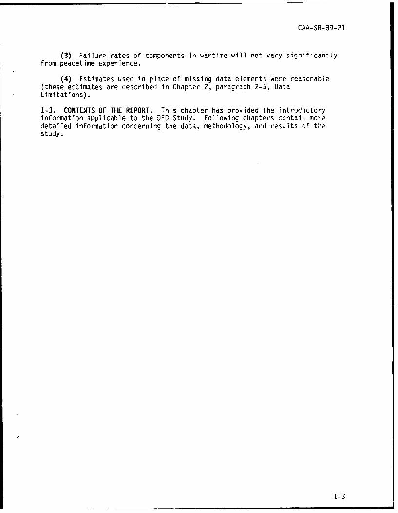
Table 4-7. Results of Excursion 2 - Unconstrained
Change inTheater strength due SRCs SRC descriptions
to DFD
NATO -563 43237J50010 CS CO LEMCO43238J50010 CS CO HVY EQP MAINT43238J50210 CS TM FLD ARTY REPAIR43509LC0010 MT TM TRACK VEH REPAIR43509LCOOHI MT TM TRACK VEH REPAIR43509LG0010 MT TM WHEEL VEH43509LGOOHI MT TM WHEEL VEH
SWA 0
NEA -200 43209L00010 MT CO
Table 4-8. Results of Excursion 2 - Constrained
Change inTheater strength due SRCs SRC descriptions
to DFD
NATO 0
SWA 0
NEA 0
(3) As can be seen from Tables 4-6 through 4-3, the decrements inmaintenance manhours and the resultant force structure savings did not varyto a large degree between the DFD base case and the two excursions. In otherwords, the sensitivity analysis showed that variations in the economic cri-teria did not produce large differences in the results. Figure 4-1 shows, bytheater, the difference in force structure savings for the base case and thetwo excursions. It demonstrates that the model results were not sensitive tochanges in the cost criteria.
4-8

CAA-SR-89-21
Changeinstrength due
to DFD
600 NATO-
SWA500 NEA
400
300
200
100
0
-100
$250K $500K $1MEconomic criteria
Figure 4-1. Results by Theater (unconstrained),Base Case and Excursions
4-6. MAGNITUDE OF FORCE STRUCTURE SAVINGS. Table 4-9 provides insight intothe magnitude of the force structure savings achieved in this study. Thelargest drop in strength for each theater, which occurred in Excursion 2, isshown along with the beginning strength or total population in the theater atthe outset of the FASTALS run. The percentage change between the beginnirgstrength and the savings in strength due to DFD shows that the savings arenot significant. Table 4-10 presents the same information, but, in place ofthe beginning strength, the beginning maintenance strength (a subset of thetotal population) is provided by theater. The drop in strength relative tothe beginning maintenance population is also very small.
4-9

CAA-SR-89-21
Table 4-9. Magnitude of Force Structure Savings(relative to beginning strength)
Beginning total Largest drop in PercentageTheater strength strength change
NATO 1,106,000 563 -.05%
SWA 408,000 0 0%
NEA 139,000 200 -.14%
Table 4-10. Magnitude of Force Structure Savings(relative to beginning maintenance strength)
Beginning Largest drop in PercentageTheater maintenance
strength strength change
NATO 40,867 563 -1.4%
SWA 18,485 0 0%
NEA 6,557 200 -3.0%
4-7. ANSWERS TO EEA
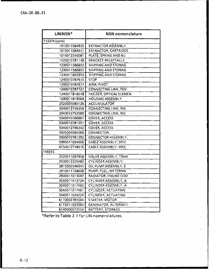
a. EEA 1. The first EEA was to identify existing reparable componentsfor possible reclassification as throwaway components. Table B-I in AppendixB shows, by LIN and NSN, components currently classified as reparable whichwere identified in the OFO Study as throwaway candidates. (Note that NSNnomenclature fields were provided with a maximum width of 19 characters.Many of the names are cut o-f at that point.)
b. EEA 2. The second EEA was to identify military spaces by MOS and SRLwhich could be realigned or converted to other MOSs. The military spacesidentified in the DFD Study as candidates for possible conversion are thoselisted in Table 4-1 by LIN, ECH, and MOS. The SRCs associated with theseMOSs are those shown in Table 4-2 (for the base case).
c. EEA 3. EEA 3 was to determine the impact on the Atmy force structureof the DFD concept within the limits of the DFD Study. In terms of resultsproduced in this study, force structure savings appear to be negligible.However, this determination was made on the basis of available tools anddata. Discussion about what conclusions can be drawn from the results ofthis study and recommendations for further study are presented in the nextparagraph.
4-10

CAA-SR-89-21
4-8. CONCLUSIONS AND RECOMMENDATIONS. The purpose of the DFD Study was todetermine the impact of DFD on the Army's CSS'force structure. At facevalue, the results of the study indicate that force structure savingsresulting from the use of the DFD concept are nonexistent to negligible.These results, however, were heavily dependent on the methodology used andthe available tools. The study results are inconclusive in that they do notprovide a strong basis for a decision as to the usefulness of the DFD con-cept. It is not felt that a decision regarding the implementation of the DFDconcept should be made based solely on the study results. The reasons forthis assessment are the following.
a. One of the fundamental concepts on which the OFD Study was based wasthe economic methodology. The PLRC was used as the basis for the decision asto whether a component would be considered for reclassification from areparable component to a discardable item. Labor savings (the number ofmaintenance manhours that would be saved by reclassifying these components)were then computed for the items meeting the economic criteria. It isrecommended that further study be done which would focus on the componentswhich require the greatest number of manhours to repair, rather than usingcost criteria as the primary consideration.
b. The only tool available at CAA to measure a change in CSS force struc-ture is the FASTALS Model. FASTALS provided a means to assess savings interms of entire units, based on reductions in maintenance manhours appliedthrough the use of the MARC file. The changes made to the MARC file for theDFO Study were considered small in relation to changes made in other appli-cations. Reductions in manhours amounted to about 8 percent (for the 46 enditems making up 48 percent of the total maintenance workload). FASTALS isnot sensitive to small changes in MARC data. That is, it is not unusual fora strength change of zero (i.e., no units "kick out") to result from smallchanges in MARC data. Also, FASTALS does not provide insights into forcestructure savings at any level less than unit level. This means that savingsby SRC are available, but savings by MOS within SRC are not. Other inherentproperties of the FASTALS Model that affect results are such things asrounding rules, allocation rules, and number of time periods considered.These properties had some effect on the results of the DFD Study as well.
c. It is recommended that further study of the DFO concept be conductedby TRADOC, possibly to include component replacement, in lieu of repair,resulting from combat damage. As long as the Army's maintenance structureremains as it is, it is felt that any assessment of force structure savingswill have results similar to those of this study. The maintenance structuremust be redesigned to allow for the DFD concept before any significantsavings in force structure can be realized. Changes in unit design andallocation rules are necessary for the DFO concept to prove productive in thearea of force structure savings.
4-11
CAA-SR-89-21
APPENDIX A
STUDY CONTRIBUTORS
1. STUDY TEAM
a. Study Director
Ms. Julianne Allison, Office of the Special Assistant for ModelValidation
b. Team Member
Mr. Giles D. Mills III
c. Other Contributors
Mr. Kenneth E. Allison
2. PRODUCT REVIEW BOARD
Mr. R. Glenn Stockton, Chairman
CPT Arnethia B. Murdock
Ms. Rebecca Merle
3. EXTERNAL CONTRIBUTORS
Mr. Walter Hodgins, US Army Materiel Command
Dr. Donald Orr, Inventory Research Office, US Army Materiel SystemsAnalysis Activity
A-I

CAA-SR-89-21
APPENDIX B
CANDIDATES FOR RECLASSIFICATIONAS DISCARDABLE ITEMS
LIN/NSN* NSN nomenclature
C 10908
2510010934311 WIRING HARNESS, BRAN
2520008949535 TRANSFER ASSEMBLY A
2520009649203 FINAL DRIVE WITH CO
2530001320842 ARM ASSEMBLY, PIVOT
2530005370372 ARM ASSEMBLY, PIVOT
2530005370434 ARM ASSEMBLY, SUSPEN
2530011885089 BRAKE, HYDRAULIC
2540007821169 FAN, PERSONNEL HEATE
2540011623834 HEATER, VEHICULAR, CO
2540011695159 HEATER, VEHICULAR, CO
2540011799024 SHROUD, DOOR
2590004463639 WIRING HARNESS, BRAN
2590008712834 PUMP, BILGE
2590011583087 ACTUATOR, HYDRAULIC
2815010403120 ENGINE W CONTAINEr%
2815011757342 ENGINE, DIESEL
2910000893947 TANK, FUEL, ENGINE
2910007821376 PUMP, FUEL AND HANGE
2910009377435 PUMP, FUEL, ELECTRICA
2910009379539 TANK, FUEL, ENGINE
2920004751446 GENERATOR, ENGINE AC
2930009216475 DRIVE ASSEMBLY, FAN
2930010383666 RADIATOR, ENGINE COO
4140000162615 FAN, CENTRIFUGAL
4140007563612 FAN, VANEAXIAL
4320008712834 PUMP, BILGE
6105010921484 MOTOR, DIRECT CURRENT
6105012005091 MOTOR, DIRECT CURRENT
6130009999825 RECTIFIER ASSEMBLY
6140012101964 BATTERY, STORAGE
*Refer to Table 2-1 for LIN nomenclatures.
B-1

CAA-SR-89-21
LIN/NSN* NSN nomenclature
C12155
2540010870998 SUPPORT RING, COMMAN
3040010529047 BELL CRANK
6135010764282 BATTERY BOX
C76335
1005010990163 TRAVEL LOCK ASSY
1005010991746 CABLE ASSEMBLY, 2W17
1005010991747 CABLE ASSEMBLY
1005010991748 CABLE ASSEMBLY
1005011091557 CAMSHAFT ASSEMBLY
1005011103420 BOX, FEEDER, AMMO
1005011114048 CIRCUIT CARD ASSY
1005011126331 CABLE ASSY
1005011128254 LEVER, REMOTE CONTRO
1005011128556 CAMSHAFT ASSEMBLY, T
1005011128571 CABLE ASSY SW, ELEC
1005011140072 CAMSHAFT ASSEMBLY E
1005011179821 CONTROL BOX, WEAPON
1005011408144 WIRING HARNESS, BRAN
1005011988684 GRIP ASSEMBLY, CONTR
1005011988685 GRIP ASSEMBLY, CONTR
1005012042418 GRIP ASSEMBLY, CONTR
1430010860932 CONTROL BOX, TOW
2540011077554 SEAT, GUNNERS
2540011114963 SEAT, COMMANDERS
2590011024655 WIRING HARNESS, BRAN
5340011400211 CLEVIS, ROD END
5905011295991 RESISTOR, STEP BY ST
5930011122489 SWITCH, SENSITIVE
5930011128500 SWITCH, SENSITIVE
6230012372953 LIGHT, EXTENSION6330011122795 ANNUNCIATOR
*Refer to Table 2-1 for LIN nomenclatures.
B-2

CAA-SR-89-21
LIN/NSN* NSN nomenclature
D11049
2590007409565 BRANKE BAND AND LINI
2920010319027 STARTER, ENGINE, ELEC
2940001035791 BODY, AIR CLEANER
D11533
2990000741948 HEATER ASSEMBLY, AIR
E56896
1005006108986 LOCK ASSEMBLY, PINTL
2520010764262 UNIVERSALJOINT
2530010373310 ARM, TRACK IDLER
2590004462487 CYLINDER ASSEMBLY, A
J35813
2910010472012 PUMP, FUEL, INJECTION
J35825
2805012500039 GOVERNOR ASSEMBLY
2920012017370 MODULATOR ASSEMBLY,
2990010852554 DUCT AND SHUTTER AS
J42100
2805004547511 CRANKCASE ASSEMBLY
5950007878615 TRANSFORMER, CURRENT
6110007647621 REGULATOR, VOLTAGE
6115002512087 CONTROL BOX ASEMBL
6115009407859 ROTOR ASSEMBLY, GENE
J43918
6150009097339 WIRING HARNESS, BOXR
J44055
2805012500039 GOVERNOR ASSEMBLY
2920012017370 MODULATOR ASSEMBLY,
6115007645464 FRAME
6150009097339 WIRING HARNESS, BOXR
J45699
6110007647621 REGULATOR, VOLTAGE
6115009490604 HOUSING ASSEMBLY, GE
6115009995675 GENERATOR ASSEMBLY
*Refer to Table 2-1 for LIN nomenclatures.
B-3

CAA-SR-89-21
LIN/NSN* NSN nomenclature
J46110
6110007647621 REGULATOR, VOLTAGE
6115009490604 HOUSING ASSEMBLY, GE
6115009995675 GENERATOR ASSEMBLY
J47617
2805000178330 CYLINDER, ENGINE, GAS
6110007647621 REGULATOR, VOLTAGE
6110009139275 DISTRIBUTION BOX
6115011715858 HOUSING ASSEMBLY
J81750
1005010990163 TRAVEL LOCK ASSY
1005010991746 CABLE ASSEMBLY, 2W17
1005010991747 CABLE ASSEMBLY
1005010991748 CABLE ASSEMBLY
1005011091557 CAMSHAFT ASSEMBLY
1005011103420 BOX, FEEDER, AMMO
1005011114048 CIRCUIT CARD ASSY
1005011126331 CABLE ASSY
1005011128254 LEVER, REMOTE CONTRO
1005011128556 CAMSHAFT ASSEMBLY, T
1005011128571 CABLE ASSY SW, ELEC
1005011140072 CAMSHAFT ASSEMBLY, E
1005011179821 CONTROL BOX, WEAPON
1005011408144 WIRING HARNESS, BRAN
1005011988684 GRIP ASSEMBLY, CONTR
1005011988685 GRIP ASSEMBLY, CONTR
1005012042418 GRIPASSEMBLY, CONTR
2540011077554 SEAT, GUNNERS
5340011400211 CLEVIS, ROD END
5905011295991 RESISTOR, STEP BY ST
5930011122489 SWITCH, SENSITIVE
5930011128500 SWITCH, SENSITIVE
6230012372953 LIGHT, EXTENSION
6350011122795 ANNUNCIATOR
*Refer to Table 2-1 for LIN nomenclatures.
B-4

CAA-SR-89-21
LIN/NSN* NSN nomenclature
K29694
1560001336224 FITTING ASSEMBLY, MO
1560008160790 DOOR, ACCESS
1560009731754 TANK, LUBRICATING 01
1615000701130 DAMPER ASSEMBLY, TRA
1630002470249 KID TUBE ASSY, LH
1650010596006 HYDRAULIC UNIT, MODU
1680001323364 PANEL, INDICATING, LI
2915000035904 FILTER, FLUID
2915011245222 PUMP, SUBMERGED, AIRC
K31042
1560011101443 DOOR ASSEMBLY, CREW,
6220001795106 LIGHT, NAVIGATIONAL,
K32293
1560011101443 SLIDE ASSEMBLY, WIND
K56981
1025005570575 PIN, HINGE
1025010325114 TORQUE LOCK, DRIVE A
1025010325116 DIFFERENTIAL GEAR U
1025010414385 HEADLINK ASSEMBLY
1025012279770 CYLINDER ASSEMBLY, A
1030007910143 COUNTERBALANCE ASSE
2520010377279 FINAL DRIVE, TRAVERS
3010005362773 GEAR ASSEMBLY, SPEED
3040009811251 HEAD, LINEAR ACTUATI
3040012275546 CAM, CONTROL
5340010197144 LATCH SET, RIM
5340010311757 LOCK SET, RIM
K576670
1015006093977 VALVE, SAFETY RELIEF
1025000195267 CRANK, OPERATING ASS
1025001150627 CYLINDER ASSEMBLY, L
1025001272921 ACCUMULATOR, HYDRAU L1025001778345 VALVE ASSEMBLY
1025001797142 COVER ASSEMBLY, POWE
*Refer to Table 2-1 for LIN nomenclatures.
3-5

CAA-SR-89-21
LIN/NSN* NSN nomenclature
K576670 (cont)
1025001837678 MANIFOLD ASSEMBLY
1025003320083 VALVE, SHUTTEL ASSY
1025004396541 LEVER, CAM ASSEMBLY
1025006893405 EYE ASSEMBLY, CYLIND
1025006893406 EYE ASSEMBLY, PISTON
1025008Uz2465 HOUSING ASSEMBLY
1025008166592 BEARING UNIT, HAND D
1025008688060 GEARSHAFT ASSEMBLY,
1025009197277 RECUPERATOR CYLINDE
1025009197905 COVER, RECUPERATOR C
1025009298328 SHIM
1025009997931 HOUSING, FIRING MECH
1025010189182 SUPPORT ASSY, REAR
1025010552790 BODY ASSEMBLY
1025010561250 CYLINDER, BUFFER
1025010592488 VALVE ASSEMBLY RAMM
1025010643374 ROLLER ASSEMBLY
1025010703223 HANDLE ASSEMBLY
1025010710623 RETAINER ASSEMBLY
1025010927901 POWER PACK ASSEMBLY
1025010950899 MOUNTASSEMBLY
1025012532033 FILTER, FLUID ASSEMB
1240003285623 M145 MT TEL
1240004888665 LEVEL ASSEMBLY
1240008640343 CELL ASSEMBLY, OPTIC
1240008640363 TEL P M 117A2
1240008715475 M15 QUAD FC
124001,1495951 QUADRANT SUPPORT AS
1240011495952 COUNTER BOX ASSEMBL
1240011789752 LAMP ASSEMBLY, TELES
1290004707504 QUAD M1A1
1290008919999 QUADRANT, FIRE CONTR
1290008962236 QUADRANT, FIRE CONTRO
*Refer to Table 2-1 for LIN nomenclatures.
B-6

CAA-SR-89-21
LIN/NSN* NSN nomenclature
K576670 (cont)
1290011484821 LIGHT, AIMING POST
2520004751278 BODY, VALVE, BYPASS
2520005080126 ACCUMULATOR
2520008883715 HANDLE, GUNNERS CON
2520009722625 VALVE, RELIEF, TURRET
2520009722627 MOTOR, HYDRAULIC
2590001797159 HARNESS, HANDLE GUNN
2590002694853 WIRING HARNESS, BRANC
259000P235586 LEAD ASSEMBLY, ELECT
3040009318206 CONNECTING LINK, RIG
4320001743439 PUMP, AXIAL PISTONS
4320009307862 PUMP ASSEMBLY
4810004706533 VALVE, LINEAR, DIRECT
4820004751272 BODY, SELECTOR VALVE
5315000852261 PIN, SHOULDER, HEADLE
5340001747758 PLUNGER ASSEMBLY, CA
5340010691591 DOOR, ACCESS
5355008986791 KNOB ASSEMBLY
5925008405393 CIRCUIT BREAKER
5935007388305 CONNECTOR, RECEPTICL
5935007751500 RECEPTICLE WIRING H
5975000531074 INTERCONNECTING BOX
6105010953087 MOTOR, DIRECT CURREN
6150000840240 LEAD ELECTRICAL, BRA
6150009673351 LEAD ELECTRICAL, BRA
6150010718507 WIRING HARNESS
9340004939060 WINDOW, OBSERVATION
K576671
1015006093977 VALVE, SAFETY RELIEF
1025001150627 CYLINDER ASSEMBLY,L
1025001837678 MANIFOLD ASSEMBLY
1025003320083 VALVE, SHUTTLE ASSY
1025004396541 LEVER, CAM ASSEMBLY
1025006893405 EYE ASSEMBLY, CYLIND
1025006893406 EYE ASSEMBLY, PISTON
*Refer to Table 2-1 for LIN nomenclatures.
B-7

CAA-SR-89-21
LIN/NSN* NSN nomenclature
K576671 (cont)
1025008022465 HOUSING ASSEMBLY
1025008166592 BEARING UNIT, HAND D
1025008688060 GEARSHAFT ASSEMBLY,
1025009197905 COVER, RECUPERATOR C
1025010552790 BODY ASSEMBLY
1025010592488 VALVE ASSEMBLY RAMM
1025010643374 ROLLER ASSEMBLY, CUR
1025010710623 RETAINER ASSEMBLY
1025010927901 POWER PACK ASSEMBLY
1025010950899 MOUNTASSEMBLY
1025012532033 FILTER, FLUID ASSEMB
1240001150637 WIRING HARNESS, BRAN
1240004888665 LEVEL ASSEMBLY
1240008640343 CELL ASSEMBLY, OPTIC
1240008640363 TEL P M 117A2
1240008642933 PERISCOPE
1240008688381 PRISM, DOVE, ASSEMBLY
1240008706277 GEAR-PRISM OPTICAL
1240011495951 QUADRANT SUPPORT AS
1240011495952 COUNTER BOX ASSEMBL
1240011506094 CELL ASSEMBLY, OPTIC
1240011518841 RETICLE ASSEMBLY, OP
1240011656247 SEGMENT ASSEMBLY, GE
1240011789752 LAMP ASSEMBLY, TELES
1290008919999 QUADRANT, FIRE CONTR
1290008962236 QUADRANT, FIRE CONTR
2520004751278 BODY, VALVE, BYPASS
2520005080126 ACCUMULATOR
2520008883715 HANDLE, GUNNERS CON
2520009722625 VALVE, RELIEF, TURRET
2590001797159 HARNESS, HANDLE GUNN
3040009318206 CONNECTING LINK, RIG
4810004706533 VALVE, LINEAR, DIRECT
*Refer to Table 2-1 for LIN nomenclatures.
B-8

CAA-SR-89-21
LIN/NSN* NSN nomenclature
K576671 (cont)
4820004751272 BODY, SELECTOR VALVE5315000852261 PIN, SHOULDER, HEADLE5355008986791 KNOB ASSEMBLY9340004939060 WIN DOW, OBSERVATION
P450032835004204332 DRIVE ASSY, DUAL PAD
2835008638496 GEAR BOX, ACCESSORY D2910009081429 FUEL CONTROL, ASSY2920009330578 WIRE HARNESS2930003374818 COOLER/REG ASSY, OIL4130008638549 WIRE HARNESS4130009330570 FAN, RECIRCULATE ASSY6115002479944 WIRE HARNESS6115002479947 WIRE HARNESS6115002489988 WIRE HARNESS6115004557712 WIRE HARNESS6115008337785 WIRE HARNESS6115008437627 WIRE HARNESS6115008437650 WIRE HARNESS, HEAT
6115008438605 WIRE HARNESS6115008438621 WIRE HARNESS6115008592382 WIRE HARNESS6115008716658 WIRE HARNESS6150002480063 WIRE HARNESS
R50544
2510004381595 DOOR, HATCH, VEHICLE
2510004434864 DOOR, HATCH, VEHICLE2510004434865 DOOR, HATCH, VEHICLE2510004434879 DOOR, METAL SWINGING2510004535448 TREAD, METALLIC, NONS2510004535449 TREAD, METALLIC, NONS2510004535450 TREAD, METALLIC, NONS2510004535451 TREAD, METALLIC, NONS
*Refer to Table 2-1 for LIN nomenclatures.
B-9

CAA-SR-89-21
LIN/NSN* NSN nomenclature
T05028
2530011479329 CALIPER, DISC BRAKE
2530011529305 DRUM ASM-RR BRK
2530011566190 CALIPER, DISC BRAKE
T07543
2510011739316 TAILGATE, VEHICLE BO
2510011739347 HOOD, ENGINE COMPART
2520011491866 BODY ASSEMBLY, PUMP,
2520011885115 AXLE ASSEMBLY, AUTOM
2530011687876 PUMP ASSEMBLY, POWER
2530011856712 ROTOR
2530012042583 HOUSING ASSEMBLY, CA
2530012076256 HOUSING ASSEMBLY, CA
2540011975524 TOP ASSEMBLY, TRUCK
2540011975528 CURTAIN, VEHICULAR
2815011658216 CYLINDER HEAD, DIESE
2910011714636 PUMP, FUEL, METERING
2930011687870 DRIVE, FAN
2930011687911 COOLER, LUBRICATING
2930011992398 RADIATOR, ENGINE COO
T13168
1015011815924 LOCK, BEARING
1015011815925 LOCK, BEARING
1015012032735 ROTOR, GUN MOUNT
1220010781138 BRACKET-RECEPTABLE
1230011586805 SHIPPING AND STORAG
1230011602953 SHIPPING AND STORAG
1240010761815 HOUSING
1240010787615 STOP
1240010787617 ARM, PIVOT
1240010787727 CONNECTING LINK, FOV
1240011816018 HOLDER, OPTICAL ELEM
1240011819069 HOUSING ASSEMBLY
1240011924058 OBJECTIVE AND RELAY
1240012546344 CELL, OPTICAL ELEMEN
*Refer to Table 2-1 for UN nomenclatures.
B-10

CAA-SR-89-21
LIN/NSN* NSN nomenclature
T13168 (cont)
2510010749011 DOOR, HATCH, VEHICLE
2520005080126 ACCUMULATOR
3040012746354 CONNECTING LINK, RIG
3040012752589 CONNECTING LINK, RIG
5340010761874 COVER, ACCESS
5340010766867 COVER, ACCESS
5340010781301 COVER, ACCESS
5340012746342 COVER, ACCESS
5935004084368 CONNECTOR,
5935010781292 CONNECTOR ASSEMBLY,
T13169
1015001139602 HANGER, TURRET PLATE1015005663827 SHAFT, OVERRIDE ELEV1015005663840 SHAFT, OVERRIDING, TR
1015006093977 VALVE, SAFETY RELIEF
1015006466858 YOKE ASSEMBLY PUMP1015007792532 SHIELDASSEMBLY1015010144716 BOX, ASSEMBLY, AMMU NI
1015010217266 HOUSING ASSEMBLY
1015010327144 HOUSING ASSEMBLY1240004579370 HANDLE ASSEMBLY1240011819069 HOUSING ASSEMBLY
2520004517713 BOX ASSEMBLY
5305008007261 SET SCREW
6130012692279 POWER SUPPLY SUBASS
T13374
1015010749018 WIRING HARNESS, BRAN
1015010766722 ROTOR, GUN MOUNT
1015010766783 WIRING HARNESS
1015010766784 WIRING HARNESS
1015010766785 WIRING HARNESS
1015010766786 WIRING HARNESS
1015010766787 WIRING HARNESS
1015010766790 WIRING HARNESS
*Refer to Table 2-1 for LIN nomenclatures.
B-ll
CAA-SR-89-21
LIN/NSN* NSN nomenclature
T13374 (cont)
1015011084930 EXTRACTOR ASSEMBLY1015011084931 EXTRACTOR, CARTRIDGE1015012240081 PLATE, SPRING AND BU1220010781138 BRACKET-RECEPTACLE1230011586802 SHIPPING AND STORAG1230011586805 SHIPPING AND STORAG1230011602953 SHIPPING AND STORAG
1240010787615 STOP
1240010787617 ARM, PIVOT1240010787727 CONNECTING LINK, FOV1240011816018 HOLDER, OPTICAL ELEMEN1240011819069 HOUSING ASSEMBLY2520005080126 ACCUMULATOR3040012746354 CONNECTING LINK, RIG3040012752589 CONNECTING LINK, RIG
5340010766867 COVER, ACCESS5340010781301 COVER, ACCESS
5340012746342 COVER, ACCESS5935004084368 CONNECTOR,
5935010781292 CONNECTOR ASSEMBLY,5995011054006 CABLE ASSEMBLY, SPEC
6150012718016 CABLE ASSEMBLY, SPECT49255
2520011097958 VALVE ASSEMBLY, TRAN2530012225482 CYLINDER ASSEMBLY,2815000546945 OIL PUMP ASSEMBLY, E2910011148608 PUMP, FUEL, METERING2930011013047 RADIATOR, ENGINE COO
3040011013726 CYLINDER ASSEMBLY, A3040011017460 CYLINDER ASSEMBLY, A3040011017461 CYLINDER, ACTUATING3040011024224 CYLINDER, ACTUATING6110002781044 STARTER, MOTOR6115011023063 GENERATOR, ALTERNATI
6140000572554 BATTERY, STORAGE
*Refer to Table 2-1 for LIN nomenclatures.
8-12
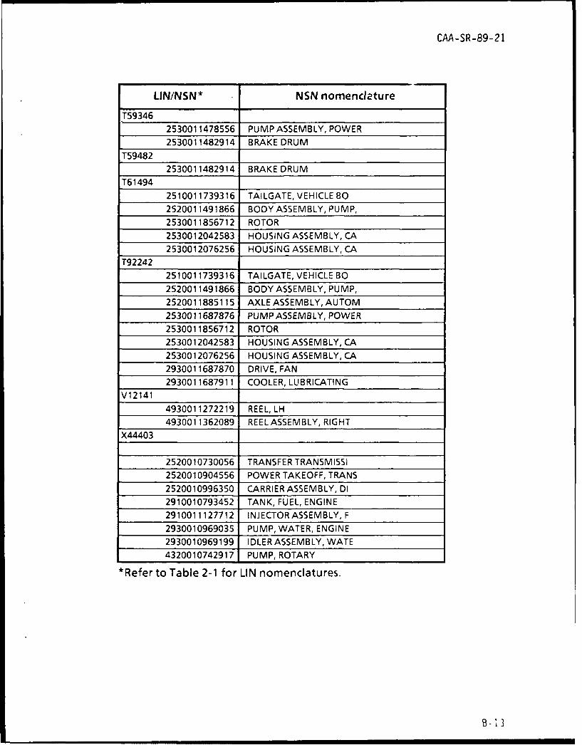
CAA-SR-89-21
LIN/NSN* NSN nomenclature
T593462530011478556 PUMP ASSEMBLY, POWER2530011482914 BRAKE DRUM
T59482
2530011482914 BRAKE DRUM
T61494
2510011739316 TAILGATE, VEHICLE BO2520011491866 BODY ASSEMBLY, PUMP,2530011856712 ROTOR2530012042583 HOUSING ASSEMBLY, CA2530012076256 HOUSING ASSEMBLY, CA
T92242
2510011739316 TAILGATE, VEHICLE BO2520011491866 BODY ASSEMBLY, PUMP,2520011885115 AXLE ASSEMBLY, AUTOM2530011687876 PUMP ASSEMBLY, POWER
2530011856712 ROTOR2530012042583 HOUSING ASSEMBLY, CA2530012076256 HOUSING ASSEMBLY, CA2930011687870 DRIVE, FAN2930011687911 COOLER, LUBRICATING
V12141
4930011272219 REEL, LH
4930011362089 REEL ASSEMBLY, RIGHT"X44403
2520010730056 TRANSFER TRANSMISSI2520010904556 POWER TAKEOFF, TRANS2520010996350 CARRIER ASSEMBLY, DI2910010793452 TANK, FUEL, ENGINE2910011127712 INJECTOR ASSEMBLY, F2930010969035 PUMP, WATER, ENGINE2930010969199 IDLER ASSEMBLY, WATE4320010742917 PUMP, ROTARY
*Refer to Table 2-1 for LIN nomenclatures.
B-13

CAA-SR-89-21
APPENDIX C
BIBLIOGRAPHY
DEPARTMENT OF THE AR;.Y
Briefing slides, Army Materiel Systems Analysis Activity, Inventory ResearchOffice, Aug 87, subject: The APRICOT Analysis: Approximate Proceduresto Reevaluate Reparable Items' Costs for the Option Throwaway
Memorandum, Armament Munitions & Chemical Command, AMSMC-MAF-AP,2 Sep 88, subject: Design for Discard Data Call
Memorandum, Armament Munitions & Chemical Command, AMSMC-MAF-AP,18 Aug 88, subject: SAB
Memorandum, Armament Munitions & Chemical Command, AMSMC-MAF-AP,11 Aug 88, subject: SAB
Memorandum, Armament Munitions & Chemical Command, AMSMC-MA, 7 Aug 88,subject: SAB
Memorandum, Army Materiel Command, AMCRE-C, 10 Feb 88, subject: Analysis ofDesign for Discard on the Army's Future Combat Service Support Structure
Memorandum, Army Materiel Command, AMCRE-C, 23 Jun 88, subject: Design forDiscard Data Call
Memorandum, Army Materiel Systems Analysis Activity, AMXSY-LIRO, 16 Sep 88,subject: Discard of M939 and M109 Reparables ("Design to Discard"APRICOT Analysis)
Memorandum, Aviation Systems Command, AMSAV-MMD, 1 Nov 88, subject:Design for Discard
Memorindum, Aviation Systems Command, AMSAV-MMP, 28 Sep 88, subject: SAB
Memorandum, Aviation Systems Command, AMSAV-MCA, 30 Aug 88, subject:Design for Discard Data Call
Memorandum, Communications-Electronics Command, AMSEL-LC-ME-MPM,
30 Aug 88, subject: SAB
Memorandum, Missile Command, AMSMI-LC-ME-TD, 26 Aug 88, subject: SAB
Memorandum, Tank-Automotive Command, AMSTA-MMBA, 1 Aug 88, subject: SAB
Publication, US Army Concepts Analysis Agency (CSCA-FO), Nov 83 (rev. Jun88), User's Manual for Force Analysis Simulation of TheaterAdministrative and Logistic Support (FASTALS) Model (CAA-D-83-4)
Publication, US Army Logistics Center (ATCL-FO), Sep 86, Army MARCMaintenance Data Base (AMMDB)
C-I

CAA-SR-89-21
MISCELLANEOUS
Howell, C. and Siorek, R., "Towards an Affordable Armed Force," NationalDefense, Mar 1984, pp 50-55
McDavid, Dan, "Design-For-Discard In Systems Engineering," Army Research,Development and Acquisition Bulletin, Nov-Dec 88, pp 17-19
Murry, COL William V., "Design-for-Discard," Army Research, Development andAcquisition Bulletin, Jul-Aug 87, pp 1-4
C-2
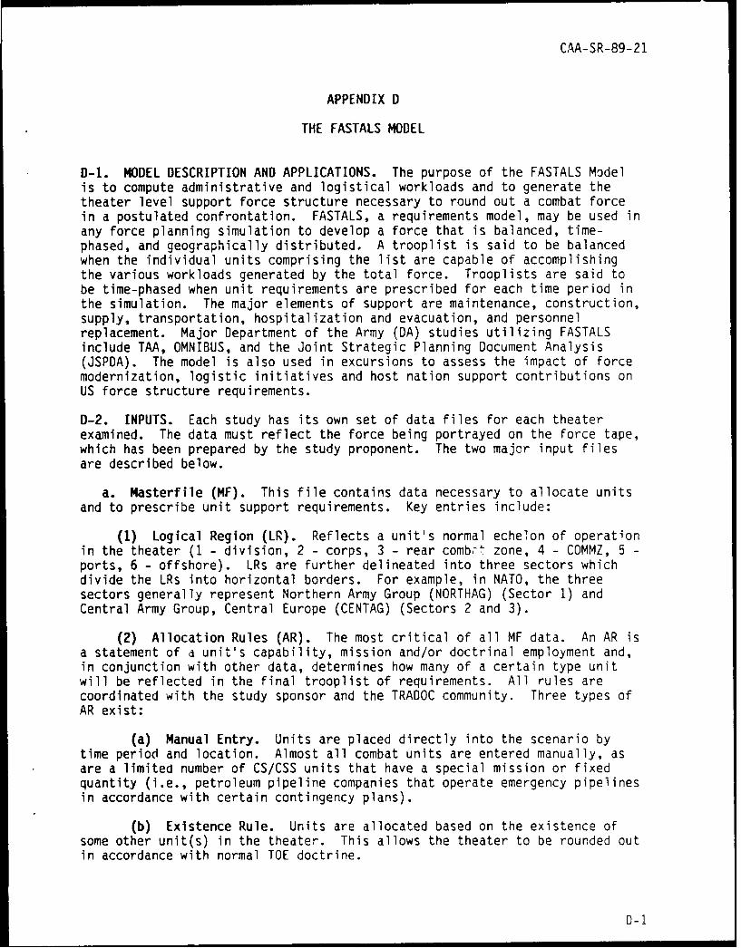
CAA-SR-89-21
APPENDIX D
THE FASTALS MODEL
D-1. MODEL DESCRIPTION AND APPLICATIONS. The purpose of the FASTALS Modelis to compute administrative and logistical workloads and to generate thetheater level support force structure necessary to round out a combat forcein a postulated confrontation. FASTALS, a requirements model, may be used inany force planning simulation to develop a force that is balanced, time-phased, and geographically distributed. A trooplist is said to be balancedwhen the individual units comprising the list are capable of accomplishingthe various workloads generated by the total force. Trooplists are said tobe time-phased when unit requirements are prescribed for each time period inthe simulation. The major elements of support are maintenance, construction,supply, transportation, hospitalization and evacuation, and personnelreplacement. Major Department of the Army (DA) studies utilizing FASTALSinclude TAA, OMNIBUS, and the Joint Strategic Planning Document Analysis(JSPDA). The model is also used in excursions to assess the impact of forcemodernization, logistic initiatives and host nation support contributions onUS force structure requirements.
D-2. INPUTS. Each study has its own set of data files for each theaterexamined. The data must reflect the force being portrayed on the force tape,which has been prepared by the study proponent. The two major input filesare described below.
a. Masterfile (MF). This file contains data necessary to allocate unitsand to prescribe unit support requirements. Key entries include:
(1) Logical Region (LR). Reflects a unit's normal echelon of operationin the theater (1 - division, 2 - corps, 3 - rear combr zone, 4 - COMMZ, 5 -ports, 6 - offshore). LRs are further delineated into three sectors whichdivide the LRs into horizontal borders. For example, in NATO, the threesectors generally represent Northern Army Group (NORTHAG) (Sector 1) andCentral Army Group, Central Europe (CENTAG) (Sectors 2 and 3).
(2) Allocation Rules (AR). The most critical of all MF data. An AR isa statement of a unit's capability, mission and/or doctrinal employment and,in conjunction with other data, determines how many of a certain type unitwill be reflected in the final trooplist of requirements. All rules arecoordinated with the study sponsor and the TRADOC community. Three types ofAR exist:
(a) Manual Entry. Units are placed directly into the scenario bytime period and location. Almost all combat units are entered manually, asare a limited number of CS/CSS units that have a special mission or fixedquantity (i.e., petroleum pipeline companies that operate emergency pipelinesin accordance with certain contingency plans).
(b) Existence Rule. Units are allocated based on the existence ofsome other unit(s) in the theater. This allows the theater to be rounded outin accordance with normal TOE doctrine.
D-1

CAA-SR-89-21
(c) Workload Rule. Units are allocated based on the capability toaccomplish generated workloads.
Other data found in the MF include standard requirements codes, unitdescriptions, strengths and weights of the units.
b. Scenario. This data set represents the major variable inputs which,when combined with the MF, generates the statement of support forcerequirements.
(1) Combat Simulation Data. The combat data required to run FASTALSinclude unit location and employment time, level of combat intensity,ammunition consumption, damaged and repairable tanks/armored personnelcarriers (APCs), casualties, and changes in forward edge of the battle area(FEBA).
(2) Other Data. Other data provided include a layout of the theater'sgeographical structure; number of forward deployed and prepositioned materielconfigured to unit sets (POMCUS) units; prepositioned war reserve materielstock (PWRMS), stockage policy and supply data; engineer construction policy;and transportation data representing links, paths, and capacities for eachmode (highway, railroad, waterway, pipeline).
D-3. EXECUTION. First, the combat units employed by the combat model areaugmented by direct input units and by units that are implied by the organi-zational structure of the theater being analyzed (e.g., number of corps).Next, units that are required on the basis of the existence of other units inthe theater are added to the list. The model then computes workloads gener-ated by these units in terms of personnel replacements, hospital admissions,supplies, maintenance, construction, and transportation. These workloads arethen used as a basis for adding units such as hospitals and medium truckcompanies. This new set of units generates another increment, and so thecycling process begins. Additional units increase the workloads which, inturn, generate a requirement for more units. This cyclic process, steps 5through 13 in Figure 0-1, continues until the model computes the same set ofunits (trooplist) that was computed on the previous cycle (requirementsconverge).
0-4. OUTPUTS. The principle output produced is the time-phased troopdeployment list of theater requirements. Other reports provide consumptionand stockage requirements for each category of supply. Additional reportsThclude 48 workload summaries that relate to personnel replacements, medical,materiel, maintenance, construction, transportation, and casualties.
0_2

CAA-SR -89-21
COMBAT UNITS8
DIRECT INPUTCOPT
UNITS PRONL1
3 UNITS BASED ONII
THEATER OHRNT OPTORGANIZATION13CNTUIO
COMBAT WKLDS KD& INTENSITIES
Figure D-1. FASTALS Logic Flow
D-3

CAA-SR-89-21
APPENDIX E
DISTRIBUTION
Addressee No ofcopies
Deputy Chief of Staff for LogisticsHeadquarters, Department of the ArmyATTN: DALO-ZXA-ARoom 30572, The PentagonWashington, DC 20310-0580
CommanderUS Army Logistics CenterATTN: ATCL-CFS/Classified CustodianFort Lee, VA 23801
Defense Technical Information Center 2ATTN: DTIC-FPSCameron StationAlexandria, VA 22314-6145
US Army Service Center for theArmed Forces
The Pentagon Library (Army StudiesSection)
ATTN: ANRAL-RS/Security OfficerRoom 1A518, The PentagonWashington, DC 20310-6000
CommanderUS Army Ordnance Center and SchoolATTN: ATSL-CMTAberdeen Proving Ground, MD 21005-5201
CommandantUS Army Ordnance, Missile and Munitions
Center and SchoolATTN: ATSK-CMTRedstone Arsenal, AL 35897-6000
E-1

CAA-SR-89-21
No ofIAddressee copies
Commandant 1US Army Quartermaster SchoolATTN: ATSM-OS (Mr. Armstrong)Fort Lee, VA 23801-6043
Headquarters 3US Army Materiel CommandATTN: AMCRE-C5001 Eisenhower AvenueAlexandria, VA 22333-0001
Commander 1US Army Tank-Automotive CommandATTN: AMSTA-MMBAWarren, MI 48397-5000
US Army CE Command 1Program Analysis and EvaluationSystems Analysis DivisionFort Monmouth, NJ 07703
Director 1US Army Inventory Research OfficeATTN: AMXSY-LIRO (Dr. Orr)800 Custom HousePhiladelphia, PA 19106-2976
Headquarters 1US Army Army Aviation Systems CommandATTN: AMSAV-MMD4300 Goodfellow BoulevardSt. Louis, MO 63120-1798
Headquarters 1US Army Armament, Munitions and Chemical CommandATTN: AMSMC-MAF-APRock Island, IL 61299
E-2

CAA-SR-89-21
Addressee No ofcopies
Headquarters 1US Army Communications-Electronics CommandATTN: AMSEL-LC-ME-MPMFort Monmouth, NJ 07703-5000
Headquarters 1US Army Missile CommandATTN: AMSMI-LC-ME-TORedston Arsenal, AL 35898-5000
Internal Distribution:
Reference copy:Unclassified Library 1
Record copy:Originating office (CSCA-MV) 2
E-3

CAA-SR-89-21
GLOSSARY
ABBREVIATIONS, ACRONYMS, AND SHORT TERMS
AMC US Army Materiel Command
AMCCOM US Army Armament, Munitions, and Chemical Command
AMM ammunition
AMSAA Army Materiel Systems Analysis Activity
APC armored personnel carrier
AR allocation rules
AVSCOM Aviation Systems Command
CAA US Army Concepts Analysis Agency
CECOM Communications-Electronics Command
CENTAG Central Army Group, Central Europe
COMMZ communications zone
COMPO component code
CS combat support
CS CO combat support company
CS HHC combat support headquarters
CS TM combat support team
CSS combat service support
DA Department of the Army
DENS density
DEP depot
DFD Design for Discard (study)
DG Defense Guidance
DS direct support
ECH echelon
EEA essential element(s) of analysis
Glos ary-1

CAA-SR-89-21
EQUIP equipment
F flying hours
FASTALS Force Analysis Simulation of Theater Administrative andLogistic Support (model)
FEBA forward edge of the battle area
FF1 Failure Factor 1
FF2 Failure Factor 2
FGC functional group code
FOP first opportunity
FOREWON Forces and Weapons System
GEN generation
GS general support
H hours
HEL helicopter
HMMWV high mobility multipurpose wheeled vehicle
HRM hours to perform task
HVY heavy
IDEF deferability
IDS intermediate direct support
IGS intermediate general support
IMM immediately
IND indefinite
IPS Illustrative Planning Scenario
IRU Inventory Research Office
JSPD Joint Strategic Planning Document
JSPDSA Joint Strategic Planning Document Analysis
LIN line item number
Glossary-2

CAA-SR-89-21
LR logical region
LT light
M mileage
MAINT maintenance
MARC Manpower Requirements Criteria
MED medium
MF masterfile
MOS military occupational specialty
MSC major subordinate command
MT CO maintenance company
MT TM maintenance team
MTD maintenance task distribution
NATO North Atlantic Treaty Organization
NEA Northeast Asia
NORTHAG Northern Army Group
NSN national stock number
NUMP number of people required on task
ORG organizational
PCD program code
PLF projected lifetime failures
PLRC projected lifetime replacement cost
POM Program Objective Memorandum
POMCUS prepositioned materiel configured to unit sets
PROG projected yearly program
PWRMS prepositioned war reserve materiel stock
QM CO quartermaster company
R rounds
Glossary-3

CAA-SR-89-21
RAC Research Analysis Corporation
REPR replacement factor - percentage of removal componentswhich cannot be repaired
SPT support
SRA-96 Support Force Requirements Analysis - 1996 (study)
SRC standard requirement code
SWA Southwest Asia
TAA-96 Total Army Analysis - 1996
TAC tactical
TOE table(s) of organization and equipment
TACOM Tank-Automotive Command
TRADOC US Army Training and Doctrine Command
TRANSMO Transportation Model
TRK truck
UP unit price
UTIL utility
VEH vehicle
WGT weight
WHL wheeled
WPN weapon
YRS years of life of end item
Glossary-4

DESIGN FOR DISCARD (DFD) STUDY
CAA STUDY SUMMARY~CAA-SR-89-21irAl,:
THE REASON FOR PERFORMING THE STUDY was to determine the impact of theDesign for Discard (DFD) concept on the Army's force structure. DFO is anArmy initiative to reduce materiel maintenance requirements by focusing ondiscard of system components in lieu of fault isolation and repair. It is aneffort to identify parts which cost more to repair than to replace. The goalis to design or select system components which are easily diagnosed andisolated upon failure and, if possible, inexpensive enough to throw away atfailure. The resultant avoidance of maintenance allows personnel spaces tobe realigned or converted to other military occupational specialties (MOSs)and applied against force structure shortfalls.
THE STUDY SPONSOR was the US Army Materiel Command (AMC), AMCRE-C.
THE STUDY OBJECTIVE was to determine the force structure impact of the OFOconcept on current Army maintenance support requirements.
THE SCOPE OFTHE STUDY was as follows:
(1) The DFD Study was based on the Defense Guidance (DG) IllustrativePlanning Scenario (IPS) and the 1996 Total Army Analysis (TAA)/Table ofOrganization and Equipment (TOE) Army.
(2) The study focused on the reparable components of 60 major end itemswhich constitute about 60 percent of the total maintenance workload estimatedusing Manpower Requirements Criteria (MARC) factors. Currently, MARC factorsaccount for only combat mission essential repairs of equipment, not includingany associated with combat damage.
(3) Only those components with maintenance tasks of repair, test, oroverhaul at the direct support (DS) and general support (GS) levels wereconsidered.
THE MAIN ASSUMPTIONS of this work are:
(1) The sample of major end items used In the study provides a reasonablebasis for an estimate of potential force structure savings which accrue fromdiscarding and replacing components due to riliability, availability, andmaintainability (RAM) failure in lieu of repair/overhaul of components.
(2) The leader MOS concept used in the Force Analysis Simulation ofTheater Administrative and Logistic Support (FASTALS) Model for determiningmaintenance unit requirements still applies.

(3) Failure rates of components in wartime will not vary significantly
from peacetime experience.
(4) Estimates used in place of missing data elements were reasonable.
THE BASICAPPROACHES used in this study were to:
(1) Include those systems encompassing 60 percent of the DS and GSmaintenance workload.
(2) Focus on the component parts of these end items which are currentlycoded for repair but could become candidates for discard.
(3) Compare these items against criteria developed by the US ArmyMateriel Systems Analysis Activity (AMSAA).
(4) Apply reductions in workload factors for items meeting the criteria,using the FASTALS Model to determine potential force structure savings.Identify the savings, if any, in terms of military spaces by MOS and standardrequirement code (SRC).
THE PRINCIPAL FINDINGS of the work reported herein are as follows:
(1) Many components of major end items could be reclassified asdiscardable items based on the economic methodology used in the study.
(2) Force structure savings based on the labor savings achieved throughthe use of the DFD concept and applied through the study methodology werenegligible.
(3) Further study should be undertaken by the US Army Training andDoctrine Command (TRADOC), possibly to include replacement (versus repair) ofcomponents due to combat damage. No significant savings in force structurewill be realized through the use of the DFD concept unless the Army'smaintenance structure is realigned. Changes in unit design and allocationrules are necessary for the OFO concept to prove effective in reducingrequired force structure.
THE STUDY EFFORT was directed by Ms. Julianne Allison, CSCA-MVD, 295-5225.
COMMENTS AND QUESTIONS may be sent to the Director, US Army ConceptsAnalysis Agency, ATTN: CSCA-MV, 8120 Woodmont Avenue, Bethesda, Maryland20814-2797.

DESIGN FOR DISCARD (DFD)STDCAA STUDY SUMMARYCAA-SR-89-21
THE REASON FOR PERFORMING THE STUDY was to determine the impact of theDesign for Discard (DFD) concept on the Army's fo-ce structure. DFD is anArmy initiative to reduce materiel maintenance requirements by focusing ondiscard of system components in lieu of fault isolation and repair. IL is aneffort to identify parts which cost more to repair than to replace. The goalis to design or select system components which are easily diagnosed andisolated upon failure and, if possible, inexpensive enough to throw away atfailure. The resultant avoidance of maintenance allows personnel spaces tobe realigned or converted to other military occupational specialties (MOSs)and applied against force structure shortfalls.
THE STUDY SPONSOR was the US Army Materiel Command (AMC), AMCRE-C.
THE STUDY OBJECTIVE was to determine the force structure impact of the DFDconcept on current Army maintenance support requirements.
THE SCOPE OF THE STUDY was as follows:
(1) The DFD Study was based on the Defense Guidance (DG) IllustrativePlanning Scenario (IPS) and the 1996 Total Army Analysis (TAA)/Table ofOrganization and Equipment (TOE) Army.
(2) The study focused on the reparable components of 60 major end itemswhich constitute about 60 percent of the total maintenance workload estimatedusing Manpower Requirements Criteria (MARC) factors. Currently, MARC factorsaccount for only combat mission essential repairs of equipment, not includingany associated with combat damage.
(3) Only those components with maintenance tasks of repair, test, oroverhaul at the direct support (DS) and general support (GS) levels wereconsidered.
THE MAIN ASSUMPTIONS of this work are:
(1) The sample of major end items used in the study provides a reasonablebasis for an estimate of potential force structure savings which accrue fromdiscarding an4 replacing components due to reliability, availability, andmaintainability (RAM) failure in lieu of repair/overhaul of components.
(2) The leader MOS concept used in the Force Analysis Simulation ofTheater Administrative and Logistic Support (FASTALS) Model for determiningmaintenance unit requirements still applies.

(3) Failure rates of components in wartime will not vary significantly
from peacetime experience.
(4) Estimates used in place of missing data elements were reasonable.
THE BASICAPPROACHES used in this study were to:
(1) Include those systems encompassing 60 percent of the DS and GSmaintenance workload.
(2) Focus on the component parts of these end items which are currentlycoded for repair but could become candidates for discard.
(3) Compare these items against criteria developed by the US ArmyMateriel Systems Analysis Activity (AMSAA).
(4) Apply reductions in workload factors for items meeting the criteria,using the FASTALS Model to determine potential force structure savings.Identify the savings, if any, in terms of military spaces by MOS and standardrequirement code (SRC).
THE PRINCIPALFINDINGS of the work reported herein are as follows:
(1) Many components of major end items could be reclassified asdiscardable items based on the economic methodology used in the study.
(2) Force structure savings based on the labor savings achieved throughthe use of the OFO concept and applied through the study methodology werenegligible.
(3) Further study should be undertaken by the US Army Training andDoctrine Command (TRADOC), possibly to include replacement (versus repair) ofcomponents due to combat damage. No significant savings in force structurewill be realized through the use of the DFD concept unless the Army'smaintenance structure is realigned. Changes in unit design and allocationrules are necessary for the DFD concept to prove effective in reducingrequired force structure.
THE STUDYEFFORT was directed by Ms. Julianne Allison, CSCA-MVD, 295-5225.
COMMENTSAND QUESTIONS may be sent to the Director, US Army ConceptsAnalysis Agency, ATTN: CSCA-MV, 8120 Woodmont Avenue, Bethesda, Maryland20814-2797.

bery*
OPRA DESIGN FOR DISCARD (OF, STUDY. A' STUDY SUMMARY
I TA) 1 .,* CAA-SR-89-21
THE REASON FOR PERFORMING THE STUDY was to determine the impact of theDesign for Discard (DFD) concept on the Army's force structure. DFD is anArmy initiative to reduce materiel maintenance requirements by focusing ondiscard of system components in lieu of fault isolation and repair. It is aneffort to identify parts which cost more to repair than to replace. The goalis to design or select system components which are easily diagnosed andisolated upon failure and, if possible, inexpensive enough to throw away atfailure. The resultant avoidance of maintenance allows personnel spaces tobe realigned or converted to other military occupational specialties (MOSs)and applied against force structure shortfalls.
THE STUDY SPONSOR was the US Army Materiel Command (AMC), AMCRE-C.
THE STUDY OBJECTIVE was to determine the force structure impact of the OFOconcept on current Army maintenance support requirements.
THE SCOPE OF THE STUDY was as follows:
(1) The DFD Study was based on the Defense Guidance (DG) IllustrativePlanning Scenario (IPS) and the 1996 Total Army Analysis (TAA)/Table ofOrganization and Equipment (TOE) Army.
(2) The study focused on the reparable components of 60 major end itemswhich constitute about 60 percent of the total maintenance workload estimatedusing Manpower Requirements Criteria (MARC) factors. Currently, MARC factorsaccount for only combat mission essential repairs of equipment, not includingany associated with combat damage.
(3) Only those components with maintenance tasks of repair, test, oroverhaul at the direct support (DS) and general support (GS) levels wereconsidered.
THE MAIN ASSUMPTIONS of this work are:
(1) The sample of major end items used in the study provides a reasonablebasis for an estimate of potential force structure savings which accrue fromdiscarding and replacing components due to reliability, availability, andmaintainability (RAM) failure in lieu of ,epair/overhaul of components.
(2) The leader MOS concept used in the Force Analysis Simulation ofTheater Administrative and Logistic Support (FASTALS) Model for determiningmaintenance unit requirements still applies.

(3) Failure rates of components in wartime will not vary significantly
from peacetime experience.
(4) Estimates used in place of missing data elements were reasonable.
THE BASICAPPROACHES used in this study were to:
(1) Include those systems encompassing 60 percent of the DS and GSmaintenance workload.
(2) Focus on the component parts of these end items which are currentlycoded for repair but could become candidates for discard.
(3) Compare these items against criteria developed by the US ArmyMateriel Systems Analysis Activity (AMSAA).
(4) Apply reductions in workload factors for items meeting the criteria,using the FASTALS Model to determine potential force structure savings.Identify the savings, if any, In terms of military spaces by MOS and standardrequirement code (SRC).
THE PRINCIPAL FINDINGS of the work reported herein are as follows:
(1) Many components of major end items could be reclassified asdiscardable items based on the economic methodology used in the study.
(2) Force structure savings based on the labor savings achieved throughthe use of the DFD concept and applied through the study methodology werenegligible.
(3) Further study should be undertaken by the US Army Training andDoctrine Command (TRADOC), possibly to include replacement (versus repair) ofcomponents due to combat damage. No significant savings in force structurewill be realized through the use of the OFD concept unless the Army'smaintenance structure is realigned. Changes in unit design and allocationrules are necessary for the DFD concept to prc e effective in reducingrequired force structure.
THE STUDY EFFORT was directed by Ms. Julianne Allison, CSCA-MVD, 295-5225.
COMMENTS AND QUESTIONS may be sent to the Director, US Army ConceptsAnalysis Agency, ATTN: CSCA-MV, 8120 Woodmont Avenue, Bethesda, Maiyland20814-2797.
![team project #1 Digital Watch SAdslab.konkuk.ac.kr/Class/2019/19SE/TEAM_B/p1/[T7]SRA_ppt.pdfSystem Context Diagram DFD Level 0 DFD Level 1 DFD Level 2 DFD Level 3 DFD Level 4 DFD DFD](https://img.pdfslide.net/doc/110x75/5e279d2cd253ad54536a6e3a/team-project-1-digital-watch-t7srapptpdf-system-context-diagram-dfd-level-0.jpg)