Embed Size (px)
Citation preview

Installation and User Manual version 1.00
WDESK-G WINOX-G/2G
3/6/14 Products
2014/30/EU
EN55022:2010 EN61000-6-2:2005 EN61000-6-4:2007
SYSTEM IDENTIFICATION
Load Cell Central follows a policy of continuous improvement and reserves the right to change specifications without notice. © 2018
Load Cell Central Web: www.800loadcel.com
Email: [email protected]
Toll Free: 1-800-562-323528175 Route 220 Ph: 1-570-731-7048Milan, PA 18831 Fax: 1-570-731-7054
KEY TO SYMBOLS
Below are the symbols used in the manual to draw the reader's attention:
Warning! Risk of electrocution. Warning! This operation must be performed by skilled workers. Read the following indications carefully. Further information.
GUARANTEE 24 months from the delivery document date. The guarantee covers only defected parts and includes the replacement parts and labour. All shipping and packing costs are paid by the customer. It is possible to have the repair in guarantee on condition that the returned product has not been transformed, damaged or repaired without authorization. No guarantee is applicable on returned products without the original label and/or serial number. No guarantee against misuse. Batteries: LCC provides 1 year guarantee from the date of delivery note, against material defects or battery manufacturing faults.
Disposal of Waste Equipment by Users in Private Households in the European Union
This symbol on the product or on its packaging indicates that this product must not be disposed of with your other household waste. It is your responsibility to dispose of your waste equipment by handing it over to a designated collection point for the recycling of waste electrical and electronic equipment. The separate collection and recycling of your waste equipment at the time of disposal will help preserve natural resources and protect human health and the environment. For more information about where you can drop off your waste equipment for recycling, please contact your local waste disposal Authority or the equipment retailer.

TABLE OF CONTENTS USER WARNINGS ................................................................................................................... 1 RECOMMENDATIONS FOR CORRECT INSTALLATION OF WEIGHING INSTRUMENTS . 1 RECOMMENDATIONS FOR CORRECT INSTALLATION OF THE LOAD CELLS ................ 1
LOAD CELL INPUT TEST (QUICK ACCESS) .......................................................................... 3 LOAD CELL TESTING ............................................................................................................... 3
MAIN SPECIFICATIONS OF THE INSTRUMENT ................................................................... 4 BUFFER BATTERY .................................................................................................................... 6
AFTER A BLACKOUT ............................................................................................................. 6 TECHNICAL SPECIFICATIONS .............................................................................................. 7 ELECTRICAL CONNECTIONS ................................................................................................ 8
BASIC INFORMATION ............................................................................................................... 8 WIRING DIAGRAM: 3 PRODUCTS ........................................................................................... 8 WIRING DIAGRAM: 6 PRODUCTS ........................................................................................... 9 WIRING DIAGRAM: 14 PRODUCTS ....................................................................................... 10
CHANGING VOLTAGE 115VAC / 230VAC (WDESK)..................................................................... 11 KEY TO P, Q, X TYPE CONNECTORS ............................................................................................ 11 KEY TO D TYPE CONNECTORS ..................................................................................................... 12 KEY TO “RELE6PROD” MODULE TERMINALS ............................................................................ 14 KEY TO “RELE14PROD” MODULE TERMINALS .......................................................................... 15
INTRODUCTION TO THE OPERATION ................................................................................ 16 KEYS AND SYMBOLS FUNCTIONS ..................................................................................... 17 MENU MAP ............................................................................................................................ 18
SYSTEM PARAMETERS ......................................................................................................... 18 BATCHING CONSTANTS ........................................................................................................ 19
LCD GRAPHIC DISPLAY....................................................................................................... 20 BASIC INFORMATION ............................................................................................................. 20 LCD GRAPHIC DISPLAY CONFIGURATION ......................................................................... 21
LANGUAGE SETTING ...................................................................................................................... 21 CUSTOMIZING MESSAGES OF LCD GRAPHIC DISPLAY ........................................................... 22
INSTRUMENT COMMISSIONING .......................................................................................... 23 PROGRAMMING OF SYSTEM PARAMETERS .................................................................... 24
THEORETICAL CALIBRATION ............................................................................................... 24 TARE WEIGHT ZERO SETTING ...................................................................................................... 25 ZERO VALUE MANUAL ENTRY ...................................................................................................... 25
REAL CALIBRATION (WITH SAMPLE WEIGHTS) ................................................................ 25 FILTER ON THE WEIGHT ....................................................................................................... 26
ANTI PEAK ........................................................................................................................................ 27 ZERO PARAMETERS .............................................................................................................. 27
RESETTABLE WEIGHT SETTING FOR SMALL WEIGHT CHANGES .......................................... 27 AUTOMATIC ZERO SETTING AT POWER-ON .............................................................................. 27 ZERO TRACKING ............................................................................................................................. 28

SETTING UNITS OF MEASURE .............................................................................................. 28 OUTPUTS AND INPUTS CONFIGURATION .......................................................................... 28 SEMI-AUTOMATIC TARE (NET/GROSS) ............................................................................... 29 PRESET TARE (SUBTRACTIVE TARE DEVICE) ................................................................... 30 SEMI-AUTOMATIC ZERO (WEIGHT ZERO-SETTING FOR SMALL VARIATIONS) ............ 30 ANALOG OUTPUT(ONLY FOR INSTRUMENTS WHERE THIS OPTION IS AVAILABLE) .. 31 SERIAL COMMUNICATION SETTING .................................................................................... 33
RS232 SERIAL COMMUNICATION ................................................................................................. 34 RS485 SERIAL COMMUNICATION ................................................................................................. 34 DIRECT CONNECTION BETWEEN RS485 AND RS232 WITHOUT CONVERTER ...................... 34
ALARM RELAY CLOSURE ..................................................................................................... 35 TEST ......................................................................................................................................... 35 ENERGY SAVING .................................................................................................................... 36 DATE AND TIME SETTING ..................................................................................................... 36 OPERATION SETTINGS .......................................................................................................... 36 INFO MENU .............................................................................................................................. 37
PROGRAMMING OF BATCHING CONSTANTS ................................................................... 38 MINIMUM WEIGHT ................................................................................................................... 38 MAXIMUM WEIGHT ................................................................................................................. 38 SAFE EMPTYING TIME ........................................................................................................... 38 WAITING TIME ......................................................................................................................... 38 NO PRODUCT LOAD TIME ..................................................................................................... 38 NO PRODUCT UNLOAD TIME ................................................................................................ 39 FALL ......................................................................................................................................... 39 TOLERANCE ............................................................................................................................ 39 SLOW ....................................................................................................................................... 40 TAPPING FUNCTION ............................................................................................................... 40 AUTOTARE .............................................................................................................................. 40 AUTOTARE DELAY ................................................................................................................. 40 PRINT AT CYCLE END ............................................................................................................ 41 CHECKING PC PRESENCE .................................................................................................... 41 WAITING CONFIRMATION FROM PC (SLAVE) .................................................................... 41 SWITCHING OF THE ALARM/SLOW RELAY ON WEIGHT .................................................. 41
FORMULAS PROGRAMMING ............................................................................................... 42 DELETING FORMULAS........................................................................................................... 42
BATCHING ............................................................................................................................. 43 BATCHING START FROM EXTERNAL CONTACT ............................................................... 44 BATCHING START FOR SINGLE PRODUCT WITH AUTOMATIC STOP............................. 45 BATCHING START FOR SINGLE PRODUCT WITH STOP BY KEYBOARD ....................... 45 UNLOADING START WITH AUTOMATIC STOP .................................................................... 45 DISPLAYING DURING BATCHING ......................................................................................... 46
PRODUCT DETAIL DISPLAY .......................................................................................................... 46 BATCHING STOP .................................................................................................................... 47

RESUME BATCHING AFTER A POWER CUT ....................................................................... 47 TOTALS MANAGEMENT....................................................................................................... 48
CONSUMPTION ....................................................................................................................... 48 PRODUCTION .......................................................................................................................... 49 STOCKS ................................................................................................................................... 49
ALARMS ................................................................................................................................. 51 PRINTING EXAMPLES .......................................................................................................... 53 RESERVED FOR THE INSTALLER ...................................................................................... 56
MENU LOCKING ...................................................................................................................... 56 MENU UNLOCKING ................................................................................................................. 56 TEMPORARY MENU UNLOCKING ......................................................................................... 56 DATA DELETION AND PROGRAM SELECTION ................................................................... 56 KEYPAD OR DISPLAY LOCKING .......................................................................................... 57

- 1 -
USER WARNINGS
RECOMMENDATIONS FOR THE PROPER USE OF WEIGHING INSTRUMENT
- Keep away from heat sources and direct sunlight - Repair the instrument from rain (except special IP versions) - Do not wash with water jets (except special IP versions) - Do not dip in water - Do not spill liquid on the instrument - Do not use solvents to clean the instrument - Do not install in areas subject to explosion hazard (except special Atex versions)
RECOMMENDATIONS FOR CORRECT INSTALLATION OF WEIGHING INSTRUMENTS
The terminals indicated on the instrument’s wiring diagram to be connected to earth must have the same potential as the weighed structure (same earthing pit or earthing system). If you are unable to ensure this condition, connect with an earthing wire the terminals of the instrument (including the terminal – SUPPLY) to the weighed structure. The cell cable must be individually led to its panel input and not share a conduit with other cables; connect it directly to the instrument terminal strip without breaking its route with support terminal strips. Use “RC” filters on the instrument-driven solenoid valve and remote control switch coils. Avoid inverters in the instrument panel; if inevitable, use special filters for the inverters and separate them with sheet metal partitions. The panel installer must provide electric protections for the instruments (fuses, door lock switch etc.). It is advisable to leave the equipment always switched on to prevent the formation of condensation.
MAXIMUM CABLE LENGTHS - RS485: 1000 metres with AWG24, shielded and twisted cables - RS232: 15 metres for baud rates up to 19200 - Analog current output: up to 500 metres with 0.5 mm2 cable - Analog voltage output: up to 300 metres with 0.5 mm2 cable
RECOMMENDATIONS FOR CORRECT INSTALLATION OF THE LOAD CELLS
INSTALLING LOAD CELLS: The load cells must be placed on rigid, stable in-line structures; it is important to use the mounting modules for load cells to compensate for misalignment of the support surfaces. PROTECTION OF THE CELL CABLE: Use water-proof sheaths and joints in order to protect the cables of the cells. MECHANICAL RESTRAINTS (pipes, etc.): When pipes are present, we recommend the use of hoses and flexible couplings with open mouthpieces with rubber protection; in case of hard pipes, place the pipe support or anchor bracket as far as possible from the weighed structure (at a distance at least 40 times the diameter of the pipe).
- 2 -
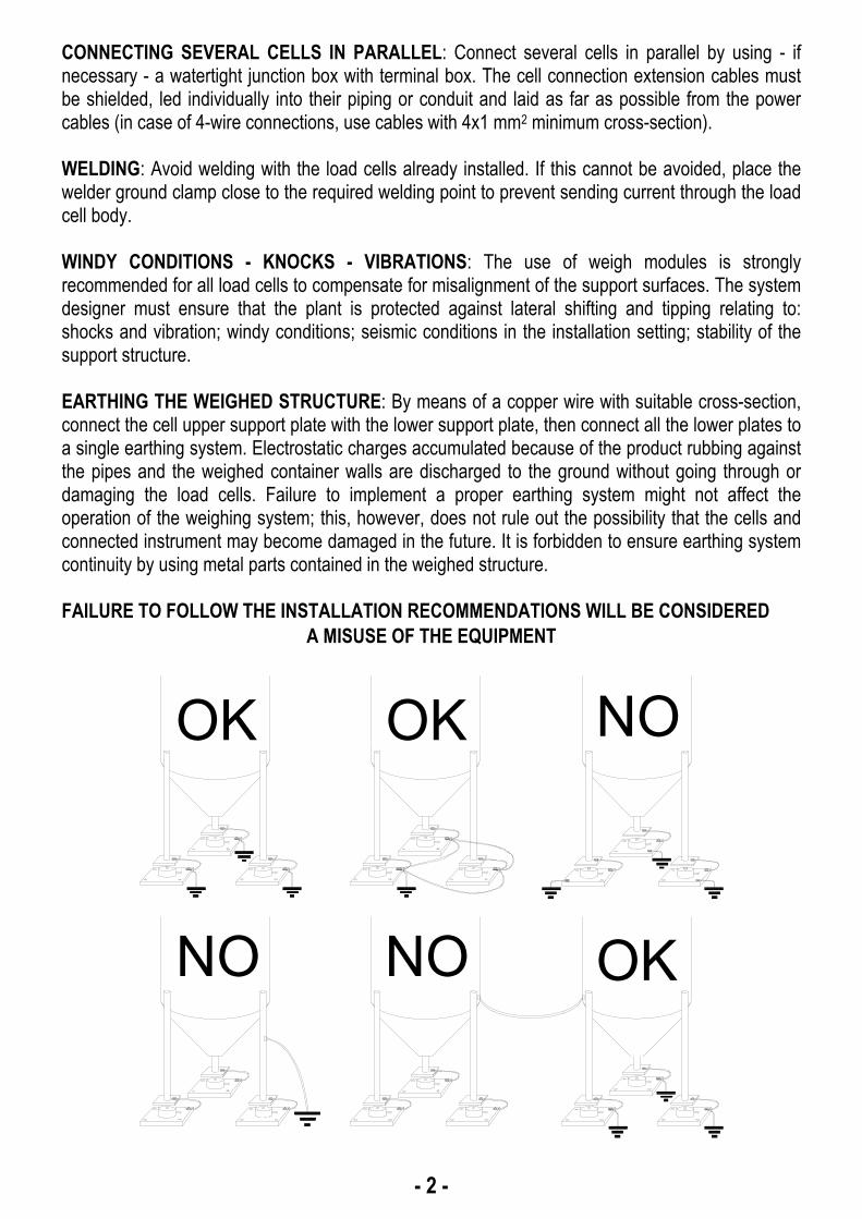
CONNECTING SEVERAL CELLS IN PARALLEL: Connect several cells in parallel by using - if necessary - a watertight junction box with terminal box. The cell connection extension cables must be shielded, led individually into their piping or conduit and laid as far as possible from the power cables (in case of 4-wire connections, use cables with 4x1 mm2 minimum cross-section). WELDING: Avoid welding with the load cells already installed. If this cannot be avoided, place the welder ground clamp close to the required welding point to prevent sending current through the load cell body. WINDY CONDITIONS - KNOCKS - VIBRATIONS: The use of weigh modules is strongly recommended for all load cells to compensate for misalignment of the support surfaces. The system designer must ensure that the plant is protected against lateral shifting and tipping relating to: shocks and vibration; windy conditions; seismic conditions in the installation setting; stability of the support structure. EARTHING THE WEIGHED STRUCTURE: By means of a copper wire with suitable cross-section, connect the cell upper support plate with the lower support plate, then connect all the lower plates to a single earthing system. Electrostatic charges accumulated because of the product rubbing against the pipes and the weighed container walls are discharged to the ground without going through or damaging the load cells. Failure to implement a proper earthing system might not affect the operation of the weighing system; this, however, does not rule out the possibility that the cells and connected instrument may become damaged in the future. It is forbidden to ensure earthing system continuity by using metal parts contained in the weighed structure. FAILURE TO FOLLOW THE INSTALLATION RECOMMENDATIONS WILL BE CONSIDERED
A MISUSE OF THE EQUIPMENT
OK OK
NO NO
NO
OK

- 3 -
LOAD CELL INPUT TEST (QUICK ACCESS)
From the weight display, press ▲ for 3 seconds; the response signal of the load cells is displayed, expressed in mV with four decimals.
LOAD CELL TESTING Load cell resistance measurement (use a digital multimeter): - Disconnect the load cells from the instrument and check that there is no moisture in the cell
junction box caused by condensation or water infiltration. If so, drain the system or replace it if necessary.
- The value between the positive signal wire and the negative signal wire must be equal or similar to the one indicated in the load cell data sheet (output resistance).
- The value between the positive excitation wire and the negative excitation wire must be equal or similar to the one indicated in the load cell data sheet (input resistance).
- The insulation value between the shield and any other cell wire and between any other cell wire and the body of the load cell must be higher than 20 Mohm.
Load cell voltage measurement (use a digital multimeter): - Take out the load cell to be tested from underneath the container, or alternatively, lift the
container support. - Make sure that the excitation of two wires of the load cell connected to the instrument (or
amplifier) is 5 Vdc ±3%. - Measure the response signal between the positive and the negative signal wires by directly
connecting them to the tester, and make sure that it is comprised between 0 and 0.5 mV. - Apply load to the cell and make sure that there is a signal increment. IF ONE OF THE ABOVE CONDITIONS IS NOT MET, PLEASE CONTACT THE TECHNICAL ASSISTANCE SERVICE.

- 4 -
MAIN SPECIFICATIONS OF THE INSTRUMENT
Indicator with 6-wire load cell input installable on table, panel front, wall or column; 6-key membrane keypad with buzzer, real-time clock/calendar with buffer battery. Two serial ports (RS485 and RS232) for connection to: PC/PLC up to 32 instruments (max 99 with line repeaters) by ASCII or ModBus R.T.U. protocol, remote display, printer. Optional: integrated Profibus DP, DeviceNet, CANopen, Profinet IO, Ethernet/IP, Ethernet TCP/IP, Modbus/TCP output. Instruments with P, D type connectors: included switching power supply plug 24 V 450 mA, input 100÷240 VAC, 3 meters long cable. Display: Model Display Resolution Viewing area WDESK-G WINOX-G
STN transmissive graphic LCD, white on blue, backlit 240x64 pixel 133x39 mm
WINOX-2G STN transmissive graphic LCD, white on blue, backlit
240x128 pixel 128x75 mm
Dimensions:
WDESK Version Max. encumbrance Drilling
P - PG9 cable gland IP67 protection rating Power supply included
122x226x164 mm (connectors included)
96x186 mm
Q - Removable terminal strip (panel front) Front panel IP67 protection rating
122x226x152 mm (connectors included) 92x186 mm
D – D-Sub tray IP40 protection rating Power supply included
122x226x189 mm (connectors included)
96x186 mm
X - Atex cable gland
IP67 Atex II3GD version (areas 2 -22) IP67 protection rating
122x226x164 mm (connectors included)
96x186 mm

- 5 -
Wall installation with bracket (can also be installed on table)
122x230x250 mm ca. (bracket included)
WINOX Type of connectors Max. encumbrance Drilling
P - PG9 cable gland IP68 protection rating Power supply included
206x286x108 mm (connectors included)
160x248 mm
Q - Removable terminal strip (panel front) Front panel IP68 protection rating
206x286x96 mm (connectors included)
160x248 mm
D – D-Sub tray (table) IP40 protection rating Power supply included
206x286x85 mm (connectors included)
X - Atex cable gland
IP68 Atex II3GD version (areas 2 -22) IP68 protection rating
206x286x108 mm (connectors included)
160x248 mm
Wall installation with bracket (can also be installed on table)
206x286x187 mm ca. (bracket included)

- 6 -
BUFFER BATTERY The instrument is equipped with an internal battery that allows to keep active the internal clock even in the event of power failure.
At the first start and after long periods of inactivity, leave the instrument on for at least 12 hours to fully charge the battery.
AFTER A BLACKOUT
After a blackout the instrument DOES NOT come on again automatically, you have to press ON. To guarantee an automatic restart after a blackout, disable the ON key as follows: - disconnect power supply and open the instrument; - identify flat connectors coming from the keypad on the main board; - extract the 4-pole connector; - short-circuit the following pins using the unused jumper inside the instrument:
▫ WDESK: the two pins further in compared to the main board (see picture to the left); ▫ WINOX: the two outer pins compared to the main board (see picture to the right);
- connect the 4-pole flat to the two pins still free complying with initial orientation.
WDESK WINOX

- 7 -
TECHNICAL SPECIFICATIONS
POWER SUPPLY and CONSUMPTION (VDC) 12/24 VDC ±10%; 6 W (standard)
POWER SUPPLY and CONSUMPTION (VAC) 115/230 VAC; 50-60 Hz; 6 VA (optional only for WDESK – WINOX-P)
NO. OF LOAD CELLS IN PARALLEL and SUPPLY max 8 (350 ohm); 5 VDC / 120 mA LINEARITY / ANALOG OUTPUT LINEARITY < 0.01% F.S.; < 0.01% F.S. THERMAL DRIFT / ANALOG OUTPUT THERMAL DRIFT < 0.0005% F.S./°C; < 0.003% F.S./°C A/D CONVERTER 24 bit (16000000 points) MAX DIVISIONS (with measurement range: ±10 mV = sens. 2 mV/V)
±999999
MEASUREMENT RANGE ±39 mV MAX SENSITIVITY OF USABLE LOAD CELLS ±7 mV/V MAX CONVERSIONS PER SECOND 300 conversions/second DISPLAY RANGE ±999999 NO. OF DECIMALS / DISPLAY INCREMENTS 0÷4 / x 1 x 2 x 5 x 10 x 20 x 50 x 100 DIGITAL FILTER / READINGS PER SECOND 0.012÷7 s / 5÷300 Hz
RELAY LOGIC OUTPUTS N. 5 - max 115 VAC; 150 mA (N. 4 – analog output version)
LOGIC INPUTS N. 3 - optoisolated 5 - 24 VDC PNP (N. 2 – analog output version)
SERIAL PORTS RS485, RS232 BAUD RATE 2400, 4800, 9600, 19200, 38400, 115200 HUMIDITY (non condensing) 85% STORAGE TEMPERATURE -30°C +80°C WORKING TEMPERATURE -20°C +60°C OPTOISOLATED ANALOG OUTPUT (OPTIONAL) 16 bit - 65535 divisions
0÷20 mA; 4÷20 mA (max 300 ohm); 0÷10 V; 0÷5 V; ±10 V; ±5 V (min 10 kohm)
RELAY LOGIC OUTPUTS N. 5 - max 30 VAC, 60 VDC; 150 mA (N. 4 – analog output version)
WORKING TEMPERATURE -20°C +50°C Equipment to be powered by 12-24 Vdc LPS or Class 2 power source.
RELE6PROD TECHNICAL SPECIFICATIONS POWER SUPPLY and CONSUMPTION (VDC) 12/24 VDC (standard) ±10%; 2 W POWER SUPPLY and CONSUMPTION (VAC) 115/230 VAC (optional); 50-60 Hz; 1.5 VA RELAY LOGIC OUTPUTS N. 8 - max 115 VAC; 2 A HUMIDITY (non condensing) 85% STORAGE TEMPERATURE -30°C +80°C WORKING TEMPERATURE -20°C +60°C

- 8 -
ELECTRICAL CONNECTIONS
BASIC INFORMATION
- It is recommended that the power supply negative pole be grounded (WDESK-D, WINOX:
connect the earthing system to the dedicated external terminal ). - It is possible to supply up to eight 350 ohm load cells or sixteen 700 ohm load cells. - For 4-wire load cells, make a jumper between EX- and REF- and between EX+ and REF+. - Connect terminal “– SUPPLY” to the RS485 common of the connected instruments in the event
that these receive alternating current input or that they have an optoisolated RS485. - In case of an RS485 network with several devices it is recommended to activate the 120 ohm
termination resistance on the two devices located at the ends of the network, as described in section RS485 SERIAL CONNECTION.
- Option E/EC: selects the first 12 formulas.
WIRING DIAGRAM: 3 PRODUCTS
(1) ANALOG OUTPUT OPTION
12
EC OPTION
3
21
7685
4
10
11
9
8
E OPTION
1 32 4 5 6 7 14119 10 1312 1615
4to instrument
Current output:max load 300 ohm
Voltage output:min load 10 kohm
Buttons not included in the supply
1 2 3 4 5 6 7 8 9 10 11 12 13 14 15 16 17 18 19 20 21 22 23 24
12-24 VDCsupply
RS485
IN 3
INPUTsupply
5-24 VDC
to IN
CO
MM
MO
N (R5)
SLO
W/A
LAR
M
to E
-EC
OP
T. - +
SU
PP
LY +
SU
PP
LY -
TX
D
RX
D(R
1) P
RO
D. 1
OU
T C
OM
MO
N
ST
OP
EX
CIT
AT
ION
-
RE
F./S
EN
SE
+
IN C
OM
MO
N
EX
CIT
AT
ION
+
RE
F./S
EN
SE
-
SIG
NA
L -
SIG
NA
L +
RS232
LOAD CELLS6-WIRE load cell
connection
INPUTSsupply
5-24 VDC
OUTPUTSmax 115 VAC
150 mA
2 3 4
+ 0
-10
VD
C
- C
OM
MO
N
+ 0
-20
4-20
mA
19 20 21 22 23 24
EX
CIT
. -
EX
CIT
. +
SIG
NA
L -
SIG
NA
L +
4-WIRE load cell connection
8
8 4
+ -
(R2)
PR
OD
. 2
(R3)
PR
OD
. 3
(R4)
CY
CLE
EN
D
WARNING!115 V / 230 V OPTIONS(WDESK-P / WINOX-P)
L115/230
VACN
7SUPPLYOUT + 24 VDC
OUTPUT8
SUPPLYOUT -
) The IN3 input can have the following
functions: - APPROVAL (default) - SEMI-AUTOMATIC ZERO - NET/GROSS WEIGHT
(1) If the analog output is present (ANALOG OUTPUT OPTION) the following are no longer available: - IN3 input - SLOW/ALARM output - E/EC options
WARNING: connect power supply specified on the plate found on the back of the instrument. In 115 V and 230 V versions, terminals “+ SUPPLY” and “– SUPPLY” generate continuous voltage at 24 Vdc only to be used as power supply for instrument inputs.

- 9 -
WIRING DIAGRAM: 6 PRODUCTS R
EL
E6
PR
OD
24V
RELAY
17
IN C
OM
PRO
D.5
NO
PRO
D.4
CO
M
PRO
D.4
NO
PRO
D.3
CO
M
PRO
D.3
NO
PRO
D.2
CO
M
PRO
D.2
NO
PRO
D.1
CO
M
PRO
D.1
NOIN
4
IN1
IN2
IN3
8L 3N 4 5 6 7
RELAYRELAYRELAY
13109 1211 1514 16
P2P1
POWER
P4P3
PRO
D.6
CO
M
CYC
LE E
ND
CO
M
CYC
LE E
ND
NO
PRO
D.6
NO
PRO
D.5
CO
M
RELAY RELAY RELAY
201918 2221 23 24
FCP6P5 LE
RELAY
12
-24
VD
C-+
SLO
W C
OM
SLO
W N
O
12
34
56
78
910
1112
1314
1516
1718
1920
2122
2324
12-2
4 V
DC
sup
ply
RS
485
IN 3 to IN COMMMONALARM (5 VDC OUT) R5
to E-EC OPT.
-
+
SUPPLY +SUPPLY -
TXD
RXD
R1
OUT COMMON (5 VDC)
STOP
EXCITATION -
REF./SENSE +
IN COMMON
EXCITATION +
REF./SENSE -
SIGNAL -
SIGNAL +
RS
232
LO
AD
CE
LL
S6-
WIR
E l
oad
cel
lco
nn
ecti
on
INP
UT
Ssu
pply
5-2
4 V
DC
+-
R2
R3
R4
RE
LE
6PR
OD
MO
DU
LE
R1
R2
R3
R4
OU
TP
UT
S
II
I0
PR
OD
. 1
0I
I0
PR
OD
. 2
I0
I0
PR
OD
. 3
00
I0
PR
OD
. 4
II
00
PR
OD
. 5
0I
00
PR
OD
. 6
I0
00
CY
CLE
EN
D
XX
XI
SLO
W
(1) A
NA
LOG
OU
TP
UT
OP
TIO
N
12
EC
OP
TIO
N
3 21
76
85
4
10 119
8
E O
PT
ION
13
24
56
71
41
19
101
31
21
61
5
4to
inst
rum
ent
Cur
rent
ou
tput
:m
ax lo
ad
300
ohm
Vol
tage
out
put:
min
load
10
kohm
But
tons
not
incl
uded
in th
e su
pply
23
4
+ 0-10 VDC
- COMMON
+ 0-20 4-20 mA
1920
2122
2324
EXCIT. -
EXCIT. +
SIGNAL -
SIGNAL +4
-WIR
E lo
ad c
ell c
onne
ctio
n
8 84
INPUT supply5-24 VDC
L1
15/2
30V
AC
N 7S
UP
PL
YO
UT
+24
VD
CO
UT
PU
T8
SU
PP
LY
OU
T -
RE
LE6P
RO
D -
115V
/-23
0V
WA
RN
ING
! 11
5 V
/ 23
0 V
OP
TIO
NS
(WD
ES
K-P
/ W
INO
X-P
)
115
/230
VA
C
LN
3
LN
WE
IGH
T IN
DIC
AT
OR
)
The
IN3
inpu
t can
hav
e th
e fo
llow
ing
func
tions
: -
APP
RO
VAL
(def
ault)
-
SEM
I-AU
TOM
ATI
C Z
ERO
-
NET
/GR
OSS
WEI
GH
T (1
) If
the
anal
og o
utpu
t is
pres
ent (
ANAL
OG
OU
TPU
T O
PTIO
N)
the
follo
win
g ar
e no
long
er a
vaila
ble:
-
IN3
inpu
t -
ALA
RM
out
put
- E/
EC o
ptio
ns
WA
RN
ING
: co
nnec
t pow
er s
uppl
y sp
ecifi
ed o
n th
e pl
ate
foun
d on
the
back
of t
he
inst
rum
ent.
In 1
15 V
and
230
V v
ersi
ons,
ter
min
als
“+ S
UPP
LY”
and
“– S
UPP
LY”
gene
rate
con
tinuo
us v
olta
ge a
t 24
Vdc
onl
y to
be
used
as
pow
er s
uppl
y fo
r in
stru
men
t inp
uts.

- 10 -
WIRING DIAGRAM: 14 PRODUCTS R
EL
E6
PR
OD
24V
RELAY
17
IN C
OM
PRO
D.5
NO
PRO
D.4
CO
M
PRO
D.4
NO
PRO
D.3
CO
MPR
OD
.3 N
O
PRO
D.2
CO
M
PRO
D.2
NO
PRO
D.1
CO
M
PRO
D.1
NOIN
4
IN1
IN2
IN3
8L 3N 4 5 6 7
RELAYRELAYRELAY
13109 1211 1514 16
P2P1
POWER
P4P3
PRO
D.6
CO
M
CYC
LE E
ND
CO
M
CYC
LE E
ND
NO
PRO
D.6
NO
PRO
D.5
CO
M
RELAY RELAY RELAY
201918 2221 23 24
FCP6P5 LE
P11
9PR
OD
.11
NO
PRO
D.1
0 C
OM
PRO
D.1
0 N
O
PRO
D.9
CO
MPR
OD
.9 N
O
PRO
D.8
CO
M
PRO
D.8
NO
PRO
D.7
CO
M
PRO
D.7
NO
21 3 4 5 76 8
P8P7 P10P9
PRO
D.1
2 C
OM
PRO
D.1
4 C
OM
PRO
D.1
4 N
O
PRO
D.1
3 C
OM
PRO
D.1
3 N
O
PRO
D.1
2 N
O
PRO
D.1
1 C
OM
10 11 12 1413 15 16
P13P12
POWER
P14
RELAY
RELAYRELAYRELAYRELAYRELAYRELAYRELAYRELAY
RE
LE
6PR
OD
MO
DU
LE
R1
R2
R3
R4
OU
TP
UT
S
II
I0
PR
OD
. 1
0I
I0
PR
OD
. 2
I0
I0
PR
OD
. 3
00
I0
PR
OD
. 4
II
00
PR
OD
. 5
0I
00
PR
OD
. 6
I0
00
CY
CLE
EN
D
RE
LE
14P
RO
D M
OD
UL
E
R1
R2
R3
R4
OU
TP
UT
S
00
0I
PR
OD
. 7
I0
0I
PR
OD
. 8
0I
0I
PR
OD
. 9
II
0I
PR
OD
. 10
00
II
PR
OD
. 11
I0
II
PR
OD
. 12
0I
II
PR
OD
. 13
II
II
PR
OD
. 14
12-2
4V
DC
-+R
EL
E1
4P
RO
D
12
34
56
78
910
1112
1314
1516
1718
1920
2122
2324
12-2
4 V
DC
su
pp
ly
RS
485
IN 3 to IN COMMMONSLOW / ALARM (5 VDC OUT) R5
to E-EC OPT.
-
+
SUPPLY +SUPPLY -
TXD
RXD
R1
OUT COMMON (5 VDC)
STOP
EXCITATION -
REF./SENSE +
IN COMMON
EXCITATION +
REF./SENSE -
SIGNAL -
SIGNAL +
RS
232
LO
AD
CE
LLS
6-W
IRE
load
ce
llc
on
ne
ctio
n
INP
UT
Ssu
pply
5-2
4 V
DC
+-
R2
R3
R4
INPUT supply5-24 VDC
12
EC
OP
TIO
N
3 21
76
85
4
10 119
8
E O
PT
ION
13
24
56
714
11
910
13
12
16
15
4to
inst
rum
ent
But
tons
no
t in
clud
ed in
the
supp
ly
8 84
(1) A
NA
LOG
OU
TP
UT
OP
TIO
N
Cur
rent
out
put:
max
load
300
ohm
Vol
tage
out
put:
min
load
10
kohm
23
4
+ 0-10 VDC
- COMMON
+ 0-20 4-20 mA
1920
2122
2324
EXCIT. -
EXCIT. +
SIGNAL -
SIGNAL +
4-W
IRE
loa
d c
ell c
on
nect
ion
L11
5/23
0V
AC
N 7S
UP
PLY
OU
T +
24 V
DC
OU
TP
UT
8S
UP
PLY
OU
T -
RE
LE
6P
RO
D -
115V
/-2
30V
WA
RN
ING
! 11
5 V
/ 23
0 V
OP
TIO
NS
(WD
ES
K-P
/ W
INO
X-P
)
115/
230
VA
C
LN
3
LN
WE
IGH
T I
ND
ICA
TO
R
)
The
IN3
inpu
t can
hav
e th
e fo
llow
ing
func
tions
: -
APP
RO
VAL
(def
ault)
-
SEM
I-AU
TOM
ATI
C Z
ERO
-
NET
/GR
OSS
WEI
GH
T (1
) If
the
anal
og o
utpu
t is
pres
ent (
ANAL
OG
OU
TPU
T O
PTIO
N) t
he fo
llow
ing
are
no lo
nger
ava
ilabl
e:
- IN
3 in
put
- SL
OW
/ALA
RM
out
put
- E/
EC o
ptio
ns
WA
RN
ING
: co
nnec
t po
wer
sup
ply
spec
ified
on
the
plat
e fo
und
on t
he b
ack
of t
he i
nstru
men
t. In
115
V a
nd 2
30 V
ve
rsio
ns,
term
inal
s “+
SU
PPLY
” an
d “–
SU
PPLY
” ge
nera
te
cont
inuo
us v
olta
ge a
t 24
Vdc
only
to b
e us
ed a
s po
wer
sup
ply
for i
nstru
men
t inp
uts.

- 11 -
CHANGING VOLTAGE 115VAC / 230VAC (WDESK) Access instrument board by removing the six bottom screws and work on the welding side: join the red points using a stiff wire.
230 Vac
230
115
115
115 Vac
230
115
115
KEY TO P, Q, X TYPE CONNECTORS Terminal Signal Terminal Signal
1 14
OUTPUT No. 4: - CYCLE END (3 PROD. version) - connect to RELE6PROD module (6/14 PROD. versions)
2
INPUT No. 3: selectable (+VDC min 5 V max 24 V) otherwise: +ANALOG OUTPUT (0÷20 o 4÷20 mA)
15 OUTPUT COMMON
3
OUTPUT No. 5: - SLOW/ALARM (3/14 PROD. versions) - ALARM (6 PROD. version) otherwise: +ANALOG OUTPUT (0÷10 V)
16 INPUT No. 1: START (+VDC min 5 V max 24 V)
4 E/EC OPTION otherwise: -ANALOG OUTPUT COMMON
17 INPUT No. 2: STOP (+VDC min 5 V max 24 V)
5 RS485: - 18 INPUT COMMON (-VDC 0 V)
6 RS485: + 19 -LOAD CELL EXCITATION (-Exc) LOAD CELL SHIELD
7
+SUPPLY (12/24 VDC) 115/230 VAC optional version: +OUTPUT (24 VDC)*
20 +LOAD CELL EXCITATION (+Exc)

- 12 -
8
-SUPPLY (12/24 VDC) RS232, RS485: SHIELD, GND E/EC OPTION: GND 115/230 VAC optional version: -OUTPUT (24 VDC)* RS232, RS485: SHIELD, GND E/EC OPTION: GND
21 +LOAD CELL REF/SENSE
9 RS232: TXD 22 -LOAD CELL REF/SENSE 10 RS232: RXD 23 -LOAD CELL SIGNAL (-Sig)
11
OUTPUT No. 1: - PRODUCT 1 (3 PROD. version) - connect to RELE6PROD module (6/14 PROD. versions)
24 +LOAD CELL SIGNAL (+Sig)
12
OUTPUT No. 2: - PRODUCT 2 (3 PROD. version) - connect to RELE6PROD module (6/14 PROD. versions)
L PHASE (115/230 VAC optional ver.)
13
OUTPUT No. 3: - PRODUCT 3 (3 PROD. version) - connect to RELE6PROD module (6/14 PROD. versions)
N NEUTRAL (115/230 VAC optional ver.)
GROUND (115/230 VAC optional ver.) *) Use only as power supply for instrument inputs.
To access the terminal strip on the WDESK instruments with cable glands, you need to remove the bottom of the instrument unscrewing the six screws.
KEY TO D TYPE CONNECTORS
Connector Pin Signal Internal terminal
Internal colour
P1
Power supply
+SUPPLY (12/24 VDC) 7 red
-SUPPLY (12/24 VDC) 8 black
D1 Female
Load cell
1 -LOAD CELL EXCITATION (-Exc) 19 black 2 -LOAD CELL REF/SENSE 22 yellow 3 4 5 LOAD CELL SHIELD 19 6 +LOAD CELL EXCITATION (+Exc) 20 red 7 +LOAD CELL REF/SENSE 21 blue 8 -LOAD CELL SIGNAL (-Sig) 23 white 9 +LOAD CELL SIGNAL (+Sig) 24 green

- 13 -
D3 Male
IN/OUT
Analog output E/EC option
1
OUTPUT No.1 (max 24 V): - PRODUCT 1 (3 PROD. version) - connect to RELE6PROD module (6/14 PROD. versions)
11 yellow
2
OUTPUT No.2 (max 24 V): - PRODUCT 2 (3 PROD. version) - connect to RELE6PROD module (6/14 PROD. versions)
12 blue
3
OUTPUT No.3 (max 24 V): - PRODUCT 3 (3 PROD. version) - connect to RELE6PROD module (6/14 PROD. versions)
13 white
4
OUTPUT No.4 (max 24 V): - CYCLE END (3 PROD. version) - connect to RELE6PROD module (6/14 PROD. versions)
14 green
5
OUTPUT No.5 (max 24 V): - SLOW/ALARM (3/14 PROD. version) - ALARM (6 PROD. version) otherwise:
+ANALOG OUTPUT (0-10 V)
3 orange
6 OUTPUT COMMON (max 24 V) 15 purple 7 INPUT No.1: START (+VDC min 5 V max 24 V) 16 grey 8 INPUT No.2: STOP (+VDC min 5 V max 24 V) 17 pink
9
INPUT No. 3: selectable (+VDC min 5 V max 24 V) otherwise:
+ANALOG OUTPUT (0÷20 o 4÷20 mA)
2 brown
10 INPUT COMMON (-VDC 0 V) 18 white/blue
11
E/EC OPTION otherwise:
-ANALOG OUTPUT COMMON
4 red
12 E/EC OPTION: GND ANALOG OUTPUT: SHIELD
8 black
13 14 15
D4 Male
RS232 serial port
1 2 RS232: RXD 10 yellow 3 RS232: TXD 9 blue 4 5 RS232: SHIELD, GND 8 black 6 7 8 9

- 14 -
D5 Male
RS485 serial
port with 24 VDC
output
1 +OUTPUT (24 VDC)* 7 red 2 -OUTPUT (24 VDC)* 8 black 3 4 RS485: + 6 yellow 5 RS485: SHIELD, GND 8 black 6 RS485: - 5 blue 7 RS485: - 5 blue 8 9 RS485: + 6 yellow
*) Not available if the instrument is battery powered.
Use only if the instrument is connected to the provided 24 VDC power supply. Maximum load: 5 W.
KEY TO “RELE6PROD” MODULE TERMINALS
Terminal Signal D3 pin C9 pin 1 +SUPPLY (12/24 VDC)
2 -SUPPLY (12/24 VDC) 3 4 INSTRUMENT OUTPUT COMMON 6 5 5 INSTRUMENT OUTPUT No. 1 1 1 6 INSTRUMENT OUTPUT No. 2 2 2 7 INSTRUMENT OUTPUT No. 3 3 3 8 INSTRUMENT OUTPUT No. 4 4 4 9 PRODUCT 1 NO
10 PRODUCT 1 COM 11 PRODUCT 2 NO 12 PRODUCT 2 COM 13 PRODUCT 3 NO 14 PRODUCT 3 COM 15 PRODUCT 4 NO 16 PRODUCT 4 COM 17 PRODUCT 5 NO 18 PRODUCT 5 COM 19 PRODUCT 6 NO 20 PRODUCT 6 COM 21 CYCLE END NO 22 CYCLE END COM 23 SLOW NO (6 PRODUCT version) 24 SLOW COM (6 PRODUCT version)

- 15 -
KEY TO “RELE14PROD” MODULE TERMINALS
Terminal Signal 1 PRODUCT 7 NO 2 PRODUCT 7 COM 3 PRODUCT 8 NO 4 PRODUCT 8 COM 5 PRODUCT 9 NO 6 PRODUCT 9 COM 7 PRODUCT 10 NO 8 PRODUCT 10 COM 9 PRODUCT 11 NO 10 PRODUCT 11 COM 11 PRODUCT 12 NO 12 PRODUCT 12 COM 13 PRODUCT 13 NO 14 PRODUCT 13 COM 15 PRODUCT 14 NO 16 PRODUCT 14 COM
- 16 -
INTRODUCTION TO THE OPERATION
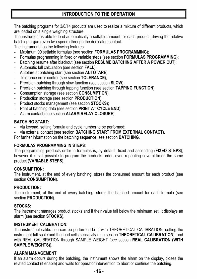
The batching programs for 3/6/14 products are used to realize a mixture of different products, which are loaded on a single weighing structure. The instrument is able to load automatically a settable amount for each product, driving the relative batching organ (even two-speed) through the dedicated contact. The instrument has the following features: - Maximum 99 settable formulas (see section FORMULAS PROGRAMMING); - Formulas programming in fixed or variable steps (see section FORMULAS PROGRAMMING); - Batching resume after blackout (see section RESUME BATCHING AFTER A POWER CUT); - Automatic fall calculation (see section FALL); - Autotare at batching start (see section AUTOTARE); - Tolerance error control (see section TOLERANCE); - Precision batching through slow function (see section SLOW); - Precision batching through tapping function (see section TAPPING FUNCTION); - Consumption storage (see section CONSUMPTION); - Production storage (see section PRODUCTION); - Product stocks management (see section STOCKS); - Print of batching data (see section PRINT AT CYCLE END); - Alarm contact (see section ALARM RELAY CLOSURE);
BATCHING START: - via keypad, setting formula and cycle number to be performed; - via external contact (see section BATCHING START FROM EXTERNAL CONTACT). For further information on the batching sequence, see section BATCHING.
FORMULAS PROGRAMMING IN STEPS: The programming products order in formulas is, by default, fixed and ascending (FIXED STEPS); however it is still possible to program the products order, even repeating several times the same product (VARIABLE STEPS).
CONSUMPTION: The instrument, at the end of every batching, stores the consumed amount for each product (see section CONSUMPTION).
PRODUCTION: The instrument, at the end of every batching, stores the batched amount for each formula (see section PRODUCTION).
STOCKS: The instrument manages product stocks and if their value fall below the minimum set, it displays an alarm (see section STOCKS).
INSTRUMENT CALIBRATION: The instrument calibration can be performed both with THEORETICAL CALIBRATION, setting the instrument full scale and the load cells sensitivity (see section THEORETICAL CALIBRATION), and with REAL CALIBRATION through SAMPLE WEIGHT (see section REAL CALIBRATION (WITH SAMPLE WEIGHTS)).
ALARM MANAGEMENT: If an alarm occurs during the batching, the instrument shows the alarm on the display, closes the related contact (if enable) and waits for operator intervention to abort or continue the batching.
- 17 -
KEYS AND SYMBOLS FUNCTIONS
KEYS
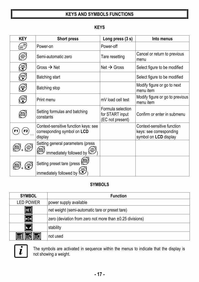
KEY Short press Long press (3 s) Into menus
Power-on Power-off
Semi-automatic zero Tare resetting Cancel or return to previous menu
Gross Net Net Gross Select figure to be modified
Batching start Select figure to be modified
Batching stop Modify figure or go to next menu item
Print menu mV load cell test Modify figure or go to previous menu item
Setting formulas and batching constants
Formula selection for START input (EC not present)
Confirm or enter in submenu
…
Context-sensitive function keys: see corresponding symbol on LCD display
Context-sensitive function keys: see corresponding symbol on LCD display
+
Setting general parameters (press
immediately followed by )
+ Setting preset tare (press
immediately followed by )
SYMBOLS
SYMBOL Function
LED POWER power supply available
net weight (semi-automatic tare or preset tare)
zero (deviation from zero not more than ±0.25 divisions)
stability
not used
The symbols are activated in sequence within the menus to indicate that the display is not showing a weight.

- 18 -
MENU MAP
Into menus changes are applied right after pressing the ENTER key (no further confirmation is required).
SYSTEM PARAMETERS
*: only for 3 and 14 products versions

- 19 -
BATCHING CONSTANTS
- 20 -
LCD GRAPHIC DISPLAY
BASIC INFORMATION
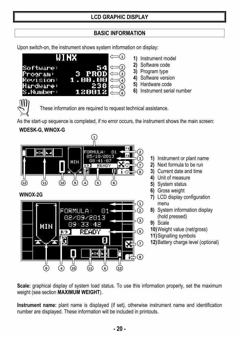
Upon switch-on, the instrument shows system information on display:
1) Instrument model 2) Software code 3) Program type 4) Software version 5) Hardware code 6) Instrument serial number
These information are required to request technical assistance.
As the start-up sequence is completed, if no error occurs, the instrument shows the main screen:
WDESK-G, WINOX-G
1) Instrument or plant name 2) Next formula to be run 3) Current date and time 4) Unit of measure 5) System status 6) Gross weight 7) LCD display configuration
menu 8) System information display
(hold pressed) 9) Scale 10) Weight value (net/gross) 11) Signalling symbols 12) Battery charge level (optional)
WINOX-2G
Scale: graphical display of system load status. To use this information properly, set the maximum weight (see section MAXIMUM WEIGHT). Instrument name: plant name is displayed (if set), otherwise instrument name and identification number are displayed. These information will be included in printouts.
2
3
4
5
6
1
1112 10 69 4
3
7
8
2
1
5
3
10 11 129
5
7
8
2
1
64

- 21 -
LCD GRAPHIC DISPLAY CONFIGURATION
From the main screen press the function key to enter the LCD display configuration menu; use the keys ▲, ▼, ENTER, ESC or the function keys to move within menus:
1) Unit of measure 2) Gross weight symbol 3) Setpoint status and value 4) Gross weight value 5) Number of setpoint class*
- LANGUAGE - CONTRAST - PLANT NAME (the name set will be displayed and printed) - FORMULAS NAME (the name set will be displayed and printed) - PRODUCTS NAME (the name set will be displayed and printed) - MSG JOLLY (messages customization, it appears only after having selected the
JOLLY language) - CONSUMPTION (see section CONSUMPTION) - PRODUCTION (see section PRODUCTION) - STOCKS (see section STOCKS) - LOT (the name set will be displayed and printed)
LANGUAGE SETTING The instrument supports several languages to show LCD display messages.
> LANGUAGE - ITALIANO (default) - ENGLISH - FRANÇAIS - ESPAÑOL - JOLLY
“JOLLY” language: allows to customize the text of messages; it can also be loaded onto the instrument (via PC) specific character sets to write messages in other languages. Selecting the JOLLY language another submenu appears:
> MSG JOLLY - EDIT MSG (edit messages) - RESET MSG (restore messages to their default values in english)
3
4
5
2
1

- 22 -
CUSTOMIZING MESSAGES OF LCD GRAPHIC DISPLAY The instrument allows to edit messages in the following way:
> PLANT NAME
> FORMULAS NAME
> PRODUCTS NAME
> LOT
> MSG JOLLY* > EDIT MSG (only after having selected the JOLLY language) *) allows to edit all display messages Select the message to edit, the following screen appears:
1) Message box 2) Selected character 3) Symbols selection area 4) Selected symbol 5) Return to previous character 6) Delete selected character 7) Confirm changes 8) Go to next character
Use the alphanumeric keys to enter the required characters. Symbols selection area: move cursor within the symbols selection area using the following keys:
- Press ▲ or ▼ to move vertically; - Press ◄ or ► to move horizontally; - Press ENTER to confirm selected symbol and go to next character; - Press ESC to cancel changes and return to previous screen;
Selected character: the character currently being edited is indicated by the blinking cursor inside the message box; Selected symbol: the currently selected symbol is indicated by the blinking cursor inside the symbols selection area.
6
7
8
5
3
1
2
4

- 23 -
INSTRUMENT COMMISSIONING
To turn on the instrument press ON. To turn it off press OFF for about 3 seconds: when appears release the key. After a blackout the instrument DOES NOT come on again automatically, you have to press ON. To guarantee an automatic restart after a blackout, disable the ON key (see section AFTER A BLACKOUT). Upon switch-on, the display shows in sequence: - → (ONLY in case of approved program); - instrument model (e.g.: or ); - followed by the software code (e.g.: ); - program type: (base); ; ; ; ; ; (no active program); - followed by the software version (e.g.: ); - followed by the hardware code (e.g.: ); - serial number (e.g.: ); Check that the display shows the weight and that when loading the load cells there is an increase in weight. If there is not check and verify the connections and correct positioning of the load cells. - If the instrument has already been theoretical CALIBRATED (plant system identification tag
present on the instrument and on the cover: load cell’s rated data already entered): ▫ Reset to zero (see section TARE WEIGHT ZERO SETTING) ▫ Check the calibration with sample weights and correct the indicated weight if necessary (see
section REAL CALIBRATION (WITH SAMPLE WEIGHTS)). - If the instrument HAS NOT BEEN CALIBRATED (missing plant system identification tag)
proceed with calibration: ▫ If load cells data are unknown, follow the procedure in section REAL CALIBRATION (WITH
SAMPLE WEIGHTS) ▫ Enter the rated data of load cells following the procedure given in section THEORETICAL
CALIBRATION ▫ Reset to zero (see section TARE WEIGHT ZERO SETTING) ▫ Check the calibration with sample weights and correct the indicated weight if necessary (see
section REAL CALIBRATION (WITH SAMPLE WEIGHTS)). - If you use the analog output, set the desired analog output type and the full scale value (see
section ANALOG OUTPUT). - If you use serial communication, set the related parameters (see section SERIAL
COMMUNICATION SETTING). - Set instrument’s clock with current date and time (see section DATE AND TIME SETTING) Required settings for the first batching: - Access the Batching Constants menu and set the minimum weight value (see section MINIMUM
WEIGHT); - Access the Formulas menu and set the formula 01 (see section FORMULAS PROGRAMMING); - Start the batching by pressing the START button or by closing the START contact

- 24 -
PROGRAMMING OF SYSTEM PARAMETERS
From the weight display, press simultaneously keys MENU and ESC to access the parameter setting. MENU/ENTER: to enter a menu/confirm the data entry. ▲ ▼: to modify the displayed value or menu item. ◄ ►: to select a new figure. ESC: to cancel and return to the previous menu.
THEORETICAL CALIBRATION
This function allows the load cell rated values to be set. To perform the theoretical calibration set the following parameters in sequence: - (Default: ): The system full scale is given by one cell capacity multiplied by the
number of cells used. Example: 4 cells of 1000 kg FULL SCALE = 1000 x 4 = 4000. The instrument is supplied with a theoretical full scale value corresponding to 10000. To restore factory values, set 0 as full scale.
- (Default: 2.00000 mV/V): Sensitivity is a load cell rated parameter expressed in mV/V. Set the average sensitivity value indicated on the load cells. It’s possible to set a value between 0.50000 and 7.00000 mV/V. Example of 4-cell system with sensitivity: 2.00100, 2.00150, 2.00200, 2.00250; enter 2.00175, calculated as (2.00100 + 2.00150 + 2.00200 + 2.00250) / 4.
- : The division (resolution) is the minimum weight increment value which can be displayed. It is automatically calculated by the system according to the performed calibration, so that it is equal to 1/10000 of full scale. It can be changed and be variable between 0.0001 and 100 with x1 x2 x5 x10 increments.
- By modifying the theoretical full scale, the sensitivity or divisions, the real calibration is
cancelled and the theoretical calibration only is considered valid. - If the theoretical full scale and the recalculated full scale in real calibration (see section
REAL CALIBRATION (WITH SAMPLE WEIGHTS)) are equal, this means that the calibration currently in use is theoretical; if they are different, the calibration in use is the real calibration based on sample weights.
- By modifying the theoretical full scale, the sensitivity or divisions and all the system’s parameters containing a weight value will be set to default values.

- 25 -
TARE WEIGHT ZERO SETTING
This menu may also be accessed directly from the weight display, holding down the 0 key for 3 seconds. Perform this procedure after having set the THEORETICAL CALIBRATION data. Use this function to set to zero the weight of the empty system after commissioning and then later on to compensate zero variations due to the presence of product residues. Procedure: - Confirm the message (Zero) by pressing ENTER. - The weight value to be set to zero is displayed. In this phase all of the symbols are flashing. - Confirming once again, the weight is set to zero (the value is stored to the permanent memory). - Press ▲ to display the value of the total weight reset by the instrument, given by the sum of all
of the previous zero settings.
ZERO VALUE MANUAL ENTRY
WARNING: Perform this procedure only if it’s not possible to reset the weighed structure tare, for example because it contains product that can not be unloaded. Set in this parameter the estimated zero value (from 0 to max 999999; default: 0).
REAL CALIBRATION (WITH SAMPLE WEIGHTS)
After having performed the THEORETICAL CALIBRATION and TARE WEIGHT ZERO SETTING, this function allows correct calibration to be done using sample weights of known value and, if necessary, any deviations of the indicated value from the correct value to be corrected. Load onto the weighing system a sample weight, which must be at least 50% of the maximum quantity to be weighed.By confirming the message the flashing value of the weight currently on the system is displayed. In this phase all of the symbols are off. Adjust the value on display by using the arrow keys if necessary. After confirming, the new set weight will appear with all the symbols flashing.After an additional confirmation, the message will be restored and by repeatedly pressing the key ESC the weight will once again be displayed.

- 26 -
Example: for a system of maximum capacity 1000 kg and 1 kg division, two sample weights are available, one of 500 kg and the other one of 300 kg. Load both weights onto the system and correct the indicated weight to 800. Now remove the 300 kg weight, the system must show 500; remove the 500 kg weight, too; the system must read zero. If this does not happen, it means that there is a mechanical problem affecting the system linearity. WARNING: identify and correct any mechanical problems before repeating the procedure.
- If theoretical full scale and recalculated full scale in real calibration are equal, it means that the theoretical calibration is currently in use; otherwise, the real calibration based on sample weights is in use.
- If the correction made changes the previous full scale for more than 20%, all the parameters with settable weight values are reset to default values.
LINEARISATION OPTION ON MAX 5 POINTS: It is possible to perform a linearisation of the weight repeating the above-described procedure up to a maximum of five points, using five different sample weights. The procedure ends by pressing the ESC button or after entering the fifth value; at this point it will no longer be possible to change the calibration value, but only to perform a new real calibration. To perform a new calibration, should return to the weight display and then re-entering into the calibration menu.By pressing ▲ after having confirmed the sample weight that has been set, the full scale appears, recalculated according to the value of the maximum sample weight entered and making reference to the cell sensitivity set in the theoretical calibration ().
FILTER ON THE WEIGHT
Setting this parameter allows a stable weight display to be obtained. To increase the effect (weight more stable) increase the value (from 0 to 9, default 4). As seen in the diagram: - By confirming the message, the currently programmed filter value is displayed.- By changing and confirming the value, the weight is displayed and it will be possible to
experimentally verify its stability. - If stability is not satisfactory, confirming brings back the message and the filter may be
modified again until an optimum result is achieved.
The filter enables to stabilise a weight as long as its variations are smaller than the corresponding “response time”. It is necessary to set this filter according to the type of application and to the full scale value set.

- 27 -
FILTER VALUE Response times [ms]
Display and serial port refresh frequency
[Hz]
0 12 300 1 150 100 2 260 50 3 425 25
4 (default) 850 12.5 5 1700 12.5 6 2500 12.5 7 4000 10 8 6000 10 9 7000 5
ANTI PEAK When the weight is stable, the anti peak filter removes any sudden disturbances with a maximum duration of 1 second. Confirm the filter on the weight with ENTER and select one of the following options: - : anti peak filter enabled (default);- : anti peak filter disabled.
ZERO PARAMETERS
RESETTABLE WEIGHT SETTING FOR SMALL WEIGHT CHANGES (from 0 to max full scale; default: 300; considered decimals: 300 – 30.0 – 3.00 – 0.300): this parameter indicates the maximum weight value resettable by external contact, keypad or serial protocol.
AUTOMATIC ZERO SETTING AT POWER-ON (from 0 to max 20% of full scale; default: 0): If at switch-on the weight value is lower than the value set in this parameter and does not exceed the value, the weight is reset. By setting 0, the function is disabled ().
- 28 -
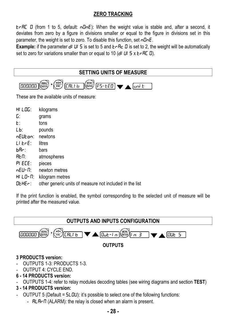
ZERO TRACKING (from 1 to 5, default: ): When the weight value is stable and, after a second, it deviates from zero by a figure in divisions smaller or equal to the figure in divisions set in this parameter, the weight is set to zero. To disable this function, set . Example: if the parameter is set to 5 and is set to 2, the weight will be automatically set to zero for variations smaller than or equal to 10 ( x ).
SETTING UNITS OF MEASURE
These are the available units of measure: : kilograms : grams : tons : pounds : newtons : litres : bars : atmospheres : pieces : newton metres : kilogram metres : other generic units of measure not included in the list If the print function is enabled, the symbol corresponding to the selected unit of measure will be printed after the measured value.
OUTPUTS AND INPUTS CONFIGURATION
OUTPUTS
3 PRODUCTS version: - OUTPUTS 1-3: PRODUCTS 1-3. - OUTPUT 4: CYCLE END. 6 - 14 PRODUCTS version: - OUTPUTS 1-4: refer to relay modules decoding tables (see wiring diagrams and section TEST) 3 - 14 PRODUCTS version: - OUTPUT 5 (Default = ): it’s possible to select one of the following functions:
- (ALARM): the relay is closed when an alarm is present.

- 29 -
- (SLOW): slow function for a precision batching. 6 PRODUCTS VERSION: - OUTPUT 5: ALARM (the relay is closed when an alarm is present)
INPUTS
- INPUT 1: START - INPUT 2: STOP- INPUT 3 (Default = ): It’s possible to select one of the following functions:
- (NET/GROSS): by closing this input for no more than one second, it’s making an operation of SEMI-AUTOMATIC TARE and the display will show the net weight. To display the gross weight again, hold the NET/GROSS input closed for 3 seconds.
- (SEMI-AUTOMATIC ZERO): by closing the input for no more than one second, the weight is set to zero (see section SEMI-AUTOMATIC ZERO (WEIGHT ZERO-SETTING FOR SMALL VARIATIONS)).
- (APPROVAL): the instrument starts the batching only after verifying that this input is closed.
SEMI-AUTOMATIC TARE (NET/GROSS)
THE SEMI-AUTOMATIC TARE OPERATION IS LOST UPON INSTRUMENT POWER-OFF.
To perform a net operation (SEMI-AUTOMATIC TARE), close the NET/GROSS input or press the TARE key for less than 3 seconds. The instrument displays the net weight (recently set to zero) preceded by the letter and the symbol NET will be activated. To display the gross weight again, keep the NET/GROSS input closed or press TARE for 3 seconds. This operation can be repeated many times by the operator to allow the loading of several products. Example: Put the box on the scale, the display shows the box weight; press TARE, the display shows the net weight to zero; introduce the product in the box, the display shows the product weight. This operation can be repeated several times. The semi-automatic tare operation is not allowed if the gross weight is zero.

- 30 -
PRESET TARE (SUBTRACTIVE TARE DEVICE)
It is possible to manually set a preset tare value to be subtracted from the display value provided that the ≤ max weight condition is verified. By default the instrument shows the last programmed preset tare value: to apply it press ▲ and then ENTER. After setting the tare value, going back to the weight display, the display shows the net weight (subtracting the preset tare value) and the NET symbol lights up to show that a tare has been entered. To delete a preset tare and return to gross weight display, hold down TARE for about 3 seconds or keep the NET/GROSS input (if any) closed for the same length of time (3 seconds). The preset tare value is set to zero. The NET symbol is turned off when the gross weight is displayed once again.
- IF A SEMI-AUTOMATIC TARE (NET) IS ENTERED, IT IS NOT POSSIBLE TO ACCESS THE ENTER PRESET TARE FUNCTION.
- IF A PRESET TARE IS ENTERED, IT’S STILL POSSIBLE TO ACCESS THE SEMI-AUTOMATIC TARE (NET) FUNCTION. THE TWO DIFFERENT TYPES OF TARE ARE ADDED.
ALL THE SEMI-AUTOMATIC TARE (NET) AND PRESET TARE FUNCTIONS WILL BE LOST WHEN THE INSTRUMENT IS TURNED OFF.
SEMI-AUTOMATIC ZERO (WEIGHT ZERO-SETTING FOR SMALL VARIATIONS) By closing the SEMI-AUTOMATIC ZERO input, the weight is set to zero; alternatively, by pressing the 0 key for less than 3 seconds, the message is displayed for 3 seconds, by pressing ENTER the weight is set to zero. This function is only allowed if the weight is lower than the value (see section RESETTABLE WEIGHT SETTING FOR SMALL WEIGHT CHANGES), otherwise the alarm appears and the weight is not set to zero.

- 31 -
ANALOG OUTPUT(ONLY FOR INSTRUMENTS WHERE THIS OPTION IS AVAILABLE)
- : it selects the analog output type (4÷20 mA, 0÷20 mA, 0÷10 V, 0÷5 V, ±10 V, ±5 V;
default: 4÷20 mA).
For the output ±10 V and ±5 V the soldered jumper SW1 must be closed: ▫ open the instrument; ▫ locate on the analog board, which is mounted perpendicular to the main board, the
soldered jumper SW1 highlighted in the picture below:
▫ close the jumper shorting the pads with a drop of tin. - : choice of a weight followed by the analog output: gross () or net (). If the net
function is not active, the analog output varies according to gross weight. - : set the weight value for which you wish to obtain the minimum analog output value.
Only set a value different from zero if you wish to limit the analog output range; for instance: for a full scale value of 10000 kg you require an 4 mA signal at 5000 kg and 20 mA at 10000 kg, in this case, instead of zero, set 5000 kg.
- : set the weight value for which you wish to obtain the maximum analog output value; it
must correspond to the value set in the PLC program (default: calibration full scale). E.g.: if I am using a 4÷20 mA output and in the PLC program I wish to have 20 mA = 8000 kg, I will set the parameter to 8000.
- : analog output correction to zero: if necessary adjust the analog output, allowing the PLC to indicate 0. The sign “-“ can be set for the last digit on the left. E.g.: if I use a 4÷20 mA output and, with the minimum analog setting, the PLC or tester read 4.1 mA, I must set the parameter to 3.9 to obtain 4.0 on the PLC or tester.
- : correction of analog output to full scale: if necessary permit modification of the analog output by allowing PLC to indicate the value set in the parameter . E.g. if I am using a 4÷20 mA output with the analog set to full scale and the PLC or tester reads 19.9 mA, I must set the parameter to 20.1 to get 20.0 on the PLC or tester.

- 32 -
Minimum and maximum values which can be set for zero and full scale corrections: ANALOG OUTPUT TYPE Minimum Maximum 0÷10 V -0.150 10.200 0÷5 V -0.150 5.500 ±10 V -10.300 10.200 ±5 V -5.500 5.500 0÷20 mA -0.200 22.000 4÷20 mA -0.200 22.000
NOTE: the analog output may also be used in the opposite manner, i.e. the weight setting that corresponds to the analog zero () may be greater than the weight set for the analog full scale (). The analog output will increase towards full scale as the weight decreases; the analog output will decrease as the weight increases. For example: = 10000 = 0 analog output 0÷10 V Weight = 0 kg analog output = 10 V Weight = 5000 kg analog output = 5 V Weight =10000 kg analog output = 0 V

- 33 -
SERIAL COMMUNICATION SETTING
- / : communication port.
- : it disables any type of communication (default). - : MODBUS-RTU protocol; possible addresses: from 1 to 99 (see Communication
protocols manual). - : continuous weight transmission protocol to RIP5/20/60, RIP50SHA, RIPLED series
remote displays; the remote display shows the net weight or gross weight according to its settings (set: = , = , = ).
- : continuous weight transmission protocol to RIP675, RIP6125C series remote displays; the remote display shows the net weight or gross weight according to its settings (set: = , = , = ).
- : continuous weight transmission protocol to RIP675, RIP6125C series remote displays (set: = , = , = ).
When the remote display is set to gross weight: - if the instrument displays the gross weight, the remote display shows the gross weight. - if the instrument shows the net weight, the remote display shows the net weight
alternated with the message . - : printer.
- : transmission speed (2400, 4800, 9600, 19200, 38400, 115200; default:
9600). - : instrument address (from 1 to 99; default: 1). - : delay in milliseconds which elapses before the instrument replies (from 0
to 200 ms; default: 0). - :
- : no parity (default). - : even parity. - : odd parity.
- : stop bit (1 – 2; default: 1). - : number of blank lines between one printout and the next. - : printing of custom heading from PC ( – ; default: ). - : connected printer type:
- - - - (generic serial printer)
For more information about protocols and methods of communication, request the proper manual to technical assistance.

- 34 -
RS232 SERIAL COMMUNICATION
DB9-F
5
3
2INSTRUMENT
RS232 TXD PCRS232 RXD
GND
RS485 SERIAL COMMUNICATION
INSTRUMENT
RS485 +RS485 -
max 500 m
RS
485
+
3 2
5
PC
RS
232
RX+
RX-
TX-TX+
CONVLAU
24 VDC+
-
0TX
RX
VIN RS485 +RS485 -
RS
485
-
RS
485
+
RS
485
-
RS
485
+
RS
485
-
GN
D
GN
D
GN
D
INSTRUMENT INSTRUMENT
If the RS485 network exceeds 100 metres in length or baud-rate over 9600 are used, two terminating resistors are needed at the ends of the network. Two 120 ohm resistors must be connected between the “+” and “–” terminals of the line, on the terminal strip of the furthest instruments. Should there be different instruments or converters, refer to the specific manuals to determine whether it is necessary to connect the above-mentioned resistors.
DIRECT CONNECTION BETWEEN RS485 AND RS232 WITHOUT CONVERTER Since a two-wire RS485 output may be used directly on the RS-232 input of a PC or remote display, it is possible to implement instrument connection to an RS-232 port in the following manner: INSTRUMENT RS232 RS485 – → RXD RS485 + → GND
This type of connection allows A SINGLE instrument to be used in a ONE WAY mode.

- 35 -
ALARM RELAY CLOSURE
In 3 and 14 products versions it is necessary to set OUT5 = ALARM (see section OUTPUTS AND INPUTS CONFIGURATION).
The ALARM relay closing can be enabled or disabled for each of the following alarms: approval contact ();formula not programmed (); maximum weight exceeded (); minimum weight (); no increase in weight (); no decrease in weight (); tolerance (); fall (); the PC did not read the batching data (). : in presence of alarm, the relay is closed (default) : the relay is not closed even in the presence of alarm.
TEST
- Input Test:
: ensure that for each open input is displayed, is displayed when the input is closed. - Output Test:
: setting ensure that the corresponding output opens. Setting ensure that the corresponding output closes. Refer to the following tables to activate the relay of various products (only 6 and 14 products versions) RELE6PROD MODULE RELE14PROD MODULE R1 R2 R3 R4 OUTPUTS R1 R2 R3 R4 OUTPUTS I I I 0 PROD.1 0 0 0 I PROD.7 0 I I 0 PROD.2 I 0 0 I PROD.8 I 0 I 0 PROD.3 0 I 0 I PROD.9 0 0 I 0 PROD.4 I I 0 I PROD.10 I I 0 0 PROD.5 0 0 I I PROD.11 0 I 0 0 PROD.6 I 0 I I PROD.12 I 0 0 0 CYCLE END 0 I I I PROD.13 X X X I SLOW I I I I PROD.14
- E/EC Option Test:
: It shows the formula selected by the E/EC option, if the option is not present or is not active, the message is displayed.
- Analog Output Option Test: : It allows the analog signal to range between the minimum and the maximum values starting from the minimum. : current output test. : voltage output test.

- 36 -
- Millivolt Test: : displays the load cell response signal in mV with four decimals.
ENERGY SAVING
- : back-lighting on; - : back-lighting off; - : back-lighting goes off after about one minute of no activity; pressing a key or a weight
change turns it on again.
DATE AND TIME SETTING
Selecting the item in the main menu, access is obtained to the date and time display menu. Pressing ENTER several times scrolls through days - months – years and hours – minutes; by pressing the keys ◄ and ► the figure to change can be selected; by pressing the keys ▲ and ▼ or using the numerical keypad, the figure can be changed; pressing ENTER you can confirm and go to the next menu item.
OPERATION SETTINGS
: maximum number of products and steps selectable in formula (example: if the version in use is the 6 products and the parameter is set to "4", you can set the products from 1 to 4 and at most 4 steps for each formula). By changing the value, all formulas are deleted.
It is possible to set: -from 1 to 3 for 3 products version -from 1 to 6 for 6 products version -from 1 to 14 for 14 products version
(Default:): formulas setting in variable or fixed steps. By changing the value, all formulas are deleted.
- : products and quantities can be set in formulas in the desired order, even repeating several times the same product (VARIABLE STEPS).
- : products batching sequence is not adjustable, only quantities can be set (FIXED STEPS).

- 37 -
: Select the switch conditions from the opening of the batched product to the following or to the CYCLE END closing.
- (Default: ): time set in constants (). - (Default: ): START input closure or ENTER key pressure. - (Default: ): stable weight.
(Default: ): Select the batching resume mode after a power failure.
- : (Automatic) at the power restore, appears for 3 seconds, after which the batching resumes from the point of interruption.
- : (Manual) at the power restore appears, press ENTER to resume the batching or press ESC to stop it.
INFO MENU
: active options are displayed.

- 38 -
PROGRAMMING OF BATCHING CONSTANTS
From weight display press MENU, then press ▲ several times until is displayed and confirm. MENU/ENTER: to enter a menu/confirm the data entry. ▲ ▼: to modify the displayed value or menu item. ◄ ►: to select a new figure. ESC: to cancel and return to the previous menu.
MINIMUM WEIGHT (from 0 to max full scale; default: 10): minimum weight, value at which the scale is considered empty. Batching start is only allowed if the weight is lower than this value, during the unloading phase the CYCLE END contact will be opened when the weight reaches this value and after the safe emptying time is over.
MAXIMUM WEIGHT (from 0 to max full scale; default: 0): settable and displayable maximum weight. If the displayed weight exceeds the maximum weight by 9 divisions, the message is displayed; if in the formulas programming the weight value set is greater than this value, the message is displayed and the value will not be stored. By setting 0, the function is disabled ().
SAFE EMPTYING TIME (from 0.0 to max 999.9 seconds; default 5.0): time that is necessary for a perfect emptying of the scale. The instrument waits for this time during the unloading phase (CYCLE END closed), after reaching the minimum weight and before opening the CYCLE END contact to obtain a perfect emptying of the scale. By setting 0, the function is disabled ().
WAITING TIME (from 0.0 to max 999.9 seconds; default 5.0): time between the end batching of one product and the following one. By setting 0, the function is disabled ().
NO PRODUCT LOAD TIME (from 0.0 to max 999.9 seconds; default: 0.0): this parameter allows the product control

- 39 -
during batching. if there is no product load, the instrument waits for a set duration of time before activating the alarm . By setting 0, the function is disabled ().
NO PRODUCT UNLOAD TIME (from 0.0 to max 999.9 seconds; default: 0.0): this parameter allows the product control during the unloading phase (cycle end). If there is no product extraction, the instrument waits for a set duration of time before activating the alarm . By setting 0, the function is disabled (). WARNING: The control is only actuated after unloading of the product has started (the weight must decrease by at least 10 divisions).
FALL By FALL it means the correction of the product amount in fall after the batching STOP. This amount is in addition to the product already batched causing inaccuracy. The instrument is able to anticipate the batching STOP, to reduce this uncertainty, with two possible ways:
- AUTOMATIC fall: the instrument automatically calculates the fall; - MANUAL fall: the instrument applies the fall set by the operator;
WARNING: Setting a value of WAITING TIME () such that the weight is stable at the end of the batching, otherwise the update of the AUTOMATIC fall is not correct.
(from 0 to 1; default: 0): it’s possible to select the automatic or the manual fall.
- = 0: MANUAL fall - = 1: AUTOMATIC fall
(from 0 to maximum weight; default: 0): in this parameter it is possible to set the fall value for each product (only if = 0) or to display and/or to modify the fall value calculated automatically by the instrument (only if = 1).
TOLERANCE
(from 0 to maximum weight; default: 0): Adjustable parameter for each product that defines how much the batched weight value can deviate from the one set in formula. If the batched weight is higher or lower than the amount to be batched, for a value greater than the tolerance, the instrument closes the ALARM contact. Press ENTER to continue the batching. Example: if a PRODUCT = 1000 value is set and a TOLERANCE = 100 value is set, the batched weight must not be lower than 900 or higher than 1100 to allow the instrument to continue the batching process. By setting 0, the function is disabled ().
- 40 -
SLOW (from 0 to maximum weight; default: 0): adjustable parameter for each product. By slow value we mean the value that, when subtracted from the weight set, minus the fall value, starts the batching slow phase (closing the relative contact). If the value set is higher than the weight to be batched, batching will be all in slow phase. By setting 0, the function is disabled (). Esempio: If PRODUCT = 100, SLOW = 15 and FALL = 10, he slow phase starts when the weight reaches 75.
TAPPING FUNCTION In the event that the batching instrument is not equipped with the speed “slow” it is possible to use this function to slow down the product batching in the final phase (through opening and closing cycles of the PRODUCT contact) and to increase the accuracy. Set in parameter the product amount you want to batch with the tapping function enabled. SLOW ON (from 0 to max 9.9; default: 0): time in which the PRODUCT relay remains closed during the SLOW phase. By setting 0, the function is disabled (). SLOW OFF (from 0 to max 9.9; default: 0): time in which the PRODUCT relay remains open during the SLOW phase. By setting 0, the function is disabled ().
AUTOTARE (from 0 to 1; default: 1): autotare enabling (automatic tare at the batching start). - : autotare disabled (). - : autotare enabled This operation is possible only if the gross weight is lower than the minimum weight (), otherwise the alarm message is displayed.
AUTOTARE DELAY (from 0 to max 99.9; default: 0): the instrument waits for this time, after the starting of the formula, before performing the autotare and starting the batching. By setting 0, the function is disabled ().

- 41 -
PRINT AT CYCLE END (Default ): function enabling to print batching data at cycle end. - : print enabled - : print disabled
CHECKING PC PRESENCE (Default: ): check for a PC connected to the instrument. - : PC presence check active; the instrument checks for a PC every 10 seconds. If no PC
presence is detected, the instrument will display an alarm signal alternated with the weight value.
- : PC presence check not active. WARNING: The check is active only if selected the Modbus protocol.
WAITING CONFIRMATION FROM PC (SLAVE) (Default: ): waiting for confirmation of record batching data from PC. - : check enabled; the instrument waits for the PC to read the batching data, before starting
another batching. In case of recording failure, the instrument displays an alarm . - : check disabled; at cycle end, the instrument will not wait for data recording on PC before
performing another batching.
SWITCHING OF THE ALARM/SLOW RELAY ON WEIGHT (from 0 to max full scale; Default: ): by setting a value different from zero (), the ALARM/SLOW contact does not switch over in case of alarm/slow, but behaves as a SETPOINT contact; the relay closes when the weight reaches the value set in this parameter.

- 42 -
FORMULAS PROGRAMMING
Select the formula that you wish to program. It is possible to set max 99 formulas. FIXED STEPS ( = , see section OPERATION SETTINGS): It is only possible to set the quantity of product that you wish to batch, products batching sequence is not adjustable.
VARIABLE STEPS ( = , see section OPERATION SETTINGS): It is possible to set the step number, the product number and the quantity of product that you wish to batch.
Example: (: step number; : product number). An attempt to set a quantity higher than the maximum weight () set in the batching constants, the message is displayed.
1) Selected formula 2) Step number 3) Product number 4) Weight values
DELETING FORMULAS
Confirm with ENTER the prompt, to delete one formula enter the formula number, to delete all formulas enter 00 (), confirm with ENTER, you will be prompted to confirm (), to delete confirm again with ENTER otherwise press ESC to cancel the command.
3
42
1

- 43 -
BATCHING
Note: In case of alarm, the batching may be canceled by pressing the ESC button or by closing the STOP input.
After having selected the formula and set the desired number of batching cycles, the first batching cycle starts as follows: 1. The instrument will ensure that:
- the formula has been programmed, otherwise it will display the alarm . - the amount set in the formula does not exceed the set maximum weight (), otherwise
the message is displayed. - IN3 input (if it is set as Approval) is closed, otherwise the message will be displayed;
close the IN3 input to start the batching. - Only if is set: the gross weight is lower than the minimum weight (), otherwise the
alarm is displayed (it is always possible to force the batching start by pressing the ENTER key).
- Only if consumptions are enabled: - If the consumed amount exceeds 999000, the message appears for a second. - If the consumed amount exceeds 999999, it is automatically set to zero.
- Only if production is enabled: - If the batched amount exceeds 9990000, the message appears for a second. - If the batched amount exceeds 9999999, the amount is automatically set to zero.
2. Once the above listed conditions are met, the batching of first product programmed in formula is started; if the time is set and the product is not loaded for at least 20 divisions during this time interval, the relative alarm is displayed.
3. The number of the product to be batched (e.g. ) is displayed for 1 second and then the net weight; the product relay closes;
4. Only if is set: once the value set for that product has been reached, minus the fall and slow values, the SLOW contact closes (if foreseen); if tapping values have been set, the product contact carries out opening and closing cycles according to and times;
5. Once the value set for that product has been reached, minus any fall value, the product contact is opened interrupting product flow;
6. After the contact opening, the system shows the weight preceded by the letter and waits: - Only if = : The waiting time has elapsed (). - Only if = : The START input has been closed or the ENTER key has been
pressed. - Only if = : The weight is stable.
7. If the tolerance () is set and the batched quantity is lower than the set quantity minus this value, is made only one attempt of finishing re-start, in order to improve the batching precision. In such a case, the PRODUCT contact is closed and returns to step 5, otherwise the alarm appears. If instead, the batched quantity is greater than the set amount plus this value, the alarm appears. Press ENTER to cancel the alarm and go on with the batching.
8. Consumption/production/stocks are stored (if enabled);

- 44 -
9. If another product to be batched has been set in the formula, the instrument starts batching the new product and you return to point 3;
10. If there are no more products to be batched in the formula, the system enters the cycle end phase: - The CYCLE END contact is closed; - The display shows the weight preceded by the letter ; - Only if = : batching data (with date and time) are printed;
11. At the beginning of the product extraction, if the time is set and the product is not extracted by at least 20 divisions within this interval of time, the alarm message will be displayed.
12. The system ends the batching (opening of the CYCLE END contact) only after verifying that: - The weight is lower than the minimum weight (); - The safe emptying time has elapsed ();
13. Only if = : the instrument waits for data recording on PC, before being available for a new batching.
If several batching cycles have been set the instrument starts a new cycle.
BATCHING START FROM EXTERNAL CONTACT It is possible to select the required formula via an external selector switch. After selecting the formula, close the START external contact for at least 0.5 seconds and, verified the conditions indicated in section BATCHING, the instrument will perform the selected formula batching. If there is no the formula selection switch (E/EC options), the latest formula entered via the keypad will be batched, or it’s possible to set the required formula in the following menu: press the MENU key for 3 seconds, will be displayed, set the required formula number using the arrow keys and confirm with ENTER. At batching start, the set formula will be performed. If 00 is set, the latest formula set via keypad will be recalled.
If at the end of the batching, the START contact is closed, the same batching sequence is repeated.

- 45 -
BATCHING START FOR SINGLE PRODUCT WITH AUTOMATIC STOP This function allows to batch a single product without having to set a special formula. From weight displaying press START and select the formula; select the product to batch (eg.: ) and set its amount; confirm with ENTER to perform the batching of the selected product. The instrument updates the consumptions, production and stock values (if present and enabled) and sends the data to the printer (if enabled).
BATCHING START FOR SINGLE PRODUCT WITH STOP BY KEYBOARD This function allows to batch a single product, leaving the operator the task to stop the batching. From weight displaying press START and select the formula; select the product to batch (eg.: ) and set its amount to 0; confirm with ENTER to close the relay of the selected product and start the batching; press STOP to stop it. The instrument updates the consumptions, production and stock values (if present and enabled) and sends the data to the printer (if enabled).
UNLOADING START WITH AUTOMATIC STOP This function allows to unload all the scale contents until it reaches the minimum weight. From weight displaying press START, select the formula and select the product; confirm with ENTER to close the CYCLE END relay and start the scale unloading phase; this ends after reaching the minimum weight and after the safe emptying time has elapsed.

- 46 -
DISPLAYING DURING BATCHING During the batching cycle the display shows the following screen:
WDESK-G, WINOX-G
1) Loading product number (the arrow indicates that product is loading)
2) Product level on the scale 3) Batching weight value (net or
gross) 4) Gross weight value 5) Formula number 6) Running cycle number 7) Product number and name (if
set) 8) Set value 9) System status 10) Product detail display 11) System information display
WINOX-2G
PRODUCT DETAIL DISPLAY
Hold down the key to show batching product details:
1) Formula number 2) Running step number 3) Product number 4) Set value 5) Slow value 6) Fall value 7) Tolerance value
1
2
3
4
5
6
7
7
2
8
10
11
6
5
1
3 4
9
3 42
7
10
11
6
1
9
5
8

- 47 -
BATCHING STOP - Open the START contact and close the STOP contact to stop the batching. If the START contact
is closed, the alarm is displayed. - To pause the batching at any time, press STOP, the prompt is displayed. Press ENTER
to resume the batching or press again STOP to cancel it completely.
RESUME BATCHING AFTER A POWER CUT If a blackout occurs during the batching (unloading phase included), when power comes back appears: press ENTER to resume batching from the point of interruption, press ESC to cancel the batching and return to the weight displaying.
If in constants = , when power comes back appears and after 3 seconds the batching is automatically resumed. Power failures do not cause any deletion of cycles still to be performed.

- 48 -
TOTALS MANAGEMENT
CONSUMPTION
This feature allows to store consumption of each product since the last deletion. To enable consumptions management:
> CONSUMPTION - ENABLE (select YES to enable, NO to disable)
To access consumptions data press function key:
> CONSUMPTION - DISPLAY (consumptions display) - DELETE (consumptions deletion) - PRINT (consumptions print)
Select > CONSUMPTION > DISPLAY to view the consumption list per product:
1) Date and time of last deletion 2) Products list 3) Selected product 4) Consumption
Press ▲ ▼ keys to scroll products list and related consumptions or directly select the product to be displayed: press ENTER, set product number (field ) and confirm.
3
1
2
3
4

- 49 -
PRODUCTION This feature allows to store the quantity of batched product and the number of executed cycles for each formula since the last deletion. To enable production management:
> PRODUCTION - ENABLE (select YES to enable, NO to disable)
To access production data press function key:
> PRODUCTION - DISPLAY (production display) - DELETE (production deletion) - PRINT (production print)
Select > PRODUCTION > DISPLAY to view the production list per formula:
1) Date and time of last deletion 2) Formulas list 3) Selected formula 4) Batched quantity and number of
executed cycles
Press ▲ ▼ keys to scroll formulas list and related production data or directly select the formula to be displayed: press ENTER, set formula number (field ) and confirm.
STOCKS This feature allows to manage the stocks for each product. If STOCKS value falls below MINIMUM STOCK value, the alarm is displayed. If at batching start the product quantity to be batched (quantity set in formula multiplied by number of cycles to be run) is higher than STOCKS value, the alarm is displayed. To enable stocks management:
> STOCKS - ENABLE (select YES to enable, NO to disable)
3
1
2
3
4

- 50 -
To access stocks data press function key:
> STOCKS - DISPLAY (stocks display and modification) - DELETE (stocks deletion) - PRINT (stocks print)
> MINIMUM STOCK - DISPLAY (minimum stocks display and modification) - DELETE (minimum stocks deletion) - PRINT (minimum stocks print)
Select > STOCKS > DISPLAY to view the list of available stocks per product:
1) Current date and time 2) Products list 3) Selected product 4) Available quantity
Press ▲ ▼ keys to scroll products list and related available quantities; to edit a product stock press ENTER, set product number (field ) and confirm; the display shows the following screen:
1) Value 2) Additional information 3) Value deletion 4) Value sign change 5) Selected figure
Additional information:
- PROD: product number; - QTY: quantity currently stored to be modified;
Set the value to add to or subtract from the stock currently stored using the numerical keypad or the keys ▲, ▼, ◄ and ►; press ENTER to confirm.
To view and edit the minimum stocks, select > MINIMUM STOCK > DISPLAY and proceed as for stocks.
3
1
2
3
4
5
1
2
3
4

- 51 -
ALARMS
: (only if = 1) it is displayed if, at batching start, the weight on the scale is higher
than the minimum set in constants (). Press ESC to return to the weight displaying, press ENTER to cancel the alarm and continue with the batching. If the weight comes back below to the minimum set, the batching starts.
: it is displayed when at the batching start the APPROVAL input is open (if the input 3 is set as approval; In 3 = ). Close the input to enable batching or cancel it by pressing ESC.
: it is displayed if at batching end the weight is different from the value set in formula by a value higher than tolerance. Press ENTER to cancel the alarm and continue with the batching.
: it is displayed if at batching start the fall value is higher than the product quantity to be batched. Press ESC to cancel the alarm and the batching.
: it is displayed if, at batching start, the formula recalled for running is not programmed. Press the key ESC to quit.
: it is displayed if, at batching start, the formula recalled for running exceeds the maximum weight. Press the key ESC to quit.
: it means that during batching the STOP key has been pressed, temporarily interrupting the cycle; press the ENTER key to start it again, or STOP to terminate completely the batching.
: it indicates that a power failure occurred during batching: press ESC to cancel the batching or press ENTER to resume batching again from the point of interruption.
: during the batching it indicates that the product is not loaded. It is automatically cancelled if the product increases. Press STOP twice to cancel the batching.
: during the unload (Cycle End contact closed) it indicates that the product is not extracted. It is automatically cancelled if the product decreases. Press STOP twice to cancel the unload.
: it is displayed for 3 seconds if you try to stop the batching (by pressing twice STOP or closing the related input) when the START input is closed. Open the START input to cancel the alarm.
: batching is cancelled. Press ESC to quit. If the alarm persists, contact technical assistance.
: it is displayed when there is a weight alarm and it cancels the current batching. Press ESC to go back to the weight display and check the alarm.
: the load cell is not connected or is incorrectly connected; the load cell signal exceeds 39 mV; the conversion electronics (AD converter) is malfunctioning; the load cell is a 4−wire and there are no jumpers between EX- and REF- and between EX+ and REF+.
: the weight display exceeds 110% of the full scale. : internal instrument converter failure; check load cell connections, if necessary contact
technical assistance. : the weight exceeds the maximum weight by 9 divisions. : maximum displayable value exceeded (value higher than 999999 or lower than -999999). : weight too high: zero setting not possible.
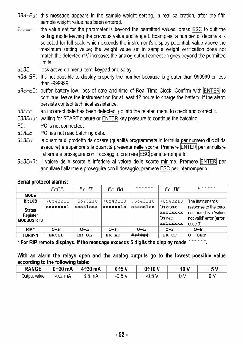
- 52 -
: this message appears in the sample weight setting, in real calibration, after the fifth sample weight value has been entered.
: the value set for the parameter is beyond the permitted values; press ESC to quit the setting mode leaving the previous value unchanged. Examples: a number of decimals is selected for full scale which exceeds the instrument's display potential; value above the maximum setting value; the weight value set in sample weight verification does not match the detected mV increase; the analog output correction goes beyond the permitted limits.
: lock active on menu item, keypad or display. : It’s not possible to display properly the number because is greater than 999999 or less
than -999999. : buffer battery low, loss of date and time of Real-Time Clock. Confirm with ENTER to
continue; leave the instrument on for at least 12 hours to charge the battery, if the alarm persists contact technical assistance.
: an incorrect date has been detected: go into the related menu to check and correct it. : waiting for START closure or ENTER key pressure to continue the batching. : PC is not connected. : PC has not read batching data. : la quantità di prodotto da dosare (quantità programmata in formula per numero di cicli da
eseguire) è superiore alla quantità presente nelle scorte. Premere ENTER per annullare l’allarme e proseguire con il dosaggio, premere ESC per interromperlo.
: il valore delle scorte è inferiore al valore delle scorte minime. Premere ENTER per annullare l’allarme e proseguire con il dosaggio, premere ESC per interromperlo.
Serial protocol alarms:
MODE Bit LSB 76543210
xxxxxxx1 76543210 xxxx1xxx
76543210 xxxxxx1x
76543210 xxxxx1xx
76543210 On gross: xxx1xxxx On net: xx1xxxxx
The instrument's response to the zero command is a 'value not valid' error (error code 3)
Status Register
MODBUS RTU
RIP * __O-F_ __O-L_ __O-F_ __O-L_ __O-F_ __O-F_HDRIP-N _ERCEL _ER_OL _ER_AD ###### _ER_OF O__SET
* For RIP remote displays, if the message exceeds 5 digits the display reads . With an alarm the relays open and the analog outputs go to the lowest possible value according to the following table:
RANGE 0÷20 mA 4÷20 mA 0÷5 V 0÷10 V ±10 V ±5 V Output value -0.2 mA 3.5 mA -0.5 V -0.5 V 0 V 0 V

- 53 -
PRINTING EXAMPLES
If the printer has been set (see section SERIAL COMMUNICATION SETTING), from the weight display press the PRINT key for less than 3 seconds: - : prints the displayed weight; - : prints the constants (minimum weight, maximum weight, etc.); - : prints one or all of the formulas; press ENTER to display , set the formula
number to be printed or “00” to print them all;
To print consumption, production and stocks data: press , enter the desired menu and select PRINT (see section TOTALS MANAGEMENT). BATCHING PRINTOUT Batching in gross weight ( = 0) ----------------------- W--- 14PROD Addr:01 FORMULA: 01 CYCLE: 1/ 1 DATE: 01/10/11 08:30:01 INIT.WEIGHT 10 kg P01 G 301: 300 kg P02 N 714: 700 kg P05 N 1025: 1000 kg TOT G 2040: 2000 kg Batching in net weight ( = 1) ----------------------- W--- 14PROD Addr:01 FORMULA: 01 CYCLE: 1/ 1 DATE: 01/10/11 08:30:01 TARE 10 kg P01 N 301: 300 kg P02 N 714: 700 kg P05 N 1025: 1000 kg TOT G 2050: 2000 kg

- 54 -
CONSTANTS PRINTOUT ----------------------- W--- 14PROD Addr:01 DATE: 01/10/11 08:30:01 CONSTANTS MIN 10 MASS 0 TIME SIC 5.0 TIME WAIT 5.0 TIME NLOAD 0.0 TIME NUNLOAD 0.0 FALL MANUAL TIME SLOWON 0.0 TIME SLOWOF 0.0 AUTOTARE YES PRINT NO PC NO SLAVE NO BLACKOUT MANUAL PR FALL TOLER SLOW 02 0 0 200 03 52 0 0 06 0 100 0 FORMULA PRINTOUT ----------------------- W--- 14PROD Addr:01 DATE: 01/10/11 08:30:01 FORMULA: 01 P01 300 kg P04 400 kg P07 1000 kg P11 400 kg

- 55 -
TOTALS PRINTOUT Minimum stocks values print ----------------------- W--- 14PROD Addr:01 DATE: 01/10/11 08:30:01 MINIMUM STOCK P01 100 kg Stocks values print ----------------------- W--- 14PROD Addr:01 DATE: 01/10/11 08:30:01 STOCK P01 8670 kg Production values print ----------------------- W--- 14PROD Addr:01 DATE: 01/10/11 08:30:01 PRODUCTION FOR CYCLE QUANTITY 01 2 784 kg FROM: 30/09/11 14:14:42 Consumptions values print ----------------------- W--- 14PROD Addr:01 DATE: 21/12/11 14:18:25 CONSUMPTION TOTAL 784 kg FROM: 30/09/11 14:14:42 If consumptions are reset to zero, it will also be printed: CONSUMPTION ERASED WEIGHT PRINTOUT ----------------------- W--- 14PROD Addr:01 DATE: 12/09/11 14:48:12 GROSS 1204 kg NET 831 kg TARE 373 kg

- 56 -
RESERVED FOR THE INSTALLER
MENU LOCKING
Through this procedure, it’s possible to block the access to any menu on the instrument. Select the menu that you wish to lock:
press ESC and ◄ simultaneously for 3 seconds, the display shows
(the left point on the text indicates that this menu item is now locked). If the operator tries
to enter this menu, the access is denied and the display shows .
MENU UNLOCKING
press ENTER and ▲ simultaneously for 3 seconds, the display shows
(the left point on the text is off to indicate that this menu item is unlocked).
TEMPORARY MENU UNLOCKING
press ▲ and ◄ simultaneously for 3 seconds: it is now possible to enter and modify all menus including those which are locked. By returning to weight display, the menu lock is restored.
DATA DELETION AND PROGRAM SELECTION
WARNING: operations must only be performed after contacting technical assistance. After each operation the display shows , press ENTER to continue. By pressing ESC the procedure is cancelled and no changes are made.
Upon instrument power-on hold down the ESC key until the display shows , then proceed as follows: CONSTANTS RESTORE (does not erase the calibration): confirm , use arrow keys to select , set code 6935 and confirm.
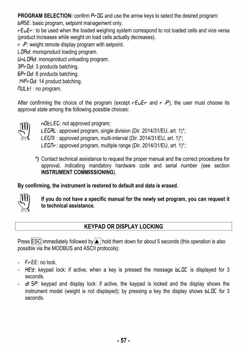
- 57 -
PROGRAM SELECTION: confirm and use the arrow keys to select the desired program: : basic program, setpoint management only. : to be used when the loaded weighing system correspond to not loaded cells and vice versa (product increases while weight on load cells actually decreases). : weight remote display program with setpoint. : monoproduct loading program. : monoproduct unloading program. : 3 products batching. : 6 products batching. : 14 product batching. : no program. After confirming the choice of the program (except and ), the user must choose its approval state among the following possible choices:
: not approved program; : approved program, single division (Dir. 2014/31/EU, art. 1)*; : approved program, multi-interval (Dir. 2014/31/EU, art. 1)*; : approved program, multiple range (Dir. 2014/31/EU, art. 1)*;
*) Contact technical assistance to request the proper manual and the correct procedures for
approval, indicating mandatory hardware code and serial number (see section INSTRUMENT COMMISSIONING).
By confirming, the instrument is restored to default and data is erased.
If you do not have a specific manual for the newly set program, you can request it to technical assistance.
KEYPAD OR DISPLAY LOCKING
Press ESC immediately followed by ▲ hold them down for about 5 seconds (this operation is also possible via the MODBUS and ASCII protocols): - : no lock. - : keypad lock: if active, when a key is pressed the message is displayed for 3
seconds. - : keypad and display lock: if active, the kaypad is locked and the display shows the
instrument model (weight is not displayed); by pressing a key the display shows for 3 seconds.


![web.ssu.ac.ir · 2020. 3. 14. · ./0102!,23+ ."-):g("& k o0]+ / 8 [fg >!0](https://img.pdfslide.net/doc/110x75/60da03a01c128744d87ca256/webssuacir-2020-3-14-010223-g-k-o0-8-fg.jpg)