Embed Size (px)
Citation preview

WDIS410 Series
Disinfection Controller
Instruction Manual
Five Boynton Road Hopping Brook Park Holliston, MA 01746 USA
TEL: 508-429-1110 FAX: 508-429-7433 WEB: www.walchem.com
WDIS410 Disinfection Controller
W A L C H E M IWAKI America Inc.

Notice © 2013 WALCHEM, Iwaki America Inc. (hereinafter “Walchem”)
Five Boynton Road, Holliston, MA 01746 USA
(508) 429-1110
All Rights Reserved
Printed in USA
Proprietary Material
The information and descriptions contained herein are the property of WALCHEM. Such
information and descriptions may not be copied or reproduced by any means, or disseminated or
distributed without the express prior written permission of WALCHEM, Five Boynton Road,
Holliston, MA 01746.
Statement of Limited Warranty
WALCHEM warrants equipment of its manufacture, and bearing its identification to be free from
defects in workmanship and material for a period of 24 months for electronics and 12 months for
mechanical parts and electrodes from date of delivery from the factory or authorized distributor
under normal use and service and otherwise when such equipment is used in accordance with
instructions furnished by WALCHEM and for the purposes disclosed in writing a the time of
purchase, if any. WALCHEM’s liability under this warranty shall be limited to replacement or
repair, F.O.B. Holliston, MA U.S.A. of any defective equipment or part which, having been returned
to WALCHEM, transportation charges prepaid, has been inspected and determined by WALCHEM
to be defective. Replacement elastomeric parts and glass components are expendable and are not
covered by any warranty.
THIS WARRANTY IS IN LIEU OF ANY OTHER WARRANTY, EITHER EXPRESS OR IMPLIED,
AS TO DESCRIPTION, QUALITY, MERCHANTABILITY, and FITNESS FOR ANY PARTICULAR
PURPOSE OR USE, OR ANY OTHER MATTER.
180367.L Mar 2013
TABLE OF CONTENTS
1.0 INTRODUCTION ...................................................................................................................... 1
2.0 SPECIFICATIONS ................................................................................................................... 2 2.1 Sensors .................................................................................................................................................. 2 2.2 Electrical: Input/Output .......................................................................................................................... 3 2.3 Mechanical (Controller) .......................................................................................................................... 3 2.4 WDIS Variables and their Limits ............................................................................................................ 4
3.0 UNPACKING & INSTALLATION .............................................................................................. 5 3.1 Unpacking the unit ................................................................................................................................. 5 3.2 Mounting the electronic enclosure ......................................................................................................... 5 3.3 Installation .............................................................................................................................................. 5 3.4 Icon Definitions ...................................................................................................................................... 7 3.5 Electrical installation ............................................................................................................................ 10
4.0 FUNCTION OVERVIEW ......................................................................................................... 13 4.1 Front Panel .......................................................................................................................................... 13 4.2 Display ................................................................................................................................................. 13 4.3 Keypad ................................................................................................................................................. 14 4.4 Access Code ........................................................................................................................................ 14 4.5 Startup ................................................................................................................................................. 14 4.6 Shut Down ........................................................................................................................................... 15
5.0 OPERATION .......................................................................................................................... 15 5.1 Main Menu ........................................................................................................................................... 15 5.2 Sensor Menu ........................................................................................................................................ 17 5.3 Control 1 - 4 Menus ............................................................................................................................. 19 5.4 4-20 mA 1 and 2 Menus (Optional) ...................................................................................................... 24 5.5 Time Menu ........................................................................................................................................... 25 5.6 Access Code Menu .............................................................................................................................. 26 5.7 Datalog Menu ....................................................................................................................................... 27 5.8 Config Menu ......................................................................................................................................... 29 5.9 Upgrade Menu ..................................................................................................................................... 30
6.0 Maintenance ........................................................................................................................... 31 6.1 Sensor Maintenance ............................................................................................................................ 31 6.2 Replacing the Fuses ............................................................................................................................ 32
7.0 TROUBLESHOOTING ........................................................................................................... 32 7.1 Error Messages .................................................................................................................................... 32
8.0 SERVICE POLICY ................................................................................................................. 34
1
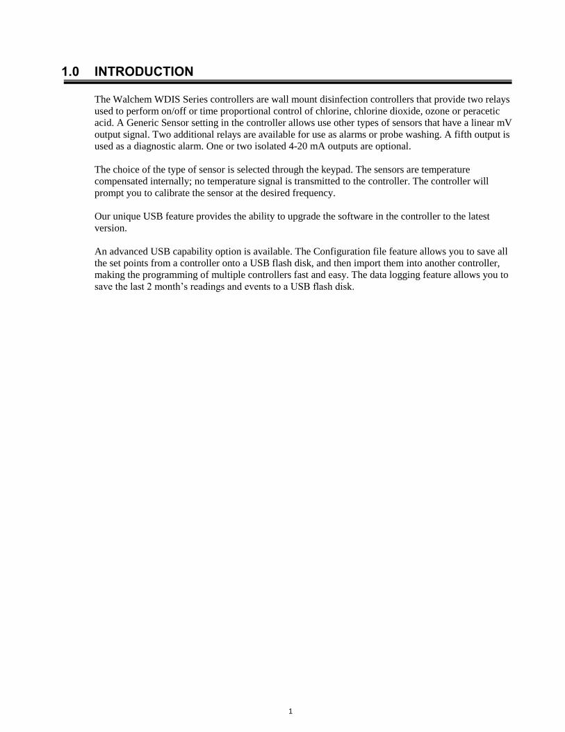
1.0 INTRODUCTION
The Walchem WDIS Series controllers are wall mount disinfection controllers that provide two relays
used to perform on/off or time proportional control of chlorine, chlorine dioxide, ozone or peracetic
acid. A Generic Sensor setting in the controller allows use other types of sensors that have a linear mV
output signal. Two additional relays are available for use as alarms or probe washing. A fifth output is
used as a diagnostic alarm. One or two isolated 4-20 mA outputs are optional.
The choice of the type of sensor is selected through the keypad. The sensors are temperature
compensated internally; no temperature signal is transmitted to the controller. The controller will
prompt you to calibrate the sensor at the desired frequency.
Our unique USB feature provides the ability to upgrade the software in the controller to the latest
version.
An advanced USB capability option is available. The Configuration file feature allows you to save all
the set points from a controller onto a USB flash disk, and then import them into another controller,
making the programming of multiple controllers fast and easy. The data logging feature allows you to
save the last 2 month’s readings and events to a USB flash disk.

2
2.0 SPECIFICATIONS
2.1 Sensors
Chlorine Dioxide Peracetic Acid Ozone Free Chlorine/Bromine
Free Chlorine/Bromine –
High pH Range
Range 0-16.75 mg/l 0-1675 mg/l 0-16.75 mg/l 0-13.25 mg/l 0-12.50 mg/l
Resolution 0.01 mg/l 1 mg/l 0.01 mg/l 0.01 mg/l 0.01 mg/l
Sensitivity Free Chlorine
(5%), Ozone
Ozone (250%),
ClO2 (100%),
H2O2 (0.5%)
ClO2 (6%) HOCl (100%)
HOBr (100%)
Ozone
ClO2 (900%)
Not for use with
isocyanuric acid or
stabilized bromine
HOCl (100%)
HOBr (100%)
Ozone
ClO2 (900%)
HOCl with isocyanuric
acid
Not for use with stabilized
bromine
Flow Rate of
Sample 30 to 100 liters/hour (0.13 to 0.44 gallons/minute)
pH Range of
Sample 1.0 – 11.0 1.0 – 7.0 2.0 – 11.0 6.8 – 8.0 4.0-12.0
Conductivity
Range of Sample 50 to 10,000 μS/cm Up to 4% NaCl 50 to 10,000 μS/cm
Response Time 30 sec 3 min 1 min 30 sec 2 min
Run-In Time 60 min 60 min 60 min 60 min 120 min
Calibration Weekly
Change
Electrolyte 6 months 3 months
Change
Membrane Cap 1 year
Electrical Power
Requirements ± 5 VDC, 5 mA maximum
Signal 0 to -2000 mVDC
Maximum Cable
Length 1000 ft (305 m)
Cable Required 2 twisted pair, 22 AWG, shielded, 35 pF/ft (Walchem 100084 or Belden 8723)
Mechanical Operating
Temperature 0 to 55°C (32 to 131°F)
0 to 50°C (32
to 122°F) 0 to 45°C (32 to 113° F)
Operating
Pressure 0 to 1 atm (0 to 14.7 psi)
Storage
Temperature 0 to 50°C (32 to 122°F)
Shelf Life 1 year
Flow Cell Inlet ¼” NPTF
Flow Cell Outlet ¾” NPTF
Wetted Materials of Construction Sensor Body PVC, Polycarbonate
Membrane Silicone PTFE Silicone
Flow Cell
Body Isoplast
O-Ring FKM

3
2.2 Electrical: Input/Output
Input Power
100-240 VAC, 50/60 Hz, 8A
Fuse: 1.0 ampere, 5 x 20 mm
Input Signals
Sensor ±2000 mV
Interlock (optional) Isolated, dry contact closure required (i.e., flow, level, etc.)
Outputs
Control 1, Control 2
(ON/OFF)
Internally powered relays switching line voltage
6 A (resistive), 1/8 HP
All relays are fused together as one group, total current for this
group must not exceed 6A
Control 3, Control 4, Alarm Dry contact relays
6 A (resistive), 1/8 HP
Note: The Alarm relay is non-programmable. Refer to the Main Menu diagram for the list of error
conditions that trigger the alarm relay.
4 - 20 mA 1 or 2 (optional) Internally powered
Fully isolated
600 Ohm max resistive load
Resolution .001% of span
Accuracy ± 1% of reading
Sensor Power ±5 VDC, 5 mA
Agency Approvals
UL ANSI/UL 61010-1:2004, 2nd Edition*
CAN/CSA C22,2 No.61010-1:2004, 2nd Edition*
CE Safety EN 61010-1:2001 2nd Edition*
CE EMC EN 61326-1:2006
Note: For EN61000-4-6, EN61000-4-3 the controller met performance criteria B.
*Class A equipment: Equipment suitable for use in establishments other than domestic, and those directly
connected to a low voltage (100-240 VAC) power supply network which supplies buildings used for
domestic purposes.
2.3 Mechanical (Controller) Enclosure Material Polycarbonate
NEMA Rating NEMA 4X
Dimensions 8.5" x 6.5" x 5.5"
Display 2 x 16 character backlit liquid crystal
Operating Ambient Temp 32 – 122°F (0 – 50°C)
Storage Temperature -20 – 180°F (-29 – 80°C)

4
2.4 WDIS Variables and their Limits
Low Limit High Limit
Sensor menu
Days Between Calibration 0 days (no reminder) 59 days
Slope (Generic only) 0.001 mV/ppm 2000 mV/ppm
Offset (Generic only) -1000 mV 1000 mV
Temperature Menu No variables
Control 1 -4 Menus
High or Low Set Point 0 ppm 20 ppm Cl2, ClO2, O3
2000 ppm PAA
99999 ppm Generic
High or Low Alarm Point 0 ppm 20 ppm Cl2, ClO2, O3
2000 ppm PAA
99999 ppm Generic
Dead Band 0.01ppm 1.99 ppm Cl2, ClO2, O3
199 ppm PAA
Proportional Band 0.01 ppm 6.99 ppm
999 ppm PAA
9999 ppm Generic
Sample Period (set in min:sec) 0:01 30:00
Time Limit (set in min:sec) 0:01 59:59 (enabled)
0=unlimited (disabled)
Hold Time (Probe Wash) 0 seconds 99 seconds
On Time (Probe Wash) 1 second 99 seconds
4-20 mA 1 and 2 Menus 4 & 20 mA Settings 0 ppm 20 ppm Cl2, ClO2, O3
2000 ppm PAA
99999 ppm Generic
Access Code Menu New
Value
0 9999
Datalog Menu (Optional) No variables
Config Menu (Optional) No variables
Upgrade Menu No variables
*Note: The Alarm relay is non-programmable. Refer to the Main Menu diagram for the list of error conditions
that trigger the alarm relay.
5
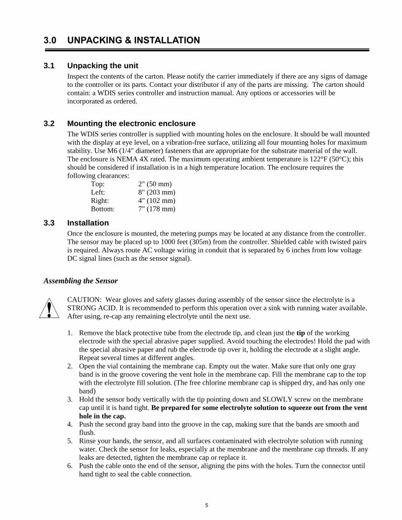
3.0 UNPACKING & INSTALLATION
3.1 Unpacking the unit
Inspect the contents of the carton. Please notify the carrier immediately if there are any signs of damage
to the controller or its parts. Contact your distributor if any of the parts are missing. The carton should
contain: a WDIS series controller and instruction manual. Any options or accessories will be
incorporated as ordered.
3.2 Mounting the electronic enclosure
The WDIS series controller is supplied with mounting holes on the enclosure. It should be wall mounted
with the display at eye level, on a vibration-free surface, utilizing all four mounting holes for maximum
stability. Use M6 (1/4" diameter) fasteners that are appropriate for the substrate material of the wall.
The enclosure is NEMA 4X rated. The maximum operating ambient temperature is 122°F (50°C); this
should be considered if installation is in a high temperature location. The enclosure requires the
following clearances:
Top: 2" (50 mm)
Left: 8" (203 mm)
Right: 4" (102 mm)
Bottom: 7" (178 mm)
3.3 Installation
Once the enclosure is mounted, the metering pumps may be located at any distance from the controller.
The sensor may be placed up to 1000 feet (305m) from the controller. Shielded cable with twisted pairs
is required. Always route AC voltage wiring in conduit that is separated by 6 inches from low voltage
DC signal lines (such as the sensor signal).
Assembling the Sensor
CAUTION: Wear gloves and safety glasses during assembly of the sensor since the electrolyte is a
STRONG ACID. It is recommended to perform this operation over a sink with running water available.
After using, re-cap any remaining electrolyte until the next use.
1. Remove the black protective tube from the electrode tip, and clean just the tip of the working
electrode with the special abrasive paper supplied. Avoid touching the electrodes! Hold the pad with
the special abrasive paper and rub the electrode tip over it, holding the electrode at a slight angle.
Repeat several times at different angles.
2. Open the vial containing the membrane cap. Empty out the water. Make sure that only one gray
band is in the groove covering the vent hole in the membrane cap. Fill the membrane cap to the top
with the electrolyte fill solution. (The free chlorine membrane cap is shipped dry, and has only one
band)
3. Hold the sensor body vertically with the tip pointing down and SLOWLY screw on the membrane
cap until it is hand tight. Be prepared for some electrolyte solution to squeeze out from the vent
hole in the cap. 4. Push the second gray band into the groove in the cap, making sure that the bands are smooth and
flush.
5. Rinse your hands, the sensor, and all surfaces contaminated with electrolyte solution with running
water. Check the sensor for leaks, especially at the membrane and the membrane cap threads. If any
leaks are detected, tighten the membrane cap or replace it.
6. Push the cable onto the end of the sensor, aligning the pins with the holes. Turn the connector until
hand tight to seal the cable connection.

6
Flow Cell Placement
Instructions for mounting the sensor into the process can vary greatly with the circumstances that are
encountered in your application. Here are some general guidelines to assist you. Refer also to the typical
installation drawings.
The sensor should be mounted such that the measuring surfaces will always stay wet. If the membrane
dries out, it will respond slowly to changing disinfectant values for 24 hours, and if dried out repeatedly,
will fail prematurely.
The flow cell should be placed on the discharge side of a circulation pump or downhill from a gravity
feed. Flow into the cell must come from the bottom side that has the ¾” x ¼” NPT reducing bushing
installed. The reducing bushing provides the flow velocity required for accurate readings and
must not be removed!
A “U” trap should be installed so that if the flow stops, the sensor is still immersed in the water. The
outlet of the flow cell must be plumbed to open atmosphere unless the system pressure is at or below 1
atmosphere. If the flow through the line cannot be stopped to allow for cleaning and calibration of the
sensor, then it should be placed in a by-pass line with isolation valves to allow for sensor removal.
Install the sensor vertically, with the measuring surface pointing down, at least 5 degrees above
horizontal. (Refer to Installation drawings)
Flow rate regulation must be done upstream from the sensor, because any flow restriction downstream
can increase the pressure above atmospheric and damage the membrane cap!
The sensor should be installed in an area where there is good solution movement and where it will
respond rapidly to chemical additions. The placement of the sensor relative to the placement of
chemical replenishment, along with the quality of the mixing, and the replenishment chemical flow rate
are critical to accurate process control.
Installing Sensor into Flow Cell
1. Assemble the flow cell as shown below from the top down. The reducer should already be installed
in the flow cell body.
2. Slide the 102586 nut over the membrane end of the sensor, followed by the 103419 top washer,
followed by the 103422 o-ring, followed by the 103419 bottom washer (concave side up), followed
by the 103421 clip ring. The clip ring must be pushed up until it snaps into the groove in the sensor
body.
3. Place the 102594 o-ring in the top o-ring groove of the 102881 flow cell body.
4. Place the sensor body into the flow cell body, and tighten the 102586 nut until it is hand-tight.
Before tightening completely, pull the sensor up until the clip ring is up against the bottom washer.
5. Insert the 191303 cable into the connector at the top of the sensor. The connector is keyed and will
only insert in one orientation.

7
Sensor Exploded View
3.4 Icon Definitions
Symbol Publication Description
IEC 417, No.5019 Protective Conductor Terminal
IEC 417, No. 5007 On (Supply)
IEC 417, No. 5008 Off (Supply)
ISO 3864, No. B.3.6 Caution, risk of electric shock
ISO 3864, No. B.3.1 Caution
DisinfectionSensor
WasherSet
p/n 103419
O-Ringp/n 103422
Nut, p/n 102586
Cable, p/n 191303
Membrane cap
Clip Ring groove
Clip ring
O-Ringp/n 102594
Body, p/n 191279-R

8
Figure 1 Typical Installation
ISOLATIONVALVE
(NORMALLYOPEN)
1
2
3
4
5
6
7
8
9
10
1/4"NPT
ROTAMETER30-100 LPH
RECIRCULATIONPUMP
FROMPROCESS
20 FT(6M)
3/4"NPT
TOPROCESS

9
Typical Installation Using Walchem Manifold
Sample Valve
Flow Control Valve
Water In
Water Out
To Open Atmosphere
Rotameter
Flow Cell
Flow Switch
Sensor

10
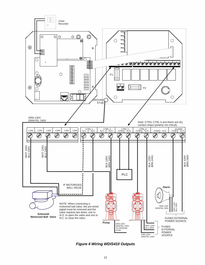
3.5 Electrical installation
The various standard wiring options are shown in figure 2. Your WDIS series controller will arrive from
the factory prewired or ready for hardwiring. Depending on your configuration of controller options,
you may be required to hardwire some or all of the input/output devices. Refer to figures 3 and 4 for
circuit board layout and wiring.
Note: when wiring the optional 4-20 mA output or a remote interlock switch, it is advisable to use
stranded, twisted, shield pair wire between 22-26 AWG. Shield should be terminated at the controller
ground stud (see figures 3 and 4).
CAUTION
1. There are live circuits inside the controller even when the power switch on the front panel is in
the OFF position! The front panel must never be opened before power to the controller is
REMOVED!
If your controller is prewired, it is supplied with a 8 foot, 18 AWG power cord with USA
style plug. A tool (#1 Phillips driver) is required to open the front panel.
2. When mounting the controller, make sure there is clear access to the disconnecting device!
3. The electrical installation of the controller must be done by trained personnel only and
conform to all applicable National, State and Local codes!
4. Proper grounding of this product is required. Any attempt to bypass the grounding will
compromise the safety of persons and property.
5. Operating this product in a manner not specified by Walchem may impair the protection
provided by the equipment.
POWER
CTRL 2
CTRL 1
FLOW SWITCH(OPTIONAL)
4-20mA #2(OPTIONAL)
ALARM
CTRL 4CTRL 3
4-20mA #1(OPTIONAL)
PLUGSENSOR
Figure 2 WDIS410 Conduit Wiring

11
Figure 3 Wiring WDIS Inputs
Power Supply(115 VAC or 230 VAC)
Contact Closure:Polarity not criticalInterlock Function
+5VT-T+
GROUND STUD
L1 L2/NGR
N 120V
GR
N/Y
EL 240V
WHT 120VBLU 240V
BLK
120V
BR
N 2
40V
IN+
IN-
+5V
-5V
-5VIN+ IN-
IN-
DIG IN 2 DIG IN 3
IN+ IN-
DIG IN 1
IN+IN-IN+
DIG IN 4
IN+ IN-
DIG IN 5
IN+ IN-
IN-
DIG
IN 2
DIG
IN 3
IN+
IN-
DIG
IN 1
IN+
IN-
IN+
DIG
IN 4
IN+
IN-
DIG
IN 5
IN+
IN-
L1 L2/N
L2 L2 L2 L2 L2 L2BLEED
N.C. N.O. N.C.
BOI 1
N.O.N.C.
FEED
N.C.
BIO 2
N.O. N.C. N.O. N.O.
ALARM
N.C. N.O.
WFCBWCDBWOZBWPAB
GR
EE
N
WH
ITE
RED
BLACK
12
Figure 4 Wiring WDIS410 Outputs
Pump
Solenoid/Motorized Ball Valve
Alarm
L1 L2/N
L2 L2 L2 L2 L2 L2BLEED
N.C. N.O. N.C.
BOI 1
N.O.N.C.
FEED
N.C.
BIO 2
N.O. N.C. N.O. N.O.
ALARM
N.C. N.O.
L2/N L2/N L2/N L2/N L2/N L2/NCTRL 1
N.C. N.O. COM.CTRL 3
N.O.N.C.CTRL 2
COMCTRL 4
N.O. COM N.O. N.O.ALARM
COM N.O.
GROUNDSTUD
WH
T 1
20
VB
LU
240
V
GRN 120VGRN/YEL 240V
IF MOTORIZEDBALL VALVE
BL
K 1
20
VB
RN
24
0V
ChartRecorder
WH
T 1
20
VB
LU
240V
GRN 120VGRN/YEL 240VTO GROUND STUD
IN+
IN-
+5
V-5
V
IN-
DIG
IN 2
DIG
IN 3
IN+
IN-
DIG
IN 1
IN+
IN-
IN+
DIG
IN 4
IN+
IN-
DIG
IN 5
IN+
IN-
F1
F2
PLC
BL
K 1
20
VB
RN
24
0V
GRN 120VGRN/YEL 240V
WHT 120VBLU 240V
FUSEDEXTERNALPOWERSOURCE
GRN 120VGRN/YEL 240V
WH
T 1
20
VB
LU
240V
BL
K 1
20V
BR
N 2
40V
FUSED EXTERNALPOWER SOURCE
Note: CTR3, CTRL 4 and Alarm are drycontact relays (polarity not critical).
NOTE: When connecting amotorized ball valve, the pre-wired pigtail must be removed and thevalve requires two wires, one toN.O. to open the valve and one toN.C. to close the valve.
13
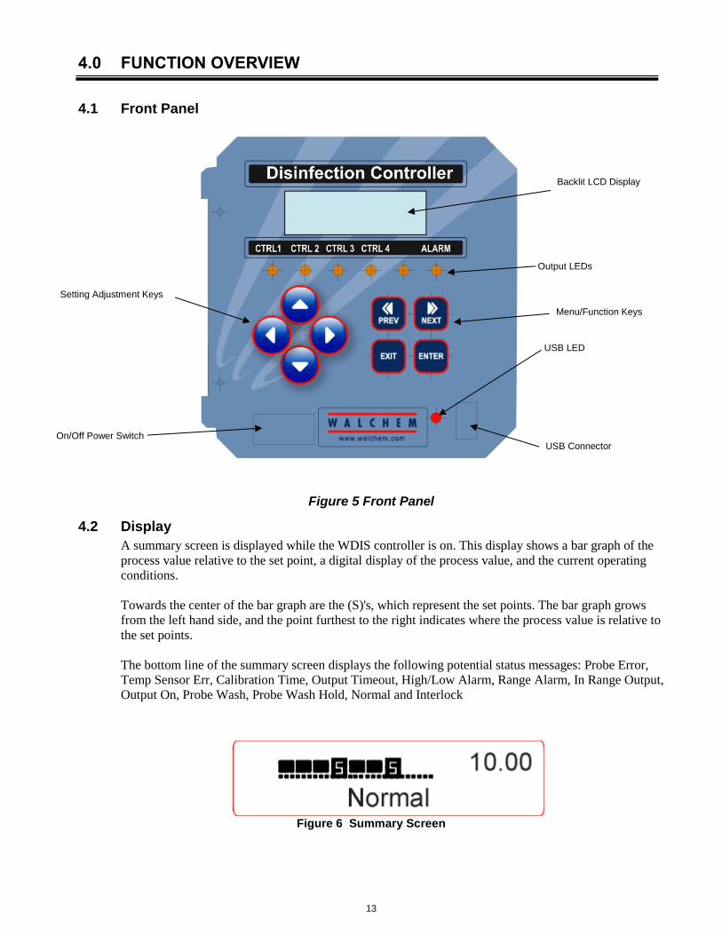
4.0 FUNCTION OVERVIEW
4.1 Front Panel
Figure 5 Front Panel
4.2 Display
A summary screen is displayed while the WDIS controller is on. This display shows a bar graph of the
process value relative to the set point, a digital display of the process value, and the current operating
conditions.
Towards the center of the bar graph are the (S)'s, which represent the set points. The bar graph grows
from the left hand side, and the point furthest to the right indicates where the process value is relative to
the set points.
The bottom line of the summary screen displays the following potential status messages: Probe Error,
Temp Sensor Err, Calibration Time, Output Timeout, High/Low Alarm, Range Alarm, In Range Output,
Output On, Probe Wash, Probe Wash Hold, Normal and Interlock
Figure 6 Summary Screen
On/Off Power Switch
Backlit LCD Display
Output LEDs
Setting Adjustment Keys
Menu/Function Keys
USB Connector
USB LED

14
4.3 Keypad
The keypad consists of 4 directional arrow keys and 4 function keys. The arrows are used to move the
adjustment cursor and change settings, while the function keys are used to enter values, and navigate the
various menu screens. The function keys are ENTER, EXIT, NEXT, and PREV (previous). NEXT and
PREV scroll through the various menu choices. ENTER is used to enter a submenu and to enter a
value. EXIT is used to back up one menu level. If you are at the main menu level, EXIT will return you
to the Summary Display.
To change a value in a submenu, the left/right arrow keys move the cursor left and right to each digit or
option that can be changed. The up/down arrows will change numeric values up or down, or scroll
through option choices. Press ENTER only when you have finished making all of the changes for that
menu screen.
4.4 Access Code
The WDIS series controller is shipped with the access code disabled. If you wish to enable it, see
Section 5.6 for operation. With the access code enabled, any user can view parameter settings, but not
change them. Note that this provides protection only against casual tampering. Use a lock on the cover
latch if you need more protection.
4.5 Startup
Initial Startup
After having mounted the enclosure and wired the unit, the controller is ready to be started.
Plug in the controller and turn on the power switch to supply power to the unit. The display will briefly
show the WDIS model number and then revert to the normal summary display. Scroll through the
menus and calibrate the sensor reading, and set the control parameters detailed in Section 5, Operation.
To return to the summary display, press the EXIT key until you return to this screen. The controller will
automatically return to this screen after 10 minutes.
Conditioning The sensor requires conditioning to acclimate the electrodes prior to generating stable readings.
Conditioning consists of installing the sensor in the flow cell, ensuring that the sensor remains wet at all
times and supplying power to the sensor.
The following conditioning times are recommended:
New Sensor: 12-24 hours
After membrane or electrolyte replacement: 1 hour
Normal Startup
Startup is a simple process once your set points are in memory. Simply check your supply of chemicals,
turn on the controller, calibrate it if necessary and it will start controlling.

15
4.6 Shut Down
To shut the WDIS controller down, simply turn off the power. Programming remains in memory.
The sensor must be stored with the measuring surfaces wet. If an extended shutdown will result in
the sensor dehydrating, it must be removed from its position in the process and stored in a clean, dry
place, without electrolyte in the cap. To reinstall, follow the directions in section 3.3.
5.0 OPERATION
These units control continuously while power is applied. Programming is accomplished via the local
keypad and display.
To view the top level menu, press any key. The menu structure is grouped by inputs and outputs. Each
input has its own menu for calibration and unit selection as needed. Each output has its own setup menu
including set points, timer values, direction of control, etc. as needed. After ten minutes of inactivity in
the menu, the display will return to the summary display. Keep in mind that even while browsing
through menus, the unit is still controlling.
5.1 Main Menu
The exact configuration of your WDIS controller determines which menus are available as you scroll
through the settings. Certain menus are only available if you purchase certain options. All settings are
grouped under the following main menu items.
Sensor
Control 1
Control 2
Control 3
Control 4
Time
4-20mA 1 Only if 4-20mA option installed
4-20 mA 2 Only if 2nd 4-20mA option installed
Access Code
Datalog Only if advanced USB feature is in model code
Config Only if advanced USB feature is in model code
Upgrade
The NEXT key travels forward through this list while the PREV key travels backwards through the list.
Pressing ENTER will Enter the lower level menu that is currently displayed.

16
Figure 7 Main Menu
Cl2
1.0
0pp
mS
enso
r
Cl2
1
.00
pp
mC
trl 1
A
11:4
0
Possib
le S
tatu
s S
cre
en
s
* P
rob
e E
rror
P
robe
Wa
sh
P
robe
Wa
sh H
old
* In
terl
ock
* O
utp
ut T
imeo
ut
* C
alib
ration
Tim
e
Ran
ge
Ala
rm
In
Ran
ge
Ou
tpu
t
Hig
h/L
ow
Ala
rm
Ou
tpu
t 1
On
O
utp
ut 2
On
O
utp
ut 3
On
O
utp
ut 4
On
N
orm
al
* T
hese
sta
tus s
cre
ens in
dic
ate
tha
t th
e d
iagno
stic a
larm
rela
y is a
ctivate
d.
Cl2
1.0
0p
pm
Ctr
l 2 A
11
:40
Cl2
1
.00
ppm
CT
RL 3
A
O
FF
Cl2
1.0
0p
pm
Tim
e T
hu
9
:12
Cl2
1.0
0p
pm
4-2
0 m
A_1
15
.66
mA
Cl2
1.0
0p
pm
CT
RL 4
A
OF
F
Pre
ss E
nte
r ke
y t
o e
nte
r m
enu o
r sub
menu
.
Pre
ss E
xit k
ey to e
xit m
enu
.
After
10 m
inu
tes o
f in
activity the
con
trolle
r w
ill
auto
ma
tically
retu
rn to th
e s
um
mary
scre
en.
Ope
ration
Legend
4-2
0m
A m
enu is o
nly
pre
sent if
4-2
0m
A o
ption
is insta
lled.
S1
.00
No
rmalS
Cl2
1
.00
pp
mA
ccess C
ode
DIS
Cl2
1.0
0pp
m4
-20 m
A_2
1
5.6
6 m
AC
l2
1.0
0p
pm
Da
talo
gC
l2
1
.00pp
mC
onfig
Cl2
1.0
0ppm
Upgra
de

17
5.2 Sensor Menu
The sensor menu provides the following settings: Calibration history (informational only), 1 point
calibration, zero calibration, sensor type selection, and other sensor setup menus. Each is discussed in
detail below. Refer to the Sensor Menu chart on the next page.
Note: If you are programming the unit for the first time you must set the Sensor Type first, selecting
between Chlorine (Cl2), Chlorine Dioxide (ClO2), Ozone, Peracetic Acid or Generic. See below.
Cal'd Displays the date of the last electrode calibration.
Calibration Press ENTER to perform a 1 point process calibration of the sensor.
With the sensor installed in the flow cell, and a sample circulating at the normal flow rate, and the
oxidizer concentration at the normal level, press ENTER at the Calibration screen. The display will show a ppm reading. If this does not match the known ppm as measured by a test kit or titration, use
the arrow keys to change the displayed value and press ENTER.
Cal Successful/Cal Failed
If the sensor response is good, then the display will read "Cal Successful". If the controller cannot
calculate an acceptable slope from that mV reading, it will read "Cal Failed". A failure usually means
that the sensor needs to be cleaned or replaced.
Zero Calibration This menu is used to calibrate the sensor to read precisely zero in pure water. It should be set at
installation with the sensor in air or pure water. This zero procedure should be repeated if a new
sensor is installed.
Press ENTER to start the zero adjust procedure. When asked “SnsrInPureWater?”, remove the sensor
from the flow cell and dry it off. Alternatively, supply the flow cell with a sample of water without
any oxidizer in it. Use the arrow key to change the “N” to “Y” and press ENTER. You will be asked
to press ENTER when the mV reading on the top line is stable. If the sensor offset was less than
±100 mV, the display will flash “SensorCalSuccess” and return to the Zero Calibration display. You
may now press EXIT.
If the message “BadZero: CalFail” appears, the offset was too large for the software to compensate. Check to see that the sensor is out of the bath and is dry and that all wiring connections are correct. If
none of these corrects the problem, install a new sensor.
Days Btwn Cal Use the arrow keys to set the number of days that you would like to go by before recalibrating the electrode. The controller will prompt you to recalibrate when that time has expired. Setting the number of
days to zero will disable this feature.
Sensor mV This menu displays the mV from the electrode. It is useful for troubleshooting.
Self Test Press ENTER to perform a self-test. If it says "FAIL" in the upper right hand corner, this indicates a
problem with the controller which should be returned for repair. If it passes, and you have a problem calibrating, it is an electrode or preamp problem.
Sensor Type Press ENTER to set up the controller to match the type of sensor to be used. Select Cl2, ClO2 or Ozone
if the sensor being used to detect those disinfectants has a range of 0 to 20 ppm. Select Peracetic Acid if
the sensor being used to detect Peracetic Acid has a range of 0 to 2000 ppm. For any other disinfectants or ranges, select Generic and then program the slope and offset of that sensor in the next menus. Use the Up
and Down arrows to toggle between Cl2 (chlorine), ClO2 (chlorine dioxide), Ozone, Peracetic Acid and
Generic, then press ENTER to make your selection. The controller will warn you to check your set
points because the acceptable range of set points may have changed.
Press any key to clear the warning message.
Slope Only appears if the Sensor Type is Generic.
Press Enter to change the slope.
Use the arrow keys to set the nominal slope of the sensor you are using. The number may be negative.
When performing a 1-point calibration later, the controller will allow a slope of 0.2 to 10 times of the
nominal slope.
Offset Only appears if the Sensor Type is Generic.
Press Enter to change the offset.
Use the arrow keys to set the nominal offset of the sensor you are using. The number may be negative.
When performing a zero calibration later, the controller will allow an offset of 100 mV of the nominal
offset.

18
Figure 8 Sensor Menu
. .
. .
WA
RN
ING
. . .
.C
heck S
et P
oin
ts
Sen
sor
Cal'd
M
ar/
10/9
61.0
0 p
pm
Sen
sor
1 P
t C
alib
ratio
n1
.00 p
pm
Se
nsor
Ze
ro C
al
1.0
0 p
pm
Zero
Re
adn -
5.0
mV
Ente
r w
he
n S
tab
le
Sen
sor
Days B
twn
Ca
l 7
1.0
0 p
pm
Sen
sor
Type
Cl2
Cl2
Sen
sor
Typ
e
Cl2
ClO
2
Sen
sor
Typ
e
Cl2
Ozon
e
Bu
ffer
Set
D
IND
IN 6.7
5, 9
.23 .
.
Se
nso
r
Se
nso
r Type
Cl2
1.0
0 p
pm
1.0
0 p
pm
Se
nso
r
Pre
ss E
nte
r key to
ente
r m
enu.
Pre
ss E
xit k
ey to e
xit m
enu.
Blin
kin
g fie
lds m
ay b
e e
dited
with t
he a
dju
st arr
ow
s.
Pre
ss E
nte
r w
he
n m
odific
ation is c
om
ple
te to r
etu
rn
to M
ain
Menu
Le
vel.
Op
era
tio
n
Sen
sor
Sen
sor
mV
-1
00
mV
1.0
0 p
pm
Se
nsor
Se
lf T
est
1
.00 p
pm
Self T
est
P
ass
S113
0 m
V T
13
68m
V1
Pt C
aib
ration
ppm
1.0
0
Sen
sor
Typ
e
Cl2
Pera
cetic A
cid
Sen
sor
Typ
e
G
EN
Ge
ne
ric
Buffe
r S
et D
IND
IN 6
.75,
9.2
3
. .
Senso
r
S
lop
e
-
100
1.0
0 p
pm
Slo
pe
mV
/ p
pm
-1
00
Buffer
Set
D
IND
IN
6.7
5, 9
.23
.
.
Sensor
O
ffset 0
1.0
0 p
pm
Offse
tm
V
0
11
1Legend
On
ly a
pp
ea
rs if
se
nsor
typ
e is
Ge
neri
c.

19
5.3 Control 1 - 4 Menus
The Control 1 - 4 menus are separate from each other but operate in exactly the same way. Each menu
provides the following independent settings: Set Point, Dead Band, Time Limit, Interlock, Output
Mode, Assign Input, HOA, Set Point, Dead Band, and Time Limit. The Control menu will be indicated
on the display by one of the following: (The 'A' indicates that the output is being controlled
automatically.)
NOTE: When programming the unit for the first time, go to the “Mode” menu to select how that
output will operate. Making this assignment first will bring up the correct menus for the Mode you
are using.
Ctrl 1 A OFF Indicates that the output is currently OFF.
Ctrl 1 A 10:00 Indicates the length of time that the output has been ON.
Ctrl 1 A Intrlck Indicates that control has been suspended because the Interlock switch is Open
Ctrl 1 A TIMEOUT Indicates that the output has been on longer than the Time Limit.
Mode Press the ENTER key to change the mode in which the output will operate. The relays may be a low set point, a
high set point, a low alarm, a high alarm, an out-of-range alarm, an in-range output, or a probe wash. Use the arrow keys to scroll through the choices.
Low Set Point Press ENTER when this is displayed to select a low set point. The relay will close when the process value goes
below the set point value. The summary screen will display that the output is on. A time limit menu will be
available, to prevent runaway control. An Interlock menu will be available to allow you to stop control if flow past the sensor stops.
High Set Point
Press ENTER when this is displayed to select a high set point. The relay will close when the process value goes
above the set point value. The summary screen will display that the output is on. A time limit menu will be available, to prevent runaway control. An Interlock menu will be available to allow you to stop control if flow
past the sensor stops.
Low Alarm
Press ENTER when this is displayed to select a low alarm. The relay will close when the process value goes
below the set point value. The summary screen will display “Low Alarm”. No time limit or interlock features
will be available.
High Alarm
Press ENTER when this is displayed to select a high alarm. The relay will close when the process value goes
above the set point value. The summary screen will display “High Alarm”. No time limit or interlock features
will be available.
Out Range Alarm
Press ENTER when this is displayed to select an out-of-range alarm. The relay will close when the process value is either above or below the two set point values. The summary screen will display “Range Alarm”. No
time limit or interlock features will be available.
In Range Output
Press ENTER when this is displayed to select an in-range output. The relay will close when the process value is
between the two set point values. The summary screen will display “In Range Output”. No time limit or
interlock features will be available.
Time Prop Hi
Press ENTER when this is displayed to use time proportional control with a high set point. In Time Proportional
Mode, the farther away from the set point the system is, the longer the ON time. Refer to the drawings below for
an illustration of Time Proportional Mode.

20
Mode
(continued)
Time Prop Lo
Press ENTER when this is displayed to use time proportional control with a low set point. In Time Proportional Mode, the farther away from the set point the system is, the longer the ON time. Refer to the drawings below for
an illustration of Time Proportional Mode.
Probe Wash
Press ENTER when this is displayed if you want to use the relay to interrupt control and activate a pump or
valve to wash down the electrode. The summary screen will display “Probe Wash”.
Low Set Point Only appears if the Mode is Low Set Point
Press ENTER if you want the Control relay to close if the process goes below a certain value. The status screen
message will be Output ON. This denotes a normal correction of the process value. If you want the status
message to be Low Alarm, indicating a problem, choose an Output Mode of Low Alarm as described below.
High Set Point
Only appears if the Mode is High Set Point
Press ENTER if you want the Control relay to close if the process above a certain value. The status screen
message will be Output ON. This denotes a normal correction of the process value. If you want the status
message to be High Alarm, indicating a problem, choose an Output Mode of High Alarm as described below.
Low Alarm Only appears if the Mode is Low Alarm, In Range or Out of Range
Press ENTER if you want the Control relay to close if the process goes below a certain value. The status screen
message will be Output ON. This denotes a normal correction of the process value. If you want the status
message to be Low Alarm, indicating a problem, choose an Output Mode of Low Alarm as described below.
High Alarm Only appears if the Mode is High Alarm, In Range or Out of Range
Press ENTER if you want the Control relay to close if the process above a certain value. The status screen
message will be Output ON. This denotes a normal correction of the process value. If you want the status
message to be High Alarm, indicating a problem, choose an Output Mode of High Alarm as described below.
Dead Band Use the arrow keys to set the desired dead band, then press ENTER. If the set point is 7.00 ppm, and the dead
band is 0.05 ppm, then the relay will close at 7.00 ppm and open 0.05 ppm away from 7.00.
DEAD BAND
LOW SET POINT
ppm
TIME
Pump Off
Pump On
Pump Off
LOW SET POINT
ppm
TIME
ZERO DEADBAND: NOT RECOMMENDED
Pump On & Off rapidly, damaging relay
21
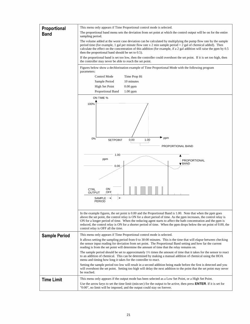
Proportional Band
This menu only appears if Time Proportional control mode is selected.
The proportional band menu sets the deviation from set point at which the control output will be on for the entire sampling period.
The volume added at the worst case deviation can be calculated by multiplying the pump flow rate by the sample
period time (for example, 1 gal per minute flow rate x 2 min sample period = 2 gal of chemical added). Then calculate the effect on the concentration of this addition (for example, if a 2 gal addition will raise the ppm by 0.5
then the proportional band should be set to 0.5).
If the proportional band is set too low, then the controller could overshoot the set point. If it is set too high, then the controller may never be able to reach the set point.
Figures below show a dechlorination example of Time Proportional Mode with the following program
parameters:
Control Mode Time Prop Hi
Sample Period 10 minutes
High Set Point 0.00 ppm
Proportional Band 1.00 ppm
In the example figures, the set point is 0.00 and the Proportional Band is 1.00. Note that when the ppm goes
above the set point, the control relay is ON for a short period of time. As the ppm increases, the control relay is ON for a longer period of time. When the reducing agent starts to affect the bath concentration and the ppm is
reduced, the control relay is ON for a shorter period of time. When the ppm drops below the set point of 0.00, the
control relay is OFF all the time.
Sample Period This menu only appears if Time Proportional control mode is selected.
It allows setting the sampling period from 0 to 30:00 minutes. This is the time that will elapse between checking
the sensor input reading for deviation from set point. The Proportional Band setting and how far the current reading is from the set point will determine the amount of time that the relay remains on.
The sample period should be set to approximately 1½ times the amount of time that it takes for the sensor to react
to an addition of chemical. This can be determined by making a manual addition of chemical using the HOA menu and timing how long it takes for the controller to react.
Setting the sample period too low will result in a second addition being made before the first is detected and you
will overshoot the set point. Setting too high will delay the next addition to the point that the set point may never be reached.
Time Limit This menu only appears if the output mode has been selected as a Low Set Point, or a High Set Point.
Use the arrow keys to set the time limit (min:sec) for the output to be active, then press ENTER. If it is set for
"0:00", no limit will be imposed, and the output could stay on forever.
ppm
ON TIME %
100%
0% SETPOINT
PROPORTIONAL BAND
Figure 12a Time Proportional Mode Setup
SAMPLE PERIOD
CTRL OUTPUT
ON OFF
ppm
0.00
1.00
PROPORTIONAL BAND
Figure 12b Time Proportional Mode Timing Illustration
0.00 1.00

22
Reset Timer This menu only appears if the output mode has been selected as a Low Set Point, or a High Set Point and the time
limit has expired.
Determine the reason that the output stayed on too long, and once the problem has been solved, press ENTER to
reset the timer.
Probe Wash Sched
This menu only appears if the output mode has been selected as a Probe Wash.
Press ENTER to program the probe wash schedule. The display will be “Event A 00:00 00”. The first numbers
are the time of day, in military time, when the probe wash will take place. The last two numbers are the time, in seconds, that the relay will be closed and the pump or valve attached to the relay will clean the probe. Use the
arrow keys to change the time of day and the duration of the cleaning. When both values are set, press ENTER.
If the electrode needs to be washed more than once a day, additional events may be accessed by pressing the
NEXT key. Once all events are programmed, press EXIT to return to the top level menus.
Hold Time This menu only appears if the output mode has been selected as a Probe Wash.
Use the arrow keys to select the time delay in seconds between the probe wash ending and control beginning again. The hold time can be a maximum of 99 seconds. During the hold time, the summary display will indicate
“Probe Wash Hold”.
Interlock Use the Up and Down arrows to toggle between Y(Yes) and N(No). Choosing Y means that the output will deactivate if the device attached to the controller is open. For example, if the electrode is installed in a
recirculating pipe line, a flow switch that is closed if flow is sufficient and open if flow is insufficient may be
installed in the line, so that if flow past the electrode stops, the controller will not pump in chemicals based on a
stagnant sample. Similarly, a level switch may be attached to prevent control of an empty batch tank.
HOA Use the Left and Right arrows to move between Hand, Off and Auto. In Hand (Manual) mode, the output will be
turned on immediately for a maximum of 10 minutes. In the Off mode, the output will be turned off indefinitely. In the Auto mode, the output turns on and off in response to changes in the process value relative to the set point.
The letter inside the block on the status screen indicates which mode the output is in.

23
Figure 9 Control 1 - 4 Menu
Cl2 1.00 ppmCtrl 1 1:01:15A
Ctrl 1 OFFLo Alarm 2.00
A
Ctrl 1 1:01:15Mode LowSetPoint
A
Ctrl 1 1:01:15Dead Band 0.10
A
Ctrl 1 1:01:15Interlock N
ACtrl 1 1:01:15Time Limit 0:00
A
Ctrl 1 OFF
Ctrl 1 Intrlck
Ctrl 1 TIMEOUT
Possible status screens
Press Enter key to enter menu.
Press Exit key to exit menu.
Blinking fields may be edited with the adjust arrows.
Press Enter when modification is complete to return
to Main Menu Level.
Operation
Ctrl 1 OFFLo Set Pt 2.00
A Ctrl 1 OFFHi Set Pt 12.00
A
Ctrl 1 1:01:15Reset Timer Y
A Ctrl 1 1:01:15HAND OFF >AUTO
A Ctrl 1 OFFHold Time 1:00
A
Mode LowSetPointLowSetPoint
Mode LowSetPointHi Set Point
Mode LowSetPointLowAlarm
Mode LowSetPointHighAlarm
Mode LowSetPointOutRangeAlm
Mode LowSetPointInRangeOutp
Mode LowSetPointProbeWash
Ctrl 1 1:01:15
Ctrl 1 PW
A
A
A
A
A
Probe Wash SchedEvent A 12:00 99
Ctrl 1 OFFProbe Wash Sched
A
Probe Wash SchedEvent J 12:00 99
Ctrl 1 OFFHi ALarm 12.00
A
Ctrl 1 80% OnA
1 1
1
4 4
3 2 2
2
Ctrl 1 1:01:15Prop Band 1:00
A Ctrl 1 1:01:15Smple Period 10:00
A
5 5
LegendMenu choices that appear only when Hi Set Point or
Lo Set Point mode is selected. Set points appear as
needed depending on output mode (i.e. the Low Set
Point does not appearif Hi Set Point mode is selected).
Neither set point appears if the Probe Wash mode is
selected.
Menu choices that appear when Probe Wash mode
is selected.
Appears only if limit timer has expired.
Menus appear only if Hi or Lo Alarm mode or
Out of Range or In Range Output is selected.
If Hi Alarm mode is selected, only Hi Alarm
appears, etc. Both appear if In Range output
or Out of Range Alarm is selected.
Menus appear only when Time Proportional
Mode is selected.
1
4
3
2
5
Mode LowSetPointTime Prop Hi
Mode LowSetPointTime Prop Lo

24
5.4 4-20 mA 1 and 2 Menus (Optional)
These menus will only appear if the optional 4-20 mA output board(s) is installed. They are used to set
the scale of the 4-20 mA output. It contains the following menu selections: Set 4 mA Point, Set 20 mA
Point, and Calibrate.
4 mA Pt Use the arrow keys to enter the process value in ppm that you want to correspond to a 4 mA output from the
controller.
20 mA Pt Use the arrow keys to enter the process value in ppm that you want to correspond to a 20 mA output from the controller.
Calibrate This menu is used to calibrate instruments connected to the mA output. The 4-20 mA output is extremely
accurate and stable and therefore will never need calibration. This feature allows other devices to be calibrated at the 4 and 20 mA points. Press ENTER to start the calibration.
Fixed 4 mA Out The controller will output 4.00 mA. Adjust the chart recorder or data logger per its instruction so that the process value displayed is what is expected for a 4.00 mA input.
Fixed 20 mA Out As above, except that the controller will output 20.00 mA.
The design of the 4-20 mA output is such that it should never need calibration. If the mA signal is not what it should be, call the factory for service.
Figure 10 4-20 mA 1 and 2 Menus
Cl2 1.00ppm4-20mA 12.4mA
4-20mA_1 12.4mASet 4mA Pt 0
4-20mA_1 12.4mACalibrate 4-20mA
4-20mA Menu
4-20mA menu is only present if4-20mA hardware is installed.
Calibrate 4-20mAFixed 4mA Output
Calibrate 4-20mAFixed 20mA Output
4-20mA_1 12.4mASet 20mA Pt 0

25
5.5 Time Menu
The time menu is used to set the date and time that the controller uses to schedule probe washing and
calibration prompts. There is only one menu selection: Set Clock.
Set Time Press ENTER to set the clock. Use the arrow keys to change the year, date, and month, then press ENTER.
Use the arrow keys again to set the day of the week and the time. Use military time (for example, 1:00 PM is
13:00). Press ENTER to return to the top level clock menu.
Figure 11 Time Menu
Cl2 1.00 ppmTime Sat 12:15
Time Sat 12:15Set Clock
Set ClockSet Jan/ 3/98
Set ClockSet Thu 12:15

26
5.6 Access Code Menu
This menu determines whether the access code feature of the controller is enabled or disabled and
allows you to customize the access code to your own value. The access code controls whether or not
you are allowed to change the parameters in the controller. With the access code disabled, any user may
change any parameter. With the access code enabled, any user can view any parameter, but cannot
change them. Once an attempt is made to change a parameter, the display will prompt the user to enter
the access code. If the correct access code is entered, the parameters can be changed. If the wrong
access code is entered the parameters cannot be changed. Once the access code has been correctly
entered, it will remain valid until there is a period of 10 minutes without a key being pressed.
The access code menu will appear as shown below:
Access Code DIS Indicates that the access code is disabled. No access code is required to change any setting.
Access Code REQ Indicates that the access code is required to alter settings.
Access Code OK Indicates that the access code is required and has been entered correctly.
Enable N / Y Press the Up or Down arrow key to change the N to Y and press ENTER to enable the access code
feature. If the access code is enabled you must first enter the access code to disable it.
New Value Press ENTER to display the current access code value and use the arrow keys to change it to any value between 0 and 9999. If the access code has been enabled, you will be prompted to enter the current
access code before being allowed to change it. You must remember the access code if you enable it.
The Factory default Access code is 1995.
If you change the access code and can't remember it follow this procedure:
1. Turn off power to the controller. 2. Wait 10 seconds.
3. Press and Hold the UP and DOWN arrow keys while turning on the power.
4. Read the access code on the display. 5. Release the keys, and the access code will disappear.
Figure 12 Access Code Menu
Cl2 1.00ppmAccess Code DIS
Any Top DisplayAccess Code 0000
Access Code DISEnable N
Access Code DISEnable Y
Access Code DISNew Access Code 0
Access Code DISValue 1234
Access Code REQ
Access Code OK
Access Code Menu
Possible status screens
The Access Code prompt may appear at any screen in the entire menustructure if the current access code has not been entered by the user.Access code entries will be valid for 10 minutes from the most recent key press.
Enter any four digit code

27
5.7 Datalog Menu
This menu is available if the data logging option has been purchased. This is indicated in the model
code by the letter U at the end of the model code. This menu allows you to save data from the controller
to a USB flash drive.
The controller has four logs, the Current Datalog, the Backup Datalog, the Event Log, and the Reset
Log. All files are in a CSV format that may be opened in a spreadsheet such as Microsoft Excel.
Current Datalog Contains the following data taken at 10 minute intervals:
Disinfectant ppm
When the current datalog is downloaded to a USB stick, it is erased and a new
log file is started.
If the current datalog is not downloaded before it reaches its maximum size (at
least 60 days of data) the oldest data is overwritten by the newest data.
Backup Datalog Contains the same data as the current log but it is never erased. When the backup
log reaches its maximum size (at least 60 days of data), the oldest data is
overwritten by the newest data.
Event Log Contains columns for each relay and flow switch input, as well as the date and
time. Each time any of these change state, the date and time is updated and it will
show a 1 if the relay is on and 0 if it is off, and a 1 if the flow switch indicates no
flow, 0 if there is flow. Tens of thousands of events will be recorded before the
oldest data is overwritten by the newest, the number varying with the controller’s
configuration.
Reset Log Consists of time stamps of when power was lost, when it was returned, and the
cause of the reset.
Current or Backup Datalog
Place a USB flash drive with at least 10 MB capacity into the USB port on the front panel of the controller. Press the Enter key to download the file from the controller to the disk.
The file name for the Current Datalog will be Datalog<serial number><date><time>.csv
using the date and time it was downloaded. The file name for the Backup Datalog will be Datalog<serial number><date><time> .csv using the date and time it was created.
The controller will display the progress of the file download process. If the file was successfully copied to the USB disk the controller will display Transfer Success.
Copy Event Log Place a USB flash drive with at least 10 MB capacity into the USB port on the front panel
of the controller. Press the Enter key to download the file from the controller to the stick.
The file name will be Eventlog<serial number><date><time>.csv.
The controller will display the progress of the file download process. If the file was
successfully copied to the USB disk the controller will display Transfer Success, otherwise
Transfer Fail 1.
Transfer Success Transfer Fail 1
Copy Reset Log
Place a USB flash drive with at least 10 MB capacity into the USB port on the front panel
of the controller. Press the Enter key to download the file from the controller to the stick.
The file name will be Resetlog<serial number><date><time>.csv.
The controller will display the progress of the file download process. If the file was
successfully copied to the USB disk the controller will display Transfer Success.
Transfer Success Transfer Fail 1

28
Figure 13 Datalog Menu
DatalogCurrent Datalog
DatalogCopy Event Log
Datalog
Cl2 1.00 ppm
DatalogTransfer Success
Next
Prev
DatalogCopy Reset Log
Next
Prev
DatalogTransfer Success
DatalogTransfer Success
Possible Status Screens
Transfer Success
Transfer Fail 1
DatalogBackup DataLog
Next
Prev
DatalogTransfer Success

29
5.8 Config Menu
This menu allows you to export a file that contains all of the set points in the controller to a USB flash
disk drive, and then later import the set points into another controller.
Export Config Place a USB flash drive with at least 10 MB capacity into the USB port on the front panel of the
controller. Press the Enter key to export the configuration file from the controller to the stick. The file
name will be UCF.ini. If you are exporting files with different set points you may rename the file to something that describes it, as long as it has an ini extension.
The controller will display the progress of the file download process. If the file was successfully
exported to the USB disk the controller will display Transfer Success, otherwise Transfer Fail 1.
Transfer Success Transfer Fail 1
Import Config Place a USB flash drive that contains only one configuration file stored on the root directory of the
stick into the USB port on the front panel of the controller. Press the Enter key to import the
configuration file from the stick to the controller. The file name must have an ini extension in its name.
The controller will display the progress of the file import process. If the file was successfully imported
from the USB disk the controller will display one of the messages below:
Import Failure Indicates that there were problems connecting to or accessing the USB
stick.
Import Success: Any key to reboot
The configuration file import succeeded and will be ready for use after reboot.
File Open Failed A config file could not be found on the USB stick or the USB stick file
system could not be accessed.
File Read Failed The config file is too short (incomplete) or empty.
Invalid CFG File The imported file is not a valid config file.
Invalid Model The imported config file is not for this controller model.
Wrong SW Version The version of the imported config file is not compatible with this
controller software version.
Corrupt CFG File The imported config file is corrupt. (The checksum failed.)
Wrong file Size The size of the imported config file is wrong.
ConfigExport Config
ConfigImport Config
1.00 ppm
Config
Cl2
ConfigTransfer Success
ConfigENTR selects cfg
Next
Prev
ConfigImport SuccessAny Key to Reboot
ENTR selects cfgUCF.ini
ENTER EXIT ENTER EXIT
ENTER EXIT
ENTER EXIT
Possible Status Screens
Transfer Success
Transfer Fail 1 Possible Status Screens
Import Failure
Import SuccessAny Key to Reboot
File Open Failed
File Read Failed
Invalid CFG File
Invalid Model
Wrong SW version
Corrupt CFG File
Wrong File Size
Figure 14 Config Menu

30
5.9 Upgrade Menu
This menu is used to upgrade the software to a newer version. If a new version of the software is
available, an upgrade file will be posted on our web site. Save this file to a USB flash disk drive. It
needs to be the only upgrade file stored on the root directory of the stick. Press the Enter key to import
the software upgrade file from the stick to the controller.
The controller will display the progress of the file import process. If the file was successfully imported
from the USB disk the controller will display Transfer Success. The controller will automatically reboot
and come up with the new software installed.
Upgrade The controller will display the progress of the file import process. If the file was successfully imported from the USB disk the controller will display Transfer Success. The controller will automatically
reboot and come up with the new software installed.
If the software upgrade fails, you will see one of the following messages:
UpgradFileInvald The file found on the USB stick is for the wrong product, or is corrupt. Try getting the correct upgrade file and make sure it’s the only upgrade
file on the stick.
No Upgrade File There is no upgrade file stored on the stick, or the file is named incorrectly.
CorrptUpgradFile Try getting a new copy of the file.
Flash Failure The flash memory on the processor board has a problem. Repair or
replace the front panel assembly.
To check that it was successful, turn off power to the controller, then press the Enter key while turning
power on. The controller will show the software version, which should match the name of the upgrade
file that you used.
Figure 15 Upgrade Menu
UpgradeStart Upgrade
1.00 ppm
Upgrade
Cl2
UpgradeTransfer Success
Possible Status Screens
Transfer Success
UpgradFileInvald
No Upgrade File
CorrptUpgradFile
Flash Failure

31
6.0 Maintenance
The WDIS control module itself needs very little maintenance. Clean the outside of the controller
enclosure with a damp cloth. Do not spray down the controller unless the enclosure door is closed and
latched. "Pigtails" should be protected from spray or wash-down. Check the cords and cables for
damage.
6.1 Sensor Maintenance
Cleaning the Membrane
Instructions for cleaning the membrane vary depending upon the type of contamination. Follow the
directions for replacing the membrane shown below, replacing step 3 with one of these cleaning
methods:
For general deposits:
Rinse in clear cold water.
For calcium scale:
Soak in dilute (1% by volume) hydrochloric acid, then rinse in clear cold water.
For oils:
Rinse in isopropyl alcohol.
DO NOT use cleaners or detergents containing surfactants, as these will reduce the life of the
membrane.
If the sensor still cannot be calibrated after cleaning, replace the membrane cap as described below.
Replacing the Membrane
CAUTION: Wear gloves and safety glasses during assembly of the sensor since the electrolyte is a
STRONG ACID. It is recommended to perform this operation over a sink with running water available.
After using, re-cap any remaining electrolyte until the next use.
1. Hold the sensor vertically with the membrane facing down and carefully unscrew the membrane cap.
Always move the gray bands to uncover the vent hole before removing the cap!
2. Rinse the electrolyte fill solution off the cap and electrodes with cold water.
3. Discard the old membrane cap.
4. Unpack the new membrane cap, taking care not to touch the membrane or get it dirty.
5. Fill the membrane cap to the top with the electrolyte fill solution.
6. Hold the sensor body vertically with the tip pointing down and SLOWLY screw on the membrane cap
until it is hand tight. Be prepared for some electrolyte solution to squeeze out from the cap
7. Rinse your hands, the sensor, and all surfaces contaminated with electrolyte solution with running
water.
8. Check the sensor for leaks, especially at the membrane and the membrane cap threads. If any leaks are
detected, tighten the membrane cap or replace it.

32
6.2 Replacing the Fuses
CAUTION: Disconnect power to the controller before opening front panel!
Locate the fuses on the circuit board at the back of the controller enclosure. (See figure 4.) Gently
remove the old fuse from its retaining clip and discard. Press the new fuse into the clip, secure the front
panel of the controller and return power to the unit.
Warning: Use of non-approved fuses can affect product safety approvals. Fuse ratings depend on
controller power rating. Specifications are shown below. To insure product safety certifications are
maintained, it is recommended that a Walchem fuse be used.
F1 Fuse Walchem P/N F2 Fuse Walchem P/N
5 x 20 mm, 1.0A, 250V 103163 5 x 20 mm, 6A, 250V 102834
7.0 TROUBLESHOOTING
CAUTION: Disconnect power to the controller before opening front panel!
Troubleshooting and repair of a malfunctioning controller should only be attempted by qualified
personnel using caution to ensure safety and limit unnecessary further damage. Contact the factory.
7.1 Error Messages
Cal Failed The expected response (Nominal Slope) is –100 mV/ppm for Cl2, ClO2, and Ozone, or –1 mV/ppm for Peracetic Acid, or the
setting used in the Slope menu for Generic. The acceptable range is for the slope to equal 0.2 to 10 times the nominal slope. If the
sensor response is outside the acceptable range, refer the sensor’s instruction manual for troubleshooting.
Sens Low No Cal The Calibrate menu will not allow a calibration if the concentration is too close to zero ppm. If the sensor input is above –5 mV
(approximately 0.05 ppm), this message will appear. If the actual concentration is actually higher, refer to the sensor’s instruction
manual for troubleshooting.
Probe Error No Cal The Calibration menus will reject the calibration if the sensor is in a Probe Error condition. Refer to the troubleshooting for Probe
Error below.
Bad Zero Cal Fail The Zero Calibration will fail if the mV reading from the sensor is outside of the range –100 to 100 mV. If the actual concentration
is actually zero, refer to the sensor’s instruction manual for troubleshooting.

33
Output Timeout This error message appears if one of the control outputs has been on longer than the maximum amount of time programmed in the
"Time Limit" menu found in the Control 1-4 menus. It is reset by answering "Yes" to the "Reset Timer" prompt that will appear.
There are a number of possible reasons that the output could go on for longer than normal:
Possible Causes Corrective Action The process went further out of control than normal. Increase time limit or reset timer.
The chemical supply has run out. Replenish the chemical supply.
The pump or valve or supply line is faulty. Repair or replace the control device.
Wrong chemical is being controlled. Replace with correct chemical.
The sensor is not responding to changes. Repair or replace sensor or cable.
Refer to sensor instructions.
Evaluate mixing or recirculation.
High Alarm This error message appears if the ppm reading exceeds the set point for one of the Control outputs that has been configured as a
high alarm output. There are a number of possible causes for this condition:
Possible Cause Corrective Action
The process went further out of control than normal. May have to increase chemical flow rate.
The chemical supply has run out. Replenish the chemical supply.
The pump or valve or supply line is faulty. Repair or replace the control device.
Wrong chemical is being controlled. Replace with correct chemical.
The sensor is not responding to changes. Replace sensor or cable. Evaluate mixing or recirculation.
The pump is siphoning, valve leaking. Repair or replace the control device or re-route tubing.
Control output has been left in "HAND" mode. Switch back to "AUTO".
It may be a normal part of the process. None required.
Probe Error This error message appears if the sensor input signal is outside of the normal range. This usually indicates that the sensor has been
disconnected or is faulty. It could appear under normal conditions if the ppm is outside of the operating range of 0-20 (or 2000 if
Peracetic acid).
Possible Cause Corrective Action
Controller is faulty; fails self test (see section 5.2) Re-check self test with sensor disconnected. If it still fails,
send controller back for repair. If it passes, sensor is faulty. Sensor has no power to it. If battery powered preamp, replace battery. If preamp is
powered by our controller, check +5V, -5V terminals vs COM
terminal. Should read +5VDC ±5% and -4.6 VDC ±-5%.
Sensor is faulty. Indicated if ±5VDC power out of spec w/sensor attached, but
in spec without sensor attached. Replace sensor.
Sensor is faulty.
Replace sensor.
Interlock
This error message indicates that control has been stopped because the closed contact signal from a flow switch or level switch is
now open and one or more control outputs have been programmed to interlock.
Possible Cause Corrective Action
Flow has stopped, level too low. May be a normal condition, otherwise restore flow or level.
Flow, level switch disconnected. Reconnect.
Flow, level switch faulty. Verify that switch closes using an ohmmeter. If not, repair or
replace. Controller faulty. Verify that error message disappears if controller flow switch
input is shorted. If not, repair controller.
34
Calibration Time This message appears to prompt you to perform the routine maintenance of cleaning and calibrating the sensor. It does not appear
based upon any analysis of the condition of the sensor. The frequency of calibration is set by the user in the "Days Between Cal"
menu found in the "Sensor" menu. If you do not want to be prompted to perform a calibration, set this menu to "0".
Low Alarm As above for "High Alarm", except that the reading is below the set point of one of the Control outputs that has been set up as a
low alarm output. Refer to the possible causes and corrective actions listed above for the "High Alarm" error message.
Out Range Alarm This error message appears if the ppm reading is outside of the range selected for one of the Control outputs that has been
programmed as an "Out of Range Alarm". Refer to the possible causes and corrective actions listed above for the "High Alarm"
error message.
In Range Output
This error message appears if the ppm reading is inside of the range selected for one of the Control outputs that has been
programmed as an "In Range Alarm". Refer to the possible causes and corrective actions listed above for the "High Alarm" error
message.
Check Set Points This is a normal display if you have changed the choice of sensor type in the Sensor menu. The default set points for each choice
could be different, and will not match what you need for your application. Always select the sensor type before setting the control
output set points.
8.0 SERVICE POLICY
The WDIS Series Disinfection Controller has a 2-year warranty on electronic components and a 1-year
warranty on mechanical parts (keypad, terminal strip and relays).
We stock circuit boards for immediate exchange after we have isolated the cause of the problem.
Factory authorized repairs that are received by next-day-air will be returned within 24 hours. Normal
priority for returns is two weeks.
Out of warranty repairs or circuit board exchanges are done on a flat fee basis after the warranty is
expired.

FIVE BOYNTON ROAD HOPPING BROOK PARK HOLLISTON, MA 01746 USA TEL: 508-429-1110 FAX: 508-429-7433 Web: www.walchem.com