Embed Size (px)
Citation preview
Surface Finishing Machines
we redefine
VibratoryFinishing
180
9080
100
70110
60
120
50
130
40
140
30
150
20160
10170
1360
120
7011
0
80
100
0180
9080
100
70110
60
120
50
130
40
140
30
150
20160
10170
1360
120
7011
0
80
100
0180
9080
100
70110
60
120
50
130
40
140
30
150
20160
10170
1360
120
7011
0
80
100
0180
9080
100
70110
60
120
50
130
40
140
30
150
20160
10170
1360
120
7011
0
80
100
0180
9080
100
70110
60
120
50
130
40
140
30
150
20160
10170
1360
120
7011
0
80
100
0
2
Introduction
2
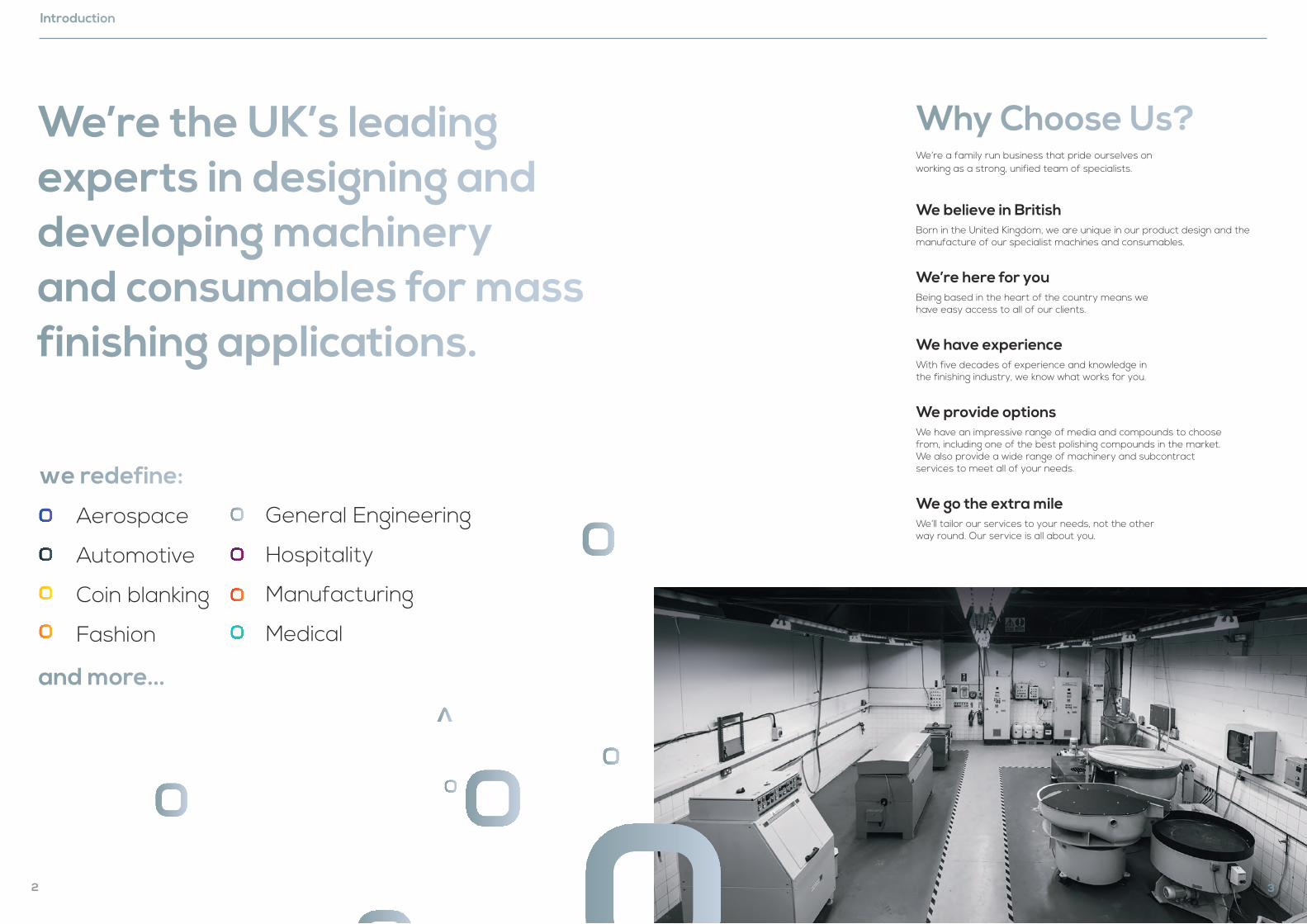
We’re the UK’s leading experts in designing and developing machinery and consumables for mass finishing applications.
we redefine:
Aerospace
Automotive
Coin blanking
Fashion
General Engineering
Hospitality
Manufacturing
Medical
and more...
3
Why Choose Us? We’re a family run business that pride ourselves on working as a strong, unified team of specialists.
We believe in BritishBorn in the United Kingdom, we are unique in our product design and the manufacture of our specialist machines and consumables.
We’re here for youBeing based in the heart of the country means we have easy access to all of our clients.
We have experienceWith five decades of experience and knowledge in the finishing industry, we know what works for you.
We provide optionsWe have an impressive range of media and compounds to choose from, including one of the best polishing compounds in the market. We also provide a wide range of machinery and subcontract services to meet all of your needs.
We go the extra mileWe’ll tailor our services to your needs, not the other way round. Our service is all about you.
Mass Finishing
4
Forging Drawing Tolerance
Super Finish Tolerance
ActOn Target Performance
high stock removal
deburring
descaling
removal of machining lines
removal of surface defects
radius formation
super-finishing
The processes can be configured as a batch system or a continuous system. Parts that are processed using a batch system
will be loaded into the machine, processed and unloaded before the next batch is ready. This continuous system is a process
where the parts are loaded at one end, and come out at the other end in the finished condition.
By combining our complete process knowledge with decades of experience, and our all-encompassing range of machinery,
we can deliver the most optimum, cost-effective and environmentally friendly finishing solution for your needs.
The aim of this process can vary based on
the type of application, which include:
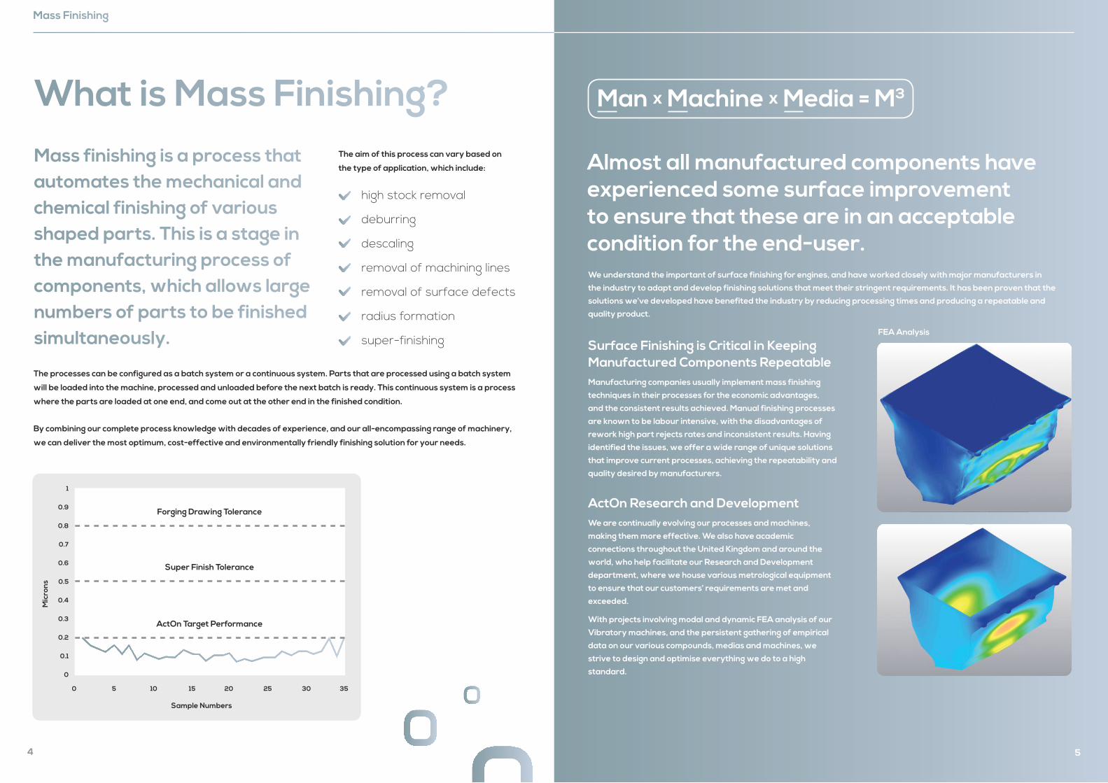
What is Mass Finishing? Mass finishing is a process that automates the mechanical and chemical finishing of various shaped parts. This is a stage in the manufacturing process of components, which allows large numbers of parts to be finished simultaneously. FEA Analysis
5
We understand the important of surface finishing for engines, and have worked closely with major manufacturers in
the industry to adapt and develop finishing solutions that meet their stringent requirements. It has been proven that the
solutions we’ve developed have benefited the industry by reducing processing times and producing a repeatable and
quality product.
Surface Finishing is Critical in Keeping Manufactured Components RepeatableManufacturing companies usually implement mass finishing
techniques in their processes for the economic advantages,
and the consistent results achieved. Manual finishing processes
are known to be labour intensive, with the disadvantages of
rework high part rejects rates and inconsistent results. Having
identified the issues, we offer a wide range of unique solutions
that improve current processes, achieving the repeatability and
quality desired by manufacturers.
ActOn Research and DevelopmentWe are continually evolving our processes and machines,
making them more effective. We also have academic
connections throughout the United Kingdom and around the
world, who help facilitate our Research and Development
department, where we house various metrological equipment
to ensure that our customers’ requirements are met and
exceeded.
With projects involving modal and dynamic FEA analysis of our
Vibratory machines, and the persistent gathering of empirical
data on our various compounds, medias and machines, we
strive to design and optimise everything we do to a high
standard.
Almost all manufactured components have experienced some surface improvement to ensure that these are in an acceptable condition for the end-user.
Man x Machine x Media = M3
6
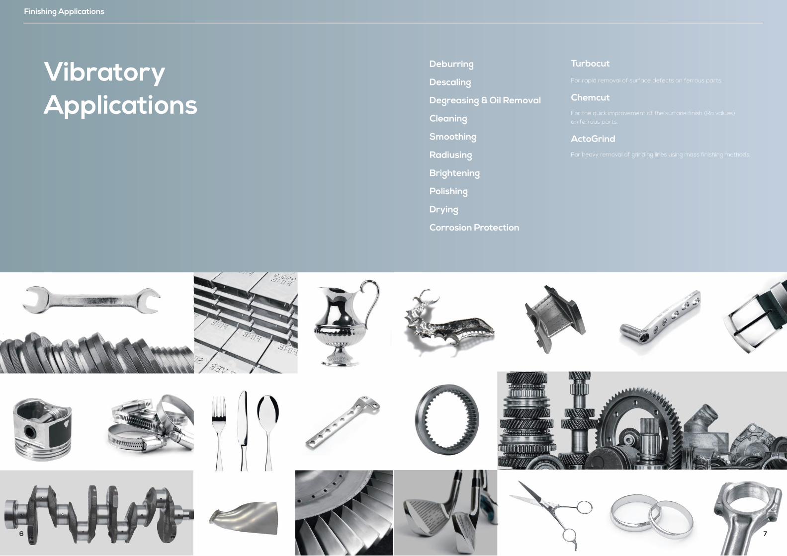
VibratoryApplications
Finishing Applications
Turbocut For rapid removal of surface defects on ferrous parts.
Chemcut For the quick improvement of the surface finish (Ra values) on ferrous parts.
ActoGrind For heavy removal of grinding lines using mass finishing methods.
Deburring
Descaling
Degreasing & Oil Removal
Cleaning
Smoothing
Radiusing
Brightening
Polishing
Drying
Corrosion Protection
7
8
Vibrota Range
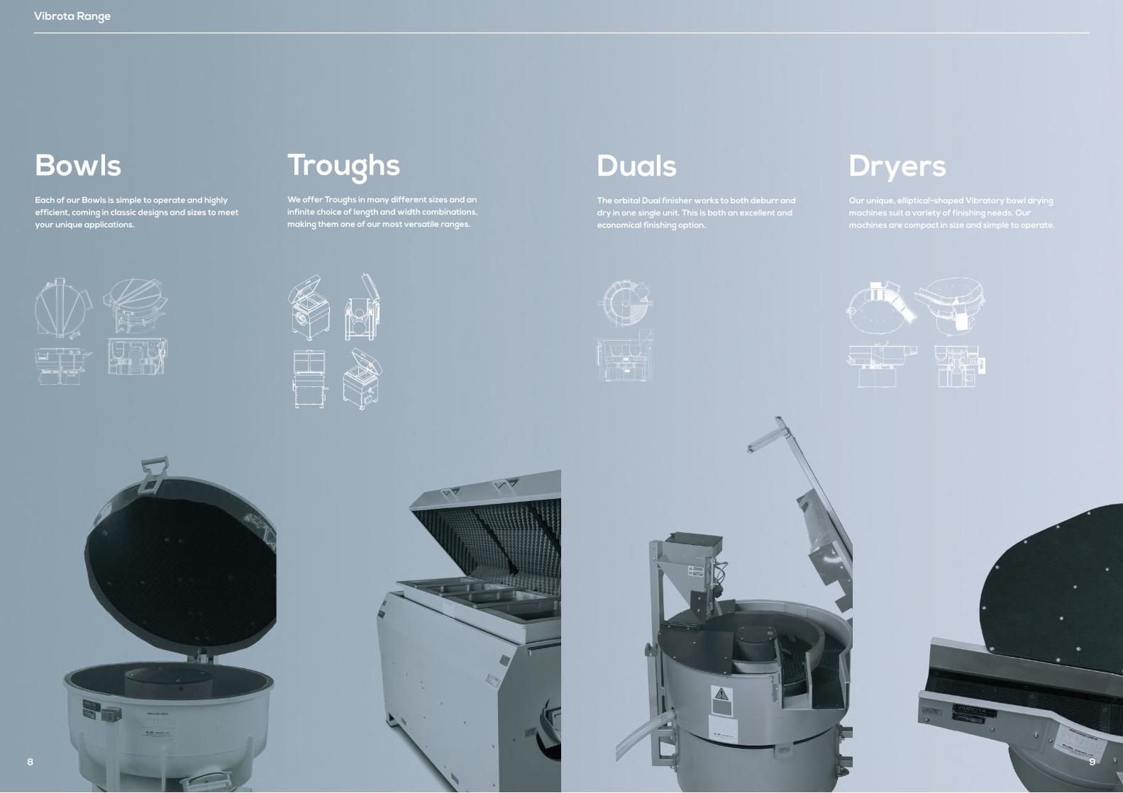
BowlsEach of our Bowls is simple to operate and highly efficient, coming in classic designs and sizes to meet your unique applications.
TroughsWe offer Troughs in many different sizes and an infinite choice of length and width combinations, making them one of our most versatile ranges.
9
DualsThe orbital Dual finisher works to both deburr and dry in one single unit. This is both an excellent and economical finishing option.
DryersOur unique, elliptical-shaped Vibratory bowl drying machines suit a variety of finishing needs. Our machines are compact in size and simple to operate.
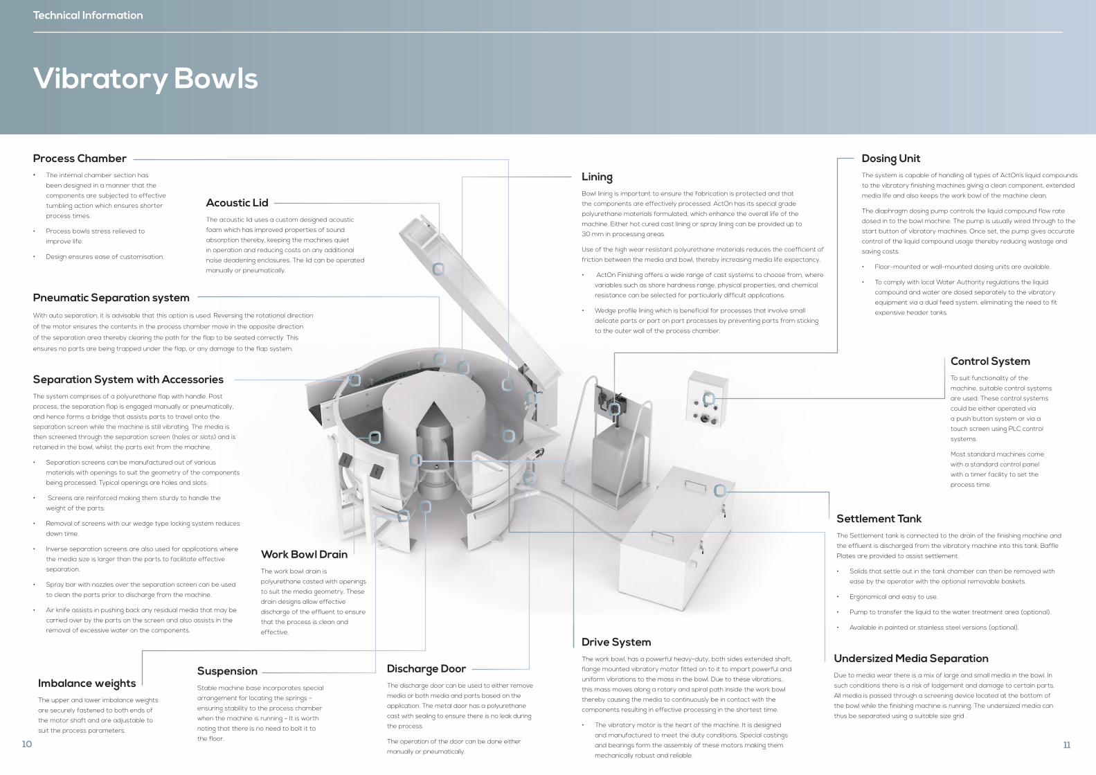
Process Chamber• The internal chamber section has
been designed in a manner that the
components are subjected to effective
tumbling action which ensures shorter
process times.
• Process bowls stress relieved to
improve life.
• Design ensures ease of customisation.
Pneumatic Separation system With auto separation, it is advisable that this option is used. Reversing the rotational direction
of the motor ensures the contents in the process chamber move in the opposite direction
of the separation area thereby clearing the path for the flap to be seated correctly. This
ensures no parts are being trapped under the flap, or any damage to the flap system.
Separation System with AccessoriesThe system comprises of a polyurethane flap with handle. Post
process, the separation flap is engaged manually or pneumatically,
and hence forms a bridge that assists parts to travel onto the
separation screen while the machine is still vibrating. The media is
then screened through the separation screen (holes or slots) and is
retained in the bowl, whilst the parts exit from the machine.
• Separation screens can be manufactured out of various
materials with openings to suit the geometry of the components
being processed. Typical openings are holes and slots.
• Screens are reinforced making them sturdy to handle the
weight of the parts.
• Removal of screens with our wedge type locking system reduces
down time.
• Inverse separation screens are also used for applications where
the media size is larger than the parts to facilitate effective
separation.
• Spray bar with nozzles over the separation screen can be used
to clean the parts prior to discharge from the machine.
• Air knife assists in pushing back any residual media that may be
carried over by the parts on the screen and also assists in the
removal of excessive water on the components.
Imbalance weights The upper and lower imbalance weights
are securely fastened to both ends of
the motor shaft and are adjustable to
suit the process parameters.
Acoustic LidThe acoustic lid uses a custom designed acoustic
foam which has improved properties of sound
absorption thereby, keeping the machines quiet
in operation and reducing costs on any additional
noise deadening enclosures. The lid can be operated
manually or pneumatically.
Work Bowl DrainThe work bowl drain is
polyurethane casted with openings
to suit the media geometry. These
drain designs allow effective
discharge of the effluent to ensure
that the process is clean and
effective.
Discharge DoorThe discharge door can be used to either remove
media or both media and parts based on the
application. The metal door has a polyurethane
cast with sealing to ensure there is no leak during
the process.
The operation of the door can be done either
manually or pneumatically.
Technical Information
SuspensionStable machine base incorporates special
arrangement for locating the springs -
ensuring stability to the process chamber
when the machine is running - It is worth
noting that there is no need to bolt it to
the floor. 10
Vibratory Bowls
Undersized Media SeparationDue to media wear there is a mix of large and small media in the bowl. In
such conditions there is a risk of lodgement and damage to certain parts.
All media is passed through a screening device located at the bottom of
the bowl while the finishing machine is running. The undersized media can
thus be separated using a suitable size grid .
LiningBowl lining is important to ensure the fabrication is protected and that
the components are effectively processed. ActOn has its special grade
polyurethane materials formulated, which enhance the overall life of the
machine. Either hot cured cast lining or spray lining can be provided up to
30 mm in processing areas.
Use of the high wear resistant polyurethane materials reduces the coefficient of
friction between the media and bowl, thereby increasing media life expectancy.
• ActOn Finishing offers a wide range of cast systems to choose from, where
variables such as shore hardness range, physical properties, and chemical
resistance can be selected for particularly difficult applications.
• Wedge profile lining which is beneficial for processes that involve small
delicate parts or part on part processes by preventing parts from sticking
to the outer wall of the process chamber.
Drive SystemThe work bowl, has a powerful heavy-duty, both sides extended shaft,
flange mounted vibratory motor fitted on to it to impart powerful and
uniform vibrations to the mass in the bowl. Due to these vibrations,
this mass moves along a rotary and spiral path inside the work bowl
thereby causing the media to continuously be in contact with the
components resulting in effective processing in the shortest time.
• The vibratory motor is the heart of the machine. It is designed
and manufactured to meet the duty conditions. Special castings
and bearings form the assembly of these motors making them
mechanically robust and reliable.
Control SystemTo suit functionality of the
machine, suitable control systems
are used. These control systems
could be either operated via
a push button system or via a
touch screen using PLC control
systems.
Most standard machines come
with a standard control panel
with a timer facility to set the
process time.
Dosing UnitThe system is capable of handling all types of ActOn’s liquid compounds
to the vibratory finishing machines giving a clean component, extended
media life and also keeps the work bowl of the machine clean.
The diaphragm dosing pump controls the liquid compound flow rate
dosed in to the bowl machine. The pump is usually wired through to the
start button of vibratory machines. Once set, the pump gives accurate
control of the liquid compound usage thereby reducing wastage and
saving costs.
• Floor-mounted or wall-mounted dosing units are available.
• To comply with local Water Authority regulations the liquid
compound and water are dosed separately to the vibratory
equipment via a dual feed system, eliminating the need to fit
expensive header tanks.
Settlement TankThe Settlement tank is connected to the drain of the finishing machine and
the effluent is discharged from the vibratory machine into this tank. Baffle
Plates are provided to assist settlement.
• Solids that settle out in the tank chamber can then be removed with
ease by the operator with the optional removable baskets.
• Ergonomical and easy to use.
• Pump to transfer the liquid to the water treatment area (optional).
• Available in painted or stainless steel versions (optional).
11
12
Each of our Bowls are simple to operate and highly efficient.
Vibratory bowls
These machines have been built to suit various customer
applications from deburring, descaling, radiusing and
cleaning to polishing and surface improvement.
We have set a high standard when designing and
building the bowl machines and are highly committed to
continuously develop our machines to suit most of the
challenging finishing applications.
Machines are built to various standard sizes. Custom
applications where size or configuration alteration is
required, ActOn engineers would be pleased to assist.
Key Benefits: British built high-quality product
Efficient in operation
Quiet in operation
High quality wear-resistant polyurethane lining
Operator friendly controls
Low maintenance
Manual / Auto functionality
Customised to suit user applications
13
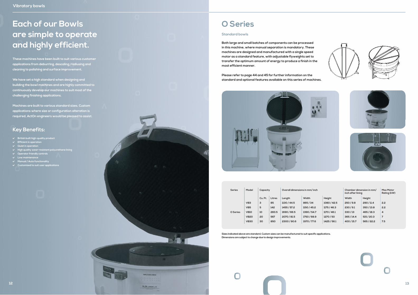
O Series
Both large and small batches of components can be processed in this machine, where manual separation is mandatory. These machines are designed and manufactured with a single speed motor as a standard feature, with adjustable flyweights set to transfer the optimum amount of energy to produce a finish in the most efficient manner.
Please refer to page 44 and 45 for further information on the standard and optional features available on this series of machines.
Series Model Capacity Overall dimensions in mm/ inch Chamber dimension in mm/ inch after lining
Max Motor Rating (kW)
Cu. Ft. Litres Length Width Height Width Height
O Series
VB3 3 85 1130 / 44.5 865 / 34 1080 / 42.5 250 / 9.8 290 / 11.4 2.2
VB5 5 142 1455 / 57.2 1150 / 45.2 1175 / 46.3 230 / 9.1 350 / 13.8 2.2
VB10 10 283.5 1690 / 66.5 1390 / 54.7 1170 / 46.1 330 / 13 465 / 18.3 4
VB20 20 567 2070 / 81.5 1750 / 68.9 1270 / 50 365 / 14.4 515 / 20.3 7
VB30 30 850 2300 / 90.6 1970 / 77.6 1425 / 56.1 400 / 15.7 565 / 22.2 7.5
A
A
SECTION A-A
A
A
SECTION A-A
Sizes indicated above are standard. Custom sizes can be manufactured to suit specific applications. Dimensions are subject to change due to design improvements.
Standard bowls
14
Vibratory bowls
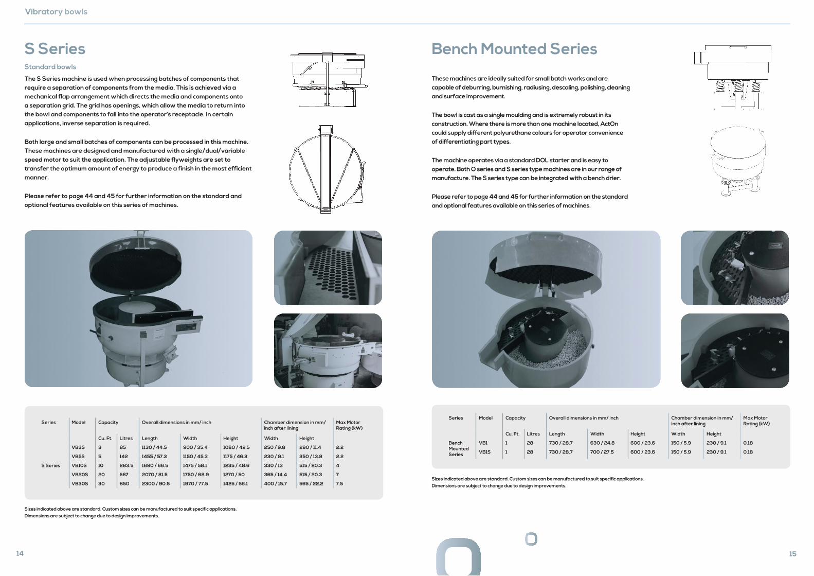
S Series Standard bowls
The S Series machine is used when processing batches of components that require a separation of components from the media. This is achieved via a mechanical flap arrangement which directs the media and components onto a separation grid. The grid has openings, which allow the media to return into the bowl and components to fall into the operator’s receptacle. In certain applications, inverse separation is required.
Both large and small batches of components can be processed in this machine. These machines are designed and manufactured with a single/dual/variable speed motor to suit the application. The adjustable flyweights are set to transfer the optimum amount of energy to produce a finish in the most efficient manner.
Please refer to page 44 and 45 for further information on the standard and optional features available on this series of machines.
Series Model Capacity Overall dimensions in mm/ inch Chamber dimension in mm/ inch after lining
Max Motor Rating (kW)
Cu. Ft. Litres Length Width Height Width Height
S Series
VB3S 3 85 1130 / 44.5 900 / 35.4 1080 / 42.5 250 / 9.8 290 / 11.4 2.2
VB5S 5 142 1455 / 57.3 1150 / 45.3 1175 / 46.3 230 / 9.1 350 / 13.8 2.2
VB10S 10 283.5 1690 / 66.5 1475 / 58.1 1235 / 48.6 330 / 13 515 / 20.3 4
VB20S 20 567 2070 / 81.5 1750 / 68.9 1270 / 50 365 / 14.4 515 / 20.3 7
VB30S 30 850 2300 / 90.5 1970 / 77.5 1425 / 56.1 400 / 15.7 565 / 22.2 7.5
Sizes indicated above are standard. Custom sizes can be manufactured to suit specific applications. Dimensions are subject to change due to design improvements.
15
Bench Mounted Series
These machines are ideally suited for small batch works and are capable of deburring, burnishing, radiusing, descaling, polishing, cleaning and surface improvement.
The bowl is cast as a single moulding and is extremely robust in its construction. Where there is more than one machine located, ActOn could supply different polyurethane colours for operator convenience of differentiating part types.
The machine operates via a standard DOL starter and is easy to operate. Both O series and S series type machines are in our range of manufacture. The S series type can be integrated with a bench drier.
Please refer to page 44 and 45 for further information on the standard and optional features available on this series of machines.
Sizes indicated above are standard. Custom sizes can be manufactured to suit specific applications. Dimensions are subject to change due to design improvements.
Series Model Capacity Overall dimensions in mm/ inch Chamber dimension in mm/ inch after lining
Max Motor Rating (kW)
Cu. Ft. Litres Length Width Height Width Height
Bench Mounted Series
VB1 1 28 730 / 28.7 630 / 24.8 600 / 23.6 150 / 5.9 230 / 9.1 0.18
VB1S 1 28 730 / 28.7 700 / 27.5 600 / 23.6 150 / 5.9 230 / 9.1 0.18
16
Vibratory bowls
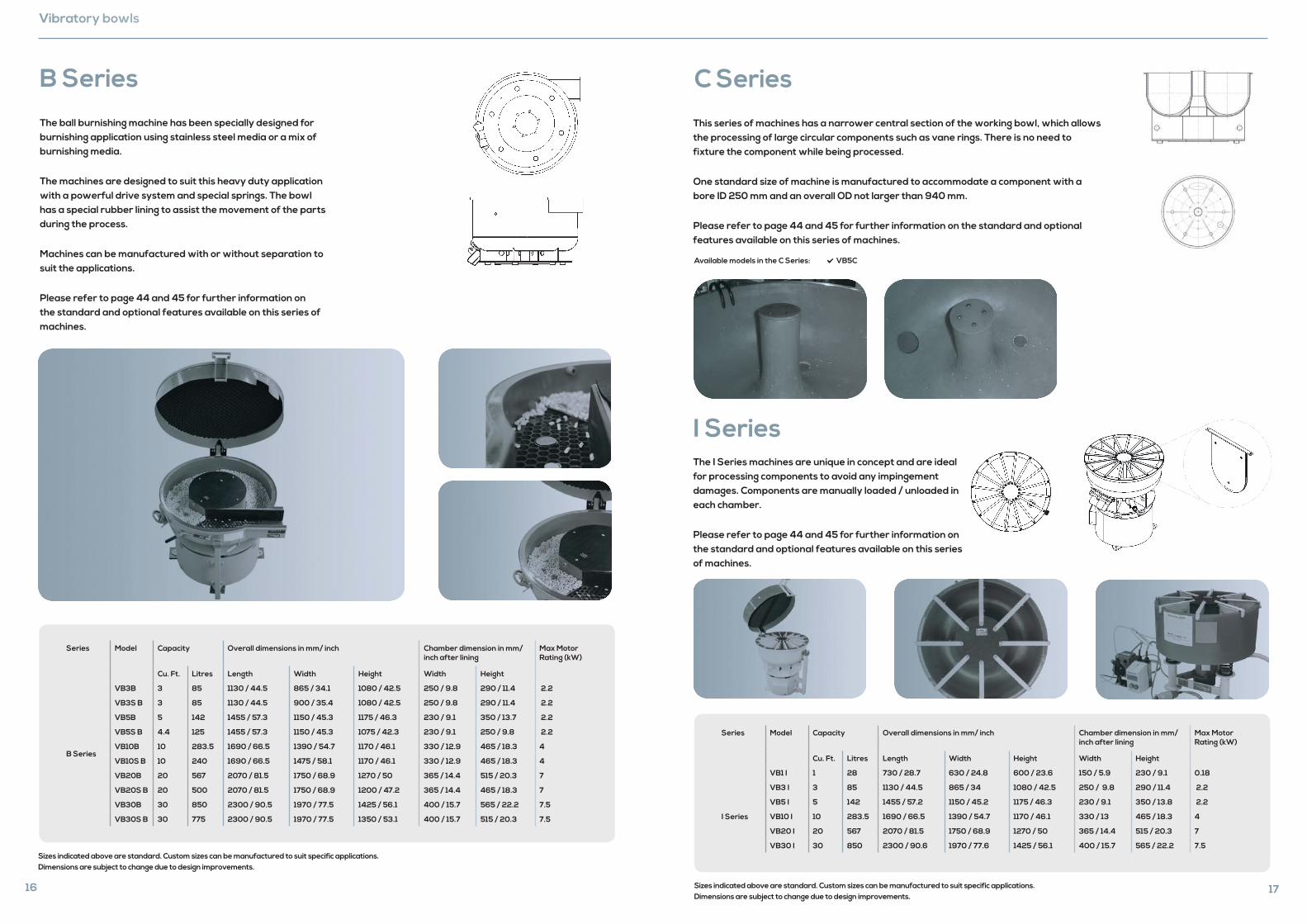
B Series
The ball burnishing machine has been specially designed for burnishing application using stainless steel media or a mix of burnishing media.
The machines are designed to suit this heavy duty application with a powerful drive system and special springs. The bowl has a special rubber lining to assist the movement of the parts during the process.
Machines can be manufactured with or without separation to suit the applications.
Please refer to page 44 and 45 for further information on the standard and optional features available on this series of machines.
Series Model Capacity Overall dimensions in mm/ inch Chamber dimension in mm/ inch after lining
Max Motor Rating (kW)
Cu. Ft. Litres Length Width Height Width Height
B Series
VB3B 3 85 1130 / 44.5 865 / 34.1 1080 / 42.5 250 / 9.8 290 / 11.4 2.2
VB3S B 3 85 1130 / 44.5 900 / 35.4 1080 / 42.5 250 / 9.8 290 / 11.4 2.2
VB5B 5 142 1455 / 57.3 1150 / 45.3 1175 / 46.3 230 / 9.1 350 / 13.7 2.2
VB5S B 4.4 125 1455 / 57.3 1150 / 45.3 1075 / 42.3 230 / 9.1 250 / 9.8 2.2
VB10B 10 283.5 1690 / 66.5 1390 / 54.7 1170 / 46.1 330 / 12.9 465 / 18.3 4
VB10S B 10 240 1690 / 66.5 1475 / 58.1 1170 / 46.1 330 / 12.9 465 / 18.3 4
VB20B 20 567 2070 / 81.5 1750 / 68.9 1270 / 50 365 / 14.4 515 / 20.3 7
VB20S B 20 500 2070 / 81.5 1750 / 68.9 1200 / 47.2 365 / 14.4 465 / 18.3 7
VB30B 30 850 2300 / 90.5 1970 / 77.5 1425 / 56.1 400 / 15.7 565 / 22.2 7.5
VB30S B 30 775 2300 / 90.5 1970 / 77.5 1350 / 53.1 400 / 15.7 515 / 20.3 7.5
STANDARD VB5S BURNISHING VB5S-B
STANDARD VB5S BURNISHING VB5S-B
Sizes indicated above are standard. Custom sizes can be manufactured to suit specific applications. Dimensions are subject to change due to design improvements.
17
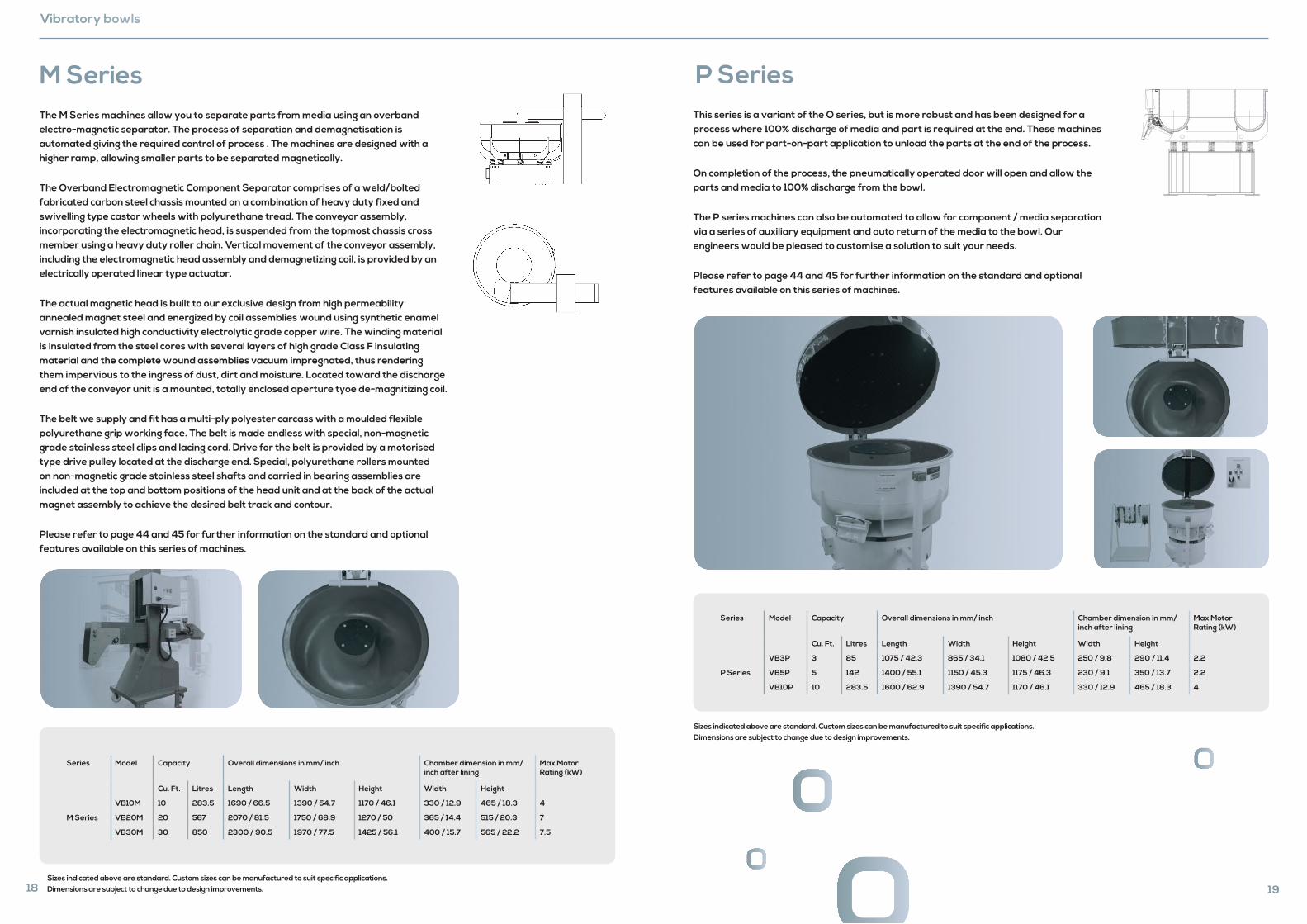
C Series
This series of machines has a narrower central section of the working bowl, which allows the processing of large circular components such as vane rings. There is no need to fixture the component while being processed.
One standard size of machine is manufactured to accommodate a component with a bore ID 250 mm and an overall OD not larger than 940 mm.
Please refer to page 44 and 45 for further information on the standard and optional features available on this series of machines.
Available models in the C Series: VB5C
I SeriesThe I Series machines are unique in concept and are ideal for processing components to avoid any impingement damages. Components are manually loaded / unloaded in each chamber.
Please refer to page 44 and 45 for further information on the standard and optional features available on this series of machines.
Series Model Capacity Overall dimensions in mm/ inch Chamber dimension in mm/ inch after lining
Max Motor Rating (kW)
Cu. Ft. Litres Length Width Height Width Height
VB1 I 1 28 730 / 28.7 630 / 24.8 600 / 23.6 150 / 5.9 230 / 9.1 0.18
I Series
VB3 I 3 85 1130 / 44.5 865 / 34 1080 / 42.5 250 / 9.8 290 / 11.4 2.2
VB5 I 5 142 1455 / 57.2 1150 / 45.2 1175 / 46.3 230 / 9.1 350 / 13.8 2.2
VB10 I 10 283.5 1690 / 66.5 1390 / 54.7 1170 / 46.1 330 / 13 465 / 18.3 4
VB20 I 20 567 2070 / 81.5 1750 / 68.9 1270 / 50 365 / 14.4 515 / 20.3 7
VB30 I 30 850 2300 / 90.6 1970 / 77.6 1425 / 56.1 400 / 15.7 565 / 22.2 7.5
B
BSECTION B-B
Sizes indicated above are standard. Custom sizes can be manufactured to suit specific applications. Dimensions are subject to change due to design improvements.
Vibratory bowls
M SeriesThe M Series machines allow you to separate parts from media using an overband electro-magnetic separator. The process of separation and demagnetisation is automated giving the required control of process . The machines are designed with a higher ramp, allowing smaller parts to be separated magnetically.
The Overband Electromagnetic Component Separator comprises of a weld/bolted fabricated carbon steel chassis mounted on a combination of heavy duty fixed and swivelling type castor wheels with polyurethane tread. The conveyor assembly, incorporating the electromagnetic head, is suspended from the topmost chassis cross member using a heavy duty roller chain. Vertical movement of the conveyor assembly, including the electromagnetic head assembly and demagnetizing coil, is provided by an electrically operated linear type actuator.
The actual magnetic head is built to our exclusive design from high permeability annealed magnet steel and energized by coil assemblies wound using synthetic enamel varnish insulated high conductivity electrolytic grade copper wire. The winding material is insulated from the steel cores with several layers of high grade Class F insulating material and the complete wound assemblies vacuum impregnated, thus rendering them impervious to the ingress of dust, dirt and moisture. Located toward the discharge end of the conveyor unit is a mounted, totally enclosed aperture tyoe de-magnitizing coil.
The belt we supply and fit has a multi-ply polyester carcass with a moulded flexible polyurethane grip working face. The belt is made endless with special, non-magnetic grade stainless steel clips and lacing cord. Drive for the belt is provided by a motorised type drive pulley located at the discharge end. Special, polyurethane rollers mounted on non-magnetic grade stainless steel shafts and carried in bearing assemblies are included at the top and bottom positions of the head unit and at the back of the actual magnet assembly to achieve the desired belt track and contour.
Please refer to page 44 and 45 for further information on the standard and optional features available on this series of machines.
Series Model Capacity Overall dimensions in mm/ inch Chamber dimension in mm/ inch after lining
Max Motor Rating (kW)
Cu. Ft. Litres Length Width Height Width Height
M Series
VB10M 10 283.5 1690 / 66.5 1390 / 54.7 1170 / 46.1 330 / 12.9 465 / 18.3 4
VB20M 20 567 2070 / 81.5 1750 / 68.9 1270 / 50 365 / 14.4 515 / 20.3 7
VB30M 30 850 2300 / 90.5 1970 / 77.5 1425 / 56.1 400 / 15.7 565 / 22.2 7.5
18Sizes indicated above are standard. Custom sizes can be manufactured to suit specific applications. Dimensions are subject to change due to design improvements. 19
P SeriesThis series is a variant of the O series, but is more robust and has been designed for a process where 100% discharge of media and part is required at the end. These machines can be used for part-on-part application to unload the parts at the end of the process.
On completion of the process, the pneumatically operated door will open and allow the parts and media to 100% discharge from the bowl.
The P series machines can also be automated to allow for component / media separation via a series of auxiliary equipment and auto return of the media to the bowl. Our engineers would be pleased to customise a solution to suit your needs.
Please refer to page 44 and 45 for further information on the standard and optional features available on this series of machines.
Series Model Capacity Overall dimensions in mm/ inch Chamber dimension in mm/ inch after lining
Max Motor Rating (kW)
Cu. Ft. Litres Length Width Height Width Height
P Series
VB3P 3 85 1075 / 42.3 865 / 34.1 1080 / 42.5 250 / 9.8 290 / 11.4 2.2
VB5P 5 142 1400 / 55.1 1150 / 45.3 1175 / 46.3 230 / 9.1 350 / 13.7 2.2
VB10P 10 283.5 1600 / 62.9 1390 / 54.7 1170 / 46.1 330 / 12.9 465 / 18.3 4
Sizes indicated above are standard. Custom sizes can be manufactured to suit specific applications. Dimensions are subject to change due to design improvements.
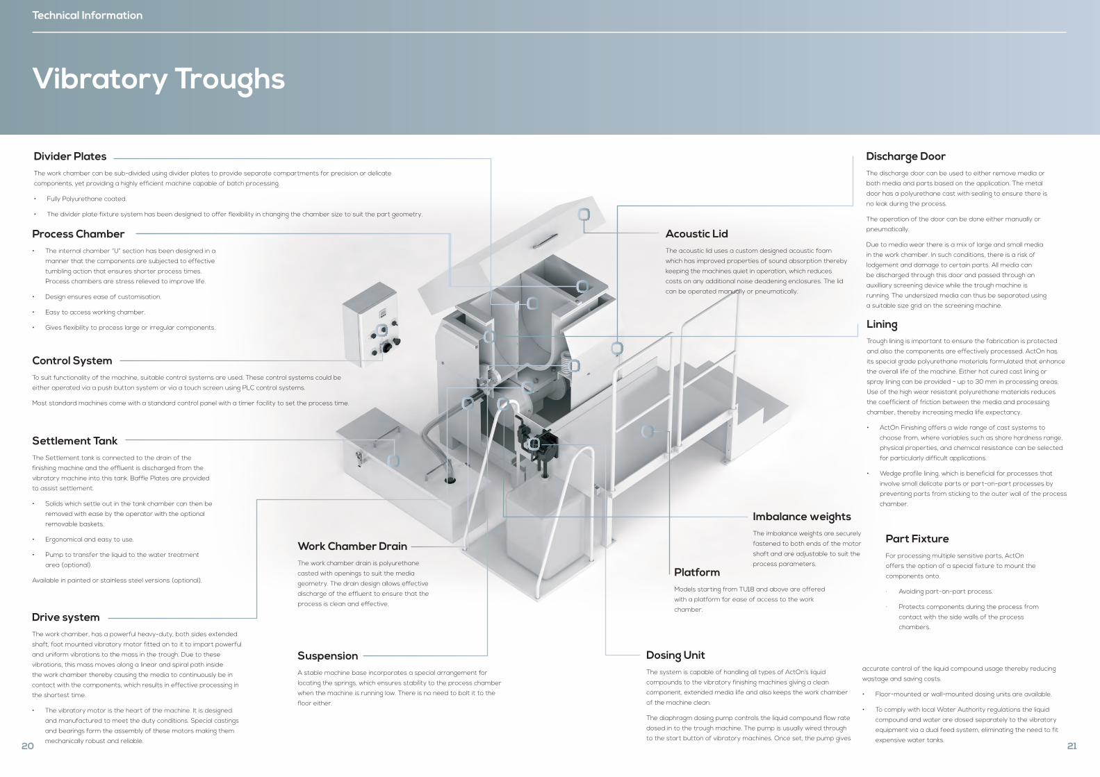
Technical Information
Vibratory Troughs
Process Chamber• The internal chamber “U” section has been designed in a
manner that the components are subjected to effective
tumbling action that ensures shorter process times.
Process chambers are stress relieved to improve life.
• Design ensures ease of customisation.
• Easy to access working chamber.
• Gives flexibility to process large or irregular components.
Work Chamber DrainThe work chamber drain is polyurethane
casted with openings to suit the media
geometry. The drain design allows effective
discharge of the effluent to ensure that the
process is clean and effective.
Drive systemThe work chamber, has a powerful heavy-duty, both sides extended
shaft, foot mounted vibratory motor fitted on to it to impart powerful
and uniform vibrations to the mass in the trough. Due to these
vibrations, this mass moves along a linear and spiral path inside
the work chamber thereby causing the media to continuously be in
contact with the components, which results in effective processing in
the shortest time.
• The vibratory motor is the heart of the machine. It is designed
and manufactured to meet the duty conditions. Special castings
and bearings form the assembly of these motors making them
mechanically robust and reliable.
SuspensionA stable machine base incorporates a special arrangement for
locating the springs, which ensures stability to the process chamber
when the machine is running low. There is no need to bolt it to the
floor either.
Control SystemTo suit functionality of the machine, suitable control systems are used. These control systems could be
either operated via a push button system or via a touch screen using PLC control systems.
Most standard machines come with a standard control panel with a timer facility to set the process time.
Divider PlatesThe work chamber can be sub-divided using divider plates to provide separate compartments for precision or delicate
components, yet providing a highly efficient machine capable of batch processing.
• Fully Polyurethane coated.
• The divider plate fixture system has been designed to offer flexibility in changing the chamber size to suit the part geometry.
Settlement TankThe Settlement tank is connected to the drain of the
finishing machine and the effluent is discharged from the
vibratory machine into this tank. Baffle Plates are provided
to assist settlement.
• Solids which settle out in the tank chamber can then be
removed with ease by the operator with the optional
removable baskets.
• Ergonomical and easy to use.
• Pump to transfer the liquid to the water treatment
area (optional).
Available in painted or stainless steel versions (optional).
20
Part FixtureFor processing multiple sensitive parts, ActOn
offers the option of a special fixture to mount the
components onto.
· Avoiding part-on-part process.
· Protects components during the process from
contact with the side walls of the process
chambers.
LiningTrough lining is important to ensure the fabrication is protected
and also the components are effectively processed. ActOn has
its special grade polyurethane materials formulated that enhance
the overall life of the machine. Either hot cured cast lining or
spray lining can be provided - up to 30 mm in processing areas.
Use of the high wear resistant polyurethane materials reduces
the coefficient of friction between the media and processing
chamber, thereby increasing media life expectancy.
• ActOn Finishing offers a wide range of cast systems to
choose from, where variables such as shore hardness range,
physical properties, and chemical resistance can be selected
for particularly difficult applications.
• Wedge profile lining, which is beneficial for processes that
involve small delicate parts or part-on-part processes by
preventing parts from sticking to the outer wall of the process
chamber.
Imbalance weights The imbalance weights are securely
fastened to both ends of the motor
shaft and are adjustable to suit the
process parameters.
Dosing UnitThe system is capable of handling all types of ActOn’s liquid
compounds to the vibratory finishing machines giving a clean
component, extended media life and also keeps the work chamber
of the machine clean.
The diaphragm dosing pump controls the liquid compound flow rate
dosed in to the trough machine. The pump is usually wired through
to the start button of vibratory machines. Once set, the pump gives
accurate control of the liquid compound usage thereby reducing
wastage and saving costs.
• Floor-mounted or wall-mounted dosing units are available.
• To comply with local Water Authority regulations the liquid
compound and water are dosed separately to the vibratory
equipment via a dual feed system, eliminating the need to fit
expensive water tanks.
Discharge DoorThe discharge door can be used to either remove media or
both media and parts based on the application. The metal
door has a polyurethane cast with sealing to ensure there is
no leak during the process.
The operation of the door can be done either manually or
pneumatically.
Due to media wear there is a mix of large and small media
in the work chamber. In such conditions, there is a risk of
lodgement and damage to certain parts. All media can
be discharged through this door and passed through an
auxilliary screening device while the trough machine is
running. The undersized media can thus be separated using
a suitable size grid on the screening machine.
Acoustic LidThe acoustic lid uses a custom designed acoustic foam
which has improved properties of sound absorption thereby
keeping the machines quiet in operation, which reduces
costs on any additional noise deadening enclosures. The lid
can be operated manually or pneumatically.
PlatformModels starting from TU18 and above are offered
with a platform for ease of access to the work
chamber.
21
The trough machine is perfect for larger, longer and irregular-shaped components.
Troughs Range
22
Offered in various standard sizes and a choice of
combination of lengths and widths, the troughs are
the most versatile machines. These machines have
been built to suit various customer applications from
deburring, descaling, radiusing and cleaning to polishing
and surface improvement.
We have set a high standard when designing and
building the trough machines and are highly committed
to continuously develop our machines to suit most of the
challenging finishing applications.
Machines are built to various standard sizes. If there are
custom applications where size or configuration alteration
is required, ActOn engineers would be pleased to assist.
Key Benefits: British built, high-quality product
Efficient in operation
Quiet in operation
High quality, wear resistant polyurethane lining
Operator friendly controls
Low maintenance
Manual / Auto functionality
Customised to suit user applications
Several processing chambers can be made with use of dividers
Solutions include both batch type and continuous online systems
23
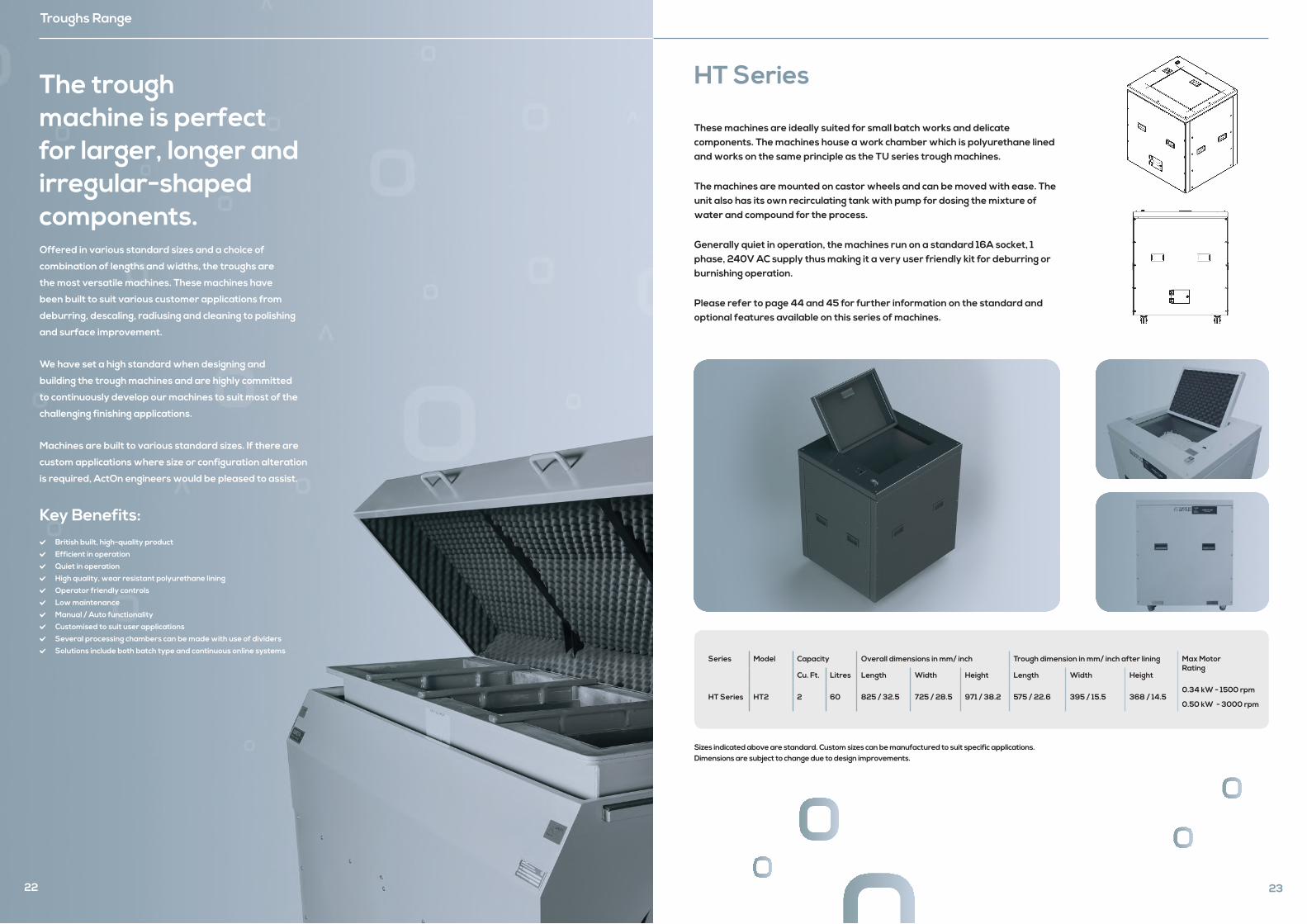
HT Series
These machines are ideally suited for small batch works and delicate components. The machines house a work chamber which is polyurethane lined and works on the same principle as the TU series trough machines.
The machines are mounted on castor wheels and can be moved with ease. The unit also has its own recirculating tank with pump for dosing the mixture of water and compound for the process.
Generally quiet in operation, the machines run on a standard 16A socket, 1 phase, 240V AC supply thus making it a very user friendly kit for deburring or burnishing operation.
Please refer to page 44 and 45 for further information on the standard and optional features available on this series of machines.
Series Model Capacity Overall dimensions in mm/ inch Trough dimension in mm/ inch after lining Max Motor Rating
Cu. Ft. Litres Length Width Height Length Width Height
HT Series HT2 2 60 825 / 32.5 725 / 28.5 971 / 38.2 575 / 22.6 395 / 15.5 368 / 14.50.34 kW - 1500 rpm
0.50 kW - 3000 rpm
Sizes indicated above are standard. Custom sizes can be manufactured to suit specific applications. Dimensions are subject to change due to design improvements.
24
Troughs Range
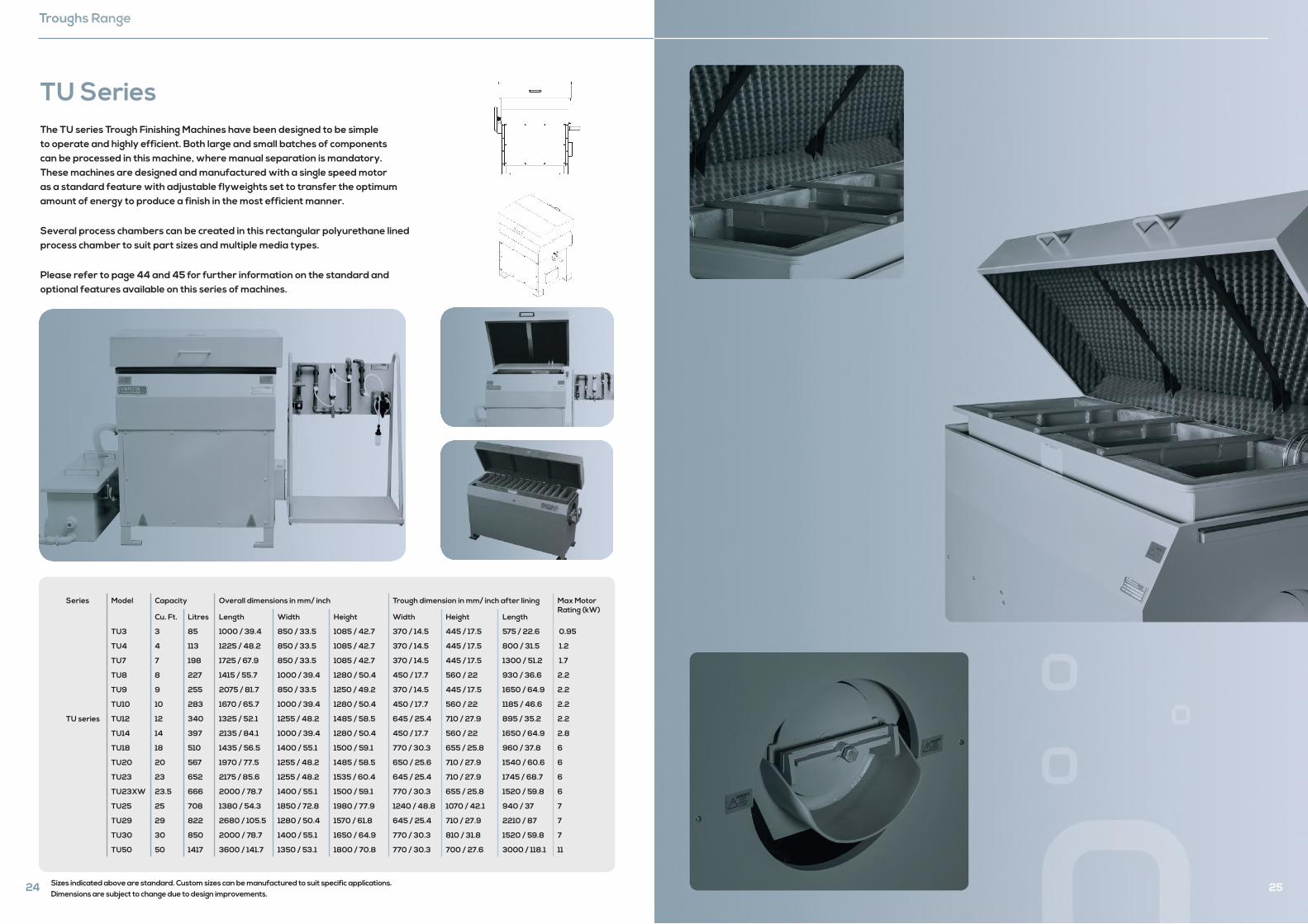
TU SeriesThe TU series Trough Finishing Machines have been designed to be simple to operate and highly efficient. Both large and small batches of components can be processed in this machine, where manual separation is mandatory. These machines are designed and manufactured with a single speed motor as a standard feature with adjustable flyweights set to transfer the optimum amount of energy to produce a finish in the most efficient manner.
Several process chambers can be created in this rectangular polyurethane lined process chamber to suit part sizes and multiple media types.
Please refer to page 44 and 45 for further information on the standard and optional features available on this series of machines.
Series Model Capacity Overall dimensions in mm/ inch Trough dimension in mm/ inch after lining Max Motor Rating (kW)
Cu. Ft. Litres Length Width Height Width Height Length
TU series
TU3 3 85 1000 / 39.4 850 / 33.5 1085 / 42.7 370 / 14.5 445 / 17.5 575 / 22.6 0.95
TU4 4 113 1225 / 48.2 850 / 33.5 1085 / 42.7 370 / 14.5 445 / 17.5 800 / 31.5 1.2
TU7 7 198 1725 / 67.9 850 / 33.5 1085 / 42.7 370 / 14.5 445 / 17.5 1300 / 51.2 1.7
TU8 8 227 1415 / 55.7 1000 / 39.4 1280 / 50.4 450 / 17.7 560 / 22 930 / 36.6 2.2
TU9 9 255 2075 / 81.7 850 / 33.5 1250 / 49.2 370 / 14.5 445 / 17.5 1650 / 64.9 2.2
TU10 10 283 1670 / 65.7 1000 / 39.4 1280 / 50.4 450 / 17.7 560 / 22 1185 / 46.6 2.2
TU12 12 340 1325 / 52.1 1255 / 48.2 1485 / 58.5 645 / 25.4 710 / 27.9 895 / 35.2 2.2
TU14 14 397 2135 / 84.1 1000 / 39.4 1280 / 50.4 450 / 17.7 560 / 22 1650 / 64.9 2.8
TU18 18 510 1435 / 56.5 1400 / 55.1 1500 / 59.1 770 / 30.3 655 / 25.8 960 / 37.8 6
TU20 20 567 1970 / 77.5 1255 / 48.2 1485 / 58.5 650 / 25.6 710 / 27.9 1540 / 60.6 6
TU23 23 652 2175 / 85.6 1255 / 48.2 1535 / 60.4 645 / 25.4 710 / 27.9 1745 / 68.7 6
TU23XW 23.5 666 2000 / 78.7 1400 / 55.1 1500 / 59.1 770 / 30.3 655 / 25.8 1520 / 59.8 6
TU25 25 708 1380 / 54.3 1850 / 72.8 1980 / 77.9 1240 / 48.8 1070 / 42.1 940 / 37 7
TU29 29 822 2680 / 105.5 1280 / 50.4 1570 / 61.8 645 / 25.4 710 / 27.9 2210 / 87 7
TU30 30 850 2000 / 78.7 1400 / 55.1 1650 / 64.9 770 / 30.3 810 / 31.8 1520 / 59.8 7
TU50 50 1417 3600 / 141.7 1350 / 53.1 1800 / 70.8 770 / 30.3 700 / 27.6 3000 / 118.1 11
Sizes indicated above are standard. Custom sizes can be manufactured to suit specific applications. Dimensions are subject to change due to design improvements.
25
Technical Information
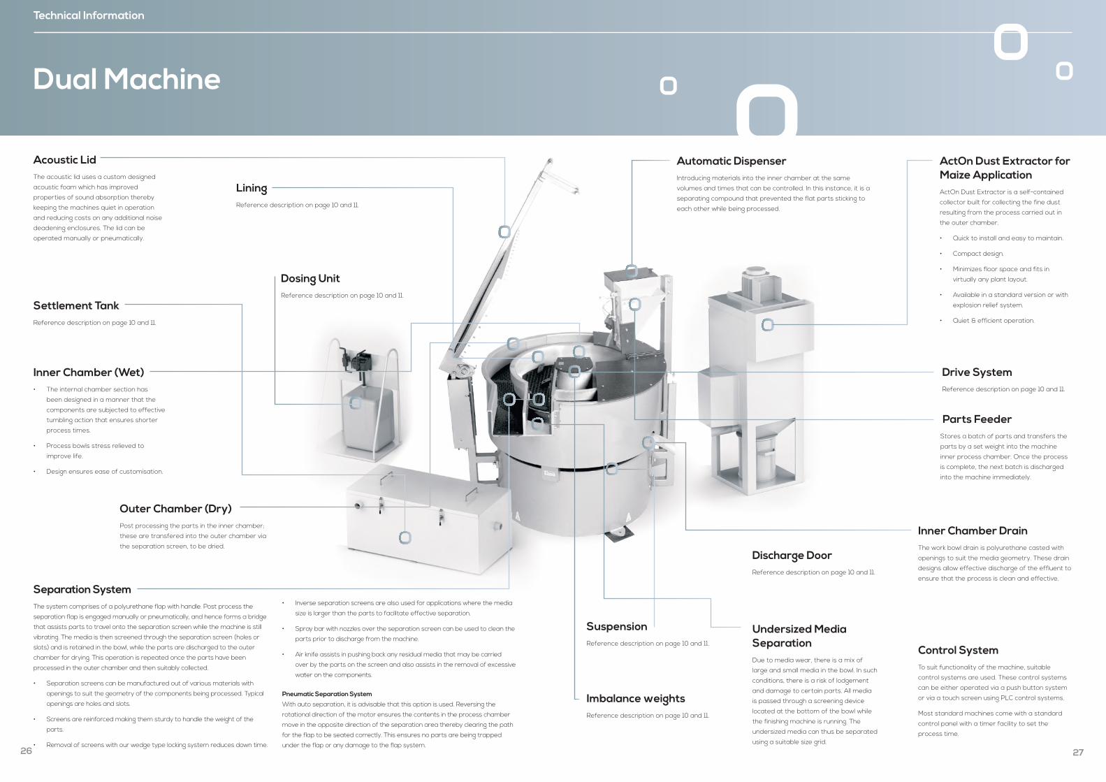
Dual Machine
Inner Chamber (Wet)• The internal chamber section has
been designed in a manner that the
components are subjected to effective
tumbling action that ensures shorter
process times.
• Process bowls stress relieved to
improve life.
• Design ensures ease of customisation.
LiningReference description on page 10 and 11.
Separation SystemThe system comprises of a polyurethane flap with handle. Post process the
separation flap is engaged manually or pneumatically, and hence forms a bridge
that assists parts to travel onto the separation screen while the machine is still
vibrating. The media is then screened through the separation screen (holes or
slots) and is retained in the bowl, while the parts are discharged to the outer
chamber for drying. This operation is repeated once the parts have been
processed in the outer chamber and then suitably collected.
• Separation screens can be manufactured out of various materials with
openings to suit the geometry of the components being processed. Typical
openings are holes and slots.
• Screens are reinforced making them sturdy to handle the weight of the
parts.
• Removal of screens with our wedge type locking system reduces down time.
• Inverse separation screens are also used for applications where the media
size is larger than the parts to facilitate effective separation.
• Spray bar with nozzles over the separation screen can be used to clean the
parts prior to discharge from the machine.
• Air knife assists in pushing back any residual media that may be carried
over by the parts on the screen and also assists in the removal of excessive
water on the components.
Pneumatic Separation System
With auto separation, it is advisable that this option is used. Reversing the
rotational direction of the motor ensures the contents in the process chamber
move in the opposite direction of the separation area thereby clearing the path
for the flap to be seated correctly. This ensures no parts are being trapped
under the flap or any damage to the flap system.
Settlement Tank Reference description on page 10 and 11.
Dosing UnitReference description on page 10 and 11.
Outer Chamber (Dry) Post processing the parts in the inner chamber;
these are transfered into the outer chamber via
the separation screen, to be dried.
Acoustic LidThe acoustic lid uses a custom designed
acoustic foam which has improved
properties of sound absorption thereby
keeping the machines quiet in operation
and reducing costs on any additional noise
deadening enclosures. The lid can be
operated manually or pneumatically.
26
Imbalance weights Reference description on page 10 and 11.
Automatic Dispenser Introducing materials into the inner chamber at the same
volumes and times that can be controlled. In this instance, it is a
separating compound that prevented the flat parts sticking to
each other while being processed.
Drive SystemReference description on page 10 and 11.
Discharge DoorReference description on page 10 and 11.
Inner Chamber Drain The work bowl drain is polyurethane casted with
openings to suit the media geometry. These drain
designs allow effective discharge of the effluent to
ensure that the process is clean and effective.
Undersized Media SeparationDue to media wear, there is a mix of
large and small media in the bowl. In such
conditions, there is a risk of lodgement
and damage to certain parts. All media
is passed through a screening device
located at the bottom of the bowl while
the finishing machine is running. The
undersized media can thus be separated
using a suitable size grid.
Parts FeederStores a batch of parts and transfers the
parts by a set weight into the machine
inner process chamber. Once the process
is complete, the next batch is discharged
into the machine immediately.
ActOn Dust Extractor for Maize ApplicationActOn Dust Extractor is a self-contained
collector built for collecting the fine dust
resulting from the process carried out in
the outer chamber.
• Quick to install and easy to maintain.
• Compact design.
• Minimizes floor space and fits in
virtually any plant layout.
• Available in a standard version or with
explosion relief system.
• Quiet & efficient operation.
SuspensionReference description on page 10 and 11.
Control SystemTo suit functionality of the machine, suitable
control systems are used. These control systems
can be either operated via a push button system
or via a touch screen using PLC control systems.
Most standard machines come with a standard
control panel with a timer facility to set the
process time.
27
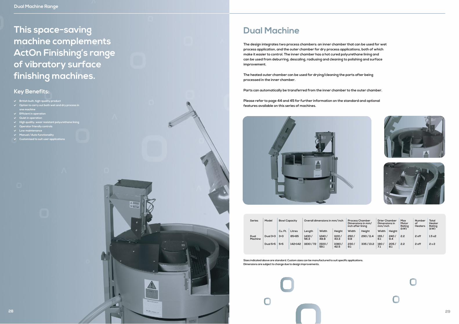
This space-saving machine complements ActOn Finishing’s range of vibratory surface finishing machines.
Dual Machine Range
28
Key Benefits: British built, high-quality product
Option to carry out both wet and dry process in
one machine
Efficient in operation
Quiet in operation
High quality, wear resistant polyurethane lining
Operator friendly controls
Low maintenance
Manual / Auto functionality
Customised to suit user applications
Dual MachineThe design integrates two process chambers: an inner chamber that can be used for wet process application, and the outer chamber for dry process applications, both of which make it easier to control. The inner chamber has a hot cured polyurethane lining and can be used from deburring, descaling, radiusing and cleaning to polishing and surface improvement.
The heated outer chamber can be used for drying/cleaning the parts after being processed in the inner chamber.
Parts can automatically be transferred from the inner chamber to the outer chamber.
Please refer to page 44 and 45 for further information on the standard and optional features available on this series of machines.
Series Model Bowl Capacity Overall dimensions in mm/ inch Process Chamber Dimensions in mm/ inch after lining
Drier Chamber Dimensions in mm/ inch
Max Motor Rating (kW)
Number of Heaters
Total Heater Rating (kW)
Cu. Ft. Litres Length Width Height Width Height Width Height
Dual Machine
Dual 3+3 3+3 85+85 1430 / 56.3
1240 / 48.8
1100 / 43.3
250 / 9.8
290 / 11.4 155 / 6.1
240 / 9.4
2.2 2 off 1.5 x2
Dual 5+5 5+5 142+142 1830 / 72 1500 / 59.1
1080 / 42.5
230 / 9.1
335 / 13.2 180 / 7.1
205 / 8.1
2.2 2 off 2 x 2
29
Sizes indicated above are standard. Custom sizes can be manufactured to suit specific applications. Dimensions are subject to change due to design improvements.
Technical Information
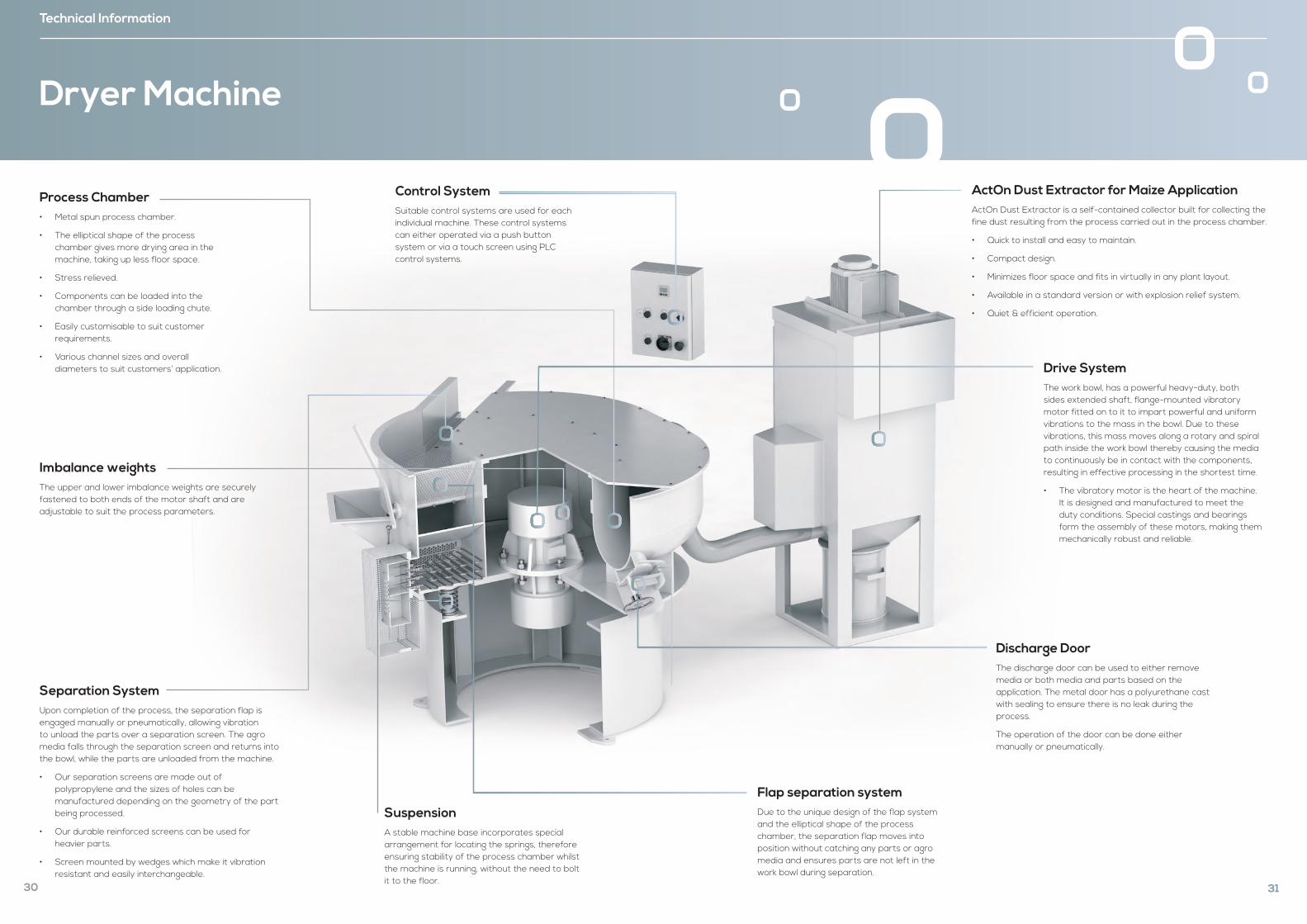
Dryer Machine
Process Chamber• Metal spun process chamber.
• The elliptical shape of the process chamber gives more drying area in the machine, taking up less floor space.
• Stress relieved.
• Components can be loaded into the chamber through a side loading chute.
• Easily customisable to suit customer requirements.
• Various channel sizes and overall diameters to suit customers’ application.
Separation SystemUpon completion of the process, the separation flap is engaged manually or pneumatically, allowing vibration to unload the parts over a separation screen. The agro media falls through the separation screen and returns into the bowl, while the parts are unloaded from the machine.
• Our separation screens are made out of polypropylene and the sizes of holes can be manufactured depending on the geometry of the part being processed.
• Our durable reinforced screens can be used for heavier parts.
• Screen mounted by wedges which make it vibration resistant and easily interchangeable.
SuspensionA stable machine base incorporates special arrangement for locating the springs, therefore ensuring stability of the process chamber whilst the machine is running, without the need to bolt it to the floor.
Imbalance weights The upper and lower imbalance weights are securely fastened to both ends of the motor shaft and are adjustable to suit the process parameters.
Control System Suitable control systems are used for each individual machine. These control systems can either operated via a push button system or via a touch screen using PLC control systems.
30
Drive SystemThe work bowl, has a powerful heavy-duty, both sides extended shaft, flange-mounted vibratory motor fitted on to it to impart powerful and uniform vibrations to the mass in the bowl. Due to these vibrations, this mass moves along a rotary and spiral path inside the work bowl thereby causing the media to continuously be in contact with the components, resulting in effective processing in the shortest time.
• The vibratory motor is the heart of the machine. It is designed and manufactured to meet the duty conditions. Special castings and bearings form the assembly of these motors, making them mechanically robust and reliable.
Flap separation system Due to the unique design of the flap system and the elliptical shape of the process chamber, the separation flap moves into position without catching any parts or agro media and ensures parts are not left in the work bowl during separation.
ActOn Dust Extractor for Maize ApplicationActOn Dust Extractor is a self-contained collector built for collecting the fine dust resulting from the process carried out in the process chamber.
• Quick to install and easy to maintain.
• Compact design.
• Minimizes floor space and fits in virtually in any plant layout.
• Available in a standard version or with explosion relief system.
• Quiet & efficient operation.
Discharge DoorThe discharge door can be used to either remove media or both media and parts based on the application. The metal door has a polyurethane cast with sealing to ensure there is no leak during the process.
The operation of the door can be done either manually or pneumatically.
31
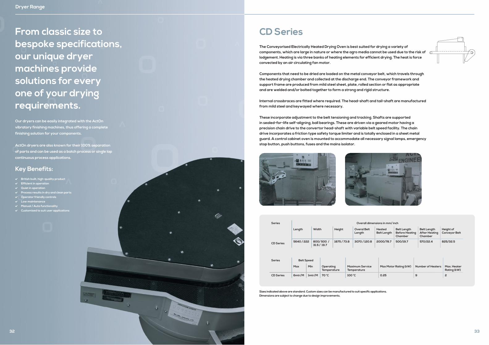
From classic size to bespoke specifications, our unique dryer machines provide solutions for every one of your drying requirements.
Dryer Range
32
Our dryers can be easily integrated with the ActOn
vibratory finishing machines, thus offering a complete
finishing solution for your components.
ActOn dryers are also known for their 100% separation
of parts and can be used as a batch process or single lap
continuous process applications.
Key Benefits: British built, high-quality product
Efficient in operation
Quiet in operation
Process results in dry and clean parts
Operator friendly controls
Low maintenance
Manual / Auto functionality
Customised to suit user applications
33
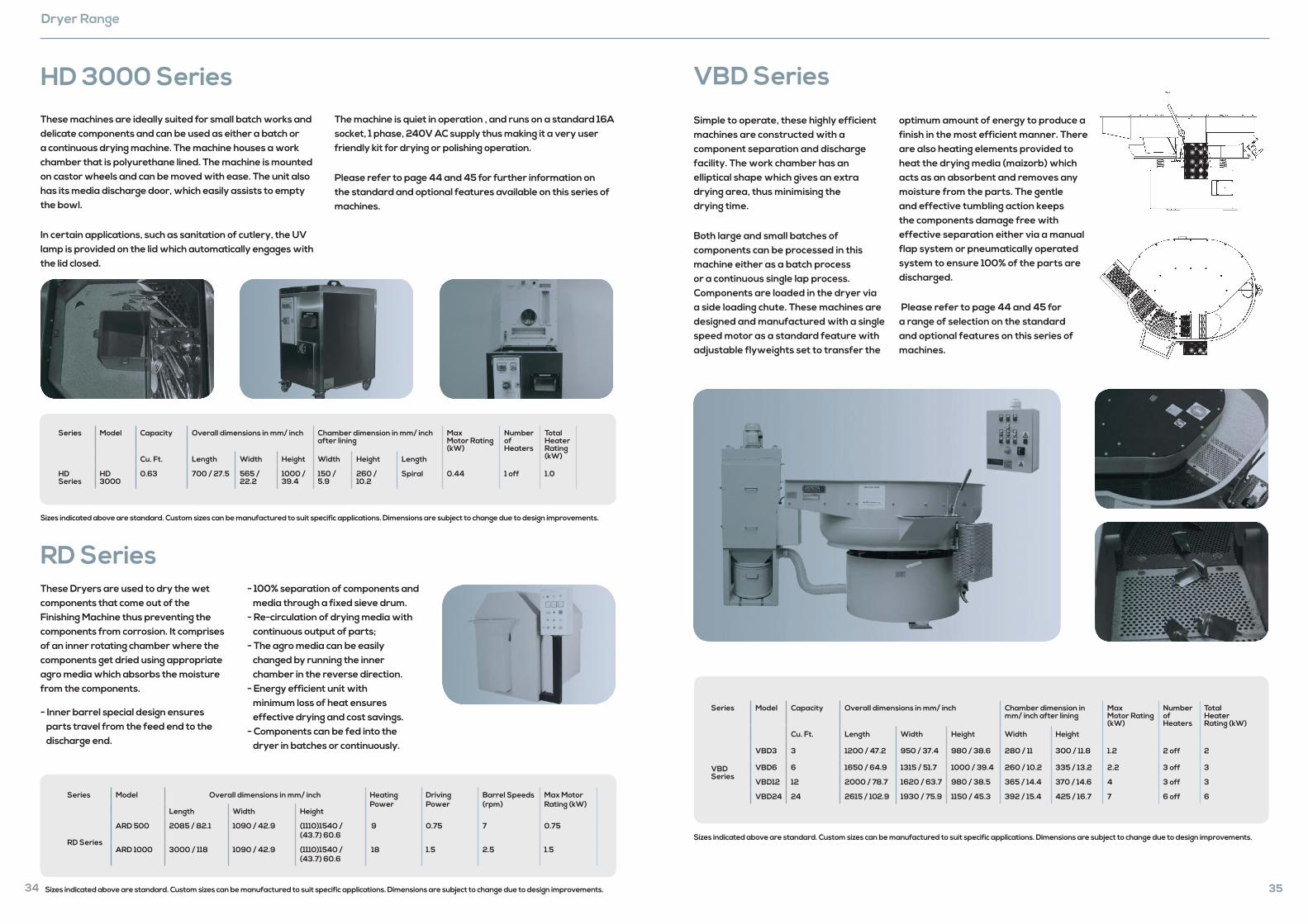
CD SeriesThe Conveyorised Electrically Heated Drying Oven is best suited for drying a variety of components, which are large in nature or where the agro media cannot be used due to the risk of lodgement. Heating is via three banks of heating elements for efficient drying. The heat is force convected by an air circulating fan motor.
Components that need to be dried are loaded on the metal conveyor belt, which travels through the heated drying chamber and collected at the discharge end. The conveyor framework and support frame are produced from mild steel sheet, plate, rolled section or flat as appropriate and are welded and/or bolted together to form a strong and rigid structure.
Internal crossbraces are fitted where required. The head-shaft and tail-shaft are manufactured from mild steel and keywayed where necessary.
These incorporate adjustment to the belt tensioning and tracking. Shafts are supported in sealed-for-life self-aligning, ball bearings. These are driven via a geared motor having a precision chain drive to the convertor head-shaft with variable belt speed facility. The chain drive incorporates a friction type safety torque limiter and is totally enclosed in a sheet metal guard. A control cabinet oven is mounted to accommodate all necessary signal lamps, emergency stop button, push buttons, fuses and the mains isolator.
Series Overall dimensions in mm/ inch
Length Width Height Overal Belt Length
Heated Belt Length
Belt Length Before Heating Chamber
Belt Length After Heating Chamber
Height of Conveyor Belt
CD Series 5640 / 222 800/ 500 / 31.5 / 19.7
1875 / 73.8 3070 / 120.8 2000/78.7 500/19.7 570/22.4 825/32.5
Series Belt Speed
Max Min Operating Temperature
Maximum Service Temperature
Max Motor Rating (kW) Number of Heaters Max. Heater Rating (kW)
CD Series 6mtr/M 1mtr/M 70 °C 100 °C 0.25 9 2
Sizes indicated above are standard. Custom sizes can be manufactured to suit specific applications. Dimensions are subject to change due to design improvements.
Dryer Range
RD SeriesThese Dryers are used to dry the wet components that come out of the Finishing Machine thus preventing the components from corrosion. It comprises of an inner rotating chamber where the components get dried using appropriate agro media which absorbs the moisture from the components.
- Inner barrel special design ensures parts travel from the feed end to the discharge end.
- 100% separation of components and media through a fixed sieve drum. - Re-circulation of drying media with continuous output of parts; - The agro media can be easily changed by running the inner chamber in the reverse direction. - Energy efficient unit with minimum loss of heat ensures effective drying and cost savings. - Components can be fed into the dryer in batches or continuously.
Series Model Overall dimensions in mm/ inch Heating Power
Driving Power
Barrel Speeds (rpm)
Max Motor Rating (kW)
Length Width Height
RD Series
ARD 500 2085 / 82.1 1090 / 42.9 (1110)1540 / (43.7) 60.6
9 0.75 7 0.75
ARD 1000 3000 / 118 1090 / 42.9 (1110)1540 / (43.7) 60.6
18 1.5 2.5 1.5
HD 3000 SeriesThese machines are ideally suited for small batch works and delicate components and can be used as either a batch or a continuous drying machine. The machine houses a work chamber that is polyurethane lined. The machine is mounted on castor wheels and can be moved with ease. The unit also has its media discharge door, which easily assists to empty the bowl.
In certain applications, such as sanitation of cutlery, the UV lamp is provided on the lid which automatically engages with the lid closed.
The machine is quiet in operation , and runs on a standard 16A socket, 1 phase, 240V AC supply thus making it a very user friendly kit for drying or polishing operation.
Please refer to page 44 and 45 for further information on the standard and optional features available on this series of machines.
Series Model Capacity Overall dimensions in mm/ inch Chamber dimension in mm/ inch after lining
Max Motor Rating (kW)
Number of Heaters
Total Heater Rating (kW)Cu. Ft. Length Width Height Width Height Length
HDSeries
HD 3000
0.63 700 / 27.5 565 / 22.2
1000 / 39.4
150 / 5.9
260 / 10.2
Spiral 0.44 1 off 1.0
34
Sizes indicated above are standard. Custom sizes can be manufactured to suit specific applications. Dimensions are subject to change due to design improvements.
Sizes indicated above are standard. Custom sizes can be manufactured to suit specific applications. Dimensions are subject to change due to design improvements. 35
VBD Series
Simple to operate, these highly efficient machines are constructed with a component separation and discharge facility. The work chamber has an elliptical shape which gives an extra drying area, thus minimising the drying time.
Both large and small batches of components can be processed in this machine either as a batch process or a continuous single lap process. Components are loaded in the dryer via a side loading chute. These machines are designed and manufactured with a single speed motor as a standard feature with adjustable flyweights set to transfer the
optimum amount of energy to produce a finish in the most efficient manner. There are also heating elements provided to heat the drying media (maizorb) which acts as an absorbent and removes any moisture from the parts. The gentle and effective tumbling action keeps the components damage free with effective separation either via a manual flap system or pneumatically operated system to ensure 100% of the parts are discharged.
Please refer to page 44 and 45 for a range of selection on the standard and optional features on this series of machines.
Series Model Capacity Overall dimensions in mm/ inch Chamber dimension in mm/ inch after lining
Max Motor Rating (kW)
Number of Heaters
Total Heater Rating (kW)
Cu. Ft. Length Width Height Width Height
VBD Series
VBD3 3 1200 / 47.2 950 / 37.4 980 / 38.6 280 / 11 300 / 11.8 1.2 2 off 2
VBD6 6 1650 / 64.9 1315 / 51.7 1000 / 39.4 260 / 10.2 335 / 13.2 2.2 3 off 3
VBD12 12 2000 / 78.7 1620 / 63.7 980 / 38.5 365 / 14.4 370 / 14.6 4 3 off 3
VBD24 24 2615 / 102.9 1930 / 75.9 1150 / 45.3 392 / 15.4 425 / 16.7 7 6 off 6
Sizes indicated above are standard. Custom sizes can be manufactured to suit specific applications. Dimensions are subject to change due to design improvements.
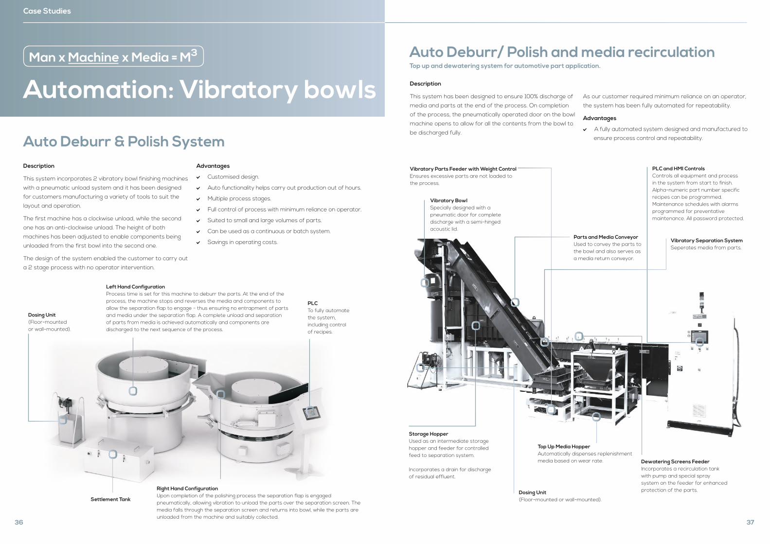
Automation: Vibratory bowls
Man x Machine x Media = M3
Case Studies
Description
This system incorporates 2 vibratory bowl finishing machines
with a pneumatic unload system and it has been designed
for customers manufacturing a variety of tools to suit the
layout and operation.
The first machine has a clockwise unload, while the second
one has an anti-clockwise unload. The height of both
machines has been adjusted to enable components being
unloaded from the first bowl into the second one.
The design of the system enabled the customer to carry out
a 2 stage process with no operator intervention.
Advantages
Customised design.
Auto functionality helps carry out production out of hours.
Multiple process stages.
Full control of process with minimum reliance on operator.
Suited to small and large volumes of parts.
Can be used as a continuous or batch system.
Savings in operating costs.
Auto Deburr & Polish System
Right Hand Configuration Upon completion of the polishing process the separation flap is engaged pneumatically, allowing vibration to unload the parts over the separation screen. The media falls through the separation screen and returns into bowl, while the parts are unloaded from the machine and suitably collected.
Dosing Unit (Floor-mountedor wall-mounted).
Settlement Tank
Left Hand Configuration Process time is set for this machine to deburr the parts. At the end of the process, the machine stops and reverses the media and components to allow the separation flap to engage - thus ensuring no entrapment of parts and media under the separation flap. A complete unload and separation of parts from media is achieved automatically and components are discharged to the next sequence of the process.
PLCTo fully automate the system, including control of recipes.
36
Description
This system has been designed to ensure 100% discharge of
media and parts at the end of the process. On completion
of the process, the pneumatically operated door on the bowl
machine opens to allow for all the contents from the bowl to
be discharged fully.
As our customer required minimum reliance on an operator,
the system has been fully automated for repeatability.
Advantages
A fully automated system designed and manufactured to
ensure process control and repeatability.
Auto Deburr/ Polish and media recirculation Top up and dewatering system for automotive part application.
Vibratory Bowl Specially designed with a pneumatic door for complete discharge with a semi-hinged acoustic lid.
Parts and Media Conveyor Used to convey the parts to the bowl and also serves as a media return conveyor.
Vibratory Parts Feeder with Weight Control Ensures excessive parts are not loaded to the process.
Top Up Media Hopper Automatically dispenses replenishment media based on wear rate.
Storage HopperUsed as an intermediate storage hopper and feeder for controlled feed to separation system.
Incorporates a drain for discharge of residual effluent.
Vibratory Separation System Seperates media from parts.
Dewatering Screens FeederIncorporates a recirculation tank with pump and special spray system on the feeder for enhanced protection of the parts.
PLC and HMI Controls Controls all equipment and process in the system from start to finish. Alpha-numeric part number specific recipes can be programmed. Maintenance schedules with alarms programmed for preventative maintenance. All password protected.
Dosing Unit (Floor-mounted or wall-mounted).
37
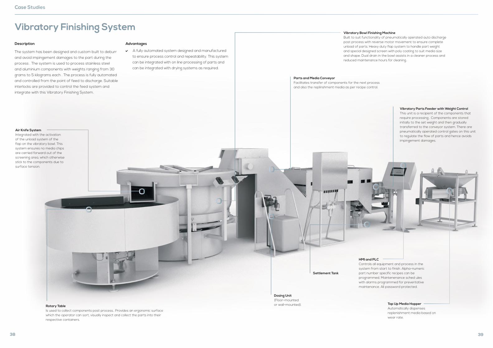
Description
The system has been designed and custom built to deburr
and avoid impingement damages to the part during the
process . The system is used to process stainless steel
and aluminium components with weights ranging from 30
grams to 5 kilograms each . The process is fully automated
and controlled from the point of feed to discharge. Suitable
interlocks are provided to control the feed system and
integrate with this Vibratory Finishing System.
Advantages
A fully automated system designed and manufactured
to ensure process control and repeatability. This system
can be integrated with on line processing of parts and
can be integrated with drying systems as required.
Vibratory Finishing System
Air Knife System Integrated with the activation of the unload system of the flap on the vibratory bowl. This system ensures no media chips are carried forward out of the screening area, which otherwise stick to the components due to surface tension.
Rotary Table Is used to collect components post process.. Provides an ergonomic surface which the operator can sort, visually inspect and collect the parts into their respective containers.
38
Case Studies
Vibratory Parts Feeder with Weight Control This unit is a recipient of the components that require processing . Components are stored initially to the set weight and then gradually transferred to the conveyor system. There are pneumatically operated control gates on this unit to regulate the flow of parts and hence avoids impingement damages.
Parts and Media Conveyor Facilitates transfer of components for the next process and also the replinshment media as per recipe control.
Vibratory Bowl Finishing Machine Built to suit functionality of pneumatically operated auto discharge post process with reverse motor movement to ensure complete unload of parts. Heavy duty flap system to handle part weight and special designed screen with poly coating to suit media size and shape. Dual drain in the bowl assists in a cleaner process and reduced maintenance hours for cleaning.
Settlement Tank
Top Up Media Hopper Automatically dispenses replenishment media based on wear rate.
HMI and PLC Controls all equipment and process in the system from start to finish. Alpha-numeric part number specific recipes can be programmed. Maintenenance sched ules with alarms programmed for preventative maintenance. All password protected.
Dosing Unit (Floor-mountedor wall-mounted).
39
Description
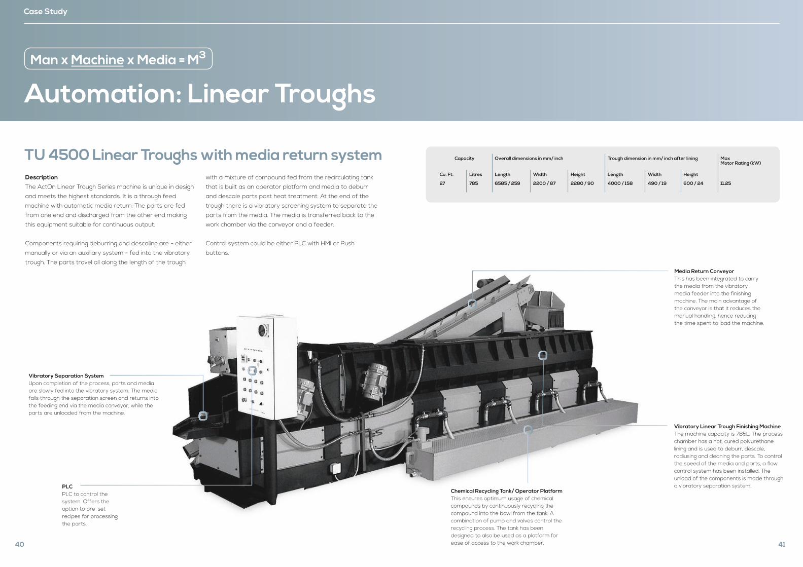
The ActOn Linear Trough Series machine is unique in design
and meets the highest standards. It is a through feed
machine with automatic media return. The parts are fed
from one end and discharged from the other end making
this equipment suitable for continuous output.
Components requiring deburring and descaling are - either
manually or via an auxiliary system - fed into the vibratory
trough. The parts travel all along the length of the trough
with a mixture of compound fed from the recirculating tank
that is built as an operator platform and media to deburr
and descale parts post heat treatment. At the end of the
trough there is a vibratory screening system to separate the
parts from the media. The media is transferred back to the
work chamber via the conveyor and a feeder.
Control system could be either PLC with HMI or Push
buttons.
Vibratory Separation System Upon completion of the process, parts and media are slowly fed into the vibratory system. The media falls through the separation screen and returns into the feeding end via the media conveyor, while the parts are unloaded from the machine.
PLCPLC to control the system. Offers the option to pre-set recipes for processing the parts.
Automation: Linear Troughs
Case Study
TU 4500 Linear Troughs with media return system
40
Man x Machine x Media = M3
Media Return Conveyor This has been integrated to carry the media from the vibratory media feeder into the finishing machine. The main advantage of the conveyor is that it reduces the manual handling, hence reducing the time spent to load the machine.
Vibratory Linear Trough Finishing MachineThe machine capacity is 785L. The process chamber has a hot, cured polyurethane lining and is used to deburr, descale, radiusing and cleaning the parts. To control the speed of the media and parts, a flow control system has been installed. The unload of the components is made through a vibratory separation system.
Chemical Recycling Tank/ Operator Platform This ensures optimum usage of chemicalcompounds by continuously recycling thecompound into the bowl from the tank. Acombination of pump and valves control therecycling process. The tank has been designed to also be used as a platform for ease of access to the work chamber. 41
Capacity Overall dimensions in mm/ inch Trough dimension in mm/ inch after lining Max Motor Rating (kW)
Cu. Ft. Litres Length Width Height Length Width Height
27 785 6585 / 259 2200 / 87 2280 / 90 4000 / 158 490 / 19 600 / 24 11.25
Automation: DryerMan x Machine x Media = M3
Case Study
Description
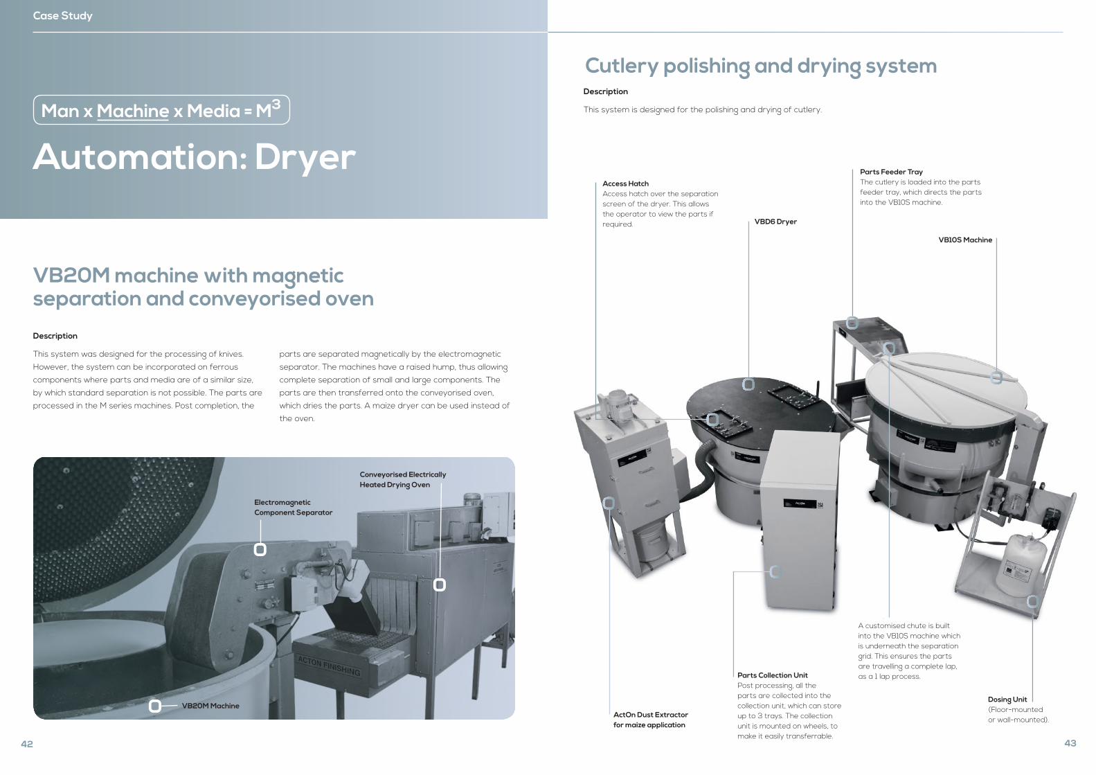
This system was designed for the processing of knives.
However, the system can be incorporated on ferrous
components where parts and media are of a similar size,
by which standard separation is not possible. The parts are
processed in the M series machines. Post completion, the
parts are separated magnetically by the electromagnetic
separator. The machines have a raised hump, thus allowing
complete separation of small and large components. The
parts are then transferred onto the conveyorised oven,
which dries the parts. A maize dryer can be used instead of
the oven.
VB20M machine with magnetic separation and conveyorised oven
Electromagnetic Component Separator
VB20M Machine
Conveyorised Electrically Heated Drying Oven
42
Description
This system is designed for the polishing and drying of cutlery.
Cutlery polishing and drying system
ActOn Dust Extractor for maize application
VBD6 Dryer
Dosing Unit (Floor-mountedor wall-mounted).
Access HatchAccess hatch over the separation screen of the dryer. This allows the operator to view the parts if required.
Parts Collection Unit Post processing, all the parts are collected into the collection unit, which can store up to 3 trays. The collection unit is mounted on wheels, to make it easily transferrable.
A customised chute is built into the VB10S machine which is underneath the separation grid. This ensures the parts are travelling a complete lap, as a 1 lap process.
Parts Feeder TrayThe cutlery is loaded into the parts feeder tray, which directs the parts into the VB10S machine.
43
VB10S Machine
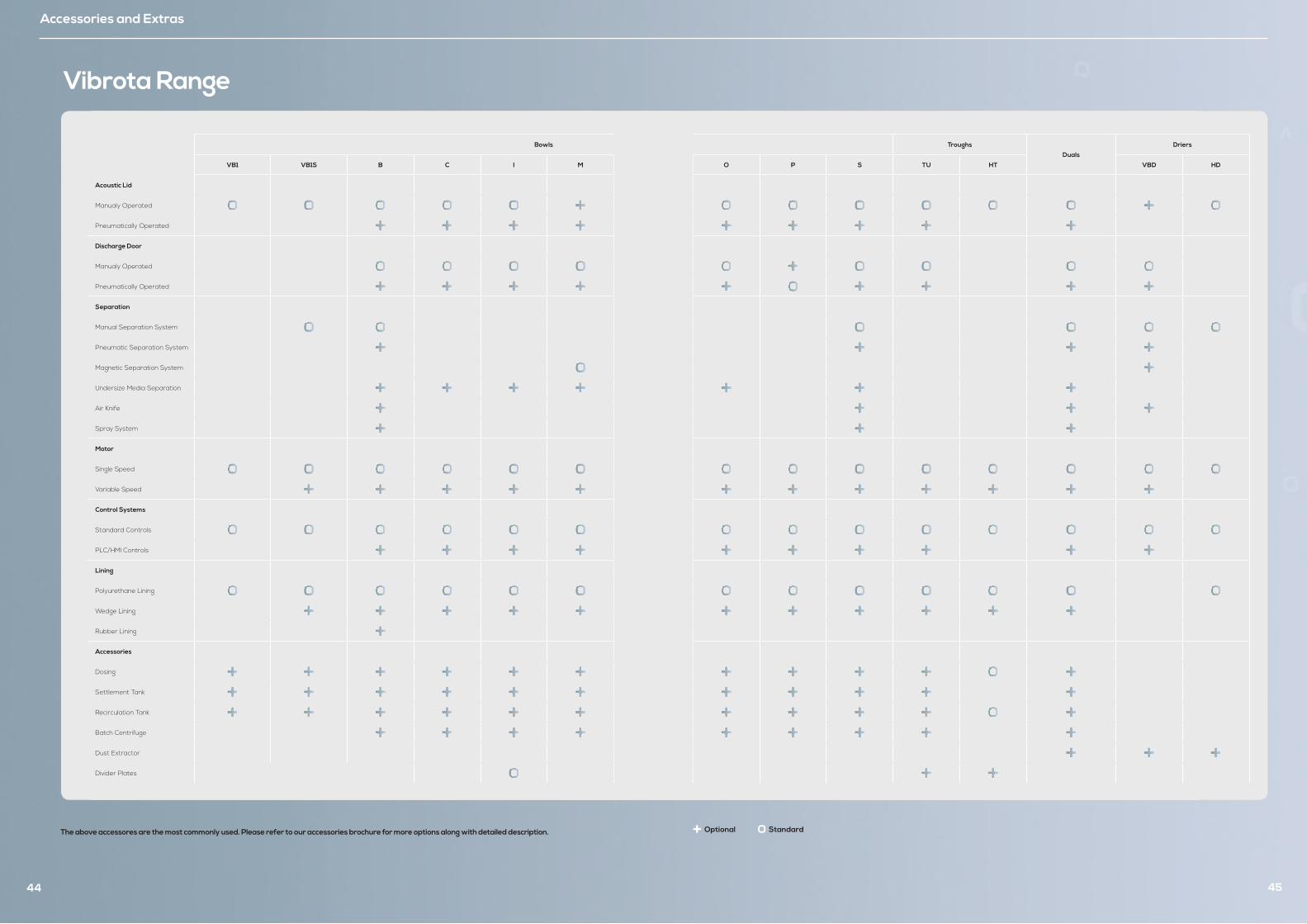
Bowls Troughs
Duals
Driers
VB1 VB1S B C I M O P S TU HT VBD HD
Acoustic Lid
Manualy Operated
Pneumatically Operated
Discharge Door
Manualy Operated
Pneumatically Operated
Separation
Manual Separation System
Pneumatic Separation System
Magnetic Separation System
Undersize Media Separation
Air Knife
Spray System
Motor
Single Speed
Variable Speed
Control Systems
Standard Controls
PLC/HMI Controls
Lining
Polyurethane Lining
Wedge Lining
Rubber Lining
Accessories
Dosing
Settlement Tank
Recirculation Tank
Batch Centrifuge
Dust Extractor
Divider Plates
Accessories and Extras
44
The above accessores are the most commonly used. Please refer to our accessories brochure for more options along with detailed description.
Vibrota Range
45
Optional Standard
10
Consumables
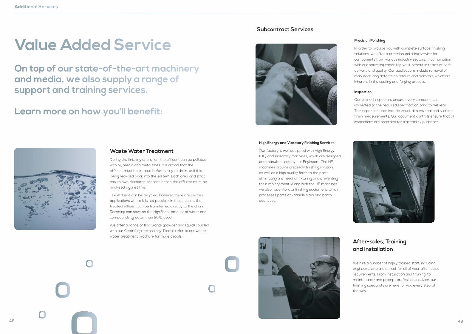
Waste Water TreatmentDuring the finishing operation, the effluent can be polluted
with oil, media and metal fines. It is critical that the
effluent must be treated before going to drain, or if it is
being recycled back into the system. Each area or district
has its own discharge consent, hence the effluent must be
analysed against this.
The effluent can be recycled, however there are certain
applications where it is not possible. In those cases, the
treated effluent can be transferred directly to the drain.
Recycling can save on the significant amount of water and
compounds (greater than 90%) used.
We offer a range of flocculants (powder and liquid) coupled
with our Centrifugal technology. Please refer to our waste
water treatment brochure for more details.
Value Added Service On top of our state-of-the-art machinery and media, we also supply a range of support and training services.
Learn more on how you’ll benefit:
Additional Services
48
After-sales, Training and Installation
We hire a number of highly trained staff, including
engineers, who are on-call for all of your after-sales
requirements. From installation and training, to
maintenance and prompt professional advice, our
finishing specialists are here for you every step of
the way.
Subcontract Services
Precision Polishing
In order to provide you with complete surface finishing
solutions, we offer a precision polishing service for
components from various industry sectors. In combination
with our barrelling capability, you’ll benefit in terms of cost,
delivery and quality. Our applications include removal of
manufacturing defects on femurs and aerofoils, which are
inherent in the casting and forging process.
Inspection
Our trained inspectors ensure every component is
inspected to the required specification prior to delivery.
The inspections can include visual, dimensional and surface
finish measurements. Our document controls ensure that all
inspections are recorded for traceability purposes.
High Energy and Vibratory Finishing Services
Our factory is well equipped with High Energy
(HE) and Vibratory machines, which are designed
and manufactured by our Engineers. The HE
machines provide a speedy finishing solution,
as well as a high quality finish to the parts,
eliminating any need of fixturing and preventing
their impingement. Along with the HE machines
we also have Vibrota finishing equipment, which
processes parts of variable sizes and batch
quantities.
49
What Our Customers Say
“ ActOn have revolutionised the way we finish, saving us time and money with the use of their machines and media. ”
“ From developing a bespoke process, to installing machines and training our staff, ActOn were excellent throughout. ”
“ I have been running this machine for over 10 years, and it’s still going.”
50
Quality you can see
51
Quality You Can SeeWe pride ourselves on our excellence, and over the years we have successfully demonstrated an ongoing compliance with ISO quality
and environmental standards.
For ISO, we currently hold:
We’re proud members of the ‘Made in Britain’ campaign.

ActOn Finishing Limited
213 Torrington Avenue
Tile Hill, Coventry, CV4 9HN, UK.
+44 (0) 24 7646 6914
www.acton-finishing.co.ukACT-36-VF
Issue 03
we redefine