Embed Size (px)
Citation preview
Vol. 127 (2015) ACTA PHYSICA POLONICA A No. 4
Proceedings of the 4th International Congress APMAS2014, April 24-27, 2014, Fethiye, Turkey
Wear Properties of TIG Surface Alloyed Steel with
50%Fe-10%W-40%B Alloy
E. Abakaya,*, B. Kilincb, S. Sena, U. Sena
aSakarya University Engineering Faculity, Department of Metallurgy
and Material Engineering, 54187, Serdivan Sakarya, TurkeybSakarya University, Ari�ye Vocational High School, 54580, Ari�ye Sakarya, Turkey
In the present study, AISI 1020 plain carbon steel was surface alloyed with preplaced 50%Fe-10%W-40%Balloying powders using a tungsten�inert gas (TIG) heat source. Microstructure, hardness, and wear resistance ofthe surface alloyed layer were investigated. Following the surface alloying, conventional characterization techniquessuch as optical microscopy (OM), scanning electron microscopy (SEM), energy dispersive X-ray spectroscopy(EDS), and X-ray di�raction analysis (XRD) were used to study the phase and microstructural examinations ofthe alloyed surfaces. Hardness measurements were performed across the alloyed zones, and wear properties ofthe alloyed surfaces were evaluated using a ball-on-disc wear test method. Hardness values of the phases formedin the alloyed layer are changing between 620±30 HV0.1 and 2095±254 HV0.1. The major phases formed in thesurface alloyed layer were Fe2B, FeB and FeW2B2. Wear test were realized against Alumina ball under the loadsof 2.5 N, 5 N and 10 N at the sliding speed of 0.1 m/s for 250 m sliding distance. The friction coe�cient of the50%Fe-10%W-40%B alloyed steel surface is changing between 0.70 and 0.79 depending on applied loads. The wearrates of the surface alloyed steel ranged from 4.01× 10⁻⁵ mm3/m to 4.14× 10⁻⁴ mm3/m.
DOI: 10.12693/APhysPolA.127.957
PACS: 81.20.Vj, 81.05.Bx, 81.40.Pq, 81.65.Lp
1. Introduction
Transition metal borides have numerous useful physi-cal and chemical characteristics that make them impor-tant materials to study. Prominent characteristics in-clude heat resistance, great hardness, wear resistance,and high-temperature electrical resistance. Tungstenborides are resistant to thermal shock and are good ther-mal conductors. They are used in high-temperature ap-plications such as crucibles and ingot molds for precisionmetallurgy [1, 2].Surface alloying is a commonly employed method to
improve surface properties of agricultural tools, compo-nents for mining operation, soil preparation equipmentsand others [3]. The surface alloying of steels, by addingthe powder of a desirable composition, is a process inwhich the alloy powder and a thin surface layer of thesubstrate material are simultaneously melted and rapidlysolidi�ed to form a dense coating metallurgically bondedwith the substrate. Various alloying elements such as;chromium, titanium, and tungsten may be introducedprior to or during the alloying of di�erent steel base ma-terials [4].High-energy density sources have widely applied hard
facing alloys such as electron beam, plasma arc andlaser [5�8]. Among the welding deposition techniques,tungsten inert gas arc (TIG or GTAW) welding is a verye�ective and techno-economical solution for wear applica-
*corresponding author; e-mail: [email protected]
tions. This process has following advantages: high depo-sition rate, high maneuverability, large-scale availability,low cost and compatibility with a wide range of materi-als [9]. TIG surface alloying associated with rapid heat-ing and cooling rate provided a unique opportunity forthe non-equilibrium synthesis of materials and producedrapidly solidi�ed �ne microstructures with extended solidsolution of alloying elements [10].In the present study, AISI 1020 plain carbon steel sur-
face was alloyed with preplaced 50%Fe-10%W-40%B al-loying powders using TIG welding. The main goal of thestudy was to characterize the structural and dry slidingwear friction properties of the surface alloyed low carbonsteels with 50%Fe-10%W-40%B.
2. Experimental
The substrate material for surface alloying treatmentwas prepared from AISI 1020 steel plates with the di-mensions of 20 mm×60 mm×5 mm. The nominal chem-ical composition of the AISI 1020 steel (in wt%) was asfollows: 0.17�0.38 % C, 0.18 % Si, 0.52 % Mn and Fe,the balance. Before the surface alloying treatment, thesespecimens were ground and cleaned with acetone to re-move any oxide and grease and then dried with com-pressed air. Commercial ferrotungsten, ferroboron andArmco iron powders were used for the surface alloyingtreatment. Ferrotungsten and ferroboron were groundedby ring grinder and sieved to be 45 µm particle sizes.Surface alloying powder mixture was prepared by usinga ball mill for 15 min at 120 RPM from the ground fer-rous boron and tungsten powders and iron (45 µm) to be50%Fe- 10%W-40%B. Prepared powders were placed on
(957)
958 E. Abakay et al.
the coated plate and pressed under the loads of 100 bar.Alloying powder placed on the steel plate was melted byTIG welding process. TIG welding parameters are de-tailed in Table I.
TABLE IExperimental parameters ofTIG surface alloying
Parameter Value
Electrode Type W-2 pct ThO
Diameter 2.4 mm
Angle 70 deg
Voltage 20 V
Current 110 A
Heat input 2.2 MJ/m
Protective gas Type Ar (%99.9 Ar)
Flow 12 L/min
Welding speed Travel speed 60 mm/min
Heat input Q = 60 x I xV/S, I: current,
V: voltage, S: travel speed [11]
Fig. 1. SEM micrographs of surface alloyed AISI 1020steel.
The phase analysis was realized using a RigakuXRD/D/MAX/2200/PC X-ray di�ractometer withCu Kα to analyze the constituent phases in the surfacealloyed layer. Metallographic examinations on themetallographically prepared and etched samples with3% nital for 10 s were realized from the cross-section
of the surface alloyed layer using by Nikon Epiphot200 optical microscopy (OM) and JEOL JSM - 6060scanning electron microscopy (SEM). The hardness ofthe phases formed in the alloyed layer and transitionzone and matrix were measured from the cross-sectionby Future-Tech FM 700 micro-hardness tester.Wear and friction tests of the surface alloyed steels
were evaluated using a ball-on-disc tribometer in the at-mospheric condition (62% relative humidity). The sam-ples with 20 mm×20 mm×5 mm were cut from as re-ceived TIG melted 50%Fe-10%W-40%B alloy on the steelsubstrates and were ground by 1200 grit silicon carbidepapers for obtain a smooth surface. The sliding speedwas 0.1 m/s; the applied loads were 2.5 N, 5 N and 10 Nand the sliding distance was 250 m. Mean Hertzian con-tact pressures [12] calculated for alumina ball under theloads of 2.5 N, 5 N and 10 N are 390 N/mm2, 490 N/mm2
and 620 N/mm2, respectively. The frictional force, mon-itored by a load cell attached to the ball holder, wasrecorded continuously. Wear rate was measured primar-ily by volumetric (volume loss) means. To evaluate wearresistance, the wear volume was calculated from the worncross-sectional area of the surface alloyed plate which wasmeasured by KMA P6 optical pro�lometer.
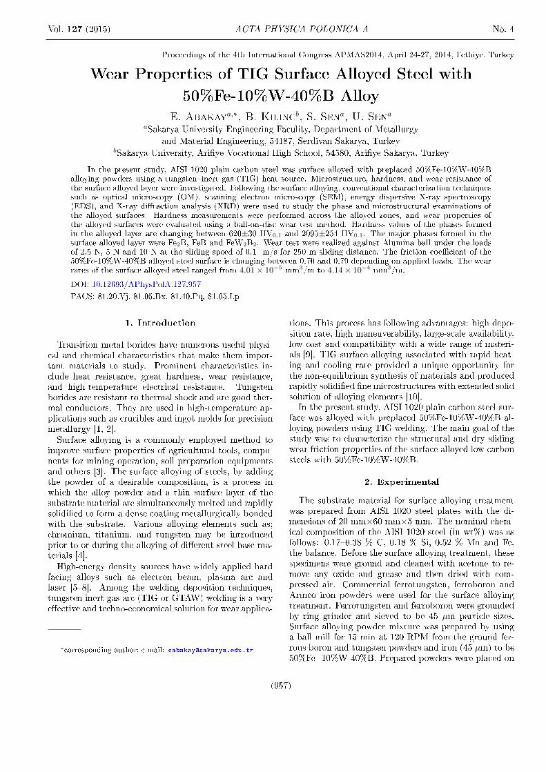
Fig. 2. X-ray spectrum of surface alloyed layer on AISI1020 steel.
3. Results and discussion
Surface alloying process was applied on AISI 1020 steelsubstrates. The treatment was realized by ferrotungsten,ferroboron and Armco iron as �ller alloys as to be 50%Fe-10%W-40%B. The composition of the �ller alloy mixturesof ferrotungsten, ferroboron and iron powders were cal-culated and used for the production of Fe2B, FeB andFeW2B2 major phases in the �nal produced alloy accord-ing to Fe-W-B phase diagram [13]. As known, the boridesof iron and FeW2B2 phases have very high hardness, wearresistance and corrosion resistance [13�15]. In the pro-cess, prepared powder mixture was melted on the steelsamples and simultaneously rapidly solidi�ed to form adense coating bonded on the base metal.

Wear Properties of TIG Surface Alloyed Steel with 50%Fe-10%W-40%B Alloy. . . 959
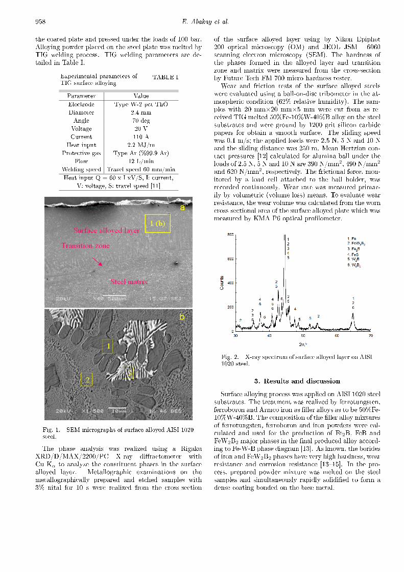
Fig. 3. (a) Friction coe�cient and (b) wear rate vari-ation of surface alloyed.
Figure 1a shows the lateral section of the surface al-loyed steel. The �gure shows that surface alloyed steelsamples include three distinct regions which are: i) sur-face alloyed layer which includes Fe, B and W, ii) transi-tion zone and iii) steel matrix. According to Fig. 1a, sur-face alloyed layer gave a smooth rippled surface topogra-phy and was found to be free from gas porosity and cracksin general. Figure 1b show the surface alloyed layer mi-crostructure. As shown from the �gure that solidi�catedmicrostructure includes primary dendrites of the Fe-Wsolid solution (marked as 1 on the micrograph), eutecticmicrostructures of Fe+Fe2B (marked as 2 on the micro-graph) and FeW2B2+Fe eutectic (marked as 3 on themicrograph) which were investigated by EDS analysis.
Figure 2 shows the XRD analysis of surface alloyedAISI 1020 steel with 50%Fe- 10%W-40%B alloy. Theanalysis showed that the layer includes Fe2B, FeB andFeW2B2 phases as major and W2B and W2B5 phases astrace [13].
In the alloying treatments, solidi�cation of the meltedzones is too speed and it is possible that the formation ofsome deal phases of the used elements can be realized be-cause of su�cient time for the production of stable phasestook place in the phase diagram of the Fe-W-B [13].
Fig. 4. SEM micrographs of the worn surfaces of thesurface alloyed AISI 1020 steel with 50%FE-10%W-40%B, alloys for (A) 2.5N, (B) 5N and (C) 10N load.
Figure 3a shows the variation of friction coe�cients asa function of applied load against alumina ball at thesliding speed of 0.1 m/s for 250 m sliding distance. Itseems from this �gure that increases in applied load donot caused to change of friction coe�cient, e�ectively.Figure 3b presents the wear rate of the surface alloyed
AISI 1020 steel against alumina ball. As shown from the�gure that increase in applied load caused to increase of

960 E. Abakay et al.
wear rate for all loads. Archard's equation shows thatincreasing load reasoned the increase of wear rate [16].The load is e�ective parameters in the wear test which iscaused to increase of wear rate. Increase in applied load100% caused to increase in wear rate of 446% increase inapplied load 300% caused to increase of 932%.AISI 1020 steel with increased loads, respectively.Figures 4b and 4c show the wear tracks of surface al-
loyed AISI 1020 steel under the loads of 2.5 N, 5 N and10 N, respectively. SEM images and EDS analysis showedthat oxidative wear products realized on the wear trackand abrasive micro abrasive wear scratches. Wear of thesurface alloyed layer is largely oxidative in nature under2.5 N and 5 N. Increasing of applied load, changed wearmechanism from oxidative to abrasive for 10 N loads.
4. Conclusions
1. Surface alloying process was applied on AISI 1020steel substrates by TIG welding.
2. Surface alloyed layers of the steel consist of Fe2B,FeB and FeW2B2 phases.
3. The surface alloyed steel samples include three dis-tinct regions which are surface alloyed layer whichincludes Fe, B and W, transition zone and steelmatrix.
4. The surface alloyed layer includes primary den-drites of the Fe-W solid solution, eutectic mi-crostructures of Fe+Fe2B and FeW2B2+Fe eutec-tic.
5. XRD analysis of surface alloyed AISI 1020 steelshowed that the layer includes Fe2B, FeB andFeW2B2 phases as major and W2B and W2B5
phases as trace.
6. The friction coe�cient is close for 2.5 N and 5 Napplied loads (0.77�0.79) and with increasing of theload from 5 N to 10 N, the friction coe�cient de-creased from 0.79 to 0.70.
7. Increase in applied load caused to increase of wearrate.
8. Wear mechanism of the surface alloyed AISI 1020steel is for 2.5 N and 5 N loads oxidative and for 10N oxidative and abrasive.
References
[1] S. Stadler, R.P. Winarski, J.M. MacLaren, D.L. Ed-erer, J. vanEk, A. Moewes, M.M. Grush, T.A. Call-cott, R.C.C. Perera, Journal of Electron Spectroscopyand Related Phenomena 110, 75 (2000).
[2] M. Usta, I. Ozbek, M. Ipek, C. Bindal, A.H. Ucisik,Surface and Coatings Technology 194, 330 (2005).
[3] M.F. Buchely, J.C. Gutierrez, L.M. León, A. Toro,Wear 259, 52 (2005).
[4] S.M.H. Hojjatzadeh, A. Halvaee, M. Hey-darzadeh Sohi, Journal of Materials ProcessingTechnology 212, 2496 (2012).
[5] V. Balasubramanian, R. Varahamoorthy, C.S. Ra-machandran, C. Muralidharan, The InternationalJournal of Advanced Manufacturing Technology 40,887 (2009).
[6] J.C. Oh, S. Lee, Surface and Coatings Technology179, 340 (2004).
[7] A. d'Oliveira, R.S.C. Paredes and R.L.C. Santos,Journal of Materials Processing 171, 167 (2006).
[8] P.W. Leech, Materials and Design 54, 539 (2013).
[9] R.A. Jeshvaghani, M. Jaberzadeh, H. Zohdi, M. Sha-manian, Materials and Design 54, 491 (2013).
[10] D. Deng, Y. Zhou, T. Bi, X. Liu, Materials and De-sign 52, 720 (2013).
[11] S. Buytoz, Surface and Coatings Technology 200,3734 (2006).
[12] B. Stingl, M. Ciavarella, N. Ho�mann, InternationalJournal of Mechanical Sciences 72, 55 (2013).
[13] V. Raghavan, Journal of Phase Equilibria 24, 457(2003).
[14] O. Ozdemir, M. Usta, C. Bindal and A.H. Ucisik,Vacuum 80, 1391 (2006).
[15] I. Campos, M. Palomar, A. Amador, R. Ganem andJ. Martinez, Surface and Coatings Technology 201,2438 (2006).