Embed Size (px)
Citation preview

Feb. 4 – 8, 2013 2013 Gas-Lift Workshop
36th Gas-Lift Workshop Stavanger, Norway February 4 – 8, 2013
Weatherford
Inverse Gas Lift System (IGLS)
Jerry Sutton – Senior Applications Engineer

Feb. 4 – 8, 2013 2013 Gas-Lift Workshop 2
Contents
• Why is IGLS needed?
• What is IGLS?
• Components of the IGLS System
• Summary of Benefits

Feb. 4 – 8, 2013 2013 Gas-Lift Workshop 3
Why is IGLS needed?
• Many wells are now reaching the stage that they may require to be
gas lifted.
• These wells may not be designed to allow conventional gas lift
systems.
• Workover cost may prevent traditional gas lift system installation
• Annulus integrity may also be compromised preventing gas
injection.
• Full depth gas injection may be required.

Feb. 4 – 8, 2013 2013 Gas-Lift Workshop 4
What is IGLS?
• IGLS allows a method of gas injection via an insert string with no
reliance on well annuli.
• Injection through new insert bore.
• Production via annular spaces & bores of the IGLS components.
• Installed using traditional intervention techniques thereby
minimising topside disruption.
• Utilises existing tree.
• Fully removable with no effect on original completion components.

Feb. 4 – 8, 2013 2013 Gas-Lift Workshop 5
IGLS System
• The IGLS components consist of the following (bottom to top):
– Gas injection valve at depth (customer specific), with coiled
tubing to dual flow safety valve.
– Dual flow safety valve installed in the existing safety valve
profile, locked in place using a suspension hanger.
– Seal stinger and tubing to intermediate spool and concentric
hanger at surface.

Feb. 4 – 8, 2013 2013 Gas-Lift Workshop 6
Components
• Dual Flow Safety Valve (DFSV)
– API 14A, Class 1, qualified, rod piston design.
– Controlled via existing DHSV control line.
– Two flow paths, Gas through centre bore & Production through
annular bores.
– Flapper closes off both Injection & Production giving full well
control.
– Metal / Metal sealing of flapper & flow tube nose seal.

Feb. 4 – 8, 2013 2013 Gas-Lift Workshop 7
Components
• Dual Flow Safety Valve (DFSV) - Flapper in closed position.

Feb. 4 – 8, 2013 2013 Gas-Lift Workshop 8
Components
• Dual Flow Safety Valve (DFSV) - Flapper in open position.
Feb. 4 – 8, 2013 2013 Gas-Lift Workshop 9
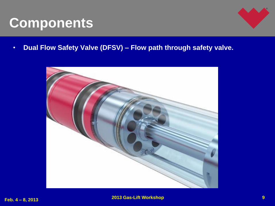
Components
• Dual Flow Safety Valve (DFSV) – Flow path through safety valve.

Feb. 4 – 8, 2013 2013 Gas-Lift Workshop 10
Components
• Dual Flow Safety Valve (DFSV).

Components
• Dual Flow Safety Valve Sizes:
– 4-1/2 x 3.813
– 5-1/2 x 4.313
– 5-1/2 x 4.562
– 7 x 5.750 – Statoil 3 Stage System
– 7 x 5.950
• Dual Flow Safety Valve Seals:
– Standard Chevron Stack.
– Weatherford Damaged Bore (certain sizes).
– Swellable Stack (certain sizes).
Feb. 4 – 8. 2013 2013 Gas-Lift Workshop
11

Feb. 4 – 8, 2013 2013 Gas-Lift Workshop 12
Components
• Suspension Hanger
– Carries full string weight, minimises load on DFSV no-go.
– Gas Injection through bore.
– Production via annular space past slips.
– PBR or Latching Seal Bore for connection to upper components.

Feb. 4 – 8, 2013 2013 Gas-Lift Workshop 13
Components
• Seal Stinger
– Used for connection to upper completion & surface equipment.
– Seal Stinger mates with PBR on suspension hanger.
– Shearable centraliser gives positive indication of mate.
– Sealing within the PBR has been verified under a simulated
dynamic 20 year temperature, pressure & movement life cycle.

Feb. 4 – 8, 2013 2013 Gas-Lift Workshop 14
Components
• Intermediate Spool
– Normally supplied by well head supplier.
– No modification to xmas tree required.
– ID dependant on existing tree and hanger
(Client specific requirements).
• Concentric Hanger
– No-go within intermediate spool.
– Lock-down & self locking systems.
– Gas injection & production bores.
– Run with standard industry tools.

Feb. 4 – 8, 2013 2013 Gas-Lift Workshop 15
Summary Statements
• Means of introducing gas lift to a well which has no gas lift
capability or a well which has casing integrity problems.
• Utilizes existing tree & completion.
• DFSV isolates both production and injection flow paths providing
full well control.
• DFSV utilises existing safety valve seal bores for control.
• Current sizes of DFSV Qualified to API 14A 11th Edition Class 1.
• Installed using intervention techniques, saving rig time and costs.
• No reliance on the DHSV no-go.
• Removable with no effect on existing completion or well integrity.
• Full well depth gas injection possible.

Thank You & Questions
Feb. 4 – 8. 2013 2013 Gas-Lift Workshop
16

Feb. 4 – 8, 2013 2013 Gas-Lift Workshop 17
Copyright
Rights to this presentation are owned by the company(ies) and/or author(s) listed on the title page. By submitting this presentation to the Gas-Lift Workshop, they grant to the Workshop, the Artificial Lift Research and Development Council (ALRDC), and the American Society of Mechanical Engineers (ASME), rights to:
– Display the presentation at the Workshop.
– Place it on the www.alrdc.com web site, with access to the site to be as directed by the Workshop Steering Committee.
– Place it on a CD for distribution and/or sale as directed by the Workshop Steering Committee.
Other uses of this presentation are prohibited without the expressed written permission of the company(ies) and/or author(s) who own it and the Workshop Steering Committee.

Feb. 4 – 8, 2013 2013 Gas-Lift Workshop 18
Disclaimer
The following disclaimer shall be included as the last page of a Technical Presentation or Continuing Education Course. A similar disclaimer is included on the front page of the Gas-Lift Workshop Web Site.
The Artificial Lift Research and Development Council and its officers and trustees, and the Gas-Lift Workshop Steering Committee members, and their supporting organizations and companies (here-in-after referred to as the Sponsoring Organizations), and the author(s) of this Technical Presentation or Continuing Education Training Course and their company(ies), provide this presentation and/or training material at the Gas-Lift Workshop "as is" without any warranty of any kind, express or implied, as to the accuracy of the information or the products or services referred to by any presenter (in so far as such warranties may be excluded under any relevant law) and these members and their companies will not be liable for unlawful actions and any losses or damage that may result from use of any presentation as a consequence of any inaccuracies in, or any omission from, the information which therein may be contained.
The views, opinions, and conclusions expressed in these presentations and/or training materials are those of the author and not necessarily those of the Sponsoring Organizations. The author is solely responsible for the content of the materials.
The Sponsoring Organizations cannot and do not warrant the accuracy of these documents beyond the source documents, although we do make every attempt to work from authoritative sources. The Sponsoring Organizations provide these presentations and/or training materials as a service. The Sponsoring Organizations make no representations or warranties, express or implied, with respect to the presentations and/or training materials, or any part thereof, including any warrantees of title, non-infringement of copyright or patent rights of others, merchantability, or fitness or suitability for any purpose.