Embed Size (px)
Citation preview

Instructor Giullio Jacucci, Petri Savolainen
Web-based indoor positioning system using QR-codes as mark-ers
Zhen Shi
Helsinki November 5, 2020
Master of Computer Science
UNIVERSITY OF HELSINKIDepartment of Computer Science
Faculty of Science Department of Computer Science
Zhen Shi
Web-based indoor positioning system using QR-codes as markers
Computer Science
Master of Computer Science November 5, 2020 40 pages + 0 appendix pages
QR code, Augment Reality, indoor position
Location tracking has been quite an important tool in our daily life. The outdoor location trackingcan easily be supported by GPS. However, the technology of tracking smart device users indoorposition is not at the same maturity level as outdoor tracking.
AR technology could enable the tracking on users indoor location by scanning the AR marker withtheir smart devices. However, due to several limitations (capacity, error tolerance, etc.) AR markersare not widely adopted. Therefore, not serving as a good candidate to be a tracking marker. Thispaper carries out a research question whether QR code can replace the AR marker as thetracking marker to detect smart devices’ user indoor position.
The paper has discussed the research question by researching the background of the QR code andAR technology. According to the research, QR code should be a suitable choice to implement asa tracking marker. Comparing to the AR marker, QR code has a better capacity, higher errortolerance, and widely adopted. Moreover, a web application has also been implemented as anexperiment to support the research question. It utilized QR code as a tracking marker for ARtechnology which built a 3D model on the QR code. Hence, the position of the user can beestimated from the 3D model.
This paper discusses the experiment result by comparing a pre-fixed target user’s position andreal experiment position with three different QR code samples. The limitation of the experimentand improvement ideas have also been discussed in this paper. According to the experiment, theresearch question has being answered that a combination of QR code and AR technologycould deliver a satisfying indoor location result in a smart device user.
Tiedekunta — Fakultet — Faculty Laitos — Institution — Department
Tekijä — Författare — Author
Työn nimi — Arbetets titel — Title
Oppiaine — Läroämne — Subject
Työn laji — Arbetets art — Level Aika — Datum — Month and year Sivumäärä — Sidoantal — Number of pages
Tiivistelmä — Referat — Abstract
Avainsanat — Nyckelord — Keywords
Säilytyspaikka — Förvaringsställe — Where deposited
Muita tietoja — övriga uppgifter — Additional information
HELSINGIN YLIOPISTO — HELSINGFORS UNIVERSITET — UNIVERSITY OF HELSINKI

ii
Contents
1 Introduction 1
1.1 Research Questions . . . . . . . . . . . . . . . . . . . . . . . . . . . . 1
1.2 Approach . . . . . . . . . . . . . . . . . . . . . . . . . . . . . . . . . 3
2 Background 5
2.1 Augmented Reality . . . . . . . . . . . . . . . . . . . . . . . . . . . . 5
2.1.1 History of Augmented Reality . . . . . . . . . . . . . . . . . . 5
2.1.2 AR Marker system . . . . . . . . . . . . . . . . . . . . . . . . 6
2.1.3 Computer Vision Methods in AR . . . . . . . . . . . . . . . . 7
2.1.4 AR Application . . . . . . . . . . . . . . . . . . . . . . . . . . 8
2.2 QR code . . . . . . . . . . . . . . . . . . . . . . . . . . . . . . . . . . 9
2.2.1 QR code system . . . . . . . . . . . . . . . . . . . . . . . . . . 10
2.3 Related Works . . . . . . . . . . . . . . . . . . . . . . . . . . . . . . . 14
3 Project and Experiments 16
3.1 Introduction of the experiments . . . . . . . . . . . . . . . . . . . . . 16
3.2 Implementation . . . . . . . . . . . . . . . . . . . . . . . . . . . . . . 17
3.2.1 Detect QR code from video stream . . . . . . . . . . . . . . . 17
3.2.2 Pose estimation . . . . . . . . . . . . . . . . . . . . . . . . . . 27
3.3 Demonstrate and result in analysis . . . . . . . . . . . . . . . . . . . 32
3.3.1 Demonstrate . . . . . . . . . . . . . . . . . . . . . . . . . . . . 32
3.3.2 Result analysis . . . . . . . . . . . . . . . . . . . . . . . . . . 33
4 Conclusion 38
References 39
1
1 Introduction
Technology brings a lot of convenience to people nowadays. Compared to decadesago, if one wishes to track the status of a post parcel. The most efficient way wasto make a phone call or send an email to the post office to get updates. Also thetransition information of the parcel may still be unclear or inaccurate. Nowadaysthere are various ways to track a parcel. People can easily go to the website to inputthe tracking number or scan the QR code provided on the post receipt without a needto type anything manually. At the present time, QR code starts to play a significantrole in people’s daily life, since it can hold up to 7089 characters compared with abarcode in which the maximum capacity is limited to only 20 digits. In addition tothe fact, the QR code does not require a certain angle to scan. It is a positioning-freecode [1].
Through recent years, QR code has been widely studied and applied in our daily life.The successful recognition rate has been stabilized which is powered by algorithmsthat perform well. However, its actual application has been commonly limited toprintouts on packages or documents which require certain graphical sampling andprocessing terminals at the other end, namely smartphones.
As we believe QR code brings people a new way of getting and tracking relevantinformation, we have also seen Augmented Reality(AR) have brought innovativeinteraction to the next level. Augment Reality is able to bring virtual informationto people’s immediate surroundings in a simple way. It increases people’s interactionwith virtual information in another dimension. AR aims to combine both the virtualenvironment and real-world objects while providing interactions to users[2]. Lookingforward to the near future where AR is much more common in our daily life, it mayassist many applications that were not feasible or easily implementable in the past.
This paper will discuss both QR code and AR technology in detail respectively inthe following chapters. In addition, a project combining QR code and AR methodwill also be presented to convey the point that QR code can be used for locationpurposes in a 3-dimensional space. The aim of the project is to take the key benefitsfrom both technologies, which meant to be used, and create a pose detection appbased on QR code, thus giving alternative choices to certain application fields.
1.1 Research Questions
Location and navigation have been extremely helpful in our daily life. It is quiteaffordable and intuitive as the function is enabled with any electronic devices withGPS or similar alternative sensors. Unfortunately, this is only limited to outdoorconditions as satellite signals are either in-reachable or too weak to be picked upand utilized meaningfully inside the building. Once the user is located indoors, amore common way to locate and giving navigation instructions would frequentlyrely on pre-deployed appliances, commonly BlueTooth beacons. This may introducevarious limitations as the service is solely depending on such hardware deployment
2
presence, service quality which can be significantly plunged due to massive simul-taneous connection requests and relative signal transmission distance. Hence, acontrast to such a centralized layout request. A distributed system that can operateindependently is preferred, Augmented Reality (AR) may compensate for the needsin such a situation.
AR provides opportunities for users to involve artificial objects and effects in theirphysical environment. This can be done through different solutions including ARmarker-based, markerless-based, GPS-based, etc. GPS-based is constrained signif-icantly due to the limitations mentioned above. Markerless based solutions aretargeted for providing generic information and are only applicable within a cer-tain context, indoor location is making less sense to be one use markerless basedsolution[3]. Therefore the marker-based solution is the most suitable candidate forthis specific application.
Typical AR markers have few limitations to support such indoor location applica-tions. AR marker usually contains merely 36 binary information which is a quitelimited amount. This can reduce its fault tolerance and reliability considerably.Inadvertent damage or missing any proportion of the marker is deemed to be apotential disruption of its normal function[4]. Moreover, the AR marker has lowtolerance on the scanning device’s camera pointing angle. A slight move away ofthe camera may result in AR function interruption thus requires a new scan. As amatter of fact, the AR marker may not function properly in a strong light reflectioncondition which introduces more constraints to its application scenario.
QR code, on the other hand is relatively more advanced in terms of maturity dueto the wide range of studies and applications. Information capacity is consideredto be exponentially increased in contrast to the AR marker. Therefore, a damageto the marker which equals to the size of 36 binaries will not be adequate to fullydisrupt the markers functionality. Even though the damage is hard to quantify insuch a way. Additionally, the QR code has multiple algorithms to restore its keyinformation in the distortion of its shape. If case QR code can be applied similarlyas an AR marker in an AR system, it could potentially benefit a decent leap fromboth the performance and reliability aspects.
Smartphones are common daily devices that nearly everyone holds. Moreover, suchdevices are matured technologically, and considered as appropriate carriers of ARalgorithms. Therefore the search question of this paper will be whether QR codecan be the replacement of AR-tag cooperate within AR technology todetect the indoor location and position of a smart devices’ user. Thereforeprove that a combination of these two elements can form a decent candidate inserving indoor location applications. The paper will also discuss the result of thequestion from position accurate point of view by comparing a fixed expect positionand a real detected position.

3
1.2 Approach
As discussed in the previous section (Research Questions), we would like to figureout a way to detect smart devices users’ indoor locations which takes both benefitsfrom QR code and AR technology. Eventually, smart devices users could use theirsmart devices to scan a detection marker and get the current location show on thesmart devices.
The project decided to use QR (Quick Response) code as the detection marker,compared with AR markers. QR code has several benefits that could be utilizedin the project. First of all, the QR code is quite common nowadays and has beenalready widely used on many occasions. Secondly, compared with AR code, it has alarger capacity and faster readability [3]. The AR mark usually consists of a 6*6 gridof white and black cells which are only able to store 36 binary symbols [4]. However,the capacity of QR code is much larger, it is able to encode 7089 numeric data or4926 alphanumeric data. Moreover, the most important reason for selecting a QRcode as detection marks, which has better error tolerance. It will be more suitablefor the project. Users usually need to scan the QR code from different angles andlocations, even though some part of the QR code is destructed or deformed, the QRcode still able to be detected successfully [5]. For those reasons, the QR code wouldbe the better choice for this project to use as detection markers.
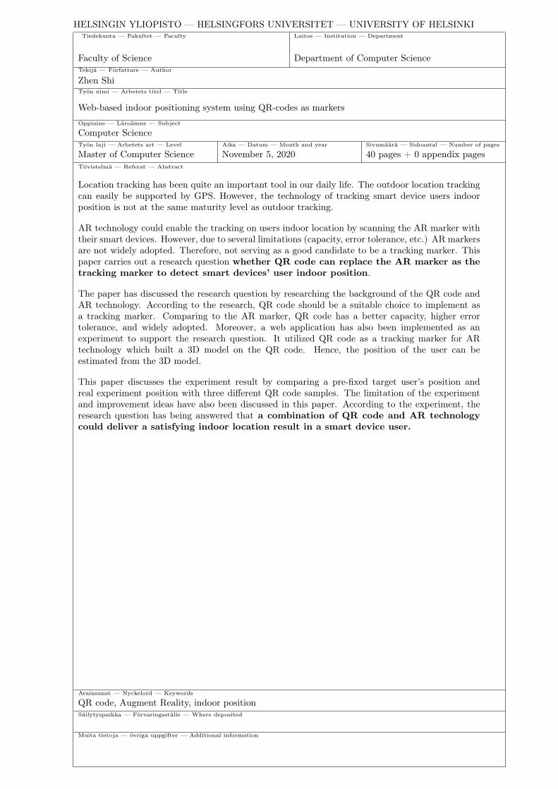
Figure 1: 3D model between device and QR code
After scanning the QR code, we will use AR technology to build 3D coordinationon the target QR code and get the location information back to the user’s device.First, we will find the targeting position pattern on the QR code and build the 3D
4
coordination on each point. After that, POIST will be used to build the 3D positionmodel between the QR code and the user’s smart devices as the graph shows 1.2.POIST is an algorithm that is usually used in AR technology to build the 3D modelon target marks [6]. It will estimate the scanning angle and distance between theusers’ devices and QR code. After that, we can send all location information backto users’ devices in real-time.
By the above approach, the project would utilize QR code in an AR environment.QR could make the whole system more stable and deliver more data. AR technologycould build the 3D model on the QR so that it could get the location information.This approach could solve AR marker’s limitation we discussed in the previoussection.

5
2 Background
2.1 Augmented Reality
The definition of Augmented Reality(AR) consists of three important characters.First of all, it should combine real and virtual information together to help peopleto do things better. It also can help conduct some task which people never did beforedue to the technical limitation. Secondly, it should be able to process interactionsbetween people, the physical world, and visual objects in real-time, which differsfrom traditional man-to-machine interactions that left the physical world outside.Finally, it should be registered in the 3D world [5].
A well-functioning AR system targets blend digital data into this physical worldwhich provides end-users the integration of immersive sensations, bring various vir-tual information (e.g. video stream, object info, etc.) to the users surroundingsand indirect view of the environment, it would eases their life and activate theirinteractions with the physical environment at multiple aspects [7].
Since AR does not fully immerse users into the synthetic environment, it is consid-ered an iconic difference from Virtual Reality (VR). In fact, some believe augmentedreality does not limit to the visual sense. Additionally other senses as well as hear-ing, touch, smell, all could be potentially augmented, even substitute each other[7]. Hearing-impaired could benefit from virtual objects notifications, while visuallyimpaired could be augmented in a similar substitution.
2.1.1 History of Augmented Reality
The emergence of such a system in recent years can be traced back to the early1990s. Virtual fixture, as widely believed as a pioneering platform that later con-ceived Virtual Reality (VR) and Augmented Reality (AR) was first developed atthe Armstrong Laboratory that belongs to the U.S. Air Force in 1992 [8]. However,AR technology was more or less a variation of VR, which was a concept being pur-posed as early as in the 50s by a cinematographer, Morton Heilig he developed thefirst prototype in 1962 and named it ’Sensorama’ [9], followed by a head-mounteddisplay invention by Ivan Sutherland in 1966. Two years later Sutherland advancedthis invention with a see-through display [7].
Commercial AR was introduced to the gaming industry and entertainment. AR-Quake, as the first outdoor AR game was developed by Bruce Thomas in 2000 [7].Followed by various AR applications in education, communications, and medicinesectors in 2008 and 2007 respectively [7]. By using marker-less AR techniques, ARwas applied in classrooms in late 2015 [10].
6
2.1.2 AR Marker system
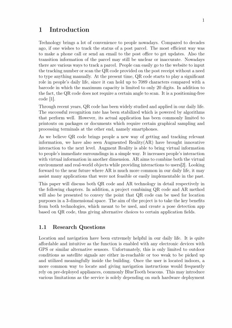
Marker-based AR There are two different types of AR: marker-based AR andmaker-less one. Marker-based AR requires the physical deployment of unique mark-ers in the reality environment[5]. The unique marker will be a fiducial marker thatconsists of patterns that make it possible to detected from digital camera imagesby an accompanying detection algorithm [11]. The result of augmenting virtual ob-jects will be delivered in the video frames. This will bring many benefits to robotnavigation and applications required a certain pose between camera and objects.
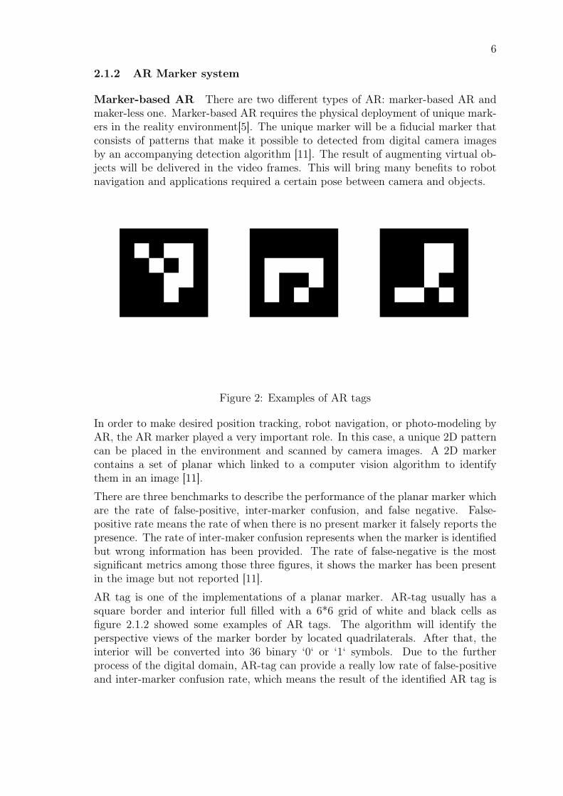
Figure 2: Examples of AR tags
In order to make desired position tracking, robot navigation, or photo-modeling byAR, the AR marker played a very important role. In this case, a unique 2D patterncan be placed in the environment and scanned by camera images. A 2D markercontains a set of planar which linked to a computer vision algorithm to identifythem in an image [11].
There are three benchmarks to describe the performance of the planar marker whichare the rate of false-positive, inter-marker confusion, and false negative. False-positive rate means the rate of when there is no present marker it falsely reports thepresence. The rate of inter-maker confusion represents when the marker is identifiedbut wrong information has been provided. The rate of false-negative is the mostsignificant metrics among those three figures, it shows the marker has been presentin the image but not reported [11].
AR tag is one of the implementations of a planar marker. AR-tag usually has asquare border and interior full filled with a 6*6 grid of white and black cells asfigure 2.1.2 showed some examples of AR tags. The algorithm will identify theperspective views of the marker border by located quadrilaterals. After that, theinterior will be converted into 36 binary ‘0‘ or ‘1‘ symbols. Due to the furtherprocess of the digital domain, AR-tag can provide a really low rate of false-positiveand inter-marker confusion rate, which means the result of the identified AR tag is
7
very reliable. The false probability can be reached to under 0.0039 percentage [11].
Marker-less AR Marker-less AR, also known as instant tracking, is a techniqueused to track the physical environment via merging inputs from different sensorsand computer vision. By marker-less AR tracking the augment objective can bedelivered without any physical markers[12].
Within the development of the marker-less AR technique, four following componentsare paramount. Natural feature detector (e.g. corner, line, points, structure, etc.),reference image keypoint identification descriptor, matcher for descriptors of thereference image and pre-stored database image, and pose estimation on cameraorientation and position[13].
Descriptors are generally divided into vector-based and binary-based categories.For a real-time application, as what AR required for, binary descriptor becamemore practical since vector descriptors are too expensive at computation althoughstrengthen at high description rate [14].
Pose estimation could be challenging particularly with the head-mounted cameradue to unpredictable dynamic motion. Fortunately the approach of detecting nat-ural feature points to analyze in 2D will save a lot of computational complexity incomparing with 3D environment reform [15].
2.1.3 Computer Vision Methods in AR
Many methods and sensors are possible to be used to assist AR. However, someof these methods, including sensors, for example ultrasonic, mechanical, magnetic,are limited to smaller-scale or volume due to its electrical and physical property.Computer vision is however not subject to these types of limitations because of thenatural presence of visual features, which do not demand environment engineering[16]. The application of computer vision in AR is meant to create and renderartificial objects on top of the real scene that sampled by tracking the camera [7].
Majorities of the methods from computer vision that can be utilized by AR areleveraging on video tracking, split into two stages. First, various regions are detectedwith markers, interest points, optical images. By utilizing edge detection, featuredetection, or other image processing methods, tracking of the image can be done.Tracking techniques are classified as model-based and feature-based ones. Formeruses 2-dimensional templates or CAD models where the latter uses the link between2-dimensional image and 3D frame coordinates [7]. After the tracking stage, datacaptured can be used for reconstruction or recognition. At a reconstructing stage,some methods utilize presumable fiducial markers in the environment or objectswhich are known for its geometry, some methods have the 3D structure pre-defined[17]. In such a case, the device position has to be fixed. In a scenario in which thefull scene is not defined in advance, the Simultaneous Localization And Mapping(SLAM) technique is used for mapping fiducial markers. Additionally, if the 3Dgeometry of the scene has no assumption, the Structure from Motion (SfM) method
8
can be utilized, which consist of two parts, point tracking, and camera parameterestimation [7].
2.1.4 AR Application
The principle of this technology is to blend virtual objects into the physical environ-ment, thus applications are in many sectors, including but not limited to education,entertainment, commercial, well being, and so on. One great example of an ARapplication at entertainment is Pokémon Go. The idea of the game is to catch andcollect virtual pets that appeared randomly in the physical environment as much aspossible. This can be done and compete among multiple players. Due to the factthat virtual objects are generated and rendered at preset geometrical locations com-pletely on a randomized basis, therefore users’ initial action is set to find these presetlocations, which indirectly engage physical movement to satisfy searching purposes.This application of AR improved one’s sensation of searching in a physical world byblending virtual objects.
Outside the gaming industry, AR applications also reflected in daily life. An exampleof this is the usage of AR at furniture real-time renders when one’s planning arenovation. There are many mobile apps available, for example, Houzz, Roomle,DecorMatters, as well as a part of the full service from IKEA.
AR applications are also seen in the navigation sector. App on a handheld device,for example, mobile, are seen at both consumer-level and sightseeing leasing indus-tries. Head-up Display (HUD) is another channel for AR applications to assist innavigation.
AR technology is also applied to personal life. YouCam Makeup blends cosmeticschoices into real people captured by the camera, which allows users to try make-up instantly without stepping into an offline retail store. Similar AR applicationsat e-commerce are broadly available also, for example, Amikasa at foot-ware, andSmartBuyGlasses from the eyewear fashion sector.
In some research fields, especially in a micro world, conventional methods might havetheir own limitations. Atomic Force Microscope (AFM) is an important imaging toolto manipulate micron and nanometer-size particles. Unfortunately, a shortage ofvisual feedbacks makes it quite time-consuming and inconvenient to use. ThereforeAR with visual feedback system based online sensing contributes to AFM [18].
AR can be used as a substitute for VR technology at psychological treatment, specif-ically at acrophobia treatment. Although the real environment is not perfectly re-placeable by the usage of immersive photography, however, it can be improved byphysical objects assistance, improve immersive photography render quality with ex-ternal libraries, introduce wireless connectivities with less hardware complication,improve other sense as hearing and touching are significant [19].
Environmental planning as from a macro perspective aspect can be challenging torely fully on blueprints, thus AR would assist the sensation at city plan [20]. A
9
contour-based approach was used for a feasibility study with a positive outcome,though partial occlusion became a pending problem. As a matter of fact, AR ap-plication in this scenario is less demanding on complex environment 3D objectsreconstruction and rendering, thus becomes competitive at higher efficiency.
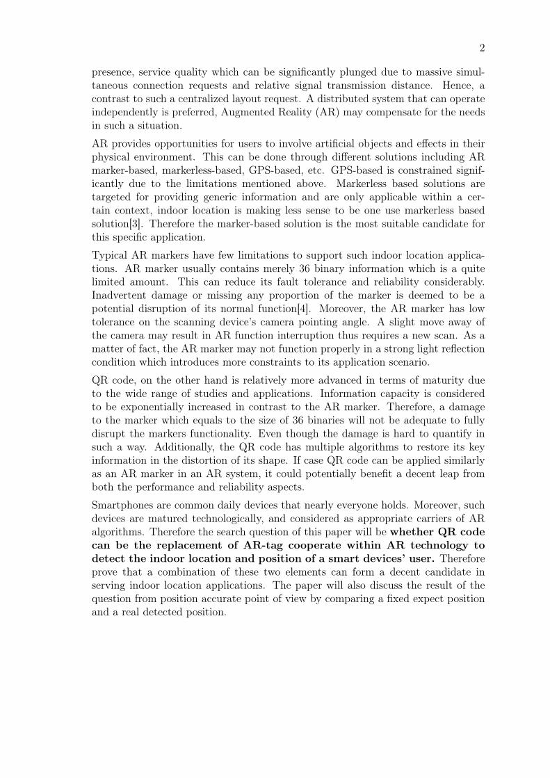
2.2 QR code
Two-dimensional code has big advantages of handling data capacity, data density,data types, and data recovery capability compare to bar code. There are two differ-ent kinds of two-dimensional code: linear bar codes and matrix bar codes accordingto principle, structure, and shape differences [21]. Quick Response Code (QR Code)is one kind of two-dimensional matrix [21] code which invented by Denso Corpo-ration in Japan, 1994. After several years it has been approved by an AIM Stan-dard, an ISO (International Organizations for Standardization) standard, and a JIS(Japanese Industrial Standards) Standard. QR Code has also become the Nationalstandard in China. QR code has been applied to plenty of different fields such aslogistics, mobile applications, manufacturing, and many so on [22].
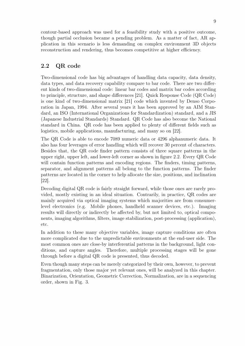
The QR Code is able to encode 7089 numeric data or 4296 alphanumeric data. Italso has four leverages of error handling which will recover 30 percent of characters.Besides that, the QR code finder pattern consists of three square patterns in theupper right, upper left, and lower-left corner as shown in figure 2.2. Every QR Codewill contain function patterns and encoding regions. The finders, timing patterns,separator, and alignment patterns all belong to the function patterns. The finderpatterns are located in the corner to help allocate the size, positions, and inclination[22].
Decoding digital QR code is fairly straight forward, while those ones are rarely pro-vided, mostly existing in an ideal situation. Contrarily, in practice, QR codes aremainly acquired via optical imaging systems which majorities are from consumer-level electronics (e.g. Mobile phones, handheld scanner devices, etc.). Imagingresults will directly or indirectly be affected by, but not limited to, optical compo-nents, imaging algorithms, filters, image stabilization, post-processing (application),etc.
In addition to these many objective variables, image capture conditions are oftenmore complicated due to the unpredictable environments at the end-user side. Themost common ones are close-by interferential patterns in the background, light con-ditions, and capture angles. Therefore, multiple processing stages will be gonethrough before a digital QR code is presented, thus decoded.
Even though many steps can be merely categorized by their own, however, to preventfragmentation, only those major yet relevant ones, will be analyzed in this chapter.Binarization, Orientation, Geometric Correction, Normalization, are in a sequencingorder, shown in Fig. 3.
10
Figure 3: The layout of QR code [22]
2.2.1 QR code system
Binarization QR code as an image captured by a camera on a mobile device willbe converted to a gray-scale format in the first place. Following up by binarization,which is meant to convert a gray level image to a binary image [23].
The threshold method is simple and popular when choosing for binarization. In con-trast to various local threshold algorithm, Niblack was pointed as the best methodby Øivind [23]. However, the Niblack method faces challenges from window size,module influence, and slow performance.
One adaptive local binarization method was designed to compensate for unevenillumination conditions, which bypasses the time duration of window size restrictionby calculating local means with an integral image instead of [24]. This algorithmwas declared with better performance over Niblack and Sauvola’s.
Otsu’s algorithm was summarized as the best method out of 20 threshold ones [4].However, other studies concluded the Otsu method is unsatisfactory in unevenlyilluminated condition [22].
Ohbuchi and Hanaizumi purposed the global threshold method [25], which fragmentthe captured image fist, gray histogram of each block is calculated after and sorted.Thus the middle gray value is referenced as the threshold for that block, where the

11
Figure 4: QR Code Processing Phases
smallest value is used as the global threshold of the image captured. However, thismethod is considered controversial in case environment illumination is variable [26].
To sum it all, to choose a method in binarizing an image can be performance andcondition critical, therefore, it is considered significantly important throughout theentire bar-code identification system.
Orientation Due to the fact that the position of QR code in one image is oftennearly impossible to be guaranteed perfectly aligned, neither horizontally nor ver-tically. Thus, those three identical position detection patterns mentioned above inFig. 2, are commonly utilized in orientating QR code.
Some studies purposed algorithm in cropping captured QR code [27]. The concept isto count out all internal parts of the QR code, which only left the edge. With Houghtransform, peaks and slope can be calculated. One other research concluded one-dimensional pattern match with position detection patterns can perform a rapidlocation method [28]. Hough transform on edge points calculates four edge linesand four vertices, thus conducting control-point transformation and spatial bi-linearinterpolation algorithm according to four vertices forming square principle.
While many other methods are available for orientation through Hough transfor-mation, few researchers implemented tilt correction with the convex hull algorithm[29]. Pixel numbers were reduced during processing by selecting vertices in convexhulls from the pixel list. Traditional straight line detection algorithm requirementon much memory space is overcome by this algorithm. Result in high efficiency and

12
accuracy at positioning QR code had set this method apart.
Another outstanding method allows QR code image rotation with bilinear interpo-lation after guaranteed central alignment with extracted QR code symbol from theimage relevant region [21].
Geometric Correction Due to the fact that image captured which contains QRcode might be geometrically stretched due to various reasons. Some of these reasonscould directly or indirectly involve shooting angles from the camera, orientation, thesurface flatness of the target subject, etc. This geometrical deform on the QR codecould dramatically reduce the accuracy at the recognition process. Therefore, beforethe QR code could be successfully decoded, geometrical correction is commonlyexpected. This geometric correction has to be carefully applied, which the concentricanalysis could have a direct impact on the success rate [22].
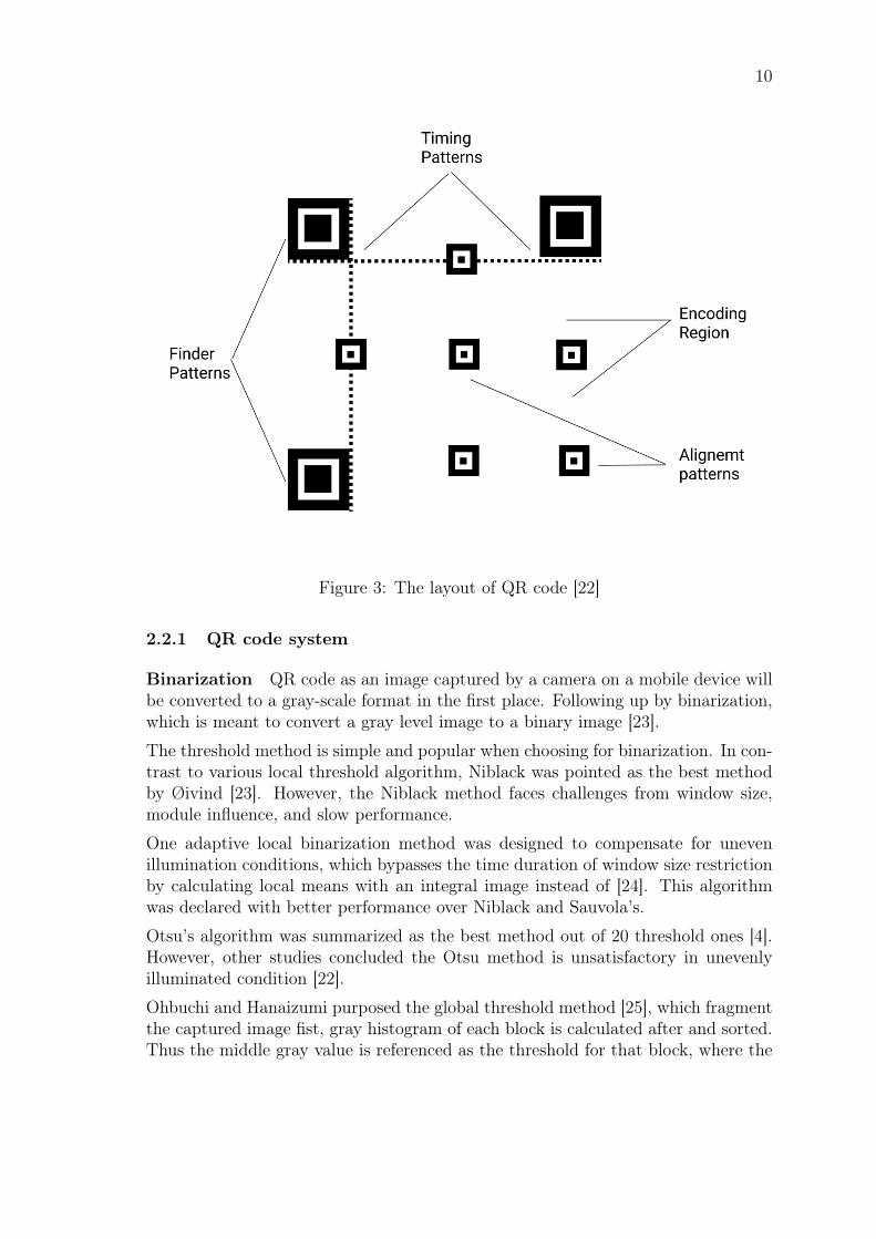
Distorted QR code is seen as rhombus or trapezoid, and most of the result maintainsthe basic properties of irregular quadrilaterals [30]. While setting one corner of themas origin, retrieve corresponding pixels’ quadrilateral region within the calculationarea by conducting a convex hull algorithm, shown in Figure 5, thus re-mappingwhich to the linked area of plane projection transformation [30].
Other studies had shown the possibility of geometric rectification based on the AffineTransformation formula [31]. However, the process is not sufficient to transform theQR code standalone, which also requires localization of alignment patterns andimage sampling after.
Normalization After obtaining the QR code with geometric correction, normal-ization shall be considered to followup. One method was purposed to analyze theedge with Sobel detection, which following by Fourier transform and applies Second-order approximation of Taylor series [28]. Such a method needs to be carried out onboth the horizontal and vertical axis of an acquired QR code. Therefore, each codepoint at both axis intersection will be reordered into bit-stream and decoded at theend.
Security Attacking a QR code can be attacked from both human interaction andautomated systems parts. Attacking from the automated processing period, it can bemanipulated by changing the threat model either by reserve the black and white coloror turning all colors into black. Manipulating the QR code by changing the metadatais another way, QR codes consist of tons of data which includes metadata on theversion, masking, and encode information. A mask in the QR code is responsible fordistributing QR code into good white and black module balance, usually it close to50:50. Attacking masks usually causing the different results of the error correctionalgorithm [1].
QR code can not be decoded without reader software help. For this reason, attackingthe human interaction part is another way of attacking the QR code result. For
13
Figure 5: Conduction of Convex Hull Algorithm
example, phishing and pharming is a typical case, if a QR code is linked withaugmented reality scenarios. A fake website may setup and redirect the user to thetarget website by changing the QR code. This is really dangerous that users do nothave any possibility to verify if the link is not mortified[1].
Because nowadays QR code used to link many advertisements, fraud by QR codeis also a security issue. An attacker may fake a website to link the QR code tothe cloned website. The transaction will happen on the cloned website without areal contract. In addition to the above, attacking through the code reader soft-ware by command injection or buffer overflows. This is a serious leak, the attackermay control the entire phone, some credential data of mobile uses include contact
14
information or password[1].
2.3 Related Works
There are already some projects and papers related to applying QR code in aug-mented reality according to the research. In this section, we will discuss some similarproposals that have been made before and also the differences from what this paperwill do.
The team from Yuan-ze University has encoded the 3D model of the product into aQR code. That means when a user scans the QR code of a product, the 3D model ofthe product could appear on the smart device. They have mostly used ARToolKit totrack the three position detection patterns of the target QR code and also used thesame library to build the 3D model on the QR code. The advantage of choosing a QRcode than AR tag is that the QR code does not require any registration every timewhen a new pattern is introduced. The system could directly extract the productinformation from the QR code. Moreover, the QR code has better error tolerance,the system could still extract the 3D model information even though the QR code isnot facing the camera straightly [32]. Besides that, the team from Pohang Universityhas done quite similar research as well by using the same library and approaches [3].
Besides that, another group of researchers from Yuan-ze university also have thesame approaches to developing the QR code-based AR system. However, they uti-lized the different features of QR code-named SIFT, which is broadly used to enhancethe accuracy of QR code tracking and error tolerance [33].
Moreover, some interesting research has been done by University College London.They have been built a QR code-based indoor navigation system. When a user usestheir phone to scan the QR code, the system will calculate the Point Of Interest(POI) data which is pre-saved in the system and sent back to the client-side. Afterthat, some direction suggestions will be given on the user’s screen based on ARtechnology [34].
There is some research related to utilizing the QR code to calibrate the mobileAR application. Users could use mobile to scan the QR code, which is located indifferent indoor places. By scanning the QR code, users could download the locationinformation integrated into the QR code. The AR application will automaticallyextract the location information and provide better AR service [35].
According to the research presented above, most of the current research is focusingon implementing a mobile based application. Besides that, there are many types ofresearch done to encode the data in the QR code and trying to extract the data whenthe user scans the QR. In the end, use the data in the AR applications to increasethe quality. This paper will focus on building a web application that enables usersto scan the QR code with any device with a camera that has a modern browserinstalled. Building 3D models on top of the QR code in order to get the user’sposition, eventually making user interaction between smart devices and real-life

15
environments.
From the implementation point of view, most existing research has been used inthe Zxing library to implement the QR code detection part, which will be the samesolution also used in this paper. Besides that, because many of them are mobilesolutions, there are a variety of solutions that have been stated. This paper willbasically use the POSIT algorithm developed by an existing library to implementthe 3D model part.
16
3 Project and Experiments
The following paragraph will focus on the discussion about applying QR code toaugment reality. First of all, targeting the current AR system problem and goal ofthe experiments which calculate the relative position between the scanning cameraand original QR code. Besides that, the paragraph will also present the main differ-ences between utilize the QR code and fiducial markers and the benefits of applyingthe QR code to augment reality.
Secondly, the paper will present the processing of the project. It has been mainlydivided into five steps in order to reach the final goal. In the process section, itforces on the technical solution of the whole experiment, several AR and QR codelibrary(e.g. Zxing, openCV and etc) also utilized in this project. The paper willanalyze the method of each library and mathematics models.
Finally, it will go through the conclusion and limitation of the experiment andanalyze the result.
3.1 Introduction of the experiments
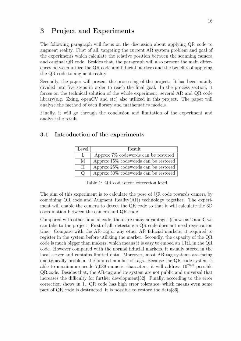
Level ResultL Approx 7% codewords can be restoredM Approx 15% codewords can be restoredH Approx 25% codewords can be restoredQ Approx 30% codewords can be restored
Table 1: QR code error correction level
The aim of this experiment is to calculate the pose of QR code towards camera bycombining QR code and Augment Reality(AR) technology together. The experi-ment will enable the camera to detect the QR code so that it will calculate the 3Dcoordination between the camera and QR code.
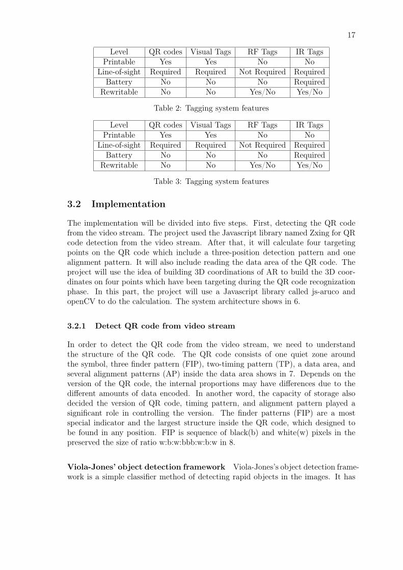
Compared with other fiducial code, there are many advantages (shows as 2 and3) wecan take to the project. First of all, detecting a QR code does not need registrationtime. Compare with the AR-tag or any other AR fiducial markers, it required toregister in the system before utilizing the marker. Secondly, the capacity of the QRcode is much bigger than makers, which means it is easy to embed an URL in the QRcode. However compared with the normal fiducial markers, it usually stored in thelocal server and contains limited data. Moreover, most AR-tag systems are facingone typically problem, the limited number of tags. Because the QR code system isable to maximum encode 7,089 numeric characters, it will address 107098 possibleQR code. Besides that, the AR-tag and its system are not public and universal thatincreases the difficulty for further development[32]. Finally, according to the errorcorrection shows in 1. QR code has high error tolerance, which means even somepart of QR code is destructed, it is possible to restore the data[36].
17
Level QR codes Visual Tags RF Tags IR TagsPrintable Yes Yes No No
Line-of-sight Required Required Not Required RequiredBattery No No No Required
Rewritable No No Yes/No Yes/No
Table 2: Tagging system features
Level QR codes Visual Tags RF Tags IR TagsPrintable Yes Yes No No
Line-of-sight Required Required Not Required RequiredBattery No No No Required
Rewritable No No Yes/No Yes/No
Table 3: Tagging system features
3.2 Implementation
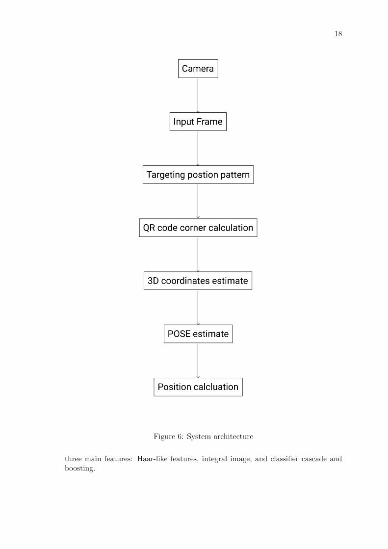
The implementation will be divided into five steps. First, detecting the QR codefrom the video stream. The project used the Javascript library named Zxing for QRcode detection from the video stream. After that, it will calculate four targetingpoints on the QR code which include a three-position detection pattern and onealignment pattern. It will also include reading the data area of the QR code. Theproject will use the idea of building 3D coordinations of AR to build the 3D coor-dinates on four points which have been targeting during the QR code recognizationphase. In this part, the project will use a Javascript library called js-aruco andopenCV to do the calculation. The system architecture shows in 6.
3.2.1 Detect QR code from video stream
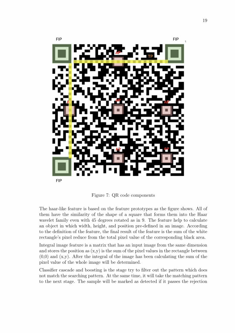
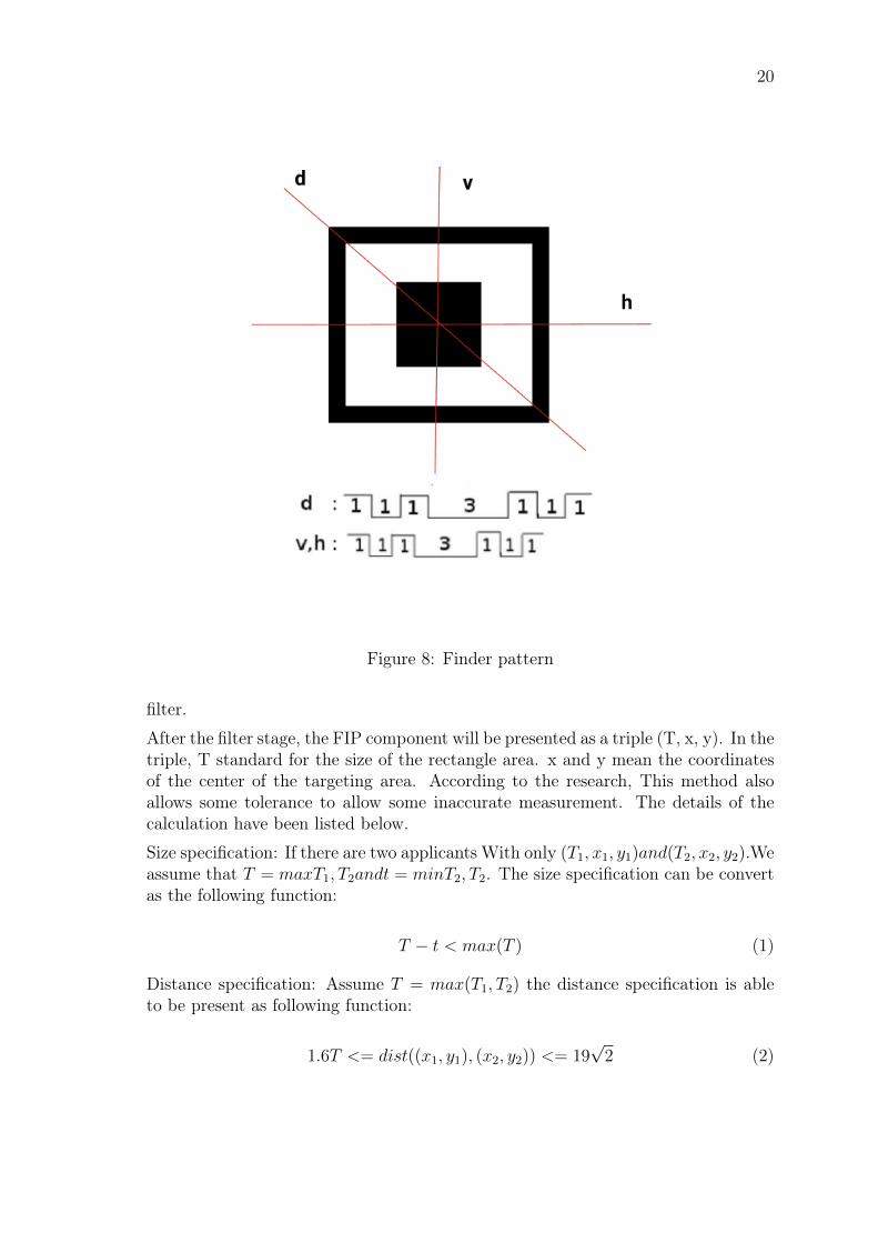
In order to detect the QR code from the video stream, we need to understandthe structure of the QR code. The QR code consists of one quiet zone aroundthe symbol, three finder pattern (FIP), two-timing pattern (TP), a data area, andseveral alignment patterns (AP) inside the data area shows in 7. Depends on theversion of the QR code, the internal proportions may have differences due to thedifferent amounts of data encoded. In another word, the capacity of storage alsodecided the version of QR code, timing pattern, and alignment pattern played asignificant role in controlling the version. The finder patterns (FIP) are a mostspecial indicator and the largest structure inside the QR code, which designed tobe found in any position. FIP is sequence of black(b) and white(w) pixels in thepreserved the size of ratio w:b:w:bbb:w:b:w in 8.
Viola-Jones’ object detection framework Viola-Jones’s object detection frame-work is a simple classifier method of detecting rapid objects in the images. It has
18
Figure 6: System architecture
three main features: Haar-like features, integral image, and classifier cascade andboosting.
19
Figure 7: QR code components
The haar-like feature is based on the feature prototypes as the figure shows. All ofthem have the similarity of the shape of a square that forms them into the Haarwavelet family even with 45 degrees rotated as in 9. The feature help to calculatean object in which width, height, and position pre-defined in an image. Accordingto the definition of the feature, the final result of the feature is the sum of the whiterectangle’s pixel reduce from the total pixel value of the corresponding black area.
Integral image feature is a matrix that has an input image from the same dimensionand stores the position as (x,y) is the sum of the pixel values in the rectangle between(0,0) and (x,y). After the integral of the image has been calculating the sum of thepixel value of the whole image will be determined.
Classifier cascade and boosting is the stage try to filter out the pattern which doesnot match the searching pattern. At the same time, it will take the matching patternto the next stage. The sample will be marked as detected if it passes the rejection
20
Figure 8: Finder pattern
filter.
After the filter stage, the FIP component will be presented as a triple (T, x, y). In thetriple, T standard for the size of the rectangle area. x and y mean the coordinatesof the center of the targeting area. According to the research, This method alsoallows some tolerance to allow some inaccurate measurement. The details of thecalculation have been listed below.
Size specification: If there are two applicants With only (T1, x1, y1)and(T2, x2, y2).Weassume that T = maxT1, T2andt = minT2, T2. The size specification can be convertas the following function:
T − t < max(T ) (1)
Distance specification: Assume T = max(T1, T2) the distance specification is ableto be present as following function:
1.6T <= dist((x1, y1), (x2, y2)) <= 19√2 (2)
21
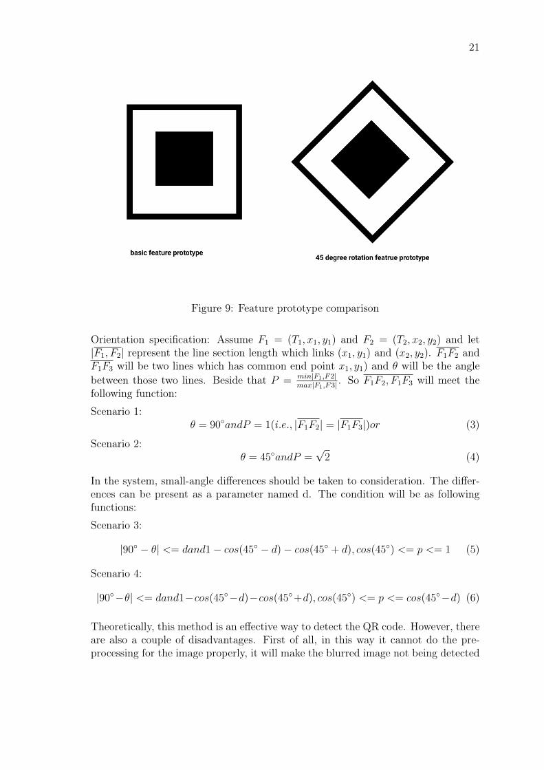
Figure 9: Feature prototype comparison
Orientation specification: Assume F1 = (T1, x1, y1) and F2 = (T2, x2, y2) and let|F1, F2| represent the line section length which links (x1, y1) and (x2, y2). F1F2 andF1F3 will be two lines which has common end point x1, y1) and θ will be the anglebetween those two lines. Beside that P = min|F1,F2|
max|F1,F3| . So F1F2, F1F3 will meet thefollowing function:
Scenario 1:θ = 90◦andP = 1(i.e., |F1F2| = |F1F3|)or (3)
Scenario 2:θ = 45◦andP =
√2 (4)
In the system, small-angle differences should be taken to consideration. The differ-ences can be present as a parameter named d. The condition will be as followingfunctions:
Scenario 3:
|90◦ − θ| <= dand1− cos(45◦ − d)− cos(45◦ + d), cos(45◦) <= p <= 1 (5)
Scenario 4:
|90◦−θ| <= dand1−cos(45◦−d)−cos(45◦+d), cos(45◦) <= p <= cos(45◦−d) (6)
Theoretically, this method is an effective way to detect the QR code. However, thereare also a couple of disadvantages. First of all, in this way it cannot do the pre-processing for the image properly, it will make the blurred image not being detected

22
correctly. In addition, it required a large amount of training set and it will alsoinfluence the detection rate.
In the experiment, it utilized the JavaScript library named Zxing for detecting theQR code from the video stream. Zxing is also using the Viola-Jones’ object detectionframework concept, because of the library we can directly use in the project. In orderto successfully detect the position point on the QR code, we first try to detect theQR code from the screen instead of a video stream to verify the functionality workingproperly. The project used "BrowserQRCodeReader" from "Zxing" library to detectthe QR code on the screen like the following code snippet listing 1 shows. If the QRcode is missing the TP(timing pattern) points, it is still possible to recognize the QRcode. we will calculate the corresponding AP(alignment pattern) point according tothe position of FIP points for further references. After catching the position pointson the QR code, it passes the array named results for further rendering. To verifiedit has been detected the correct points, we also used the Javascript canvas renderinglibrary "react-knova" to rendering the FIP and AP points on the QR code. Thefinal results show on 10, the green square points shows the scanning result of FIPand AP points.
Figure 10: Static QR code detect by Zxing
After implementing the static QR code detection, the project will move forwardwith detecting the QR code from the video stream. There are pre-requirements inorder to archive the goal. The web application needs to ask the user for web camerapermission. After that, the web app will get the data of the camera and start tomanipulate the camera in order to recognize the QR code from the video stream.This part of the project also utilized the Zxing library which already provides afeature from asking user camera permission to get the camera information. Afterthe camera detects QR code successfully, the web application will also render thegreen dots on the FIP and AP to indicate the detection is working properly.

23
const Scanner = () => {const [results, setResults] = useState('')
const getQrCodeResult = url => {const codeReader = new BrowserQRCodeReader()codeReader
.decodeFromImage('sample_code', url)
.then(result => {console.log('result', JSON.stringify(result.resultPoints))setResults(result)
}).catch(err => console.error(err))
}return (
<div className="page">{/* <h2>result: {results}</h2> */}<Stage width={1200} height={1200}>
<Layer><Text text="Try click on rect" />{results.resultPoints &&
results.resultPoints.map((point, index) => (<DotCmp
key={index}x={point.x}y={point.y}estimatedModuleSize={point.estimatedModuleSize}
/>))}
</Layer></Stage><img src={sample} alt="log" id="sample_code" /><button onClick={() => getQrCodeResult(sample)}>Start Scan</button>
</div>
)}
export default Scanner
Listing 1: Scan static QR code
The following code snippet shows in listing 2 present the way to get the camera de-vice information and how to manipulate the camera in order to catch the QR code.It will first require the camera permission by requiring the function "BrowserQR-
24
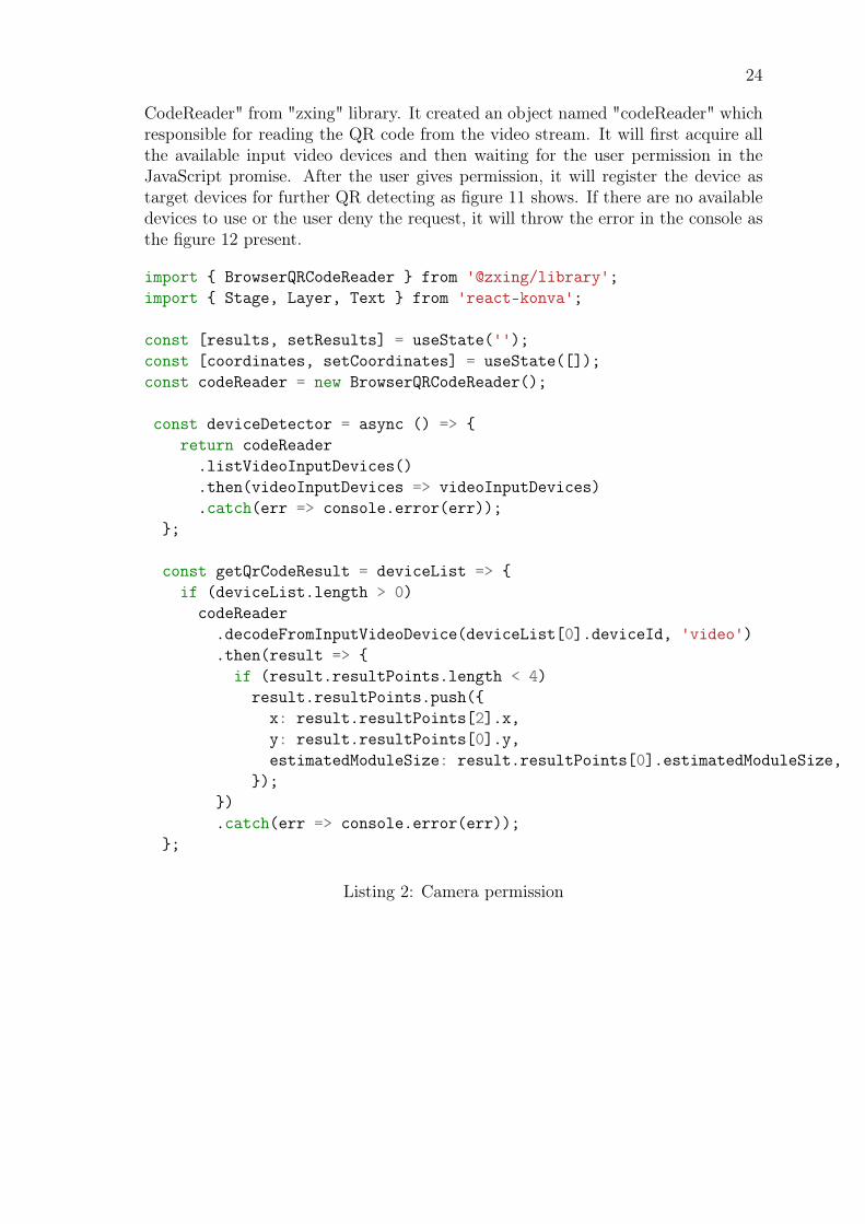
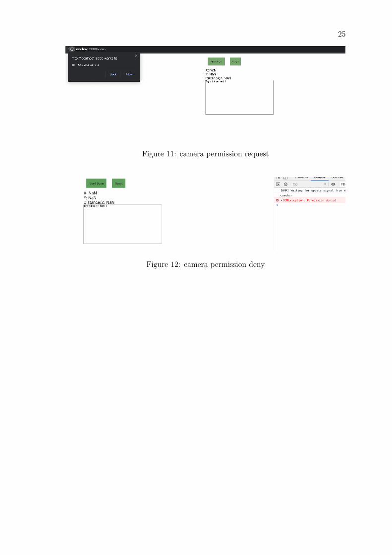
CodeReader" from "zxing" library. It created an object named "codeReader" whichresponsible for reading the QR code from the video stream. It will first acquire allthe available input video devices and then waiting for the user permission in theJavaScript promise. After the user gives permission, it will register the device astarget devices for further QR detecting as figure 11 shows. If there are no availabledevices to use or the user deny the request, it will throw the error in the console asthe figure 12 present.
import { BrowserQRCodeReader } from '@zxing/library';import { Stage, Layer, Text } from 'react-konva';
const [results, setResults] = useState('');const [coordinates, setCoordinates] = useState([]);const codeReader = new BrowserQRCodeReader();
const deviceDetector = async () => {return codeReader
.listVideoInputDevices()
.then(videoInputDevices => videoInputDevices)
.catch(err => console.error(err));};
const getQrCodeResult = deviceList => {if (deviceList.length > 0)
codeReader.decodeFromInputVideoDevice(deviceList[0].deviceId, 'video').then(result => {
if (result.resultPoints.length < 4)result.resultPoints.push({
x: result.resultPoints[2].x,y: result.resultPoints[0].y,estimatedModuleSize: result.resultPoints[0].estimatedModuleSize,
});}).catch(err => console.error(err));
};
Listing 2: Camera permission
25
Figure 11: camera permission request
Figure 12: camera permission deny
26
import { BrowserQRCodeReader } from '@zxing/library';import { Stage, Layer, Text } from 'react-konva';
const [results, setResults] = useState('');const [coordinates, setCoordinates] = useState([]);
const getQrCodeResult = deviceList => {if (deviceList.length > 0)
codeReader.decodeFromInputVideoDevice(deviceList[0].deviceId, 'video').then(result => {
if (result.resultPoints.length < 4)result.resultPoints.push({
x: result.resultPoints[2].x,y: result.resultPoints[0].y,estimatedModuleSize: result.resultPoints[0].estimatedModuleSize,
});}).catch(err => console.error(err));
};
Listing 3: Calculate target points on QR code
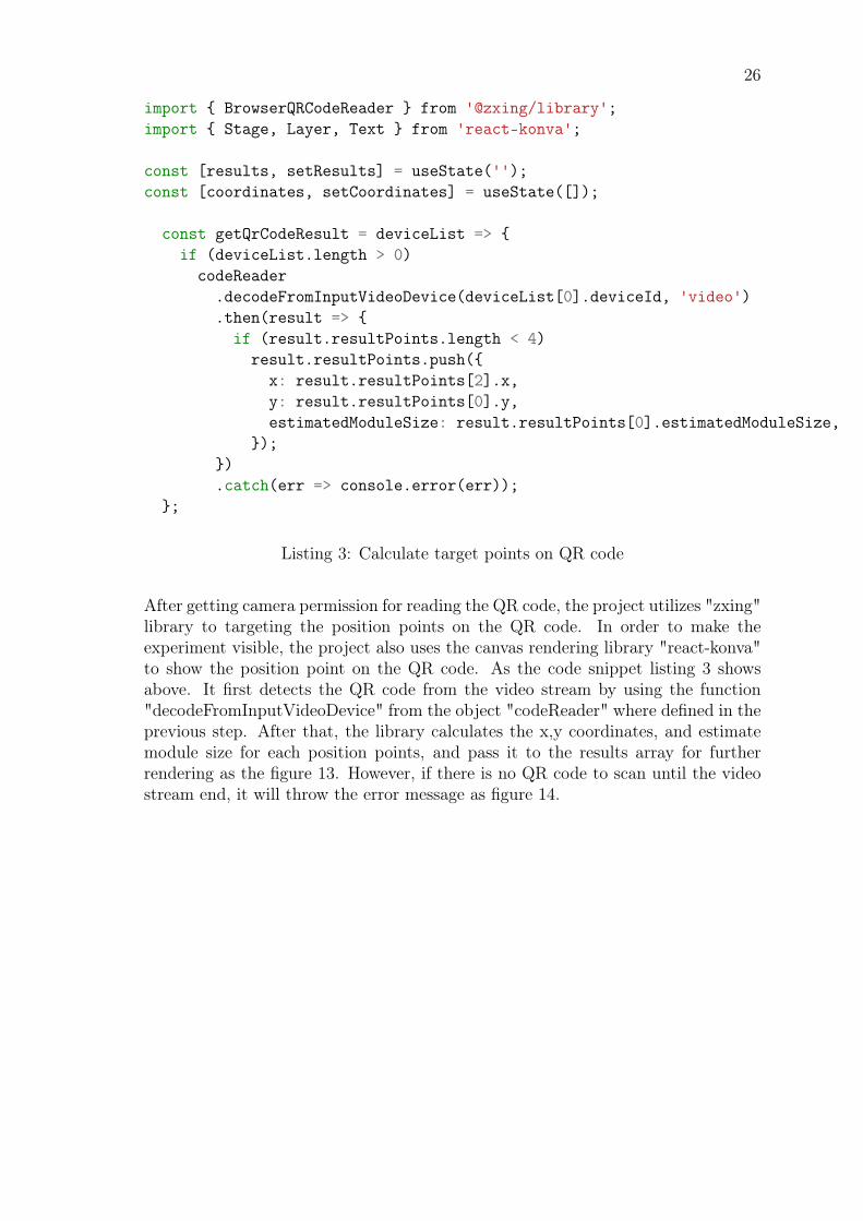
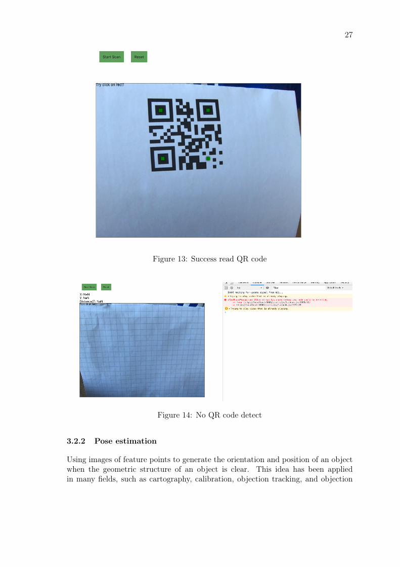
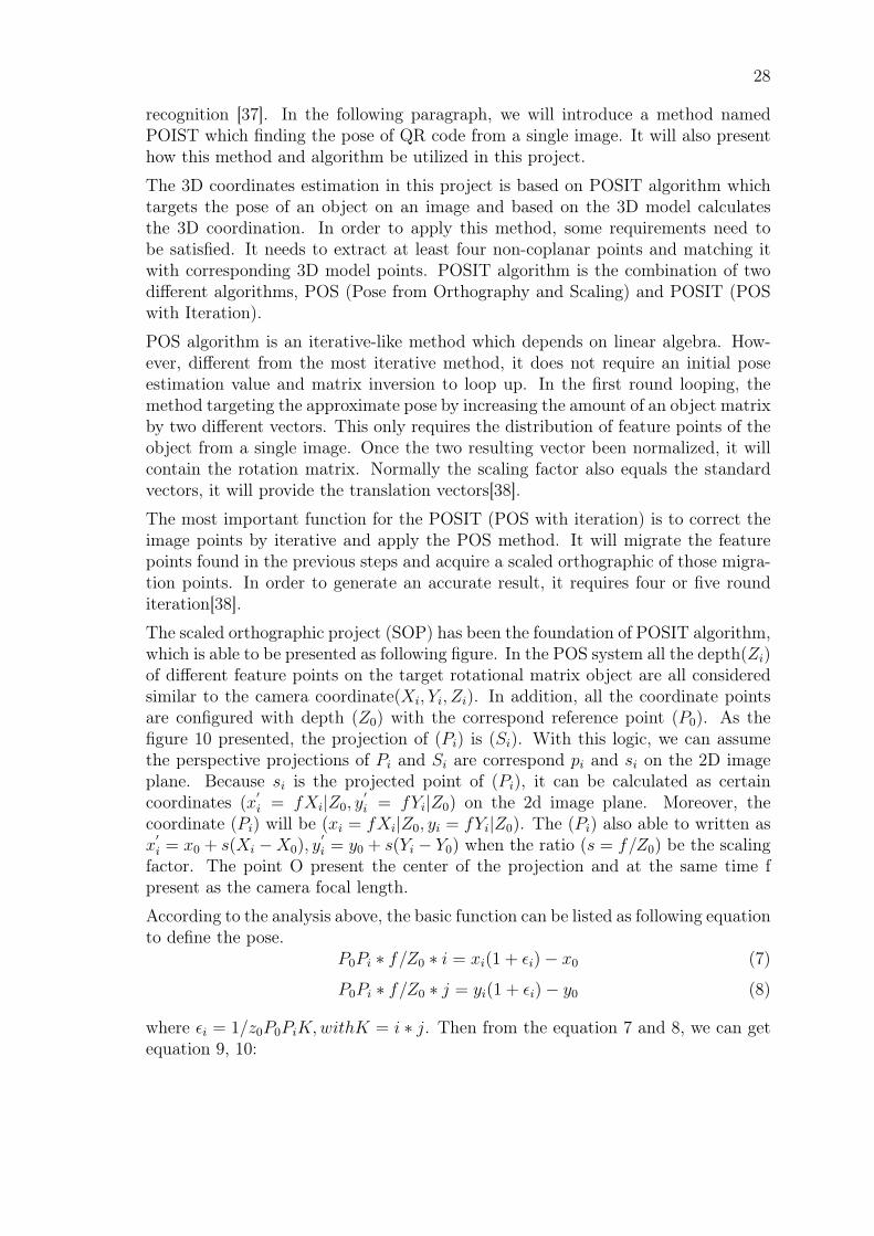
After getting camera permission for reading the QR code, the project utilizes "zxing"library to targeting the position points on the QR code. In order to make theexperiment visible, the project also uses the canvas rendering library "react-konva"to show the position point on the QR code. As the code snippet listing 3 showsabove. It first detects the QR code from the video stream by using the function"decodeFromInputVideoDevice" from the object "codeReader" where defined in theprevious step. After that, the library calculates the x,y coordinates, and estimatemodule size for each position points, and pass it to the results array for furtherrendering as the figure 13. However, if there is no QR code to scan until the videostream end, it will throw the error message as figure 14.
27
Figure 13: Success read QR code
Figure 14: No QR code detect
3.2.2 Pose estimation
Using images of feature points to generate the orientation and position of an objectwhen the geometric structure of an object is clear. This idea has been appliedin many fields, such as cartography, calibration, objection tracking, and objection
28
recognition [37]. In the following paragraph, we will introduce a method namedPOIST which finding the pose of QR code from a single image. It will also presenthow this method and algorithm be utilized in this project.
The 3D coordinates estimation in this project is based on POSIT algorithm whichtargets the pose of an object on an image and based on the 3D model calculatesthe 3D coordination. In order to apply this method, some requirements need tobe satisfied. It needs to extract at least four non-coplanar points and matching itwith corresponding 3D model points. POSIT algorithm is the combination of twodifferent algorithms, POS (Pose from Orthography and Scaling) and POSIT (POSwith Iteration).
POS algorithm is an iterative-like method which depends on linear algebra. How-ever, different from the most iterative method, it does not require an initial poseestimation value and matrix inversion to loop up. In the first round looping, themethod targeting the approximate pose by increasing the amount of an object matrixby two different vectors. This only requires the distribution of feature points of theobject from a single image. Once the two resulting vector been normalized, it willcontain the rotation matrix. Normally the scaling factor also equals the standardvectors, it will provide the translation vectors[38].
The most important function for the POSIT (POS with iteration) is to correct theimage points by iterative and apply the POS method. It will migrate the featurepoints found in the previous steps and acquire a scaled orthographic of those migra-tion points. In order to generate an accurate result, it requires four or five rounditeration[38].
The scaled orthographic project (SOP) has been the foundation of POSIT algorithm,which is able to be presented as following figure. In the POS system all the depth(Zi)of different feature points on the target rotational matrix object are all consideredsimilar to the camera coordinate(Xi, Yi, Zi). In addition, all the coordinate pointsare configured with depth (Z0) with the correspond reference point (P0). As thefigure 10 presented, the projection of (Pi) is (Si). With this logic, we can assumethe perspective projections of Pi and Si are correspond pi and si on the 2D imageplane. Because si is the projected point of (Pi), it can be calculated as certaincoordinates (x
′i = fXi|Z0, y
′i = fYi|Z0) on the 2d image plane. Moreover, the
coordinate (Pi) will be (xi = fXi|Z0, yi = fYi|Z0). The (Pi) also able to written asx
′i = x0 + s(Xi −X0), y
′i = y0 + s(Yi − Y0) when the ratio (s = f/Z0) be the scaling
factor. The point O present the center of the projection and at the same time fpresent as the camera focal length.
According to the analysis above, the basic function can be listed as following equationto define the pose.
P0Pi ∗ f/Z0 ∗ i = xi(1 + εi)− x0 (7)
P0Pi ∗ f/Z0 ∗ j = yi(1 + εi)− y0 (8)
where εi = 1/z0P0PiK,withK = i ∗ j. Then from the equation 7 and 8, we can getequation 9, 10:

29
Figure 15: Illustration of POSIT
P0Pi ∗ I = xi(1 + εi)− x0 (9)
P0Pi ∗ J = yi(1 + εi)− y0 (10)
Where I = f/z0i, j = f/z0j
The equations listed above are POS (pose from orthography and scaling) which ableto calculate the I and J according to the linear system and also determine the I andJ. Repeating the calculation will get more accurate i and j values which present theconcept of POSIT( POS with iterations) algorithm [6].
This project used a Javascript library named Js-aruco to estimate the coordinateson the camera. Js-aruco is a Javascript library based on OpenCv and also sup-
30
ported by POSIT algorithm. It has been used to estimate the coordinates and posesfor augments reality. The following code snippet listing 4 shows how it been im-plemented in this project. After successfully recognized the QR code and targetposition pattern, it first utilized the "posit" function from "Js-aruco" to build thePOIST object based on model size and canvas size. After that, we pass the positionpoints of the target QR code to the POSIT object to build the 3D coordinates oneach position point. Finally, the coordinates passed to the "result" array and it willbe shown as output. The project will also render the position points on the QR toverify it finds the points properly. The result will show the relative position (x,y,z)between the sample QR code in millimeter and QR code.

31
const getQrCodeResult = deviceList => {if (deviceList.length > 0)
codeReader.decodeFromInputVideoDevice(deviceList[0].deviceId, 'video').then(result => {
if (result.resultPoints.length < 4)result.resultPoints.push({
x: result.resultPoints[2].x,y: result.resultPoints[0].y,estimatedModuleSize: result.resultPoints[0].estimatedModuleSize,
});
let modelSize = result.resultPoints[0].estimatedModuleSize * 10;let posit = new POS1.Posit(modelSize, CANVAS_SIZE);
let pose = posit.pose(result.resultPoints);setCoordinates(pose.bestTranslation);setResults(result);
}).catch(err => console.error(err));
};return (
<div><button
onClick={async () => {const deviceLisit = await deviceDetector()getQrCodeResult(deviceLisit)
}}>
Start Scan</button><button onClick={() => document.location.reload(false)}>Reset</button><div>X: {Number(coordinates[0]).toFixed(2)}</div><div>Y: {Number(coordinates[1]).toFixed(2)}</div><div>Distance/Z: {Number(coordinates[2]).toFixed(2)}</div><div className="page"><Stage width={CANVAS_SIZE} height={CANVAS_SIZE} key="test"><Layer key="test1">{results.resultPoints &&results.resultPoints.map((point, index) => (<DotCmp key={index} x={point.x}y={point.y}
estimatedModuleSize={point.estimatedModuleSize}/>))}</Layer></Stage><video id="video"></video></div></div>)
Listing 4: Estimate Pose on QR code

32
3.3 Demonstrate and result in analysis
3.3.1 Demonstrate
This paragraph will demonstrate and discuss how the project finally estimates theQR code relative position towards to camera. As many discussions presented inthe previous paragraphs, after presenting a QR code in front of the camera. A 3Dcoordination will be estimated based on the QR code, eventually a relative positionwill calculate as (x,y,z) towards the camera. As in the scanning result shown infigure 16, there are three figures on the top of the scanning area: x, y, z, which isthe relation position towards the camera. The (x, y) shows the direction towardsthe camera and y presents the distance between the QR code and the camera.
Figure 16: three testing sample QR code
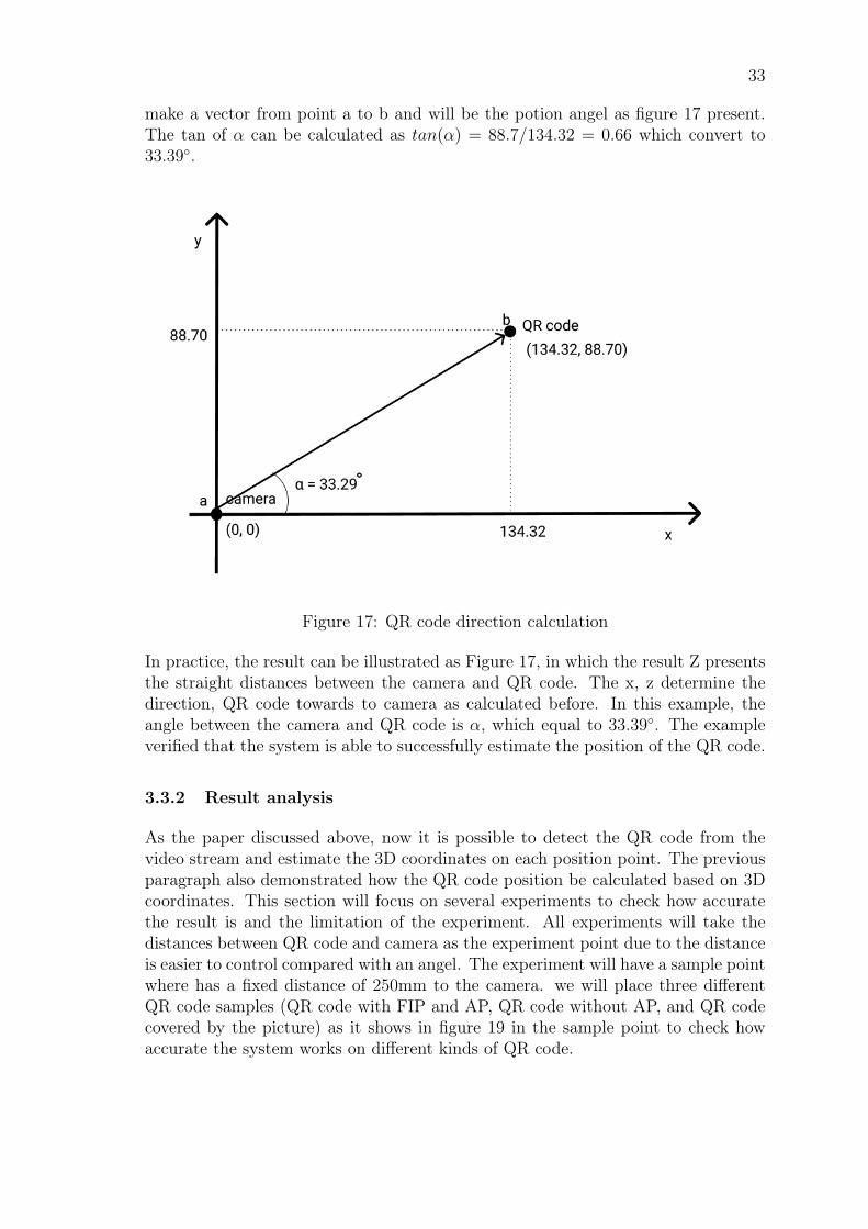
To calculate the direction towards to camera we will need to know x, y point. wewill the figure from the example above to discuss the calculation process. As we canassume the point of the camera on the x, y coordination is (0,0), then the QR codeis (134.32, 88.70). With the known camera point(a) and QR code point(b) we can
33
make a vector from point a to b and will be the potion angel as figure 17 present.The tan of α can be calculated as tan(α) = 88.7/134.32 = 0.66 which convert to33.39◦.
Figure 17: QR code direction calculation
In practice, the result can be illustrated as Figure 17, in which the result Z presentsthe straight distances between the camera and QR code. The x, z determine thedirection, QR code towards to camera as calculated before. In this example, theangle between the camera and QR code is α, which equal to 33.39◦. The exampleverified that the system is able to successfully estimate the position of the QR code.
3.3.2 Result analysis
As the paper discussed above, now it is possible to detect the QR code from thevideo stream and estimate the 3D coordinates on each position point. The previousparagraph also demonstrated how the QR code position be calculated based on 3Dcoordinates. This section will focus on several experiments to check how accuratethe result is and the limitation of the experiment. All experiments will take thedistances between QR code and camera as the experiment point due to the distanceis easier to control compared with an angel. The experiment will have a sample pointwhere has a fixed distance of 250mm to the camera. we will place three differentQR code samples (QR code with FIP and AP, QR code without AP, and QR codecovered by the picture) as it shows in figure 19 in the sample point to check howaccurate the system works on different kinds of QR code.
34
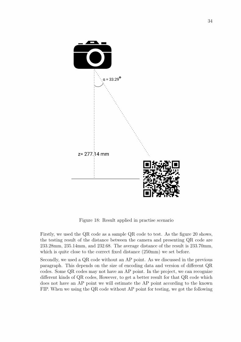
Figure 18: Result applied in practise scenario
Firstly, we used the QR code as a sample QR code to test. As the figure 20 shows,the testing result of the distance between the camera and presenting QR code are233.28mm, 235.14mm, and 232.68. The average distance of the result is 233.70mm,which is quite close to the correct fixed distance (250mm) we set before.
Secondly, we used a QR code without an AP point. As we discussed in the previousparagraph. This depends on the size of encoding data and version of different QRcodes. Some QR codes may not have an AP point. In the project, we can recognizedifferent kinds of QR codes, However, to get a better result for that QR code whichdoes not have an AP point we will estimate the AP point according to the knownFIP. When we using the QR code without AP point for testing, we got the following

35
Figure 19: three testing sample QR code
Figure 20: QR code testing result
distance result: 442.02mm, 438.23mm, and 428.13 and the mean of the result is436.13 as the figure 21 shows. The average result has 186.13mm from the targetdistance we have set before.
Figure 21: QR code without AP testing result
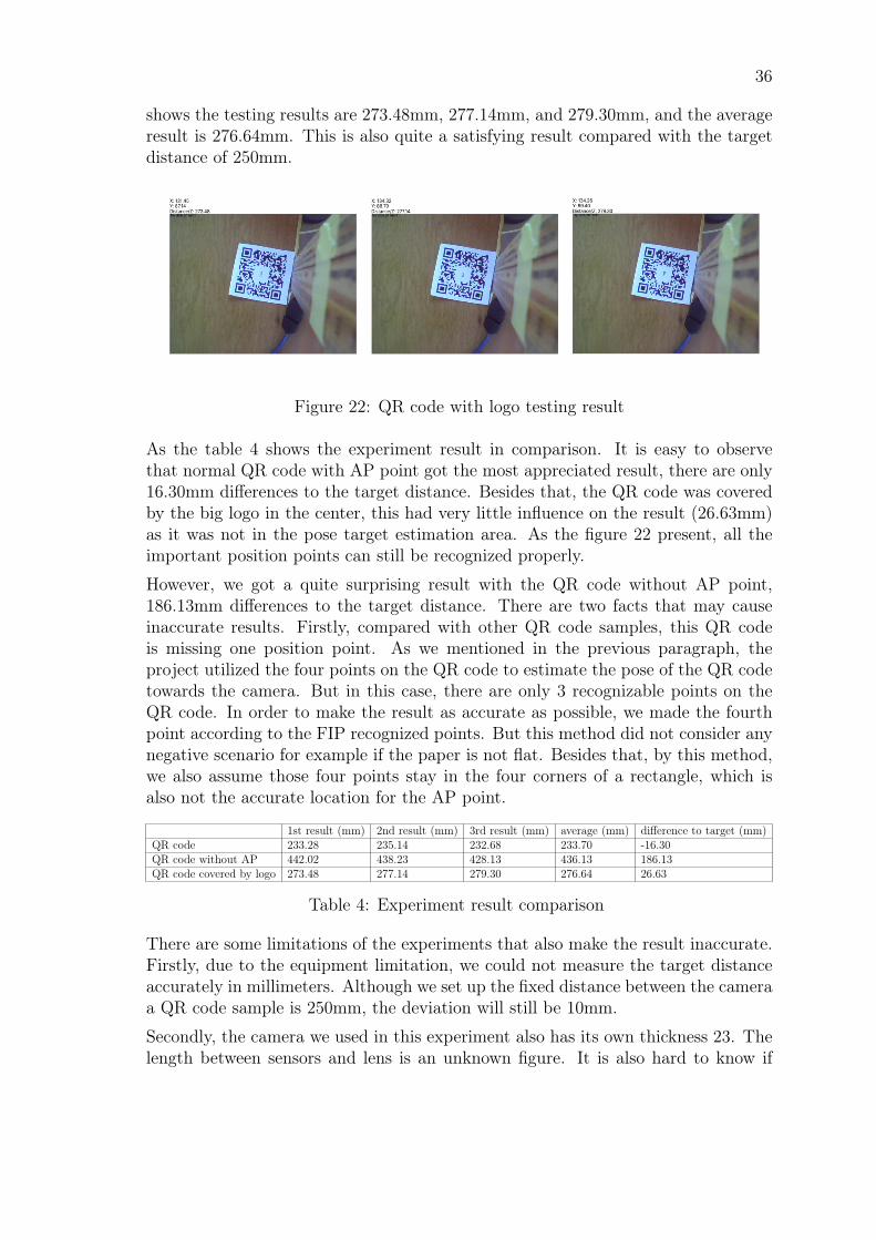
Finally, we used a QR code that has been covered by the big logo in the centerto check whether there are some influences. We got the testing result as figure 22
36
shows the testing results are 273.48mm, 277.14mm, and 279.30mm, and the averageresult is 276.64mm. This is also quite a satisfying result compared with the targetdistance of 250mm.
Figure 22: QR code with logo testing result
As the table 4 shows the experiment result in comparison. It is easy to observethat normal QR code with AP point got the most appreciated result, there are only16.30mm differences to the target distance. Besides that, the QR code was coveredby the big logo in the center, this had very little influence on the result (26.63mm)as it was not in the pose target estimation area. As the figure 22 present, all theimportant position points can still be recognized properly.
However, we got a quite surprising result with the QR code without AP point,186.13mm differences to the target distance. There are two facts that may causeinaccurate results. Firstly, compared with other QR code samples, this QR codeis missing one position point. As we mentioned in the previous paragraph, theproject utilized the four points on the QR code to estimate the pose of the QR codetowards the camera. But in this case, there are only 3 recognizable points on theQR code. In order to make the result as accurate as possible, we made the fourthpoint according to the FIP recognized points. But this method did not consider anynegative scenario for example if the paper is not flat. Besides that, by this method,we also assume those four points stay in the four corners of a rectangle, which isalso not the accurate location for the AP point.
1st result (mm) 2nd result (mm) 3rd result (mm) average (mm) difference to target (mm)QR code 233.28 235.14 232.68 233.70 -16.30QR code without AP 442.02 438.23 428.13 436.13 186.13QR code covered by logo 273.48 277.14 279.30 276.64 26.63
Table 4: Experiment result comparison
There are some limitations of the experiments that also make the result inaccurate.Firstly, due to the equipment limitation, we could not measure the target distanceaccurately in millimeters. Although we set up the fixed distance between the cameraa QR code sample is 250mm, the deviation will still be 10mm.
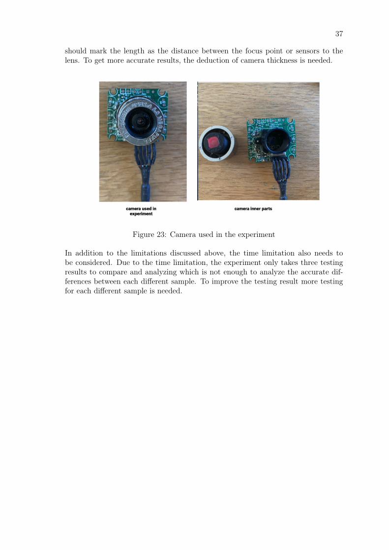
Secondly, the camera we used in this experiment also has its own thickness 23. Thelength between sensors and lens is an unknown figure. It is also hard to know if
37
should mark the length as the distance between the focus point or sensors to thelens. To get more accurate results, the deduction of camera thickness is needed.
Figure 23: Camera used in the experiment
In addition to the limitations discussed above, the time limitation also needs tobe considered. Due to the time limitation, the experiment only takes three testingresults to compare and analyzing which is not enough to analyze the accurate dif-ferences between each different sample. To improve the testing result more testingfor each different sample is needed.
38
4 Conclusion
The paper first introduced the background of QR code and Augmented Reality, andhow they have been implemented in our current life. Additionally, a combination ofboth technologies was assumed as an alternative solution to the Bluetooth beaconpowered indoor location and navigation system.
After the background researching, we set up the goal of an experiment that imple-ments an application that combines the feature of QR code and AR technology toread the distance between the target QR code to the camera and information ofposition from QR code towards camera. This implementation will bring the benefitsof QR code and AR ideas together. Because QR code is wildly used in our dailylife and has better tolerance than AR mark. For this reason, the project used a QRcode as a target object marker.
The project has used POSIT algorithm to estimate the 3D coordinates on the QRcode in order to calculate the distance and position between the target object tothe camera. This is also the main algorithm utilized in the current AR object buildfeature. Finally, the project was able to calculate the distances and position betweenthe QR code to the camera. Therefore, the research question could be answered thata combination of QR code and AR technology could serve a satisfyingindoor location and position result. Moreover, the solution will also bring easieraccessibility to the end-user.
In addition, the experiment has been designed to test and verify the result. Threedifferent sample QR codes have been used in the experiment: normal QR code,QR code without AP, and QR code covered by logon in the center. The results oftesting, limitation, and improvement ideas have also been discussed.

39
References
1 M. M. L. M. S. M. S. E. W. Peter Kieseberg, Manuel Leithner, “Qr code security,”2010.
2 M. A. P. C. E. D. M. I. Julie Carmigniani, Borko Furht, “Augmented realitytechnologies, systems and applications,” 2011.
3 H. J. Kong Ruan, “An augemented reality system using qr code as marker inandriod smartphone,” 2012.
4 A. W. P.K Sahoo, S Soltani, “A survey of thresholding techniques,” 1988.
5 T.-W. C. Jian-tung Wang, Chia-Nian Shyi, “Design and implementation of aug-mented reality system collaborating with qr code,” 2010.
6 K.-H. H. S.-S. L. M.-S. H. S.-c. C. S. J. H. W.-J. Y. Dae-Seung Kim, HoonJoo Yang, “Three-dimensional natural head position reproduction using a single-facial photograph based on the posit method,” 2004.
7 B. F. Julie Carmigniani, “Augmented reality: An overview,” 2011.
8 L. B. Rosenberg, “Virtual fixtures: Perceptual tools for telerobotic manipula-tion,” 1993.
9 N. Albusberger, “Determinants of diffusion of virtual reality,” 2015.
10 P. Brown, “How to transform your classroom with augmented reality,” 2015.
11 M. Fiala, “Artag, a fiducial marker system using digital techniques,” 2005.
12 K. Yang, “Touching augmented reality: Direct object manipulation for marker-less ar on handheld mobile devices,” 2017.
13 A. A. Tan Siok Yee, Haslina Arshad, “Development of a pc-based markerlessaugmented reality,” 2015.
14 P. V. Alexandre Alahi, Raphael Ortiz, “Freak: Fast retina keypoint,” 2012.
15 C. Yuan, “Markerless pose tracking for augmented reality,” 2006.
16 V. Lepetit, “On computer vision for augmented reality,” 2008.
17 Y. W. Yetao Huang, Yue Liu, “Ar-view: An augmented reality device for digitalreconstruction of yuangmingyuan,” 2009.
18 R. Y. K. L. Ning Xi, Bo Song, “Augmented reality for nano manipulation,” 2011.
19 D. P. M. Carmen Juan, “Augmented reality in psychology,” 2011.
20 J. Shen, “Environmental planning using augmented reality,” 2011.
40
21 W. Z. Yunhua Gu, “Qr code recognition based on image processing,” 2011.
22 M. L. Yue Liu, Ju Yang, “Recognition of qr code with mobile phones,” 2008.
23 A. K. J. Øivind Due Trier, “Goal-directed evaluation of binarization methods,”1995.
24 T. Y. Weijun Zhang, “An improved algorithm for qr code image binarization,”2014.
25 L. A. H. Eisaku Ohbuchi, Hiroshi Hanaizumi, “Barcode readers using the cameradevice in mobile phones,” 2004.
26 P. D. Wellner, “Adaptive thresholding for the digitaldesk,” 1993.
27 X. Yang, “Image analysis method for qr code’s automatic recognition,” 2009.
28 H. Liu, “Omnidirectional recognition of quick response code image,” 2006.
29 W. C. Zhi Liu, Herong Zheng, “Research on two-dimensional bar code positioningapproach based on convex hull algorithm,” 2008.
30 K. Suran, “Qr code image correction based on corner detection and convex hullalgorithm,” 2013.
31 G. Z. Weibing Chen, Gaobo Yang, “A simple and efficient image pre-processingfor qr decoder,” 2012.
32 W.-S. C. Tai-Wei kan, Chin-Hung Teng, “Applying qr code in augmented realityapplications,” 2009.
33 B.-S. W. Chin-Hung Teng, “Developing qr code based augmented reality usingsift features,” 2012.
34 S. H. Jang, “A qr code-based indoor navigation system using augmented reality.”
35 T. K. Tsouknidas Nikolaos, “Qr-code calibration for mobile agumented realityapplications.”
36 S. V. Darunee Bunma, “Using augment reality to increase capacity in qr code,”2014.
37 G. C. G. A. A. D. TOMMASO Gramegna, Lea Venturino, “Optimization of theposit algorithm for indoor autonomous navigation,” 2004.
38 A. F. Kornel Bertok, Levente Sajo, “A robust head pose estimation method basedon posit algorithm,” 2004.