Embed Size (px)
Citation preview

36 This arTicle has been peer-reviewed. Computing in SCienCe & engineering
1521-9615/09/$25.00 © 2009 ieee
CopubliShed by the ieee CS and the aip
W e b - B a s e dI n t e r a c t i o n
W eb-enabled technologies and applications for control engi-neering are important research topics for many institutions and
companies. This interest in exploring new meth-ods for remote experimentation, diagnostics, and maintenance in engineering stems from two fundamental breakthroughs: the introduction of Internet-enabled supervision mechanisms for industrial and didactical processes to offer com-petitive access to distant resources,1–3 and innova-tive new technologies in curricula and renovated training programs.4,5
Web-based control environment deployment benefits both end users and developers (process control engineers, teaching staff, and so on). However, developers face extra work when trans-forming an existing local system into a Web-
based environment—they know how to manage hardware and software in a local control system, but new problems arise when making the system accessible via the Internet. In particular, develop-ers must create interactive GUIs for the system that can be deployed via the Internet in the form of a Java applet—the simplest way to integrate in-teractive user interfaces for remote supervision into Web-based learning-management systems.
Labview’s virtual instrument (VI) is a graphi-cal programming language specifically designed for developing instrumentation, diagnostics, and data acquisition systems. Many engineering and scientific disciplines, both professional and aca-demic, have adopted Labview, which has resulted in a broad collection of libraries and legacy code, most of them working in local control systems. Publishing a Labview VI on the Internet is a long-standing, click-and-share feature of this software.6 However, a simple mechanism isn’t yet in place to make the VI variables (controls and indicators) ac-cessible from Java applets. This requirement poses an important setback for developers who want to transform existing Labview-based local control systems into Web-based ones.
In this article, we present a new approach for quick and simple creation of Web-enabled control environments that use Labview on the local side, Java applets on the remote client side, and TCP/IP
A new approach to developing Web-enabled environments for remote diagnostics, maintenance, and experimentation in engineering is based on a middleware layer that uses a Java-Internet-Labview server to provide communication between Java programs and Labview virtual instruments. The authors illustrate their technique by applying it to the development of a complete Web-enabled application for remote control of a thermal process.
Héctor Vargas, José Sánchez-Moreno, and Sebastián DormidoSpanish National University for Distance EducationChristophe Salzmann and Denis GilletEcole Polytechnique Fédérale de LausanneFrancisco EsquembreUniversity of Murcia
Web-Enabled Remote Scientific Environments
Authorized licensed use limited to: EPFL LAUSANNE. Downloaded on May 25, 2009 at 09:10 from IEEE Xplore. Restrictions apply.

may/June 2009 37
as the communication mechanism between both elements. We’ve developed two software compo-nents to solve this problem: a stand-alone applica-tion, called a JIL (Java-Internet-Labview) server, which acts as middleware to publish an existing Labview VI on the Internet; and a Java library file, which Java clients can use to control and access JIL-published VI variables. The novelty of this approach is that programmers can access the VI’s controls and indicators from the Java program in a fully transparent way to the Labview developer—that is, without introducing any modification to the original VI.
communication via the Java-internet-Labview (JiL) serverLabview’s built-in local communication facilities let it include communication facilities at design time with almost any existing software and hard-ware. However, once a Labview VI is developed, implementing a bidirectional data exchange with a Java applet requires editing the existing VI wir-ing diagram to include new TCP/IP communi-cation blocks into the diagram. It also requires implementing the TCP/IP-based communication library calls in the Java client. This procedure is time-consuming and demands both Java knowl-edge and an understanding of how TCP/IP com-munication works.
the JiL serverWeb-enabled environments for remote diagnos-tics, control, or experimentation are commonly based on client-server architectures that use TCP/IP links to exchange data and commands between both sides (see Figure 1).
The command parser, sender, and control loop are on the server side. The command parser re-ceives commands from the client, interprets them, and executes the requested actions. When no re-quest is received, the parser just sleeps, leaving the processor free for other duties. Similarly, the sender sends to the client application the measure-ments the control loop acquires when a command requires them.
Figure 1 shows that we can draw a separation line between the two communication tasks and the control loop, which is the task connected to an industrial process or didactical setup. In this sce-nario, the control loop is a Labview VI that super-vises, diagnoses, or controls the industrial process or the didactical setup, principally without TCP/IP communication capabilities. The JIL server acts as middleware to provide a TCP/IP wrapping to the control loop, acting as both the command
parser and sender blocks, effectively communicat-ing the control loop VI with a remote Java client.
To publish a VI using the JIL server, the au-thor uses the server’s control panel to select the local VI he or she wants to publish and presses the Start button to finish the publishing task (see Figure 2). Every control and indicator of the VI becomes immediately accessible to any applet that uses the provided Java library file, described later. The server performs an automatic scan of all the VI controls and indicators, initializes the network input port, and waits for an incoming connection from a Java applet. When the connection is estab-
Client side: Java Server side: Labview
SenderCommand/variable
SenderCommand/variable
Medium priority
Command parserCommand/variable
ControlloopHigh
priority
ReceiverCommand/variable
TCP/IP linkAsynchronous
communication
Figure 1. Command-based architecture. This design pattern known as the command-based architecture is the basis of the Java-Internet-Labview (JIL) approach.
Figure 2. The Java-Internet-Labview server’s front panel. Via the Options drop-down menu, it’s possible to configure the server’s TCP listening port and the rate at which the JIL server will send data packets to clients, change the size of the data packets, have the JIL server open the virtual instrument target’s front panel, and so on. At the bottom of the GUI, a connection log is displayed. Users can save this report in a file and send it to the server’s administrator.
Authorized licensed use limited to: EPFL LAUSANNE. Downloaded on May 25, 2009 at 09:10 from IEEE Xplore. Restrictions apply.

38 Computing in SCienCe & engineering
lished, the server then listens for incoming com-mands, which it parses and serves as requested.
JiL server implementationWe have developed the JIL server entirely in Lab-view, making use of the VI server feature that it provides. The VI server is a collection of blocks that allows programmatic access to the VI’s objects and functionalities. Any VI exposes properties—char-acteristics you can read, write, or both, depending on the property—and methods—actions you can perform on a VI. Authors can access these proper-ties and invoke the methods using blocks. An ex-ample of a VI class property is Execution:State, which indicates a VI’s execution state (bad, idle, or running). An example of method is the run-VI method that programmatically runs a VI, much like manually pressing the run button in the VI’s user interface. Figure 3 presents a simple template, in which we’ve used two Labview invoke-node blocks of the VI server feature to execute methods and set or get property values.
Figure 4 shows a portion of the JIL server’s structure developed with the invoke-node blocks. When a developer publishes a Labview VI via the JIL server, the server’s first action is a programmat-ic reading of all VI control and indicator names. It does this by calling the control-value-get-all method in two invoke-node blocks—one for getting the indicators’ names and the other for the
controls’ names. Once the JIL server receives this information, it waits for an incoming connection from a Java applet. Once the connection is estab-lished, the server continues to listen for incoming commands from the applet.
Anytime the JIL server receives a command, it’s parsed and processed according to its type. If the command is a request for the available controls and indicators, the JIL server returns the name list (because it was extracted when the two invoke blocks obtained it). When the user issues a control command, he or she can start, stop, or reinitialize the VI via invoke nodes with run-VI, abort-VI, or reinitialize-all-to-default methods. The server can receive a state command, which is either for reading an indicator or for writing a control. Either way, the corresponding method performs this action in an invoke-node block. The rest of the time, when information isn’t received, the JIL server waits.
JiL-enabled Java clientsA JIL-enabled Java client must implement two (sender and receiver) communication tasks to in-teract with a published VI. The sender task sends control commands (to set VI control values) or state commands (to modify the VI’s state) when-ever the user interacts with the client’s user in-terface. The receiver task periodically reads the VI indicator values that the JIL server sends—for example, in a Web-enabled control application, values that the Java client sends can be controller parameters, and the data stream it receives back will contain data relative to the process state (the tank level, the temperature in a heat exchanger, a motor’s angular position, and so on.) The JIL.class utility—part of the JIL package—provides methods that make it easy to implement these communication tasks in a Java program. Table 1 lists the methods that the JIL class provides to open a connection, control the VI, and obtain in-formation about its controls and indicators. Table 2 enumerates the methods to read and write the indicators’ values and VI’s controls published by the JIL server.
The first method to invoke on a JIL object is the connect() method, which establishes the connection with the server and reads the remote VI’s list of controls and indicators and stores them internally in the object. This internal list acts as a buffer to improve the communication perfor-mance, meaning that reading the value of one or more VI indicators requires a call to the re-fresh() method prior to calling the appropriate getValue() methods. The refresh() method
Figure 3. Property modification and method calling. Invoke-node blocks can modify a property or call a method in a virtual instrument.
Figure 4. A portion of the Java-Internet-Labview (JIL) server wiring diagram. This part helps obtain the list of the virtual instrument’s controls and indicators by using two invoke-nodes blocks.
Authorized licensed use limited to: EPFL LAUSANNE. Downloaded on May 25, 2009 at 09:10 from IEEE Xplore. Restrictions apply.

may/June 2009 39
reads all the values from the JIL server into the private list, from which the getValue() method retrieves any indicator’s value. Similarly, to modify the value of one or more VI controls, the program-mer must first call the appropriate setValue() methods to set the new values in the private list. When all values have been set, a single call to the flush() method transmits the new values to the JIL server. The JIL class implements the minimal features that communicate with the JIL server. For example, Java programmers can easily extend this class using Java inheritance—without chang-es to the existing architecture—to implement ad-ditional features such as advanced communication management or alarm management.
a simple exampleFigure 5 shows a complete, albeit rather naïve, example of the Java library. The diagram consists of a synchronous while loop with four controls
connected to four indicators. This has the simple (and rather useless) effect of showing any control modification in the corresponding indicator.
Once the VI is published using the JIL server, the Java code in Figure 6 communicates with this VI—an example of this is as follows:
The first lines of this applet’s init() method instantiate a JIL object and try to connect the ob-ject to the VI that the JIL server published in the example.uned.es host at the 8080 port. If the con-nection is successfully established, the JIL server then starts the VI execution. The next try/catch block sets the values of the four controls and flush-es the buffer, and the third block refreshes the in-put buffer and reads and prints the VI indicator values. The VI must have placed the previously sent control values in the indicators, according to the VI wiring diagram. The final try/catch block stops the VI and closes the connection.
table 2. Java-internet-Labview class methods to set the indicator values and read the control values.
Method action
void setValue(String name, Object value)
Sets the VI control value with the given name; the value must be an object that wraps the desired primitive value; if the primitive value type doesn’t correspond to the Labview control type or the name doesn’t correspond to a control, a java.lang.IllegalArgumentException is thrown
Object getValue(String name) Returns an object that wraps the primitive value (as defined in the VI) of the indicator name; if the name doesn’t correspond to an indicator, a java.lang.IllegalArgumentException is thrown
void refresh() Reads and saves all the VI indicator values into a private class list at once; a java.io.IOException is thrown if an I/O error occurs
void flush() Writes the private class list with all the controls’ values to the VI at once; a java.io.IOException is thrown if an I/O error occurs
table 1. Java-internet-Labview class methods used to exchange information with the virtual instrument.
Method action
JIL(String hostname, int port) Constructor used to create a JIL object
void connect() Creates and initializes the TCP/IP connection with the JIL server; a java.io.IOException is thrown if an I/O error occurs; this method must be called prior to further operation
void disconnect() Closes the TCP link with the JIL server; a java.io.IOException is thrown if an I/O error occurs
String[] getIndicators() Returns an array containing the VI’s indicator names; indicators work like read-only variables
String[] getControls() Returns an array containing the VI’s control names; controls work like write-only variables
void run() Starts the VI; a java.io.IOException is thrown if an I/O error occurs
void stop() Stops the VI; a java.io.IOException is thrown if an I/O error occurs
boolean isRunning() Returns a Boolean indicating whether the VI is running; a java.io.IOException is thrown if an I/O error occurs
Authorized licensed use limited to: EPFL LAUSANNE. Downloaded on May 25, 2009 at 09:10 from IEEE Xplore. Restrictions apply.

40 Computing in SCienCe & engineering
integrating the JiL approachAt this point, the tools to create the server-side components are clear: Labview for developing the VI (the control loop task) and the JIL server for providing the TCP/IP wrapping to the VIs. However, for the client side, we must provide a tool to help nonexpert Java developers produce JIL-flavored applets. This tool should conceal the implementation details of the JIL approach and provide advanced interactive user interfaces. To simplify the programming task for nonexpert Java developers, we’ve augmented the fast-prototyping program Easy Java Simulations (EJS) with the capability to create JIL-enabled applets using the JIL library in a transparent way.
EJS is a freeware, open source tool developed in Java and specifically designed to create interac-tive dynamic simulations.7–9 Although we origi-nally designed EJS for developing interactive simulations in physics, we’ve recently augmented it to help create Web-accessible laboratories in control engineering education. For this reason, recent releases of EJS support connections with external applications, such as Matlab/Simulink, SciLab, and SysQuake. EJS now provides point-and-click mechanisms to connect Java variables with Labview controls and indicators; it also hides JIL class implementation details from pro-grammers. For more information, visit www.um.es/fem/EjsWiki.
From a practical viewpoint, developers can create advanced interactive applets using EJS by working in two main sections: the model and the
view (see Figure 7). The model section must pro-vide a mathematical description of the industrial process, didactical setup, or the physical phenom-enon being studied. The model includes a list of its state, parameters, input, and output variables together with their initial values and equations that state how these variables relate to each other, evolve with time, or change under user interac-tion. The view must provide a graphical represen-tation of the program output and an interface for user interaction. EJS provides a simplified pro-gram structure, custom model tools (such as an advanced differential equation editor), and drag-and-drop view elements that let developers work at a high level of abstraction, thus speeding up the creation process. Developers input the qualified information on the simulation that only a human can provide—such as math equations, the initial model state, and the graphical interface’s design—and the program takes care of all the computer-related aspects of creating a finished, independent Java applet or application.
When using EJS to create the remote interface for an existing VI, the actual equipment deter-mines the process’s behavior, thus programmers don’t need to specify the model. However, they must declare the variables to help the EJS com-municate with the VI controls and indicators. We’ve edited the panel for variable declaration in EJS so that the developers can enter the VI’s URL published by JIL. EJS then automatically connects to the VI and retrieves the list of controls and in-dicators and offers it to developers so that he or she can link them to the variables declared in the EJS’s variables table.
Figure 8 shows the actions required to connect the controls and indicators with an applet created in EJS. The first step is to fill out the text field, external file, with the JIL server and VI’s locations. The syntax is
<labview:IP_address:port>
VI_relative_path
The labview keyword identifies the file as a JIL-enabled remote VI, the IP_address and port values indicate the URL at which the JIL server is listening, and the VI_relative_path value indicates the VI’s location in the computer on which the JIL server runs. Once the developer sets the data source, the server sends EJS the tar-get VI’s input and output variables—that is, the names of all controls and indicators. Next, the de-veloper must declare the local variables and con-nect them with their remote data source. Figure
Figure 5. Wiring diagram of the JiLTest.vi. The diagram corresponds to a while loop running ad infinitum until the user pushes the Stop button. Inside the loop, four controls are directly wired to four indicators of similar data types. Every 100-msec cycle, the controls’ values are transmitted to the indicators, which visualize any control modification done by the user.
Authorized licensed use limited to: EPFL LAUSANNE. Downloaded on May 25, 2009 at 09:10 from IEEE Xplore. Restrictions apply.

may/June 2009 41
8 shows the model section’s variables page, where the local variables must be declared in EJS. In this page, the developer must specify the names of the variables, initial values, types, dimensions, and whether they’re connected to some VI target con-trol or indicator. To ease the connection process, anytime a user clicks on a cell in the “connected to” column, EJS pops up a dialog box (see Fig-ure 8b) that contains the controls and indicators available in the VI target. To establish the link be-tween the VI controls, the indicators, and the EJS
variables, the developer just clicks on a control or indicator name. From this point, the connected EJS variables act as normal Java variables, taking into account that
if a variable is connected to a control, it must •be considered as a write-only variable (it allows putting a new value to the linked control), andif it’s connected to an indicator, it must be seen •as a read-only variable (it allows getting the current value of the associated indicator).
public class SimpleJILTest extends javax.swing.JApplet {
public void init() { // start connection and run the VI
jil.JiL vi = new jil.JiL(“example.uned.es”,8080);
try {
vi.connect();
vi.run();
} catch (Exception e) {
System.out.println(“Error when connecting to the VI”);
}
try { // setting the value of the VI controls
vi.setValue(“boolean_control”, new Boolean(true));
vi.setValue(“int_control”, new Integer(1));
vi.setValue(“double_control”, new Double(0.5));
vi.setValue(“string_control”, “Hello world”);
vi.flush();
} catch (Exception e) {
System.out.println(“Error when setting VI controls”);
}
try { // reading the value of the VI indicators
vi.refresh();
System.out.println(“boolean = “+ vi.getValue(“boolean_indicator”));
System.out.println(“int = “+ vi.getValue(“int_indicator”));
System.out.println(“double = “+ vi.getValue(“double_indicator”));
System.out.println(“String = “+ vi.getValue(“string_indicator”));
} catch (Exception e) {
System.out.println(“Error when readingVI controls”);
}
try { // stop the VI and close the connection
vi.stop();
vi.disconnect();
} catch (Exception e) {
System.out.println(“Error when closing the connection”);
}
} // end of the init method
} // end of class
Figure 6. Java code example. Even though all the code is located in just one method, to facilitate understanding, we can distinguish four sectors corresponding to the four try/catch blocks: opening connection, write control values, read indicators, and closing connection.
Authorized licensed use limited to: EPFL LAUSANNE. Downloaded on May 25, 2009 at 09:10 from IEEE Xplore. Restrictions apply.

42 Computing in SCienCe & engineering
The VI specified in the external file text field (see Figure 8a) corresponds to the example shown in Figure 5, the Variables page (see Figure 8b) con-tains the same number of indicator variables but adds a “stop” control to the number of control variables. For example, if four indicator controls are connected to four indicators, you would have a total of nine variables. By clicking on any vari-
able’s “connected to” cell, the “list of external variables” dialog box pops up to let you select the desired external variable (see Figure 8b).
Establishing this simple connection between model variables, VI controls, and indicators in-structs EJS to include the necessary Java calls to the library JiL.class in the generated simula-tion. The variables’ values are then passed back and forth as the program requires. Authors can now use the EJS model variables when construct-ing their own view, either for visualization or interaction purposes, just as in any other EJS-generated view, and obtain direct access to the VI controls and indicators. The result is a fully functional Java applet with the particularity that its variables have their data source or target in a remote VI.
thermal ProcessesUsing our approach, we developed a Web-enabled environment as part of the current infrastruc-ture that the Department of Computer Science and Automatic Control at the Spanish National University for Distance Education (UNED) pro-vides to students for remote experimentation. The purpose of this Web-enabled environment is to be able to work either with a thermal process’s com-puter model or with the actual equipment via the Internet. In this example, the steps to create the Web-enabled environment are to
use EJS to design and implement a Java applet •with a thermal process computer model and an appropriate user interface,create a Labview VI to control the actual ther-•mal process laboratory equipment,publish the VI using the JIL server, and•modify the applet to allow connection with the •JIL-published VI.
In the rest of this section, we describe the subse-quent development processes to create a complete Web-based environment. For the sake of brevity, we’ve excluded some of the finer details; however, we left enough information for readers to get a clear idea of how to create such an environment by using our approaches.
computer ModelQuanser Consulting designed the heat-flow sys-tem (see Figure 9) we chose for the laboratory. This system consists of a duct with a heating el-ement, a blower, and three sensors—S1, S2, and S3—along the duct. Users can control the power delivered to the heater and the fan speed using
Model View
Applet
+
Figure 7. Creating an applet in Easy Java Simulations. The developer first describes the phenomenon to simulate by its state variables (Variable pages), its mathematical model (Evolution page) and the limitations in its possible states (Constraints page); second, the user interface is developed with the graphical library’s elements to visually represent the phenomenon under study. Once this information is established, the applet is generated.
(a)
(b)
Figure 8. Easy Java Simulations (EJS). (a) The EJS Variables page, with the local variables to connect with the VI specified in the text field external file. (b) A dialog box, with the VI controls and indicators that can be connected to the EJS local variables.
Authorized licensed use limited to: EPFL LAUSANNE. Downloaded on May 25, 2009 at 09:10 from IEEE Xplore. Restrictions apply.

may/June 2009 43
analog signals Vh and Vb, and they can measure the fan’s speed using a tachometer that produces the analog signal Vt.
We’ve used system identification techniques to derive the model required to simulate the system with EJS. The model has the following form:
G sT s
V s
K e
s sn
h
psd
( )= ( )( )=
+( )+( ) +( )
−1
1 13
1 2
τ
τ τ
τ
,
where the gain Kp (degrees C/volt), the lags, and the delays—both in seconds—depend on which of the three sensors the user selects for closing the temperature control loop. We use the built-in dif-ferential equation editor to implement this model in EJS.
As mentioned earlier, we created a view in EJS using a collection of ready-to-use view elements as building blocks to construct the graphical inter-face. These view elements encapsulate lower-level graphical elements programmed in Java Swing classes and two- and three-dimensional widgets of the Open Source Physics project.10 Figure 10 shows the system’s graphical view.
To facilitate visualization of the heat-flow dy-namics, the interface’s left panel displays a 3D representation of the apparatus in which the inner air’s color changes according to its tem-perature. We consider this feature to be a kind of augmented reality technique that can give the user the feeling of physical presence in the lab. The bottom-left part of this panel shows several tabs that let users modify different experimenta-tion parameters.
Labview Vi’s designFigure 11 shows (for illustration purposes only) Labview VI’s wiring diagram, called heatflow.vi, which we created for the Web-enabled envi-ronment’s server side. When creating the local control application, it’s very important to consider how to stop the VI in a safely controlled way. This is a critical point because users can remotely ma-nipulate expensive equipment, and therefore we should design safety actions to prevent them from damaging the hardware. In this sense, these ac-tions should follow certain requirements as men-tioned in Christophe Salzmann and Denis Gillet’s work,11 such as
physical equipment should be identifiable to de-•fine what kind of equipment is connected;equipment should be fully controllable and di-•agnosable by the controlling computer;physical equipment’s full controllability can’t be •
exposed to the outside world, for security rea-sons (controllability also implies that it’s always possible to place the equipment in a known state); andother requirements such as reliability and main-•tainability should also be considered.
In this context, every Web-enabled environ-ment currently developed at UNED follows a common pattern to fulfill these requirements. In particular, the heat-flow VI has a Boolean control, labeled Stop, to finish the local control loop and to execute a resetting code before closing the ap-plication (see RESET HW in Figure 11). The reset code zeroes out the heating element and resets the blower, which closes the communication channels and finally returns the VI to its initial state (see INIT HW in Figure 11).
(a) (b)
Blower
VhVb
Vt
HeaterSensor 1 Sensor 2
Sensor 3
S3S2S1
Figure 9. Heat-flow system. (a) Installation in our control laboratory and (b) a scheme showing the distribution of the three temperature sensors along the duct. Depending on the temperature sensor used to close the control loop, we obtain different process dynamics that let instructors offer students different versions of the same experiment.
Figure 10. A heat-flow system GUI. The computer model implemented in Easy Java Simulations (EJS) produces the displayed data. The heat flow’s color changes according to the inner air’s temperature.
Authorized licensed use limited to: EPFL LAUSANNE. Downloaded on May 25, 2009 at 09:10 from IEEE Xplore. Restrictions apply.

44 Computing in SCienCe & engineering
Publishing the Local control Vi in the JiL serverTo make the VI available via the Internet, just run the JIL server and select the heatflow.vi file in its interface. No special communication facilities need to be included in the VI.
applet Modification to communicate with the ViTo modify an applet, an additional page of model variables is created in EJS that will connect to the external file
<Labview:62.004.199.xxx:xxxx>heatflow/
heatflow.vi
(We deliberately omitted IP and port informa-tion.) We declare as many variables as are required by the VI to write its controls and read its indica-tors. Figure 12 shows a partial view of the result-ing table of variables.
Because we originally designed the applet to display a computer simulation of the thermal process, we had to modify the view to allow switching between the displays of the virtual (simulated) and the remote (real) processes. The user triggers the transition from virtual to re-mote by clicking a button in the user interface,
labeled Connect. This button invokes the code shown in Figure 13.
The identifier _external in this code refers to a JIL object created automatically by EJS. Invok-ing this code will establish the connection, and EJS will automatically send to the VI the values of all model variables connected to the controls a num-ber of times per second (as indicated in the EJS evolution panel) or whenever the model is updated. EJS will also read the indicators connected to the model’s variables. A final if-then block in an EJS evolution page decides whether to use the comput-er model’s variable values or those of the remote process to update the view, depending on the con-nection status. Updating the view with the correct values causes it to display an accurate description of the state of the simulated or real process.
Figure 14 shows a view of the EJS applet con-nected with the remote VI. We also added to the view an Internet-enabled, video-capturing ele-ment that displays the input of a webcam as back-ground to the 3D representation. The result is a very nicely augmented, realistic effect. Because the air-heating process isn’t visible, the video im-age is enhanced with a colored 3D image repre-senting the system’s current air temperature.
I n 2008, several Spanish universities imple-mented the JIL approach for fast develop-ment of Web-based laboratories in control engineering. The experience shows that
not having to deal with the details of the com-munication implementation highly improves the Web-enabled applications’ maintainability and scalability. This has enabled us to quickly trans-form legacy Labview VIs into server-side com-ponents. Our developers were process control engineers without much programming expertise in networks or computer graphics. For this rea-son, we chose to program the user interfaces via EJS. Developer satisfaction is very high because they were all able to create sophisticated user in-terfaces with high interactivity capabilities and elaborate 2D and 3D schematic representations of the processes.
Our approach lets Labview developers concen-trate their programming efforts in developing the VI core and leave the VI’s communication task implementation to the JIL server. Also, JiL.class provides an extremely simple API for a Java applet to communicate with a VI published via the JIL server. Finally, the extension of EJS with the JIL approach provides non-Java programmers with a convenient tool for creating advanced user
Figure 11. Local control of the heat-flow laboratory equipment. For simplification, consider the wiring diagram as being divided into three logical sections executed sequentially: INIT HW, ACQUISITION AND CLOSED-LOOP CONTROL, and RESET HW. The INIT HW section contains the blocks needed for hardware initialization purposes. The section in the middle constitutes the closed control loop—that is, the reading of the temperature sensor, the PID controller, and the sending of the control action to the heater. The RESET HW is the section in which the user places the blocks to reset the hardware at the completion of the heat-flow experiment.
Authorized licensed use limited to: EPFL LAUSANNE. Downloaded on May 25, 2009 at 09:10 from IEEE Xplore. Restrictions apply.

may/June 2009 45
interfaces and linking Java and Labview variables with just a few mouse clicks.
Further research is oriented toward improving some of the JIL server features to include aug-mented communication and data management, whereas the communication is currently based exclusively on TCP sockets. We plan to include alternative communication protocols such as, for example, UDP, HTTP, HTTPS, and so on. At this time, only primitive data types can be ex-changed between a Java client and a Labview VI, so we plan to add the possibility to exchange Lab-view clusters, JPEG pictures, and videos.
acknowledgmentsThis work was supported in part by the Spanish Min-istry of Science and Technology under project DPI 2007-61068 and the IV Regional Plan of Scientific Research and Technological Innovation (PRICIT) of the Autonomous Region of Madrid under project S-0505/DPI/0391.
referencesA.P. Kalogeras et al., “Vertical Integration of Enterprise 1. Industrial Systems Utilizing Web Services,” IEEE Trans. Indus-trial Informatics, vol. 2, no. 2, 2006, pp. 120–127.
S. Hua, C. Dai, and R.P. Knott, “Remote Maintenance of 2. Control System Performance over the Internet,” Control Eng. Practice, vol. 15, no. 5, 2007, pp. 533–544.
I. Calvo et al., “A Methodology Based on Distributed Object-3. Oriented Technologies for Providing Remote Access to Industrial Plants,” Control Eng. Practice, vol. 14, no. 8, 2006, pp. 975–990.
D. Gillet, A. Nguyen, and Y. Rekik, “Collaborative Web-4. Based Experimentation in Flexible Engineering Education,” IEEE Trans. Education, vol. 48, no. 4, 2005, pp. 696–704.
N. Duro et al., “An Integrated Virtual and Remote Control 5. Lab: The Three-Tank System as a Case Study,” Computing in Science & Eng., vol. 10, no. 4, 2008, pp. 20–29.
D.L. Shirer, “Labview VI Adds Internet Features to Data 6. Acquisition Environment,” Computing in Science & Eng., vol. 3, no. 4, 2001, pp. 8–11.
F. Esquembre, “Easy Java Simulations: A Software Tool to 7. Create Scientific Simulations in Java,” Computer Physics Comm., vol. 156, no. 2, 2004, pp. 199–204.
J.L. Guzmán et al., “Web-Based Remote Control Laboratory 8. Using a Greenhouse Scale Model,” Computer Applications in Eng. Education, vol. 13, no. 2, 2005, pp. 111–124.
A. Visioli and F. Pasini, “A Virtual Laboratory for the Learning 9. of Process Controllers Design,” 7th IFAC Symp. Advances in Control Education, Elsevier IFAC, 2006.
W. Christian, 10. Open Source Physics: A User’s Guide with Ex-amples, Addison-Wesley, 2007.
C. Salzmann and D. Gillet, “From Online Experiments to 11. Smart Devices,” Int’l J. Online Eng., vol. 4, special issue, 2008, pp. 50–54.
héctor vargas is a student in the Department of Com-puter Science and Automatic Control at the Spanish National University for Distance Education (UNED).
His research interests include Web-based system de-sign for control education. Vargas has a master’s de-gree in electronics from the University of the Frontier, Chile. Contact him at [email protected].
José sánchez-Moreno is an associate professor in the Department of Computer Science and Auto-matic Control at UNED. His research interests include event-based control, networked control systems, and remote and virtual laboratories in control engineer-ing. Sánchez-Moreno has a PhD in the sciences from UNED. Contact him at [email protected].
sebastián dormido is a full professor of automatic control in the Department of Computer Science and Automatic Control at UNED. His research interests include automatic control and Web-based labs for distance education. Dormido has a PhD in physics from the Complutense University of Madrid. Contact him at [email protected].
christophe salzmann is a senior research associate at the Ecole Polytechnique Fédérale de Lausanne (EPFL). His research interests include new Web technolo-gies, real-time control, and real-time interaction over the Internet, with an emphasis on quality of service and bandwidth adaptation. Salzmann has a PhD in the sciences from EPFL. Contact him at christophe. [email protected].
Figure 12. Table of Easy Java Simulations (EJS) variables connected to the VI controls and indicators. The list of the local EJS variables used in this example are located in the column Name. Each one of these variables is connected to a control and an indicator to send or receive information to and from the heat-flow system, respectively. The names of the controls and indicators connected to the EJS variables are in the column “Connected to” (ind means indicator and con means control).
Authorized licensed use limited to: EPFL LAUSANNE. Downloaded on May 25, 2009 at 09:10 from IEEE Xplore. Restrictions apply.
46 Computing in SCienCe & engineering
denis Gillet is an associate professor at EPFL. His research interests include optimal and hierarchical control systems, distributed e-learning systems, sus-tainable interaction systems, and real-time Internet services. Gillet has a PhD in control systems from EPFL. Contact him at [email protected].
Francisco esquembre is an associate professor at the
University of Murcia. His research interests include simulations for didactical purposes. Esquembre has a PhD in mathematics from the University of Murcia. Contact him at [email protected].
try {
_external.connect();
_external.run();
} catch (Exception e) {
System.out.println(“Error
when connecting to the VI”);
}
Figure 13. Code invoked when a user presses the Connect button. The first line opens the TCP connection with the JIL server; the second one runs the published VI. From this point, the data exchange is with the real system and not with the simulated model.
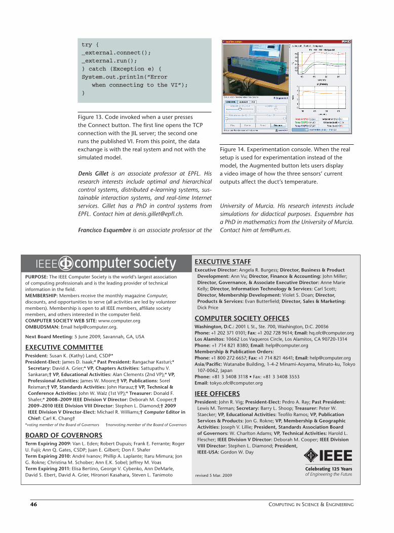
Figure 14. Experimentation console. When the real setup is used for experimentation instead of the model, the Augmented button lets users display a video image of how the three sensors’ current outputs affect the duct’s temperature.
PURPOSE: The IEEE Computer Society is the world’s largest association of computing professionals and is the leading provider of technical information in the field.MEMBERSHIP: Members receive the monthly magazine Computer, discounts, and opportunities to serve (all activities are led by volunteer members). Membership is open to all IEEE members, affiliate society members, and others interested in the computer field.COMPUTER SOCIETY WEB SITE: www.computer.orgOMBUDSMAN: Email [email protected].
Next Board Meeting: 5 June 2009, Savannah, GA, USA
EXECUTIVE COMMITTEEPresident: Susan K. (Kathy) Land, CSDP*President-Elect: James D. Isaak;* Past President: Rangachar Kasturi;* Secretary: David A. Grier;* VP, Chapters Activities: Sattupathu V. Sankaran;† VP, Educational Activities: Alan Clements (2nd VP);* VP, Professional Activities: James W. Moore;† VP, Publications: Sorel Reisman;† VP, Standards Activities: John Harauz;† VP, Technical & Conference Activities: John W. Walz (1st VP);* Treasurer: Donald F. Shafer;* 2008–2009 IEEE Division V Director: Deborah M. Cooper;† 2009–2010 IEEE Division VIII Director: Stephen L. Diamond;† 2009 IEEE Division V Director-Elect: Michael R. Williams;† Computer Editor in Chief: Carl K. Chang†
*voting member of the Board of Governors †nonvoting member of the Board of Governors
BOARD OF GOVERNORSTerm Expiring 2009: Van L. Eden; Robert Dupuis; Frank E. Ferrante; Roger U. Fujii; Ann Q. Gates, CSDP; Juan E. Gilbert; Don F. ShaferTerm Expiring 2010: André Ivanov; Phillip A. Laplante; Itaru Mimura; Jon G. Rokne; Christina M. Schober; Ann E.K. Sobel; Jeffrey M. VoasTerm Expiring 2011: Elisa Bertino, George V. Cybenko, Ann DeMarle, David S. Ebert, David A. Grier, Hironori Kasahara, Steven L. Tanimoto
EXECUTIVE STAFFExecutive Director: Angela R. Burgess; Director, Business & Product Development: Ann Vu; Director, Finance & Accounting: John Miller; Director, Governance, & Associate Executive Director: Anne Marie Kelly; Director, Information Technology & Services: Carl Scott; Director, Membership Development: Violet S. Doan; Director, Products & Services: Evan Butterfield; Director, Sales & Marketing: Dick Price
COMPUTER SOCIETY OFFICESWashington, D.C.: 2001 L St., Ste. 700, Washington, D.C. 20036Phone: +1 202 371 0101; Fax: +1 202 728 9614; Email: [email protected] Alamitos: 10662 Los Vaqueros Circle, Los Alamitos, CA 90720-1314Phone: +1 714 821 8380; Email: [email protected] & Publication Orders: Phone: +1 800 272 6657; Fax: +1 714 821 4641; Email: [email protected]/Pacific: Watanabe Building, 1-4-2 Minami-Aoyama, Minato-ku, Tokyo 107-0062, Japan
Phone: +81 3 3408 3118 • Fax: +81 3 3408 3553Email: [email protected]
IEEE OFFICERSPresident: John R. Vig; President-Elect: Pedro A. Ray; Past President: Lewis M. Terman; Secretary: Barry L. Shoop; Treasurer: Peter W. Staecker; VP, Educational Activities: Teofilo Ramos; VP, Publication Services & Products: Jon G. Rokne; VP, Membership & Geographic Activities: Joseph V. Lillie; President, Standards Association Board of Governors: W. Charlton Adams; VP, Technical Activities: Harold L. Flescher; IEEE Division V Director: Deborah M. Cooper; IEEE Division VIII Director: Stephen L. Diamond; President, IEEE-USA: Gordon W. Day
revised 5 Mar. 2009
Authorized licensed use limited to: EPFL LAUSANNE. Downloaded on May 25, 2009 at 09:10 from IEEE Xplore. Restrictions apply.