Embed Size (px)
Citation preview
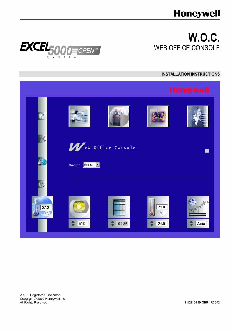
W.O.C. WEB OFFICE CONSOLE
INSTALLATION INSTRUCTIONS
® U.S. Registered Trademark Copyright © 2002 Honeywell Inc. All Rights Reserved EN2B-0219 GE51 R0902


W.O.C. INSTALLATION INSTRUCTIONS CONTENTS
Software Licence Advisory This document supports software that is proprietary to Honeywell Inc. and/or to third
party software vendors. Before software delivery, the end user must execute a software licence agreement that governs software use. Software licence agreement provisions include limiting use of the software to equipment furnished, limiting copying, preserving confidentiality, and prohibiting transfer to a third party. Disclosure, use, or reproduction beyond that permitted in the licence agreement is prohibited.
Trademark Information Windows 2000 is a trademark of Microsoft Corporation and registered in the United States and other countries.
Echelon, LON, LonMark, LonWorks, LonBuilder, NodeBuilder, LonManager,
LonTalk, LonUsers, LonPoint, Neuron, 3120, 3150, the Echelon logo, the LONMARK logo, and the LonUsers logo are trademarks of Echelon Corporation registered in the United States and other countries. LonLink, LonResponse, LonSupport, and LonMaker are trademarks of Echelon Corporation.
EN2B-0219 GE51 R0902


W.O.C. INSTALLATION INSTRUCTIONS CONTENTS
CONTENTS
SYSTEM REQUIREMENTS ........................................................................................................................... 3
GENERAL ........................................................................................................................... 3
INSTALLATION STEPS ........................................................................................................................... 5
PRE-CAUTIONARY MEASURE IN CASE OF POWER FAILURE ........................................................................................ 5
CONNECT TO LAN ........................................................................................................................... 7 Accessibility Test ............................................................................................... 10
INSTALL LON INTERFACE ........................................................................................................................... 10
INSTALL W.O.C. ........................................................................................................................... 14
REGISTER EXCELON ........................................................................................................................... 17 Terminate Excelon Licence................................................................................ 19
START EXCELON ........................................................................................................................... 19 Define Settings .................................................................................................. 22 Working on Domains ......................................................................................... 23
Start New Excelon Session using Same or Different Domain ....................... 23 Create Additional Domain ............................................................................. 25 Switch between Domains.............................................................................. 26
Load Nodes from the Network ........................................................................... 26 Create Map File ................................................................................................. 28
Add Room..................................................................................................... 30 Map NVs to Room Datapoints....................................................................... 31 Add Group..................................................................................................... 32 Smart Global Functions................................................................................. 35 Unmap NVs................................................................................................... 35 Edit Room/Group Names .............................................................................. 36 Delete Room/Group ...................................................................................... 36
Edit Map File...................................................................................................... 36 Load Map File .................................................................................................... 37 Change Network Variable Value........................................................................ 38 Exit Excelon ....................................................................................................... 38 Further Node Functions ..................................................................................... 39
Display Network Variables ............................................................................ 39 Manually Add a Node.................................................................................... 40 View Node Properties ................................................................................... 41 Clear Statistics .............................................................................................. 44 Rename Node............................................................................................... 44 Remove Node ............................................................................................... 44 Re-Read Node .............................................................................................. 44 Reset Node ................................................................................................... 44 Download Application ................................................................................... 44 Send Service Pin .......................................................................................... 46 Send Wink..................................................................................................... 46
Further Network Variable Functions .................................................................. 46 Sort Network Variables ................................................................................. 46 Poll Network Variables .................................................................................. 46 Disable Polling of Network Variables ............................................................ 47 Change Network Variable Value ................................................................... 47 View Configuration Details of Network Variable............................................ 47 Remove Network Variables from NV-Browser .............................................. 48 Clear List....................................................................................................... 48 Reload List View Objects .............................................................................. 48 Hide Colums of Network Variables List ......................................................... 48 Redisplay Hidden Colums of Network Variables List .................................... 49
1 EN2B-0219 GE51 R0902

CONTENTS W.O.C. INSTALLATION INSTRUCTIONS
Menus................................................................................................................ 49
File................................................................................................................ 49 View.............................................................................................................. 49 Lon................................................................................................................ 49 Web .............................................................................................................. 50 ? ................................................................................................................. 50
Context Menu .................................................................................................... 50 Toolbar .............................................................................................................. 51
W.O.C. OPERATION .......................................................................................................................... 52 Prerequisites...................................................................................................... 52 Start W.O.C. ...................................................................................................... 52 Important Steps before Hand-Over to the Room User....................................... 53 Create Multiple Rooms with Identical Room Configuration Data ....................... 54 Software Updates .............................................................................................. 56
LOCAL LANGUAGE VERSIONS .......................................................................................................................... 56
FREQUENTLY ASKED QUESTIONS .......................................................................................................................... 58 Interoperation with occupancy sensors ............................................................. 58
TROUBLESHOOTING .......................................................................................................................... 59
INDEX .......................................................................................................................... 62
EN2B-0219 GE51 R0902 2
W.O.C. INSTALLATION INSTRUCTIONS SYSTEM REQUIREMENTS / GENERAL
SYSTEM REQUIREMENTS Web Office Console PC (Server)
Hardware • Pentium PC 400 MHz or compatible • 64 MB RAM • 1 GB free disk space (for Windows 2000) • PC-LON Interface PCLTA-10 FT-10, Model 73401 or PCLTA-20 PCI • Ethernet LAN connection (card) Software • Microsoft Windows 2000 • Microsoft Internet Explorer 5.0 or higher
Room User PC (Client)
Software • Microsoft Internet Explorer 5.0 or higher
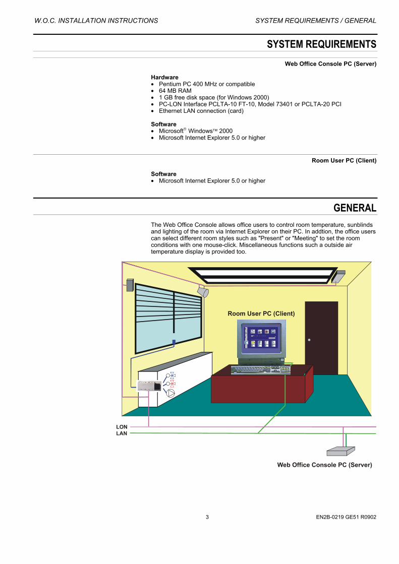
GENERAL The Web Office Console allows office users to control room temperature, sunblinds and lighting of the room via Internet Explorer on their PC. In addtion, the office users can select different room styles such as "Present" or "Meeting" to set the room conditions with one mouse-click. Miscellaneous functions such a outside air temperature display is provided too.
3 EN2B-0219 GE51 R0902
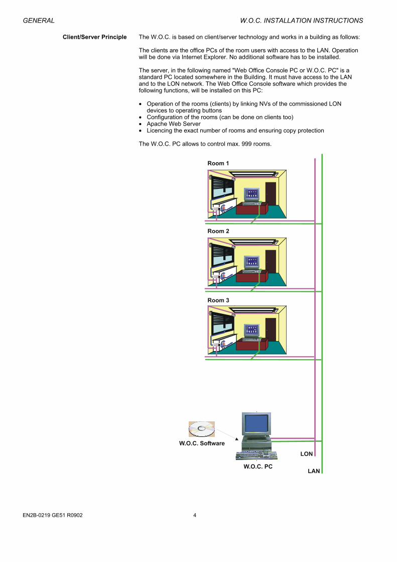
GENERAL W.O.C. INSTALLATION INSTRUCTIONS Client/Server Principle The W.O.C. is based on client/server technology and works in a building as follows:
The clients are the office PCs of the room users with access to the LAN. Operation will be done via Internet Explorer. No additional software has to be installed. The server, in the following named "Web Office Console PC or W.O.C. PC" is a standard PC located somewhere in the Building. It must have access to the LAN and to the LON network. The Web Office Console software which provides the following functions, will be installed on this PC: • Operation of the rooms (clients) by linking NVs of the commissioned LON
devices to operating buttons • Configuration of the rooms (can be done on clients too) • Apache Web Server • Licencing the exact number of rooms and ensuring copy protection The W.O.C. PC allows to control max. 999 rooms.
EN2B-0219 GE51 R0902 4

W.O.C. INSTALLATION INSTRUCTIONS INSTALLATION STEPS / PRE-CAUTIONARY MEASURE ...
Interoperability The W.O.C. software can operate any LonMark control system for room temperature, lighting and sunblind control. The following SNVTs are used:
FUNCTION ROOM DATAPOINT NAME SNVT TemperatureCmd (command) SNVT_temp_p TemperatureAct (status) SNVT_temp_p FanSpeedCmd (command) SNVT_switch FanSpeedAct (status) SNVT_switch OccupancyCmd (command) SNVT_occupancy
Room temperature
OccupancyAct (status) SNVT_occupancy SunblindCmd (command) SNVT_setting Sunblind SunblndAct (status) SNVT_setting LightCmd (command) SNVT_switch Lighting LightAct (status) SNVT_switch
Global Info OutsideAirTemp SNVT_temp_p
Prerequisites Before installing W.O.C. software, the following prerequisites must be given: • Commissioning of LON devices • Overview of temperature, light and sunblind nodes per room • W.O.C. PC has Windows 2000 installed and LAN and LON network connection • IP address, mask and gateway-no. for W.O.C. PC are available • Clients have Internet Explorer 5.0 or higher installed and LAN connection
Operation via Internet The room operation can optionally be performed from the internet if the network administrator has granted access to the corresponding rooms through the firewall.
INSTALLATION STEPS 1. Pre-cautionary Measure in Case of Power Failure 2. Connect to LAN 3. Install LON Interface 4. Install W.O.C. 5. Register Excelon 6. Start Excelon 7. Define Settings 8. Load Nodes from the Network 9. Create Map File 10. W.O.C. Operation 11. Further Node functions (optional)
NOTE: The installation steps refer to a wide range of functions to be carried out
with different software, with Windows system software and partly with software compounds of the W.O.C. software package. These steps will be found in sections completely describing the corresponding software and are therefore not necessarily listed in subsequent sections.
PRE-CAUTIONARY MEASURE IN CASE OF POWER FAILURE IMPORTANT
In case of power failure of the W.O.C. PC, the complete room operation will be impossible.
As a pre-cautionary measure in case of power failure, it is strongly recommended to ensure that the Web Office Console PC is capable to reboot automatically. If this should not be possible, the system needs to be restarted manually.
5 EN2B-0219 GE51 R0902

PRE-CAUTIONARY MEASURE ... W.O.C. INSTALLATION INSTRUCTIONS
Depending on the PC used as Web Office Console PC the steps to set the BIOS into Autoreboot Mode are different. Therefore, please refer to the corresponding PC documentation. NOTE: The person who is configuring the Web Office Console PC must have
Administrator rights.
Procedure 1. Set BIOS into Autoreboot Mode and disable the "BIOS Keyboard Error" option as described in the corresponding PC documentation.
NOTE: If the PC is operated without a keyboard, it will not autoreboot after
powerfailure, unless the "BIOS Keyboard Error" option is disabled. 2. From Windows "Start" menu, select "Run"
RESULT: The "Run" dialog box displays.
3. In the "Run" dialog box, enter "regedit" and click the "OK" button.
RESULT: The "Registry Editor" displays.
EN2B-0219 GE51 R0902 6

W.O.C. INSTALLATION INSTRUCTIONS CONNECT TO LAN
4. Within the Registry Editor, choose the following path:
"HKEY_LOCAL_MACHINE\SOFTWARE\\Microsoft\WindowsNT\ CurrentVersion\Winlogon"
5. Change the following entries in the "Winlogon" directory as follows: AutoAdminLogon = "1" DefaultPassword = "woc" DefaultUserName = "user"
NOTE: "Woc" and "user" are examples. Enter appropriate values. Normally the administrator data is entered. But it is also possible to create a different username and password.
6. Quit the Registry Editor. 7. Continue with connecting the W.O.C. PC to the LAN as described in the
CONNECT TO LAN section on this page .
CONNECT TO LAN To connect to the LAN, a fixed IP address, the mask and the gateway must be set. Ask your network administrator for data. NOTE: It is also possible to connect to the LAN via name listed on a name server.
Procedure 1. From Windows "Start" menu, select "Settings, then "Network and Dial-up
Connections".
RESULT: The "Network and Dial-up Connections" window is displayed.
7 EN2B-0219 GE51 R0902

CONNECT TO LAN W.O.C. INSTALLATION INSTRUCTIONS
2. In the list, double-click on "Local Area Connection".
RESULT: The "Local Area Connection Status" dialog box displays.
3. Click the "Properties button".
RESULT: The "Local Area Connection Properties" dialog box displays.
EN2B-0219 GE51 R0902 8

W.O.C. INSTALLATION INSTRUCTIONS CONNECT TO LAN
4. Check the "Internet Protocol (TCP/IP)" check box and click the "Properties"
button.
RESULT: The "Internet Protocol (TCP/IP) Properties" dialog box displays.
5. Select the "Use the following IP address" radio button.
9 EN2B-0219 GE51 R0902

INSTALL LON INTERFACE W.O.C. INSTALLATION INSTRUCTIONS
6. Enter the values for IP address, subnet mask and Default gateway. 7. Confirm by clicking the "OK" button. 8. Continue with the accessiblity test as described in the ACCESSIBILITY TEST
section on this page.
Accessibility Test With the "Ping" command it can be tested, whether the Web Office Console PC is accessible from any other PC connected to the LAN.
Procedure 1. Open Windows "Command Prompt" on a PC connected to the LAN, but not on
the Web Office Console PC. Example:
2. Enter the IP address of the Web Office Console PC. 3. Check the reply. 4. Continue with installing the LON interface as described in the INSTALL LON
INTERFACE section on this page.
INSTALL LON INTERFACE The following LON interfaces can be used: • LonWorks PCLTA-10/FT-10, Model 73401 for ISA • LonWorks PCLTA-20/FT-10 for PCI The following procedure refers to the LonWorks PCLTA-10/FT-10 / PCLTA-20/FT-10 devices.
IMPORTANT
Install the driver for the LON device before the installation of the board.
EN2B-0219 GE51 R0902 10

W.O.C. INSTALLATION INSTRUCTIONS INSTALL LON INTERFACE
Procedure (Software) 1. Install the LonWorks PCLTA device driver from the Echelon CD provided with the device.
2. After the installation is finished, shut down the PC.
Procedure (Hardware) 1. Insert the LonWorks PCLTA device into the half-size ISA and PCI slot
respectively. Testprocedure 1. Reboot the PC. 2. From Windows "Start" menu, select "Settings, then "Control Panel".
RESULT: The "Control Panel" window displays.
11 EN2B-0219 GE51 R0902

INSTALL LON INTERFACE W.O.C. INSTALLATION INSTRUCTIONS
3. Double-click on "LonWorks Plug´n Play".
RESULT: The "LonWorks Plug´n Play" dialog box displays.
EN2B-0219 GE51 R0902 12
W.O.C. INSTALLATION INSTRUCTIONS INSTALL LON INTERFACE
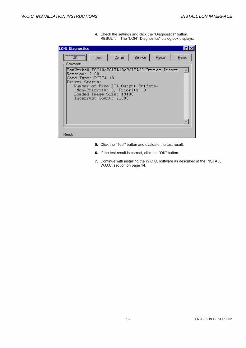
4. Check the settings and click the "Diagnostics" button.
RESULT: The "LON1 Diagnositcs" dialog box displays.
5. Click the "Test" button and evaluate the test result. 6. If the test result is correct, click the "OK" button.
7. Continue with installing the W.O.C. software as described in the INSTALL
W.O.C. section on page 14.
13 EN2B-0219 GE51 R0902
INSTALL W.O.C. W.O.C. INSTALLATION INSTRUCTIONS
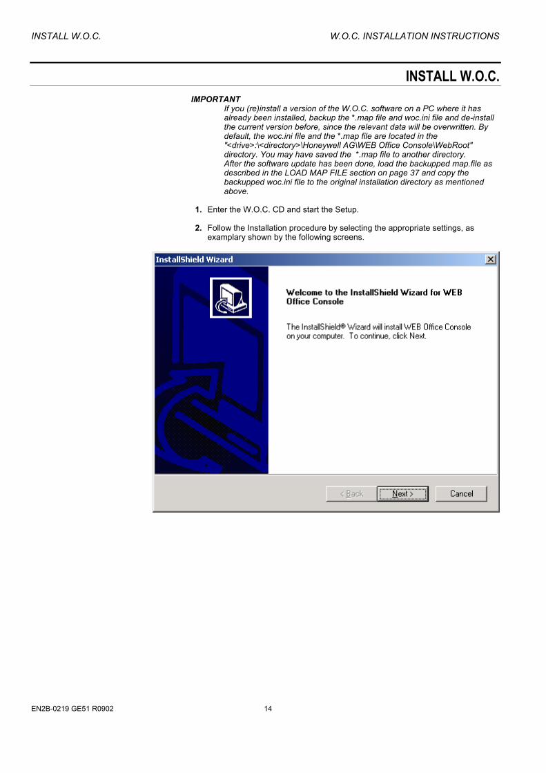
INSTALL W.O.C. IMPORTANT
If you (re)install a version of the W.O.C. software on a PC where it has already been installed, backup the *.map file and woc.ini file and de-install the current version before, since the relevant data will be overwritten. By default, the woc.ini file and the *.map file are located in the "<drive>:\<directory>\Honeywell AG\WEB Office Console\WebRoot" directory. You may have saved the *.map file to another directory. After the software update has been done, load the backupped map.file as described in the LOAD MAP FILE section on page 37 and copy the backupped woc.ini file to the original installation directory as mentioned above.
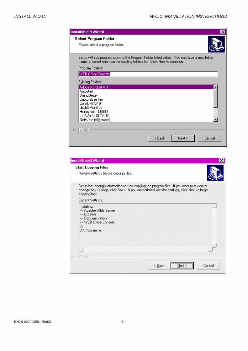
1. Enter the W.O.C. CD and start the Setup. 2. Follow the Installation procedure by selecting the appropriate settings, as
examplary shown by the following screens.
EN2B-0219 GE51 R0902 14

W.O.C. INSTALLATION INSTRUCTIONS INSTALL W.O.C.
15 EN2B-0219 GE51 R0902
INSTALL W.O.C. W.O.C. INSTALLATION INSTRUCTIONS
EN2B-0219 GE51 R0902 16

W.O.C. INSTALLATION INSTRUCTIONS REGISTER EXCELON
3. Restart the W.O.C. PC.
4. Continue with starting Excelon as described in the START EXCELON section
on page 19.
REGISTER EXCELON Procedure 1. If the "Registration" dialog box in Excelon is not already open, click on "Help"
menu, then submenu item "Registration".
RESULT: The "Excelon Registration" dialog box displays.
17 EN2B-0219 GE51 R0902

REGISTER EXCELON W.O.C. INSTALLATION INSTRUCTIONS
2. Click on the "Registration" tab.
On the "Registration" tab, a reference code is displayed, which is generated
from internal PC data during installation of Excelon. 3. In the "Licence Key" field, enter the licence key you have received from
Honeywell (Refer to Release Bulletin for Ordering Procedure).
4. Click on the "Register Key" button.
RESULT: The licence key gets hidden in the field of the same name. 5. Click on the "Licence Key" Info tab.
EN2B-0219 GE51 R0902 18

W.O.C. INSTALLATION INSTRUCTIONS START EXCELON
RESULT: You are now registered. The expiration date is set as requested and the features displayed in the list are available.
6. Click on the "Close" button.
Terminate Excelon Licence Purpose To terminate the Excelon licence to use on another PC (different or new one).
When ordering Excelon you have got a unique voucher from Honeywell. With the unique voucher number you were allowed to get a licence key during the registration procedure on the Honeywell Web Server. When terminating the licence you need to get a new licence key from the Honeywell Web Server for using Excelon on another PC. You can also give back your licence.
START EXCELON Prerequisites The LON network interface driver, e.g. LonWorks PCLTA-20/FT-10 for PCI must be
running. Procedure 1. Start Excelon from the corresponding program group in the Windows "Start"
menu.
RESULT: If Excelon is not licenced yet, a message shows that it is currently running in evaluation mode. To get registered, click "OK" button. For further information about the registration process, refer to the REGISTER EXCELON section on page 17.
If a connection to LonWorks has not been established yet, the
"Excelon Network Interface Settings" dialog box displays.
If Excelon is already registered, the "Excelon Network Interface Settings" box is active and can be opened in the Windows taskbar by clicking on the correponding icon.
19 EN2B-0219 GE51 R0902
START EXCELON W.O.C. INSTALLATION INSTRUCTIONS
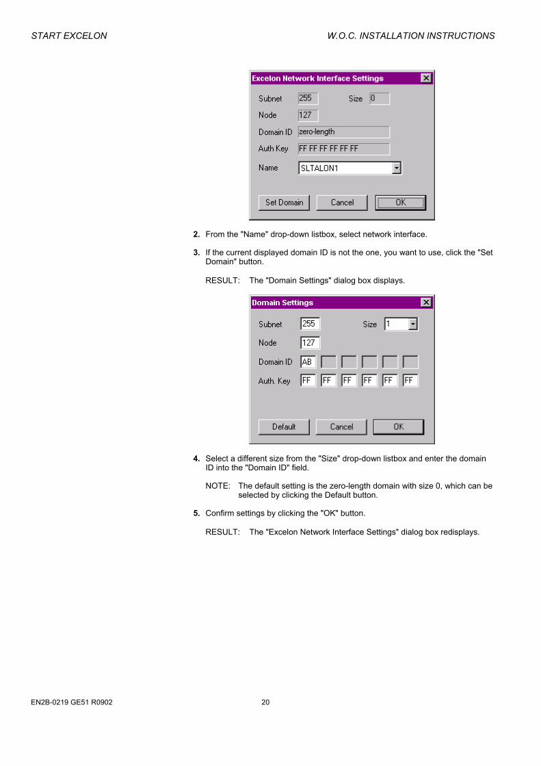
2. From the "Name" drop-down listbox, select network interface. 3. If the current displayed domain ID is not the one, you want to use, click the "Set
Domain" button. RESULT: The "Domain Settings" dialog box displays.
4. Select a different size from the "Size" drop-down listbox and enter the domain ID into the "Domain ID" field.
NOTE: The default setting is the zero-length domain with size 0, which can be
selected by clicking the Default button. 5. Confirm settings by clicking the "OK" button.
RESULT: The "Excelon Network Interface Settings" dialog box redisplays.
EN2B-0219 GE51 R0902 20
W.O.C. INSTALLATION INSTRUCTIONS START EXCELON
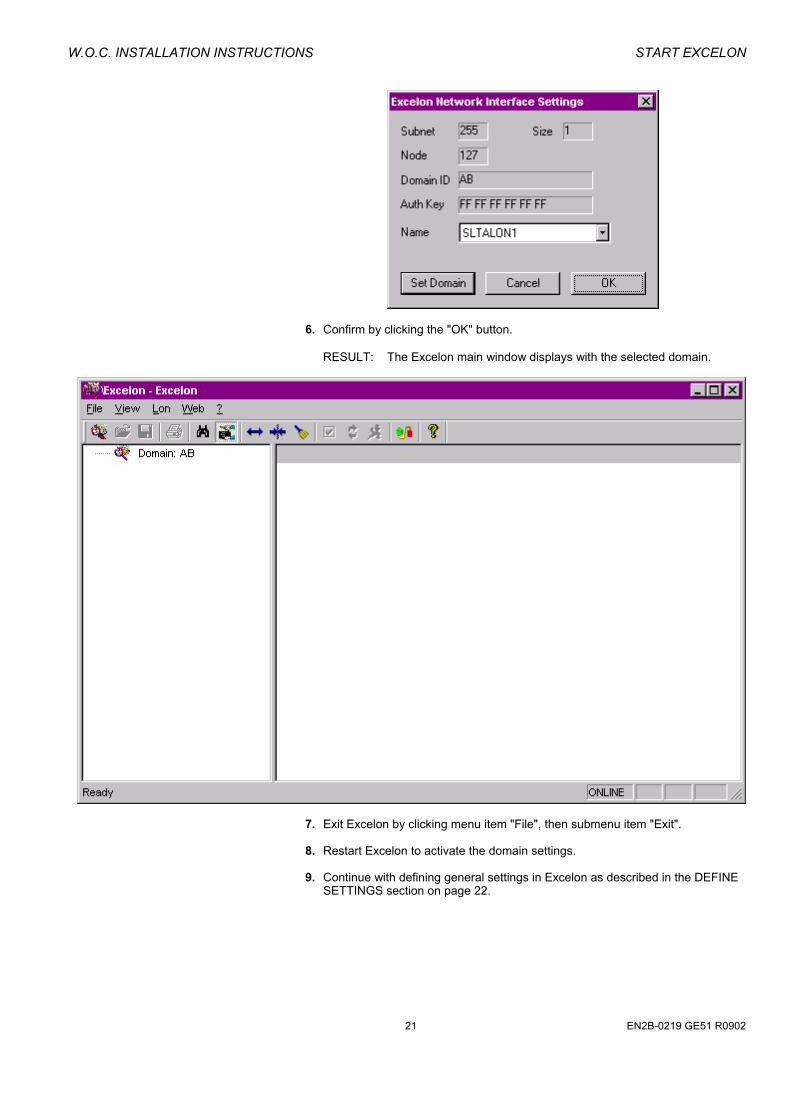
6. Confirm by clicking the "OK" button.
RESULT: The Excelon main window displays with the selected domain.
7. Exit Excelon by clicking menu item "File", then submenu item "Exit". 8. Restart Excelon to activate the domain settings. 9. Continue with defining general settings in Excelon as described in the DEFINE
SETTINGS section on page 22.
21 EN2B-0219 GE51 R0902

START EXCELON W.O.C. INSTALLATION INSTRUCTIONS
Define Settings To meet your requirements optimumly when working with Excelon, you should note the general settings defined.
Procedure 1. Select menu item "Lon", then submenu item "Settings".
RESULT: The "Excelon Settings" dialog box displays.
2. Click the "Default" button to set defaults and/or check desired options under: Load Node on Service Pin If checked, the node will be loaded and displayed in the tree after the service
pin at the device has been pushed. Highlight Node on Service Pin If checked, the node in the tree will be highlighted after the service pin at the
device has been pushed. Load Room Mapping on Startup !!! This must be enabled in order to ensure uninterupted operation of the WOC
after power fail of the WOC server PC !!! If checked, only those nodes will be loaded on Startup, for which room
mappings have already been done. Scan Lon Network on Startup If checked, the network will be scanned automatically on Startup. Note, that
Excelon scans only the domain set for the network interface and in addition the zero-length domain, if the "Search nodes also zero-domain option" is checked.
Minimize Window on Startup If checked, the Excelon main window will be minimized on Startup. Search nodes also on zero-domain If checked, nodes will also been searched on zero-length domain, even if
current network interface is set to another domain. Show extended address info in NV Browser If checked, for bound NVs the extended address and service info (address table
entries) will be displayed in the NV Browser
EN2B-0219 GE51 R0902 22
W.O.C. INSTALLATION INSTRUCTIONS START EXCELON
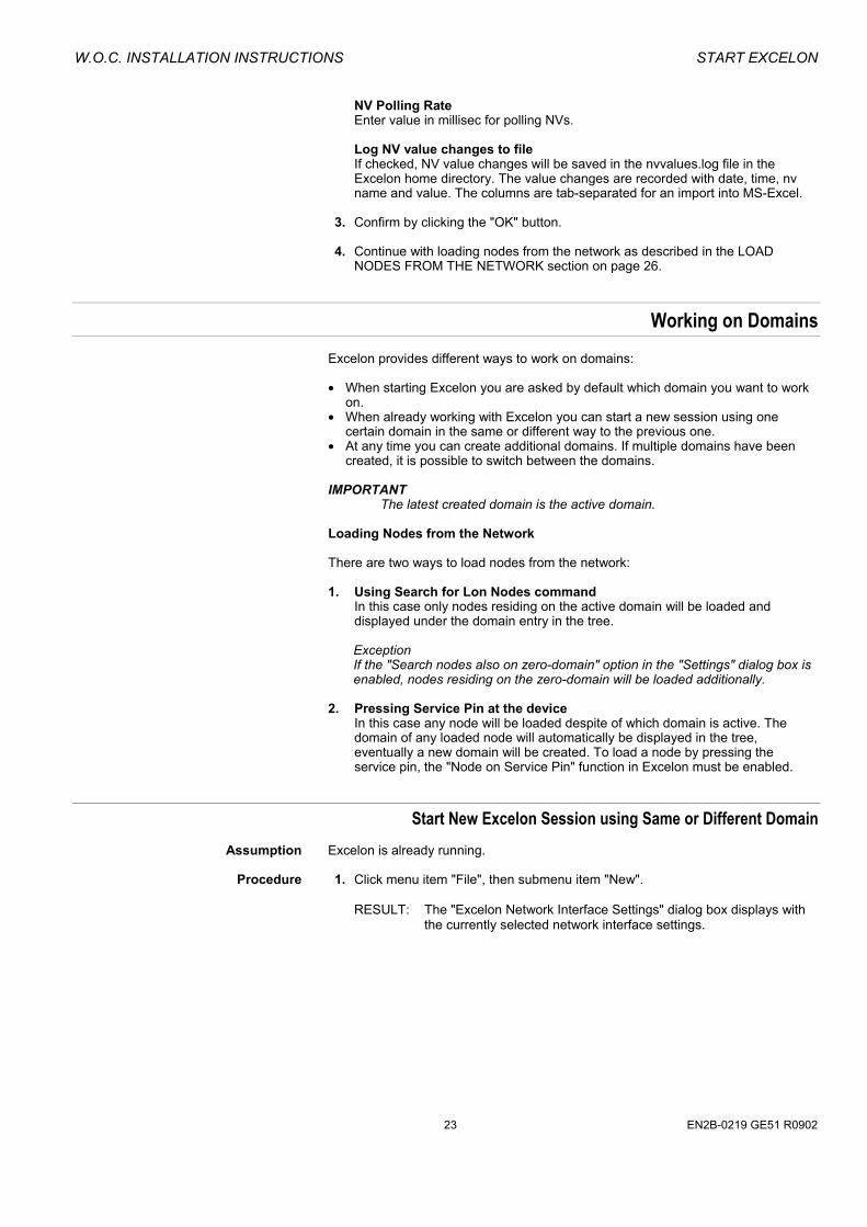
NV Polling Rate Enter value in millisec for polling NVs. Log NV value changes to file If checked, NV value changes will be saved in the nvvalues.log file in the
Excelon home directory. The value changes are recorded with date, time, nv name and value. The columns are tab-separated for an import into MS-Excel.
3. Confirm by clicking the "OK" button. 4. Continue with loading nodes from the network as described in the LOAD
NODES FROM THE NETWORK section on page 26.
Working on Domains Excelon provides different ways to work on domains: • When starting Excelon you are asked by default which domain you want to work
on. • When already working with Excelon you can start a new session using one
certain domain in the same or different way to the previous one. • At any time you can create additional domains. If multiple domains have been
created, it is possible to switch between the domains. IMPORTANT
The latest created domain is the active domain. Loading Nodes from the Network
There are two ways to load nodes from the network: 1. Using Search for Lon Nodes command
In this case only nodes residing on the active domain will be loaded and displayed under the domain entry in the tree.
Exception If the "Search nodes also on zero-domain" option in the "Settings" dialog box is enabled, nodes residing on the zero-domain will be loaded additionally.
2. Pressing Service Pin at the device
In this case any node will be loaded despite of which domain is active. The domain of any loaded node will automatically be displayed in the tree, eventually a new domain will be created. To load a node by pressing the service pin, the "Node on Service Pin" function in Excelon must be enabled.
Start New Excelon Session using Same or Different Domain Assumption Excelon is already running. Procedure 1. Click menu item "File", then submenu item "New".
RESULT: The "Excelon Network Interface Settings" dialog box displays with
the currently selected network interface settings.
23 EN2B-0219 GE51 R0902

START EXCELON W.O.C. INSTALLATION INSTRUCTIONS
2. If the current displayed domain ID is not the one, you want to use, click on the
"Set Domain" button. RESULT: The "Domain Settings" dialog box displays.
3. Select different size from the "Size" drop-down listbox and enter the domain ID into the "Domain ID" field.
NOTE: The default setting is the zero-length domain with size 0, which can be
selected by clicking the "Default" button.
4. Confirm settings by clicking the "OK" button.
RESULT: The "Excelon Network Interface Settings" dialog box redisplays.
5. Confirm by clicking the "OK" the button.
RESULT: The selected domain is displayed in the tree of the Excelon main
window.
EN2B-0219 GE51 R0902 24
W.O.C. INSTALLATION INSTRUCTIONS START EXCELON
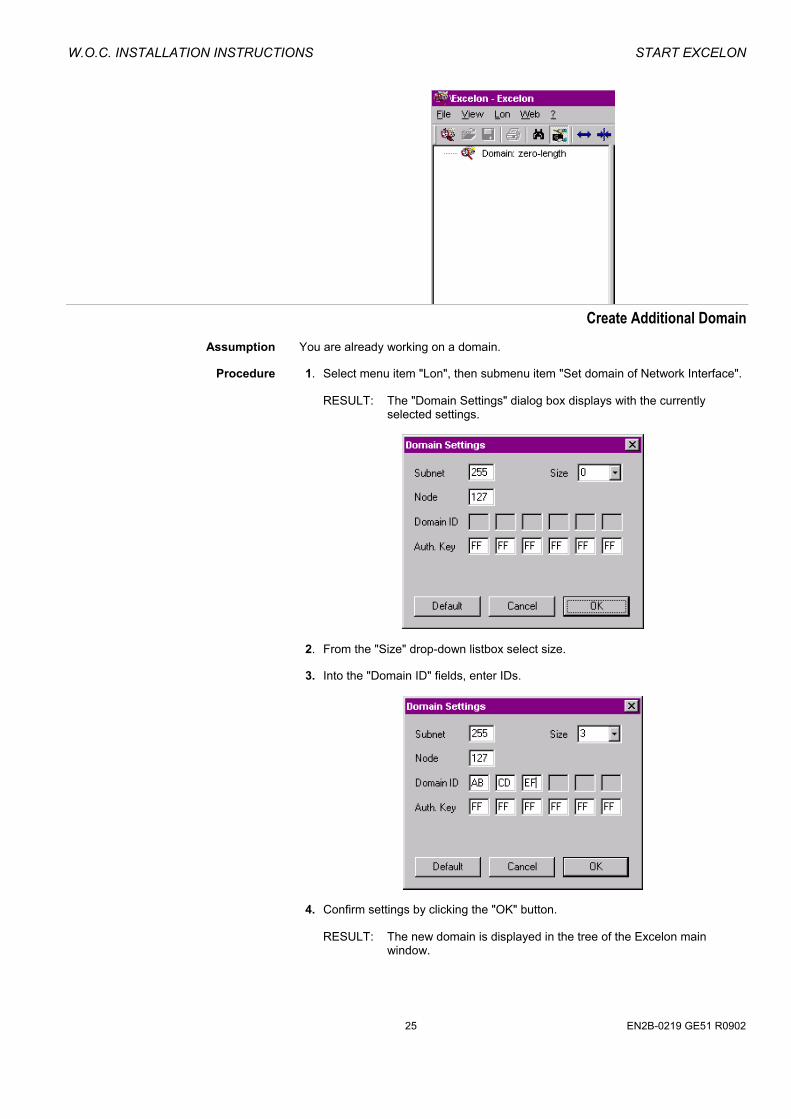
Create Additional Domain
Assumption You are already working on a domain. Procedure 1. Select menu item "Lon", then submenu item "Set domain of Network Interface".
RESULT: The "Domain Settings" dialog box displays with the currently selected settings.
2. From the "Size" drop-down listbox select size. 3. Into the "Domain ID" fields, enter IDs.
4. Confirm settings by clicking the "OK" button.
RESULT: The new domain is displayed in the tree of the Excelon main window.
25 EN2B-0219 GE51 R0902
START EXCELON W.O.C. INSTALLATION INSTRUCTIONS
IMPORTANT
The latest created domain is the active domain. When searching for nodes on the network via the "Search for Lon nodes" command only nodes residing on the active domain will be loaded, except if the "Search nodes also on zero-domain" option in the "Settings" dialog box is enabled. In this case, nodes residing on the zero-domain will be loaded additionally. The loaded nodes will be arranged under the corresponding domain entries in the tree.
To work on another domain, refer to the SWITCH BETWEEN DOMAINS section on this page.
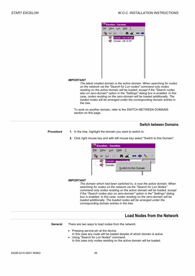
Switch between Domains Procedure 1. In the tree, highlight the domain you want to switch to. 2. Click right mouse key and with left mouse key select "Switch to this Domain".
IMPORTANT
The domain which had been switched to, is now the active domain. When searching for nodes on the network via the "Search for Lon Nodes" command only nodes residing on the active domain will be loaded, except if the "Search nodes also on zero-domain" option in the" Settings" dialog box is enabled. In this case, nodes residing on the zero-domain will be loaded additionally. The loaded nodes will be arranged under the corresponding domain entries in the tree.
Load Nodes from the Network General There are two ways to load nodes from the network:
• Pressing service pin at the device. In this case any node will be loaded despite of which domain is active.
• Using "Search for Lon Nodes" command. In this case only nodes residing on the active domain will be loaded.
EN2B-0219 GE51 R0902 26

W.O.C. INSTALLATION INSTRUCTIONS START EXCELON
NOTE: Define general settings as described in the DEFINE SETTINGS section on
page 22. Please, refer also to the WORKING ON DOMAINS section on page 23.
Procedure 1. To load a node by pressing the service pin, first click the "Load on Service Pin"
icon on the toolbar.
2. At the device(s), press the service pin.
3. To search for nodes on the active domain, note which domain is currently active. If necessary, switch to the desired domain.
4. Select menu item "Lon", then submenu item "Search for Lon Nodes" or click on
the "Search for Lon Nodes" icon on the toolbar.
NOTE If the menu item is inactive, Excelon could not connect to LonWorks. Verify the driver settings and re-start Excelon, or select menu item "File", then submenu item "New".
Please note that if the LON Web Server PC is connected to the
network via LON router, the service pin button of the router has to be pressed.
RESULT: The nodes are loaded and displayed in the tree.
The LON devices and nodes are displayed by the following symbols: Lon Network (root) Host-based controller Neuron-based node, LonMark Neuron-based node, non-LonMark Honeywell XFL521B module
27 EN2B-0219 GE51 R0902

START EXCELON W.O.C. INSTALLATION INSTRUCTIONS
Honeywell XFL522B module Honeywell XFL523B module Honeywell XFL524B module Nodes states are displayed as follows:
configured, online
configured, offline
unconfigured
applicationless
unknown 5. Continue with creating mappings between room datapoints and NVs as
described in the CREATE MAP FILE section on page 28.
Create Map File General To provide the operation for the office user, the LON devices NVs must be mapped
to room datapoints which represent the W.O.C. operating functions. Mapping information will be saved in a map file which can include multiple rooms and global functions. The mapping will be done in the "Web Office Console Room Mapping" dialog box.
In the left tree, all room relevant data will be displayed. Unmapped room datapoints are displayed in grey. Mapped room datapoints will be displayed colorfully.
EN2B-0219 GE51 R0902 28

W.O.C. INSTALLATION INSTRUCTIONS START EXCELON
In the right tree, the controller related network variables are displayed. The "NV Filter" drop-down list box on the bottom allows to choose a filter for displaying particular NVs on the right. Creating mappings includes the following steps performed by the left-handed buttons and the "Map" and "Unmap" buttons in the middle: • Adding rooms • Mapping controller NVs to the corresponding room datapoints • Adding groups for external functions such as outside air temperature
measurement • Creating group datapoints by mapping appropriate NVs to groups • Editing/deleting elements such as rooms, groups and datapoints (optional) The mapping information is automatically saved as map file by clicking the "OK" button. A saved map file can be reloaded via the "Load" button on the left-hand bottom. This is especially important after a W.O.C. software update has been done.
Prerequisites The nodes must have been loaded.
Procedure 1. Click on the "Edit WOC Mappings icon" on the toolbar.
RESULT: The "Web Office Console Room Mapping" dialog box displays.
2. On the left, click the "New button".
RESULT: All mapped rooms currently displayed will be deleted in the tree, as the following message box displays.
29 EN2B-0219 GE51 R0902

START EXCELON W.O.C. INSTALLATION INSTRUCTIONS
NOTE: The mapped rooms will not be deleted physically. But if they have not already been saved as map file, the data will get lost.
3. Click the "Cancel" button, if you first want to save the map file currently
displayed and start with step 2 again. Or, Click the "OK" button to create a new map file.
RESULT: By default a room, e.g. Room1, is added to the tree with 10
unmapped default room datapoints.
4. Continue by adding desired number of rooms, as described in the ADD ROOM
section on this page.
Add Room Depending on the building configuration, add desired numbers of rooms into the tree.
Procedure 1. Click the "Add Room" button.
EN2B-0219 GE51 R0902 30

W.O.C. INSTALLATION INSTRUCTIONS START EXCELON
RESULT: A new room with standard room datapoints is inserted in the left tree.
2. Edit the highlighted name, e.g. Room2, if desired, and press the "Enter" key.
3. Repeat steps 1 and 2 for the desired number of rooms you want to add.
4. Continue by mapping NVs to room datapoints as described in the MAP NVS TO
ROOM DATAPOINTS section on this page.
Map NVs to Room Datapoints Choose NV Filter Before starting to map NVs to room datapoints, it is recommended to select the
appropriate filter from the "NV Filter" drop-down list box on the bottom. Room functions displays all NV-types which fit to the room functions on the left and
can be mapped to appropriate room datapoints. Mappable NVs displays all NV-types that can be mapped either to room datapoints or to global room datapoints. All NV´s and NCi´s displays all mappable NVs and all NCi´s (configuration parameters).
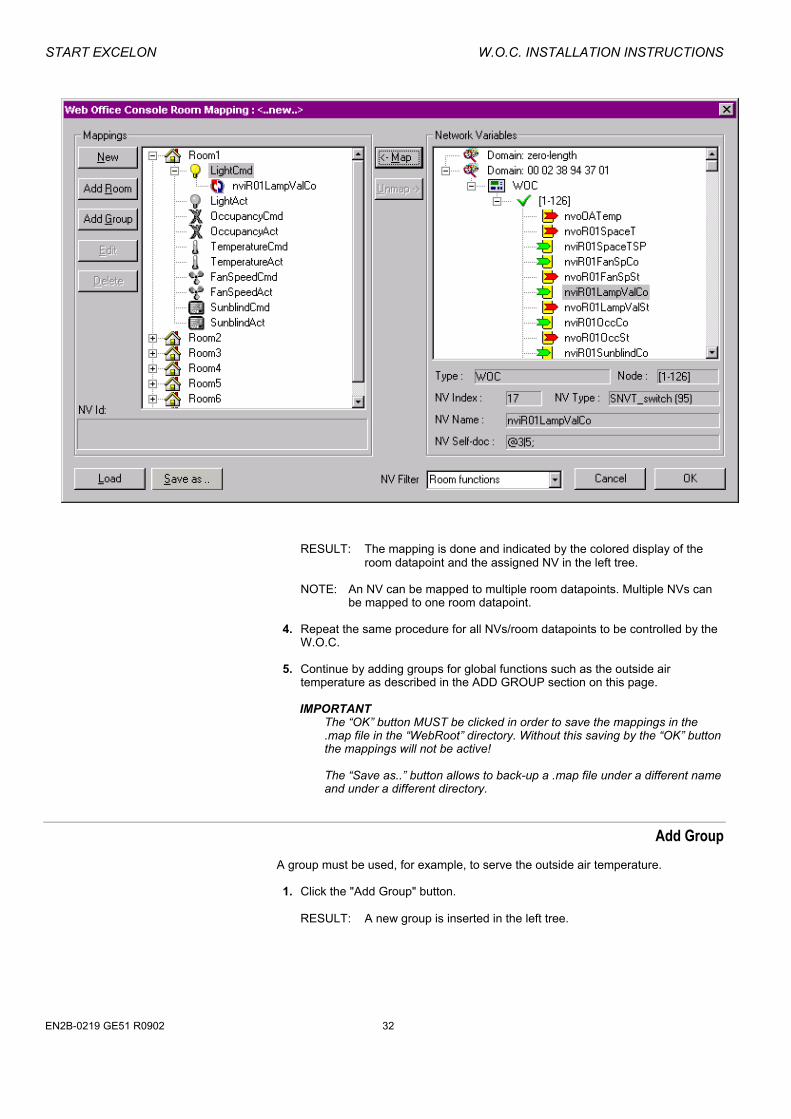
Procedure 1. In the left tree, select greyed room user address, e.g. "LightCmd". 2. In the right tree, select the NV, you want to be mapped to the room user
address. 3. Click the "Map" button.
31 EN2B-0219 GE51 R0902
START EXCELON W.O.C. INSTALLATION INSTRUCTIONS
RESULT: The mapping is done and indicated by the colored display of the room datapoint and the assigned NV in the left tree.
NOTE: An NV can be mapped to multiple room datapoints. Multiple NVs can
be mapped to one room datapoint. 4. Repeat the same procedure for all NVs/room datapoints to be controlled by the
W.O.C. 5. Continue by adding groups for global functions such as the outside air
temperature as described in the ADD GROUP section on this page.
IMPORTANT The “OK” button MUST be clicked in order to save the mappings in the .map file in the “WebRoot” directory. Without this saving by the “OK” button the mappings will not be active! The “Save as..” button allows to back-up a .map file under a different name and under a different directory.
Add Group A group must be used, for example, to serve the outside air temperature.
1. Click the "Add Group" button.
RESULT: A new group is inserted in the left tree.
EN2B-0219 GE51 R0902 32

W.O.C. INSTALLATION INSTRUCTIONS START EXCELON
2. Give the group a functional description, for example, to provide the outside air
temperature, enter "WOCGlobal".
NOTE: To provide the outside air temperature, the group must read "WOCGlobal".
33 EN2B-0219 GE51 R0902

START EXCELON W.O.C. INSTALLATION INSTRUCTIONS
3. To do the mapping, highlight the group name, shift to the right tree, highlight the appropriate NV and click the "Map" button.
4. To provide the outside air temperature, change the assigned NV name to
"OutsideAirTemp".
5. Save the mappings in the .map file by clicking the "OK" button.
RESULT: The "Web Office Console Mapping" dialog box is closed. If the map file was created from scratch and to be saved for the first
time, the language dependent "Save as" Windows dialog box displays.
^x
EN2B-0219 GE51 R0902 34

W.O.C. INSTALLATION INSTRUCTIONS START EXCELON
6. Enter the name for the map file and click the "Save" button.
RESULT: The "Web Office Console Mapping" dialog box is closed.
7. Backup the .map file.
IMPORTANT
If you (re)install a version of the W.O.C. software on a PC where it has already been installed, backup the current *.map file before, because it will be overwritten with an empty one and all mappings will be lost. After the software update has been done, reload the backupped .map file.
8. Continue with the steps described in the W.O.C. OPERATION section on page
52.
Smart Global Functions By mapping all light commands to one datapoint of a special room, e.g. the caretaker room, all lights can be switched Off by one mouse-click.
Unmap NVs Procedure 1. In the left tree of the "Web Office Console Mapping" dialog box, select the NV
you want to unmap.
2. Click the "Unmap" button.
3. Save the map file by clicking the "OK" button.
35 EN2B-0219 GE51 R0902

START EXCELON W.O.C. INSTALLATION INSTRUCTIONS
Edit Room/Group Names Procedure 1. In the "Web Office Console Mapping" dialog box, highlight the room,
respectively the group name in the left tree and click the "Edit" button.
NOTE: NVs which have been mapped to groups can also be edited. 2. Change the name. 3. Save the changed map file by clicking the "OK" button.
Delete Room/Group Procedure 1. In the "Web Office Console Mapping" dialog box, highlight the desired room,
respectively group name in the tree and click the "Delete" button. 2. Save the changed map file by clicking the "OK" button.
Edit Map File The map file can be edited by: • Adding/Deleting rooms and groups • Editing room, group, or mapped NV names (only for groups) • Unmapping NVs and saving it by clicking the “OK” button. For procedures refer to the corresponding sections.
EN2B-0219 GE51 R0902 36

W.O.C. INSTALLATION INSTRUCTIONS START EXCELON
Load Map File Procedure 1. On the bottom of the "Web Office Console Mapping" dialog box, click the "Load"
button.
RESULT: The language dependent "Open" Windows dialog box displays.
2. From the list, select the map file and click the "Open" button.
RESULT: The mapped rooms will be displayed.
37 EN2B-0219 GE51 R0902

START EXCELON W.O.C. INSTALLATION INSTRUCTIONS
Change Network Variable Value 1. In the network variables tree on the right, double-click on the NV you want
display/change the value for.
RESULT: The "NV Update" dialog box displays showing the NV name, NV type, and the currrent value as "normal" value with unit and as raw value in HEX format.
The values can be entered as “normal” value or as raw value and the entered values will be converted.
2. To experiment which raw value corresponds to which normal value, enter the
value into the "Raw" field and click the "Convert" button.
RESULT: The entered value will be converted. 3. If the value is sufficient, click the "NV Update !" button.
RESULT: The updated value is written to the NV and - if Polling is enabled -
instantly displayed in the NV list. An updated NV is indicated by an upward button in the "Poll/Index" column.
Exit Excelon Procedure 1. Click menu item "File", then submenu item "Exit".
EN2B-0219 GE51 R0902 38

W.O.C. INSTALLATION INSTRUCTIONS START EXCELON
Further Node Functions
Display Network Variables 1. In the tree, double-click on the node. Or, select node with right mouse key, and with left mouse key click on "Browse
NV´s".
RESULT: The dedicated network variables are displayed on the right pane.
The network variables are displayed by the following symbols: SNVTs (on yellow background) nvi (green) nvo (red) SCPTs (on yellow background) nci (blue) UNVTs (on grey background) nvi (green) nvo (red) UCPTs (on grey background) nci (blue) The following values/statuses are listed for each network variable:
39 EN2B-0219 GE51 R0902

START EXCELON W.O.C. INSTALLATION INSTRUCTIONS
• Poll/Index
The box before the NV symbol displays the polling status of the NV. If the box is checked, the NV will currently be polled. Value changes are indicated by an upward buttton in the box. The number after the NV symbol shows the index number. If an nvi can not be read from LonWorks, an exclamation mark is displayed in the box.
• Name NV name
• SelfDoc LonMark Selfdoc string
• SNVT NV type, user-defined SNVTs send "_ _ "
• Size Length of the NV in bytes
• Bound Indicates whether the NV is bound or not, shows the NV selector if bound.
• Address Displays address table used for a bound NV
• Service Address Displays service type of a bound NV
• Value Current value of the NV in SNVT format.
• Raw Hex Current value of the NV in HEX format.
Manually Add a Node A node can be added manually by entering the Neuron ID.
Procedure 1. Select menu item "Lon", then submenu item "Manually add a Lon node".
RESULT: The "Add New Node" dialog box displays.
2. Enter the neuron ID separated by hyphens or spaces or non-separated and
click the "OK" button.
EN2B-0219 GE51 R0902 40

W.O.C. INSTALLATION INSTRUCTIONS START EXCELON
View Node Properties Node properties are e.g.: • Program and neuron ID • Selfdoc string • Location string • Neuron chip type • Status (configured/online, unconfigured etc.) • Domain information such as subnet and node number • Address and statistics information
Procedure 1. In the tree, click on the node, you want to display properties for. 2. Click right mouse key, and with left mouse key click on "Properties".
RESULT: The "Node Properties" dialog box displays.
Node
On the "Node" tab, the following data is shown:
Program ID Neuron ID Node Self Doc string Location string Neuron Chip - Firmware For detailed information, please refer to the LONMARK
APPLICATION LAYER INTEROPERABILITY GUIDELINES documentation.
41 EN2B-0219 GE51 R0902
START EXCELON W.O.C. INSTALLATION INSTRUCTIONS
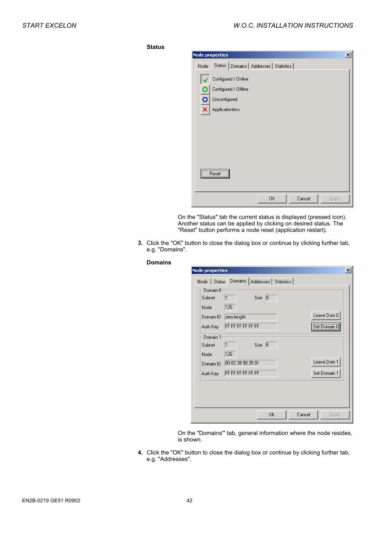
Status
On the "Status" tab the current status is displayed (pressed icon).
Another status can be applied by clicking on desired status. The "Reset" button performs a node reset (application restart).
3. Click the "OK" button to close the dialog box or continue by clicking further tab,
e.g. "Domains".
Domains
On the "Domains'" tab, general information where the node resides,
is shown. 4. Click the "OK" button to close the dialog box or continue by clicking further tab,
e.g. "Addresses".
EN2B-0219 GE51 R0902 42
W.O.C. INSTALLATION INSTRUCTIONS START EXCELON
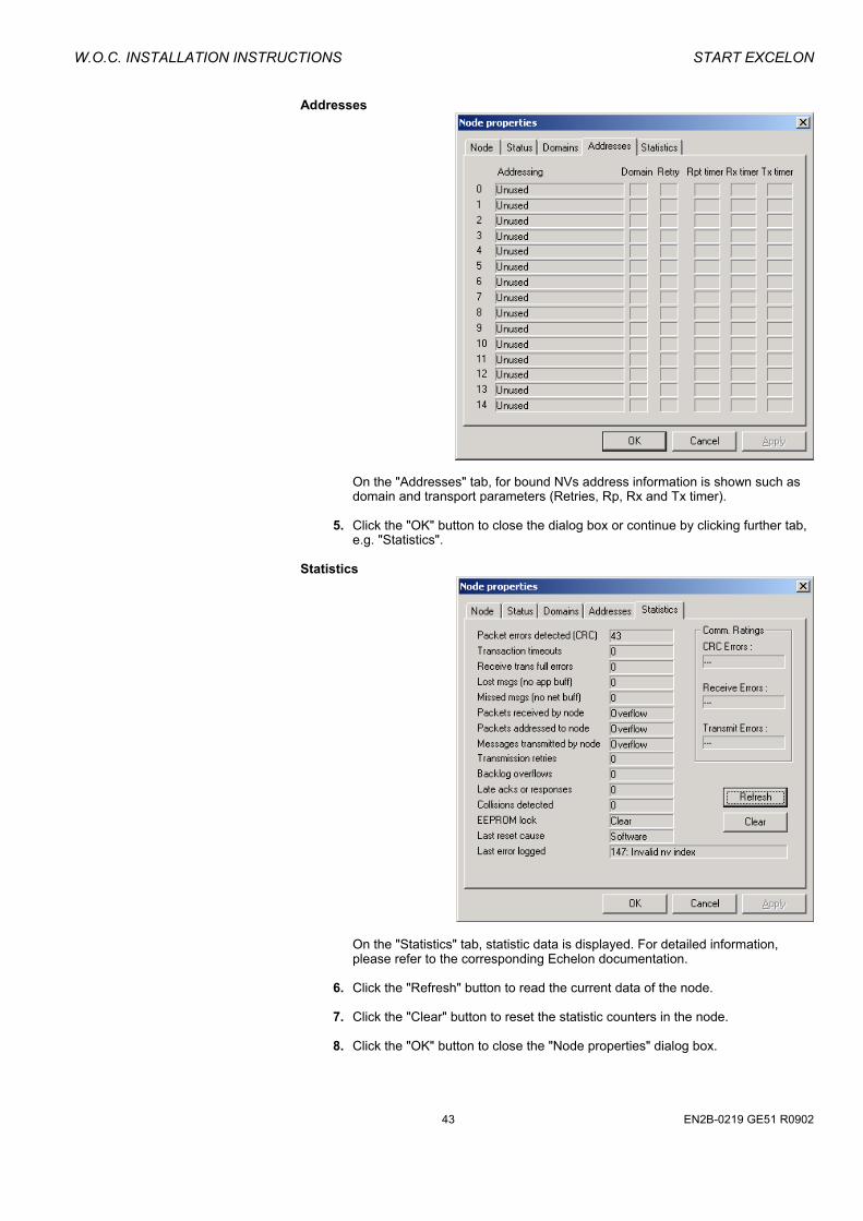
Addresses
On the "Addresses" tab, for bound NVs address information is shown such as
domain and transport parameters (Retries, Rp, Rx and Tx timer). 5. Click the "OK" button to close the dialog box or continue by clicking further tab,
e.g. "Statistics". Statistics
On the "Statistics" tab, statistic data is displayed. For detailed information,
please refer to the corresponding Echelon documentation. 6. Click the "Refresh" button to read the current data of the node. 7. Click the "Clear" button to reset the statistic counters in the node. 8. Click the "OK" button to close the "Node properties" dialog box.
43 EN2B-0219 GE51 R0902

START EXCELON W.O.C. INSTALLATION INSTRUCTIONS
Clear Statistics Procedure 1. In the tree, click on the node, which you want to clear statistics for.
2. Click right mouse key, and with left mouse key click on "Clear Statistics".
RESULT: In the "Node properties" dialog box, the statistics have been cleared.
Rename Node Procedure 1. In the Excelon main window, highlight the node in the tree.
2. Click right mouse key, and with left mouse key click on "Rename".
RESULT: The location string of the node will be changed.
Remove Node Nodes should be removed if the domain table or the location string of a node has been modified, for example, when the HEX switch of an XFL module has been changed. After the node was removed, the node can be add again via the "Search for Lon Nodes" function to display the actual node properties. NOTE: Removing a node has no effect on the node itself.
Procedure 1. In the Excelon main window, highlight the node in the tree. 2. Click right mouse key, and with left mouse key click on "Remove".
Re-Read Node Procedure 1. In the Excelon main window, highlight the node in the tree.
2. Click right mouse key, and with left mouse key click on "Re-Read".
RESULT: The node will be removed from the tree and reloaded.
Reset Node Procedure 1. In the Excelon main window, highlight the node in the tree.
2. Click right mouse key, and with left mouse key click on "Reset".
RESULT: The application in the node will be restarted.
Download Application Procedure 1. In the tree, click on the node, you want to download an application to. 2. Click right mouse key, and with left mouse key click on "Download".
RESULT: The "Node Program Download" dialog box opens showing the program ID, selfdoc string, neuron chip type and firmware of the node.
NOTE: All neuron chip types even with Flash eprom can be downloaded.
EN2B-0219 GE51 R0902 44

W.O.C. INSTALLATION INSTRUCTIONS START EXCELON
3. Click on the "Program" button. 4. In the "Open" dialog box, select the application type. Under "File type", select
the application in the list and confirm by clicking the "OK" button.
NOTE: Note that when downloading an NXE file, the XIF file and the application file must correspond to avoid destruction of the node. Loading an APB file does not require a XIF file.
Downloading is only possible if the chip version matches the firmware
version.
RESULT: The application data is displayed in the "Node Program Download" dialog box.
45 EN2B-0219 GE51 R0902

START EXCELON W.O.C. INSTALLATION INSTRUCTIONS
5. Compare the new application data with the currently running application data displayed at the top of the dialog box.
6. If desired, select options under
• Set node configured, online after download • Load executable program • Load configuration
by checking the corresponding checkbox
7. Confirm by clicking the "Load" button.
RESULT: The new firmware is downloaded.
Send Service Pin Procedure 1. Select menu item "Lon", then submenu item "Send Service Pin".
RESULT: The service pin of the network interface has been sent to the network.
Send Wink Procedure 1. In the Excelon main window, highlight node in the tree.
2. Click right mouse key, and with left mouse key click on "Wink".
RESULT: A wink command has been sent to the selected node.
Further Network Variable Functions
Sort Network Variables NVs can be sorted ascending and descending by index number and by name.
1. To sort NVs by index number, click on the "Poll/Index" column title. 2. To sort NVs by name, click on the "Name" column title.
Poll Network Variables 1. Display NVs as described in the DISPLAY NETWORK VARIABLES section on
page 39. 2. In the "Poll/Index" column, click checkbox at the NV(s).
Or, highlight the NV with left mouse key in the list. To highlight multiple NVs concurrently use STRG, respectively SHIFT key. Click right mouse key and with left mouse key click on "Cyclic Refresh On".
To poll all NVs, click on the "Cyclic Refresh" icon in the toolbar or select menu item "Lon", then submenu item "Cyclic Refresh".
EN2B-0219 GE51 R0902 46

W.O.C. INSTALLATION INSTRUCTIONS START EXCELON
Disable Polling of Network Variables
1. In the "Poll/Index" column, click the enabled checkbox at the NV(s). Or, highlight the NV with left mouse key in the list. To highlight multiple NVs concurrently use STRG, respectively SHIFT key. Click right mouse key and with left mouse key click on "Cyclic Refresh Off".
2. To disable polling for all NVs which are currently polled, click on the "Cyclic
Refresh" icon in the toolbar or select menu item "Lon", then submenu item "Cyclic Refresh".
Change Network Variable Value To change a network variable value will be done in the same way as described in the WOC Room Mapping dialog (refer to the CHANGE NETWORK VARIABLE VALUE section on page 38)
View Configuration Details of Network Variable Procedure 1. On the right pane in the Excelon main window, click on the NV with right mouse
key.
2. With left mouse key, click on "Details".
RESULT: The "NV Configuration Details" dialog box is displayed.
3. Note the configuration data. For detailed information, refer to the relevant Echelon documentation.
4. Click the "OK" button to close the dialog box.
47 EN2B-0219 GE51 R0902

START EXCELON W.O.C. INSTALLATION INSTRUCTIONS
Remove Network Variables from NV-Browser To display particular NVs, the NV list can be reduced by removing NVs. It is possible to highlight NVs to be removed or the other way round to remove NVs not being highlighted.
Procedure 1. On the right pane in the Excelon main window, highlight the NV with left mouse key. Concurrently press STRG, respectively SHIFT key to highlight further NVs.
2. To remove highlighted NVs, click right mouse key and select "Remove from
Browser".
To remove NVs not being highlighted, click right mouse key and select "Remove all others".
RESULT: The desired NVs will be removed from the list.
To redisplay removed NVs, use the "Browse NV´s" command after you have
selected the node in the tree. To clear the list in one step refer to the CLEAR LIST section on page 48.
Clear List
Procedure 1. To remove all NVs from the NV list in one step, click on the "Clear List View"
icon on the toolbar or select menu item "View", then submenu item "Clear List". RESULT: All NVs will be removed from the list.
Reload List View Objects
Procedure 1. To reload all NV values in the NV list, click on the "Reload List View Objects"
icon on the toolbar.
RESULT: All NV values will be refreshed as indicated in the list.
Hide Colums of Network Variables List
Procedure 1. To hide columns, click on the "Narow columns" icon on the toolbar. RESULT: Only the first four columns of the network variables list are
displayed.
EN2B-0219 GE51 R0902 48

W.O.C. INSTALLATION INSTRUCTIONS START EXCELON
Redisplay Hidden Colums of Network Variables List
Procedure 1. To redisplay previoulsy hidden columns, click on the "Wide columns" icon on the toolbar.
RESULT: All columns of the network variables list are displayed.
Menus Menus provide the following functions:
File New Starts a new Excelon session by opening the "Network Interface Settings" dialog box to connect to the network. Exit Closes Excelon.
View Toolbar Displays the toolbar below the menu bar. Statusbar Displays status messages at the bottom of Excelon. Clear List Clears the network variables list in the NV Browser.
Lon Send Service Pin Sends the service pin to LonWorks without pressing the service pin at the hardware. Search for Lon Nodes Searches nodes on the active domain and displays them in the tree on the left. Manually add a Lon node Adds a node into the tree by entering the Neuron ID. Cyclic Refresh Enables/Disables Polling of network variables cyclically. Set Domain of Network Interface Defines domain setttings such as size and domain ID. Settings Defines general settings for Excelon.
49 EN2B-0219 GE51 R0902

START EXCELON W.O.C. INSTALLATION INSTRUCTIONS
Web User Address Mapping Opens "Web Office Console Room Mapping" dialog box in order to map NVs to room datapoints.
? Help Contents Invokes Excelon Help. About Excelon Displays version number and copyright of Excelon. Registration Invokes Registration dialog box.
Context Menu
For nodes a context menu is provided when selecting the node in the tree and clicking right mouse key:
Properties Displays "Node properties" dialog box which provides information about program and neuron ID, selfdoc and location string, neuron chip type, status, domain data, addresses and statistics Browse NV´s Displays all network variables of the node on the right. Configure For XFL distributed I/O modules only. Configures and monitors XFL distributed I/O modules. Download Downloads an appliction into the node. Clear Statistics Clears the NV list in the NV Browser. Wink Sends a wink command to the node.
EN2B-0219 GE51 R0902 50

W.O.C. INSTALLATION INSTRUCTIONS START EXCELON
Reset Restarts the application in the node. Re-Read Removes a node from the tree and reloads it. Remove Removes a node from the tree. Rename Changes the location string of the node.
Toolbar
The following toobar icons can be used:
Starts a new Excelon session by opening the "Network Interface Settings" dialog box to connect to the network.
Searches nodes on the active domain and displays them in the tree on the left. Only enabled when Excelon is Online.
Enables loading of the node by pressing the service pin at the hardware.
Displays all columns of the network variables list.
Displays only the first four columns of the network variables list.
Clears the network variables list in the NV Browser.
Enbables/Disables the polling of network variables.
Reloads List View Objects, i.e. refreshes all NV values.
Opens the "Web Office Console Room Mapping" dialog box in order to map NVs to room datapoints.
Displays version number and copyright of Excelon.
51 EN2B-0219 GE51 R0902

W.O.C. OPERATION W.O.C. INSTALLATION INSTRUCTIONS
W.O.C. OPERATION
Prerequisites To start and operate the W.O.C., a map file must be available and Excelon and the
Apache Server must be running. Procedure 1. If the map file has not been created yet, create it as described in the CREATE
MAP FILE section on page 28 and continue Excelon on running. 2. If Excelon and/or the Apache WEB Server is not already running, do the
following: 3. From Windows Start menu, select WEB Office Console Program Group and
click Excelon, respectively Apache WEB Server to start the correponding software.
4. Start W.O.C. as described in the START W.O.C. section.
Start W.O.C. Procedure 1. Note the prerequisites as described in the PREREQUISITES section on this
page. 2. Start Internet Explorer. 3. Into the address field field, enter the IP address of the W.O.C. PC.
RESULT: The W.O.C. is loaded and displays the operation page. For detailed
instructions on the W.O.C. operation, click the help icon on the left bar.
EN2B-0219 GE51 R0902 52

W.O.C. INSTALLATION INSTRUCTIONS W.O.C. OPERATION
4. Before handing-over the W.O.C. to the room user, perform the steps as
described in the IMPORTANT STEPS BEFORE HAND-OVER TO THE ROOM USER section on this page.
Important Steps before Hand-Over to the Room User
Procedure 1. On the operation page , click on the "Configuration" page icon .
RESULT: The "Configuration" page displays.
53 EN2B-0219 GE51 R0902

W.O.C. OPERATION W.O.C. INSTALLATION INSTRUCTIONS
2. Together with the person who is in charge of the system, e.g. the network
administrator, setup a master password. 3. Configure the master-password-accessible red areas. 4. If the map file has been edited (e.g. room number increased) or the room
environment has been changed (e.g. fan speed available / not available), click the "Update" button.
5. For detailed instructions on the W.O.C. configuration, click the "Help" button.
Create Multiple Rooms with Identical Room Configuration Data If the configuration of all rooms should be changed to the same values, it can be achieved by the following:
Procedure 1. Within Excelon, create mappings for at least one room and save the map file. 2. Start W.O.C. 3. On the "Configuration" page, set values you want to use for all rooms and save
them. 4. With any ASCII Editor, e.g. Notepad, open the woc.ini file from the path =
<drive>:\...\Honeywell AG\WEB Office Console\WebRoot..
EN2B-0219 GE51 R0902 54

W.O.C. INSTALLATION INSTRUCTIONS W.O.C. OPERATION
RESULT: The configuration data for the first room (room1) is listed under the "[0]" section.
5. Highlight the room data and copy it as many rooms as you want to get.
55 EN2B-0219 GE51 R0902

LOCAL LANGUAGE VERSIONS W.O.C. INSTALLATION INSTRUCTIONS
6. Change the room number 0 in the copied sections to the corresponding room numbers.
7. Save the woc.ini file. 8. Backup the woc.ini file.
IMPORTANT If you (re)install a version of the W.O.C. software on a PC where it has already been installed, backup the current woc.ini file before, because it will be overwritten with an empty one. The woc.ini file is located in the "<drive>:\<directory>\Honeywell AG\WEB Office Console\WebRoot" directory.
9. Continue with starting W.OC. as described in the START W.O.C. section on
page 52.
Software Updates IMPORTANT
If you (re)install a version of the W.O.C. software on a PC where it has already been installed, backup the *.map file and the woc.ini file if those files are located in the "WebRoot" directory. By default, the woc.ini file and the *.map file are located in the "<drive>:\<directory>\Honeywell AG\WEB Office Console\WebRoot" directory. You may have saved the *.map file to another directory.
1. De-install the W.O.C. software by using the standard Windows functionality: from Start menu, select menu item "Settings", then double-click on the "Software" icon. In the list, select WEB Office Console and click the "Add/Remove" button.
2. Finish the de-installation by deleting the "Honeywell AG" directory. 3. Start the W.O.C. Setup and follow the instructions.
4. After the software has been updated by finally re-starting the PC, load the
backupped *.map.file as described in the LOAD MAP FILE section on page 37 and copy the backupped woc.ini file to the original installation directory as mentioned above.
TIP: When loading the backupped *.map file as described in the LOAD
MAP FILE section, Excelon will be started and the network will be scanned by default. To avoid this step, copy the backupped *.map file to the "\WebRoot" directory before re-starting the PC.
LOCAL LANGUAGE VERSIONS A maximum of 20 languages can be operated with the W.O.C. in order to limit the page loading time in the Browser. For local language versions, the following need to be translated: • Operation and configuration page contents and yellow tooltips • The help files for the W.O.C. software, that is the "roomoperation.html" and the
"configuration.html" file for the operating and the configuration page Language.ini The operation and configuration page contents and the yellow tooltips will be
translated by editing the language.ini file with a common ASCII Editor such as Notepad. The language.ini file is located in the "<drive>:\<directory>\Honeywell AG\WEB Office Console\WebRoot" directory.
Roomoperation.html To allow the translation with common used word processing programs, the html files
EN2B-0219 GE51 R0902 56

W.O.C. OPERATION LOCAL LANGUAGE VERSIONS
Roomconfiguration.html are based on Word DOC files of the same name and will be created by using the "Save as" command from within Word. In connection with the use of this simple procedure for HTML file creation there are some formatting constraints which have to be considered. The formatting of some sections in the doc file does not look like a common formatted text, e.g. bullets have an negative indent. IMPORTANT
It is strongly recommended not to change any formatting in the original English word files.
Do just overwrite the original English texts in Word.
Save the DOC files as HTML files by using the "Save as" command from the "File" menu and selecting the html format from the "File type" drop-down listbox. IMPORTANT
In the "Save As" dialog box, click on the "Options" button. Then in the "Save" dialog box, select the html format from the "Save WORD files as" drop-down listbox.
WOCManual.doc This file describes the installation of the W.O.C in English. During installation, It will
be automatically copied to the appropriate directory on the targed PC. The file can be translated and must be saved under the same file name if it should be available on targed PC.
.
57 EN2B-0219 GE51 R0902

FREQUENTLY ASKED QUESTIONS W.O.C. INSTALLATION INSTRUCTIONS
FREQUENTLY ASKED QUESTIONS
Interoperation with occupancy sensors Question 1: How to avoid that lights go on when “lights out” or “presentation” has been set? Answer 1: Lighting/occupancy controllers realize this function as follows: • Hardwired switch overrides occupancy signal (Honeywell, HELVAR, LEVITON,
LUXMATE) • Override light command via Network Variable (SVEA, SIEMENS) • Deactivate occupancy sensor via Network Variable (SVEA) • Select specific light application (PHILIPS)
Configure corresponding light control system as follows:
Light control system Configuration HELVAR Digidim Multisensor Hardwired “local switch” keeps light off as long as room is
occupied. Honeywell C7115B1008 Hardwired push button keeps light off as long as room is
occupied LEVITON 16786 ceiling PIR Sensor Hardwired toggle switch overrides occupancy sensor. LEVITON 6768 wall PIR Sensor Integrated push button for manual override of occupancy
sensor. LUXMATE FTT-TLS Hardwired switch overrides occupancy sensor. PHILLIPS Helio LRC 5042 / 5048 Set Occupancy application to “energy saving”.
Lights will not switch on, if they were switched off manually. SIEMENS LITROL RCM4C No direct occupancy input.
“nviPriorityOFF” overrides “nviLampValue”. SVEA LON I/O Module REG-M 4S Write on “nviLAManOverride”.
Occupancy sensor cannot switch on the light. SVEA Multisensor LA-21 Write “nviCLManOverride".
Writes directly to the nvo for the lamp actuator. Write “nviOCSetting” to “SET_OFF”. Occupancy sensor is switched off.
Question 2: Can I use the W.O.C. in installations with Zone Managers (E-Link)? Answer 2: No, the W.O.C. is designed for open LON architecture only.
EN2B-0219 GE51 R0902 58

W.O.C. OPERATION TROUBLESHOOTING
TROUBLESHOOTING
Problem Possible Cause Remedy W.O.C. software is not installed completely
Re-install W.O.C. software
Excelon is not running Start Excelon from "WEB Office Console" program group
Apache Web Server is not running Start Apache from "WEB Office Console" program group
Lon nodes do not deliver proper values (node dead, LON network overloaded)
Check physical LON connection; Check LON network and/or node for correct function by using appropriate LON diagnostic tool (e.g. EXCELON).
JavaScripts option is disabled in Browser
Enable JavaScripts option in Browser
LAN is down or overloaded Contact network administrator W.O.C. PC is down or has power failure Reboot manually and set options as
described in the PRE-CAUTIONARY MEASURE IN CASE OF POWER FAILURE section.
Operation and /or configuraton page does not show values, or shows "***" instead of values
Mappings are missing or wrong Refer to CREATE MAP FILE section None or not all NVs are mapped Refer to CREATE MAP FILE section Operation page buttons are greyed “Load mappig on start-up” disabled in EXCELON settings – as a result, after power fail of the WOC server PC, the room mappings have not been automatically loaded.
Refer to DEFINE SETTINGS section, and enable “Load mappig on start-up”.
Switching the light or sun-blinds directly or via a style does not work (lights stays off or sun-blinds only move with a minor step)
False settings on the "Configuration page”.
Disable Automode function for the lighting or sun-blinds on the configuration page
False settings on the "Configuration page”.
Enable the "Page refresh" option in the "Value refresh time" section on the "Configuration" page
The operation page does not reflect the latest status when several room users have operated the same room on the "Operation" page False settings in Internet Explorer. In Internet Explorer, select Update
Pages upon every access under Tools/Internet Options/Temporary Internet Files/Settings
The operation page does not reflect the latest status when several room users have operated the same room on the "Configuration" page
False settings in Internet Explorer. In Internet Explorer, select Update Pages upon every access under Tools/Internet Options/Temporary Internet Files/Settings
Room user password has been entered but is not active
No master password has been set. Enter a master password
Wrong domain ID entered in Excelon. Edit correct domain ID in Excelon, close Excelon and restart it
The Operation page does not show values but ***
Domain ID has not been saved in Excelon .
Edit correct domain ID in Excelon, close Excelon and restart it
Last selected room number, language or weather forecast URL is not memorized
Cookies are disabled in Browser Enable cookies
Not all nodes are displayed in Excelon Nodes are not completely configured Configure nodes, e.g. with LonMaker
59 EN2B-0219 GE51 R0902

TROUBLESHOOTING W.O.C. INSTALLATION INSTRUCTIONS
Problem Possible Cause Remedy When the WOC is selected from a “Favorite” or “Bookmark”, an automatic switching of one or more functions takes place (e.g. lights on, sun-blinds up)
The “Favorite” or “Bookmark” has been created just during the time the WOC had been sending one or more commands .
A) Create a new “Favorite” or “Bookmark” when the WOC does not command or has finished commanding. B) Edit the “Favorite” or “Bookmark”: - Right mouse-click on the bokmark - Select properties - Check Path of the bookmark location - Open bookmark with e.g. notepad - Delete sections starting with [DOC#…] - Save bookmark
EN2B-0219 GE51 R0902 60

W.O.C. OPERATION TROUBLESHOOTING
61 EN2B-0219 GE51 R0902

INDEX W.O.C. INSTALLATION INSTRUCTIONS
INDEX
A Add
group 32 node manually 40 room 30
Adresses node 43
Application download 44
Autoreboot mode 5
B BIOS keyboard error
disable 5
C Change
network variable value 38, 47 Clear
network variables list 48 Client/Server principle 4 Columns
hide 48 redisplay 49
Configuration create identical data for rooms 54
Context menu 50 Create
domain 26 map file 28 mappings 28
D Disalbe BIOS keyboard error 5 Display network variables 39 Domain
create 26 node 42 settings 26 switch to 26
Domain settings 20, 23 Domains 23 Download application 44
E Edit
group name 36 map file 36 mapped NV 36 room name 36
Excelon start 19
F FAQ 58 Frequently asked questions 58
G gateway
default 9 General 3 Group
add 32 Group name
edit 36
H Hide
columns 48
I Install
LON interface 10 W.O.C. 14, 56
Installation steps 5 Internet operation 5 IP address 9
L LAN
connect to 7 LAN network 3 Licence
terminate 19 Licence key 18 List view objects
reload 48 Load
map file 37 Load node from the network 23, 26 Local area connection 8 Local language versions 56 LON interface
hardware 11 install 10 software 11 testprocedure 11
LON network 3 LonWorks plug´n play 12
EN2B-0219 GE51 R0902 62

W.O.C. INSTALLATION INSTRUCTIONS INDEX
M Map
NV to room datapoint 31 Map file
create 28 edit 36 load 37
Mappings create 28
Menus 49
N Network
load node 23, 26 Network interface settings 20 Network Interface Settings 19 Network variable
view configuration details 47 Network variable value
change 38, 47 Network variable values
refresh 48 Network variables
clear list in browser 48 disable polling 47 disable refresh 47 display 39 poll 46 refresh 46 remove from browser 48 sort 46
Node add manually 40 addresses 43 clear statistics 44 domain data 42 load from the network 23, 26 remove 44 rename 44 re-read 44 reset 44 search for 27 send wink to 46 statistics 43 status 42
Node properties view 41
NV edit 36 map to room datapoints 31 unmap from room datapoints 35
P Ping command
to test accessibility 10 Poll
network variables 46 Polling
disalbe for network variables 47
Power failure 5 Prerequisites for W.O.C. software installation 5
R Redisplay
columns 49 Refresh
disalbe for network variables 47 network variable values 48 network variables 46
Registration 17 Registration key 18 Registry Editor 6 Reload
list view objects 48 Remove
network variables from browser 48 node 44
Rename node 44
Reset node 44
Room add 30 create identical configuration data 54
Room datapoint map to NV 31 unmap from NV 35
Room name edit 36
S SCPTs 39 Search for nodes 27 Send service pin 46 Service pin
send 46 SNVTs 39 Sort
network variables 46 Start
Excelon 19 Statistics
clear 44 node 43
Status of node 42
Subnet mask 9 Switch
to domain 26 Switch off all lights concurrently 35 System Requirements 3
T TCP/IP settings 9 Terminate licence 19 Toolbar 51 Translation 56 Troubleshooting 59
63 EN2B-0219 GE51 R0902

INDEX W.O.C. INSTALLATION INSTRUCTIONS
U UCPTs 39 Unmap
NV from room datapoint 35 UNVTs 39 Update
W.O.C. 14, 56
V View
configuration details of network variable 47 node properties 41
W W.O.C.
install 14, 56 operation 52 operation via internet 5 update 14, 56
Wink send to node 46
Working on domains 23
EN2B-0219 GE51 R0902 64

W.O.C. INSTALLATION INSTRUCTIONS
EN2B-0219 GE51 R0902

Home and Building Control Honeywell AG Böblinger Straβe 17 D-71101 Schönaich Phone: (49) 7031 63701 Fax: (49) 7031 637493 http://europe.hbc.honeywell.com Subject to change without notice. Printed in Germany Manufacturing location certified to EN2B-0219 GE51 R0902