Embed Size (px)
Citation preview

Web server controlled multi-tasking on a
FPGA based multiprocessor platform
TU/e 2009 Internship report
M.J. Rooijakkers - 0540600
Supervised by Akash Kumar & Henk Corporaal
1
Contents 1 Introduction.......................................................................................................................... 2
2 Web server ........................................................................................................................... 2
3 MicroBlaze MP Platform ....................................................................................................... 3
4 JavaScript web client ............................................................................................................. 6
4.1 User interaction ..................................................................................................................................... 7
4.2 Client-Server communication ................................................................................................................ 8
5 Conclusion ............................................................................................................................ 9
5.1 Future work ........................................................................................................................................... 9
6 Appendices ......................................................................................................................... 10
A.1 Creation of a web server for the XUPV2P using the BSB ..................................................................... 10
A.1.1 Preparation...................................................................................................................................... 10
A.1.2 Base System Builder wizard............................................................................................................. 10
A.1.3 Adjusting settings and software ...................................................................................................... 11
A.1.4 Download and execute .................................................................................................................... 12
A.2 Creation of a Memory File System ...................................................................................................... 13
A.3 Available project files and information ............................................................................................... 13
B Bibliography ....................................................................................................................... 14
2
1 Introduction We are interested in real-time performance evaluation of multiple applications executing concurrently on a
multiprocessor platform. A web-based user client can serve as an interface to control the applications
executing on a platform, but this would require a web interface on the multiprocessor platform under
investigation. This report will describe the steps taken to create a multiprocessor platform with web server
capabilities based on MicroBlaze processors.
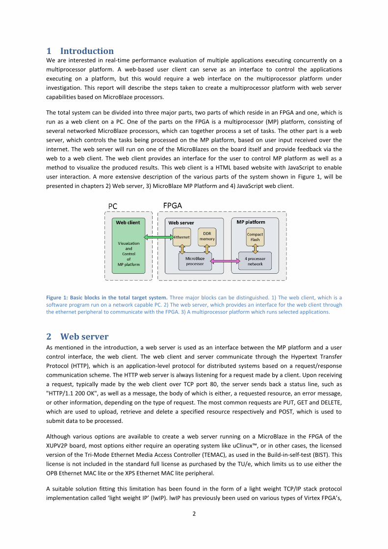
The total system can be divided into three major parts, two parts of which reside in an FPGA and one, which is
run as a web client on a PC. One of the parts on the FPGA is a multiprocessor (MP) platform, consisting of
several networked MicroBlaze processors, which can together process a set of tasks. The other part is a web
server, which controls the tasks being processed on the MP platform, based on user input received over the
internet. The web server will run on one of the MicroBlazes on the board itself and provide feedback via the
web to a web client. The web client provides an interface for the user to control MP platform as well as a
method to visualize the produced results. This web client is a HTML based website with JavaScript to enable
user interaction. A more extensive description of the various parts of the system shown in Figure 1, will be
presented in chapters 2) Web server, 3) MicroBlaze MP Platform and 4) JavaScript web client.
Figure 1: Basic blocks in the total target system. Three major blocks can be distinguished. 1) The web client, which is a software program run on a network capable PC. 2) The web server, which provides an interface for the web client through the ethernet peripheral to communicate with the FPGA. 3) A multiprocessor platform which runs selected applications.
2 Web server As mentioned in the introduction, a web server is used as an interface between the MP platform and a user
control interface, the web client. The web client and server communicate through the Hypertext Transfer
Protocol (HTTP), which is an application-level protocol for distributed systems based on a request/response
communication scheme. The HTTP web server is always listening for a request made by a client. Upon receiving
a request, typically made by the web client over TCP port 80, the server sends back a status line, such as
"HTTP/1.1 200 OK", as well as a message, the body of which is either, a requested resource, an error message,
or other information, depending on the type of request. The most common requests are PUT, GET and DELETE,
which are used to upload, retrieve and delete a specified resource respectively and POST, which is used to
submit data to be processed.
Although various options are available to create a web server running on a MicroBlaze in the FPGA of the
XUPV2P board, most options either require an operating system like uClinux™, or in other cases, the licensed
version of the Tri-Mode Ethernet Media Access Controller (TEMAC), as used in the Build-in-self-test (BIST). This
license is not included in the standard full license as purchased by the TU/e, which limits us to use either the
OPB Ethernet MAC lite or the XPS Ethernet MAC lite peripheral.
A suitable solution fitting this limitation has been found in the form of a light weight TCP/IP stack protocol
implementation called ‘light weight IP’ (lwIP). lwIP has previously been used on various types of Virtex FPGA’s,
3
but as of yet, not on the XUPV2P. The basic hardware for the web server was created using the Base System
Builder (BSB) wizard in the Xilinx Platform Studio (XPS), based on the hardware description in [1]. The used c-
code is borrowed from a Spartan3 example included in the lwIP download and hence has to be slightly adjusted
to work on the XUPV2P board. Appendix A.1 gives a step by step description of the whole process of creating
and running of the web server. The main peripherals used by the web server are the Ethernet interface and the
DDR, in which both the website as well as the software application for the MicroBlaze are stored. Creating a
system including DDR caused a lot of trouble until Xilinx EDK 10.1 SP3 was installed, which is the only EDK
version which fully supports the DDR peripheral. The resulting, working web server can now serve as a base for
the development of the rest of the project.
Although the web server is working correctly now, processing either POST or GET request from the HTML-
clients is still very slow, with a throughput of only 10-30kB per second. In the target application, which is not
very big, this in itself would not pose a problem but for the long latency the web server also introduces. POST
requests could take up to 5 seconds to process and respond, which is unacceptable in a system where an
update is requested every few seconds. Changing the size of the send buffers hardly had any effect, but adding
caching of the DDR for both the instruction and data memory, in the on chip BRAM memory blocks, reduced
the response time of the web server to fractions of a second.
As mentioned before, the web server is able to process both POST and GET requests. This is done in a very
straight forward manner in which a string compare of both “POST” and “GET” is performed on any incoming
request. Depending on the type of request that has been sent, either a 404-error is returned or one of the
functions do_http_post() or do_http_get() is executed. In case of a GET request, the first 4 characters of the
received string are skipped and the rest is interpreted as a filename in the MFS. The corresponding file, if
available, will be returned. In case of a POST request the first part of the received string after skipping 5
characters, is compared to various known commands. The rest of the string, after the part that resulted in a
positive comparison is treated as input data. The specific POST requests used by both the web client and server
are treated in the chapter 4.2.
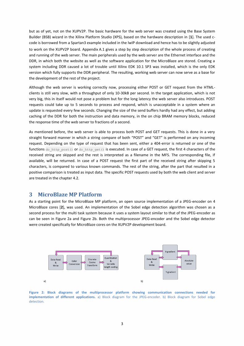
3 MicroBlaze MP Platform As a starting point for the MicroBlaze MP platform, an open source implementation of a JPEG-encoder on 4
MicroBlaze cores [2], was used. An implementation of the Sobel edge detection algorithm was chosen as a
second process for the multi task system because it uses a system layout similar to that of the JPEG-encoder as
can be seen in Figure 2a and Figure 2b. Both the multiprocessor JPEG-encoder and the Sobel edge detector
were created specifically for MicroBlaze cores on the XUPV2P development board.
Figure 2: Block diagrams of the multiprocessor platform showing communication connections needed for implementation of different applications. a) Block diagram for the JPEG-encoder. b) Block diagram for Sobel edge detection.

4
To combine the two projects only one extra Fast Simplex Link (FSL) is needed in the system design made for the
Sobel edge detector. Two additional FSLs were added between the web server and the MP platform, to enable
communication between these two parts of the system. The structure of the system containing both a web
server and a MicroBlaze MP platform that accommodates both the JPEG-encoder and the Sobel edge detection
algorithm is shown in Figure 3.
Figure 3: Block diagram showing all MicroBlaze processors and FSLs needed to support both JPEG and Sobel applications.
Because the MicroBlaze MP platform was designed in an older version of Xilinx however, the hardware still
used an On-Chip Peripheral Bus (OPB), which poses a problem when working in Xilinx EDK 10.1, where the
newer and faster Processor Local Bus (PLB) is used instead. The problem arises because no OPB to PLB bridge is
available to connect the PLB, generated for the web server, and the OPB, used by the MP platform. This means
that either the web server or the MP platform has to be redesigned to use another bus. For the new combined
design, the new and faster PLB bus was chosen over the outdated OPB bus, which meant that the structure of
the MP platform had to be rebuilt to fit the web server.
Since the system is now able to run two different tasks, the web server will have to have a notion of what a
task is, in order to control which task to run. The choice of which task to run, is made based on the information
received from the user through the web client, and on the time previously spent on each task. This
combination determines the priority of all possible tasks and of which task to run next. The basic structure of
the used code is shown in the flowchart diagram of Figure 4.
Figure 4: Flowchart diagram of the task control system in the web server. After starting the control flow keeps making clockwise circles through the flowchart, unless the MP platform is stopped by the user, or while the MP platform is already executing a task.
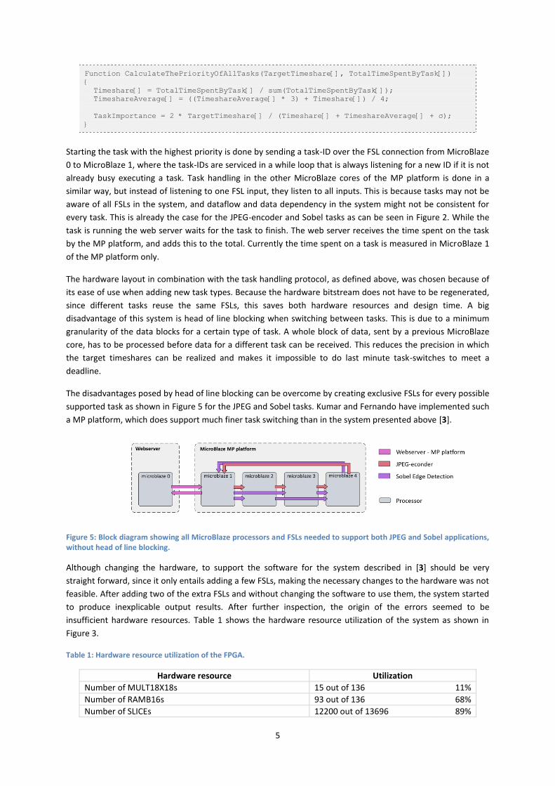
After the web server has started, no task will be issued until the web client sends a request to start the MP
platform. Based on the target timeshares received from the web client and the total time spent by each task,
the priorities of all tasks are calculated using the function CalculateThePriorityOfAllTasks(), as shown in
the following code fragment:
5
Function CalculateThePriorityOfAllTasks(TargetTimeshare[], TotalTimeSpentByTask[])
{
Timeshare[] = TotalTimeSpentByTask[] / sum(TotalTimeSpentByTask[]);
TimeshareAverage[] = ((TimeshareAverage[] * 3) + Timeshare[]) / 4;
TaskImportance = 2 * TargetTimeshare[] / (Timeshare[] + TimeshareAverage[] + σ);
}
Starting the task with the highest priority is done by sending a task-ID over the FSL connection from MicroBlaze
0 to MicroBlaze 1, where the task-IDs are serviced in a while loop that is always listening for a new ID if it is not
already busy executing a task. Task handling in the other MicroBlaze cores of the MP platform is done in a
similar way, but instead of listening to one FSL input, they listen to all inputs. This is because tasks may not be
aware of all FSLs in the system, and dataflow and data dependency in the system might not be consistent for
every task. This is already the case for the JPEG-encoder and Sobel tasks as can be seen in Figure 2. While the
task is running the web server waits for the task to finish. The web server receives the time spent on the task
by the MP platform, and adds this to the total. Currently the time spent on a task is measured in MicroBlaze 1
of the MP platform only.
The hardware layout in combination with the task handling protocol, as defined above, was chosen because of
its ease of use when adding new task types. Because the hardware bitstream does not have to be regenerated,
since different tasks reuse the same FSLs, this saves both hardware resources and design time. A big
disadvantage of this system is head of line blocking when switching between tasks. This is due to a minimum
granularity of the data blocks for a certain type of task. A whole block of data, sent by a previous MicroBlaze
core, has to be processed before data for a different task can be received. This reduces the precision in which
the target timeshares can be realized and makes it impossible to do last minute task-switches to meet a
deadline.
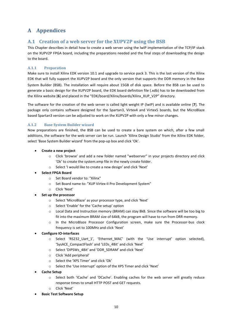
The disadvantages posed by head of line blocking can be overcome by creating exclusive FSLs for every possible
supported task as shown in Figure 5 for the JPEG and Sobel tasks. Kumar and Fernando have implemented such
a MP platform, which does support much finer task switching than in the system presented above [3].
Figure 5: Block diagram showing all MicroBlaze processors and FSLs needed to support both JPEG and Sobel applications, without head of line blocking.
Although changing the hardware, to support the software for the system described in [3] should be very
straight forward, since it only entails adding a few FSLs, making the necessary changes to the hardware was not
feasible. After adding two of the extra FSLs and without changing the software to use them, the system started
to produce inexplicable output results. After further inspection, the origin of the errors seemed to be
insufficient hardware resources. Table 1 shows the hardware resource utilization of the system as shown in
Figure 3.
Table 1: Hardware resource utilization of the FPGA.
Hardware resource Utilization
Number of MULT18X18s 15 out of 136 11%
Number of RAMB16s 93 out of 136 68%
Number of SLICEs 12200 out of 13696 89%

6
Without the intended changes, the basic layout of the total system hence looks like the block diagram shown in
Figure 6. This already includes the web client, which is actually only a HTML and JavaScript webpage, as
described in chapter 4, run on a normal PC.
Figure 6: Block diagram of the total system showing all essential components and communication paths. Although three communication paths using the LMB are drawn to indicate the peripheral utilization by the MicroBlaze processors, in hardware this is only one bus.
When running the total system it becomes clear that the MP platform in the FPGA is not used to its full
potential, since only about 35% of all cycles counted by the web server are used by the MP platform to perform
calculations. The origin of this discrepancy is not clear, since counting not only all cycles spent on a task, but all
cycles in MicroBlaze 1, also produces a cycle count, which is much lower than that of MicroBlaze 0 in the web
server. The difference in cycle count might be related to control or communication overhead, pipelining and
task switching delays or delays introduced by read and write operations to the Compact Flash card on which
the data is stored. A possible solution to the problem of MP platform inefficiency, and the lack of hardware
resources mentioned previously, might be found in combining MicroBlaze 0 of the web server and the 1st
MicroBlaze core of the MP platform. This reduces both the hardware utilization and also decreases control
overhead and latency because of the reduced core-to-core communication. Because of the reduced hardware
utilization, the MP platform as proposed by Kumar and Fernando can be implemented, increasing task
switching capabilities.
4 JavaScript web client A JavaScript based web client is an easy way to simplify both, user interaction with the web server and MP
platform, and visualize the created results in real time. The basic structure of the web client, which is shown in
Figure 7 has been created using HTML, but all user interaction is based on JavaScript. This choice was made,
because JavaScript allows for asynchronous processes and client side computation, strongly reducing the load
on the server. The result is a website that has to be loaded just once at startup, and only has to communicate
short strings of information with the server for each update.

7
Figure 7: View of the client website.
4.1 User interaction The web client introduced in Figure 7 contains several elements for user interaction, both for control and visual
feedback. The most prominent feature of the web client is the graph, created in JavaScript using a canvas[4],
which visualizes the timeshare of each task since the last update. Additionally it displays the actual timeshare
of each task realized since the last change of the target timeshares, using the short colored lines at the right
side of the graph. Both the target- and actual timeshares of each task are also displayed in the legend. Above
the graph information is available about the total runtime in seconds, as well as the last action performed or
possible errors.
The control of the web server is divided into three parts: start/stop, target timeshares and visualization
options.
The Start/Stop-button is located in the top left corner and starts or stops the execution of tasks on the
MP platform, as well as the timed requests for new updates from the web server.
The target timeshares can be set by changing the percentages in the Target column of the legend and
pressing ‘Set timeshares’. When setting the timeshares, they do not have to add up to 100%, since the
web client automatically calculates and displays the target percentage, based on the given fractions.
The remaining controls ‘Update time’, ‘Time scale’ and ‘Switch display mode’ are mainly for
visualization purposes.
o ‘Update time’ sets the number of seconds, between each request for actual timeshare
realization from the server.
o ‘Time scale’ sets the resolution of the horizontal time axis.
(Changes to either control setting are implemented during the next graph update.)
o ‘Switch display mode’ switches between two different graph modes, one of which is shown in
Figure 7, where the timeshare of each task is calculated relative to the total time spent by all
tasks. The other mode, shown in Figure 8, displays the timeshares, relative to the total
number of cycles spent by MicroBlaze 1, since the last update in the web server. Because the
MP platform is not active all the time, as mentioned in chapter 3, an extra (grey) line is added
to indicate the timeshare the MP platform was active, compared to that of the web server.

8
Figure 8: View of the graph when displayed in the alternate display mode. (The top of the graph has been lowered by about 40%)
To simplify possible modifications to the JavaScript web client, it contains an automatic debug mode, which
activates when running from a local file system. In debug mode no client-server interaction is performed, which
would only result in a time-out, and the graph-buffer is filled with fake data to test the graph functionality.
4.2 Client-Server communication Once the website has loaded, the client-server communication takes place using POST requests. This means
that all data sent with a request, or received in response to a request, is formatted as a single string. The POST
requests are generally very simple commands without much data, and no special care has to be taken to
format the data contained in the strings. As a response to the Update-request however, a lot of information
has to be sent, which would mean a lot of string parsing. A solution to this problem is found in strings
formatted in the JavaScript Object Notation (JSON) [5]. A string, when formatted correctly, can be evaluated by
a built in function eval() and is converted into an array of objects automatically. An example of a correct JSON
string is displayed below.
[
{ "taskName":"Task 1", "count":20, "timeTaken":1347022, "timeSinceUpdate":4962845 },
{ "taskName":"Task 2", "count":6, "timeTaken":1325708, "timeSinceUpdate":4962845 },
{ "taskName":"Task 3", "count":13, "timeTaken":864310, "timeSinceUpdate":4962845 }
]
It is now possible for the user to interact with the web server and the MP platform using the interface provided
by the web page. Table 3 shows the communication transactions and the functions performed by the total
system after an input, in this case pushing the ‘Start’-button, by the user has been detected.
Table 2: Example of the interaction between the web client and web server resulting from a user input.
User o Push ‘Start’-button
Web client o Send “POST setvarsxhr/500;500;0;/”
Web server o Receive and parse command o Set the target timeshare o Send response “1”
Web client o Receive response and display “Target timeshares set successfully” o Send “POST updatexhr”
Web server o Receive and parse command o Calculate task priorities o The multiprocessor is not yet running: start the multiprocessor platform by
sending a task-ID based on priority o Send a JSON response string
Web client o Receive and evaluate JSON string o Display graph
9
5 Conclusion The presented system allows a user to control the tasks running on a MP platform, over a network connection
on any available networked PC. This is possible because of the use of a light weight TCP/IP stack protocol,
which allows the use of HTTP request/response communication between a web client, and the web server
running on a XUPV2P board. The combination of web server and MP platform allows for a controlled switching
between tasks on the MP platform. The data rate achieved by the web server for communication over the
internet however, is very low, which results in a slow loading website. Because of added caching of the DDR for
the web server application, the response time of the web server to incoming HTTP requests is still very short,
which allows for a fast control flow and a high update rate during a test.
The created JavaScript webpage interface allows for fast interaction with the web server and displays any
simulation results in a clear way. The communication protocol used between the web client and server, also
allows for simple addition of alternate functionality. In theory, functionality of the web server combined with
the design of the MP platform and the choice of protocol, allow the SoC to perform any number of tasks,
without redesigning the hardware. Head of line blocking of the FSLs however limits the switching capabilities of
the system and therefore also limits the number of concurrently running tasks.
All software and hardware definition files created for this project, are available online [9] and appendix A.3)
Available project files and information, gives a full overview of the available files and information.
5.1 Future work Although the combination of web server and MP platform allows for a controlled switching between tasks, the
initial choice of interconnect reduces its ability to switch in a fine grained manner, because of head of line
blocking in the FSLs. The presented 5 core solution however, did not allow for implementation of the
alternative MP platform presented by Shabbir and Fernando, because of hardware constraints as mentioned at
the end of chapter 3. Combining MicroBlaze 0 and MicroBlaze 1 in Figure 6, might resolve this problem, and
also reduce communication overhead. The feasibility of this solution however, depends on the resources
required from the MicroBlaze processor for running the web server. Apart from the head of line blocking,
switching to a 4 core solution using a more fine grain approach to the task switching might also increase the
utilization of the MP platform, which is currently very low, although the origin of this problem is not clear yet.
The speed of web server, especially the data transfer rate, is also a point of concern. Although the current
speed of the web server suffices for the current web application, for example for up- or downloading of images,
will be almost impossible, without additional functionality of the web server. Also, according to [1] the date
transfer rate of the server could be as high as 1MB per second instead of the current 30kB. Because adding
caches to the web server decreased access times significantly, communication with the DDR might be the
reason for its low performance.
An additional improvement to the system can be made by creating a boot loader, which loads the software
program for web server, as well as the data used by the MP platform, from the Compact Flash card to the DDR
memory. This simplifies the startup process significantly, which would also make it possible to do a remote
reset of the system, which is currently impossible. Potentially it might also speed up the processing of
applications in the MP platform because less reads and writes to the CF-card are performed.
10
A Appendices
A.1 Creation of a web server for the XUPV2P using the BSB This Chapter describes in detail how to create a web server using the lwIP implementation of the TCP/IP stack
on the XUPV2P FPGA board, including the preparations needed and the final steps of downloading the design
to the board.
A.1.1 Preparation
Make sure to install Xilinx EDK version 10.1 and upgrade to service pack 3. This is the last version of the Xilinx
EDK that will fully support the XUPV2P board and the only version that supports the DDR memory in the Base
System Builder (BSB). The installation will require about 15GB of disk space. Before the BSB can be used to
generate a basic design for the XUPV2P board, the EDK board definition file (.xdb) has to be downloaded from
the Xilinx website [6] and placed in the “EDK/board/Xilinx/boards/Xilinx_XUP_V2P” directory.
The software for the creation of the web server is called light weight IP (lwIP) and is available online [7]. The
package only contains software designed for the Spartan3, Virtex4 and Virtex5 boards, but the MicroBlaze
based Spartan3 version can be adjusted to work on the XUPV2P with only a few minor changes.
A.1.2 Base System Builder wizard
Now preparations are finished, the BSB can be used to create a bare system on which, after a few small
additions, the software for the web server can be run. Launch ‘Xilinx Design Studio’ from the Xilinx EDK folder,
select ‘Base System Builder wizard’ from the pop-up box and click ‘Ok’.
Create a new project
o Click ‘browse’ and add a new folder named "webserver" in your projects directory and click
‘Ok’ to create the system.xmp file in the newly create folder.
o Select ‘I would like to create a new design’ and click ‘Next’
Select FPGA Board
o Set Board vendor to: "Xilinx"
o Set Board name to: "XUP Virtex-II Pro Development System"
o Click ‘Next’
Set up the processor
o Select ‘MicroBlaze’ as your processor type, and click ‘Next’
o Select ‘Enable’ for the ‘Cache setup’ option
o Local Data and Instruction memory (BRAM) can stay 8kB. Since the software will be too big to
fit into the maximum BRAM size of 64kB, the program will have to run from DRR memory.
o In the MicroBlaze Processor Configuration screen, make sure the Processor-bus clock
frequency is set to 100MHz and click ‘Next’
Configure IO-interfaces
o Select ‘RS232_Uart_1’, ‘Ethernet_MAC’ (with the ‘Use interrupt’ option selected),
‘SysACE_CompactFlash’ and ‘LEDs_4Bit’ and click ‘Next’
o Select ‘DIPSWs_4Bit’ and ‘DDR_SDRAM’ and click ‘Next’
o Click ‘Add peripheral’
o Select the ‘XPS Timer’ and click ‘Ok’
o Select the ‘Use interrupt’ option of the XPS Timer and click ‘Next’
Cache Setup
o Select both ‘ICache’ and ‘DCache’. Enabling caches for the web server will greatly reduce
response times to small HTTP POST and GET requests.
o Click ‘Next’
Basic Test Software Setup
11
o You can deselect both sample applications if you wish, but activating one to test the
functionality of the system is advised to test the generated system.
System Created
o Click ‘Generate’, this only takes a second.
Finish
o Click ‘Finish’
A.1.3 Adjusting settings and software
A basic system containing one processor, various peripherals and the connecting busses now has been created.
Now various libraries have to be added and set correctly before a slightly altered version of the available lwIP
code can be used to finish the web server.
Go to ‘Software Software Platform settings’ in the top menu bar
In the ‘OS & Library settings’ part of the ‘Software Platform’ tab, use the 'xilmfs' and 'lwip' libraries
The 'xilmfs' settings in the "OS and Libraries" tab have to be changed to the following settings:
o ‘need_utils’ = ‘true’
o ‘init_type’ = ’MFSINIT_IMAGE’
o ‘base_address’ = ‘0x92000000’
o ‘numbytes’ = ‘8000000’
The ‘base_address’ should be within the address range of the DDR memory and far enough from
C_MPMC_BASEADDR defined in ‘System Assembly View Addresses’ to allow space for the program
code. ‘num_bytes’ should be big enough to fit the total memory file system; here it is set to 8MB.
The ‘lwip’ settings can remain unchanged.
In the ‘Project Information Area’, under the ‘Applications’ tab, click ok ‘Add Software Application
Project…’ to create a new software project
Right-click on the Sources folder of the new project to select "Add existing files" and select all files
necessary for the project from the RAW/Spartan3 folder of the lwIP project. The necessary files are:
o main.c
o webserver.c
o web_utils.c
o http_response.c
o platform.c
o platform_fs.c
o platform_gpio.c
o webserver.h
Right-click on the newly created project folder and select ‘Set Compiler options’. Under the ‘Paths and
Options’ tab, add "-llwip4" to the ‘Libraries to Link against (-l)’ text input field and click ‘Ok’
Once more right-click on the project folder, but now select ‘Generate Linker Script’.
Set all Memory pull-down boxes in 'Sections view' and ‘Heap and Stack View’ parts to
"DDR_SDRAM_C_M". In the ‘Heap and Stack View’, increase the size of both memories from 400 to
20000 Bytes and press 'Ok' to generate the special linker script for this MicroBlaze processor.
Select ‘Software Generate libraries and BSPs’ in the top menu bar
Now add the following 2 lines of code
#elif defined(XPAR_DIPSWS_4BIT_BASEADDR)
#define DIP_BASE XPAR_DIPSWS_4BIT_BASEADDR

12
to line 20 in the platform_gpio.c file, which correctly defines the dipswitches located on the board as
an input.
Set the IP-address, subnet mask and gateway address of the web server to correspond with your local
network settings. All three of these values can be set using the function IP4_ADDR() on lines in main.c.
The MAC-address of the board is not fixed in hardware but rather set in software. To change the MAC-
address to a use full on, set ‘mac_ethernet_address[]‘, in the main.c file, to the address of your
choice. The MAC-address can be any 6-char code, but to be sure that the address is unique Xilinx
advises to use the code, printed under the barcode on the XUPV2P board, as the MAC-address
Use ‘Generate Bit stream’ to build both the hardware and software part of the web server project.
This step can take up to 30-45 minutes.
A.1.4 Download and execute
Now that the web server project has been created and built it only has to be downloaded to the board and
tested. This next section will describe the steps involved.
Open HyperTerminal, or any other serial interface terminal emulator program, and start a connection
using the settings as shown in Table 3.
Table 3: Serial port interface settings
Baud-rate 9600
Data bits 8
Parity None
Stop bits 1
Flow control Hardware
This way, HyperTerminal can be used to receive (debug) information from the XUPV2P board. In case
of the web server application, information about the startup of the server as well as all received POST
and GET requests are sent to the serial RS232 port and displayed by HyperTerminal.
Click on the ‘Download Bitstream’ button in the top menu bar. This function is also available in the top
menu bar at ‘Device Configuration Download Bitstream’. This downloads the hardware
configuration to the FPGA and also initializes the BRAM memory blocks. Because both the program
memory and the Memory File System (MFS) containing the website reside in the DDR, additional steps
are necessary to load these to the board.
Go to ‘Debug XMD Debug Options’ in the top menu bar, select “USB" as ‘JTAG Cable Type’ and click
‘Ok’
Run ‘Debug Launch XMD’ from the top menu bar to open a command line dialog from which we
can communicate with the FPGA.
In the command line tool, type "dow webserver/executable.elf" to download the generated bitfile
to the DDR memory
Type "dow -data webserver/image.mfs 0x92000000" to download the image.mfs file containing the
website and files to location 0x92000000 in the DDR memory. 0x92000000 could be different for every
board/installation depending on the memory address the DDR has been given, and this should be the
same as the memory address selected in appendix A.1.3. An image.mfs file is supplied with the lwIP
download, but it is also possible to create a new MFS. This process is described in Creation of a
Memory File System.
Type "run" to start the FPGA
In your favorite browser, surf to the IP-address selected in appendix A.1.3.
Type "stop" to stop the FPGA (More commands are available and described on page 160 of [8])

13
A.2 Creation of a Memory File System To host a personal website on the web server running on the XUPV2P board, a MFS has to be created, which
can be loaded into the DDR memory as described in the final part of Creation of a web server for the XUPV2P
using the BSB.
Launch the Cygwin command line tool available with the Xilinx software package. In windows, this
shell is accessible from the start menu through ‘Xilinx ISE Design Suite 10.1 EDK Accessories
Launch EDK Shell’.
Go to the directory containing all the files and folders used for the website and use the mfsgen
command to create a MFS. This should look something like:
mfsgen –cvbfs ../image.mfs 300 index.html css js
The previous example would result in a new image.mfs file in the directory one up from the current
directory of size 300*532 = 159600bytes, containing the file ‘index.html’ and the folders ‘css’ and ‘js’
including all files in these directories.
A.3 Available project files and information All the source code for both the software and the hardware described in this report is available online. The files
as well as the report itself are available online at [9] as part of the MAMPS website [10].
Web server: Hardware description files for the web server based SoC including the four processors MP
platform as described in this report as well as the software applications of the web server, JPEG-
encoder and Sobel edge detection.
Web client: Source files of the JavaScript web client as described in this report as well as a .mfs
Memory File System, ready for download onto the DDR of the FPGA.
Report: This report is available, both in a .PDF as well as a .HTML version.

14
B Bibliography [1] Xilinx. (2008, April) LightWeight IP (lwIP) Application Examples. [Online].
http://www.xilinx.com/support/documentation/application_notes/xapp1026.pdf
[2] MP-FPGA. (2007) Soft Multi Processor on FPGA. [Online]. http://mp-fpga.blogspot.com
[3] Akash Kumar, Shakith Fernando, Yajun Ha, Bart Mesman, and Henk Corporaal, "Multi-Processor System-
Level Synthesis for Multiple Applications on Platform FPGA," in Proceedings of Field Programmable Logic,
Amsterdam, 2007, pp. 92-97.
[4] Mozilla. (2009, April) Mozilla Development Center. [Online].
https://developer.mozilla.org/en/drawing_graphics_with_canvas
[5] JSON. JavaScript Object Notation. [Online]. http://www.json.org
[6] Xilinx. Xilinx University Program website for the Virtex 2 Pro. [Online].
http://www.xilinx.com/univ/xupv2p.html
[7] Adam Dunkels. (2001-2004) lwIP - A Lightweight TCP/IP stack implementation. [Online].
http://savannah.nongnu.org/projects/lwip
[8] Xilinx. (2008) Embedded System Tools Reference Manual - EDK 10.1, Service Pack 3. [Online].
http://www.xilinx.com/support/documentation/sw_manuals/edk10_est_rm.pdf
[9] Michiel Rooijakkers. (2009) MAMPS - Web server controlled multi-tasking on a FPGA based multiprocessor
platform. [Online]. http://www.es.ele.tue.nl/mamps/web_server
[10] Akash Kumar. MAMPS: Multi-Application Multi-Processor Synthesis. [Online].
http://www.es.ele.tue.nl/mamps