Embed Size (px)
Citation preview

The W8TEE BITX40 Modificationsby
Jack Purdum, W8TEE
Parts of this manual originally were written for members of my club, the Milford Amateur Radio Club, many of whom had never built a kit before. I kitted the parts for the PKAA Antenna Analyzer, something I will NEVER do again! My appreciation goes out to everyone who creates a bag of parts for a kit. Because of that background, some of the instructions apply to parts of that kit, but you are required to buy your own parts. Once acquired, you can use this manual to build the modifications for the BITX40 (B40 from now on).
The W8TEE B40 has the following enhanced features:
Color TFT display to replace the 2x16 Raduino display that comes with the B40 Auto-sizing for different mcufriend TFT displays (2.4”, 2.8”, 3.5”, and 3.95”) Arduino Mega 2560 Pro Mini microcontroller to replace the Raduino's Nano microcontroller. CW mode Electronic keyer Up to 50 stored CW messages, selectable at runtime AGC with S meter driven off the RF chain Speech compressor Voltage monitor High quality PCB that simplifies connections to the Arduino Mega2560 Pro Mini board and the
TFT display plus easy access to the Mega's I/O pins for experimenting
The purpose of this manual is to help you build the TFT/VFO display. We also present some pre-construction ideas that may help you get organized for the assembly and make the construction easier.
Step 1. What you need to complete the B40 ModificationsTo complete the B40, you will need to purchase the parts that are given in the list of materials found at the end of this manual. In addition, you will also need:
1. A soldering station or iron. Usually a 25-30 watt iron is sufficient, but a soldering station is nice to have. It has a holder for the hot iron, a sponge for cleaning the tip while you solder, and an adjustable temperature control. (Most of the time I run at the hottest temp.) Figure 1 shows the station I use which is available on eBay (#271878518662) for about $25.

Figure 1. Solder station
2. Tools. Something to strip wires, needle nosed pliers, small screw drivers (flat head and Phillips). If you use a box cutter to trim insulation from wires, try not to nick the wire in the process. For clipping component leads, I previously used toenail clippers. I have graduated to Xelite snips, as seen in Figure 2. They cost a little more, but I really like these snips.
Figure 2. Xcelite snips.
Warning: clipped leads know how to travel at the speed of light when clipped. Wearing protective glasses is a good idea.
3. Solder. Use rosin core solder only and the thinner, the better. I use .022” silver solder (62/36/2) which is a blend of tin, lead, and silver. I bought mine at Radio Shack, but it's getting hard to

find. (See bottom-left of Figure 4.) Check eBay. Unless you want to buy a pound of the stuff, it's useful to sort the eBay list by price.
4. Magnifying glass. (Also shown in Figure 4.) Even with good eyesight, it makes reading resistor band colors and capacitor numbers easier. Good lighting is important when reading color bands. Purple and blue look a lot alike in poor lighting.
5. A digital multimeter (DMM). Don't chintz here...get a good one. I really like mine, an AideTek VC97. (See Figure 3, eBay #290513474085). You can buy this one on eBay for less than $30. It can be used to check resistance, voltage, amperage, capacitance, and transistors and comes with a nice case for storage. It even has a temperature sensor. Also, if you leave it unattended for a few minutes, it beeps to remind you to turn it off.
Figure 3. The Aidetek VC97 multimeter.
What follows is a list of things that are nice to have, but not required
1) Solder sucker (#351065197104) or solder wick (#290768709802). Used to remove solder from a connection if a solder error is made (e.g., soldering the wrong resistor in place). If you never make a mistake, you don't need it.

2) PCB holder, about $10.00 (#401112964765). Makes it easier to hold a PCB in place while mounting and soldering components. I bought one on eBay because I build a lot of kits. See Figure 4. You can rotate the board easily after mounting the parts for soldering the components on the “under” side of the board. You can also see a dirty old towel under the holder as sometimes I drop a part and it's easier to find on the towel, plus the parts don't bounce when they hit the table. You'd be surprised how hard it is to see an 1/8W resistor on certain types of carpet. (I'm old and it happens.)
Figure 4. PCB holder.
Step 2. Getting ReadyWhen you do a parts inventory, it's worthwhile sorting the parts so they are easy to locate. I often use a sheet of packing styrofoam to stick the components in, even though it's not a good idea for static-sensitive parts. (Figure 5 shows the parts for the Forty-9er transceiver kit prior to assembly.) Note how

Figure 5. The Forty-9er kit before assembly.
some capacitors are “in a line”. That means they are all the same value. I also do this for resistors.
Another good “parts holder” is an old egg carton. I've also seen builders take a 4” strip of cardboard, bend it into a 'U' shape, and place components in the corrugation channels. Whatever method you use, the point it to make it easy to identify and reach the parts.
As you place a component onto the PCB (or otherwise add to the project), make sure you check it off your parts list once it's in place. Obviously, you want your “parts holder” to be empty when all of the items on your parts list are checked off.
Figure 6 shows several of the parts in the project so you can tell them apart. (The figure shows 1N34
Figure 6. Some parts from the B40
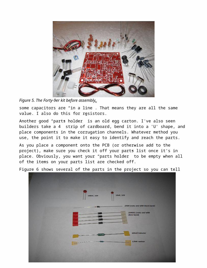
and 1N4001 diodes because the photo was taken from the antenna analyzer project. The B40 project only uses the 1N4001 diodes.) The diodes must be placed on the PCB so the silk screen band on the PCB matches the band on the diode. (The band on the PCB looks like a single line, but it actually forms a band with the end outline of the diode on the PCB.)
Figure 7 is a picture of the (unpopulated) Printed Circuit Board, PCB, that is used with the B40. The figure calls out several of the connection points on the PCB. Note there are several test points (e.g., TP1, TP2, etc.) on the left side of the board for taking voltage measurements along with a GND pin. The test points values are indicated on the schematic diagram. Note also that the holes underneath the “Encoder Switch Input” label and in line with the “Test Points” label are for the socket headers that will hold the TFT display which mounts on the “backside” of the PCB.
Figure 7. PCB with several connections to external components shown.
Before we start adding components, you should read through all of this manual at least twice. That will give you a good idea of how things will go together. Also, it is easier to drill the holes in the case that will later secure the PCB and display if that drilling is done before any components are on the board. That way, you can lay the PCB flat on the bottom of the case for marking the mounting holes.
Okay, it's time to start building.
Buying PartsDepending upon where you buy your parts, it is often cheaper to buy a resistor assortment than buy them one at a time. One local parts store sells resistors at $1.50 for two resistors. I buy a resistor assortment from a GA eBay store (#192184944181) with an assortment of 130 values @ 20 each for $10. I buy my capacitors the same way (#321891053652), 1000 @ 50 different values for $7. These stores bag/label the parts, a service which some vendors do not do. It's worth having the parts labeled. Some of the resistors are “taped” together, as they were cut from a reel of like values. All of the

resistors are 1/8W, so you don't need to worry about that characteristic. However, you do need to make sure that you select each resistor with the correct resistance before placing it on the PCB.
The resistor and capacitor values used in this project are not that critical. Being off 10% for the resistors or capacitors shouldn't make any difference. If you build more critical circuits (e.g., a tune circuit), you may need more precise values.
Step 3. Adding the resistorsSeveral recommendations:
1. Follow the sequence for mounting components as suggested below. Sometimes placing one part is more difficult if you have already mounted some other part first. The sequence is done to minimize such issues.
2. Don't mount all resistors at one time. Do them in small groups of no more than 6 or 7 at a time.
3. I prefer to mount all of the resistors with the same value at one time. For this project, I mounted the resistors in the same sequence shown in Table 1.
4. If you have a resistor assortment, each group is part of a “tape” which holds a label for that resistor's value. Clip the resistor leads near the tape holding them together, thus preserving the label for later use.
5. Measure each resistor before placing it on the board. Do the same for capacitors.
6. Reread number 5.
7. Consistently mount all resistors so the color bands can be read left-to-right. Bend the leads in a 'U' shape before placing on the board, and then fan the leads on the back side of the board so it won't fall out.
Table 1. PCB resistorsTable 1. PCB resistorsOhms Color Code Schematic Part Number
82 Grey Red Black R1
1K Brown Black Red R3, R5, R7
2K* Red Black Red R2, R4, R6*A 2K resistor is an unusual value, but you can use a 2.2K as well.
Figure 8 shows all of the resistors in place, but they have not been soldered in place yet. When you solder them, place the soldering iron tip on the back side of the PCB and touch the soldering iron tip at the junction of the resistor lead and the pad where the lead comes through the PCB. A few seconds should be long enough to heat the joint. Now touch the solder to the nexus of the tip, the pad, and the resistor lead. The solder should quickly melt around the joint. Leave the tip on the joint for a second so the solder is drawn into the hole that holds the resistor. This will insure a good connection.
Before I clip any component leads, I “strum” each lead with my thumbnail. If the lead gives an almost a musical note, it's probably a good connection. If it gives a “thunk” sound when strummed, it's probably a cold solder joint and not a good connection. Re-heat the connection for a second or two and test again. Cold solder joints are probably the most common reason for the failure of a project.

Figure 8. Resistors in place.
Figure 9 shows the underside of the PCB where the resistors have been soldered in place and trimmed. Use whatever tool you have chosen to clip the resistor leads as close to the board as possible. In the figure, you can barely see where they are soldered to the board. Make sure you clip them as short as possible, as leads that are even a little bit long could bend directly above another solder-through hole. This could produce a short if you don't see it. Also, as the solder melts, it leaves a slightly sticky residue on the board. That's not a problem, but sometimes small pieces of clipped leads stick to the residue and could cause a short. Examine the board closely before you apply power to make sure you removed all of the excess lead clippings.
Figure 9. Resistor leads after testing, soldering, and clipping.
Proceed with soldering the remaining resistors in place and clipping their leads.

CapacitorsWhile there are over a dozen capacitors to mount, all but one are the same value so just do them as two separate steps. I always measure each component before placing it on the board. It's not uncommon to see the value vary by as much as 20%. Usually that's not a problem. In tuned circuits, you may want components with much less “slop” in their values. Each capacitor has a standard capacitor number stamped on it. I try to place the capacitor on the board so I can read these ID numbers easily. Elecraft has a great little table of the standard cap numbers:
http://www.elecraft.com/Apps/caps.htm
Sometimes neighboring components make it difficult to read their values, so a little thought about the numbers when putting them on the board can help.
Table 2. Capacitors and their standard numeric valuesValue Standard Number Schematic Part Number100nF 104 C1, C2, C3, C4, C5, C6, C7, C8, C9,
C10, C11, C12, C13
100uF, 25V C14Note: Inductors L2 and L3 on the PCB are mounted very close to the buck converter. I would suggest adjusting and mounting the buck converter before installing the two inductors or the row of adjacent capacitors. (See below.) This allows the inductors to “lean towards” the row of capacitors and making it easier to install the buck converter.
DiodesThere is only one diode type in this project: the 1N4001 diodes.
Diodes, transistors, and most semiconductor devices get a little cranky when you apply too much heat to them. Because of this, I have a sequence I use when soldering them to a board. First, I try to mount them so I can read their numbers. (For this board where the diodes are the same, it probably doesn't matter much.) I bend their leads in the same manner I do for resistors. However, when it comes time to solder them, I only solder one lead of a diode at a time. I move to the next diode and solder it, leaving one lead unsoldered on the first diode. I do this for all of the diodes on the board. When I'm done with this process, all of the diodes will have one lead soldered in place.
Now I go back to the first diode and solder the remaining lead in place, then move to the next one. Using this approach gives the diode some time to cool off before the second lead is soldered. When I'm done, I again strum each lead just to make sure there's no cold solder joint (or I didn't forget to solder a lead). I've told other builders about this process and they assure me it isn't necessary as long as you don't dawdle while the soldering tip is on the component. After hearing this, I ask them: “Have you ever had a diode fail from over-heating?” Most have. I've never had one fail. Quod erat demonstrandum. (Latin for: “Put that in your pipe and smoke it!”)

Table 3. Diodes used on the PCB.Diode type Schematic Part Number
1N34 D1, D2
1N4001 D3, D4, D5, D6
If you look closely at Figure 8 near the center of the board, you will see a small solid line towards the bottom of D1 and D2. These markings show the orientation of the diode. The “band end” of the diode marks the cathode and the unbanded end is the anode. This is shown in Figure 10.
You want to make sure the band painted on the diode aligns with the band silk screened on the PCB. The 1N4001 cathodes are clearly marked with a silver band. You can check this with your DMM by placing the scale on Resistance and the positive probe on the cathode and the negative probe on the anode. You will see a very high resistance...usually in the megohm range. Now reverse the leads and you will likely read zero resistance.
Figure 10. Diode markings.
The 1N4001 diodes all face the same way, with their cathodes closest to the bottom edge of the board in Figure 8. Solder them in place using the “alternating lead” technique.
Miscellaneous PartsThere are a number of other parts mounted to the PCB. We consider those in this section.
Adjusting/mounting the Buck ConverterThe B40 uses a buck converter to change the 12V from the power source to 7.6V. Ashhar has designed the B40 so a different voltage can be used to drive the final power amplifier (IRF510). We are not concern with the PA power source or its voltage. The buck converter is used to power the devices that are on our PCB only, including the Mega 2560 Pro Mini, the AD9850 module, and the TFT display. We used the buck converter rather than the usual 780X regulator because the converter is almost 75% more efficient than the older style regulators, plus it's adjustable. The voltage is adjusted with the small Phillips head screw that can be seen in Figure 11.
CAUTION: The Phillips head screw on the buck converter shown in Figure 11 is very fragile and can snap off easily. I recommend a jeweler's screw driver. Most of the home improvement stores sell these if you don't already have a set. (Harbor Freight sells a set with fairly large handles which I find easier to use than a jeweler's set.) Just remember not to force the screw...gently does it.

If you have a breadboard, you can use old resistor leads for the four pins used for the input and output of the converter. (Actually, I prefer to use left-over I/O header pins. If you do use I/O pins, remove the plastic collar after soldering them in place so it can fit closely to the PCB. The converter needs to be low enough to fit under the Mega 2560 Pro Mini.) For resistor leads, clip them to about a 0.5” length and insert them in your breadboard so they line up with the holes on the four corners of the buck converter. Slide the converter over the leads and solder into place and trim the leads on the top. The bottom leads will eventually be used to mount the converter on the PCB.
Now hook up a 12V source to the input pins, paying attention to the polarity. Attach the DMM leads to the converter's output terminals. Now gently turn the Phillips head screw until you see 7.6V on the meter. Try to get as close to 7.6V as possible, although it is not easy to get exactly 7.6V because the adjustment is fairly sensitive. A voltage between 7.3V and 7.9V should be fine.
Figure 11. The buck converter.

InductorsAs shown in Figure 6, the axial inductor looks a little bit like a resistor because it, too, has bands on it. However, compared to an 1/8W resistor, the inductor looks like it's on steroids so it's pretty easy to tell them apart.
Two of the 100uH inductors (L2, L3) are mounted towards the edge of the board, to the right of the buck converter. L1 is seated on the other side of the board, under the DDS module. Solder all three in place.
Header Pins and SocketsThe PCB brings out the Mega 2560 Pro Mini I/O pins so you can more easily add other components to the system. The Mega has memory resources such that we are barely using a 25% of its flash and SRAM memory. As a result, there is a forest of pins to attach to the board. Because some of the pins can make it a little harder to solder other components in place, you should start by soldering the TFT sockets on the back of the PCB, as shown in Figure 12.
Figure 12. Two 8-pin and two 6-pin sockets for TFT display on back of PCB.
Place the sockets in the appropriate holes and use a piece of tape to hold them in place while you solder them. I find that if you put a small blob of solder on an end pin and then apply a little pressure on the tape and then remove the tip of the iron, the socket seats snugly to the PCB. Do that on each of the end pins, one at a time. You want a “square fit” as you will likely mount the TFT in such a way that an uneven set of sockets will lead to an uneven mount of the TFT display. Once the four TFT pin sockets are in place, you can finish mounting the I/O pins on the front side of the PCB. This is shown in Figure 13.

Figure 13. The front side of the PCB will all components in place.
You should mount the 78L08 (U1) voltage regulator and the MAR-3SM+ (U2) first. These are on the left side of Figure 13. The voltage regulator needs to “lie down” so it can fit under the AD9850 module, so leave enough lead length so it can be bent down into place. The small dot near the top-left of U2 in Figure 13 aligns with the “triangle-cut” lead of U2.
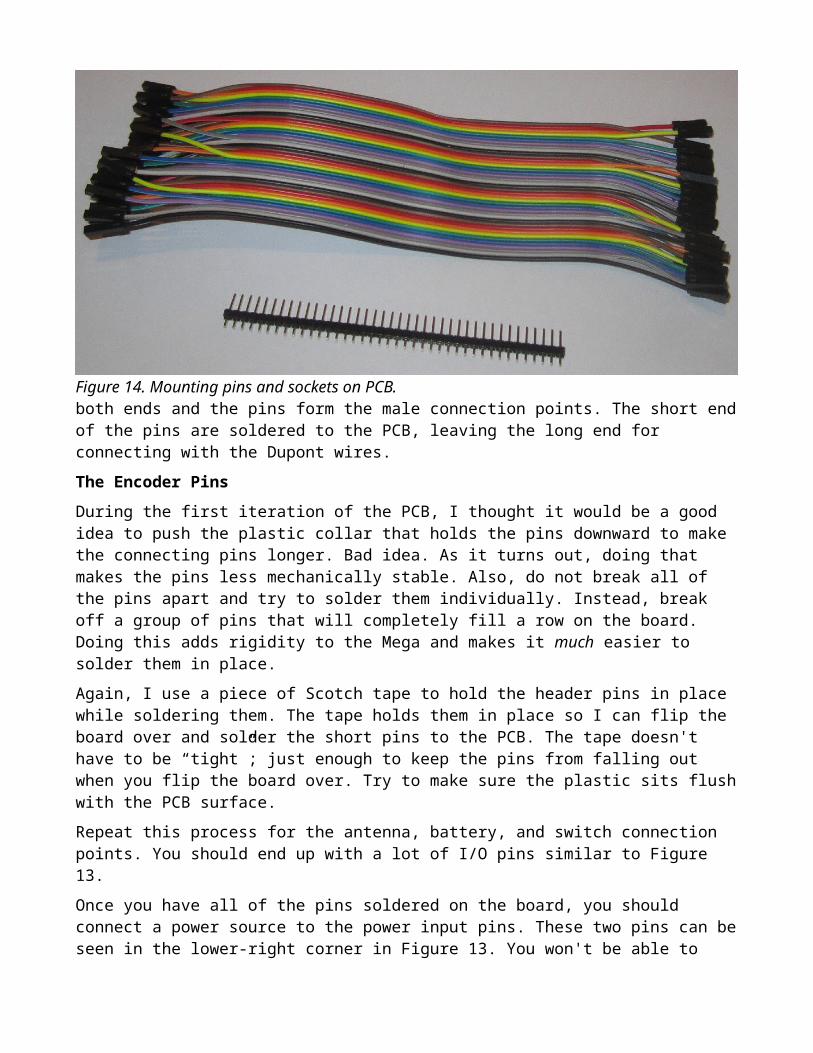
Header pins are used in conjunction with Dupont prototyping wires so that removing the boards is more easily done. These items are shown in Figure 14. Each of the wires has a plastic female connector on
Figure 14. Mounting pins and sockets on PCB.

both ends and the pins form the male connection points. The short end of the pins are soldered to the PCB, leaving the long end for connecting with the Dupont wires.
The Encoder Pins
During the first iteration of the PCB, I thought it would be a good idea to push the plastic collar that holds the pins downward to make the connecting pins longer. Bad idea. As it turns out, doing that makes the pins less mechanically stable. Also, do not break all of the pins apart and try to solder them individually. Instead, break off a group of pins that will completely fill a row on the board. Doing this adds rigidity to the Mega and makes it much easier to solder them in place.
Again, I use a piece of Scotch tape to hold the header pins in place while soldering them. The tape holds them in place so I can flip the board over and solder the short pins to the PCB. The tape doesn't have to be “tight”; just enough to keep the pins from falling out when you flip the board over. Try to make sure the plastic sits flush with the PCB surface.
Repeat this process for the antenna, battery, and switch connection points. You should end up with a lot of I/O pins similar to Figure 13.
Once you have all of the pins soldered on the board, you should connect a power source to the power input pins. These two pins can be seen in the lower-right corner in Figure 13. You won't be able to read all of the test point voltages without the Mega being in place. However, you should see about 12V at TP3, and 7.6V at the junction of L2 and C10. TP2 should show about 8V coming from the voltage regulator, U1. If these voltages appear correct, disconnect the power and plug in the Mega Pro Mini into its pins on the PCB.
Complete instructions for downloading and installing the Arduino IDE are given in Appendix A at the end of this manual. Load the Arduino IDE and the TFT/VFO sketch, select the Mega 2560 board from the Tools → Boards menu and set the Tools → Port selection to the COM port you use for your USB connection to the Mega. Connect the USB connector from your PC to the Mega, which should cause the Mega's power LED to light up. If the onboard LED does not light up or the USB serial I/O LEDs to
Figure 15. The TFT test display.
not light up when transferring a program to the MEGA, check to make sure all of the pins have been

properly soldered to the PCB and you have the IDE installed correctly. If there are no hiccups along the way, your display should look similar to that shown in Figure 15. (The TFT display still has the protective film on the display surface, which is why the colors are less vivid than the actually are.)
AD9850 Header SocketsThe AD9850 chip is responsible for generating the frequency signals for testing the SWR. It is a 21 pin chip using three sets of 7 pin headers. If you don't have 7 pin headers, you can take 8-pin header sockets and trim off one of the end pins. The remaining 7 pins of the header will still fit on the PCB even though one socket hole will not be used. Hey...any port in a storm. Placing the modified headers in the position makes the 7 active leads on the PCB align with the 7 “good pins” on the header socket.
Figure 16. Two different AD9850 boards.
If you have three 7 pin headers, you can ignore this paragraph.
Rotary Encoder ConnectionsThe rotary encoder connections are simple. Take 5 of the female-to-female Dupont wire connectors and slide them onto the 5 pins you see on the KY040 encoder. See Figure 17. I also soldered two 0.1uF capacitors from the A and B pins of the encoder to the encoder's ground pin. I also tried a 10K pull-up resistor on the switch pin, but the Mega's onboard pull-up resistors are good enough to do the job. Definitely leave the 10K resistor off the encoder. In fact, you might try the encoder without the capacitors to see if they are needed.
The purpose of the two capacitors is to “debounce” the encoder. Encoders work by sending out a pulse chain as you rotate the encoder shaft. By reading these pulses, the Mega can figure out if you are turning the shaft clockwise (CW) or counter-clockwise (CCW). Every 18 degrees, the encoder has a detent, or “speed bump”, which causes a contact to rise up and completes a circuit which creates the pulse chain. However, after hitting the detent, mechanical encoders like we are using tend to vibrate which can send out a false pulse chain. The Mega is fast enough to interpret the false pulse change as

encoder data. The capacitors remove the false pulse chain.
Figure 17. The KY040 rotary encoder.
Make the connections shown in Table 4 using the Dupont wires. You can use regular wire and solder it to the encoder pins, covering the joint with shrink tubing. That's what I did in figure 17. (The other end or the wires, however, did have the Dupont connectors, making it easy to remove the encoder if needed.) Table 4 shows the encoder connections and Figure 18 shows the section from Figure 13 where you will make the connections to the PCB. The Data connection from the encoder goes to the 5th pin
Table 4. Encoder Connections
Description of Pin From PCB Pin To Encoder PinGround connection G GND
Positive 5V connection + +
Switch S SW
Data connection B DT
Clock connection A CLK

Figure 18. The encoder connections on the PCB.
from the right of the top row (i.e., row 1) in Figure 18. This is also shown on the silk screen. The Clock connection connects immediately below the Data connection in row 2. The encoder Switch connection is to the immediate left of the Clock connection in row two. The GND and + connections from the encoder connect to the GND and 5V connections you see in the upper-right corner of Figure 18. That's all there is to it for the encoder wiring.
Boom! Done!
Appendix A
Download and Installing the Arduino Software
Arduino Software A c without software is about as useful as a bicycle without wheels. Like any other computer, a c needs program instructions for it to do something useful. Arduino has provided all the software tools within their (free) Integrated Development Environment (IDE) that you need to write program code. The remainder of this article discusses downloading, installing, and testing the software you need.
You need a place on your hard drive for the Arduino compiler and support files. I do not like to install it in the default directory (e.g., MyDownloads) because I find it difficult to navigate from the root directory to the Arduino directory. The most-current release of the Arduino IDE is 1.8.2, so I named my directory Arduino1.8.2 and placed it off the root of the C drive (e.g., C:\ Arduino1.8.2 ). This is where you will download and install the Arduino compiler and IDE. While you are at it, you might want to create a directory named C:\B40, too. You should use this directory to save this manual and the B40 source code sketch.
Start your Internet browser and go to:
http://arduino.cc/en/Main/Software
There you will find the Arduino software download choices for Windows, Mac OS X, and Linux. Click on the link that applies to your development environment. You are asked to select the directory where you wish to extract the files. Browse to your Arduino directory (C:\ Arduino1.8.2 ). Now download the file and run the installer.
When it finishes installing, look inside the Arduino directory you just created and double-click on the arduino.exe file. This should cause the IDE to start. After the IDE loads into memory, your screen should look similar to Figure A1. You should have your Arduino Mega2560 Pro Mini board connected to your PC via the appropriate (mini A) USB cable for your

Figure A1. The IDE startup screen.
board. All that remains is to select the proper Arduino board and port. Figure A2 shows how to set the IDE to recognize your board. As you can see, the one IDE supports a large number of the Arduino family. Click on the board that you are using.

Figure A2. Setting the Arduino board to use the Mega 2560 processor.
Now set the port number for the USB port that is being used to communicate between your Arduino and the PC. This is shown in Figure A3. Sometimes the Windows environment does not find the proper port. This is usually because the device driver for the port isn't found. If this happens, go to your installation directory and into the drivers subdirectory (e.g., C:\Arduino1.8.2\drivers) and run the driver installation program that's appropriate for your system. (Figure 5 shows the drivers subdirectory contents.)
Figure A3. Setting the communications port for the Arduino.
Figure A4. The drivers subdirectory
Once the driver is installed, the program should now find your Arduino COM port.

The Integrated Development Environment (IDE)The easiest way to test that everything installed correctly is to run a program. Your IDE has a program called Blink. You can find it using the menu sequence: File → Examples → 01. Basics → Blink. You can see this sequence in Figure A5. Once you click on Blink, the IDE loads it into the Source Code window.
Figure A5. Loading the Blink program.
Once the Blink program is loaded, the IDE looks similar to Figure A6. I've marked some of the more important elements of the IDE in the figure. Starting near the top is the Serial Monitor icon. You click on this to see any print statements you might be using in the program. We'll show an example of such statements in a moment.
The large white space is where you will write your program source code. Program source code consists of English-like instructions that tell the compiler what code to generate. Because you already loaded the Blink program, you can see the Blink source code in Figure A6.
The Compile Icon is exactly that: It compiles your program. It does not, however, link all the parts of the program together to form an executable program. Using the Compile Icon is a quick way to see if your have the code syntax correct.

Figure A6. The IDE.
The Compile-Upload icon not only compiles your program, but it links it into an executable program and then transfers the program code to the Arduino via the USB cable. In other words, your PC is used to write, test, compile, and debug your program, but the code actually runs on the Arduino. The Arduino has a small program, called a bootloader, that manages all of the communications between your PC and the Arduino. You don't need to worry about it. (If you compile a program on a Nano, it will tell you that you have about 30K of program space even though it's a 32K memory bank. The “missing” 2K is the bootloader. The picture was taken while using a Nano rather than a Mega 2560.)
The Program stats window tells you how much flash and SRAM memory your program is using. The window is also used to display error messages if the IDE detects something wrong with your program.
Actually, the compiler that sits underneath the Arduino IDE is the Gnu (Open Source) C++ compiler. That compiler can process C and C++ code, which is why so many of the libraries are written in C++. The Gnu compiler is very good at doing its thing. The Arduino IDE is a layer of abstraction that simplifies and insulates you from the complexity embodied in the C++ compiler and its use. As newer releases of the IDE appear, those developers are allowing more of the compiler complexity to shine through. As a result, library code that compiled without any error/warning messages under an earlier release of the IDE (e.g., 1.6.5) might issue a bunch of compiler warnings now because those developers are allowing more syntax and semantic compiler checks to filter through to the user. This is a good thing.

Compiler WarningsWhile improved compiler messaging is a good thing, it tends to obscure the goal of getting a program to work. The additional warnings may well leave you in a state of confusion since you have all of these ugly orange messages that now appear in the Stats window to contend with. Personally, I feel its the responsibility of the library developer to fix those errors, not me. The solution from your perspective: If the compiler completes the compile and uploads the binary to your Arduino board, you're good to go. While the warnings may indicate RDC (i.e., Really Dumb Code) library code, usually you can ignore them. Any fatal error in the code will halt the compile and prevent the upload. In that case, you need to fix whatever caused the error before you can proceed.
Your First Program Let's look at the Blink program and make a couple of simple changes to it. The code is reproduced in Listing 1, with all of the comments stripped away. Look at the element called setup(). The programming element named setup() is actually called a function.
Listing 1. Blink source code.void setup() { // initialize digital pin 13 as an output. pinMode(13, OUTPUT);}
// the loop function runs over and over again forevervoid loop() { digitalWrite(13, HIGH); // turn the LED on (HIGH is the voltage level) delay(1000); // wait for a second digitalWrite(13, LOW); // turn the LED off by making the voltage LOW delay(1000); // wait for a second}
A function is a group of one or more program statements designed to perform one specific task. The purpose of the setup() function is to define the environment in which the program is to operate. Without getting too deep right now, pinMode() is also a function which has been predefined for you to establish how a given Arduino I/O pin is to operate. In this case, we are saying that we want to use pin 13 to output data. However, every Arduino happens to have a small LED available for use on pin 13. In this program, therefore, we are going to use pin 13 to output data. As it turns out, the data to output consists of blinking the LED.
One thing that it unique about setup() is that it is only called once, and that is when you first apply power to the Arduino or you press its Reset button. Once it has defined its operating environment, its task is complete and it is not recalled.
The loop() function, however, is called continuously. If you look at the code, the first statement is a call to the digitalWrite() function. It has two function arguments, 13 and HIGH. Function arguments are pieces of information that must be sent to the function if that function is to perform its task properly.
Function CallsAny time you want to accomplish whatever task a function is designed to do, you “call” the function. The first line inside the loop() function, for example, calls (or invokes, or executes) the digitalWrite()

function code. When your program calls a function, program control is immediately transferred to the place in your program where that function's code appears.
I like to think of it this way: I'm hiking through the program code and I come to the call named digitalWrite(). Immediately, the program code grabs my backpack and jams the number 13 into it, followed by the word HIGH and returns my backpack to me. The next thing I know I'm standing in front of a black box with a door etched with digitalWrite() on it. A withered hand comes out from the black box door, grabs my backpack, retreats back into the black box, and slams the door shut. I don't know what's going on inside the black box. A few nanoseconds later, the door reopens and that same hand hands my backpack to me, and send me back to the next program instruction that follows the digitalWrite() function call. Program execute now resumes with the next program instruction, which happens to be a call to the function named delay().
Sometimes you'll see a function call like this:
compareOutcome = strcmp(“Jack”, “Jill”);
In this case, the code grabs my backpack, stuffs “Jack” and “Jill” into it and sends me and my backpack to the black box named strcmp(). The same gnarly hand grabs my backpack and disappears inside the black box. This function's task is to compare the two pieces of data (“Jack”, “Jill”) to see if they are the same (e.g., the function does a string compare). If the two strings are the same, the outcome is given the value 0 (zero). If the two are not the same, a non-zero value is the result. Now, here's the difference: The black box is going to stuff my backpack with a value of either 0 or non-zero before it hands it back to me and sends me back. When I do get back, the program code immediately opens my backpack, takes out whatever value is in there (non-zero in this example), and shoves that number into compareOutcome. Now, the program code can examine compareOutcome and make a decision based on that outcome.
Note: digitalWrite() stuffed nothing in my backpack, so its return value is void (i.e., nothing is returned from the function). Since the compiler knows that digitalWrite() returns nothing, it doesn't even bother checking my backpack when I return. On the other hand, the compiler does know that strcmp() does return a value in my backpack, so it will always execute code to look inside my backpack.
How does it know whether to look into the backpack or not? If you looked in the libraries for the two function and where the “black box” code is written you would see:
void digitalWrite(int whichPin, int whichValue){
// The digitalWrite () black box code...}int strcmp(char message1[], char message2[]){
// The strcmp() black box code}float min(float value1, float value2){
// The min() black box code}
The keyword word void at the start of a function definition is call the function type specifier and determines whether something is stuffed in the backpack or not. The keyword void means the function does not return anything in the backpack. The function type specifier for strcmp() is int, which means a two-byte integer value is stored in the backpack.

Finally, the min() function is designed to return the smaller of two values. In this case, because the values are floating point numbers, the function must return a floating point value. Note that, because a float requires 4 bytes of storage, when we return from the call to min(), the code knows to not only get the value stored in the backpack, it knows it must grab 4 bytes of data from the backpack. With strcmp(), it only grabs 2 bytes from the backpack, because that's how many bytes an int requires for storage. Therefore, the function type specifier is very important because it determines whether the black box puts anything back into the backpack and, if it does, it tells the code how many bytes to fetch from the backpack when the function call is completed.
Why this long discourse? Because when you start writing your own code (and I'll bet you do), you need to know the details of what's going on “under the hood”. Also, it is a fairly common source for program errors when you're first starting out.
Now, back to our regularly scheduled program...
Back in loop(), the two pieces of information (i.e., the pin number and its state) are needed by the digitalWrite() function to perform its task. The function's task is to set the state of pin 13 to HIGH. This has the effect of putting 5V on pin 13, which has the effect of turning the LED on. The next program statement, the delay() function call, has a number between its parentheses. This number (i.e., 1000) is called a function argument which is information that is passed to the delay() function code which it needs to complete its task. In this case, we are telling the program to delay executing the next program statement for 1000 milliseconds, or one second.
After one second, another digitalWrite() function call is made, only this time it sets the state of pin 13 to LOW. This turns off the LED tied to pin 13. Once the LED is turned off, the program again calls delay() with the same 1000 millisecond delay. So, collectively, the four program statements in loop() are designed to turn the LED on and off with a one second interval. That almost sounds like blinking the LED, right?
Now here's the cool part. After the last delay() is finished, the program loops back up to the top of the loop() function statements and re-executes the first program statement, digitalWrite(13, HIGH). (The semicolon at the end of the line marks the end of a program statement.) Once the LED is turned on, delay() keeps it one for once second and the third program statement is again executed.
Now press the Compile-Upload icon and after a few seconds you will see a message saying the upload is done. If you look at your Arduino, it's now sitting there blinking its LED for you.
Your program continues to repeat this sequence until: 1) you turn off the power, 2) you press the reset button (which simply restarts the program), or 3) there is a component failure. If your program is performing as described here, you have successfully installed the IDE and compiled your first program.
A Simple ModificationLet's add two lines to make this “your” program. Move the arrow cursor into the Source Code window. The cursor will change from an arrow to an I-bar cursor. Now type in the new lines shown in Listing 2.
Listing 2. Blink modifications.void setup() { // initialize digital pin 13 as an output. Serial.begin(9600); Serial.print(“This is Jack, W8TEE”); pinMode(13, OUTPUT);}

Obviously, you should type in your name and call. The first line says we want to use the IDE's Serial object to talk to your PC using a 9600 baud rate. The Serial object has a function embedded within itself named begin(), which expects you to supply the correct baud rate as its function argument. The second line simply sends a message to your PC at 9600 baud over the Serial communication link (i.e., your USB cable). If you click on the Serial Monitor icon (see Figure A6), you will see the message displayed in the Serial monitor dialog box. At the bottom of the box are other baud rates that are supported by the IDE. The begin() baud rate and the rate shown at the bottom of the box must match. If they don't, your PC will blow up! Naw...just kidding. Actually, you may not see anything at all or you may get characters that look a lot like Mandarin.
Adding Two New Required Libraries.Most Arduino programs do not use a TFT display like our modifications do for the B40. For that reason, we need to make special software available to the Arduino compiler so it can process commands to the display. The special add-on software is found in three new libraries we must download.
A software library is a lot like a book. If you have a reference book and want to look up a chapter on a specific subject, you open the book to the Table of Contents (TOC), read down the chapter headings until you find the topic you're interested in, then you scan across to see what page number to turn to. An Arduino library works much the same. Suppose there is a function named begin(), which is used to set up certain variables to default values. You open the library and scan an ordered list of topics (e.g., the TOC for the library), find begin(). However, instead of scanning over and reading a single page number, the library places two numbers after the begin() entry. Those numbers might be 1100, 85. The first number says: skip over 1100 bytes of library code to get to the start of the begin() code. The second number says to read 85 bytes, which is the number of bytes needed by begin() to accomplish its task.
When the compiler gets to the place in your program where you call the begin() function, the compiler takes those 85 bytes and sticks them in your program. The benefit of the library is that you didn't have to write the begin() code. It comes to you written, debugged, and fully tested. This is a bit of a simplification, but it does reflect the basic process of how a library is used in your programs.
If you installed your Arduino software as we suggested, you should see something like:
C:\Arduino1.8.2\drivers examples hardware java lib libraries <--- Install new libraries in this subdirectory reference tools tools-builder arduino.exe
// more files...
The new library files go under the libraries subdirectory. The compiler comes with a dozen or so libraries already installed. We just need to add three new ones to use the TFT display. First, go to the following URL:

https://github.com/F4GOJ/AD9850SPI/
and click on the Download button and then select the Download Zip option. It will then ask you where to save the ZIP file. Select the libraries subdirectory shown above.
Now repeat the process for the following:
https://github.com/adafruit/Adafruit-GFX-Library
https://github.com/prenticedavid/MCUFRIEND_kbv
https://github.com/frodofski/Encoder_Polling
Now, one-by-one, double click on a ZIP file and the Windows Explore program will ask you if you want to Extract Files. Click on that option (look towards the topic of the window to see the option). Repeat for the other two library files. The order that you do them does not matter. It will then extract and unpack all of the files associated with the libraries.
When you double clicked on the AD9850SPI ZIP file, Windows Explore creates a subdirectory named
C:\Arduino1.8.2\libraries\AD9850SPI-master
You need to rename that subdirectory to:
C:\Arduino1.8.2\libraries\AD9850SPI
In other words, you got rid of “-master” from the subdirectory name. If you go inside of that subdirectory, you will see the old subdirectory name AD9850SPI-master. If you look inside that subdirectory, you will see two directories and a bunch of files:
C:\Arduino1.8.2\libraries\AD9850SPI\AD9850SPI-master\examples images AD9850SPI.cpp // a bunch more files...
What you need to do is copy every file in the subdirectory to the new AD9850SPI directory. When you are done, your directory should look like:
C:\Arduino1.8.2\libraries\AD9850SPI\AD9650SPI-master examples
images AD9850SPI.cpp
// a bunch more files...
Now delete the (now empty) AD9850SPI-master subdirectory so it finally looks like:
C:\Arduino1.8.2\libraries\AD9850SPI\examples images
AD9850SPI.cpp // a bunch more files...
As a result of this, and the really important thing, is that the libraries\AD9850SPI direcotry have the AD9850SPI.cpp and AD9850SPI.h immediately below their subdirectory name. If you don't do this correctly, the compiler will give you an error message saying it cannot find the needed file(s).
The exact same process is done for the other two ZIP library files, only using their names. When you

are done, you should see three new subdirectories in the libraries subdirectory:
AD9850SPIAdafruit_GFXMCUFRIEND_kbvEncoder_Polling
If you have problems compiling the B40 program, I can just about guarantee you it's because you don't have the libraries installed where they need to be installed. So, if you have problems, this is the section you should check first.
A Coding ConventionI follow a coding convention when it comes to including libraries in a sketch. Near the top of my source code file, you will find these lines:#include <AD9850SPI.h> // https://github.com/F4GOJ/AD9850SPI#include <NewTone.h> // https://forum.arduino.cc/index.php?topic=143940.0#include <EEPROM.h> // Standard with IDE#include <SD.h> // Standard with IDE#include <Adafruit_GFX.h> // https://github.com/adafruit/Adafruit-GFX-Library#include <MCUFRIEND_kbv.h> // https://github.com/prenticedavid/MCUFRIEND_kbv#include <Wire.h> // Standard with IDE#include <Rotary.h> // https://github.com/brianlow/Rotary#include "MorseCode.h" // Part of this project file
In those cases where the program uses a non-standard library (i.e., one that is not distributed with the IDE), I provide a URL where you can go and download that library. You can then install the new library, restart the IDE, and that library can then be used in the program. If you subsequently modify my program, please follow this convention when you present the code. Life would be so much simpler if everyone followed this convention.
The Code(This will be added later...)