Embed Size (px)
Citation preview
FEBRUARY 2020
EXAMINATION OF MARINE ENGINEER OFFICER
Function: Marine Engineering at Management Level
MARINE ENGINEERING KNOWLEDGE (GENERAL)M.E.O. Class II SET C
(TIME ALLOWED - 3 HOURS)
Morning Paper Total marks- 100
FEBRUARY 2020
Compulsory question
Q1. You have recently joined a vessel as Second Engineer Officer. For the past several voyages it has been the practice on board to dispense with the use of the exhaust gas boiler and leave it to run dry. As part of an overall economy drive company has requested you to re-commission the boiler. Write a letter to the Superintendent Engineer stating how the boiler was brought online and the safety valves adjusted. FEB/Q1
Answer:- From the question it is to be assumed that the exhaust gas boiler is a forced circulation exhaust gas economiser.In a dry bulk carrier about 1 to 1.5 tons /day is the normal consumption per day when the boiler is operated on oil fire. This oil can be saved during sea steaming .
REPORT
In accordance with your instructions we have today commissioned the exhaust gas boiler and the procedure adopted is as under.
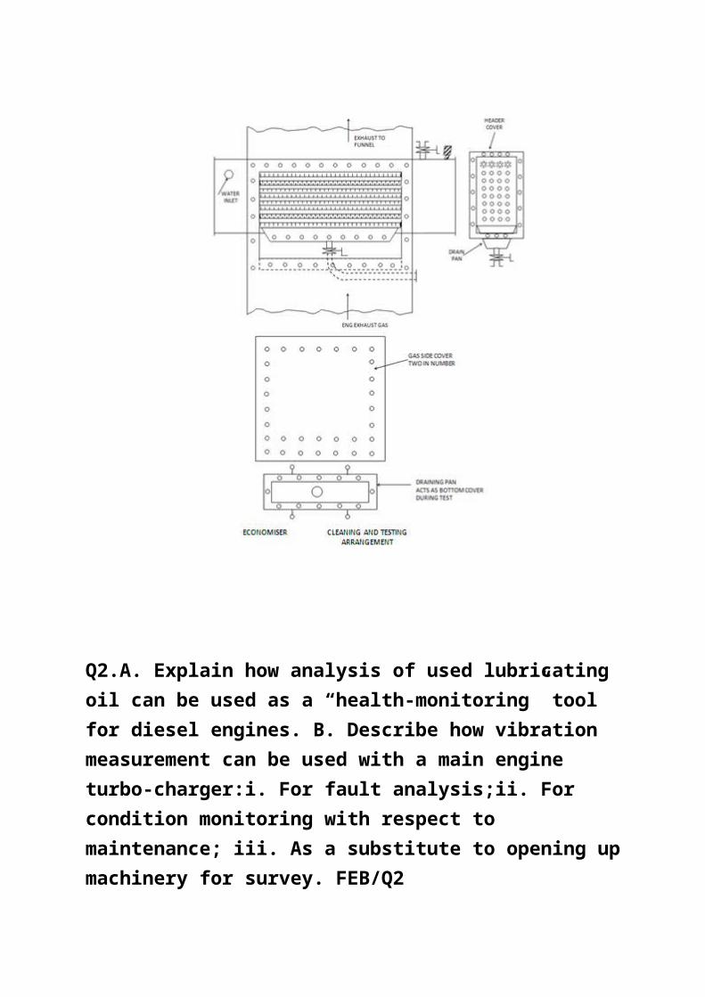
Washing procedure:- The casing covers were opened and the wash tray fitted in place. Using the fire hose and sea water connected to the hydrant in engine room, the finned tubes were thoroughly hosed with sea water till the fins were cleared of all the oily soot which had caked in between the fins of the tubes.. A final hosing down with fresh water was carried out to rinse the tubes of any salt adhering to the surface of the tubes.
Testing procedure :- The casing plates were fitted with new joints and the drain valve on the wash tray kept shut. Fresh water was filled to the top of the tubes through the inspection door in the casing plate . The inspection doors on the water and steam boxes were opened. Four tubes were found leaking, which were plugged using brass taper plugs made on board. Before fitting the casing doors finally, a leak test was carried out by circulating water from the boiler back to boiler using the circulating pump and no leaks found.
Commissioning and floating the safety valves:- The ship left the port of Durban on 20th October 2012. When full away was rung, the engine speed raised to the full sea load condition. The safety valves were already overhauled and fitted without the easing gear for setting of the valves. The port valve was kept gagged ready for setting. When engine speed came up to the full sea load condition ,the pressure was rose up quickly inside the steam box as the steam stop valve was kept shut. With slight adjustment of the compression nut the valve was set at the pressure of 6.5 bar as recommended in the manual. The gagging
tool was transferred to the starboard valve and the operation repeated. The flow of steam through the waste steam pipe noted and the accumulation of pressure was only 0.1 bar. The easing gear of the valves connected and the safety valves are now in operational mode. The boiler is not being fired now.
For your ready reference the cleaning and testing rig is shown in sketch.
Q2.A. Explain how analysis of used lubricating oil can be used as a “health-monitoring” tool for diesel engines. B. Describe how
vibration measurement can be used with a main engine turbo-charger:i. For fault analysis;ii. For condition monitoring with respect to maintenance; iii. As a substitute to opening up machinery for survey. FEB/Q2
Answer:- The peruiodical laboratory testing and analysis of used lub oil is an established practice followed by most of the shipping companies
The benefits achieved by this process are:
It tells us whether the filters in the luboil system are working satisfactorily olr otherwise.
It shows whether the purification of the oil by removing the water is effective
It also gives evoidence of foreign matter in the oil such as metal particles of iron, copper aluminium etc which gives an indication of both poor filtration as well as bearing wear and so warns the ship staff on monitoring the condition of suspected bearings and condition of the magnetic filtersk
Finally it is an advisory report which recommends further corrective action which must be followed .
B
What is vibration analysis?
Vibration Analysis (VA) collects vibrations detected from equipment and measures them against known failure vibrations to identify potential failure points.
VA can help maintenance professionals proactively address performance issues before machines break on the job.
Why Vibration Analysis Matters
Vibration analysis’ ability to predict potential failures makes it a useful tool to plan maintenance, boost asset performance, and prevent unscheduled downtime. It is one of the tools in the predictive maintenance (PdM) tool kit.Vibration analysis helps conduct condition monitoring to identify potential failures, which ultimately saves money by:
1. Reducing unplanned downtime and scheduling work that fits an organization’s plans
2. Saving money by boosting product quality through equipment operating at designed performance levels
3. Eliminating wasted production costs while unplanned repairs are made
4. Delivering products on time with reliable equipment
Vibration Measurement Techniques
Implementing vibration analysis is only the first step in actually using and benefiting from this technique. The complete processes of vibration measurement techniques is described as follows:
Calculate the Vibration Spectrum
For most systems, you can measure various points on its vibration spectrum. Using this data, you can produce a model that illustrates expected vibration behavior.
Establish a BaselineIn order to take full advantage of your vibration data in your predictive maintenance program, you must establish baseline data to inform your condition monitoring. There are normal levels of vibration and acceptable variations that do not indicate failure. Baseline data will set parameters around what performance is acceptables in order to make abnormalities clear.
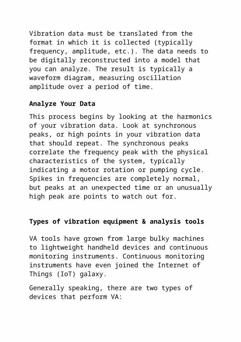
Generate Signal ModelsVibration data must be translated from the format in which it is collected (typically frequency, amplitude, etc.). The data needs to be digitally reconstructed into a model that you can analyze. The result is typically a waveform diagram, measuring oscillation amplitude over a period of time.
Analyze Your DataThis process begins by looking at the harmonics of your vibration data. Look at synchronous peaks, or high points in your vibration data that should repeat. The synchronous peaks correlate the frequency peak with the physical characteristics of the system, typically indicating a motor rotation or pumping cycle. Spikes in frequencies are completely normal, but peaks at an unexpected time or an unusually high peak are points to watch out for.
Types of vibration equipment & analysis tools
VA tools have grown from large bulky machines to lightweight handheld devices and continuous monitoring instruments. Continuous monitoring instruments have even joined the Internet of Things (IoT) galaxy.Generally speaking, there are two types of devices that perform VA:
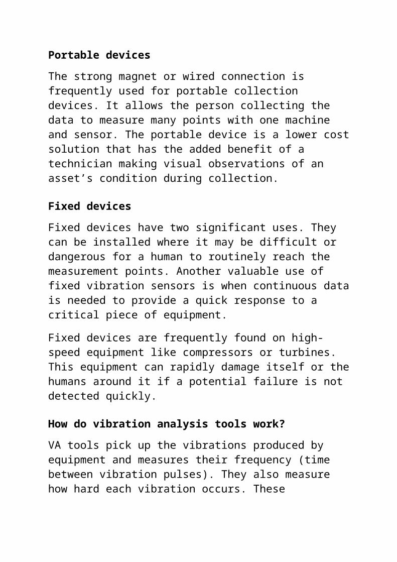
Portable devicesThe strong magnet or wired connection is frequently used for portable collection devices. It allows the person collecting the data to measure many points with one machine and sensor. The portable device is a lower cost solution that has the added benefit of a technician making visual observations of an asset’s condition during collection.
Fixed devicesFixed devices have two significant uses. They can be installed where it may be difficult or dangerous for a human to routinely reach the measurement points. Another valuable use of fixed vibration sensors is when continuous data is needed to provide a quick response to a critical piece of equipment.Fixed devices are frequently found on high-speed equipment like compressors or turbines. This equipment can rapidly damage itself or the humans around it if a potential failure is not detected quickly.
How do vibration analysis tools work?VA tools pick up the vibrations produced by equipment and measures their frequency (time between vibration pulses). They also measure how hard each vibration
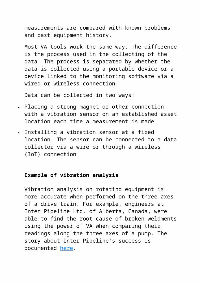
occurs. These measurements are compared with known problems and past equipment history.Most VA tools work the same way. The difference is the process used in the collecting of the data. The process is separated by whether the data is collected using a portable device or a device linked to the monitoring software via a wired or wireless connection.Data can be collected in two ways:
Placing a strong magnet or other connection with a vibration sensor on an established asset location each time a measurement is made
Installing a vibration sensor at a fixed location. The sensor can be connected to a data collector via a wire or through a wireless (IoT) connection
Example of vibration analysis
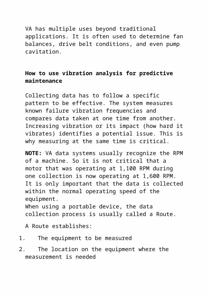
Vibration analysis on rotating equipment is more accurate when performed on the three axes of a drive train. For example, engineers at Inter Pipeline Ltd. of Alberta, Canada, were able to find the root cause of broken weldments using the power of VA when comparing their readings along the three axes of a pump. The story about Inter Pipeline’s success is documented here.VA has multiple uses beyond traditional applications. It is often used to determine fan balances, drive belt conditions, and even pump cavitation.
How to use vibration analysis for predictive maintenance
Collecting data has to follow a specific pattern to be effective. The system measures known failure vibration frequencies and compares data taken at one time from another. Increasing vibration or its impact (how hard it vibrates) identifies a potential issue. This is why measuring at the same time is critical.NOTE: VA data systems usually recognize the RPM of a machine. So it is not critical that a motor that was operating at 1,100 RPM during one collection is now operating at 1,600 RPM. It is only important that the data is collected within the normal operating speed of the equipment.When using a portable device, the data collection process is usually called a Route.A Route establishes:
1. The equipment to be measured2. The location on the equipment where the measurement
is needed3. The types of tests required at each location
The data collected during the route is loaded into the VA database. The VA software helps to identify irregularities from previous data or is outside of a set parameter. (Rockwell offers a wide variety of VA solutions.)The VA technician can take additional measurements and/or report the findings on a follow-up work order in the computerized maintenance management system (CMMS). The specific component requiring replacement or service can be made a part of the follow-up work if the technician is confident of the necessary next steps.
Benefits of Vibration Analysis
Vibration analysis is one of the most versatile tools in predictive maintenance programs. Some of the benefits for using vibration analysis to help you with data collection are:
VA has a long history with a proven track record for reliability
The potential for failure can be readily identified Data can be collected by anyone A portable collection route can be rapidly established There are multiple uses of VA beyond the most
prevalent bearing failure search
Q3. With regards to main transmission shaft flange coupling arrangements: A. Sketch a hollow type coupling bolt and the hydraulic head/nut and loading rod which are used to fit it;B. Describe how the bolt is fitted; C. State the advantage of the hollow coupling bolt as compared to the traditional type of coupling bolt.2017/JUL 2018/JAN 2018/JULY 2019/JUN 2020/FEB/Q3
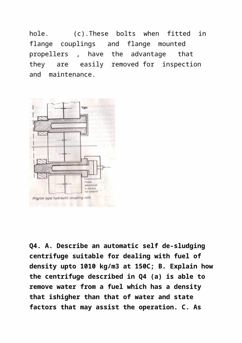
Answer:- (b) The Pilgrim hydraulic bolt uses the principle embodied in Poisson’s ratio to provide a calculated and definite fitting force between bolt and hole .The bolt is hollow and before being fitted is stretched with hydraulic pressure applied to an inserted rod from a pressure cylinder screwed to the bolt head. Stretching makes the bolt diameter small enough for insertion into the hole , after which the nut is nipped up. Release of hydraulic pressure allows the bolt to shorten so that (1)predetermined bolt load is produced and (2) diametrical reexpansion gives a good fit of the shank in the hole.
(c).These bolts when fitted in flange couplings and flange
mounted propellers , have the advantage that they are easily removed for inspection and maintenance.
Q4. A. Describe an automatic self de-sludging centrifuge suitable for dealing with fuel of density upto 1010 kg/m3 at 150C; B. Explain how the centrifuge described in Q4 (a) is able to remove water from a fuel which has a density that ishigher than that of water and state factors that may assist the operation. C. As Second Engineer, write down the start-up procedure for the centrifuge described in Q1 (a) for the benefit of your staff;D. State how the problem of catalytic fines in fuel oil may be dealt with. 2020/FEB/Q4
Answer:- (a and b ) The Alfa-Laval design of centrifuge intended for dealing with high density residual fuels is a self sludging machine which has a flow control disc that makes it virtually a
clarifier. There are no gravity discs to be changed to make the machine suitable for fuels of different sp/gr. Heating is used to reduce the density(and viscosity) of the fuel so that water and sludge accumulate in the outer part of the bowl ,as the result of the centrifugal effect. As the interface moves inwards, but before reaching the disc stack, water droplets flow through to reach a water sensing transducer via microprocessor circuitry. The transducer causes the bowl to self sludge or the water to be discharged through the water drain valve. The system is said to be capable of handling fuels with densities as high as 1010kg/m3 at 150 C.
(c)The start-up procedure is as follows:-
(1) Ensure and confirm that the bowl brakes /stoppers are disengaged and the bowl can turn freely.
(2) Switch on the centrifuge and allow it to gain speed till the speed gauge / indicator shows that the sped is attained.
(3) Open the water to build up the water wall and this will be noticed by the flow of water through the water discharge
(4) Control the water flow till it is only a small trickle seen through the water discharge .
(5) Circulate the fuel oil through thee heater till the temperature reaches the desired value.
(6) Control the fuel oil inlet to the centrifuge by throttling the oil inlet valve to give a flow of oil as desired.
The centrifuge efficiency is inversely proportional to throughput and hence the throughput should be so adjusted that it fills up the service tank at the required time interval.
The catalytic fines are very small particles of the catalyst used in the refining process to obtain higher derivatives from crude. By this process the refining efficiency is increased so that the residual crude contains mainly carbon, asphaltic and bituminous substances. The catalytic fines remain in this residual crude mixture and they are to be removed by clarifying. Hence the oil must be refined by operating the separator as purifier and clarifier connected in series and reducing the throughput . This will ensure that the catalytic fines are dealt with
Q5. A. Explain why centrifugal pumps cannot handle air or vapours to effect priming yet turbo- blowers operating on the same principle can.B. If a vessel is fully laden, how may it be ascertained that the fire pump priming arrangements would operate satisfactorily in the ballast condition. C. Explain a method of priming suitable for a centrifugal pump.JAN 2018/JAN 2020/FEB/Q5
Answer:- A centrifugal pump is designed only to handle liquids and hence its speed of rotation is designed to suit the density and viscosity of the liquid,. Its speed has therefore got to be low to deal with a heavier substance like liquid as compared to
air. Whereas a turbo blower which is a rotary air compressor is only dealing with air and its designed speed of rotation of the impeller is therefore much higher than the speed of rotation of the impeller of the centrifugal pump. Hence the centrifugal pump cannot handle any air trapped in the water and therefore needs a special priming device.
(b)If the pump suction is fitted with a connection leading to a suitable water gauge or a compound pressure gauge , the absolute value of the suction pressure can be determined by running the pump with the foot valve at the sea suction shut and by reading the absolute pressure. If it registers about 0.2 kg/cm2 it is very good and it has the capacity to operate successfully in the ballast condition( 0.2kg/cm2= -0.8kg/cm2 gauge.
(c)
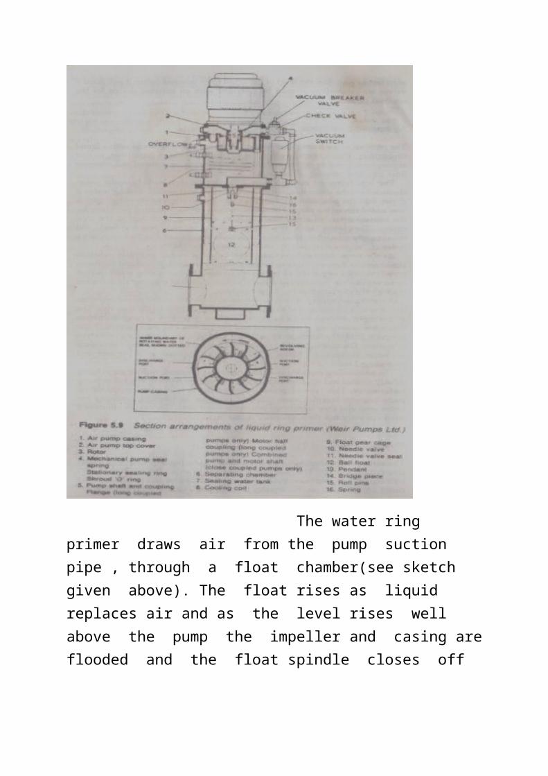
The water ring primer draws air from the pump suction pipe , through a float chamber(see sketch given above). The float rises as liquid replaces air and as the level rises well above the pump the impeller and casing are flooded and the float spindle closes off the suction. This ensures that the primer itself is not flooded.
Q6. With reference to hydraulic steering gears, sketch and describe each of the following: (A)Single failure concept; (B)100% redundancy. 2020/FEB/Q6
Answer:- - (1) The single failure concept was developed with the advent of large crude oil carriers above 100,000 tons DWT and large passenger ships.
According to this concept , if the steering gear fails for any single failure of the pump ,motor or pipe leakage , The stand by steering gear pump set will come on load within 45 seconds of the failure In this system pipe interconnections are there and the change over is automatically accomplished with the right combination of the inter connections. The failure of the rudder stock is not considered since the failure of rudder stock is not probable.

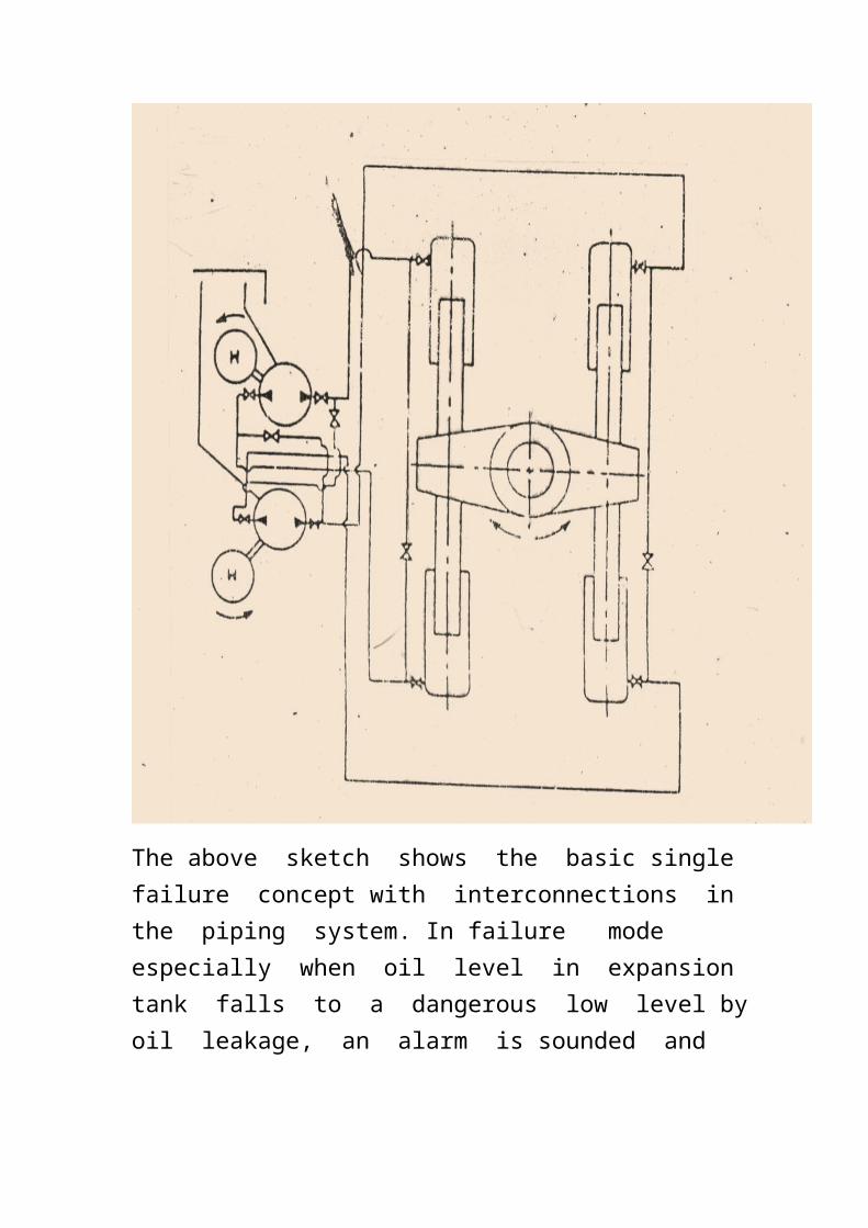
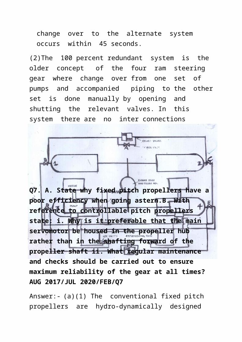
The above sketch shows the basic single failure concept with interconnections in the piping system. In failure mode especially when oil level in expansion tank falls to a dangerous low level by oil leakage, an alarm is sounded and change over to the alternate system occurs within 45 seconds.
(2)The 100 percent redundant system is the older concept of the four ram steering gear where change over from one set of
pumps and accompanied piping to the other set is done manually by opening and shutting the relevant valves. In this system there are no inter connections
Q7. A. State why fixed pitch propellers have a poor efficiency when going astern.B. With reference to controllable pitch propellers state: i. Why is it preferable that the main servomotor be housed in the propeller hub rather than in the shafting forward of the propeller shaft ii. What regular maintenance and checks should be carried out to ensure maximum reliability of the gear at all times?AUG 2017/JUL 2020/FEB/Q7
Answer:- (a)(1) The conventional fixed pitch propellers are hydro-dynamically designed only for the driving face which is active in the ahead direction. Hence the propeller efficiency is best in the ahead direction.
(2)When going astern the wake direction is forward and the flow of the wake is resisted by the underwater stern hull portion. Hence propulsive efficiency is reduced.
(b) The main servomotor for changing the pitch of the propeller is cylinder with a piston arranged within the shaft system. The piston is connected to the pitch actuating gear by the piston rod. If it is placed within the propeller shaft it reduces the piston rod length considerably and ensures oil tightness restricted within the propeller shaft. If it is placed in the
intermediate shaft the design gets more complicated as can be seen in the concept sketch given below.
(2) The regular maintenance required in every dry docking is the Oil seals of the individual blade connection to the actuating X-head connection is renewed and the actuating mechanism is dismantled , inspected and worn parts are renewed.

Q8. A. Describe a transverse bow thrust unit using CPP, mention how it should be made to support and how the strength of thrust and reverse thrust are achieved; B. State with reasons, a suitable prime mover for the controllable pitch propeller; C. State whether the thrust unit delivers a relatively low pressure head with high volume output or high pressure head with low volume output. 2018/JAN 2018/JULY 2020/FEB/Q8
Answer:- The bow thruster unit is normally fitted in a circular ducting at the lower portion (under water) of the forepeak tank with a water tight fat above the ducting where the driving motor is placed. The drive is through a vertical and horizontal drive shafts with suitable gearing and inbuilt thrust collar with thrust pads.
The heavy thrust is created by a an axial flow impeller or propeller within the ducting and the thrust strength is varied by changing the pitch angle , which is controlled hydraulically.. The thrust is reversed by changing the pitch through about ninty degrees , when reverse flow is achieved. The thrust unit is very useful in berthing operations of large ships and can eliminate the need of tugs to pull the ship off the pier. The sketches showing the thrusters unit and the pitch control are also shown under.

The pitch is controlled by a ward-leonard positioning system with a negative feed back arranged outside the shafting. The sketch of the control system is given as under.
(b)The best suited prime mover for this unit would be a double squirrel cage motor. This motor is compact and will not require a large space. Being a n electric motor it does not need any cooling device like a diesel engine. Load variation for varying the thrust is easily provided by the double cage motor because of the second layer of copper conductors in the cage which allow for the increase in load current when operating for higher thrusts.
(c)The propeller is like an axial flow impeller . Hence it delivers a high mass output with low pressure.
Q9. Reverse osmosis is the modern alternative for shipboard production of drinking water. A. Describe using simple diagrams if necessary, the principle of reverse osmosis. B. Sketch a line diagram showing a single pass system for producing fresh water from sea water and Describe such a system. 2018/JAN 2018/JULY 2018/OCT 2018/NOV 2019/APR 2019/JULY 2019/AUG
Answer:- Reverse osmosis (RO) is a water purification technology that uses a semi-permeable membrane to remove ions, molecules, and larger particles from drinking water. In reverse osmosis, an applied pressure is used to overcome osmotic pressure, a colligative
property, that is driven by chemical potential differences of the solvent, a thermodynamic parameter. Reverse osmosis can remove many types of dissolved and suspended species from water, including bacteria, and is used in both industrial processes and the production of potable water. The result is that the solute is retained on the pressurized side of the membrane and the pure solvent is allowed to pass to the other side. To be "selective", this membrane should not allow large molecules or ions through the pores (holes), but should allow smaller components of the solution (such as solvent molecules) to pass freely.
In the normal osmosis process, the solvent naturally moves from an area of low solute concentration (high water potential), through a membrane, to an area of high solute concentration (low water potential). The driving force for the movement of the solvent is the reduction in the free energy of the system when the difference in solvent concentration on either side of a membrane is reduced, generating osmotic pressure due to the solvent moving into the more concentrated solution. Applying an external pressure to reverse the natural flow of pure solvent, thus, is reverse osmosis. The process is similar to other membrane technology applications. However, key differences are found between reverse osmosis and filtration. The predominant removal mechanism in membrane filtration is straining, or size exclusion, so the process can theoretically achieve perfect efficiency regardless of parameters such as the solution's pressure and concentration. Reverse osmosis also involves diffusion, making the process dependent on pressure, flow rate, and other conditions.[1] Reverse osmosis is most commonly known for its use in drinking water purification from seawater, removing the salt and other effluent materials from the water molecules.(The above explanation need not be written in the answer. Itis given only for understanding the phenomenon.).)
The above diagram exhibits the principle of reverse osmosis. When sea water is made to pass through a semi permeable membrane , at high pressure the salts dissolved in the sea water is prevented from passing through the membrane and only pure fresh water is obtained on the other side of the membrane. Hence it is a form of filtration of dissolved salts from water.