Embed Size (px)
Citation preview
NorDig Unified Test plan, ver 2.6.0
Draft update for NorDig Test Plan spec. v. 3.1
Draft v002
NorDig Unified Test Plan for
Integrated Receiver Decoders
for use in cable, satellite, terrestrial and IP-based networks
Date: dd.mm.yyyy
Following text is only during drafting and will be removed before final NorDig IRD specification
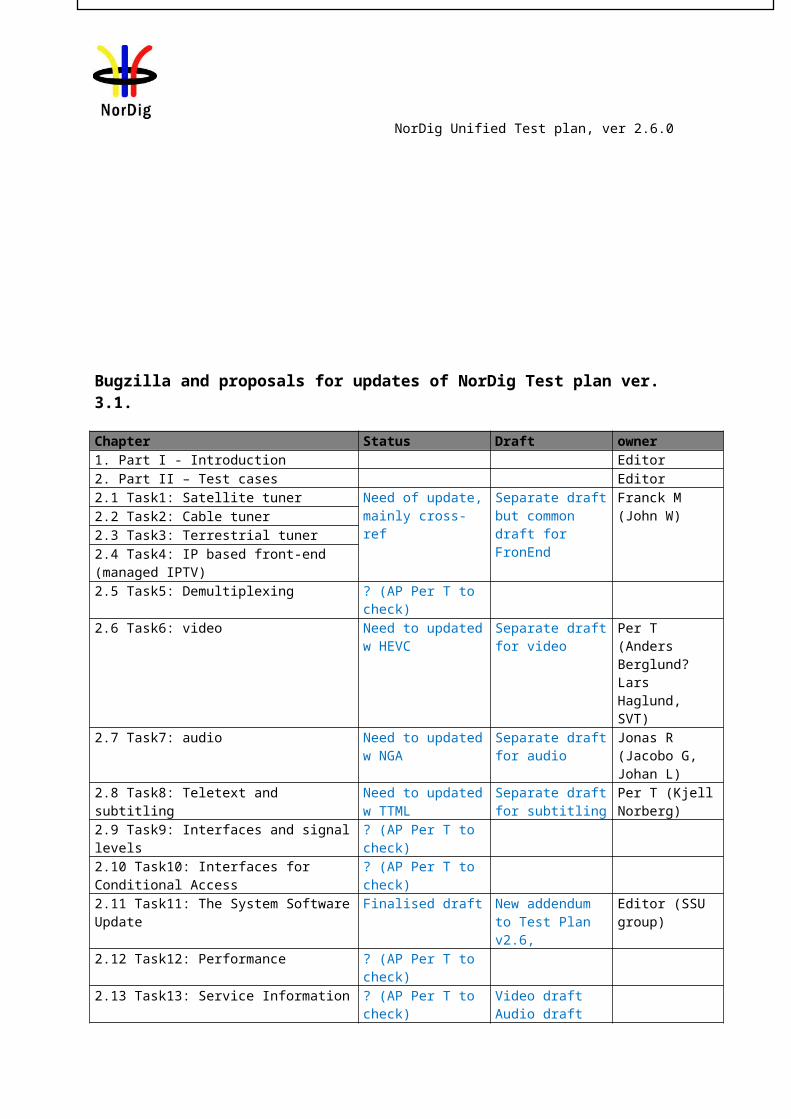
Bugzilla and proposals for updates of NorDig Test plan ver. 3.1.
Chapter Status Draft owner
DRAFTING GUIDELINES / Explanation from the editors related to DRAFT versions:This NorDig Unified Test Plan spec. for v3.1 draft document is based on the official NorDig Unified Test Plan v2.6.0
Yellow highlight marking marks changes in text compared to NorDig Unified Test Plan v2.6.0o New modified text: without strikethrough marks new additional text, o Removed text: with strikethrough marks old text proposed to be removed
Green marked text: highlighting text that under extra scrutiny during this update (not yet agreed). Blue marked text: comments or other raw text that will be removed before final version. Grey marked text: refers to text that not are relevant to this review/update (SSU).
Guide: To improve version handling and readability, old text from NorDig Unified Test Plan v2.6.0 that is proposed to be deleted in future “v3.1” should not be removed from draft version.
Use instead strikethrough and yellow highlighted marking. Microsoft Word function “Track Changes”, will be used in addition to highlight changes, BUT from one draft version to another draft sometimes all “Track Changes” are
Accepted to easier read changes in updates of proposals during our work.
When drafting a proposal, cross-references should be manually set and same for proposing correction, i.e. yellow mark
NorDig Unified Test plan, ver 2.6.0
1. Part I - Introduction Editor2. Part II – Test cases Editor2.1 Task1: Satellite tuner Need of update,
mainly cross-refSeparate draft but common draft for FronEnd
Franck M (John W)2.2 Task2: Cable tuner
2.3 Task3: Terrestrial tuner2.4 Task4: IP based front-end (managed IPTV)2.5 Task5: Demultiplexing ? (AP Per T to check)2.6 Task6: video Need to updated w
HEVCSeparate draft for video
Per T (Anders Berglund? Lars Haglund, SVT)
2.7 Task7: audio Need to updated w NGA
Separate draft for audio
Jonas R (Jacobo G, Johan L)
2.8 Task8: Teletext and subtitling Need to updated w TTML
Separate draft for subtitling
Per T (Kjell Norberg)
2.9 Task9: Interfaces and signal levels ? (AP Per T to check)2.10 Task10: Interfaces for Conditional Access ? (AP Per T to check)2.11 Task11: The System Software Update Finalised draft New addendum to
Test Plan v2.6, Editor (SSU group)
2.12 Task12: Performance ? (AP Per T to check)2.13 Task13: Service Information ? (AP Per T to check)
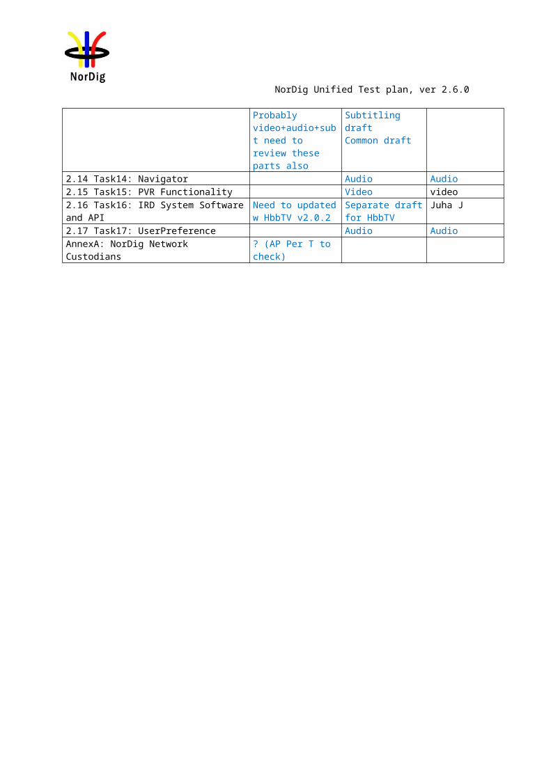
Probably video+audio+subt need to review these parts also
Video draftAudio draftSubtitling draftCommon draft
2.14 Task14: Navigator Audio Audio2.15 Task15: PVR Functionality Video video2.16 Task16: IRD System Software and API Need to updated w
HbbTV v2.0.2Separate draft for HbbTV
Juha J
2.17 Task17: UserPreference Audio AudioAnnexA: NorDig Network Custodians ? (AP Per T to check)
()
1 draft v002
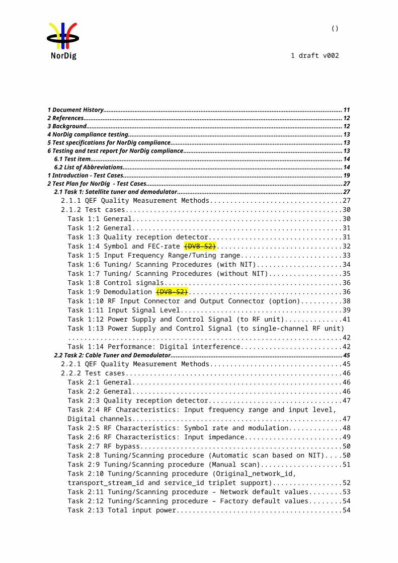
1 Document History..............................................................................................................................................112 References..........................................................................................................................................................123 Background........................................................................................................................................................124 NorDig compliance testing................................................................................................................................135 Test specifications for NorDig compliance.....................................................................................................136 Testing and test report for NorDig compliance...............................................................................................13
6.1 Test item.......................................................................................................................................................146.2 List of Abbreviations...................................................................................................................................14
1 Introduction - Test Cases..................................................................................................................................192 Test Plan for NorDig - Test Cases...................................................................................................................27
2.1 Task 1: Satellite tuner and demodulator...................................................................................................272.1.1 QEF Quality Measurement Methods.....................................................................................................272.1.2 Test cases...............................................................................................................................................30
Task 1:1 General.........................................................................................................................................30Task 1:2 General.........................................................................................................................................31Task 1:3 Quality reception detector............................................................................................................31Task 1:4 Symbol and FEC-rate (DVB-S2).................................................................................................32Task 1:5 Input Frequency Range/Tuning range..........................................................................................33Task 1:6 Tuning/ Scanning Procedures (with NIT)....................................................................................34Task 1:7 Tuning/ Scanning Procedures (without NIT)...............................................................................35Task 1:8 Control signals.............................................................................................................................36Task 1:9 Demodulation (DVB-S2).............................................................................................................36Task 1:10 RF Input Connector and Output Connector (option).................................................................38Task 1:11 Input Signal Level......................................................................................................................39Task 1:12 Power Supply and Control Signal (to RF unit)..........................................................................41Task 1:13 Power Supply and Control Signal (to single-channel RF unit)..................................................42Task 1:14 Performance: Digital interference..............................................................................................42
2.2 Task 2: Cable Tuner and Demodulator......................................................................................................452.2.1 QEF Quality Measurement Methods.....................................................................................................452.2.2 Test cases...............................................................................................................................................46
Task 2:1 General.........................................................................................................................................46Task 2:2 General.........................................................................................................................................46Task 2:3 Quality reception detector............................................................................................................47Task 2:4 RF Characteristics: Input frequency range and input level, Digital channels..............................47Task 2:5 RF Characteristics: Symbol rate and modulation.........................................................................48Task 2:6 RF Characteristics: Input impedance...........................................................................................49Task 2:7 RF bypass.....................................................................................................................................50Task 2:8 Tuning/Scanning procedure (Automatic scan based on NIT)......................................................50Task 2:9 Tuning/Scanning procedure (Manual scan).................................................................................51Task 2:10 Tuning/Scanning procedure (Original_network_id, transport_stream_id and service_id triplet support).......................................................................................................................................................52Task 2:11 Tuning/Scanning procedure – Network default values..............................................................53Task 2:12 Tuning/Scanning procedure – Factory default values................................................................54Task 2:13 Total input power.......................................................................................................................54Task 2:14 RF Performance - C/N for Reference BER................................................................................55Task 2:15 RF Performace - C/N with echo.................................................................................................56Task 2:16 Performance Data: Noise figure.................................................................................................58Task 2:17 RF Performance - Image Channel..............................................................................................60Task 2:18 RF Performance – Digital Adjacent Channel.............................................................................61Task 2:19 RF Performance – Analog Adjacent Channel............................................................................62Task 2:20 LO leakage.................................................................................................................................64Task 2:21 Spurious emission......................................................................................................................64Task 2:22 Radiation....................................................................................................................................65
2.3 Task 3: Terrestrial Tuner and Demodulator..............................................................................................662.3.1 Test equipment summary.......................................................................................................................66
()
1 draft v002
2.3.2 QEF Quality Measurement Methods.....................................................................................................662.3.3 Bitrates...................................................................................................................................................792.3.4 Receiver operability in SFN...................................................................................................................812.3.5 0dB echo................................................................................................................................................812.3.6 Conditions for analoque TV...................................................................................................................812.3.7 Summary of DVB-T2 modes in DVB-T2 test tasks..............................................................................822.3.8 Stream packet structure in Receiver Buffer Model (RBM) tests for DVB-T2......................................892.3.9 Test cases...............................................................................................................................................91
2.3.9.1 Test cases – DVB-T IRD............................................................................................................91Task 3:1 General.........................................................................................................................................91Task 3:2 General.........................................................................................................................................91Task 3:3 Quality reception detector............................................................................................................92Task 3:4 Frequencies: Center frequencies..................................................................................................92Task 3:5 Frequencies: Frequency offset.....................................................................................................96Task 3:6 Frequencies: Signal bandwidths...................................................................................................97Task 3:7 Modes...........................................................................................................................................99Task 3:8 Tuning/Scanning Procedure: General........................................................................................100Task 3:9 Tuning/Scanning Procedures: Basic status check......................................................................101Task 3:10 Tuning/Scanning Procedures: Automatic channel search for the same service bouquet.........102Task 3:11 Tuning/Scanning: Automatic channel search for different service bouquets..........................107Task 3:12 Tuning/Scanning Procedures: Manual Channel Search...........................................................109Task 3:13 Verification of Signal Strength Indicator (SSI).......................................................................111Task 3:14 Verification of Signal Quality Indicator (SQI)........................................................................114Task 3:15 Changes In Modulation Parameters.........................................................................................118Task 3:16 RF input connector...................................................................................................................119Task 3:17 RF output connector.................................................................................................................120Task 3:18 Performance: BER vs C/N verification....................................................................................121Task 3:19 Performance: C/N performance on Gaussian channel.............................................................122Task 3:20 Performance: C/N performance on 0dB echo channel.............................................................125Task 3:21 Performance: Minimum receiver signal input levels on Gaussian channel.............................126Task 3:22 Performance: Minimum IRD Signal Input Levels on 0dB echo channel................................128Task 3:23 Performance: Noise figure on Gaussian channel.....................................................................131Task 3:24 Performance: Maximum Receiver Signal Input Levels...........................................................133Task 3:25 Performance: Immunity to “digital” signals in Other Channels..............................................134Task 3:26 Performance: Immunity to “LTE 700 MHz” signals in Other Channels.................................137Task 3:27 Performance: Immunity to “LTE 800 MHz” signals in Other Channels.................................139Task 3:28 Performance: Performance in Time-Varying Channels...........................................................141Task 3:29 Performance: Synchronisation for varying echo power levels in SFN....................................143Task 3:30 Performance: C/(N+I) Performance in SFN for more than one echo......................................144Task 3:31 Performance: C/(N+I) Performance in SFN inside the guard interval.....................................148Task 3:32 Performance: C/(N+I) Performance in SFN outside the guard interval...................................1542.3.9.2 Test cases – DVB-T2................................................................................................................156Task 3:33 DVB-T2: Frequencies: Center frequencies..............................................................................156Task 3:34 DVB-T2: Frequencies: Frequency offset.................................................................................160Task 3:35 DVB-T2: Frequencies: Signal bandwidths..............................................................................162Task 3:36 DVB-T2: Modes.......................................................................................................................164Task 3:37 DVB-T2: MISO.......................................................................................................................167Task 3:38 DVB-T2: Input Mode B (multiple PLPs).................................................................................170Task 3:39 DVB-T2: Input Mode B (multiple PLPs and common PLP)...................................................171Task 3:40 DVB-T2: Input Mode B (RBM for TDI).................................................................................172Task 3:41 DVB-T2: Input Mode B (RBM for DJB).................................................................................173Task 3:42 DVB-T2: Input Mode B (RBM when FEF present)................................................................175Task 3:43 DVB-T2: Normal mode (NM).................................................................................................177Task 3:44 DVB-T2: Input Mode A (zero power FEF present).................................................................178Task 3:45 DVB-T2: Input Mode A (RBM when FEF present)................................................................179Task 3:46 DVB-T2: Auxiliary streams.....................................................................................................181Task 3:47 DVB-T2: Reception of version 1.1.1.......................................................................................182
()
1 draft v002
Task 3:48 DVB-T2: Tuning/Scanning Procedures: Automatic channel search for the same service bouquet......................................................................................................................................................183Task 3:49 DVB-T2: Tuning/Scanning Procedures: Basic status check....................................................188Task 3:50 DVB-T2: Verification of Signal Strength Indicator (SSI).......................................................189Task 3:51 DVB-T2: Verification of Signal Quality Indicator (SQI)........................................................192Task 3:52 DVB-T2: Changes In Modulation Parameters.........................................................................196Task 3:53 DVB-T2: Time interleaving.....................................................................................................197Task 3:54 DVB-T2: Input/Output Data Formats......................................................................................198Task 3:55 DVB-T2: Performance: BER vs C/N verification...................................................................200Task 3:56 DVB-T2: Performance: C/N performance on Gaussian channel.............................................201Task 3:57 DVB-T2: Performance: C/N performance on 0dB echo channel............................................205Task 3:58 DVB-T2: Performance: Minimum receiver signal input levels on Gaussian channel.............206Task 3:59 DVB-T2: Performance: Minimum IRD Signal Input Levels on 0dB echo channel................211Task 3:60 DVB-T2: Performance: Receiver noise figure on Gaussian channel.......................................213Task 3:61 DVB-T2: Performance: Maximum Receiver Signal Input Levels...........................................215Task 3:62 DVB-T2: Performance: Immunity to “digital” signals in Other Channels..............................216Task 3:63 DVB-T2: Performance: Immunity to “LTE 700 MHz” signals in Other Channels.................220Task 3:64 DVB-T2: Performance: Immunity to “LTE 800 MHz” signals in Other Channels.................222Task 3:65 DVB-T2: Performance: Performance in Time-Varying Channels...........................................224Task 3:66 DVB-T2: Performance: Synchronisation for varying echo power levels in SFN....................227Task 3:67 DVB-T2: Performance: C/(N+I) Performance in SFN for more than one echo......................229Task 3:68 DVB-T2: Performance: C/(N+I) Performance in SFN inside the guard interval....................232Task 3:69 DVB-T2: Performance: C/(N+I) Performance in SFN outside the guard interval..................239
2.4 Task 4: IP-Based Front-end......................................................................................................................2412.5 Task 5: MPEG2 demultiplexer..................................................................................................................242
Task 5:1 SI utilization...............................................................................................................................242Task 5:2 CA descriptor interpretation.......................................................................................................242Task 5:3 Maximum transport stream data rate..........................................................................................242Task 5:4 Number of elementary streams..................................................................................................243Task 5:5 Section filtering..........................................................................................................................244Task 5:6 Variable Bitrate Elementary Streams.........................................................................................244Task 5:7 Mixture of SD and HD services.................................................................................................245Task 5:8 Descrambler Performance..........................................................................................................246Task 5:9 System clock recovery...............................................................................................................247
2.6 Task 6: Video.............................................................................................................................................248Task 6:1 Video Decoder - General...........................................................................................................248Task 6:2 Video Decoder – Resolutions and Frame rates..........................................................................249Task 6:3 Up-sampling/Up-conversion......................................................................................................250Task 6:4 Video Decoder - Colorimetry.....................................................................................................251Task 6:5 Video Decoder - Dynamic changes in video stream.................................................................252Task 6:6 Video Decoder - AVC still picture............................................................................................254Task 6:7 Minimum video bandwidth........................................................................................................255Task 6:8 Frame cropping..........................................................................................................................256Task 6:9 Overscan.....................................................................................................................................256Task 6:10 High Definition Video Output and Display.............................................................................257Task 6:11 Down-conversion of High Definition Video for Standard Definition output..........................257Task 6:12 16:9 displayed on 4:3 monitors................................................................................................258Task 6:13 Displaying 4:3 Material on 16:9 Monitors...............................................................................259Task 6:14 Rescaling for HbbTV application............................................................................................260
2.7 Task 7: Audio.............................................................................................................................................260Task 7:1 Audio User Preference Settings.................................................................................................260Task 7:2 MPEG-1 Layer II: Requirements...............................................................................................261Task 7:3 MPEG-1 Layer II: Analogue audio output.................................................................................261Task 7:4 MPEG-1 Layer II: HDMI output interface................................................................................262Task 7:5 MPEG-1 Layer II: S/PDIF output interface...............................................................................263Task 7:6 AC-3: Requirements...................................................................................................................264Task 7:7 AC-3: Analogue audio output....................................................................................................265Task 7:8 AC-3: HDMI output and HDMI ARC interface........................................................................266Task 7:9 AC-3: S/PDIF output interface...................................................................................................267
()
1 draft v002
Task 7:10 AC-3: Metadata........................................................................................................................269Task 7:11 E-AC-3: Requirements.............................................................................................................269Task 7:12 E-AC-3: Analogue audio output..............................................................................................270Task 7:13 E-AC-3: HDMI output and HDMI ARC interface..................................................................271Task 7:14 E-AC-3: S/PDIF output interface.............................................................................................272Task 7:15 E-AC-3: Metadata....................................................................................................................274Task 7:16 HE AAC: Requirements...........................................................................................................275Task 7:17 HE AAC: Analogue audio output............................................................................................276Task 7:18 HE AAC: HDMI output and HDMI ARC interface................................................................277Task 7:19 HE AAC: S/PDIF output interface...........................................................................................279Task 7:20 HE AAC: Metadata..................................................................................................................280Task 7:21 Audio prioritizing - Audio language support...........................................................................281Task 7:22 Audio Prioritising – audio format and stream type..................................................................282Task 7:23 Audio Prioritising – audio type................................................................................................285Task 7:24 Audio Prioritising – audio format signaling missing...............................................................287Task 7:25 Audio video synchronization...................................................................................................288Task 7:26 Adjustement of Video/audio-delay..........................................................................................290Task 7:27 Audio handling when changing service or audio format.........................................................291Task 7:28 Dynamic changes in audio components...................................................................................292Task 7:29 Audio descriptors.....................................................................................................................293Task 7:30 Clean audio...............................................................................................................................294Task 7:31 Supplementary audio................................................................................................................294Task 7:32 IRD Internal Reference Level..................................................................................................295Task 7:33 Loudness levels - Audio Output Levels...................................................................................296Task 7:34 AC-4: Requirements.................................................................................................................298Task 7:35 AC-4: Analogue audio output..................................................................................................299Task 7:36 AC-4: HDMI output and HDMI ARC interface......................................................................300Task 7:37 AC-4: S/PDIF output interface.................................................................................................301Task 7:38 Dialogue Enhancement............................................................................................................302Task 7:39 Audio prioritisation for NGA capable NorDig HEVC IRDs...................................................303Task 7:40 Audio prioritisation for NGA capable NorDig HEVC IRDs...................................................305Task 7:41 Audio Prioritisation inside the NGA Audio PID/stream..........................................................306
2.8 Task 8: Teletext and subtitling.................................................................................................................309Task 8:1 Subtitling - user preferences.......................................................................................................309Task 8:2 Subtitling - Only display subtitling if match language in user preferences...............................309Task 8:3 Subtitling - Temporary changes to subtitling settings................................................................310Task 8:4 Subtitling – Subtitling mode (Normal and Hard of hearing subtitling).....................................311Task 8:5 Subtitling – DVB Subtitling and subtitling priority (DVB/EBU)..............................................312Task 8:6 Teletext - Simultaneous EBU Teletext and HbbTV Digital Teletext........................................314Task 8:7 Subtitling - coexistent with HbbTV applications......................................................................315Task 8:8 Teletext – EBU Teletext level 1.5..............................................................................................316Task 8:9 Teletext - decoding method(VBI).............................................................................................316Task 8:10 Teletext decoding method(OSD).............................................................................................317Task 8:11 Teletext – teletext pages...........................................................................................................318Task 8:12 Teletext – teletext pages - cache..............................................................................................319Task 8:13 Subtitling – teletext subtitling..................................................................................................320Task 8:14 Subtitling – DVB Subtitling.....................................................................................................322
2.9 Task 9: Interfaces and Signal Levels......................................................................................................324Task 9:1 Two-way Interface.....................................................................................................................324Task 9:2 SCART Interface........................................................................................................................324Task 9:3 HDMI interface – HD Ready.....................................................................................................325Task 9:4 HDMI interface – EDID information.........................................................................................326Task 9:5 HDMI interface – Original format.............................................................................................327Task 9:6 HDMI – Manual setting for resolution.......................................................................................328Task 9:7 HDMI – Signal protection..........................................................................................................328Task 9:8 Analogue video interface(Option)..............................................................................................330Task 9:9 Remote Control Function Keys..................................................................................................331Task 9:10 Remote Control Function Keys for PVR.................................................................................331
()
1 draft v002
Task 9:11 Remote Control Key event mapping for NorDig Hybrid.........................................................3322.10 Task 10: Interfaces for Conditional Access..........................................................................................334
Task 10:1 Use of Common Interface........................................................................................................334Task 10:2 Smart Card Interface................................................................................................................334
2.11 Task 11: The System Software Update.................................................................................................3352.11.1 SSU testing General...........................................................................................................................3352.11.2 Test equipment summary...................................................................................................................335
2.11.2.1 Broadcast SSU (OTA)..........................................................................................................3362.11.2.2 Network SSU........................................................................................................................338
2.11.3 Test cases...........................................................................................................................................338Task 11:1 IRD System software update using DVB SSU simple profile.................................................338Task 11:2 IRD System software update using DVB SSU enhanced profile - scheduling........................341Task 11:3 IRD System software update using DVB SSU Notification....................................................345Task 11:4 IRD System software update using over-the-network download............................................347Task 11:5 IRD System software update using USB update......................................................................350Task 11:6 SSU end user functionality......................................................................................................352Task 11:7 Common interface plus (CI+) CAM module system software update.....................................354
2.12 Task 13: Service Information.................................................................................................................3562.12.1 General...............................................................................................................................................356
Task 11:1 SI: General...............................................................................................................................356Task 11:2 SI: General – Undefined data structures..................................................................................356Task 11:3 SI: General – ‘Actual’ and ‘Other’ tables................................................................................357Task 11:4 SI: SI data available through an API........................................................................................357Task 11:5 SI: Text strings and field size of the SI descriptor...................................................................357
2.12.2 Static PSI/SI data...............................................................................................................................358Task 11:6 NIT_actual – frequency_list_descriptor...................................................................................358Task 11:7 NIT_actual – Missing terrestrial_system_delivery_descriptor................................................360Task 11:8 NIT_actual – Missing T2_delivery_system_descriptor...........................................................361Task 11:9 SDT_actual service_descriptor and CA_identifier_descriptor................................................362
2.12.3 Quasi static PSI/SI data......................................................................................................................364Task 11:10 Quasi static update of SDT_actual.........................................................................................364Task 11:11 Quasi-static update of SDT_actual – linkage to NorDig simulcast replacement service.......364Task 11:12 Quasi-static update of NIT_actual – Linkage to an information service about the network. 366Task 11:13 Quasi-static update of NIT_actual – Linkage to EPG service...............................................367Task 11:14 Quasi-static update of NIT_actual – Linkage to TS that carriers EIT sch information for all services......................................................................................................................................................369Task 11:15 Quasi-static update of NIT_actual – Linkage to System Software Download service..........369
2.12.4 Dynamic PSI/SI data..........................................................................................................................369Task 11:16 Dynamic update of SDT_actual running status and linkage to a service replacement service...................................................................................................................................................................369Task 11:17 Dynamic update of EIT actual/other p/f.................................................................................371Task 11:18 Dynamic update of EIT_actual p/f CA_identifier_descriptor................................................372Task 11:19 Dynamic update of EIT actual/other p/f short_event_descriptor, extended_event_descriptor and content_descriptor..............................................................................................................................373Task 11:20 Dynamic update of EIT actual/other p/f content descriptor and component_descriptor.......375Task 11:21 Dynamic update of EIT actual/other p/f parental_rating_descriptor.....................................376Task 11:22 Dynamic update of EIT actual/other p/f and schedule in ESG using linkage........................378Task 11:23 Dynamic update of EIT actual/other p/f and schedule in ESG..............................................380Task 11:24 PMT Descriptors - General....................................................................................................382Task 11:25 PMT Descriptors – teletext pages, teletext subtitling and DVB subtitling............................383Task 11:26 Dynamic update of PMT PID values.....................................................................................384Task 11:27 Dynamic update of PMT-Component priority (stream type).................................................385Task 11:28 Dynamic update of PMT - Content_Protection_descriptor...................................................387Task 11:29 Dynamic update of TDT/TOT...............................................................................................388
2.13 Task 14: Navigator..................................................................................................................................392Task 12:1 Navigator: General...................................................................................................................392
2.13.1 Static PSI/SI data...............................................................................................................................393Task 12:2 Service list - General requirement............................................................................................393Task 12:3 Service list – service types and categories...............................................................................393
()
1 draft v002
Task 12:4 Service list – use of NIT_other and SDT_other.......................................................................395Task 12:5 Service list - Inconsistent of SDT_actual and NIT_actual information...................................397Task 12:6 Service list – NIT_actual interpretation...................................................................................398Task 12:7 Service list – NIT_actual original_network_ID.......................................................................399Task 12:8 Service list – NIT_actual network_ID.....................................................................................400Task 12:9 Service list – Inconsistent SDT_actual/NIT_actual and SDT_other/NIT_other......................401Task 12:10 Service list – Handling of multiple channel lists from same networks and NorDig LCD.....402Task 12:11 Service list – Simultaneous transmission of LCD v1 and v2.................................................405Task 12:12 Service list – Simultaneous reception of multiple networks and NorDig LCD.....................407Task 12:13 Service list - Priority of LCN between SD and HDTV services............................................408
2.13.2 Quasi static PSI/SI data......................................................................................................................411Task 12:14 Quasi-static update of service list – service addition.............................................................411Task 12:15 Quasi-static update of service list – non-visible data service addition..................................412Task 12:16 Quasi-static update of service list – services moved between different transport streams....414Task 12:17 Quasi-static update of service list – service remove..............................................................415Task 12:18 Quasi-static update of service list from NIT_actual for non-existing multiplexers...............417Task 12:19 Quasi-static update of service list from NIT_actual for removing a multiplex.....................419Task 12:20 Quasi-static update of NorDig LCN v1.................................................................................421Task 12:21 Quasi-static update of NorDig LCN v2.................................................................................423
2.14 Task 15: PVR Functionality....................................................................................................................426Task 13:1 Recording File System.............................................................................................................426Task 13:2 Recording capacity...................................................................................................................426Task 13:3 Deletion of the recordings........................................................................................................427Task 13:4 Failed and incomplete recordings............................................................................................427Task 13:5 File system intact after update..................................................................................................428Task 13:6 Limitations in recorded content – no extraction......................................................................429Task 13:7 Limitations in recorded content – downscaling of the HD content to the removable media...429Task 13:8 Disk Management....................................................................................................................430Task 13:9 General PVR recording – bitrates............................................................................................430Task 13:10 General PVR recording – service types.................................................................................431Task 13:11 ESG/EPG recording programming – individual events without CRID.................................433Task 13:12 ESG/EPG recording programming – individual event with CRID........................................434Task 13:13 ESG/EPG recording programming – individual event with CRID – same event recording..435Task 13:14 ESG/EPG recording programming – series...........................................................................435Task 13:15 Split recordings......................................................................................................................437Task 13:16 Split recordings- dynamic update of EIT...............................................................................438Task 13:17 Recommended events.............................................................................................................438Task 13:18 Alternative Recording............................................................................................................439Task 13:19 Accurate Recording – EIT information present.....................................................................440Task 13:20 Accurate Recording – EIT information missing....................................................................442Task 13:21 Accurate Recording – Loss of signal.....................................................................................443Task 13:22 Accurate Recording – EIT update in stand-by.......................................................................444Task 13:23 Simultaneous recording – OTR and viewing.........................................................................444Task 13:24 Simultaneous recording – Scheduled recording and viewing................................................445Task 13:25 Simultaneous recording – OTR and time-shift......................................................................446Task 13:26 Simultaneous recording – Scheduled recording and time-shift.............................................446Task 13:27 Simultaneous recording and playback...................................................................................447Task 13:28 Back-to-back recordings – Static EIT information................................................................448Task 13:29 Back-to-back recordings – Changes in EIT information.......................................................449Task 13:30 Timeshift recording................................................................................................................451Task 13:31 Manual recording...................................................................................................................452Task 13:32 Manual recording – Changes in TDT/TOT............................................................................453Task 13:33 One Touch Recording (OTR).................................................................................................454Task 13:34 Automatic Conflict Handling – During programming...........................................................455Task 13:35 Automatic Conflict Handling – After programming..............................................................456Task 13:36 Maximum length of recordings..............................................................................................457Task 13:37 Recording of parallel broadcast.............................................................................................458Task 13:38 Playback - General.................................................................................................................458
()
1 draft v002
Task 13:39 Replay/Playback – trick modes in playback..........................................................................459Task 13:40 Replay/Playback – trick modes in timeshift...........................................................................460Task 13:41 Relative synchronisation........................................................................................................461Task 13:42 Full service playback – Dynamic update of PMT audio language........................................462Task 13:43 Full service playback – Dynamic update of PMT audio format............................................464Task 13:44 Full service playback – Dynamic update of PMT audio type................................................465Task 13:45 Full service playback – Dynamic update of PMT subtitling language.................................467Task 13:46 Full service playback – Subtitling for the hard-of-hearing....................................................469Task 13:47 Full service playback – Dynamic update of PMT subtitling type..........................................470Task 13:48 Full service playback – Subtitling syncrhonization...............................................................471Task 13:49 Full service playback – Subtitling synchronization in time-shift...........................................472Task 13:50 Full service playback – Dynamic update of PMT video and audio PIDs..............................474Task 13:51 Full service playback – Dynamic update of video aspect ratio..............................................475Task 13:52 Full service playback – Dynamic update of PMT CA status.................................................476Task 13:53 Dynamic changes in video stream in playback......................................................................477Task 13:54 Parental lock during playback................................................................................................479Task 13:55 Maintaining scheduled recordings after network update.......................................................480Task 13:56 User actions disturbing the recording....................................................................................480
2.15 Task 16: IRD System Software and API................................................................................................4822.15.1 Introduction........................................................................................................................................4822.15.2 List of test cases.................................................................................................................................4832.15.3 Test cases...........................................................................................................................................484
Task 14:1 – 16:50......................................................................................................................................484Task 14:51 HbbTV Global setting............................................................................................................484Task 14:52 – 16:59 (es.TDThibrida and fr.HDForum tests).....................................................................485Task 14:60 Teletext - Simultaneous EBU Teletext and HbbTV Digital Teletext (8:6)............................485Task 14:61 Subtitling - coexistent with HbbTV applications (8:7)..........................................................486Task 14:62 Remote Control Key event mapping for NorDig Hybrid (9:11)............................................486
2.16 Task 17: User Preferences.....................................................................................................................488Task 15:1 Stored preferences....................................................................................................................488Task 15:2 Deletion of service lists............................................................................................................489Task 15:3 Reset to factory mode...............................................................................................................489
AnnexA: NorDig Network Custodians...............................................................................................................492
()
1 draft v002
Part I – Introduction
()
1 draft v002
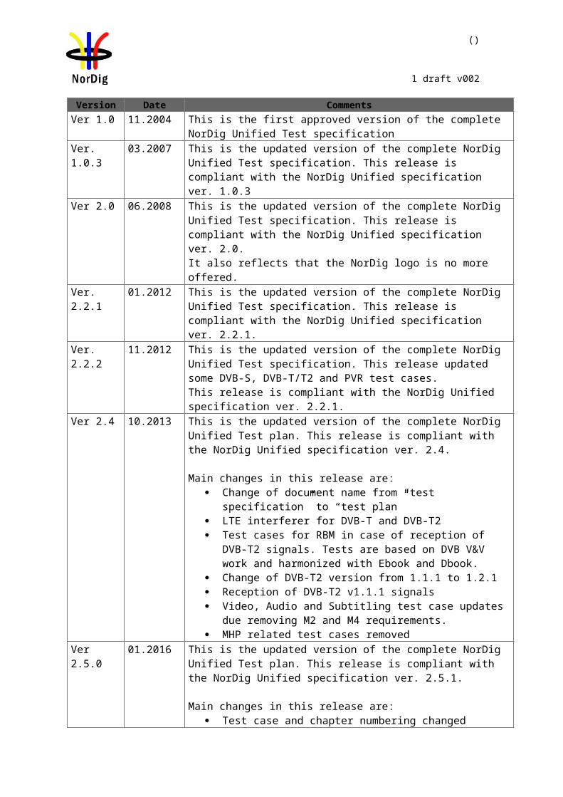
1 Document HistoryVersion Date Comments
Ver 1.0 11.2004 This is the first approved version of the complete NorDig Unified Test spe-cification
Ver. 1.0.3 03.2007 This is the updated version of the complete NorDig Unified Test specifica-tion. This release is compliant with the NorDig Unified specification ver. 1.0.3
Ver 2.0 06.2008 This is the updated version of the complete NorDig Unified Test specifica-tion. This release is compliant with the NorDig Unified specification ver. 2.0.It also reflects that the NorDig logo is no more offered.
Ver. 2.2.1 01.2012 This is the updated version of the complete NorDig Unified Test specifica-tion. This release is compliant with the NorDig Unified specification ver. 2.2.1.
Ver. 2.2.2 11.2012 This is the updated version of the complete NorDig Unified Test specifica-tion. This release updated some DVB-S, DVB-T/T2 and PVR test cases. This release is compliant with the NorDig Unified specification ver. 2.2.1.
Ver 2.4 10.2013 This is the updated version of the complete NorDig Unified Test plan. This release is compliant with the NorDig Unified specification ver. 2.4.
Main changes in this release are: Change of document name from “test specification” to “test plan” LTE interferer for DVB-T and DVB-T2 Test cases for RBM in case of reception of DVB-T2 signals. Tests
are based on DVB V&V work and harmonized with Ebook and Dbook.
Change of DVB-T2 version from 1.1.1 to 1.2.1 Reception of DVB-T2 v1.1.1 signals Video, Audio and Subtitling test case updates due removing M2 and
M4 requirements. MHP related test cases removed
Ver 2.5.0 01.2016 This is the updated version of the complete NorDig Unified Test plan. This release is compliant with the NorDig Unified specification ver. 2.5.1.
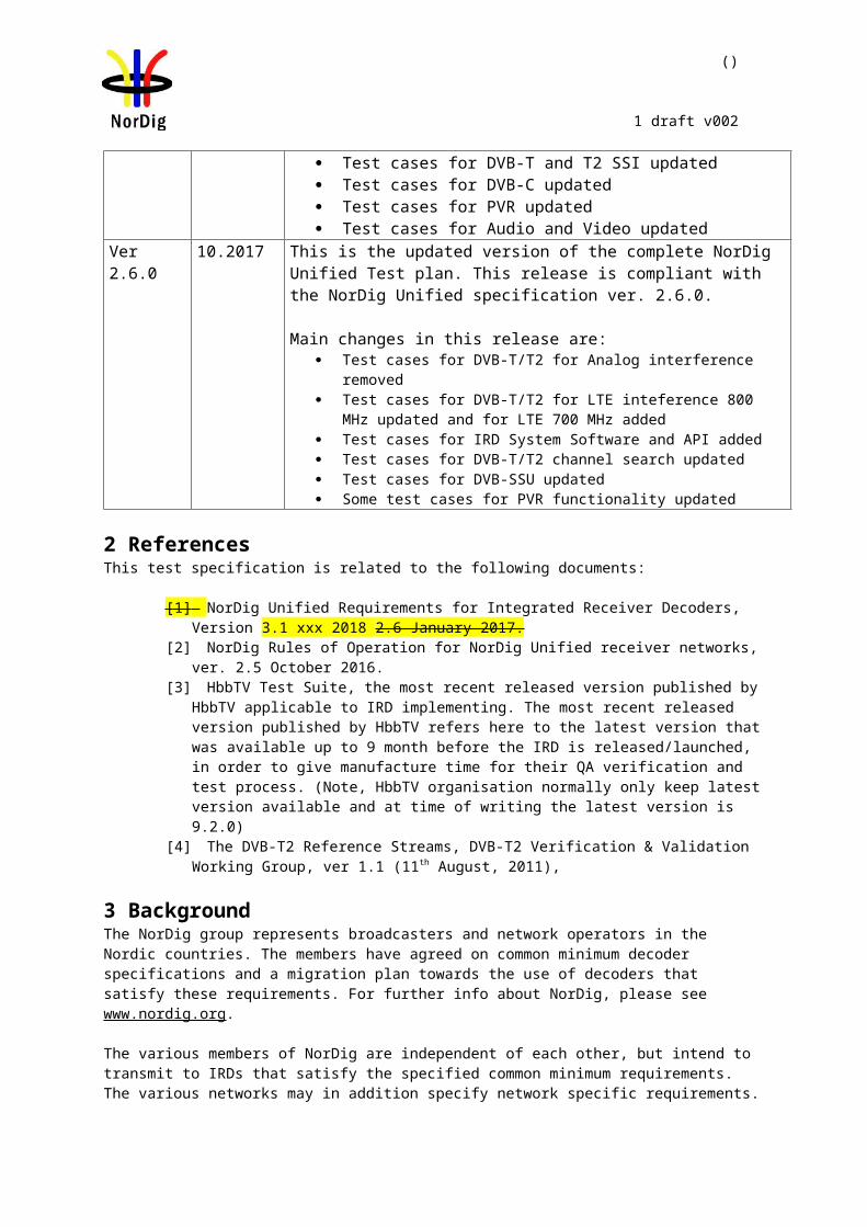
Main changes in this release are: Test case and chapter numbering changed Test cases for DVB-T and T2 SSI updated Test cases for DVB-C updated Test cases for PVR updated Test cases for Audio and Video updated
Ver 2.6.0 10.2017 This is the updated version of the complete NorDig Unified Test plan. This release is compliant with the NorDig Unified specification ver. 2.6.0.
Main changes in this release are: Test cases for DVB-T/T2 for Analog interference removed Test cases for DVB-T/T2 for LTE inteference 800 MHz updated and for
LTE 700 MHz added Test cases for IRD System Software and API added Test cases for DVB-T/T2 channel search updated Test cases for DVB-SSU updated Some test cases for PVR functionality updated
()
1 draft v002
2 ReferencesThis test specification is related to the following documents:
[1] NorDig Unified Requirements for Integrated Receiver Decoders, Version 3.1 xxx 2018 2.6 January 2017.
[2] NorDig Rules of Operation for NorDig Unified receiver networks, ver. 2.5 October 2016.[3] HbbTV Test Suite, the most recent released version published by HbbTV applicable to IRD
implementing. The most recent released version published by HbbTV refers here to the latest version that was available up to 9 month before the IRD is released/launched, in order to give manufacture time for their QA verification and test process. (Note, HbbTV organisation normally only keep latest version available and at time of writing the latest version is 9.2.0)
[4] The DVB-T2 Reference Streams, DVB-T2 Verification & Validation Working Group, ver 1.1 (11th August, 2011),
3 BackgroundThe NorDig group represents broadcasters and network operators in the Nordic countries. The members have agreed on common minimum decoder specifications and a migration plan towards the use of decoders that satisfy these requirements. For further info about NorDig, please see www.nordig.org.
The various members of NorDig are independent of each other, but intend to transmit to IRDs that satisfy the specified common minimum requirements. The various networks may in addition specify network specific requirements.
Common test specifications are established in order to ensure that decoders comply with the common minimum requirements. Additional test specifications may apply for individual networks, especially networks with access-controlled transmissions.
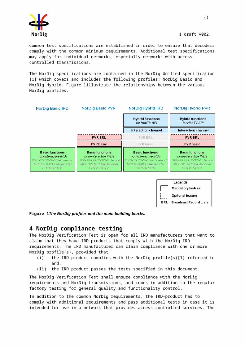
The NorDig specifications are contained in the NorDig Unified specification [1] which covers and includes the following profiles; NorDig Basic and NorDig Hybrid. Figure 1illustrate the relationships between the various NorDig profiles.
Figure 1The NorDig profiles and the main building blocks.
()
1 draft v002
4 NorDig compliance testingThe NorDig Verification Test is open for all IRD manufacturers that want to claim that they have IRD products that comply with the NorDig IRD requirements. The IRD manufacturer can claim compliance with one or more NorDig profile(s), provided that
(i) the IRD product complies with the NorDig profile(s)[1] referred to and, (ii) the IRD product passes the tests specified in this document.
The NorDig Verification Test shall ensure compliance with the NorDig requirements and NorDig transmissions, and comes in addition to the regular factory testing for general quality and functionality control.
In addition to the common NorDig requirements, the IRD-product has to comply with additional requirements and pass additional tests in case it is intended for use in a network that provides access controlled services. The additional requirements and tests will be available from the relevant Network Custodian.
The IRD Manufacturer shall furtherermore contact the relevant Network Custiodian(s) in case the IRD product shall be verified for networks with access controlled services. The relevant Network Custodian(s) will provide Network specific requirements (additional to the specified Unified NorDig Requirements) and the corresponding test specifications. Suchfurther handling has to be agreed between the IRD Manufacturer and the relevant Network Custodian (Annex A).
5 Test specifications for NorDig complianceThe NorDig Unified test plan consists of test cases and the defined test procedures in each test case are only illustrations of the test setup and the manufacturer can use different setup to run the test cases. If other, than illustrated, test setup is used the manufactures shall describe used test setup in the test report. The defined test sets may not cover all NorDig Unified Requirements [1].
If any requirement in this test specification is in contradictory with the requirement in the specification [1], the requirement in specification [1] is the valid one.
6 Testing and test report for NorDig complianceA Test Report should be made available to show compliance with the common NorDig requirements. Each individual test case should be performed; test results and conformity should be reported and signed.
In each test task a IRD profile is given. This means for which type of receiver the test task is relevant to perform. Following table specifies the abbreviations.
IRD profile Test task is dedicated for type receiverBasic IRD implements NorDig Basic or NorDig Hybrid profileHybrid IRD implements NorDig Hybrid profileIRD IRD is either IDTV or STB IDTV IRD is either IDTV, CarTV or PCTVSTB IRD is a STBFE IRD implement at least one of the following front-ends: DVB-T,DVB-T2,DVB-
C,DVB-S or DVB-S2DVB-C IRD with DVB-C tunerDVB-S IRD with DVB-S tunerDVB-S2 IRD with DVB-S2 tunerDVB-T IRD with DVB-T tunerDVB-T2 IRD with DVB-T2 tunerPVR IRD implements PVR functionality
In case that the test result indicates a non-compliance (with the specified requirement) the level of the non-compliance shall be evaluated and indicated by ticking the corresponding “box” in the conformity field. If such non-compliance can be removed by an upgrade of the IRD software, this shall be indicated by ticking the correct commentary field for the individual test. The manufacturer should describe the non-compliance and plans to correct it in the “Comments “ row.

()
1 draft v002
The Information specified for the "Test item" should be provided, see section 6.1.
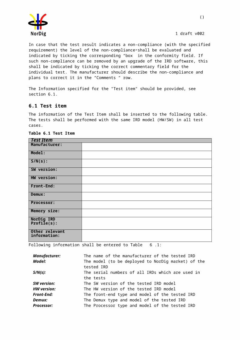
6.1 Test itemThe information of the Test Item shall be inserted to the following table. The tests shall be performed with the same IRD model (HW/SW) in all test cases.
Table 6.1 Test Item
Test ItemManufacturer:
Model:
S/N(s):
SW version:
HW version:
Front-End:
Demux:
Processor:
Memory size:
NorDig IRD Profile(s):
Other relevant information:
Following information shall be entered to Table 6.1:
Manufacturer: The name of the manufacturer of the tested IRDModel: The model (to be deployed to NorDig market) of the tested IRD S/N(s): The serial numbers of all IRDs which are used in the testsSW version: The SW version of the tested IRD modelHW version: The HW version of the tested IRD modelFront-End: The front-end type and model of the tested IRDDemux: The Demux type and model of the tested IRD Processor: The Processor type and model of the tested IRDMemory size: The memory size of the tested IRD NorDig Profile The NorDig profile of the tested IRD Other relevant information:
The other relevant information that the IRD manufacturer feels important
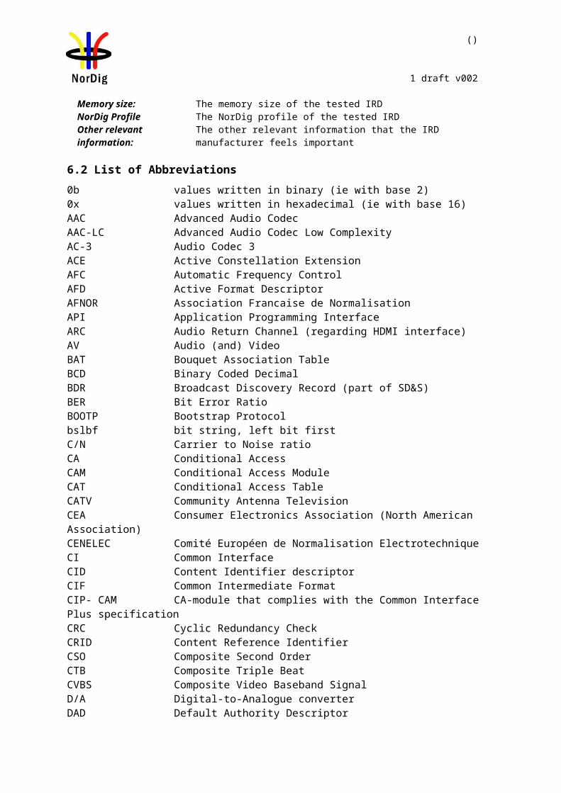
6.2 List of Abbreviations0b values written in binary (ie with base 2)0x values written in hexadecimal (ie with base 16)AAC Advanced Audio CodecAAC-LC Advanced Audio Codec Low ComplexityAC-3 Audio Codec 3ACE Active Constellation ExtensionAFC Automatic Frequency ControlAFD Active Format DescriptorAFNOR Association Francaise de NormalisationAPI Application Programming InterfaceARC Audio Return Channel (regarding HDMI interface)AV Audio (and) Video

()
1 draft v002
BAT Bouquet Association TableBCD Binary Coded DecimalBDR Broadcast Discovery Record (part of SD&S) BER Bit Error RatioBOOTP Bootstrap Protocolbslbf bit string, left bit firstC/N Carrier to Noise ratioCA Conditional Access CAM Conditional Access ModuleCAT Conditional Access TableCATV Community Antenna TelevisionCEA Consumer Electronics Association (North American Association)CENELEC Comité Européen de Normalisation ElectrotechniqueCI Common InterfaceCID Content Identifier descriptorCIF Common Intermediate FormatCIP- CAM CA-module that complies with the Common Interface Plus specificationCRC Cyclic Redundancy CheckCRID Content Reference IdentifierCSO Composite Second OrderCTB Composite Triple BeatCVBS Composite Video Baseband SignalD/A Digital-to-Analogue converterDAD Default Authority DescriptorDAVIC Digital Audio-Visual CouncildB decibeldBFS dB (relative to) Full ScaleDDS Display definition segmentDDWG Digital Display Working Group DECT Digital Enhanced Cordless TelecommunicationsDHCP Dynamic Host Configuration ProtocolDSB Double SideBandDSM-CC Digital Storage Media Command and ControlDTS Digital Theater System (audio codec)DVB Digital Video BroadcastingDVB-C Digital Video Broadcasting – CableDVB-CAM CA-module that complies with the DVB Common Interface specificationDVB-data Digital Video Broadcasting – Data BroadcastingDVB-S Digital Video Broadcasting – SatelliteDVB-T DVB-TerrestrialE-AC-3 Enhanced Audio Codec 3E-EDID Enhanced Extended Display Identification Data (regarding HDMI interface)EBU European Broadcasting UnionECCA European Cable Communications AssociationECL EuroCableLabs, technical cell of ECCAEICTA European Information & Communications Technology Industry AssociationEIT Event Information TableEITp/f Event Information Table, present/following tablesEITsch Event Information Table, schedule tablesEITp Event Information Table, present table/section of EITp/fEITf Event Information Table, following table/section of EITp/fEPT Effective Protection TargetEPG Electronic Program Guide (based on API)
()
1 draft v002
ESG Event Schedule Guide (without any API)FEF Future Extension FrameFFT Fast Fourier TransformGAP Generic Access ProtocolGOP Group Of PicturesGPRS General Packet Radio SystemGS Generic StreamGSM Group Special MobileHbbTV Hybrid Broadcast Broadband TVHDCP High-bandwidth Digital Content ProtectionHDMI High-Definition Multimedia InterfaceHDMI ARC HDMI Audio Return ChannelHDTV High Definition TelevisionHE-AAC High Efficiency Advanced Audio CodecHTTP HyperText Transfer ProtocoliDTV integrated Digital TV (IRD with display)IEC International Electrotechnical CommissionIEEE Institute for Electrical and Electronic EngineersIEFT Internet Engineering Task ForceIGMP Internet Group Management ProtocolINA Interactive Network AdapterIP Internet ProtocolIRD Integrated Receiver Decoder IMI Instant Metadata Identifier ISO International Organisation for Standardisation JTC Joint Technical CommitteeLCD Logical Channel DescriptorLCN Logical Channel NumberLU Loudness UnitsLUFS Loudness Units (relative to) Full ScaleL-PCM Linear Pulse Code ModulationMAC Medium Access ControlMPEG Moving Pictures Expert GroupMPTS Multi Programme Transport StreamMTU Maximum Transfer UnitNEM Network Element ManagementNIC Network Interface CardNIT Network Information TableNT Network Termination in generalNVOD Near Video On DemandOSD On Screen DisplayPAL Phase Alternating LinePAPR Peak-toAverage-Power RatioPAT Program Association TablePCM Pulse Code ModulationPLP Physical Layer PipePID Packet IdentifierPMT Program Map TablePSI Program Specific Information PSTN Public Switched Telephone NetworkPCR Programme Clock ReferancePVR Personal Video Recorder, (same as PDR, Personal Digital Recorder, or DVR)
()
1 draft v002
QAM Quadrature Amplitude ModulationQCIF Quarter Common Intermediate FormatQEF Quasi Error FreeQoS Quality of ServiceQPSK Quaternary Phase Shift KeyingRF Radio FrequencyRFC Request For CommentsRMS Root Mean SquareRoO Rules of Operationrpchof remainder polynomial coefficients, highest order firstRS Reed-SolomonRST Running Status Table RTCP Real-Time Transport Control ProtocolRTP Real-Time Transport ProtocolRTSP Real Time Streaming ProtocolS/PDIF Sony Philips Digital Interface (for digital audio)SAP Session Announcement ProtocolSBR Spectral Band Replication (regarding HE-AAC audio)SCART Syndicat des Constructeurs d'Appareils Radiorécepteurs et Téléviseurs
(video/audio interface)SD&S Service Discovery and SelectionSDT Service Description TableSDTV Standard Definition TelevisionSFN Single Frequency NetworkSI Service Information SMATV Satellite Master Antenna Television SNTP Simple Network Time ProtocolSPTS Single Programme Transport Stream ST Stuffing TableSTB Set-top box (IRD without display)SW Software TCP Transmission Control ProtocolTDT Time and Date Table TFS Time Frequency SlicingTFTP Tunnelling File Transfer ProtocolTOT Time Offset TableTPS Transmission Parameter SignallingTRS Tip Ring SleeveTR Tone ReservationTS Transport StreamTV TelevisionTVA TV AnytimeUHF Ultra-High Frequencyuimsbf unsigned integer most significant bit firstUTC Universal Time, Co-ordinatedVCR Video Cassette Recorder VHF Very-High FrequencyVHS Video Home System VoIP Voice over IPVPN Virtual Private NetworkVSB Vestigial SideBandxDSL x Digital Subscriber LineXML Extensible Markup Language
()
1 draft v002
Part II - Test Cases
()
1 draft v002
1 Introduction - Test CasesThe NorDig plan specifications Test Cases are grouped into a set of test tasks, covering related tests:
Task 1: Satellite tuner and demodulatorTask 2: Cable Tuner and DemodulatorTask 3: Terrestrial Tuner and DemodulatorTask 4: IP-Based Front-endTask 5: MPEG2 demultiplexerTask 6: VideoTask 7: AudioTask 8: Teletext and subtitlingTask 9: Interfaces and Signal LevelsTask 10: Interfaces for Conditional AccessError: Reference source not foundError: Reference source not foundTask 13: Service InformationTask 15: PVR FunctionalityTask 16: IRD System Software and APITask 17: User Preferences
Each of the main tasks defined above include a number of sub-tasks.
Table 1 maps the NorDig requirements [1] into the corresponding test tasks and shows the relevance per sub-task for the various NorDig profiles (“shall” indicates a mandatory requirement and a mandatory test).
()
1 draft v002
Table 1A. Task A: Front endsNorDig Test Task NorDig IRD ProfileTest Task STB IDTV Basic Hybrid PVR DVB-S DVB-S2 DVB-C DVB-T DVB-T22.1 Task 1: Satellite tuner and demodulator - - - - - - - - - -Task 1:1 General Shall Shall Shall Shall Shall Shall Shall - - -Task 1:2 General Shall Shall Shall Shall Shall Shall Shall - - -Task 1:3 Quality reception detector Shall Shall Shall Shall Shall Shall Shall - - -Task 1:4 Symbol and FEC-rate (DVB-S2) Shall Shall Shall Shall Shall Shall Shall - - -Task 1:5 Input Frequency Range/Tuning range Shall Shall Shall Shall Shall Shall Shall - - -Task 1:6 Tuning/ Scanning Procedures (with NIT) Shall Shall Shall Shall Shall Shall Shall - - -Task 1:7 Tuning/ Scanning Procedures (without NIT) Shall Shall Shall Shall Shall Shall Shall - - -Task 1:8 Control signals Shall Shall Shall Shall Shall Shall Shall - - -Task 1:9 Demodulation (DVB-S2) Shall Shall Shall Shall Shall Shall Shall - - -Task 1:10 RF Input Connector and Output Connector (option) Shall Shall Shall Shall Shall Shall Shall - - -
Task 1:11 Input Signal Level Shall Shall Shall Shall Shall Shall Shall - - -Task 1:12 Power Supply and Control Signal (to RF unit) Shall Shall Shall Shall Shall Shall Shall - - -Task 1:13 Power Supply and Control Signal (to single-channel RF unit) Shall Shall Shall Shall Shall Shall Shall - - -
Task 1:14 Performance: Digital interference Shall Shall Shall Shall Shall Shall Shall - - -2.2 Task 2: Cable Tuner and Demodulator - - - - - - - - - -Task 2:1 General Shall Shall Shall Shall Shall - - Shall - -Task 2:2 General Shall Shall Shall Shall Shall - - Shall - -Task 2:3 Quality reception detector Shall Shall Shall Shall Shall - - Shall - -Task 2:4 RF Characteristics: Input frequency range and input level, Digital channels Shall Shall Shall Shall Shall - - Shall - -
Task 2:5 RF Characteristics: Symbol rate and modula-tion Shall Shall Shall Shall Shall - - Shall - -
Task 2:6 RF Characteristics: Input impedance Shall Shall Shall Shall Shall - - Shall - -Task 2:7 RF bypass Shall Shall Shall Shall Shall - - Shall - -Task 2:8 Tuning/Scanning procedure (Automatic scan based on NIT) Shall Shall Shall Shall Shall - - Shall - -
Task 2:9 Tuning/Scanning procedure (Manual scan) Shall Shall Shall Shall Shall - - Shall - -Task 2:10 Tuning/Scanning procedure (Original_net-work_id, transport_stream_id and service_id triplet support)
Shall Shall Shall Shall Shall - - Shall - -
Task 2:11 Tuning/Scanning procedure - Network default values Shall Shall Shall Shall Shall - - Shall - -
Task 2:12 Tuning/Scanning procedure - Factory default values Shall Shall Shall Shall Shall - - Shall - -
Task 2:13 Total input power Shall Shall Shall Shall Shall - - Shall - -Task 2:14 RF Performance - C/N for Reference BER Shall Shall Shall Shall Shall - - Shall - -Task 2:15 RF Performace - C/N with echo Shall Shall Shall Shall Shall - - Shall - -Task 2:16 Performance Data: Noise figure Shall Shall Shall Shall Shall - - Shall - -Task 2:17 RF Performance - Image Channel Shall Shall Shall Shall Shall - - Shall - -Task 2:18 RF Performance - Digital Adjacent Channel Shall Shall Shall Shall Shall - - Shall - -Task 2:19 RF Performance - Analog Adjacent Channel Shall Shall Shall Shall Shall - - Shall - -Task 2:20 LO leakage Shall Shall Shall Shall Shall - - Shall - -Task 2:21 Spurious emission Shall Shall Shall Shall Shall - - Shall - -Task 2:22 Radiation Shall Shall Shall Shall Shall - - Shall - -2.3 Task 3: Terrestrial Tuner and Demodulator - - - - - - - - - -Task 3:1 General Shall Shall Shall Shall Shall - - - Shall ShallTask 3:2 General Shall Shall Shall Shall Shall - - - Shall ShallTask 3:3 Quality reception detector Shall Shall Shall Shall Shall - - - Shall ShallTask 3:4 Frequencies: Center frequencies Shall Shall Shall Shall Shall - - - Shall ShallTask 3:5 Frequencies: Frequency offset Shall Shall Shall Shall Shall - - - Shall ShallTask 3:6 Frequencies: Signal bandwidths Shall Shall Shall Shall Shall - - - Shall ShallTask 3:7 Modes Shall Shall Shall Shall Shall - - - Shall ShallTask 3:8 Tuning/Scanning Procedure: General Shall Shall Shall Shall Shall - - - Shall ShallTask 3:9 Tuning/Scanning Procedures: Basic status check Shall Shall Shall Shall Shall - - - Shall Shall
Task 3:10 Tuning/Scanning Procedures: Automatic channel search for the same service bouquet Shall Shall Shall Shall Shall - - - Shall Shall
Task 3:11 Tuning/Scanning: Automatic channel search for different service bouquets Shall Shall Shall Shall Shall - - - Shall Shall
Task 3:12 Tuning/Scanning Procedures: Manual Chan-nel Search Shall Shall Shall Shall Shall - - - Shall Shall
Task 3:13 Verification of Signal Strength Indicator (SSI) Shall Shall Shall Shall Shall - - - Shall ShallTask 3:14 Verification of Signal Quality Indicator (SQI) Shall Shall Shall Shall Shall - - - Shall ShallTask 3:15 Changes In Modulation Parameters Shall Shall Shall Shall Shall - - - Shall ShallTask 3:16 RF input connector Shall Shall Shall Shall Shall - - - Shall ShallTask 3:17 RF output connector Shall Shall Shall Shall Shall - - - Shall ShallTask 3:18 Performance: BER vs C/N verification Shall Shall Shall Shall Shall - - - Shall ShallTask 3:19 Performance: C/N performance on Gaussian channel Shall Shall Shall Shall Shall - - - Shall Shall
Task 3:20 Performance: C/N performance on 0dB echo channel Shall Shall Shall Shall Shall - - - Shall Shall
Task 3:21 Performance: Minimum receiver signal input levels on Gaussian channel Shall Shall Shall Shall Shall - - - Shall Shall
Task 3:22 Performance: Minimum IRD Signal Input Lev-els on 0dB echo channel Shall Shall Shall Shall Shall - - - Shall Shall
Task 3:23 Performance: Noise figure on Gaussian channel Shall Shall Shall Shall Shall - - - Shall Shall
Task 3:24 Performance: Maximum Receiver Signal In-put Levels Shall Shall Shall Shall Shall - - - Shall Shall
Task 3:25 Performance: Immunity to "digital" signals in Other Channels Shall Shall Shall Shall Shall - - - Shall Shall
Task 3:26 Performance: Immunity to “LTE 700 MHz” signals in Other Channels Shall Shall Shall Shall Shall - - - Shall Shall
Task 3:27 Performance: Immunity to “LTE 800 MHz” signals in Other Channels Shall Shall Shall Shall Shall - - - Shall Shall
()
1 draft v002
NorDig Test Task NorDig IRD ProfileTest Task STB IDTV Basic Hybrid PVR DVB-S DVB-S2 DVB-C DVB-T DVB-T2Task 3:28 Performance: Performance in Time-Varying Channels Shall Shall Shall Shall Shall - - - Shall Shall
Task 3:29 Performance: Synchronisation for varying echo power levels in SFN Shall Shall Shall Shall Shall - - - Shall Shall
Task 3:30 Performance: C/(N+I) Performance in SFN for more than one echo Shall Shall Shall Shall Shall - - - Shall Shall
Task 3:31 Performance: C/(N+I) Performance in SFN in-side the guard interval Shall Shall Shall Shall Shall - - - Shall Shall
Task 3:32 Performance: C/(N+I) Performance in SFN outside the guard interval Shall Shall Shall Shall Shall - - - Shall Shall
Task 3:33 DVB-T2: Frequencies: Center frequencies Shall Shall Shall Shall Shall - - - Shall ShallTask 3:34 DVB-T2: Frequencies: Frequency offset Shall Shall Shall Shall Shall - - - Shall ShallTask 3:35 DVB-T2: Frequencies: Signal bandwidths Shall Shall Shall Shall Shall - - - Shall ShallTask 3:36 DVB-T2: Modes Shall Shall Shall Shall Shall - - - Shall ShallTask 3:37 DVB-T2: MISO Shall Shall Shall Shall Shall - - - Shall ShallTask 3:38 DVB-T2: Input Mode B (multiple PLPs) Shall Shall Shall Shall Shall - - - Shall ShallTask 3:39 DVB-T2: Input Mode B (multiple PLPs and common PLP) Shall Shall Shall Shall Shall - - - Shall Shall
Task 3:40 DVB-T2: Input Mode B (RBM for TDI) Shall Shall Shall Shall Shall - - - Shall ShallTask 3:41 DVB-T2: Input Mode B (RBM for DJB) Shall Shall Shall Shall Shall - - - Shall ShallTask 3:42 DVB-T2: Input Mode B (RBM when FEF present) Shall Shall Shall Shall Shall - - - Shall Shall
Task 3:43 DVB-T2: Normal mode (NM) Shall Shall Shall Shall Shall - - - Shall ShallTask 3:44 DVB-T2: Input Mode A (zero power FEF present) Shall Shall Shall Shall Shall - - - Shall Shall
Task 3:45 DVB-T2: Input Mode A (RBM when FEF present) Shall Shall Shall Shall Shall - - - Shall Shall
Task 3:46 DVB-T2: Auxialiary streams Shall Shall Shall Shall Shall - - - Shall ShallTask 3:47 DVB-T2: Reception of version 1.1.1 Shall Shall Shall Shall Shall - - - Shall ShallTask 3:48 DVB-T2: Tuning/Scanning Procedures: Auto-matic channel search for the same service bouquet Shall Shall Shall Shall Shall - - - Shall Shall
Task 3:49 DVB-T2: Tuning/Scanning Procedures: Basic status check Shall Shall Shall Shall Shall - - - Shall Shall
Task 3:50 DVB-T2: Verification of Signal Strength Indi-cator (SSI) Shall Shall Shall Shall Shall - - - Shall Shall
Task 3:51 DVB-T2: Verification of Signal Quality Indica-tor (SQI) Shall Shall Shall Shall Shall - - - Shall Shall
Task 3:52 DVB-T2: Changes In Modulation Parameters Shall Shall Shall Shall Shall - - - Shall ShallTask 3:53 DVB-T2: Time interleaving Shall Shall Shall Shall Shall - - - Shall ShallTask 3:54 DVB-T2: Input/Output Data Formats Shall Shall Shall Shall Shall - - - Shall ShallTask 3:55 DVB-T2: Performance: BER vs C/N verifica-tion Shall Shall Shall Shall Shall - - - Shall Shall
Task 3:56 DVB-T2: Performance: C/N performance on Gaussian channel Shall Shall Shall Shall Shall - - - Shall Shall
Task 3:57 DVB-T2: Performance: C/N performance on 0dB echo channel Shall Shall Shall Shall Shall - - - Shall Shall
Task 3:58 DVB-T2: Performance: Minimum receiver sig-nal input levels on Gaussian channel Shall Shall Shall Shall Shall - - - Shall Shall
Task 3:59 DVB-T2: Performance: Minimum IRD Signal Input Levels on 0dB echo channel Shall Shall Shall Shall Shall - - - Shall Shall
Task 3:60 DVB-T2: Performance: Receiver noise figure on Gaussian channel Shall Shall Shall Shall Shall - - - Shall Shall
Task 3:61 DVB-T2: Performance: Maximum Receiver Signal Input Levels Shall Shall Shall Shall Shall - - - Shall Shall
Task 3:62 DVB-T2: Performance: Immunity to "digital" signals in Other Channels Shall Shall Shall Shall Shall - - - Shall Shall
Task 3:63 DVB-T2: Performance: Immunity to “LTE 700 MHz” signals in Other Channels Shall Shall Shall Shall Shall - - - Shall Shall
Task 3:64 DVB-T2: Performance: Immunity to “LTE 800 MHz” signals in Other Channels Shall Shall Shall Shall Shall - - - Shall Shall
Task 3:65 DVB-T2: Performance: Performance in Time-Varying Channels Shall Shall Shall Shall Shall - - - Shall Shall
Task 3:66 DVB-T2: Performance: Synchronisation for varying echo power levels in SFN Shall Shall Shall Shall Shall - - - Shall Shall
Task 3:67 DVB-T2: Performance: C/(N+I) Performance in SFN for more than one echo Shall Shall Shall Shall Shall - - - Shall Shall
Task 3:68 DVB-T2: Performance: C/(N+I) Performance in SFN inside the guard interval Shall Shall Shall Shall Shall - - - Shall Shall
Task 3:69 DVB-T2: Performance: C/(N+I) Performance in SFN outside the guard interval Shall Shall Shall Shall Shall - - - Shall Shall
2.4 Task 4: IP-Based Front-end - - - - - - - - - -
Table 1B. Hardware, Audio/Video and Subtitling IssuesNorDig Test Task NorDig IRD ProfileTest Task STB IDTV Basic Hybrid PVR DVB-S DVB-
S2DVB-C DVB-
TDVB-T2
2.5 Task 5: MPEG2 demultiplexer - - - - - - - - - -Task 5:1 SI utilization Shall Shall Shall Shall Shall Shall Shall Shall Shall ShallTask 5:2 CA descriptor interpretation Shall Shall Shall Shall Shall Shall Shall Shall Shall ShallTask 5:3 Maximum transport stream data rate Shall Shall Shall Shall Shall Shall Shall Shall Shall ShallTask 5:4 Number of elementary streams Shall Shall Shall Shall Shall Shall Shall Shall Shall ShallTask 5:5 Section filtering Shall Shall Shall Shall Shall Shall Shall Shall Shall ShallTask 5:6 Variable Bitrate Elementary Streams Shall Shall Shall Shall Shall Shall Shall Shall Shall ShallTask 5:7 Mixture of SD and HD services Shall Shall Shall Shall Shall Shall Shall Shall Shall ShallTask 5:8 Descrambler Performance Shall Shall Shall Shall Shall Shall Shall Shall Shall ShallTask 5:9 System clock recovery Shall Shall Shall Shall Shall Shall Shall Shall Shall Shall2.6 Task 6: Video - - - - - - - - - -Task 6:1 Video Decoder - General Shall Shall Shall Shall Shall Shall Shall Shall Shall ShallTask 6:2 Video Decoder - Resolutions and Frame rates Shall Shall Shall Shall Shall Shall Shall Shall Shall Shall
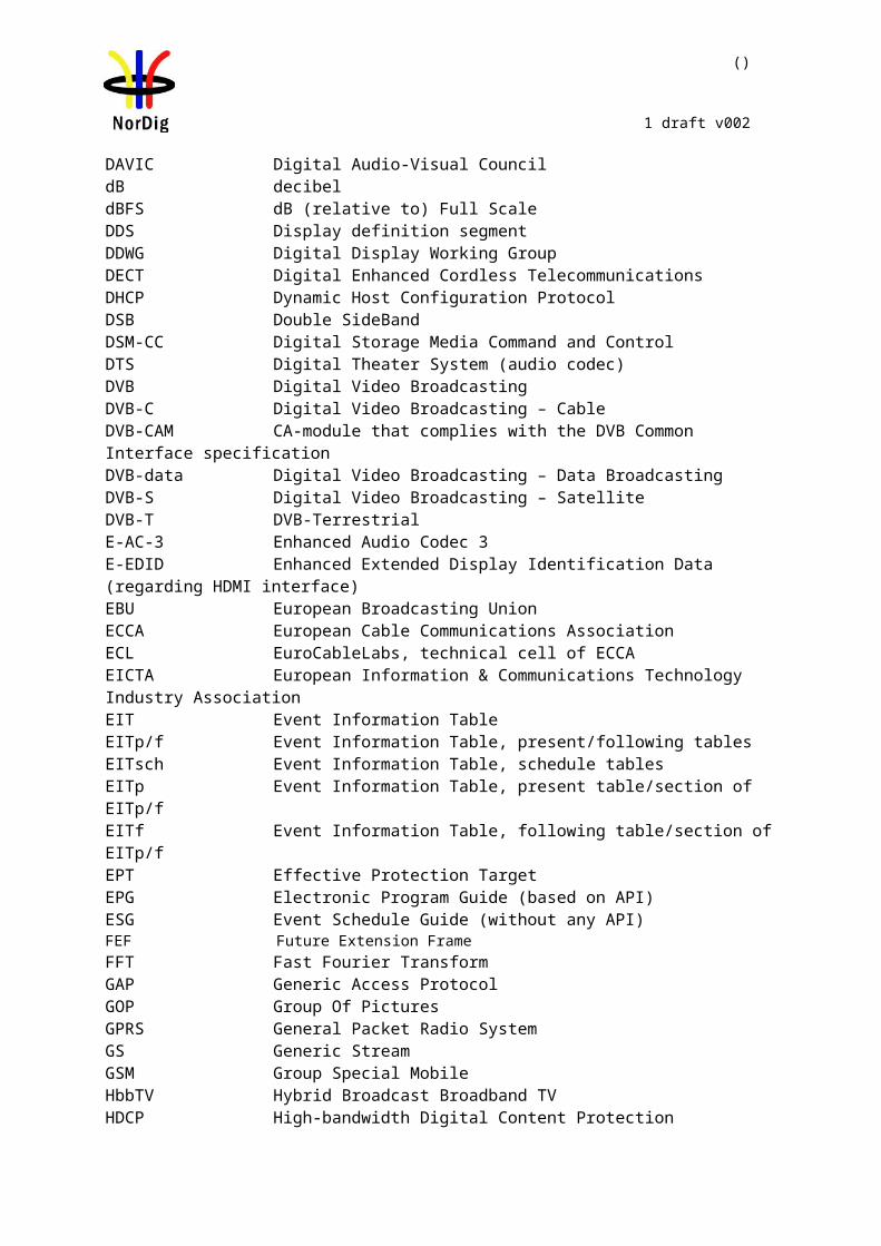
()
1 draft v002
NorDig Test Task NorDig IRD ProfileTest Task STB IDTV Basic Hybrid PVR DVB-S DVB-
S2DVB-C DVB-
TDVB-T2
Task 6:3 Up-sampling/Up-conversion Shall Shall Shall Shall Shall Shall Shall Shall Shall ShallTask 6:4 Video Decoder - Colorimetry Shall Shall Shall Shall Shall Shall Shall Shall Shall ShallTask 6:5 Video Decoder - Dynamic changes in video stream
Shall Shall Shall Shall Shall Shall Shall Shall Shall Shall
Task 6:6 Video Decoder - AVC still picture Shall Shall Shall Shall Shall Shall Shall Shall Shall ShallTask 6:7 Minimum video bandwidth Shall Shall Shall Shall Shall Shall Shall Shall Shall ShallTask 6:8 Frame cropping Shall Shall Shall Shall Shall Shall Shall Shall Shall ShallTask 6:9 Overscan Shall Shall Shall Shall Shall Shall Shall Shall Shall ShallTask 6:10 High Definition Video Output and Display Shall Shall Shall Shall Shall Shall Shall Shall Shall ShallTask 6:11 Down-conversion of High Definition Video for Standard Definition output
Shall Shall Shall Shall Shall Shall Shall Shall Shall Shall
Task 6:12 16:9 displayed on 4:3 monitors Shall Shall Shall Shall Shall Shall Shall Shall Shall ShallTask 6:13 Displaying 4:3 Material on 16:9 Monitors Shall Shall Shall Shall Shall Shall Shall Shall Shall ShallTask 6:14 Rescaling for HbbTV application Shall Shall - Shall - Shall Shall Shall Shall Shall2.7 Task 7: Audio - - - - - - - - - -Task 7:1 Audio User Preference Settings Shall Shall Shall Shall Shall Shall Shall Shall Shall ShallTask 7:2 MPEG-1 Layer II: Requirements Shall Shall Shall Shall Shall Shall Shall Shall Shall ShallTask 7:3 MPEG-1 Layer II: Analogue audio output Shall Shall Shall Shall Shall Shall Shall Shall Shall ShallTask 7:4 MPEG-1 Layer II: HDMI output interface Shall Shall Shall Shall Shall Shall Shall Shall Shall ShallTask 7:5 MPEG-1 Layer II: S/PDIF output interface Shall Shall Shall Shall Shall Shall Shall Shall Shall ShallTask 7:6 AC-3: Requirements Shall Shall Shall Shall Shall Shall Shall Shall Shall ShallTask 7:7 AC-3: Analogue audio output Shall Shall Shall Shall Shall Shall Shall Shall Shall ShallTask 7:8 AC-3: HDMI output and HDMI ARC interface Shall Shall Shall Shall Shall Shall Shall Shall Shall ShallTask 7:9 AC-3: S/PDIF output interface Shall Shall Shall Shall Shall Shall Shall Shall Shall ShallTask 7:10 AC-3: Metadata Shall Shall Shall Shall Shall Shall Shall Shall Shall ShallTask 7:11 E-AC-3: Requirements Shall Shall Shall Shall Shall Shall Shall Shall Shall ShallTask 7:12 E-AC-3: Analogue audio output Shall Shall Shall Shall Shall Shall Shall Shall Shall ShallTask 7:13 E-AC-3: HDMI output and HDMI ARC inter-face
Shall Shall Shall Shall Shall Shall Shall Shall Shall Shall
Task 7:14 E-AC-3: S/PDIF output interface Shall Shall Shall Shall Shall Shall Shall Shall Shall ShallTask 7:15 E-AC3: Metadata Shall Shall Shall Shall Shall Shall Shall Shall Shall ShallTask 7:16 HE AAC: Requirements Shall Shall Shall Shall Shall Shall Shall Shall Shall ShallTask 7:17 HE AAC: Analogue audio output Shall Shall Shall Shall Shall Shall Shall Shall Shall ShallTask 7:18 HE AAC: HDMI output and HDMI ARC inter-face
Shall Shall Shall Shall Shall Shall Shall Shall Shall Shall
Task 7:19 HE AAC: S/PDIF output interface Shall Shall Shall Shall Shall Shall Shall Shall Shall ShallTask 7:20 HE AAC: Metadata Shall Shall Shall Shall Shall Shall Shall Shall Shall ShallTask 7:21 Audio prioritizing - Audio language support Shall Shall Shall Shall Shall Shall Shall Shall Shall ShallTask 7:22 Audio Prioritising - audio format and stream type
Shall Shall Shall Shall Shall Shall Shall Shall Shall Shall
Task 7:23 Audio Prioritising - audio type Shall Shall Shall Shall Shall Shall Shall Shall Shall ShallTask 7:24 Audio Prioritising - audio format signaling missing
Shall Shall Shall Shall Shall Shall Shall Shall Shall Shall
Task 7:25 Audio video synchronization Shall Shall Shall Shall Shall Shall Shall Shall Shall ShallTask 7:26 Adjustement of Video/audio-delay Shall Shall Shall Shall Shall Shall Shall Shall Shall ShallTask 7:27 Audio handling when changing service or audio format
Shall Shall Shall Shall Shall Shall Shall Shall Shall Shall
Task 7:28 Dynamic changes in audio components Shall Shall Shall Shall Shall Shall Shall Shall Shall ShallTask 7:29 Audio descriptors Shall Shall Shall Shall Shall Shall Shall Shall Shall ShallTask 7:30 Clean audio Shall Shall Shall Shall Shall Shall Shall Shall Shall ShallTask 7:31 Supplementary audio Shall Shall Shall Shall Shall Shall Shall Shall Shall ShallTask 7:32 IRD Internal Reference Level Shall Shall Shall Shall Shall Shall Shall Shall Shall ShallTask 7:33 Loudness levels Shall Shall Shall Shall Shall Shall Shall Shall Shall Shall2.8 Task 8: Teletext and subtitling - - - - - - - - - -Task 8:1 Subtitling - user preferences Shall Shall Shall Shall Shall Shall Shall Shall Shall ShallTask 8:2 Subtitling - Only display subtitling if match language in user preferences
Shall Shall Shall Shall Shall Shall Shall Shall Shall Shall
Task 8:3 Subtitling - Temporary changes to subtitling settings
Shall Shall Shall Shall Shall Shall Shall Shall Shall Shall
Task 8:4 Subtitling - Subtitling mode (Normal and Hard of hearing subtitling)
Shall Shall Shall Shall Shall Shall Shall Shall Shall Shall
Task 8:5 Subtitling - DVB Subtitling and subtitling pri-ority (DVB/EBU)
Shall Shall Shall Shall Shall Shall Shall Shall Shall Shall
Task 8:6 Teletext - Simultaneous EBU Teletext and HbbTV Digital Teletext
Shall Shall Shall Shall Shall Shall Shall Shall Shall Shall
Task 8:7 Subtitling - coexistent with HbbTV applica-tions
Shall Shall - Shall - Shall Shall Shall Shall Shall
Task 8:8 Teletext - EBU Teletext level 1.5 Shall Shall Shall Shall Shall Shall Shall Shall Shall ShallTask 8:9 Teletext - decoding method(VBI) Shall Shall Shall Shall Shall Shall Shall Shall Shall ShallTask 8:10 Teletext decoding method(OSD) Shall Shall Shall Shall Shall Shall Shall Shall Shall ShallTask 8:11 Teletext - teletext pages Shall Shall Shall Shall Shall Shall Shall Shall Shall ShallTask 8:12 Teletext - teletext pages - cache Shall Shall Shall Shall Shall Shall Shall Shall Shall ShallTask 8:13 Subtitling - teletext subtitling Shall Shall Shall Shall Shall Shall Shall Shall Shall ShallTask 8:14 Subtitling - DVB Subtitling Shall Shall Shall Shall Shall Shall Shall Shall Shall Shall2.9 Task 9: Interfaces and Signal Levels - - - - - - - - - -Task 9:1 Two-way Interface Shall Shall - Shall - Shall Shall Shall Shall ShallTask 9:2 SCART Interface Shall Shall Shall Shall Shall Shall Shall Shall Shall ShallTask 9:3 HDMI interface - HD Ready Shall Shall Shall Shall Shall Shall Shall Shall Shall ShallTask 9:4 HDMI interface - EDID information Shall - Shall Shall Shall Shall Shall Shall Shall ShallTask 9:5 HDMI interface - Original format Shall - Shall Shall Shall Shall Shall Shall Shall ShallTask 9:6 HDMI - Manual setting for resolution Shall Shall Shall Shall Shall Shall Shall Shall Shall ShallTask 9:7 HDMI - Signal protection Shall Shall Shall Shall Shall Shall Shall Shall Shall ShallTask 9:8 Analogue video interface(Option) Shall Shall Shall Shall Shall Shall Shall Shall Shall ShallTask 9:9 Remote Control Function Keys Shall Shall Shall Shall Shall Shall Shall Shall Shall ShallTask 9:10 Remote Control Function Keys for PVR Shall Shall Shall Shall Shall Shall Shall Shall Shall ShallTask 9:11 Remote Control Key event mapping for NorDig Hybrid
Shall Shall - Shall Shall Shall Shall Shall Shall Shall
2.10 Task 10: Interfaces for Conditional Access - - - - - - - - - -Task 10:1 Use of Common Interface Shall Shall Shall Shall Shall Shall Shall Shall Shall Shall
()
1 draft v002
NorDig Test Task NorDig IRD ProfileTest Task STB IDTV Basic Hybrid PVR DVB-S DVB-
S2DVB-C DVB-
TDVB-T2
Task 10:2 Smart Card Interface Shall Shall Shall Shall Shall Shall Shall Shall Shall Shall2.11 Task 11: The System Software Update - - - - - - - - - -Task 11:1 IRD System software update using DVB SSU simple profile
Shall Shall Shall Shall Shall Shall Shall Shall Shall Shall
Task 11:2 IRD System software update using DVB SSU enhanced profile - scheduling
Shall Shall Shall Shall Shall Shall Shall Shall Shall Shall
Task 11:3 SSU end user functionality Shall Shall Shall Shall Shall Shall Shall Shall Shall ShallTask 11:4 Common interface plus (CI+) CAM module system software update
- Shall Shall Shall Shall Shall Shall Shall Shall Shall
2.12 Task 12: Performance - - - - - - - - - -Task 12:1 Video performance Shall Shall Shall Shall Shall Shall Shall Shall Shall ShallTask 12:2 Audio performance Shall Shall Shall Shall Shall Shall Shall Shall Shall ShallTask 12:3 Zapping time Shall Shall Shall Shall Shall Shall Shall Shall Shall Shall
Table 1C. System Software issuesNorDig Test Task NorDig IRD ProfileTest Task STB IDTV Basic Hy-
bridPVR DVB-S DVB-
S2DVB-
CDVB-T DVB-
T22.13 Task 13: Service Information - - - - - - - - - -Task 13:1 SI: General Shall Shall Shall Shall Shall Shall Shall Shall Shall ShallTask 13:2 SI: General - Undefined data structures Shall Shall Shall Shall Shall Shall Shall Shall Shall ShallTask 13:3 SI: General - 'Actual' and 'Other' tables Shall Shall Shall Shall Shall Shall Shall Shall Shall ShallTask 13:4 SI: SI data available through an API Shall Shall - Shall - Shall Shall Shall Shall ShallTask 13:5 SI: Text strings and field size of the SI descriptor
Shall Shall Shall Shall Shall Shall Shall Shall Shall Shall
Task 13:6 NIT_actual - frequency_list_descriptor Shall Shall Shall Shall Shall - - - Shall ShallTask 13:7 NIT_actual - Missing terrestrial_system_delivery_descriptor
Shall Shall Shall Shall Shall - - - Shall Shall
Task 13:8 NIT_actual - Missing T2_delivery_sys-tem_descriptor
Shall Shall Shall Shall Shall - - - Shall Shall
Task 13:9 SDT_actual service_descriptor and CA_identifier_descriptor
Shall Shall Shall Shall Shall Shall Shall Shall Shall Shall
Task 13:10 Quasi static update of SDT_actual Shall Shall Shall Shall Shall Shall Shall Shall Shall ShallTask 13:11 Quasi-static update of SDT_actual - linkage to NorDig simulcast replacement service
Shall Shall Shall Shall Shall Shall Shall Shall Shall Shall
Task 13:12 Quasi-static update of NIT_actual - Linkage to an information service about the net-work
Shall Shall Shall Shall Shall Shall Shall Shall Shall Shall
Task 13:13 Quasi-static update of NIT_actual - Linkage to EPG service
Shall Shall Shall Shall Shall Shall Shall Shall Shall Shall
Task 13:14 Quasi-static update of NIT_actual - Linkage to TS that carriers EIT sch information for all services
Shall Shall Shall Shall Shall Shall Shall Shall Shall Shall
Task 13:15 Quasi-static update of NIT_actual - Linkage to System Software Download service
Shall Shall Shall Shall Shall Shall Shall Shall Shall Shall
Task 13:16 Dynamic update of SDT_actual running status and linkage to a service replacement service
Shall Shall Shall Shall Shall Shall Shall Shall Shall Shall
Task 13:17 Dynamic update of EIT actual/other p/f Shall Shall Shall Shall Shall Shall Shall Shall Shall ShallTask 13:18 Dynamic update of EIT_actual p/f CA_identifier_descriptor
Shall Shall Shall Shall Shall - - - Shall Shall
Task 13:19 Dynamic update of EIT actual/other p/f short_event_descriptor, extended_event_descrip-tor and content_descriptor
Shall Shall Shall Shall Shall Shall Shall Shall Shall Shall
Task 13:20 Dynamic update of EIT actual/other p/f content descriptor and component_descriptor
Shall Shall Shall Shall Shall Shall Shall Shall Shall Shall
Task 13:21 Dynamic update of EIT actual/other p/f parental_rating_descriptor
Shall Shall Shall Shall Shall Shall Shall Shall Shall Shall
Task 13:22 Dynamic update of EIT actual/other p/f and schedule in ESG using linkage
Shall Shall Shall Shall Shall Shall Shall Shall Shall Shall
Task 13:23 Dynamic update of EIT actual/other p/f and schedule in ESG
Shall Shall Shall Shall Shall Shall Shall Shall Shall Shall
Task 13:24 PMT Descriptors - General Shall Shall Shall Shall Shall Shall Shall Shall Shall ShallTask 13:25 PMT Descriptors - teletext pages, tele-text subtitling and DVB subtitling
Shall Shall Shall Shall Shall Shall Shall Shall Shall Shall
Task 13:26 Dynamic update of PMT PID values Shall Shall Shall Shall Shall Shall Shall Shall Shall ShallTask 13:27 Dynamic update of PMT-Component priority (stream type)
Shall Shall Shall Shall Shall Shall Shall Shall Shall Shall
Task 13:28 Dynamic update of PMT - Content_Pro-tection_descriptor
Shall Shall Shall Shall Shall Shall Shall Shall Shall Shall
Task 13:29 Dynamic update of TDT/TOT Shall Shall Shall Shall Shall Shall Shall Shall Shall Shall2.14 Task 14: Navigator - - - - - - - - - -Task 14:1 Navigator: General Shall Shall Shall Shall Shall Shall Shall Shall Shall ShallTask 14:2 Service list - General requirement Shall Shall Shall Shall Shall Shall Shall Shall Shall ShallTask 14:3 Service list - service types and cate-gories
Shall Shall Shall Shall Shall Shall Shall Shall Shall Shall
Task 14:4 Service list - use of NIT_other and SDT_other
Shall Shall Shall Shall Shall Shall Shall Shall Shall Shall
Task 14:5 Service list - Inconsistent of SDT_actual and NIT_actual information
Shall Shall Shall Shall Shall Shall Shall Shall Shall Shall
Task 14:6 Service list - NIT_actual interpretation Shall Shall Shall Shall Shall Shall Shall Shall Shall ShallTask 14:7 Service list - NIT_actual original_net-work_ID
Shall Shall Shall Shall Shall Shall Shall Shall Shall Shall
Task 14:8 Service list - NIT_actual network_ID Shall Shall Shall Shall Shall Shall Shall Shall Shall ShallTask 14:9 Service list - Inconsistent SDT_actual/NIT_actual and SDT_other/NIT_other
Shall Shall Shall Shall Shall Shall Shall Shall Shall Shall
()
1 draft v002
NorDig Test Task NorDig IRD ProfileTest Task STB IDTV Basic Hy-
bridPVR DVB-S DVB-
S2DVB-
CDVB-T DVB-
T2Task 14:10 Service list - Handling of multiple chan-nel lists from same networks and NorDig LCD
Shall Shall Shall Shall Shall Shall Shall Shall Shall Shall
Task 14:11 Service list - Simultaneous transmis-sion of LCD v1 and v2
Shall Shall Shall Shall Shall Shall Shall Shall Shall Shall
Task 14:12 Service list - Simultaneous reception of multiple networks and NorDig LCD
Shall Shall Shall Shall Shall - - - Shall Shall
Task 14:13 Service list - Priority of LCN between SD and HDTV services
Shall Shall Shall Shall Shall Shall Shall Shall Shall Shall
Task 14:14 Quasi-static update of service list - ser-vice addition
Shall Shall Shall Shall Shall Shall Shall Shall Shall Shall
Task 14:15 Quasi-static update of service list - non-visible data service addition
Shall Shall Shall Shall Shall Shall Shall Shall Shall Shall
Task 14:16 Quasi-static update of service list - ser-vices moved between different transport streams
Shall Shall Shall Shall Shall Shall Shall Shall Shall Shall
Task 14:17 Quasi-static update of service list - ser-vice remove
Shall Shall Shall Shall Shall Shall Shall Shall Shall Shall
Task 14:18 Quasi-static update of service list from NIT_actual for non-existing multiplexers
Shall Shall Shall Shall Shall Shall Shall Shall Shall Shall
Task 14:19 Quasi-static update of service list from NIT_actual for removing a multiplex
Shall Shall Shall Shall Shall Shall Shall Shall Shall Shall
Task 14:20 Quasi-static update of NorDig LCN v1 Shall Shall Shall Shall Shall Shall Shall Shall Shall ShallTask 14:21 Quasi-static update of NorDig LCN v2 Shall Shall Shall Shall Shall Shall Shall Shall Shall Shall2.15 Task 15: PVR Functionality - - - - - - - - - -Task 15:1 Recording File System Shall Shall Shall Shall Shall Shall Shall Shall Shall ShallTask 15:2 Recording capacity Shall Shall Shall Shall Shall Shall Shall Shall Shall ShallTask 15:3 Deletion of the recordings Shall Shall Shall Shall Shall Shall Shall Shall Shall ShallTask 15:4 Failed and incomplete recordings Shall Shall Shall Shall Shall Shall Shall Shall Shall ShallTask 15:5 File system intact after update Shall Shall Shall Shall Shall Shall Shall Shall Shall ShallTask 15:6 Limitations in recorded content - no ex-traction
Shall Shall Shall Shall Shall Shall Shall Shall Shall Shall
Task 15:7 Limitations in recorded content - down-scaling of the HD content to the removable media
Shall Shall Shall Shall Shall Shall Shall Shall Shall Shall
Task 15:8 Disk Management Shall Shall Shall Shall Shall Shall Shall Shall Shall ShallTask 15:9 General PVR recording - bitrates Shall Shall Shall Shall Shall Shall Shall Shall Shall ShallTask 15:10 General PVR recording - service types Shall Shall Shall Shall Shall Shall Shall Shall Shall ShallTask 15:11 ESG/EPG recording programming - in-dividual events without CRID
Shall Shall Shall Shall Shall Shall Shall Shall Shall Shall
Task 15:12 ESG/EPG recording programming - in-dividual event with CRID
Shall Shall Shall Shall Shall Shall Shall Shall Shall Shall
Task 15:13 ESG/EPG recording programming - in-dividual event with CRID - same event recording
Shall Shall Shall Shall Shall Shall Shall Shall Shall Shall
Task 15:14 ESG/EPG recording programming - se-ries
Shall Shall Shall Shall Shall Shall Shall Shall Shall Shall
Task 15:15 Split recordings Shall Shall Shall Shall Shall Shall Shall Shall Shall ShallTask 15:16 Split recordings- dynamic update of EIT Shall Shall Shall Shall Shall Shall Shall Shall Shall ShallTask 15:17 Recommended events Shall Shall Shall Shall Shall Shall Shall Shall Shall ShallTask 15:18 Alternative Recording Shall Shall Shall Shall Shall Shall Shall Shall Shall ShallTask 15:19 Accurate Recording - EIT information present
Shall Shall Shall Shall Shall Shall Shall Shall Shall Shall
Task 15:20 Accurate Recording - EIT information missing
Shall Shall Shall Shall Shall Shall Shall Shall Shall Shall
Task 15:21 Accurate Recording - Loss of signal Shall Shall Shall Shall Shall Shall Shall Shall Shall ShallTask 15:22 Accurate Recording - EIT update in stand-by
Shall Shall Shall Shall Shall Shall Shall Shall Shall Shall
Task 15:23 Simultaneous recording - OTR and viewing
Shall Shall Shall Shall Shall Shall Shall Shall Shall Shall
Task 15:24 Simultaneous recording - Scheduled recording and viewing
Shall Shall Shall Shall Shall Shall Shall Shall Shall Shall
Task 15:25 Simultaneous recording - OTR and time-shift
Shall Shall Shall Shall Shall Shall Shall Shall Shall Shall
Task 15:26 Simultaneous recording - Scheduled recording and time-shift
Shall Shall Shall Shall Shall Shall Shall Shall Shall Shall
Task 15:27 Simultaneous recording and playback Shall Shall Shall Shall Shall Shall Shall Shall Shall ShallTask 15:28 Back-to-back recordings - Static EIT in-formation
Shall Shall Shall Shall Shall Shall Shall Shall Shall Shall
Task 15:29 Back-to-back recordings - Changes in EIT information
Shall Shall Shall Shall Shall Shall Shall Shall Shall Shall
Task 15:30 Timeshift recording Shall Shall Shall Shall Shall Shall Shall Shall Shall ShallTask 15:31 Manual recording Shall Shall Shall Shall Shall Shall Shall Shall Shall ShallTask 15:32 Manual recording - Changes in TDT/TOT
Shall Shall Shall Shall Shall Shall Shall Shall Shall Shall
Task 15:33 One Touch Recording (OTR) Shall Shall Shall Shall Shall Shall Shall Shall Shall ShallTask 15:34 Automatic Conflict Handling - During programming
Shall Shall Shall Shall Shall Shall Shall Shall Shall Shall
Task 15:35 Automatic Conflict Handling - After pro-gramming
Shall Shall Shall Shall Shall Shall Shall Shall Shall Shall
Task 15:36 Maximum length of recordings Shall Shall Shall Shall Shall Shall Shall Shall Shall ShallTask 15:37 Recording of parallel broadcast Shall Shall Shall Shall Shall Shall Shall Shall Shall ShallTask 15:38 Playback - General Shall Shall Shall Shall Shall Shall Shall Shall Shall ShallTask 15:39 Replay/Playback - trick modes in play-back
Shall Shall Shall Shall Shall Shall Shall Shall Shall Shall
Task 15:40 Replay/Playback - trick modes in timeshift
Shall Shall Shall Shall Shall Shall Shall Shall Shall Shall
Task 15:41 Relative synchronisation Shall Shall Shall Shall Shall Shall Shall Shall Shall ShallTask 15:42 Full service playback - Dynamic update of PMT audio language
Shall Shall Shall Shall Shall Shall Shall Shall Shall Shall
Task 15:43 Full service playback - Dynamic update of PMT audio format
Shall Shall Shall Shall Shall Shall Shall Shall Shall Shall
Task 15:44 Full service playback - Dynamic update of PMT audio type
Shall Shall Shall Shall Shall Shall Shall Shall Shall Shall
()
1 draft v002
NorDig Test Task NorDig IRD ProfileTest Task STB IDTV Basic Hy-
bridPVR DVB-S DVB-
S2DVB-
CDVB-T DVB-
T2Task 15:45 Full service playback - Dynamic update of PMT subtitling language
Shall Shall Shall Shall Shall Shall Shall Shall Shall Shall
Task 15:46 Full service playback - Subtitling for the hard-of-hearing
Shall Shall Shall Shall Shall Shall Shall Shall Shall Shall
Task 15:47 Full service playback - Dynamic update of PMT subtitling type
Shall Shall Shall Shall Shall Shall Shall Shall Shall Shall
Task 15:48 Full service playback - Subtitling syn-crhonization
Shall Shall Shall Shall Shall Shall Shall Shall Shall Shall
Task 15:49 Full service playback - Dynamic update of PMT video and audio PIDs
Shall Shall Shall Shall Shall Shall Shall Shall Shall Shall
Task 15:50 Full service playback - Dynamic update of video aspect ratio
Shall Shall Shall Shall Shall Shall Shall Shall Shall Shall
Task 15:51 Full service playback - Dynamic update of PMT CA status
Shall Shall Shall Shall Shall Shall Shall Shall Shall Shall
Task 15:52 Dynamic changes in video stream in playback
Shall Shall Shall Shall Shall Shall Shall Shall Shall Shall
Task 15:53 Parental lock during playback Shall Shall Shall Shall Shall Shall Shall Shall Shall ShallTask 15:54 Maintaining scheduled recordings after network update
Shall Shall Shall Shall Shall Shall Shall Shall Shall Shall
Task 15:55 User actions disturbing the recording Shall Shall Shall Shall Shall Shall Shall Shall Shall Shall2.16 Task 16: IRD System Software and API - - - - - - - - - -Task 16:1 org.nordig_00000010 Current time, TDT/TOT available, NTP available
- - - Shall - - - - - -
Task 16:2 org.nordig_00000020 Current time, no TDT/TOT tables, NTP available
- - - Shall - - - - - -
Task 16:3 org.nordig_00000030 Current time, no TDT/TOT tables, no NTP, but SNTP is available
- - - Shall - - - - - -
Task 16:4 org.nordig_00000100 parental control, blocking application
- - - Shall - - - - - -
Task 16:5 org.nordig_00000300 EBU teletext, no HbbTV teletext
- - - Shall - - - - - -
Task 16:6 org.nordig_00000310 HbbTV teletext, no EBU teletext
- - - Shall - - - - - -
Task 16:7 org.nordig_00000320 EBU teletext and HbbTV teletext
- - - Shall - - - - - -
Task 16:8 org.nordig_00000330 EBU Teletext, HbbTV teletext signalled but not available
- - - Shall - - - - - -
Task 16:9 org.nordig_00000340 No EBU Teletext, no HbbTV teletext
- - - Shall - - - - - -
Task 16:10 org.nordig_00000350 No EBU teletext, HbbTV teletext signalled but not available
- - - Shall - - - - - -
Task 16:11 org.nordig_00000400 EBU subtitles over broadband TS, A/V object, no scaling
- - - Shall - - - - - -
Task 16:12 org.nordig_00000410 EBU subtitles over broadband TS, A/V object scaled down
- - - Shall - - - - - -
Task 16:13 org.nordig_00000420 EBU subtitles over broadband TS, A/V object scaled up
- - - Shall - - - - - -
Task 16:14 org.nordig_00000430 DSM-CC stream events and DVB subtitles
- - - Shall - - - - - -
Task 16:15 org.nordig_00000440 DSM-CC stream events and EBU subtitles
- - - Shall - - - - - -
Task 16:16 org.nordig_00000500 Broadcast video scaling, 1 x 1
- - - Shall - - - - - -
Task 16:17 org.nordig_00000510 Broadband TS video scaling, 1 x 1
- - - Shall - - - - - -
Task 16:18 org.nordig_00000520 Broadband MP4 video scaling, 1 x 1
- - - Shall - - - - - -
Task 16:19 org.nordig_00000600 EIT P/F, charac-ters
- - - Shall - - - - - -
Task 16:20 org.nordig_00000610 EIT Meta-dataSearch, characters
- - - Shall - - - - - -
Task 16:21 org.nordig_00001010 Exit button on broadcast independent application: restore broad-cast video
- - - Shall - - - - - -
Task 16:22 org.nordig_00001020 Exit button: re-store broadcast video from PIP mode
- - - Shall - - - - - -
Task 16:23 org.nordig_00001050 Setting of pre-ferredUILanguage
- - - Shall - - - - - -
Task 16:24 org.nordig_00001060 Updating pre-ferredUILanguage after language change in Navi-gator
- - - Shall - - - - - -
Task 16:25 org.nordig_00001070 Switch subtitles: DVB to EBU teletext
- - - Shall - - - - - -
Task 16:26 org.nordig_00001080 Switch subtitles: EBU teletext to DVB
- - - Shall - - - - - -
Task 16:27 org.nordig_00001081 Switch subtitles over broadband TS: EBU teletext to DVB
- - - Shall - - - - - -
Task 16:28 org.nordig_00001082 Switch subtitles over broadband TS: DVB teletext to EBU
- - - Shall - - - - - -
Task 16:29 org.nordig_00001100 Disabling subti-tles
- - - Shall - - - - - -
Task 16:30 org.nordig_00001101 Disabling subti-tles over broadband TS
- - - Shall - - - - - -
Task 16:31 org.nordig_00001200 DVB subtitles - V/B Object not bound to current channel
- - - Shall - - - - - -
Task 16:32 org.nordig_00001210 DVB subtitles - V/B Object bound to current channel
- - - Shall - - - - - -
Task 16:33 org.nordig_00001220 EBU Teletext subtitles: Video/Broadcast Object not bound to current channel
- - - Shall - - - - - -

()
1 draft v002
NorDig Test Task NorDig IRD ProfileTest Task STB IDTV Basic Hy-
bridPVR DVB-S DVB-
S2DVB-
CDVB-T DVB-
T2Task 16:34 org.nordig_00001230 EBU Teletext subtitles: Video/Broadcast Object bound to current channel
- - - Shall - - - - - -
Task 16:35 org.nordig_00001240 DVB subtitles placed behind application, V/B Object not bound to current channel
- - - Shall - - - - - -
Task 16:36 org.nordig_00001250 DVB subtitles placed behind application, V/B Object bound to current channel
- - - Shall - - - - - -
Task 16:37 org.nordig_00001260 EBU Teletext subtitles behind application, V/B Object not bound to current channel
- - - Shall - - - - - -
Task 16:38 org.nordig_00001270 EBU Teletext subtitles behind application, V/B Object bound to current channel
- - - Shall - - - - - -
Task 16:39 org.nordig_00001280 DVB subtitles, V/B object scaled down (1/4 x 1/4)
- - - Shall - - - - - -
Task 16:40 org.nordig_00001290 DVB subtitles, V/B object scaled up ( 2 x 2 )
- - - Shall - - - - - -
Task 16:41 org.nordig_00001300 DVB subtitles behind application, V/B object scaled down ( 1/4 x 1/4 )
- - - Shall - - - - - -
Task 16:42 org.nordig_00001310 DVB subtitles behind application V/B object scaled up ( 2 x 2 )
- - - Shall - - - - - -
Task 16:43 org.nordig_00001320 EBU Teletext subtitles, V/B object scaled down (1/4 x 1/4)
- - - Shall - - - - - -
Task 16:44 org.nordig_00001330 EBU Teletext subtitles, V/B object scaled up ( 2 x 2 )
- - - Shall - - - - - -
Task 16:45 org.nordig_00001340 EBU Teletext subtitles behind application, V/B object scaled down ( 1/4 x 1/4 )
- - - Shall - - - - - -
Task 16:46 org.nordig_00001341 EBU Teletext subtitles over broadband TS behind application, A/V object scaled down (1/4x1/4)
- - - Shall - - - - - -
Task 16:47 org.nordig_00001350 EBU Teletext subtitles behind application, V/B object scaled up ( 2 x 2 )
- - - Shall - - - - - -
Task 16:48 org.nordig_00001400 DVB subtitles, A/V object - no scaling
- - - Shall - - - - - -
Task 16:49 org.nordig_00001410 DVB subtitles, A/V object scaled down
- - - Shall - - - - - -
Task 16:50 org.nordig_00001420 DVB subtitles, A/V object scaled up ( 2 x 2 )
- - - Shall - - - - - -
Task 16:51 HbbTV global setting - - - Shall - - - - - -Task 16:52 es.tdthibrida_7D7C0040 Broadband DVB subtitles in a TS are displayed
- - - Shall - - - - - -
Task 16:53 es.tdthibrida_7D7C0050 Broadband Teletext subtitles in a TS are displayed
- - - Shall - - - - - -
Task 16:54 es.tdthibrida_7D7C0060 Broadband Subtitles Below Application Graphics
- - - Shall - - - - - -
Task 16:55 fr.hdforum_00151240 EXIT function is provided by receiver
- - - Shall - - - - - -
Task 16:56 fr.hdforum_00151250 Termination of au-tostart application using EXIT function
- - - Shall - - - - - -
Task 16:57 fr.hdforum_00151260Termination of non-autostart broadcast-related application using EXIT function
- - - Shall - - - - - -
Task 16:58 es.tdthibrida_7D7C0070 Auto-start ap-plications enabled by default
- - - Shall - - - - - -
Task 16:59 fr.hdforum_00151000 Application launching with network connection available
- - - Shall - - - - - -
Task 16:60 Teletext - Simultaneous EBU Teletext and HbbTV Digital Teletext (8:6)
- - - Shall - - - - - -
Task 16:61 Subtitling - coexistent with HbbTV applications (8:7)
- - - Shall - - - - - -
Task 16:62 Remote Control Key event mapping for NorDig Hybrid (9:11)
- - - Shall - - - - - -
2.17 Task 17: User Preferences - - - - - - - - - -Task 17:1 Stored preferences Shall Shall Shall Shall Shall Shall Shall Shall Shall ShallTask 17:2 Deletion of service lists Shall Shall Shall Shall Shall Shall Shall Shall Shall ShallTask 17:3 Reset to factory mode Shall Shall Shall Shall Shall Shall Shall Shall Shall Shall
()
1 draft v002
2 Test Plan for NorDig - Test Cases
2.1 Task 1: Satellite tuner and demodulator
2.1.1 QEF Quality Measurement MethodsIf the received signal is above C/N and C/I threshold, the Forward Error Correction (FEC) technique adopted in the System is designed to provide a "Quasi Error Free" (QEF) quality target. The QEF means less than one uncorrected error-event per transmission hour, corresponding to Bit Error Ratio (BER) = 10-10 to 10-11 at the input of the MPEG-2 demultiplexer.
If the received signal is above the C/N+I threshold, the Forward Error Correction (FEC) technique adopted in the System is designed to provide a "Quasi Error Free" (QEF) quality target. The definition of QEF adopted for DVB-S2 is "less than one uncorrected error-event per transmission hour at the level of a 5 Mbit/s single TV service decoder", approximately corresponding to a Transport Stream Packet Error Ratio PER< 10-7 before de-multiplexer.
In practice, it takes long time to measure such a low PER at TS data level. Therefore, the reception quality can be evaluated either indirectly by
measuring the BER after Viterbi in DVB-S system, or BER after LDPC in DVB-S2 system subjectively inspecting the video screen for a certain period of time and looking for errors in the
decoded video.
Direct measurements on the TS data packets are the preferred measurement method, but if this is not possible or acceptable for some reason, the indirect measurements can be used. The indirect measurement methods, which can be used, are objective BER measurements described above or subjective quality measurement.
In the indirect objective method in the DVB-S system, the BER of 2*10-4 after Viterbi decoder is considered to correspond to an approximation of QEF reception quality for Gaussian type of channels. But for channels interfered by impulse like interference i.e. PAL signals or internal interference, the average BER of 2*10-4 after Viterbi decoder is not valid due to the fact that the RS decoder is not able to correct the burst of errorneous bytes caused by impulse like interference. Therefore, for impulse like interfered channels, the quality measurements shall be done by using the BER of 10-11 measurement method at the TS level at MPEG-2 demultiplexer input or by using the subjective measurement method.
In the indirect objective method in the DVB-S2 system the BER of 10-7 after LDPC decoder is considered to correspond to an approximation of QEF reception quality for Gaussian type of channels.
Direct objective quality measurement procedure in DVB-S and DVB-S2 systems
The measurement is performed doing measurements at the transport stream data level. The measurement configuration parameters are chosen like that there is less than one uncorrected error event per hour. This requirement corresponds to BER value 10-10-10-11 at the TS data level at the input of the MPEG-2 demultiplexer. In addition to the BER measurement, the reception quality shall be verified subjectively.
The performance in every test case can be evaluated by using the direct quality measurement procedure.
Indirect subjective quality measurement procedure 1 (QMP1) in DVB-S and DVB-S2 systems
The subjective measurement is performed during 15 seconds. During this time the decoded video shall be error free. In a case of an error in decoded video, the change to the measurement configuration parameters shall be done. The change of the measurement configuration parameters shall result to an error free decoding of the video where the minimum time between consecutive subjective errors is 15 seconds. Otherwise, the change of the measurement configuration parameters is repeated until an error free decoding of video is reached at least 15 seconds.
Indirect objective or subjective quality measurement procedure 2 (QMP2) in DVB-S system
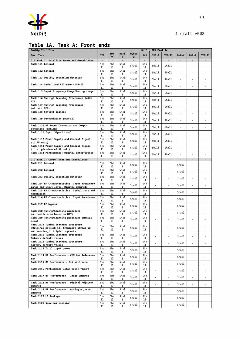
()
1 draft v002
The measurement can be performed either by using
1. the embedded BER after Viterbi measurement provided by the receiver ,or 2. watching the decoded video for 60 seconds.
If the BER after Viterbi measurement is chosen, the value for the approximation of the QEF reception is considered to correspond to the integrated BER after Viterbi decoder value 2*10-4 .The integrated BER after Viterbi measurement value 2*10-4 shall be verified that it corresponds an error free video decoding. In case of higher BER after Viterbi value than 2*10-4 , the change to the measurement configuration parameters shall be done. The change of the measurement configuration parameters shall result to a BER after Viterbi which is lower than or equal to 2*10-4 , Otherwise, the change of the measurement configuration parameters is repeated until a BER after Viterbi value lower than or equal to 2*10-4 is achieved.
If the 60 seconds error free decoded video is chosen, during this time the decoded video shall be error free. In a case of an error in decoded video, the change to the measurement configuration parameters shall be done. The change of the measurement configuration parameters shall result to an error free decoding of the video where the minimum time between consecutive subjective errors is 60 seconds. Otherwise, the change of the measurement configuration parameters is repeated until an error free decoding of video is achieved at least 60 seconds.
Indirect objective or subjective quality measurement procedure 2 (QMP2) in DVB-S2 system
The measurement can be performed either by using
1. the embedded BER after LDPC measurement provided by the receiver, or 2. watching the decoded video for 30 seconds.
If the BER after LDPC measurement is chosen, the value for the approximation of the QEF reception is considered to correspond to the integrated BER after LDPC decoder value 10-7. In case of higher BER after LDPC value than 10-7 , the change to the measurement configuration parameters shall be done. The change of the measurement configuration parameters shall result to a BER after LDPC which is lower than or equal to 10-7, Otherwise, the change of the measurement configuration parameters is repeated until the BER after LDPC value lower than or equal to 10-7 is achieved. That reception shall be verified that it corresponds an error free video decoding.
If the 30 seconds error free decoded video is chosen, during this time the decoded video shall be error free. In a case of an error in decoded video, the change to the measurement configuration parameters shall be done. The change of the measurement configuration parameters shall result to an error free decoding of the video where the minimum time between consecutive subjective errors is 30 seconds. Otherwise, the change of the measurement configuration parameters is repeated until an error free decoding of video is achieved at least 30 seconds.
Due to the nature of the DVB-S2 system forward error correction schemes the difference for the 30 seconds error free video and BER 10-7 after LDPC is very low. For practical testing the performance values are equal for both quality levels.
The corresponding measurement values for profile and DVB-S / DVB-S2 mode shall be achieved from tables below.
C/N (Es/N0) performance (dB)
Modulation Code Rate DVB-S DVB-S2
QPSK 1/4 n/a -1.4
QPSK 1/3 n/a -0.2
QPSK 2/5 n/a 0.7
QPSK 1/2 3.8 2.0
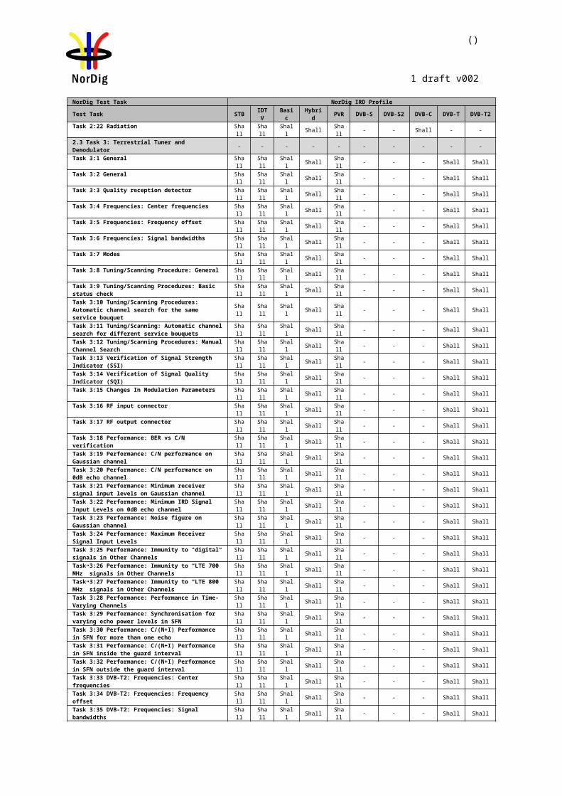
()
1 draft v002
QPSK 3/5 n/a 3.2
QPSK 2/3 5.6 4.1
QPSK 3/4 6.7 5.0
QPSK 4/5 n/a 5.7
QPSK 5/6 7.7 6.2
QPSK 7/8 8.4 n/a
QPSK 8/9 n/a 7.2
QPSK 9/10 n/a 7.4
8PSK 3/5 n/a 6.5
8PSK 2/3 n/a 7.6
8PSK 3/4 n/a 8.9
8PSK 5/6 n/a 10.4
8PSK 8/9 n/a 11.7
8PSK 9/10 n/a 12.0
C/N (Es/No) performance (dB)Modulation Code Rate DVB-S DVB-S2 DVB-S2X (3)
QPSK 1/4 n/a -1.4 (2)QPSK 13/45 n/a n/a 1.0QPSK 1/3 n/a -0.2 (2)QPSK 2/5 n/a 0.7(2)QPSK 9/20 n/a n/a 1.22QPSK 1/2 3.8 2.0QPSK 11/20 n/a n/a 2.45QPSK 3/5 n/a 3.2QPSK 2/3 5.6 4.1QPSK 3/4 6.7 5.0QPSK 4/5 n/a 5.7QPSK 5/6 7.7 6.2QPSK 7/8 8.4 n/aQPSK 8/9 n/a 7.2QPSK 9/10 n/a 7.4
8APSK-L 5/9 n/a n/a 5.738APSK-L 26/45 n/a n/a 6.13
8PSK 3/5 n/a 6.58PSK 23/36 n/a n/a 7.128PSK 2/3 n/a 7.68PSK 25/36 n/a n/a 8.028PSK 13/18 n/a n/a 8.498PSK 3/4 n/a 8.98PSK 5/6 n/a 10.48PSK 8/9 n/a 11.78PSK 9/10 n/a 12.0
16APSK-L 1/2 n/a n/a 7.4716APSK-L 8/15 n/a n/a 8.05
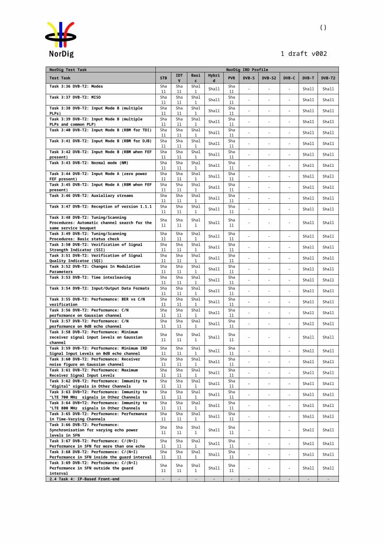
()
1 draft v002
16APSK-L 5/9 n/a n/a 8.3416APSK 26/45 n/a n/a 9.0116APSK 3/5 n/a n/a 9.3
16APSK-L 3/5 n/a n/a 8.9116APSK 28/45 n/a n/a 9.616APSK 23/36 n/a n/a 9.88
16APSK-L 2/3 n/a n/a 9.9316APSK 25/36 n/a n/a 10.7716APSK 13/18 n/a n/a 11.2116APSK 7/9 n/a n/a 12.1516APSK 77/90 n/a n/a 13.49
32APSK-L 2/3 n/a n/a 12.632APSK 32/45 n/a n/a 13.2532APSK 11/15 n/a n/a 13.6732APSK 7/9 n/a n/a 14.55
Table 2.2 Maximum C/N (Es/N0) for QEF reception (1).
Note 1: C/N measured for a bandwidth that equals the symbol rate.Quasi-Error-Free (QEF) means less than one uncorrected error event per hour, corresponding to (MPEG TS Packet Error Rate) PER= 10-7 or BER = 10-10 to 10-11 at the input of the MPEG-2 demultiplexer.
Note 2: For DVB-S2 Modes with QPSK and code rates 1/4, 1/3 and 2/5, the C/N (Es/No) values are optional (recommended) for satellite NorDig IRDs to support.
Note 3: DVB-S2X C/N (Es/No) performance only applies to satellite NorDig HEVC IRDs that supports DVB-S2X.
2.1.2 Test cases
Test Case Task 1:1 General
Section NorDig Unified 3.1.1Requirement The NorDig IRD shall include at least one tuner/demodulator unit for reception of
signals from a satelliteRF-outdoor unit.IRD Profile(s) Basic, IRD, DVB-S, DVB-S2Test procedure Purpose of test:
To verify that IRD contains at least one Tuner/demodulator
Equipment:IRD Under test
Test procedure:This is common requirement and will be verified in the following tests.
Test result(s)Conformity OK Fault Major Minor, define fail reason in commentsComments If possible describe if fault can be fixed with software update: YES NO
Describe more specific faults and/or other information
Date Sign
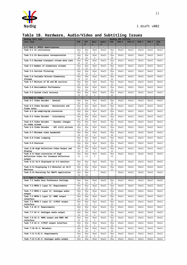
()
1 draft v002
Test Case Task 1:2 General
Section NorDig Unified 3.1.2Requirement The NorDig IRD shall be able to automatically scan through the whole frequency range
available for each of the available Tuners/Demodulators and tune in to the correct DVB framing structure, channel coding and modulation to deliver the incoming transport stream to the next units. The tuning data shall be stored in a service list, in order to allow a quick tune in to the selected transport stream.
IRD Profile(s) Basic, IRD, DVB-S, DVB-S2Test procedure Purpose of test:
To verify that IRD is able to scan throught the whole frequency range.
Test procedure:This is common requirement and will be verified in the following tests.
Test result(s) The manufacturer describes his specific setup for the testConformity OK Fault Major Minor, define fail reason in commentsComments If possible describe if fault can be fixed with software update: YES NO
Describe more specific faults and/or other information
Date Sign
Test Case Task 1:3 Quality reception detector
Section NorDig Unified 3.1.3Requirement The NorDig Unified receiver shall be equipped with a reception quality detector.
IRD Profile(s) Basic, IRD, DVB-S, DVB-S2Test procedure Equipment:
Test signal are created using the test bed shown below:
Test procedure:Check that the IRD is equipped with a reception quality detector
Expected result: It shall be possible to access some kind of a reception quality detector
Test result(s)Conformity OK Fault Major Minor, define fail reason in commentsComments If possible describe if fault can be fixed with software update: YES NO
Describe more specific faults and/or other information
Date Sign
Test Case Task 1:4 Symbol and FEC-rate (DVB-S2)
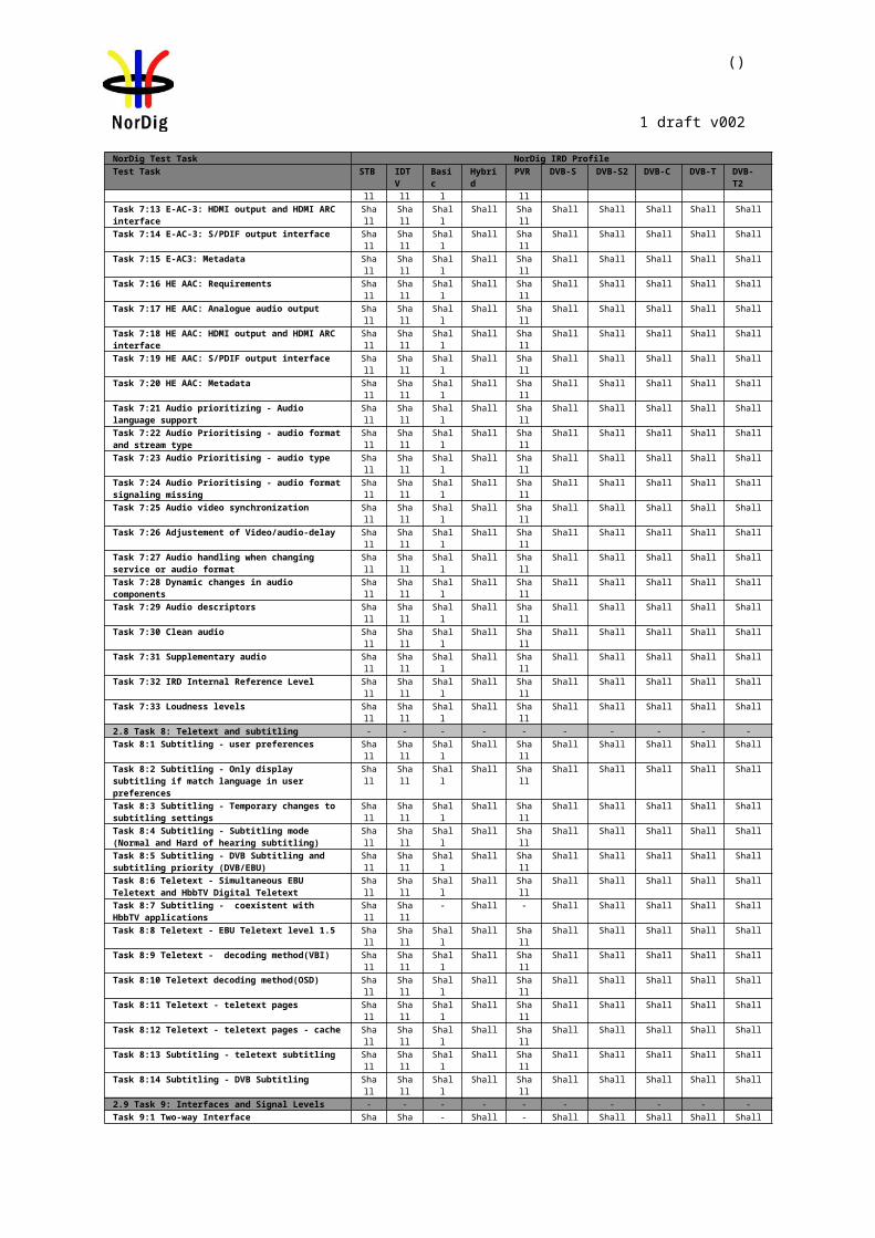
()
1 draft v002
Section NorDig Unified 3.2.2Requirement The IRD accepts symbol rates between 7.5-45 10-30 Mbaud for DVB-S carriers.
For DVB-S2 QPSK carriers the IRD accepts symbol rates between 7.5-45 Mbaud
For DVB-S2 8PSK carriers the IRD accepts symbol rates between 5-30 Mbaud
IRD Profile(s) Basic, IRD, DVB-S, DVB-S2Test procedure Purpose of test:
To verify that the IRD accepts a transport stream with a symbol rate in the required range 10 – 30 Mbaud
Equipment:Test signals are created using the test bed shown below:
Test procedure:
1. Configure wanted signal to center frequency 1500 MHz, DVB-S QPSK, 7.5Mbaud at level -45dBm.
2. Power on IRD.3. Make a channel search at wanted signal and verify that IRD locks to carrier and
decodes picture without any visible degradation.4. Use quality measurement procedure 2 (QMP2).5. Repeat the test for the symbol rates and FEC modes in the measurement record.
Expected result: IRD locks to carrier and decodes picture without any visible degradation.
Test result(s) Measurement record
Result OK/NOK:DVB-S QPSK carrierFEC rate Symbol rate
7.5 MbaudSymbol rate45 Mbaud
1/22/33/45/67/8
DVB-S2 QPSK carrier (Pilots off)FEC rate Symbol rate
7.5 MbaudSymbol rate45 Mbaud
1/41/32/51/23/52/3
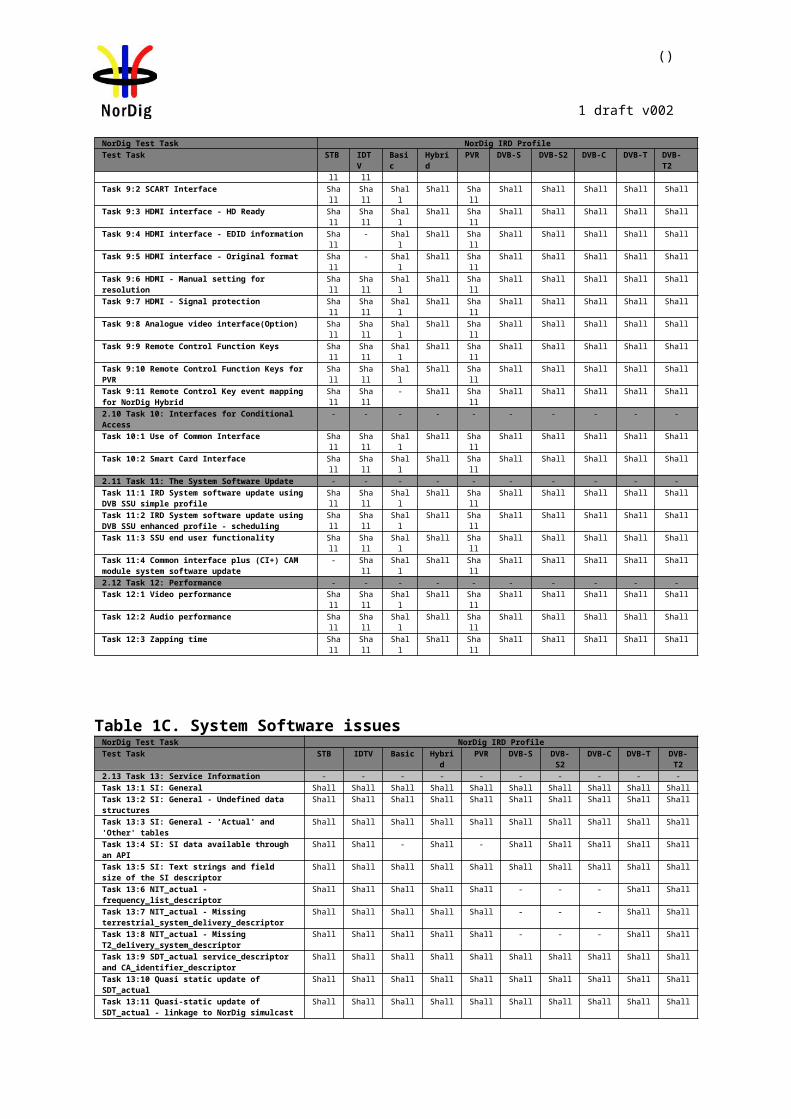
()
1 draft v002
3/44/55/68/99/10
DVB-S2 8PSK carrier (Pilots on)FEC rate Symbol rate
5 MbaudSymbol rate30 Mbaud
3/52/33/45/68/99/10
S2X figures not included
Conformity OK Fault Major Minor, define fail reason in commentsComments If possible describe if fault can be fixed with software update: YES NO
Describe more specific faults and/or other information
Date Sign
Test Case Task 1:5 Input Frequency Range/Tuning range
Section NorDig Unified 3.2.3Requirement IRD locks to carrier and decodes picture without any visible degradation.IRD Profile(s) Basic, IRD, DVB-S, DVB-S2Test procedure Purpose of test:
To verify that IRD accepts an input signal in the range 950 – 2150 MHz
Equipment:Test signals are created using the test bed shown below:
Test procedure:
1. Configure wanted signal to center frequency 10715 MHz, DVB-S QPSK, FEC=7/8, 30Mbaud at level -45dBm.
2. Power on IRD.3. Configure Universal LNBF in the IRD settings (f(LO)=9750/10600). 4. Make a channel search at wanted signal and verify that IRD locks to carrier and
decodes picture without any visible degradation.5. Use quality measurement procedure 2 (QMP2).
Repeat the test for the centre frequencies in the measurement record.
Expected result: IRD locks to carrier and decodes picture without any visible degradation.
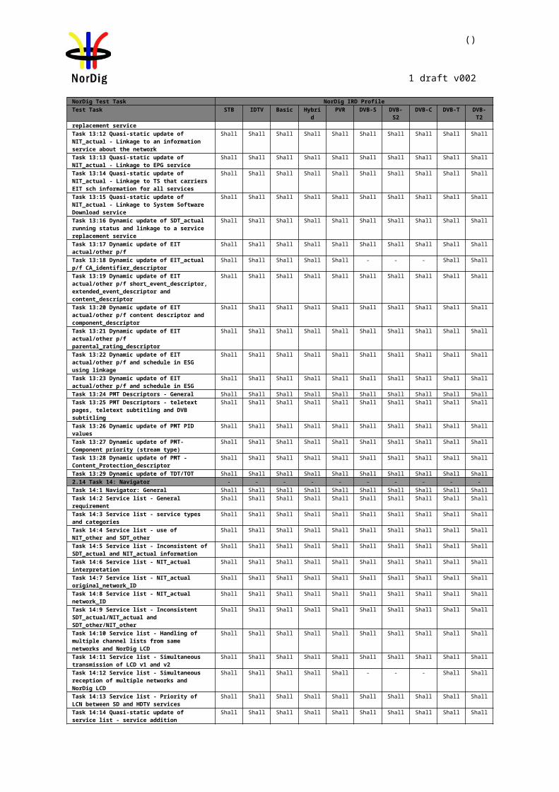
()
1 draft v002
Test result(s) Measurement record:
IF frequency [MHz]
LO frequency [MHz]
Centre frequency [MHz]
Polarisation (H/V)
Result OK/NOK
965 9750 10715 H965 9750 10715 V1949 9750 11699 H1949 9750 11699 V1100 10600 11700 H1100 10600 11700 V2135 10600 12735 H2135 10600 12735 V
Conformity OK Fault Major Minor, define fail reason in commentsComments If possible describe if fault can be fixed with software update: YES NO
Describe more specific faults and/or other information
Date Sign
Test Case Task 1:6 Tuning/ Scanning Procedures (with NIT)
Section NorDig Unified 3.2.6Requirement The NorDig IRD shall either use the NIT information or the scanning procedure for
retrieving the servicesavailable on the network.IRD Profile(s) Basic, IRD, DVB-S, DVB-S2Test procedure Purpose of test:
To verify that the IRD use tuning data given in NIT.
Equipment:IRD under test, with service list deleted and using the test bed shown below:
Test procedure:Start automatic tuning and installation of services, using Network Information Tables (NIT), and check found and installed channels.
Expected result:All signalled channels are found and installed.
Test result(s)Conformity OK Fault Major Minor, define fail reason in commentsComments If possible describe if fault can be fixed with software update: YES NO
Describe more specific faults and/or other information
Date Sign
Test Case Task 1:7 Tuning/ Scanning Procedures (without NIT)
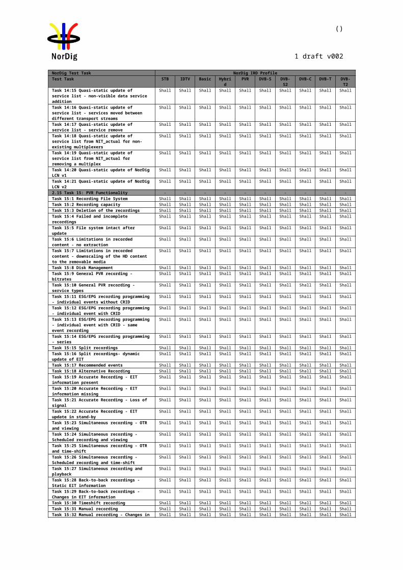
()
1 draft v002
Section NorDig Unified 3.2.6Requirement The NorDig IRD shall either use the NIT information or the scanning procedure for
retrieving the servicesavailable on the network.IRD Profile(s) Basic, IRD, DVB-S, DVB-S2Test procedure Purpose of test:
To verify that the IRD searches for - and installs services - without ‘a priori’ NIT information.
Equipment:IRD under test, with service list deleted and using the test bed shown below:
Test procedure:Start automatic tuning and installation of services, without Network Information Tables (NIT), and check found and installed channels.
Expected result:All signalled channels are found and installed.
Test result(s)Conformity OK Fault Major Minor, define fail reason in commentsComments If possible describe if fault can be fixed with software update: YES NO
Describe more specific faults and/or other information
Date Sign
Test Case Task 1:8 Control signals
Section NorDig Unified 3.2.5Requirement The Tuner/Demodulator shall be able to select between at least two RF units, upper and
lower band aswell as polarisation within each unit in accordance with EN 61319-1 [13], level 1 (the “DiSEqC” specification, level 1.0).
IRD Profile(s) Basic, IRD, DVB-S, DVB-S2Test procedure Purpose of test:
To verify that the IRD is able to select between two RF-units.
Equipment:DTH antenna with dual-feed Universal LNBs, pointed at i.e.‘1 degree W’ and ‘5 degree E’ or test signals are created using the test bed shown below:
A DiseqC-switch is used to select between the LNBs.
Test procedure:Check that tuning to carriers in both ‘1 degree W’ and ‘5 degree E’ (or test bed signals) is
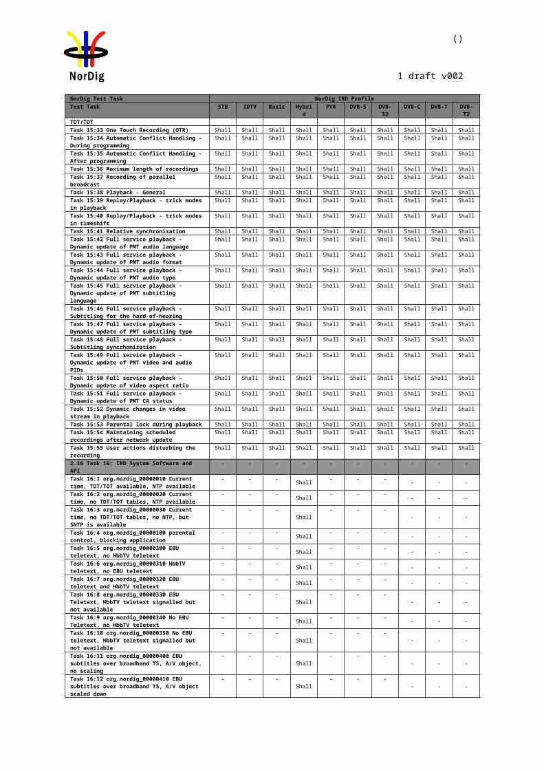
()
1 draft v002
possible by DiseqC command.
Expected result:All signalled channels are are installed and IRD decodes picture and sound without any visible degradation.
Test result(s)Conformity OK Fault Major Minor, define fail reason in commentsComments If possible describe if fault can be fixed with software update: YES NO
Describe more specific faults and/or other information
Date Sign
Test Case Task 1:9 Demodulation (DVB-S2)
Section NorDig Unified 3.2.4Requirement Demodulation, descrambling and error correction shall be performed for all symbol rates
given above andfor all error correction rates and filter roll-off rates as specified for DVB-S, see EN 300 421 [14] and for DVB-S2, see ETSI EN 302 307 [23] and the satellite_delivery_system_descriptor, see Table 13.1.
IRD Profile(s) Basic, IRD, DVB-S2Test procedure Purpose of test:
To verify the basic performance of the IRD.
Equipment:Test signals are created using the test bed shown below:
Test procedure:1. Configure wanted signal to center frequency 1500 MHz, DVB-S QPSK,
FEC=1/2, 10Mbaud at level -60dBm.2. Power on IRD.3. Make a channel search at wanted signal and verify that IRD locks to carrier and
decodes picture without any visible degradation.4. Increase the C/N from low value to higher value until the QMP2 criteria fulfills.5. Fill in the C/N value to the measurement record table.6. Repeat the test for all modulation, FEC and symbol rate combinations in the
measurement record tables.
Note: C/N measured for a bandwidth that equals the symbol rate (Es/N0=C/N).
Expected result: IRD decodes picture and sound without any visible degradation. IRD meets the requirements of Nordig Unified 3.1 section 3.2.4 and IRD Es/No performance meets the requirements of Nordig Unified 3.1 section 3.2.8.
Test result(s)Measurement record:
DVB-S QPSK, Roll-off=0.35:FEC Pin=-460dBm Pin=-25dBm Pin=-60dBm Pin=-25dBm
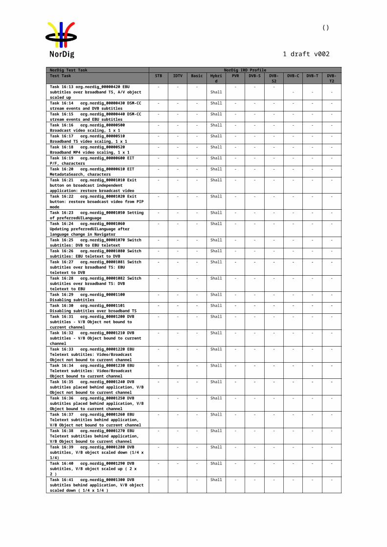
()
1 draft v002
SR=310MbaudMeasured C/N
SR=10MbaudMeasured C/N
SR=30MbaudMeasured C/N
SR=30MbaudMeasured C/N
1/22/33/45/67/8
DVB-S2 QPSK, Roll-off=0.25, Pilots=Enabled, FECframe=64800FEC Pin=-60dBm
SR=10MbaudMeasured C/N
Pin=-25dBmSR=10MbaudMeasured C/N
Pin=-60dBmSR=30MbaudMeasured C/N
Pin=-25dBmSR=30MbaudMeasured C/N
1/41/32/51/23/52/33/44/55/68/99/10
DVB-S2 QPSK, Roll-off=0.25, Pilots=Disabled, FECframe=64800FEC Pin=-640dBm
SR=130MbaudMeasured C/N
Pin=-25dBmSR=10MbaudMeasured C/N
Pin=-60dBmSR=30MbaudMeasured C/N
Pin=-25dBmSR=30MbaudMeasured C/N
1/41/32/51/23/52/33/44/55/68/99/10
DVB-S2 8PSK, Roll-off=0.25, Pilots=Enabled, FECframe=64800FEC Pin=-60dBm
SR=10MbaudMeasured C/N
Pin=-25dBmSR=10MbaudMeasured C/N
Pin=-60dBmSR=30MbaudMeasured C/N
Pin=-25dBmSR=30MbaudMeasured C/N
3/52/33/45/68/99/10
DVB-S2 8PSK, Roll-off=0.25, Pilots=Disabled, FECframe=64800FEC Pin=-640dBm
SR=130MbaudMeasured C/N
Pin=-25dBmSR=10MbaudMeasured C/N
Pin=-60dBmSR=30MbaudMeasured C/N
Pin=-25dBmSR=30MbaudMeasured C/N
3/5
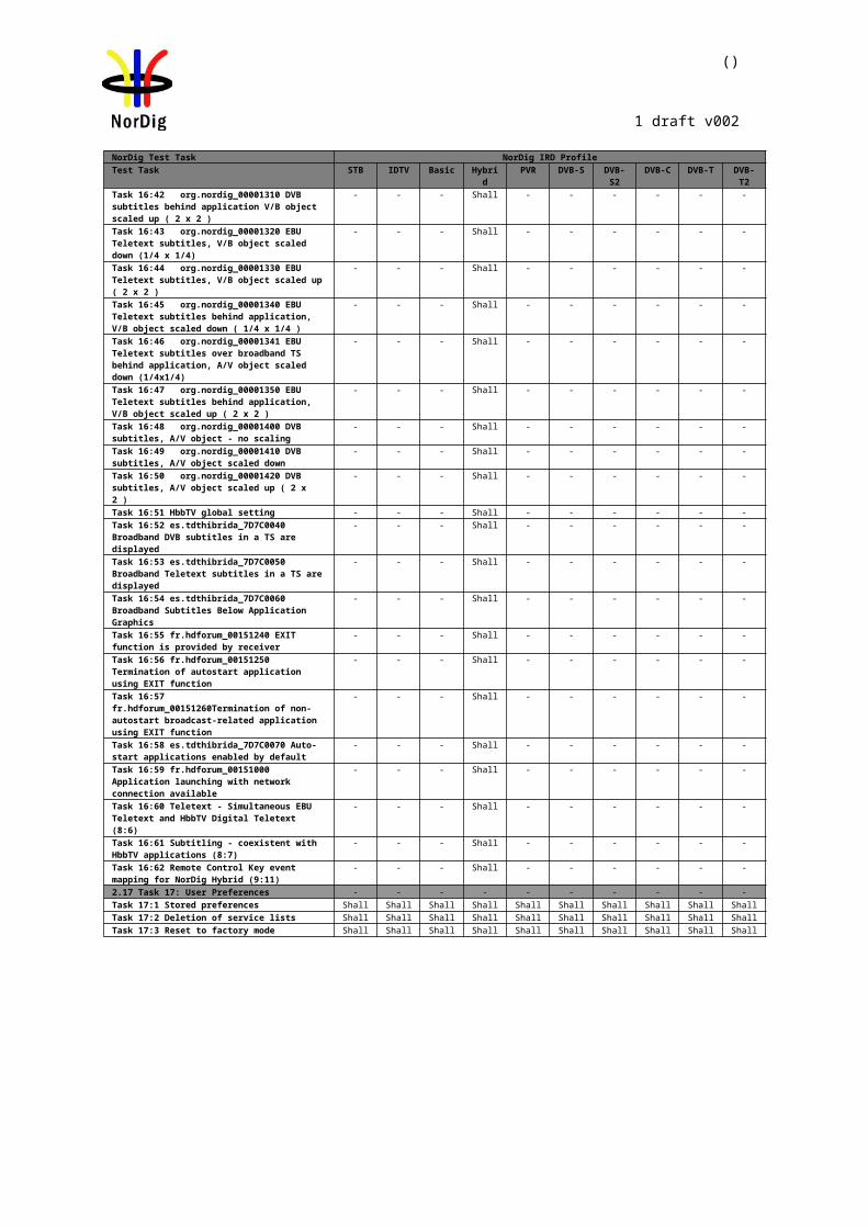
()
1 draft v002
2/33/45/68/99/10
Note tables above prepared for test reduction after inclusion of S2X modes
Conformity OK Fault Major Minor, define fail reason in commentsComments If possible describe if fault can be fixed with software update: YES NO
Describe more specific faults and/or other information
Date Sign
Test Case Task 1:10 RF Input Connector and Output Connector (option)
Section NorDig Unified 3.2.7.1Requirement The NorDig IRD shall include one input connector, type: IEC 61169-24, F-type, female,
75 ohms.The NorDig IRD should include one output connector, type: IEC 61169-24, F-type, female, 75 ohms.The RF output shall be available independently from the operational status of the IRD (operational or stand by), so that there is no restriction for the operation of the connected equipment. The control of the RF unit has to be solved for the case with one or more additional IRDs.
IRD Profile(s) Basic, IRD, DVB-S, DVB-S2Test procedure Purpose of test:
To verify that the receiver has a correct input connector for the reception of the DVB-S signals.
Equipment:IRD under test.
Test procedure:1. Verify that the RF input and output connectors are accordance the specification
IEC 61169-24, F-type, female. 2. Verify in the manufacturer’s technical specification that the input impedance of
the RF input is 75 ohm and the return loss is typically 10dB, worst case 8dB.
Expected result:RF input connector is as defined in specification IEC 61169-24 and the input impedance is 75ohm.
Test result(s)Conformity OK Fault Major Minor, define fail reason in commentsComments If possible describe if fault can be fixed with software update: YES NO
Describe more specific faults and/or other information
Date Sign
()
1 draft v002
Test Case Task 1:11 Input Signal Level
Section NorDig Unified 3.2.7.2Requirement The NorDig IRD shall accept input signals with a level in the range -25 to -60 dBm.IRD Profile(s) Basic, IRD, DVB-S, DVB-S2Test procedure Purpose of test:
To verify that the receiver can receive input signals with a level in the range -25 to -650 dBm.
Equipment:Test signals are created using the test bed shown below:
Test procedure:1. Configure wanted signal to IF frequency 965 MHz, DVB-S QPSK, FEC=7/8,
30Mbaud at level -650dBm.2. Power on IRD.3. Make a channel search at wanted signal. 4. Verify that IRD locks to carrier and decodes picture without any visible
degradation (meets QMP2).5. Increase the wanted signal level to -25dBm.6. Verify that IRD locks to carrier and decodes picture without any visible
degradation (meets QMP2).
Repeat the test for the centre frequencies and modes in the measurement record.
Expected result:IRD decodes picture and sound without any visible degradation.
Test result(s) Measurement record:
DVB-S QPSK FEC=7/8 SR=30Msym/sIF frequency
[MHz]Min signal
level [dBm]
Max signal level [dBm]
9652135
DVB-S2 QPSK FEC=9/10 SR=30Msym/s, Roll-off: 0.25, Pilots On IF frequency
[MHz]Min signal
level [dBm]
Max signal level [dBm]
9652135
DVB-S2 QPSK FEC=9/10 SR=30Msym/s, Roll-off: 0.25, Pilots Off IF frequency
[MHz]Min signal
level [dBm]
Max signal level [dBm]
9652135
()
1 draft v002
DVB-S 8PSK FEC=9/10 SR=30Msym/s, Roll-off: 0.25, Pilots OnIF frequency
[MHz]Min signal
level [dBm]
Max signal level [dBm]
9652135
DVB-S 8PSK FEC=9/10 SR=30Msym/s, Roll-off: 0.25, Pilots OffIF frequency
[MHz]Min signal
level [dBm]
Max signal level [dBm]
9652135
Conformity OK Fault Major Minor, define fail reason in commentsComments If possible describe if fault can be fixed with software update: YES NO
Describe more specific faults and/or other information
Date Sign
Test Case Task 1:12 Power Supply and Control Signal (to RF unit)
Section NorDig Unified 3.2.7.3Requirement The NorDig IRD shall provide power supply and control signals to the external RF-unit as
specified below: voltage: 13.5/18.5 V+/- 5% current: at least 400 mA control tone: amplitude: 0.65 V +/- 0.25V
frequency: 22 kHzduty cycle: 50% +/- 10%
(see also ref EN 61319-1 (DiSEqC).
IRD Profile(s) Basic, IRD, DVB-S, DVB-S2
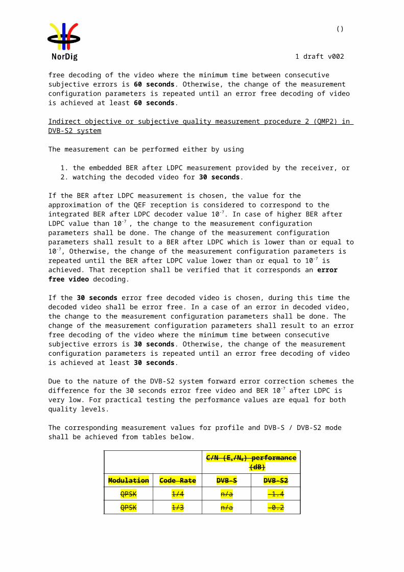
()
1 draft v002
Test procedure Purpose of test:To verify that power supply and control signals to the external RF-unit are as specified.
Equipment:
Test procedure:Measure voltage, current and control tone from external RF unit connector.
1. Configure the IRD to the lower Ku band frequency, e.g. transmission parameters DVB-S QPSK f=10750MHz, FEC=7/8, horizontal polarization, using LNB f(LO)=9750/10600MHz
2. Measure the following characteristics at the receiver RF inputa. LNB supply DC voltageb. DC currentc. Control tone frequencyd. Control tone peak-to-peak voltagee. Control tone duty cyclef. Control tone rise and fall times
3. Fill in the measurement record4. Repeat the test for other parameter combinations in the measurement record.
Expected result:The IRD provides power supply and control signals to the external RF-unit as specified.
Test result(s) Measurement record:
f(RF)[MHz]
Polarisation (H/V)
LNB supply voltage VDC
IDC fCTRL VPP,CTRL
DCTRL tR tF
10750 H10750 V12600 H12600 V
Conformity OK Fault Major Minor, define fail reason in commentsComments If possible describe if fault can be fixed with software update: YES NO
Describe more specific faults and/or other information
Date Sign
Test Case Task 1:13 Power Supply and Control Signal (to single-channel RF unit)
Section NorDig Unified 3.2.5, NorDig Unified 3.2.7.3Requirement The Tuner/Demodulator shall be able to select transport stream in accordance with EN
50494 Satellite [10] (”Signal distribution over a single coaxial cable in single dwelling in-stallations
IRD Profile(s) Basic, IRD, DVB-S, DVB-S2
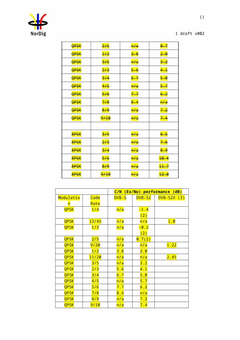
()
1 draft v002
Test procedure Purpose of test:To verify that power supply and control signals to the external RF-unit are as specified.
Equipment:
Test procedure:
TBD
Expected result:TBD
Test result(s)Conformity OK Fault Major Minor, define fail reason in commentsComments If possible describe if fault can be fixed with software update: YES NO
Describe more specific faults and/or other information
Date Sign
Test Case Task 1:14 Performance: Digital interference
Section NorDig Unified 3.2.8Requirement IRD decodes picture and sound without any visible degradation.IRD Profile(s) Basic, IRD, DVB-S, DVB-S2Test procedure Purpose of test:
To verify the performance of the IRD in a multi-carrier environment.
Equipment:Test signals are created using the test bed shown below:
Test procedure:UACI/LACI: Symbol rate and power equal to wanted carrier. Frequency separation from wanted carrier: +/- 1.25 SR for DVB-S carriers and +/- 1.2 SR for DVB-S2 carriers.
Verify that IRD can receive input signals with a level in the range -25 to -650 dBm1. Configure wanted signal to IF frequency 1500 MHz, DVB-S QPSK, FEC=7/8,
10Mbaud at level -650dBm and interferer signal on f(IF)+1.25SR = 1512,5 MHz with power level and transmission parameters equal to the wanted signal.
2. Power on IRD.3. Make a channel search at wanted signal and verify that IRD locks to carrier and
decodes picture without any visible degradation.4. Apply Gaussian noise over the wanted signal so that reception is not possible.
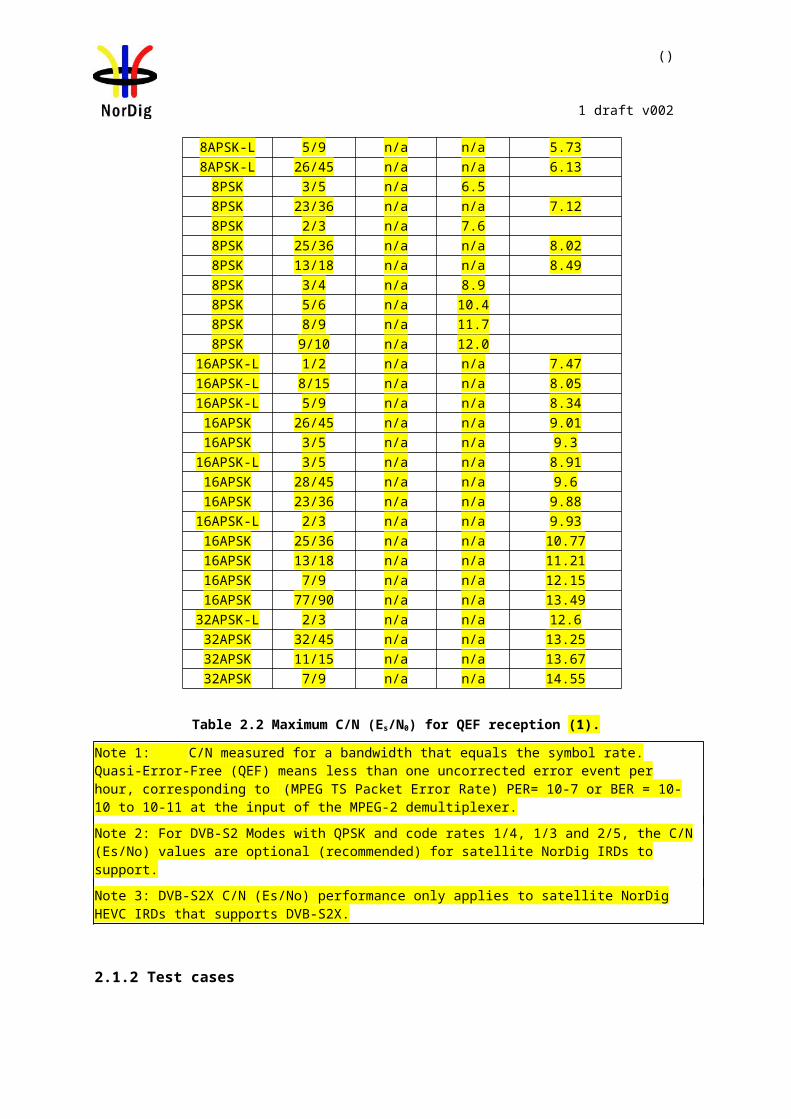
()
1 draft v002
5. Increase the C/N from low value to higher value until the reception quality meets QMP2.
6. Fill in the result in the measurement record.
Repeat the test for the centre frequencies and modes in the measurement record.
Expected result:IRD decodes picture and sound without any visible degradation. The minimum Es/No meets the requirement in NorDig Unified specification [1] with 0.45dB allowance.
Test result(s) Measurement record
DVB-S QPSK FEC=7/8, Roll-off=0.35, Channel spacing = 1.25xSR
Symbol Rate
[Mbaud]
IF frequency interferer [MHz]
IF frequency wanted[MHz]
Es/No (C/N) level [dB]
10 1512,5 150010 1487,5 147530 1537,5 1501.5 150030 1462,5 1426.5 1425
DVB-S2 QPSK FEC=9/10, Roll-off=0.25, Channel spacing = 1.20xSR, Pilots ON
Symbol Rate
[Mbaud]
IF frequency interferer [MHz]
IF frequency wanted[MHz]
Es/No (C/N) level [dB]
10 1512 150010 1488 147630 1536 150030 1464 1428
DVB-S2 QPSK FEC=9/10, Roll-off=0.25, Channel spacing = 1.20xSR, Pilots OFF
Symbol Rate
[Mbaud]
IF frequency interferer [MHz]
IF frequency wanted[MHz]
Es/No (C/N) level [dB]
10 1512 150010 1488 147630 1536 150030 1464 1428
DVB-S2 8PSK FEC=9/10, Roll-off=0.25, Channel spacing = 1.20xSR, Pilots ON
Symbol Rate
[Mbaud]
IF frequency interferer [MHz]
IF frequency wanted[MHz]
Es/No (C/N) level [dB]
10 1512 150010 1488 147630 1536 150030 1464 1428
DVB-S2 8PSK FEC=9/10, Roll-off=0.25, Channel spacing = 1.20xSR, Pilots OFF
Symbol RateIF frequency interferer
IF frequency wanted
Es/No (C/N) level [dB]
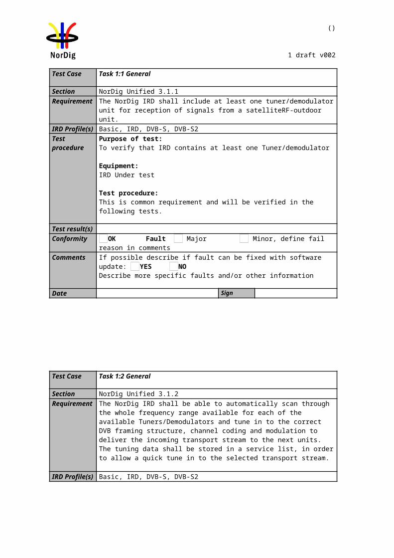
()
1 draft v002
[Mbaud]
[MHz] [MHz]
10 1512 150010 1488 147630 1536 150030 1464 1428
Conformity OK Fault Major Minor, define fail reason in commentsComments If possible describe if fault can be fixed with software update: YES NO
Describe more specific faults and/or other information
Date Sign
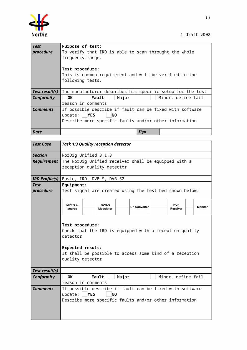
()
1 draft v002
2.2 Task 2: Cable Tuner and Demodulator
2.2.1 QEF Quality Measurement Methods
The quality limit in this specification is defined as Quasi Error Free (QEF) reception, where QEF means less than one uncorrected error event per hour. The definition of QEF corresponds to BER of 10-11 in the TS data at input of the MPEG-2 demultiplexer. In practice, it takes long time to measure such a low BER at TS data level. Therefore, the reception quality can be evaluated either indirectly by
measuring the BER after Viterbi in DVB-C system, or subjectively inspecting the video screen for a certain period of time and looking for errors in the
decoded video.
Direct measurements on the TS data packets are the preferred measurement method, but if this is not possible or acceptable for some reason, the indirect measurements can be used. The indirect measurement methods, which can be used, are objective BER measurements described above or subjective quality measurement.
In the indirect objective method in the DVB-C system, the BER of 2*10-4 after Viterbi decoder is considered to correspond to an approximation of QEF reception quality for Gaussian type of channels. But for channels interfered by impulse like interference i.e. PAL signals or internal interference, the average BER of 2*10-4 after Viterbi decoder is not valid due to the fact that the RS decoder is not able to correct the burst of errorneous bytes caused by impulse like interference. Therefore, for impulse like interfered channels, the quality measurements shall be done by using the BER of 10-11 measurement method at the TS level at MPEG-2 demultiplexer input or by using the subjective measurement method.
In the indirect subjective measurement method the certain period of time of error free video decoding is considered to corresponds to a good reception quality. The specified video test sequence can be any containing movement everywhere, in order to minimise the number of errors not being observed due to error concealment techniques in the receiver. Such a relevant video sequences are e.g. ‘Mobile and calendar’ and ‘Zoneplate’.
The result of the indirect quality measurements may differ. Therefore, the method that shall be used is specified in every test case. However, the reception quality shall be verified by using the subjective measurement method for every test case. The measurement methods (procedures) are defined below.
Direct objective quality measurement procedure in DVB-C systems
The measurement is performed doing measurements at the transport stream data level. The measurement configuration parameters are chosen like that there is less than one uncorrected error event per hour. This requirement corresponds to BER value 10-11 at the TS data level at the input of the MPEG-2 demultiplexer. In addition to the BER measurement, the reception quality shall be verified subjectively.
The performance in every test case can be evaluated by using the direct quality measurement procedure.
Indirect subjective quality measurement procedure 1 (QMP1) in DVB-C systems
The subjective measurement is performed during 15 seconds. During this time the decoded video shall be error free. In a case of an error in decoded video, the change to the measurement configuration parameters shall be done. The change of the measurement configuration parameters shall result to an error free decoding of the video where the minimum time between consecutive subjective errors is 15 seconds. Otherwise, the change of the measurement configuration parameters is repeated until an error free decoding of video is reached at least 15 seconds.
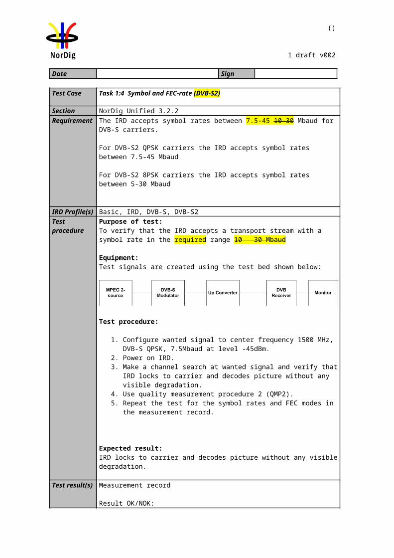
()
1 draft v002
Indirect objective or subjective quality measurement procedure 2 (QMP2) in DVB-C system
The measurement can be performed either by using
3. the embedded BER after Viterbi measurement provided by the receiver ,or 4. watching the decoded video for 60 seconds.
If the BER after Viterbi measurement is chosen, the value for the approximation of the QEF reception is considered to correspond to the integrated BER after Viterbi decoder value 2*10-4 .The integrated BER after Viterbi measurement value 2*10-4 shall be verified that it corresponds an error free video decoding. In case of higher BER after Viterbi value than 2*10-4 , the change to the measurement configuration parameters shall be done. The change of the measurement configuration parameters shall result to a BER after Viterbi which is lower than or equal to 2*10-4 , Otherwise, the change of the measurement configuration parameters is repeated until a BER after Viterbi value lower than or equal to 2*10-4 is achieved.
If the 60 seconds error free decoded video is chosen, during this time the decoded video shall be error free. In a case of an error in decoded video, the change to the measurement configuration parameters shall be done. The change of the measurement configuration parameters shall result to an error free decoding of the video where the minimum time between consecutive subjective errors is 60 seconds. Otherwise, the change of the measurement configuration parameters is repeated until an error free decoding of video is achieved at least 60 seconds.
2.2.2 Test cases
Test Case Task 2:1 General
Section NorDig Unified 3.1.1Requirement The NorDig IRD shall contain at least one Tuner/Demodulator for cable DVB/MPEG 2
signals.
IRD profile(s) Basic, IRD, DVB-CTest procedure Purpose of test:
To verify that IRD contains at least one Tuner/demodulator
Equipment:IRD Under test.
Test procedure:This is common requirement and will be verified in the following tests.
Test result(s)Conformity OK Fault Major Minor, define fail reason in commentsComments If possible describe if fault can be fixed with software update: YES NO
Describe more specific faults and/or other information
Date Sign
Test Case Task 2:2 General
Section NorDig Unified 3.1.2Requirement The NorDig IRD shall be able to automatically scan through the whole frequency range
available for each of the available Tuners/Demodulators and tune in to the correct DVB framing structure, channel coding and modulation to deliver the incoming transport stream to the next units. The tuning data shall be stored in a service list, in order to allow a quick tune in to the selected transport stream. For more detail see below.
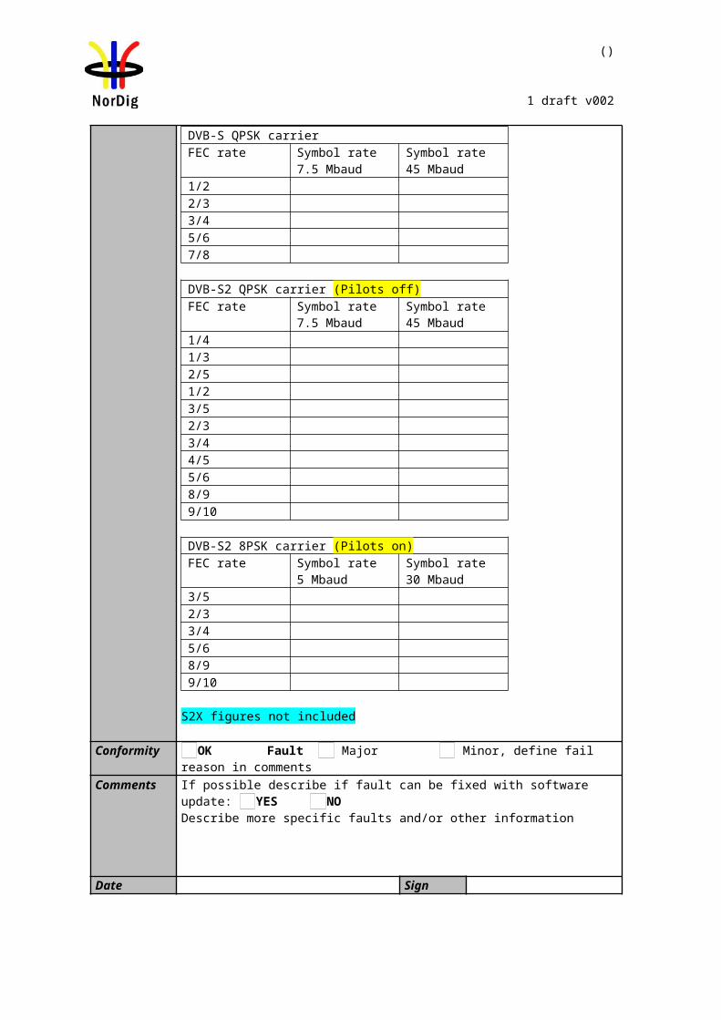
()
1 draft v002
IRD profile(s) Basic, IRD, DVB-CTest procedure Purpose of test:
To verify that IRD is able to scan throught the whole frequency range.
Test procedure:This is common requirement and will be verified in the following tests.
Test result(s) The manufacturer describes his specific setup for the testConformity OK Fault Major Minor, define fail reason in commentsComments If possible describe if fault can be fixed with software update: YES NO
Describe more specific faults and/or other information
Date Sign
Test Case Task 2:3 Quality reception detector
Section NorDig Unified 3.1.3Requirement The NorDig Unified receiver shall be equipped with a reception quality detector.
IRD profile(s) Basic, IRD, DVB-CTest procedure Test procedure:
Check that the IRD is equipped with a reception quality detector
Expected result: It shall be possible to access some kind of a reception quality detector
Test result(s)Conformity OK Fault Major Minor, define fail reason in commentsComments If possible describe if fault can be fixed with software update: YES NO
Describe more specific faults and/or other information
Date Sign
Test Case Task 2:4 RF Characteristics: Input frequency range and input level, Digital channels
Section NorDig Unified 3.3.2Requirement The IRD shall have RF characteristics equal to or better than specified below: Input
Frequency range: Digital signals 110 - 862 MHz
IRD profile(s) Basic, IRD, DVB-C
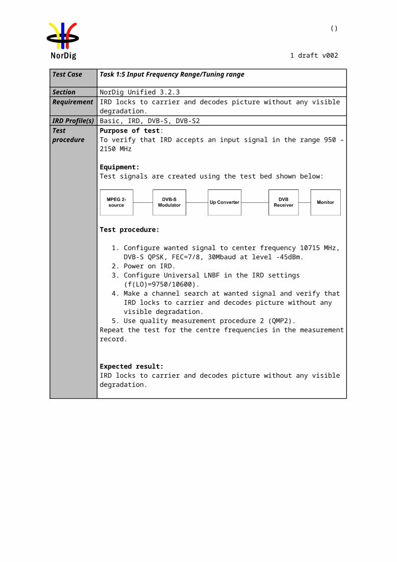
()
1 draft v002
Test procedure Equipment:
Test procedure:6. Configure wanted signal to center frequency 114 MHz, 16 QAM, SR 6.952
Msymb/s at level 60 dBµV.7. Power on IRD.8. Make a channel search at wanted signal and verify that IRD locks to carrier and
decodes picture without any visible degradation.9. Use quality measurement procedure 2 (QMP2).10. Repeat the test for the signal levels, center frequencies and DVB-C modes in
the measurement record.Expected result: IRD locks to carrier and decodes picture without any visible degradation
Test result(s)Measurement record
Result OK/NOK:
Frequency114 MHz 858 MHz
Modulation / Signal Level [dBμV]
60 47 77 60 47 77
16 QAM128 QAM256 QAMModulation / Signal Level [dBμV]
60 43 73 60 43 73
64 QAM
Conformity OK Fault Major Minor, define fail reason in commentsComments If possible describe if fault can be fixed with software update: YES NO
Describe more specific faults and/or other information
Date Sign
Test Case Task 2:5 RF Characteristics: Symbol rate and modulation
Section NorDig Unified 3.3.2Requirement The IRD shall have RF characteristics equal to or better than specified below:
Symbolrate: Digital signals 4 Msymbols/s to 7 Msymbols/s. The rates are set in steps of 1 ksymbols/s.Modulation: Digital signals 16-QAM, 64-QAM, 128-QAM and 256-QAM
IRD profile(s) Basic, IRD, DVB-C
Digital Video
generator
IRD Under test
Multiplexer
Digital TV test
transmitter
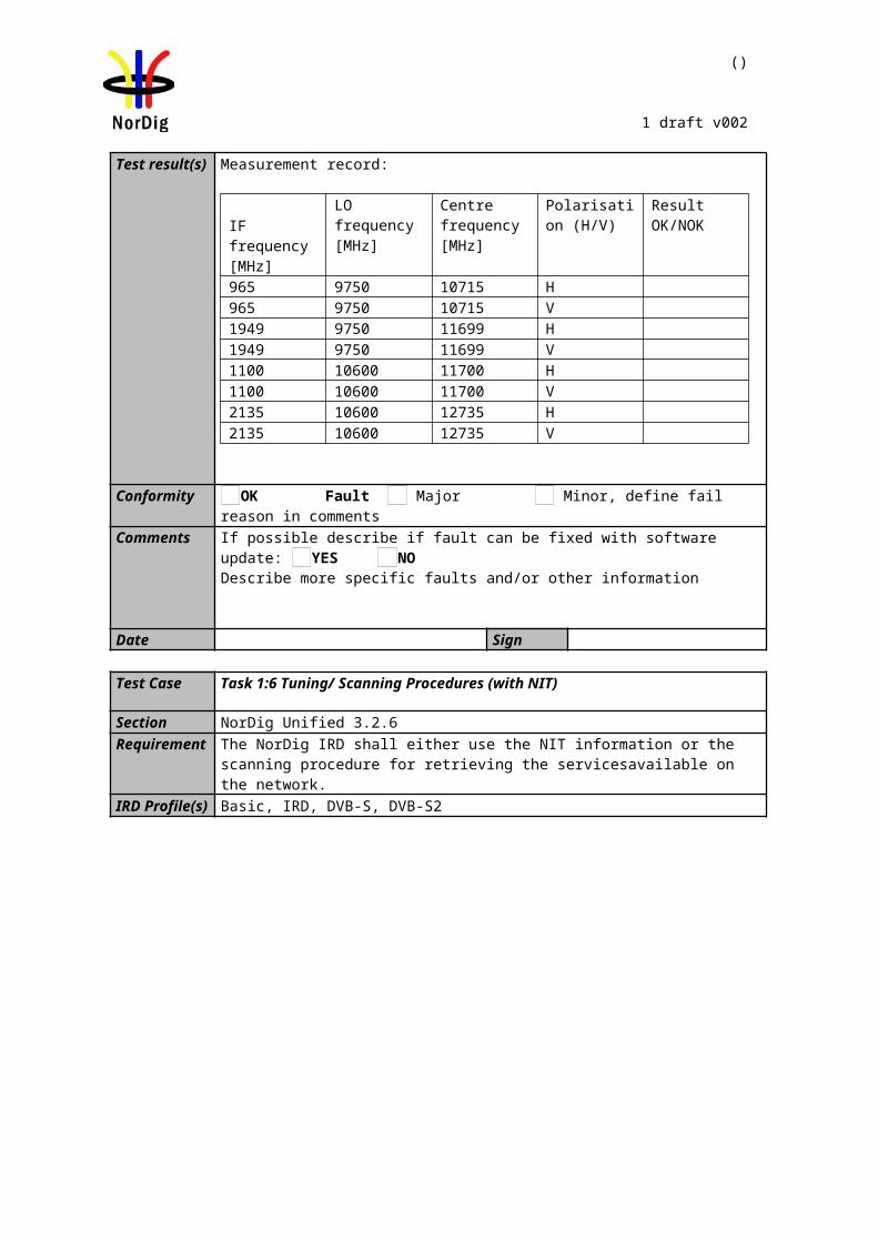
()
1 draft v002
Test procedure Equipment:Digital Video Generator TV test transmitter for cable
Test procedure:1. Configure wanted signal to center frequency 666 MHz, 16 QAM, SR 4.000
Msymb/s at level 60 dBµV.2. Power on IRD.3. Make a channel search at wanted signal and verify that IRD locks to carrier and
decodes picture without any visible degradation.4. Use quality measurement procedure 2 (QMP2).5. Repeat the test for the DVB-C modes in the measurement record.
Expected result: IRD locks to carrier and decodes picture without any visible degradation and the symbol rate is settable in 1 ksymbols/s steps.
Test result(s) Measurement record
Status OK/NOK:Modulation / Symbol Rate [Msymb/s]
4.000 4.100 7.000
16 QAM64 QAM128 QAM256 QAM
Conformity OK Fault Major Minor, define fail reason in commentsComments If possible describe if fault can be fixed with software update: YES NO
Describe more specific faults and/or other information
Date Sign
Test Case Task 2:6 RF Characteristics: Input impedance
Section NorDig Unified 3.3.2Requirement The IRD shall have RF characteristics equal to or better than specified below:
Input connector : IEC 61169-2, female, 75 OhmsIRD profile(s) Basic, IRD, DVB-CTest procedure
The manufacturer verifies that the input impedance is 75 Ohms.
Test result(s)Conformity OK Fault Major Minor, define fail reason in commentsComments If possible describe if fault can be fixed with software update: YES NO
Describe more specific faults and/or other information
Digital Video
generator
IRD Under test
Multiplexor
Digital TV test
transmitter
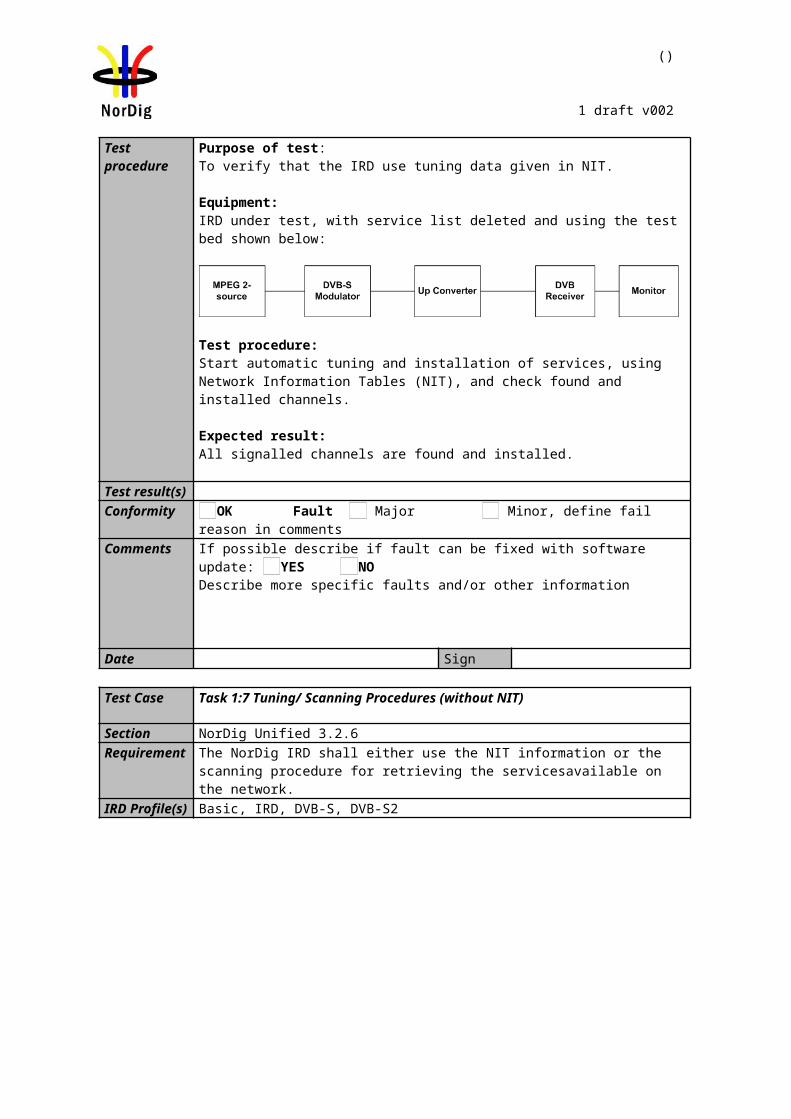
()
1 draft v002
Date Sign
Task 2:7 RF bypass
Section NorDig Unified 3.3.3Requirement The RF signals should be bypassed from RFin to RFout independently from the status of
the NorDig IRD (operational or stand by), so that connected equipment can operate even if the NorDig IRD is in stand by.
The frequency range for the RF bypass shall be from 47 MHz to 862 MHz.The NorDig IRD, when equipped with RF bypass, should include user setting to disable or enable the RF bypass gain in stand-by mode. When the RF bypass gain is disabled, the maximum RF bypass gain should -4dB and when the RF bypass gain is enabled, the RF bypass gain should be from –1 dB to +3 dB.The degradation of the signals caused by the RF bypass compared to the input signal shall be less than:o 1 dB in case of signal-to-noise ratio
IRD profile(s) Basic, IRD, DVB-CTest procedure Purpose of test:
To verify that IRDs RF bypass is according the specification.
Equipment:IRD Under testMeasurement equipment
Test procedure:1. Generate one digital channel (64 QAM, 6,952 MS/s, 015 roll-off) at 114 MHz
with three different input levels, 60 dBµV, 43 dBµV and 73 dBµV.
2. Verify that the RFout signal level is less than 1dB below and less than 3dB above the signal level at the RFin
3. Generate one digital channel (64 QAM, 6,952 MS/s, 015 roll-off) at 858 MHz. Make the test for three different input levels, 60 dBµV, 43 dBµV and 73 dBµV.
4. Verify that the RFout signal level is less than 1dB below and less than 3dB above the signal level at the RFin
Expected results:The IRDs RF output is according the requirements.
Test result(s)Conformity OK Fault Major Minor, define fail reason in commentsComments If possible describe if fault can be fixed with software update: YES NO
Describe more specific faults and/or other information
Date Sign
Test Case Task 2:8 Tuning/Scanning procedure (Automatic scan based on NIT)
Section NorDig Unified 3.3.4
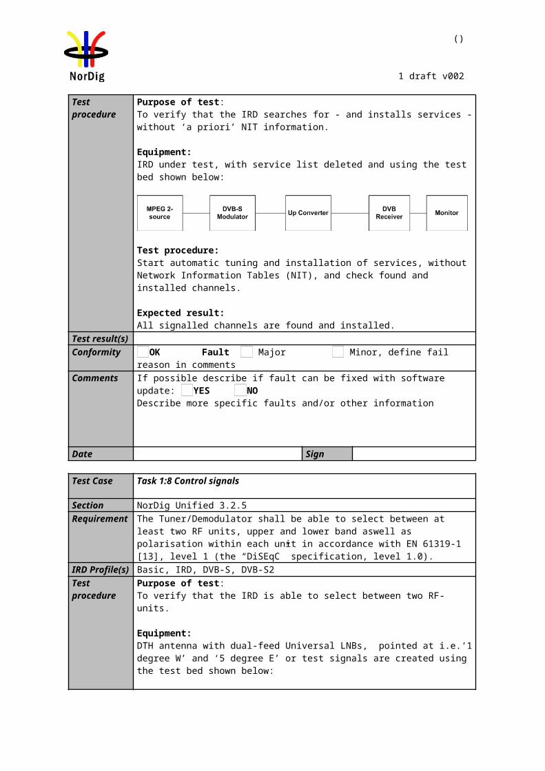
()
1 draft v002
Requirement The NIT scanning shall be able to find all the available channels on the network. During the first boot sequence or any time the IRD is re-installed, it will begin scanning for the Network Information Table using the following parameters:
Center frequencies: 114 MHz onwards in 8MHz steps until 858 MHz.Modulations: 64 QAM, 128 QAM and 256 QAMSymbol rates: 6.952 MSymbols/s (first attempt). If this rate does not result in reception, the following rates should be attempted: 6.950, 6.900, 6.875, 6.125 and 6.000 Msymbols/s.
Modulation mode: 16 QAM, 64QAM, 128QAM and 256QAM, where 128QAM and 16 QAM should be attempted last.
The scanning shall stop as soon as a valid Network Information Table (NIT_actual) is found. After that the NIT scanning procedure will continue according to information acquired from NIT.
IRD profile(s) Basic, IRD, DVB-CTest procedure Equipment:
Use the CATV network. The NIT shall describe all the digital channels.
Test procedure:1. Generate a cable TV signal with following parameters:
a) MUX1: Frequency 842 MHz, 256 QAM, Symbol Rate 6.000 MSymbols/sb) MUX 2: Frequency 858 MHz, 64 QAM, Symbol Rate 6.952 MSymbols/s
2. Make a new installation of the IRD.
3. Verify that the channel search is implemented according specification and finds all channels.
Expected result:
All digital channels in the network shall be found and the search is implemented according specification.
Test result(s)Conformity OK Fault Major Minor, define fail reason in commentsComments If possible describe if fault can be fixed with software update: YES NO
Describe more specific faults and/or other information
Date Sign
Test Case Task 2:9 Tuning/Scanning procedure (Manual scan)
Section NorDig Unified 3.3.4Requirement The receiver shall also offer manual scanning feature, where different scanning
parameters may be used.
IRD profile(s) Basic, IRD, DVB-C
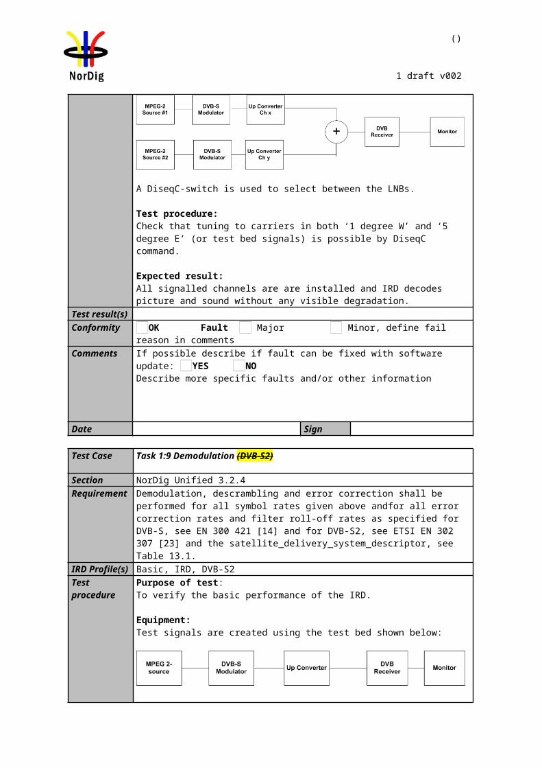
()
1 draft v002
Test procedure Equipment:Use the ordinary CATV network.
Test procedure:Make a new installation of the IRD by using manual scanning. Install a couple of multiplexes one by one using manual scanning
Expected result: All digital channels in the selected multiplexes are added to the channel list.
Test result(s)Conformity OK Fault Major Minor, define fail reason in commentsComments If possible describe if fault can be fixed with software update: YES NO
Describe more specific faults and/or other information
Date Sign
Test Case Task 2:10 Tuning/Scanning procedure (Original_network_id, transport_stream_id and service_id triplet support)
Section NorDig Unified 3.3.4Requirement
In the case where two transmitters transmit unique services which share the same service_id but the triplet on_id/ts_id/s_id is different. Then these services must be recognized as separate services and shall be added to the channel list accordingly.
IRD profile(s) Basic, IRD, DVB-CTest procedure Equipment:
MUX 1
MUX 2
Exciter 1
Exciter 2 Combiner STB
TS Source 2
TS Source 1
SI management system
Service1 Service2 FrequencyMUX1TS_id 1ON_id 1
SID 1100S_name Test11PMT PID 1100V PID 1109A PID 1108LCN 1
SID 1200S_name Test12PMT PID 1200V PID 1209A PID 1208LCN 3
. Can be chosen depending of the distribution media.
MUX2TS_id 2ON_id 1
SID 1100S_name Test21PMT PID 2100V PID 2109A PID 2108LCN 2
Can be chosen depending of the distribution media. Not same as for Exciter 1
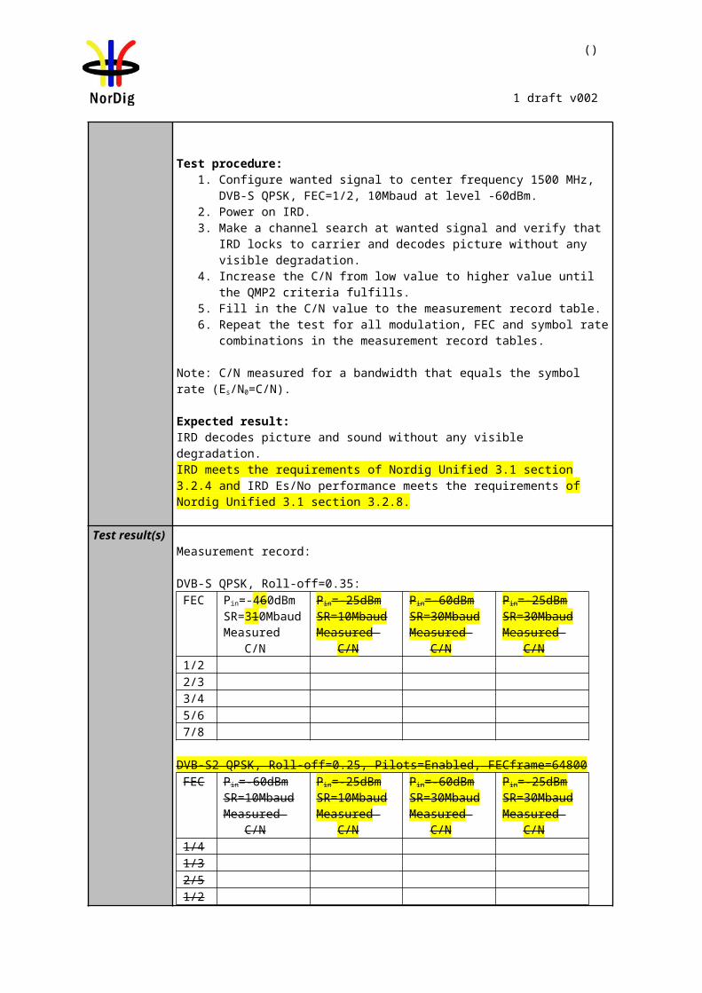
Digital Video generator
IRD Under test
Multiplexer Digital TV test transmitter
()
1 draft v002
Test procedure:Make a new installation of the box with automatic scan selected.
Expected result: All digital channels in the network shall be found in following order:
LCN Service1. Test112. Test213. Test12
Test result(s)Conformity OK Fault Major Minor, define fail reason in commentsComments If possible describe if fault can be fixed with software update: YES NO
Describe more specific faults and/or other information
Date Sign
Task 2:11 Tuning/Scanning procedure – Network default values
Section NorDig Unified 3.3.4Requirement It shall be possible to set and store specific network default values for search of digital
carriers, as required for the targeted network(s). The values shall be set either manually via the user interface, or as part of the stored default values in the NorDig IRD.
The network default values shall for each stored network id include:o Network id
o Frequency (ies) and modulation mode(s) for carriers that carry service information about actual and other transport streams, see section 13.2.2 (NorDig Unified)
o Symbol rate(s) for the specified carrier(s).
IRD profile(s) Basic, IRD, DVB-CTest procedure Purpose of test:
To verify that IRD supports network default values
Equipment:
Test procedure:Verify that the network defauld values can be set and are used to make the NIT based scan
Expected results:
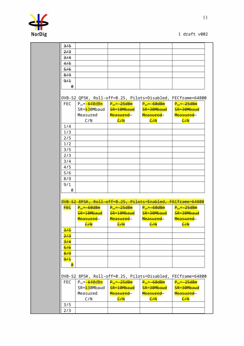
Digital Video generator
IRD Under test
Multiplexer Digital TV test transmitter
()
1 draft v002
The IRD has the network default values and they are used for NIT based scanning.
Test result(s)Conformity OK Fault Major Minor, define fail reason in commentsComments If possible describe if fault can be fixed with software update: YES NO
Describe more specific faults and/or other information
Date Sign
Task 2:12 Tuning/Scanning procedure – Factory default values
Section NorDig Unified 3.3.4Requirement In case there are no stored data for the selected network, the stored factory default
values shall be used for the initial search (Step 1 above). In case these default values do not result in reception of a carrier, a full search, covering all frequencies, modulation modes and symbol rates shall be performed (Step 2).The NorDig IRD shall as a minimum store a factory default value set, with the following data:
Carrier frequencies: 114MHz + n x 8MHz, where n is an integer in the range 0 to 93, see Table 3.3.
Modulation mode: 16 QAM, 64QAM, 128QAM and 256QAM, where 128QAM and 16 QAM should be attempted last.
Symbol rate: 6.952 MSymbols/s (first attempt). If this rate does not result in reception, the following rates should be attempted: 6.950, 6.900, 6.875, 6.125 (1) and 6.000 (1) Msymbols/s.
IRD profile(s) Basic, IRD, DVB-CTest procedure Purpose of test:
To verify that IRD supports factory default values
Equipment:
Test procedure:Verify that the factory defauld values are stored and are used to make the NIT based scan
Expected results:The IRD has the factory default values and they are used for NIT based scanning.
Test result(s)Conformity OK Fault Major Minor, define fail reason in commentsComments If possible describe if fault can be fixed with software update: YES NO
Describe more specific faults and/or other information
Date Sign
Task 2:13 Total input power
Section NorDig Unified 3.3.2.1Requirement The NorDig IRD shall operate with input network and channel RF characteristics as
specified in Table 3.3
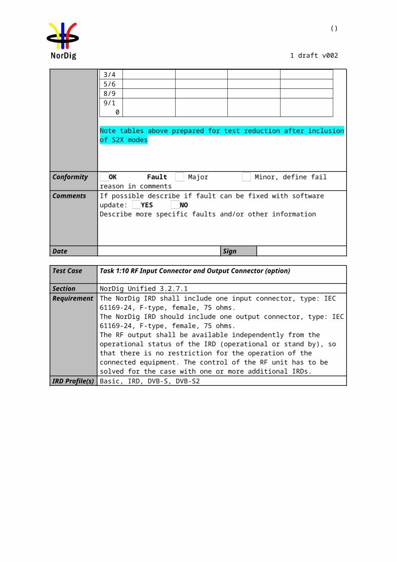
Digital Video generator(s)
IRD Under test
Multiplexer(s) Digital TV test transmitter(s)
()
1 draft v002
Total Input Power (80-862 MHz): Digital & analogue <93 dBµV at 75 Ohms
IRD profile(s) Basic, IRD, DVB-CTest procedure Purpose of test:
To verify that IRD can operate with required total input power
Equipment:IRD Under test and test signal generator environment
Test procedure:
1. Configure wanted signal to center frequency 666 MHz, 256 QAM, SR 6.952 Msymb/s at level 77 dBµV
2. Configure interference signal to center frequencies n-1 (658MHz) and n+1 (674 MHz), 256QAM, SR 6.952 Msymb/sat level 77 dBµV
3. Configure interference signal to center frequencies n-2(650MHz) and n+2(682MHz) , 256QAM, SR 6.952 Msymb/sat level 82 dBµV
4. Power on IRD5. Make a channel search at wanted signal and verify that IRD locks to carrier,
finds all channels and decodes picture without any visible degradation.6. Use quality measurement procedure 2 (QMP2).
Expected results:The IRDlocks to carrier and decodes picture without any visible degradation with required total power
Test result(s)Conformity OK Fault Major Minor, define fail reason in commentsComments If possible describe if fault can be fixed with software update: YES NO
Describe more specific faults and/or other information
Date Sign
Task 2:14 RF Performance - C/N for Reference BER
Section NorDig Unified 3.3.5.3Requirement The NorDig IRD shall operate with input network and channel RF characteristics as
specified in Table 3.4 in NorDig Unified specificficication [1]IRD profile(s) Basic, IRD, DVB-CTest procedure Purpose of test:
To check that the internal BER value measured by the receiver to reference BER value in a function of C/N on Gaussian channel is correct.
Equipment:
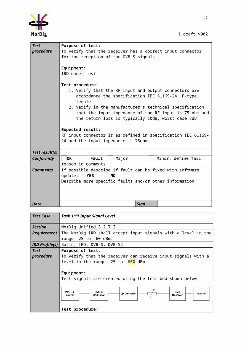
()
1 draft v002
Test procedure:
1. Setup the instruments.2. Use frequency 666 MHz and mode 256QAM, SR 6.952 Msymb/s. Set the RF
input level to 47dBµV.3. Use the quality measurement procedure 2.4. Adjust the required C/N that it corresponds BER 2E-4 after Viterbi. 5. Repeat test with all values in the measurement record table below. For
modulations 128QAM, 64QAM and 16QAM use SR 6.952 Msymb/s.
Expected result:The resulted C/N shall be lower than the required C/N for quality level BER 2E-4 after Viterbi in all tests in measurement record.
Test result(s) Measurement record:
QAM:
Level/dBµV
Required C/N (Es/No):
Result C/N
25654 32.0 dB77 32.0 dB47 35.0 dB53 35.0 dB
128 47 29.0 dB64 43 26.0 dB16 47 20.0 dB
Conformity OK Fault Major Minor, define fail reason in commentsComments If possible describe if fault can be fixed with software update: YES NO
Describe more specific faults and/or other information
Date Sign
Task 2:15 RF Performace - C/N with echo
Section NorDig Unified 3.3.5.4Requirement The NorDig IRD shall perform as specified in Table 3.43, plus an allowance of 1 dB
when an echo is applied in accordance to the template in Figure 3.1.IRD profile(s) Basic, IRD, DVB-C
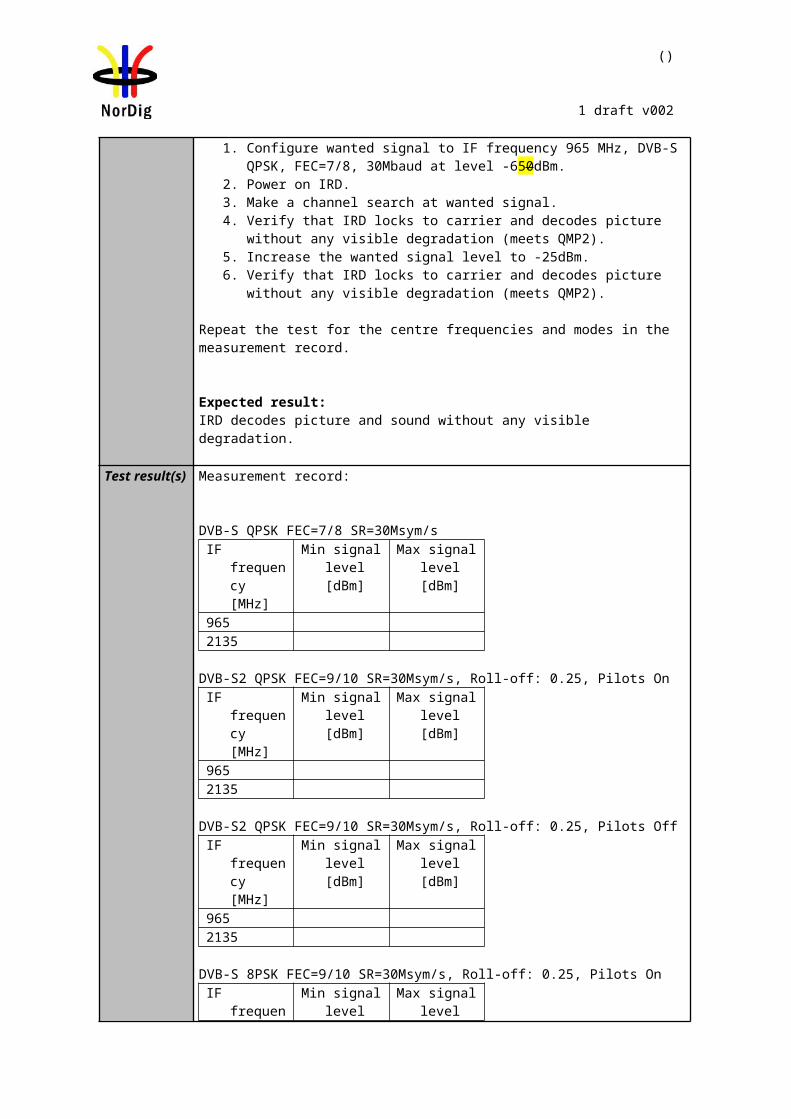
()
1 draft v002
Test procedure Purpose of test:To verify the required C/N when echoes are present.
Equipment:
Test procedure:
1. Set up the test instruments2. Use the following settings {256 QAM, SR=6.952, 666 Mhz, delay 0 ns}3. Measure the input level to the attenuator. 4. Determine the attenuation of the attenuator and the cables.5. Calculate the receiver input signal level and set it to 54dBµV.6. Use the value for the required C/N+1 dB specified in table 3.4 in NorDig
Unified specification [1].7. Do the channel search.8. Increase the C/N from low value to higher value until the quality measurement
procedure 2 fulfils.9. Fill in the measured value in dB in the measurement record. 10. Repeat the test for the rest of the modes and delaysdefined in the measurement
record.
Expected result:The measured C/N shall be within required C/N + 1 dB.
()
1 draft v002
Test result(s)
Echo / Mode, Level16-QAM
64-QAM
Att. [dB] Delay [ns] 47 dBµV 43 dBµV6.0 06.6 407.7 5013.4 10019.0 15024.7 20030.3 25033.7 28036.0 30036.0 350
Echo / Mode, Level128-QAM
Att. [dB] Delay [ns] 47 dBµV9.0 09.6 4010.7 5016.4 10022.0 15027.7 20033.3 25036.7 28039.0 30039.0 350
Echo / Mode, Level256-QAM
Att. [dB] Delay [ns] 47 dBµV 54 dBµV12.0 012.6 4013.7 5019.4 10025.0 15030.7 20036.3 25039.7 28042.0 30042.0 350
Conformity OK Fault Major Minor, define fail reason in commentsComments If possible describe if fault can be fixed with software update: YES NO
Describe more specific faults and/or other information
Date Sign
Test Case Task 2:16 Performance Data: Noise figure
Section NorDig Unified 3.3.5.1Requirement The performance data below shall be satisfied:
Noise figure: less than 8 dB.
IRD profile(s) Basic, IRD, DVB-C
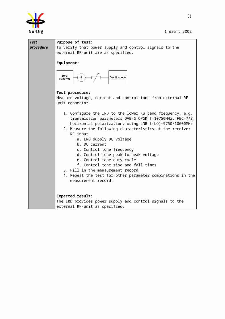
()
1 draft v002
Test procedurePurpose of test:To verify the receiver noise figure performance.
Equipment:
Test procedure:
1. Set up the test instruments2. Use the following settings {256 QAM, SR=6.952 , roll-off 0.15}.3. Use the channel K45 (666 MHz)4. Measure the input level to the attenuator. 5. Determine the attenuation of the attenuator and the cables.6. Calculate the receiver input signal level and set it to 59 dBµV.7. Do the channel search.8. Increase the C/N from low value to higher value until the quality measurement
procedure 2 fulfils.9. Fill in the measured C/N value in dB in the measurement record. 10. Shutdown added noise.11. Decrease the signal input level to such a level that receiver is not able to
provide picture. 12. Increase the signal input level to receiver until the quality measurement
procedure 2 fulfills. 13. Fill in the sensitivity Pmin value in dBµV in measurement record.14. Repeat the test for the rest of the frequencies defined in the measurement
record.15. Calculate the NF using formula: NF[dB] = Pmin - C/N - 3.8 dBµV
Expected result:Noise figure is lower than 8dB.
Test result(s) Measurement record:
f [MHz]114 210 282 386 474 666 858
C/N [dB]Pmin [dBµV]NF [dB]
Conformity OK Fault Major Minor, define fail reason in comments
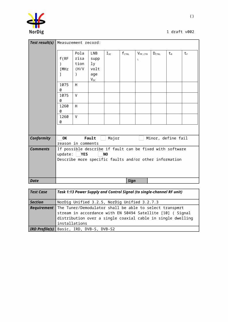
Digital Video generator(s)
IRD Under test
Multiplexer(s) Digital TV test transmitter(s)
()
1 draft v002
Comments If possible describe if fault can be fixed with software update: YES NODescribe more specific faults and/or other information
Date Sign
Task 2:17 RF Performance - Image Channel
Section NorDig Unified 3.3.5.5RequirementIRD profile(s) Basic, IRD, DVB-CTest procedure Purpose of test:
To verify that IRD can operate with required image channels
Equipment:IRD Under test and test signal generator environment
Test procedure:
1. Configure wanted signal to center frequency 666 MHz, 256 QAM, SR 6.952 at level 47 dBµV
2. Configure interference signal to center frequencyn-9 (594 MHz), 256 QAM, SR 6.952 Msym/s at level 57 dBµV
3. Power on IRD4. Make a channel search at wanted signal and verify that IRD locks to carrier,
finds all channels and decodes picture without any visible degradation.5. Apply Gaussian noise to the wanted signal.6. Increase the C/N from low value to higher value until the quality measurement
procedure 2 (QMP2) fulfills.7. Fill in the measured C/N value in dB in the measurement record.8. Repeat the test procedure for all DVB-C modes in the measurement recordfor
both interference signal frequencies (n-9 and n+9).
Expected results:The IRD locks to carrier and decodes picture without any visible degradation. The measured C/N shall be within required C/N + allowances.
Test result(s) Measurement record:
Image channel (n-9): 594 MHzWanted signal [dBμV]
Image channel (n-9) [dBμV]
16 QAM 128 QAM 256 QAM
47 4777 7747 5772 82
Wanted signal [dBμV]
Image channel (n-9) [dBμV] 64 QAM
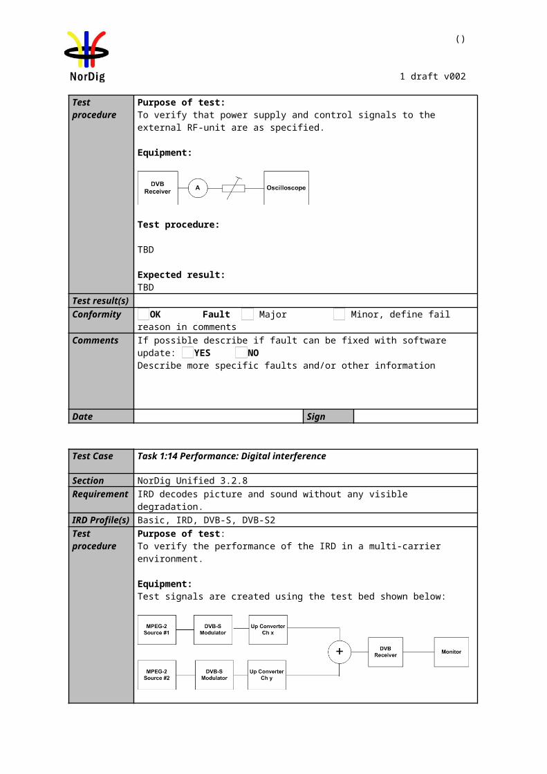
Digital Video generator(s)
IRD Under test
Multiplexer(s) Digital TV test transmitter(s)
()
1 draft v002
43 4373 7343 5372 82
Image channel (n+9): 738 MHzWanted signal [dBμV]
Image channel (n+9) [dBμV]
16 QAM 128 QAM 256 QAM
47 4777 7747 5772 82
Wanted signal [dBμV]
Image channel (n+9) [dBμV]
64 QAM
43 4373 7343 5372 82
Conformity OK Fault Major Minor, define fail reason in commentsComments If possible describe if fault can be fixed with software update: YES NO
Describe more specific faults and/or other information
Date Sign
Task 2:18 RF Performance – Digital Adjacent Channel
Section NorDig Unified 3.3.5.6 and 3.3.5.7Requirement The NorDig IRD shall perform as specified in section 3.3.5.3 with
a) Digital signals at 0dBc in the adjacent channels.b) Analogue signals at +10dB in the adjacent channels
The NorDig IRD shall perform as specified in section 3.3.5.3, plus an allowance of 0.2 dB with digital signals at +10dBc in adjacent channels.
IRD profile(s) Basic, IRD, DVB-CTest procedure Purpose of test:
To verify that IRD can operate with required adjacent channels
Equipment:IRD Under test and test signal generator environment
Test procedure:
1. Configure wanted signal to center frequency 666 MHz, 256 QAM, SR 6.952 Msym/s at level 47 dBµV
2. Configure interference signal to center frequencies n+1 (674 MHz) and n-1
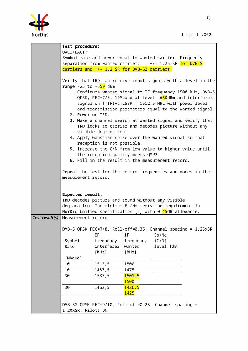
()
1 draft v002
( 658 MHz), 256 QAM, SR 6.952 Msym/s at level 47 dBµV.3. Power on IRD4. Make a channel search at wanted signal and verify that IRD locks to carrier,
finds all channels and decodes picture without any visible degradation 5. Apply Gaussian noise to the wanted signal.6. Increase the C/N from low value to higher value until the quality measurement
procedure 2 (QMP2) fulfills.7. Fill in the measured C/N value in dB in the measurement record.8. Repeat the test for the DVB-C modes and signal levels in the measurement
record.
Expected results:The IRD locks to carrier and decodes picture without any visible degradation.The measured C/N shall be within required C/N + allowances.
Test result(s)Wanted signal [dBμV]
Adjacent channels (n-1, n+1) [dBμV]
16 QAM 128 QAM 256 QAM
47 4777 7747 5772 82
Wanted signal [dBμV]
Adjacent channels (n-1, n+1) [dBμV]
64 QAM
43 4373 7343 5372 82
Conformity OK Fault Major Minor, define fail reason in commentsComments If possible describe if fault can be fixed with software update: YES NO
Describe more specific faults and/or other information
Date Sign
Task 2:19 RF Performance – Analog Adjacent Channel
Section NorDig Unified 3.3.5.6 and 3.3.5.7Requirement The NorDig IRD shall perform as specified in section 3.3.5.3 with
c) Digital signals at 0dBc in the adjacent channels.d) Analogue signals at +10dB in the adjacent channels
The NorDig IRD shall perform as specified in section 3.3.5.3, plus an allowance of 0.2 dB with digital signals at +10dBc in adjacent channels.
IRD profile(s) Basic, IRD, DVB-C
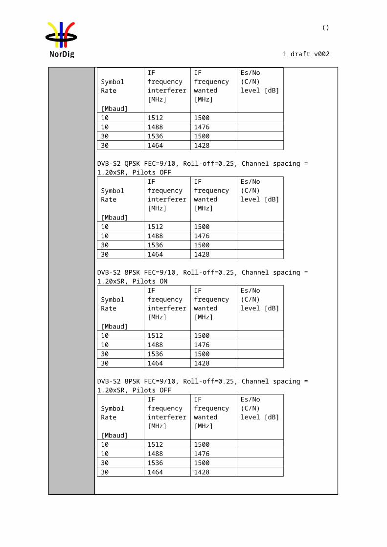
()
1 draft v002
Test procedure Purpose of test:To verify that IRD can operate with required adjacent channels
Test procedure:
1. Set up the test instruments2. Use the following PAL signal: Colour bar 75%3. Insert 12 lines of Teletext.4. Modulate the FM sound carrier with 1kHz ton to deviation of 50 kHz.5. Verify that the signal levels of the DVB-C signal and the analogue signal are
correct e.g. by using the spectrum analyser.6. Adjust the level of the FM carrier to -13 dB relative to the vision carrier7. Adjust the level from NICAM modulator to -20 dB relative to the vision
carrier.8. Use the following DVB-C mode: { 256 QAM, SR=6.952 @ 77 dBµV}.9. Set the upconverter (wanted) for DVB-C carrier to 666.0MHz 10. Set the upconverters (interference) for analog TV carrier to frequency n-1
(658MHz) and n+1 (674 MHz) 11. Set the receiver input levels for the analog TV signals to 77 dBµV.12. Apply Gaussian noise to the wanted signal.13. Increase the C/N from low value to higher value until the quality measurement
procedure 2 (QMP2) fulfills.14. Fill in the measured C/N value in dB in the measurement record.15. Repeat the test for the DVB-C modes and signal levels in the measurement
record.
Expected result:The measured C/N shall be within required C/N + allowances.

()
1 draft v002
Test result(s) Wanted signal [dBμV]
Adjacent channels (n-1, n+1) [dBμV]
16 QAM 128 QAM 256 QAM
47 4777 7747 5772 82
Wanted signal [dBμV]
Adjacent channels (n-1, n+1) [dBμV]
64 QAM
43 4373 7343 5372 82
Conformity OK Fault Major Minor, define fail reason in commentsComments If possible describe if fault can be fixed with software update: YES NO
Describe more specific faults and/or other information
Date Sign
Task 2:20 LO leakage
Section NorDig Unified 3.3.6.1Requirement The LO leakage conducted emission (including LO and spurious) from the NorDig IRD,
measured at the antenna input connector shall be 46dBμV over the range 65 to 862MHz
IRD profile(s) Basic, IRD, DVB-CTest procedure Purpose of test:
To verify that IRD fulfils the LO leakage requirements
Equipment:IRD Under test and spectrum analyzer
Test procedure:1. Verify that LO leakage is within requirements
Expected results:The IRD fulfils the LO leakage requirements,
Test result(s)Conformity OK Fault Major Minor, define fail reason in commentsComments If possible describe if fault can be fixed with software update: YES NO
Describe more specific faults and/or other information
Date Sign
Task 2:21 Spurious emission
Section NorDig Unified 3.3.6.2
()
1 draft v002
Requirement The spurious emission from the NorDig IRD to the network, as measured at the antenna input connector, shall be less than 34 dBμV over the range 5MHz to 65MHz and less than 30 dB μV over 65 to 862 MHz.
Generally, spurious emission should not affect the sensitivity of the receiver.
IRD profile(s) Basic, IRD, DVB-CTest procedure Purpose of test:
To verify that IRD fulfils the sperious emission requirements
Equipment:IRD Under test and spectrum analyzer
Test procedure:1. Verify that spurious emission is within requirementsor verify the values from
manufactures statement.
Expected results:The IRD fulfils the speurious emission requirements,
Test result(s)Conformity OK Fault Major Minor, define fail reason in commentsComments If possible describe if fault can be fixed with software update: YES NO
Describe more specific faults and/or other information
Date Sign
Task 2:22 Radiation
Section NorDig Unified 3.3.6.3Requirement The radiation from the NorDig IRD shall comply with EN 55013IRD profile(s) Basic, IRD, DVB-CTest procedure Purpose of test:
To verify that IRD fulfils the radiation requirements
Equipment:IRD Under test
Test procedure:Statement from the manufacture shall be included.
Expected results:The IRD fulfils the radiation requirements,
Test result(s)Conformity OK Fault Major Minor, define fail reason in commentsComments If possible describe if fault can be fixed with software update: YES NO
Describe more specific faults and/or other information
Date Sign
()
1 draft v002
2.3 Task 3: Terrestrial Tuner and Demodulator
2.3.1 Test equipment summaryTo configure the minimum test setups described in these test procedures the following functionalities are needed:
Video and audio source (MPEG-2)Re-multiplexersBroadband Fading simulator Noise generator DVB-T/T2 Exciter (DVB-T/T2 modulator and up-converter)Analog TV RF Exciter with PAL, NICAM and teletext generator.
DVB-T or DVB-T2 receiver with RF inputTransport stream analyzersPower meter with thermo coupled 50ohm and 75ohm power sensorVideo monitor
Note! The needed instruments may vary depending on the used system and can be purchased from many vendors in a compact all-in-one units. Different test setups are defined in every test case. However, most of the tests can done using one general test setup.
2.3.2 QEF Quality Measurement Methods
The quality limit in this specification is defined as Quasi Error Free (QEF) reception, where QEF means less than one uncorrected error event per hour. The definition of QEF corresponds to BER of 10-11 in the TS data at input of the MPEG-2 demultiplexer. In practice, it takes long time to measure such a low BER at TS data level. Therefore, the reception quality can be evaluated either indirectly by
measuring the BER after Viterbi in DVB-T system, or measuring the BER after LDPC in DVB-T2 system, or
subjectively inspecting the video screen for a certain period of time and looking for errors in the decoded video.
Direct measurements on the TS data packets are the preferred measurement method, but if this is not possible or acceptable for some reason, the indirect measurements can be used. The indirect measurement methods, which can be used, are objective BER measurements described above or subjective quality measurement.
In the indirect objective method in the DVB-T system, the BER of 2*10-4 after Viterbi decoder is considered to correspond to an approximation of QEF reception quality for Gaussian type of channels. But for channels interfered by impulse like interference i.e. PAL signals or internal interference, the average BER of 2*10-4 after Viterbi decoder is not valid due to the fact that the RS decoder is not able to correct the burst of errorneous bytes caused by impulse like interference. Therefore, for impulse like interfered channels, the quality measurements shall be done by using the BER of 10-11 measurement method at the TS level at MPEG-2 demultiplexer input or by using the subjective measurement method.
In the indirect objective method in the DVB-T2 system the BER of 10-7 after LDPC decoder is considered to correspond to an approximation of QEF reception quality for Gaussian type of channels.
In the indirect subjective measurement method the certain period of time of error free video decoding is considered to corresponds to a good reception quality. The specified video test sequence can be any containing movement everywhere, in order to minimise the number of errors not being observed due to error concealment techniques in the receiver. Such a relevant video sequences are e.g. ‘Mobile and calendar’ and ‘Zoneplate’.
()
1 draft v002
The result of the indirect quality measurements may differ. Therefore, the method that shall be used is specified in every test case. However, the reception quality shall be verified by using the subjective measurement method for every test case. The measurement methods (procedures) are defined below.
Direct objective quality measurement procedure in DVB-T and DVB-T2 systems
The measurement is performed doing measurements at the transport stream data level. The measurement configuration parameters are chosen like that there is less than one uncorrected error event per hour. This requirement corresponds to BER value 10-11 at the TS data level at the input of the MPEG-2 demultiplexer. In addition to the BER measurement, the reception quality shall be verified subjectively.
The performance in every test case can be evaluated by using the direct quality measurement procedure.
Indirect subjective quality measurement procedure 1 (QMP1) in DVB-T and DVB-T2 systems
The subjective measurement is performed during 15 seconds. During this time the decoded video shall be error free. In a case of an error in decoded video, the change to the measurement configuration parameters shall be done. The change of the measurement configuration parameters shall result to an error free decoding of the video where the minimum time between consecutive subjective errors is 15 seconds. Otherwise, the change of the measurement configuration parameters is repeated until an error free decoding of video is reached at least 15 seconds.
Indirect objective or subjective quality measurement procedure 2 (QMP2) in DVB-T system
The measurement can be performed either by using
5. the embedded BER after Viterbi measurement provided by the receiver ,or 6. watching the decoded video for 60 seconds.
If the BER after Viterbi measurement is chosen, the value for the approximation of the QEF reception is considered to correspond to the integrated BER after Viterbi decoder value 2*10-4 .The integrated BER after Viterbi measurement value 2*10-4 shall be verified that it corresponds an error free video decoding. In case of higher BER after Viterbi value than 2*10-4 , the change to the measurement configuration parameters shall be done. The change of the measurement configuration parameters shall result to a BER after Viterbi which is lower than or equal to 2*10-4 , Otherwise, the change of the measurement configuration parameters is repeated until a BER after Viterbi value lower than or equal to 2*10-4 is achieved.
If the 60 seconds error free decoded video is chosen, during this time the decoded video shall be error free. In a case of an error in decoded video, the change to the measurement configuration parameters shall be done. The change of the measurement configuration parameters shall result to an error free decoding of the video where the minimum time between consecutive subjective errors is 60 seconds. Otherwise, the change of the measurement configuration parameters is repeated until an error free decoding of video is achieved at least 60 seconds.
The corresponding measurement value for profile and DVB-T mode shall be achieved from tables below.
()
1 draft v002
C/N performance (dB)Modulation Code rate Profile 1 :
GaussianProfile 2 : 0 dB echo
“60 sec error free
video”
BER 2E-4 after Viterbi
“60 sec error free
video”
BER 2E-4 after Viterbi
QPSK 1/2 3.8 5.1 7.7 8.8QPSK 2/3 5.6 6.9 11.9 13.7QPSK 3/4 6.6 7.9 14.1 17.4QPSK 5/6 7.6 8.9 - -QPSK 7/8 8.4 9.7 - -
16-QAM 1/2 9.5 10.8 12.0 13.316-QAM 2/3 11.8 13.1 16.3 17.916-QAM 3/4 13.3 14.6 19.0 22.116-QAM 5/6 14.3 15.6 - -16-QAM 7/8 14.7 16.0 - -64-QAM 1/2 15.2 16.5 17.7 19.064-QAM 2/3 17.4 18.7 21.8 23.264-QAM 3/4 18.9 20.2 24.8 27.664-QAM 5/6 20.3 21.6 - -64-QAM 7/8 21.2 22.5 - -
Table 2.3 Maximum required C/N for “60 seconds error free video” and BER 2E-4 after Viterbi (with 1/4 guard interval and FFT size 8K) for profiles 1 and 2
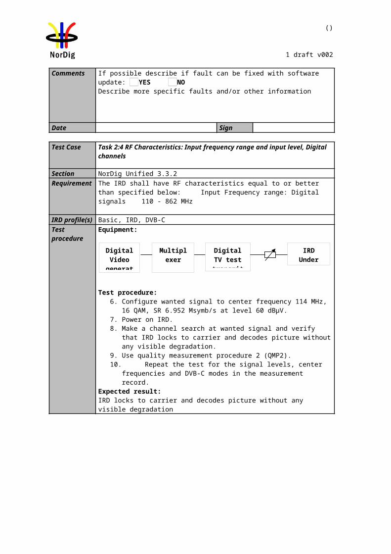
()
1 draft v002
Minimum input level (dBm)Profile 1: Gaussian
Profile 2:0 dB echo
Frequency bandVHF
Band IIIVHF
S Band I & II
VHFS Band I & II and
UHFS Band III
UHFBand IV&V
VHFBand III
UHFBand IV&V
7 MHz signal 7 MHz signal 8 MHz signal 8 MHz signal 7 MHz signal 8 MHz signal
ModulationCode Rate
“60 secerror free
video”
BER2E-4after
Viterbi
“60 secerrorfree
video”
BER2E-4after
Viterbi
“60 secerror free
video”
BER2E-4after
Viterbi
“60 secerror free
video”
BER2E-4after
Viterbi
“60 secerror free
video”
BER2E-4after
Viterbi
“60 secerror free
video”
BER2E-4after
Viterbi”QPSK 1/2 -94.9 -93.6 -91.9 -90.6 -91.4 -90.1 -94.4 -93.1 -91.1 -89.9 -90.6 -89.4
QPSK 2/3 -93.1 -91.8 -90.1 -88.8 -89.6 -88.3 -92.6 -91.3 -86.8 -85.0 -86.3 -84.5
QPSK 3/4 -92.1 -90.8 -89.1 -87.8 -88.6 -87.3 -91.6 -90.3 -84.6 -81.3 -84.1 -80.8
QPSK 5/6 -91.1 -89.8 -88.1 -86.8 -87.6 -86.3 -90.6 -89.3 - - - -
QPSK 7/8 -90.3 -89.0 -87.3 -86.0 -86.8 -85.5 -89.8 -88.5 - - - -
16-QAM 1/2 -89.2 -87.9 -86.2 -84.9 -85.7 -84.4 -88.7 -87.4 -86.6 -85.4 -86.1 -84.9
16-QAM 2/3 -86.9 -85.6 -83.9 -82.6 -83.4 -82.1 -86.4 -85.1 -82.4 -80.8 -81.9 -80.3
16-QAM 3/4 -85.4 -84.1 -82.4 -81.1 -81.9 -80.6 -84.9 -83.6 -79.7 -76.6 -79.2 -76.1
16-QAM 5/6 -84.4 -83.1 -81.4 -80.1 -80.9 -79.6 -83.9 -82.6 - - - -
16-QAM 7/8 -84.0 -82.7 -81.0 -79.7 -80.5 -79.2 -83.5 -82.2 - - - -
64-QAM 1/2 -83.5 -82.2 -80.5 -79.2 -80.0 -78.7 -83.0 -81.7 -80.9 -79.7 -80.4 -79.2
64-QAM 2/3 -81.3 -80.0 -78.3 -77.0 -77.8 -76.5 -80.8 -79.5 -76.9 -75.5 -76.4 -75.0
64-QAM 3/4 -79.8 -78.5 -76.8 -75.5 -76.3 -75.0 -79.3 -78.0 -73.9 -71.1 -73.4 -70.6
64-QAM 5/6 -78.4 -77.1 -75.4 -74.1 -74.9 -73.6 -77.9 -76.6 - - - -
64-QAM 7/8 -77.5 -76.2 -74.5 -73.2 -74.0 -72.7 -77.0 -75.7 - - - -
Table 2.4 Minimum signal input levels (Pmin) for “60 seconds error free video” and BER 2E-4 after Viterbi (with 1/4 guard interval and FFT size 8K) for profiles 1 and 2.
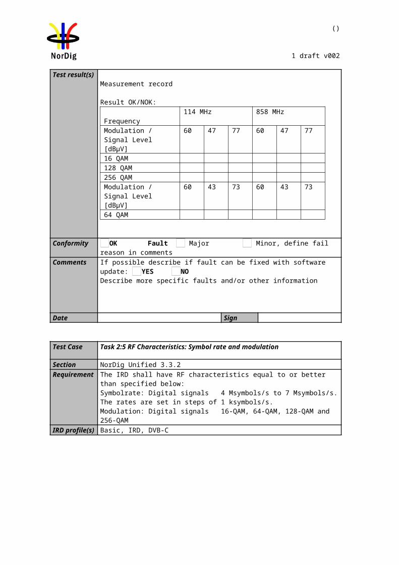
()
1 draft v002
Indirect objective or subjective quality measurement procedure 2 (QMP2) in DVB-T2 system
The measurement can be performed either by using
3. the embedded BER after LDPC measurement provided by the receiver, or 4. watching the decoded video for 30 seconds.
If the BER after LDPC measurement is chosen, the value for the approximation of the QEF reception is considered to correspond to the integrated BER after LDPC decoder value 10-7. In case of higher BER after LDPC value than 10-7 , the change to the measurement configuration parameters shall be done. The change of the measurement configuration parameters shall result to a BER after LDPC which is lower than or equal to 10-7, Otherwise, the change of the measurement configuration parameters is repeated until the BER after LDPC value lower than or equal to 10-7 is achieved. That reception shall be verified that it corresponds an error free video decoding.
If the 30 seconds error free decoded video is chosen, during this time the decoded video shall be error free. In a case of an error in decoded video, the change to the measurement configuration parameters shall be done. The change of the measurement configuration parameters shall result to an error free decoding of the video where the minimum time between consecutive subjective errors is 30 seconds. Otherwise, the change of the measurement configuration parameters is repeated until an error free decoding of video is achieved at least 30 seconds.
Due to the nature of the DVB-T2 system forward error correction schemes the difference for the 30 seconds error free video and BER 10-7 after LDPC is very low. For practical testing the performance values are equal for both quality levels.
The corresponding measurement value for profile and DVB-T2 mode shall be achieved from tables below.
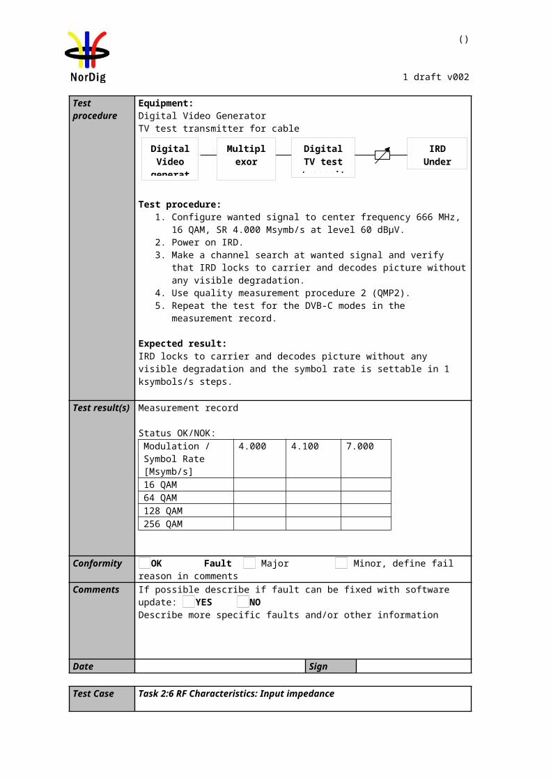
()
1 draft v002
C/N performance (dB) for PP2Modulation Code rate Profile 1 :
GaussianProfile 2 : 0 dB echo
“30 sec error free
video”
BER 1E-7 after LDPC
“30 sec error free
video”
BER 1E-7 after LDPC
QPSK 1/2 3.5 3.5 5.2 5.2QPSK 3/5 4.7 4.7 6.8 6.8QPSK 2/3 5.6 5.6 8.4 8.4QPSK 3/4 6.6 6.6 9.8 9.8QPSK 4/5 7.2 7.2 - -QPSK 5/6 7.7 7.7 - -
16-QAM 1/2 8.7 8.7 10.9 10.916-QAM 3/5 10.1 10.1 12.7 12.716-QAM 2/3 11.4 11.4 14.3 14.316-QAM 3/4 12.5 12.5 16.3 16.316-QAM 4/5 13.3 13.3 - -16-QAM 5/6 13.8 13.8 - -64-QAM 1/2 13.0 13.0 16.0 16.064-QAM 3/5 14.8 14.8 18.0 18.064-QAM 2/3 16.2 16.2 19.7 19.764-QAM 3/4 17.7 17.7 22.0 22.064-QAM 4/5 18.7 18.7 - -64-QAM 5/6 19.4 19.4 - -256-QAM 1/2 17.0 17.0 20.6 20.6256-QAM 3/5 19.4 19.4 23.1 23.1256-QAM 2/3 20.8 20.8 25.1 25.1256-QAM 3/4 22.9 22.9 27.9 27.9256-QAM 4/5 24.3 24.3 - -256-QAM 5/6 25.1 25.1 - -
Table 2.5Maximum required C/N for “30 seconds error free video” and BER 1E-7 after LDPC for PP2 and for any allowed combination of guard interval, signal bandwidth, FFT size and carrier mode.
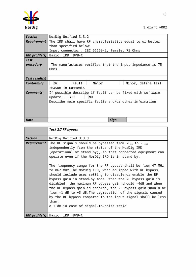
()
1 draft v002
C/N performance (dB) for PP4Modulation Code rate Profile 1 :
GaussianProfile 2 : 0 dB echo
“30 sec error free
video”
BER 1E-7 after LDPC
“30 sec error free
video”
BER 1E-7 after LDPC
QPSK 1/2 3.1 3.1 4.8 4.8QPSK 3/5 4.3 4.3 6.4 6.4QPSK 2/3 5.2 5.2 8.0 8.0QPSK 3/4 6.2 6.2 9.4 9.4QPSK 4/5 6.8 6.8 - -QPSK 5/6 7.3 7.3 - -
16-QAM 1/2 8.3 8.3 10.5 10.516-QAM 3/5 9.7 9.7 12.3 12.316-QAM 2/3 11.0 11.0 13.9 13.916-QAM 3/4 12.1 12.1 15.8 15.816-QAM 4/5 12.9 12.9 - -16-QAM 5/6 13.4 13.4 - -64-QAM 1/2 12.6 12.6 15.5 15.564-QAM 3/5 14.4 14.4 17.6 17.664-QAM 2/3 15.7 15.7 19.2 19.264-QAM 3/4 17.3 17.3 21.5 21.564-QAM 4/5 18.3 18.3 - -64-QAM 5/6 18.9 18.9 - -256-QAM 1/2 16.5 16.5 20.2 20.2256-QAM 3/5 18.9 18.9 22.6 22.6256-QAM 2/3 20.4 20.4 24.6 24.6256-QAM 3/4 22.4 22.4 27.4 27.4256-QAM 4/5 23.8 23.8 - -256-QAM 5/6 24.6 24.6 - -
Table 2.6Maximum required C/N for “30 seconds error free video” and BER 1E-7 after LDPC for PP4 and for any allowed combination of guard interval, signal bandwidth, FFT size and carrier mode.
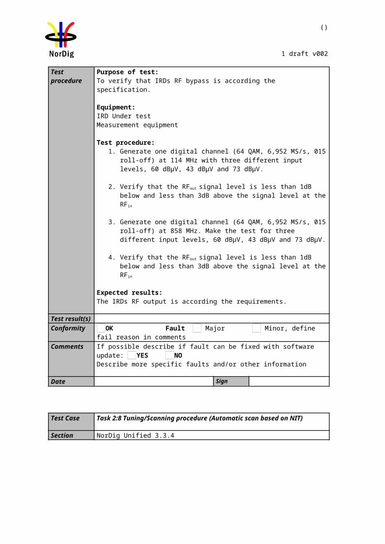
()
1 draft v002
C/N performance (dB) for PP6Modulation Code rate Profile 1 :
GaussianProfile 2 : 0 dB echo
“30 sec error free
video”
BER 1E-7 after LDPC
“30 sec error free
video”
BER 1E-7 after LDPC
QPSK 1/2 2.6 2.6 4.3 4.3QPSK 3/5 3.8 3.8 5.9 5.9QPSK 2/3 4.7 4.7 7.5 7.5QPSK 3/4 5.7 5.7 8.9 8.9QPSK 4/5 6.3 6.3 - -QPSK 5/6 6.8 6.8 - -
16-QAM 1/2 7.8 7.8 10.0 10.016-QAM 3/5 9.2 9.2 11.8 11.816-QAM 2/3 10.5 10.5 13.4 13.416-QAM 3/4 11.6 11.6 15.4 15.416-QAM 4/5 12.4 12.4 - -16-QAM 5/6 12.9 12.9 - -64-QAM 1/2 12.1 12.1 15.0 15.064-QAM 3/5 13.9 13.9 17.1 17.164-QAM 2/3 15.3 15.3 18.7 18.764-QAM 3/4 16.8 16.8 21.0 21.064-QAM 4/5 17.8 17.8 - -64-QAM 5/6 18.4 18.4 - -256-QAM 1/2 16.1 16.1 19.7 19.7256-QAM 3/5 18.4 18.4 22.1 22.1256-QAM 2/3 19.9 19.9 24.1 24.1256-QAM 3/4 21.9 21.9 26.8 26.8256-QAM 4/5 23.3 23.3 - -256-QAM 5/6 24.1 24.1 - -
Table 2.7Maximum required C/N for “30 seconds error free video” and BER 1E-7 after LDPC for PP6 and for any allowed combination of guard interval, signal bandwidth, FFT size and carrier mode.
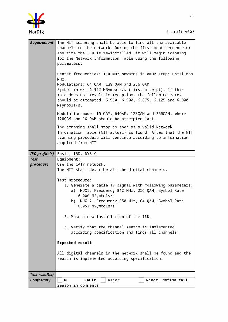
()
1 draft v002
C/N performance (dB) for PP7Modulation Code rate Profile 1 :
GaussianProfile 2 : 0 dB echo
“30 sec error free
video”
BER 1E-7 after LDPC
“30 sec error free
video”
BER 1E-7 after LDPC
QPSK 1/2 2.4 2.4 4.1 4.1QPSK 3/5 3.6 3.6 5.7 5.7QPSK 2/3 4.5 4.5 7.3 7.3QPSK 3/4 5.5 5.5 8.7 8.7QPSK 4/5 6.1 6.1 - -QPSK 5/6 6.6 6.6 - -
16-QAM 1/2 7.6 7.6 9.9 9.916-QAM 3/5 9.0 9.0 11.7 11.716-QAM 2/3 10.4 10.4 13.3 13.316-QAM 3/4 11.5 11.5 15.2 15.216-QAM 4/5 12.3 12.3 - -16-QAM 5/6 12.8 12.8 - -64-QAM 1/2 12.0 12.0 14.9 14.964-QAM 3/5 13.8 13.8 16.9 16.964-QAM 2/3 15.1 15.1 18.6 18.664-QAM 3/4 16.6 16.6 - -64-QAM 4/5 17.7 17.7 - -64-QAM 5/6 18.3 18.3 24.3 24.3256-QAM 1/2 15.9 15.9 19.5 19.5256-QAM 3/5 18.3 18.3 22.0 22.0256-QAM 2/3 19.7 19.7 23.9 23.9256-QAM 3/4 21.7 21.7 26.6 26.6256-QAM 4/5 23.2 23.2 - -256-QAM 5/6 23.9 23.9 - -
Table 2.8Maximum required C/N for “30 seconds error free video” and BER 1E-7 after LDPC for PP7 and for any allowed combination of guard interval, signal bandwidth, FFT size and carrier mode.
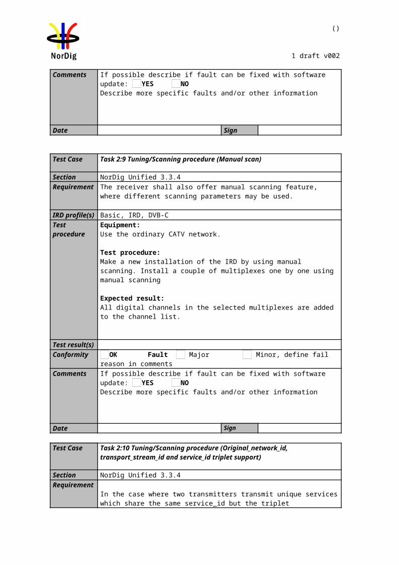
()
1 draft v002
Minimum input level (dBm) for PP2Profile 1: Gaussian
Profile 2:0 dB echo
Frequency bandVHF
Band IIIVHF
S Band I & II
VHFS Band I & II and
UHFS Band III
UHFBand IV&V
VHFBand III
UHFBand IV&V
1.7 MHz signal 7 MHz signal 7 MHz signal 8 MHz signal 8 MHz signal 1.7 MHz signal 7 MHz signal 8 MHz signal
ModulationCode Rate
“30 secerror free
video”
BER1E-7after
LDPC
“30 secerror free
video”
BER1E-7after
LDPC
“30 secerrorfree
video”
BER1E-7after
LDPC
“30 secerror free
video”
BER1E-7after
LDPC
“30 secerror free
video”
BER1E-7after
LDPC
“30 secerror free
video”
BER1E-7after
LDPC
“30 secerror free
video”
BER1E-7after
LDPC
“30 secerror free
video”
BER1E-7after
LDPCQPSK 1/2 -101.6 -101.6 -96.2 -96.2 -92.2 -92.2 -91.6 -91.6 -95.6 -95.6 -99.9 -99.9 -94.5 -94.5 -93.9 -93.9QPSK 3/5 -100.4 -100.4 -95.0 -95.0 -91.0 -91.0 -90.4 -90.4 -94.4 -94.4 -98.3 -98.3 -92.9 -92.9 -92.3 -92.3QPSK 2/3 -99.5 -99.5 -94.1 -94.1 -90.1 -90.1 -89.5 -89.5 -93.5 -93.5 -96.7 -96.7 -91.3 -91.3 -90.7 -90.7QPSK 3/4 -98.5 -98.5 -93.1 -93.1 -89.1 -89.1 -88.5 -88.5 -92.5 -92.5 -95.3 -95.3 -89.9 -89.9 -89.3 -89.3QPSK 4/5 -97.9 -97.9 -92.5 -92.5 -88.5 -88.5 -87.9 -87.9 -91.9 -91.9 -94.2 -94.2 -88.8 -88.8 -88.2 -88.2QPSK 5/6 -97.4 -97.4 -92.0 -92.0 -88.0 -88.0 -87.4 -87.4 -91.4 -91.4 -93.1 -93.1 -87.7 -87.7 -87.1 -87.1
16-QAM 1/2 -96.4 -96.4 -91.0 -91.0 -87.0 -87.0 -86.4 -86.4 -90.4 -90.4 -94.2 -94.2 -88.8 -88.8 -88.2 -88.216-QAM 3/5 -95.0 -95.0 -89.6 -89.6 -85.6 -85.6 -85.0 -85.0 -89.0 -89.0 -92.4 -92.4 -87.0 -87.0 -86.4 -86.416-QAM 2/3 -93.7 -93.7 -88.3 -88.3 -84.3 -84.3 -83.7 -83.7 -87.7 -87.7 -90.8 -90.8 -85.4 -85.4 -84.8 -84.816-QAM 3/4 -92.6 -92.6 -87.2 -87.2 -83.2 -83.2 -82.6 -82.6 -86.6 -86.6 -88.8 -88.8 -83.4 -83.4 -82.8 -82.816-QAM 4/5 -91.8 -91.8 -86.4 -86.4 -82.4 -82.4 -81.8 -81.8 -85.8 -85.8 -87.3 -87.3 -81.9 -81.9 -81.3 -81.316-QAM 5/6 -91.3 -91.3 -85.9 -85.9 -81.9 -81.9 -81.3 -81.3 -85.3 -85.3 -86.2 -86.2 -80.8 -80.8 -80.2 -80.264-QAM 1/2 -92.1 -92.1 -86.7 -86.7 -82.7 -82.7 -82.1 -82.1 -86.1 -86.1 -89.1 -89.1 -83.7 -83.7 -83.1 -83.164-QAM 3/5 -90.3 -90.3 -84.9 -84.9 -80.9 -80.9 -80.3 -80.3 -84.3 -84.3 -87.1 -87.1 -81.7 -81.7 -81.1 -81.164-QAM 2/3 -88.9 -88.9 -83.5 -83.5 -79.5 -79.5 -78.9 -78.9 -82.9 -82.9 -85.4 -85.4 -80.0 -80.0 -79.4 -79.464-QAM 3/4 -87.4 -87.4 -82.0 -82.0 -78.0 -78.0 -77.4 -77.4 -81.4 -81.4 -83.1 -83.1 -77.7 -77.7 -77.1 -77.164-QAM 4/5 -86.4 -86.4 -81.0 -81.0 -77.0 -77.0 -76.4 -76.4 -80.4 -80.4 -81.1 -81.1 -75.7 -75.7 -75.1 -75.164-QAM 5/6 -85.7 -85.7 -80.3 -80.3 -76.3 -76.3 -75.7 -75.7 -79.7 -79.7 -79.6 -79.6 -74.2 -74.2 -73.6 -73.6256-QAM 1/2 -88.1 -88.1 -82.7 -82.7 -78.7 -78.7 -78.1 -78.1 -82.1 -82.1 -84.5 -84.5 -79.1 -79.1 -78.5 -78.5256-QAM 3/5 -85.7 -85.7 -80.3 -80.3 -76.3 -76.3 -75.7 -75.7 -79.7 -79.7 -82.0 -82.0 -76.6 -76.6 -76.0 -76.0256-QAM 2/3 -84.3 -84.3 -78.9 -78.9 -74.9 -74.9 -74.3 -74.3 -78.3 -78.3 -80.0 -80.0 -74.6 -74.6 -74.0 -74.0256-QAM 3/4 -82.2 -82.2 -76.8 -76.8 -72.8 -72.8 -72.2 -72.2 -76.2 -76.2 -77.2 -77.2 -71.8 -71.8 -71.2 -71.2256-QAM 4/5 -80.8 -80.8 -75.4 -75.4 -71.4 -71.4 -70.8 -70.8 -74.8 -74.8 -74.3 -74.3 -68.9 -68.9 -68.3 -68.3256-QAM 5/6 -80.0 -80.0 -74.6 -74.6 -70.6 -70.6 -70.0 -70.0 -74.0 -74.0 -71.5 -71.5 -66.1 -66.1 -65.5 -65.5
Table 2.9Minimum DVB-T2 signal input levels (Pmin) for “30 seconds error free video” and BER 1E-7 after LDPC for PP2 and for any allowed combination of guard interval, signal bandwidth, FFT size and extended carrier mode. Values are equal for normal carrier mode except for 8MHz signal BW where 0.1dB is substracted. Before 1.1.2012 the values for non-S-band channels may be increased with 1 dB, excluding 1.7MHz bandwidth columns, due to a 1 dB relaxation in noise figure.
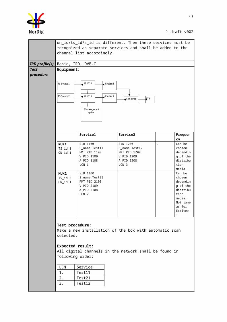
()
1 draft v002
Minimum input level (dBm) for PP4Profile 1: Gaussian
Profile 2:0 dB echo
Frequency bandVHF
Band IIIVHF
S Band I & II
VHFS Band I & II and
UHFS Band III
UHFBand IV&V
VHFBand III
UHFBand IV&V
1.7 MHz signal 7 MHz signal 7 MHz signal 8 MHz signal 8 MHz signal 1.7 MHz signal 7 MHz signal 8 MHz signal
ModulationCode Rate
“30 secerror free
video”
BER1E-7after
LDPC
“30 secerror free
video”
BER1E-7after
LDPC
“30 secerrorfree
video”
BER1E-7after
LDPC
“30 secerror free
video”
BER1E-7after
LDPC
“30 secerror free
video”
BER1E-7after
LDPC
“30 secerror free
video”
BER1E-7after
LDPC
“30 secerror free
video”
BER1E-7after
LDPC
“30 secerror free
video”
BER1E-7after
LDPCQPSK 1/2 -102.0 -102.0 -96.6 -96.6 -92.6 -92.6 -92.0 -92.0 -96.0 -96.0 -100.3 -100.3 -94.9 -94.9 -94.3 -94.3QPSK 3/5 -100.8 -100.8 -95.4 -95.4 -91.4 -91.4 -90.8 -90.8 -94.8 -94.8 -98.7 -98.7 -93.3 -93.3 -92.7 -92.7QPSK 2/3 -99.9 -99.9 -94.5 -94.5 -90.5 -90.5 -89.9 -89.9 -93.9 -93.9 -97.1 -97.1 -91.7 -91.7 -91.1 -91.1QPSK 3/4 -98.9 -98.9 -93.5 -93.5 -89.5 -89.5 -88.9 -88.9 -92.9 -92.9 -95.7 -95.7 -90.3 -90.3 -89.7 -89.7QPSK 4/5 -98.3 -98.3 -92.9 -92.9 -88.9 -88.9 -88.3 -88.3 -92.3 -92.3 -94.6 -94.6 -89.2 -89.2 -88.6 -88.6QPSK 5/6 -97.8 -97.8 -92.4 -92.4 -88.4 -88.4 -87.8 -87.8 -91.8 -91.8 -93.5 -93.5 -88.1 -88.1 -87.5 -87.5
16-QAM 1/2 -96.8 -96.8 -91.4 -91.4 -87.4 -87.4 -86.8 -86.8 -90.8 -90.8 -94.6 -94.6 -89.2 -89.2 -88.6 -88.616-QAM 3/5 -95.4 -95.4 -90.0 -90.0 -86.0 -86.0 -85.4 -85.4 -89.4 -89.4 -92.8 -92.8 -87.4 -87.4 -86.8 -86.816-QAM 2/3 -94.1 -94.1 -88.7 -88.7 -84.7 -84.7 -84.1 -84.1 -88.1 -88.1 -91.2 -91.2 -85.8 -85.8 -85.2 -85.216-QAM 3/4 -93.0 -93.0 -87.6 -87.6 -83.6 -83.6 -83.0 -83.0 -87.0 -87.0 -89.3 -89.3 -83.9 -83.9 -83.3 -83.316-QAM 4/5 -92.2 -92.2 -86.8 -86.8 -82.8 -82.8 -82.2 -82.2 -86.2 -86.2 -87.7 -87.7 -82.3 -82.3 -81.7 -81.716-QAM 5/6 -91.7 -91.7 -86.3 -86.3 -82.3 -82.3 -81.7 -81.7 -85.7 -85.7 -86.6 -86.6 -81.2 -81.2 -80.6 -80.664-QAM 1/2 -92.5 -92.5 -87.1 -87.1 -83.1 -83.1 -82.5 -82.5 -86.5 -86.5 -89.6 -89.6 -84.2 -84.2 -83.6 -83.664-QAM 3/5 -90.7 -90.7 -85.3 -85.3 -81.3 -81.3 -80.7 -80.7 -84.7 -84.7 -87.5 -87.5 -82.1 -82.1 -81.5 -81.564-QAM 2/3 -89.4 -89.4 -84.0 -84.0 -80.0 -80.0 -79.4 -79.4 -83.4 -83.4 -85.9 -85.9 -80.5 -80.5 -79.9 -79.964-QAM 3/4 -87.8 -87.8 -82.4 -82.4 -78.4 -78.4 -77.8 -77.8 -81.8 -81.8 -83.6 -83.6 -78.2 -78.2 -77.6 -77.664-QAM 4/5 -86.8 -86.8 -81.4 -81.4 -77.4 -77.4 -76.8 -76.8 -80.8 -80.8 -81.6 -81.6 -76.2 -76.2 -75.6 -75.664-QAM 5/6 -86.2 -86.2 -80.8 -80.8 -76.8 -76.8 -76.2 -76.2 -80.2 -80.2 -80.1 -80.1 -74.7 -74.7 -74.1 -74.1256-QAM 1/2 -88.6 -88.6 -83.2 -83.2 -79.2 -79.2 -78.6 -78.6 -82.6 -82.6 -84.9 -84.9 -79.5 -79.5 -78.9 -78.9256-QAM 3/5 -86.2 -86.2 -80.8 -80.8 -76.8 -76.8 -76.2 -76.2 -80.2 -80.2 -82.5 -82.5 -77.1 -77.1 -76.5 -76.5256-QAM 2/3 -84.7 -84.7 -79.3 -79.3 -75.3 -75.3 -74.7 -74.7 -78.7 -78.7 -80.5 -80.5 -75.1 -75.1 -74.5 -74.5256-QAM 3/4 -82.7 -82.7 -77.3 -77.3 -73.3 -73.3 -72.7 -72.7 -76.7 -76.7 -77.7 -77.7 -72.3 -72.3 -71.7 -71.7256-QAM 4/5 -81.3 -81.3 -75.9 -75.9 -71.9 -71.9 -71.3 -71.3 -75.3 -75.3 -74.9 -74.9 -69.5 -69.5 -68.9 -68.9256-QAM 5/6 -80.5 -80.5 -75.1 -75.1 -71.1 -71.1 -70.5 -70.5 -74.5 -74.5 -72.4 -72.4 -67.0 -67.0 -66.4 -66.4
Table 2.10Minimum DVB-T2 signal input levels (Pmin) for “30 seconds error free video” and BER 1E-7 after LDPC for PP4 and for any allowed combination of guard interval, FFT size and extended carrier mode. Values are equal for normal carrier mode except for 8MHz signal BW where 0.1dB is substracted. Before 1.1.2012 the values for non-S-band channels may be increased with 1 dB, excluding 1.7MHz bandwidth columns, due to a 1 dB relaxation in noise figure.
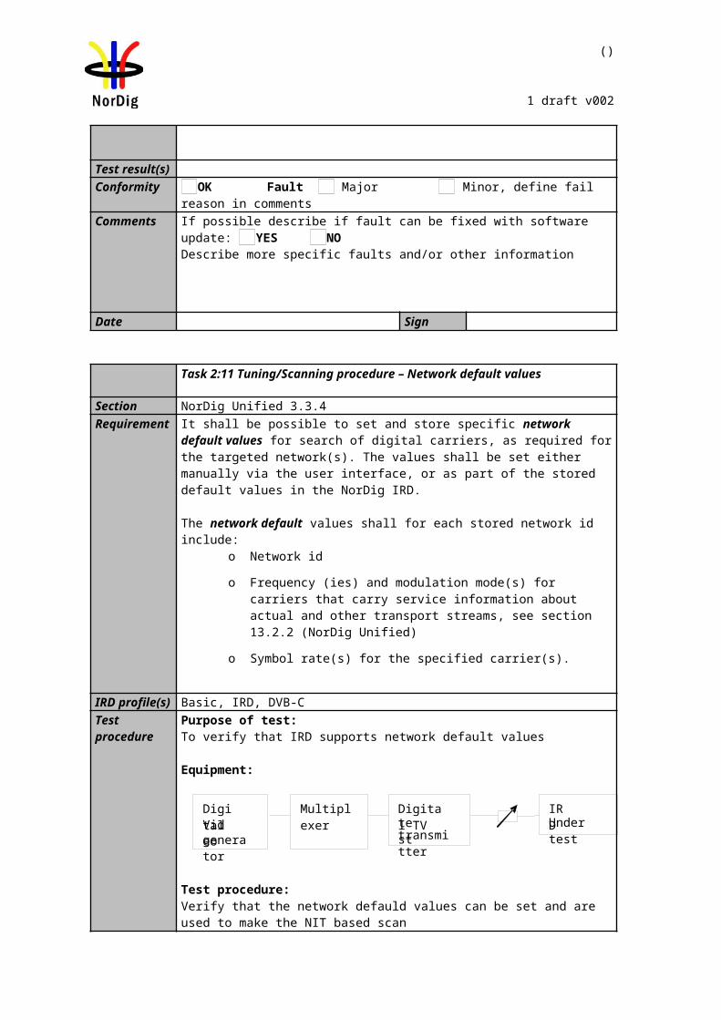
()
1 draft v002
Minimum input level (dBm) for PP6Profile 1: Gaussian
Profile 2:0 dB echo
Frequency bandVHF
Band IIIVHF
S Band I & II
VHFS Band I & II and
UHFS Band III
UHFBand IV&V
VHFBand III
UHFBand IV&V
1.7 MHz signal 7 MHz signal 7 MHz signal 8 MHz signal 8 MHz signal 1.7 MHz signal 7 MHz signal 8 MHz signal
ModulationCode Rate
“30 secerror free
video”
BER1E-7after
LDPC
“30 secerror free
video”
BER1E-7after
LDPC
“30 secerrorfree
video”
BER1E-7after
LDPC
“30 secerror free
video”
BER1E-7after
LDPC
“30 secerror free
video”
BER1E-7after
LDPC
“30 secerror free
video”
BER1E-7after
LDPC
“30 secerror free
video”
BER1E-7after
LDPC
“30 secerror free
video”
BER1E-7after
LDPCQPSK 1/2 -102.5 -102.5 -97.1 -97.1 -93.1 -93.1 -92.5 -92.5 -96.5 -96.5 -100.8 -100.8 -95.4 -95.4 -94.8 -94.8QPSK 3/5 -101.3 -101.3 -95.9 -95.9 -91.9 -91.9 -91.3 -91.3 -95.3 -95.3 -99.2 -99.2 -93.8 -93.8 -93.2 -93.2QPSK 2/3 -100.4 -100.4 -95.0 -95.0 -91.0 -91.0 -90.4 -90.4 -94.4 -94.4 -97.6 -97.6 -92.2 -92.2 -91.6 -91.6QPSK 3/4 -99.4 -99.4 -94.0 -94.0 -90.0 -90.0 -89.4 -89.4 -93.4 -93.4 -96.2 -96.2 -90.8 -90.8 -90.2 -90.2QPSK 4/5 -98.8 -98.8 -93.4 -93.4 -89.4 -89.4 -88.8 -88.8 -92.8 -92.8 -95.1 -95.1 -89.7 -89.7 -89.1 -89.1QPSK 5/6 -98.3 -98.3 -92.9 -92.9 -88.9 -88.9 -88.3 -88.3 -92.3 -92.3 -94.0 -94.0 -88.6 -88.6 -88.0 -88.0
16-QAM 1/2 -97.3 -97.3 -91.9 -91.9 -87.9 -87.9 -87.3 -87.3 -91.3 -91.3 -95.1 -95.1 -89.7 -89.7 -89.1 -89.116-QAM 3/5 -95.9 -95.9 -90.5 -90.5 -86.5 -86.5 -85.9 -85.9 -89.9 -89.9 -93.3 -93.3 -87.9 -87.9 -87.3 -87.316-QAM 2/3 -94.6 -94.6 -89.2 -89.2 -85.2 -85.2 -84.6 -84.6 -88.6 -88.6 -91.7 -91.7 -86.3 -86.3 -85.7 -85.716-QAM 3/4 -93.5 -93.5 -88.1 -88.1 -84.1 -84.1 -83.5 -83.5 -87.5 -87.5 -89.7 -89.7 -84.3 -84.3 -83.7 -83.716-QAM 4/5 -92.7 -92.7 -87.3 -87.3 -83.3 -83.3 -82.7 -82.7 -86.7 -86.7 -88.2 -88.2 -82.8 -82.8 -82.2 -82.216-QAM 5/6 -92.2 -92.2 -86.8 -86.8 -82.8 -82.8 -82.2 -82.2 -86.2 -86.2 -87.1 -87.1 -81.7 -81.7 -81.1 -81.164-QAM 1/2 -93.0 -93.0 -87.6 -87.6 -83.6 -83.6 -83.0 -83.0 -87.0 -87.0 -90.1 -90.1 -84.7 -84.7 -84.1 -84.164-QAM 3/5 -91.2 -91.2 -85.8 -85.8 -81.8 -81.8 -81.2 -81.2 -85.2 -85.2 -88.0 -88.0 -82.6 -82.6 -82.0 -82.064-QAM 2/3 -89.8 -89.8 -84.4 -84.4 -80.4 -80.4 -79.8 -79.8 -83.8 -83.8 -86.4 -86.4 -81.0 -81.0 -80.4 -80.464-QAM 3/4 -88.3 -88.3 -82.9 -82.9 -78.9 -78.9 -78.3 -78.3 -82.3 -82.3 -84.1 -84.1 -78.7 -78.7 -78.1 -78.164-QAM 4/5 -87.3 -87.3 -81.9 -81.9 -77.9 -77.9 -77.3 -77.3 -81.3 -81.3 -82.1 -82.1 -76.7 -76.7 -76.1 -76.164-QAM 5/6 -86.7 -86.7 -81.3 -81.3 -77.3 -77.3 -76.7 -76.7 -80.7 -80.7 -80.7 -80.7 -75.3 -75.3 -74.7 -74.7256-QAM 1/2 -89.0 -89.0 -83.6 -83.6 -79.6 -79.6 -79.0 -79.0 -83.0 -83.0 -85.4 -85.4 -80.0 -80.0 -79.4 -79.4256-QAM 3/5 -86.7 -86.7 -81.3 -81.3 -77.3 -77.3 -76.7 -76.7 -80.7 -80.7 -83.0 -83.0 -77.6 -77.6 -77.0 -77.0256-QAM 2/3 -85.2 -85.2 -79.8 -79.8 -75.8 -75.8 -75.2 -75.2 -79.2 -79.2 -81.0 -81.0 -75.6 -75.6 -75.0 -75.0256-QAM 3/4 -83.2 -83.2 -77.8 -77.8 -73.8 -73.8 -73.2 -73.2 -77.2 -77.2 -78.3 -78.3 -72.9 -72.9 -72.3 -72.3256-QAM 4/5 -81.8 -81.8 -76.4 -76.4 -72.4 -72.4 -71.8 -71.8 -75.8 -75.8 -75.6 -75.6 -70.2 -70.2 -69.6 -69.6256-QAM 5/6 -81.0 -81.0 -75.6 -75.6 -71.6 -71.6 -71.0 -71.0 -75.0 -75.0 -73.3 -73.3 -67.9 -67.9 -67.3 -67.3
Table 2.11Minimum DVB-T2 signal input levels (Pmin) for “30 seconds error free video” and BER 1E-7 after LDPC for PP6 and for any allowed combination of guard interval, FFT size and extended carrier mode. Values are equal for normal carrier mode except for 8MHz signal BW where 0.1dB is substracted. Before 1.1.2012 the values for non-S-band channels may be increased with 1 dB, excluding 1.7MHz bandwidth columns, due to a 1 dB relaxation in noise figure.
()
1 draft v002
Minimum input level (dBm) for PP7Profile 1: Gaussian
Profile 2:0 dB echo
Frequency bandVHF
Band IIIVHF
S Band I & II
VHFS Band I & II and
UHFS Band III
UHFBand IV&V
VHFBand III
UHFBand IV&V
1.7 MHz signal 7 MHz signal 7 MHz signal 8 MHz signal 8 MHz signal 1.7 MHz signal 7 MHz signal 8 MHz signal
ModulationCode Rate
“30 secerror free
video”
BER1E-7after
LDPC
“30 secerror free
video”
BER1E-7after
LDPC
“30 secerrorfree
video”
BER1E-7after
LDPC
“30 secerror free
video”
BER1E-7after
LDPC
“30 secerror free
video”
BER1E-7after
LDPC
“30 secerror free
video”
BER1E-7after
LDPC
“30 secerror free
video”
BER1E-7after
LDPC
“30 secerror free
video”
BER1E-7after
LDPCQPSK 1/2 -102.7 -102.7 -97.3 -97.3 -93.3 -93.3 -92.7 -92.7 -96.7 -96.7 -101.0 -101.0 -95.6 -95.6 -95.0 -95.0QPSK 3/5 -101.5 -101.5 -96.1 -96.1 -92.1 -92.1 -91.5 -91.5 -95.5 -95.5 -99.4 -99.4 -94.0 -94.0 -93.4 -93.4QPSK 2/3 -100.6 -100.6 -95.2 -95.2 -91.2 -91.2 -90.6 -90.6 -94.6 -94.6 -97.8 -97.8 -92.4 -92.4 -91.8 -91.8QPSK 3/4 -99.6 -99.6 -94.2 -94.2 -90.2 -90.2 -89.6 -89.6 -93.6 -93.6 -96.4 -96.4 -91.0 -91.0 -90.4 -90.4QPSK 4/5 -99.0 -99.0 -93.6 -93.6 -89.6 -89.6 -89.0 -89.0 -93.0 -93.0 -95.2 -95.2 -89.8 -89.8 -89.2 -89.2QPSK 5/6 -98.5 -98.5 -93.1 -93.1 -89.1 -89.1 -88.5 -88.5 -92.5 -92.5 -94.1 -94.1 -88.7 -88.7 -88.1 -88.1
16-QAM 1/2 -97.5 -97.5 -92.1 -92.1 -88.1 -88.1 -87.5 -87.5 -91.5 -91.5 -95.2 -95.2 -89.8 -89.8 -89.2 -89.216-QAM 3/5 -96.1 -96.1 -90.7 -90.7 -86.7 -86.7 -86.1 -86.1 -90.1 -90.1 -93.4 -93.4 -88.0 -88.0 -87.4 -87.416-QAM 2/3 -94.7 -94.7 -89.3 -89.3 -85.3 -85.3 -84.7 -84.7 -88.7 -88.7 -91.8 -91.8 -86.4 -86.4 -85.8 -85.816-QAM 3/4 -93.6 -93.6 -88.2 -88.2 -84.2 -84.2 -83.6 -83.6 -87.6 -87.6 -89.9 -89.9 -84.5 -84.5 -83.9 -83.916-QAM 4/5 -92.8 -92.8 -87.4 -87.4 -83.4 -83.4 -82.8 -82.8 -86.8 -86.8 -88.4 -88.4 -83.0 -83.0 -82.4 -82.416-QAM 5/6 -92.3 -92.3 -86.9 -86.9 -82.9 -82.9 -82.3 -82.3 -86.3 -86.3 -87.2 -87.2 -81.8 -81.8 -81.2 -81.264-QAM 1/2 -93.1 -93.1 -87.7 -87.7 -83.7 -83.7 -83.1 -83.1 -87.1 -87.1 -90.2 -90.2 -84.8 -84.8 -84.2 -84.264-QAM 3/5 -91.3 -91.3 -85.9 -85.9 -81.9 -81.9 -81.3 -81.3 -85.3 -85.3 -88.2 -88.2 -82.8 -82.8 -82.2 -82.264-QAM 2/3 -90.0 -90.0 -84.6 -84.6 -80.6 -80.6 -80.0 -80.0 -84.0 -84.0 -86.5 -86.5 -81.1 -81.1 -80.5 -80.564-QAM 3/4 -88.5 -88.5 -83.1 -83.1 -79.1 -79.1 -78.5 -78.5 -82.5 -82.5 -84.2 -84.2 -78.8 -78.8 -78.2 -78.264-QAM 4/5 -87.4 -87.4 -82.0 -82.0 -78.0 -78.0 -77.4 -77.4 -81.4 -81.4 -82.3 -82.3 -76.9 -76.9 -76.3 -76.364-QAM 5/6 -86.8 -86.8 -81.4 -81.4 -77.4 -77.4 -76.8 -76.8 -80.8 -80.8 -80.8 -80.8 -75.4 -75.4 -74.8 -74.8256-QAM 1/2 -89.2 -89.2 -83.8 -83.8 -79.8 -79.8 -79.2 -79.2 -83.2 -83.2 -85.6 -85.6 -80.2 -80.2 -79.6 -79.6256-QAM 3/5 -86.8 -86.8 -81.4 -81.4 -77.4 -77.4 -76.8 -76.8 -80.8 -80.8 -83.1 -83.1 -77.7 -77.7 -77.1 -77.1256-QAM 2/3 -85.4 -85.4 -80.0 -80.0 -76.0 -76.0 -75.4 -75.4 -79.4 -79.4 -81.2 -81.2 -75.8 -75.8 -75.2 -75.2256-QAM 3/4 -83.4 -83.4 -78.0 -78.0 -74.0 -74.0 -73.4 -73.4 -77.4 -77.4 -78.5 -78.5 -73.1 -73.1 -72.5 -72.5256-QAM 4/5 -81.9 -81.9 -76.5 -76.5 -72.5 -72.5 -71.9 -71.9 -75.9 -75.9 -75.8 -75.8 -70.4 -70.4 -69.8 -69.8256-QAM 5/6 -81.2 -81.2 -75.8 -75.8 -71.8 -71.8 -71.2 -71.2 -75.2 -75.2 -73.5 -73.5 -68.1 -68.1 -67.5 -67.5
Table 2.12Minimum DVB-T2 signal input levels (Pmin) for “30 seconds error free video” and BER 1E-7 after LDPC for PP7 and for any allowed combination of guard interval, FFT size and extended carrier mode. Values are equal for normal carrier mode except for 8MHz signal BW where 0.1dB is substracted. Before 1.1.2012 the values for non-S-band channels may be increased with 1 dB, excluding 1.7MHz bandwidth columns, due to a 1 dB relaxation in noise figure.
79 (457)
NorDig Unified Test plan, ver 2.6.0
2.3.3 Bitrates
The different DVB-T/T2 modes define different bitrates for the transport stream. The following table defines the bitrates for the transport stream in Mbit/s. For DVB-T2 bit rate calculation combination highest time interleaving depth and highest number of symbols per frame resulting highest bit rate is used.
8MHz, 2k / 8kModulation FEC Tg=1/32 Tg=1/16 Tg=1/8 Tg=1/4
QPSK 1/2 6.032086 5.854671 5.529412 4.976471QPSK 2/3 8.042781 7.806228 7.372549 6.635294QPSK 3/4 9.048128 8.782007 8.294118 7.464706QPSK 5/6 10.053476 9.757785 9.215686 8.294118QPSK 7/8 10.556150 10.245675 9.676471 8.708824
16QAM 1/2 12.064171 11.709343 11.058824 9.95294116QAM 2/3 16.085561 15.612457 14.745098 13.27058816QAM 3/4 18.096257 17.564014 16.588235 14.92941216QAM 5/6 20.106952 19.515571 18.431373 16.58823516QAM 7/8 21.112299 20.491349 19.352941 17.41764764QAM 1/2 18.096257 17.564014 16.588235 14.92941264QAM 2/3 24.128342 23.418685 22.117647 19.90588264QAM 3/4 27.144385 26.346021 24.882353 22.39411864QAM 5/6 30.160428 29.273356 27.647059 24.88235364QAM 7/8 31.668449 30.737024 29.029412 26.126471
Table 2.13 Bitrates for the transport stream in Mbit/s for 8MHz DVB-T signal bandwidth.
7MHz, 2k / 8kModulation FEC Tg=1/32 Tg=1/16 Tg=1/8 Tg=1/4
QPSK 1/2 5.278075 5.122837 4.838235 4.354412QPSK 2/3 7.037433 6.830450 6.450980 5.805882QPSK 3/4 7.917112 7.684256 7.257353 6.531618QPSK 5/6 8.796791 8.538062 8.063725 7.257353QPSK 7/8 9.236631 8.964965 8.466912 7.620221
16QAM 1/2 10.556150 10.245675 9.676471 8.70882416QAM 2/3 14.074866 13.660900 12.901961 11.61176516QAM 3/4 15.834225 15.368512 14.514706 13.06323516QAM 5/6 17.593583 17.076125 16.127451 14.51470616QAM 7/8 18.473262 17.929931 16.933824 15.24044164QAM 1/2 15.834225 15.368512 14.514706 13.06323564QAM 2/3 21.112299 20.491349 19.352941 17.41764764QAM 3/4 23.751337 23.052768 21.772059 19.59485364QAM 5/6 26.390374 25.614187 24.191176 21.77205964QAM 7/8 27.709893 26.894896 25.400735 22.860662
Table 2.14 Bitrates for the transport stream in Mbit/s for 7MHz DVB-T signal bandwidth.
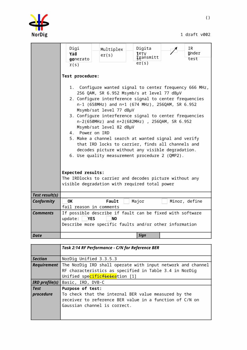
80 (457)
NorDig Unified Test plan, ver 2.6.0
‘
8MHz, 32k extended, L1-ACE & TR PAPRModulation FEC PP Tg=1/128 Tg=1/32 Tg=1/16 Tg=19/256 Tg=1/8256QAM
rotated 3/5 PP4 N/A 33.843523 32.849069 32.491052 N/APP6 N/A 34.520394 N/A N/A N/A
256QAM rotated 2/3
PP4 N/A 37.658458 36.551906 - N/APP6 N/A 38.411627 N/A N/A N/APP7 39.8164804 N/A N/A N/A N/A
256QAM rotated 3/4
PP2 N/A N/A - - 37.120437PP4 N/A 42.364012 41.119193 - N/APP7 44.7916868 N/A N/A N/A N/A
Table 2.15 Bitrates for the transport stream in Mbit/s for 8MHz DVB-T2 signal bandwidth.
7MHz, 32k normal, L1-ACE & TR PAPRModulation FEC PP Tg=1/128 Tg=1/32 Tg=1/16 Tg=19/256 Tg=1/8
256QAM rotated 3/5
PP2 N/A N/A 26.870949 - 25.386712PP4 N/A 28.975435 28.123999 - N/APP7 30.527312 N/A N/A N/A N/A
256QAM rotated 2/3
PP2 N/A N/A 29.899917 - 28.248373PP4 N/A 32.241626 31.294213 30.953132 N/APP7 33.968435 N/A N/A N/A N/A
256QAM rotated 3/4
PP2 N/A N/A 33.636014 - 31.778104PP4 N/A 36.270328 35.204533 - N/APP7 38.212908 N/A N/A N/A N/A
Table 2.16 Bitrates for the transport stream in Mbit/s for 7MHz DVB-T2 signal bandwidth.
1.7MHz, 8k normal, L1-ACE & TR PAPRModulation FEC PP Tg=1/128 Tg=1/32 Tg=1/16 Tg=1/8
256QAM rotated 2/3 PP2 N/A N/A N/A 6.324006
Table 2.17 Bitrates for the transport stream in Mbit/s for 1.7MHz DVB-T2 signal bandwidth.
The video and audio compression technique of the content within transport stream doesn’t have any influence to RF performance test results. Therefore, following content compression with given bit rate applies for all tests excluding DVB-T2 receiver buffel model tests where requirement for lower transport stream bit rate is necessary in order to stress the receiver buffer correctly.
Normal test content conditions:The used video is MPEG-2 elementary stream in resolution 720x576. The video bitrate within transport stream is 4.0 Mbit/s.
The used audio is MPEG-1 elementary stream in stereo mode. The audio bitrate is 128kbit/s per channel.
Test tasks Task 3:40, Task 3:41, Task 3:42 and Task 3:45:A transport stream bit rate shall be equal or below 3.3 MBit/s. Video and audio content carried within transport stream shall be selected so that transport stream bit rate condition is met.
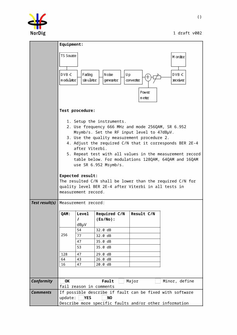
81 (457)
NorDig Unified Test plan, ver 2.6.0
2.3.4 Receiver operability in SFN
The SFN synchronisation of the receiver depends on the echo delay and attenuation level in the SFN. The SFN synchronisation of the receiver may also depend of the state of the receiver. Therefore, it is important to evaluate if the receiver synchronises differently in the following situations:
1. When the receiver is restarted completely (AC cord disconnected). 2. When the receiver is powered on in standby mode. The last good SFN synchronisation parameters can
be saved to memory for faster SFN synchronisation leading that the dynamical change of the delay during the receiver is in standby mode gives bad result on power up.
3. During the channel search. 4. Connecting and disconnecting the input RF signal (closing and opening of the RF switch as in test
cases). Discontinued input RF signal tests the SFN synchronisation algorithm when the receiver is forced to an unlocked state, e.g. when transmission is discontinued.
5. Zapping between services on different frequencies. Different frequencies have different echo delays and attenuation levels. This corresponds the real reception.
6. During the over-the-air software upgrade. If the demodulator is not correctly controlled during the software download, the SFN synchronisation problems can lead that the software cannot be updated.
Evaluation of the SFN synchronisation can be done e.g. when an echo delay and amplitude level combination is founded to be difficult to synchronise. In that case methods above are tested. Decide which method can be used to evaluate the SFN synchronisation algorithm of the receiver. Check also that all the other methods work. Independtly of the state of the receiver all the listed methods above shall work.
The receiver shall detect correct synchronization in SFN, maintain it and provide reception quality at required quality level independently if the received signal changes from bad conditions to good conditions or vice versa. E.g. when testing and finding the required C/N in test cases, the receiver must be able to detect correct synchronization in SFN, maintain it and provide reception quality at defined quality level when C/N value is changed from low (bad reception condition) value to higher (better reception condition) value.
2.3.5 0dB echo
The 0 degree channel center shall be used in fading simulator. In this context it means that the carriers from the direct and echo signal are cumulative. See figure below for 0dB 1.95µs echo.
2.3.6 Conditions for analoque TVThe level of the analog TV signal is defined to be the power during the sync pulse of the vision carrier. The power of the sync pulse of the vision carrier shall be measured when the video input of the analogue TV modulator is connected to 75ohm load, in other words, there is no modulation in the vision carrier. 10% modulation depth is used for vision carrier.

82 (457)
NorDig Unified Test plan, ver 2.6.0
The level of the FM sound relative to the vision carrier is –13 dB.The frequency of FM sound carrier is +5.5 MHz relative to vision carrier.
The level of the NICAM signal relative to the vision carrier is –20 dB. The frequency of the NICAM carrier is +5.85MHz relative to vision carrier.
It shall be verified that the analog TV signal doesn’t have too high out-of-band emissions, which could cause interference to other frequencies.
The equipment used for generation of the analog TV shall be connected to same frequency reference signal as the digital TV equipment.
2.3.7 Summary of DVB-T2 modes in DVB-T2 test tasksManufacture shall ensure the functionality of the receiver in all required DVB-T2 parameter settings specified in (1). Also, manufacture shall ensure the performance as required in (1) for the subset of the DVB-T2 modes although in test cases the amount of the DVB-T2 may have been reduced in order to minimase the test time.
Summary of mandatory parameters settings for single and multiple PLP DVB-T2 modes are listed in Table 2.176 and Table 2.187 used in DVB-T2 test tasks. In every test case any deviations to the common parameters are specified.
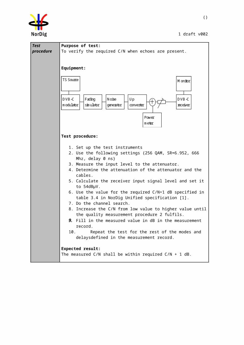
83 (457)
NorDig Unified Test plan, ver 2.6.0
NU_S1 NU_S2,NU_S3
NU_S4.NU_S5
NU_S6, NU_S7, NU_S8
NU_S9, NU_S10, NU_S11
NU_S12, NU_S13, NU_S14
NU_S15 … NU_S26NU_S27, NU_S28, NU_S29
NU_S30, NU_S31, NU_S32
NU_S33, NU_S34
NU_S35, NU_S36, NU_S37
NU_S38 … N_S49
Bandwidth 1.7MHz 7MHz 7MHz 7MHz 7MHz 7MHz 7MHz 8MHz 8MHz 8MHz 8MHz 8MHz
FFT 8k 32k 32k 32k 32k 32k 32k 32k 32k 32k 32k 32k
Carrier mode Normal Normal Normal Normal Normal Normal Normal Extended Extended Extended Extended Extended
SISO/MISO SISO SISO SISO SISO SISO SISO SISO SISO SISO SISO SISO SISO
Guard Interval 1/8 1/8 19/256 1/16 1/16 1/32 1/128 1/8 19/256 1/16 1/32 1/128
Version 1.2.1 1.2.1 1.2.1 1.2.1 1.2.1 1.2.1 1.2.1 1.2.1 1.2.1 1.2.1 1.2.1 1.2.1
Lf 49 22,44 22,42 22,44,56 22,42,56 20,42,58
20,42,60 (QPSK)20,42,60 (16QAM)20.40,60 (64QAM)
20,40,60 (256QAM)
22,44,60 20,42,62 42,62 20,42,62
20,42,60 (QPSK)20,42,60 (16QAM)20.40,60 (64QAM)
20,40,60 (256QAM)
Pilot pattern PP2 PP2 PP4 PP2 PP4 PP4 PP7 PP2 PP4 PP4 PP4 PP7
TFS No No No No No No No No No No No No
FEF Not used Not used Not used Not used Not used Not used Not used Not used Not used Not used Not used Not used
Auxiliary streams Not used Not used Not used Not used Not used Not used Not used Not used Not used Not used Not used Not used
Cell ID *) *) *) *) *) *) *) *) *) *) *) *)
Network ID *) *) *) *) *) *) *) *) *) *) *) *)
T2 System ID *) *) *) *) *) *) *) *) *) *) *) *)
Subslices / T2 frame 1 1 1 1 1 1 1 1 1 1 1 1
Frames / Superframe 2 2 2 2 2 2 2 2 2 2 2 2
L1 FEC type 16k LDPC 16k LDPC 16k LDPC 16k LDPC 16k LDPC 16k LDPC 16k LDPC 16k LDPC 16k LDPC 16k LDPC 16k LDPC 16k LDPC
L1 repetition 0 0 0 0 0 0 0 0 0 0 0 0
L1 extension No No No No No No No No No No No No
L1 modulation 64QAM
64QAM
64QAM
64QAM
64QAM
64QAM
64QAM
64QAM
64QAM
64QAM
64QAM
64QAM
L1_ACE_MAX 0 0 0 0 0 0 0 0 0 0 0 0
L1 bias balancing cells No No No No No No No No No No No No
PAPR L1-ACE & TR
L1-ACE & TR
L1-ACE & TR
L1-ACE & TR
L1-ACE & TR L1-ACE & TR L1-ACE & TR L1-ACE &
TRL1-ACE &
TRL1-ACE &
TRL1-ACE &
TR L1-ACE & TR
PAPR: Vclip 3.1V 3.1V 3.1V 3.1V 3.1V 3.1V 3.1V 3.1V 3.1V 3.1V 3.1V 3.1V
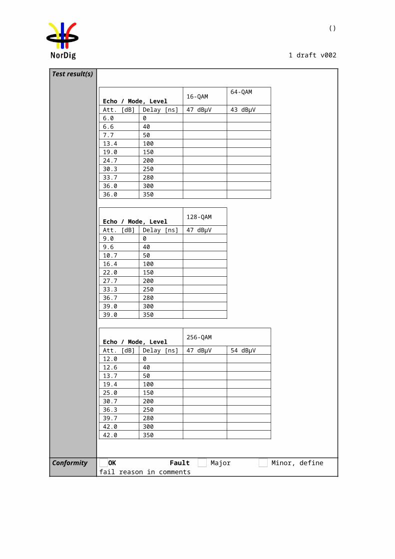
84 (457)
NorDig Unified Test plan, ver 2.6.0
NU_S1 NU_S2,NU_S3
NU_S4.NU_S5
NU_S6, NU_S7, NU_S8
NU_S9, NU_S10, NU_S11
NU_S12, NU_S13, NU_S14
NU_S15 … NU_S26NU_S27, NU_S28, NU_S29
NU_S30, NU_S31, NU_S32
NU_S33, NU_S34
NU_S35, NU_S36, NU_S37
NU_S38 … N_S49
PAPR: Number of iterations 10 10 10 10 10 10 10 10 10 10 10 10
Input TS bit rate [MBit/s] 4.5 4.5 4.5 4.5 4.5 4.5 4.5 4.5 4.5 4.5 4.5 4.5
Number of PLPs 1 1 1 1 1 1 1 1 1 1 1 1
PLP id *) *) *) *) *) *) *) *) *) *) *) *)
Group id *) *) *) *) *) *) *) *) *) *) *) *)
PLP type Data type 1 Data type 1 Data type 1 Data type 1 Data type 1 Data type 1 Data type 1 Data type 1 Data type 1 Data type 1 Data type 1 Data type 1
Constellation rotation Yes Yes Yes Yes Yes Yes Yes Yes Yes Yes Yes Yes
PLP FEC type 64k LDPC 64k LDPC 64k LDPC 64k LDPC 64k LDPC 64k LDPC 64k LDPC 64k LDPC 64k LDPC 64k LDPC 64k LDPC 64k LDPC
FEC Frame length 64800 64800 64800 64800 64800 64800 64800 64800 64800 64800 64800 64800
Baseband Mode
High efficiency
mode (HEM)
High efficiency
mode (HEM)
High efficiency
mode (HEM)
High efficiency
mode (HEM)
High efficiency
mode (HEM)
High efficiency
mode (HEM)
High efficiency mode (HEM)
High efficiency
mode (HEM)
High efficiency
mode (HEM)
High efficiency
mode (HEM)
High efficiency
mode (HEM)
High efficiency mode (HEM)
ISSY Long Long Long Long Long Long Long Long Long Long Long Long
In band signaling Disabled Disabled Disabled Disabled Disabled Disabled Disabled Disabled Disabled Disabled Disabled Disabled
Null packet deletion Enabled Enabled Enabled Disabled Disabled Disabled Disabled Disabled Disabled Disabled Disabled Disabled
Time interval blocks per frame TBD TBD TBD TBD TBD TBD TBD TBD TBD TBD TBD TBD
Time interleaver length 3 3 3 3 3 3 3 3 3 3 3 3
Frame interval 1 1 1 1 1 1 1 1 1 1 1 1
Time interleaver type 0 0 0 0 0 0 0 0 0 0 0 0
T2 frames / Interleaver frame 1 1 1 1 1 1 1 1 1 1 1 1
FEC Blocks /Interleaving Frame 36 65,132 68,132 66,133,169 68,132,176 62,132,183
16,34,48 (QPSK)32,68,97 (16QAM)
48.97,146 (64QAM)64,130,195 (256QAM)
67,135,185 63,135,200 135,200 64,135,200
16,34,50 (QPSK)33,69,100 (16QAM)49.99,150 (64QAM)
66,133,200 (256QAM)Code rate 2/3 3/4 2/3 3/4 3/5,2/3,3/4 3/5,2/3,3/4 All 3/4 3/5 3/5, 2/3, 3/4 3/5,2/3,3/4 All
Modulation 256QAM
256QAM
256QAM
256QAM
256QAM
256QAM
256QAM
256QAM
256QAM
256QAM
256QAM
256QAM
BUFS TBD TBD TBD TBD TBD TBD TBD TBD TBD TBD TBD TBD
Design Delay TBD TBD TBD TBD TBD TBD TBD TBD TBD TBD TBD TBD
85 (457)
NorDig Unified Test plan, ver 2.6.0
Table 2.18 DVB-T2 mode parameters in DVB-T2 Single PLP (mode A) test tasks. *) any allowed value
NU_M1 NU_M2 (VV702-TDICC3) NU_M3 (VV708-DJBCC2) NU_M4 (VV710-TDICC1)
Bandwidth 8MHz 8MHz 8MHz 8MHz
FFT 32k 32k 32k 32k
Carrier mode Extended Extended Extended Extended
SISO/MISO SISO SISO SISO SISO
Guard Interval 1/16 1/128 1/128 1/128
Version 1.2.1 1.2.1 1.2.1 1.2.1
Lf 28 **) 28 **) 28 **) 28 **)
Pilot pattern PP4 PP7 PP7 PP7
TFS No No No No
FEF Not used Not used Not used Used
Auxiliary streams Not used Not used Not used Not used
Cell ID *) *) *) *)
Network ID *) *) *) *)
T2 System ID *) *) *) *)
Subslices / T2 frame 135 1 108 108
Frames / Superframe 2 2 2 4
L1 FEC type 16k LDPC 16k LDPC 16k LDPC 16k LDPC
L1 repetition 0 0 0 0
L1 extension No No No No
L1 Modulation 64QAM 16QAM 16QAM 16QAM
L1_ACE_MAX 0 0 0 0
L1 bias balancing cells No No No No
PAPR L1-ACE & TR L1-ACE & TR L1-ACE & TR L1-ACE & TR
PAPR: Vclip 3.1V Infinity Infinity Inifinity
PAPR: Number of 10 TBD TBD TBD
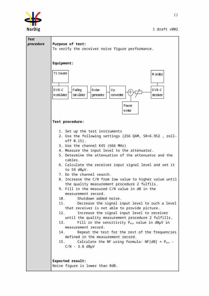
86 (457)
NorDig Unified Test plan, ver 2.6.0
NU_M1 NU_M2 (VV702-TDICC3) NU_M3 (VV708-DJBCC2) NU_M4 (VV710-TDICC1)
iterationsInput TS bit rate [MBit/s] TBD 36.234886 38.030308 5955840/178801 = 33.309880
Number of PLPs 3 5 5 5
PLP id 0 1 2 0 1 2 3 4 0 1 2 3 4 0 1 2 3 4
Constellation rotation Yes Yes Yes Yes Yes Yes Yes Yes Yes Yes Yes Yes Yes Yes Yes Yes Yes Yes
PLP FEC type 16k LDPC
64k LDPC
64k LDPC
64k LDPC
64k LDPC
64k LDPC
64k LDPC
16k LDPC
64k LDPC
64k LDPC
64k LDPC
64k LDPC
16k LDPC
64k LDPC
64k LDPC
64k LDPC
64k LDPC
16k LDPC
FEC Frame length 16200 64800 64800 TBD TBD TBD TBD TBD TBD TBD TBD TBD TBD TBD TBD TBD TBD TBD
Baseband Mode HEM HEM HEM HEM HEM HEM HEM HEM HEM HEM HEM HEM HEM HEM HEM HEM HEM HEM
ISSY Long Long Long Long Long Long Long Long Long Long Long Long Long Long Long Long Long Long
In band signaling Type A & B
Type A & B
Type A & B Type A Type A Type A Type A Type A Type A Type A Type A Type A Type A Type A Type A Type A Type A Type A
Number of other PLPs in-band signalling 0 0 0 0 0 0 0 0 0 0 0 0 0 0 0 0 0 0
Null packet deletion Enabled Enabled Enabled Enabled Enabled Enabled Enabled Enabled Enabled Enabled Enabled Enabled Enabled Enabled Enabled Enabled Enabled Enabled
Time interval blocks per frame TBD TBD TBD 1 1 1 1 1 1 1 1 1 1 1 1 1 1 1
Time interleaver length 1 1 1 1 1 1 1 1 1 1 1 1 1 1 1 1 1 1
Frame interval 1 1 1 1 1 1 1 1 1 1 1 1 1 1 1 1 1 1
Time interleaver type 0 0 0 0 0 0 0 0 0 0 0 0 0 0 0 0 0 0
T2 frames / Interleaver frame 1 1 1 1 1 1 1 1 1 1 1 1 1 1 1 1 1 1
First frame index 0 0 0 0 0 0 0 0 0 0 0 0 0 0 0 0 0 0
Group id 1 1 1 0 0 0 0 0 0 0 0 0 0 0 0 0 0 0
PLP type Common DT 2 DT 2 DT 1 DT 1 DT 1 DT 1 Common DT 2 DT 2 DT 2 DT 2 Common DT2 DT2 DT2 DT2 Common
FEC Blocks /Interleaving Frame
Non-dynamic
35
Non-dynamic
57
Non-dynamic
57
Dynamic max 57
Dynamic max 57
Dynamic max 22
Dynamic max 22 17 Dynamic
max 57Dynamic max 57
Dynamic max 57
Dynamic max 57 35 Dynamic
max 57Dynamic max 57
Dynamic max 57
Dynamic max 57 33
Total FEC blocks TBD TBD TBD 85 85 85 85 17 82 82 82 82 35 81 81 81 81 33
Max cells / T2 frame TBD TBD TBD 688500 688500 688500 688500 45900 TBD TBD TBD TBD TBD 656100 656100 656100 656100 89100
Code rate 2/3 2/3 2/3 2/3 2/3 2/3 2/3 2/3 2/3 2/3 2/3 2/3 2/3 2/3 2/3 2/3 2/3 2/3
Modulation 64QAM
256QAM
256QAM 256 QAM 256
QAM 256 QAM 256 QAM 64 QAM 256 QAM 256 QAM 256 QAM 256 QAM 64QAM 256 QAM
256 QAM
256 QAM
256 QAM 64QAM
BUFS 483328 1613824 1613824 1613824 1613824 1613824 1613824 483328 1671168 1671168 1671168 1671168 425984 1662976 1662976 1662976 1662976 434176
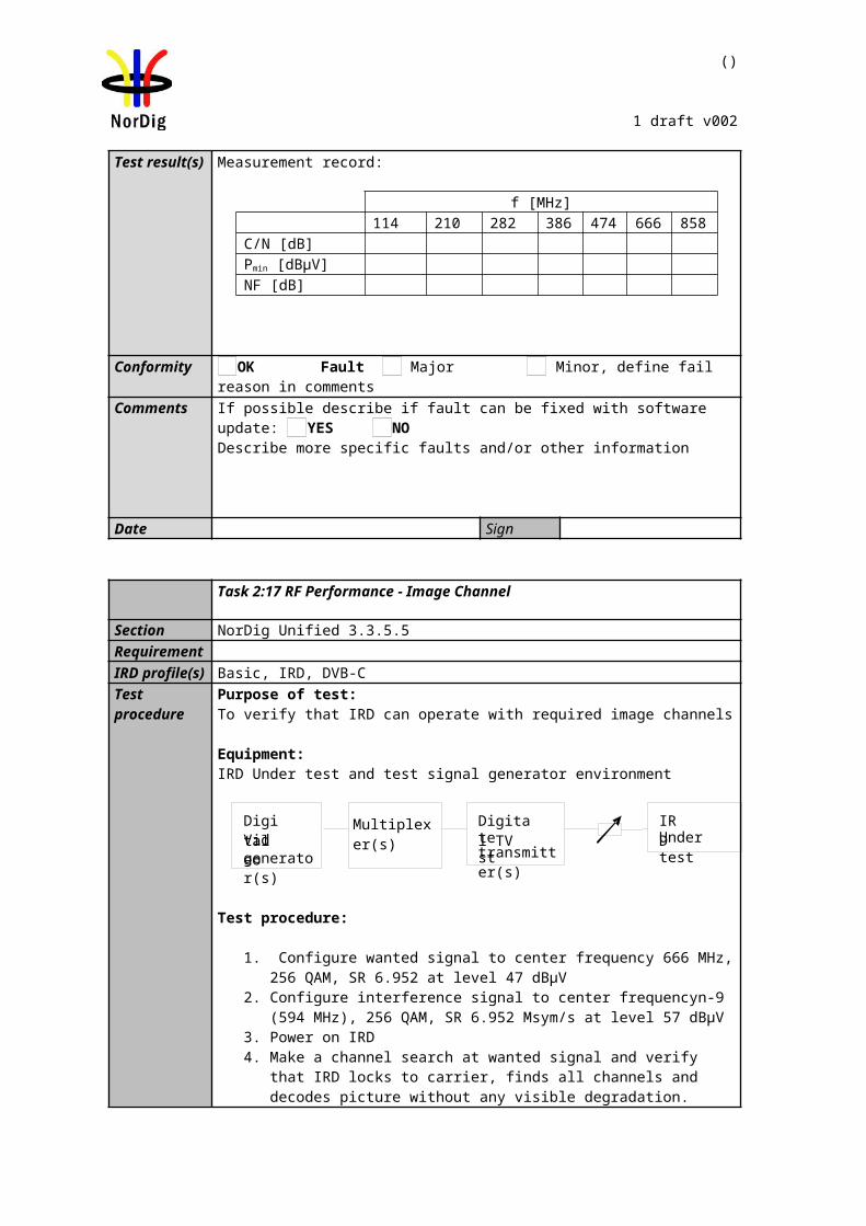
87 (457)
NorDig Unified Test plan, ver 2.6.0
NU_M1 NU_M2 (VV702-TDICC3) NU_M3 (VV708-DJBCC2) NU_M4 (VV710-TDICC1)
Design delay 989615 989615 989615 939080 939080 939080 939080 939080 935798 935798 935798 935798 935798 939195 939195 939195 939195 939195
Table 2.19 DVB-T2 mode parameters in DVB-T2 Multiple PLP (mode B) test tasks. *) any allowed value **) maximum achieved value may depend on content in PLPs
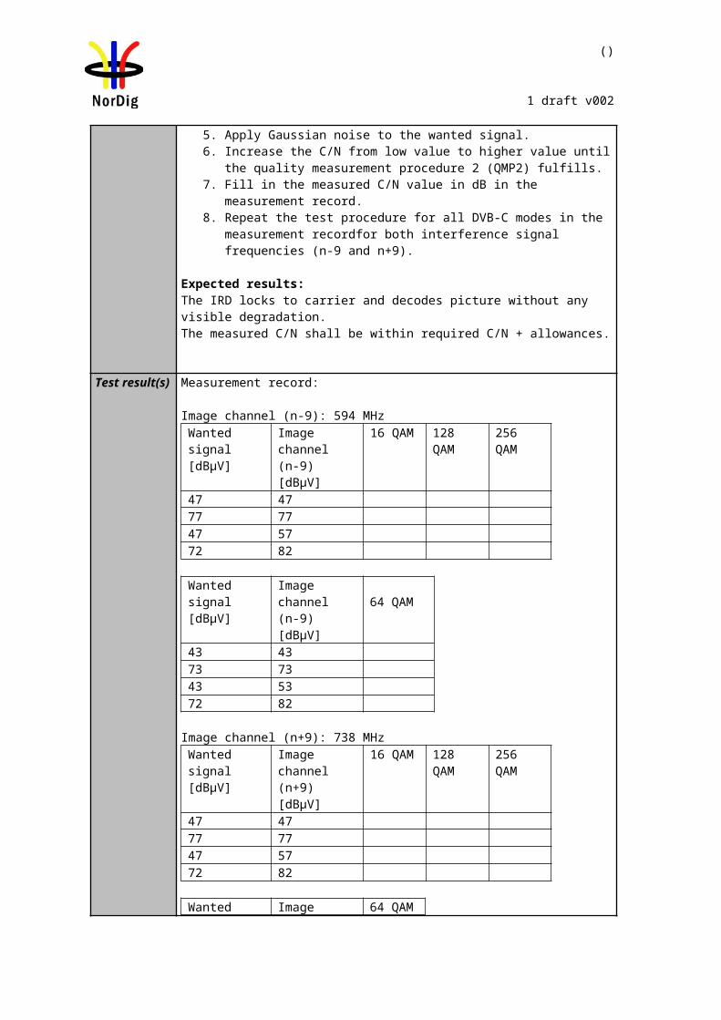
88 (457)
NorDig Unified Test plan, ver 2.6.0
Due to the deployment situation for DVB-T2 transmissions in networks is different, several alternativities for Lf and FEC blocks / interleaving frame are given.
Normally signal bandwidth of the DVB-T2 mode is specified for the on-air signals on VHF and UHF frequencies. For off-air signals in cable networks the signal bandwidth relation to frequency band is not obvious, e.g. when reception from on-air 8MHz signal bandwidth on UHF is downcoverted to VHF off-air distribution.
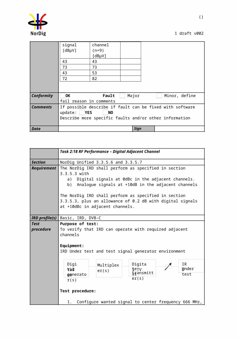
89 (457)
NorDig Unified Test plan, ver 2.6.0
2.3.8 Stream packet structure in Receiver Buffer Model (RBM) tests for DVB-T2
Test tasks Task 3:40, Task 3:41, Task 3:42 and Task 3:45 stress the receiver buffer model. TS contains a service with a real video and audio. Prerequisite is that the modulator shall support V&V packet generation architecture. Figure 1 shows Task 3:40 chapter 2 packet structure. Compilation of the TSs to PLPs and recompilation back to TSs are explained more detailed in [4]. Video and audio content carried within common PLP is used for test purposes in order to make it possible to test IRD subjectively.Most probably that is not a normal use of common PLP although common PLP allows contain video and audio content. To make sure broadcast network operator’s use of common PLP, the broadcast network operator should be consulted.
Defined RBM test method can only test one PLP at a time, therefore the RBM tests have to be run with a separate stream for each PLP to be tested.
Chapter 2, 1 repetition, M=22, RunLength[TS0]=20, Runlength[TS1]=27, Runlength[TS2]=2 and Runlength[TS3]=2PacketIndex 0 1 2 3 4 5 6 7 8 9 10 11 12 13 14 15 16 17 18 19 20 21 22 23 24 25 26 27 28 29 30 31 32 33 34 35 36 37 38 39 40 41 42 43 44 45 46 47 48 49 50
TS0TS1TS2TS3
TSx mapping into PLPx in a modulator
PLP0PLP1PLP2PLP3
PLP4 (Common)
PLPx mapping into TSx in an IRD
TS0 Valid TS for decodingTS1 Invalid TS for decodingTS2TS3
= Null Packet =TS0 packet =TS1 packet =TS2 packet =TS3 packet=modified common slot TS0 packet containing A/V content
Figure 1. Example of compilation of Task 3:40 TSs to PLPs and recompilation back to TSs. Figure shows only chapter 2 where repetition is 1 for a modulator supporting V&V stream compilation and IRD demodulating the received DVB-T2 signal. The recompiled TS0 results to a valid TS for decoding.
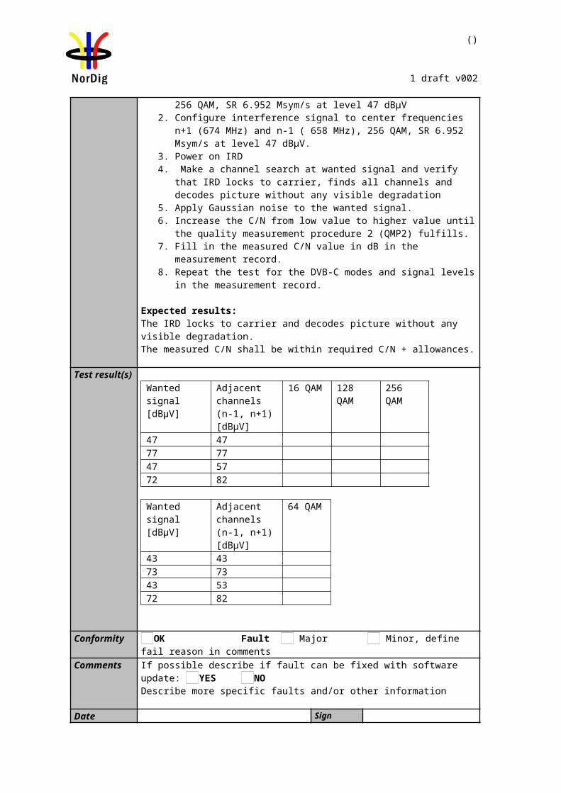
90 (457)
NorDig Unified Test plan, ver 2.6.0
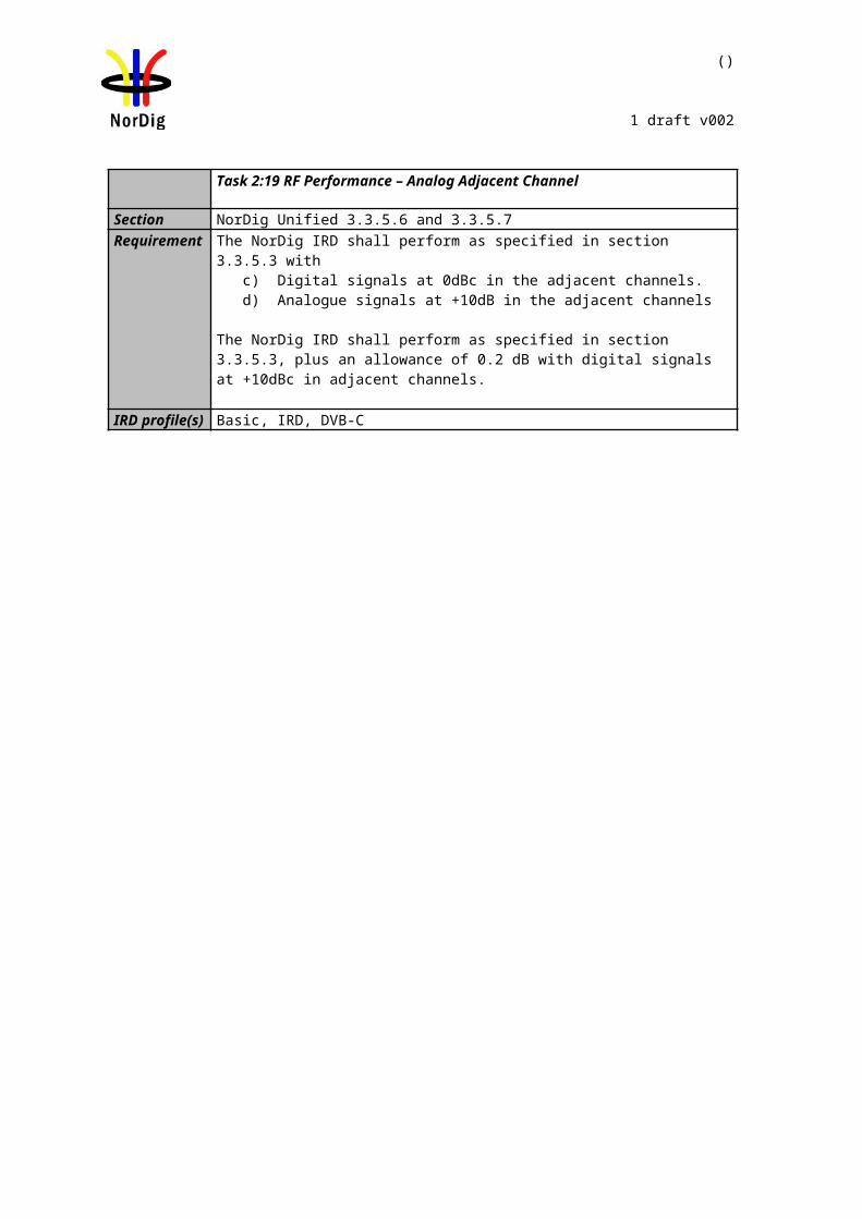
91 (457)
NorDig Unified Test plan, ver 2.6.0
2.3.9 Test cases
2.3.9.1 Test cases – DVB-T IRD
Test Case Task 3:1 General
Section NorDig Unified 3.4.1Requirement The NorDig IRD shall include at least one tuner/demodulator for reception of signals
from terrestrial transmitters, broadcasting in accordance with EN 300 744 [21] (DVB-T).
IRD profile(s) Basic, IRD, DVB-TTest procedure Purpose of test:
To verify the possibility of the reception of the DVB-T signal.
Equipment:An IRD.Test procedure:Make sure that the IRD has one tuner/demodulator for reception of terrestrial signals.
Expected result:IRD has one tuner/demodulator for terrestrial reception.
Test result(s)Conformity OK Fault Major Minor, define fail reason in commentsComments If possible describe if fault can be fixed with software update: YES NO
Describe more specific faults and/or other information
Date Sign
Test Case Task 3:2 General
Section NorDig Unified 3.1.2IRD profile(s) Basic, IRD, DVB-TRequirement The NorDig IRD shall be able to automatically scan through the whole frequency range
available for each of the available Tuners/Demodulators and tune in to the correct DVB framing structure, channel coding and modulation to deliver the incoming transport stream to the next units. The tuning data shall be stored in a service list, in order to allow a quick tune in to the selected transport stream. For more detail see below.
Test procedure Purpose of test:To verify that IRD is able to scan through the whole frequency range.
Test procedure:This is common requirement and will be verified in the following tests.
Test result(s) The manufacturer describes his specific setup for the testConformity OK Fault Major Minor, define fail reason in commentsComments If possible describe if fault can be fixed with software update: YES NO
Describe more specific faults and/or other information
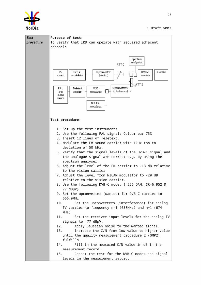
92 (457)
NorDig Unified Test plan, ver 2.6.0
Date Sign
Test Case Task 3:3 Quality reception detector
Section NorDig Unified 3.1.3Requirement The NorDig Unified receiver shall be equipped with a reception quality detector.
IRD profile(s) Basic, IRD, DVB-TTest procedure Equipment:
IRD under test.
Test procedure:Check that the IRD is equipped with a reception quality detector
Expected result: It shall be possible to access some kind of a reception quality detector.
Test result(s)
Conformity OK Fault Major Minor, define fail reason in commentsComments If possible describe if fault can be fixed with software update: YES NO
Describe more specific faults and/or other information
Date Sign
Test Case Task 3:4 Frequencies: Center frequencies
Section NorDig Unified 3.4.2.1 and 3.4.2.2Requirement The NorDig IRD shall be able to receive channels in VHF band III and UHF bands IV,
V and should be able to receive channels in VHF S band I, VHF S band II, UHF S Band III.
The front-end shall for the supported frequency ranges be capable of tuning to the center frequency fc of the incoming DVB-T RF signal, see below.
8MHz raster: fc = 114 MHz +K * 8 MHz, where K = 0 … 93
7MHz raster: fc= 107.5 MHz + L * 7 MHz, where L = 0 … 27
IRD profile(s) Basic, IRD, DVB-TTest procedure Purpose of test:
To verify the reception over the supported frequency range.
Equipment:MonitorDVB-T
ReceiverUp-converterDVB-T
modulatorMPEG-2source
Test procedure:
1. Set up the test instruments2. Use the following mode 8k 64QAM, HP Code rate=2/3, Guard interval TU/8
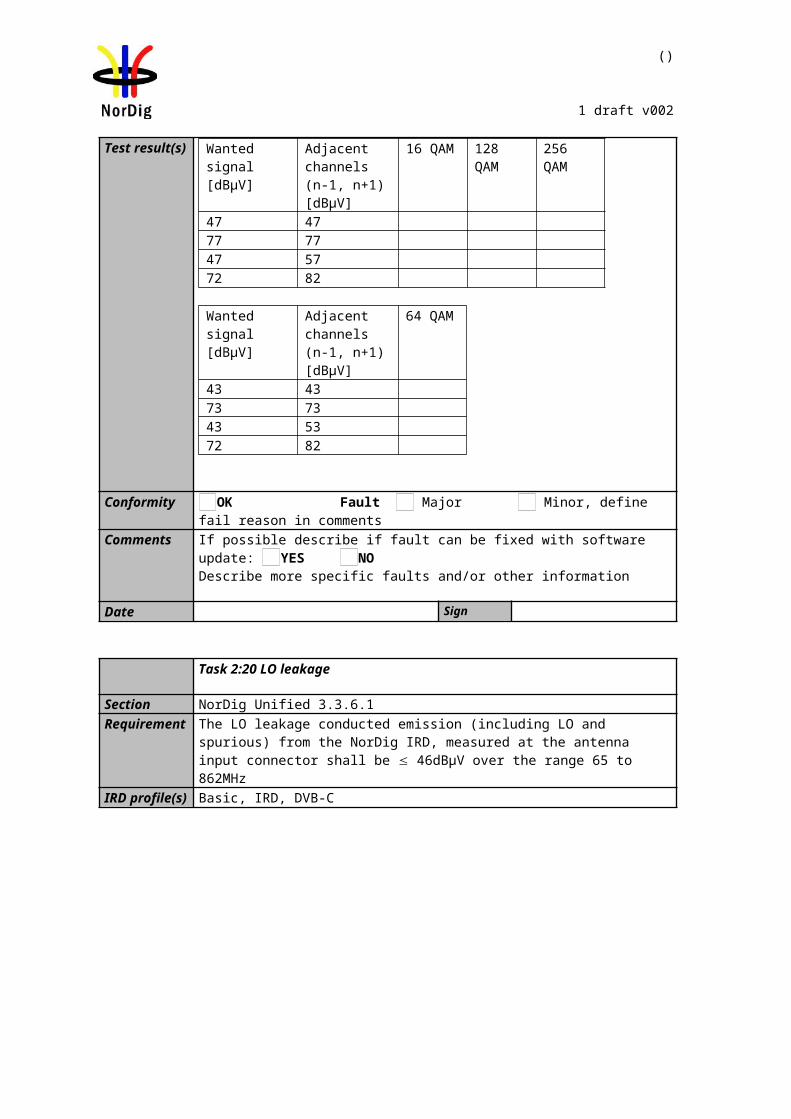
93 (457)
NorDig Unified Test plan, ver 2.6.0
3. Use input level of -60 dBm4. Start with frequency 177,5MHz (K5) 5. Use the quality measurement procedures 1 (QMP1).6. Fill the result in the measurement record: OK or NOK.7. Repeat the test for all channels in the table 1 in the measurement record. 8. If the receiver supports optional frequency ranges, test all remaining channels
in table 2 and 3 in the measurement record.
Expected result: The result of the test shall be OK for all channels in table 1.
For the optionally supported frequency ranges, the tests shall be OK for the channels in the tables 2 and 3.
94 (457)
NorDig Unified Test plan, ver 2.6.0
Test result(s)Band Channel Frequency
[MHz]BW
[MHz]Result
OK or NOK
VHF III
K5 177.5 7K6 184.5 7K7 191.5 7K8 198.5 7K9 205.5 7K10 212.5 7K11 219.5 7K12 226.5 7
UHFIV/V
K21 474 8K22 482 8K23 490 8K24 498 8K25 506 8K26 514 8K27 522 8K28 530 8K29 538 8K30 546 8K31 554 8K32 562 8K33 570 8K34 578 8K35 586 8K36 594 8K37 602 8K38 610 8K39 618 8K40 626 8K41 634 8K42 642 8K43 650 8K44 658 8K45 666 8K46 674 8K47 682 8K48 690 8K49 698 8K50 706 8K51 714 8K52 722 8K53 730 8K54 738 8K55 746 8K56 754 8K57 762 8K58 770 8K59 778 8K60 786 8K61 794 8K62 802 8K63 810 8K64 818 8K65 826 8K66 834 8K67 842 8K68 850 8K69 858 8
Table 1. Mandatory center frequencies and signal bandwidths to receive
95 (457)
NorDig Unified Test plan, ver 2.6.0
Test result(s) Band Channel Frequency [MHz]
BW [MHz]
Result 7MHz OK or NOK
BW [MHz]
Result 8MHzOK or NOK
VHFS I
D1 114.0 7 8S2 114.5 7 8S3 121.5 7 8D2 122.0 7 8S4 128.5 7 8D3 130.0 7 8S5 135.5 7 8D4 138.0 7 8S6 142.5 7 8D5 146.0 7 8S7 149.5 7 8D6 154.0 7 8S8 156.5 7 8D7 162.0 7 8S9 163.5 7 8D8 170.0 7 8S10 170.5 7 8
VHF III
K5 177.5 7 8D9 178.0 7 8K6 184.5 7 8D10 186.0 7 8K7 191.5 7 8D11 194.0 7 8K8 198.5 7 8D12 202.0 7 8K9 205.5 7 8D13 210.0 7 8K10 212.5 7 8D14 218.0 7 8K11 219.5 7 8D15 226.0 7 8K12 226.5 7 8
VHFS II
S11 233.5 7 8D16 234.0 7 8S12 240.5 7 8D17 242.0 7 8S13 247.5 7 8D18 250.0 7 8S14 254.5 7 8D19 258.0 7 8S15 261.5 7 8D20 266.0 7 8S16 268.5 7 8D21 274.0 7 8S17 275.5 7 8D22 282.0 7 8S18 282.5 7 8S19 289.5 7 8D23 290.0 7 8S20 296.5 7 8D24 298.0 7 8
Table 2 Optional VHF center frequencies and signal bandwidths to receive.
96 (457)
NorDig Unified Test plan, ver 2.6.0
Test results(s)Band Channel Frequency
[MHz]BW
[MHz]Result
OK or NOK
UHFS III
S21 306.0 8S22 314.0 8S23 322.0 8S24 330.0 8S25 338.0 8S26 346.0 8S27 354.0 8S28 362.0 8S29 370.0 8S30 378.0 8S31 386.0 8S32 394.0 8S33 402.0 8S34 410.0 8S35 418.0 8S36 426.0 8S37 434.0 8S38 442.0 8S39 450.0 8S40 458.0 8S41 466.0 8
Table 3 Optional UHF center frequencies and signal bandwidth to receive.
Conformity OK Fault Major Minor, define fail reason in commentsComments If possible describe if fault can be fixed with software update: YES NO
Describe more specific faults and/or other information
Date Sign
Test Case Task 3:5 Frequencies: Frequency offset
Section NorDig Unified 3.4.2.3Requirement The NorDig IRD shall be able to receive signals with an offset of up to 50kHz from the
nominal frequency.
IRD profile(s) Basic, IRD, DVB-TTest procedure Purpose of test:
To verify that the reception is possible in specified frequency offset from nominal frequency.
Equipment:
Test procedure:1. Set up the test instruments
97 (457)
NorDig Unified Test plan, ver 2.6.0
2. Use the following mode: 8k, 64QAM, Code rate=2/3, Guard interval TU/83. Use input level of -60 dBm4. Set the center frequency to 177.5 MHz and frequency offset to 0 kHz. Use
signal bandwidth 7MHz. 5. Connect receiver and do the channel search if needed.6. Test with the specified frequency offset values in the measurement record.
Before changing the frequency offset, disconnect the receiver from the received RF signal.
7. Do the change of frequency offset, 8. Connect the received RF signal back to the receiver. 9. Use the quality measurement procedure 1 (QMP1)10. Fill the result in the measurement record: OK or NOK.11. Test the remaining frequency offset values on specified center frequencies and
signal bandwidths in the measurement record.
Expected result:The test shall be OK for all frequency offset values on specified center frequencies and signal bandwidths.
Test result(s)Channel Signal BW
[MHz]Frequency
[MHz]Offset[kHz]
ResultOK or NOK
K57 177.5 -507 177.5 07 177.5 +50
K127 226.5 -507 226.5 07 226.5 +50
K218 474.0 -508 474.0 08 474.0 +50
K698 858.0 -508 858.0 08 858.0 +50
Conformity OK Fault Major Minor, define fail reason in commentsComments If possible describe if fault can be fixed with software update: YES NO
Describe more specific faults and/or other information
Date Sign
Test Case Task 3:6 Frequencies: Signal bandwidths
Section NorDig Unified 3.4.2.4Requirement VHF Bands:
The NorDig IRD shall for the supported frequency ranges be able to receive 7 MHz and should be able to receive 8 MHz DVB-T signals. If 8 MHz bandwidth is supported it shall automatically detect which DVB-T signal bandwidth is being used, and it shall be possible to receive the 8 MHz DVB-T signals on the 7 MHz channel frequency raster.
UHF Bands:The NorDig IRD shall for the supported frequency ranges be able to receive 8 MHz
98 (457)
NorDig Unified Test plan, ver 2.6.0
DVB-T signals.
(For a DVB-T signal, an 8 MHz DVB-T signal corresponds to a signal bandwidth of 7.61 MHz and a 7 MHz DVB-T signal corresponds to a signal bandwidth of 6.66 MHz.)
IRD profile(s) Basic, IRD, DVB-TTest procedure Purpose of test:
To verify that the receiver is able to automatically detect the transmitted signal bandwidth and do the required adaptations for QEF reception.
(The reception of the different signal bandwidths on supported frequency ranges are tested in previous test).
Equipment:MonitorDVB-T
ReceiverUp-converterDVB-T
modulatorMPEG-2source
Test procedure:
1. Set up the test instruments.2. Use the transmission frequency UHF IV/V 666 MHz (K45) and an input level
of -60 dBm to the receiver.3. Use the DVB-T mode 8k 64QAM FEC R=2/3 /Tu=1/8 and signal bandwidth
8MHz.4. Connect the receiver and perform an automatic or manual channel search. The
signal bandwidth initialization shall not be required by the user. 5. Use the quality measurement procedure 1.6. Fill the result in the measurement record: OK or NOK.7. Change the transmission frequency to VHF III channel 198.5 MHz (K8) and
signal bandwidth to 7 MHz.8. Verify that the channel list does not have any services installed by performing
initialization to factory defaults or in such way.9. Do an automatic or manual channel search. The signal bandwidth initialization
shall not be required by the user.10. Use the quality measurement procedure 1 (QMP1).11. Fill the result in the measurement record: OK or NOK.
Expected result:The test results shall be OK for all tests in the table 1 in the measurement record and user does not have to initialize the signal bandwidth for the succesfull channel search and QEF reception.
If 8MHz signal bandwidth in VHF is supported the test result shall be OK for the test in the table 2 in the measurement record. If the 8MHz signal bandwidth in VHF is not supported, this test result can be NOK.
Test result(s) Measurement record:
Channel Frequency[MHz]
Signal bandwidth[MHz]
ResultOK or NOK
K8 198.5 7K45 666.0 8
Table 1 Mandatory signal bandwidths to receive
Channel Frequency Signal bandwidth Result
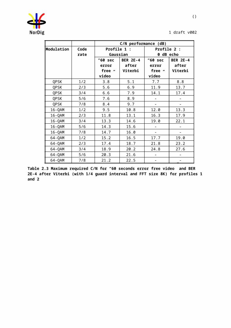
99 (457)
NorDig Unified Test plan, ver 2.6.0
[MHz] [MHz] OK or NOKK8 198.5 8
Table 2 Optional signal bandwidth to receive.
Conformity OK Fault Major Minor, define fail reason in commentsComments If possible describe if fault can be fixed with software update: YES NO
Describe more specific faults and/or other information
Date Sign
Test Case Task 3:7 Modes
Section NorDig Unified 3.4.3Requirement The NorDig IRD terrestrial front end shall be capable of correctly demodulating all non-
hierarchical modes specified in EN 300 744.
The front end shall therefore be able to work with any combination of constellation (QPSK, 16-QAM or 64-QAM), code rate (1/2, 2/3, ¾, 5/6 or 7/8), guard interval (TU/4, TU/8, TU/16 or TU/32) and transmission mode (2K or 8K).
The IRD shall automatically detect which mode is being used.
The NorDig IRD should be able to receiver the hierarchical modes in the DVB-T specification.
IRD profile(s) Basic, IRD, DVB-TTest procedure Purpose of test:
To verify the reception of all non-hierarchical DVB-T modes.
Equipment:MonitorDVB-T
ReceiverUp-converterDVB-T
modulatorMPEG-2source
Test procedure:
1. Set up the test instruments.2. Use channel 45 and an input level of -60 dBm.3. Start with the mode 8k QPSK FEC R=1/2 /Tu=1/32 and signal bandwidth 8
MHz.4. Use the quality measurement procedure 1 (QMP1).5. Fill the result in the measurement record: OK or NOK.6. Perform the same test for the remaining 119 8k and 2k modes.
Expected result:The test shall be OK for all modes.
Test result(s) Measurement record:
8K FEC Tg=1/32 Tg=1/16 Tg=1/8 Tg=1/4QPSK ½QPSK 2/3

100 (457)
NorDig Unified Test plan, ver 2.6.0
QPSK ¾QPSK 5/6QPSK 7/816QAM ½16QAM 2/316QAM ¾16QAM 5/616QAM 7/864QAM ½64QAM 2/364QAM ¾64QAM 5/664QAM 7/8
2K FEC Tg=1/32 Tg=1/16 Tg=1/8 Tg=1/4QPSK ½QPSK 2/3QPSK ¾QPSK 5/6QPSK 7/816QAM ½16QAM 2/316QAM ¾16QAM 5/616QAM 7/864QAM ½64QAM 2/364QAM ¾64QAM 5/664QAM 7/8
Conformity OK Fault Major Minor, define fail reason in commentsComments If possible describe if fault can be fixed with software update: YES NO
Describe more specific faults and/or other information
Date Sign
Test Case Task 3:8 Tuning/Scanning Procedure: General
Section NorDig Unified 3.4.4.1Requirement The IRD shall be able to provide a scanning procedure over the whole frequency range.
It shall also be able to receive and react on tuning parameters found in PSI/SI (e.g. NIT information).?
IRD profile(s) Basic, IRD, DVB-TTest procedure Purpose of test:
To verify that IRD is able to scan throught the whole frequency range.
Test procedure:This is common requirement and will be verified in the following tests.
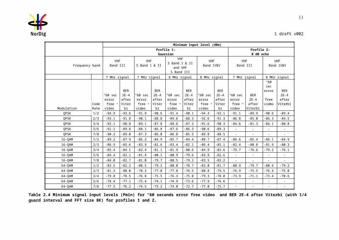
101 (457)
NorDig Unified Test plan, ver 2.6.0
Test result(s)Conformity OK Fault Major Minor, define fail reason in commentsComments If possible describe if fault can be fixed with software update: YES NO
Describe more specific faults and/or other information
Date Sign
Test Case Task 3:9 Tuning/Scanning Procedures: Basic status check
Section NorDig Unified 3.4.4.2Requirement The IRD shall provide at least a basic status check function (accessible through the
Navigator) that presents reception quality information for a selected service (currently viewed by the user).
The basic status check should be presented on the OSD and shall include:channel id and center frequencysignal strength indicator andreception quality indicator
IRD profile(s) Basic, IRD, DVB-TTest procedure Purpose of test:
To verify that all the specified status information is displayed.
Equipment:
Test procedure:
1. Use DVB-T mode 8k 64QAM R=3/4 /Tu=1/4. 2. Tune the IRD to an arbitrary service.3. Locate the status check function in the navigator and initiate it.4. Check that the channel number, signal strength and the reception quality indicators
are displayed.5. Use gaussian channel configuration in fading simulator. 6. Try several input signal levels from such a low input level (no picture att all) to a
high input level by changing the attenuation in the attenuator. 7. Decide if the indicated values of the signal strength indicator are reasonable. 8. After each change of input signal level check that the signal strength indicator is
updated. 9. Configure 0dB 105µs echo in fading simulator and variate the C/N.

102 (457)
NorDig Unified Test plan, ver 2.6.0
10. Evaluate if the reception quality corresponds the real reception quality by changing the C/N from a low value to a high value. After each change of C/N check that the reception quality indicator is updated.
11. Fill in the test protocol.
Expected result:All test results are OK.
Test result(s) Measurement record
Requirement NOK or OKNavigator has status check function.The function shows the channel id andcenter frequency. The function shows signal strength indicator. .Signal strength indicator is updated continuously.The function has reception quality indicator.Signal quality indicator is updated continuously.
Conformity OK Fault Major Minor, define fail reason in commentsComments If possible describe if fault can be fixed with software update: YES NO
Describe more specific faults and/or other information
Date Sign
Test Case Task 3:10 Tuning/Scanning Procedures: Automatic channel search for the same service bouquet
Section NorDig Unified 3.4.4.4Requirement The terrestrial NorDig IRD shall provide an automatic search that finds all of the
multiplexes and services in the whole (supported) frequency range, see NorDig specification. The logic of the automatic search function shall be as follows:
If any services are detected during the automatic search the current service list shall be replaced by the new service list.If no services are detected during the automatic search the current service list shall be kept or deleted.
The IRD shall only display a service once in the service list (i.e. avoiding duplicate of the same services), even if the same service (same triplet original_network_id, transport_stream_id and service_id) is received from multiple transmitters. If the same service can be received from several transmitters, the one with best reception quality shall be selected. The criteria for selection of the best received service (i.e. best reception quality) shall be based on the combination of the signal strength and signal quality according to NorDig specification.
IRD profile(s) Basic, IRD, DVB-TTest procedure Purpose of test:
To verify the best service selection in automatic channel search when the content of the transport stream is the same on several transmitters.
103 (457)
NorDig Unified Test plan, ver 2.6.0
Equipment:
Channels A and BTS source #1ONID=8945
Network ID=1000Network Name=Net1
TSID=100Services
Name SID Logic Ch NoS1 1 1S2 2 2S3 3 3S4 4 4
There is a possibility to receive broadcasts from several transmitters simultaneously in DVB-T network. These transmitters can have exactly the same content, but are transmitted on different channels (frequencies). Therefore, it is important that the receiver can choose by an automatic channel search the services with the best reception quality.
Test to verify broadcast where equal services are broadcasted simultaneously over DVB-T and DVB-T2 networks is not required.
Reception quality can be divided into two different parameters: Signal strength Signal quality
Signal quality can be divided into two main parameters: Signal-to-noise ratio (C/N) Bit error rate before Reed Solomon (BER before RS in DVB-T system)
Channels A and B shall not be equal.
Relative signal levels can be observed on spetrum analyser.
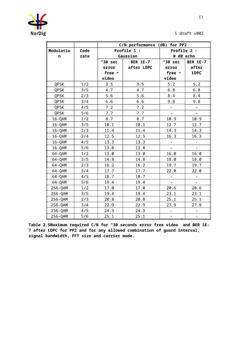
104 (457)
NorDig Unified Test plan, ver 2.6.0
∆S refers to difference in SSI according to [1] Annex D.
∆Q refers to difference in SQI according to [1] Annex D.
AWGN refers to Additive White Gaussian Noise.
Test points 10-13 in table 1920 below require the BER in each channel to be set in a specific way. Different signal generators provide different methods to degrade the signal. For example carriers can be disabled, or I/Q quadrature error introduced to achieve a specific BER.
As a pre-requisite to perform this test, IRD shall correctly pass the following tasks: Task 3:13 Verification of Signal Strength Indicator (SSI) Task 3:14 Verification of Signal Quality Indicator (SQI)
Measurement record 2 shows the minimum tests that shall be performed. Signal levels and signal quality (i.e added AWGN or additional BER impairments) can be adjusted from the initial values shown to ensure the required ∆S and ∆Q conditions are met.
Test procedure:
1. Configure the transport stream and setup the instruments. Use the DVB-T mode 8k 64QAM R=2/3 /Tu=1/8.
2. Set the signal level of the both carriers CH A and CH B to the same level. The signal level shall correspond good reception quality (no errors in decoded video).
3. Perform automatic channel search. The logic of the automatic search function shall be as follows:
If any services are detected during the automatic search the current service list shall be replaced by the new service list.
If no services are detected during the automatic search the current service list shall be kept or deleted.
4. Check that the channel list has services configured in the transport stream.5. Check that the services on the channel list is listed once and not duplicated.
Check which channel is received by trying to attenuate the signal level. The services from received channel are frozen when the signal level is too low. Restore the attenuations to the level before it was changed.
6. Fill in OK or NOK in the measurement record 1 depending if the services were deleted.
7. Fill in OK or NOK in the measurement record 2 depending if the services were installed from expected channel.
8. Repeat the test for the rest of the test points in the measurement record 2.
Expected result:All the test results are OK.
Test result(s)Measurement record 1:
Requirement Result OK or NOK
The logic of the automatic search function shall be as follows:
If any services are detected during

105 (457)
NorDig Unified Test plan, ver 2.6.0
the automatic search the current service list shall be replaced by the new service list.
If no services are detected during the automatic search the current service list shall be kept or deleted.
After automatic channel search the channel lists do not contain duplicated services.
Measurement record 2 is found on next page.
Conformity OK Fault Major Minor, define fail reason in commentsComments If possible describe if fault can be fixed with software update: YES NO
Describe more specific faults and/or other information
Date Sign
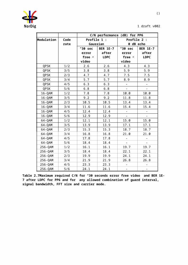
106 (457)
NorDig Unified Test plan, ver 2.6.0
Channel A, f = 474 MHz Channel B, f = 690 MHz
Testpoint
Initial signal level
[dBm]
Initial CNR[dB]
Additional BER Impair-
ment
Initial signal level
[dBm]
Initial CNR[dB]
Additional BER Impairment
RequiredΔS[%]
RequiredΔQ[%]
Receiverchannelchoice
Expectedchannelchoice
ResultOK/NOK
Reference condi-tions in flowchart
[1] Annex D
1 -60 no AWGN None -60 no AWGN None <10 <10 A or B 1,2,3,5,6 or 7
2 -50 no AWGN None -65 no AWGN None >10 <20 A 1 or 8
3 -65 no AWGN None -50 no AWGN None >10 <20 B 4 or 5
4 -61 CNR@QMP2+1dB None -60 CNR@QMP2+0.5dB None <10 <20 A 3
5 -60 CNR@QMP2+0.5dB None -61 CNR@QMP2+1dB None <10 <20 B 7
6 -61 no AWGN None -60 CNR@QMP2+1dB None <10 >20 A 2
7 -60 CNR@QMP2+1dB None -61 no AWGN None <10 >20 B 6
8 -50 no AWGN None -65 CNR@QMP2+1dB None >10 >20 A 1
9 -65 CNR@QMP2+1dB None -50 no AWGN None >10 >20 B 5
10 -50 no AWGN A BER>B BER -65 no AWGN A BER>B BER >10 <20 A 8
11 -65 no AWGN A BER<B BER -50 no AWGN A BER<B BER >10 <20 B 4
12 -60 no AWGN A BER<B BER -60 no AWGN A BER<B BER <10 >20 A 1 or 2
13 -60 no AWGN A BER>B BER -60 no AWGN A BER>B BER <10 >20 B 5 or 6
Table 20 Measurement record 2 for test Task 3:10.

107 (457)
NorDig Unified Test plan, ver 2.6.0
Test Case Task 3:11 Tuning/Scanning: Automatic channel search for different service bouquets
Section NorDig Unified 3.4.4.4Requirement The IRD shall provide an automatic search that finds all of the multiplexes and
services in the whole (supported) frequency range, see NorDig specification. The logic of the automatic search function shall be as follows:
If any services are detected during the automatic search the current service list shall be replaced by the new service list.
If no services are detected during the automatic search the current service list shall be kept or deleted.
The IRD shall only display a service once in the service list (i.e. avoiding duplicate of the same services), even if the same service (same triplet original_network_id, transport_stream_id and service_id) is received from multiple transmitters. If the same service can be received from several transmitters, the one with best reception quality shall be selected. The criteria for selection of the best received service (i.e. best reception quality) shall be based on the combination of the signal strength and signal quality according to NorDig Specification.
IRD profile(s) Basic, IRD, DVB-TTest procedure Purpose of test:
To verify the best service selection in automatic channel search when the content of the transport streams are different on several transmitters.
Equipment:
Channel XTS source #1ONID=8945
Network ID=1000Network Name=Net1
TSID=100Services
Channel YTS source #2ONID=8945
Network ID=2000Network Name=Net2
TSID=100Services
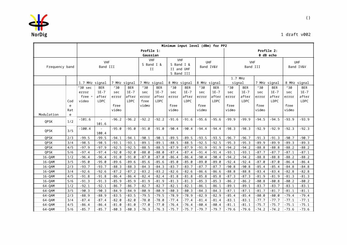
108 (457)
NorDig Unified Test plan, ver 2.6.0
Name SID Logic Ch NoS1 1 1S2 2 2S3 3 3S4 4 4
Name SID Logic Ch NoS1 1 1S5 5 2S6 6 6
The TS configuration idea in this test is that on terrestrial network there is possiblity to receive several transmitters simultaneously. These transmitters can have partially same content (nationwide services) and partially different content (regionwide services). ). It is the ON_id, TS_id and Service_id which define a service unique. The Network_id can be analysed to distinguish the differenciens in the TS. Therefore, it is important that the receiver can in automatic channel search choose the services which have the best reception quality and even find the regionwide services.
Channels x and y shall not be equal.
Test procedure:
This test procedure tests combination of the signal level and reception quality.
1. Configure transport streams and setup the instruments. Use DVB-T mode 8k 64QAM R=2/3 /Tu=1/8.
2. Set the signal level of the carrier CH x to a signal level which is about 5dB higher than the signal level of the carrier CH y. Both signal levels shall correspond good reception quality (no errors in decoded video).
3. Add noise on carrier CH x to a level that the QMP1 is fulfilled. 4. Perform automatic channel search. The logic of the automatic search function
shall be as follows:If any services are detected during the automatic search the current service list shall be replaced by the new service list.
If no services are detected during the automatic search the current service list shall be kept or deleted.
5. Check that channel list has services configured in transport streams.
After performing the test the channel list shall be as below:
Position Service Channel1 S1 Y2 S5/S2 * Y/X3 S3 X4 S4 X6 S6 Y7 S2/S5 * X/Y
*) Note that order of the services S2 and S5 on the channel list can be chosen by the manufacture. It’s highly recommended that the S5 (service without visible errors) is stored in position 2 and the S2 (service with visible errors) is stored in position 7. And generally it is recommended that service detected by the receiver as “better” service is stored in that position which is signalled in Logic Channel No and the other services with same Logic Ch No stored later in the list).
Expected result:All the tests are OK.
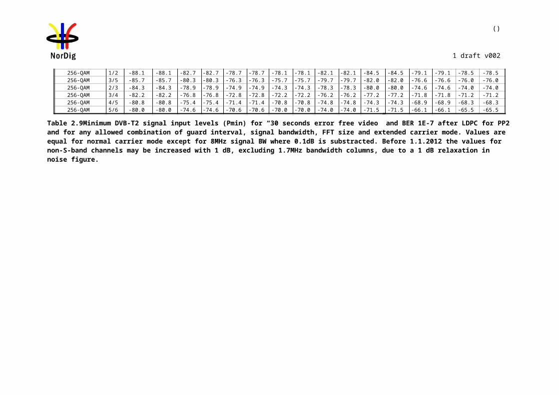
109 (457)
NorDig Unified Test plan, ver 2.6.0
Test result(s) Measurement record:
Requirement Result OK or NOK
After automatic channel search the channel lists does not contain duplicated services.The channel list is as defined in test procedure.
Conformity OK Fault Major Minor, define fail reason in commentsComments If possible describe if fault can be fixed with software update: YES NO
Describe more specific faults and/or other information
Date Sign
Test Case Task 3:12 Tuning/Scanning Procedures: Manual Channel Search
Section NorDig Unified 3.4.4.5Requirement In addition to the automatic search, it shall be possible to perform a manual search
where the channel id(or frequency) is entered by the end user. The IRD shall tune to this channel, search all available DVB-Tmodes, add all new services and replace existing equal services2 (same triplet original_network_id,transport_stream_id and service_id) in the service list (without considering any quality criteria).
IRD profile(s) Basic, IRD, DVB-TTest procedure Purpose of test:
To verify the functionality of the manual channel search.
Equipment:
Channel XTS source #1ONID=8945
Channel YTS source #2ONID=8945
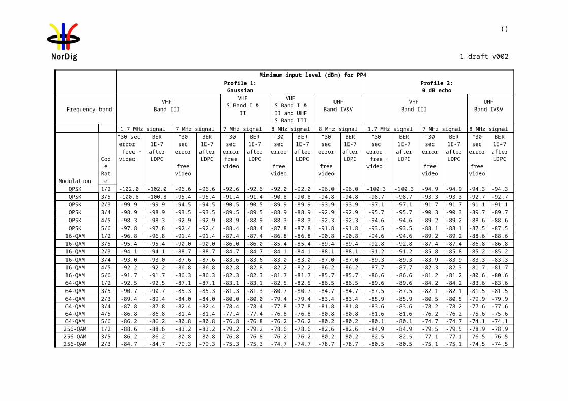
110 (457)
NorDig Unified Test plan, ver 2.6.0
Network ID=1000Network Name=Net1
TSID=100Services
Name SID Logic Ch NoS1 1 1S2 2
2S3 3
3S4 4
4
Network ID=2000Network Name=Net2
TSID=100Services
Name SID Logic Ch NoS1 1 1S5 5 2S6 6 6
The TS configuration idea in this test is that on terrestrial network there is possiblity to receive several transmitters simultaneously. These transmitters can have partially same content (nationwide services) and partially different content (regionwide services). It is the ON_id, TS_id and Service_id which define a service unique. The Network_id can be analysed to distinguish the differenciens in the TS.Furthermore, regional services may have same LCN which results to a conflict.Finally,it is important that user can force the receive to search all services within TS by selecting the channel number and install services from that TS on channel list without any quality criteria.
Test procedure:1. Configure transport streams and setup the instruments. 2. Check that channel list is empty. If it is not empty delete all services.3. Attenuate the carrier on CH x to a signal level that it is not possible to receive.4. Perform automatic channel search.5. Check that the services S1, S5 and S6 on channel list are from carrier on CH y
by attenuating the carrier on CH y. If the received channel is correct the services S1, S5 and S6 shall be frozen when the signal level is too low. Restore the attenuation level back to same level it was before you started to change it.
6. Decrease the attenuation of the carrier on CH x to a signal level that the carrier is possible to be received. Add noise on carrier CH x to a level that QMP1 is fulfilled.
7. Perform manual channel search. Check that the carrier, which is wanted to be searched, is given in channel number format.
8. Fill in the measurement record.9. Check that services S1, S2, S3 and S4 on channel list are from carrier on CH x
by attenuating the carrier on CH x. If the received channel is correct the services S1, S2, S3 and S4 shall be frozen when the signal level is too low. Restore the attenuation level back to same level it was before you started to change it.
10. Check that service S1 is not listed twice on channel list.
The channel list shall look like this after performing this procedure:
Position Service Channel1 S1 X2 S2/S5 * X/Y3 S3 X4 S4 X6 S6 Y7 S5/S2 * Y/X
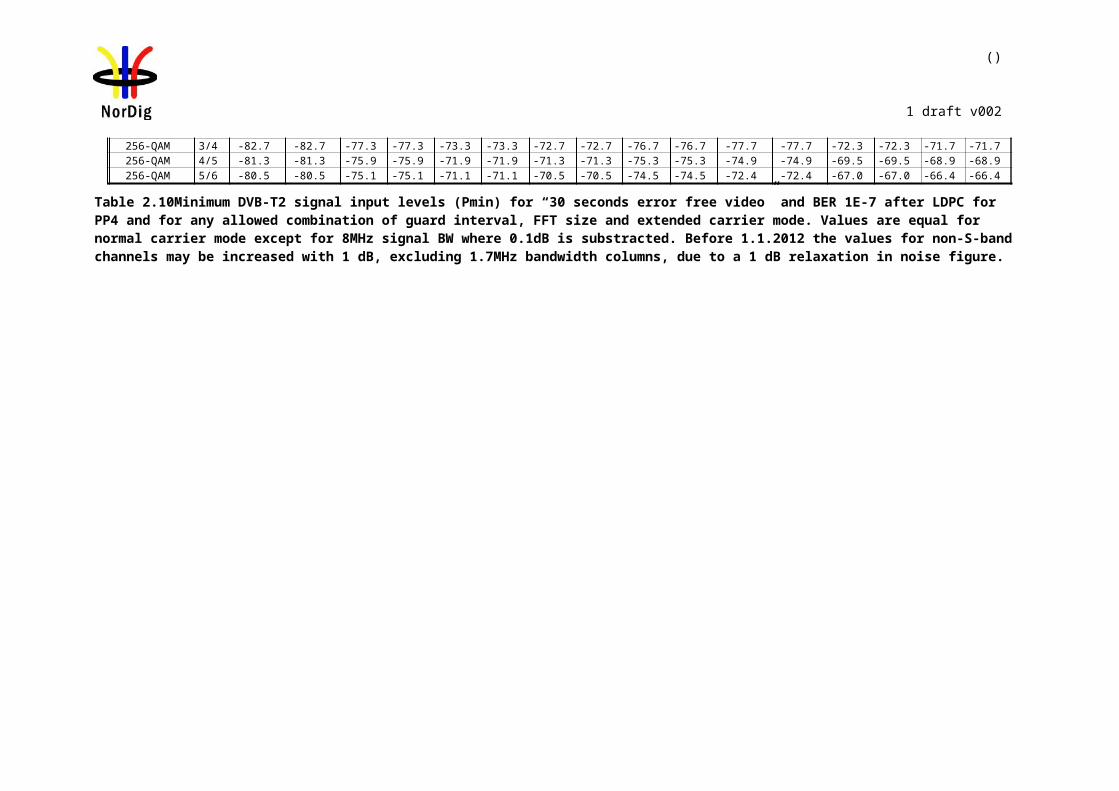
111 (457)
NorDig Unified Test plan, ver 2.6.0
*) Note that order of the services S2 and S5 can be chosen by the manufacture.. It is highly recommended thatthe services found in thelast manual channel search are stored in the service list according to their signallation. In terrestrial networks in a case where received services have equal ON_id, TS_id and LCN, but Network_id and Service_id differ most probably means regional variations of the same service. In that case it is highly recommended to move already stored service to an other position in the channel list and store the service found in the last manual channel search to position signaled in the LCN.
Expected result:All test results shall be OK.
Test result(s) Measurement record:
Requirement Result OK or NOKManual channel search can be performed successfully by only entering channel number The channel list is as defined in test procedureService S1 in only listed once on the channel list
Conformity OK Fault Major Minor, define fail reason in commentsComments If possible describe if fault can be fixed with software update: YES NO
Describe more specific faults and/or other information
Date Sign
Test Case Task 3:13 Verification of Signal Strength Indicator (SSI)
Section NorDig Unified 3.4.4.6Requirement The NorDig IRD shall be provided with a signal strength indicator (SSI). The value for
the SSI shall be referred to the IRD RF signal input.
The NorDig IRD shall be able to determine signal strength within a range starting from 15 dB lower than the reference signal level defined in NorDig Specification and up to 35dB above that value or maximum signal input level defined in NorDig Specification.
The absolute accuracy shall be ±5 dB at RF signal input levels -80 dBm to -60 dBm and ±7 dB for RF signal input levels higher than -60 dBm.
The relative accuracy should be ±3 dB between center frequencies within one frequency band, e.g. VHF Band III or UHF Band IV/V, supported by the receiver.
Signal strength indicator shall have a relative numerical value within a range from 0% to 100% and with a resolution of 1%.
The signal strength indicator shall be updated regularly once per second.
IRD profile(s) Basic, IRD, DVB-T
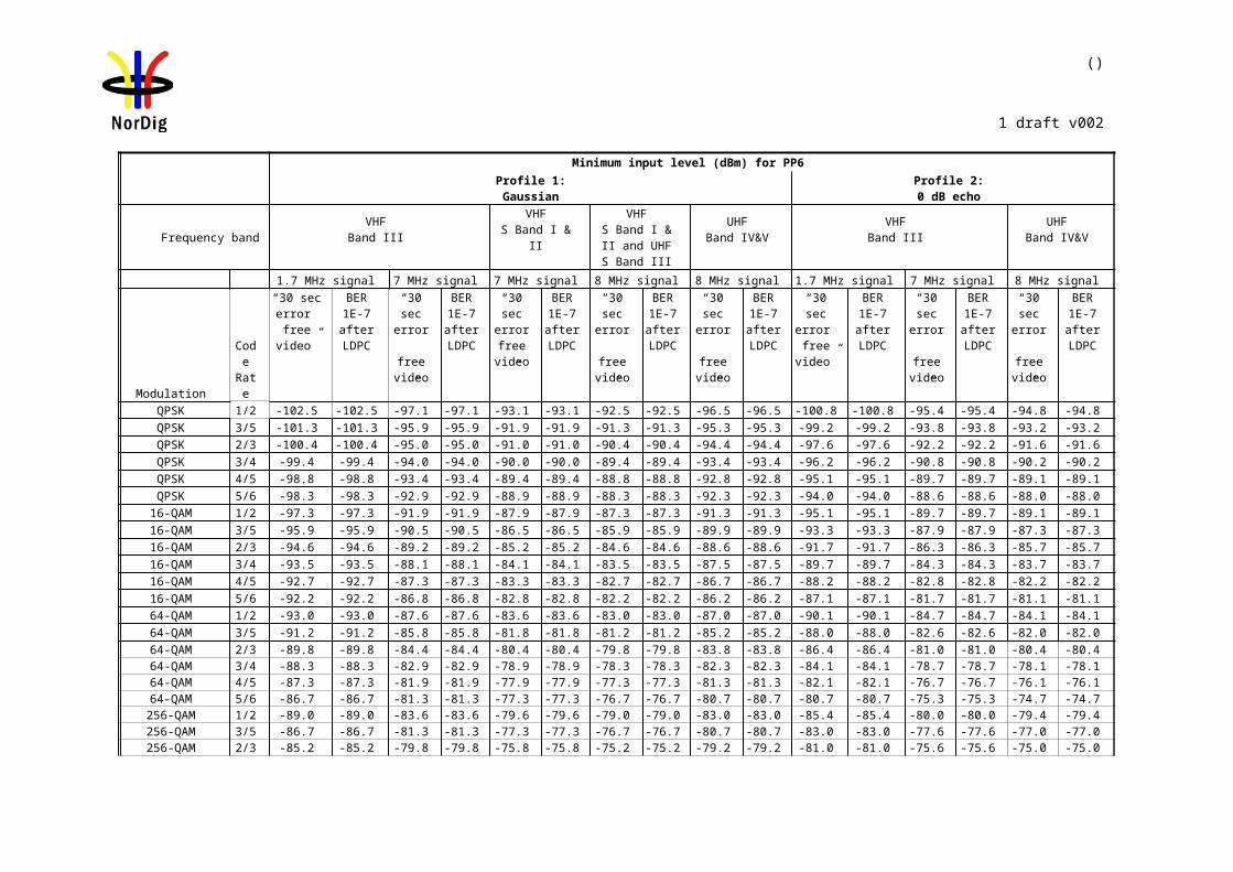
112 (457)
NorDig Unified Test plan, ver 2.6.0
Test procedure Purpose of test:To verify the correct functionality of the signal strength indicator.
Equipment:
Gaussian channel profile used i.e. no need for fading simulator.
In this test, the signal input level Pinput level at the RF input must be known.
The test procedure assumes that the Preceiver is not displayed by the receiver. If the Preceiver is displayed by the receiver this test procedure can be simplified.
Test procedure:
Verify SSI values:
1. Set-up the test system2. Determine the attenuation of the test system so that the signal input level at the
receiver input is known in the measured frequencies.3. Use the following DVB-T mode {8K, 64QAM, R=2/3, /TU=1/8}and signal
bandwidth of 8MHz. 4. Set the up-converter to frequency 474MHz (K21).5. Set the signal level into the receiver according to measurement record 1.6. Do the channel search.7. Fill in the SSI value displayed by the receiver in the measurement record 1. 8. SSImin and SSImax defines the allowed range of the displayed value. 9. Fill in the measurement record 1 OK or NOK depending of the displayed SSI
value.10. Measure rest of the frequencies and DVB-T modes.11. Fill in the measurement record 1.
Verify the relative error:
1. Convert the displayed SSI values to Preceiver [dBm] values. Select the correct formula for calculating Preceiver according to the displayed SSI value as shown below:
Preceiver = (3/2) * (SSI - 90) + 20 + Preference if 90 ≤ SSI < 100Preceiver = (1/4) * (SSI - 10) + Preference if 10 ≤ SSI < 90Preceiver = (3/2) * SSI - 15 + Preference if 0 ≤ SSI < 10
2. Fill in the dBm values in the measurement record 2 for corresponding signal input level.
3. Calculate the average value of the Preceiver values in three frequencies within a frequency band.
4. Verify the calculated Preceiver [dBm] values are within ±3 dB from the average value.
5. Fill in the measurement record 2 OK or NOK
Expected result:
DVB-Treceiver
DVB-TExciter
TSSource Monitor
PinputPreceiver
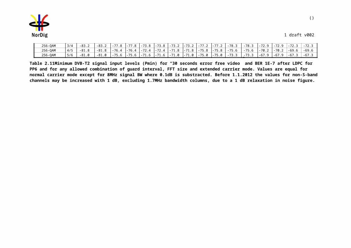
113 (457)
NorDig Unified Test plan, ver 2.6.0
All the measurements shall be OK.
The signal strength indicator value is updated regurlaly once per second.
Test result(s)Measurement record 1:
8k 64QAM R2/3 G1/8 8MHz,Preference=-80dBm, f=666MHzPinput level [dBm] SSI [%] SSImin [%] SSImax [%] NOK or OK
-40 99 100-50 92 100-60 70 93-70 30 70-80 7 30-95 0 5
8k 64QAM R2/3 G1/8 8MHz,Preference=-80dBm, f=474MHzPinput level [dBm] SSI [%] SSImin [%] SSImax [%] NOK or OK
-40 99 100-50 92 100-60 70 93-70 30 70-80 7 30-95 0 5
8k 64QAM R2/3 G1/8 8MHz,Preference=-80dBm, f=786MHzPinput level [dBm] SSI [%] SSImin [%] SSImax [%] NOK or OK
-40 99 100-50 92 100-60 70 93-70 30 70-80 7 30-95 0 5
8k 64QAM R2/3 G1/8 7MHz,Preference=-80dBm, f=177.5MHzPinput level [dBm] SSI [%] SSImin [%] SSImax [%] NOK or OK
-40 99 100-50 92 100-60 70 93-70 30 70-80 7 30-95 0 5
8k 64QAM R2/3 G1/8 7MHz,Preference=-80dBm, f=198.5MHzPinput level
[dBm]SSI [%] SSImin
[%]SSImax
[%]NOK or OK
-40 99 100-50 92 100-60 70 93-70 30 70-80 7 30
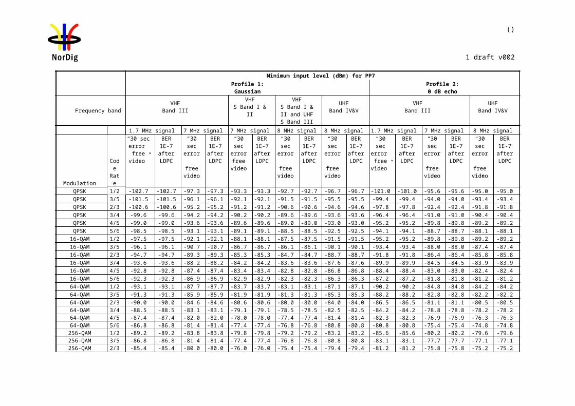
114 (457)
NorDig Unified Test plan, ver 2.6.0
-95 0 5
8k 64QAM R2/3 G1/8 7MHz,Preference=-80dBm, f=226.5MHzPinput level [dBm] SSI [%] SSImin [%] SSImax [%] NOK or OK
-40 99 100-50 92 100-60 70 93-70 30 70-80 7 30-95 0 5
8k 64QAM R3/4 G1/4 8MHz,Preference=-78dBm, f=666MHzPinput level [dBm] SSI [%] SSImin [%] SSImax [%] NOK or OK
-40 97 100-50 91 100-60 62 92-70 22 62-80 5 22-95 0 3
Measurement record 2:
Pinput level [dBm]
Preceiver [dBm] @474MHz
Preceiver [dBm]@666MHz
Preceiver [dBm] @786MHz
Average NOKor
OK-40-50-60-70-80-95
Pinput level [dBm]
Preceiver
[dBm] @177.5MHz
Preceiver
[dBm] @198.5MHz
Preceiver
[dBm] @226.5MHz
Average NOKor
OK-40-50-60-70-80-95
Conformity OK Fault Major Minor, define fail reason in commentsComments If possible describe if fault can be fixed with software update: YES NO
Describe more specific faults and/or other information
Date Sign
Test Case Task 3:14 Verification of Signal Quality Indicator (SQI)

115 (457)
NorDig Unified Test plan, ver 2.6.0
Section NorDig Unified 3.4.4.7Requirement The NorDig IRD shall (1) be provided with a signal quality indicator (SQI). The value for
the SQI shall be referred to the IRD RF signal input.
The absolute accuracy of the C/N value shall be of ±1dB for C/N values of 17 dB to 27 dB at the IRD RF signal input.
The signal quality indicator shall have a relative numerical value within a range from 0% to 100% and with a resolution of 1%.
The integration time for the signal quality shall be over a period of 5 seconds.
The signal quality indicator shall be updated regularly once per second.
IRD profile(s) Basic, IRD, DVB-TTest procedure Purpose of test:
To verify the correct functionality of the signal quality indicator.
Equipment:
Gaussian channel profile used i.e. no need for fading simulator.
C/Ninput refers to generated DVB-T signal C/N at receiver input.
C/Nreceiver refers to C/N determined by the receiver under test.
C/Nrel = C/Ninput – C/NNorDigP1
C/NNorDigP1 refers to table 3.10 at [1].
First we need to define the required C/Ninput for the QMP2. After that we know what is the expected rescale of BER before RSThe slope of the curve for BER before RS as a function of the required C/Ninput should be equal independently of the receiver. Using that knowledge SQImin and SQImax can be calculated.
Test procedure:
1. Set up the test instruments2. Use the following DVB-T mode {8K, 64QAM, R=2/3, /TU=1/8} and signal
bandwidth 8MHz.3. Set the up-converter to frequency 666MHz (K45).4. Do the channel search.5. Determine the lowest required C/N by adjusting the C/Ninput until the quality
measurement procedure 2 error free video is fulfilled.6. Fill in the measurement record 1 the C/Ninput value defined as C/Nreceiver. Later in
this test procedure the value C/Nreceiver is used for rescaling of the BER_SQImin and BER_SQImax values.
DVB-Treceiver
DVB-TExciter
TSSource Monitor
C/NinputC/Nreceiver
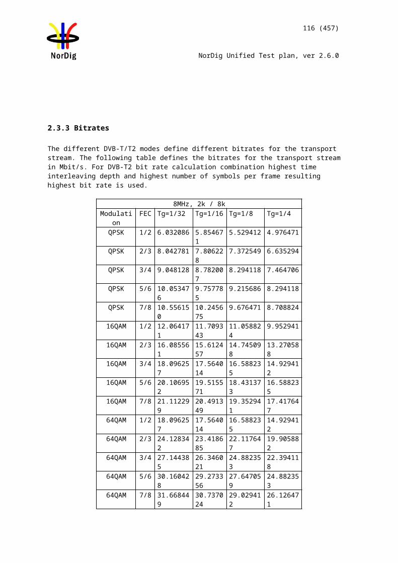
116 (457)
NorDig Unified Test plan, ver 2.6.0
7. Decrease the C/Ninput in 1dB step starting from highest value in measurement record 2.
8. Fill in the displayed SQI in the measurement record 2.9. Repeat the test for the DVB-T mode {8K, 64QAM, R=3/4, /TU=1/4} and signal
bandwidth 8MHz.10. Do the calculations in the rest of the test procedure.
Calculation for minimum SQI value:
11. Calculate C/Nrel_error_min for all C/Ninput values using formula C/Nrel_error_min = C/Nrel – 1
12. Calculate CNR_SQImin for all C/Ninput values using formulaCNR_SQImin = 0, if C/Nrel_error_min < -7 dBCNR_SQImin = [(C/Nrel_error_min – 3)/10]+1, if -7 dB ≤ C/Nrel_error_min < 3 dBCNR_SQImin = 1, if C/Nrel_error_min ≥ 3 dB
13. Calculate BER_SQImin for all C/Ninput values using formulaBER_SQImin =19.0 * [C/Nrel_error_min –(C/Nreceiver - X) + 3.6], where X = 16.2 (64QAM R2/3) X = 17.4 (64QAM R3/4)if resulted BER_SQImin < 20 then set BER_SQImin = 0if resulted BER_SQImin > 100 then set BER_SQImin = 100.
14. Calculate SQImin using formulaSQImin = CNR_SQImin * BER_SQImin
15. Fill in the SQImin values in the measurement procedure 2.
Calculation for maximum SQI value:16. Calculate C/Nrel_error_max for all C/Ninput values using formula
C/Nrel_error_max = C/Nrel + 1 17. Calculate CNR_SQImax for all C/Ninput values using formula
CNR_SQImax = 0, if C/Nrel_error_max < -7 dBCNR_SQImax = [(C/Nrel_error_max – 3)/10]+1, if -7 dB ≤ C/Nrel_error_max < 3 dBCNR_SQImax = 1, if C/Nrel_error_max ≥ 3 dB
18. Calculate BER_SQImax for all C/Ninput values using formulaBER_SQImax =19.0 * [C/Nrel_error_max –(C/Nreceiver – X) + 3.6], where X = 16.2 (64QAM R2/3) X = 17.4 (64QAM R3/4)if resulted BER_SQImax < 20 then set BER_SQImax = 0if resulted BER_SQImax > 100 then set BER_SQImax = 100.
19. Calculate SQImax using formulaSQImax = CNR_SQImax * BER_SQImax
20. Fill in the SQImax values in the measurement procedure 2.
Expected result:
All the test result are OK.The signal quality indicator is updated regurlaly once per second.
Test result(s) Measurement record 1:
DVB-T mode Required C/Nreceiver [dB](60 sec error free video)
8k 64QAM R2/3 G1/8 8MHz8k 64QAM R3/4 G1/4 8MHz
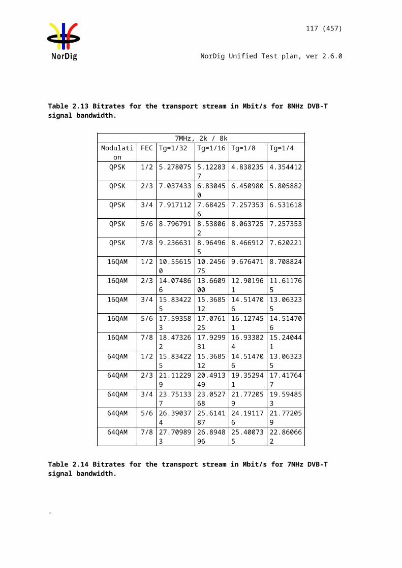
117 (457)
NorDig Unified Test plan, ver 2.6.0
Measurement record 2:
8k 64QAM R2/3 G1/8 8MHz, C/NNorDigP1 = 18.7dB
C/Ninput SQI[%] SQImin[%] SQImax[%] NOK or OK2726252423222120191817
8k 64QAM R3/4 G1/4 8MHz, C/NNorDigP1 = 20.2dB
C/Ninput SQI[%] SQImin[%] SQImax[%] NOK or OK2726252423222120191817
Example for calculating SQImin and SQImax values for 64QAM R2/3 when C/Nreceiver = 15.0dB at QMP2 resulting to C/Nreceiver – X = -1.2dB where X = 16.2:
CNRreceiver @QMP2= 15(C/Nreceiver-16.2) @QMP2= -1,264QAM R2/3 C/NNorDigP1= 18,7
C/ Ninput C/Nrel
C/N errorMin
C/Nrel errorMin
CNR_ SQIMin
BER_ SQIMin
C/N errorMax
C/Nrel errorMax
CNR_ SQIMax
BER_ SQIMax
SQIMin
SQIMax
SQImeasured 64QAM
R2/ 3OK or NOK
15 -3,7 -1 -4,7 0,23 0 1 -2,7 0,43 40 0 1816 -2,7 -1 -3,7 0,33 21 1 -1,7 0,53 59 6 32
16,2 -2,5 -1 -3,5 0,35 25 1 -1,5 0,55 63 8 3517 -1,7 -1 -2,7 0,43 40 1 -0,7 0,63 78 17 5018 -0,7 -1 -1,7 0,53 59 1 0,3 0,73 97 31 7119 0,3 -1 -0,7 0,63 78 1 1,3 0,83 100 49 8320 1,3 -1 0,3 0,73 97 1 2,3 0,93 100 70 9321 2,3 -1 1,3 0,83 100 1 3,3 1,00 100 83 10022 3,3 -1 2,3 0,93 100 1 4,3 1,00 100 93 10023 4,3 -1 3,3 1,00 100 1 5,3 1,00 100 100 10024 5,3 -1 4,3 1,00 100 1 6,3 1,00 100 100 10025 6,3 -1 5,3 1,00 100 1 7,3 1,00 100 100 10026 7,3 -1 6,3 1,00 100 1 8,3 1,00 100 100 10027 8,3 -1 7,3 1,00 100 1 9,3 1,00 100 100 100
Conformity OK Fault Major Minor, define fail reason in commentsComments If possible describe if fault can be fixed with software update: YES NO
Describe more specific faults and/or other information
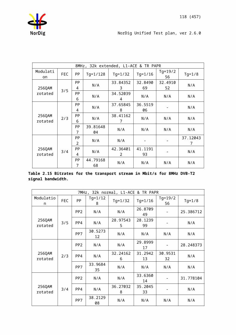
118 (457)
NorDig Unified Test plan, ver 2.6.0
Date Sign
Test Case Task 3:15 Changes In Modulation Parameters
Section NorDig Unified 3.4.5Requirement The terrestrial NorDig IRD should recover from changes in modulation parameters at
the end of a superframe without a break in the received DVB-T signal and output an error free TS. This should take less than one second for any change. The Nordig IRD should be able to detect a change of modulation parameters signalled in the TPS data of the DVB-T signal, in order to reduce the recovery time.
The terrestrial NorDig IRD should recover from changes in modulation parameters occurring at any time followed by a break in the received DVB-T signal and output an error free TS. This should take less than four seconds for any change.
IRD profile(s) Basic, IRD, DVB-TTest procedure Purpose of test:
To verify that receiver can recover from changes in modulation parameter occurring at any time followed by a break in the received DVB-T signal and output an error free TS. .
Equipment:
The DVB-T modulator shall have a bitrate adaptation to test this test, or, alternatively the TS source shall have capability to change the output transport stream bitrate to correspond the DVB-T mode. See bitrates in chapter 2.3.3.
Test procedure:
1. Set up the instruments.2. Use frequency 666 MHz (K45). 3. Set the RF input level to receiver to –50dBm.4. Set up DVB-T mode 8k 64QAM R3/4 G1/4 and signal bandwidth 8 MHz in
DVB-T modulator.5. Verify that the switch is closed.6. Check picture quality using the quality measurement procedure 1 (QMP1).7. Open the switch to break the received RF signal8. Change DVB-T mode to the next mode in the measurement record9. Wait for the DVB-T modulator output to become valid and stable with this new
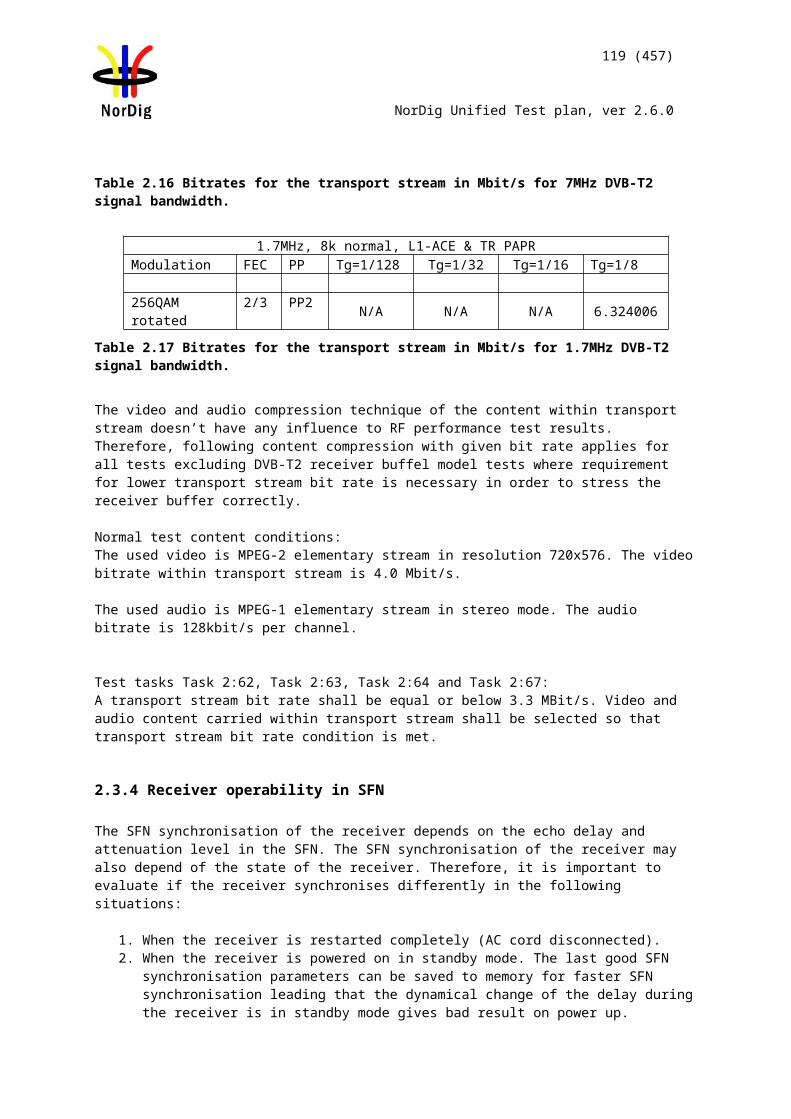
119 (457)
NorDig Unified Test plan, ver 2.6.0
mode (this time is modulator specific)10. Close the switch to enable the RF signal to the receiver and record the time
taken to achieve QMP111. Fill in the measurement record.12. Repeat steps 7-11 for the rest of the DVB-T modes defined in the measurement
record.
Expected result:The receiver can recover from changes in modulation parameter occurring at any time followed by a break in the received DVB-T signal and output an error free TS within 4 seconds (excluding modulator stabilization time) without requiring a channel scan.
Test result(s) Measurement record:
Mode NOK or OK8k 64QAM R3/4 G1/48k 64QAM R2/3 G1/48k 64QAM R2/3 G1/88k 16QAM R2/3 G1/88k QPSK R1/2 G1/82k QPSK R1/2 G1/162k 16QAM R2/3 G1/32
Conformity OK Fault Major Minor, define fail reason in commentsComments If possible describe if fault can be fixed with software update: YES NO
Describe more specific faults and/or other information
Date Sign
Test Case Task 3:16 RF input connector
Section NorDig Unified 3.4.6Requirement The NorDig IRD shall have one input tuner connector, type: IEC female in accordance
with IEC 61169-2, part 2 [28]. The input impedance shall be 75 ohm.
IRD profile(s) Basic, IRD, DVB-TTest procedure Purpose of test:
To verify that the receiver has a correct input connector for the reception of the DVB-T signals.
Equipment:
No special equipment is required.
Test procedure:
Verify that the RF input connector is accordance the specification IEC 61169-2. (With other words the connector is similar as RF input connector used in TV sets RF input).
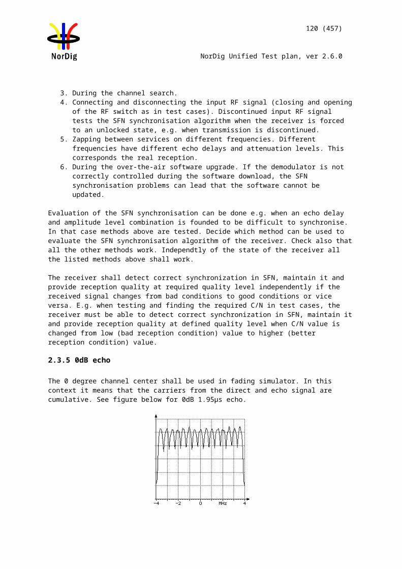
120 (457)
NorDig Unified Test plan, ver 2.6.0
Verify in the manufacturer’s technical specification that the input impedance of the RF input is 75 ohm.
Expected result:
RF input connector is as defined in specification IEC 61169-2 and the input impedance is 75ohm.
Test result(s) The manufacturer describes his specific setup for the test
Conformity OK Fault Major Minor, define fail reason in commentsComments If possible describe if fault can be fixed with software update: YES NO
Describe more specific faults and/or other information
Date Sign
Test Case Task 3:17 RF output connector
Section NorDig Unified 3.4.7
Requirement
For a NorDig IRDs equipped with a RF bypass (RF in - RF out), the connector shall be of type: IEC male in accordance with IEC 61169, part 2 [28]. The frequency range for the RF bypass should be from 47 MHz to 862 MHz and the RF bypass gain should be from –1 dB to +3 dB.
The RF signals should be bypassed from RFin to RFout independently from the status of the NorDig IRD (operational or stand by), so that connected equipment (e.g. TV set) can operate even if the NorDig IRD is in stand by.
IRD profile(s) Basic, IRD, DVB-TTest procedure Purpose of test:
To check that the receiver has a correct output connector for the loop through of the RF signals.To test the attenuation/gain of the RF loop through for standby and oprational modes.
Equipment:
Test procedure:
1. Connect signal generator to receiver RF input and spectrum analyser to RF output (may need DC block).
2. Set the input level to the receiver –50dBm. Use CW. 3. Sweep the frequency of the signal generator from 47 MHz to 869 MHz.4. Measure the attenuation of the loop thoough over the frequency range.5. Repeat the test for the standby mode.
Verify that the RF output connector is accordance the specification IEC 61169-2.
Signal generator STB Spectrum analyzer or power meter
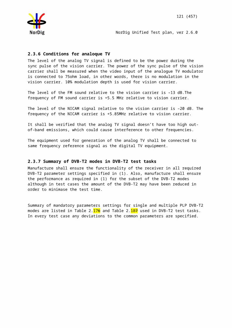
121 (457)
NorDig Unified Test plan, ver 2.6.0
Expected result:
RF output connector is as defined in specification IEC 61169, the attenuation of the loop through shall not be too low or high and the loopthrough works in operational and standby mode.
Test result(s)Conformity OK Fault Major Minor, define fail reason in commentsComments If possible describe if fault can be fixed with software update: YES NO
Describe more specific faults and/or other information
Date Sign
Test Case Task 3:18 Performance: BER vs C/N verification
Section NorDig Unified 3.4.10.2Requirement Verify the internal BER measurement of the NorDig IRD for objective measurements
(QMP3).IRD profile(s) Basic, IRD, DVB-T
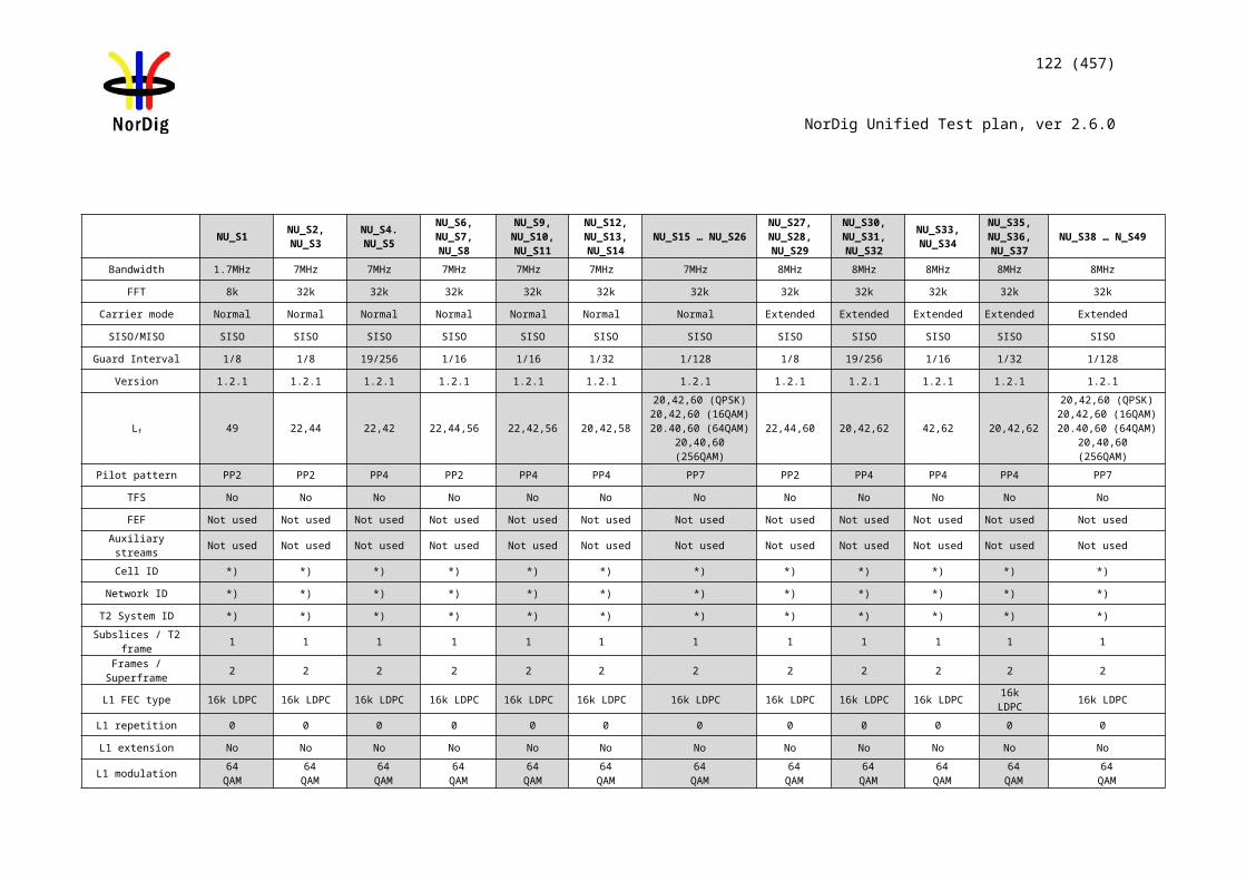
122 (457)
NorDig Unified Test plan, ver 2.6.0
Test procedure Purpose of test:To check that the internal BER value measured by the receiver to reference BER value in a function of C/N on Gaussian channel is correct.
Equipment:
Reference BER in a function of the C/N on Gaussian channel.
Test procedure:
1. Setup the instruments.2. Use channel 45 and DVB-T mode 8k 64QAM R3/4 G1/4. Set the RF input
level to –50dBm.3. Use the quality measurement procedure 2.4. Compare the BER measured by the receiver to reference BER in a function of
the C/N measurement on Gaussian channel. 5. Fill in the BER value in measurement record.6. Adjust the required C/N that it corresponds BER 2E-4 after viterbi. 7. Decrease the required C/N by 1dB. Check that it corresponds approximately
BER 2E-3 after viterbi and QMP1.
Expected result:The measured BER in a function of required C/N shall have the same slope as with the reference BER in a function of required C/N.
BER vs C/N on Gaussian channel, 8k 64QAM R3/4 G1/4
1,0E-06
1,0E-05
1,0E-04
1,0E-03
1,0E-02
19,0 20,0 21,0 22,0 23,0
C/N [dB]
BER
aft
er V
iterb
i
Reference receiver
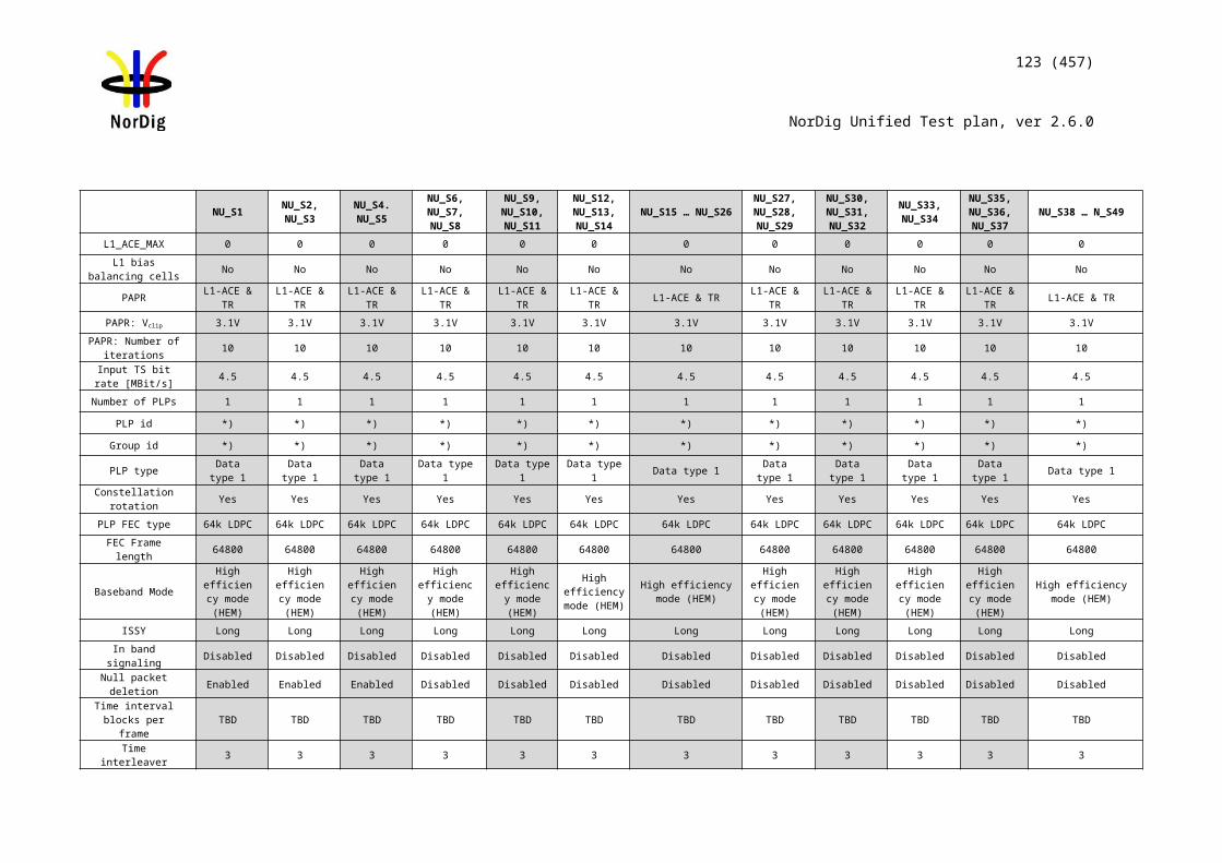
123 (457)
NorDig Unified Test plan, ver 2.6.0
The decrease of the required C/N corresponding BER 2E-4 after Viterbi by 1dB shall result approximately to BER 2E-3 after Viterbi corresponding QMP1.
Test result(s) Measurement record:
C/N Reference BER
Measured BER
18.0 -18.2 -18.4 -18.6 -18.8 -19.0 -19.2 -19.4 -19.6 6.3E-420.0 3.0E-420.2 2.0E-420.6 9.3E-521.0 6.2E-521.6 1.3E-522.0 5.1E-622.6 1.7E-6
Conformity OK Fault Major Minor, define fail reason in commentsComments If possible describe if fault can be fixed with software update: YES NO
Describe more specific faults and/or other information
Date Sign
Test Case Task 3:19 Performance: C/N performance on Gaussian channel
Section NorDig Unified 3.4.10.3Requirement The NorDig IRD shall have a QEF performance for the C/N ratios given in Table 3.109,
or better performance.
IRD profile(s) Basic, IRD, DVB-TTest procedure Purpose of test:
To test the required C/N for quasi error free reception in Gaussian channel.
Equipment:
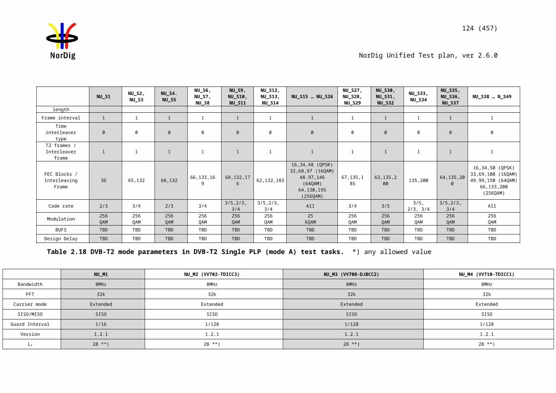
124 (457)
NorDig Unified Test plan, ver 2.6.0
Test procedure for Gaussian channel:
16. Set up the test instruments17. Use the following mode {8K, 64QAM, R=2/3, /TU=1/8}18. Set the up-converter to channel 2119. Measure the input level to the attenuator. 20. Determine the attenuation of the attenuator and the cables.21. Calculate the receiver input signal level and set it to –50dBm. 22. Use the value for the required C/N specified for the DVB-T mode in table
3.109.23. Do the channel search.24. Increase the C/N from low value to higher value until the quality measurement
procedure 2 (QMP2) fulfils.25. Fill in the measured value in dB in the measurement record. 26. Repeat the test for the rest of the frequencies, signal bandwidths and DVB-T
modes defined in the measurement record.
Expected result:
The required C/N for quasi error free reception in gaussian channel is less than specified in table 3.109.
Test result(s) Measurement record: See tables below.
Conformity OK Fault Major Minor, define fail reason in commentsComments If possible describe if fault can be fixed with software update: YES NO
Describe more specific faults and/or other information
Date Sign
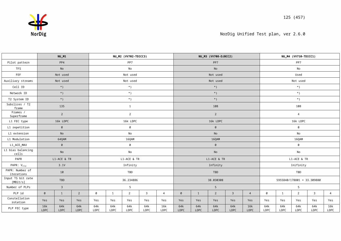
125 (457)
NorDig Unified Test plan, ver 2.6.0
Measurement record:Signal bandwidth 7 MHz 8 MHz
Centerfrequency [MHz] 177.5 198.5 226.5 474.0 522.0 570.0 618.0 666.0 714.0 762.0 810.0 858.0DVB-T mode / Channel Id K5 K8 K12 K21 K27 K33 K39 K45 K51 K57 K63 K69
8k QPSK R1/2 G1/48k QPSK R2/3 G1/48k QPSK R3/4 G1/48k QPSK R5/6 G1/48k QPSK R7/8 G1/4
8k 16QAM R1/2 G1/48k 16QAM R2/3 G1/48k 16QAM R3/4 G1/48k 16QAM R5/6 G1/48k 16QAM R7/8 G1/48k 64QAM R1/2 G1/48k 64QAM R2/3 G1/48k 64QAM R2/3 G1/88k 64QAM R3/4 G1/48k 64QAM R5/6 G1/48k 64QAM R7/8 G1/4
Table 1. Mandatory frequencies and signal bandwidths to support.
Signal bandwidth 8 MHzCenter frequency [MHz] 114.0 114.5 170.0 170.5 177.5 178.0 226.0 226.5 233.5 234.0 296.5 298.0 306.0 386.0 466.0
DVB-T mode / Channel Id D1 S2 D8 S10 K5 D9 D15 K12 S11 D16 S20 D24 S21 S31 S418k 64QAM R2/3 G1/88k 64QAM R3/4 G1/4
Table 2. Optional frequencies and signal bandwidths to support.
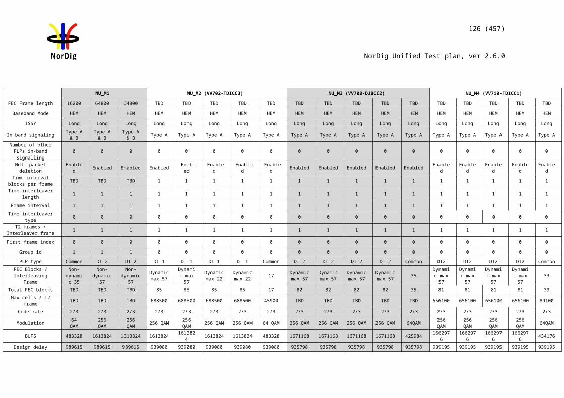
126 (457)
NorDig Unified Test plan, ver 2.6.0
Test Case Task 3:20 Performance: C/N performance on 0dB echo channel
Section NorDig Unified 3.4.10.3Requirement The NorDig IRD shall have a QEF performance for the C/N ratios given in Table 3.109,
or better performance.
IRD profile(s) Basic, IRD, DVB-TTest procedure Purpose of test:
To test the required C/N for quasi error free reception in 0 dB echo channel.
Equipment:
The 0 degree channel center shall be used in fading simulator (see 2.3.5 0dB echo).
Test procedure for 0 dB echo channel:
Check the different SFN synchronization issues from 2.3.4 Receiver operability in SFN.
1. Set up the test instruments2. Use the following mode {8K, 64QAM, R=2/3, /TU=1/8} and signal bandwidth
8MHz.3. Set the up-converter to frequency 666MHz (K45)4. Set the fading simulator to 0dB echo profile. (Delay 1.95us, 0 degree phase at
channel center and attenuation 0dB for the second path.)5. Measure the input level to the attenuator. 6. Determine the attenuation of the attenuator and the cables.7. Calculate the receiver input signal level and set it to –50dBm. 8. Increase the C/N from low value to higher value until the quality measurement
procedure 2 (QMP2) is fulfilled.9. Fill in the measured value in dB in the measurement record. 10. Verify also that the channel search founds the services at the measured C/N.11. Repeat the test for the mode {8K, 64QAM, R=3/4, /TU=1/4} and signal
bandwidth 8MHz.12. Repeat the test for rest of the DVB-T modes combinations with 8MHz signal
bandwidth in measurement record.13. Set the up-converter to frequency 198.5MHz (K8).14. Use the following mode {8K, 64QAM, R=2/3, /TU=1/8} and signal bandwidth
7MHz.15. Repeat the test for rest of the DVB-T mode combinations with 7MHz signal
bandwidth in measurement record.
(Measurement can be done by chancing the modulation/code rate first and after that
127 (457)
NorDig Unified Test plan, ver 2.6.0
echo delay depending of the measurement equipment).
Expected result:The required C/N for quasi error free reception in 0 dB echo channel is less than specified in table 3.109
Test result(s) Measurement record:
8MHz signal bandwidth at f=666MHzDVB-T mode Required C/N
(0dB 1.95µs)8k QPSK R1/2 G1/48k QPSK R2/3 G1/48k QPSK R3/4 G1/48k 16QAM R1/2 G1/48k 16QAM R2/3 G1/48k 16QAM R3/4 G1/48k 64QAM R1/2 G1/48k 64QAM R2/3 G1/88k 64QAM R2/3 G1/48k 64QAM R3/4 G1/4
Table 1. Required C/N for 0dB 1.95µs echo in signal bandwidth 8MHz.
7MHz signal bandwidth at f=198.5MHzDVB-T mode Required C/N
(0dB 1.95µs)8k QPSK R1/2 G1/48k QPSK R2/3 G1/48k QPSK R3/4 G1/48k 16QAM R1/2 G1/48k 16QAM R2/3 G1/48k 16QAM R3/4 G1/48k 64QAM R1/2 G1/48k 64QAM R2/3 G1/88k 64QAM R2/3 G1/48k 64QAM R3/4 G1/4
Table 2. Required C/N for 0dB 1.95µs echo in signal bandwidth 7MHz.
Conformity OK Fault Major Minor, define fail reason in commentsComments If possible describe if fault can be fixed with software update: YES NO
Describe more specific faults and/or other information
Date Sign
Test Case Task 3:21 Performance: Minimum receiver signal input levels on Gaussian channel
Section NorDig Unified 3.4.10.4Requirement The NorDig IRD shall have at least the performance for the signal input levels for the
supported frequency range and should have a performance which is one dB better than specified in Table 3.13
128 (457)
NorDig Unified Test plan, ver 2.6.0
IRD profile(s) Basic, IRD, DVB-TTest procedure Purpose of test:
To verify the sensitivity of the receiver on Gaussian channel over the supported frequency range. Equipment:
Be careful in impedance matching of cables, adapters and etc.
Test procedure for the sensitivity on the gaussian channel:
1. Set up the test instruments2. Use the following DVB-T mode {8K, 64QAM, R=2/3, /TU=1/8} and signal
bandwidth 8MHz.3. Set the up-converter to frequency 474MHz (K21).4. Measure the input level to the attenuator. 5. Determine the attenuation of the attenuator and the cables.6. Calculate the receiver input signal.7. Do the channel search.8. Increase the received input level from low value to higher value until the
quality measurement procedure 2 (QMP2) is fulfilled.9. Fill in the measured value in the measurement record. 10. Repeat the test for the rest of the frequencies, DVB-T modes and signal
bandwidths on measurement record.
Expected result:Sensitivity shall be equal or better for all measured frequencies (channels) and for all DVB-T modes and signal bandwidths as specified in Table 3.13.
Test result(s) Measurement record: See following page.
Conformity OK Fault Major Minor, define fail reason in commentsComments If possible describe if fault can be fixed with software update: YES NO
Describe more specific faults and/or other information
Date Sign
129 (457)
NorDig Unified Test plan, ver 2.6.0
Measurement records:Signal bandwidth 7 MHz 8 MHz
Center frequency [MHz] 177.5 198.5 226.5 474.0 522.0 570.0 618.0 666.0 714.0 762.0 810.0 858.0DVB-T mode / Channel Id K5 K8 K12 K21 K27 K33 K39 K45 K51 K57 K63 K69
8k QPSK R1/2 G1/48k QPSK R2/3 G1/48k QPSK R3/4 G1/48k QPSK R5/6 G1/48k QPSK R7/8 G1/4
8k 16QAM R1/2 G1/48k 16QAM R2/3 G1/48k 16QAM R3/4 G1/48k 16QAM R5/6 G1/48k 16QAM R7/8 G1/48k 64QAM R1/2 G1/48k 64QAM R2/3 G1/48k 64QAM R2/3 G1/88k 64QAM R3/4 G1/48k 64QAM R5/6 G1/48k 64QAM R7/8 G1/4
Table 1. Mandatory frequencies and signal bandwidths to support.
Signal bandwidth 8 MHzCenter frequency
[MHz]114.0 114.5 170.0 170.5 177.5 178.0 226.0 226.5 233.5 234.0 296.5 298.0 306.0 386.0 466.0
DVB-T mode / Channel Id
D1 S2 D8 S10 K5 D9 D15 K12 S11 D16 S20 D24 S21 S31 S41
8k 64QAM R2/3 G1/8
8k 64QAM R3/4 G1/4
Table 2. Optional frequencies and signal bandwidths to support.
Test Case Task 3:22 Performance: Minimum IRD Signal Input Levels on 0dB echo channel
Section NorDig Unified 3.4.10.4Requirement The NorDig IRD shall have at least the performance for the signal input level for the
supported frequency range and should have a performance which is 1dB better than specified in Table 3.13.
IRD profile(s) Basic, IRD, DVB-TTest procedure Purpose of test:
To verify the sensitivity of the receiver on frequency selective channel.
Equipment:
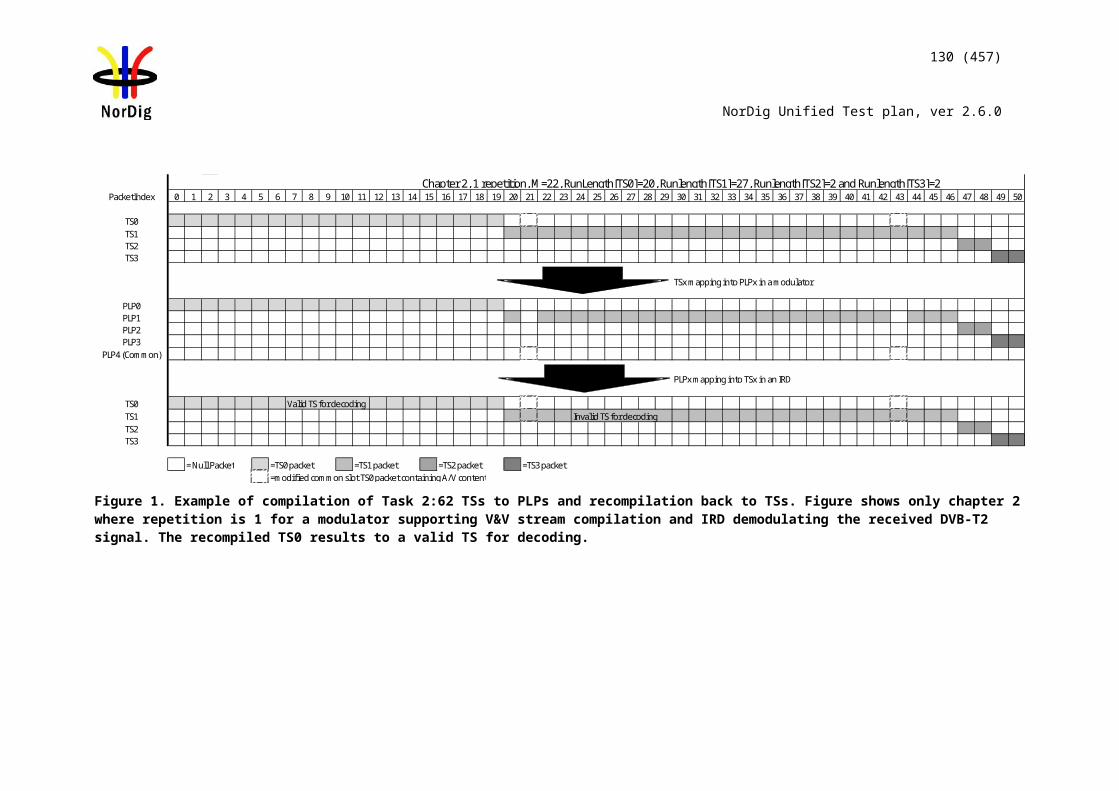
130 (457)
NorDig Unified Test plan, ver 2.6.0
The 0 degree channel center shall be used in fading simulator (see 2.3.4) 0dB echo.
Be careful in impedance matching of cables, adapters and etc.
The 0dB echo profile must be activated when measuring the power level of the signal.
Test procedure for the sensitivity on the frequency selective channel:
Check the different SFN synchronisation issues from 2.3.4 Receiver operability in SFN.
1. Set up the test instruments2. Use the following DVB-T mode {8K, 64QAM, R=2/3, /TU=1/8} and signal
bandwidth 8MHz.3. Set the up-converter to frequency 666.0 MHz (K45).4. Set the fading simulator to 0dB echo profile. (Delay 1.95us, 0 degree phase at
channel center and attenuation 0dB for the second path.)5. Determine the attenuation of the attenuator and the cables.6. Measure the input level to the attenuator.7. Calculate the receiver input signal level. 8. Increase the received input level from low value to higher value until the
quality measurement procedure 2 (QMP2) is fulfilled.9. Fill in the measured value in the measurement record.10. Verify that the channel search founds the services on measured minimum input
signal level.11. Repeat the test for the rest of the DVB-T modes on the measurement record. 12. Set the up-converter to frequency 198.5 MHz (K8) and signal bandwidth to
7MHz.13. Repeat the test for the rest of the DVB-T modes in the measurement record.
(Measurement can be done by chancing the modulation/code rate first and after that echo delay depending of the measurement equipment).
Expected result:
Required minimum signal level shall be equal or lower in dBm than specified in table 3.13on measured frequencies, DVB-T modes and signal bandwidths for all echo delays..
Test result(s) Measurement record:
F = 666.0 MHz (K45) and signal bandwidth 8 MHz.DVB-T mode
1.95µs
10µs 28µs 56µs 70µs 90µs 105µs 112.1 µs
170µs 212µs
8k QPSK R1/2 G1/48k QPSK R2/3 G1/48k QPSK R3/4 G1/48k 16QAM R1/2 G1/4
131 (457)
NorDig Unified Test plan, ver 2.6.0
8k 16QAM R2/3 G1/48k 16QAM R3/4 G1/48k 64QAM R1/2 G1/48k 64QAM R2/3 G1/48k 64QAM R2/3 G1/88k 64QAM R3/4 G1/4
F = 198.5 MHz (K8) and signal bandwidth 7 MHz.DVB-T mode
1.95µs
10µs 28µs 56µs 70µs 90µs 105µs 128.1 µs
170µs 243µs
8k QPSK R1/2 G1/48k QPSK R2/3 G1/48k QPSK R3/4 G1/48k 16QAM R1/2 G1/48k 16QAM R2/3 G1/4
132 (457)
NorDig Unified Test plan, ver 2.6.0
8k 16QAM R3/4 G1/48k 64QAM R1/2 G1/48k 64QAM R2/3 G1/48k 64QAM R2/3 G1/88k 64QAM R3/4 G1/4
Conformity OK Fault Major Minor, define fail reason in commentsComments If possible describe if fault can be fixed with software update: YES NO
Describe more specific faults and/or other information
Date Sign
Test Case Task 3:23 Performance: Noise figure on Gaussian channel
Section NorDig Unified 3.4.10.4Requirement The NorDig IRD shall have a noise figure (NF) for supported frequency ranges equal or
better than the values specified in Table 3.12 of (1).IRD profile(s) Basic, IRD, DVB-TTest procedure Purpose of test:
To calculate the noise figure of the receiver for gaussian channel.
Equipment:
No equipment needed.
Test procedure for evaluation of the noise figure:
Determine the minimum carrier levels Cmin for the gaussian channel measured in last test Task 3:21 (Performance - Minimum IRD Signal Input Levels on Gaussian channel).
Determine the required C/Nmin for the gaussian channel measured in last test Task 3:19 (Performance - C/N performance on Gaussian channel).
Calculate the noise figure NF[dB] for the supported frequencies using the formulas
For 8MHz DVB-T signal: NF[dB] = N + 105.2dBm = Cmin - C/Nmin + 105.2dBm
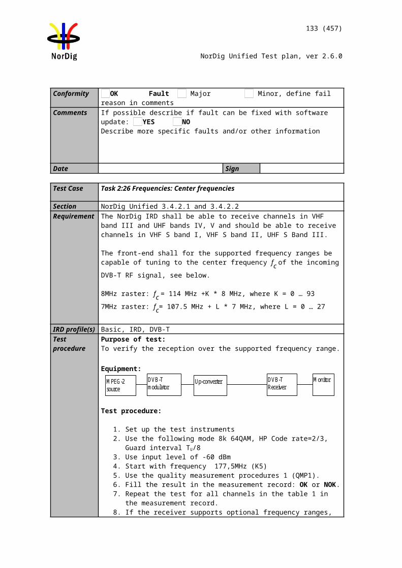
133 (457)
NorDig Unified Test plan, ver 2.6.0
For 7MHz DVB-T signal: NF[dB] = N + 105.7dBm = Cmin - C/Nmin + 105.7dBm
Expected result:
The noise figure is less than or equal to table 3.121.
Test result(s) Measurement record:
Frequency 177.5 198.5 226.5Channel id K5 K8 K12Signal bandwidth 7MHz
Mode NF [dB]8k 64QAM R2/38k 64QAM R3/4
Frequency 474.0 522.0 570.0 618.0 666.0 714.0 762.0 810.0 858.0Channel id K21 K27 K33 K39 K45 K51 K57 K63 K69
Signal bandwidth 8MHz
Mode NF [dB] 8k 64QAM
R2/38k 64QAM
R3/4Table 1. Mandatory frequencies and signal bandwidths to support.
Frequency 114.0 114.5 170.0 170.5 177.5 178.0 226.0 226.5Channel id D1 S2 D8 S10 K5 D9 D15 K12Signal bandwidth 8MHz
Mode NF [dB]8k 64QAM R2/38k 64QAM R3/4
Frequency 233.5 234.0 296.5 298.0 306.0 386.0 466.0Channel id S11 D16 S20 D24 S21 S31 S41Signal bandwidth 8MHz
Mode NF [dB]8k 64QAM R2/38k 64QAM R3/4
Table 2. Optional frequencies and signal bandwidths to support.
Conformity OK Fault Major Minor, define fail reason in commentsComments If possible describe if fault can be fixed with software update: YES NO
134 (457)
NorDig Unified Test plan, ver 2.6.0
Describe more specific faults and/or other information
Date Sign
Test Case Task 3:24 Performance: Maximum Receiver Signal Input Levels
Section NorDig Unified 3.4.10.5 and 3.4.10.6Requirement The receiver shall provide QEF reception for DVB-T signals up to a level of –35dBm.
The maximum analogue TV signal level is restricted to –20 dBm defined as the r.m.s (root mean square) value of the vision carrier at peaks of the modulated envelope.
The DVB-T signal level is valid for the modes {8K, 64-QAM, R=2/3, /Tu=1/8}, {8K, 64-QAM, R=2/3, /Tu =1/4} and {8K, 64-QAM, R=3/4, /Tu =1/4}.
IRD profile(s) Basic, IRD, DVB-TTest procedure Purpose of test:
To test that the receiver is able to handle RF signals with high value.
Equipment:
Up-converterDVB-Tmodulator
MonitorDVB-TReceiver
MPEG-2source
Powermeter
Test procedure
1. Set up the test instruments.2. Determine the attenuation of the attenuator.3. Use the following mode {8K, 64-QAM, R=2/3, /TU=1/8}.4. Set the up-converter to channel 45.5. Determine the attenuation of the attenuator and the cables.6. Turn on the receiver.7. Check that the picture is decoded correctly.8. Calculate the receiver input signal level as a function of attenuation in
attenuator. 9. Increase the receiver input signal level. until the quality measurement
procedure 1 (QMP1) is fulfilled.10. Fill in the result in the measurement record.11. Repeat the test for the modes {8K, 64-QAM, R=2/3, /TU=1/4} and {8K, 64-
QAM, R=3/4, /TU=1/4}.
Expected result:
The reception shall be QEF for input level higher than or equal to –35dBm for defined DVB-T modes.
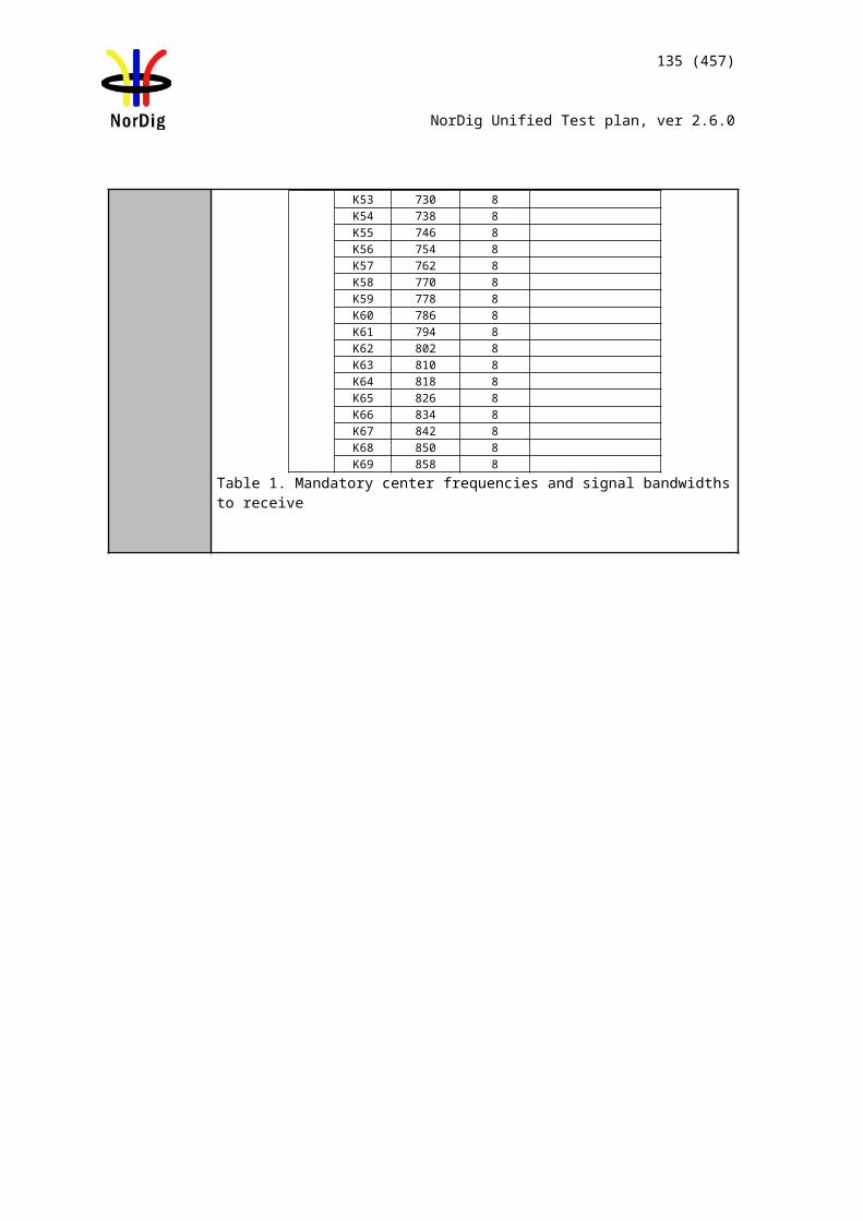
135 (457)
NorDig Unified Test plan, ver 2.6.0
Test result(s) Measurement record:
Mode Requirement dBm Result8K, 64-QAM, R=2/3, /TU=1/8 -358K, 64-QAM, R=2/3, /TU=1/4 -358K, 64-QAM, R=3/4, /TU=1/4 -35
Conformity OK Fault Major Minor, define fail reason in commentsComments If possible describe if fault can be fixed with software update: YES NO
Describe more specific faults and/or other information
Date Sign
Test Case Task 3:25 Performance: Immunity to “digital” signals in Other Channels
Section NorDig Unified 3.4.10.7.1Requirement The NorDig IRD shall, for the supported frequency ranges, permit an interfering DVB-T
signal with a minimum interference to signal level ratio (I/C) as stated in table 3.156 while maintaining QEF reception.
The requirements in this paragraph refer to the modes {8K, 64-QAM, R=2/3, /Tu =1/8} and {8K, 64-QAM, R=2/3, /Tu =1/4} and {8K, 64-QAM, R=3/4, /Tu =1/4}
IRD profile(s) Basic, IRD, DVB-TTest procedure Purpose of test:
To verify the QEF reception when there is interference from DVB-T signal on adjacent or other channels.
Equipment:
DVB-TReceiver
MonitorMPEG-2source
DVB-Tmodulator
Up-converterData MUX1
MPEG-2source
DVB-Tmodulator
Up-converterData MUX2
Channel A
Channel B
Verify that the digital TV signal on the adjacent or the other channels don’t have too high shoulders, which could cause out-of-band emissions in the reception of the wanted digital TV signal.
Test procedure:
1. Set up the test instruments2. Use the following DVB-T mode {8K, 64-QAM, R=2/3, /TU=1/8} and signal
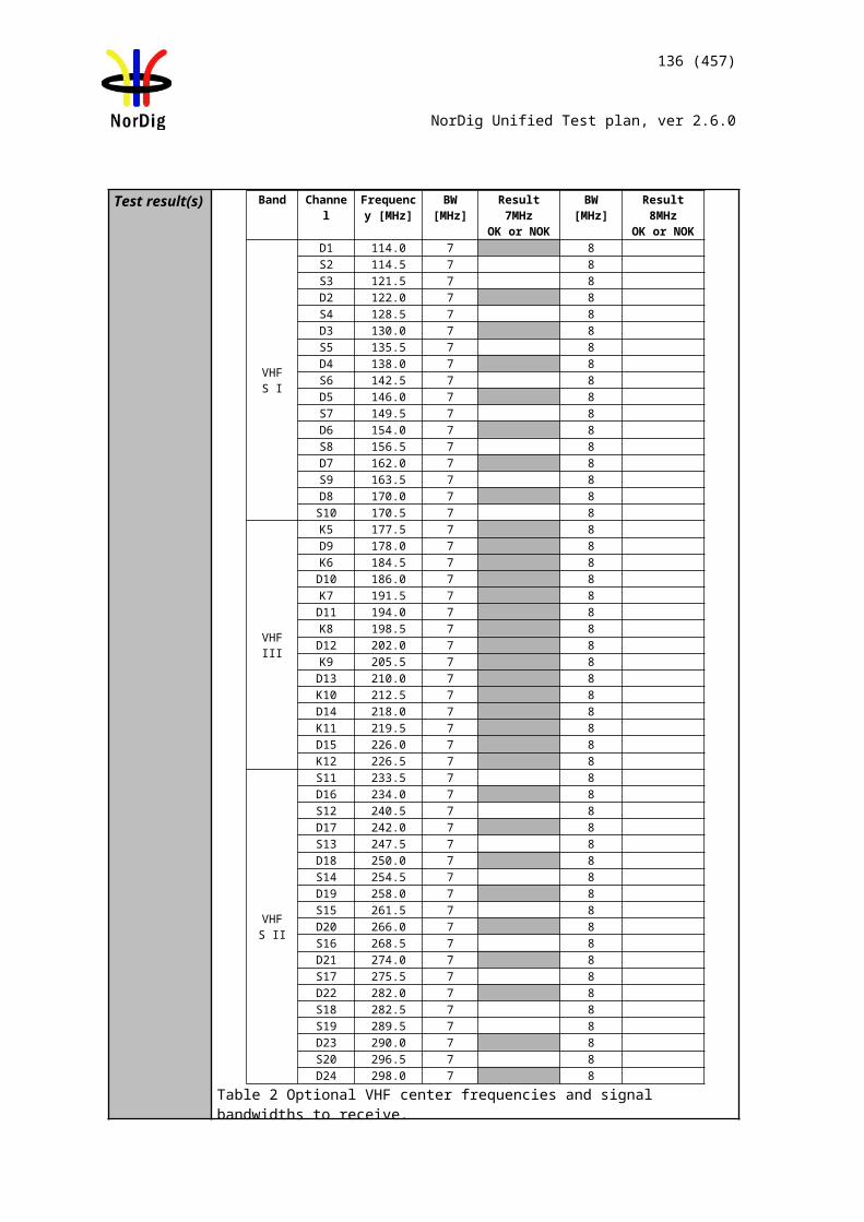
136 (457)
NorDig Unified Test plan, ver 2.6.0
bandwidth 8MHz.3. Set the channel A up-converter to 666.0MHz (K45).4. Set the channel B up-converter to 674.0MHz (K46).5. Set the receiver input level for the DVB-T signal in channel B to -30 dBm.6. Decrease the DVB-T signal level in channel A to a signal level when the
quality measurement procedure 2 (QMP2) is still fulfilled.7. Fill in the measured signal level difference between channel A and channel B
signals in dB in measurement record. 8. Repeat the test when the channel B up-converter is set to frequencies 658.0
MHz (K44), 650.0 MHz (K43), 682.0 MHz (K47).9. Repeat the test according to procedure above for the image channel1) . Set the
receiver input level for the DVB-T signal in channel B to –30dBm.10. Repeat the test for the DVB-T modes {8K, 64-QAM, R=2/3, /TU=1/4} and
{8K, 64-QAM, R=3/4, /TU=1/4} using signal bandwidth 8MHz,11. Change the signal bandwidth to 7MHz.12. Set the channel A up-converter to frequency 198.5 MHz (K8).13. Set the channel B up-converter to frequency 205.5 MHz (K9). 14. Set the receiver input level of the DVB-T signal in channel B to -30dBm. 15. Decrease the DVB-T signal level in channel A to a signal level when the
quality measurement procedure 2 is fulfilled.16. Fill in the measured signal level difference between channel A and channel B
signals in dB in measurement record. 17. Repeat the test when the channel B up-converter is set to frequencies 191.5
MHz (K7), 184.5 MHz (K6) and 212.5 MHz (K10).18. Repeat the test for the DVB-T modes {8K, 64-QAM, R=2/3, /TU=1/4} and
{8K, 64-QAM, R=3/4, /TU=1/4} using signal bandwidth 7MHz,
1) Example: if intermediate frequency IF is 36.15MHz, the image channel is calculated for channel 45 as 666MHz + 2 * 36.15MHz = 738.3MHz which is close to channel 54.
Expected result:
The protection ratios shall be fulfilled for received signal at the requested quality level for specified DVB-T modes, signal bandwidths and supported frequencies.
Test result(s) Measurement record:
7 MHz signal bandwidthInterferer center frequency [MHz] 184.5 191.5 205.5 212.5DVB-T mode / Channel id K6 K7 K9 K108K, 64-QAM, R=2/3, /TU =1/88K, 64-QAM, R=2/3, /TU =1/48K, 64-QAM, R=3/4, /TU =1/4
Table 1. Mandatory VHF Band III frequencies and signal bandwidth to support
8 MHz signal bandwidthInterferer center frequency [MHz] 650.0 658.0 674.0 682.0 738.0DVB-T mode / Channel id K43 K44 K46 K47 K548K, 64-QAM, R=2/3, /TU =1/88K, 64-QAM, R=2/3, /TU =1/48K, 64-QAM, R=3/4, /TU =1/4
Table 2. Mandatory UHF Band IV/V frequencies and signal bandwidth to support
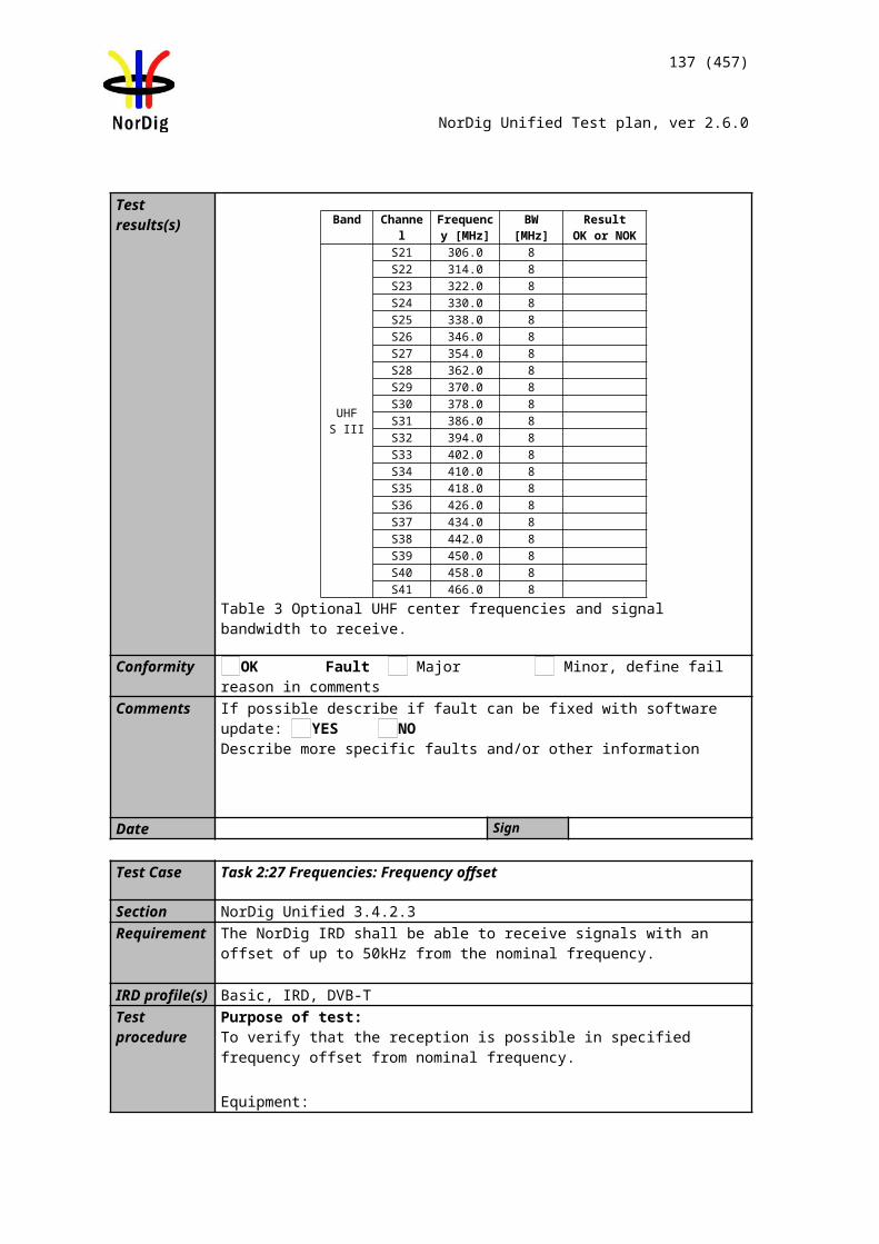
137 (457)
NorDig Unified Test plan, ver 2.6.0
7 MHz signal bandwidthCenter frequency [MHz] 128.5 135.5 149.5 156.5DVB-T mode / Channel id S4 S5 S7 S88K, 64-QAM, R=2/3, /TU =1/88K, 64-QAM, R=2/3, /TU =1/48K, 64-QAM, R=3/4, /TU =1/4
Table 3. Optional VHF S Band I frequencies and signal bandwidth to support
8 MHz signal bandwidthCenter frequency [MHz] 122.0 130.0 146.0 154.0DVB-T mode / Channel id D2 D3 D5 D68K, 64-QAM, R=2/3, /TU =1/88K, 64-QAM, R=2/3, /TU =1/48K, 64-QAM, R=3/4, /TU =1/4
Table 4. Optional VHF S Band I frequencies and signal bandwidth to support
8 MHz signal bandwidthCenter frequency [MHz] 186.0 194.0 210.0 218.0DVB-T mode / Channel id D10 D11 D13 D148K, 64-QAM, R=2/3, /TU =1/88K, 64-QAM, R=2/3, /TU =1/48K, 64-QAM, R=3/4, /TU =1/4
Table 5. Optional VHF Band III frequencies and signal bandwidth to support
7 MHz signal bandwidthCenter frequency [MHz] 247.5 254.5 268.5 275.5DVB-T mode / Channel id S13 S14 S16 S178K, 64-QAM, R=2/3, /TU =1/88K, 64-QAM, R=2/3, /TU =1/48K, 64-QAM, R=3/4, /TU =1/4
Table 6. Optional VHF S Band II frequencies and signal bandwidth to support
8 MHz signal bandwidthCenter frequency [MHz] 250.0 258.0 274.0 282.0DVB-T mode / Channel id D18 D19 D21 D228K, 64-QAM, R=2/3, /TU =1/88K, 64-QAM, R=2/3, /TU =1/48K, 64-QAM, R=3/4, /TU =1/4
Table 7. Optional VHF S Band II frequencies and signal bandwidth to support
8 MHz signal bandwidthCenter frequency [MHz] 370.0 378.0 394.0 402.0DVB-T mode / Channel id S29 S30 S32 S338K, 64-QAM, R=2/3, /TU =1/88K, 64-QAM, R=2/3, /TU =1/48K, 64-QAM, R=3/4, /TU =1/4
Table 8. Optional UHF S Band III frequencies and signal bandwidth to support
Conformity OK Fault Major Minor, define fail reason in commentsComments If possible describe if fault can be fixed with software update: YES NO
Describe more specific faults and/or other information
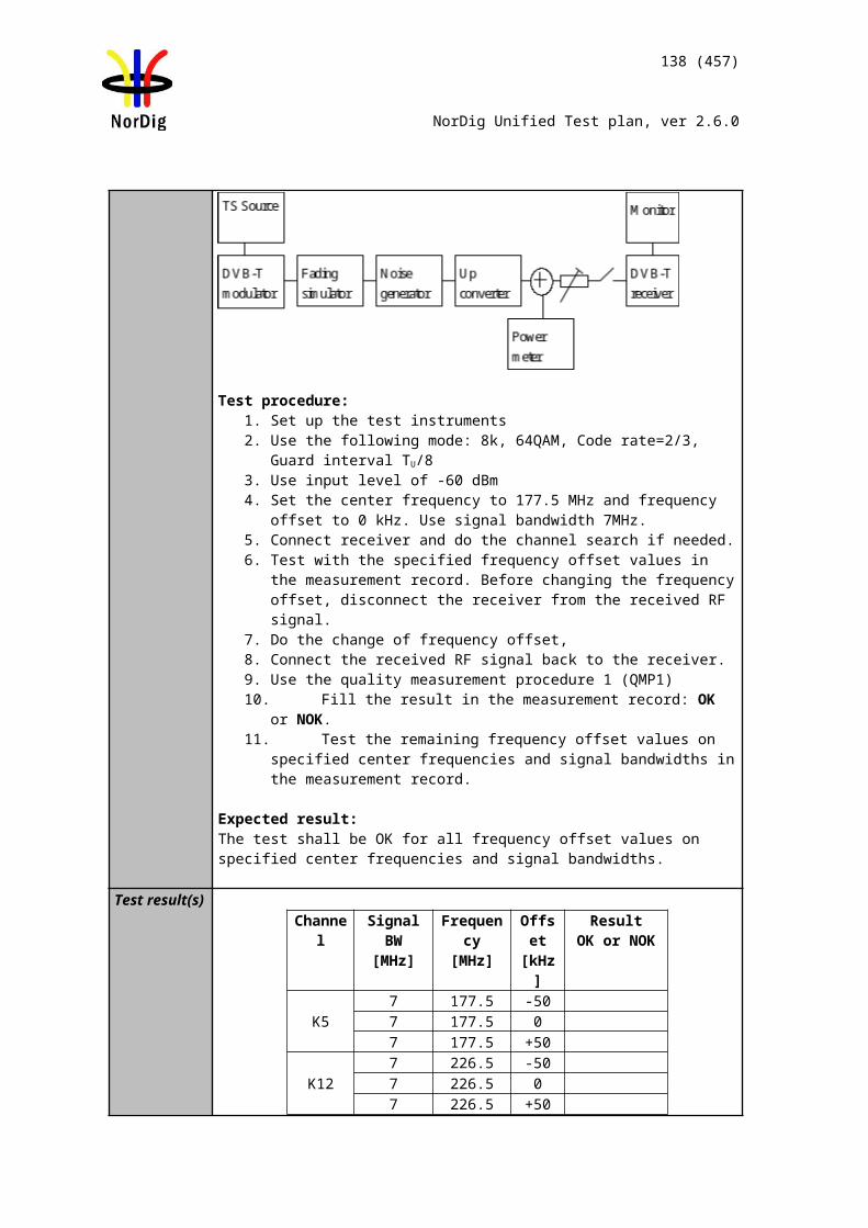
Channel B
TS source
IRD MonitorDVB-T modulator
ATT I
ATT C
LTE source
LTE modulator
Upconverter (interference)
Channel A
Spectrumanalysator
Upconverter (wanted)
138 (457)
NorDig Unified Test plan, ver 2.6.0
Date Sign
Test Case Task 3:26 Performance: Immunity to “LTE 700 MHz” signals in Other Channels
Section NorDig Unified 3.4.10.7.2Requirement The terrestrial NorDig IRD and IRD-T2 shall, for the supported frequency ranges,
permit an interfering 4G (LTE) “700MHz” signal with a minimum interference to signal level ratio (I/C) as stated in the Table 3.17xx (1) while maintaining QEF reception.
The power of the interfering LTE signal, both BS and UE, varies with a traffic load and traffic type. The signal power of the LTE signal is defined as the power during the active part of the time varying LTE signal, referred to as the licensed power level (I).
The I/C values shall (1) be fulfilled for LTE signals with traffic loads from 0% to 100 % (BS) and for traffic loads from low bit rate to high bit rate (UE). Low traffic loads can be the most demanding ones. The minimum I/C requirement shall be fulfilled for -25 dBm in case of UE signals and -15dBm in case of BS signals defined as licensed power of interfering signal, at the input of the IRD.
The requirements in this paragraph refer, for DVB-T, to following modes {FFT size, modulation, code rate, guard interval, bandwidth}; {8K, 64-QAM, R=2/3, /Tu =1/8, 8MHz} and {8K, 64-QAM, R=2/3, /Tu =1/4, 8MHz} and {8K, 64-QAM, R=3/4, /Tu =1/4, 8MHz} and and for DVB-T2 to the modes {FFT size, modulation, pilot pattern, code rate, guard interval, bandwidth}{32KE, 256-QAM R, PP4, R=2/3, /Tu =1/16, 8MHz}{32KE, 256-QAM R, PP4, R=3/5, /Tu =19/256, 8MHz}{32KN, 256-QAM R, PP4, R=2/3, /Tu =19/256, 7MHz} and
IRD Profile(s) Basic, IRD, DVB-TTest procedure Purpose of test:
To verify the QEF reception for LTE 700 MHz signal interference on adjacent or other channels.
Equipment:
Verify that the interfering LTE signal on the adjacent or the other channels don’t have too high shoulders, which could cause out-of-band emissions in the reception of the
139 (457)
NorDig Unified Test plan, ver 2.6.0
wanted digital TV signal.
From IRD point of view most demanding LTE signal might be that with low traffic load.
The LTE transmission is generated by using following LTE signal characteristics: BS 0% traffic load (LTE_BS-idle_V3_synth.wv)UE Video stream traffic (short_UE-Video-Stream_V2.wv)
Files in I/Q file format specified above are available on the ETSI website http://www.etsi.org/deliver/etsi_en/303300_303399/303340/01.01.02_60/en_303340v010102p0.zip
or if not available, they can be found on the NorDig homepage.
Test procedure:
1. Set up the test instruments2. Use the following DVB-T mode {8K, 64-QAM, R=2/3, /Tu =1/8, 8MHz }3. Set the channel A up-converter to 690.0MHz (K48).4. Set the channel B up-converter to 708.0MHz .5. Set the LTE interefer to UE Video traffic mode.6. Set the receiver input level for the LTE signal in channel B to -25 dBm.7. Decrease the wanted signal level in channel A to a signal level when the quality
measurement procedure 2 is still fulfilled.8. Fill in the measured signal level difference between channel A and channel B
signals in dB in measurement record. 9. Repeat the test when the channel B up-converter is set to frequencies 718.0
MHz, 728.0 MHz.10. Set the channel B up-converter to 763.0MHz.11. Set the LTE interefer to BS 0% traffic load mode.12. Set the receiver input level for the LTE signal in channel B to -15 dBm.13. Decrease the wanted signal level in channel A to a signal level when the quality
measurement procedure 2 is still fulfilled.14. Fill in the measured signal level difference between channel A and channel B
signals in dB in measurement record. 15. Repeat the test when the channel B up-converter is set to frequencies 773.0
MHz, 783.0 MHz.16. Repeat the test for the DVB-T mode {8K,64-QAM,R=3/4,/Tu =1/4,8MHz}.
Expected result:
The wanted DVB-T signal shall be QEF for the interference signal levels as specified.
Test result(s) Measurement record:
I/C [dB]Interferer centre frequency [MHz] 708.0 718.0 728.08K, 64-QAM, R=2/3, /Tu =1/8, 8MHz8K, 64-QAM, R=3/4, /Tu =1/4, 8MHz
Table 1. UE Video stream traffic interferer
I/C [dB]Interferer centre frequency [MHz] 763.0 773.0 783.08K, 64-QAM, R=2/3, /Tu =1/8, 8MHz8K, 64-QAM, R=3/4, /Tu =1/4, 8MHz
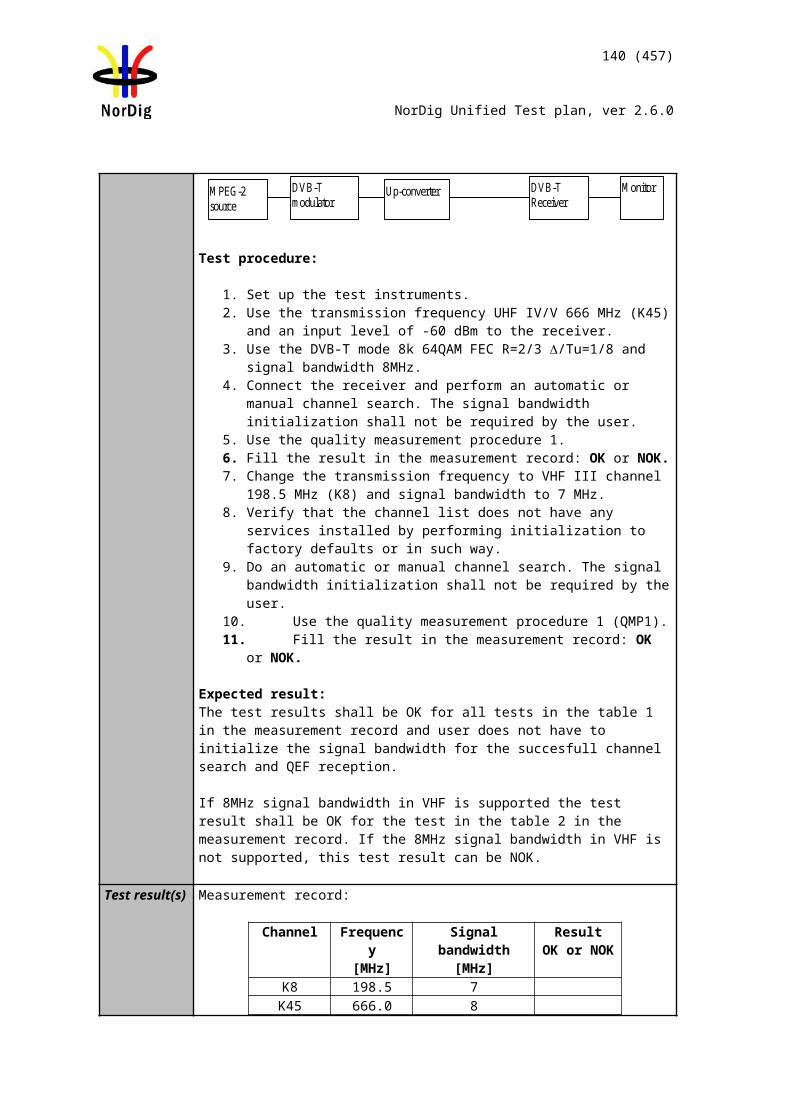
Channel B
TS source
IRD MonitorDVB-T modulator
ATT I
ATT C
LTE source
LTE modulator
Upconverter (interference)
Channel A
Spectrumanalysator
Upconverter (wanted)
140 (457)
NorDig Unified Test plan, ver 2.6.0
Table 2. BS 0% traffic load interferer
Conformity OK Fault Major Minor, define fail reason in commentsComments If possible describe if fault can be fixed with software update: YES NO
Describe more specific faults and/or other information
Date Sign
Test Case Task 3:27 Performance: Immunity to “LTE 800 MHz” signals in Other Channels
Section NorDig Unified 3.4.10.7.21Requirement The DVB-T and DVB-T2 IRD shall, for the supported frequency ranges, permit an
interfering LTE signal with a minimum interference to signal level ratio (I/C) as stated in the table 3.16 below while maintaining QEF reception.
The power of the LTE signal, both BS and UE, varies with a traffic load. The signal power of the LTE signal is defined as the power during the active part of the time varying LTE signal. The I/C values shall be fulfilled for traffic loads 0% to 100 % (BS) and for traffic loads from low bit rate to high bit rate (UE). Low traffic loads can be the most demanding ones. The minimum I/C requirement shall be fulfilled for -15dBm defined as licensed power of interfering signal, at the input of the IRD.
The requirements in this paragraph refer, for DVB-T, to the modes {8K, 64-QAM, R=2/3, /Tu =1/8, 8MHz} and {8K, 64-QAM, R=2/3, /Tu =1/4, 8MHz} and {8K, 64-QAM, R=3/4, /Tu =1/4, 8MHz} and for DVB-T2 to the modes {32KE, 256-QAM R, PP4, R=2/3, /Tu =1/16, 8MHz}{32KE, 256-QAM R, PP4, R=3/5, /Tu =19/256, 8MHz}{32KN, 256-QAM R, PP4, R=2/3, /Tu =19/256, 7MHz} and
IRD Profile(s) Basic, IRD, DVB-TTest procedure Purpose of test:
To verify the QEF reception for LTE signal interference on adjacent or other channels.
Equipment:
Verify that the interfering LTE signal on the adjacent or the other channels don’t have
141 (457)
NorDig Unified Test plan, ver 2.6.0
too high shoulders, which could cause out-of-band emissions in the reception of the wanted digital TV signal.
From IRD point of view most demanding LTE signal might be that with low traffic load.
The LTE transmission is generated by using following LTE signal characteristics: LTE_BS-idle_V2.wv (BS 0% traffic load)LTE_UE_1Mbs_V2.wv (UE 1 MBit/s traffic load)Files in I/Q file format are available on NorDig homepage.
Use Mode A (Single PLP) and Lf parameter settings defined by Teracom for the modes.
Test procedure:
1. Set up the test instruments2. Use the following DVB-T mode {8K, 64-QAM, R=2/3, /Tu =1/8, 8MHz}3. Set the channel A up-converter to 786.0MHz (K60).4. Set the channel B up-converter to 796.0MHz .5. Set the LTE interefer to BS 0% traffic load mode.6. Set the receiver input level for the LTE signal in channel B to -15 dBm.7. Decrease the wanted signal level in channel A to a signal level when the quality
measurement procedure 2 is still fulfilled.8. Fill in the measured signal level difference between channel A and channel B
signals in dB in measurement record. 9. Repeat the test when the channel B up-converter is set to frequencies 806.0
MHz, 816.0 MHz.10. Set the channel B up-converter to 837.0MHz.11. Set the LTE interefer to UE 1 MBit/s traffic load mode. 12. Set the receiver input level for the LTE signal in channel B to -15 dBm.13. Decrease the wanted signal level in channel A to a signal level when the quality
measurement procedure 2 is still fulfilled.14. Fill in the measured signal level difference between channel A and channel B
signals in dB in measurement record. 15. Repeat the test when the channel B up-converter is set to frequencies 847.0
MHz, 857.0 MHz.16. Repeat the test for the DVB-T mode {8K, 64-QAM, R=2/3, /Tu =1/4,
8MHz}.17. Repeat the test for the DVB-T mode {8K, 64-QAM, R=3/4, /Tu =1/4,
8MHz}.
Expected result:
The wanted DVB-T signal shall be QEF for the interference signal levels as specified.
Test result(s) Measurement record:
I/C [dB]Interferer centre frequency [MHz] 796.0 806.0 816.08K, 64-QAM, R=2/3, /Tu =1/8, 8MHz8K, 64-QAM, R=2/3, /Tu =1/4, 8MHz8K, 64-QAM, R=3/4, /Tu =1/4, 8MHz
Table 1. BS 0% interferer I/C [dB]
Interferer centre frequency [MHz] 837.0 847.0 857.08K, 64-QAM, R=2/3, /Tu =1/8, 8MHz
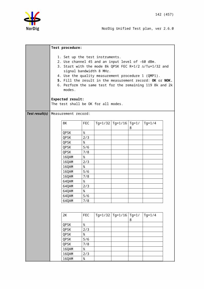
142 (457)
NorDig Unified Test plan, ver 2.6.0
8K, 64-QAM, R=2/3, /Tu =1/4, 8MHz8K, 64-QAM, R=3/4, /Tu =1/4, 8MHz
Table 2. UE 1 Mbit/s interferer
Conformity OK Fault Major Minor, define fail reason in commentsComments If possible describe if fault can be fixed with software update: YES NO
Describe more specific faults and/or other information
Date Sign
Test Case Task 3:28 Performance: Performance in Time-Varying Channels
Section NorDig Unified 3.4.10.9Requirement The NorDig IRD shall be able to operate with all signal time variations that naturally
exist in connection with fixed roof-top reception (e.g. mast sway, antenna sway) and in-house portable reception (e.g. people walking around the receiving antenna). None of the above mentioned performance parameters should be significantly negatively affected when such channel time variations exist.
The increase in required C/N for QEF reception shall be less than 3 dB for a 0 dB echo with frequency separation equal to 20 Hz and a delay of 20 µs, corresponding to a Doppler shift of +/- 10 Hz (after AFC), compared to a 0 dB echo with frequency separation equal to 1 Hz and a delay of 20 µs, corresponding to a Doppler shift of +/- 0.5 Hz (after AFC). The requirements in this paragraph refer to the modes {8K, 64-QAM, R=2/3, /Tu =1/8} and {8K, 64-QAM, R=2/3, /Tu =1/4}.
The increase in required C/N for QEF reception shall be less than 3 dB for a 0 dB echo with frequency separation equal to 10 Hz and a delay of 20 µs, corresponding to a Doppler shift of +/- 5 Hz (after AFC), compared to a 0 dB echo with frequency separation equal to 1 Hz and a delay of 20 µs, corresponding to a Doppler shift of +/- 0.5 Hz (after AFC). The requirement in this paragraph refer to the mode {8K, 64-QAM, R=3/4, /Tu =1/4}.
IRD profile(s) Basic, IRD, DVB-TTest procedure Purpose of test:
To verify the reception on a channel where time variations exists.
Equipment:
The 0 degree channel center shall be used in fading simulator . This is valid for 0Hz
143 (457)
NorDig Unified Test plan, ver 2.6.0
doppler shift.
Test procedure:
1. Set up the test instruments. 2. Use the following mode: {8K, 64-QAM, R=2/3, /TU=1/8}. 3. Use channel 45.4. Configure path 1 to type of static, attenuation 0dB, delay 0µs. 5. Configure path 2 to type of pure Doppler, attenuation 0dB, delay 20µs and
frequency separation to 0Hz. 6. Set the receiver input level to -50 dBm. 7. Increase the C/N from low value to higher value until the quality measurement
procedure 2 (QMP2) is fulfilled. 8. Fill in the measured value in dB in the measurement record. 9. Repeat the test for the rest of the frequency separation values in the
measurement record. Be careful of value which is configured in fading simulator. It can be speed, Doppler or frequency separation.
10. Fill the C/N result in the measurement record.11. Repeat the test for the DVB-T modes {8K, 64-QAM, R=2/3, /TU =1/4} and
{8K, 64-QAM, R=3/4, /TU =1/4}.
Expected result:For the DVB-T modes {8K, 64-QAM, R=2/3, /TU =1/8} and {8k, 64QAM, R=2/3, /TU =1/4} the increase in the required C/N shall be less than 3dB for 0dB 20µs echo from frequency separation 1Hz to 20Hz. For the mode {8K, 64-QAM, R=3/4, /TU =1/4} the increase in the required C/N shall be less than 3dB for 0dB 20µs echo from frequency separation 1Hz to 10Hz.
Test result(s) Measurement record:
Mode 0dB echo delay [µs]
Frequency separation
[Hz]
C/N [dB]
{8K, 64-QAM, R=2/3, /TU =1/8} 20µs 0Hz{8K, 64-QAM, R=2/3, /TU =1/8} 20µs 1Hz{8K, 64-QAM, R=2/3, /TU =1/8} 20µs 5Hz{8K, 64-QAM, R=2/3, /TU =1/8} 20µs 10Hz{8K, 64-QAM, R=2/3, /TU =1/8} 20µs 15Hz{8K, 64-QAM, R=2/3, /TU =1/8} 20µs 20Hz
{8K, 64-QAM, R=2/3, /TU =1/4} 20µs 0Hz{8K, 64-QAM, R=2/3, /TU =1/4} 20µs 1Hz{8K, 64-QAM, R=2/3, /TU =1/4} 20µs 5Hz{8K, 64-QAM, R=2/3, /TU =1/4} 20µs 10Hz{8K, 64-QAM, R=2/3, /TU =1/4} 20µs 15Hz{8K, 64-QAM, R=2/3, /TU =1/4} 20µs 20Hz
{8K, 64-QAM, R=3/4, /TU =1/4} 20µs 0Hz{8K, 64-QAM, R=3/4, /TU =1/4} 20µs 1Hz{8K, 64-QAM, R=3/4, /TU =1/4} 20µs 5Hz{8K, 64-QAM, R=3/4, /TU =1/4} 20µs 10Hz
Conformity OK Fault Major Minor, define fail reason in commentsComments If possible describe if fault can be fixed with software update: YES NO
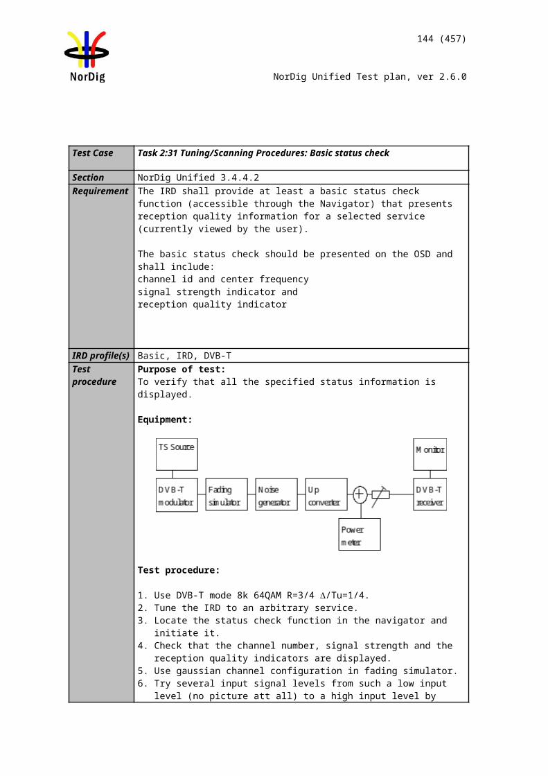
144 (457)
NorDig Unified Test plan, ver 2.6.0
Describe more specific faults and/or other information
Date Sign
Test Case Task 3:29 Performance: Synchronisation for varying echo power levels in SFN
Section NorDig Unified 3.4.10.10Requirement For the modes {8K, 64-QAM, R=2/3, ∆/Tu=1/8}, {8K, 64-QAM, R=2/3, ∆/Tu =1/4}
and {8K, 64-QAM, R=3/4, ∆/Tu =1/4}, the required C/N value for subjective error free reception shall be obtained when the channel contains two paths with relative delay from 1.95 µs up to 0.95 times guard interval length and the relative power levels of the two paths are dynamically varying including 0dB echo level crossing. The C/N value is defined at 0 dB level crossing.
IRD profile(s) Basic, IRD, DVB-TTest procedure Purpose of test:
To verify the SFN synchronisation when the amplitude of the echo compared to the amplitude of the direct signal varies in a function of time.
Equipment:
The 0 degree channel center shall be used in fading simulator (see2.3.5).
Test procedure for variations of the echo attenuation in a function of time:
Check the different SFN synchronisation issues from 2.3.4 Receiver operability in SFN.
1. Set up the test instruments.2. Use the following mode {8K, 64-QAM, R=3/4, /TU=1/4}.3. Open the switch.4. Configure the first path signal (direct) with following parameters: 0dB
attenuation and 0µs delay. 5. Configure the second path signal (1st echo) with following parameters: 0dB
attenuation and first delay value from the measurement record. . 6. Set the receiver input level to -50 dBm.7. Configure the third path signal (2nd echo) with following parameters: 1dB
attenuation and delay same as for the second path and 0.1Hz frequency separation.
8. Close the switch.9. Increase the C/N from low value to higher value until the quality measurement
145 (457)
NorDig Unified Test plan, ver 2.6.0
procedure 2 (QMP2) is fulfilled. 10. Fill in the measured required C/N value in dB in the measurement record.11. Repeat the test for the rest of the echo delay values in the measurement record
following the procedure above. Between change of the echo delay, RF input signal to the receiver shall be disconnect.
12. Repeat the test for the DVB-T modes {8K, 64-QAM, R=2/3, /TU =1/8} and {8K, 64-QAM, R=2/3, /TU =1/4}.
Expected result:The IRD shall maintain the SFN synchronisation when the amplitude of the echo signal varies in a function of time. The required C/N shall not exceed the specified value in table 3.18.
Test result(s) Measurement record:
F = 666.0 MHz (K45) and signal bandwidth 8 MHz.Mode 10µs 56µs 105µs 112.1 µs 130 µs 170µs 212µs8k 64QAM R2/3 G1/88k 64QAM R3/4 G1/48k 64QAM R2/3 G1/4
Conformity OK Fault Major Minor, define fail reason in commentsComments If possible describe if fault can be fixed with software update: YES NO
Describe more specific faults and/or other information
Date Sign
Test Case Task 3:30 Performance: C/(N+I) Performance in SFN for more than one echo
Section NorDig Unified 3.4.10.11Requirement If there exists one or more FFT window positions for the time synchronisation that will
give an aggregate available C/(N+I) larger than or equal to the required EPT (Effective Protection Target), the NorDig IRD shall be able to find one of these positions, independently of echo profile. The NorDig IRD shall also be able to correctly equalise the signal for echoes up to 7TU/24 (260 µs) (Interval of correct equalisation), independently of the echo profile.
1) EPT = Effective Protection Target
IRD profile(s) Basic, IRD, DVB-TTest procedure Purpose of test:
To verify the SFN synchronization of the receiver when two echo signals are present.
Equipment:
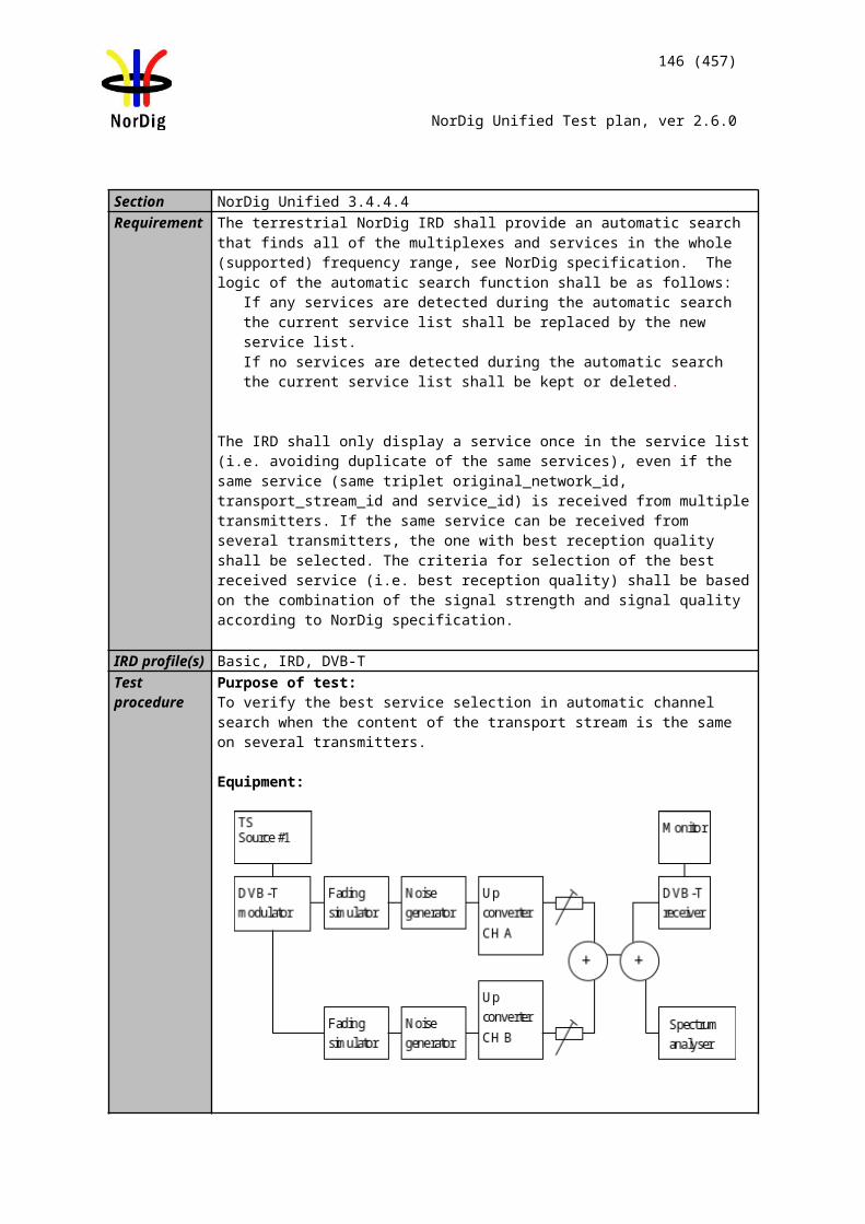
146 (457)
NorDig Unified Test plan, ver 2.6.0
The 0 degree at channel center shall be used in fading simulator (see2.3.5).
Test procedure:
Check the different SFN synchronisation issues from 2.3.4 Receiver operability in SFN.
1. Set up the test instruments.2. Use the following DVB-T mode {8K, 64-QAM, R=3/4, /TU=1/4} and signal
bandwidth 8MHz.3. Open the switch.4. Conifigure one path of the channel simulator to have a 0dB attenuation, 0µs
delay and 0 degree phase.5. Configure the second path of the channel simulator to have relative delay
difference –100.1µs and attenuation 21dB (pre echo) and 0 degree phase.6. Configure the third path of the channel simulator to have relative delay
difference +100.0µs and attenuation 15 dB (post echo) and 0 degree phase. 7. Set the receiver input level to -50 dBm.8. Close the switch.9. Increase the required C/N value from low value to higher value until the quality
measurement procedure 2 (QMP2) is fulfilled.10. Fill in the required C/N value in dB in the measurement record. 11. Measure the rest of the required C/N values starting at the bottom of the table
and upward. 12. Fill in the results in the measurement record. During the change of the delay
and the attenuation, the input RF signal to receiver shall be disconnected. 13. Repeat the test for the DVB-T mode {8K, 64-QAM, R=2/3, /TU =1/8}.14. Repeat the test for the DVB-T mode {8K, 64-QAM, R=2/3, /TU =1/4}.
Expected result:The IRD shall synchronize in all combinations defined in measurement record and the required C/N value shall not exceed the required C/N defined for profile 2: 0dB echo in table 3.109.
Test result(s) Measurement record:8k 64QAM R=3/4 /TU=1/4, 8MHz
Main path Pre echo Post echo C/N [dB]
Att [dB] Delay [us] Att [dB] Delay [us] Att [dB] Delay [us]
0 0 0 -100.1 0 100
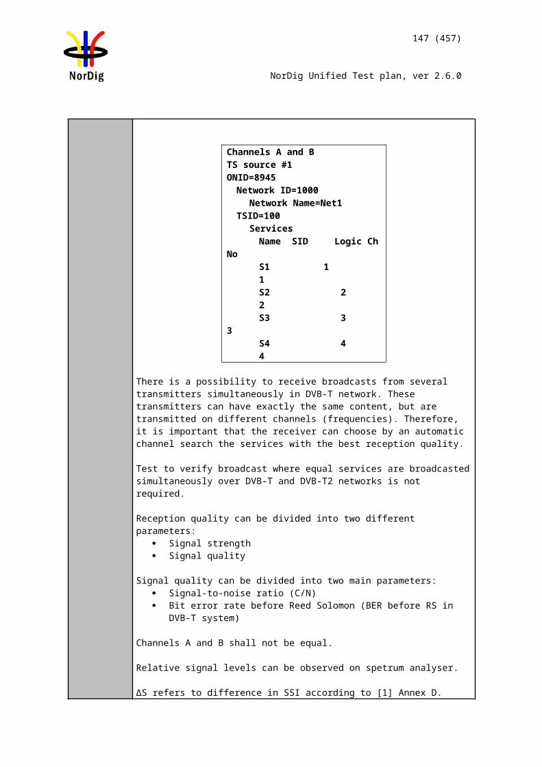
147 (457)
NorDig Unified Test plan, ver 2.6.0
0 0 3 -100.1 3 100
0 0 6 -100.1 6 100
0 0 9 -100.1 9 100
0 0 12 -100.1 12 100
0 0 15 -100.1 15 100
0 0 18 -100.1 18 100
0 0 21 -100.1 21 100
0 0 15 -100.1 0 100
0 0 15 -100.1 3 100
0 0 15 -100.1 6 100
0 0 15 -100.1 9 100
0 0 15 -100.1 12 100
0 0 15 -100.1 18 100
0 0 15 -100.1 21 100
0 0 0 -100.1 15 100
0 0 3 -100.1 15 100
0 0 6 -100.1 15 100
0 0 9 -100.1 15 100
0 0 12 -100.1 15 100
0 0 18 -100.1 15 100
0 0 21 -100.1 15 100
8k 64QAM R=2/3 /TU=1/8, 8MHz
Main path Pre echo Post echo C/N [dB]
Att [dB] Delay [us] Att [dB] Delay [us] Att [dB] Delay [us]
0 0 0 -50.1 0 50
0 0 3 -50.1 3 50
0 0 6 -50.1 6 50
0 0 9 -50.1 9 50
0 0 12 -50.1 12 50
0 0 15 -50.1 15 50
0 0 18 -50.1 18 50
0 0 21 -50.1 21 50
0 0 15 -50.1 0 50
0 0 15 -50.1 3 50
0 0 15 -50.1 6 50
0 0 15 -50.1 9 50
0 0 15 -50.1 12 50
0 0 15 -50.1 18 50
0 0 15 -50.1 21 50
0 0 0 -50.1 15 50
0 0 3 -50.1 15 50
0 0 6 -50.1 15 50
0 0 9 -50.1 15 50
0 0 12 -50.1 15 50
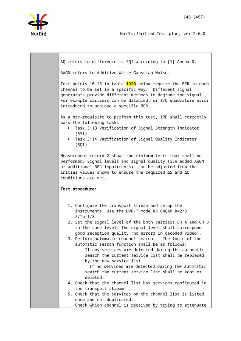
148 (457)
NorDig Unified Test plan, ver 2.6.0
0 0 15 -50.1 15 50
0 0 18 -50.1 15 50
0 0 21 -50.1 15 50
8k 64QAM R=2/3 /TU=1/4, 8MHz
Main path Pre echo Post echo C/N [dB]
Att [dB] Delay [us] Att [dB] Delay [us] Att [dB] Delay [us]
0 0 0 -100.1 0 100
0 0 3 -100.1 3 100
0 0 6 -100.1 6 100
0 0 9 -100.1 9 100
0 0 12 -100.1 12 100
0 0 15 -100.1 15 100
0 0 18 -100.1 18 100
0 0 21 -100.1 21 100
0 0 15 -100.1 0 100
0 0 15 -100.1 3 100
0 0 15 -100.1 6 100
0 0 15 -100.1 9 100
0 0 15 -100.1 12 100
0 0 15 -100.1 18 100
0 0 15 -100.1 21 100
0 0 0 -100.1 15 100
0 0 3 -100.1 15 100
0 0 6 -100.1 15 100
0 0 9 -100.1 15 100
0 0 12 -100.1 15 100
0 0 18 -100.1 15 100
0 0 21 -100.1 15 100Conformity OK Fault Major Minor, define fail reason in commentsComments If possible describe if fault can be fixed with software update: YES NO
Describe more specific faults and/or other information
Date Sign
Test Case Task 3:31 Performance: C/(N+I) Performance in SFN inside the guard interval
Section NorDig Unified 3.4.10.11Requirement For the modes {8K, 64-QAM, R=2/3, /Tu=1/8}, {8K, 64-QAM, R=2/3, /Tu =1/4} and
{8K, 64-QAM, R=3/4, /Tu =1/4}, the required C/N value for profile 2 (specified in Table 3.10) for QEF reception shall be obtained when the channel contains two static paths with relative delay from 1.95 µs up to 0.95 times guard interval length, independently of the relative amplitudes and phases of the twopaths.
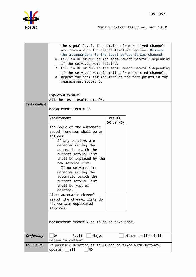
149 (457)
NorDig Unified Test plan, ver 2.6.0
For specific echo attenuation, the required C/N shall not be more than 1 dB higher compared to the median value when calculated for the required C/N values over the echo delays from 1.95 μs up to 0.95 times guard interval length.
IRD profile(s) Basic, IRD, DVB-TTest procedure Purpose of test:
To verify the required C/N for echoes in SFN inside the guard interval. Equipment:
The 0 degree channel center shall be used in fading simulator (see 2.3.5).
Test procedure for required C/N in SFN for echoes inside guard interval:
Check the different SFN synchronisation issues from 2.3.4 Receiver operability in SFN.
1. Set up the test instruments.2. Use the following DVB-T mode {8K, 64-QAM, R=3/4, /TU=1/4} and signal
bandwidth 8MHz.3. Set the up-converter to center frequency 666MHz (K45).4. Open the switch.5. Set the receiver input level to -50 dBm for the wanted signal.6. Set the channel simulator relative delay difference to 1.95 us for the echo
signal.7. Set the channel simulator relative attenuation level to 0 dB for the echo signal.8. Set C/N to such a ratio that receiver is unlocked state and reception is not
possible.9. Close the switch.10. Increase the C/N value until the quality measurement procedure 2 (QMP2) is
fulfilled.11. Fill in the required C/N value in dB in the measurement record. 12. Measure the rest of the required C/N values for the negative and positive 0dB
echoes. Fill in the results in the measurement record. During the change of the delay the input RF signal shall be disconnected.
13. Test the rest of the combinations (not marked grey) of the relative delays and attenuation levels. The delay of the echo is maintained constant when the change of the attenuation from 21dB to 1dB is done. Find the required C/N value when the reception still fulfils the quality measurement procedure 2 (QMP2). During the change of the delay and attenuation level the input RF signal shall be disconnected.

150 (457)
NorDig Unified Test plan, ver 2.6.0
14. Continue test from step 4 by repeating the test for the DVB-T mode {8K, 64-QAM, R=2/3, /TU =1/8} and signal bandwidth 8MHz.
15. Continue test from step 4 by repeating the test for the DVB-T mode {8K, 64-QAM, R=2/3, /TU =1/4} and signal bandwidth 8MHz.
16. Set the up-converter to center frequency 198.5MHz (K8).17. Continue test from the step 4 by repeating the test for the DVB-T mode {8K,
64-QAM, R=3/4, /TU=1/4} and signal bandwidth 7MHz.18. Continue test from the step 4 by repeating the test for the DVB-T mode {8K,
64-QAM, R=2/3, /TU =1/8} and signal bandwidth 7MHz.19. Continue test from the step 4 by repeating the test for the DVB-T mode {8K,
64-QAM, R=2/3, /TU =1/4} and signal bandwidth 7MHz.
Expected result:The IRD shall synchronize in all echo attenuation and delay combinations except the longest values according to below:
8K, 64-QAM, R=2/3, /TU =1/8, 8MHZ : -110µs and 110µs 8K, 64-QAM, R=3/4, /TU=1/4, 8MHZ : -220µs and 220µs8K, 64-QAM, R=2/3, /TU =1/4, 8MHZ : -220µs and 220µs8K, 64-QAM, R=2/3, /TU =1/8, 7MHZ : -126µs and +126µs8K, 64-QAM, R=3/4, /TU=1/4, 7MHZ : -252µs and 252µs8K, 64-QAM, R=2/3, /TU =1/4, 7MHZ : -252µs and 252µs
The required C/N value for 0dB echo shall not be higher than defined in table 3.109.The required C/N for a specific echo amplitude shall not be more than 1 dB higher compared to the median value when calculated for the required C/N values over the echo lengths from 1.95µs up to 0.95 times guard interval length.
Test result(s) Measurement record:
8k 64QAM R=3/4 /TU=1/4, 8MHzdB/us
1.95 10 28 56 90 112.1 130 150 170 190 212 220
0123456789101112131415161718192021
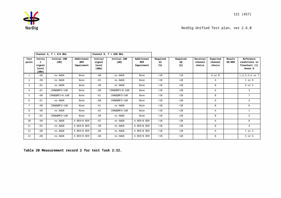
151 (457)
NorDig Unified Test plan, ver 2.6.0
dB/us
-1.95 -10 -28 -56 -90 -112.1 -130 -150 -170 -190 -212 -220
0123456789101112131415161718192021
8k 64QAM R=2/3 /TU=1/8, 8MHzdB/us
1.95 10 20 28 56 70 80 90 105 110
0123456789101112131415161718192021
dB/us
-1.95 -10 -20 -28 -56 -70 -80 -90 -105 -110
0123456789
152 (457)
NorDig Unified Test plan, ver 2.6.0
101112131415161718192021
8k 64QAM R=2/3 /TU=1/4, 8MHzdB/us
1.95 10 28 56 90 112.1 130 150 170 190 212 220
0123456789101112131415161718192021
dB/us
-1.95 -10 -28 -56 -90 -112.1 -130 -150 -170 -190 -212 -220
0123456789101112131415
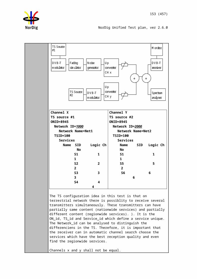
153 (457)
NorDig Unified Test plan, ver 2.6.0
161718192021
8k 64QAM R=3/4 /TU=1/4, 7MHzdB/us
1.95 10 28 64 90 128.1 150 170 190 243 252
0123456789101112131415161718192021
dB/us
-1.95 -10 -28 -64 -90 -128.1 -150 -170 -190 -243 -252
0123456789101112131415161718192021
8k 64QAM R=2/3 /TU=1/8, 7MHzdB/us
1.95 10 28 64 70 80 90 121 126
01
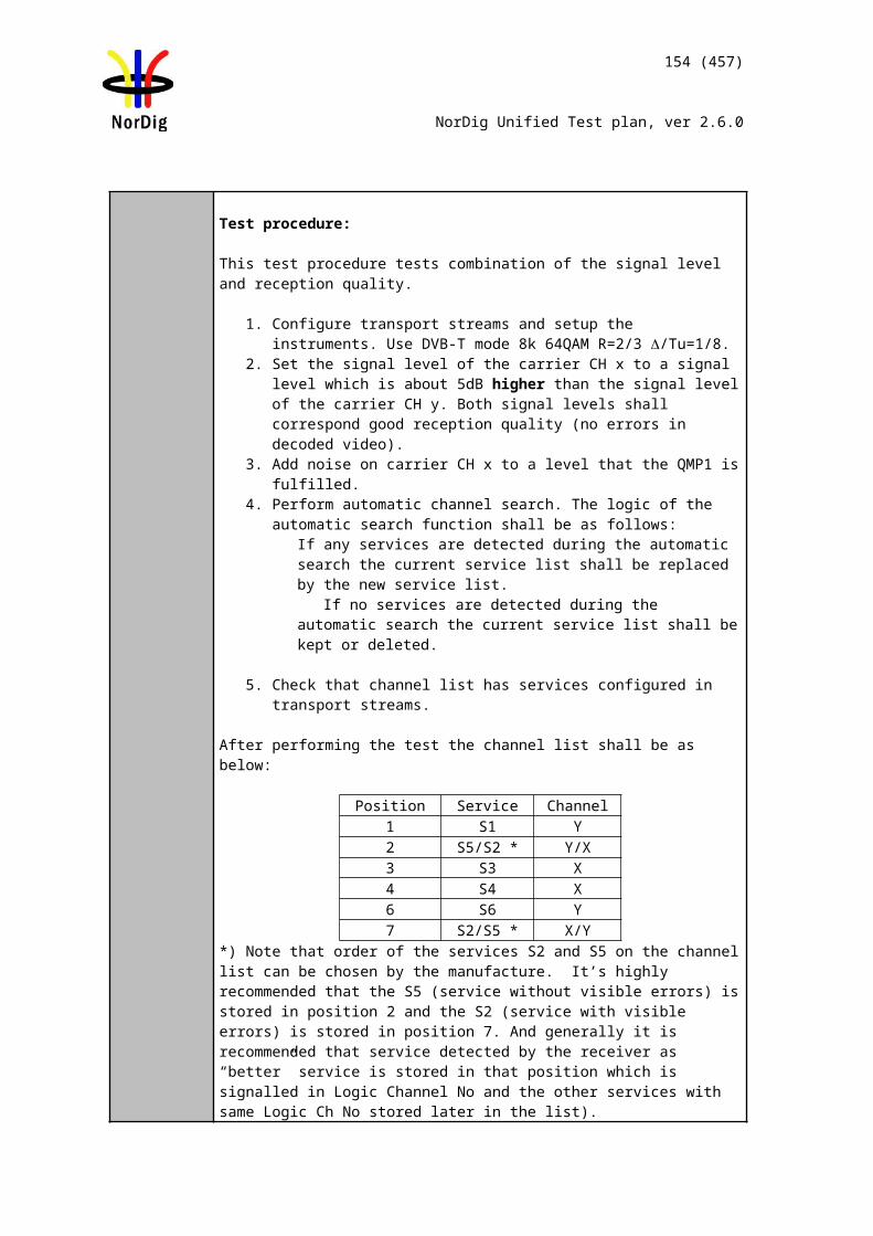
154 (457)
NorDig Unified Test plan, ver 2.6.0
23456789101112131415161718192021
dB/us
-1.95 -10 -28 -64 -70 -80 -90 -121 -126
0123456789101112131415161718192021
8k 64QAM R=2/3 /TU=1/4, 7MHzdB/us
1.95 10 28 64 90 128.1 150 170 190 243 252
012345678910111213
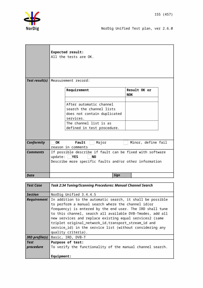
155 (457)
NorDig Unified Test plan, ver 2.6.0
1415161718192021
dB/us
-1.95 -10 -28 -64 -90 -128.1 -150 -170 -190 -243 -252
0123456789101112131415161718192021
Conformity OK Fault Major Minor, define fail reason in commentsComments If possible describe if fault can be fixed with software update: YES NO
Describe more specific faults and/or other information
Date Sign
Test Case Task 3:32 Performance: C/(N+I) Performance in SFN outside the guard interval
Section NorDig Unified 3.4.10.11Requirement For echoes outside the guard interval, for 8MHz DVB-T signal, QEF reception shall be
possible with echo levels up the values defined in Table 3.202
0For echoes outside the guard interval, for 7MHz DVB-T signal, QEF reception shall be possible with echo levels up the values defined in Table 3.213.
IRD profile(s) Basic, IRD, DVB-TTest procedure Purpose of test:
To verify the SFN synchronisation in SFN for echoes outside guard interval.
Equipment:
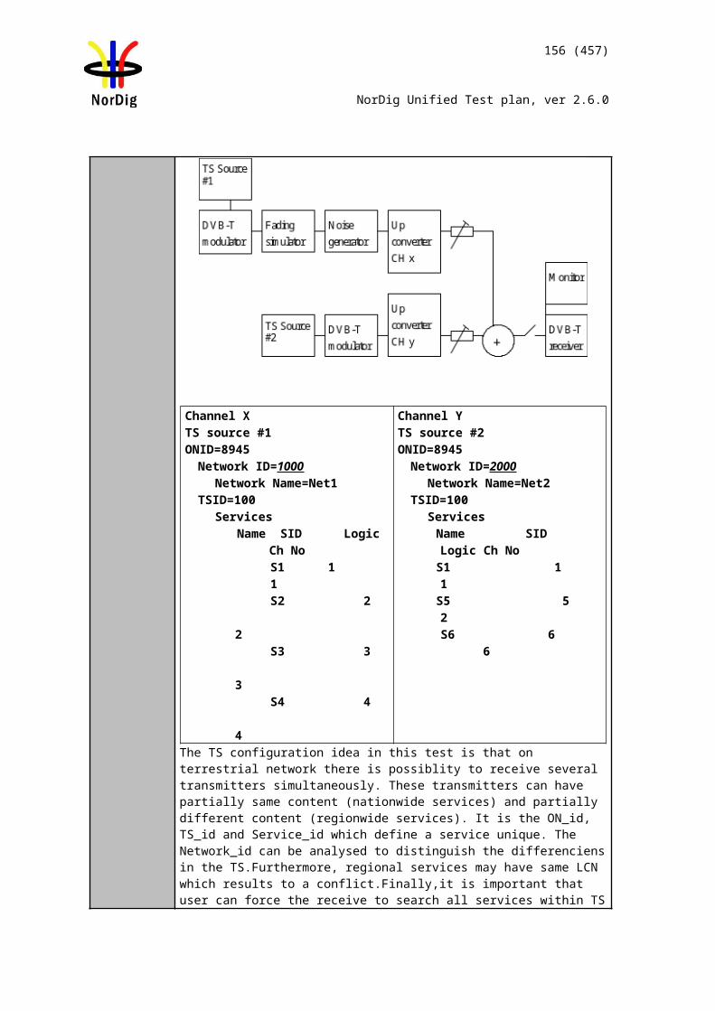
156 (457)
NorDig Unified Test plan, ver 2.6.0
Test procedure for evaluation of synchronization for echoes outside the guard interval:
Check the different SFN synchronisation issues from 2.3.4 Receiver operability in SFN. 1. Set up the test instruments.2. Use the following mode {8K, 64-QAM, R=3/4, /TU=1/4} and signal
bandwidth 8MHz.3. Open the switch.4. Set the receiver input level to -50 dBm for the wanted signal.5. Set the channel simulator relative delay difference to 230us for the echo signal.6. Close the switch.7. Increase the echo attenuation from low value to higher value until quality
measurement procedure 2 (QMP2)is fulfilled.8. Fill in echo attenuation result in dB in the measurement record. 9. Repeat the test the rest of the combinations of the relative delays and
attenuation levels defined in measurement record.. Open the switch before changing the delay and attenuation level.
10. Repeat the test for the DVB-T modes {8K, 64-QAM, R=2/3, /TU =1/8} and {8K, 64-QAM, R=2/3, /TU =1/4}.
11. Set the up-converter to center frequency 198.5MHz (K8).12. Follow the test procedure and repeat the test for the 7 MHz signal banwidth and
DVB-T modes defined in the measurement record according to procedure above.
Expected result:All the echo attenuation values shall be equal or lower compared to NorDig Unified values in tables 3.20 and 3.21.
Test result(s) Measurement record:
7 MHz signal bandwidthDVB-T mode Echo delay [µs]
-298 -266 -256 -215 -165 -135 -1288k 64QAM R2/3 G1/88k 64QAM R2/3 G1/48k 64QAM R3/4 G1/4
Echo delay [µs]298 266 256 215 165 135 128
8k 64QAM R2/3 G1/8
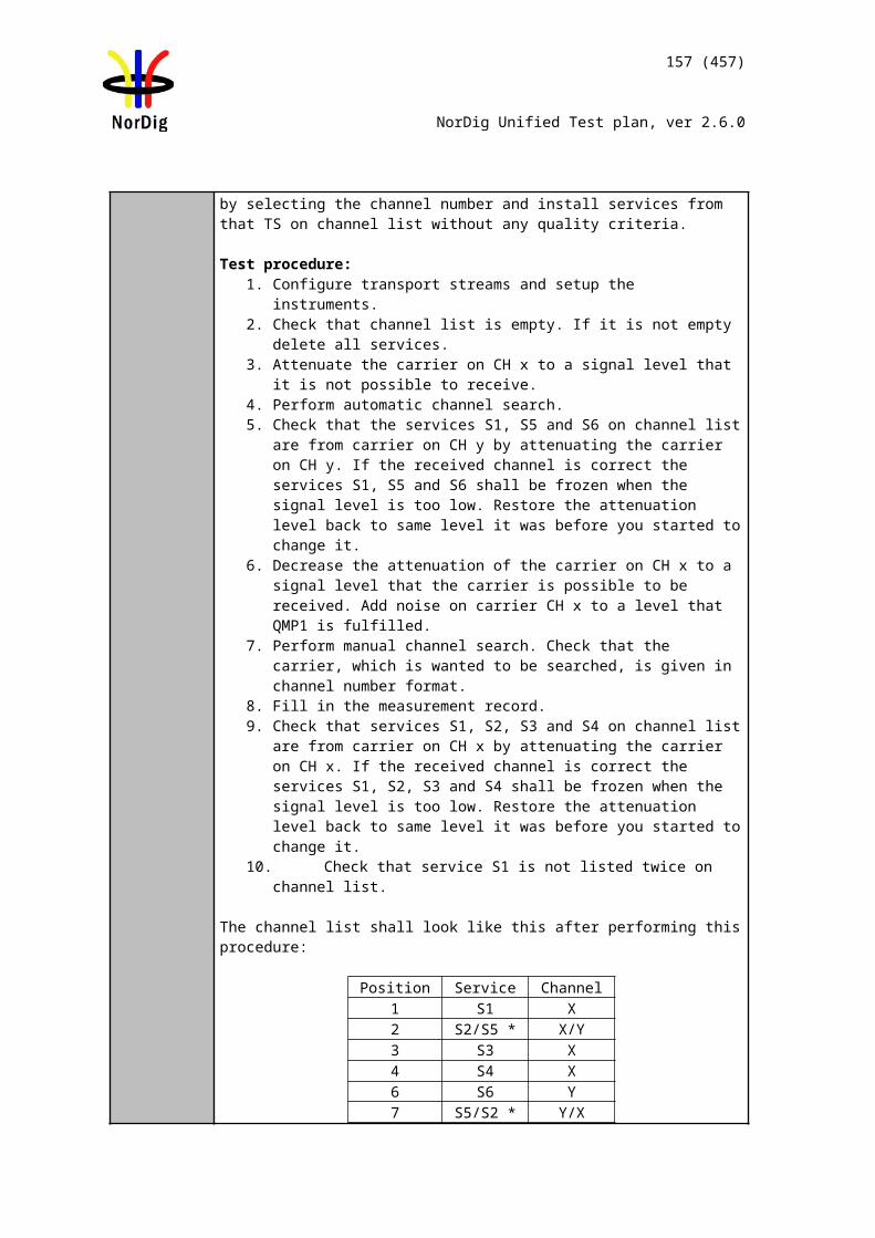
157 (457)
NorDig Unified Test plan, ver 2.6.0
8k 64QAM R2/3 G1/48k 64QAM R3/4 G1/4
8 MHz signal bandwidthDVB-T mode Echo delay [µs]
-260 -230 -200 -150 -1208k 64QAM R2/3 G1/88k 64QAM R2/3 G1/48k 64QAM R3/4 G1/4
Echo delay [µs]260 230 200 150 120
8k 64QAM R2/3 G1/88k 64QAM R2/3 G1/48k 64QAM R3/4 G1/4
Conformity OK Fault Major Minor, define fail reason in commentsComments If possible describe if fault can be fixed with software update: YES NO
Describe more specific faults and/or other information
Date Sign
2.3.9.2 Test cases – DVB-T2
Test Case Task 3:33 DVB-T2: Frequencies: Center frequencies
Section NorDig Unified 3.4.2.2Requirement The front-end shall for the supported frequency ranges be capable of tuning to the center
frequency fc of the incoming DVB-T/T2 RF signal, see below and NorDig Specification :
8 MHz raster:fc= 114 MHz +K * 8 MHz, where K is an integer number, running from 0 to 93.
7 MHz raster:fc= 107.5 MHz + L * 7 MHz, where L is an integer number, running from 0 to 27.
1,7 MHz raster (DVB-T2):fc shall be as specified in Annex B2.
IRD Profile(s) Basic, IRD, DVB-T2Test procedure Purpose of test:
To verify the reception over the supported frequency range.
TS source DVB-T2 exciter
DVB-T2 receiver
158 (457)
NorDig Unified Test plan, ver 2.6.0
Equipment:
Use following DVB-T2 modes: VHF III 1.7 MHz signal bandwidth: 8k normal bandwidth, 64QAM rotated, G1/8,
PP2, R3/4, L1-ACE & TR PAPR VHF III 7 MHz signal bandwidth: 32k normal bandwidth, 256QAM rotated,
GI1/8, PP2, R3/4, L1-ACE & TR PAPR VHF S I and S II, III and UHF S III 8 MHz signal bandwidth: 32k extended
bandwidth, 256QAM rotated, GI1/16, PP4, R2/3, L1-ACE & TR PAPR UHF IV/V 8 MHz signal bandwidth: 32k extended bandwidth, 256QAM rotated,
GI1/16, PP4, R2/3, L1-ACE & TR PAPR
Test procedure:
1. Set up the test instruments2. Use the corresponding DVB-T2 mode from list above.3. Use input level of -50 dBm4. Start with frequency 177.5 MHz (K5) 5. Use the quality measurement procedures 1 (QMP1)6. Fill the result in the measurement record: OK or NOK.7. Repeat the test for all channels in the table 1 and table 2 in the measurement
record. 8. If the receiver supports optional frequency ranges, test all remaining channels in
table 3 and 4 in the measurement record.
Expected result: The result of the test shall be OK for all channels in table 1 in test results.
Test result(s)
Band Channel Frequency [MHz]
BW [MHz]
Result OK or NOK
VHF III
K5 177.5 7K6 184.5 7K7 191.5 7K8 198.5 7K9 205.5 7K10 212.5 7K11 219.5 7K12 226.5 7
UHFIV/V
K21 474 8K22 482 8K23 490 8K24 498 8K25 506 8K26 514 8K27 522 8K28 530 8K29 538 8K30 546 8K31 554 8K32 562 8K33 570 8K34 578 8
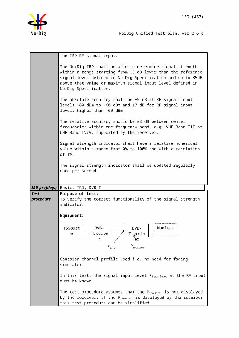
159 (457)
NorDig Unified Test plan, ver 2.6.0
K35 586 8K36 594 8K37 602 8K38 610 8K39 618 8K40 626 8K41 634 8K42 642 8K43 650 8K44 658 8K45 666 8K46 674 8K47 682 8K48 690 8K49 698 8K50 706 8K51 714 8K52 722 8K53 730 8K54 738 8K55 746 8K56 754 8K57 762 8K58 770 8K59 778 8K60 786 8K61 794 8K62 802 8K63 810 8K64 818 8K65 826 8K66 834 8K67 842 8K68 850 8K69 858 8
Table 1. Mandatory center frequencies and signal bandwidths to receive
Band Channel Frequency [MHz]
BW [MHz]
Result OK or NOK
VHF III
5A 174.928 1.75B 176.640 1.75C 178.352 1.75D 180.064 1.76A 181.936 1.76B 183.648 1.76C 185.360 1.76D 187.072 1.77A 188.928 1.77B 190.640 1.77C 192.352 1.77D 194.064 1.78A 195.936 1.78B 197.648 1.78C 199.360 1.78D 201.072 1.79A 202.928 1.79B 204.640 1.79C 206.352 1.79D 208.064 1.710A 209.936 1.710B 211.648 1.710C 213.360 1.710D 215.072 1.711A 216.928 1.711B 218.640 1.7
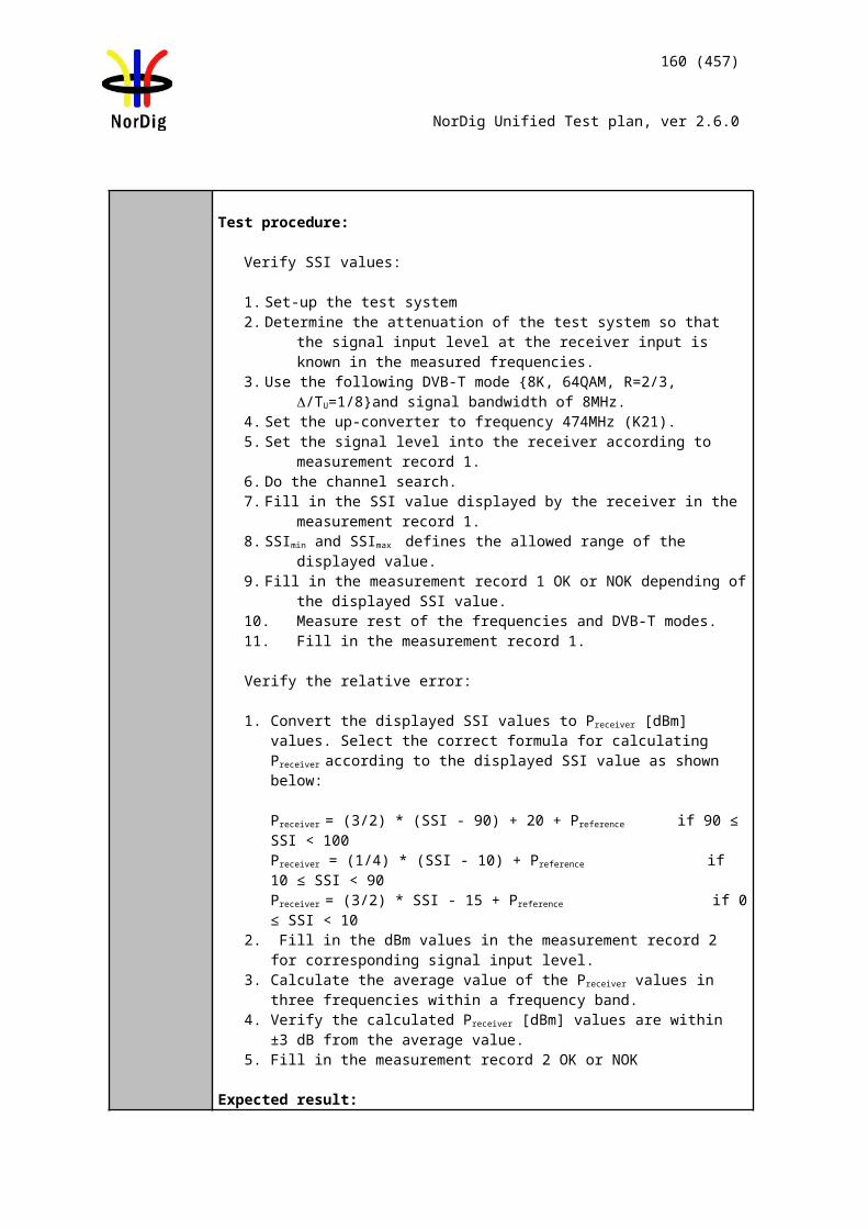
160 (457)
NorDig Unified Test plan, ver 2.6.0
11C 220.352 1.711D 222.064 1.712A 223.936 1.712B 225.648 1.712C 227.360 1.712D 229.072 1.713A 230.784 1.713B 232.496 1.713C 234.208 1.713D 235.776 1.713E 237.488 1.713F 239.200 1.7
Table 2. Optional center frequencies and 1.7MHz signal bandwidths to receive
Band Channel Frequency [MHz]
BW [MHz]
Result 7MHz OK or NOK
BW [MHz]
Result 8MHzOK or NOK
VHFS I
D1 114.0 7 8S2 114.5 7 8S3 121.5 7 8D2 122.0 7 8S4 128.5 7 8D3 130.0 7 8S5 135.5 7 8D4 138.0 7 8S6 142.5 7 8D5 146.0 7 8S7 149.5 7 8D6 154.0 7 8S8 156.5 7 8D7 162.0 7 8S9 163.5 7 8D8 170.0 7 8S10 170.5 7 8
VHF III
K5 177.5 7 8D9 178.0 7 8K6 184.5 7 8D10 186.0 7 8K7 191.5 7 8D11 194.0 7 8K8 198.5 7 8D12 202.0 7 8K9 205.5 7 8D13 210.0 7 8K10 212.5 7 8D14 218.0 7 8K11 219.5 7 8D15 226.0 7 8K12 226.5 7 8
VHFS II
S11 233.5 7 8D16 234.0 7 8S12 240.5 7 8D17 242.0 7 8S13 247.5 7 8D18 250.0 7 8S14 254.5 7 8D19 258.0 7 8S15 261.5 7 8D20 266.0 7 8S16 268.5 7 8D21 274.0 7 8S17 275.5 7 8D22 282.0 7 8S18 282.5 7 8S19 289.5 7 8D23 290.0 7 8

TS source DVB-T2 exciter
DVB-T2 receiver
161 (457)
NorDig Unified Test plan, ver 2.6.0
S20 296.5 7 8D24 298.0 7 8
Table 3 Optional VHF center frequencies and signal bandwidths to receive.
Band Channel Frequency [MHz]
BW [MHz]
Result OK or NOK
UHFS III
S21 306.0 8S22 314.0 8S23 322.0 8S24 330.0 8S25 338.0 8S26 346.0 8S27 354.0 8S28 362.0 8S29 370.0 8S30 378.0 8S31 386.0 8S32 394.0 8S33 402.0 8S34 410.0 8S35 418.0 8S36 426.0 8S37 434.0 8S38 442.0 8S39 450.0 8S40 458.0 8S41 466.0 8
Table 4 Optional UHF center frequencies and signal bandwidth to receive.
Conformity OK Fault Major Minor, define fail reason in commentsComments If possible describe if fault can be fixed with software update: YES NO
Describe more specific faults and/or other information
Date Sign
Test Case Task 3:34 DVB-T2: Frequencies: Frequency offset
Section NorDig Unified 3.4.2.3Requirement The NorDig IRD shall be able to receive signals with an offset of up to 50kHz from the
nominal frequency.
IRD Profile(s) Basic, IRD, DVB-T2Test procedure Purpose of test:
To verify that the reception is possible in specified frequency offset from nominal frequency.
Equipment:
Use following DVB-T2 modes:
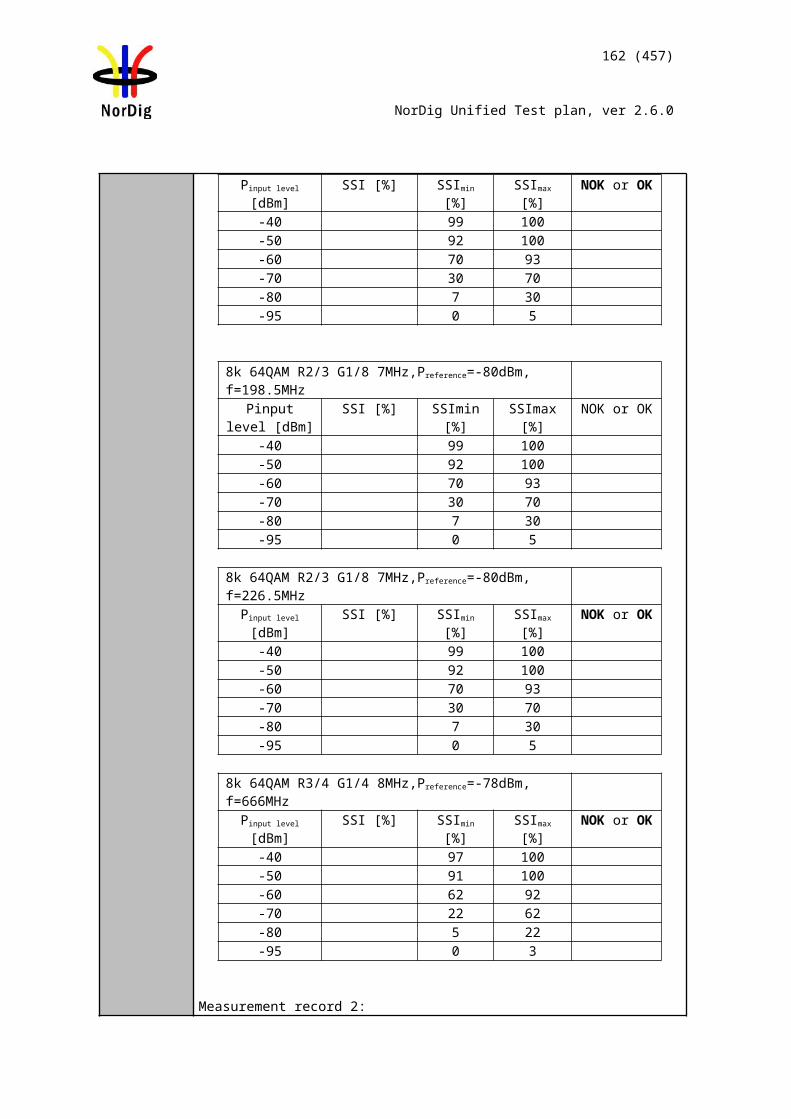
162 (457)
NorDig Unified Test plan, ver 2.6.0
VHF III 1.7 MHz signal bandwidth: 8k normal bandwidth, 64QAM rotated, G1/8, PP2, R2/3, L1-ACE & TR PAPR
VHF III 7 MHz signal bandwidth: 32k normal bandwidth, 256QAM rotated, GI1/8, PP2, R3/4, L1-ACE & TR PAPR
UHF IV/V 8 MHz signal bandwidth: 32k extended bandwidth, 256QAM rotated, GI1/16, PP4, R2/3, L1-ACE & TR PAPR
Test procedure:1. Set up the test instruments2. Set the center frequency to 177.5 MHz and frequency offset to 0 kHz. Use signal
bandwidth 7MHz. 3. Use the corresponding DVB-T2 mode from the list above. 4. Use input level of -50 dBm5. Connect receiver and do the channel search if needed.6. Test with the specified frequency offset values in the measurement record. Before
changing the frequency offset, disconnect the receiver from the received RF signal.
7. Do the change of frequency offset, 8. Connect the received RF signal back to the receiver. 9. Use the quality measurement procedure 1 (QMP1)10. Fill the result in the measurement record: OK or NOK.11. Test the remaining frequency offset values on specified center frequencies and
signal bandwidths in the measurement record.
Expected result:The test shall be OK for all frequency offset values on specified center frequencies and signal bandwidths in table 1 in test results.
Test result(s)Channel Signal BW
[MHz]Frequency
[MHz]Offset[kHz]
ResultOK or NOK
K57 177.5 -507 177.5 07 177.5 +50
K127 226.5 -507 226.5 07 226.5 +50
K218 474.0 -508 474.0 08 474.0 +50
K698 858.0 -508 858.0 08 858.0 +50
Table 1. Mandatory center frequency offsets to receive.
Channel Signal BW[MHz]
Frequency[MHz]
Offset[kHz]
ResultOK or NOK
5A1.7 174.928 -501.7 174.928 01.7 174.928 +50
13F1.7 239.200 -501.7 239.200 01.7 239.200 +50
Table 2. Optional center frequency offsets to receive.
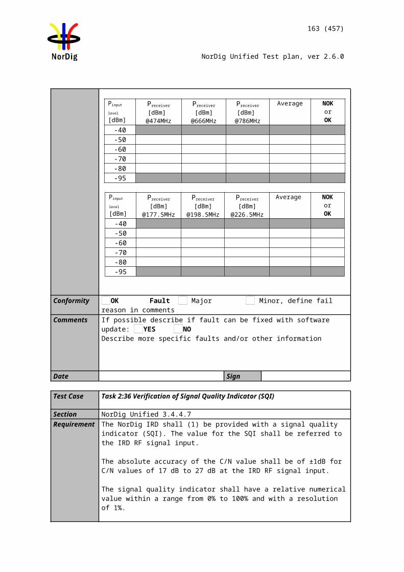
TS source DVB-T2 exciter
DVB-T2 receiver
163 (457)
NorDig Unified Test plan, ver 2.6.0
Conformity OK Fault Major Minor, define fail reason in commentsComments If possible describe if fault can be fixed with software update: YES NO
Describe more specific faults and/or other information
Date Sign
Test Case Task 3:35 DVB-T2: Frequencies: Signal bandwidths
Section NorDig Unified 3.4.2.4Requirement
The NorDig IRD for DVB-T2 shall support both the normal and extended carrier modes.
The NorDig IRD for DVB-T2 shall follow network parameter change from normal to extended carrier mode and vice versa automatically without any need for user action.
VHF Bands: The NorDig IRD shall (1) for the supported frequency ranges be able to receive 7 MHz and should be able to receive 8 MHz DVB-T/T2 signals. If 8 MHz bandwidth is supported it shall automatically detect which DVB-T/T2 signal bandwidth is being used, and it shall be possible to receive the 8 MHz DVB-T/T2 signals on the 7 MHz channel frequency raster.If 1.7 MHz bandwidth is supported the NorDig IRD-T2 shall automatically detect which DVB-T/T2 signal bandwidth is being used.
UHF Bands:The NorDig IRD shall for the supported frequency ranges be able to receive 8 MHz DVB-T/T2 signals.
IRD Profile(s) Basic, IRD, DVB-T2Test procedure Purpose of test:
To verify that the receiver is able to automatically detect the transmitted signal bandwidth and do the required adaptations for QEF reception.
Equipment:
Use following DVB-T2 modesin single PLP mode:
VHF III 1.7 MHz signal bandwidth: 8k normal bandwidth, 64QAM rotated, G1/8, PP2, R2/3, L1-ACE & TR PAPR
VHF III 7 MHz signal bandwidth: 32k normal or extended bandwidth, 256QAM rotated, GI19/256, PP2, R2/3, L1-ACE & TR PAPR
VHF III 8 MHz signal bandwidth: 32k extended bandwidth, 256QAM rotated, GI19/256, PP2, R3/5, L1-ACE & TR PAPR
UHF IV/V 8 MHz signal bandwidth: 32k normal or extended bandwidth, 256QAM rotated, GI1/16, PP4, R2/3, L1-ACE & TR PAPR
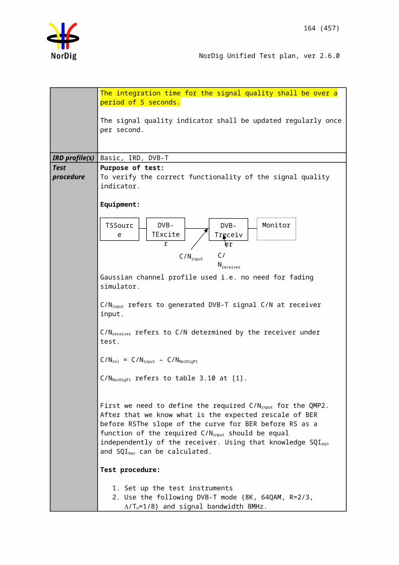
164 (457)
NorDig Unified Test plan, ver 2.6.0
Test procedure:
1. Set up the test instruments.2. Use the transmission frequency UHF IV/V 666 MHz (K45) and an input level of -
50 dBm to the receiver. Select corresponding DVB-T2 mode from list above.3. Connect the receiver and perform an automatic or manual channel search. The
signal bandwidth initialization shall not be required by the user. 4. Use the quality measurement procedure 1 (QMP1).5. Fill the result in the measurement record: OK or NOK.6. Change the transmission frequency to VHF III channel 198.5 MHz (K8) and signal
bandwidth to 7 MHz. Select corresponding DVB-T2 mode from list above.7. Verify that the channel list does not have any services installed by performing
initialization to factory defaults or in such way.8. Do an automatic or manual channel search. The signal bandwidth initialization
shall not be required by the user.9. Use the quality measurement procedure 1 (QMP1).10. Fill the result in the measurement record: OK or NOK.11. If receiver supports 1.7MHz signal bandwidth in VHF III, change the transmission
frequency to VHF III channel 209.936 MHz (10A) and signal bandwidth to 1.7 MHz. Select corresponding DVB-T2 mode from list above.
12. Verify that the channel list does not have any services installed by performing initialization to factory defaults or in such way.
13. Do an automatic or manual channel search. The signal bandwidth initialization shall not be required by the user.
14. Use the quality measurement procedure 1 (QMP1).15. If receiver supports 8MHz signal bandwidth in VHF III, change the transmission
frequency to VHF III channel 198.5 MHz (K8) and signal bandwidth to 8 MHz. Select corresponding DVB-T2 mode from list above.
Expected result:The test results shall be OK for all tests in the table 1 and table 2 in the measurement record and user does not have to initialize the signal bandwidth for the succesfull channel search and QEF reception.
If 1.7MHz signal bandwidth in VHF is supported the test result shall be OK for the test in the table 3 in the test reults.
If 8MHz signal bandwidth in VHF is supported the test result shall be OK for the test in the table 3 in the test results.
Test result(s) Measurement record:
Channel Frequency[MHz]
Signal bandwidth[MHz]
ResultOK or NOK
K8 198.5 7K45 666.0 8
Table 1 Mandatory signal bandwidths to receive for normal carrier mode.
Channel Frequency[MHz]
Signal bandwidth[MHz]
ResultOK or NOK
K8 198.5 7K45 666.0 8
Table 2 Mandatory signal bandwidths to receive for extended carrier mode
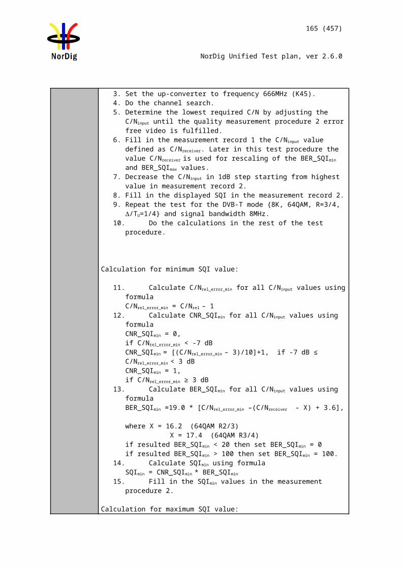
165 (457)
NorDig Unified Test plan, ver 2.6.0
Channel Frequency[MHz]
Signal bandwidth[MHz]
ResultOK or NOK
10A 209.936 1.7Table 3 Optional signal bandwidth to receive for normal carrier mode.
Channel Frequency[MHz]
Signal bandwidth[MHz]
ResultOK or NOK
K8 198.5 8Table 4 Optional signal bandwidths to receive for extended carrier mode
Conformity OK Fault Major Minor, define fail reason in commentsComments If possible describe if fault can be fixed with software update: YES NO
Describe more specific faults and/or other information
Date Sign
Test Case Task 3:36 DVB-T2: Modes
Section NorDig Unified 3.4.3Requirement The NorDig IRD-T2 shall be capable of correctly demodulating all allowed configurations,
or “DVB-T2 modes”, as specified in EN 302 755, with the following exceptions: Support for 1.7 MHz bandwidth is optional
Support for Time Frequency Slicing (TFS) is optional.
Support for 10 MHz bandwidth is not required
Support for PLPs carrying GS/GSE is not required
Support for Transmission modes 16K and 32K, when 1.7 MHz RF bandwidth is supported, is not required
The existence of transmissions using configurations that the NorDig IRD-T2 is not required to support shall not cause the NorDig IRD-T2 to malfunction.
When TFS is supported the following shall apply: For 8MHz DVB-T2 signals with modulation parameters {32K, 256-QAM, CR=3/5, GI=1/16} on all data PLPs the NorDig IRD-T2 shall support reception of variable-bit rate PLPs in TFS with a TS peak data rate of up to 15 Mbps using up to six RF frequencies. Each TS is split into one data PLP and a common PLP.
The NorDig IRD shall automatically detect which mode is being used.IRD Profile(s) Basic, IRD, DVB-T2Test procedure Purpose of test:
To verify the reception of subset of all possible DVB-T2 modes.
TFS support is not tested.
MISO support is not tested.
FEC frame length 16200 is not tested.
Input Mode B is not tested.
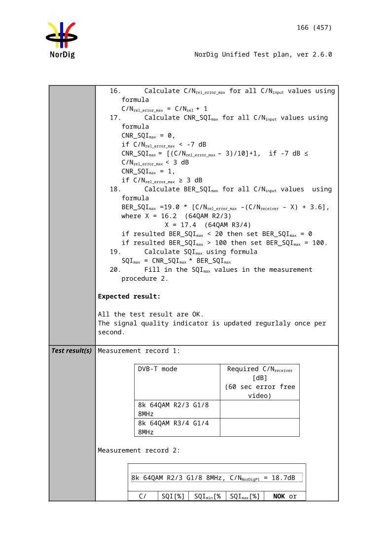
TS source DVB-T2 exciter
DVB-T2 receiver
166 (457)
NorDig Unified Test plan, ver 2.6.0
Normal mode (NM) is not tested.
Extended and normal carrier modes are tested in test Task 3:35 DVB-T2 Frequencies: Bandwidth
Equipment:
Use Mode A (Single PLP) and following deviations to parameter settings defined in 2.3.7Summary of DVB-T2 modes in DVB-T2 test tasks:
Carrier mode NormalSignal bandwidth 8MHz
Test procedure:
1. Set up the test instruments.2. Use channel K45 (666MHz) and an input level of -50 dBm.3. Test all the DVB-T2 parameter combinations listed in tables in test results using
the quality measurement procedure 1 (QMP1).4. Fill the result in the measurement record: OK or NOK.
Expected result:The test shall be OK for all tested DVB-T2 mode parameter listed in test result tables.
Test result(s) Measurement record:FFT NOK or OK
64QAM rotated, GI1/8, PP2, R2/3, L1-ACE & TR PAPR, Lf= 90 1k
64QAM rotated, GI1/8, PP2, R2/3, L1-ACE & TR PAPR, Lf= 90 2k
64QAM rotated, GI1/8, PP2, R2/3, L1-ACE & TR PAPR, Lf= 90 4k
64QAM rotated, GI1/8, PP2, R2/3, L1-ACE & TR PAPR, Lf= 90 8k
64QAM rotated, GI1/8, PP2, R2/3, L1-ACE & TR PAPR, Lf= 90 8k ext
256QAM rotated, GI1/8, PP2, R2/3, L1-ACE & TR PAPR, Lf= 90 16k
256QAM rotated, GI1/8, PP2, R2/3, L1-ACE & TR PAPR, Lf= 90 16k ext
256QAM rotated, GI1/8, PP2, R3/4, L1-ACE & TR PAPR, Lf= 60 32k
256QAM rotated, GI1/8, PP2, R3/4, L1-ACE & TR PAPR, Lf= 60 32k ext
Table 1 FFT sizes
Rotation NOK or OK
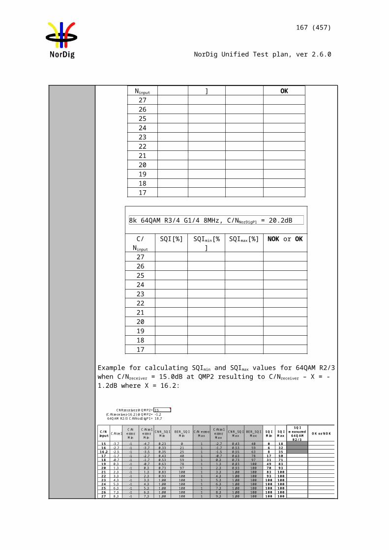
167 (457)
NorDig Unified Test plan, ver 2.6.0
32k, 256QAMGI1/16, PP4,R2/3,L1-ACE & TR PAPR,Lf=62
Rotated
Non-rotated
Table 2 Constellation rotation
Pilot pattern NOK or OK16k,256QAM rotated,GI1/4,R2/3,L1-ACE & TR PAPR,Lf= 90 PP1
32k,256QAM rotated,GI1/8,R3/4,L1-ACE & TR PAPR,Lf= 60 PP2
16k,256QAM rotated,GI1/8,R2/3,L1-ACE & TR PAPR,Lf= 90 PP3
32k,256QAM rotated,GI1/16,R2/3,L1-ACE & TR PAPR,Lf= 62 PP4
16k,256QAM rotated,G1/16,R2/3,L1-ACE & TR PAPR,Lf= 90 PP5
32k,256QAM rotated,GI1/32,R3/5,L1-ACE & TR PAPR,Lf= 62 PP6
32k,256QAM rotated,GI1/128,R2/3,L1-ACE & TR PAPR,Lf= 60 PP7
32k,256QAM rotated,GI1/16,R3/4,L1-ACE & TR PAPR,Lf= 62 PP8
Table 3 Pilot patterns
NOK or OKL1-ACE & TR PAPR, rotated constellation32K, PP7,Lf= 60
32K, PP4, Lf= 60
32K, PP2, Lf= 60
32K, PP2, Lf= 60
32K, PP2, Lf= 60
32K, PP2, Lf= 60
8K, PP1 Lf= 60
Modulation FEC 1/128 1/32 1/16 19/256 1/8 19/128 1/4QPSK 1/2QPSK 3/5QPSK 2/3QPSK 3/4QPSK 4/5QPSK 5/616-QAM 1/216-QAM 3/516-QAM 2/316-QAM 3/416-QAM 4/516-QAM 5/664-QAM 1/264-QAM 3/564-QAM 2/364-QAM 3/464-QAM 4/564-QAM 5/6
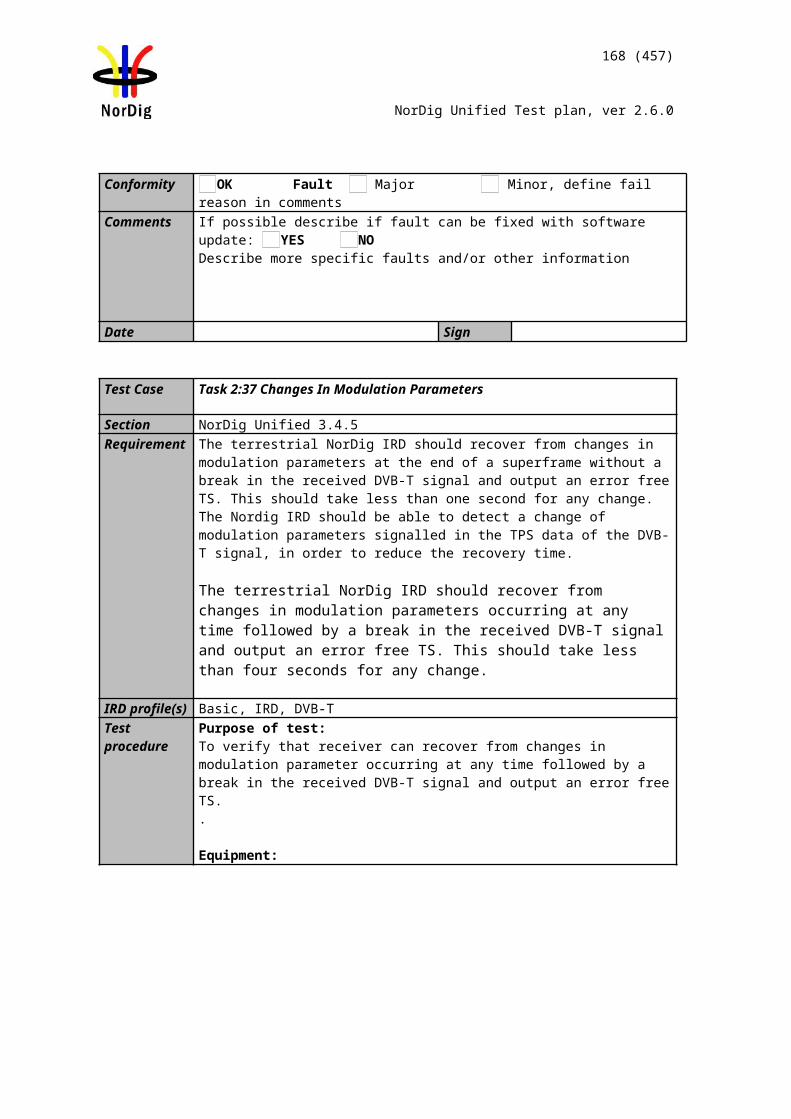
Channel B
T2MIsource
DVB-T2 receiver
DVB-T2 exciter 1
ATT C2
ATT C1
DVB-T/T2 exciter 2
Channel A
Noise
168 (457)
NorDig Unified Test plan, ver 2.6.0
256-QAM 1/2256-QAM 3/5256-QAM 2/3256-QAM 3/4256-QAM 4/5256-QAM 5/6
Table 4 Guard intervals, constellations and code rates for allowed combinations of FFT sizes, pilot patterns and L1-ACE & TR PAPR.
PAPR L1_ACE_MAX NOK or OK
32k normal, 256QAM non-rotatedGI1/8, PP2,R3/4
L1-ACE and P2-TR 0L1-ACE and ACE only 0L1-ACE and TR only 0L1-ACE, ACE and TR 0Not used N/A
Table 5 Peak-to-average power ratio (PAPR)
Conformity OK Fault Major Minor, define fail reason in commentsComments If possible describe if fault can be fixed with software update: YES NO
Describe more specific faults and/or other information
Date Sign
Test Case Task 3:37 DVB-T2: MISO
Section NorDig Unified 3.4.3Requirement Within the NorDig IRD specification the concept of “DVB-T2 mode” includes e.g. (the list
is not exhaustive): SISO/MISO
IRD Profile(s) Basic, IRD, DVB-T2Test procedure Purpose of test:
To verify that the receiver fully supports the expected advantages of MISO transmissions modes in SFN.
Equipment:
T2MI source shall have a TS containing at least one service.
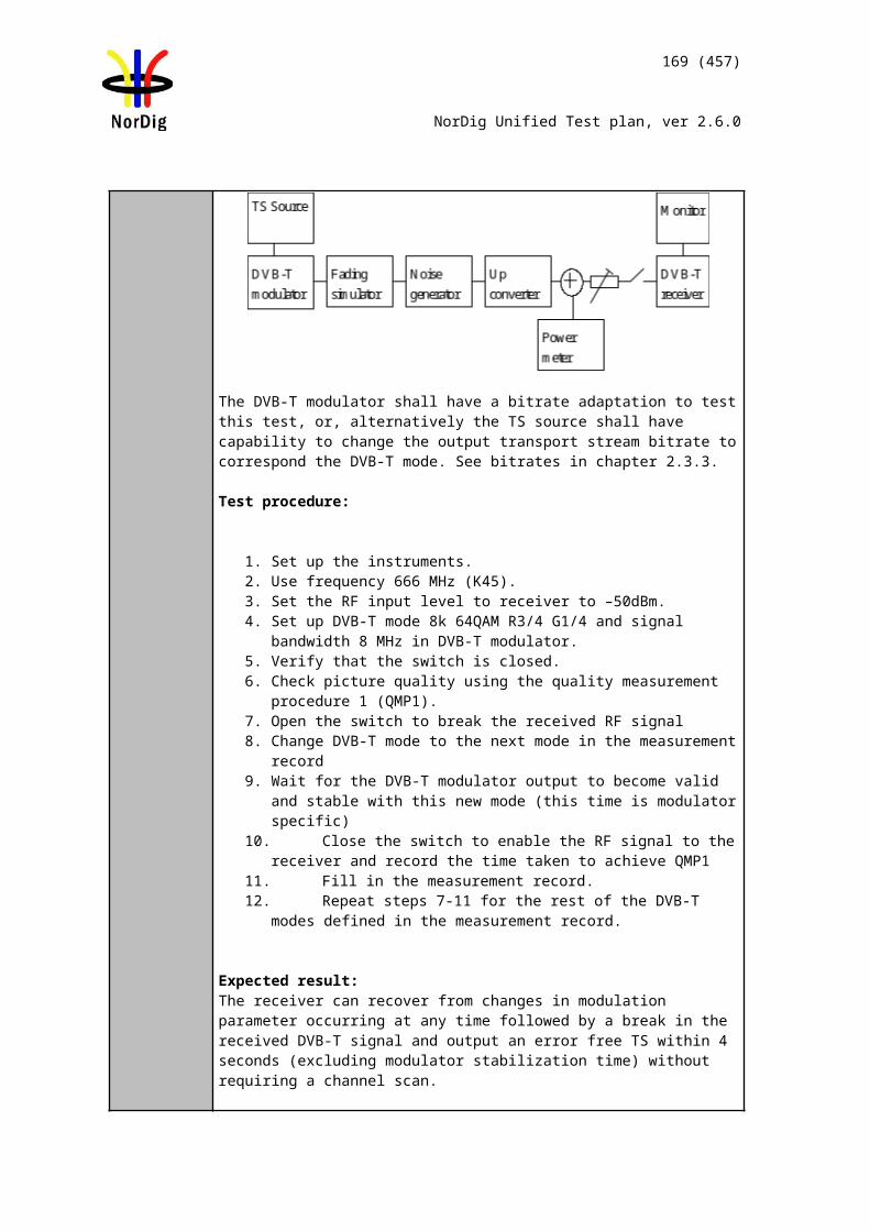
169 (457)
NorDig Unified Test plan, ver 2.6.0
Use Mode A (Single PLP) and following deviations to parameter settings defined in 2.3.7 Summary of DVB-T2 modes in DVB-T2 test tasks:
SISO/MISO MISO
Both DVB-T2 exciters must be locked to same reference signals as well as run in the SFN mode.
Test procedure:
First verify reception in Gaussian like channel when exciters are in MISOmodes with different group settings.
1. Set up the test instruments2. Set the channel A to 666.0MHz (K45).3. Set the channel B to 666.0MHz (K45).4. Set the DVB-T2 exciter in channel A to MISO group 1 mode with parameters 8
MHz signal bandwidth, 32k extended, 256QAM rotated, GI1/16, PP2, R2/3, L1-ACE & TR PAPR, Lf= 62.
5. Set the DVB-T2 exciter in channel B to MISO group 2 mode with parameters 8MHz signal bandwidth, 32k extended, 256QAM rotated, GI1/16, PP2, R2/3, L1-ACE & TR PAPR, Lf=62.
6. Set the receiver input level for the DVB-T2 signal in channel A to -50 dBm. Attenuate the input signal from channel B so that it is not able to be received.
7. Adjust the noise power to a level corresponding 30dB signal-to-noise ratio. 8. Verify the service carried on channel A is able to be received and decoded
correctly using quality measurement procedure 1(QMP1).9. Fill in NOK or OKin measurement record. 10. Increase the attenuation for the channel A so that it is not any more able to be
received.11. Decrease the attenuation for the channel B. Adjust the receiver input level to -
50dBm.12. Verify the service carried on channel Bis able to be received and decoded correctly
using quality measurement procedure 1 (QMP1).13. Fill in NOK or OKin measurement record.
Secondly verify reception in SFN like channels in MISO modes with different group settings.
14. Set the DVB-T2 exciter in channel A to MISO group 1 mode with parameters 8 MHz signal bandwidth, 32k extended, 256QAM rotated, GI1/16, PP2, R2/3, L1-ACE & TR PAPR, Lf= 62.
15. Set relative delay of the exciters to 10µs, adjust output levels to 0dB echo difference and verify the total output power level is -50dBm as well as noise power to a level corresponding 30dB signal-to-noise ratio.
16. Verify the service carried on channel A is able to be received and decoded correctly using quality measurement procedure 1 (QMP1).
17. Fill in NOK or OKin measurement record.18. Set the relativedelay of the exciters to 170µs and output power level difference to
0dB. 19. Verify the service carried on channel A is able to be received and decoded
correctly using quality measurement procedure 1 (QMP1).20. Fill in NOK or OKin measurement record.
Thirdly verify reception in SFN like channels in MISO modes with equal group settings.
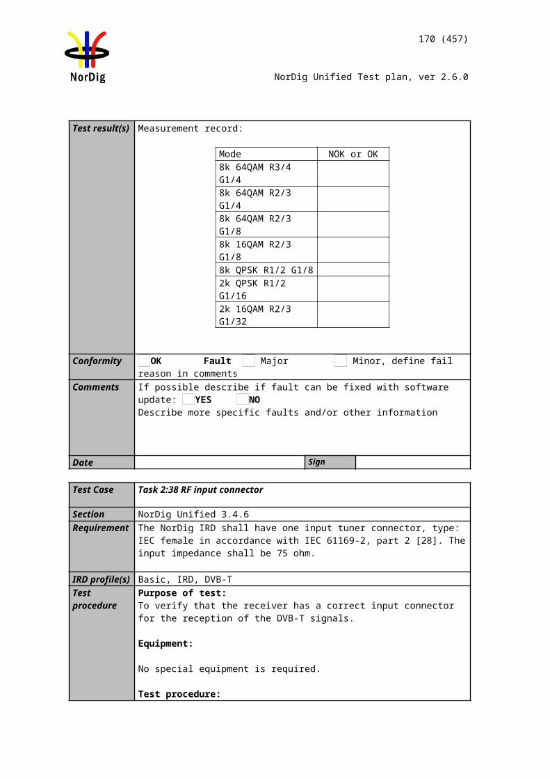
170 (457)
NorDig Unified Test plan, ver 2.6.0
21. Set the DVB-T2 exciters in channel A and B to MISO group 2 1)mode with parameters 8 MHz signal bandwidth, 32k extended, 256QAM rotated, GI1/16, PP2, R2/3, L1-ACE & TR PAPR, Lf= 62.
22. Set relative delay of the exciters to 10µs, adjust output levels to 0dB echo difference and verify the total output power level is -50dBm as well as noise power to a level corresponding 30dB signal-to-noise ratio.
23. Verify the service carried on is able to be received and decoded correctly using quality measurement procedure 1 (QMP1).
24. Fill in NOK or OKin measurement record.25. Set the relative delay of the exciters to 170µs and output power level difference to
0dB. 26. Verify the service carried on is able to be received and decoded correctly using
quality measurement procedure 1 (QMP1).27. Fill in NOK or OKin measurement record.
1)Consider reception in SFN consisting three or more transmitters. Because of group settings in exciters, reception from exciters within same group or different groupsmay occur.
Expected result:The IRD is able to decode services correctly and all the test results are OK.
Test result(s)Measurement record
Exciter 1 Exciter 2 Channelprofile
NOK or OK
MISO group 1 - Gaussian - MISO group 2 Gaussian MISO group 1 MISO group 2 10µs 0dB echoMISO group 1 MISO group 2 170µs 0dB echoMISO group 2 MISO group 2 10µs 0dB echoMISO group 2 MISO group 2 170µs 0dB echo
Conformity OK Fault Major Minor, define fail reason in commentsComments If possible describe if fault can be fixed with software update: YES NO
Describe more specific faults and/or other information
Date Sign
Test Case Task 3:38 DVB-T2: Input Mode B (multiple PLPs)
Section NorDig Unified 3.4.3Requirement Within the NorDig IRD specification the concept of “DVB-T2 mode” includes e.g. (the list
is not exhaustive): Input Mode A (single PLP) or Input Mode B (Multiple PLPs – Common PLP,
Type 1 and 2 up to the maximum allowed figure 255)IRD Profile(s) Basic, IRD, DVB-T2Test procedure Purpose of test:
To verify that receiver supports input mode B with multiple PLPs without common PLP.
171 (457)
NorDig Unified Test plan, ver 2.6.0
Equipment:
Use Mode B (Multiple PLP) parameter settings defined in 2.3.7Summary of DVB-T2 modes in DVB-T2 test tasks.
The DVB-T2 exciter is configured with parameters 8 MHz signal bandwidth, 32k extended, 256QAM rotated, GI1/16, PP4, R2/3, L1-ACE & TR PAPR, Lf= 62.
In figure above a T2GW is producing the T2MI signal with multiple PLPs. Another equipment can be used as well supporting multiple PLPs.
TS1 is broadcasted as PLP1.TS2 is broadcasted as PLP2.
Both TSs carry services able to be decoded in IRD.
Test procedure:
1. Configure the system 2. Make automatic channel search in the IRD3. Verify the service carried with TSs are decoded in the IRD
Expected result:
IRD is able to decode services carried within TS1 and TS2 correctly.
Test result(s)
Conformity OK Fault Major Minor, define fail reason in commentsComments If possible describe if fault can be fixed with software update: YES NO
Describe more specific faults and/or other information
Date Sign
Test Case Task 3:39 DVB-T2: Input Mode B (multiple PLPs and common PLP)
Section NorDig Unified 3.4.3Requirement Within the NorDig IRD specification the concept of “DVB-T2 mode” includes e.g. (the list
is not exhaustive):Input Mode A (single PLP) or Input Mode B (Multiple PLPs – Common PLP, Type 1 and 2 up to the maximum allowed figure 255)
IRD Profile(s) Basic, IRD, DVB-T2Test procedure Purpose of test:
T2GW DVB-T2exciter
IRDTS1
TS2
T2MI PLP1
PLP2
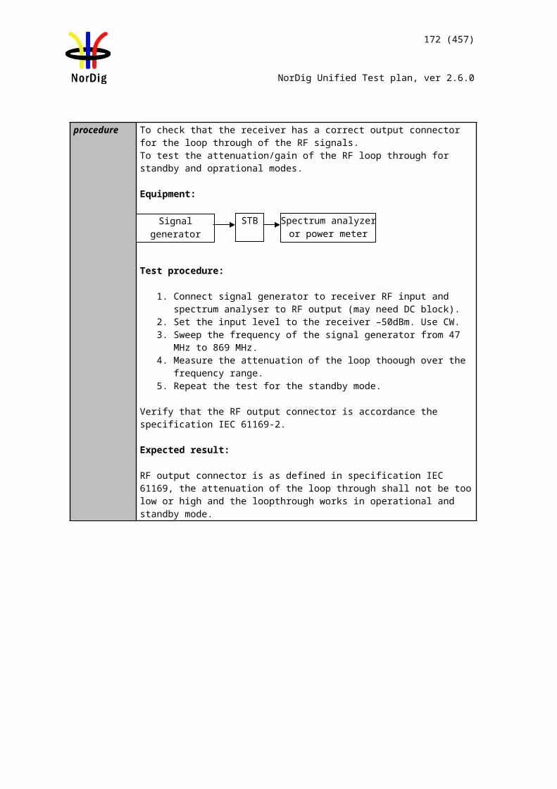
172 (457)
NorDig Unified Test plan, ver 2.6.0
To verify that receiver supports input mode B with multiple PLPs and common PLP.
Equipment:
Use Mode B (Multiple PLP) parameter settings defined in 2.3.7Summary of DVB-T2 modes in DVB-T2 test tasks.
The DVB-T2 exciter is configured with parameters 8 MHz signal bandwidth, 32k extended, 256QAM rotated, GI1/16, PP4, R2/3, L1-ACE & TR PAPR, Lf= 62.
In figure above a T2GW is producing the T2MI signal with multiple PLPs. Another equipment can be used as well supporting multiple PLPs.
The PLP0 corresponds common PLP and carries information equipment supports. In this test the common information is EIT which content can be verified in IRD.
PLP0 carries the PSI/SI TS1 is broadcasted as PLP1.TS2 is broadcasted as PLP2.
Both TSs carries services and EIT able to be decoded in IRD.
Test procedure:
1. Configure the system 2. Make automatic channel search in the IRD3. Verify the service carried with TSs are decoded in the IRD
Expected result:IRD is able to decode services carried within TS1 and TS2 correctly and present EIT information correctly.
Test result(s)
Conformity OK Fault Major Minor, define fail reason in commentsComments If possible describe if fault can be fixed with software update: YES NO
Describe more specific faults and/or other information
Date Sign
Test Case Task 3:40 DVB-T2: Input Mode B (RBM for TDI)
Section NorDig Unified 3.4.3Requirement Within the NorDig IRD specification the concept of “DVB-T2 mode” includes e.g. (the list
is not exhaustive): Input Mode A (single PLP) or Input Mode B (Multiple PLPs – Common PLP,
T2GW DVB-T2exciter
IRDTS1
TS2
T2MI PLP0
PLP1
PLP2
173 (457)
NorDig Unified Test plan, ver 2.6.0
Type 1 and 2 up to the maximum allowed figure 255)
DVB-T2 signal introduces a receiver buffer model (RBM) which is fundamental when it comes to receive signals where carried transport stream doesn’t have constant bit rate as it is case for MPLPs.
IRD Profile(s) Basic, IRD, DVB-T2Test procedure Purpose of test:
To verify that received DVB-T2 signal can stress the receiver RBM regarding time deinterleaver buffer based on DVB V&V tests.
Equipment:
Use Mode B (multiple PLP) and parameter settings defined in 2.3.7 Summary of DVB-T2 modes for NU_M2.
T2 frames within PLPid=0 and 1 shall carry a valid TS. TS bit rate is restricted to maximum of 3.3 MBit/s.
The content within TS is maximized to bit rate the TS can carry, with other words, minimize the NULL packets in TS.
TS contains one service.
The DVB-T2 signal generation shall support DVB V&V dynamic multiple PLP models. The configuration files are available for download on NorDig homepages.
Parameter Description ValueM Interval in packets between common PLP
slots22
L Number of separate chapters 4NumReps Repeats of repeating unit 15, 1, 15, 1RunLength (TS0) Run length for TS0 in each repeating unit
in a chapter 92, 20, 44, 27
RunLength (TS1) Run length for TS1 in each repeating unit in a chapter
44, 27, 92, 20
RunLength (TS2) Run length for TS2 in each repeating unit in a chapter
8, 2, 8, 2
RunLength (TS3) Run length for TS3 in each repeating unit in a chapter
8, 2, 8, 2
Test procedure:
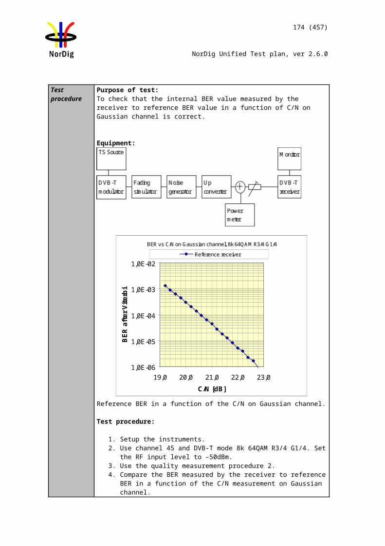
174 (457)
NorDig Unified Test plan, ver 2.6.0
1. Set up the test instruments.2. Use the following DVB-T2 mode {32K extended, 256QAM, PP7, /TU=1/128}
and signal bandwidth 8MHz in exciter. 3. Use Gaussian channel without additional noise or interference.4. Set the receiver input level to -50 dBm.5. Verify valid TS is mapped into the PLPid=0.6. Perform channel search and make sure the receiver has deleted any possible old
service on the channel list.7. Verify the received signal carrying service using quality measurement procedure 2
(QMP2).8. Repeat the test for a valid TS mapped into the PLPid=1.
Expected result:
Broadcasting of DVB-T2 signal according to signal description which stresses the RBM is demodulated correctly and service carried within TS is decoded error free.
Test result(s)
Conformity OK Fault Major Minor, define fail reason in commentsComments If possible describe if fault can be fixed with software update: YES NO
Describe more specific faults and/or other information
Date Sign
Test Case Task 3:41 DVB-T2: Input Mode B (RBM for DJB)
Section NorDig Unified 3.4.3Requirement Within the NorDig IRD specification the concept of “DVB-T2 mode” includes e.g. (the list
is not exhaustive): Input Mode A (single PLP) or Input Mode B (Multiple PLPs – Common PLP,
Type 1 and 2 up to the maximum allowed figure 255)
DVB-T2 signal introduces a receiver buffer model (RBM) which is fundamental when it comes to receive signals where carried transport stream doesn’t have constant bit rate as it is case for MPLPs.
IRD Profile(s) Basic, IRD, DVB-T2Test procedure Purpose of test:
To verify that received DVB-T2 signal can stress the receiver RBM regarding de-jitter buffer based on DVB V&V tests.
Equipment:
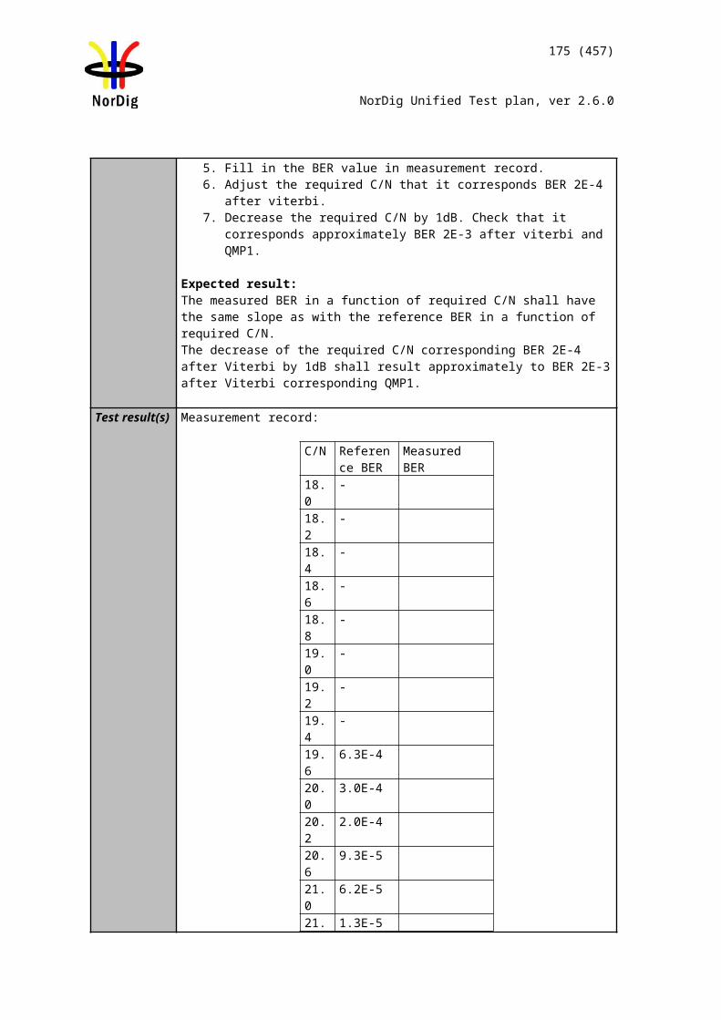
175 (457)
NorDig Unified Test plan, ver 2.6.0
Use Mode B (multiple PLP) and parameter settings defined in 2.3.7 Summary of DVB-T2 modes for NU_M3.
T2 frames within PLPid=0 and 2 shall carry a valid TS. TS bit rate is restricted to maximum of 3.3 MBit/s.
The content within TS is maximized to bit rate the TS can carry, with other words, minimize the NULL packets in TS.
TS contains one service.
The DVB-T2 signal generation shall support DVB V&V dynamic multiple PLP models.The configuration files are available for download on NorDig homepages.
Parameter Description ValueM Interval in packets between common PLP
slots11
L Number of separate chapters 8NumReps Repeats of repeating unit 15, 1, 15, 1,
15, 1, 15, 1, 15, 1
RunLength (TS0) Run length for TS0 in each repeating unit in a chapter
102, 95, 102, 95, 102, 95, 102, 95
RunLength (TS1) Run length for TS1 in each repeating unit in a chapter
15, 29, 15, 29, 15, 29, 15, 29
RunLength (TS2) Run length for TS2 in each repeating unit in a chapter
14, 15, 14, 15, 14, 15, 14, 15
RunLength (TS3) Run length for TS3 in each repeating unit in a chapter
14, 16, 14, 16, 14, 16, 14, 16
Test procedure:
1. Set up the test instruments.2. Use the following DVB-T2 mode {32K extended, 256QAM, PP7, /TU=1/128}
and signal bandwidth 8MHz in exciter. 3. Use Gaussian channel without additional noise or interference.4. Set the receiver input level to -50 dBm.5. Verify valid TS is mapped into the PLPid=0.6. Perform channel search and make sure the receiver has deleted any possible old
service on the channel list.7. Verify the received signal carrying service using quality measurement procedure 2
(QMP2).8. Repeat the test for TS mapped into the PLPid=2.
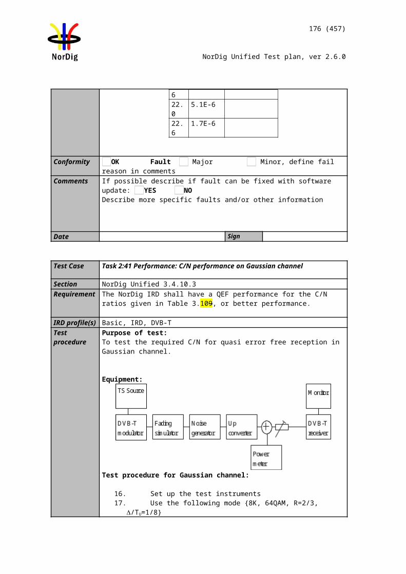
176 (457)
NorDig Unified Test plan, ver 2.6.0
Expected result:
Broadcasting of DVB-T2 signal according to signal description which stresses the RBM is demodulated correctly and service carried within TS is decoded error free.
Test result(s)
Conformity OK Fault Major Minor, define fail reason in commentsComments If possible describe if fault can be fixed with software update: YES NO
Describe more specific faults and/or other information
Date Sign
Test Case Task 3:42 DVB-T2: Input Mode B (RBM when FEF present)
Section NorDig Unified 3.4.3Requirement Within the NorDig IRD specification the concept of “DVB-T2 mode” includes e.g. (the list
is not exhaustive): Input Mode A (single PLP) or Input Mode B (Multiple PLPs – Common PLP,
Type 1 and 2 up to the maximum allowed figure 255)
DVB-T2 signal introduces a receiver buffer model (RBM) which is fundamental when it comes to receive signals where carried transport stream doesn’t have constant bit rate as it is case for MPLPs and FEF.
IRD Profile(s) Basic, IRD, DVB-T2Test procedure Purpose of test:
To verify that received DVB-T2 signal can stress the receiver RBM regarding time deinterleaver buffer based on DVB V&V tests.
Equipment:
Use Mode B (multiple PLP) and parameter settings defined in 2.3.7 Summary of DVB-T2 modes for NU_M4.
The DVB-T2 signal shall contain a FEF with PRBS content and with a FEF interval of 4 T2 frames.
The size of the PRBS FEF is 380000 samples and T2 frame size Lf=28 symbols.
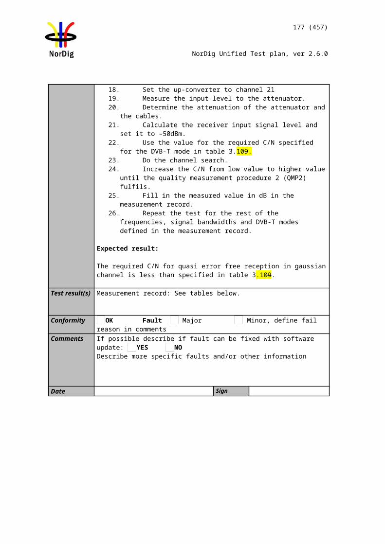
177 (457)
NorDig Unified Test plan, ver 2.6.0
T2 frames within PLPid=0 and 3 shall carry a valid TS. TS bit rate is restricted to maximum of 3.3MBit/s.
The content within TS is maximized to bit rate the TS can carry, with other words, minimize the NULL packets in TS.
TS contains one service.
The DVB-T2 signal generation shall support DVB V&V dynamic multiple PLP models.The configuration files are available for download on NorDig homepages.
Parameter Description ValueM Interval in packets between common PLP
slots11
L Number of separate chapters 10NumReps Repeats of repeating unit 15, 1, 15, 1,
15, 1, 15, 1, 15, 1
RunLength (TS0) Run length for TS0 in each repeating unit in a chapter
102, 95, 102, 95, 0, 0, 66, 3, 102, 95
RunLength (TS1) Run length for TS1 in each repeating unit in a chapter
13, 11, 13, 11, 19, 13, 8, 17, 13, 11
RunLength (TS2) Run length for TS2 in each repeating unit in a chapter
13, 15, 13, 15, 19, 13, 8, 15, 13, 15
RunLength (TS3) Run length for TS3 in each repeating unit in a chapter
13, 14, 13, 14, 18, 11, 7, 3, 13, 14
Test procedure:
1. Set up the test instruments.2. Use the following DVB-T2 mode {32K extended, 256QAM, PP7, /TU=1/128}
and signal bandwidth 8MHz in exciter. 3. Use Gaussian channel without additional noise or interference.4. Set the receiver input level to -50 dBm.5. Verify valid TS is mapped into the PLPid=0.6. Perform channel search and make sure the receiver has deleted any possible old
service on the channel list.7. Verify the received signal carrying service using quality measurement procedure 2
(QMP2).8. Repeat the test for a valid TS mapped into the PLPid=3.
Expected result:
Broadcasting of DVB-T2 signal according to signal description which stresses the RBM is demodulated correctly and service carried within TS is decoded error free.
Test result(s)
Conformity OK Fault Major Minor, define fail reason in commentsComments If possible describe if fault can be fixed with software update: YES NO
Describe more specific faults and/or other information
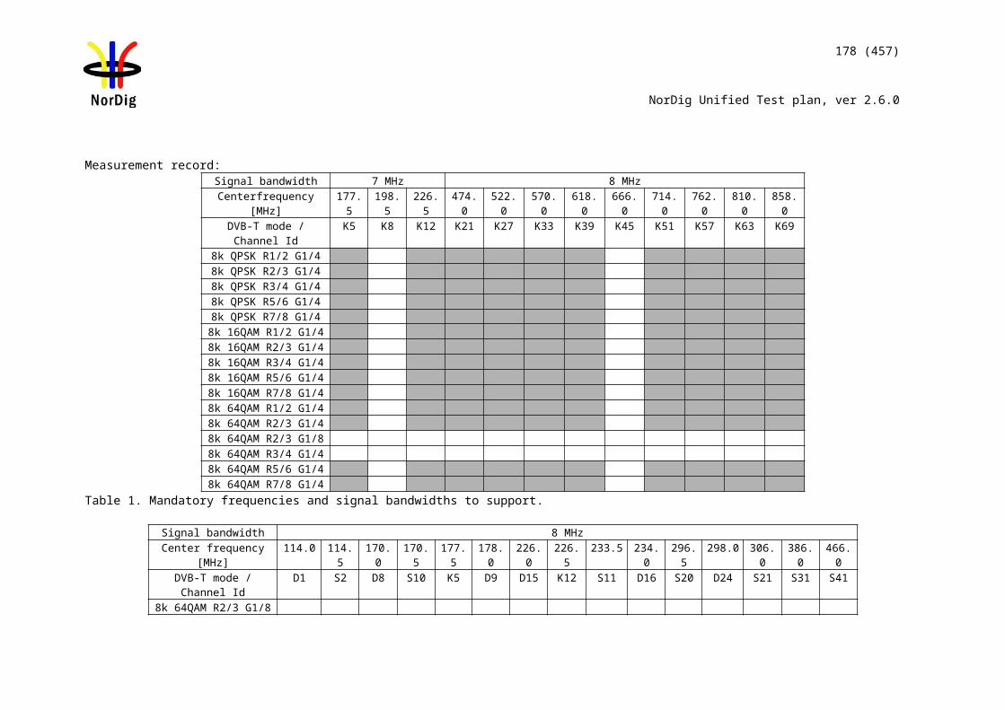
178 (457)
NorDig Unified Test plan, ver 2.6.0
Date Sign
Test Case Task 3:43 DVB-T2: Normal mode (NM)
Section NorDig Unified 3.4.3RequirementIRD Profile(s) Basic, IRD, DVB-T2Test procedure Purpose of test:
To verify that receiver supports normal mode (NM).
Equipment:
Use Mode A (Single PLP) and following deviations to parameter settings defined in 2.3.7Summary of DVB-T2 modes in DVB-T2 test tasks:
Mode NM
(normal mode)
ISSY Short
The DVB-T2 modulator is configured with parameters 8 MHz signal bandwidth, 32k extended, 256QAM rotated, GI1/16, PP4, R2/3, L1-ACE & TR PAPR, Lf= 62.
Test procedure:
1. Configure the system 2. Make automatic channel search in the IRD3. Verify the services carried with TS are decoded correctly in the IRD
Expected result:IRD is able to decode services carried within TS correctly.
Test result(s)
Conformity OK Fault Major Minor, define fail reason in commentsComments If possible describe if fault can be fixed with software update: YES NO
Describe more specific faults and/or other information
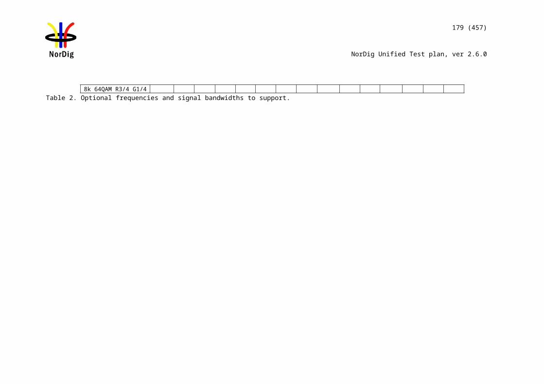
179 (457)
NorDig Unified Test plan, ver 2.6.0
Date Sign
Test Case Task 3:44 DVB-T2: Input Mode A (zero power FEF present)
Section NorDig Unified 3.4.3RequirementIRD Profile(s) Basic, IRD, DVB-T2Test procedure Purpose of test:
To verify that broadcasting of FEF doesn’t cause any harm for the receiver.
Equipment:
Use Mode A (Single PLP) and following deviations to parameter settings defined in 2.3.7 Summary of DVB-T2 modes in DVB-T2 test tasks:
ISSY EnabledFEF YesAuxiliary streams Not usedFrames per superframe (NT2) 6FEF P1: S1 Value 2FEF P1: S2 Value 1T2 P1:S2 Value 1FEF size 520000 samplesDesign delay 719248 samples
The DVB-T2 signal shall contain empty FEF with a FEF interval of 6 T2 frames.
The size of the empty FEF is 520000 samples (56.875ms) and T2 frame size Lf=62symbols (236.320ms). By empty FEF means FEF without content resulting to a lower RF output power during the FEF compared to T2 frame.
T2 frames shall carry a TS. TS bitrate is maximized to the capacity the T2 frame size can deliver, with other words, the number of T2 dummy cells are minimized.
The content within TS is maximized to bit rate the TS can carry, with other words, minimize the NULL packets in TS.
TS contains at least one service.
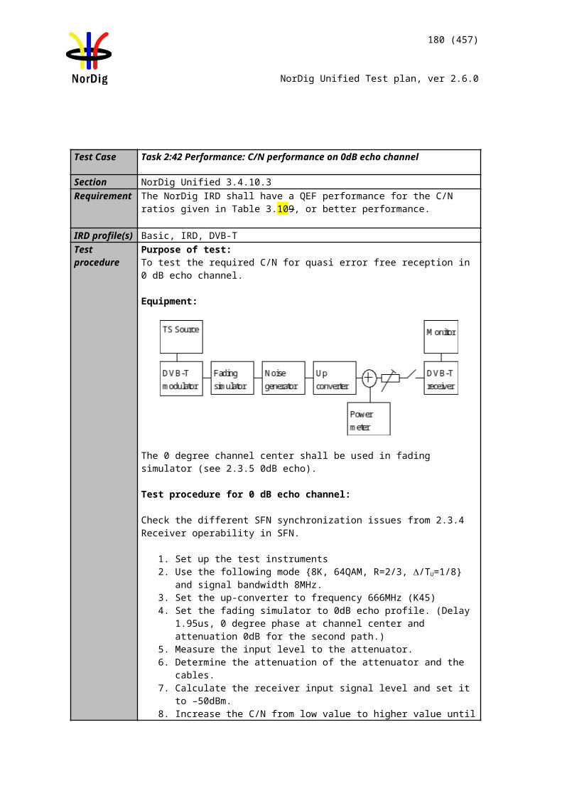
180 (457)
NorDig Unified Test plan, ver 2.6.0
Using DVB-T2 mode specified (Lf=62 symbols) below allows total bit rate of 36.55190642Mbit/s. Using FEF and T2 frame size relation above, the TS bit rate is 35.14229377 Mbit/s.
Test procedure:
1. Set up the test instruments.2. Use the following DVB-T2 mode {32K extended, 256QAM, PP4, R=2/3,
/TU=1/16} and signal bandwidth 8MHz in exciter. 3. Use Gaussian channel without additional noise or interference.4. Set the receiver input level to -50 dBm.5. Verify the received signal carrying services using quality measurement procedure
2 (QMP2).6. Disable FEF from broadcast.7. After possible short interruption on the received service just when FEF is disabled,
the receiver shall recover by itself and continue decoding of the service.8. Verify the received signal carrying services using quality measurement procedure
2 (QMP2). 9. Enable FEF in broadcast.10. After possible short interruption on the received service just when FEF is enabled,
the receiver shall recover by itself and continue decoding of the service.11. Verify the received signal carrying services using quality measurement procedure
2 (QMP2).
Expected result:
Broadcasting of FEF doesn’t cause any harm to receiver and services carried within TS are decoded correctly.
Receiver doesn’t need any actions from end user to maintain reception when FEF is disabled and enabled.
Test result(s)
Conformity OK Fault Major Minor, define fail reason in commentsComments If possible describe if fault can be fixed with software update: YES NO
Describe more specific faults and/or other information
Date Sign
Test Case Task 3:45 DVB-T2: Input Mode A (RBM when FEF present)
Section NorDig Unified 3.4.3Requirement Within the NorDig IRD specification the concept of “DVB-T2 mode” includes e.g. (the list
is not exhaustive): Input Mode A (single PLP) or Input Mode B (Multiple PLPs – Common PLP,
Type 1 and 2 up to the maximum allowed figure 255)
DVB-T2 signal introduces a receiver buffer model (RBM) which is fundamental when it comes to receive signals where carried transport stream doesn’t have constant bit rate as it is case when FEF is present.
IRD Profile(s) Basic, IRD, DVB-T2Test procedure Purpose of test:
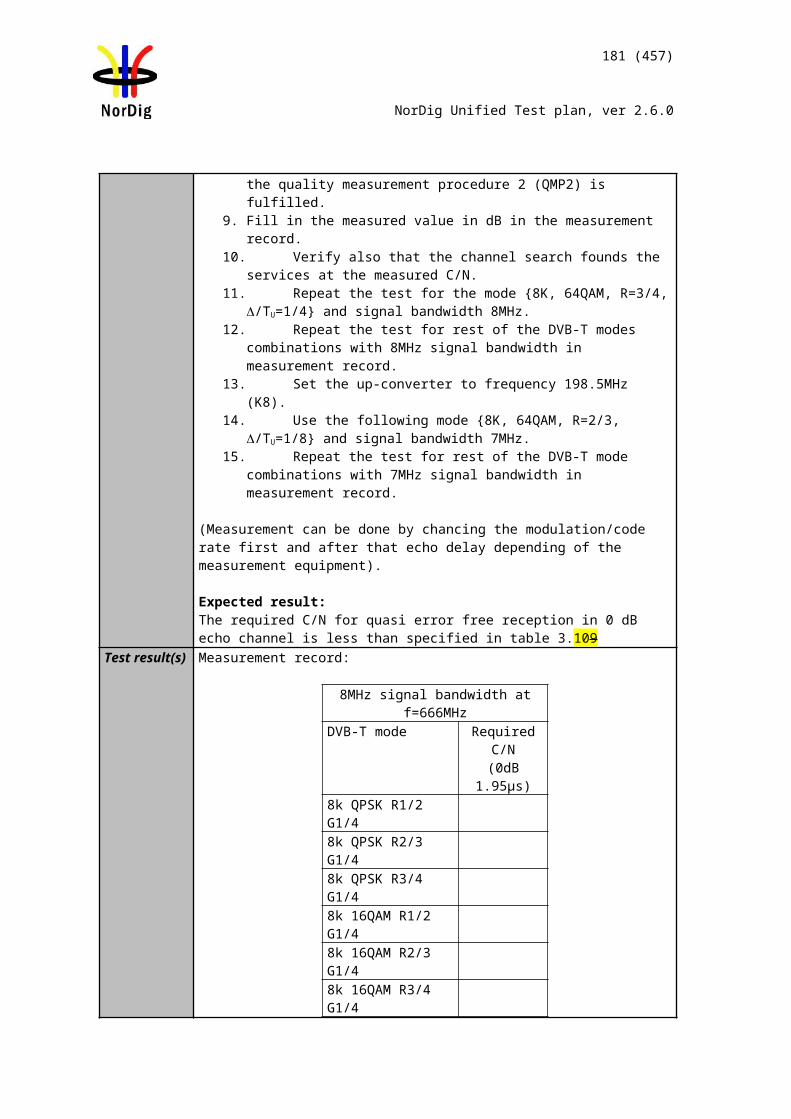
181 (457)
NorDig Unified Test plan, ver 2.6.0
To verify that received DVB-T2 signal can stress the receiver RBM based on DVB V&V tests.
Equipment:
Use Mode A (Single PLP) and following deviations to parameter settings defined in 2.3.7 Summary of DVB-T2 modes for NU_S34:
PLP Code rate 3/5PAPR TR & L1-ACEPAPR Vclip 3.55VL1_ACE_MAX 0.1ISSY EnabledFEF YesAuxiliary streams Not usedFrames per superframe (NT2) 6FEF P1: S1 Value 2FEF P1: S2 Value 1T2 P1:S2 Value 1FEF size 595420 samplesDesign delay 719388 samplesBUFS 2097152
The DVB-T2 signal shall contain a FEF with PRBS content and with a FEF interval of 6 T2 frames.
The size of the PRBS FEF is 595420 samples and T2 frame size Lf=62symbols.
T2 frames shall carry a TS. TS bitrate is restricted to maximum of 4.5MBit/s.
The content of the TS is maximed to TS bit rate.
TS contains at least one service.
The configuration files are available for download on NorDig homepages.
Using DVB-T2 mode specified (Lf=62symbols) below allows total bit rate of 32.849069 Mbit/s. Using FEF and T2 frame size relation above, the TS bit rate is 31.406587 Mbit/s.
Test procedure:
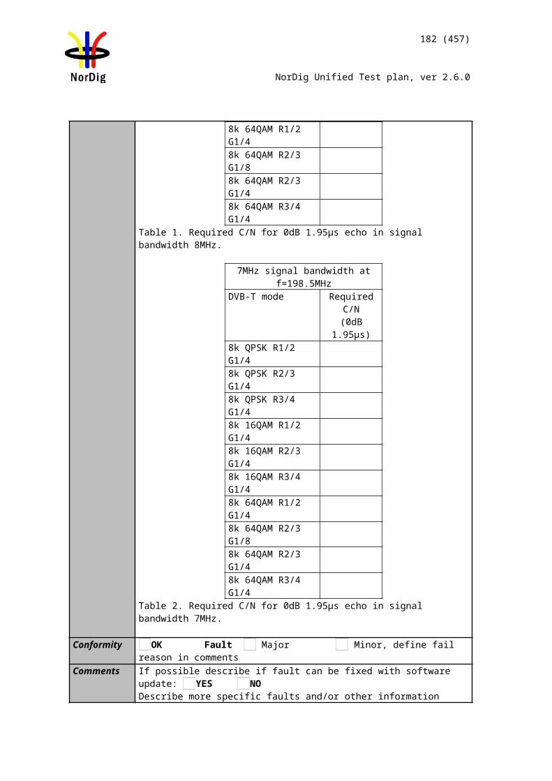
182 (457)
NorDig Unified Test plan, ver 2.6.0
1. Set up the test instruments.2. Use the following DVB-T2 mode {32K extended, 256QAM, PP4, R=3/5,
/TU=1/16} and signal bandwidth 8MHz in exciter according to description above of the DVB-T2 signal.
3. Use Gaussian channel without additional noise or interference.4. Set the receiver input level to -50 dBm.5. Perform channel search and make sure the receiver has deleted any possible old
service on the channel list.6. Verify the received signal carrying services using quality measurement procedure
2 (QMP2).
Expected result:
Broadcasting of DVB-T2 signal according to signal description which stresses the RBM is demodulated correctly and services carried within TS are decoded correctly.
Test result(s)
Conformity OK Fault Major Minor, define fail reason in commentsComments If possible describe if fault can be fixed with software update: YES NO
Describe more specific faults and/or other information
Date Sign
Test Case Task 3:46 DVB-T2: Auxiliary streamsSection NorDig Unified 3.4.3Requirement The NorDig terrestrial IRD is not required to demodulate or decode the content of FEF
parts andauxiliary streams, but the existence of FEFs and/or auxiliary streams shall not cause receiver to malfunction.
IRD Profile(s) Basic, IRD, DVB-T2Test procedure Purpose of test:
To verify that broadcasting of AUX doesn’t cause any harm for the receiver.
Equipment:
Use Mode A (Single PLP) and following deviations to parameter settings defined in 2.3.7Summary of DVB-T2 modes in DVB-T2 test tasks:
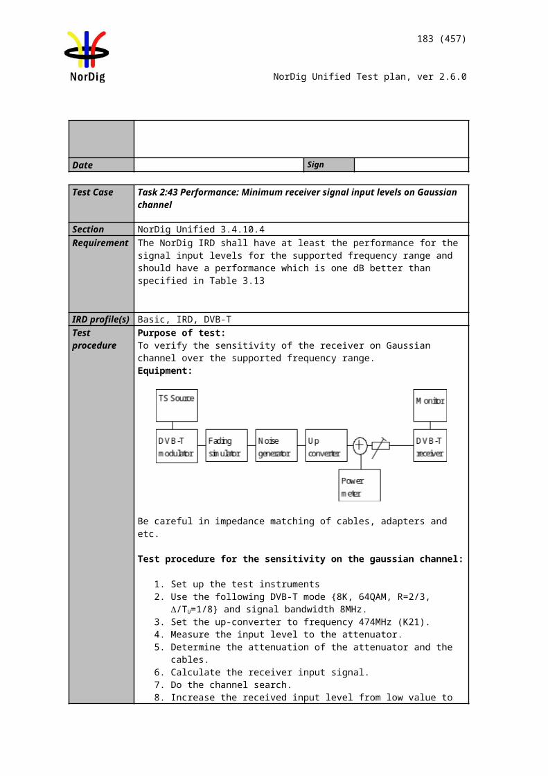
183 (457)
NorDig Unified Test plan, ver 2.6.0
Auxiliary streams Yes
The DVB-T2 signal shall contain auxialiary stream in T2 dummy cells with T2 frame size of Lf=62 symbols. The DVB-T2 signal with specified mode parameters contains 221 dummy cells.
Auxialiary stream content is T2-TX-SIG according to specification ETSI TS 102 992. Tested receiver is not required to interprete content in the T2-TX-SIG. The T2-TX-SIG information is carried within 193 dummy cells out the available 221 dummy cells.
Configuration of T2-TX-SIG signaling is following:M=15 (maximum number of transmitters signaled)N=8 (number of cells per symbols and frame)L= 15 (repetation rate for T2 frames)
T2 frames shall carry a TS. TS bitrate should be maximized to the capacity the T2 frame size can deliver.
The content within TS is maximized to bit rate the TS can carry, with other words, minimize the NULL packets in TS.
TS contains at least one service.
Test procedure:1. Set up the test instruments.2. Use the following DVB-T2 mode {32K extended, 256QAM, PP4,
R=2/3,/TU=1/16} and signal bandwidth 8MHz in exciter. 3. Use Gaussian channel without additional noise or interference.4. Set the receiver input level to -50 dBm.5. Verify the received signal carrying services using quality measurement procedure
2 (QMP2).
Expected result:Broadcasting of auxiliary stream doesn’t cause any harm to receiver and services carried within TS are decoded correctly.
Test result(s)
Conformity OK Fault Major Minor, define fail reason in commentsComments If possible describe if fault can be fixed with software update: YES NO
Describe more specific faults and/or other information
Date Sign
Test Case Task 3:47 DVB-T2: Reception of version 1.1.1 Section Nordig Unified 3.4.3Requirement Receiver shall be able to receive version v1.1.1 of the DVB-T2 system when ISSY is
enabled.
IRD profile(s) Basic, IRD, DVB-T2Test procedure Purpose of test:
To verify receiver is able to receive DVB-T2 version 1.1.1 when ISSY is enabled.
184 (457)
NorDig Unified Test plan, ver 2.6.0
Equipment:
Use Mode A (Single PLP) and following deviations to parameter settings defined in 2.3.7 Summary of DVB-T2 modes in DVB-T2 test tasks:
Version 1.1.1
ISSY Enabled or disabled
The DVB-T2 modulator is configured with parameters 8 MHz signal bandwidth, 32k extended, 256QAM rotated, GI1/16, PP4, R2/3, L1-ACE & TR PAPR, Lf= 62.
Test procedure:1. Tune receiver to signal with configuration according to measurement result.2. Verify the services are decoded correctly.
Expected result:Receiver is able to decode services correctly for DVB-T2 system v1.1.1 when ISSY is enabled or disabled.
Test result(s) Measurement result:
Mode ISSY NOK or OK32k extended, 256QAM rotated, GI1/16, PP4, R2/3, L1-ACE & TR PAPR, Lf= 62
Disabled
32k extended, 256QAM rotated, GI1/16, PP4, R2/3, L1-ACE & TR PAPR, Lf= 62
Enabled
Conformity OK Fault Major Minor, define fail reason in commentsComments If possible describe if fault can be fixed with software update: YES NO
Describe more specific faults and/or other information
Date Sign
Test Case Task 3:48 DVB-T2: Tuning/Scanning Procedures: Automatic channel search for the same service bouquet
Section NorDig Unified 3.4.4.4Requirement The IRD shall provide an automatic search that finds all of the multiplexes and services
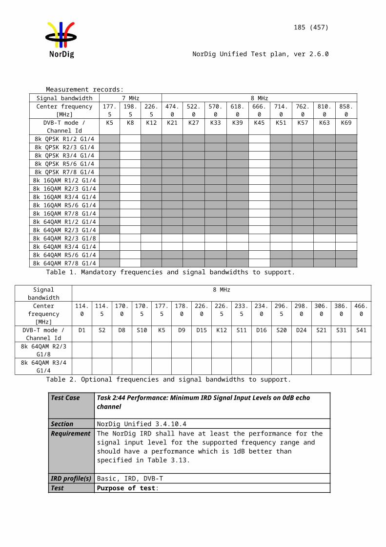
185 (457)
NorDig Unified Test plan, ver 2.6.0
in the whole (supported) frequency range, see NorDig specification. The logic of the automatic search function shall be as follows:
If any services are detected during the automatic search the current service list shall be replaced by the new service list.If no services are detected during the automatic search the current service list shall be kept or deleted.
The IRD shall only display a service once in the service list (i.e. avoiding duplicate of the same services), even if the same service (same triplet original_network_id, transport_stream_id and service_id) is received from multiple transmitters. If the same service can be received from several transmitters, the one with best reception quality shall be selected. The criteria for selection of the best received service (i.e. best reception quality) shall be based on the combination of the signal strength and signal quality according to NorDig specification.
IRD profile(s) Basic, IRD, DVB-T2Test procedure Purpose of test:
To verify the best service selection in automatic channel search when the content of the transport stream is the same on several transmitters.
Equipment:
Channels A and BTS source #1ONID=8945
Network ID=1000Network Name=Net1
TSID=100Services
Name SID Logic Ch NoS1 1 1S2 2 2S3 3 3S4 4 4
There is a possibility to receive broadcasts from several transmitters simultaneously in
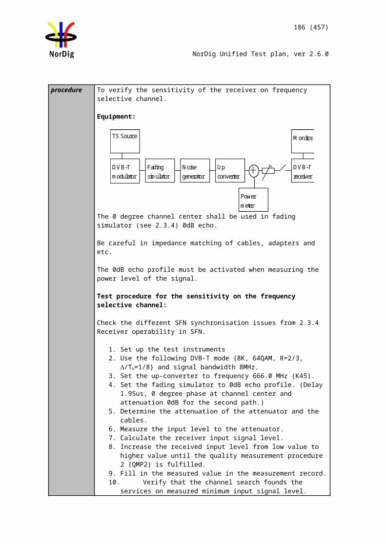
186 (457)
NorDig Unified Test plan, ver 2.6.0
DVB-T2 networks. These transmitters can have exactly the same content, but are transmitted on different channels (frequencies). Therefore, it is important that the receiver can choose by an automatic channel search the services with the best reception quality.
Test to verify broadcast where equal services are broadcasted simultaneously over DVB-T and DVB-T2 networks is not required.
Reception quality can be divided into two different parameters: Signal strength Signal quality
Signal quality can be divided into two main parameters: Signal-to-noise ratio (C/N) Bit error rate before BCH (BER before BCH in DVB-T2 system)
Channels A and B shall not be equal.
Relative signal levels can be observed on spetrum analyser.
∆S refers to difference in SSI according to [1] Annex D.
∆Q refers to difference in SQI according to [1] Annex D.
AWGN refers to Additive White Gaussian Noise.
As a pre-requisite to perform this test, IRD shall correctly pass the following tasks: Task 3:50 Verification of Signal Strength Indicator (SSI) Task 3:51 Verification of Signal Quality Indicator (SQI)
Measurement record2 shows the minimum tests that shall be performed. Signal levels and signal quality (i.e added AWGN) can be adjusted from the initial values shown to ensure the required ∆S and ∆Q conditions are met.
Test procedure:
1. Configure the transport stream and setup the instruments. Use the DVB-T2 mode 32k extended bandwidth, 256QAM rotated, GI1/16, PP4, R2/3, L1-ACE & TR PAPR.
2. Set the signal level of the both carriers CH A and CH B to the same level. The signal level shall correspond good reception quality (no errors in decoded video).
3. Perform automatic channel search. The logic of the automatic search function shall be as follows:
If any services are detected during the automatic search the current service list shall be replaced by the new service list.
If no services are detected during the automatic search the current service list shall be kept or deleted.
4. Check that the channel list has services configured in the transport stream.5. Check that the services on the channel list is listed once and not duplicated.
Check which channel is received by trying to attenuate the signal level. The services from received channel are frozen when the signal level is too low. Restore the attenuations to a level before it was changed.
6. Fill in OK or NOK in the measurement record depending if the services were deleted.
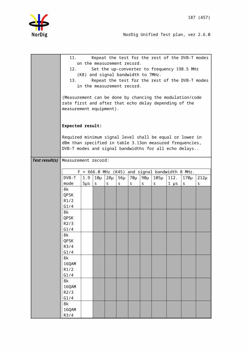
187 (457)
NorDig Unified Test plan, ver 2.6.0
7. Fill in OK or NOK in the measurement record 2 depending if the services were installed from expected channel.
Repeat the test for the rest of the test points in the measurement record 2.
Expected result:All the test results are OK.
Test result(s) Measurement record 1:
Requirement Result OK or NOK
The logic of the automatic search function shall be as follows:
If any services are detected during the automatic search the current service list shall be replaced by the new service list.
If no services are detected during the automatic search the current service list shall be kept or deleted.
After automatic channel search the channel lists do not contain duplicated services.
Measurement record 2 is found on next page.
Conformity OK Fault Major Minor, define fail reason in commentsComments If possible describe if fault can be fixed with software update: YES NO
Describe more specific faults and/or other information
Date Sign
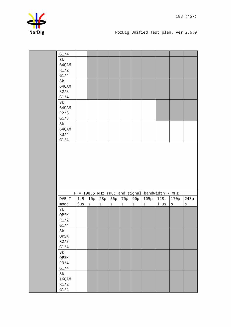
188 (457)
NorDig Unified Test plan, ver 2.6.0
Channel A, f = 474 MHz Channel B, f = 690 MHzTestpoint
Initial signal level
[dBm]
Initial CNR[dB]
Additional BER Impair-
ment
Initial sig-nal level[dBm]
Initial CNR[dB]
Additional BER Impairment
RequiredΔS[%]
RequiredΔQ[%]
Receiverchannelchoice
Expectedchannelchoice
ResultOK/NOK
Reference conditions
in flowchart [1] Annex D
1 -60 no AWGN None -60 no AWGN None <10 <10 A or B 1,2,3,5,6 or 7
2 -50 no AWGN None -65 no AWGN None >10 <20 A 1 or 83 -65 no AWGN None -50 no AWGN None >10 <20 B 4 or 54 -61 CNR@QMP2+1dB None -60 CNR@QMP2+0.5d
BNone <10 <20 A 3
5 -60 CNR@QMP2+0.5dB None -61 CNR@QMP2+1dB None <10 <20 B 76 -61 no AWGN None -60 CNR@QMP2+1dB None <10 >20 A 27 -60 CNR@QMP2+1dB None -61 no AWGN None <10 >20 B 68 -50 no AWGN None -65 CNR@QMP2+1dB None >10 >20 A 19 -65 CNR@QMP2+1dB None -50 no AWGN None >10 >20 B 5
Table 21 Measurement record 2 for test Task 3:48.
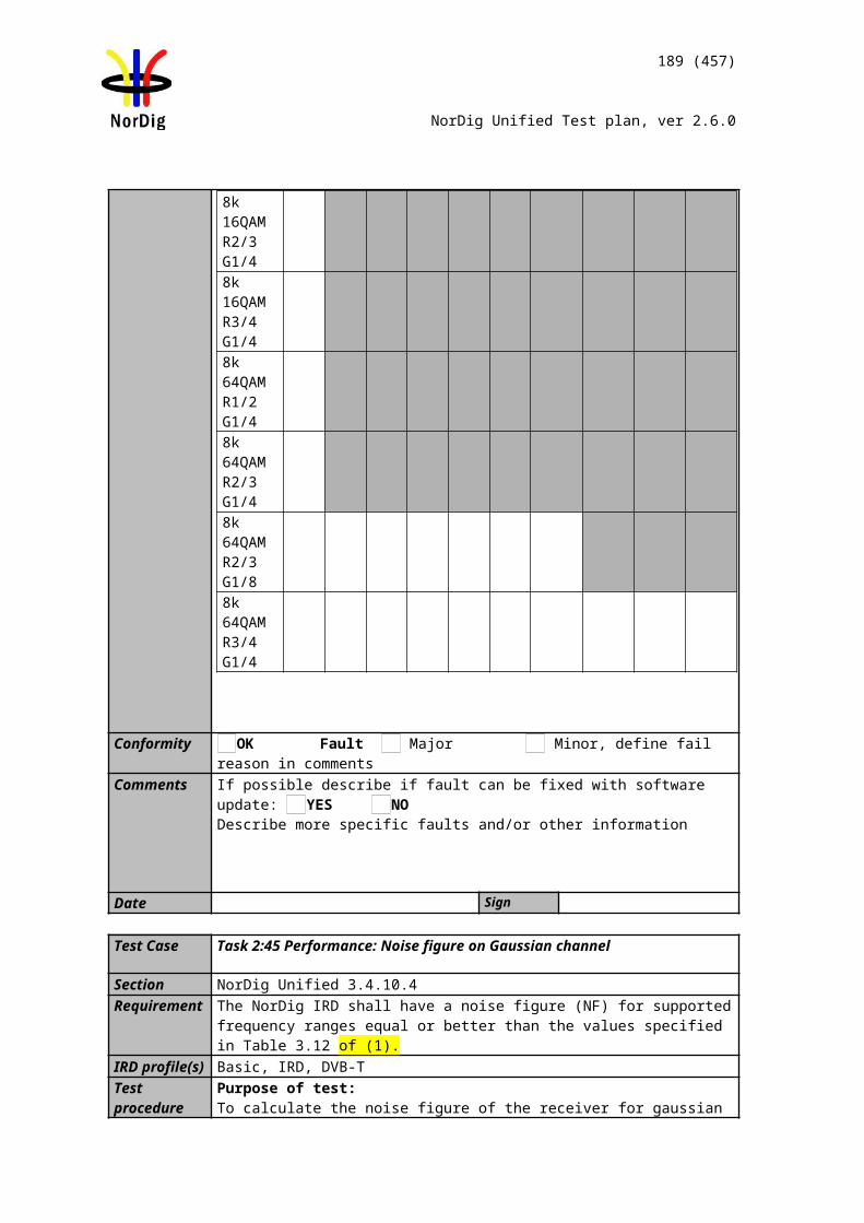
189 (457)
NorDig Unified Test plan, ver 2.6.0
Test Case Task 3:49 DVB-T2: Tuning/Scanning Procedures: Basic status check
Section NorDig Unified 3.4.4.2Requirement The IRD shall provide at least a basic status check function (accessible through the
Navigator) that presents reception quality information for a selected frequency (currently viewed by the user).The basic status check shall include:
channel id center frequency Signal Strength Indicator, SSI (%) Signal Quality Indicator, SQI (%)
IRD Profile(s) Basic, IRD, DVB-T2Test procedure Purpose of test:
To verify that specified status information is displayed correctly.
Equipment:
Test procedure:1. Configure the test setup2. Tune IRD to received frequency3. Verify the basic status check functionality 4. Write in the results in the measurement record
Expected result:All test results in measurement record are OK.
Test result(s) Measurement record
Requirement NOK or OKNavigator has status check function.The function shows the channel id and center frequency. The function shows signal strength indicator SSI in %. The function has reception quality indicator SQI in %.
Conformity OK Fault Major Minor, define fail reason in commentsComments If possible describe if fault can be fixed with software update: YES NO
Describe more specific faults and/or other information
Date Sign
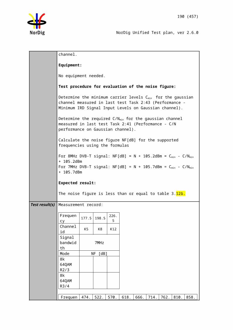
190 (457)
NorDig Unified Test plan, ver 2.6.0
Test Case Task 3:50 DVB-T2: Verification of Signal Strength Indicator (SSI)
Section NorDig Unified 3.4.4.6Requirement The NorDig IRD shall be provided with a signal strength indicator (SSI). The value for
the SSI shall be referred to the IRD RF signal input.
The NorDig IRD shall be able to determine signal strength within a range starting from 15 dB lower than the reference signal level defined in (1) and up to 35dB above that value or maximum signal input level defined in section (1)
The absolute accuracy shall be ±5 dB at RF signal input levels -80 dBm to -60 dBm and ±7 dB for RF signal input levels higher than -60 dBm.
The relative accuracy should be ±3 dB between center frequencies within one frequency band, e.g. VHF Band III or UHF Band IV/V, supported by the receiver.
Signal strength indicator shall have a relative value within a range from 0% to 100% and with a resolution of 1%.
The signal strength indicator shall be updated regularly once per second.
IRD Profile(s) Basic, IRD, DVB-T2Test procedure Purpose of test:
To verify the correct functionality of the signal strength indicator.
Equipment:
Gaussian channel profile used i.e. no need for fading simulator.
In this test, the signal input level Pinput level at the RF input must be known.
The test procedure assumes that the Preceiver is not displayed by the receiver. If the Preceiver
is displayed by the receiver this test procedure can be simplified.
Test procedure:
Verify the SSI value:
1. Set-up the test system2. Determine the attenuation of the test system so that the signal input level
at the receiver input is known in the measured frequencies.3. Use the following DVB-T2 mode {32K extended, 256QAM, PP4,
R=2/3,/TU=1/16} and signal bandwidth of 8MHz. 4. Set the up-converter to frequency 474MHz (K21).5. Set the signal level into the receiver according to measurement record 1.6. Do the channel search.7. Fill in the SSI value displayed by the receiver in the measurement record
1.
Preceiver
DVB-T2receiver
DVB-T2Exciter
TSSource Monitor
Pinput level
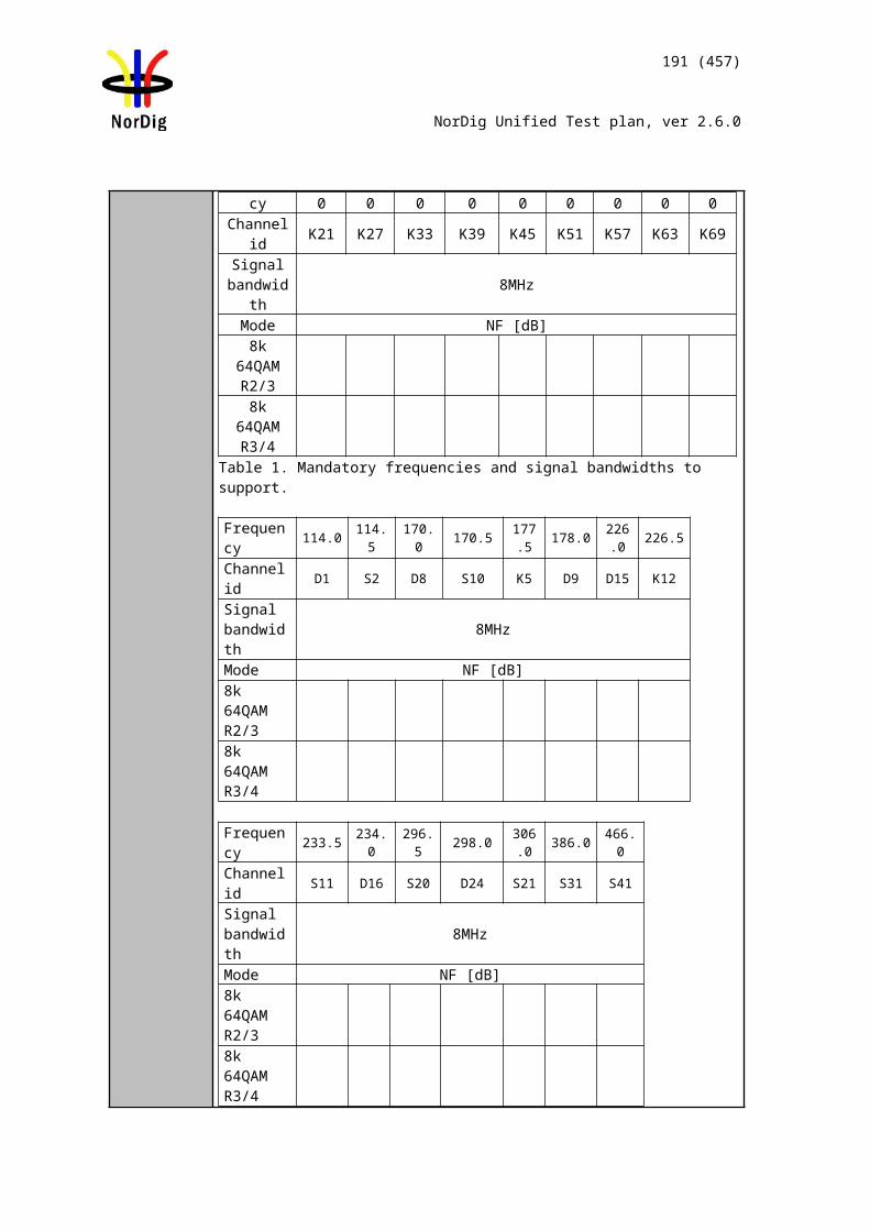
191 (457)
NorDig Unified Test plan, ver 2.6.0
8. SSImin and SSImax defines the allowed range of the displayed value. 9. Fill in the measurement record 1 OK or NOK depending of the displayed
SSI value.10. Measure rest of the frequencies and DVB-T2 modes.11. Fill in the measurement record 1.
Verify the relative error:
1. Convert the displayed SSI values to Preceiver [dBm]. Select the correct formula for calculating Preceiver according to the displayed SSI value as shown below:
Preceiver = (3/2) * (SSI - 90) + 20 + Preference if 90 ≤ SSI < 100Preceiver = (1/4) * (SSI - 10) + Preference if 10 ≤ SSI < 90Preceiver = (3/2) * SSI - 15 + Preference if 0 ≤ SSI < 10
2. Fill in the dBm values in the measurement record 2 for corresponding signal input level.
3. Calculate the average value of the Preceiver values in three frequencies within a frequency band.
4. Verify the calculated Preceiver [dBm] values are within ±3 dB from the average value.
5. Fill in the measurement record 2 OK or NOK.
Expected result: All the measurements shall be OK.
Displayed SSI shall be displayed in [%] and updated once per second.
Test result(s)Measurement record 1:
32KE,256QAMR,PP4,R2/3,G1/16,8MHz,Preference=-78dBm, f=666MHzPinput level [dBm] SSI [%] SSImin [%] SSImax [%] NOK or OK
-40 97 100-50 91 100-60 62 92-70 22 62-80 5 22-95 0 3
32KE,256QAMR,PP4,R2/3,G1/16,8MHz,Preference=-78dBm, f=474MHzPinput level [dBm] SSI [%] SSImin [%] SSImax [%] NOK or OK
-40 97 100-50 91 100-60 62 92-70 22 62-80 5 22-95 0 3
32KE,256QAMR,PP4,R2/3,G1/16,8MHz,Preference=-78dBm, f=786MHzPinput level [dBm] SSI [%] SSImin [%] SSImax [%] NOK or OK
-40 97 100
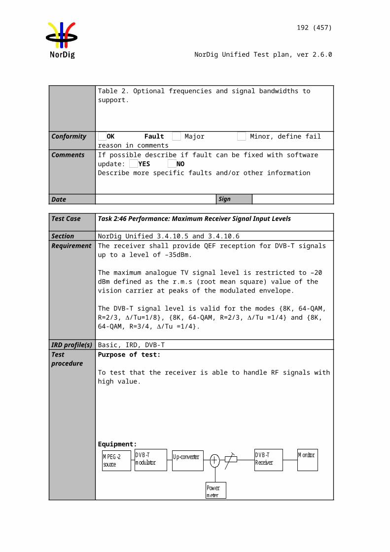
192 (457)
NorDig Unified Test plan, ver 2.6.0
-50 91 100-60 62 92-70 22 62-80 5 22-95 0 3
32KN,256QAMR,PP4,R2/3,G19/256,7MHz,Preference=-78dBm, f=177.5MHzPinput level [dBm] SSI [%] SSImin [%] SSImax [%] NOK or OK
-40 97 100-50 91 100-60 62 92-70 22 62-80 5 22-95 0 3
32KN,256QAMR,PP4,R2/3,G19/256,7MHz,Preference=-78dBm, f=198.5MHzPinput level [dBm] SSI [%] SSImin [%] SSImax [%] NOK or OK
-40 97 100-50 91 100-60 62 92-70 22 62-80 5 22-95 0 3
32KN,256QAMR,PP4,R2/3,G19/256,7MHz,Preference=-78dBm, f=226.5MHzPinput level [dBm] SSI [%] SSImin [%] SSImax [%] NOK or OK
-40 97 100-50 91 100-60 62 92-70 22 62-80 5 22-95 0 3
32KE,256QAMR,PP4,R3/5,G19/256,8MHz,Preference=-80dBm, f=666MHzPinput level [dBm] SSI [%] SSImin [%] SSImax [%] NOK or OK
-40 99 100-50 92 100-60 70 93-70 30 70-80 57 308-95 0 5
32KE,256QAMR,PP2,R3/4,G1/8,8MHz,Preference=-76dBm, f=666MHzPinput level [dBm] SSI [%] SSImin [%] SSImax [%] NOK or OK
-40 96 100-50 86 10099-60 54 9391-70 14 7054-80 34 3814
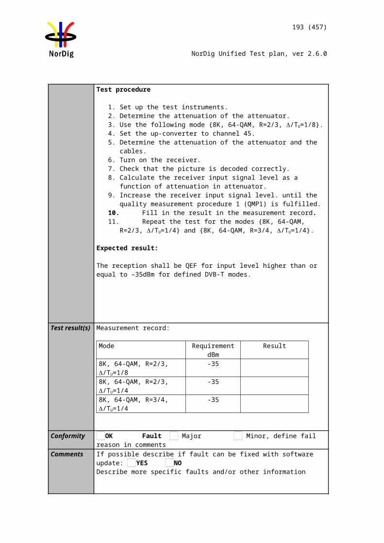
193 (457)
NorDig Unified Test plan, ver 2.6.0
-95 0 52
Measurement record 2:
Pinput level [dBm]
Preceiver [dBm] @474MHz
Preceiver [dBm]@666MHz
Preceiver [dBm] @786MHz
Average NOKor
OK-40-50-60-70-80-95
Pinput level [dBm]
Preceiver
[dBm] @177.5MHz
Preceiver
[dBm] @198.5MHz
Preceiver
[dBm] @226.5MHz
Average NOKor
OK-40-50-60-70-80-95
Conformity OK Fault Major Minor, define fail reason in commentsComments If possible describe if fault can be fixed with software update: YES NO
Describe more specific faults and/or other information
Date Sign
Test Case Task 3:51 DVB-T2: Verification of Signal Quality Indicator (SQI)
Section NorDig Unified 3.4.4.7.2Requirement The NorDig IRD for DVB-T2 shall be provided with a signal quality indicator (SQI).
The value for the SQI shall be referred to a PLP in the received signal at the NorDig IRD RF signal input. The signal quality indicator shall have a relative value within a range from 0% to 100% and with a resolution of 1%.
The integration time for the signal quality shall be over a period of 5 seconds. The signal quality indicator shall be updated regularly at least once per second.
The signal quality indicator (SQI) in [%] shall be calculated for the received PLP according to the formulas defined in [1].
IRD Profile(s) Basic, IRD, DVB-T2Test procedure Purpose of test:
To verify the correct functionality of the signal quality indicator.
Equipment:
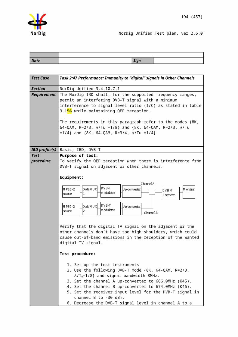
194 (457)
NorDig Unified Test plan, ver 2.6.0
Gaussian channel profile used i.e. no need for fading simulator.
C/Ninput refers to generated DVB-T2 signal C/N at receiver input.
C/Nreceiver refers to C/N determined by the receiver under test.
C/Nrel = C/Ninput – C/NNorDigP1
C/NNorDigP1 refers to table 3.11 at [1].
First we need to define the required C/Ninput for the QMP2. After that we know what is the expected rescale of BER_SQImin and BER_SQImax.
Test procedure:
1. Set up the test instruments2. Use the following DVB-T2 mode {32KE, 256QAMR, PP4, R3/5, G19/256}
and signal bandwidth 8MHz.3. Set the up-converter to frequency 666MHz (K45).4. Do the channel search.5. Determine the lowest required C/N by adjusting the C/Ninput until the quality
measurement procedure 2 error free video is fulfilled.6. Fill in the measurement record 1 the C/Ninput value defined as C/Nreceiver. Later in
this test procedure the value C/Nreceiver is used for rescaling of the BER_SQImin
and BER_SQImax values.7. Decrease the C/Ninput in 1dB step starting from highest value in measurement
record 2.8. Fill in the displayed SQI in the measurement record 2.9. Repeat the test for the DVB-T2 mode {32KE, 256QAMR, PP4, R2/3, G1/16}
and signal bandwidth 8MHz.10. Repeat the test for the DVB-T2 mode {32KE, 256QAMR, PP2, R3/4, G1/8}
and signal bandwidth 8MHz.11. Do the calculations in the rest of the test procedure.
SQImin calculations:
12. Calculate SQImin for all C/Ninput values using formulas SQImin = 0, if C/Nrel -1 < -3 dBSQImin = (C/Nrel -1 + 3)*BER_SQImin, if -3 dB ≤ C/Nrel -1 ≤ 3 dBSQImin = 100, if C/Nrel -1 > 3 dB.
SQImax calculations:
13. Calculate SQImax for all C/Ninput values using formulas SQImax = 0, if C/Nrel +1 < -3 dBSQImax = (C/Nrel +1 + 3)*BER_SQImax, if -3 dB ≤ C/Nrel +1 ≤ 3 dBSQImax = 100, if C/Nrel +1 > 3 dB.
DVB-T2receiver
DVB-T2Exciter
TSSource Monitor
C/NinputC/Nreceiver
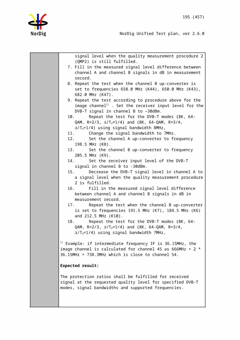
195 (457)
NorDig Unified Test plan, ver 2.6.0
Where BER_SQImin is: BER_SQImin = 0, if C/Nrel -1 –(C/Nreceiver – X) < -2.4 dBBER_SQImin = 100/15, if -2.4 dB ≤ C/Nrel -1 – (C/Nreceiver – X) ≤ -2 dBBER_SQImin = 100/6, if C/Nrel -1 – (C/Nreceiver – X) > -2 dB.
Where BER_SQImax is: BER_SQImax = 0, if C/Nrel +1 - (C/Nreceiver – X) < -2.4 dB BER_SQImax = 100/15, if -2.4 dB ≤ C/Nrel +1 - (C/Nreceiver – X) ≤ -2 dB BER_SQImax = 100/6, if C/Nrel +1 - (C/Nreceiver – X) > -2 dB.
And where X is:X = 17.6 for 32KE, 256QAMR, PP4, R3/5, G19/256, 8MHzX = 19.0 for 32KE, 256QAMR, PP4, R2/3, G1/16, 8MHzX = 20.8 for 32KE, 256QAMR, PP2, R3/4, G1/8, 8MHz
Expected result:
All the test result are OK.The signal quality indicator is updated regurlarly once per second.
Test result(s) Measurement record 1:
DVB-T2 mode Required C/Nreceiver [dB](30 sec error free video)
32KE 256QAMR PP4 R3/5 G19/256 8MHz32KE 256QAMR PP4 R2/3 G1/16 8MHz32KE 256QAMR PP2 R3/4 G1/8 8MHz
Measurement record 2:
32KE 256QAMR PP4 R3/5 G19/256 8MHz, C/NNorDigP1 = 19.4dB
C/Ninput SQI[%] SQImin[%] SQImax[%] NOK or OK2726252423222120191817
32KE 256QAMR PP4 R2/3 G1/16 8MHz, C/NNorDigP1 = 20.8dB
C/Ninput SQI[%] SQImin[%] SQImax[%] NOK or OK27
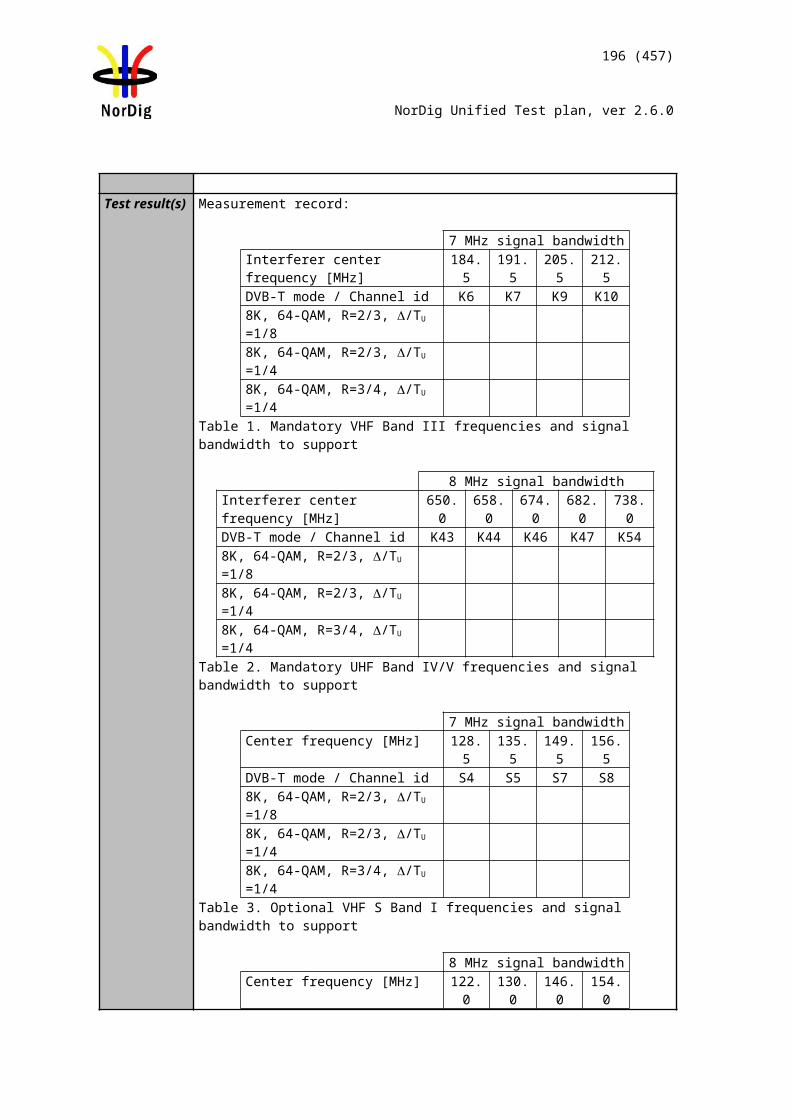
196 (457)
NorDig Unified Test plan, ver 2.6.0
26252423222120191817
32KE 256QAMR PP2 R3/4 G1/8 8MHz, C/NNorDigP1 = 22.9dB
C/Ninput SQI[%] SQImin[%] SQImax[%] NOK or OK2726252423222120191817
Example for calculating SQImin and SQImax values for 256QAMR R3/5 when C/Nreceiver = 17.7dB at QMP2 resulting to C/Nreceiver – X = 0.1dB where X = 17.6:
CNRreceiver @QMP2= 17,7(C/Nreceiver-17.6) @QMP2= 0,1256QAM R3/5 C/NNorDigP1= 19,4
C/ Ninput C/Nrel C/N error
MinC/Nrel errorMin
BER_ SQI Min
C/N errorMax
C/Nrel errorMax
BER_ SQI Max
SQIMin
SQIMax
SQImeasured 256QAM
R3/ 5OK or NOK
15 -4,4 -1 -5,4 0,0 1 -3,4 0,0 0 016 -3,4 -1 -4,4 0,0 1 -2,4 0,0 0 017 -2,4 -1 -3,4 0,0 1 -1,4 16,7 0 27
17,6 -1,8 -1 -2,8 0,0 1 -0,8 16,7 0 3718 -1,4 -1 -2,4 0,0 1 -0,4 16,7 0 4419 -0,4 -1 -1,4 16,7 1 0,6 16,7 26 6020 0,6 -1 -0,4 16,7 1 1,6 16,7 43 7721 1,6 -1 0,6 16,7 1 2,6 16,7 60 9422 2,6 -1 1,6 16,7 1 3,6 16,7 76 10023 3,6 -1 2,6 16,7 1 4,6 16,7 93 10024 4,6 -1 3,6 16,7 1 5,6 16,7 100 10025 5,6 -1 4,6 16,7 1 6,6 16,7 100 10026 6,6 -1 5,6 16,7 1 7,6 16,7 100 10027 7,6 -1 6,6 16,7 1 8,6 16,7 100 100
Conformity OK Fault Major Minor, define fail reason in commentsComments If possible describe if fault can be fixed with software update: YES NO
Describe more specific faults and/or other information
Date Sign
Test Case Task 3:52 DVB-T2: Changes In Modulation Parameters
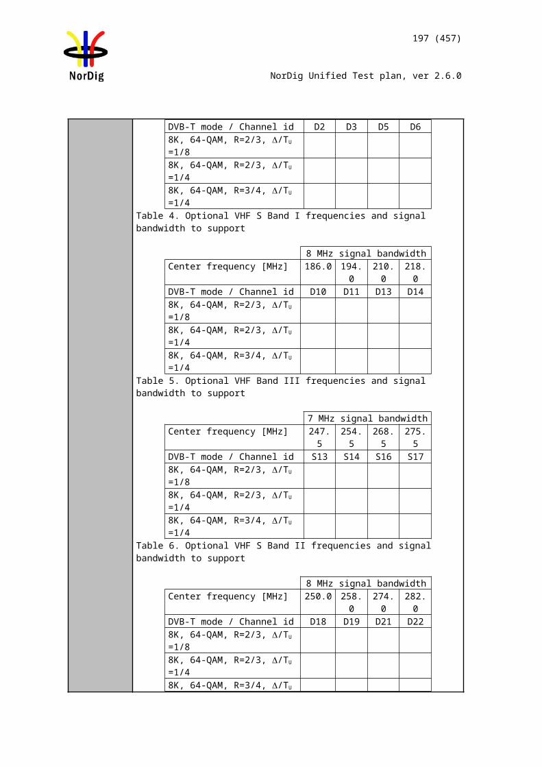
197 (457)
NorDig Unified Test plan, ver 2.6.0
Section NorDig Unified 3.4.5Requirement The terrestrial NorDig IRD-T2 shall automatically recover from changes in the follow-
ing P1, L1 pre-signalling data and L1 post-signalling parameters at the end of a super-frame without a break in the received DVB-T2 signal. An error-free TS shall be avail-able within five seconds for any P1 and/or L1 pre-signalling change. An error-free TS shall be output within five seconds for any L1 post-signalling FEF change andwithin two seconds for any other L1 post-signalling change.
The terrestrial NorDig IRD-T2 shall automatically recover from changes in the following P1, L1 pre-signalling and L1 post-signalling parameters occurring at any time followed by a break in the received signal. An error-free TS shall be output within five seconds.
IRD Profile(s) Basic, IRD, DVB-T2Test procedure Purpose of test:
To verify that receiver can automatically recover from changes in the specified P1, L1 pre-signaling and L1 post-signaling parameter occurring at any time followed by a break in the received signal and output an error free TS.
Equipment:
This test includes the use of L1 post-signalling configurable signaling fields. Those fields signalize transmission parameters per PLP.
Use Mode A (Single PLP) parameter settings defined in 2.3.7 Summary of DVB-T2 modes in DVB-T2 test tasks.
This test checks receiver capability to adapt to parameter changes in broadcasted DVB-T2 signal with break in the received RF signal. The receiver shall adapt to the received signal without any user action.
Different DVB-T2 modulators from different vendors may have different time to broadcast valid signal after the change of the parameter in the broadcasted signal. This time from parameter change to valid signal is excluded from the required receiver synchronization time. Therefore, the test operator needs to know this time and take it to account when calculating the receiver synchronization time.
Synchronisation time is not tested for rotated constellation changes, but receiver operability is tested on test Task 3:36.
Synchronisation time is not tested for time interleaving length changes, but receiver operability is tested on test Task 3:53.
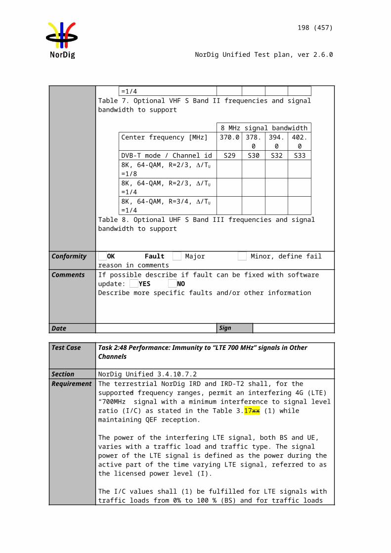
198 (457)
NorDig Unified Test plan, ver 2.6.0
Test procedure:
1. Setup the instruments2. Use frequency 666MHz (K45)3. Use the following DVB-T2 mode
32k extended, 256QAM rotated, G1/16, R2/3 and signal bandwidth 8MHz.4. Open the switch to break the received RF signal5. Change the following transmission parameters in turn by changing the P1, L1
pre-signaling and L1 post signalling respectivelyFFT size: 32K,16K,8K,4K,2K and 1KBandwidth extension: yes, noPAPR: no, ACE, TRGuard interval: G1/32, G1/16, G1/8, G1/4, G1/128, G19/128,G19/256Pilot Pattern: PP2, PP4,PP6,PP7Number of data symbols: 60, 62Code Rate: R3/5, R2/3, R3/4Modulation: 256 QAMT2 system id change from 0 to 65535 (decimal)Cell id change from 0 to 65535 (decimal)Network id change (optional) from 0 to 65535 (decimal)T2 version change from 1.2.1 to 1.3.1PLP_id change from 1 to 2 for TS carrying installed service(s) on the receiver Change of FEF being disabled to enabledChanging length of the FEF, when enabled, from 0 ms to 56.875 ms (other parameters needed to be changed are specified on test Task 3:44)
6. Wait for the DVB-T2 modulator output to become valid and stable (this time is modulator specific – a minimum of 15 seconds is recommended for some modulators)
7. Close the switch to enable the RF signal to the receiver and record the time taken to achieve QMP1.
8. Verify receiver automatically adapts to new parameter settings without any user action.
Expected result:
The receiver can automatically recover from changes in the specified P1, L1 pre-signaling and L1 post-signaling parameter occurring at any time followed by a break in the received signal and output an error free TS within 5 seconds (excluding modulator stabilization time) without requiring a channel scan.
The time limits in this clause exclude the time for the DVB-T2 modulator to output a stable and valid signal.
Test result(s)
Conformity OK Fault Major Minor, define fail reason in commentsComments If possible describe if fault can be fixed with software update: YES NO
Describe more specific faults and/or other information
Date Sign
Test Case Task 3:53 DVB-T2: Time interleaving
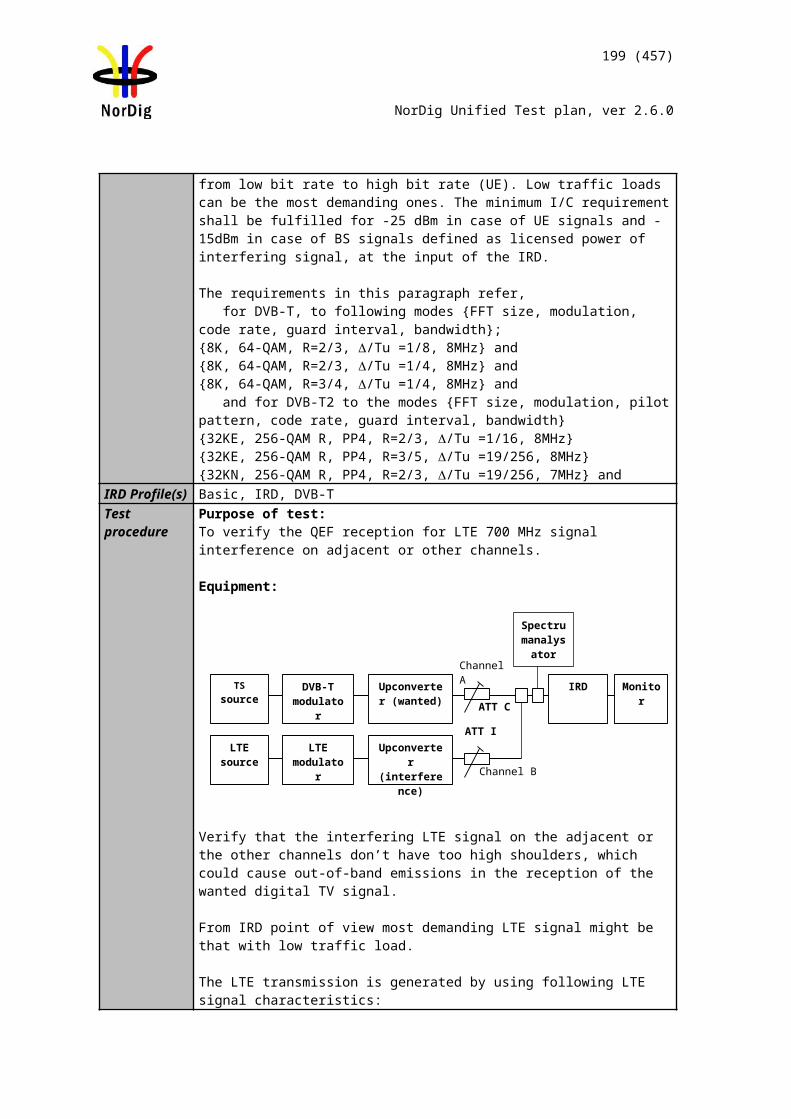
199 (457)
NorDig Unified Test plan, ver 2.6.0
Section NorDig Unified 3.4.8Requirement The NorDig IRD-T2 shall at least include time interleaving capability corresponding to
the maximum time interleaving according to EN 302 755, i.e. 219+215 OFDM cells for a data PLP and its common PLP together.
IRD Profile(s) Basic, IRD, DVB-T2Test procedure Purpose of test:
To verify receiver time interleaving capability.
Equipment:
Use Mode A (Single PLP) parameter settings defined in 2.3.7Summary of DVB-T2 modes in DVB-T2 test tasks.
Test procedure:
1. Set up the test system2. Use DVB-T2 mode 32K extended, 256QAM rotated, PP7, R3/4, G1/128,
8MHz signal bandwidth on 666MHz3. Configure the interleaving type and length according to measurement record in
test results.
Expected result:
The IRD able to decode services carried within TS correctly.
Test result(s) Measurement record:
Interleavingtype
Interleavinglength
Number of blocks
Lf BUFS Design Delay
OK or NOK
0 3 200 60 1613824 6695530 1 68 22 1613824 7370401 2 68 12 1613824 805229
Conformity OK Fault Major Minor, define fail reason in commentsComments If possible describe if fault can be fixed with software update: YES NO
Describe more specific faults and/or other information
Date Sign
Test Case Task 3:54 DVB-T2: Input/Output Data Formats
200 (457)
NorDig Unified Test plan, ver 2.6.0
Section NorDig Unified 3.4.9Requirement The NorDig IRD-T2 shall be able to support TS bit rates ≤ 72 Mbit/s. IRD Profile(s) Basic, IRD, DVB-T2Test procedure Purpose of test:
To verify maximum bit rate from DVB-T2 front end.
Equipment:
Carrier mode ExtendedPAPR OffSISO/MISO SISOFEC Frame length 64800
Input mode Mode ATFS No
Mode HEM
(high efficiency mode)
FEF Not usedAuxiliary streams Not used
Test procedure:
1. Set up the test system2. Use DVB-T2 mode 32K extended, 256QAM rotated, PP7, R5/6, G1/128,
8MHz signal bandwidth on 666MHz3. Configure the interleaving type and length according to measurement record in
test results.
Expected result:
DVB-T2 front end is able to deliver transport streams up to bit rate supported by the DVB-T2 mode (approx 50Mbit/s).
Test result(s)Conformity OK Fault Major Minor, define fail reason in commentsComments If possible describe if fault can be fixed with software update: YES NO
Describe more specific faults and/or other information
Date Sign
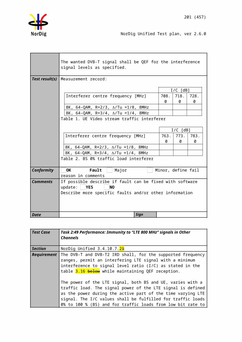
201 (457)
NorDig Unified Test plan, ver 2.6.0
Test Case Task 3:55 DVB-T2: Performance: BER vs C/N verification
Section NorDig Unified 3.4.10.2Requirement Verify the internal BER measurement of the NorDig IRD for objective measurements
(QMP3).IRD Profile(s) Basic, IRD, DVB-T2Test procedure Purpose of test:
To check that the internal BER value measured by the receiver displays correct values.
Equipment:
Test procedure:
1. Setup the instruments.2. Use channel 45 and use Gaussian channel3. Use DVB-T2 mode 32k extended, 256QAM rotated, R2/3, G1/16, PP4, L1-
ACE & TR PAPR and signal bandwidth 8MHz. 4. Set the RF input level to –50dBm.5. Starting from high C/N, decrease the C/N and fill in the corresponding BER
after LDPC value measured by the receiver in measurement record.6. Adjust the C/N to a value which corresponds required C/N for QMP2 “30s
subjective error free video”.7. Decrease C/N by 0.3dB 8. Fill in the BER after LDPC in the measurement record.
Expected result:
The decrease of the required C/N for QMP2 “30s subjective error free video” or BER 1E-7 after LDPC by 0.3dB shall result approximately BER 1E-4 after LDPC.
Test result(s) Measurement record:
C/N Measured BER by the receiver
18.618.819.019.219.419.619.820.020.2
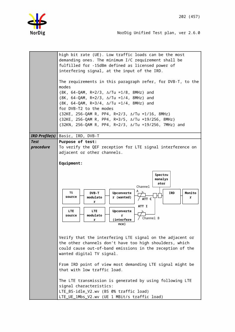
202 (457)
NorDig Unified Test plan, ver 2.6.0
BER after LDPC
C/N@QMP2 „30s error free video“
C/N@QMP2 „30s error free video“ – 0.3dB
Conformity OK Fault Major Minor, define fail reason in commentsComments If possible describe if fault can be fixed with software update: YES NO
Describe more specific faults and/or other information
Date Sign
Test Case Task 3:56 DVB-T2: Performance: C/N performance on Gaussian channel
Section NorDig Unified 3.4.10.3Requirement The NorDig IRD shall have at least the QEF performance for the C/N ratios given in,
Table 2.43 (PP2) and Table 2.76 (PP7) Maximum required C/N for profiles 1 and 2.IRD Profile(s) Basic, IRD, DVB-T2Test procedure Purpose of test:
To test the required C/N for quasi error free reception in Gaussian channel.
Equipment:
Use Mode A (Single PLP) and following deviations to parameter settings defined in 2.3.7Summary of DVB-T2 modes in DVB-T2 test tasks:
Pilot pattern PP7 (7MHz and 8MHz BW)PP2 (1.7MHz BW)
L1 post constellationL1 post constellation must be
more robust than data PLP constellation.
Test procedure for Gaussian channel:
1. Set up the test instruments2. Use the following DVB-T2 mode {32k extended, 256QAM rotated, R2/3,
GI1/128}
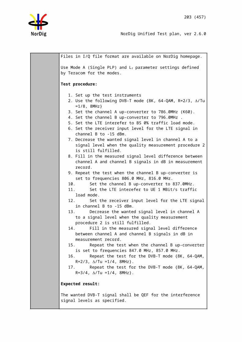
203 (457)
NorDig Unified Test plan, ver 2.6.0
3. Set the up-converter to channel 214. Measure the input level to the attenuator. 5. Determine the attenuation of the attenuator and the cables.6. Calculate the receiver input signal level and set it to –50dBm. 7. Use the value for the required C/N specified for the DVB-T2 mode in Table
2.73.8. Do the channel search.9. Increase the C/N from low value to higher value until the quality measurement
procedure 2 (QMP2) fulfils.10. Fill in the measured value in dB in the measurement record. 11. Repeat the test for the rest of the frequencies, signal bandwidths and DVB-T2
modes defined in the measurement record.
Expected result:
The required C/N for quasi error free reception in Gaussian channel is less than specified in Table 2.76.If 1.7MHz signal BW is supported, the required C/N for quasi error free reception in Gaussian channel is less than specified in Table 2.43.
Test result(s) Measurement record: See tables below.
Conformity OK Fault Major Minor, define fail reason in commentsComments If possible describe if fault can be fixed with software update: YES NO
Describe more specific faults and/or other information
Date Sign
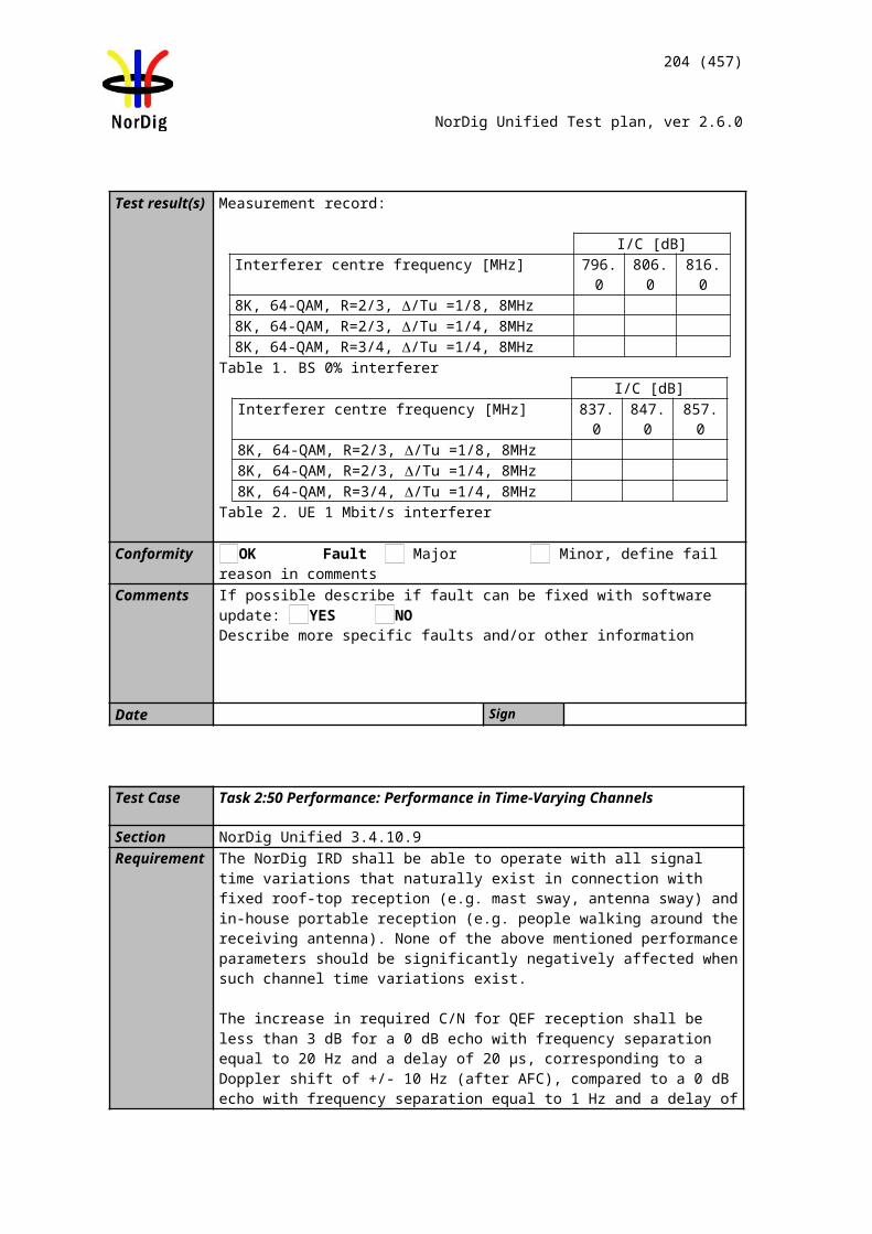
204 (457)
NorDig Unified Test plan, ver 2.6.0
Measurement record:FFT
Signal bandwidth32k normal
7 MHz32k extended
8 MHzCenter frequency [MHz] 177.5 198.5 226.5 474.0 522.0 570.0 618.0 666.0 714.0 762.0 810.0 858.0
DVB-T2 mode / Channel Id K5 K8 K12 K21 K27 K33 K39 K45 K51 K57 K63 K69QPSK R1/2 G1/128QPSK R3/5 G1/128QPSK R2/3 G1/128QPSK R3/4 G1/128QPSK R4/5 G1/128QPSK R5/6 G1/128
16QAM R1/2 G1/12816QAM R3/5 G1/12816QAM R2/3 G1/12816QAM R3/4 G1/12816QAM R4/5 G1/12816QAM R5/6 G1/12864QAM R1/2 G1/12864QAM R3/5 G1/12864QAM R2/3 G1/12864QAM R3/4 G1/12864QAM R4/5 G1/12864QAM R5/6 G1/128256QAM R1/2 G1/128256QAM R3/5 G1/128256QAM R2/3 G1/128256QAM R3/4 G1/128256QAM R4/5 G1/128256QAM R5/6 G1/128
Table 1. Mandatory frequencies and signal bandwidths to support.
FFTSignal bandwidth
8k normal1.7 MHz
32k normal8 MHz
Center frequency [MHz] 206.352 114.0 114.5 170.0 170.5 177.5 178.0 226.0 226.5 233.5 234.0 296.5 298.0 306.0 386.0 466.0DVB-T2 mode / Channel Id 9C D1 S2 D8 S10 K5 D9 D15 K12 S11 D16 S20 D24 S21 S31 S41
256QAM R2/3 G1/8
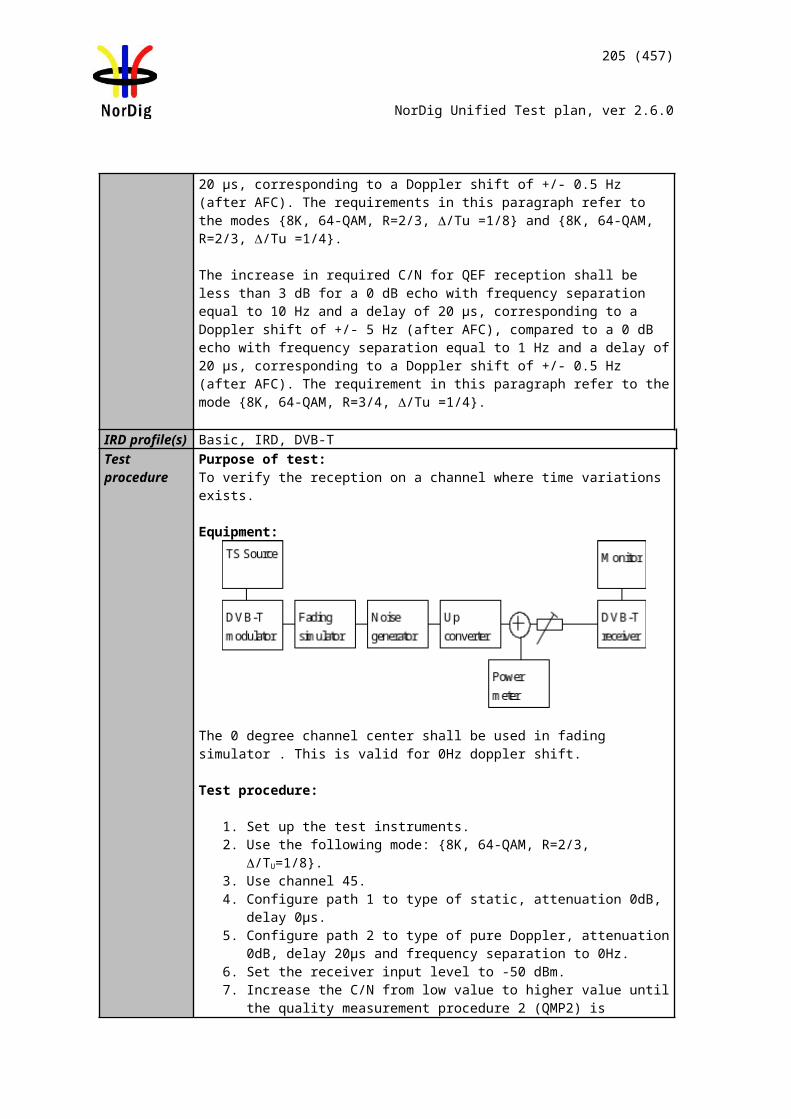
205 (457)
NorDig Unified Test plan, ver 2.6.0
256QAM R2/3 G1/128Table 2. Optional frequencies and signal bandwidths to support.
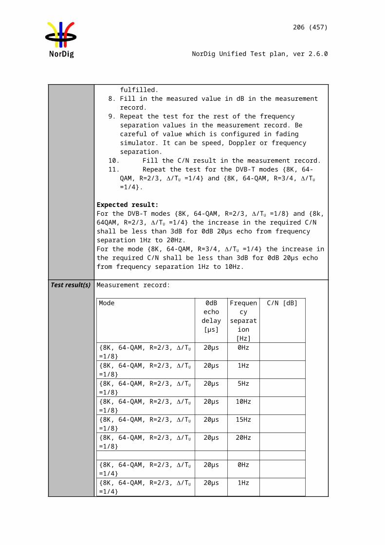
206 (457)
NorDig Unified Test plan, ver 2.6.0
Test Case Task 3:57 DVB-T2: Performance: C/N performance on 0dB echo channel
Section NorDig Unified 3.4.10.3Requirement The NorDig IRD shall have at least the QEF performance for the C/N ratios given in,
Table 2.43 (PP2) and Table 2.54 (PP4) Maximum required C/N for profiles 1 and 2.
IRD Profile(s) Basic, IRD, DVB-T2Test procedure Purpose of test:
To test the required C/N for quasi error free reception in 0 dB echo channel.
Equipment:
The 0 degree channel center shall be used in fading simulator (see 2.3.50dB echo).
Use Mode A (Single PLP) parameter settings defined in 2.3.7Summary of DVB-T2 modes in DVB-T2 test tasks.
Test procedure for 0 dB echo channel:
Check the different SFN synchronization issues from 2.3.4 Receiver operability in SFN.
1. Set up the test instruments2. Use the following DVB-T2 mode {32K extended, 256QAM, PP7, R2/3,
G1/128} and signal bandwidth 8MHz.3. Set the up-converter to frequency 666MHz (K45)4. Set the fading simulator to 0dB echo profile. (Delay 1.95us, 0 degree phase at
channel center and attenuation 0dB for the second path.)5. Measure the input level to the attenuator. 6. Determine the attenuation of the attenuator and the cables.7. Calculate the receiver input signal level and set it to –50dBm. 8. Increase the C/N from low value to higher value until the quality measurement
procedure 2 (QMP2) is fulfilled.9. Fill in the measured C/N value in dB in the measurement record. 10. Verify also that the channel search founds the services at the measured C/N.11. Repeat the test for rest of the DVB-T2 modes combinations with 8MHz signal
bandwidth in measurement record.12. Set the up-converter to frequency 198.5MHz (K8) and verify the input level
into the receiver is -50dBm.13. Repeat the test for rest of the DVB-T2 mode combinations with 7MHz signal
bandwidth in measurement record.
Expected result:
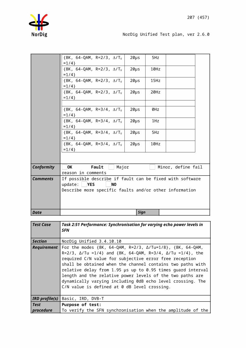
207 (457)
NorDig Unified Test plan, ver 2.6.0
The required C/N for quasi error free reception in 0 dB echo channel is less than specified in Table 2.43 and Table 2.54 except for DVB-T2 mode 32KE 256QAMR R3/4 G1/32 8MHz PP6.If 1.7MHz signal BW is supported, the required C/N for quasi error free reception in Gaussian channel is less than specified in Table 2.43.
Test result(s) Measurement record:
C/N [dB]DVB-T2 mode PP2 PP4 PP6 PP732KE 256QAMR R3/4 G1/8 8MHz N/A N/A N/A32KN 256QAMR R3/4 G1/8 7MHz N/A N/A N/A32KE 256QAMR R3/4 G1/16 8MHz N/A N/A32KN 256QAMR R3/4 G1/16 7MHz N/A N/A32KE 256QAMR R3/4 G1/32 8MHz 1) N/A N/A32KE 256QAMR R3/4 G1/128 8MHz N/A N/A N/A32KN 256QAMR R3/4 G1/128 7MHz N/A N/A N/A
Table 1. Mandatory test for required C/N for 0dB 1.95µs echo.
1) This mode is not required in NorDig performance requirements, but added here in order to compare between different pilot patterns.
Conformity OK Fault Major Minor, define fail reason in commentsComments If possible describe if fault can be fixed with software update: YES NO
Describe more specific faults and/or other information
Date Sign
Test Case Task 3:58 DVB-T2: Performance: Minimum receiver signal input levels on Gaussian channel
Section NorDig Unified 3.4.10.4Requirement The NorDig IRD shall provide QEF reception for the minimum signal levels (Pmin) for
the supported frequency range as stated below (at 290K).
For 7 MHz Normal Bandwidth DVB-T/T2 signal: Pmin = -105.7 dBm+NF [dB]+ C/N [dB], andFor 8 MHz Normal Bandwidth DVB-T/T2 signal: Pmin = -105.2 dBm+NF [dB]+ C/N [dB], andFor 1.7 MHz Normal Bandwidth DVB-T2 signal: Pmin = -112.1 dBm+NF [dB]+ C/N [dB], andFor 7 MHz Extended Bandwidth DVB-T2 signal: Pmin = -105.7 dBm+NF [dB]+ C/N [dB], andFor 8 MHz Extended Bandwidth DVB-T2 signal: Pmin = -105.1 dBm+NF [dB]+ C/N [dB], andFor 1.7 MHz Extended Bandwidth DVB-T2 signal: Pmin = -112.1 dBm+NF [dB]+ C/N [dB],
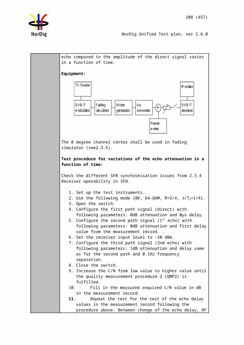
208 (457)
NorDig Unified Test plan, ver 2.6.0
C/N is specified in tables 32.47 and 32.78 (1) and NF is specified in table 3.12 s 3.9 and 3.10 (1).
IRD Profile(s) Basic, IRD, DVB-T2Test procedure Purpose of test:
To verify the sensitivity of the receiver on Gaussian channel over the supported frequency range. Equipment:
Be careful in impedance matching of cables, adapters and etc.
Use Mode A (Single PLP) and following deviations to parameter settings defined in 2.3.7Summary of DVB-T2 modes in DVB-T2 test tasks.
Pilot pattern PP7 (7MHz and 8MHz BW)PP2 (1.7MHz BW)
L1 post constellation L1 post constellation must be more robust than data PLP constellation.
Test procedure for the sensitivity on the gaussian channel:
1. Set up the test instruments2. Use the following DVB-T2 mode {32K extended, 256QAM, R2/3, GI1/128}
and signal bandwidth 8MHz .3. Set the up-converter to frequency 474MHz (K21).4. Measure the input level to the attenuator. 5. Determine the attenuation of the attenuator and the cables.6. Calculate the receiver input signal.7. Do the channel search.8. Increase the received input level from low value to higher value until the
quality measurement procedure 2 (QMP2) is fulfilled.9. Fill in the measured value in the measurement record. 10. Repeat the test for the rest of the frequencies, DVB-T2 modes and signal
bandwidths on measurement record.
Expected result:Sensitivity shall be equal or better for all measured frequencies (channels) and for all DVB-T2 modes and signal bandwidths as specified in Table 2.110. If signal bandwidth 1.7MHz is supported, the sensitivity shall be equal or better for measured frequency and for DVB-T2 mode as specified in Table 2.87.
Test result(s) Measurement record: See following page.
209 (457)
NorDig Unified Test plan, ver 2.6.0
Conformity OK Fault Major Minor, define fail reason in commentsComments If possible describe if fault can be fixed with software update: YES NO
Describe more specific faults and/or other information
Date Sign
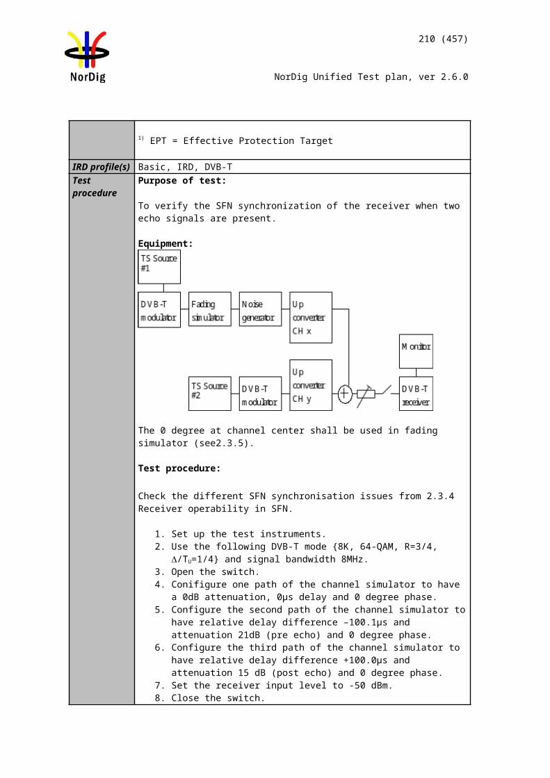
210 (457)
NorDig Unified Test plan, ver 2.6.0
Measurement record:FFT
Signal bandwidth32k normal
7 MHz32k extended
8 MHzCenter frequency [MHz] 177.5 198.5 226.5 474.0 522.0 570.0 618.0 666.0 714.0 762.0 810.0 858.0
DVB-T2 mode / Channel Id K5 K8 K12 K21 K27 K33 K39 K45 K51 K57 K63 K69 QPSK R1/2 G1/128 QPSK R3/5 G1/128 QPSK R2/3 G1/128 QPSK R3/4 G1/128 QPSK R4/5 G1/128 QPSK R5/6 G1/128
16QAM R1/2 G1/128 16QAM R3/5 G1/128 16QAM R2/3 G1/128 16QAM R3/4 G1/128 16QAM R4/5 G1/128 16QAM R5/6 G1/128 64QAM R1/2 G1/128 64QAM R3/5 G1/128 64QAM R2/3 G1/128 64QAM R3/4 G1/128 64QAM R4/5 G1/128 64QAM R5/6 G1/128
256QAM R1/2 G1/128 256QAM R3/5 G1/128 256QAM R2/3 G1/128 256QAM R3/4 G1/128 256QAM R4/5 G1/128 256QAM R5/6 G1/128
Table 1. Mandatory frequencies and signal bandwidths to support.
FFTSignal bandwidth
8k normal1.7 MHz
32k normal8 MHz
Center frequency [MHz] 206.352 114.0 114.5 170.0 170.5 177.5 178.0 226.0 226.5 233.5 234.0 296.5 298.0 306.0 386.0 466.0DVB-T2 mode / Channel Id 9C D1 S2 D8 S10 K5 D9 D15 K12 S11 D16 S20 D24 S21 S31 S41
256QAM R2/3 G1/8
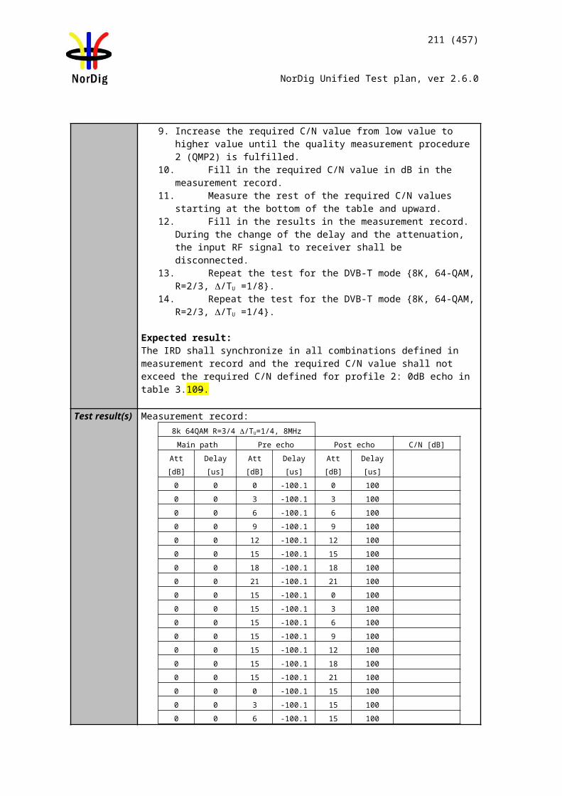
211 (457)
NorDig Unified Test plan, ver 2.6.0
256QAM R2/3 G1/128Table 2. Optional frequencies and signal bandwidths to support.
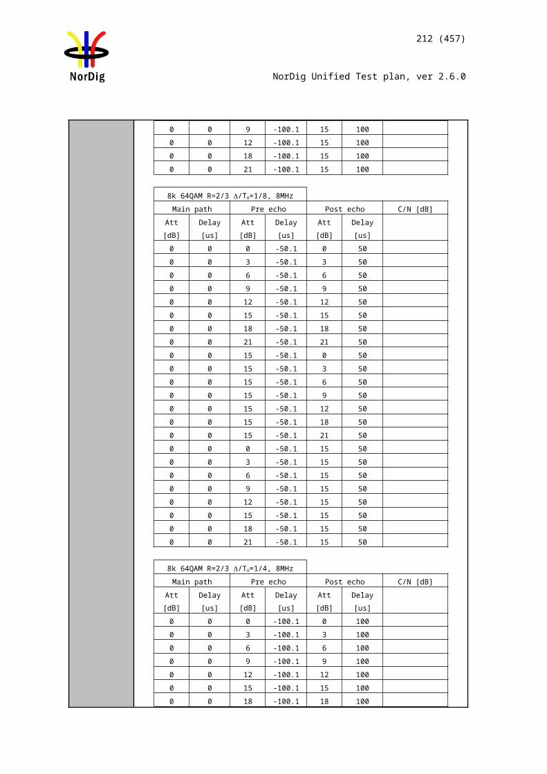
212 (457)
NorDig Unified Test plan, ver 2.6.0
Test Case Task 3:59 DVB-T2: Performance: Minimum IRD Signal Input Levels on 0dB echo channel
Section NorDig Unified 3.4.10.4Requirement The NorDig IRD shall provide QEF reception for the minimum signal levels (Pmin) for
the supported frequency range as stated below (at 290K).For 7 MHz Normal Bandwidth DVB-T/T2 signal: Pmin = -105.7 dBm+NF [dB]+ C/N [dB], andFor 8 MHz Normal Bandwidth DVB-T/T2 signal: Pmin = -105.2 dBm+NF [dB]+ C/N [dB], andFor 1.7 MHz Normal Bandwidth DVB-T2 signal: Pmin = -112.1 dBm+NF [dB]+ C/N [dB], andFor 7 MHz Extended Bandwidth DVB-T2 signal: Pmin = -105.7 dBm+NF [dB]+ C/N [dB], andFor 8 MHz Extended Bandwidth DVB-T2 signal: Pmin = -105.1 dBm+NF [dB]+ C/N [dB], andFor 1.7 MHz Extended Bandwidth DVB-T2 signal: Pmin = -112.1 dBm+NF [dB]+ C/N [dB],
IRD Profile(s) Basic, IRD, DVB-T2Test procedure Purpose of test:
To verify the sensitivity of the receiver on frequency selective channel.
Equipment:
The 0 degree channel center shall be used in fading simulator (see 2.3.4) 0dB echo.
Be careful in impedance matching of cables, adapters and etc.
The 0dB echo profile must be activated when measuring the power level of the signal.
Use Mode A (Single PLP) parameter settings defined in 2.3.7Summary of DVB-T2 modes in DVB-T2 test tasks.
Test procedure for the sensitivity on the frequency selective channel:
Check the different SFN synchronisation issues from 2.3.4 Receiver operability in SFN.
1. Set up the test instruments2. Use the following DVB-T2 mode {32K extended, 256QAM, PP7, R2/3,
GI1/128} and signal bandwidth 8MHz.3. Set the up-converter to frequency 666.0 MHz (K45).
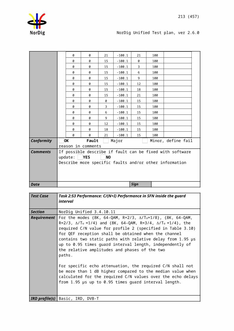
213 (457)
NorDig Unified Test plan, ver 2.6.0
4. Set the fading simulator to 0dB echo profile. (Delay 1.95us, 0 degree phase at channel center and attenuation 0dB for the second path.)
5. Determine the attenuation of the attenuator and the cables.6. Measure the input level to the attenuator.7. Calculate the receiver input signal level. 8. Increase the received input level from low value to higher value until the
quality measurement procedure 2 (QMP2) is fulfilled.9. Fill in the measured value in the measurement record.10. Verify that the channel search founds the services on measured minimum input
signal level.11. Repeat the test for the rest of the DVB-T2 modes with signal bandwidth of
8MHz and 7MHz on the measurement record. DVB-T2 modes with 7MHz signal bandwidth are tested on center frequency 198.5MHz (K8).
12. Optionally, repeat the test for the rest of the DVB-T2 modes with signal bandwidth of 1.7MHz on the measurement record. DVB-T2 mode with 1.7MHz signal bandwidth is tested on center frequency 206.352 MHz (9C).
Expected result:
Required minimum signal level shall be equal or lower in dBm than specified in Table 2.9,Table 2.10,Table 2.11 and Table 2.12 on measured frequencies, DVB-T2 modes and signal bandwidths for all echo delays. If signal bandwidth 1.7MHz is supported, the required minimum signal level shall be equal or lower in dBm than specified in table 2.86 on measured frequency and for DVB-T2 mode.
Test result(s) Measurement record:
P [dBm]DVB-T2 mode / 0dB echo [µs] 10 26 112.1 133 152 212 224 253 256 289 426 48632KE 256QAM PP7 R2/3 G1/128 8MHz32KE 256QAM PP4 R2/3 G1/16 8MHz32KE 256QAM PP4 R3/5 G19/256 8MHz32KN 256QAM PP4 R2/3 G19/256 7MHz32KE 256QAM PP2 R3/4 G1/8 8MHz32KN 256QAM PP2 R3/4 G1/8 7MHz
Table 1. Mandatory frequencies and signal bandwidths to support.
dBmDVB-T2 mode / 0dB echo [µs] 10 263 527
8KN 256QAMR PP2 R2/3 G1/8 1.7MHz
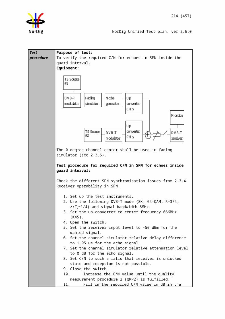
214 (457)
NorDig Unified Test plan, ver 2.6.0
Table 2. Optional frequencies and signal bandwidths to support.
Conformity OK Fault Major Minor, define fail reason in commentsComments If possible describe if fault can be fixed with software update: YES NO
Describe more specific faults and/or other information
Date Sign
Test Case Task 3:60 DVB-T2: Performance: Receiver noise figure on Gaussian channel
Section NorDig Unified 3.4.10.4Requirement The NorDig IRD shall have a noise figure (NF) for supported frequency ranges equal or
better than the values specified in Table 3.12.
IRD Profile(s) Basic, IRD, DVB-T2Test procedure Purpose of test:
To calculate the noise figure of the receiver for gaussian channel.
Equipment:
No equipment needed.
Test procedure for evaluation of the receiver noise figure:
Determine the minimum carrier levels Cmin for the gaussian channel measured in Task 3:58 NOTE NO HYPERLINK USED FOR UPDATE Task 3:58 (DVB-T2: Performance - Minimum IRD Signal Input Levels on Gaussian channel).
Determine the required C/Nmin for the gaussian channel measured in in Task 3:56 NOTE NO HYPERLINK USED FOR UPDATE Task 3:56 (DVB-T2: Performance - C/N performance on Gaussian channel).
Calculate the noise figure NF[dB] for the supported frequencies using the formulas
For 8MHz extended DVB-T2 signal: NF[dB] = N + 105.1dBm = Cmin - C/Nmin + 105.1dBm
For 8MHz normal DVB-T2 signal: NF[dB] = N + 105.2dBm = Cmin - C/Nmin + 105.2dBm
For 7MHz normal DVB-T2 signal: NF[dB] = N + 105.7dBm = Cmin - C/Nmin + 105.7dBm
For 1.7MHz normal DVB-T2 signal: NF[dB] = N + 112.1dBm = Cmin - C/Nmin + 105.7dBm
Expected result:
The noise figure is less than or equal to table 3.12 (1)
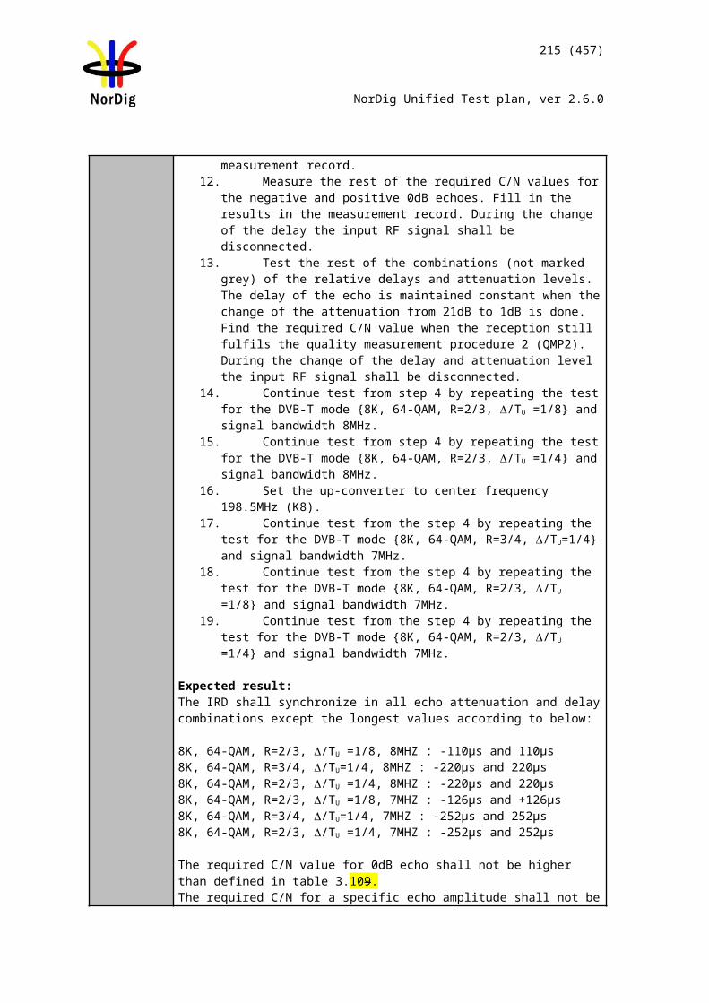
215 (457)
NorDig Unified Test plan, ver 2.6.0
Test result(s) Measurement record:Frequency 177.5 198.5 226.5Channel id K5 K8 K12FFTSignal bandwidth 32k normal
7MHzMode NF [dB]256QAM R3/5256QAM R2/3
Frequency 474.0 522.0 570.0 618.0 666.0 714.0 762.0 810.0 858.0Channel id K21 K27 K33 K39 K45 K51 K57 K63 K69
FFTSignal
bandwidth
32k extended8MHz
Mode NF [dB] 256QAM R3/5256QAM R2/3
Table 1. Mandatory frequencies and signal bandwidths to support.
Frequency 206.352Channel id 9CFFTSignal bandwidth
8k normal1.7MHz
Mode NF [dB]256QAM R2/3
Frequency 114.0 114.5 170.0 170.5 177.5 178.0 226.0 226.5Channel id D1 S2 D8 S10 K5 D9 D15 K12FFTSignal bandwidth
32k normal8MHz
Mode NF [dB]256QAM R2/3
Frequency 233.5 234.0 296.5 298.0 306.0 386.0 466.0Channel id S11 D16 S20 D24 S21 S31 S41FFTSignal bandwidth
32k normal8MHz
Mode NF [dB]256QAM R2/3
Table 2. Optional frequencies and signal bandwidths to support.
Conformity OK Fault Major Minor, define fail reason in commentsComments If possible describe if fault can be fixed with software update: YES NO
Describe more specific faults and/or other information
Date Sign
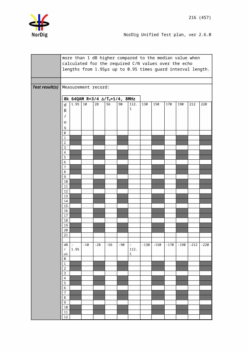
216 (457)
NorDig Unified Test plan, ver 2.6.0
Test Case Task 3:61 DVB-T2: Performance: Maximum Receiver Signal Input Levels
Section NorDig Unified 3.4.10.5 and 3.4.10.6Requirement The NorDig IRD shall provide QEF reception for DVB-T and DVB-T2 signals up to a
level of –35dBm. The maximum analogue TV signal input level is restricted to –20 dBm defined as the r.m.s (root mean square) value of the vision carrier at peaks of the modulated envelope. The DVB-T signal input level is valid for the modes {8K, 64-QAM, R=2/3, /Tu=1/8}, {8K, 64-QAM, R=2/3, /Tu =1/4} and {8K, 64-QAM, R=3/4, /Tu =1/4}.
The DVB-T2 signal input level is valid for the modes shown in NorDig Specification (1).
IRD Profile(s) Basic, IRD, DVB-T2Test procedure Purpose of test:
To test that the receiver is able to handle high RF signals.
Equipment:
Use Mode A (Single PLP) parameter settings defined in 2.3.7Summary of DVB-T2 modes in DVB-T2 test tasks.
Test procedure
1. Set up the test instruments.2. Determine the attenuation of the attenuator.3. Use the following mode {32K extended, 256-QAM rotated, PP7,R=3/4,
/TU=1/128}.4. Set the up-converter to channel 45.5. Determine the attenuation of the attenuator and the cables.6. Turn on the receiver.7. Check that the picture is decoded correctly.8. Calculate the receiver input signal level as a function of attenuation in
attenuator. 9. Increase the receiver input signal level until the quality measurement procedure
1 (QMP1) is fulfilled.10. Fill in the result in the measurement record.
Expected result:
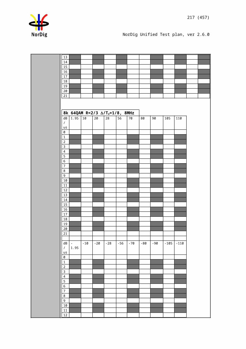
Channel B
TS source
DVB-T2 receiver
MonitorDVB-T2 modulator
ATT I
ATT C
TS source
DVB-T/T2 modulator
Upconverter (interference)
Channel A
Spectrumanalysator
Upconverter (wanted)
217 (457)
NorDig Unified Test plan, ver 2.6.0
The reception shall be QEF for input level higher than or equal to –35dBm for defined DVB-T2 modes.
Test result(s) Measurement record:
Mode Requirement dBm Result32K extended, 256-QAM rotated, PP7,R=3/4, /TU=1/128
-35
Conformity OK Fault Major Minor, define fail reason in commentsComments If possible describe if fault can be fixed with software update: YES NO
Describe more specific faults and/or other information
Date Sign
Test Case Task 3:62 DVB-T2: Performance: Immunity to “digital” signals in Other Channels
Section NorDig Unified 3.4.10.7.1Requirement The NorDig IRD shall, for the supported frequency ranges, permit an interfering DVB-T
or DVB-T2 signal with a minimum interference to signal level ratio (I/C) as stated in the NorDig Specification (1) while maintaining QEF reception.
The requirements in this paragraph refer, for DVB-T, to the modes {8K, 64-QAM, R=2/3, /Tu =1/8} and {8K, 64-QAM, R=2/3, /Tu =1/4} and {8K, 64-QAM, R=3/4, /Tu =1/4} and for DVB-T2 to the modes given in NorDig Specification.
IRD Profile(s) Basic, IRD, DVB-T2Test procedure Purpose of test:
To verify the QEF reception for digtal signal interference on adjacent or other channels.
Equipment:
Verify that the digital signal on the adjacent or the other channels don’t have too high
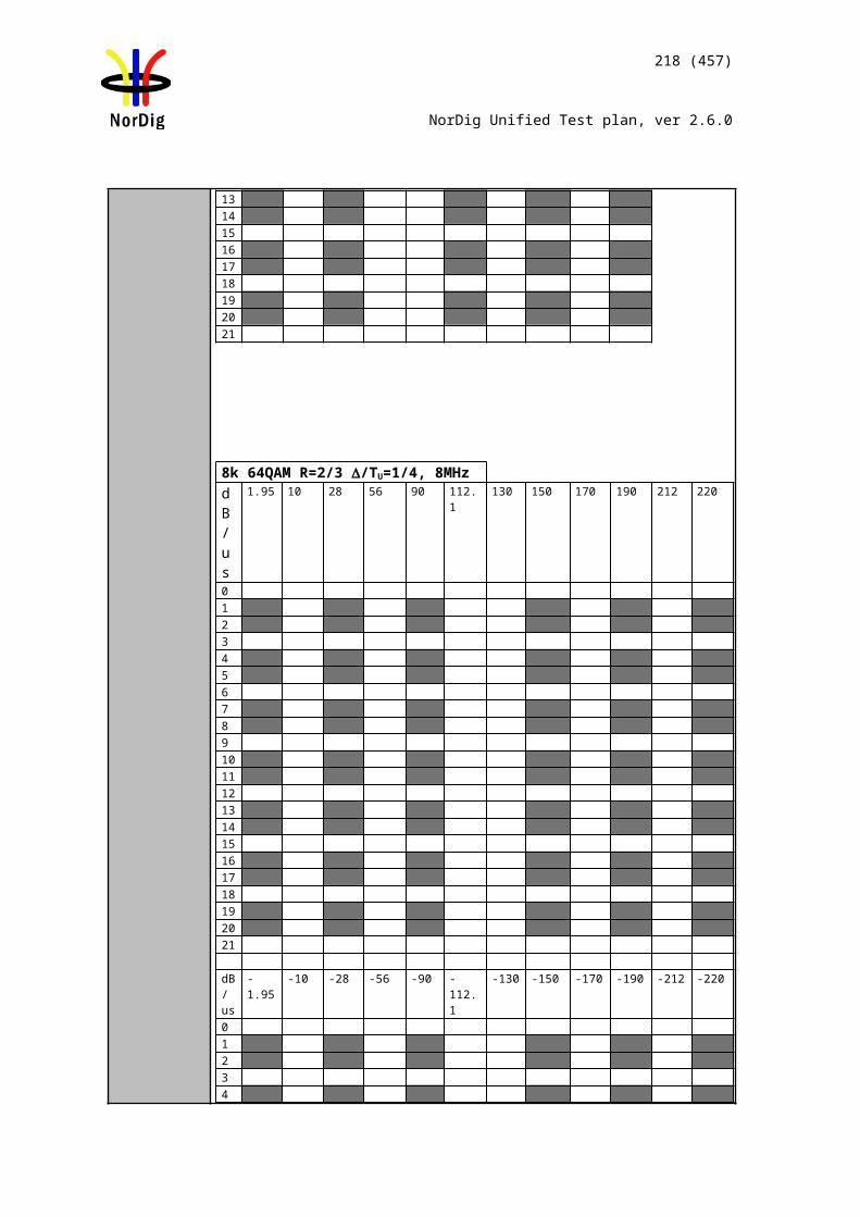
218 (457)
NorDig Unified Test plan, ver 2.6.0
shoulders, which could cause out-of-band emissions in the reception of the wanted digital TV signal.
Worst case is when wanted and interference signals are DVB-T2 modulated in extended carrier mode in adjacent channels. This test can be performed using DVB-T modulated interferer, because the performance difference is expected to be neglible. When using DVB-T modulated interferer, signal bandwidth of the DVB-T modulated signal must be selected according to frequency range, except for the signal bandwidth 1.7MHz, which is not supported in the DVB-T system.
Many of the European countries are going to free channel 61 and upwards to other types of services than TV. In this test a DVB-T interferer is used on channels over 60 in order to measure the interference from DVB-T system for comparison reasons.
Use Mode A (Single PLP) parameter settings defined in 2.3.7Summary of DVB-T2 modes in DVB-T2 test tasks.
Test procedure:
1. Set up the test instruments2. Use the following DVB-T2 mode {32K extended, 256-QAM rotated, PP4,
R=3/4, /TU=1/16} and signal bandwidth 8MHz.3. Set the channel A up-converter to 666.0MHz (K45).4. Set the channel B up-converter to 674.0MHz (K46).5. Set the receiver input level for the DVB-T2 signal in channel B to -20 dBm.6. Decrease the DVB-T2 signal level in channel A to a signal level when the
quality measurement procedure 2 (QMP2) is still fulfilled.7. Fill in the measured signal level difference between channel A and channel B
signals in dB in measurement record. 8. Repeat the test when the channel B up-converter is set to frequencies 658.0
MHz (K44), 650.0 MHz (K43), 682.0 MHz (K47).9. Repeat the test according to procedure above for the image channel1) . Set the
receiver input level for the DVB-T2 signal in channel B to –20dBm.10. Set the channel A up-converter to 786.0MHz (K60).11. Set the channel B up-converter to 794.0MHz (K61).12. Set the receiver input level for the DVB-T2 signal in channel B to -20 dBm.13. Decrease the DVB-T2 signal level in channel A to a signal level when the
quality measurement procedure 2 (QMP2) is still fulfilled.14. Fill in the measured signal level difference between channel A and channel B
signals in dB in measurement record. 15. Repeat the test when the channel B up-converter is set to frequencies 770.0
MHz (K58), 778.0 MHz (K59), 802.0 MHz (K62).16. Repeat the test according to procedure above for the image channel1) . Set the
receiver input level for the DVB-T2 signal in channel B to –20dBm.17. Change the signal bandwidth to 7MHz.18. Use the following DVB-T2 mode {32K normal, 256-QAM rotated, R=3/4,
PP2,/TU=1/8} and signal bandwidth 7MHz.19. Set the channel A up-converter to frequency 198.5 MHz (K8).20. Set the channel B up-converter to frequency 205.5 MHz (K9). 21. Set the receiver input level of the DVB-T2 signal in channel B to -20dBm. 22. Decrease the DVB-T2 signal level in channel A to a signal level when the
quality measurement procedure 2 (QMP2) is fulfilled.23. Fill in the measured signal level difference between channel A and channel B
signals in dB in measurement record. 24. Repeat the test when the channel B up-converter is set to frequencies 191.5
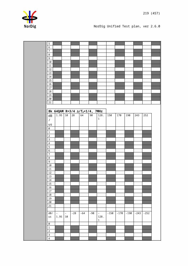
219 (457)
NorDig Unified Test plan, ver 2.6.0
MHz (K7), 184.5 MHz (K6) and 212.5 MHz (K10).If receiver supports optional frequency ranges and signal bandwidths, repeat the test for the optional frequencies and signal bandwidths. For 1.7MHz DVB-T2 signal use DVB-T2 mode {8K normal, 64QAM, R=2/3, PP2, /TU=1/8} corresponding signal bandwidth 1.535 MHz.
1) Example: if intermediate frequency IF is 36.15MHz, the image channel is calculated for channel 45 as 666MHz + 2 * 36.15MHz = 738.3MHz which is close to channel 54.
Expected result:
The wanted DVB-T2 signal shall be QEF for the interference signal levels specified for DVB-T2 modes, signal bandwidths and supported frequencies.
Test result(s) Measurement record:
7 MHz signal bandwidthInterferer center frequency [MHz] 184.5 191.5 205.5 212.5DVB-T2 mode / Channel id K6 K7 K9 K1032K normal,256-QAM rotated, PP2R=3/4, /TU =1/8
Table 1. Mandatory VHF Band III frequencies and signal bandwidth to support
8 MHz signal bandwidthInterferer center frequency [MHz] 650.0 658.0 674.0 682.0 738.0DVB-T2 mode / Channel id K43 K44 K46 K47 K5432K extended,256-QAM rotated,PP4, R=2/3, /TU =1/16
Table 2. Mandatory UHF Band IV/V frequencies and signal bandwidth to support
8 MHz signal bandwidthInterferer center frequency [MHz] 770.0 778.0 794.0 802.0 810.0DVB-T2 mode / Channel id K58 K59 K61 K62 K6332K extended,256-QAM rotated,PP4,R=2/3, /TU =1/16
Table 3. Mandatory UHF Band IV/V frequencies and signal bandwidth to support
7 MHz signal bandwidthCenter frequency [MHz] 128.5 135.5 149.5 156.5DVB-T2 mode / Channel id S4 S5 S7 S832K normal,256-QAM rotated, PP2,
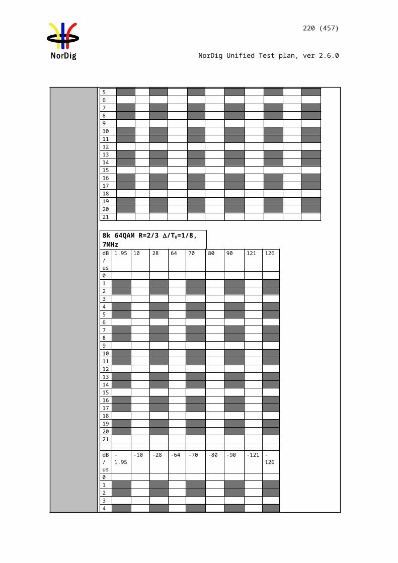
220 (457)
NorDig Unified Test plan, ver 2.6.0
R=3/4, /TU =1/8Table 4. Optional VHF S Band I frequencies and signal bandwidth to support
8 MHz signal bandwidthCenter frequency [MHz] 122.0 130.0 146.0 154.0DVB-T2 mode / Channel id D2 D3 D5 D632K extended,256-QAM rotated,PP4, R=2/3, /TU =1/16
Table 5. Optional VHF S Band I frequencies and signal bandwidth to support
8 MHz signal bandwidthCenter frequency [MHz] 186.0 194.0 210.0 218.0DVB-T2 mode / Channel id D10 D11 D13 D1432K extended,256-QAM rotated, PP4R=2/3, /TU =1/16
Table 6. Optional VHF Band III frequencies and signal bandwidth to support
7 MHz signal bandwidthCenter frequency [MHz] 247.5 254.5 268.5 275.5DVB-T2 mode / Channel id S13 S14 S16 S1732K normal,256-QAM rotated, PP2R=3/4, /TU =1/8
Table 7. Optional VHF S Band II frequencies and signal bandwidth to support
8 MHz signal bandwidthCenter frequency [MHz] 250.0 258.0 274.0 282.0DVB-T2 mode / Channel id D18 D19 D21 D2232K extended,256-QAM rotated,PP4 R=2/3, /TU =1/16
Table 8. Optional VHF S Band II frequencies and signal bandwidth to support
8 MHz signal bandwidthCenter frequency [MHz] 370.0 378.0 394.0 402.0DVB-T2 mode / Channel id S29 S30 S32 S3332K extended,256-QAM rotated,PP4 R=2/3, /TU =1/16
Table 9. Optional UHF S Band III frequencies and signal bandwidth to support
1.7 MHz signal bandwidthCenter frequency [MHz] 202.928 204.640 208.064 209.936
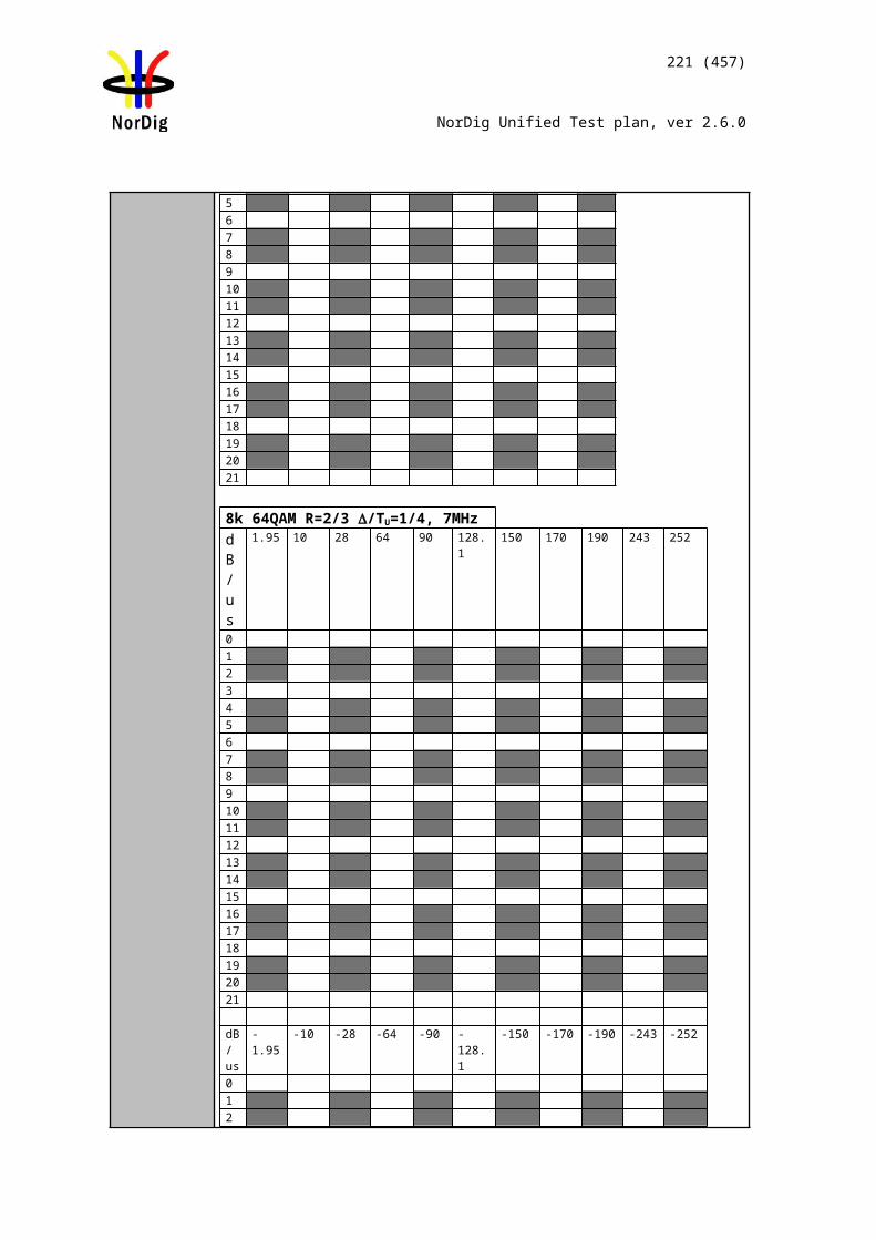
221 (457)
NorDig Unified Test plan, ver 2.6.0
DVB-T2 mode / Channel id 9A 9B 9D 10A8K normal,256-QAM rotated, PP2,R=2/3, /TU =1/8
Table 10. Optional VHF Band III frequencies and signal bandwidth to support
Conformity OK Fault Major Minor, define fail reason in commentsComments If possible describe if fault can be fixed with software update: YES NO
Describe more specific faults and/or other information
Date Sign
Test Case Task 3:63 DVB-T2: Performance: Immunity to “LTE 700 MHz” signals in Other Channels
Section NorDig Unified 3.4.10.7.2Requirement The terrestrial NorDig IRD and IRD-T2 shall, for the supported frequency ranges,
permit an interfering 4G (LTE) “700MHz” signal with a minimum interference to signal level ratio (I/C) as stated in the Table 3.178 [1] while maintaining QEF reception.
The power of the interfering LTE signal, both BS and UE, varies with a traffic load and traffic type. The signal power of the LTE signal is defined as the power during the active part of the time varying LTE signal, referred to as the licensed power level (I).
The I/C values shall (1) be fulfilled for LTE signals with traffic loads from 0% to 100 % (BS) and for traffic loads from low bit rate to high bit rate (UE). Low traffic loads can be the most demanding ones. The minimum I/C requirement shall be fulfilled for interfering licensed power level signal levels in the range of -25 dBm in case of UE signals and -15dBm in case of BS signals defined as licensed power of interfering signal, at the input of the IRD.
The requirements in this paragraph refer, for DVB-T, to following modes {FFT size, modulation, code rate, guard interval, bandwidth}; {8K, 64-QAM, R=2/3, /Tu =1/8, 8MHz} and {8K, 64-QAM, R=2/3, /Tu =1/4, 8MHz} and {8K, 64-QAM, R=3/4, /Tu =1/4, 8MHz} and and for DVB-T2 to the modes {FFT size, modulation, pilot pattern, code rate, guard interval, bandwidth}{32KE, 256-QAM R, PP4, R=2/3, /Tu =1/16, 8MHz}{32KE, 256-QAM R, PP4, R=3/5, /Tu =19/256, 8MHz}{32KN, 256-QAM R, PP4, R=2/3, /Tu =19/256, 7MHz}
IRD Profile(s) Basic, IRD, DVB-T2Test procedure Purpose of test:
To verify the QEF reception for LTE 700 MHz signal interference on adjacent or other channels.
Equipment:
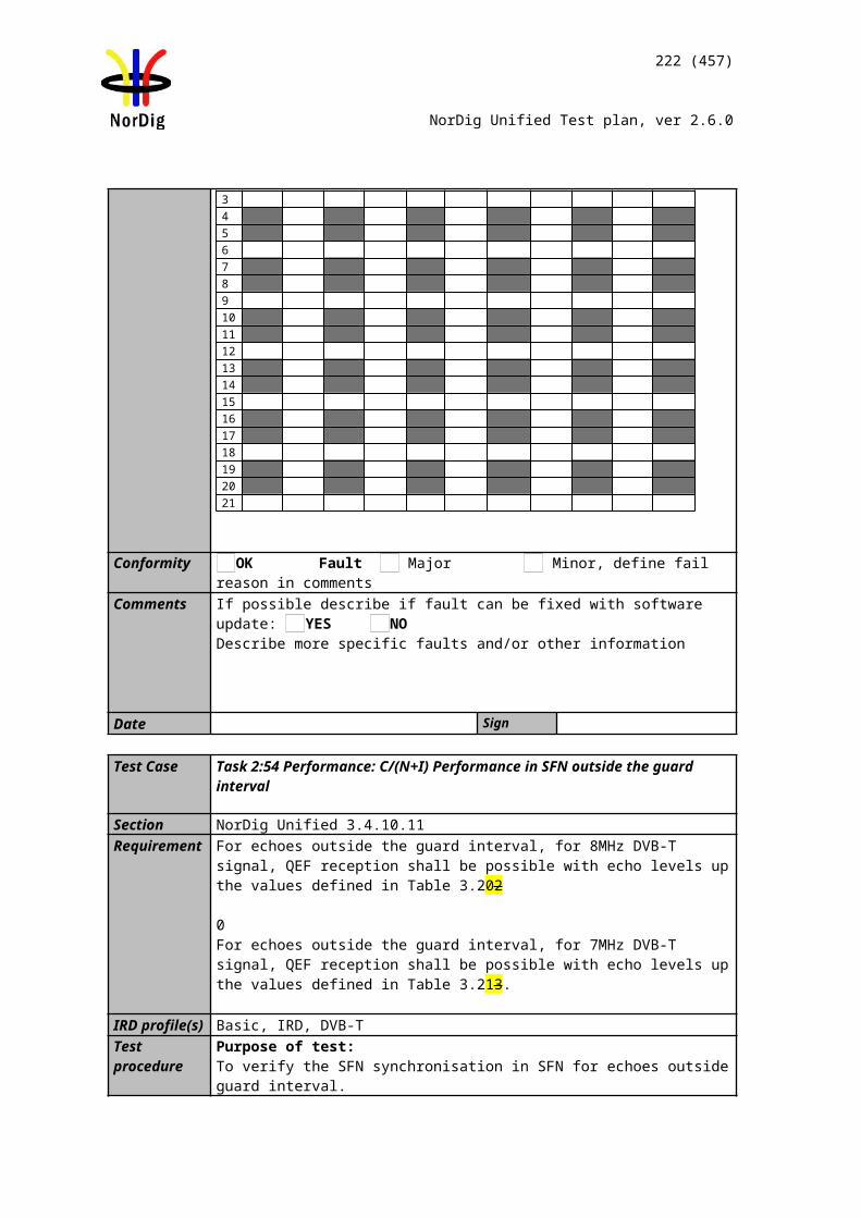
Channel B
TS source
IRD MonitorDVB-T2 modulator
ATT I
ATT C
LTE source
LTE modulator
Upconverter (interference)
Channel A
Spectrumanalysator
Upconverter (wanted)
222 (457)
NorDig Unified Test plan, ver 2.6.0
Verify that the interfering LTE signal on the adjacent or the other channels don’t have too high shoulders, which could cause out-of-band emissions in the reception of the wanted digital TV signal.
From IRD point of view most demanding LTE signal might be that with low traffic load.
The LTE transmission is generated by using following LTE signal characteristics: BS 0% traffic load (LTE_BS-idle_V3_synth.wv)UE Video stream traffic (short_UE-Video-Stream_V2.wv)
Files in I/Q file format specified above are available on the ETSI website http://www.etsi.org/deliver/etsi_en/303300_303399/303340/01.01.02_60/en_303340v010102p0.zip
or if not available, they can be found on the NorDig homepage.
Use Mode A (Single PLP) and Lf parameter settings defined in Table 2.18.
Test procedure:
1. Set up the test instruments2. Use the following DVB-T2 mode {32KE, 256-QAM R, PP4, R=2/3, G =1/16,
8MHz}3. Set the channel A up-converter to 690.0MHz (K48).4. Set the channel B up-converter to 708.0MHz .5. Set the LTE interefer to UE Video traffic mode.6. Set the receiver input level for the LTE signal in channel B to -25 dBm.7. Decrease the wanted signal level in channel A to a signal level when the quality
measurement procedure 2 is still fulfilled.8. Fill in the measured signal level difference between channel A and channel B
signals in dB in measurement record. 9. Repeat the test when the channel B up-converter is set to frequencies 718.0
MHz, 728.0 MHz.10. Set the channel B up-converter to 763.0MHz.11. Set the LTE interefer to BS 0% traffic load mode.12. Set the receiver input level for the LTE signal in channel B to -15 dBm.13. Decrease the wanted signal level in channel A to a signal level when the quality
measurement procedure 2 is still fulfilled.14. Fill in the measured signal level difference between channel A and channel B
signals in dB in measurement record. 15. Repeat the test when the channel B up-converter is set to frequencies 773.0
MHz, 783.0 MHz.
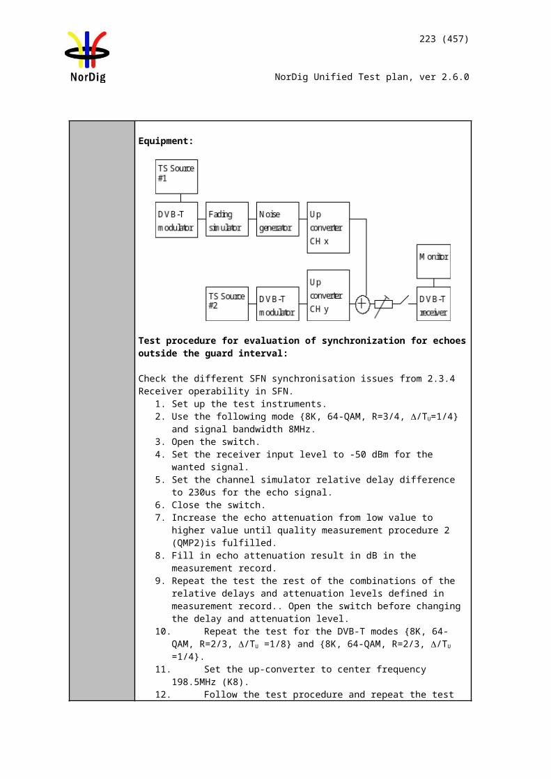
223 (457)
NorDig Unified Test plan, ver 2.6.0
16. Repeat the test for the DVB-T2 mode {32KE, 256-QAM R, PP4, R=3/5, G=19/256, 8MHz}.
Expected result:
The wanted DVB-T2 signal shall be QEF for the interference signal levels as specified.
Test result(s) Measurement record:
I/C [dB]Interferer centre frequency [MHz] 708.0 718.0 728.032KE, 256-QAM R, PP4, R=2/3, /Tu =1/16, 8MHz32KE, 256-QAM R, PP4, R=3/5, /Tu =19/256, 8MHz
Table 1. UE Video stream traffic interferer
I/C [dB]Interferer centre frequency [MHz] 763.0 773.0 783.032KE, 256-QAM R, PP4, R=2/3, /Tu =1/16, 8MHz32KE, 256-QAM R, PP4, R=3/5, /Tu =19/256, 8MHz
Table 2. BS 0% traffic load interferer
Conformity OK Fault Major Minor, define fail reason in commentsComments If possible describe if fault can be fixed with software update: YES NO
Describe more specific faults and/or other information
Date Sign
Test Case Task 3:64 DVB-T2: Performance: Immunity to “LTE 800 MHz” signals in Other Channels
Section NorDig Unified 3.4.10.7.1Requirement The DVB-T and DVB-T2 IRD shall, for the supported frequency ranges, permit an
interfering LTE signal with a minimum interference to signal level ratio (I/C) as stated in the table below while maintaining QEF reception.
The power of the LTE signal, both BS and UE, varies with a traffic load. The signal power of the LTE signal is defined as the power during the active part of the time varying LTE signal. The I/C values shall be fulfilled for traffic loads 0% to 100 % (BS) and for traffic loads from low bit rate to high bit rate (UE). Low traffic loads can be the most demanding ones. The minimum I/C requirement shall be fulfilled for -15dBm defined as licensed power of interfering signal, at the input of the IRD.
The requirements in this paragraph refer, for DVB-T, to the modes {8K, 64-QAM, R=2/3, /Tu =1/8, 8MHz} and {8K, 64-QAM, R=2/3, /Tu =1/4, 8MHz} and {8K, 64-QAM, R=3/4, /Tu =1/4, 8MHz} and for DVB-T2 to the modes {32KE, 256-QAM R, PP4, R=2/3, /Tu =1/16, 8MHz}{32KE, 256-QAM R, PP4, R=3/5, /Tu =19/256, 8MHz}{32KN, 256-QAM R, PP4, R=2/3, /Tu =19/256, 7MHz}.
IRD Profile(s) Basic, IRD, DVB-T2
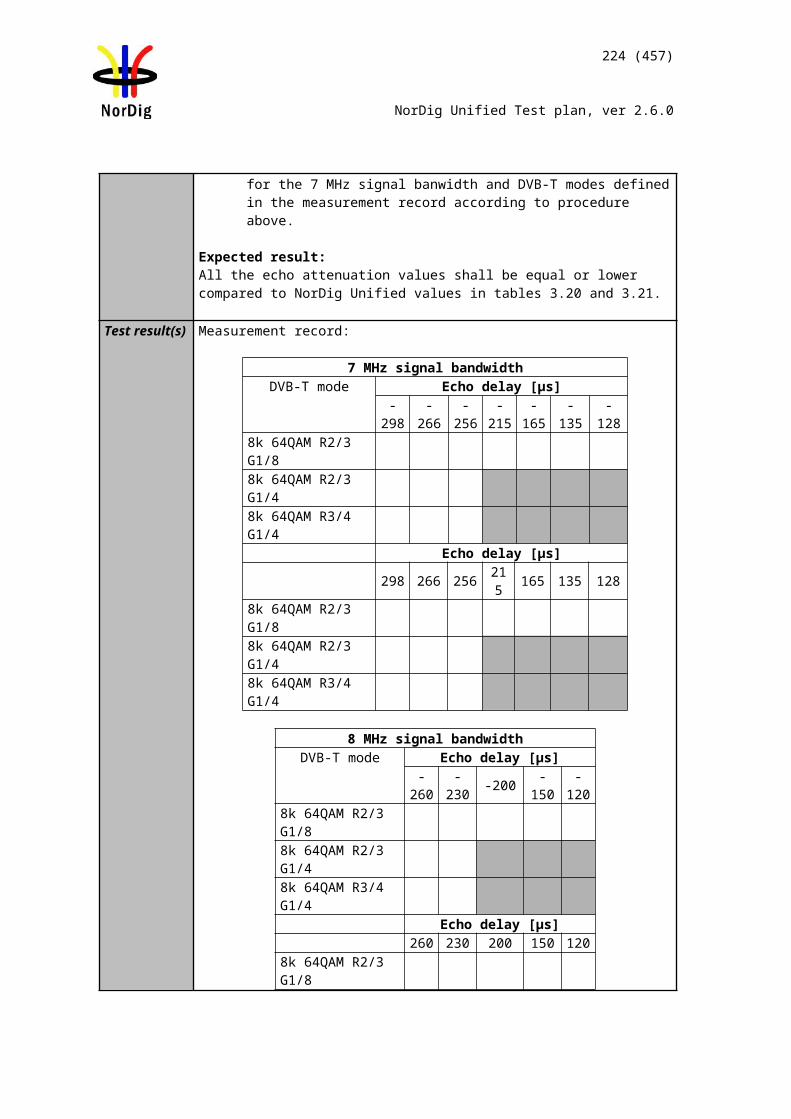
Channel B
TS source
IRD MonitorDVB-T2 modulator
ATT I
ATT C
LTE source
LTE modulator
Upconverter (interference)
Channel A
Spectrumanalysator
Upconverter (wanted)
224 (457)
NorDig Unified Test plan, ver 2.6.0
Test procedure Purpose of test:To verify the QEF reception for LTE signal interference on adjacent or other channels.
Equipment:
Verify that the interfering LTE signal on the adjacent or the other channels don’t have too high shoulders, which could cause out-of-band emissions in the reception of the wanted digital TV signal.
From IRD point of view most demanding LTE signal might be that with low traffic load.
The LTE transmission is generated by using following LTE signal characteristics: LTE_BS-idle_V2.wv (BS 0% traffic load)LTE_UE_1Mbs_V2.wv (UE 1 MBit/s traffic load)
Files in I/Q file format are available on NorDig homepage.
Use Mode A (Single PLP) and Lf parameter settings defined by Teracom for the modes.
Test procedure:
1. Set up the test instruments2. Use the following DVB-T mode {32KE, 256-QAM R, PP4, R=2/3, /Tu
=1/16, 8MHz}3. Set the channel A up-converter to 786.0MHz (K60).4. Set the channel B up-converter to 796.0MHz .5. Set the LTE interefer to BS 0% traffic load mode.6. Set the receiver input level for the LTE signal in channel B to -15 dBm.7. Decrease the wanted signal level in channel A to a signal level when the quality
measurement procedure 2 is still fulfilled.8. Fill in the measured signal level difference between channel A and channel B
signals in dB in measurement record. 9. Repeat the test when the channel B up-converter is set to frequencies 806.0
MHz, 816.0 MHz.10. Set the channel B up-converter to 837.0MHz.11. Set the LTE interefer to UE 1 MBit/s traffic load mode. 12. Set the receiver input level for the LTE signal in channel B to -15 dBm.13. Decrease the wanted signal level in channel A to a signal level when the quality
measurement procedure 2 is still fulfilled.14. Fill in the measured signal level difference between channel A and channel B
signals in dB in measurement record. 15. Repeat the test when the channel B up-converter is set to frequencies 847.0
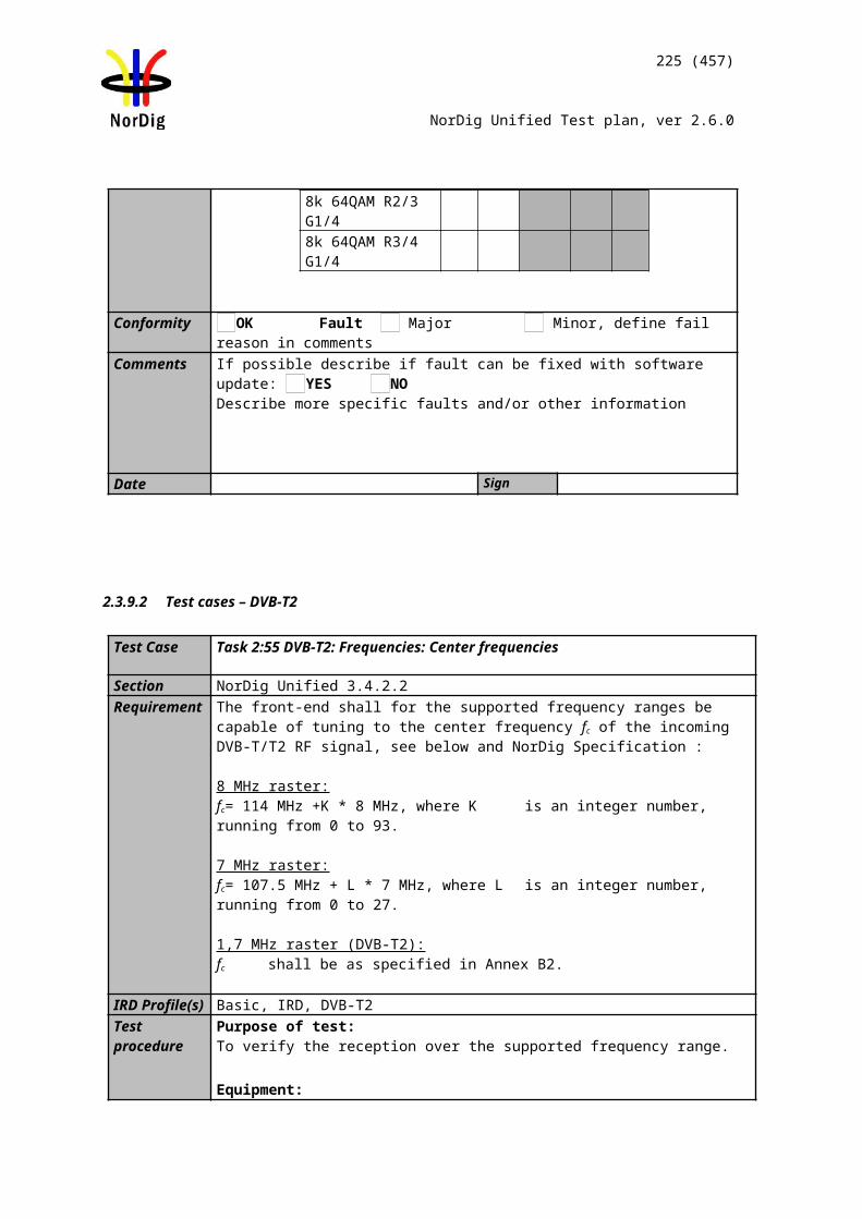
225 (457)
NorDig Unified Test plan, ver 2.6.0
MHz, 857.0 MHz.16. Repeat the test for the DVB-T2 mode {32KE, 256-QAM R, PP4, R=3/5, /Tu
=19/256, 8MHz}.
Expected result:
The wanted DVB-T2 signal shall be QEF for the interference signal levels as specified.
Test result(s) Measurement record:
I/C [dB]Interferer centre frequency [MHz] 796.0 806.0 816.032KE, 256-QAM R, PP4, R=2/3, /Tu =1/16, 8MHz32KE, 256-QAM R, PP4, R=3/5, /Tu =19/256, 8MHz
Table 1. BS 0% interferer I/C [dB]
Interferer centre frequency [MHz] 837.0 847.0 857.032KE, 256-QAM R, PP4, R=2/3, /Tu =1/16, 8MHz32KE, 256-QAM R, PP4, R=3/5, /Tu =19/256, 8MHz
Table 2. UE 1 Mbit/s interferer
Conformity OK Fault Major Minor, define fail reason in commentsComments If possible describe if fault can be fixed with software update: YES NO
Describe more specific faults and/or other information
Date Sign
Test Case Task 3:65 DVB-T2: Performance: Performance in Time-Varying Channels
Section NorDig Unified 3.4.10.9Requirement The NorDig IRD shall be able to operate with all signal time variations that naturally
exist in connection with fixed roof-top reception (e.g. mast sway, antenna sway) and in-house portable reception (e.g. people walking around the receiving antenna). None of the above mentioned performance parameters should be significantly negatively affected when such channel time variations exist.
The increase in required C/N for QEF reception shall be less than 3 dB for a 0 dB echo with frequency separation equal to 20 Hz and a delay of 20 µs, corresponding to a Doppler shift of +/- 10 Hz (after AFC), compared to a 0 dB echo with frequency separation equal to 1 Hz and a delay of 20 µs, corresponding to a Doppler shift of +/- 0.5 Hz (after AFC). The requirements in this paragraph refer for DVB-T to the modes {8K, 64-QAM, R=2/3, /Tu =1/8} and {8K, 64-QAM, R=2/3, /Tu =1/4}.
The increase in required C/N for QEF reception shall be less than 3 dB for a 0 dB echo with frequency separation equal to 10 Hz and a delay of 20 µs, corresponding to a Doppler shift of +/- 5 Hz (after AFC), compared to a 0 dB echo with frequency separation equal to 1 Hz and a delay of 20 µs, corresponding to a Doppler shift of +/- 0.5 Hz (after AFC). The requirement in this paragraph refer for DVB-T to the mode {8K, 64-QAM, R=3/4, /Tu =1/4} and for DVB-T2 to the modes given in (1). For 1.7 MHz these DVB-T2 modes apply as well, except that the FFT size is 8K
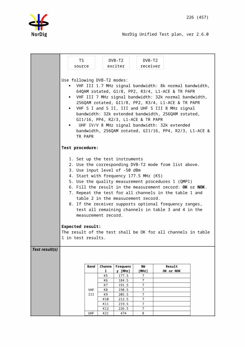
226 (457)
NorDig Unified Test plan, ver 2.6.0
IRD Profile(s) Basic, IRD, DVB-T2Test procedure Purpose of test:
To verify the reception on a channel where time variations exists.
1.7MHz BW DVB-T2 modes are optional to test.
Equipment:
The 0 degree channel center shall be used in fading simulator (see 2.3.5). This is valid for 0Hz doppler shift.
Use Mode A (Single PLP) parameter settings defined in 2.3.7Summary of DVB-T2 modes in DVB-T2 test tasks.
Test procedure:
1. Set up the test instruments. 2. Use the following DVB-T2 mode: {32K extended, 256-QAM rotated, R=3/4,
/TU=1/128}. 3. Use channel K45 (666MHz).4. Configure path 1 to type of static, attenuation 0dB, delay 0µs. 5. Configure path 2 to type of pure Doppler, attenuation 0dB, delay 20µs and
frequency separation to 0Hz. 6. Set the receiver input level to -50 dBm. 7. Increase the C/N from low value to higher value until the quality measurement
procedure 2 (QMP2) is fulfilled. 8. Fill in the measured value in dB in the measurement record. 9. Repeat the test for the rest of the frequency separation values in the
measurement record. Be careful of value which is configured in fading simulator. It can be speed, Doppler or frequency separation.
10. Fill the C/N result in the measurement record.11. Repeat the test for the rest of the DVB-T2 modes in measurement record.
Expected result:
For the DVB-T2 modes the increase in the required C/N shall be less than 3dB for 0dB 20µs echo from frequency separation 1Hz to 10Hz.
Test result(s) Measurement record:
Mode 0dB echo Frequency C/N [dB]
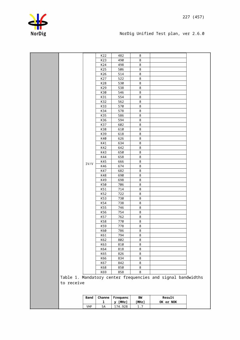
227 (457)
NorDig Unified Test plan, ver 2.6.0
delay [µs] separation [Hz]
32K extended, 256QAM, PP2, R=3/4, /TU =1/8, 8MHz, 666MHz
20µs 0Hz
32K extended, 256QAM, PP2, R=3/4, /TU =1/8, 8MHz, 666MHz
20µs 1Hz
32K extended, 256QAM, PP2, R=3/4, /TU =1/8, 8MHz, 666MHz
20µs 5Hz
32K extended, 256QAM, PP2, R=3/4, /TU =1/, 8MHz, 666MHz
20µs 10Hz
32K extended, 256QAM, PP4, R=3/5, /TU =19/256, 8MHz, 666MHz
20µs 0Hz
32K extended, 256QAM, PP4, R=3/5, /TU =19/256, 8MHz, 666MHz
20µs 1Hz
32K extended, 256QAM, PP4, R=3/5, /TU =19/256, 8MHz, 666MHz
20µs 5Hz
32K extended, 256QAM, PP4, R=3/5, /TU =19/256, 8MHz, 666MHz
20µs 10Hz
32K extended, 256QAM, PP4, R=2/3, /TU =1/16, 8MHz, 666MHz
20µs 0Hz
32K extended, 256QAM, PP4, R=2/3, /TU =1/16, 8MHz, 666MHz
20µs 1Hz
32K extended, 256QAM, PP4, R=2/3, /TU =1/16, 8MHz, 666MHz
20µs 5Hz
32K extended, 256QAM, PP4, R=2/3, /TU =1/16, 8MHz, 666MHz
20µs 10Hz
32K normal, 256QAM, PP4, R=2/3, /TU =19/256, 7MHz, 198.5MHz
20µs 0Hz
32K normal, 256QAM, PP4, R=2/3, /TU =19/256, 7MHz, 198.5MHz
20µs 1Hz
32K normal, 256QAM, PP4, R=2/3, /TU =19/256, 7MHz, 198.5MHz
20µs 5Hz
32K normal, 256QAM, PP4, R=2/3, /TU =19/256, 7MHz, 198.5MHz
20µs 10Hz
32K normal, 256QAM, PP2, R=3/4, /TU =1/8, 7MHz, 198.5MHz
20µs 0Hz
32K normal, 256QAM, PP2, R=3/4, /TU =1/8, 7MHz, 198.5MHz
20µs 1Hz
32K normal, 256QAM, PP2, R=3/4, /TU =1/8, 7MHz, 198.5MHz
20µs 5Hz
32K normal, 256QAM, PP2, R=3/4, /TU =1/8, 7MHz, 198.5MHz
20µs 10Hz
Table 1. Mandatory DVB-T2 modes
8K normal,256QAM, PP2, R=2/3, /TU =1/8, 1.7MHz, 206.352MHz
20µs 0Hz
8K normal,256QAM, PP2, R=2/3, /TU =1/8, 1.7MHz, 206.352MHz
20µs 1Hz
8K normal,256QAM, PP2, R=2/3, /TU =1/8, 1.7MHz, 206.352MHz
20µs 5Hz
8K normal, 256QAM, PP2, R=2/3, /TU =1/8, 20µs 10Hz
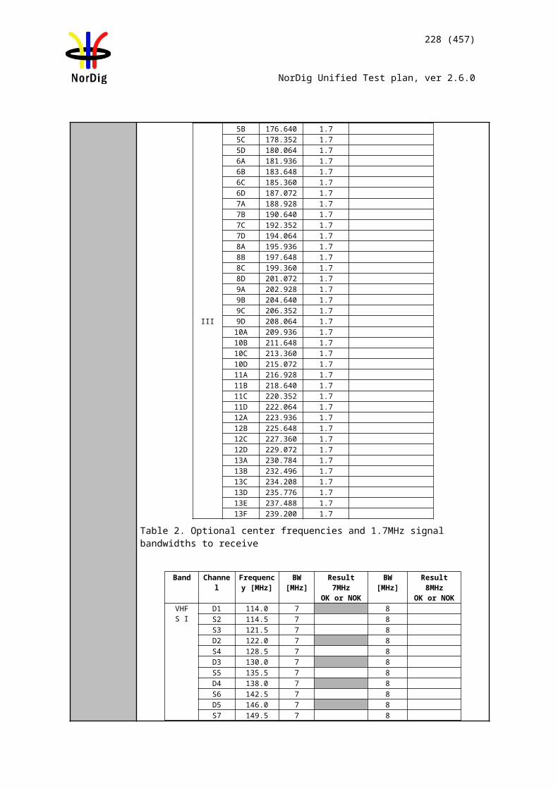
228 (457)
NorDig Unified Test plan, ver 2.6.0
1.7MHz, 206.352MHzTable 2. Optional DVB-T2 modes
Conformity OK Fault Major Minor, define fail reason in commentsComments If possible describe if fault can be fixed with software update: YES NO
Describe more specific faults and/or other information
Date Sign
Test Case Task 3:66 DVB-T2: Performance: Synchronisation for varying echo power levels in SFN
Section NorDig Unified 3.4.10.910Requirement For the DVB-T modes {8K, 64-QAM, R=2/3, ∆/Tu=1/8}, {8K, 64-QAM, R=2/3, ∆/Tu
=1/4} and {8K, 64-QAM, R=3/4, ∆/Tu =1/4}, the required C/N value, specified in NorDig specification, for QEFreception shall be obtained when the channel contains two paths with relative delay from 1.95 µs up to 0.95 times guard interval length and the relative power levels of the two paths are dynamically varying including 0dB echo level crossing. The C/N value is defined at 0 dB level crossing. For the DVB-T2 modes given in Table 23.94, the required C/N value, specified in NorDig Specification, for QEF reception shall be obtained when the channel contains two paths with relative delay from 1.95 µs up to 0.95 times guard interval length and the relative power levels of the two paths are dynamically varying including 0dB echo level crossing. The C/N value is defined at 0 dB level crossing.
IRD Profile(s) Basic, IRD, DVB-T2Test procedure Purpose of test:
To verify the SFN synchronisation when the amplitude of the echo compared to the amplitude of the direct signal varies in a function of time.
1.7 MHz DVB-T2 modes not tested.
Equipment:
The 0 degree channel center shall be used in fading simulator (see 2.3.5).
Use Mode A (Single PLP) parameter settings defined in 2.3.7 Summary of DVB-T2 modes in DVB-T2 test tasks.
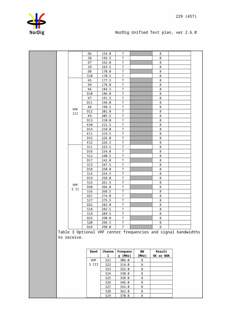
229 (457)
NorDig Unified Test plan, ver 2.6.0
Test procedure for variations of the echo attenuation in a function of time:
Check the different SFN synchronisation issues from 2.3.4 Receiver operability in SFN.
1. Set up the test instruments.2. Use the following mode 32K extended, 256QAM, PP74, R=2/3, /TU=1/128, 8
MHz.3. Use channel K45 (666MHz).4. Open the switch.5. Configure the first path signal (direct) with following parameters: 0dB
attenuation and 0µs delay. 6. Configure the second path signal (1st echo) with following parameters: 0dB
attenuation and first delay value from the measurement record. 7. Set the receiver input level to -50 dBm.8. Configure the third path signal (2nd echo) with following parameters: 1dB
attenuation and delay same as for the second path and 0.1Hz frequency separation.
9. Close the switch.10. Increase the C/N from low value to higher value until the quality measurement
procedure 2 (QMP2) is fulfilled. 11. Fill in the measured required C/N value in dB in the measurement record.12. Repeat the test for the rest of the echo delay values in the measurement record
following the procedure above. Between change of the echo delay, RF input signal to the receiver shall be disconnect.
13. Repeat the test for the rest of the DVB-T2 modes in measurement record. Use channel K8 (198.5MHz) tor the DVB-T2 modes with signal bandwidth 7MHz.
Expected result:The IRD shall maintain the SFN synchronisation when the amplitude of the echo signal varies in a function of time. The required C/N shall not exceed the specified value in table 3.19.
Test result(s) Measurement record:
C/N [dB]DVB-T2 mode / 0dB echo [µs] 10 26 112.1 133 152 212 224 253 256 289 426 48632KE 256QAM PP7 R2/3 G1/128 8MHz32KE 256QAM PP4 R2/3 G1/16 8MHz32KE 256QAM PP4 R3/5 G19/256 8MHz32KN 256QAM PP4 R2/3 G19/256 7MHz32KE 256QAM PP2 R3/4 G1/8 8MHz32KN 256QAM PP2 R3/4 G1/8 7MHz
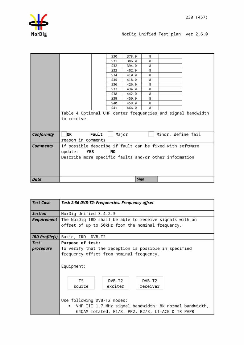
230 (457)
NorDig Unified Test plan, ver 2.6.0
Conformity OK Fault Major Minor, define fail reason in commentsComments If possible describe if fault can be fixed with software update: YES NO
Describe more specific faults and/or other information
Date Sign
Test Case Task 3:67 DVB-T2: Performance: C/(N+I) Performance in SFN for more than one echo
Section NorDig Unified 3.4.10.11Requirement For the DVB-T2 modes shown in (1), the required C/N value for profile 2 (specified in
(1)) for QEF reception shall be obtained when the channel contains two static paths with relative delay from 1.95µs up to 0.95 times guard interval length, independently of the relative amplitudes and phases of the two paths. For 1.7 MHz these DVB-T2 modes apply as well, except that the FFT size is 8K
For a specific echo attenuation the required C/N shall have approximately the same value, independent of the actual delay length. The deviation in required C/N from the median value shall be less than 1 dB, for any echo length from 1.95 µs up to 0.95 times guard interval length.
IRD Profile(s) Basic, IRD, DVB-T2Test procedure Purpose of test:
To verify the SFN synchronization of the receiver when two echo signals are present.
1.7 MHz DVB-T2 modes not tested.
Equipment:
The 0 degree at channel center shall be used in fading simulator (see 2.3.5).
Use Mode A (Single PLP) parameter settings defined in 2.3.7Summary of DVB-T2 modes in DVB-T2 test tasks.
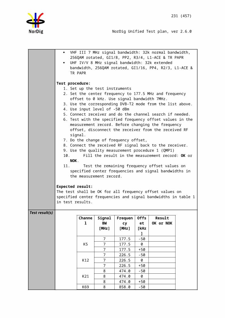
231 (457)
NorDig Unified Test plan, ver 2.6.0
1.7MHz signal BW DVB-T2 modes are tested on 206.352MHz (9C)7MHz signal BW DVB-T2 modes are tested on 198.5MHz (K8)8MHz signal BW DVB-T2 modes are tested on 666MHz (K45),
Test procedure:
Check the different SFN synchronisation issues from 2.3.4 Receiver operability in SFN.
1. Set up the test instruments.2. Use the following DVB-T2 mode 32K extended, 256QAM, PP4, R=2/3,
/TU=1/16 and signal bandwidth 8MHz and center frequency 666MHz (K45).3. Open the switch.4. Conifigure one path of the channel simulator to have a 0dB attenuation, 0µs
delay and 0 degree phase.5. Configure the second path of the channel simulator to have relative delay
difference –100.1µs and attenuation 21dB (pre echo) and 0 degree phase.6. Configure the third path of the channel simulator to have relative delay
difference +100.0µs and attenuation 15 dB (post echo) and 0 degree phase. 7. Set the receiver input level to -50 dBm.8. Close the switch.9. Increase the required C/N value from low value to higher value until the quality
measurement procedure 2 (QMP2) is fulfilled.10. Fill in the required C/N value in dB in the measurement record. 11. Measure the rest of the required C/N values starting at the bottom of the table
and upward. 12. Fill in the results in the measurement record. During the change of the delay
and the attenuation, the input RF signal to receiver shall be disconnected. 13. Repeat the test for the rest of the DVB-T2 modes.
Expected result:The IRD shall synchronize in all combinations defined in measurement record and the required C/N value shall not exceed the required C/N defined for profile 2: 0dB echo in table 2.43 (PP2) and table 2.54 (PP4).
Test result(s) Measurement record:
32k extended 256QAM PP4 R=2/3 /TU=1/16, 8MHz, f=666MHz
Main path Pre echo Post echo C/N [dB]Att
[dB]Delay [us]
Att [dB]
Delay [us]
Att [dB]
Delay [us]
0 0 0 -100.1 0 1000 0 3 -100.1 3 1000 0 6 -100.1 6 1000 0 9 -100.1 9 1000 0 12 -100.1 12 1000 0 15 -100.1 15 1000 0 18 -100.1 18 1000 0 21 -100.1 21 1000 0 15 -100.1 0 100
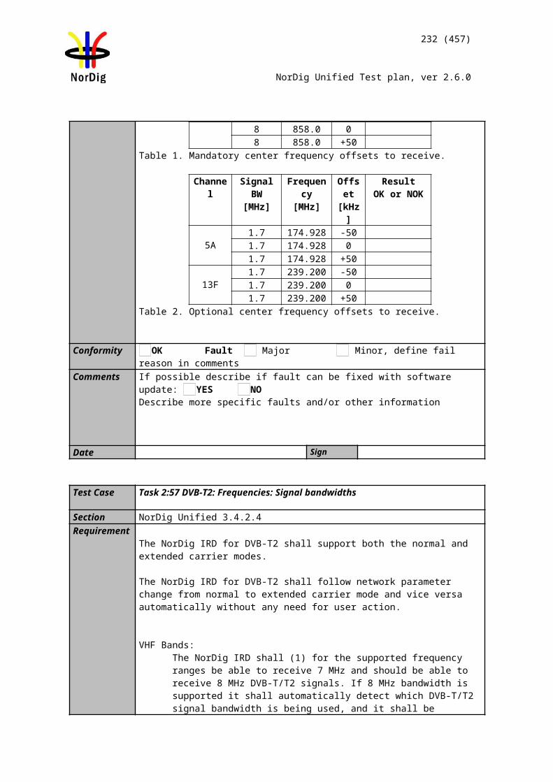
232 (457)
NorDig Unified Test plan, ver 2.6.0
0 0 15 -100.1 3 1000 0 15 -100.1 6 1000 0 15 -100.1 9 1000 0 15 -100.1 12 1000 0 15 -100.1 18 1000 0 15 -100.1 21 1000 0 0 -100.1 15 1000 0 3 -100.1 15 1000 0 6 -100.1 15 1000 0 9 -100.1 15 1000 0 12 -100.1 15 1000 0 18 -100.1 15 1000 0 21 -100.1 15 100
32k extended 256QAM PP4 R=3/5 /TU=19/256, 8MHz,
f=666MHzMain path Pre echo Post echo C/N [dB]
Att [dB]
Delay [us]
Att [dB]
Delay [us]
Att [dB]
Delay [us]
0 0 0 -120.1 0 +120.00 0 3 -120.1 3 +120.00 0 6 -120.1 6 +120.00 0 9 -120.1 9 +120.00 0 12 -120.1 12 +120.00 0 15 -120.1 15 +120.00 0 18 -120.1 18 +120.00 0 21 -120.1 21 +120.00 0 15 -120.1 0 +120.00 0 15 -120.1 3 +120.00 0 15 -120.1 6 +120.00 0 15 -120.1 9 +120.00 0 15 -120.1 12 +120.00 0 15 -120.1 18 +120.00 0 15 -120.1 21 +120.00 0 0 -120.1 15 +120.00 0 3 -120.1 15 +120.00 0 6 -120.1 15 +120.00 0 9 -120.1 15 +120.00 0 12 -120.1 15 +120.00 0 15 -120.1 15 +120.00 0 18 -120.1 15 +120.00 0 21 -120.1 15 +120.0
233 (457)
NorDig Unified Test plan, ver 2.6.0
32k normal 256QAM PP2 R=2/3 /TU=1/8, 7MHz, f=198.5MHz
Main path Pre echo Post echo C/N [dB]Att
[dB]Delay [us]
Att [dB]
Delay [us]
Att [dB]
Delay [us]
0 0 0 -243.1 0 +243.00 0 3 -243.1 3 +243.00 0 6 -243.1 6 +243.00 0 9 -243.1 9 +243.00 0 12 -243.1 12 +243.00 0 15 -243.1 15 +243.00 0 18 -243.1 18 +243.00 0 21 -243.1 21 +243.00 0 15 -243.1 0 +243.00 0 15 -243.1 3 +243.00 0 15 -243.1 6 +243.00 0 15 -243.1 9 +243.00 0 15 -243.1 12 +243.00 0 15 -243.1 18 +243.00 0 15 -243.1 21 +243.00 0 0 -243.1 15 +243.00 0 3 -243.1 15 +243.00 0 6 -243.1 15 +243.00 0 9 -243.1 15 +243.00 0 12 -243.1 15 +243.00 0 15 -243.1 15 +243.00 0 18 -243.1 15 +243.00 0 21 -243.1 15 +243.0
Conformity OK Fault Major Minor, define fail reason in commentsComments If possible describe if fault can be fixed with software update: YES NO
Describe more specific faults and/or other information
Date Sign
Test Case Task 3:68 DVB-T2: Performance: C/(N+I) Performance in SFN inside the guard interval
Section NorDig Unified 3.4.10.11Requirement For the DVB-T2 modes shown in (1), the required C/N value for profile 2 (specified in
(1)) for QEF reception shall be obtained when the channel contains two static paths with relative delay from 1.95µs up to 0.95 times guard interval length, independently of the
234 (457)
NorDig Unified Test plan, ver 2.6.0
relative amplitudes and phases of the two paths. For 1.7 MHz these DVB-T2 modes apply as well, except that the FFT size is 8K
For specific echo attenuation, the required C/N shall not be more than 1 dB higher compared to the median value when calculated for the required C/N values over the echo delays from 1.95 μs up to 0.95 times guard interval length.
IRD Profile(s) Basic, IRD, DVB-T2Test procedure Purpose of test:
To verify the required C/N for echoes in SFN inside the guard interval. Equipment:
Common DVB-T2 parameters in this test task:
Constellation rotation YesPAPR L1-ACE & TR PAPRSISO/MISO SISOFEC Frame length 64800
Input mode Mode ATFS No
Mode HEM
(high efficiency mode)
FEF Not usedAuxiliary streams Not used
The 0 degree channel center shall be used in fading simulator (see 2.3.5).
Test procedure for required C/N in SFN for echoes inside guard interval:
Check the different SFN synchronisation issues from 2.3.4 Receiver operability in SFN.
1. Set up the test instruments.2. Use the following DVB-T2 mode {32K extended, 256QAM, PP4, R=2/3,
/TU=1/16} and signal bandwidth 8MHz.3. Set the up-converter to center frequency 666MHz (K45).4. Open the switch.5. Set the receiver input level to -50 dBm for the wanted signal.
235 (457)
NorDig Unified Test plan, ver 2.6.0
6. Set the channel simulator relative delay difference to 1.95 us for the echo signal.
7. Set the channel simulator relative attenuation level to 0 dB for the echo signal. 8. Set C/N to such a ratio that receiver is unlocked state and reception is not
possible.9. Close the switch.10. Increase the C/N value until the quality measurement procedure 2 (QMP2) is
fulfilled.11. Fill in the required C/N value in dB in the measurement record. 12. Measure the rest of the required C/N values for the negative and positive 0dB
echoes. Fill in the results in the measurement record. During the change of the delay the input RF signal shall be disconnected.
13. Test the rest of the combinations (not marked grey) of the relative delays and attenuation levels. The delay of the echo is maintained constant when the change of the attenuation from 21dB to 1dB is done. Find the required C/N value when the reception still fulfils the quality measurement procedure 2 (QMP2). During the change of the delay and attenuation level the input RF signal shall be disconnected.
14. Continue test from step 4 by repeating the test for the rest of the DVB-T2 modes and signal bandwidth 8MHz in measurement record.
15. Set the up-converter to center frequency 198.5MHz (K8).16. Continue test from step 4 by repeating the test for the rest of the DVB-T2
modes and signal bandwidth 7MHz in measurement record.
Expected result:The IRD shall synchronize in all echo attenuation and delay combinations except the longest values according to below:
32K extended, 256QAM, PP4, R=2/3, /TU=1/16, 8MHz: -220µs and 220µs32K extended, 256QAM, PP4, R=3/5, /TU =19/256, 8MHz: -266µs and 266µs 32K extended, 256QAM, PP2, R=3/4, /TU=1/8, 8MHz: -448µs and 448µs32K normal, 256QAM, PP4, R=2/3, /TU =19/256, 7MHz: -304µs and +304µs32K normal, 256QAM, PP2, R=3/4, /TU =1/8, 7MHz: -500µs and +500µs
The required C/N value for 0dB echo shall not be higher than defined in table 2.43 (PP2) and table 2.54 (PP4).The required C/N for a specific echo amplitude shall not be more than 1 dB higher compared to the median value when calculated for the required C/N values over the echo lengths from 1.95µs up to 0.95 times guard interval length.
Test result(s) Measurement record:
32k extended 256QAM PP4 R=2/3 /TU=1/16, 8MHzdB/us
1.95 10 28 56 90 112.1 130 150 170 190 212 220
0123456789101112
236 (457)
NorDig Unified Test plan, ver 2.6.0
131415161718192021
dB/us
-1.95 -10 -28 -56 -90 -112.1 -130 -150 -170 -190 -212 -220
012345678910111213141516
2.3.10 17
18192021
32k extended 256QAM PP4 R=3/5 /TU=19/256, 8MHzdB/us
1.95 10 25 33 50 66 133 150 170 190 253 266
0123456789101112131415161718192021
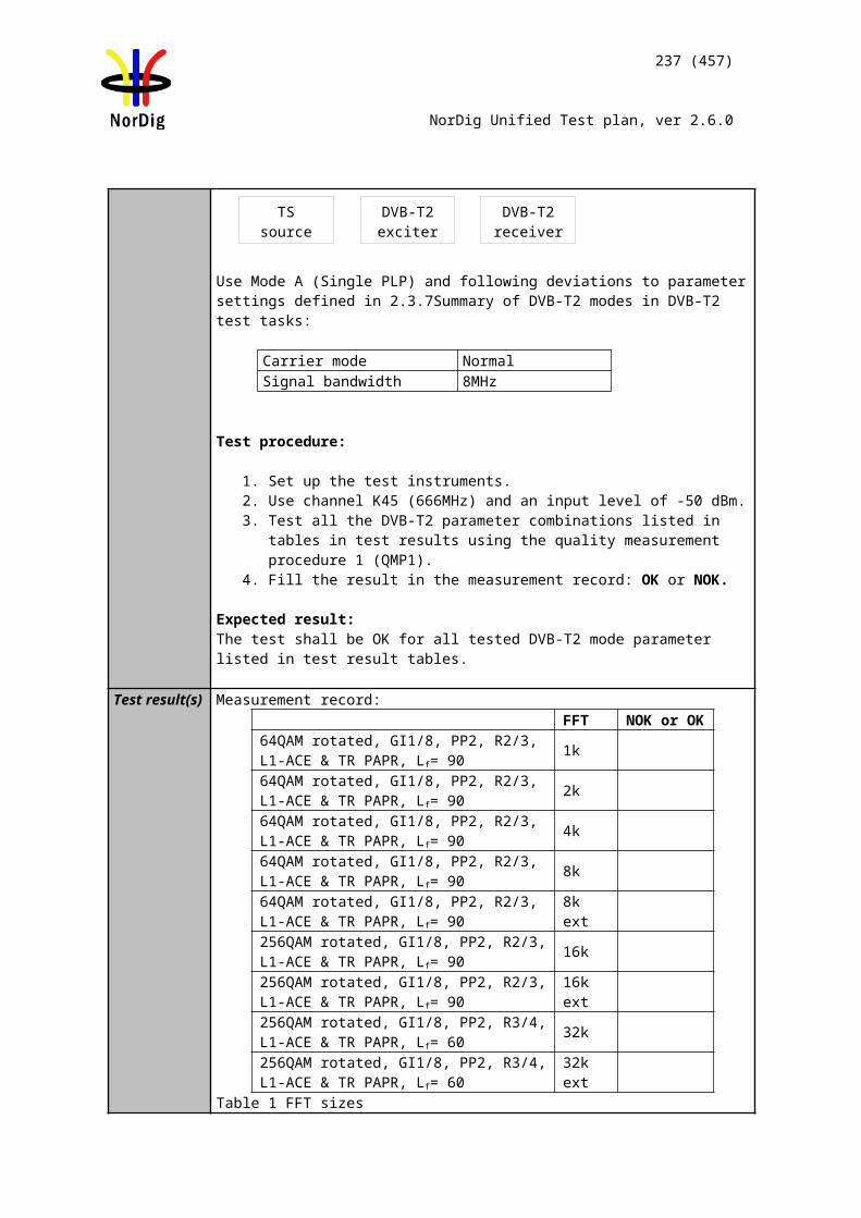
237 (457)
NorDig Unified Test plan, ver 2.6.0
dB/us
-1.95 -10 -25 -33 -50 -66 -133 -150 -170 -190 -253 -266
012345678910111213141516
17
18192021
32k extended 256QAM PP2 R=3/4 /TU=1/8, 8MHzdB/us
1.95 10 28 56 70 112 224 320 384 400 426 448
0123456789101112131415161718192021
dB/us
-1.95 -10 -28 -56 -70 -112 -224 -320 -384 -400 -426 -448
01234567
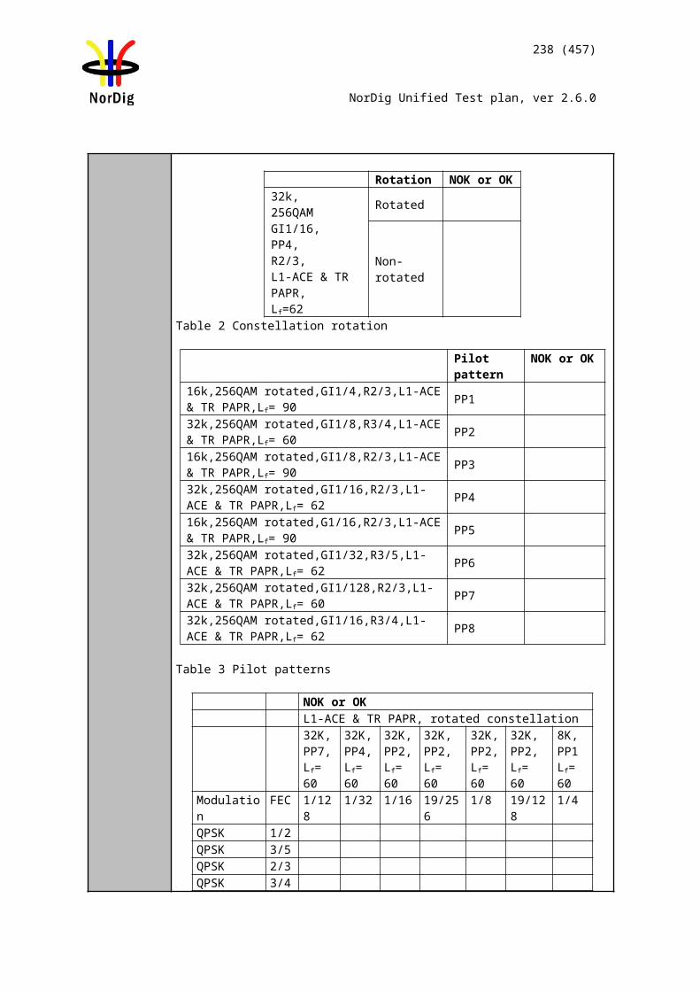
238 (457)
NorDig Unified Test plan, ver 2.6.0
8910111213141516
17
18192021
32K normal, 256QAM, PP4, R=2/3, /TU =19/256, 7MHzdB/us
1.95 10 28 76 128 152 256 289 304
0123456789101112131415161718192021
dB/us
-1.95 -10 -28 -76 -128 -152 -256 -289 -304
012345678910111213141516171819
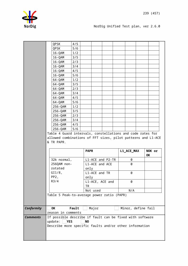
239 (457)
NorDig Unified Test plan, ver 2.6.0
2021
32K normal, 256QAM, PP2, R=3/4, /TU=1/8, 7MHzdB/us
1.95 10 28 56 128 170 256 320 384 416 486 500
0123456789101112131415161718192021
dB/us
-1.95 -10 -28 -56 -128 -170 -256 -320 -384 --416 -486 -500
0123456789101112131415161718192021
Conformity OK Fault Major Minor, define fail reason in commentsComments If possible describe if fault can be fixed with software update: YES NO
Describe more specific faults and/or other information
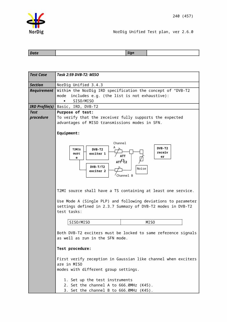
240 (457)
NorDig Unified Test plan, ver 2.6.0
Date Sign
Test Case Task 3:69 DVB-T2: Performance: C/(N+I) Performance in SFN outside the guard interval
Section NorDig Unified 3.4.10.11Requirement For echoes outside the guard interval, for 8 MHz DVB-T2 signal, QEF reception shall
be possible with echo levels up to the values defined in Table 3.224.
For echoes outside the guard interval, for 7 MHz DVB-T2 signal, QEF reception shall be possible with echo levels up to the values defined in Table 3.235.
IRD Profile(s) Basic, IRD, DVB-T2Test procedure Purpose of test:
To verify the SFN synchronisation in SFN for echoes outside guard interval.
Equipment:
Common DVB-T2 parameters in this test task:
Constellation rotation YesPAPR L1-ACE & TR PAPRSISO/MISO SISOFEC Frame length 64800
Input mode Mode ATFS No
Mode HEM
(high efficiency mode)
FEF Not usedAuxiliary streams Not used
Test procedure for evaluation of synchronization for echoes outside the guard interval:
Check the different SFN synchronisation issues from 2.3.4 Receiver operability in SFN.
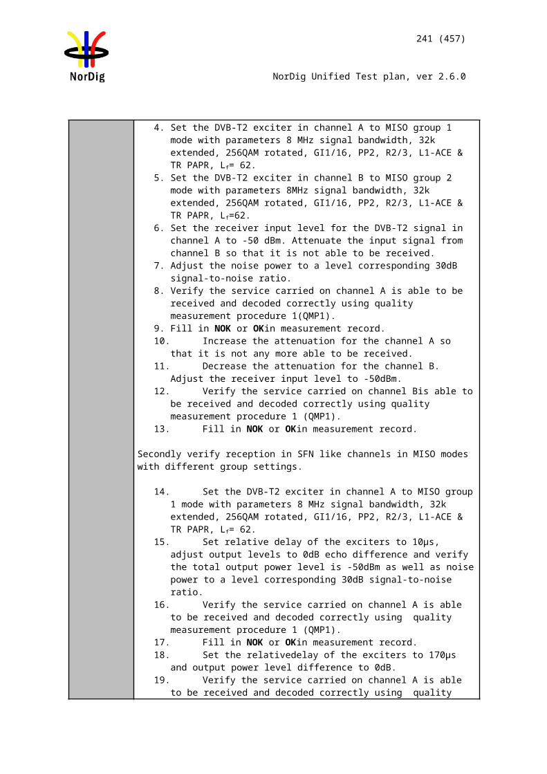
241 (457)
NorDig Unified Test plan, ver 2.6.0
1. Set up the test instruments.2. Use the following mode {32K, 256QAM, PP4, R=3/5, /TU=1/16} and signal
bandwidth 8MHz.3. Open the switch.4. Set the receiver input level to -50 dBm for the wanted signal.5. Set the channel simulator relative delay difference to 260µs for the echo signal.6. Close the switch.7. Increase the echo attenuation from low value to higher value until quality
measurement procedure 2 (QMP2) is fulfilled.8. Fill in echo attenuation result in dB in the measurement record. 9. Repeat the test the rest of the combinations of the relative delays and
attenuation levels defined in measurement record.. Open the switch before changing the delay and attenuation level.
10. Repeat the test for the rest of the DVB-T2 modes in the measurement record for the signal bandwidth 8MHz.
11. Set the up-converter to center frequency 198.5MHz (K8).12. Follow the test procedure and repeat the test for the 7 MHz signal bandwidth
and DVB-T2 modes defined in the measurement record according to procedure above.
Expected result:All the echo attenuation values shall be equal or lower compared to NorDig Unified values in tables 3.22 and 3.23.
Test result(s) Measurement record:
7 MHz signal bandwidthDVB-T2 mode Echo delay [µs]
-298 -266 -215 -165 -13532K nor, 256-QAM, PP4, R=3/5, GI=1/1632K nor, 256-QAM, PP4, R=2/3, GI =1/1632K nor, 256-QAM, PP4, R=3/4, GI =1/1632K nor, 256-QAM, PP4, R=3/5, GI =1/3232K nor, 256-QAM, PP4, R=2/3, GI =1/3232K nor, 256-QAM, PP4, R=3/4, GI =1/32
Echo delay [µs]298 266 215 165 135
32K nor, 256-QAM, PP4, R=3/5, GI =1/1632K nor, 256-QAM, PP4, R=2/3, GI =1/1632K nor, 256-QAM, PP4, R=3/4, GI =1/1632K nor, 256-QAM, PP4, R=3/5, GI =1/3232K nor, 256-QAM, PP4, R=2/3, GI =1/3232K nor, 256-QAM, PP4, R=3/4, GI =1/32
7 MHz signal bandwidthDVB-T2 mode Echo delay [µs]
-608 -512 -400 -298 -26632K nor, 256-QAM, PP2, R=3/5, GI=1/1632K nor, 256-QAM, PP2, R=2/3, GI =1/1632K nor, 256-QAM, PP2, R=3/4, GI =1/16
Echo delay [µs]608 512 400 298 266
32K nor, 256-QAM, PP2, R=3/5, GI =1/1632K nor, 256-QAM, PP2, R=2/3, GI =1/16
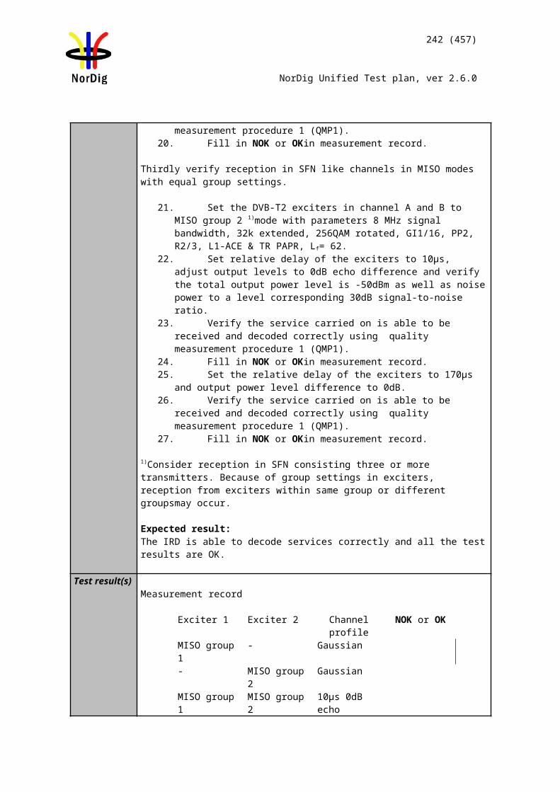
242 (457)
NorDig Unified Test plan, ver 2.6.0
32K nor, 256-QAM, PP2, R=3/4, GI =1/16
8 MHz signal bandwidthDVB-T2 mode Echo delay [µs]
-260 -230 -200 -150 -12032K ext, 256-QAM, PP4, R=3/5, GI =1/1632K ext, 256-QAM, PP4, R=2/3, GI =1/1632K ext, 256-QAM, PP4, R=3/4, GI =1/1632K ext, 256-QAM, PP4, R=3/5, GI =1/3232K ext, 256-QAM, PP4, R=2/3, GI =1/3232K ext, 256-QAM, PP4, R=3/4, GI =1/32
Echo delay [µs]260 230 200 150 120
32K ext, 256-QAM, PP4, R=3/5, GI =1/1632K ext, 256-QAM, PP4, R=2/3, GI =1/1632K ext, 256-QAM, PP4, R=3/4, GI =1/1632K ext, 256-QAM, PP4, R=3/5, GI =1/3232K ext, 256-QAM, PP4, R=2/3, GI =1/3232K ext, 256-QAM, PP4, R=3/4, GI =1/32
Conformity OK Fault Major Minor, define fail reason in commentsComments If possible describe if fault can be fixed with software update: YES NO
Describe more specific faults and/or other information
Date Sign
2.4 Task 4: IP-Based Front-end
- Not yet available-
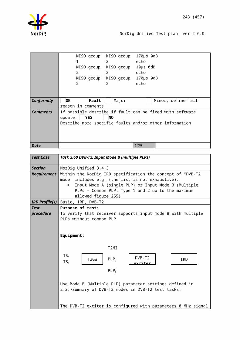
243 (457)
NorDig Unified Test plan, ver 2.6.0
2.5 Task 5: MPEG2 demultiplexerTest Case Task 5:1 SI utilization
Section NorDig Unified 4.1RequirementIRD Profile(s) Basic, IRD, FETest procedure
Utilization of MPEG-2 Service Information shall be tested under Task 8.
Test Case Task 5:2 CA descriptor interpretation
Section NorDig Unified 4.1Requirement The NorDig IRD shall interpret the CA descriptor as defined in ETR 289IRD Profile(s) Basic, IRD, FETest procedure
This test is covered with tests Task 11:24, Task 10:1 and Task 10:2
Test Case Task 5:3 Maximum transport stream data rate
Section NorDig Unified 4.1 and 3Requirement The NorDig IRD shall be able to decode an ISO/IEC 13818-1 stream with data rates up
to that include all rates that the front-end may deliver as defined in NorDig Unified chapter 3.Note: The satellite front-end may deliver up to 80.4 Mbps after error correction
IRD Profile(s) Basic, IRD, FETest procedure Purpose of test:
Purpose of the test is to verify that IRD supports maximum transport stream data rate.
Equipment:
Terrestrial front-end (DVB-T) only:Test multiplex with the maximum bitrate of 31.67 Mbit/s and carrying one or more services with video/audio content and teletext components.
Satellite front-ends only:Test multiplex with the maximum bitrate of 72 Mbit/s and carrying one or more services with video/audio content and teletext components.
Cable front-ends only:Test multiplex with the maximum bitrate of 53,45 Mbit/s and carrying one or more services with video/audio content and teletext components.IP-front-end only:TBD
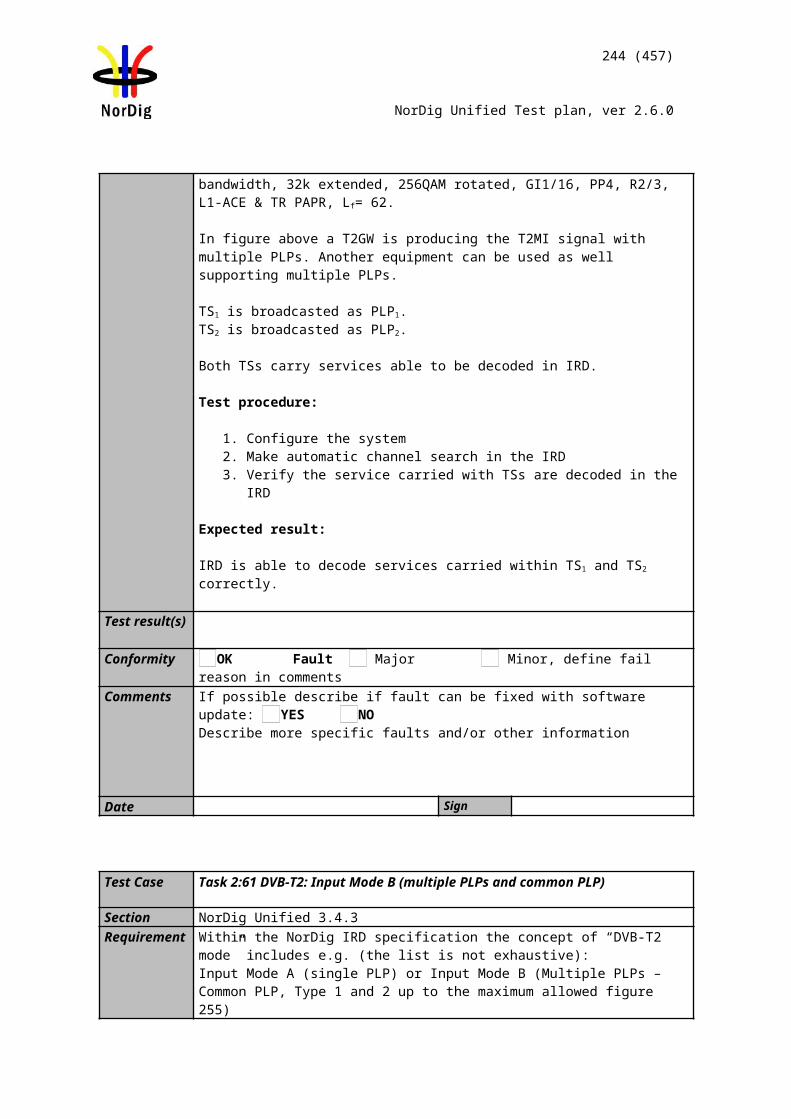
244 (457)
NorDig Unified Test plan, ver 2.6.0
Test procedure: This is general requirement that will be test in front-end tests.
Expected result:
Test result(s)Conformity OK Fault Major Minor, define fail reason in commentsComments If possible describe if fault can be fixed with software update: YES NO
Describe more specific faults and/or other information
Date Sign
Test Case Task 5:4 Number of elementary streams
Section NorDig Unified 4.1Requirement The NorDig IRD shall be capable to utilise at least 32 elementary streams
simultaneously, which requires 32 PID filters.IRD Profile(s) Basic, IRD, FETest procedure Purpose of test:
To verify IRD’s capability to utilize at least 32 elementary streams simultaneously.
Equipment:The manufacturer describes his specific set-up for the test
Test procedure:Due to the complexity to test the ability to handle 32 elementary streams simultaneously, this test can be difficult to fully test.
Instead the supplier shall ensure that this requirement is met.
If no such statement of conformance is issued, a test containing the maximum number of components used in the broadcast network should be performed. At least following amount and types of components shall be tested within a service:
Audio MPEG1 LII audio AC-3, video, EBU teletext DVB subtitling Data, e.g. DSMCC data craousel.
In the future up to three PID’s for data applications could be included.
Note: The number simultaneously elementary streams used in the test shall be stated in the comments below.
Test result(s)Conformity OK Fault Major Minor, define fail reason in commentsComments If possible describe if fault can be fixed with software update: YES NO
Describe more specific faults and/or other information
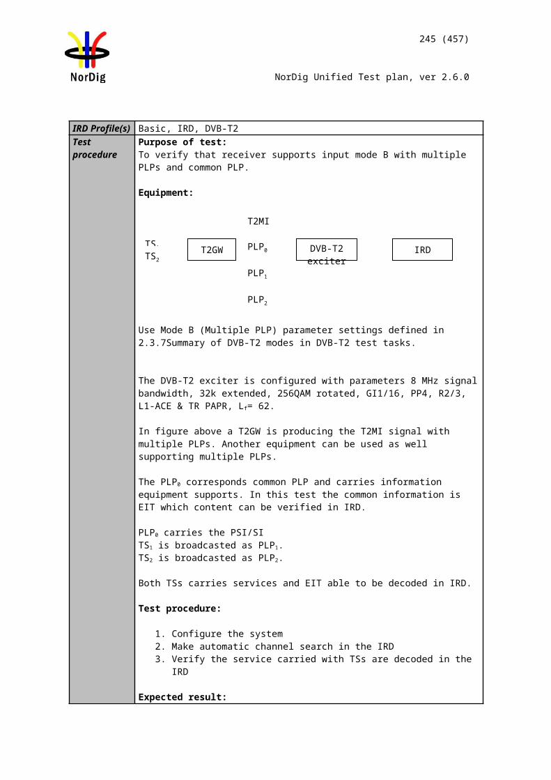
245 (457)
NorDig Unified Test plan, ver 2.6.0
Date Sign
Test Case Task 5:5 Section filtering
Section NorDig Unified 4.1Requirement The NorDig IRD shall provide at least 32 section filters. IRD Profile(s) Basic, IRD, FETest procedure Purpose of test:
To verify IRD’s capability to utilize at least 32 sections.
Equipment:The manufacturer describes his specific set-up for the test
Test procedure:
The stream_type 0x05 corresponds private sections. One section is 4096 bytes. Therefore, the requirement is up 32 * 4096 bytes.
All PSI/SI data transmitted in sections. Therefore, the requirement of amount PSI/SI sections to handle is 32 * 4096 bytes.
Expected result:The supplier shall ensure that this requirement is met.
Test result(s)Conformity OK Fault Major Minor, define fail reason in commentsComments If possible describe if fault can be fixed with software update: YES NO
Describe more specific faults and/or other information
Date Sign
Test Case Task 5:6 Variable Bitrate Elementary Streams
Section NorDig Unified 4.1Requirement The NorDig IRD shall support variable bitrate elementary streams within a constant
bitrate transport stream (excluding audio).IRD Profile(s) Basic, IRD, FE
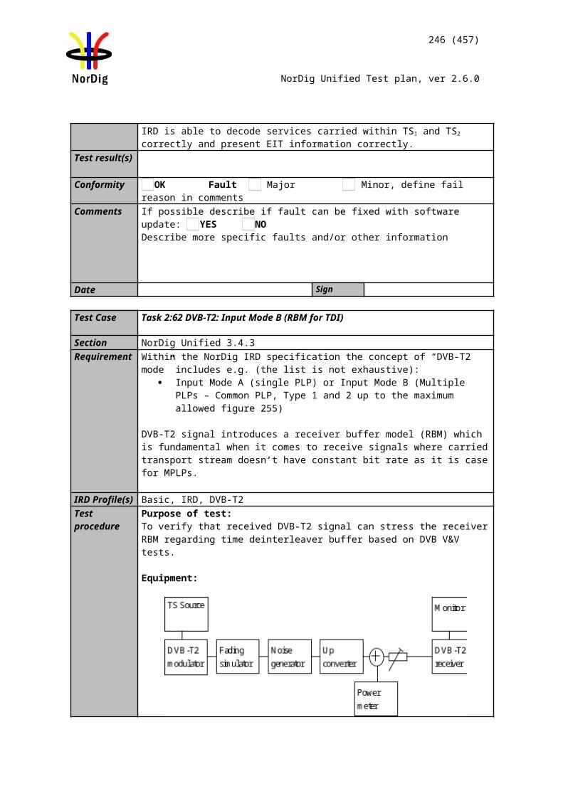
246 (457)
NorDig Unified Test plan, ver 2.6.0
Test procedure Purpose of test:To verify that the IRD can decode a variable bitrate video stream (statistical multiplexing).
Test Equipment:Test signals are created using the test bed shown below:
Test signal configuration:
The bitrate variation range in test streams shall be e.g.:- 6 – 11 Mbit/s- 2 – 6 Mbit/s- 2 – 6 Mbit/s- 3 – 11 Mbit/s
Test procedure:The IRD is tuned to a Transport Stream that contains variable bitrate Elementary Streams (statistical multiplexing of video).No noise addedIRD input level: -60 dBmRGB pictures displayed on a monitor is observed.
Expected result: The IRD is capable of displaying an error-free picture during 5 minutes. The audio and video shall be muted during acquisition.
Test result(s)Conformity OK Fault Major Minor, define fail reason in commentsComments If possible describe if fault can be fixed with software update: YES NO
Describe more specific faults and/or other information
Date Sign
Test Case Task 5:7 Mixture of SD and HD services
Section NorDig Unified 4.1Requirement The NorDig HDTV IRD shall support a mixture of service types within the same
ISO/IEC 13818-1[42] MPEG-2 transport stream (i.e. MPEG-2 SDTV service, MPEG-4 AVC SDTV and HDTV and Radio services may be multiplexed into the same transport stream).
IRD Profile(s) Basic, IRD, FE
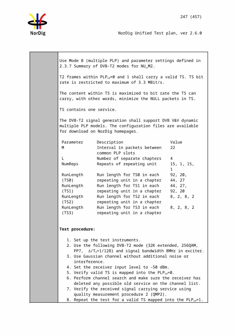
247 (457)
NorDig Unified Test plan, ver 2.6.0
Test procedure Purpose of test:To verify the receiver is able to decode mixture of SD and HD services.
Equipment:
Transport stream(s) containing: Digital tv SD service (0x01) with
o MPEG-2 720x576i 25Hz video component o MPEG-1 Layer II audio component
Advanced codec SD digital tv service (0x16) with o MPEG-4 AVC 720x576i 25Hz video component o MPEG-4 HE.AAC v1 audio component
Advanced codec HD digital tv Service (0x19) with o MPEG-4 AVC 1280x720p 50Hz video componento DD E-AC-3 audio component
Digital radio sound service (0x02) with o MPEG-1 Layer II audio component
Advanced codec digital radio sound service (0x0A) with o MPEG-4 HE.AAC Level 4 audio component.
Advanced codec digital radio sound service (0x0A) with o DD E-AC-3 audio component.
Test procedure:Tune to the services and verify that the service is decoded correctly.
Expected result:NorDig SDTV Level IRD receiver doesn’t install HD services in service list and therefore doesn’t decode HD services. NorDig HDTV Level IRD is able to decode both HD and SD services.
Test result(s)Conformity OK Fault Major Minor, define fail reason in commentsComments If possible describe if fault can be fixed with software update: YES NO
Describe more specific faults and/or other information
Date Sign
Test Case Task 5:8 Descrambler Performance
Section NorDig Unified 4.2Requirement The descrambler unit is based on the common scrambling algorithm as specified by
DVB, see DVB A 011 [5]. Common Scrambling Algorithms versions 2 and 3 shall (1) be implemented in the NorDig IRD. The algorithms are available from ETSI (2). See also section 9. It shall (1) be able to descramble on transport level and on PES format. The NorDig IRD shall (1) be able to process in parallel up to at least 6 different streams (either PES or transport level) with different access conditions. Data streams without ac-cess control shall be bypassed by the descrambling unit.
IRD Profile(s) Basic, IRD, FE
MUX Exciter IRDTS Source
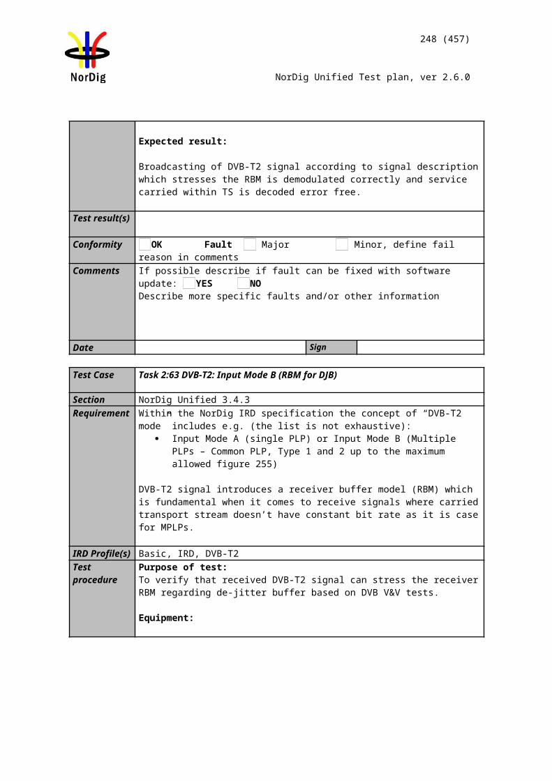
248 (457)
NorDig Unified Test plan, ver 2.6.0
Test procedureThis test is tested in Task 10:
Test Case Task 5:9 System clock recovery
Section NorDig Unified 4.3Requirement During the system time clock (STC) acquisition audio and video shall be muted. (The
transition shall be smooth and seamless when the customer changes the channel). The decoder shall be able to:• recover the STC using PCR with maximum jitter of +/- 10 µs.• track long-term variations in the frequency of the encoder’s STC.For each service, the demultiplexer shall recover the source clock by extracting the associated PCR values received within the incoming multiplex and insert them into the appropriate Phase Locked Loop.
IRD Profile(s) Basic, IRD, FETest procedure Purpose of test:
To verify that the IRD is able to recover system clock with PCR jitter amplitudes of +- 10 s.
Test Equipment:Test signals are created using the test bed shown below:
A transport stream including services with following components: Service 1
o MPEG4 AVC HP@L3 576i 25Hz video PID with rapid variations of the PCR values
o MPEG4 HE AAC L2 audio PID Service 2
o MPEG4 AVC HP@L3 576i 25Hz video PID with longterm variations of the PCR values
o MPEG4 HE AAC L2 audio PID Service 3
o MPEG2 MP@ML 576i 25Hz video PID with rapid variations of the PCR values
o MPEG1 LII audio PID Service 4
o MPEG2 MP@ML 576i 25Hz video PID with longterm variations of the PCR values
o MPEG1 LII audio PID
Characteristics of the PCR variations are defined below.
Rapid variation PCR(sawtooth wave)
MUX Exciter IRDTS Source
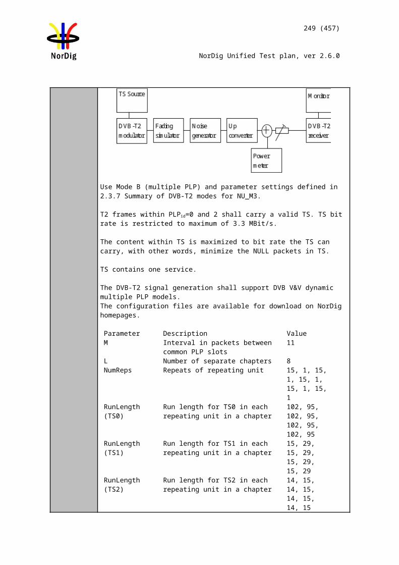
±10µs
7 seconds
±500ns
10 seconds
249 (457)
NorDig Unified Test plan, ver 2.6.0
Long term variation PCR (constant sine wave)
Test procedure:
1. Set IRD input level to -60 dBm2. Play out the TS3. Do the channel search if required4. Verify that IRD provides error free video and there is no irritating lipsync.
Expected result: The NorDig IRD is capable of displaying an error-free picture during 5 minutes. The audio and video shall be in synchronization, with other words, there is no irritating lipsync.
Test result(s)Conformity OK Fault Major Minor, define fail reason in commentsComments If possible describe if fault can be fixed with software update: YES NO
Describe more specific faults and/or other information
Date Sign
2.6 Task 6: Video
Test Case Task 6:1 Video Decoder - General
Section NorDig Unified 5.1Requirement The NorDig IRD’s video decoder shall fully comply with the DVB Implementation
Guidelines for the use of MPEG-2 SDTV and H.264/AVC SDTV and HDTV video in
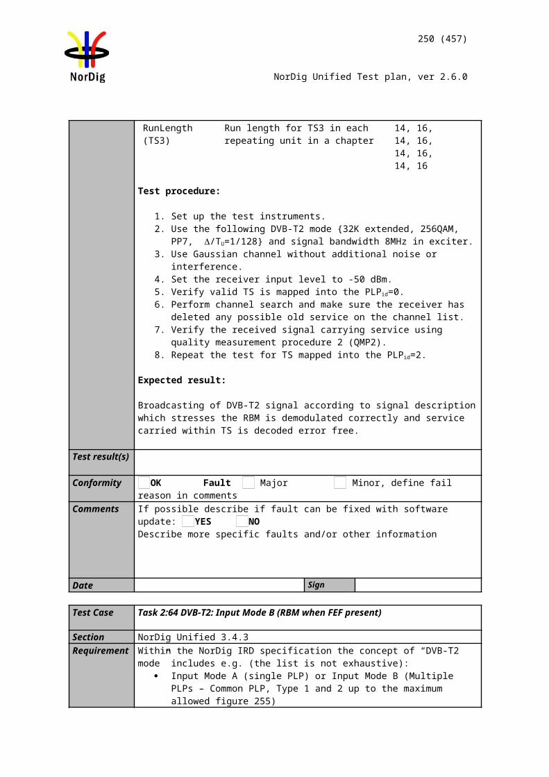
TS Source MUX Exciter IRD
250 (457)
NorDig Unified Test plan, ver 2.6.0
satellite, cable and terrestrial broadcasting applications, ETSI TS 101 154 [29].
The following clauses of ETSI TS 101 154 [29] are relevant to this specification:
• 5.1; 25Hz MPEG-2 SDTV IRDs and Bitstreams
• 5.5; Specifications Common to all H.264/AVC IRDs and Bitstreams
• 5.6; H.264/AVC SDTV IRDs and Bitstreams. The minimum profile requirements for Nordig ID for SDTV content is High Profile at Level 3.0
• 5.7.1 and 5.7.2; H.264/AVC HDTV IRDs and Bitstreams, The minimum profile requirements for Nordig ID for HDTV content is High Profile at Level 4.0
IRD Profile(s) Basic, IRD, FETest procedure
This is a general requirement. It will be verified in the following tests
Date Sign
Test Case Task 6:2 Video Decoder – Resolutions and Frame rates
Section NorDig Unified 5.2Requirement The Video Decoder shall (1) be able to receive and decode the video formats specified
in Table 5.1.
IRD Profile(s) Basic, IRD, FETest procedure Purpose of test:
To verify that all video luminance resolutions and frame rates are displayed correctly.
Equipment:
Source must have TS containing all the video formats listed in test results.
Test procedure:
1. Play streams that contain all video formats in measurement record table below 2. Tune to services3. Verify that the services are decoded and displayed correctly4. Fill in test results
Expected result:
Verify that the video is decoded and displayed correctly.
Test result(s)Measurement record:
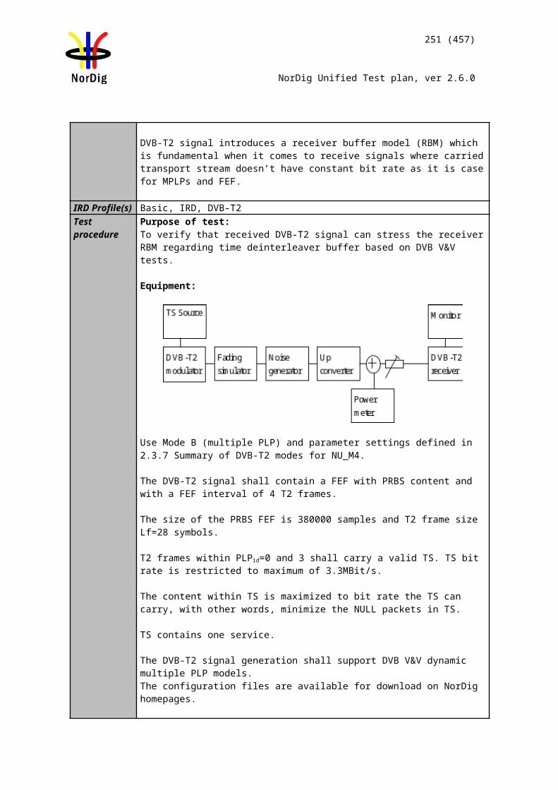
251 (457)
NorDig Unified Test plan, ver 2.6.0
Video Luminance ResolutionsHorizontal x Vertical,
Frame rate [Hz]I/P
Frame Aspect Ratio(Horizontal :
Vertical)
Bit Stream(Profile@ Level) OK/
NOK
352x288 25 I 4:3 MPEG-2 MP@ML352x288 25 I 16:9 MPEG-2 MP@ML352x288 25 I 4:3 AVC HP@L3352x288 25 I 16:9 AVC HP@L3352x576 25 I 4:3 MPEG-2 MP@ML352x576 25 I 16:9 MPEG-2 MP@ML352x576 25 I 4:3 AVC HP@L3352x576 25 I 16:9 AVC HP@L3480x576 25 I 4:3 MPEG-2 MP@ML480x576 25 I 16:9 MPEG-2 MP@ML480x576 25 I 4:3 AVC HP@L3480x576 25 I 16:9 AVC HP@L3544x576 25 I 4:3 MPEG-2 MP@ML544x576 25 I 16:9 MPEG-2 MP@ML544x576 25 I 4:3 AVC HP@L3544x576 25 I 16:9 AVC HP@L3720x576 25 I 4:3 MPEG-2 MP@ML720x576 25 I 16:9 MPEG-2 MP@ML720x576 25 I 4:3 AVC HP@L3
720x576 25 I 16:9 AVC HP@L3640x720 50 P 16:9 AVC HP@L4960x720 50 P 16:9 AVC HP@L41280x720 50 P 16:9 AVC HP@L4960x1080 25 I 16:9 AVC HP@L4
960x1080 25 P 16:9 AVC HP@L41280x1080 25 I 16:9 AVC HP@L4
1280x1080 25 P 16:9 AVC HP@L41440x1080 25 I 16:9 AVC HP@L4
1440x1080 25 P 16:9 AVC HP@L4
1920x1080 25 I 16:9 AVC HP@L41920x1080 25 P 16:9 AVC HP@L4
Conformity OK Fault Major Minor, define fail reason in commentsComments If possible describe if fault can be fixed with software update: YES NO
Describe more specific faults and/or other information
Date Sign
Test Case Task 6:3 Up-sampling/Up-conversion
Section NorDig Unified 5.3Requirement When up-converting video with an encoded luminance resolution of 720x576 or
704x576 to any 1:1 pixel aspect ratio format (i.e. 1280x720 or 1920x1080), only the centred 702 of the horizontal 720 / 704 pixels shall be used. Those 702 pixels correspond to the 52 microseconds of an active line, hence preserves correct geometry in
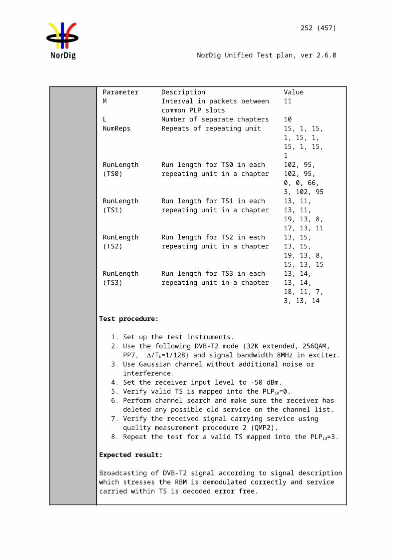
252 (457)
NorDig Unified Test plan, ver 2.6.0
the up-conversion process.
When up-converting other valid input line resolution format to any 1:1 pixel aspect (output) format (i.e. 1280x720 or 1920x1080), only the centred horizontal pixels shall be used; e.g. when up-converting (received) 544x576 line resolution format to any 1:1 pixel aspect ratio (output) format, only the centred 530 pixels of the horizontal 544 shall be used.
IRD Profile(s) Basic, IRD, FETest procedure Purpose of test:
When up-converting valid input line resolution format to any 1:1 pixel aspect (output) format, only the centered horizontal pixels shall be used.
Equipment:
Transport stream containing: 720 x 576 video signal 704x576 video signal 544x576 video signal
Test procedure:
Verify that only the centred horizontal pixels shall be used for up-converting valid input line resolution to 1:1 pixel output (1920x1080, 1280x720). This is 702 horizontal pixels from 720/704x576 material and 530 pixels from 544x576 material.
Expected result: When up-converting video with an encoded luminance resolution to any 1:1 pixel aspect ratio format , only the centred horizontal pixels shall be used. The geometry of the original picture shall be preserved.
Test result(s)Conformity OK Fault Major Minor, define fail reason in commentsComments If possible describe if fault can be fixed with software update: YES NO
Describe more specific faults and/or other information
Date Sign
Test Case Task 6:4 Video Decoder - Colorimetry
Section NorDig Unified 5.4Requirement The Decoder Format Converter shall use the VUI (Video Usability Information)
parameters (ISO/IEC 14496-10)[56] colour_primaries, transfer_characteristics and matrix_coeffecients in received AVC encoded bitstreams and the Sequence Display Extension parameters (ISO/IEC 13818-2) [53] in MPEG-2 encoded bitstreams.The “Decoder Composition Output” shall output video with colour parameters targeting an ideal display, optimised for each video format.
IRD Profile(s) Basic, IRD, FE
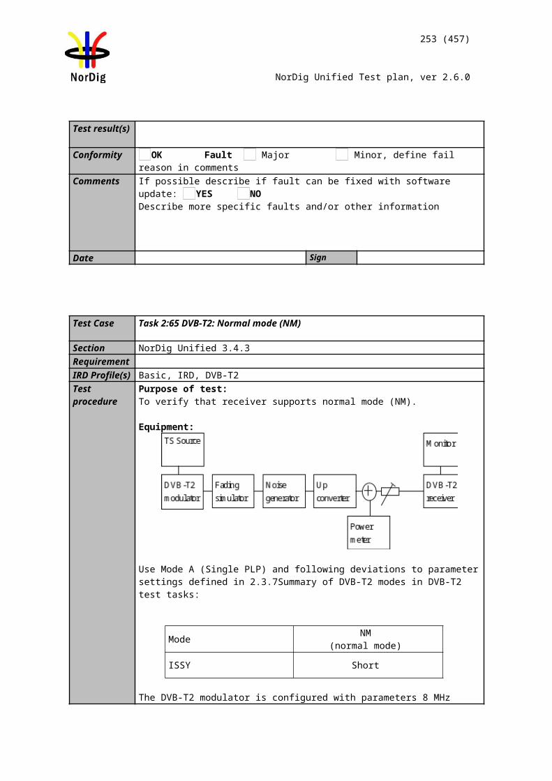
Source MUX Exciter DVB receiver
Monitor
253 (457)
NorDig Unified Test plan, ver 2.6.0
Test procedure Purpose of test:To verify that the IRD is able to output video with colour parameters targeting an ideal display, optimised for each video format.
Equipment:
Test procedure:
TBD
Expected result:The IRD is able to output video with colour parameters targeting an ideal display, optimised for each video format.
Test result(s)
Conformity OK Fault Major Minor, define fail reason in commentsComments If possible describe if fault can be fixed with software update: YES NO
Describe more specific faults and/or other information
Date Sign
Test Case Task 6:5 Video Decoder - Dynamic changes in video stream
Section NorDig Unified 5.5Requirement The NorDig IRD shall be able to handle dynamic changes in transmission between
different video formats and frame rates (e.g 720p50 to 1080i25/1080p25 and 576i25 to 720p50), including changes in encoded sub resolution (e.g. 720x576 to 544x576) within one second after receiving Random Access Point. (Random Access Point equals AVC RAP for H.264/AVC and Sequence header for MPEG-2). The Nordic IRD shall adapt to changes in transmitted aspect ratio (e.g. 16:9 / 4:3) within one second after the reception. The transition shall cause minimal disturbance of the decoded service.
IRD Profile(s) Basic, IRD, FE
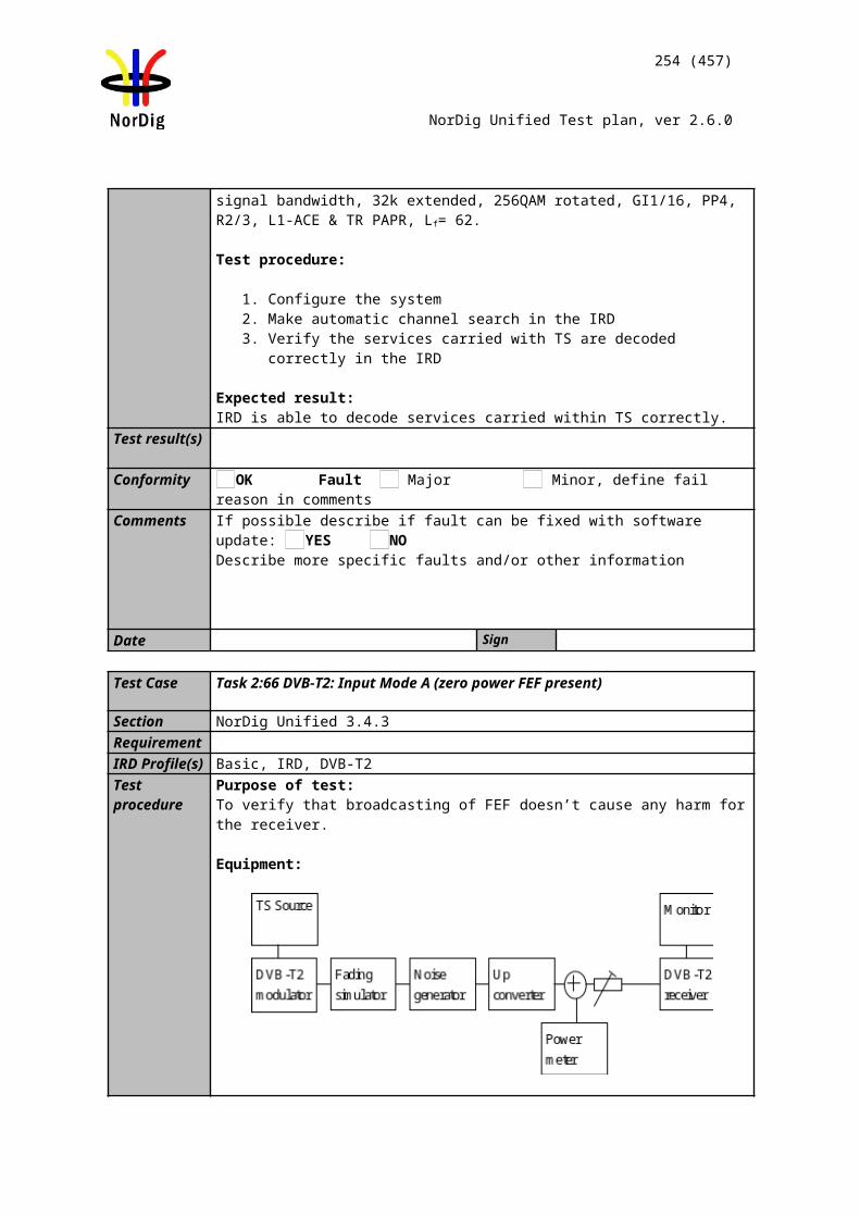
Source MUX Exciter DVB receiver
Monitor
254 (457)
NorDig Unified Test plan, ver 2.6.0
Test procedure Purpose of test:To verify that the receiver is able to handle dynamic changes in transmission between different video modes.
Equipment:
Transport stream containing services with following video content and transitions between them:
MPEG-4 AVC HP@L3 576i 25Hz MPEG-4 AVC HP@L4720p 50Hz MPEG-4 AVC HP@L41080i 25Hz MPEG-2 MP@ML 576i 25Hz
Test procedure:Tune to the service and verify that the transitions between encoding modes are reasonably smooth and that the decoding is resumed after a transition within
Five seconds in case of codec change. One second in case of resolution chance.
..Fill in result to test results table below.
Expected result:The IRD is able to handle mode changes.
Test result(s)From To OK/NOKMPEG-4 AVC HP@L3 576i 25Hz 4:3
MPEG-4 AVC HP@L4720p 50Hz
MPEG-4 AVC HP@L4720p 50Hz
MPEG-4 AVC HP@L3 576i 25Hz 4:3
MPEG-4 AVC HP@L4720p 50Hz
MPEG-4 AVC HP@L41080i 25Hz
MPEG-4 AVC HP@L41080i 25Hz
MPEG-4 AVC HP@L4720p 50Hz
MPEG-4 AVC HP@L41080i 25Hz
MPEG-4 AVC HP@L3 576i 25Hz 4:3
MPEG-4 AVC HP@L3 576i 25Hz 4:3
MPEG-4 AVC HP@L41080i 25Hz
MPEG-2 MP@ML576i 25Hz 4:3
MPEG-4 AVC HP@L4720p 50Hz
MPEG-4 AVC HP@L4720p 50Hz
MPEG-2 MP@ML576i 25Hz 4:3
Conformity OK Fault Major Minor, define fail reason in commentsComments If possible describe if fault can be fixed with software update: YES NO
Describe more specific faults and/or other information
Date Sign
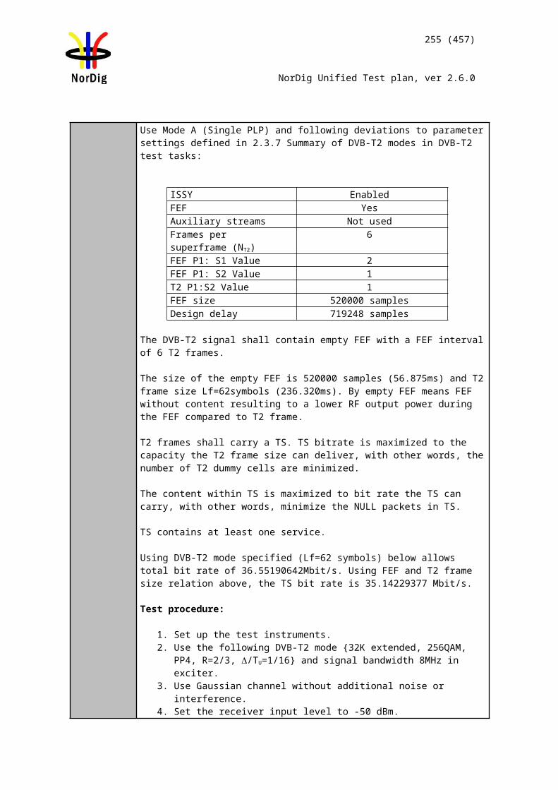
Source MUX Exciter DVB receiver
Monitor
255 (457)
NorDig Unified Test plan, ver 2.6.0
Test Case Task 6:6 Video Decoder - AVC still picture
Section NorDig Unified 5.6Requirement By still picture means broadcast of only intra coded frames at very low frame rate
(typical 1 frame per second). The NorDig IRD shall decode this still picture frame and repeat displaying this until next (still picture) frame is available to display.
The NorDig IRD shall support still picture for the h.264/AVC profiles main and high.
For the signalling of the AVC still picture the AVC video-descriptor will be used (in PMT) as specified in MPEG-2 Systems (ISO/IEC 13818-1 [54] and TS 101154 v1.10.1 [29]. The flag AVC_still_present will be set to 1.
IRD Profile(s) Basic, IRD, FETest procedure Purpose of test:
To verify that the receiver is able to decode AVC still pictures.
Equipment:
Transport stream with AVC still pictures and an IRD. The bitrate of AVC still picture stream is 100 kbit/s.
Use following resolutions in the test stream(s): 720x576 HP@L3 1280x720 HP@L4 1920x1080 HP@L4
According to requirement still pictures are typically broadcasted at 1 frame/s. This can be initially difficult to achieve for given resolutions in bit rates down to 100 kbit/s.
Test procedure:
Tune to the service(s) and verify that the IRD decodes AVC still pictures correctly.
If the 100kbit/s bit rate is not achieved, the tested bit rate shall be noted in comments.
Expected result:
The IRD is able to decode AVC still pictures at the bitrate of 100 kbit/s.
Test result(s)Conformity OK Fault Major Minor, define fail reason in commentsComments If possible describe if fault can be fixed with software update: YES NO
Describe more specific faults and/or other information
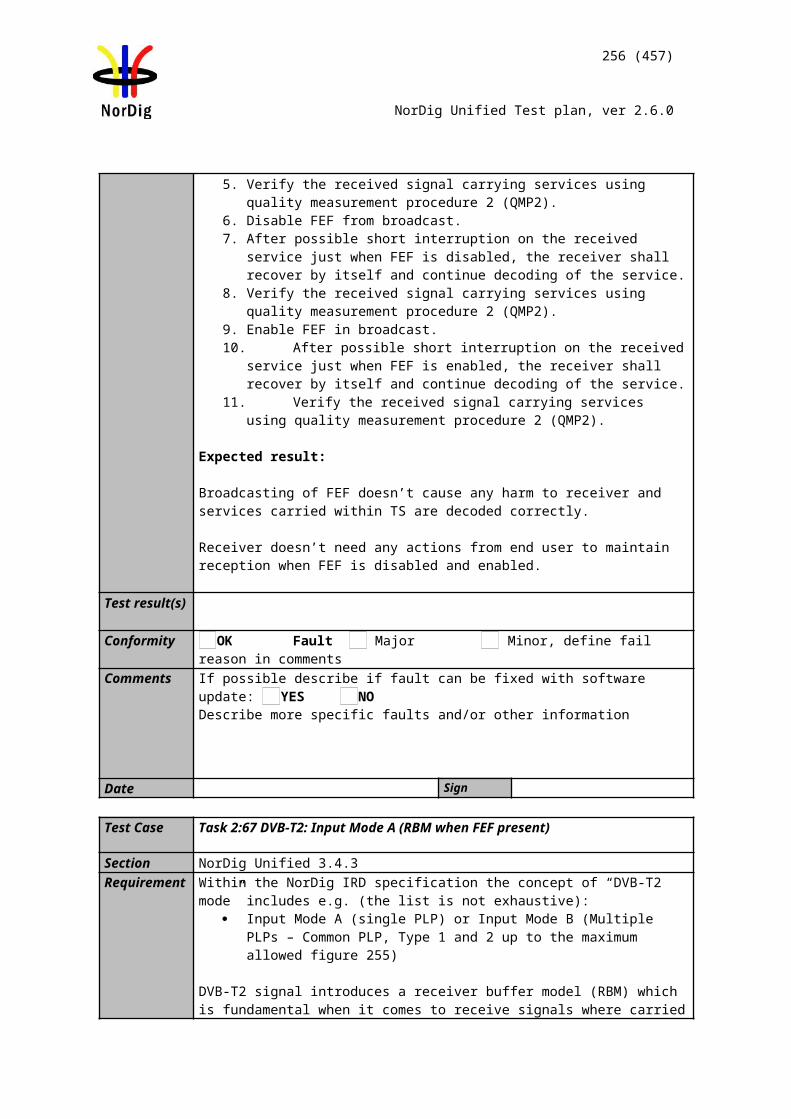
Source MUX Exciter DVB receiver
Monitor
256 (457)
NorDig Unified Test plan, ver 2.6.0
Date Sign
Test Case Task 6:7 Minimum video bandwidth
Section NorDig Unified 5.7Requirement The NorDig IRD shall provide support for very low bandwidth video.
For MPEG-2 video the decoder shall be able to decode at bit rates down to 1.0 Mbps for video resolutions up to full Standard Definition resolution video (720x576).
The NorDig IRD shall be able to decode H.264/AVC video at bitrates down to 250 kbps for all resolutions up to 1920x1080. For AVC still picture the NorDig IRD shall be able to decode down to 100 kbps.
IRD Profile(s) Basic, IRD, FETest procedure Purpose of test:
To verify that the receiver is able to decodevideo streams for very low bandwidth video.
Equipment:
A transport stream with following video content at: MPEG-2 MP@ML 720x576i 25Hz 1.0 Mbps MPEG-4 AVC HP@L3 720x576i 25Hz 250 kbps MPEG-4 AVC HP@L4 1280x720p 50Hz 250 kbps MPEG-4 AVC HP@L4 1920x1080i 25Hz 250 kbps
Test procedure:
Tune to the service(s) and verify that the IRD decodes very low bandwith video correctly.
If the 250kbit/s bit rate is not achieved, the tested bit rate shall be noted in comments.
Expected result:
The IRD supports low bitrate video as stipulated above..
Test result(s)Conformity OK Fault Major Minor, define fail reason in commentsComments If possible describe if fault can be fixed with software update: YES NO
Describe more specific faults and/or other information
Date Sign
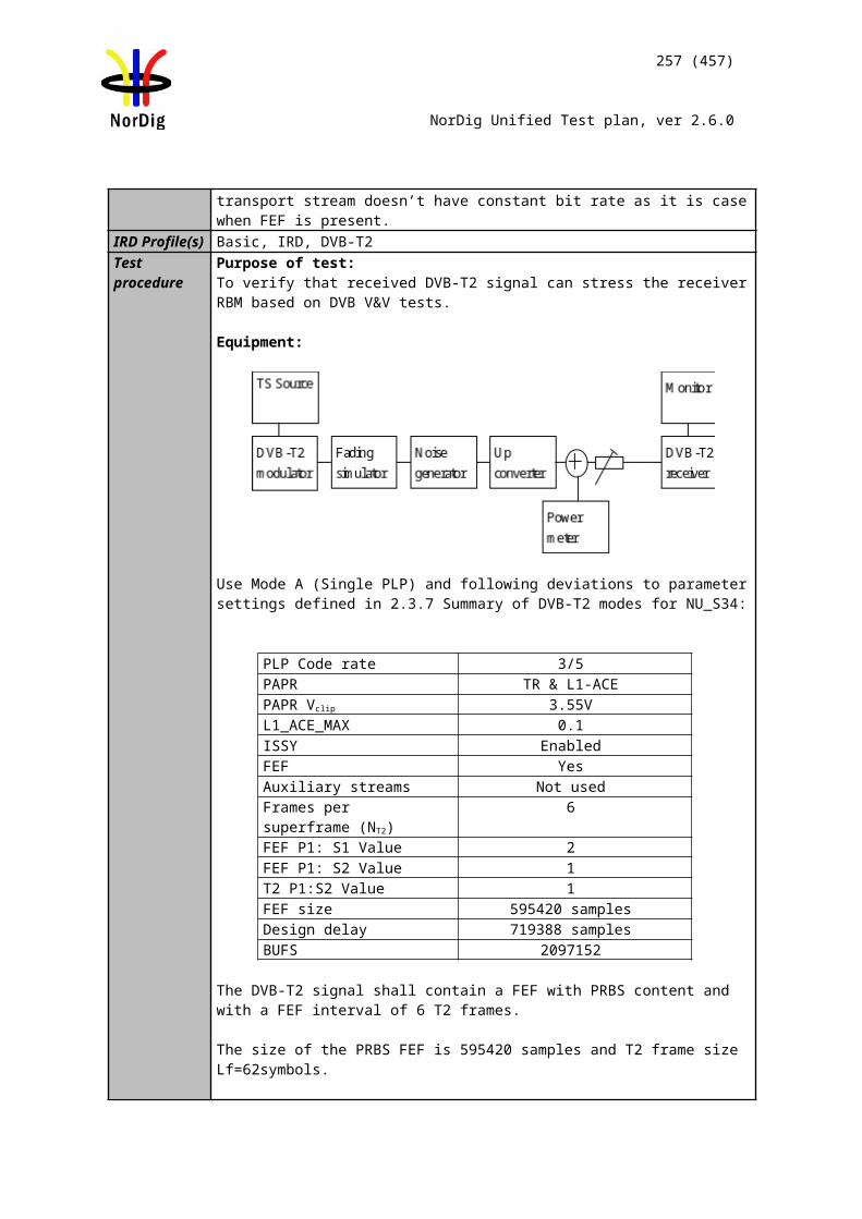
Source MUX Exciter DVB receiver
Monitor
257 (457)
NorDig Unified Test plan, ver 2.6.0
Test Case Task 6:8 Frame cropping
Section NorDig Unified 5.8Requirement The NorDig IRD shall support frame cropping for H.264/AVC encoded video. Frame
cropping signalling is used to indicate which area of the encoded video that should be displayed.
For 1080 line formats, the video is encoded with 1088 lines. To indicate which area of the encoded video that should be displayed, frame cropping signalling may be used. If frame cropping information is included in the encoded video, this shall be used to decide which 8 lines should be hidden in the Decoder Composition Output. If no frame cropping signalling is available, the IRD shall crop the bottom 8 lines.
IRD Profile(s) Basic, IRD, FETest procedure Purpose of test:
To verify that the receiver support frame cropping.
Equipment:
TS containing a service with frame cropping signalling for 8 lines (1080i) and a service without frame cropping (1080i).
Test procedure:1. Play out the transport stream containing a service with frame cropping information and another service without frame cropping information. 2. Verify that the desired lines are cropped. 3. Change to service without frame cropping information. 4.Verify that the bottom 8 lines are cropped.5. Fill in test results
Expected result:The IRD supports frame cropping correctly
Test result(s)Conformity OK Fault Major Minor, define fail reason in commentsComments If possible describe if fault can be fixed with software update: YES NO
Describe more specific faults and/or other information
Date Sign
Test Case Task 6:9 Overscan
Section NorDig Unified 5.9Requirement For services carrying H.264/AVC video, the broadcaster may use the
overscan_info_present and overscan_appropriate flags to indicate whether the receiver should apply this typical overscan or should display the complete broadcast video image. The flags will be encoded according to Table 5.3.
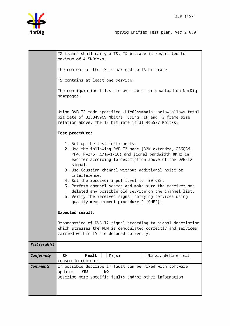
Source MUX Exciter DVB receiver
Monitor
258 (457)
NorDig Unified Test plan, ver 2.6.0
IRD Profile(s) Basic, IRD, FETest procedure Purpose of test:
To verify that the receiver support overscan.
Equipment:
TS containing a service with overscan signaling and a service without overscan.
Test procedure:1. Play out the transport stream containing a service with overscan information and another service without overscan information. 2. Verify that the desired behavior of the IRD happens. 3. Change to service without overscan information. 4. Verify that the desired behavior of the IRD happens.5. Fill in test results
Expected result:The IRD supports overscan correctly
Test result(s)Conformity OK Fault Major Minor, define fail reason in commentsComments If possible describe if fault can be fixed with software update: YES NO
Describe more specific faults and/or other information
Date Sign
Test Case Task 6:10 High Definition Video Output and Display
Section NorDig Unified 5.10Requirement The NorDig STBs shall be able to use the EDID information provided by the display to
determine automatically the STB output and to accept a manual setting of the STB output, as specified in section 8.6.
For NorDig iDTVs the output video shall always be converted to the display’s native resolution.
IRD Profile(s) Basic, IRD, FETest procedure
This requirement is tested in test caseTask 9:4.
Test Case Task 6:11 Down-conversion of High Definition Video for Standard Definition output
Section NorDig Unified 5.11
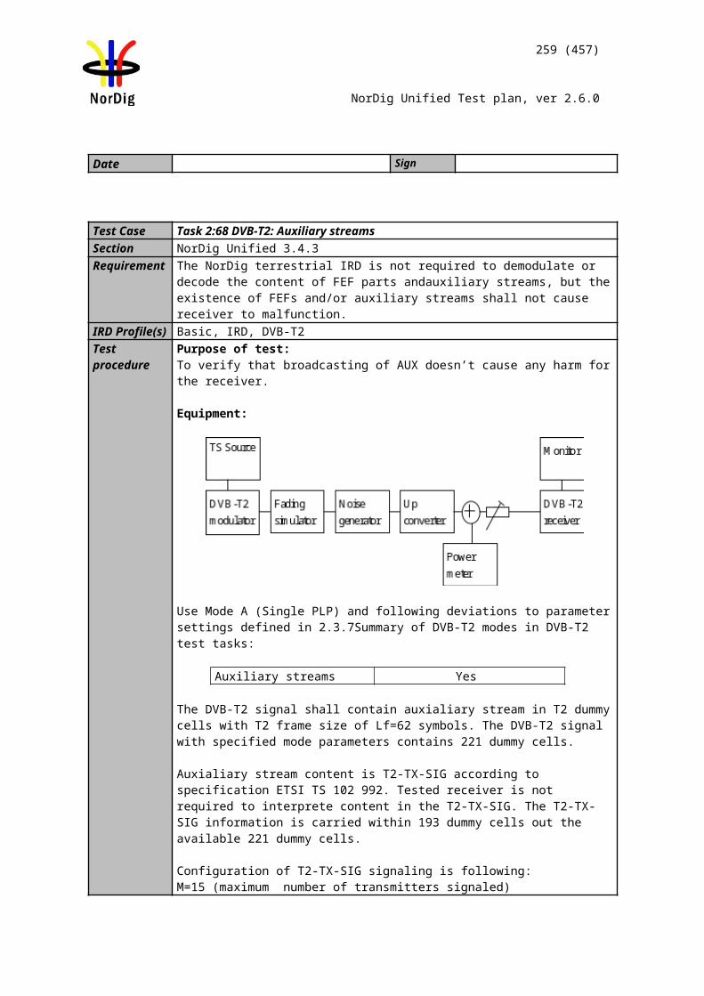
259 (457)
NorDig Unified Test plan, ver 2.6.0
Requirement If SCART, or any other analogue video output (Y, Pb, Pr, RF-PAL or CVBS) is available, the decoded High Definition video shall be down-converted by the SD Format Converter to Standard Definition resolution for output via these interfaces.
Down-conversion of pictures shall be implemented, from any of the incoming encoded HD full screen luminance resolution values (1920x1080, 1440x1080, 1280x1080, 960x1080, 1280x720, 960x720 and 640x720) to SD resolution (720x576).
When down-converting any 1:1 pixel aspect ratio format (i.e. 1280x720 or 1920x1080) in the Decoder Composition Output to 720x576 resolution, the target shall be 702x576 pixels to be centerd in the 720x576 grid with nine black pixels inserted as the start of the 720 pixel active line and nine pixels inserted as the end of the 720 pixel active line.
Down-converted HD video shall be displayed as 16:9 letterbox on 4:3 displays. (Allowing center cut would limit the safe area to 4:3 for HD production, hence not an allowed display option).
The SD Format Converter should apply appropriate re-interlacing (field mode integration re-interlacing). It shall process and output 720x576i25 in 4:3 frame aspect ratio or 16:9 frame aspect ratio video with colours according to 5.4 Colormertry.
IRD Profile(s) Basic, IRD, FETest procedure
This requirement is tested in test Task 9:8
Test Case Task 6:12 16:9 displayed on 4:3 monitors
Section NorDig Unified 5.12Requirement The Nordig IRDs shall have methods to display 16:9 transmitted content on a 4:3
monitor. Likewise Nordig IRDs and iDTVs shall have methods to display 4:3 transmitted content on a 16:9 monitor. The user shall have the ability to select appropriate aspect ratio for the analogue video output (SCART), see section 8.4.
IRD Profile(s) Basic, IRD, FETest procedure Purpose of test:
To verify that the IRD can output suitable picture signals for the 4:3 screen.
This test is not relevant for iDTV or PC based receivers in case the video is decoded to the integrated screen.For STBs or similar receivers with an external analog video output e.g. Y, Pb, Pr, RF-PAL, Y/C or CVBS, it is recommended the video aspect ratio can be re-formatted from 16:9 to 4:3 if so selected by the user. If the video signal is available on a SCART connector, the aspect ratio shall be signaled via pin 8 in the SCART connector, see test Error: Reference source not found. Line 23 and line 623 should be masked before the letterbox conversion to avoid the irritating half lines.
Test Equipment:Test signals are created using the test bed shown below:
260 (457)
NorDig Unified Test plan, ver 2.6.0
The multiplex should contain a number of services with 4:3 picture aspect ratio, and one service with 16:9 aspect ratio. All services in the multiplex are descrambled before recording.
Test procedure:
The IRD is tuned to a transport stream which contains a 16:9 aspect ratio video service. It is verified that the receiver can deliver a picture with the maintained 16:9 aspect ratio (Letterbox)
Expected result: Receiver can deliver a picture with the maintained 16:9 aspect ratio (Letterbox) on its external analog video output.
Note: During the transition period from 4:3 to pure 16:9 transmissions, dynamical changes of the aspect ratio, e.g. 16:9 -> 4:3 -> 16:9, may occur in broadcasting. It is highly recommended that IRD can provide always correct aspect ratio.
Test result(s)Conformity OK Fault Major Minor, define fail reason in commentsComments If possible describe if fault can be fixed with software update: YES NO
Describe more specific faults and/or other information
Date Sign
Test Case Task 6:13 Displaying 4:3 Material on 16:9 Monitors
Section NorDig Unified 5.12Requirement The Nordig IRDs shall have methods to display 16:9 transmitted content on a 4:3
monitor. Likewise Nordig IRDs and iDTVs shall have methods to display 4:3 transmitted content on a 16:9 monitor. The user shall have the ability to select appropriate aspect ratio for the analogue video output (SCART), see section 8.4.
IRD Profile(s) Basic, IRD, FETest procedure Purpose of test:
To verify that the IRD can output suitable picture signals for the 16:9 screen.
Equipment:Test signals are created using the test bed shown below:
Test procedure:
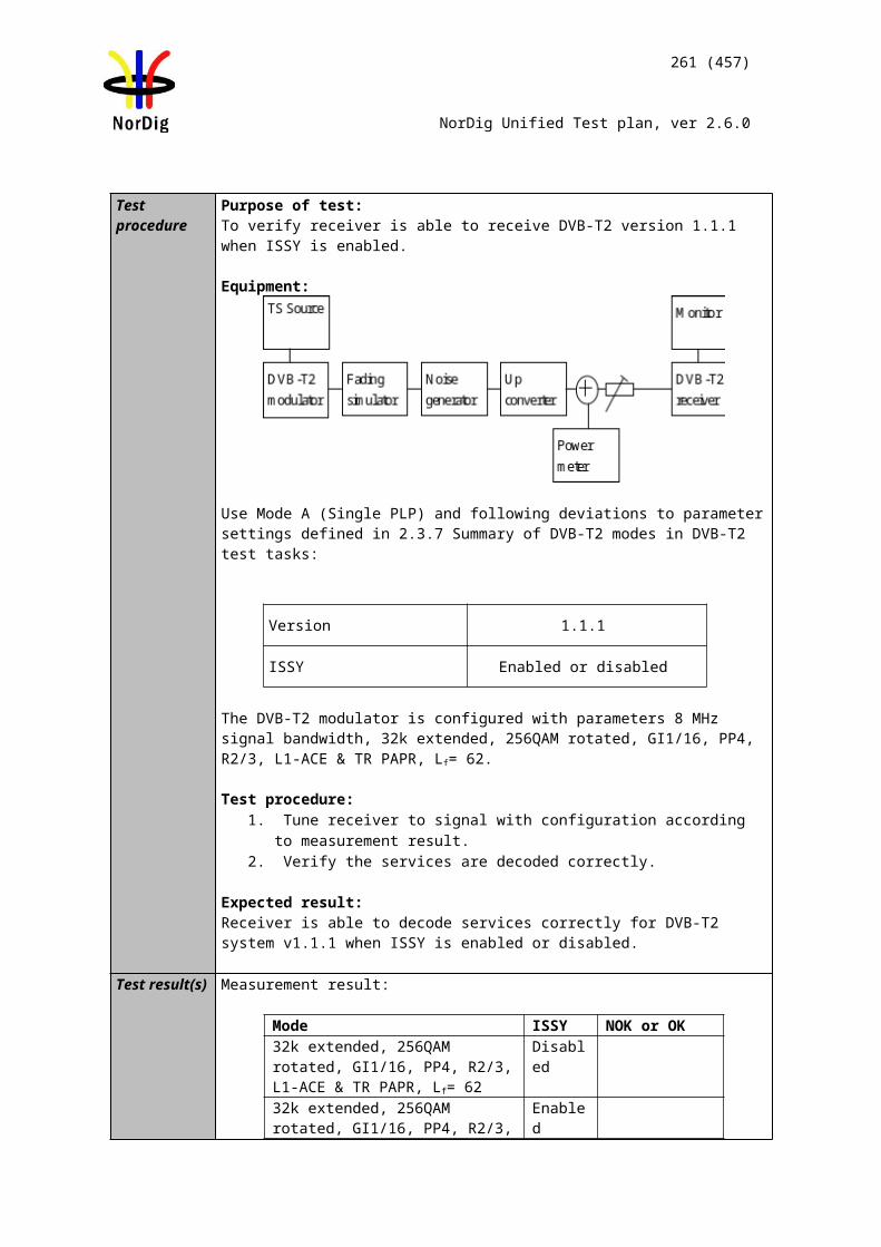
261 (457)
NorDig Unified Test plan, ver 2.6.0
This test can be done in parallel with Task 9:2.
The IRD is tuned to a transport stream containing a 4:3 aspect ratio video service. It is verified that the receiver can deliver a maintained full height 4:3 aspect ratio (Pillarbox) video signal for the 16:9 screen.
Expected result: Receiver can deliver a maintained full height 4:3 aspect ratio (Pillarbox) video signal for the 16:9 screen. Note: During the transition period from 4:3 to pure 16:9 transmissions, dynamical changes of the aspect ratio, e.g. 16:9 -> 4:3 -> 16:9, may occur in broadcasting. It is highly recommended that IRD can provide always correct aspect ratio.
Test result(s)Conformity OK Fault Major Minor, define fail reason in commentsComments If possible describe if fault can be fixed with software update: YES NO
Describe more specific faults and/or other information
Date Sign
Test Case Task 6:14 Rescaling for HbbTV application
Section NorDig Unified 5.13Requirement A NorDig Hybrid shall support rescaling as defined in HbbTV under “video scaling” in
clause 10.2.1 of ETSI TS 102 796 V1.2.1. These shall be supported for any of the valid incoming encoded full screen luminance resolution (see 5.2 for full screen luminance resolution values). The video shall be scaled, preserving the aspect ratio, such that all of the decoded video is visible witin the area of the AV Control object. (See HbbTV requirements in ETSI TS 102 796 Appendix E4).
IRD Profile(s) Hybrid, IRD, FETest procedure
This requirement is tested in test Task 14:
2.7 Task 7: AudioTest Case Task 7:1 Audio User Preference Settings
Section NorDig Unified 6.1.1Requirement The NorDig IRD shall have User Preference Settings for audio functions as stated in
section 16.2 (for example primary and secondary audio language, audio format, audio type, audio delay, etc).
IRD Profile(s) Basic, IRD, FETest procedure
This is general requirement that will be test in following tests.
Test result(s)Conformity OK Fault Major Minor, define fail reason in commentsComments If possible describe if fault can be fixed with software update: YES NO
Source MUX Exciter DVB receiver
Monitor
262 (457)
NorDig Unified Test plan, ver 2.6.0
Describe more specific faults and/or other information
Date Sign
Test Case Task 7:2 MPEG-1 Layer II: Requirements
Section NorDig Unified 6.2.1.1Requirement The NorDig IRD shall support:
• decode MPEG-1 Layer II streams at all bit rates and sample rates listed in ETSI TS 101 154 [29].The NorDig IRD should support:• decode MPEG-1 Layer II streams at half-sampling rates (22.05 and 24 kHz).
IRD Profile(s) Basic, IRD, FETest procedure
This is general requirement that will be test in following tests.
Test result(s)Conformity OK Fault Major Minor, define fail reason in commentsComments If possible describe if fault can be fixed with software update: YES NO
Describe more specific faults and/or other information
Date Sign
Test Case Task 7:3 MPEG-1 Layer II: Analogue audio output
Section NorDig Unified 6.2, 6.2.1.1Requirement The NorDig IRD with SCART and/or analogue outputs shall always have an audio
signal present on the analogue outputs (SCART and stereo out, see section 8.5 and to built-in loudspeakers (see note 1)) if any of the supported formats is received.
The NorDig IRD shall support:• decode MPEG-1 Layer II streams at all bit rates and sample rates listed in ETSI TS 101 154 [29].
IRD Profile(s) Basic, IRD, FETest procedure Purpose of test:
To verify that receiver decodes MPEG-1 Layer II streams at all bit rates and sample rates and audio level can be adjusted.
Equipment:
A transport stream with following MPEG-1 Layer II audio content: audio_mode = ‘0’ (stereo), data rate = 192 kbit/s, at least one of the sampling
frequencies: 32, 44.1 or 48 kHz audio_mode = ‘1’, ‘2’ (dual channel), data rate = 192 kbit/s, at least one of the
sampling frequencies: 32, 44.1 or 48 kHz audio_mode = ‘3’ (single channel), data rate: 96 kbit/s, sampling frequency: 48
kHz
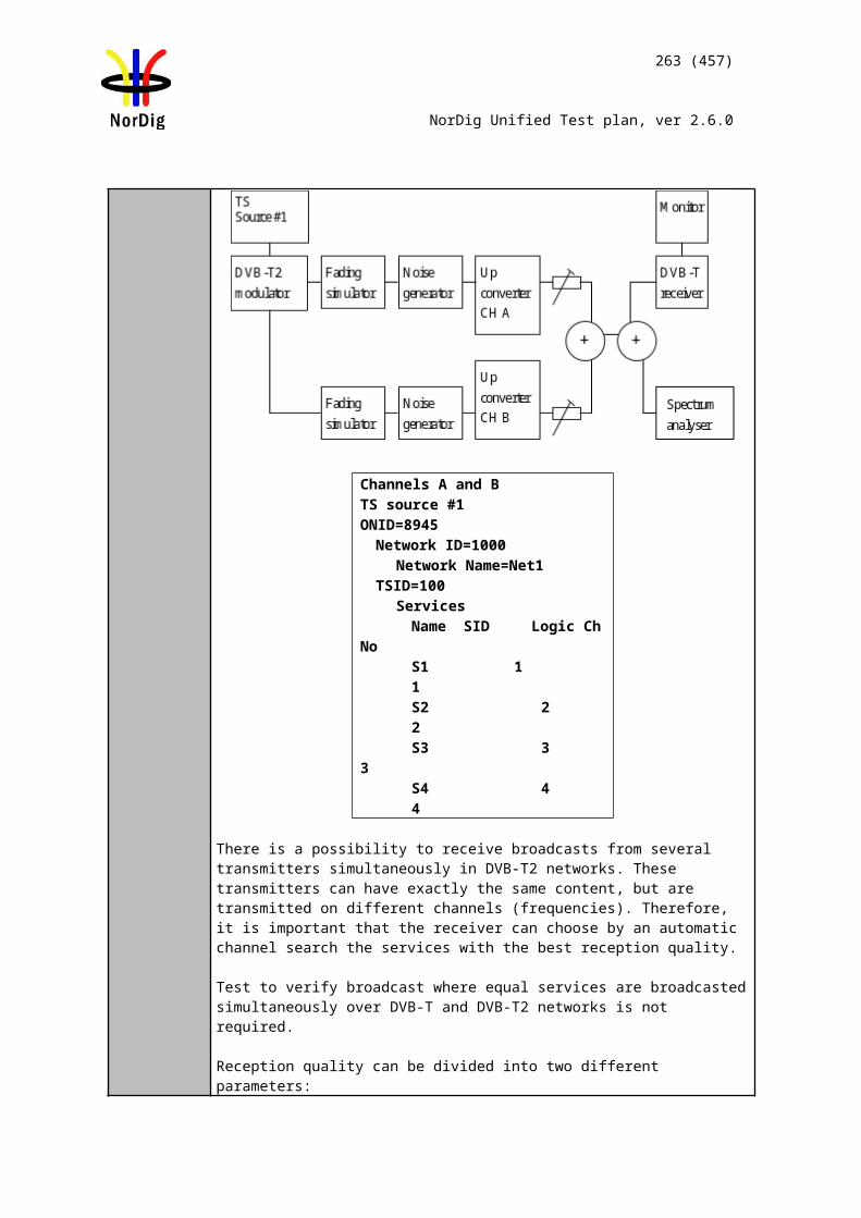
Source MUX Exciter DVB receiver
Monitor
263 (457)
NorDig Unified Test plan, ver 2.6.0
Test procedure:
The IRD is tuned to a service containg all the combinations of the MPEG-1 Layer II audio parameters above.
The audio level is adjusted in the audio output.
Expected result:
IRD supports MPEG-1 Layer II audio decoding and audio is available properly in analoque audio output(s).
The audio output level can be adjusted.
est result(s)Conformity OK Fault Major Minor, define fail reason in commentsComments If possible describe if fault can be fixed with software update: YES NO
Describe more specific faults and/or other information
Date Sign
Test Case Task 7:4 MPEG-1 Layer II: HDMI output interface
Section NorDig Unified 6.2.1.2, 6.2.1.1Requirement The NorDig IRD shall be capable of providing the following formats on the HDMI
output connector from an MPEG-1 Layer II bitstream (see section 16 for factory default settings):• Decoded to PCM stereo bitstream.
The NorDig IRD shall support:• decode MPEG-1 Layer II streams at all bit rates and sample rates listed in ETSI TS 101 154 [29].
IRD Profile(s) Basic, IRD, FETest procedure Purpose of test:
To verify that receiver decodes MPEG-1 Layer II streams at all bit rates and sample rates to HDMI output interface and audio level can be adjusted.
This test is mandatory for STBs and IDTVs supporting HDMI output or HDMI ARC.
Equipment:
A transport stream with following MPEG-1 Layer II audio content: audio_mode = ‘0’ (stereo), data rate = 192 kbit/s, at least one of the sampling
frequencies: 32, 44.1 or 48 kHz audio_mode = ‘1’, ‘2’ (dual channel), data rate = 192 kbit/s, at least one of the
sampling frequencies: 32, 44.1 or 48 kHz audio_mode = ‘3’ (single channel), data rate: 96 kbit/s, sampling frequency: 48
Source MUX Exciter DVB receiver
Monitor
264 (457)
NorDig Unified Test plan, ver 2.6.0
kHz
Test procedure:
The IRD is tuned to a service containg all the combinations of the MPEG-1 Layer II audio parameters above. This task can be done parallel with Error: Reference source notfound.
The audio level is adjusted in the audio output.
Expected result:
IRD supports MPEG-1 Layer II audio decoding and audio is available properly in HDMI output in PCM stereo bit stream format independently of the user setting for stereo or multichannel.
The audio output level can be adjusted.Test result(s)Conformity OK Fault Major Minor, define fail reason in commentsComments If possible describe if fault can be fixed with software update: YES NO
Describe more specific faults and/or other information
Date Sign
Test Case Task 7:5 MPEG-1 Layer II: S/PDIF output interface
Section NorDig Unified 6.2.1.2, 6.2.1.1Requirement The NorDig IRD including an S/PDIF output shall be capable of providing the following
formats on the S/PDIF connector from an MPEG-1 Layer II bitstream:• Decoded to PCM stereo bitstream
The NorDig IRD shall support:• decode MPEG-1 Layer II streams at all bit rates and sample rates listed in ETSI TS 101 154 [29].
IRD Profile(s) Basic, IRD, FETest procedure Purpose of test:
To verify that receiver decodes MPEG-1 Layer II streams at all bit rates and sample rates to S/PDIF output interface.
Equipment:
A transport stream with following MPEG-1 Layer II audio content: audio_mode = ‘0’ (stereo), data rate = 192 kbit/s, at least one of the sampling
frequencies: 32, 44.1 or 48 kHz audio_mode = ‘1’, ‘2’ (dual channel), data rate = 192 kbit/s, at least one of the
sampling frequencies: 32, 44.1 or 48 kHz audio_mode = ‘3’ (single channel), data rate: 96 kbit/s, sampling frequency: 48
kHz
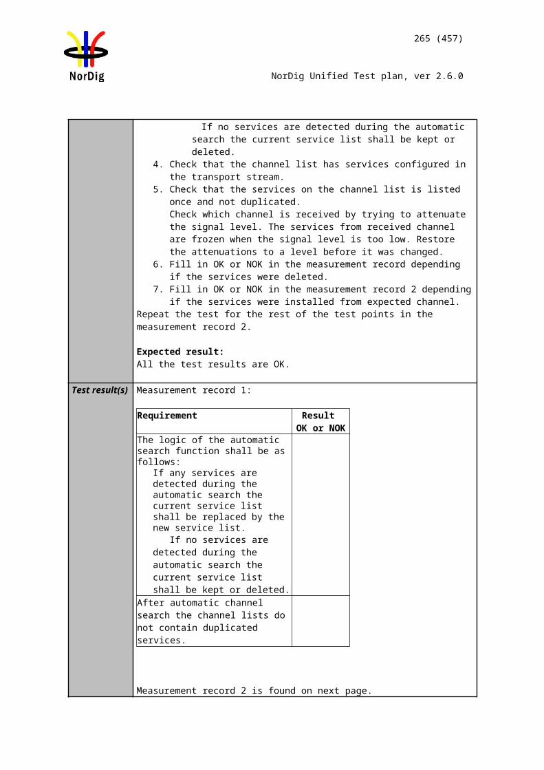
265 (457)
NorDig Unified Test plan, ver 2.6.0
Test procedure:
The IRD is tuned to a service containg all the combinations of the MPEG-1 Layer II audio parameters above. This task can be done parallel with Error: Reference source notfound.
Expected result:
IRD supports MPEG-1 Layer II audio decoding and audio is available properly in S/PDIF output in PCM stereo bit stream format independently of the user setting for stereo or multichannel.
Test result(s)Conformity OK Fault Major Minor, define fail reason in commentsComments If possible describe if fault can be fixed with software update: YES NO
Describe more specific faults and/or other information
Date Sign
Test Case Task 7:6 AC-3: Requirements
Section NorDig Unified 6.2.2Requirement NorDig IRD supporting E-AC-3 and AC-3 shall
• decode AC-3 streams at all bit rates and sample rates listed in ETSI TS 102 366 [35] (not including Annex E).• (additionally) decode E-AC-3 streams with data rates from 32 kbps to 3 024 kbps andsupport all sample rates listed in TS 102 366 [35] Annex E.• be capable of transcoding E-AC-3 bitstreams to AC-3 bitstreams according to TS 102366 [35]. Transcoding to AC-3 audio streams shall be at a fixed bit rate of 640 kbps.
IRD Profile(s) Basic, IRD, FETest procedure Purpose of test:
To verify that the IRD supports different AC-3 bit rates and sampling rates.
Equipment:
The TS shall contain services, which has a AC-3 (mono,stereo) audio component with relevant signaling at bit rates and
sampling rates:o Sampling rates 32, 44,1 and 48 kHzo Bit rates 64, 192, 384 and 640 kbit/s
a AC-3 (multichannel) audio component with relevant signaling at bit rates and sampling rates:
o Sampling rates 32, 44,1 and 48 kHzo Bit rate 64, 192, 384 and 640 kbit/s
Test procedure:
Source MUX Exciter DVB Receiver
Audio decoder
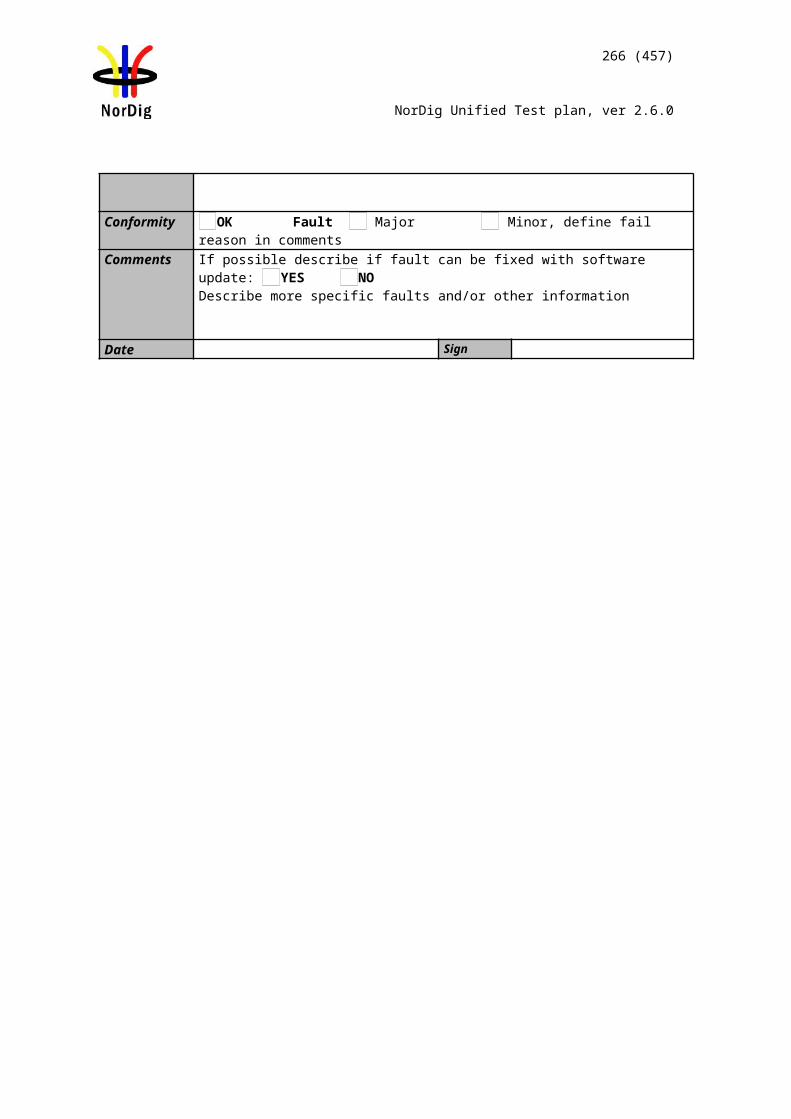
266 (457)
NorDig Unified Test plan, ver 2.6.0
1. Connect the IRD to an audio receiver, e.g. Home Theater System with HDMI.2. Verify that service has a multichannel AC-3 audio available.3. In receiver menu, select MPEGstereo audio.4. Verify that AC-3 multichannel is decoded and downmixed to PCM stereo
bitstream for HDMI output and if supported for HDMI ARC.5. Verify the audio output level can be adjusted.6. In receiver menu, select multichannel audio.7. Verify that AC-3 multichannel is passed-through as native bitstream for HDMI
output.
8. Verify that service has a stereo AC-3 audio available.9. In receiver menu, select MPEGstereo audio.10. Verify that AC-3 stereol is decoded and downmixed to PCM stereo bitstream
for HDMI output and if supported for HDMI ARC.11. Verify the audio output level can be adjusted.12. In receiver menu, select multichannel audio.13. Verify that AC-3 stereo is passed-through as native bitstream for HDMI output.
Expected result:
IRD supports for AC-3 input audio signal and down-mix to stereo.
Test result(s)Bit rate Sampling
rateNOK or OK
monostereoMultichannel 5.1Down-mix to stereo N/A N/A
Conformity OK Fault Major Minor, define fail reason in commentsComments If possible describe if fault can be fixed with software update: YES NO
Describe more specific faults and/or other information
Date Sign
Test Case Task 7:7 AC-3: Analogue audio output
Section NorDig Unified 6.2.2Requirement The NorDig IRD with SCART and/or analogue outputs shall always have an audio
signal present on the analogue outputs (SCART and stereo out, see section 8.5 and to built-in loudspeakers (see note 1)) if any of the supported formats is received.
If the NorDig IRD has analogue stereo output(s), it shall be capable of decoding and downmixing the supported audio formats for the analogue outputs.
NorDig IRD supporting E-AC-3 and AC-3 shall• decode AC-3 streams at all bit rates and sample rates listed in ETSI TS 102 366 [36] (not including Annex E).
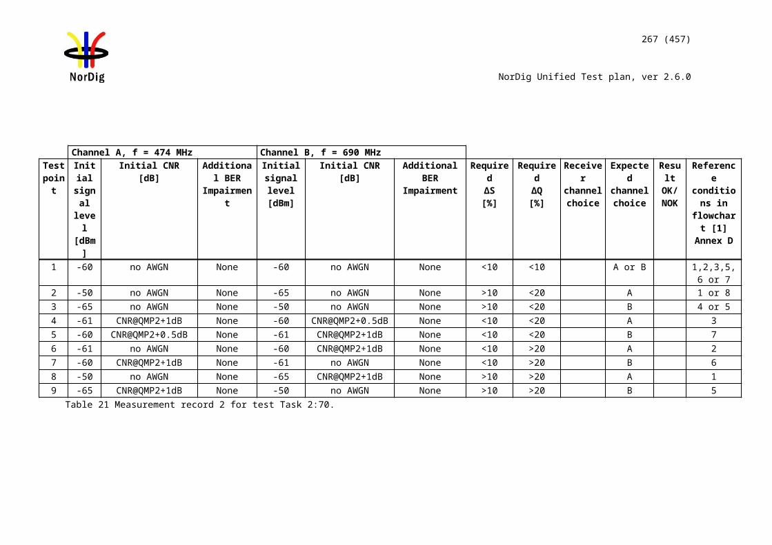
Source MUX Exciter DVB receiver
Monitor
267 (457)
NorDig Unified Test plan, ver 2.6.0
IRD Profile(s) Basic, IRD, FETest procedure Purpose of test:
To verify that receiver decodes AC-3 bitstream and audio output level can be adjusted.
This test in only mandatory for STB or IDTV with SCART or analogue audio output interface.
Equipment:
A transport stream containing aservice with AC-3 multichannel audio
Test procedure:
1. Verify that service has a multichannel AC-3 audio available.2. In receiver menu, select stereo audio audio.3. Verify that service containing AC-3 multichannel audio is downmixed to stereo
at analog audio output.4. In receiver menu, select multichannel audio.5. Verify that AC-3 multichannel is downmixed to stereo at analog audio output.6. Verify it is possible to adjust audio output level.
Expected result:
IRD supports AC-3 audio decoding and audio is downmixed to stereo in analog audio output(s).
The audio output level can be adjusted.
Test result(s)Conformity OK Fault Major Minor, define fail reason in commentsComments If possible describe if fault can be fixed with software update: YES NO
Describe more specific faults and/or other information
Date Sign
Test Case Task 7:8 AC-3: HDMI output and HDMI ARC interface
Section NorDig Unified 6.2.2Requirement NorDig IRDs supporting E-AC-3 and AC-3 shall be capable of providing the following
formats on the HDMI output connector connector from an E-AC-3 or AC-3 bitstream (see chapter 16 for factory default settings):• Pass-through of native bitstream (AC-3 and E-AC-3).• E-AC-3 bitstream transcoded to AC-3 bitstream.• Decoded and downmixed (if > 2 channels) to PCM stereo bitstream
NorDig IRD supporting E-AC-3 and AC-3 shall• decode AC-3 streams at all bit rates and sample rates listed in ETSI TS 102 366 [36] (not including Annex E).
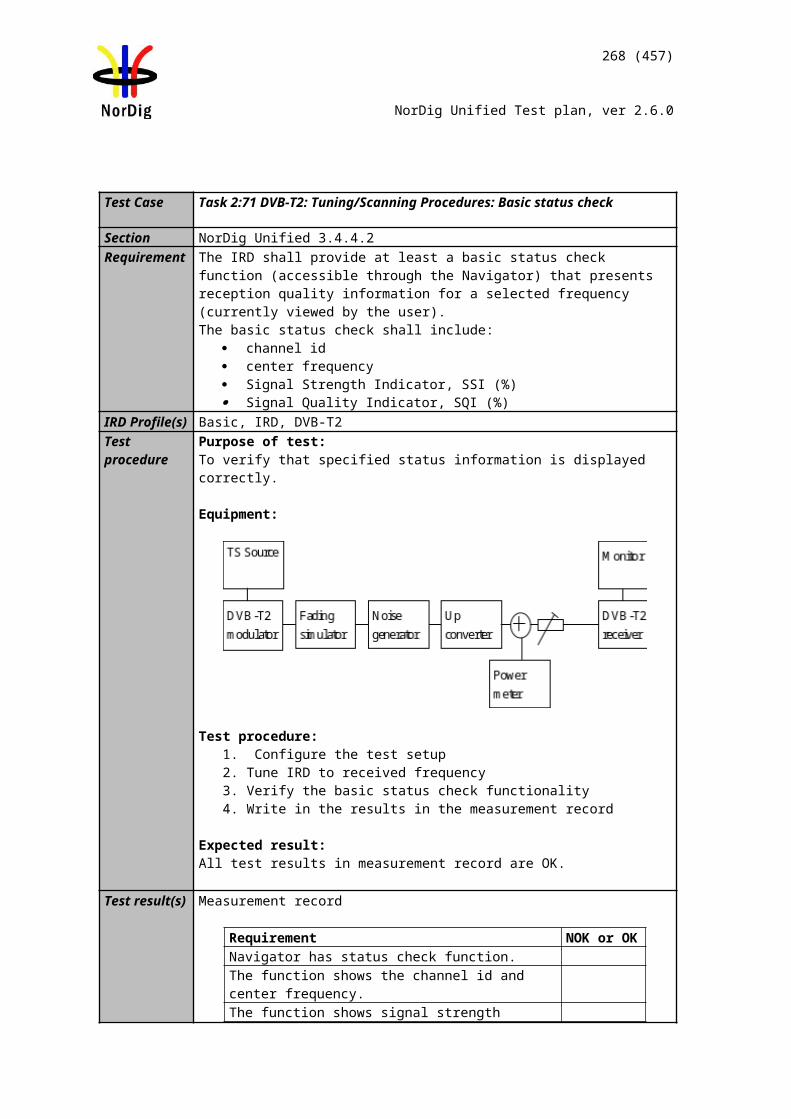
MPEG-2 source
MUX Exciter DVB receiver
HDMI receiver
Monitor
268 (457)
NorDig Unified Test plan, ver 2.6.0
IRD Profile(s) Basic, IRD, FETest procedure Purpose of test:
To verify that receiver decodes and passes-through AC-3 bitstream and the audio output level for decoded AC-3 bitstream can be adjusted.
This test in only relevant for IRD with HDMI output or HDMI ARC.
Equipment:
A transport stream containing aservice with AC-3 multichannel audio.
Test procedure:
1. Connect the IRD to an HDMI receiver, e.g. Home Theater System with HDMI.2. Verify that service has a multichannel AC-3 audio available.3. In receiver menu, select MPEG stereo audio.4. Verify that AC-3 multichannel is decoded and downmixed to PCM stereo
bitstream for HDMI output and if supported for HDMI ARC.5. Verify the audio output level can be adjusted.6. In receiver menu, select multichannel audio.7. Verify that AC-3 multichannel is passed-through as native bitstream for HDMI
output.
Expected result:
IRD supports AC-3 audio decoding and downmixing to PCM stereo when stereo audio is selected and the audio output level can be adjusted.
IRD supports AC-3 audio pass-through native bitstream when multichannel audio is selected.
Test result(s)Conformity OK Fault Major Minor, define fail reason in commentsComments If possible describe if fault can be fixed with software update: YES NO
Describe more specific faults and/or other information
Date Sign
Test Case Task 7:9 AC-3: S/PDIF output interface
Section NorDig Unified 6.2.2Requirement The NorDig IRD supporting E-AC-3 and AC-3 and including an S/PDIF output shall be
MPEG-2 source
MUX Exciter DVB receiver
S/PDIF receiver
Monitor
269 (457)
NorDig Unified Test plan, ver 2.6.0
capable of providing the following formats on the S/PDIF connector from an E-AC-3 or AC-3 bitstream:• E-AC-3 bitstream transcoded to AC-3 bitstream• Decoded and downmixed (if > 2 channels) to PCM stereo bitstream• Pass-through of AC-3 bitstream
NorDig IRD supporting E-AC-3 and AC-3 shall• decode AC-3 streams at all bit rates and sample rates listed in ETSI TS 102 366 [36] (not including Annex E).
IRD Profile(s) Basic, IRD, FETest procedure Purpose of test:
To verify that receiver decodes and passes-through AC-3 bitstream.
This test is only relevant for IRD with S/PDIF output.
Equipment:
A transport stream containing aservice with AC-3 multichannel audio.
Test procedure:
1. Connect the IRD to a S/PDIF receiver e.g. Home Theater System with S/PDIF.2. Verify that service has a multichannel AC-3 audio available.3. In receiver menu, select stereo audio.4. Verify that AC-3 multichannel is decoded and downmixed to PCM stereo
bitstream for S/PDIF output.5. Verify the audio output level can be adjusted.6. In receiver menu, select multichannel audio.7. Verify that AC-3 multichannel is passed-through as native bitstream for S/PDIF
output.
Expected result:
IRD supports AC-3 audio decoding and downmixing to PCM stereo when stereo audio is selected.
IRD supports AC-3 audio pass-through native bitstream when multichannel audio is selected.
Test result(s)Conformity OK Fault Major Minor, define fail reason in commentsComments If possible describe if fault can be fixed with software update: YES NO
Describe more specific faults and/or other information
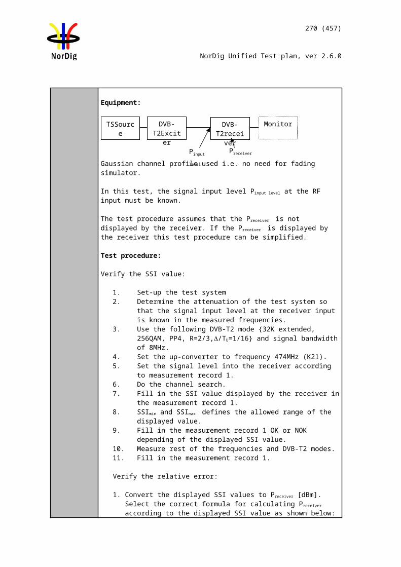
Audio decoder
MUX Exciter IRDTS Source
270 (457)
NorDig Unified Test plan, ver 2.6.0
Date Sign
Test Case Task 7:10 AC-3: Metadata
Section NorDig Unified 6.2.2.2Requirement The NorDig IRD supporting E-AC-3 and AC-3 shall support the use of a complete set of
Dolby metadata [36] embedded in the audio stream when decoding AC-3 or E-AC-3 bitstreams, transcoding E-AC-3 bitstreams to AC-3, or creating a PCM stereo downmix from a decoded EAC-3 or AC-3 bitstream.
IRD Profile(s) Basic, IRD, FETest procedure TBD
Test result(s)Conformity OK Fault Major Minor, define fail reason in commentsComments If possible describe if fault can be fixed with software update: YES NO
Describe more specific faults and/or other information
Date Sign
Test Case Task 7:11 E-AC-3: Requirements
Section NorDig Unified 6.2.2Requirement NorDig IRD supporting E-AC-3 and AC-3 shall
• decode AC-3 streams at all bit rates and sample rates listed in ETSI TS 102 366 [36] (not including Annex E).•(additionally) decode E-AC-3 streams with data rates from 32 kbps to 3 024 kbps and support all sample rates listed in TS 102 366 [36] Annex E.• be capable of transcoding E-AC-3 bitstreams to AC-3 bitstreams according to TS 102 366 [36]. Transcoding to AC-3 audio streams shall be at a fixed bit rate of 640 kbps.
IRD Profile(s) Basic, IRD, FETest procedure Purpose of test:
To verify that the IRD supports different E-AC-3 bit rates and sampling rates.
Equipment:
The TS shall contain services, which has a E-AC-3 (mono,stereo) audio component with relevant signaling at bit rates
and sampling rates:o Sampling rates 32, 44,1 and 48 kHz
Bit rates 64, 192, 384 and 640 kbit/s a E-AC-3 (multichannel) audio component with relevant signaling at bit rates and sampling rates:
o Sampling rates 32, 44,1 and 48 kHzBit rates 64, 192, 384 and 640 kbit/s Test procedure:
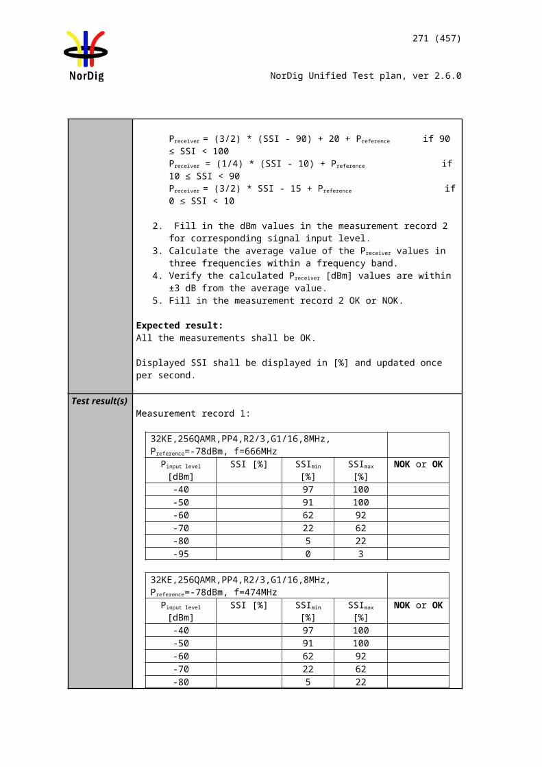
271 (457)
NorDig Unified Test plan, ver 2.6.0
1. Connect the IRD to an audio receiver, e.g. Home Theater System with HDMI.2. Verify that service has a multichannel E-AC-3 audio available.3. In receiver menu, select MPEGstereo audio.4. Verify that E-AC-3 multichannel is decoded and downmixed to PCM stereo
bitstream for HDMI output and if supported for HDMI ARC.5. Verify the audio output level can be adjusted.6. In receiver menu, select multichannel audio.7. Verify that E-AC-3 multichannel is passed-through as native bitstream for
HDMI output.
8. Verify that service has a stereo E-AC-3 audio available.9. In receiver menu, select MPEGstereo audio.10. Verify that E-AC-3 stereo is decoded and downmixed to PCM stereo bitstream
for HDMI output and if supported for HDMI ARC.11. Verify the audio output level can be adjusted.12. In receiver menu, select multichannel audio.13. Verify that E-AC-3 stereo is passed-through as native bitstream for HDMI
output.
Expected result:
IRD supports for E-AC-3 input audio signal and down-mix to stereo.
Test result(s)Bit rate Sampling
rateNOK or OK
monostereoMultichannel 5.1Down-mix to stereo N/A N/A
Conformity OK Fault Major Minor, define fail reason in commentsComments If possible describe if fault can be fixed with software update: YES NO
Describe more specific faults and/or other information
Date Sign
Test Case Task 7:12 E-AC-3: Analogue audio output
Section NorDig Unified 6.2.2Requirement The NorDig IRD with SCART and/or analogue outputs shall always have an audio
signal present on the analogue outputs (SCART and stereo out, see section 8.5 and to built-in loudspeakers (see note 1)) if any of the supported formats is received.
If the NorDig IRD has analogue stereo output(s), it shall be capable of decoding and downmixing the supported audio formats for the analogue outputs.
NorDig IRD supporting E-AC-3 and AC-3 shall• (additionally) decode E-AC-3 streams with data rates from 32 kbps to 3 024 kbps and support all sample rates listed in TS 102 366 [36] Annex E.
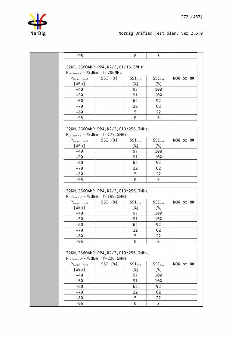
Source MUX Exciter DVB receiver
Monitor
272 (457)
NorDig Unified Test plan, ver 2.6.0
IRD Profile(s) Basic, IRD, FETest procedure Purpose of test:
To verify that receiver decodes E-AC-3 bitstream and audio output level can be adjusted.
This test in only mandatory for STB or IDTV with SCART or analogue audio output interface.
Equipment:
A transport stream containing aservice with E-AC-3 multichannel audio.
Test procedure:
1. Verify that service has a multichannel E-AC-3 audio available.2. In receiver menu, select MPEG-1 Layer II audio, (Sometimes called PCM).3. Verify that E-AC-3 multichannel is downmixed to stereo at analog audio
output.4. In receiver menu, select multichannel audio.5. Verify that E-AC-3 multichannel is downmixed to stereo at analog audio
output.
Expected result:
IRD supports E-AC-3 audio decoding and audio is downmixed to stereo in analog audio output(s).
The audio output level can be adjusted.
Test result(s)Conformity OK Fault Major Minor, define fail reason in commentsComments If possible describe if fault can be fixed with software update: YES NO
Describe more specific faults and/or other information
Date Sign
Test Case Task 7:13 E-AC-3: HDMI output and HDMI ARC interface
Section NorDig Unified 6.2.2Requirement NorDig IRDs supporting E-AC-3 and AC-3 shall be capable of providing the following
formats on the HDMI output connector connector from an E-AC-3 or AC-3 bitstream (see chapter 16 for factory default settings):• Pass-through of native bitstream (AC-3 and E-AC-3).• E-AC-3 bitstream transcoded to AC-3 bitstream.• Decoded and downmixed (if > 2 channels) to PCM stereo bitstream
NorDig IRD supporting E-AC-3 and AC-3 shall
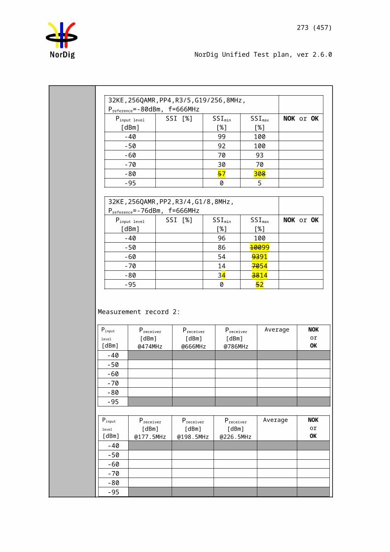
MPEG-2 source
MUX Exciter DVB receiver
HDMI receiver
Monitor
273 (457)
NorDig Unified Test plan, ver 2.6.0
• (additionally) decode E-AC-3 streams with data rates from 32 kbps to 3 024 kbps and support all sample rates listed in TS 102 366 [36] Annex E.• be capable of transcoding E-AC-3 bitstreams to AC-3 bitstreams according to TS 102 366 [36]. Transcoding to AC-3 audio streams shall be at a fixed bit rate of 640 kbps.
IRD Profile(s) Basic, IRD, FETest procedure Purpose of test:
To verify that receiver decodes/transcodes and passes-through E-AC-3 bitstream.To verify for the decoded E-AC-3 bitstream that the audio output level can be adjusted.
This test in only relevant for IRD with HDMI output.
Equipment:
A transport stream with E-AC-3 multichannel audio.
Test procedure:
1. Connect the IRD to an HDMI receiver e.g. Home Theater System with HDMI.2. Verify that service has a multichannel E-AC-3 audio available.3. In receiver menu, select stereo audio.4. Verify that E-AC-3 multichannel is decoded and downmixed to PCM stereo
bitstream for HDMI output.5. Verify the audio output level can be adjusted.6. In receiver menu, select multichannel audio.7. Verify that E-AC-3 multichannel is passed-through as native bitstream* for
HDMI output or transcoded to AC-3.
* Receiving device supports E-AC-3 bitstream.
Expected result:
IRD supports E-AC-3 audio decoding and downmixing to PCM stereo when stereo audio is selected.
IRD supports AC-3 audio pass-through native bitstream for HDMI output and/or HDMI ARC or transcode it to AC-3 if receiving device does not support E-AC-3 when multichannel audio is selected.
Test result(s)Conformity OK Fault Major Minor, define fail reason in commentsComments If possible describe if fault can be fixed with software update: YES NO
Describe more specific faults and/or other information
Date Sign
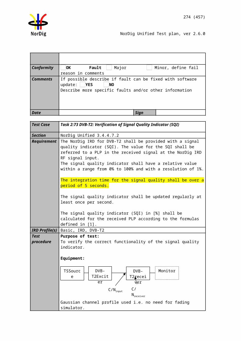
MPEG-2 source
MUX Exciter DVB receiver
S/PDIF receiver
Monitor
274 (457)
NorDig Unified Test plan, ver 2.6.0
Test Case Task 7:14 E-AC-3: S/PDIF output interface
Section NorDig Unified 6.2.2Requirement The NorDig IRD supporting E-AC-3 and AC-3 and including an S/PDIF output shall be
capable of providing the following formats on the S/PDIF connector from an E-AC-3 or AC-3 bitstream:• E-AC-3 bitstream transcoded to AC-3 bitstream• Decoded and downmixed (if > 2 channels) to PCM stereo bitstream• Pass-through of AC-3 bitstream
NorDig IRD supporting E-AC-3 and AC-3 shall• (additionally) decode E-AC-3 streams with data rates from 32 kbps to 3 024 kbps and support all sample rates listed in TS 102 366 [36] Annex E.• be capable of transcoding E-AC-3 bitstreams to AC-3 bitstreams according to TS 102 366 [36]. Transcoding to AC-3 audio streams shall be at a fixed bit rate of 640 kbps.
IRD Profile(s) Basic, IRD, FETest procedure Purpose of test:
To verify that receiver decodes/transcodes E-AC-3 bitstream.
This test is only relevant for IRD with S/PDIF output.
Equipment:
A transport stream with E-AC-3 multichannel audio.
Test procedure:
1. Connect the IRD to a S/PDIF receiver e.g. Home Theater System with S/PDIF.2. Verify that service has a multichannel E-AC-3 audio available.3. In receiver menu, select stereo audio.4. Verify that E-AC-3 multichannel is decoded and downmixed to PCM stereo
bitstream for S/PDIF output.5. In receiver menu, select multichannel audio.6. Verify that E-AC-3 multichannel is passed-through as native bitstream for
S/PDIF output.
Expected result:
IRD supports E-AC-3 audio decoding to PCM stereo bitstream when stereo audio is selected. IRD supports E-AC-3 transcode to AC-3 when multichannel audio is selected.
Test result(s)Conformity OK Fault Major Minor, define fail reason in comments
Audio decoder
MUX Exciter IRDTS Source
275 (457)
NorDig Unified Test plan, ver 2.6.0
Comments If possible describe if fault can be fixed with software update: YES NODescribe more specific faults and/or other information
Date Sign
Test Case Task 7:15 E-AC-3: Metadata
Section NorDig Unified 6.2.2.2Requirement The NorDig IRD supporting E-AC-3 and AC-3 shall support the use of a complete set of
Dolby metadata [36] embedded in the audio stream when decoding AC-3 or E-AC-3 bitstreams, transcoding E-AC-3 bitstreams to AC-3, or creating a PCM stereo downmix from a decoded EAC-3 or AC-3 bitstream.
IRD Profile(s) Basic, IRD, FETest procedure Purpose of test:
To verify that the IRD supports Dolby metadata.
Equipment:
The TS shall contain a service E-AC-3, which has the following metadata included in audio component:
DolbyDynamicRange Control
Dolby Dialogue Normalization according to ISO/IEC 14496-3 : 2005 (Audio 3rd edition)
Down Mix parameters
Test procedure:
1. Setup the system2. Connect audio decoder to HDMI output. 3. Verify that the IRD supports metadata correctly for decoding of the E-AC-3
stereo4. Verify that the IRD supports metadata correctly for transcoding E-AC-3
multichannel to AC-3.5. Verify that the IRD supports metadata correctly for creating PCM stereo
downmix.
Expected result: IRD shall support E-AC-3 metadata according to requirement.
Test result(s)Conformity OK Fault Major Minor, define fail reason in commentsComments If possible describe if fault can be fixed with software update: YES NO
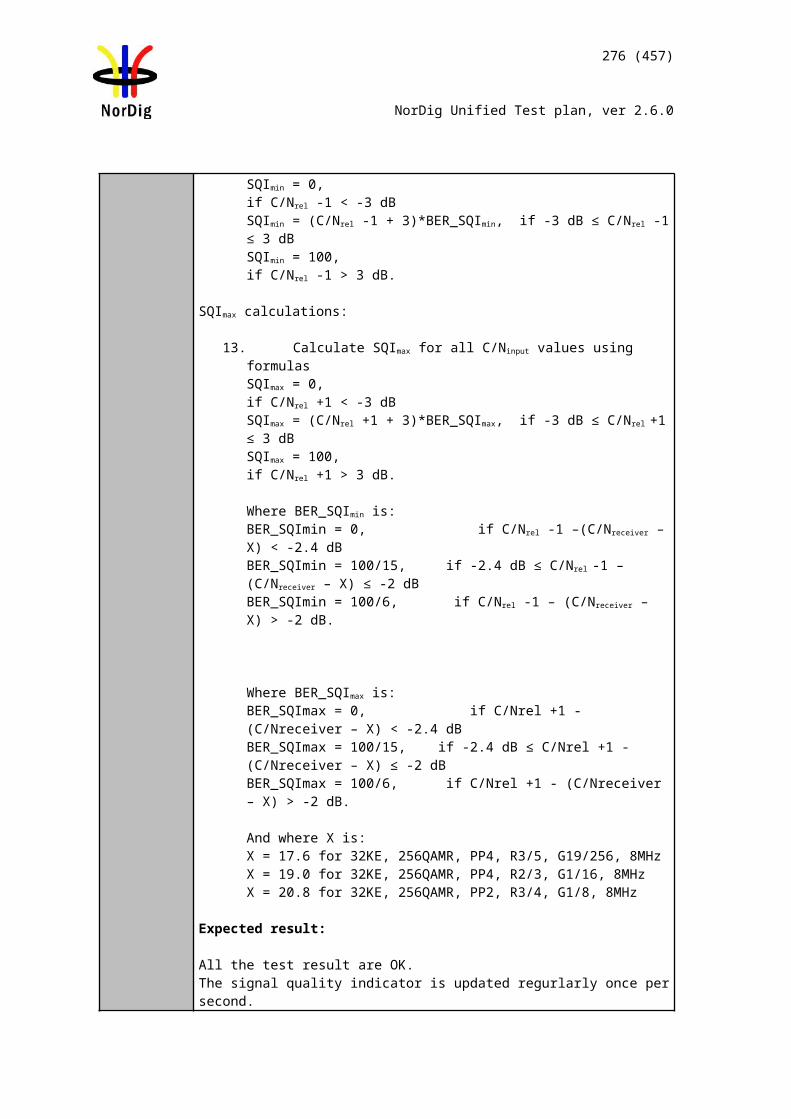
Audio decoder
MUX Exciter IRDTS Source
276 (457)
NorDig Unified Test plan, ver 2.6.0
Describe more specific faults and/or other information
Date Sign
Test Case Task 7:16 HE AAC: Requirements
Section NorDig Unified 6.2.3Requirement
NorDig IRDs supporting HE-AAC (and thereby also AAC-LC) shall be capable of:• decoding HE-AAC Version 1 at Level 2 at sampling rates of 48 kHz according to ETSITS 101 154 [29].• decoding, including downmixing HE-AAC Version 1 at Level 4 (multi-channel, up to5.1) at sampling rates of 48 kHz according to ETSI TS 101 154 [29], Annex C(downmix).• transcoding HE-AAC Version 1 at Level 4 (multi-channel, up to 5.1) at sampling rates of 48 kHz according to TS 101 154 [29], Annex H to AC-3 or DTS.
Nordig IRDs shall be able to skip bitstream elements that are not recognized, i.e. unknown Fill elements and Data Stream elements.
If NorDig IRD is supporting HE-AAC audio stream transcoding to AC-3 audio stream, it shall be done according to TS 102 366 [36]. Transcoding to AC-3 multichannel audio streams shall be at a fixed bit rate of 640 kbps.
If NorDig IRD is supporting HE-AAC audio stream transcoding to DTS audio stream, it shall be done according to TS 102 114 [33] at a fixed bit rate of 1,536 Mbps.
IRD Profile(s) Basic, IRD, FETest procedure Purpose of test:
To verify that the IRD supports HE AAC requirements.
Equipment:
The TS shall contain a service with HE AAC Level 2 @48kHz (mono,stereo) audio component with
relevant signaling. a service with HE AAC Level 4 @ 48kHz (multichannel)audio component with
relevant signaling.
Test procedure:
1. Connect the IRD to an audio receiver, e.g. Home Theater System with HDMI.2. Verify that service has a multichannel HE AAC audio available.3. In receiver menu, select MPEG stereo audio.4. Verify that HE AAC multichannel is decoded and downmixed to PCM stereo
bitstream for HDMI output and if supported for HDMI ARC.5. Verify the audio output level can be adjusted.6. In receiver menu, select multichannel audio.
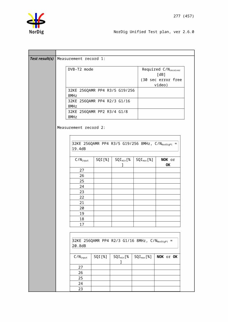
277 (457)
NorDig Unified Test plan, ver 2.6.0
7. Verify that HE AAC multichannel is trascoded to DTS or AC-3 bitstream for HDMI output.
8. Verify that service has a stereo HE AAC audio available.9. In receiver menu, select MPEGstereo audio.10. Verify that HE AAC stereo is decoded and downmixed to PCM stereo
bitstream for HDMI output and if supported for HDMI ARC.11. Verify the audio output level can be adjusted.12. In receiver menu, select multichannel audio.13. Verify that HE AAC stereo is transcoded to DTS or AC-3 bitstream for HDMI
output.
Expected result:
IRD supports decoding of HE AAC Level 2 and 4 @ 48 kHz and transcoding of it to AC-3 or DTS and supports down-mixing.
Test result(s)Feature NOK or OKDecoding of HE AAC L2 @48kHz Decoding of HE AAC L4 @48kHzTranscoding of HE AAC L4 @48kHz to AC-3 at 640kbpsTranscoding of HE AAC L4 @48kHz to DTS 1.536MbpsDown-mixing of HE AAC L4 @48kHz
Conformity OK Fault Major Minor, define fail reason in commentsComments If possible describe if fault can be fixed with software update: YES NO
Describe more specific faults and/or other information
Date Sign
Test Case Task 7:17 HE AAC: Analogue audio output
Section NorDig Unified 6.2.3.1Requirement The NorDig IRD with SCART and/or analogue outputs shall always have an audio
signal present on the analogue outputs (SCART and stereo out, see section 8.5 and to built-in loudspeakers (see note 1)) if any of the supported formats is received.
If the NorDig IRD has analogue stereo output(s), it shall be capable of decoding and downmixing the supported audio formats for the analogue outputs.
NorDig IRDs supporting HE-AAC (and thereby also AAC-LC) shall be capable of:• decoding HE-AAC Version 1 at Level 2 at sampling rates of 48 kHz according to ETSI TS 101 154 [29].• decoding, including downmixing HE-AAC Version 1 at Level 4 (multi-channel, up to 5.1) at sampling rates of 48 kHz according to ETSI TS 101 154 [29], Annex C (down-mix).
IRD Profile(s) Basic, IRD, FETest procedure Purpose of test:
To verify that receiver decodes HE AAC bitstream and the audio output level can be
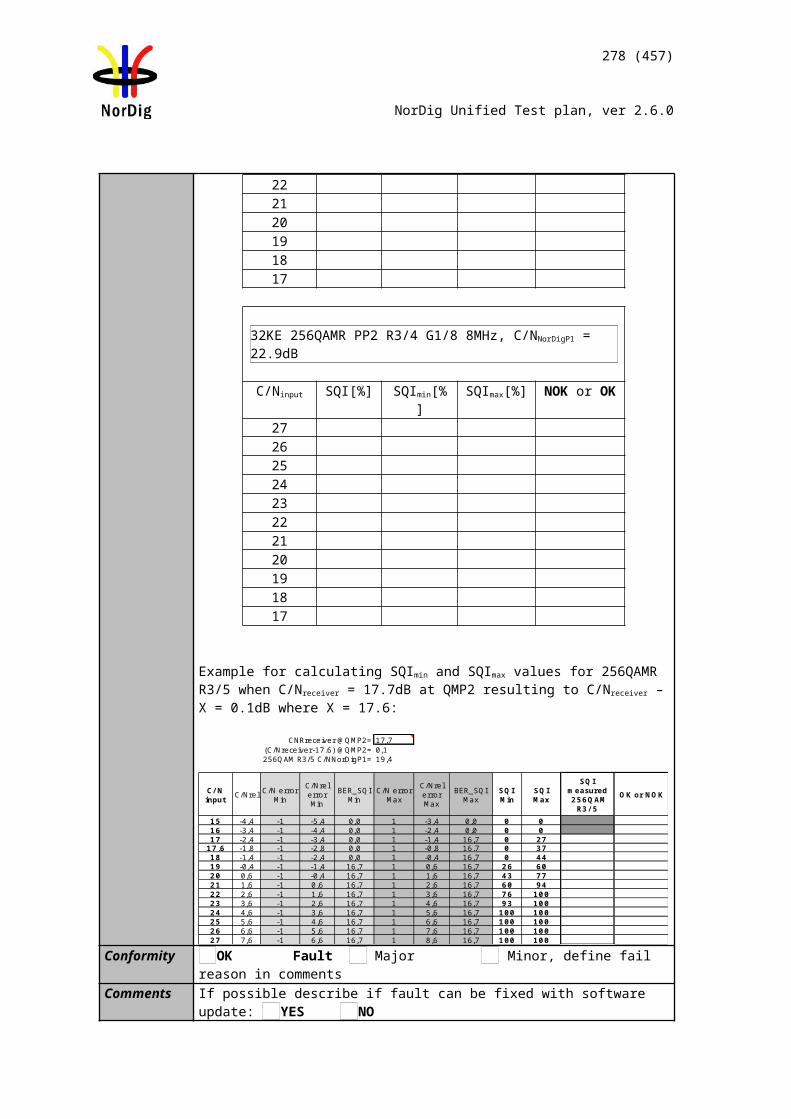
Source MUX Exciter DVB receiver
Monitor
278 (457)
NorDig Unified Test plan, ver 2.6.0
adjusted.
This test in only mandatory for STB or IDTV with SCART or analogue audio output interface.
Equipment:
A transport stream shall contain: a service with HE AAC Leve l2 @ 48kHz (stereo) audio component with
relevant signaling. a service with HE AAC Level 4 @ 48kHz (multichannel) audio component
with relevant signaling.
Test procedure:
1. Verify that services are available.2. In receiver menu, selectstereo audio.3. Select service with HE AAC Level2@48kHz (stereo).4. Verify that stereo audio is available at analog audio output.5. Verify the audio output level can be adjusted.6. Select service with HE AAC Level4@48kHz (multichannel) 7. Verify that HE AAC multichannel is downmixed to stereo at analog audio
output and HE AAC stereo is available at analog audio output.8. Verify the audio output level can be adjusted.9. In receiver menu, select multichannel audio.10. Verify that HE AAC multichannel is downmixed to stereo at analog audio
output output and HE AAC stereo is available at analog audio output.
Expected result:
IRD supports HE AAC stereo audio decoding to stereo audio and the audio output level can be adjusted. IRD supports HE AAC multichannel audio downmixing to stereo in analog audio output(s) and the audio output level can be adjusted.
Test result(s)Conformity OK Fault Major Minor, define fail reason in commentsComments If possible describe if fault can be fixed with software update: YES NO
Describe more specific faults and/or other information
Date Sign
Test Case Task 7:18 HE AAC: HDMI output and HDMI ARC interface
Section NorDig Unified 6.2.3.1Requirement NorDig IRDs supporting HE-AAC shall be capable of providing the following formats
on the HDMI output connector from a HE-AAC bitstream (see chapter 16 for factory
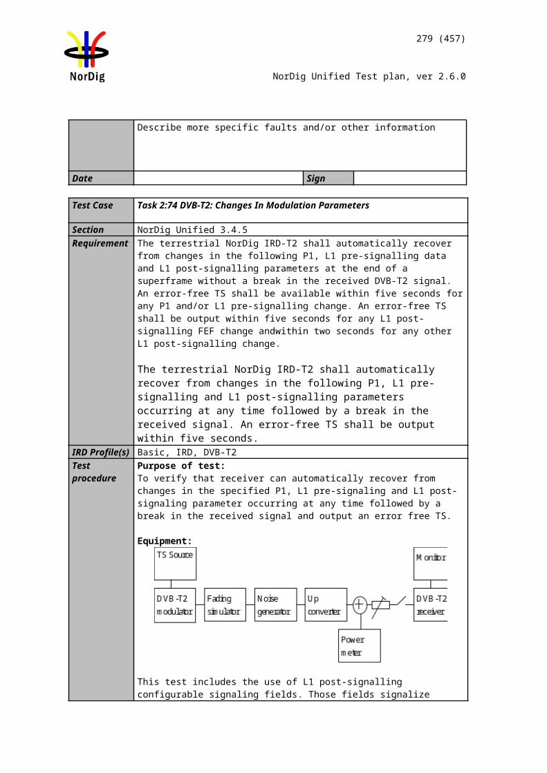
MPEG-2 source
MUX Exciter DVB receiver
HDMI receiver
Monitor
279 (457)
NorDig Unified Test plan, ver 2.6.0
default settings):• Transcoded to AC-3 or DTS bitstream.• Decoded and downmixed (if > 2 channels) to PCM stereo bitstream
IRD Profile(s) Basic, IRD, FETest procedure Purpose of test:
To verify that receiver decodes/transcodes and passes-through HE AAC bitstream.When HE AAC bitstream is decoded and transcoded the audio output level can be adjusted.
This test in only relevant for IRD with HDMI output and HDMI ARC.
Equipment:
A transport stream contains: a service with HE AAC Level2 @48kHz (mono,stereo)audio component with
relevant signaling. a service with HE AAC Level 4 @48kHz (multichannel)audio component with
relevant signaling.
Test procedure:
1. Connect the IRD to HDMI receiver e.g. Home Theater System with HDMI.2. Verify that services are available.3. In receiver menu, select stereo audio.4. Select service with HE AAC Level2@48kHz (stereo).5. Verify that HE AAC stereo is transcoded to PCM stereo audio bitstream at
HDMI output and HDMI ARC.6. Verify the audio output level can be adjusted.7. Select service with HE AAC Level4@48kHz (multichannel) 8. Verify that HE AAC multichannel is downmixed to PCM stereo at HDMI
output and HDMI ARC.9. Verify the audio output level can be adjusted.10. In receiver menu, select multichannel audio.11. Verify that HE AAC multichannel is transcoded to AC-3 or DTS multichannel
at HDMI output and HDMI ARC
Expected result:
IRD supports HE AAC stereo audio decoding to PCM stereo bitstream at its HDMI output and HDMI ARC when stereo audio is selected. The audio output level can be adjusted. IRD supports HE AAC multichannel audio transcoding to AC-3 and/or DTS at its HDMI output and HDMI ARC when multichannel is selected.
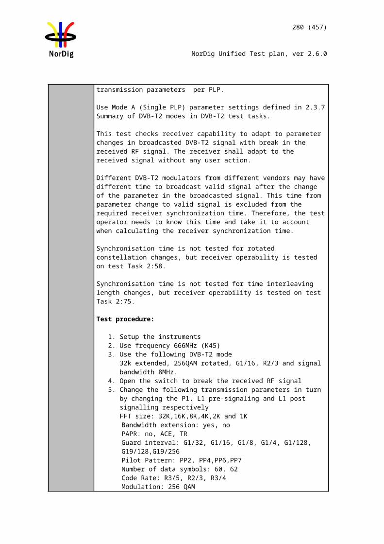
MPEG-2 source
MUX Exciter DVB receiver
S/PDIF receiver
Monitor
280 (457)
NorDig Unified Test plan, ver 2.6.0
Test result(s)Conformity OK Fault Major Minor, define fail reason in commentsComments If possible describe if fault can be fixed with software update: YES NO
Describe more specific faults and/or other information
Date Sign
Test Case Task 7:19 HE AAC: S/PDIF output interface
Section NorDig Unified 6.2.3.1Requirement The NorDig IRD supporting HE-AAC and including an S/PDIF output shall be capable
of providing the following formats on the S/PDIF connector from a HE-AAC bitstream:
• Decoded and downmixed (if > 2 channels) to PCM stereo bitstream• Transcoded to AC-3 or DTS bitstream
IRD Profile(s) Basic, IRD, FETest procedure Purpose of test:
To verify that receiver decodes/transcodes and passes-through HE AAC bitstream.
This test in only relevant for IRD with S/PDIFoutput.
Equipment:
A transport stream contains: a service with HE AAC Level 2 @48kHz (mono,stereo)audio component with
relevant signaling. a service with HE AAC Level 4 @48kHz (multichannel)audio component with
relevant signaling.
Test procedure:
1. Connect the IRD to S/PDIF receiver e.g. Home Theater System with S/PDIF.2. Verify that servicesare available.3. In receiver menu, select stereo audio.4. Verify that HE AAC multichannel is transcoded to PCM stereo at S/PDIF
output and HE AAC stereo is transcoded to PCM stereo at S/PDIF output.5. In receiver menu, select multichannel audio.6. Verify that HE AAC multichannel is transcoded to AC-3 or DTS multichannel
at S/PDIF output and HE-AAC stereo is transcoded to AC-3 2.0 or PCM stereo at S/PDIF output.
281 (457)
NorDig Unified Test plan, ver 2.6.0
Expected result:
IRD supports HE AAC stereo audio decoding to PCM stereo when stereo is selected at its S/P DIF output. IRD supports HE AAC multichannel transcode to AC-3 and/or DTS at its S/PDIF output when multichannel is selected.
Test result(s)Conformity OK Fault Major Minor, define fail reason in commentsComments If possible describe if fault can be fixed with software update: YES NO
Describe more specific faults and/or other information
Date Sign
Test Case Task 7:20 HE AAC: Metadata
Section NorDig Unified 6.2.3.2Requirement
The NorDig IRD supporting HE-AAC shall support the use of the following MPEG-4 AAC metadata embedded in the audio stream when decoding HE-AAC and transcoding HE-AAC multi-channel to AC-3 or DTS:• Program Reference Level according to ISO/IEC 14496-3 [57] (prog_ref_level)• Downmix Parameters according to "Transmission of MPEG4 Ancillary Data" part ofDVB specification ETSI TS 101 154 [29] (center_mix_level, surround_mix_level)• Dynamic Range Control (DRC) according to ISO/IEC 14496-3 [57] (dyn_rng_sgn,dyn_rng_ctl)• Heavy Compression according to ETSI TS 101 154 Annex C.5.2.5 (compression_on,
• compression_value)
IRD Profile(s) Basic, IRD, FE
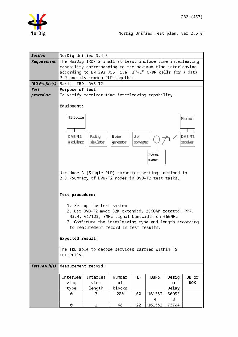
MUX Exciter IRDTS Source
282 (457)
NorDig Unified Test plan, ver 2.6.0
Test procedure Purpose of test:To verify that the IRD supports HE AAC metadata.
Equipment:
The TS containing: A service with program reference level (prog_ref_level) A service with downmix parameters (center_mix_level, surround_mix_level) A service with dynamic range control (dyn_rng_sgn, dyn_rng_ctl) A service with heavy compression (compression_on, compression_value)
Test procedure:
1. Connect the IRD under the test to an amplifier that supports the metadata decoding
2. Play the stream and tune the IRD to the service that contains the metadata3. Check that the IRD transforms the HE AAC metadata in the stream to the
matching Dolby metadata. Note: A Dolby Reference decoder can be used to read the Dolby metadata values (if IRD transcodes to AC-3).
NOTE: For IRD´s that transcode to DTS, metadata might be more difficult to verify. DTS Reference decoder can be used
Expected result: IRD shall support HE AAC metadata according to requirement.
Test result(s)Conformity OK Fault Major Minor, define fail reason in commentsComments If possible describe if fault can be fixed with software update: YES NO
Describe more specific faults and/or other information
Date Sign
Test Case Task 7:21 Audio prioritizing - Audio language support
Section NorDig Unified 6.5, 6.5.1.1Requirement The user shall be able to select storable preferences for primary and secondary audio
language. If an audio-stream according to the primary audio language preference is not associated with the chosen service the NorDig IRD shall automatically choose the audio stream according to the secondary audio language preference, if present. In addition the user shall be able to manually select between all audio-streams that are associated with the active service.
For the selection of audio language (see Table 6.1 and Table 6.2), the NorDig IRD shall use the ISO 639 lanaguage code from the supplementary audio descriptor (1) and/or the ISO 639 language descriptor.
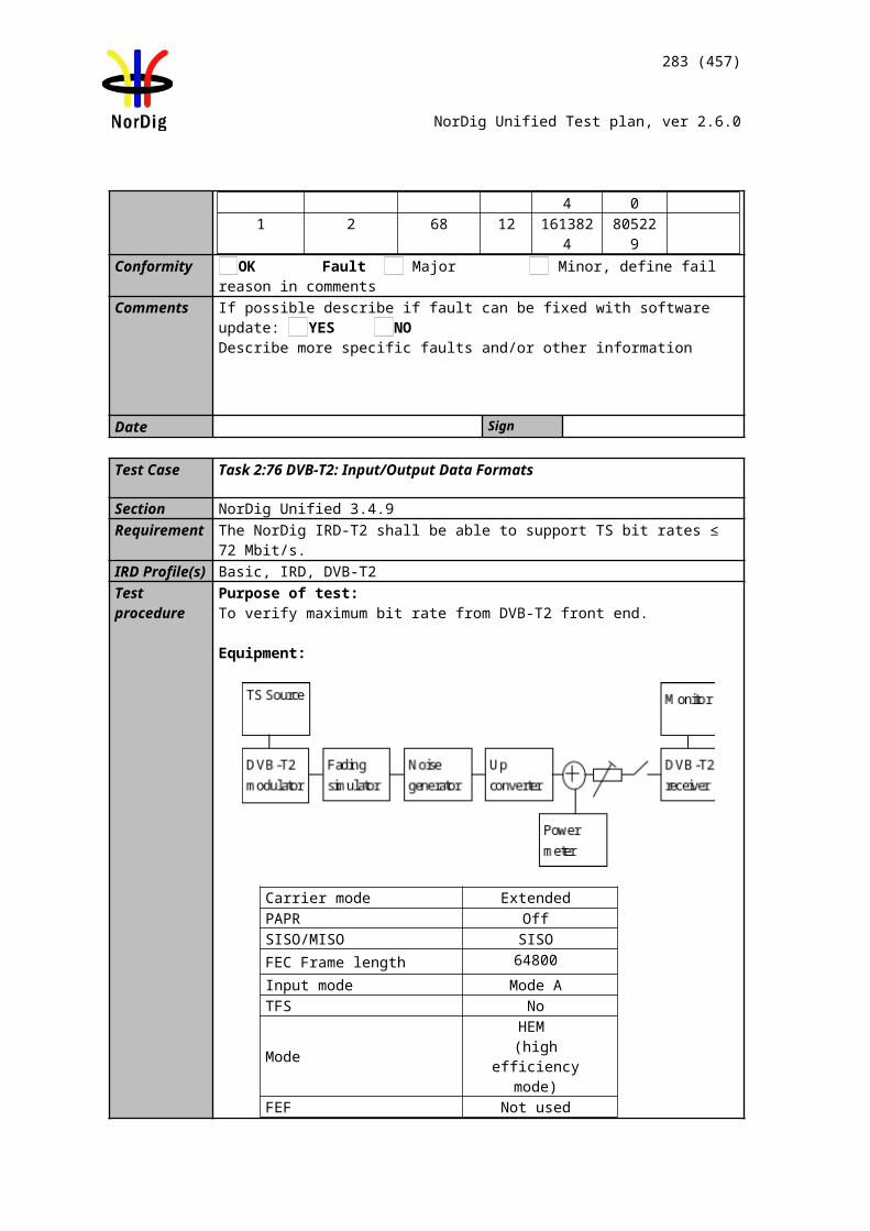
283 (457)
NorDig Unified Test plan, ver 2.6.0
IRD Profile(s) Basic, IRD, FETest procedure Purpose of test:
To verify the support for primary and secondary audio language.
Equipment:
Transport stream containing at least one service with two audio languages.Suitable languages are Swedish, Finnish, Norwegian, Danish, Icelandic, Sami, Irish/Gaelic and English.
Test procedure:
1. Verify a service with two different audio components is broadcasted dedicated for test of Nordic languages
2. Verify the audio components are signaled correctly. 3. Verify it is possible to select and setup primary and secondary audio language
in the receiver setup.4. Verify the receiver selects the correct audio for primary language.5. Drop the audio component selected as primary audio language in receiver.6. Verify the receiver selects correct audio component, i.e. secondary audio
language.
Expected result: It shall be possible to select primary and secondary language. If the selected primary language is not broadcasted, the selected secondary audio language shall be selected automatically.
Test result(s)Conformity OK Fault Major Minor, define fail reason in commentsComments If possible describe if fault can be fixed with software update: YES NO
Describe more specific faults and/or other information
Date Sign
Test Case Task 7:22 Audio Prioritising – audio format and stream type
Section NorDig Unified 6.5Requirement The NorDig IRD shall be able to select audio stream according to user
selections, these settings should be stored in the IRD´s memory separately for each service. If manually selected audio is not able to be stored in the IRD´s memory per service, a global setting should be made possible to set manual prioritisation of stream type for all services. The priority for the selected audiosource shall be based on the user selections and audio stream shall be selected according to the priority list in table table 6.1 below. If the user selections are not matching with the audio streams, the NorDig IRD shall always select one of the audio streams which closest suites with the user selections and will hereby provide audio to end-user.
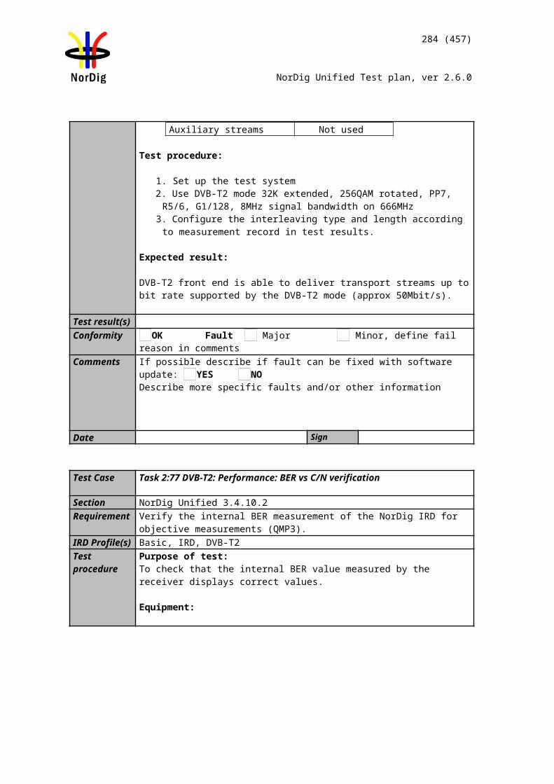
Audio decoder
MUX Exciter STBTS Source
284 (457)
NorDig Unified Test plan, ver 2.6.0
The user shall be able to select multi-channel audio for the digital outputs, when the outputs are equipped for multichannel audio.If multichannel mode is selected and if both multichannel and stereo streams are available for the selected language and audio type, the NorDig IRD shall use the multichannel audio stream to provide downmixed audio in analog audio output(s), if applicable, and suitable digital bitstream format in digital audio output(s) as e.g. in examples in Annex G (Example table when more than one audio codec is received).If stereo mode is selected and if both multichannel and stereo streams are available for the selected language and audio type, the NorDig IRD shall use the stereo audio source to provide audio in analog audio output(s), if applicable, and PCM stereo in digital audio output(s) as e.g. in examples in Annex G (Guidelines for NorDig IRD audio selection: “Example table when morethan one audio stream is received”).
IRD Profile(s) Basic, IRD, FETest procedure Purpose of test:
To verify the audio priority selection and output audio format.
Test Equipment:
Transport stream containing services with audio components (same language and audio type) listed in table below in test results.
Suitable languages are Swedish, Finnish, Norwegian, Danish, Icelandic, Sami, Irish/Gaelic and English.
Audio type is “normal”.
Audio format and stream type shall be signaled in AAC_descriptor, AC-3_descriptor or E-AC-3_descriptor according to following:
1) the AAC_type field in the AAC_descriptor for AAC audio,2) the number of channels flags in the AC-3 descriptor and Enhanced AC-
3 descriptor for AC-3 and E-AC-3.Correct signaling is broadcasted depending of the audio format and stream type in test results table. IRD is assumed to prioritise audio format and stream type according to list above.Test procedure:
1. Setup the system2. Verify that the audio selection is done correctly according the input formats in
table below in test results3. Repeat test with all input format in table below4. Fill in test results
Expected result: The IRD shall select the audio format and stream type correctly.
Test result(s)
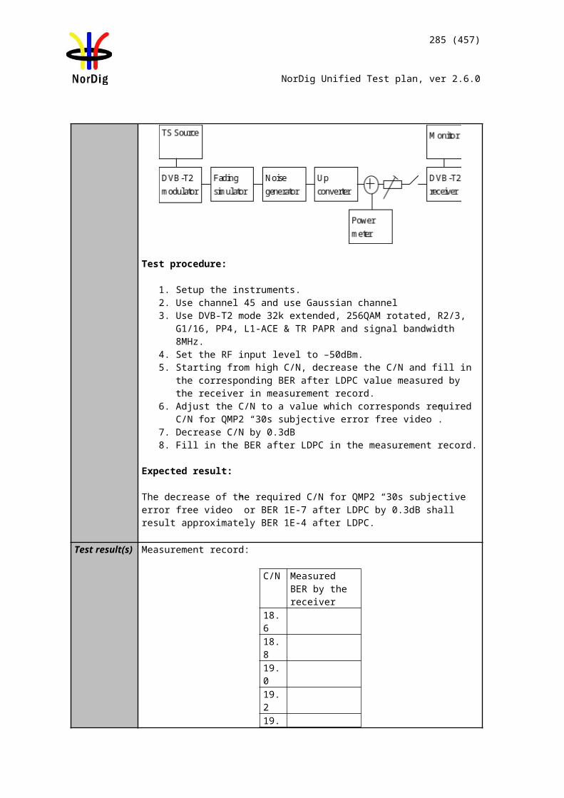
285 (457)
NorDig Unified Test plan, ver 2.6.0
Available inputs formats (same
language and audio type)
Output on analog interface or integrated loudspeakers
OK/NOK
When Stereo is selected (default)
When Multichannel is selected
MPEG1 layer II &AC-3
Decoded from MPEG1 LII
Downmixed from AC-3
MPEG1 layer II &E-AC-3
Decoded from MPEG1 LII
Downmixed fromE-AC-3
HE AAC stereo &HE AAC multichannel
Decoded from HE AAC stereo
Downmixed from HE AAC multichannel
HE AAC stereo & AC-3 multichannel
Decoded from HE AAC stereo
Downmixed from AC-3 multichannel
Available inputs formats (same
language and audio type)
Output on S/PDIF OK/NOKWhen Stereo is
selected (default)When Multichannel
is selected
MPEG1 layer II &AC-3
PCM (from MPEG1 LII)
AC-3
MPEG1 layer II &E-AC-3
PCM (from MPEG1 LII)
Transcoded toAC-3 (from E-AC-3)
HE AAC stereo &HE AAC multichannel
PCM (from HE AAC stereo)
Transcoded toAC-3, or
DTS (from HE AAC multichannel)
HE AAC stereo & AC-3 multichannel
PCM (from HE AAC stereo)
AC-3
Available inputs formats (same language and audio type)
Output on HDMI OK/NOKWhen Stereo is
selected (default)When Multichannel
is selected
MPEG1 layer II &AC-3 multichannel
PCM (from MPEG1 LII)
AC-3
MPEG1 layer II &E-AC-3 multichannel
PCM (from MPEG1 LII)
AC-3 1)
MPEG1 layer II &E-AC-3
PCM (from MPEG1 LII)
E-AC-3
HE AAC stereo &HE AAC multichannel
PCM (from HE AAC stereo)
HE AAC multichannel
HE AAC stereo &HE AAC multichannel
PCM (from HE AAC stereo)
Transcoded 2) to AC-3, or
DTS
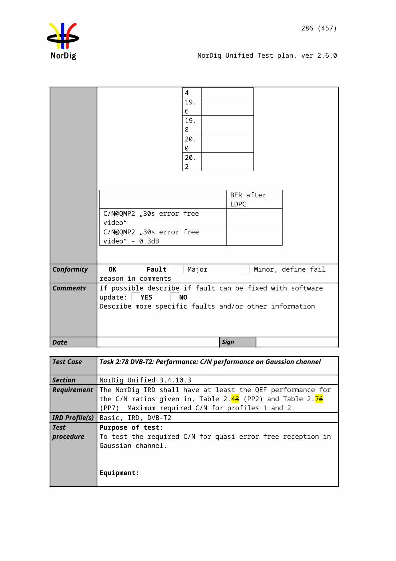
TS source MUX Exciter DVB receiver
286 (457)
NorDig Unified Test plan, ver 2.6.0
HE AAC stereo & AC-3 multichannel
PCM (from HE AAC stereo)
AC-3
1) transcoded to AC-3 if E-AC-3 is not supported by receiving device2) transcoded to AC-3 or DTS if HE AAC not supported by receiving device
1.Conformity OK Fault Major Minor, define fail reason in commentsComments If possible describe if fault can be fixed with software update: YES NO escribe
more specific faults and/or other information
Date Sign
Test Case Task 7:23 Audio Prioritising – audio type
Section NorDig Unified 6.5Requirement The NorDig IRD shall be able to select audio stream according to user
selections, these settings should be stored in the IRD´s memory separately for each service. If manually selected audio is not able to be stored in the IRD´s memory per service, a global setting should be made possible to set manual prioritisation of stream type for all services. The priority for the selected audiosource shall be based on the user selections and audio stream shall be selected according to the priority list in table table 6.1 below. If the user selections are not matching with the audio streams, the NorDig IRD shall always select one of the audio streams which closest suites with the user selections and will hereby provide audio to end-user.
IRD Profile(s) Basic, IRD, FETest procedure Purpose of test:
Verify that IRD selects normal/undefined (0x00) audio component by default.
Equipment:
The TS must contain two services with several audio components for the same language, audio formats and stream type but different audio types.
Suitable languages are Swedish, Finnish, Norwegian, Danish, Icelandic, Sami, Irish/Gaelic and English.
Audio type is signaled in PMT in one or all of the following descriptors:1) Supplementary_audio_descriptor for any stream type.2) AAC_descriptor for AAC audio.3) AC-3 descriptor for AC-3 audio.4) Enhanced AC-3 descriptor for E-AC-3 audio.5) ISO639_descriptor for any stream type.
IRD is assumed to prioritise the audio type signalization information in that order.
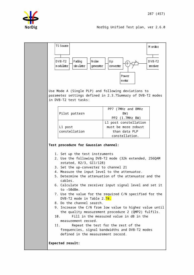
287 (457)
NorDig Unified Test plan, ver 2.6.0
Audio format is stereo.
Stream type for all audio components is either MPEG-4 HE.AAC version 1 or E-AC-3 including metadata corresponding audio_type.
Service1 Service2 FrequencyMUXTS_id 1Network_id 1ON_id 1)
SID 1100S_name Test11PMT PID 1100V PID 1109A PID 1108
ISO639_language_code 2) Audio_type hearing impaired
A PID 1107 ISO639_language_code 2) Audio_type visual impaired commentary
A PID 1106 ISO639_language_code 2) Audio_type Normal/Undef
LCD 1 visible
SID 1200S_name Test12PMT PID 1200V PID 1209A PID 1208
ISO639_language_code 2) Audio_type hearing impaired
A PID 1207 ISO639_language_code 2) Audio_type visual impaired commentary
A PID 1206 ISO639_language_code 2) Audio_type Normal/Undef
LCD 2 visible
Can be chosen depending of the distribution media
1) ON_id (Original_network_id) can be chosen in range 0x0001-0xfe00 (operational network) and it shall be same for both muxes.
2) Language must the same for all audio components and it can be one of the swe/fin/nor/ice/dan/smi/gle/iri/eng/und
Test procedure:1. Verify the receiver selects audio component which has normal/undefined audio
by default2. Verify user is able to select different audio components. 3. Verify that the user is able to store selected audio component in the IRD´s non-
volatile memory, or can be set by changing the priority defined in list in table 6.1.
4. Put IRD into standby mode and unplug the power cord5. Turn on the IRD6. Zap to different service and verify that the IRD is selecting wanted audio.
Expected result:
IRD selects the audio component that is signalled as Normal/Undefined (0x00) by default when several audio components with the same language code, audio format and stream type but different audio type are available within one service.
The user shall also be able to select between the different audio components. The user should also be able to store the selected audio component prioristation to non-volatile memory.
Test result(s)
Conformity OK Fault Major Minor, define fail reason in commentsComments If possible describe if fault can be fixed with software update: YES NO
Describe more specific faults and/or other information
Date Sign
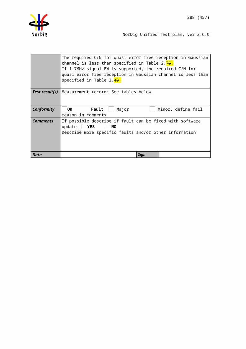
TS source MUX Exciter DVB receiver
288 (457)
NorDig Unified Test plan, ver 2.6.0
Test Case Task 7:24 Audio Prioritising – audio format signaling missing
Section NorDig Unified 6.5.1.3Requirement For the selection of audio format (mono, stereo or multichannel, see Table 6.1
[1] and Table 6.2 [1]), the NorDig IRD shall use:
- the AAC_type field in the AAC_descriptor for AAC audio,- the number of channels flags in the AC-3 descriptor and Enhanced AC-3 descriptor for AC-3 and E-AC-3.
In any case where, for some reason, this information is not carried in the PMT for a particular audio stream, then the IRD shall prioritise based on the assumption that audio stream contains “normal” stereo content.
IRD Profile(s) Basic, IRD, FETest procedure Purpose of test:
Verify which audio component the IRD selects when no additional audio format signalization is added to audio component.
Equipment:
The TS shall contain two services with two audio components. The PMTs shall contain the elementary streams with appropriate stream_types.All audio tracks shall be signaled with a same language and audio_type (0x0) in ISO_639_language_descriptor.No other descriptors shall be signaled for the audio streams.
Service1 Service2 FrequencyMUXTS_id 1Network_id 1ON_id 1)
SID 1100S_name Test11PMT PID 1100V PID 1109A PID 1108 (HE AAC L4)A PID 1107 (MPEG1 LII stereo)LCD 1 visible
SID 1200S_name Test12PMT PID 1200V PID 1209A PID 1208 (AC-3 multichannel)A PID 1207 (MPEG1 LII stereo)LCD 2 visible
Can be chosen depending of the distribution media
1) ON_id (Original_network_id) can be chosen in range 0x0001-0xfe00 (operational network) and it shall be same for both muxes.
Test procedure:1. Configure the IRD to select ‘normal’ stereo audio.2. Zap through the services in the stream.3. Verify that the IRD selects the MPEG1-LII audio component and audio is played
out correctly.4. Configure the IRD to select ‘normal’ multichannel audio.5. Zap through the services in the stream.6. Verify that the IRD selects the advanced audio component and audio is played
out correctly.
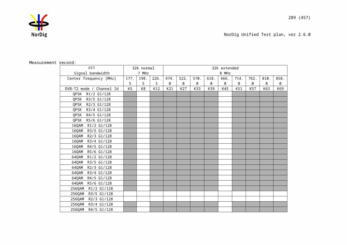
289 (457)
NorDig Unified Test plan, ver 2.6.0
Expected result:
IRD selects the audio component that is signalled as Normal/Undefined (0x00) by default when several audio components without signaling is available within one service.
Test result(s)
Conformity OK Fault Major Minor, define fail reason in commentsComments If possible describe if fault can be fixed with software update: YES NO
Describe more specific faults and/or other information
Date Sign
Test Case Task 7:25 Audio video synchronization
Section NorDig Unified 6.7.1Requirement The NorDig IRDs shall not introduce more than ± 5 ms of relative delay between the
audio and video components on the primary output (1) and not more than ± 25 ms between the primary video output and a secondary audio output. (2)The relative delay between the audio and video components shall be continously synchronized.If the NorDig IRD, as a part of an integrated digital TV set (IDTV) has an audio output, the audio shall be in sync with the video display.Where audio leaves the IRD in an encoded form (such as in IEC61937 [45] outputs and/or HDMI outputs and/or HDMI Audio Return Channel (ARC)), the IRD shall compensate for the decoding latency of the selected audio format, as specified for the relevant reference decoder for the selected format (e.g AC-3), such that the output of the reference decoder would be ± 5 ms with respect to the decoded video. This applies for all audio systems that the IRD supports.
IRD Profile(s) Basic, IRD, FETest procedure Purpose of test:
To verify that the relative time delay difference between video and audio on primary output satisfies the specification.
Mandatory for IDTVs with integrated loudspeakers.
Relevant for STB and IDTVs with audio output interfaces for analog audio,HDMI output and HDMI ARC.
Equipment:
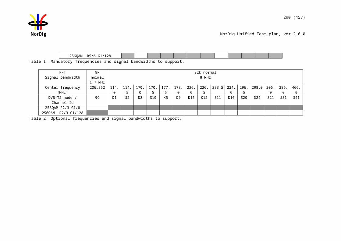
Source MUX Exciter
Reference device for video and audio inspection
Reference device for audio listening
Video/audio synchronisation measurement device
IDTV
STB
290 (457)
NorDig Unified Test plan, ver 2.6.0
Transport stream containing: a ‘Bounce’ video signal (fully black and white pictures). The audio (sound bursts) is synchronized with the video.
Test procedure:
If the IRD is iDTV:
1. Subjectively verify the video content in the integrated display is in synchronization with the audio content on the integrated loudspeakers.
2. If any doubt is arisen for the synchronisation accuracy, measure the synchronization with the dedicated measurement equipment.
3. If the IDTV supports analog audio output or digital audio output on HDMI output, HDMI ARC or S/PDIF, connect a receiving reference device to such an output interface.
4. Verify subjectively if the audio on the reference device is in synchronization with the video displayed on the IDTV.
5. If any doubt is arisen for the synchronisation accuracy, measure the synchronization with the dedicated measurement equipment.
If the IRD is STB:1. Connect a receiving reference device to primary HDMI output interface. 2. Verify subjectively if the audio on the reference device is in synchronization
with the video displayed on the reference device.3. If any doubt is arisen for the synchronisation accuracy, measure the
synchronization with the dedicated measurement equipment.4. If the STB supports analog audio output or digital audio output on S/PDIF,
connect a receiving reference device to such an output interface.5. Verify subjectively if the audio on the reference device is in synchronization
with the video displayed on the reference device.
Expected result:
If the IRD is an iDTV the relative delay between video on integrated display and audio on integrated
loudspeakers is less than ±5 ms. the relative delay between video on integrated display and audio on the analog
audio output or digital audio outputs HDMI output, HDMI ARC and S/PDIF is less than ±5 ms.
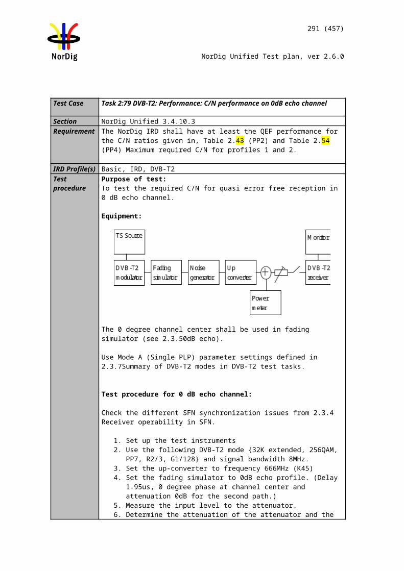
Audio decoder
MUX Exciter STBTS Source
Display
291 (457)
NorDig Unified Test plan, ver 2.6.0
If the IRD is an STB, the relative delay between video and audio on HDMI output is less than ±5 ms. the relative delay between video on reference display and audio on analog
audio output or digital audio output S/PDIF is less than ±5 ms.
The secondary display output is not measured.
Test result(s)Conformity OK Fault Major Minor, define fail reason in commentsComments If possible describe if fault can be fixed with software update: YES NO
Describe more specific faults and/or other information
Date Sign
Test Case Task 7:26 Adjustement of Video/audio-delay
Section NorDig Unified 6.7.1Requirement The NorDig IRD shall support the possibility to adjust the audio-delay on the HDMI and
S/PDIF output (if available) up to 250 ms and it should be adjustable in 5 ms steps, as the IRD may have several different user set-ups, resulting in different a/v delays; e.g. the IRD may be connected to several types of external audio-amplifiers and the IRD may be connected to several types of external screens.
IRD Profile(s) Basic, IRD, FETest procedure Purpose of test:
To verify that the IRD has settings for video/audio delay.This requirement is only applicable to IRDs that are not part of an IDTV.
Equipment:
Test procedure:
1. Verify the IRD has a setting to setup video/audio delay up to 250ms.2. Verify the setting has effect in delay between video and audio.
Expected result:
It is possible to change static delay between video and audio decoding and it has effect.
Test result(s)Conformity OK Fault Major Minor, define fail reason in commentsComments If possible describe if fault can be fixed with software update: YES NO
Describe more specific faults and/or other information
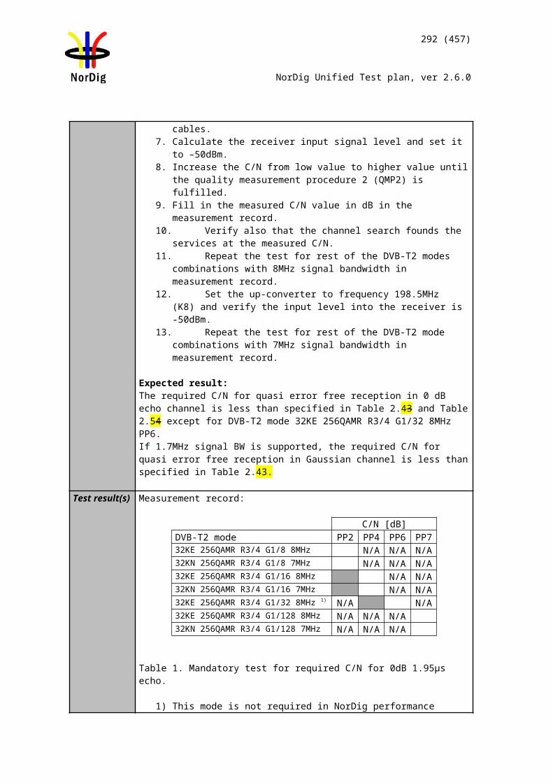
MUX Exciter IRDTS Source
292 (457)
NorDig Unified Test plan, ver 2.6.0
Date Sign
Test Case Task 7:27 Audio handling when changing service or audio format
Section NorDig Unified 6.9Requirement The NorDig IRD should gracefully handle change of service or audio format at the
audio outputs without significant disturbances to the end user.
IRD Profile(s) Basic, IRD, FETest procedure Purpose of test:
To verify that the IRD handles audio format changes in zapping and audio format change.
Equipment:
The TS shall contain several services, but at least following services with following components
a HE AAC Level2 @48kHz and/or E-AC-3 (stereo)audio component with relevant signaling.
a HE AAC Level 4 @48kHz and/or E-AC-3 (multichannel)audio component with relevant signaling.
a MPEG-1 Layer II (stereo) with relevant signaling.
Test procedure:
1. Zap to different services2. Verify the IRD is able to settle to different audio formats 3. Decide if the format settling could disturb end-user.
Expected result:
Audio format change is handled gracefully.
Audio handling does not disturb the end-user.
Test result(s)Conformity OK Fault Major Minor, define fail reason in commentsComments If possible describe if fault can be fixed with software update: YES NO
Describe more specific faults and/or other information
Date Sign
Test Case Task 7:28 Dynamic changes in audio components
MPEG-2 source
MUX Exciter DVB receiver
293 (457)
NorDig Unified Test plan, ver 2.6.0
Section NorDig Unified 6.9Requirement The NorDig IRD shall be able to handle dynamic changes of audio
component(s) (PID/PIDs) in a service. The IRD shall automatically identify if an audio component is added or removed between two programme events in the same service). The NorDig IRD should gracefully handle change of service or audio format at the audio outputs without significant disturbances to the end user.
The NorDig IRD shall handle the dynamic changes after change of selected service ("zapping") or dynamic PMT update (i.e. shall not require to re-install services) and shall be able to handle the following dynamic changes without user interaction and start decoding within one second after reception of change;• change of the audio codec, (for example change from MPEG-1 Layer II into AC-3)• change of ISO 639-2 [72] language for an audio component.
-
IRD Profile(s) Basic, IRD, FETest procedure Purpose of test:
To verify the IRD is able to handle dynamic changes of audio components in transmission.
- change of number of audio channels within same audio codec (eg. AC-3 2.0 to AC-3 5.1 and vice versa.- change of bitrate for an audio component (eg. MPEG1-L2 bitrate from 192 kbps to 160 kbps)- change of audio PID value (any codec)- change from dual-channel audio into stereo audio and vice versa- removal of selected audio component and using the next preferred one- addition of one audio component with higher preferred user setting- change of the audio codec (eg. from MPEG1-L2 to AC-3- change of ISO 639-2 language for an audio component
Equipment:
MPEG-2 source must have capability to support dynamic changes in audio components within service(s).In case of dual-channel audiothe first language_descriptor definition corresponds physical left channel and second language_descriptor definition corresponds physical right channel.
Test procedure:
1. Use MPEG-2 source to generate dynamic changes in audio components as listed in test results
2. Fill in the test results.
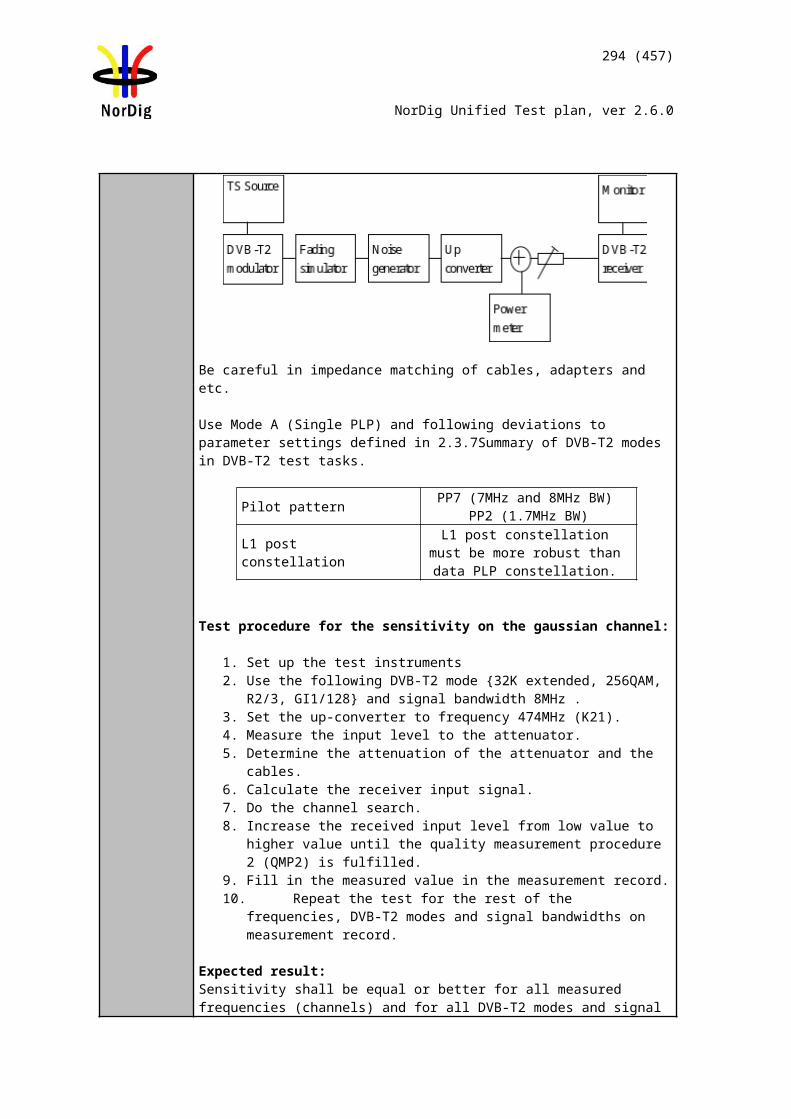
294 (457)
NorDig Unified Test plan, ver 2.6.0
Expected result:
IRD is able to handle dynamic changes in audio components.
Test result(s)NOK or OK
Change of number of audio channels within same audio codec (eg. AC-3 2.0 to AC-3 5.1 and vice versa.Change of bitrate for an audio component (eg. MPEG1-L2 bitrate from 192 kbps to 160 kbps)Change of audio PID value (any codec)Change from dual-channel audio into stereo audio and vice versaRemoval of selected audio component and using the next preferred oneAddition of one audio component with higher preferred user settingChange of the audio codec (eg. from MPEG1-L2 to AC-3Change of ISO 639-2 language for an audio component
Conformity OK Fault Major Minor, define fail reason in comments
Comments If possible describe if fault can be fixed with software update: YES NODescribe more specific faults and/or other information
Date Sign
Test Case Task 7:29 Audio descriptors
Section NorDig Unified 6.9Requirement The NorDig IRD shall be able to read the audio information contained in the DVB_SI
stream_content and component_type of the component descriptor as defined in EN 300 468 [16], see also chapter 12 and section 13.3.2. The NorDig IRD should be able to present the audio information, including the descriptors for audio description for the visually impaired and audio for the hard of hearing, contained in the component descriptor to the user for information and selection purposes.
IRD Profile(s) Basic, IRD, FETest procedure
The IRD manufacturer shall describe the used test procedure and the used test setup.
Test result(s) The IRD manufacturer shall describe the used test procedure and the used test setup.
Conformity OK Fault Major Minor, define fail reason in commentsComments If possible describe if fault can be fixed with software update: YES NO
Describe more specific faults and/or other information
Date Sign
295 (457)
NorDig Unified Test plan, ver 2.6.0
Test Case Task 7:30 Clean audio
Section NorDig Unified 6.10Requirement The NorDig IRD should support the “Clean Audio” concept by implementing
an easy way to adjust the balance between the centre channel and other channels in the audio stream before making a stereo down-mix.If implemented, clean audio shall be compliant to ETSI TS 101 154 [29].
IRD Profile(s) Basic, IRD, FETest procedure
TBD
Test result(s)Conformity OK Fault Major Minor, define fail reason in commentsComments If possible describe if fault can be fixed with software update: YES NO
Describe more specific faults and/or other information
Date Sign
Test Case Task 7:31 Supplementary audio
Section NorDig Unified 6.11Requirement The Nordig IRD audio decoder shall (1) be capable of supporting ‘visual impaired’
Supplementary audio (SA) services, as defined in ETS TS 101 154 [29] (however, control of pan and fade is optional).The NorDig IRD shall (1) support both Broadcast mixed and Receiver mixed Supplementary Audio.The NorDig IRD shall (1) have user selection of audio preferences for ‘normal’ and‘Supplementary’ audio and which is a fixed setting (i.e. remain when changing service and when re-starting the IRD).The user preference settings for enabled/disable default Supplementary audio shall (1) be common for Broadcast mixed (2) and Receiver mixed alternatives.
IRD Profile(s) Basic, IRD, FETest procedure Purpose of test:
To verify the IRD handles supplementary audio for narrator and spoken subtitling like of audio streams.Equipment:
A TS containing several services with several audio components for broadcast and receiver mixing.
Supplementary_audio_descriptor is signalled for all audio components according to content definition below.
The normal and supplementary audio for receiving mixing within a service are encoded as MPEG-1 Layer II, HE-AAC and E-AC-3 depending of which audio codecs are supported by the IRD. The audio streams sampling rate must be the same and the audio streams are separated to two different PIDs.
TS Source MUX ExciterDVB
Receiver
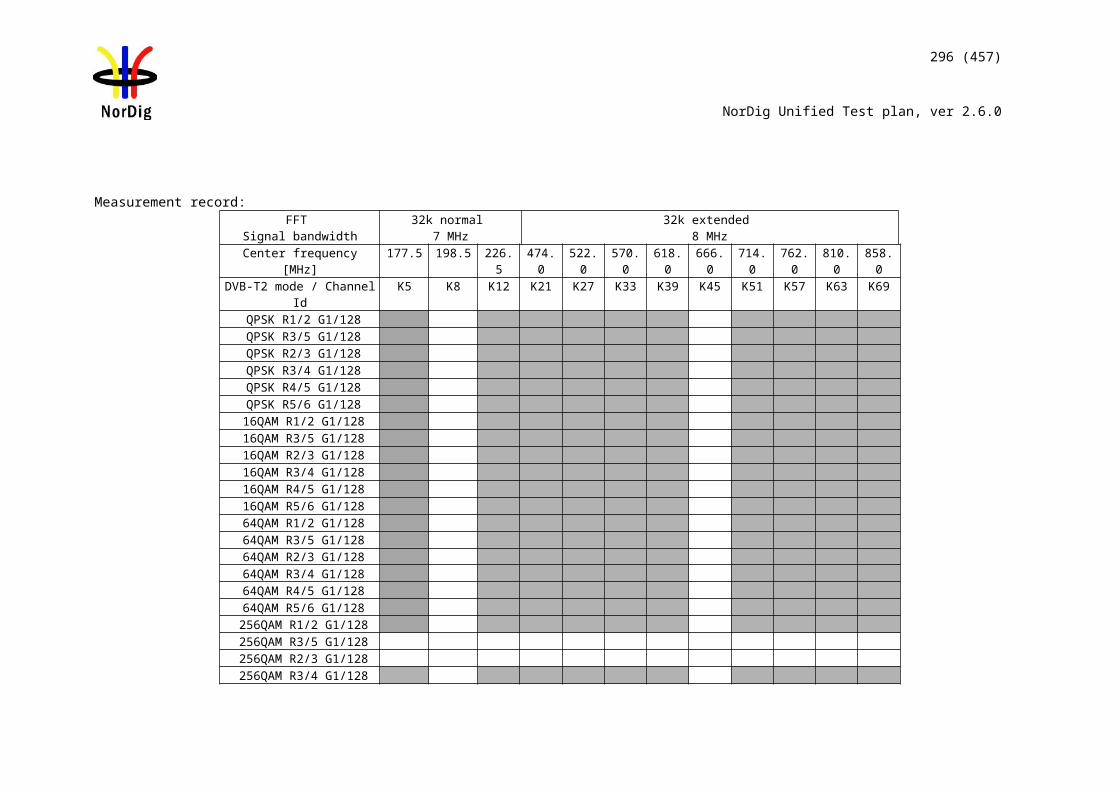
296 (457)
NorDig Unified Test plan, ver 2.6.0
Transmitter Service 1 Service 2 FrequencyMUX 1TS_ID 1Network_ID 1ON_ID 1)
SID 1100S_Name Test11PMT PID 1100V PID 1109A PID 1108ISO639_language_code 2) Audio_type 0x00A PID 1107 ISO639_descriptor:language_code 2) audio_ type 0x00 supplementary audio desc:“broadcast mixed”LCD 1 visible
SID 1200S_Name Test12PMT PID 1200V PID 1209A PID 1208ISO639_language_code 2) Audio_type 0x00A PID 1207 ISO639_descriptor:language_code 2) Audio_type 0x03supplementary audio desc“receiver mixed)LCD 2 visible
Can be chosendepending of thedistribution media.
1) ON_id (Original_network_id) can be chosen in range 0x0001-0xfe00 (operational network)2) Language must the same for all audio components and it can be one of the swe/fin/nor/ice/dan/smi/gle/iri/eng/und
Test procedure:
The selected language for primary language code is referred as Lang1 below.The selected language for secondary language code is referred as Lang2 below.
1. Set the primary audio selection to Lang1 and secondary to Lang2.2. Set audio type preference to “normal” audio.3. Tune to Service 1 and verify that audio PID 1108, Lang1 0x00 audio type is
selected.4. Tune to Service 2 and verify that audio PID 1208, Lang1 0x00 audio type is
selected.5. Set audio type preference to “supplementary audio”.6. Tune to Service 1 and verify that audio PID 1107, Lang2 0x00 audio type is
selected.7. Tune to Service 2 and verify that audio PID 1207, nar 0x03 audio type is mixed
with audio PID 1208 audio and is audible.
Expected result:
Supplementary audio can be enabled and disabled from the menu. IRD supports both broadcast mixed and receiver mixed supplementary audio. IRD is able to select a correct audio track according to user preference setting.
Test result(s)Conformity OK Fault Major Minor, define fail reason in commentsComments If possible describe if fault can be fixed with software update: YES NO
Describe more specific faults and/or other information
Date Sign
Test Case Task 7:32 IRD Internal Reference Level
Section NorDig Unified 6.12
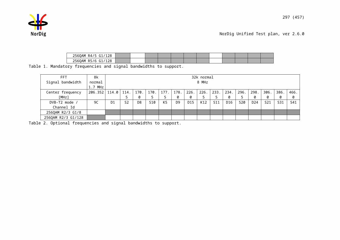
297 (457)
NorDig Unified Test plan, ver 2.6.0
Requirement The level for reference tones for transmission will be 18 dB below clipping level, in accordance with EBU Recommendation R.68 ”Alignment level in digital audio production equipment and in digital recorders” as recommended by ETSI TS 101 154.
IRD Profile(s) Basic, IRD, FETest procedure
The IRD manufacturer shall describe the used test procedure and the used test setup.
Test result(s) The IRD manufacturer shall describe the used test procedure and the used test setup.
Conformity OK Fault Major Minor, define fail reason in commentsComments If possible describe if fault can be fixed with software update: YES NO
Describe more specific faults and/or other information
Date Sign
Test Case Task 7:33 Loudness levels - Audio Output Levels
Section NorDig Unified 6.13.3Requirement In order to match the loudness of PCM and coded audio streams in a downstream AV
receiver, PCM streams at a target reference level of -23 dBFS shall (1) be reduced in level by 8dB before being output on S/PDIF or HDMI to that device. PCM streams at a target reference level of -31 dBFS shall not be increased in level prior to output. When an HDMI Sink device indicates in its E-EDID structure that it supports multichannel audio, then the output should be at a target reference level of -31 dBFS.When an HDMI Sink device indicates in its E-EDID structure that it only supports Basic Audio (i.e. twochannel L-PCM), then the output should be leveled to a target reference level of -23 dBFS.For analog (stereo) outputs, the target reference level should be leveled to -23 dBFS (as measured on a digital signal).
IRD Profile(s) Basic, IRD, FETest procedure Purpose of test:
To verify IRD audio output levels are according to requirement.
Test procedure:
Use a test stream with audio encoded in MPEG-1 Layer II at on a beforhand measured integrated level that is approximately -23 LUFS (integrated value, measured according to EBU R 128 or other close standard such as ITU-R BS.1770).
Available input format
Measured Output on S/PDIF (Integrated value in LUFS)
OK/NOK
When Stereo is selected (default)
– The Target Reference Level is
-23 dBFS
When Multichannel is selected – The Target Reference Level is -31 dBFS
MPEG1 layer II i.e. measured to be -23 LUFS
-23 LUFS (same as input)
-31 LUFS (8 dB attenuation)
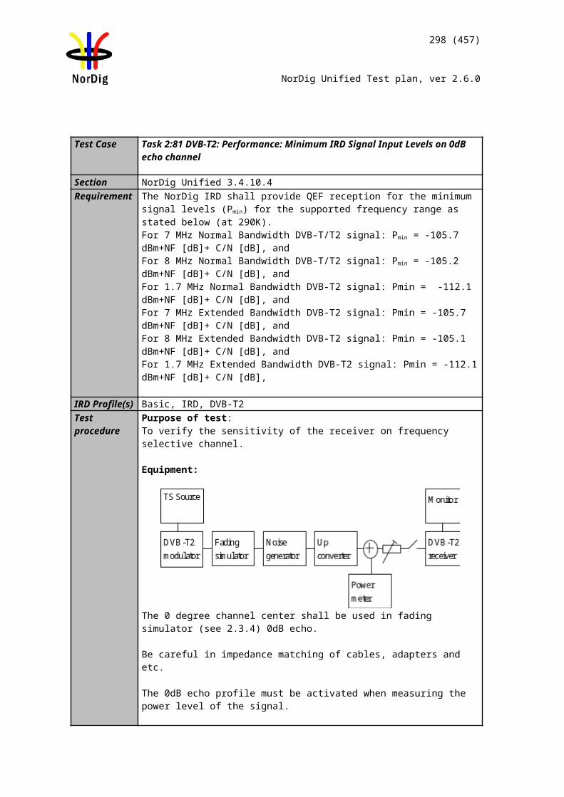
298 (457)
NorDig Unified Test plan, ver 2.6.0
AC-3 i.e. measured to be -23 LUFS with dialnorm level set to = -23 dBFS
-23 LUFS -31 LUFS
E-AC-3 i.e. measured to be -23 LUFS with dialnorm level set to = -23 dBFS
-23 LUFS -31 LUFS
HE AAC i.e. measured to be -23 LUFS with prog_ref_level set to = -23 dBFS
-23 LUFS -31 LUFS
Available input format
Measured Output on HDMI* (Integrated value in LUFS)
OK/NOK
When Stereo is selected (default)
– The Target Reference Level is
-23 dBFS
When Multichannel is selected – The Target Reference Level is -31 dBFS
MPEG1 layer II i.e. measured to be -23 LUFS
-23 LUFS (same as input)
-31 LUFS (8 dB attenuation)
AC-3 i.e. measured to be -23 LUFS with dialnorm level set to = -23 dBFS
-23 LUFS -31 LUFS
E-AC-3 i.e. measured to be -23 LUFS with dialnorm level set to = -23 dBFS
-23 LUFS -31 LUFS
HE AAC i.e. measured to be -23 LUFS with prog_ref_level set to = -23 dBFS
-23 LUFS -31 LUFS
* An audio analyser with HDMI-input is not common. A HDMI-to-S/PDIF-converter might be of use or other type of equipment.
Available input format
Measured Output on S/PDIF (Integrated value in LUFS)
OK/NOK
299 (457)
NorDig Unified Test plan, ver 2.6.0
When Stereo is selected (default)
– The Target Reference Level is
-23 dBFS
When Multichannel is selected – The Target Reference Level is -31 dBFS
MPEG1 layer II i.e. measured to be -23 LUFS
-23 LUFS (same as input)
-31 LUFS (8 dB attenuation)
AC-3 i.e. measured to be -23 LUFS with dialnorm level set to = -23 dBFS
-23 LUFS -31 LUFS
E-AC-3 i.e. measured to be -23 LUFS with dialnorm level set to = -23 dBFS
-23 LUFS -31 LUFS
HE AAC i.e. measured to be -23 LUFS with prog_ref_level set to = -23 dBFS
-23 LUFS -31 LUFS
For analog (stereo) outputs, the target reference level should be leveled to -23 dBFS (as measured on a digital signal).- Make the same tests as “Stereo” as above.
Expected result: IRD supports correct loudness levels. Make sure that the audio level drops when changing from “Stereo” mode to “Multichannel” mode and vice versa.
Test result(s)
Conformity OK Fault Major Minor, define fail reason in commentsComments If possible describe if fault can be fixed with software update: YES NO
Describe more specific faults and/or other information
Date Sign
Test Case Task 7:34 AC-4: Requirements
Section NorDig Unified 6.2.4.1Requirement NorDig HEVC IRD supporting AC-4 shall
• decode AC-4 streams at all bit rates and sample rates listed in ETSI TS 103 190-2 [x].• be capable of transcoding AC-4 bitstreams to E-AC-3 or AC-3 bitstreams according to TS 102 366 [35].
IRD Profile(s) HEVCTest procedure Purpose of test:
To verify that the IRD supports decoding of AC-4 level 3 bitstreams at various audio frame rates.This test is to be performed at the main output of the IRD.
Equipment:
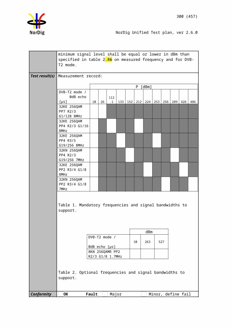
Audio decoder
MUX Exciter IRDTS Source
300 (457)
NorDig Unified Test plan, ver 2.6.0
The TS shall contain a service with an AC-4 audio stream containing multiple presentations in different languages:
an AC-4 stereo presentation in English with relevant signaling at native frame rate.
an AC-4 multichannel presentation in Swedish with relevant signaling at a frame rate of 50 fps.
an AC-4 immersive presentation in Icelandic with relevant signaling at a frame rate of 50 fps.
Test procedure:
14. If the main output of the IRD is HDMI, connect the IRD to an audio receiver, e.g. Home Theater System with HDMI.
15. Verify that service has a multiple AC-4 audio presentations available.16. In receiver menu, choose English as preferred language.17. Verify that AC-4 stereo is decoded or transcoded at the main output of the IRD.18. In receiver menu, choose Swedish as preferred language.19. Verify that AC-4 multichannel is decoded or transcoded.20. In receiver menu, choose Icelandic as preferred language.21. Verify that AC-4 immersive is decoded or transcoded.
Expected result:
IRD support for AC-4 input audio signal and reproduction at its main output.
Test result(s)Frame rate NOK or OK
StereoMultichannel 5.1Immersive
Conformity OK Fault Major Minor, define fail reason in commentsComments If possible describe if fault can be fixed with software update: YES NO
Describe more specific faults and/or other information
Date Sign
Test Case Task 7:35 AC-4: Analogue audio output
Section NorDig Unified 6.2.4.1Requirement The NorDig IRD with SCART and/or analogue outputs shall always have an audio
signal present on the analogue outputs (SCART and stereo out, see section 8.5 and to built-in loudspeakers (see note 1)) if any of the supported formats is received.
Source MUX Exciter DVB receiver
Monitor
301 (457)
NorDig Unified Test plan, ver 2.6.0
If the NorDig IRD has analogue stereo output(s), it shall be capable of decoding and downmixing the supported audio formats for the analogue outputs.
NorDig HEVC IRD supporting AC-4 shall• (additionally) decode AC-4 streams at all bit rates and sample rates listed in ETSI TS 103 190-2 [x].
IRD Profile(s) HEVCTest procedure Purpose of test:
To verify that receiver decodes AC-4 bitstream and audio output level can be adjusted.
This test in only mandatory for STB or IDTV with SCART or analogue audio output interface.
Equipment:
A transport stream containing a service with AC-4 multichannel audio.
Test procedure:
6. Verify that service has a multichannel AC-4 audio available.7. Verify that AC-4 multichannel is downmixed to stereo at analog audio output.
Expected result:
IRD supports AC-4 audio decoding and audio is downmixed to stereo in analog audio output(s).
The audio output level can be adjusted.
Test result(s)Conformity OK Fault Major Minor, define fail reason in commentsComments If possible describe if fault can be fixed with software update: YES NO
Describe more specific faults and/or other information
Date Sign
Test Case Task 7:36 AC-4: HDMI output and HDMI ARC interface
Section NorDig Unified 6.2.4.3Requirement NorDig HEVC IRDs shall be capable of providing the following formats on the HDMI
output connector from an AC-4 bitstream (see chapter 16 for factory default settings):
• AC-4 bitstream decoded (up to 5.1 channels) and re-encoded to E-AC-3 at a minimum bit rate of 640 kbps.• AC-4 bitstream decoded (up to 5.1 channels) and re-encoded to AC-3 at a fixed bit rate
MPEG-2 source
MUX Exciter DVB receiver
HDMI receiver
Monitor
302 (457)
NorDig Unified Test plan, ver 2.6.0
of 640 kbps.• Decoded and downmixed (if > 2 channels) to PCM stereo bitstream
IRD Profile(s) HEVCTest procedure Purpose of test:
To verify that receiver decodes/transcodes an AC-4 bitstream.To verify for the decoded AC-4 bitstream that the audio output level can be adjusted.
This test in only relevant for IRD with HDMI output.
Equipment:
A transport stream with AC-4 multichannel audio.
Test procedure:
8. Connect the IRD to an HDMI receiver e.g. Home Theater System with HDMI.9. Verify that service has a multichannel AC-4 audio available.10. In receiver menu, select stereo audio.11. Verify that AC-4 multichannel is decoded and downmixed to PCM stereo
bitstream for HDMI output and HDMI ARC.12. Verify the audio output level can be adjusted.13. In receiver menu, select multichannel audio.14. Verify that AC-4 multichannel is transcoded to E-AC-3 or AC-3 multichannel
at HDMI output and HDMI ARC.
Expected result:
IRD supports AC-4 audio decoding and downmixing to PCM stereo when stereo audio is selected. The main audio level can be adjusted.IRD supports AC-4 multichannel audio transcoding to E-AC-3 and AC-3 at its HDMI output and HDMI ARC multichannel audio is selected.
Test result(s)Conformity OK Fault Major Minor, define fail reason in commentsComments If possible describe if fault can be fixed with software update: YES NO
Describe more specific faults and/or other information
Date Sign
Test Case Task 7:37 AC-4: S/PDIF output interface
MPEG-2 source
MUX Exciter DVB receiver
S/PDIF receiver
Monitor
303 (457)
NorDig Unified Test plan, ver 2.6.0
Section NorDig Unified 6.2.4.3Requirement The NorDig IRD supporting AC-4 and including an S/PDIF output shall be capable of
providing the following formats on the S/PDIF connector from an AC-4 bitstream:• AC-4 bitstream transcoded to AC-3 bitstream• Decoded and downmixed (if > 2 channels) to PCM stereo bitstream
IRD Profile(s) HEVCTest procedure Purpose of test:
To verify that receiver decodes/transcodes AC-4 bitstream.
This test is only relevant for IRD with S/PDIF output.
Equipment:
A transport stream with AC-4 multichannel audio.
Test procedure:
7. Connect the IRD to a S/PDIF receiver e.g. Home Theater System with S/PDIF.8. Verify that service has a multichannel AC-4 audio available.9. In receiver menu, select stereo audio.10. Verify that AC-4 multichannel is decoded and downmixed to PCM stereo
bitstream for S/PDIF output.11. In receiver menu, select multichannel audio.12. Verify that AC-4 multichannel is transcoded to AC-3 at the S/PDIF output.
Expected result:
IRD supports AC-4 audio decoding to PCM stereo bitstream when stereo audio is selected. IRD supports AC-4 transcode to AC-3 when multichannel audio is selected.
Test result(s)Conformity OK Fault Major Minor, define fail reason in commentsComments If possible describe if fault can be fixed with software update: YES NO
Describe more specific faults and/or other information
Date Sign
Test Case Task 7:38 Dialogue Enhancement
Section NorDig Unified 6.10Requirement Next Generation Audio enable Dialogue Enhancement accessibility services by offering
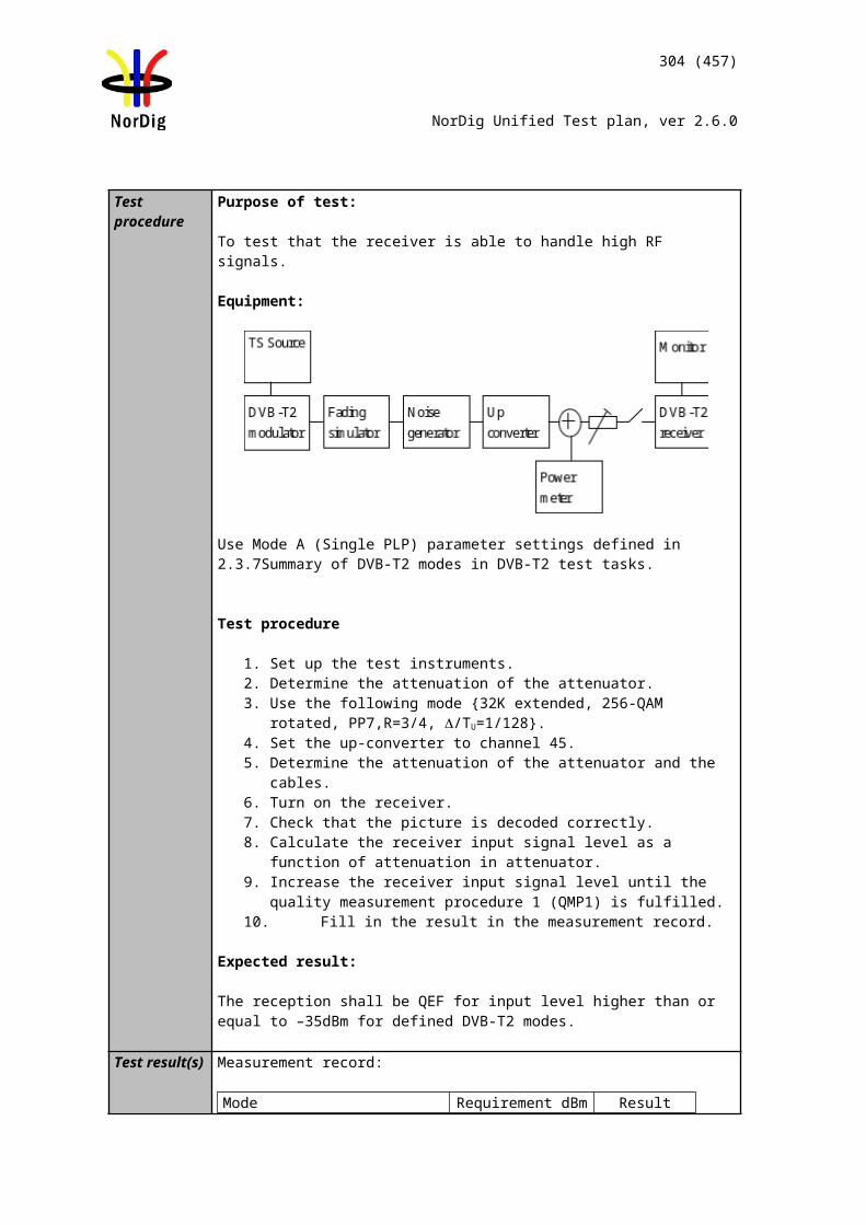
Audio decoder
MUX Exciter IRDTS Source
304 (457)
NorDig Unified Test plan, ver 2.6.0
the possibility to adjust the relative level of the dialogue.
In additions for NGA capable NorDig HEVC IRD user shall be able to select storable user preferences (stored as persistent settings) for following audio related functions (see chapter 16.4 for factory default values):• Dialogue Enhancement (on/off), see section 6.10
IRD Profile(s) HEVCTest procedure Purpose of test:
To verify that the IRD supports Dialogue Enhancement
Equipment:
The TS shall contain a service using AC-4 which include Dialogue Enhancement meta data
Test procedure:
1. Verify that service has an AC-4 audio available including dialogue enhancement meta data.
2. In receiver menu, select Dialogue Enhancement on.3. Verify that AC-4 is decoded and dialogue level is boosted.
Test result(s)Conformity OK Fault Major Minor, define fail reason in commentsComments If possible describe if fault can be fixed with software update: YES NO
Describe more specific faults and/or other information
Date Sign
Test Case Task 7:39 Audio prioritisation for NGA capable NorDig HEVC IRDs
Section NorDig Unified 6.5.2Requirement
NGA capable NorDig HEVC IRD shall prioritise the selection of NGA/AC-4 audio PID/stream over other audio PIDs/streams using other audio codecs when:
NGA stream signalised a language that matches IRD user preference settings for primary audio language. (See section 6.5.4.1 how IRD shall detect language for PMT signalling), or
NGA stream does not signalise any language (in PMT), or NGA stream(s) and all other non-NGA stream(s) languages do not
match IRD user preference settings for audio language.
Otherwise, the non-NGA audio PIDs/streams shall be selected in accordance with section 6.5.3 below. For the case that the NGA capable NorDig HEVC IRD finds more than one NGA stream that matches the primary audio language, the stream with lowest PID shall be selected.
Audio decoder
MUX Exciter IRDTS Source
305 (457)
NorDig Unified Test plan, ver 2.6.0
IRD Profile(s) HEVCTest procedure Purpose of test:
To verify that the IRD selects the right PID/stream based on IRD primary language setting.
Equipment:
A transport stream containing a service with multiple audio PID in different languages and audio codecs.
PID Codec Language signaling
Content
1st audio PID HE-AAC Swedish Sine tone2nd audio PID Dolby AC-4 Finnish and
SwedishFinnish: musicSwedish: speech*
3rd audio PID HE-AAC English English: speech** Speech content is a narration in English indicating the selected language
Test procedure:1. Setup the system as indicated in the diagram2. In the IRD user preference settings, set the primary audio language to Swedish3. Verify the IRD selects the 2nd audio PID and plays back the speech content
corresponding to Swedish language and not the sine tone.
4. In the IRD user preference settings, set the primary audio language to English5. Verify the IRD selects the 3rd audio PID and plays back the speech content
corresponding to English language.
6. In the IRD user preference settings, set the primary and secondary audio language to any languages other than Swedish, Finnish or English.
7. Verify the IRD selects the 2nd audio PID and plays back the music content corresponding to Finnish language.
Expected result:There are three verification steps in this test procedure:
In step 3, the IRD prioritises the NGA PID because it matches the user preference for primary audio language.In step 5, the IRD prioritises the non-NGA PID because the NGA PIDs don’t match the user preference for primary audio language and the NGA PID does.In step 7, the IRD prioritises the NGA PID because neither the NGA nor the non-NGA PIDs match the user preference for primary audio language.
Test result(s) Primary/secondary language preference
Decoded audio stream content
OK/NOK
Swedish Speech corresponding to Swedish language
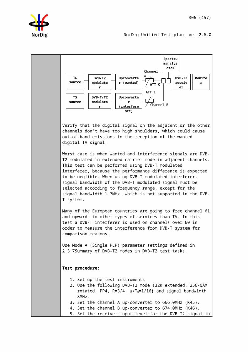
Audio decoder
MUX Exciter IRDTS Source
306 (457)
NorDig Unified Test plan, ver 2.6.0
English Speech corresponding to English language
Any languages other than Swedish, Finnish or English
Music corresponding to Finnish language
Conformity OK Fault Major Minor, define fail reason in commentsComments If possible describe if fault can be fixed with software update: YES NO
Describe more specific faults and/or other information
Date Sign
Test Case Task 7:40 Audio prioritisation for NGA capable NorDig HEVC IRDs
Section NorDig Unified 6.5.2Requirement
NGA capable NorDig HEVC IRD shall prioritise the selection of NGA/AC-4 audio PID/stream over other audio PIDs/streams using other audio codecs when:
NGA stream signalised a language that matches IRD user preference settings for primary audio language. (See section 6.5.4.1 how IRD shall detect language for PMT signalling), or
NGA stream does not signalise any language (in PMT), or NGA stream(s) and all other non-NGA stream(s) languages do not
match IRD user preference settings for audio language.
Otherwise, the non-NGA audio PIDs/streams shall be selected in accordance with section 6.5.3 below. For the case that the NGA capable NorDig HEVC IRD finds more than one NGA stream that matches the primary audio language, the stream with lowest PID shall be selected.
IRD Profile(s) HEVCTest procedure Purpose of test:
To verify that the IRD selects the right PID/stream when the NGA stream does not signal any language in PMT
Equipment:
A transport stream containing a service with multiple audio PID in different languages and audio codecs.
PID Codec Language signaling
Content
1st audio PID HE-AAC Swedish Sine tone2nd audio PID Dolby AC-4 Finnish and
SwedishNo signaling in the PMT
Finnish: musicSwedish: speech*
* Speech content is a narration in English indicating the selected language
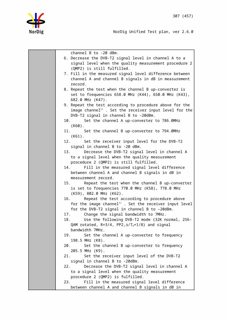
307 (457)
NorDig Unified Test plan, ver 2.6.0
Test procedure:1. Setup the system as indicated in the diagram2. In the IRD user preference settings, set the primary audio language to Swedish3. Verify the IRD selects the 2nd audio PID and plays back the speech content
corresponding to Swedish language and not the sine tone.
Expected result:The IRD prioritises the NGA stream when it does not signal any language in the PMT
Test result(s) Primary/secondary language preference
Decoded audio stream content
OK/NOK
Swedish Speech corresponding to Swedish language
Conformity OK Fault Major Minor, define fail reason in commentsComments If possible describe if fault can be fixed with software update: YES NO
Describe more specific faults and/or other information
Date Sign
Test Case Task 7:41 Audio Prioritisation inside the NGA Audio PID/stream
Section NorDig Unified 6.5.6Requirement
This section applies only to the NGA capable NorDig HEVC IRD.
The NGA capable NorDig IRD shall prioritise the preselection in the NGA stream according to Table 6.4.
IRD settings →
Audio Description OFF Audio Description ON
Spoken Subtitles OFF
Spoken Subtitles ON
Spoken Subtitles OFF
Spoken Subtitles ON
IRD behaviour depending on above IRD settings and preselection properties
Priority Priority with respect to best matching preselection
Priority with respect to best matching preselection
1 AD off and SS off Preselection matching primary audio language
AD off and SS on Preselection matching primary audio language
AD on and SS off Preselection matching primary audio language (1)
AD on and SS on Preselection matching primary audio language
2 AD off Preselection matching primary audio language
SS on Preselection matching primary audio language
AD on and SS on Preselection matching primary audio language
AD on and SS off Preselection matching primary audio language
3 Preselection matching primary audio language
Preselection matching primary audio language
SS off Preselection matching primary audio language
SS on Preselection matching primary audio language
4 AD off and SS off Preselection matching secondary audio language
AD off and SS on Preselection matching secondary audio language
Preselection matching primary audio language
Preselection matching primary audio language
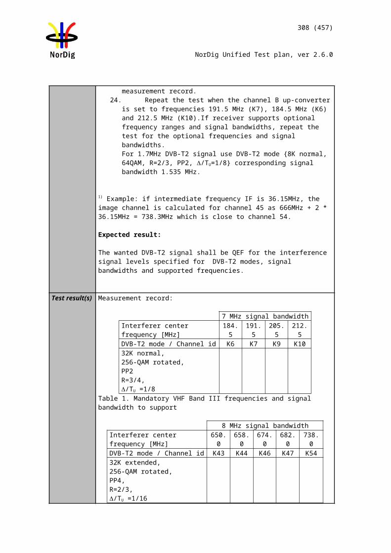
Audio decoder
MUX Exciter IRDTS Source
308 (457)
NorDig Unified Test plan, ver 2.6.0
5 AD off Preselection matching secondary audio language
SS on Preselection matching secondary audio language
AD on and SS off Preselection matching secondary audio language settings
AD on and SS on Preselection matching secondary audio language
6 Preselection matching secondary audio language
Preselection matching secondary audio language
AD on and SS on Preselection matching secondary audio language
AD on and SS off Preselection matching secondary audio language
7 (if no match) default Preselection
(if no match) default Preselection
SS off Preselection matching secondary audio language
SS on Preselection matching secondary audio language
8 Preselection matching secondary audio language
Preselection matching secondary audio language
9 (if no match) default Preselection
(if no match) default Preselection
Table 6.4 Audio Priority between NGA Preselections for NGA “Accesibility Services” with Audio description on/off and Spoken Subtitles on/off. A lower number refers to higher priority.
Note 1: This selection requires the IRD to evaluate the audio preselection descriptor.
IRD Profile(s) HEVCTest procedure Purpose of test:
To verify that the IRD selects the right PID/stream based on IRD primary language setting.
Equipment:
A transport stream containing a service with a single audio NGA PID with multiple preselections in different languages with the following content:
1. Finnish preselection with a music as content2. Swedish preselection with speech* as content3. English preselection with speech* as content4. Finnish preselection including Audio Description with a mix of music and
speech* Speech content is a narration in English indicating the selected language
Test procedure:1. Setup the system as indicated in the diagram2. In the IRD user preference settings, set the primary audio language to Swedish3. Verify the IRD selects the second preselection and plays back the speech
content corresponding to Swedish language.4. In the IRD user preference settings, set the primary audio language to Icelandic
and the secondary audio language to English5. Verify the IRD selects the third preselection and plays back the speech content
corresponding to English language.
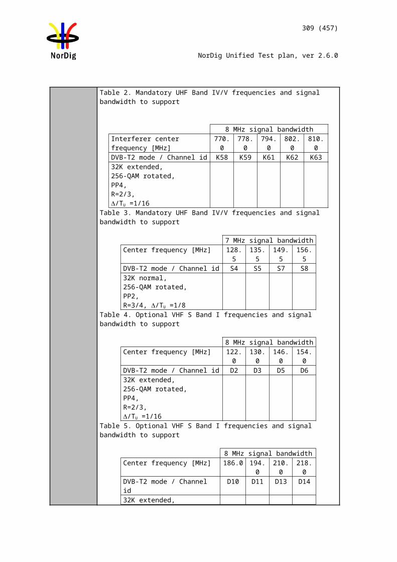
309 (457)
NorDig Unified Test plan, ver 2.6.0
6. In the IRD user preference settings, set the primary audio language to Finnish and enable accessibility settings for Audio Description.
7. Verify the IRD selects the fourth preselection and plays back the mix of music and speech corresponding to Finnish language
Expected result:There are three verification steps in this procedure:
In step 3, the IRD prioritises the Swedish preselection because it matches the user preference for primary audio language.In step 5, the IRD prioritises the English preselection because it maches the user preference for secondary audio language and no other preselection matches the primary audio language.In step 7, the IRD prioritises the Finnish preselection with Audio Description because it maches the user preference for primary audio language and accesibility settings.
Test result(s) Primary/secondary language preference
Accessibility settings
Decoded audio stream content
OK/NOK
Primary: Swedish AD offSS off
Speech corresponding to Swedish language
Primary: IcelandicSecondary: English
AD offSS off
Speech corresponding to English language
Primary: Finnish AD onSS off
Mix of music and speech corresponding to Finnish language
Conformity OK Fault Major Minor, define fail reason in commentsComments If possible describe if fault can be fixed with software update: YES NO
Describe more specific faults and/or other information
Date Sign
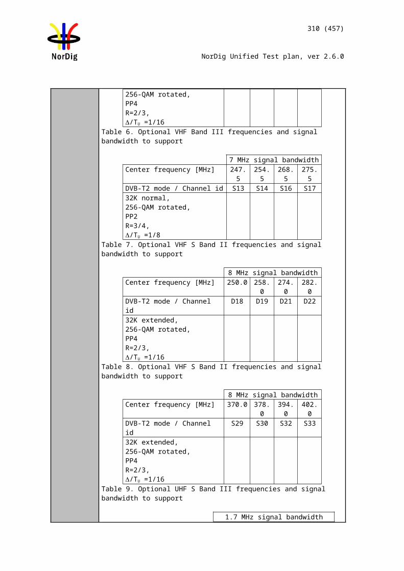
310 (457)
NorDig Unified Test plan, ver 2.6.0
2.8 Task 8: Teletext and subtitling
Test Case Task 8:1 Subtitling - user preferences
Section NorDig Unified 7.1Requirement The IRD shall have user selection of subtitling preferences for ‘normal’ or ‘hard of
hearing’ subtitles. The user preference settings for subtitling should be common for EBU Teletext subtitling and DVB Subtitling,see section 16 for factory default settings of the subtitling.
Note: Correct functionality for the Hard of Hearing/hearing impaired service, requires that the Content Providers delivers this service as a mix of translated subtitling and Hard of Hearing/hearing impaired subtitling.
IRD Profile(s) Basic, IRD, FETest procedure
This is a general requirement which will be verified in the following test tasks
Test Case Task 8:2 Subtitling - Only display subtitling if match language in user preferences
Section NorDig Unified 7.1.2Requirement The NorDig IRD shall only display subtitles, if a language of the received subtitle
matches any of the NorDig IRD’s user preference settings for language for subtitling. (This means that if none of languages for the received subtitle(s) match any of the IRD’s user preference settings language for subtitling, then the NorDig IRD shall not display any subtitles).
IRD Profile(s) Basic, IRD, FE
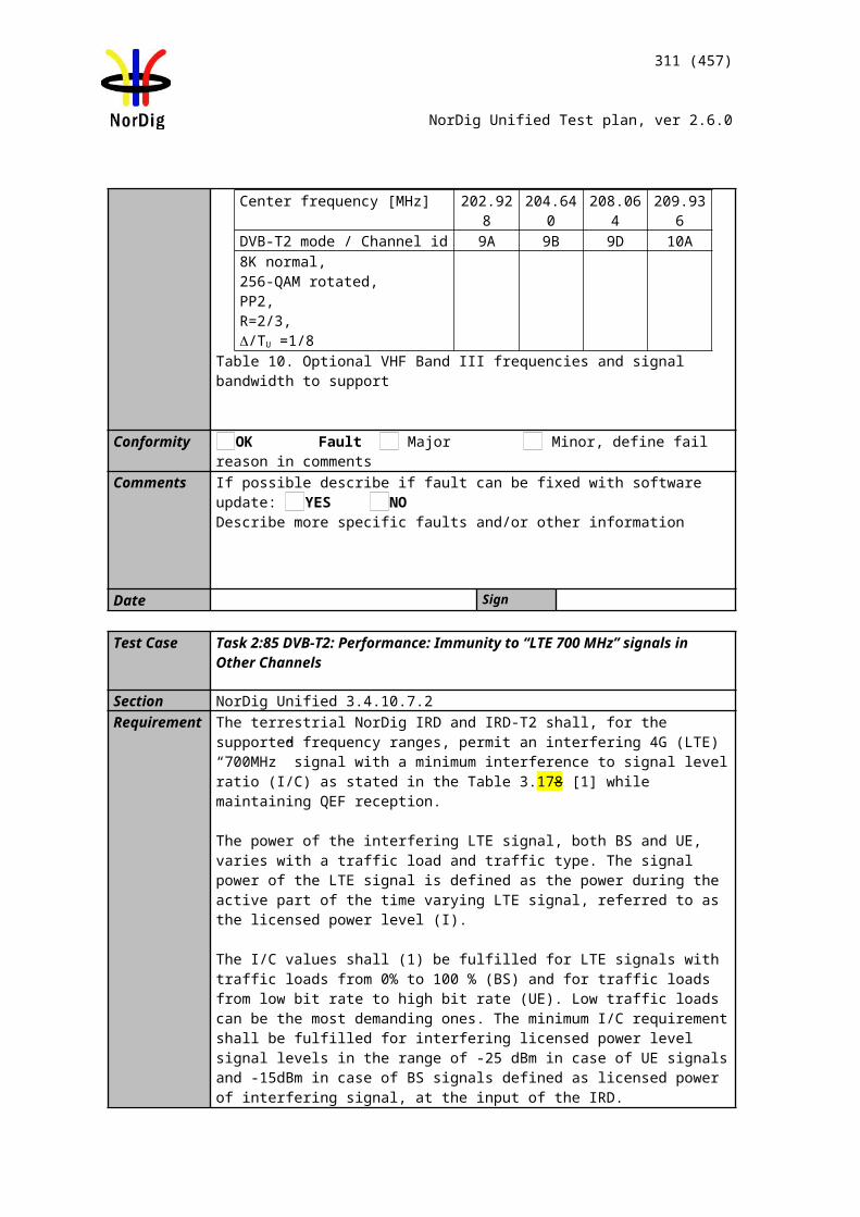
311 (457)
NorDig Unified Test plan, ver 2.6.0
Test procedure Purpose of test:To verify that the IRD only display subtitles, if a language of the received subtitle matches any of the IRD’s user preference settings for language for subtitling.
Equipment:
Test signal configuration:A transport stream is used as a test signal. Within transport stream at least two services are carried with subtitling components.One of the services shall match with the subtitling language settings in IRD and the other service is not matching to any language settings.
Test procedure:1. Tune IRD to a service that includes subtitling service that matches the IRD
language settings.2. Verify that the correct subtitling is selected 3. Tune IRD to a service that includes subtitling service that DO NOT match the
IRD language settings.4. Verify that the NO subtitling is selected
Expected results:The IRD do not display any subtiling if the user preference’s subtitling languge do not match with the broadcasted subtitling languages.
Test result(s)Conformity OK Fault Major Minor, define fail reason in commentsComments If possible describe if fault can be fixed with software update: YES NO
Describe more specific faults and/or other information
Date Sign
Test Case Task 8:3 Subtitling - Temporary changes to subtitling settings
Section NorDig Unified 7.1.3Requirement In case of the user has made temporary changes of the subtitling settings (i.e. without
changing the IRD’s user preference setting), then this change shall (at least) remain until the user change service.(Clarification, this means the IRD shall not change back temporary subtitling setting based on EIT events for the service).
IRD Profile(s) Basic, IRD, FE
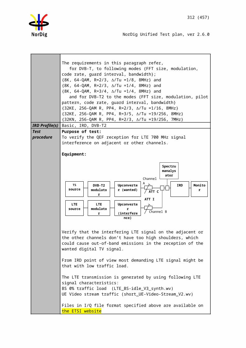
312 (457)
NorDig Unified Test plan, ver 2.6.0
Test procedure Purpose of test:To verify that the IRD supports temporary chaging of the subtitling settings.
Equipment:
Test signal configuration:A transport stream is used as a test signal. Within transport stream at least two services are carried with several subtitling components in several languages.At least in one of the services shall match with the subtitling language settings in IRD and the other service is not matching to any language settings.
Test procedure:1. Tune IRD to a service that includes subtitling service that matches the IRD
language settings.2. Verify that the correct subtitling is selected 3. Change the temporary subtitling setting to anoter language4. Verify that subtitling language is selected according the temporary settings. 5. Tune IRD to a service that includes subtitling service that DO NOT match the
IRD language settings.6. Verify that the NO subtitling is selected7. Tune IRD to a service that includes subtitling service that matches the IRD
language settings.8. Verify that the correct subtitling is selected
Expected results:The IRD supports temporary subtitling language settings.
Test result(s)Conformity OK Fault Major Minor, define fail reason in commentsComments If possible describe if fault can be fixed with software update: YES NO
Describe more specific faults and/or other information
Date Sign
Test Case Task 8:4 Subtitling – Subtitling mode (Normal and Hard of hearing subtitling)
Section NorDig Unified 7.1.4 Requirement In case of ‘normal’ subtitling mode is selected, then the NorDig IRD shall (1) only dis-
play ‘normal’ subtitles (signalised in subtitling descriptor and/or teletext descriptor). In this ‘normal’ subtitling mode the NorDig IRD shall not display any (hard or hearing) subtitling if the subtitling stream only includes ‘hard of hearing’/‘hearing impaired’ pages.
In case of ‘hard of hearing’ subtitling mode is selected and if no ‘hard of hearing’/‘hear-ing impaired’ pages are received (signalised in subtitling descriptor and/or teletext descriptor), then the NorDig IRD shall as a default use ‘normal’ subtitling pages from the same selected language.
313 (457)
NorDig Unified Test plan, ver 2.6.0
IRD Profile(s) Basic, IRD, FETest procedure Purpose of test:
To verify that the IRD can handle signalisation and decoding of “hard of hearing” subtitling when they are broadcasted.or not. To check that composition pages “normal” are chosen by default instead of “hard of hearing”.
Support for ancillary pages is not tested.
Equipment:
A transport stream containing a test services with DVB and EBU Teletext composition subtitling and “hard of hearing” components.
Subtitling composition pages can be divided into two contents: “normal” or “hard of hearing”. Composition pages shall be enabled in mode “normal” by default. Subtitling ancillary pages can be broadcasted for more or less like a “raw data”. Ancillary pages shall be enabled by default.
Test procedure:1. Verify the “hard of hearing” subtitles are enabled2. Start to broadcast the “hard of hearing” subtitles according to correst PSI/SI
signalization.3. Verify receiver is able to handle and decode the “hard of hearing” composition
pages.4. Stop the “hard of hearing” subtitling pages broadcasting. 5. Start the “normal” subtitling pages broadcast. 6. Verify that the receiver automatically starts to decode “normal” subtitling
pages.
Expected result: Hard of hearing content of the DVB and EBU Teletext subtitling is handled, displayed and decoded correctly.
The automatic change from “normal” to “hard of hearing” subtitling pages and vice versa is not requirement in NorDig Unified. However, for convenient use of the subtitling composition pages content, a receiver manufacture may choose to have this support due to that all program content is not “hard of hearing” subtitled.
Test result(s)Conformity OK Fault Major Minor, define fail reason in commentsComments If possible describe if fault can be fixed with software update: YES NO
Describe more specific faults and/or other information
Date Sign
Test Case Task 8:5 Subtitling – DVB Subtitling and subtitling priority (DVB/EBU)
Section NorDig Unified 7.1.5 and 7.3Requirement The NorDig IRD shall be capable of decoding, as a minimum, a subset of the DVB
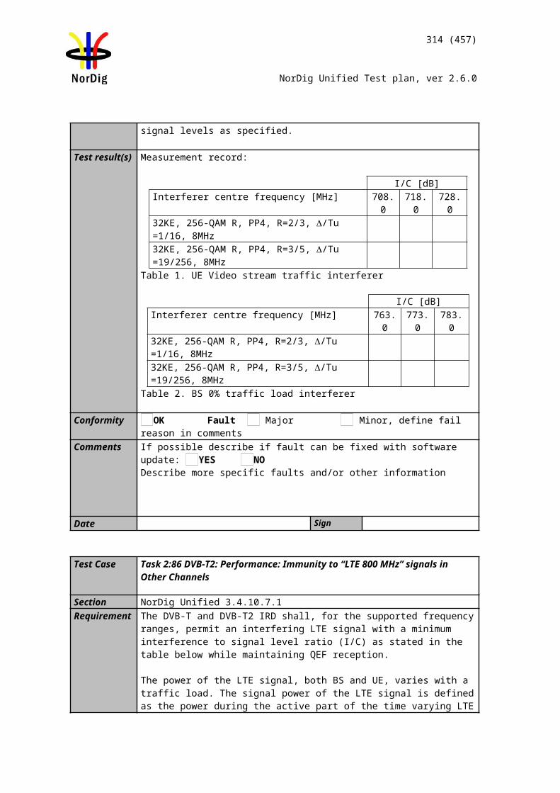
314 (457)
NorDig Unified Test plan, ver 2.6.0
subtitle services asspecified in section 7.3.2 and transmitted in conformance with ETS 300 743 [20], and displayed using theOSD capabilities whilst decoding the full television service (video and audio) to which it is associated.
The NorDig IRD shall be able to display both ‘normal’ and ‘hard of hearing’ subtitles, according to userpreference settings.
Within DVB Subtitling it is possible to transmit common pages for all languages and subtitling streamsinside one DVB subtitling PID, this is referred to as ‘ancillary pages’. Support for ancillary pages isoptional for NorDig IRD. The enabling or disabling of the subtitle ancillary pages, if available, should beuser controlled, with subtitle ancillary pages enabled as default option. The selection of subtitle ancillarypages shall be independent of the enabling of subtitle composition pages.
The precision of the presentation of the subtitles shall be within 2 frames.IRD Profile(s) Basic, IRD, FETest procedure Purpose of test:
To verify that DVB subtitling is implemented, and that it has higher priority than Teletext subtitling.
Equipment:
A transport stream containing a test service with teletext subtitling and DVB subtitling components.
Test procedure:
1. Drop the DVB subtitling component in the mux. Only Teletext subtitling is broadcasted.
2. Zap from, then to, the test service to make sure that the IRD has updated the PMT.
3. Verify that the Teletext subtitling is displayed. Fill in the test protocol.4. Add the DVB Subtitling component in the mux. Both DVB and Teletext is
now present.5. Verify that the DVB subtitling is the only component that the IRD displays.
Fill in the test protocol.6. Verify that the DVB subtitling is in synchronisation with the video for both SD
and HD services for a longer period of time, eg. 45 minutes.. Fill in the test protocol.
7. Enter the language set up and select a subtitling language that is not available as primary subtitling language, but as secondary subtitling language.
8. Verify that the secondary DVB language is displayed, and in sync with the video.
9. Access the menu system for subtitling preferences. 10. Verify the “normal” DVB subtitling can be enabled and disabled. Verify the
functionality. (In case of teletext subtitles are still broadcasted, the decoding of the teletext subtitles should start)
Expected result: All test results are OK.
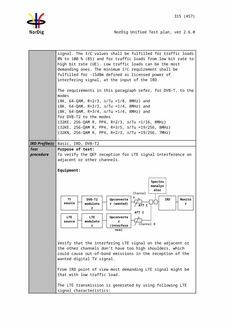
315 (457)
NorDig Unified Test plan, ver 2.6.0
Test result(s) Test protocol
Test point 3
Test point 6-7
Test point 9
Conformity OK Fault Major Minor, define fail reason in commentsComments If possible describe if fault can be fixed with software update: YES NO
Describe more specific faults and/or other information
Date Sign
Test Case Task 8:6 Teletext - Simultaneous EBU Teletext and HbbTV Digital Teletext
Section NorDig Unified 7.1.6 Requirement For services that have both an EBU Teletext service and an HbbTV Digital Teletext ap-
plication signalled and available, the NorDig Hybrid shall (1) be able to start and dis-play the HbbTV Digital Teletext application as well as being able to start and display the EBU Teletext service (one at a time).
The NorDig Hybrid shall (1) start teletext and be able to toggle between any HbbTV Di-gital Teletext and any EBU Teletext service as described in clause 5.3.4 of HbbTV spe-cification ETSI TS 102 796
IRD Profile(s) Basic, IRD, FETest procedure Purpose of test:
To verify that the IRD is able to start EBU Teletext and HbbTV Digital Teletext (one at the time).
Equipment:
316 (457)
NorDig Unified Test plan, ver 2.6.0
A transport stream containing a test services with EBU Teletext and HbbTV Digital Telext application.
Test procedure:1. Tune to a serve that contains both EBU Teletext and HbbTV Digital Teletext
application.2. Verify that the user can toggle between EBU Teletext and HbbTV Digital
Teletext application by pressing the “text” button in the RCU.
Expected result: User can toggle between EBU Teletext and HbbTV Digital Teletext application.
Test result(s)Conformity OK Fault Major Minor, define fail reason in commentsComments If possible describe if fault can be fixed with software update: YES NO
Describe more specific faults and/or other information
Date Sign
Test Case Task 8:7 Subtitling - coexistent with HbbTV applications
Section NorDig Unified 7.1.7Requirement A NorDig Hybrid shall support simultaneous display of HbbTV application and
subtitles (DVB subtitling and EBU teletext subtitling), both for broadcast and at least for MPEG2 TS delivered via broadband [29].
The NorDig Hybrid shall display the HbbTV application over the subtitles as described in clause 10.1.1 of HbbTV specification ETSI TS 102 796 [30]. This means that if the video is up or down-converted, to other than full screen video, the subtitles shall either be rescaled/repositioned appropriately or not displayed at all.
IRD Profile(s) Hybrid, IRD, FETest procedure Purpose of test:
To verify that DVB and EBU teletext subtitling can coexists with HbbTV applications.
Equipment:
A transport stream containing a test service with DVB and EBU teletext composition subtitling component and at least one signaled service bound HbbTV application at the same channel.
Test procedure:1. set the IRD to the autostart mode for the HbbTV services and eansure that
subtitles are enabled2. search channels
317 (457)
NorDig Unified Test plan, ver 2.6.0
3. zap to a channel that contains the HbbTV service and subtitles4. verify that when the HbbTV application is not using the same graphics plane or
area of the plane as the subtitles, the subtitles are visible
Expected result: The subtitles are visible with a HbbTV application, when they are not sharing the same area of the graphics plane.
Test result(s)Conformity OK Fault Major Minor, define fail reason in commentsComments If possible describe if fault can be fixed with software update: YES NO
Describe more specific faults and/or other information
Date Sign
Test Case Task 8:8 Teletext – EBU Teletext level 1.5
Section NorDig Unified 7.2Requirement Level 1.5 teletext and teletext subtitling is displayed.IRD Profile(s) Basic, IRD, FETest procedure Purpose of test:
To check that enhanced teletext (Level 1.5) is decoded and displayed.
Equipment:
Test signal configuration:A transport stream is used as a test signal. Within transport stream at least one service is carried with teletext component. Teletext pages and teletext subtitles shall be ITU-R System B Teletext level 1.5 compatible.
Test procedure:The IRD is tuned to a service that includes ITU-R System B Teletext (Level 1.5).The teletext service is selected.
Test result(s)Conformity OK Fault Major Minor, define fail reason in commentsComments If possible describe if fault can be fixed with software update: YES NO
Describe more specific faults and/or other information
Date Sign
Test Case Task 8:9 Teletext - decoding method(VBI)
Section NorDig Unified 7.2.2
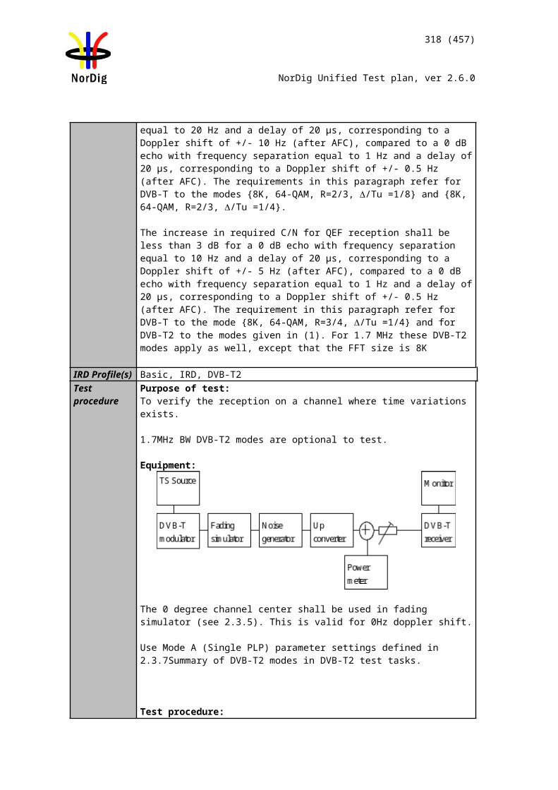
318 (457)
NorDig Unified Test plan, ver 2.6.0
Requirement The NorDig IRD shall for the analogue outputs also support insertion of the teletext data in the VBI of theanalogue CVBS video output. In this case the teletext decoder of the TV-set might be used instead of theone in the STB. The VBI insertion shall be compliant with ITU-R BT.653-3 [64]. The Teletext data shallbe inserted in the lines 6 to 22 and lines 320 to 335..
IRD Profile(s) Basic, IRD, FETest procedure Purpose of test:
To verify that ITU-R System B Teletext data is inserted in the VBI of the analogue CVBS video output and/or it is decoded and displayed in the OSD.
Equipment:
Test procedure:1. The IRD is tuned to a TV service that includes ITU-R System B Teletext.2. Verify that teletext data is inserted onto VBI lines within the range 6-22 and
320-335.
In case of a STB an external TV monitor with embedded teletext decoder is used to decode the Teletext service.In case of an idTV an separate TV monitor with embedded teletext decoder can used to decode the Teletext service from the analog video output.
Expected results:Teletext data is inserted onto VBI lines within the range 6-22 and 320-335.
Test result(s) Test protocol
Requirement NOK or OKVBI of CVBS video insertion supported for teletext pagesVBI of CVBS video insertion supported for teletext subtitles
Conformity OK Fault Major Minor, define fail reason in commentsComments If possible describe if fault can be fixed with software update: YES NO
Describe more specific faults and/or other information
Date Sign
Test Case Task 8:10 Teletext decoding method(OSD)
Section NorDig Unified 7.2.1Requirement During normal operation, the NorDig IRD shall be able to demultiplex in parallel the
Teletext servicetransmitted in a packetised format according EN 300 472 [17].
The NorDig IRD shall include a teletext decoder to be able to display EBU Teletext us-ing the OSD.
IRD Profile(s) Basic, IRD, FETest procedure Purpose of test:
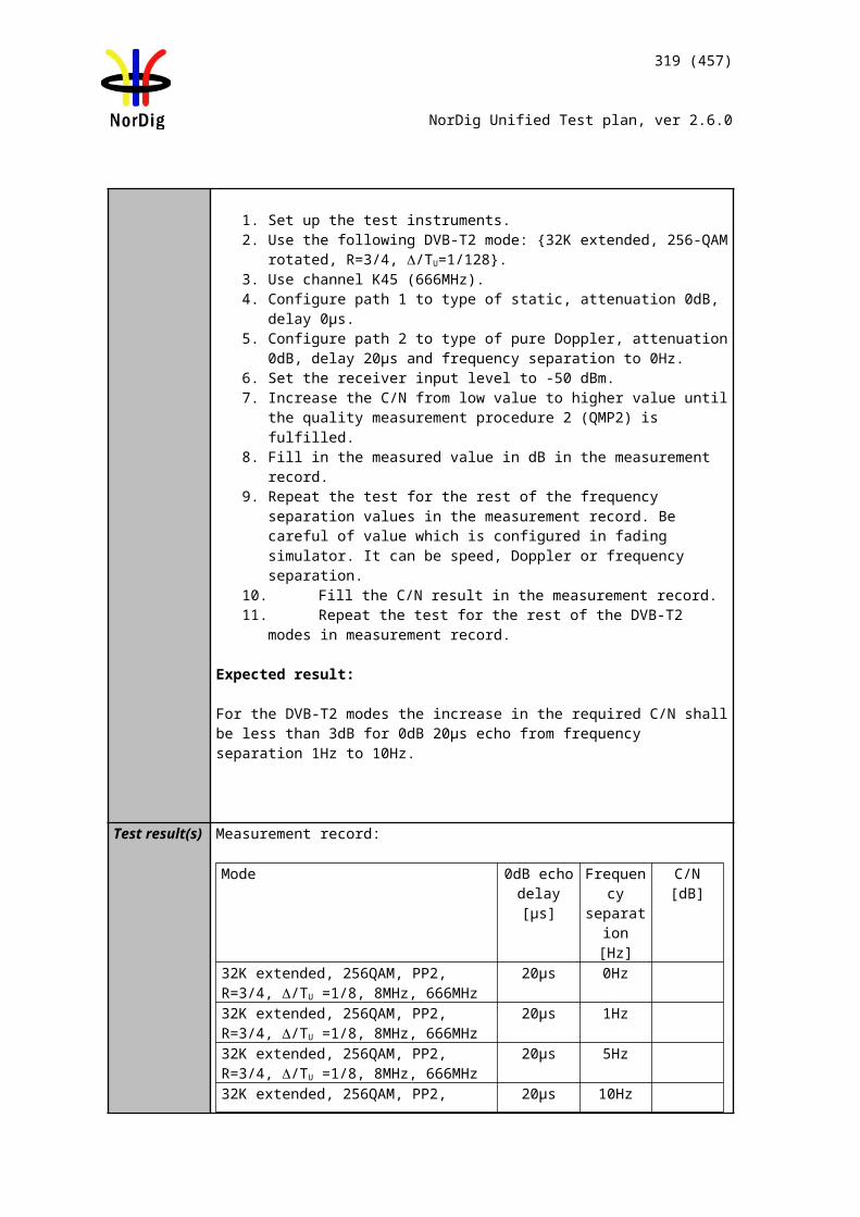
319 (457)
NorDig Unified Test plan, ver 2.6.0
To verify that EN 300 472 [17] data is is decoded and displayed in the OSD.
Equipment:
Test procedure:1. The IRD is tuned to a TV service that includes ITU-R System B Teletext.2. Verify that OSD decoding method is supported, verify the teletext is correctly
decoded on the OSD.
Expected results:Receiver supports the teletext decoding in the OSD.
Test result(s) Test protocol
Requirement NOK or OKOSD decoding supported for teletext pagesOSD decoding supported for teletext subtitles
Conformity OK Fault Major Minor, define fail reason in commentsComments If possible describe if fault can be fixed with software update: YES NO
Describe more specific faults and/or other information
Date Sign
Test Case Task 8:11 Teletext – teletext pages
Section NorDig Unified 7.2.1Requirement
The Nordic characters defined in the Latin G2 supplementary set shall be supported.
IRD Profile(s) Basic, IRD, FETest procedure Purpose of test:
To test the functionality of the teletext decoder concerning teletext pages.
Equipment:
Test procedure:
Start condition: IRD installed on the live network1. Check the teletext function on several services and make sure that it works
properly.
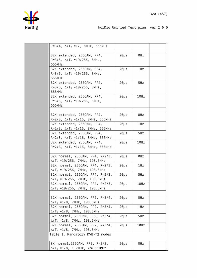
320 (457)
NorDig Unified Test plan, ver 2.6.0
2. Fill in the test protocol.3. Zap to a service with multiple initial pages in different languages. Select an
available language as primary language.4. Verify that the correct initial page is displayed when txt-button is pressed. 5. Fill in the test protocol.6. Repeat 3-4 for another language
Expected result: All test results are OK.
Test result(s) Test protocol:
Test point 1
Test point 2-4
Conformity OK Fault Major Minor, define fail reason in commentsComments If possible describe if fault can be fixed with software update: YES NO
Describe more specific faults and/or other information
Date Sign
Test Case Task 8:12 Teletext – teletext pages - cache
Section NorDig Unified 7.2.1Requirement
The NorDig IRD with OSD presentation shall be able to cache at least 200 decoded Teletext pages in order to improve the access time for frequently used pages.
IRD Profile(s) Basic, IRD, FETest procedure Purpose of test:
To test the functionality of the teletext decoder concerning teletext page cache.
Equipment:
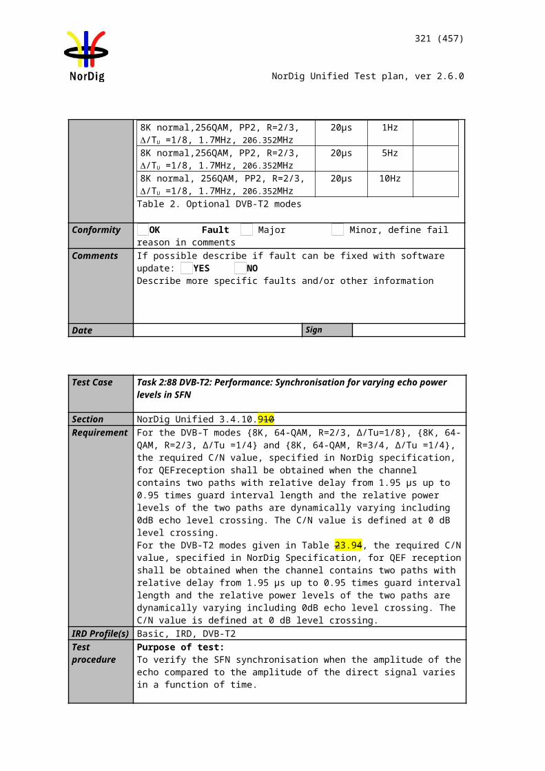
321 (457)
NorDig Unified Test plan, ver 2.6.0
TS contains a service with at least 200 EBU teletext pages.
Test procedure:
1. Check the teletext function on several services and estimate that teletext cache is at least 200 pages.
Expected result: All test results are OK.
Test result(s)Conformity OK Fault Major Minor, define fail reason in commentsComments If possible describe if fault can be fixed with software update: YES NO
Describe more specific faults and/or other information
Date Sign
Test Case Task 8:13 Subtitling – teletext subtitling
Section NorDig Unified 7.1, 7,2Requirement
DVB Subtitling and Teletext Subtitling are mandatory in the NorDig IRDs. The user shall be able toenable and disable displaying of subtitles and to select primary and secondary subtitling language.
The Nordic characters defined in the Latin G2 supplementary set shall be supported.
IRD Profile(s) Basic, IRD, FETest procedure Purpose of test:
To test the functionality of the teletext decoder concerning subtitling.
Equipment:
Test procedure:
Start condition: IRD installed on the network1. Enter the menu and check that it’s possible to select primary and secondary
subtitling language. Fill in the test protocol.
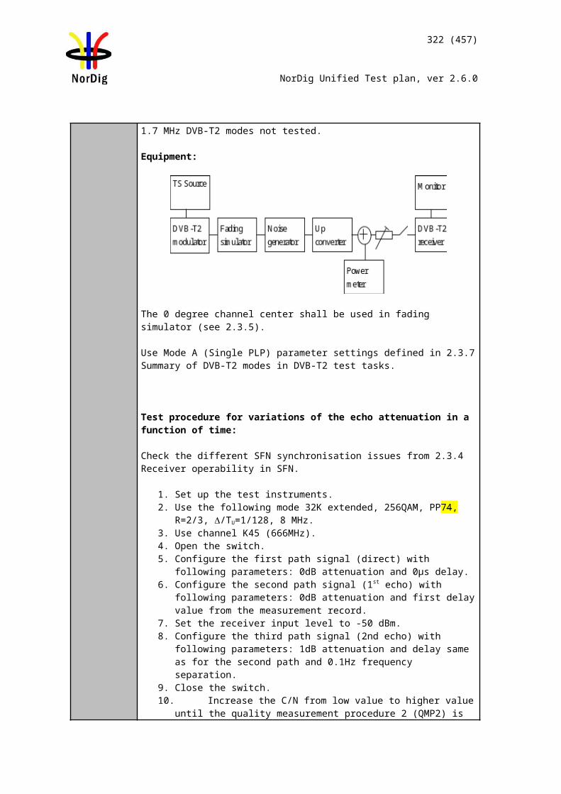
322 (457)
NorDig Unified Test plan, ver 2.6.0
2. Zap to a service with multiple subtitle languages. Select an available language as primary language and check that the subtitling is displayed.
3. Verify that the text is in sync with the video for both SD and HD services for a longer period oftime, eg. 45 minutes.
4. Verify that the nordic characters are displayed correctly.5. Fill in the results in the protocol.6. Enter the language set up and select a language that is not available as primary
language, but as secondary language. 7. Verify that the secondary language text is displayed, and in sync with the
video.8. Verify that the nordic characters are displayed correctly.9. Fill in the results in the protocol.
Repeat 6-9 for the other subtitling languages and fill in the protocol.
Expected result: All test results are OK.
Test result(s) Test protocol:
Test point 1
Test point 2-10
Conformity OK Fault Major Minor, define fail reason in commentsComments If possible describe if fault can be fixed with software update: YES NO
Describe more specific faults and/or other information
Date Sign
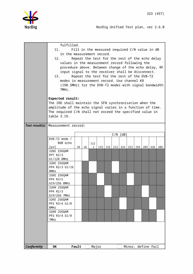
323 (457)
NorDig Unified Test plan, ver 2.6.0
Test Case Task 8:14 Subtitling – DVB Subtitling
Section NorDig Unified 7.3.2Requirement DDS:
The Display Definition Segment for a subtitle service shall be supported forservices that implement DDS, as defined in EN 300 743 [13]. Absence of a DDS implies that the display segment width shall be assumed as 720 pixels and the height as 576 lines.
The NorDig IRD shall at least be capable of decoding the following DVB subtitling services:
Object types: The handling of the object type (0x00) ‘basic object, bitmap’ shall be supported. The handling of the other object types (i.e. 0x01), ‘basic object, character’ and (0x02) ‘composite object, string of characters’) is optional.
Regions: The number of regions shall be according to the ETS 300 743 [22] specification, however a limitation in the display area due to memory restrictions is allowed. The total number of regions to handle shall be able to cover four complete subtitle rows (per frame) where one subtitle row shall be extendable to 1906 pixels * 60 pixels. The regions shall have the possibility to cover 457440 pixels per frame.
Number of objects: The number of objects shall be at least 128.
CLUT: The NorDig IRD receiver shall be able to handle at least one colour look-up table(CLUT) with a minimum of 16 entries per region and the possibility to have one colour scheme applied in each of the regions. It shall be possible to choose any 24-bit RGB colour into the 16 entries. The decoder shall be able to handle the mapping to the closest colour match if the decoder has some limitation in the colour presentation. The use of the non_modifying_colour flag is optional.
Transparency: The NorDig IRD receiver shall implement at least 5 levels of transparency; 0%(opaque), 30%, 50%, 70% and 100% (completely transparent). Implementation of additional intermediate levels of transparency is optional. Where the NorDig IRD cannot complement a particular value of semitransparency it shall replace it with the nearest value of transparency it can implement. However, if the encoded value of transparency is in the range 10%-90% it shall not be approximated as either 0% or 100% transparency. So, 9% may be approximated as 0% but 10% shall be represented with a value in the range 10% to 90%%, such as 30%. Similarly, 91% may be approximated as 100%.
Number of streams: NorDig IRD shall support at least one DVB-subtitling streams i.e. at least support decoding of one subtitling composition page while support of one simultaneously available ancillary page is optional.
IRD Profile(s) Basic, IRD, FETest procedure Purpose of test:
To check that the different DVB Subtitling services are functional.
324 (457)
NorDig Unified Test plan, ver 2.6.0
Equipment:
Expected result: Subtitling is displayed as defined in requiments.
Test result(s)Conformity OK Fault Major Minor, define fail reason in commentsComments If possible describe if fault can be fixed with software update: YES NO
Describe more specific faults and/or other information
Date Sign
MUX Exciter IRDTS Source
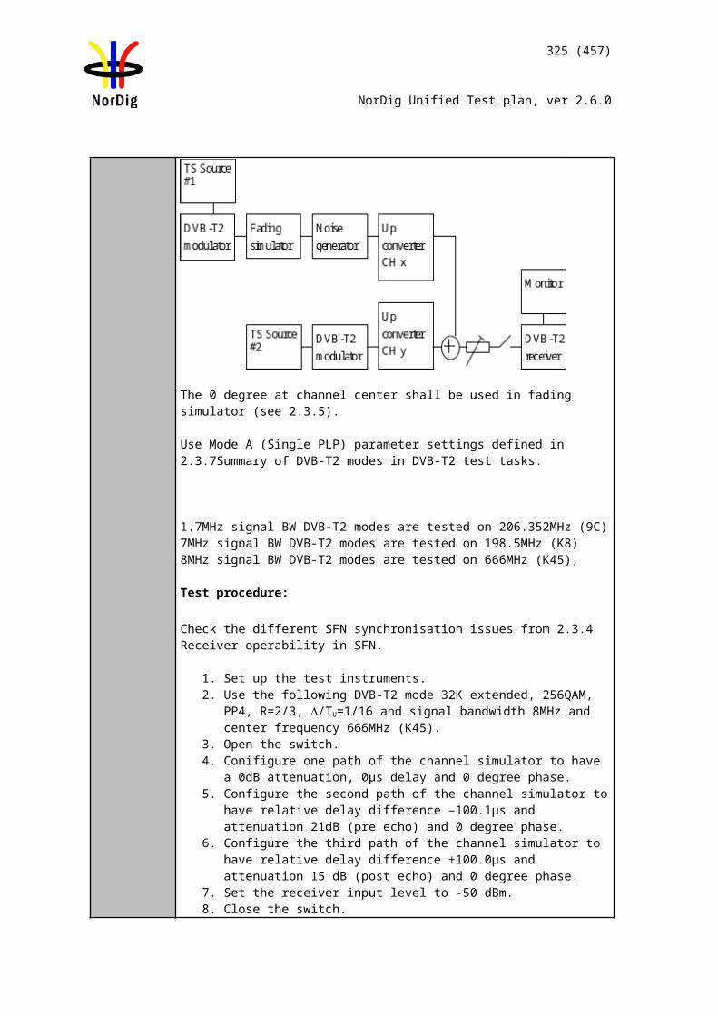
325 (457)
NorDig Unified Test plan, ver 2.6.0
2.9 Task 9: Interfaces and Signal Levels
Test Case Task 9:1 Two-way Interface
Section NorDig Unified 8.3Requirement The NorDig IRD with the Hybrid profile or an IP-based front-end shall support at least
one of the following interaction channel interfaces:1. Ethernet (IEEE 802.3 [47] (100 Base-T, Auto-sense ).2. EuroDocsis in accordance with ITU-J.122 [61] (ref IRDs with a cable front-end).3. Wireless LAN, Ethernet 802.11 n (1) [46]4. Power line [HomePlug AV Specification, IEEE 1901.2010]5. USB 2.0 or higher
IRD Profile(s) Hybrid, IRD, FETest procedure Purpose of test:
Verify functionality of interaction channel interface.
Equipment:
Manufacturer describes used test setup and test procedures.
Test result(s)Conformity OK Fault Major Minor, define fail reason in commentsComments If possible describe if fault can be fixed with software update: YES NO
Describe more specific faults and/or other information
Date Sign
Test Case Task 9:2 SCART Interface
Section NorDig Unified 8.4Requirement The NorDig STB shall (1) have one SCART Interface in accordance with EN 50049-1
[7] and EN 50157-2-1 [9].This requirement is optional from 1st January 2014 forwards.
IRD Profile(s) Basic, IRD, FETest procedure Purpose of test:
Verify that the IRD SCART interface comply with the NorDig Unified requirements.
This test is mandatory if the IRD has SCART interface.
Equipment:Test signals are created using the test bed shown below:
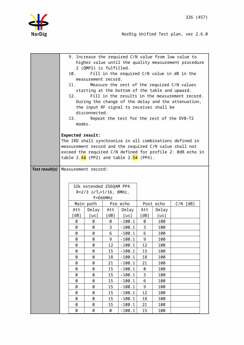
326 (457)
NorDig Unified Test plan, ver 2.6.0
The multiplex should contain a number of services with 4:3 picture aspect ratio, and one service with 16:9 aspect ratio. All services in the multiplex are descrambled before recording. And one of them contains DVB or Teletext subtitles.
If the IRD is IDTV, this test is not relevant.
Test procedure:Verify that IRD has at least one analog video and audio interface with SCART connector.
The SCART interface provides analog audio and analog video in CVBS or RGB format.
Monitor voltage on pin 8 and pin 16 on SCART when services with 4:3 and 16:9 aspect ratio video is selected.
Expected results:IRD has at least one analog video and audio output interface with SCART connector.
The SCART interface provides analog audio and analog video in CVBS or RGB video format.
Signalling in SCART is correct and shows corresponding display formats and subtitles are shown in all SCART connectors.
Test result(s)Conformity OK Fault Major Minor, define fail reason in commentsComments If possible describe if fault can be fixed with software update: YES NO
Describe more specific faults and/or other information
Date Sign
Test Case Task 9:3 HDMI interface – HD Ready
Section NorDig Unified 8.6.1Requirement The NorDig iDTV with screen diameters 30 cm and above shall have a HDMI input in-
terface in accordance with the DigitalEurope HD-Ready requirements [6] and the High Definition Multimedia Interface [40]. HDMI input interface is highly recommended for iDTV-sets with smaller screen diameters. The HDMI output interface is recommended for iDTV-sets.
The NorDig STBs shall have at least one High-Definition Multimedia Interface (HDMI) with type A output connector [40], supporting displays that comply with the DigitalEu-rope HD-Ready requirements
[6] and the High Definition Multimedia Interface [40].
IRD Profile(s) Basic, IRD, FETest procedure
Verify that the IRD has the HD Ready certificate.
Test result(s)Conformity OK Fault Major Minor, define fail reason in comments
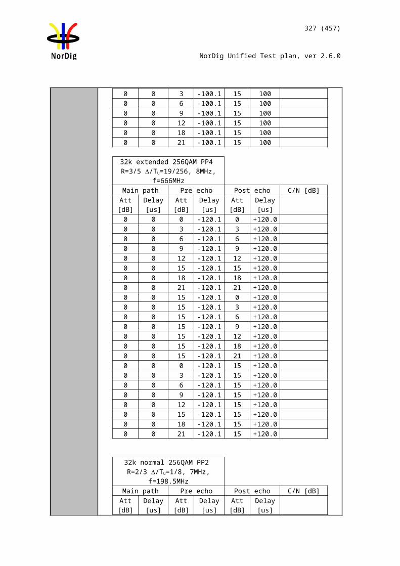
327 (457)
NorDig Unified Test plan, ver 2.6.0
Comments If possible describe if fault can be fixed with software update: YES NODescribe more specific faults and/or other information
Date Sign
Test Case Task 9:4 HDMI interface – EDID information
Section NorDig Unified 8.6.2Requirement The NorDig STB shall recognise E-EDID information provided by the display and sub-
sequently follow the below requirements.
The NorDig STB shall use 1920x1080p@50 Hz as the default output format, if sup-ported by the display.
IRD Profile(s) Basic, STB, FETest procedure
Purpose of test:To verify that the receiver is able to use the EDID information.This test is relevant for STB only.
For other IRDs having HDMI output interface this test is optional.
Equipment:
Test procedure:
Use following supported resolutions and frame rates in the HDMI analyzer for the EDID negotiation:
1280x720p50 1920x1080i25 1920x1080p50
Use following supported audio formats in the HDMI analyzer for the EDID negotiation: PCM AC-3 DTS E-AC-3
1. Set test equipment2. Power On the IRD3. Verify that the IRD can select all display parameters according the EDID
information.4. Verify that the IRD can select all audio parameters according the EDID
information.
Expected result:The IRD uses the EDID information for the video and audio parameters.
Test result(s)
MUX Exciter IRDTS Source HDMI analyzer
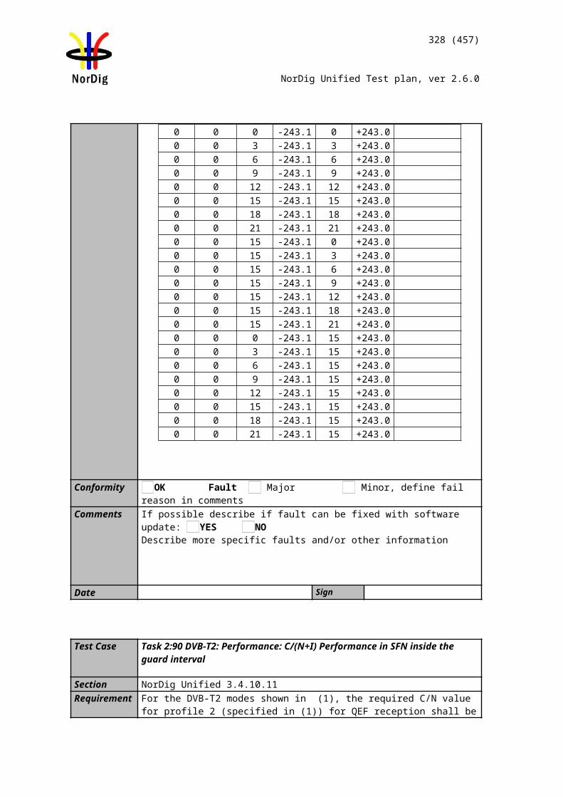
328 (457)
NorDig Unified Test plan, ver 2.6.0
Conformity OK Fault Major Minor, define fail reason in commentsComments If possible describe if fault can be fixed with software update: YES NO
Describe more specific faults and/or other information
Date Sign
Test Case Task 9:5 HDMI interface – Original format
Section NorDig Unified8.6.2Requirement By choosing an “Original Format” option, i.e. to output the same format as received, if
supported by the display. If the received format is not supported, the STB shall select the display mode providing the best possible video quality, as indicated by the E-EDID in-formation. This is to avoid the STB output to go black, if there is a mismatch between received format and display capability.
IRD Profile(s) Basic, STB, FETest procedure
Purpose of test:To verify that the receiver is able to use the EDID information.
This test is relevant for STB only.
For other IRDs having HDMI output interface this test is optional.
Equipment:
Use following resolutions and frame rates in the test stream(s): 720x576i25 1280x720p50 1920x1080i25
Test procedure:Play a test stream Power On the IRDTune to the service in test stream
Verify that video is displayed in original format if possible for the display.
Expected result:
The IRD shall negotiate the display parameters according the input signal.
Test result(s)Conformity OK Fault Major Minor, define fail reason in commentsComments If possible describe if fault can be fixed with software update: YES NO
Describe more specific faults and/or other information
MUX Exciter IRDTS Source HDMI analyzer
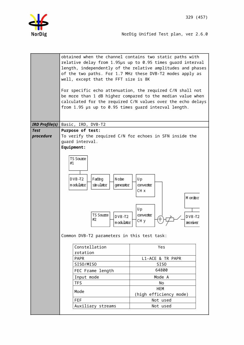
329 (457)
NorDig Unified Test plan, ver 2.6.0
Date Sign
Test Case Task 9:6 HDMI – Manual setting for resolution
Section NorDig Unified8.6.2Requirement By choosing a “Fixed Format” option, i.e. to manually set, preferably with a dedicated
knob on the remote control, the default output format from the NorDig STB to a fixed video format. The video format options shall include 1920x1080p@50Hz, 1280x720p@50Hz and 1920x1080i@25Hz.
IRD Profile(s) Basic, IRD, FETest procedure
Purpose of test:To verify that the receiver has manual setting video resolution in HDMI output.
This test is relevant for STB only.
For other IRDs having HDMI output interface this test is optional.
Equipment:
Test procedure:
1. Set the manually the display format to 1280*720p50.2. Verify that the video format is set.3. Repeat the test with 1920*1080i25 and 1920*1080p50 formats4. Fill in the test results.
Expected result:
It shall be possible to set video resolution manually in HDMI output.
Test result(s)Conformity OK Fault Major Minor, define fail reason in commentsComments If possible describe if fault can be fixed with software update: YES NO
Describe more specific faults and/or other information
Date Sign
Test Case Task 9:7 HDMI – Signal protection
Section NorDig Unified8.6.4Requirement HDMI interfaces that can output content that is originated from a DVB input
signal shall support the High-bandwidth Digital Content Protection (HDCP) [39].The received service may be flagged with a need for content protection or not
MUX Exciter IRDTS Source HDMI analyzer
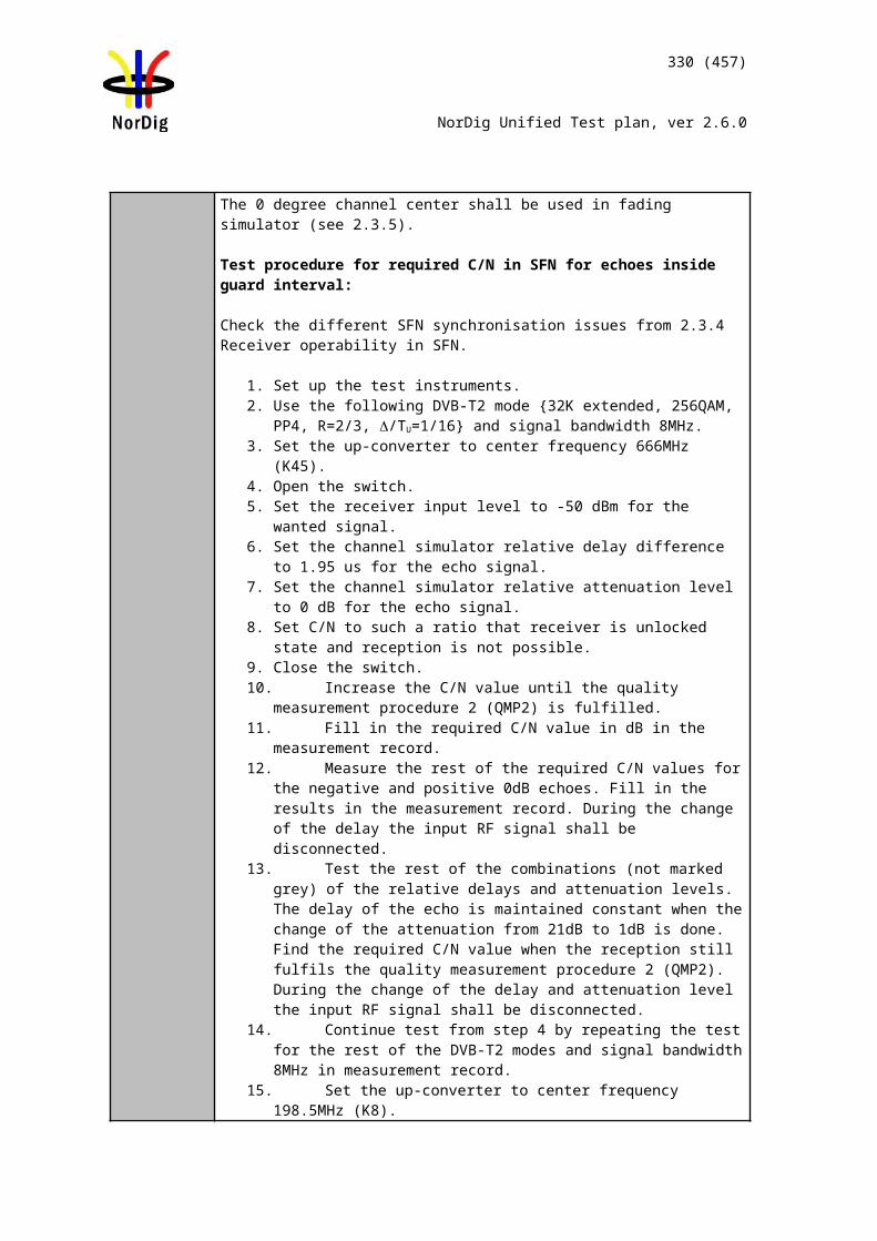
330 (457)
NorDig Unified Test plan, ver 2.6.0
(CP “ON” or “OFF”) via either the PMT-table or the CA-system or both, as specified by the relevant network/CA-operator.
Note 1: Disabling of HDCP is optional
IRD Profile(s) Basic, IRD, FETest procedure Purpose of test:
To verify that the receiver is able set the status HDCP according the signal protection scheme.
This test is mandatory if the IRD has HDMI output interface.
Equipment:
Test procedure:1. Setup the equipment2. Set the content protection mode to one by one each mode in table below3. Fill in test results
Expected result:
It shall be possible to set the content protection mode.
Test result(s)
Mode IRD actions CA-system PMT-table NOK or OK
1 HDCP may be disabled for this service regardless of HDCP user setting(Return to HDCP-user setting when leaving this service)
Note: This requirement is optional
HDCP Not wanted
0x00(HDCP Not
wanted)
2 HDCP shall be enabled for viewing this service(Return to HDCP-user setting when leaving this service)
HDCPWanted
0x00(HDCP Not
wanted)
3 Content protection is not required. HDCP may be enabled or disabled
CP Not needed
0x01(Not needed)
4 Content protection is required.HDCP shall be enabled for viewing this service
CPRequired
0x01(Not needed)
5 SD service: HDCP may be enabled or disabledHD service: HDCP shall be enabled this service
CPNot needed
0x02(cond’al require-
ment)
6 Content protection is required.HDCP shall be enabled for viewing this service
CPRequired
0x02(cond’al require-
ment)
7 Content protection is required.HDCP shall be enabled for viewing this service
CPNot needed
0x03(CP required)
MUX Exciter IRDTS Source
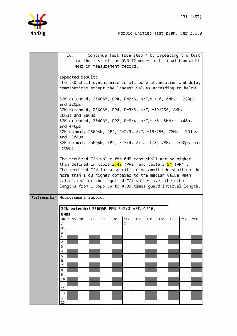
331 (457)
NorDig Unified Test plan, ver 2.6.0
8 Content protection is required.HDCP shall be enabled for viewing this service
CPRequired
0x03(CP required)
Conformity OK Fault Major Minor, define fail reason in commentsComments If possible describe if fault can be fixed with software update: YES NO
Describe more specific faults and/or other information
Date Sign
Test Case Task 9:8 Analogue video interface(Option)
Section NorDig Unified8.6.5Requirement The NorDig STB shall provide down-converted versions of the received HDTV signals
via analogue video interfaces, where the output signal is down-converted to SDTV for-mat, see section 5.11.The NorDig IRD may provide analogue audio output signals via the SCART and/or the RCA connectors, as specified in sections 8.4, 8.5.1 and 8.5.2.
IRD Profile(s) Basic, IRD, FETest procedure
Purpose of test:To verify that the IRD always outputs SD (576i) on the SCART or any other analogue video output (Y, Pb, Pr, RF-PAL or CVBS) connector.
This test is relevant only for IRD with analoque video output interface.
Equipment:
The TS shall contain a service which has a video component that Change between 1280 x 720p@50Hz and 1920 x 1080i@25Hz video
resolution
Test procedure:1. Set up the test environment according to above.2. Play out the transport stream with alternating video resolutions 1280 x
720p@50Hz and 1920 x 1080i@25Hz3. Make a channel search on the IRD4. Verify that the SCART or any other analoque video output has always SD
(576i) regardless of HDMI setting and resolution. 5. Verify that down-converted 1:1 pixel aspect ratio resolutions are displayed
as 16:9 letterbox on 4:3 displays.
Expected result: That the IRD only outputs SD (576i) on SCART any other analoque video output (i.e. not higher than 576i).
MUX Exciter IRDTS Source
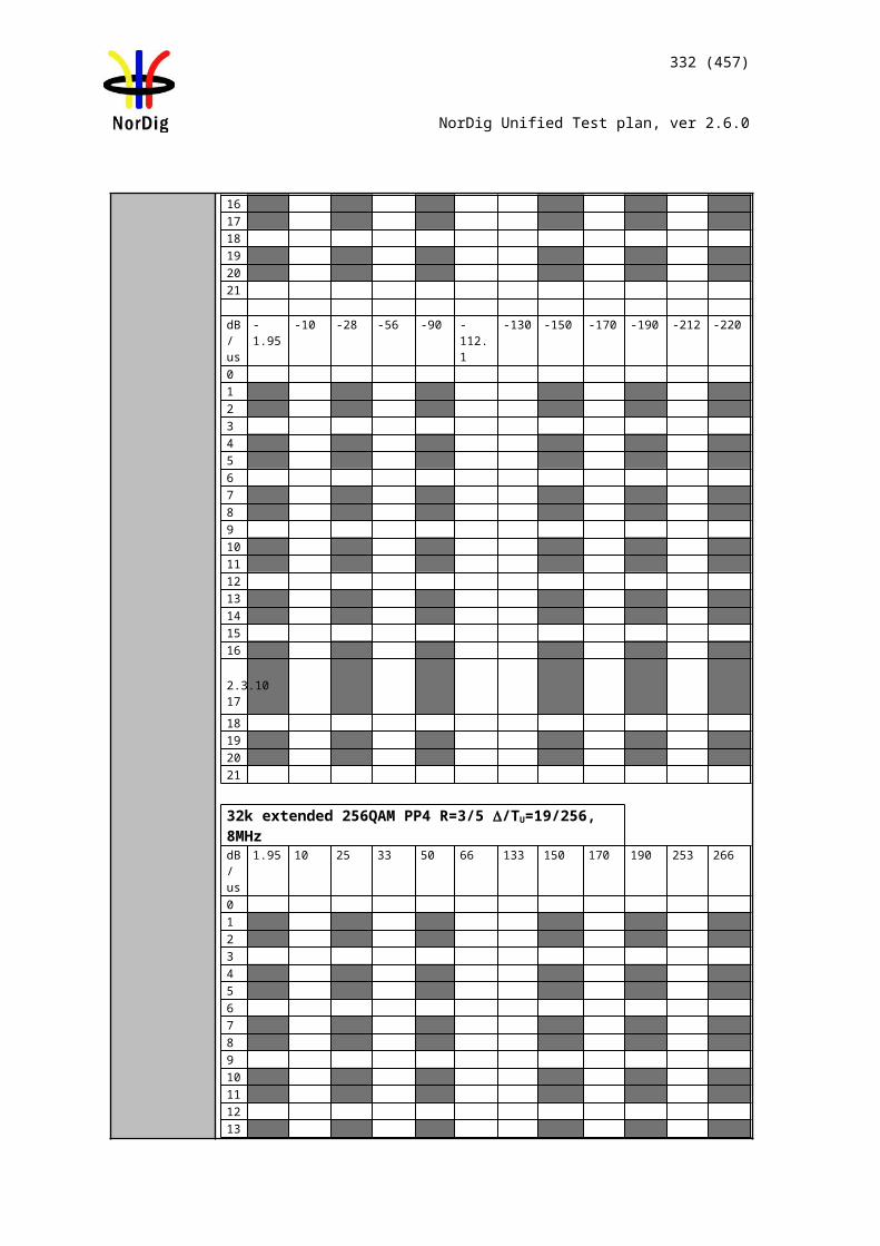
332 (457)
NorDig Unified Test plan, ver 2.6.0
Test result(s)Conformity OK Fault Major Minor, define fail reason in commentsComments If possible describe if fault can be fixed with software update: YES NO
Describe more specific faults and/or other information
Date Sign
Test Case Task 9:9 Remote Control Function Keys
Section NorDig 8.7.2Requirement The remote control for the NorDig IRD shall include the following functions (the
labelling names that are used in Figure 8.1 are shown below within square brackets for each function), associated with input events. An input event may be associated with a physical key or a logical (e.g. on-screen) key, where the “logical key” is associated with the same function as specified for the corresponding physical key.
The NorDig IRD remote control shall include 10 digit keys, labeled 0-9
The NorDig IRD’s remote control shall include the following keys for digital TV func-tions:o [←, ↑, →, ↓] – A navigation or pointing system for navigation on the OSDo OK [OK] – a function that selects or confirms current choice or statemento Multifunctional keys [•, •, •, •] – four colour-coded keys for non-dedicated function-s.The colours shall be red, green, yellow and blueo Text [Text] –This function displays the teletext as defined in section 7.1 or a DigitalSuper Teletext if present.
IRD Profile(s) Basic, IRD, FETest procedure
Test procedure:
Check the manufacturer technical specification / compliance list or verify the remote control functions.
Expected result:
The minimum hardware requirement is fulfilled.
Test result(s)Conformity OK Fault Major Minor, define fail reason in commentsComments If possible describe if fault can be fixed with software update: YES NO
Describe more specific faults and/or other information
Date Sign
Test Case Task 9:10 Remote Control Function Keys for PVRSection NorDig 8.7.2.4Requirement The NorDig PVR IRD's remote control shall include the following keys for PVR
functionality:o List of recordings [PVR List] – opens a screen with list of recordings (can be bothhistory and booked).
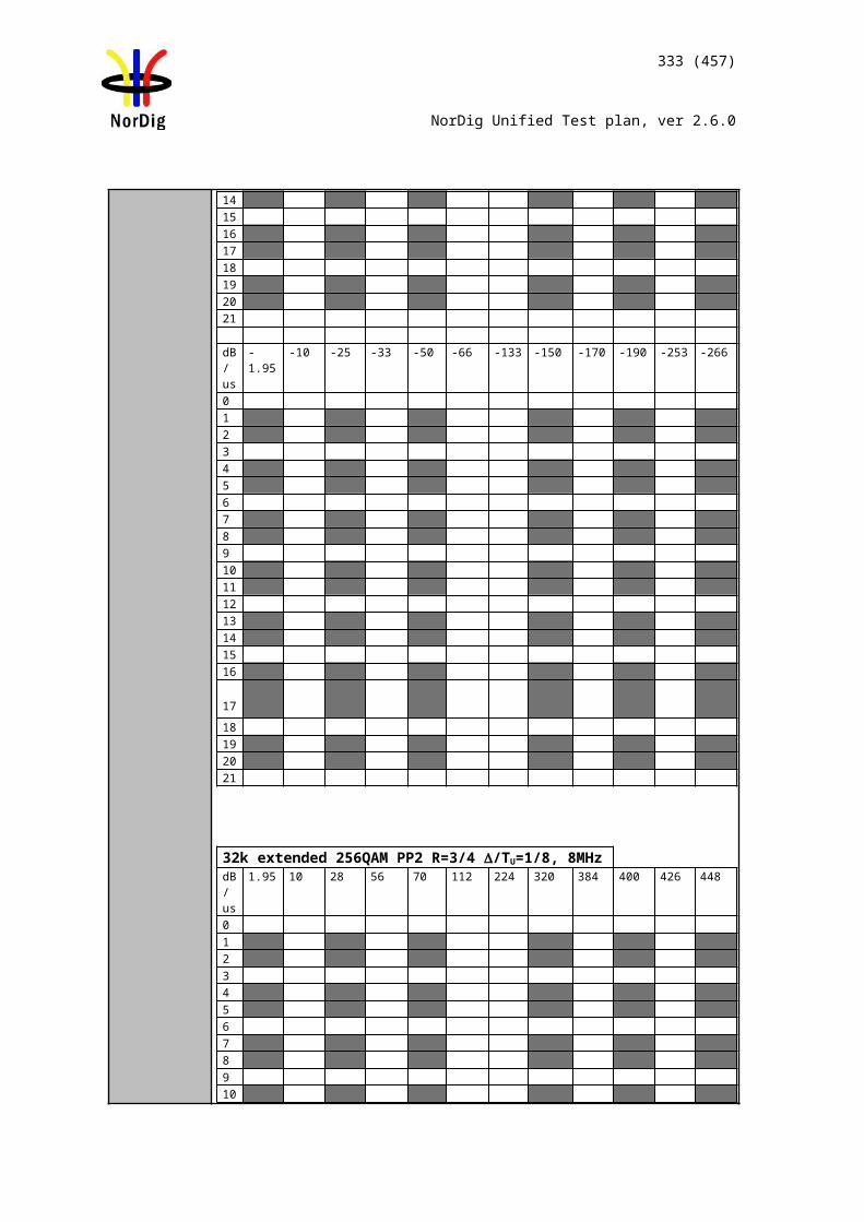
333 (457)
NorDig Unified Test plan, ver 2.6.0
o OTR [OTR] – One-Touch-Recordingo Record [Rec] – Start manual recording / start recording of present event.o Timeshift [t.shift] – "pause" live TV (timeshift)o Pause [Pause] – pause Playback of recording.o Play [Play] – start playing timeshift TV / start playback of recording.o Stop [Stop] – stop recording / stop timeshift / stop playback.o Fast Forward [F.fwd] – fast forward of the timeshift or recording (with differentspeeds).o Fast Rewind [F.rwd] – fast rewind of the timeshift or recording (with different speeds).
IRD Profile(s) Basic, PVR, IRD, FETest procedure
Test procedure:
Check the manufacturer technical specification / compliance list or verify the remote control functions.
Expected result:
The minimum hardware requirement is fulfilled.
Test result(s)Conformity OK Fault Major Minor, define fail reason in commentsComments If possible describe if fault can be fixed with software update: YES NO
Describe more specific faults and/or other information
Date Sign
Test Case Task 9:11 Remote Control Key event mapping for NorDig HybridSection NorDig 8.7.2.6Requirement The NorDig Hybrid IRD shall generate (HbbTV) events according to Table 8.3 when a
key is pressed on the NorDig IRD remote control.IRD Profile(s) Hybrid, PVR, IRD, FETest procedure
Test procedure:
Check the manufacturer technical specification / compliance list or verify the remote control functions.
Expected result:
The minimum hardware requirement is fulfilled.
Test result(s)Conformity OK Fault Major Minor, define fail reason in commentsComments If possible describe if fault can be fixed with software update: YES NO
Describe more specific faults and/or other information
Date Sign
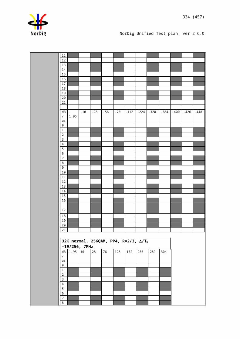
334 (457)
NorDig Unified Test plan, ver 2.6.0
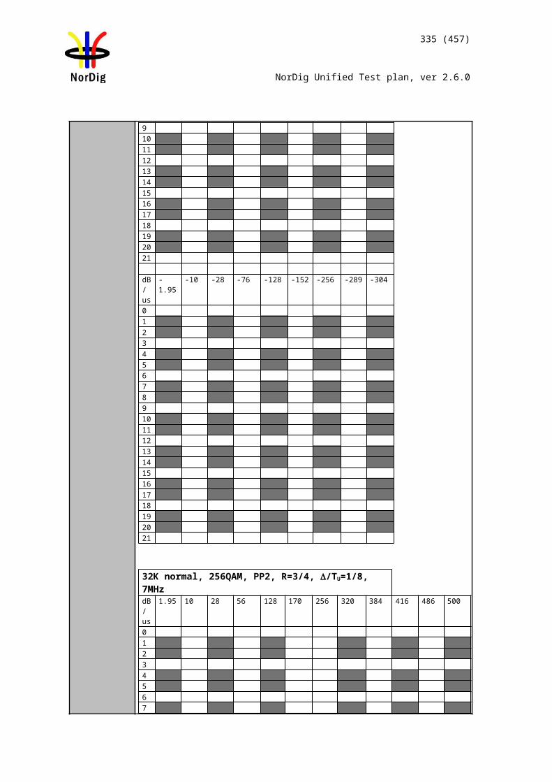
335 (457)
NorDig Unified Test plan, ver 2.6.0
2.10 Task 10: Interfaces for Conditional Access
Test Case Task 10:1 Use of Common Interface
Section NorDig Unified 9.2Requirement The Common Interface can be used for conditional access and other purposes. A
conditional access (CA) module may be connected to the Common Interface of the NorDig IRD in order to provide access control of the incoming services.The Common Interface may be used with CA-modules that comply with the Common Interface Plus specification, see refCI Plus specification; such modules are referred to as CIP-CAM.The Common Interface may be also be used with CA-modules that comply with the DVB Common Interface specification, see EN 50221; such modules are referred to as DVB-CAM.
Each CI-slot of the NorDig IRD shall (1&2) be in compliance with the Common Interface Plus specification. Each CI-slot shall support both CIP-CAMs and DVB-CAMs in accordance with with the interoperability matrix that is specified in the CI Plus specification, table 4.1.
IRD Profile(s) Basic, IRD, FETest procedure The Test procedure shall (provisionally) be based on existing interface test
specifications for at least the most common CAMs supporting both DVB-CAM and CIP-CAM.
The IRD manufacturer shall describe the used test procedure.Test result(s) The test results shall show that the IRD is fully compatible with CAM, when the CAM
is equipped for at least one of the CA-systems used in the Nordic area.Conformity OK Fault Major Minor, define fail reason in commentsComments If possible describe if fault can be fixed with software update: YES NO
Describe more specific faults and/or other information
Date Sign
Test Case Task 10:2 Smart Card Interface
Section NorDig Unified 9.3.2Requirement The NorDig IRD shall include at least one (1) embedded smart card reader for use with
conditional access and/or other applications.The smart card interface shall comply with ISO/IEC 7816 Part 1-3 [60]. The NorDig IRD does not need to support synchronous cards.
IRD Profile(s) Basic, IRD, FE
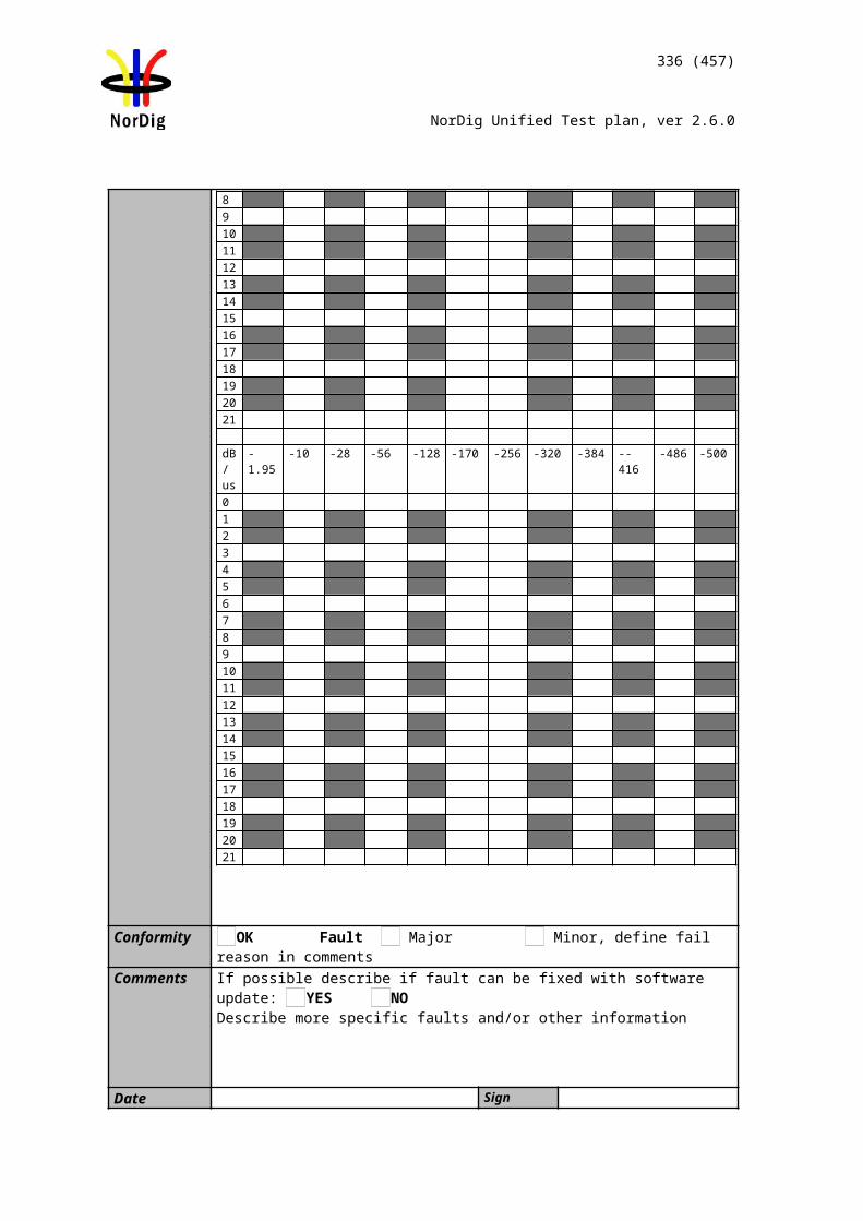
336 (457)
NorDig Unified Test plan, ver 2.6.0
Test procedure Purpose of test:Verify functionality of smart card interface.
This test is mandatory depending of the network operator or operator requirement.
Equipment:Test bed providing transport streams with CA-scrambled services.IRD under test.
Test procedure:Select a CA-scrambled service and observe decoded picture/sound.
Test result(s)Conformity OK Fault Major Minor, define fail reason in commentsComments If possible describe if fault can be fixed with software update: YES NO
Describe more specific faults and/or other information
Date Sign
This update replaces 2.11 task 11 (old chapter is deleted from this document)
2.11 Task 11: The System Software Update
2.11.1 SSU testing GeneralThe NorDig IRD shall provide a software download mechanism that enables download of sytem software to replace existing software. Delivery alternatives (optional or mandatory depending on the connectable status of the IRD) are:- OTA (#D1 and #D2): “Over-the-Air”, refers here to over the broadcast channel (via terrestrial, cable, satellite or managed IPTV interface) .- OTA Notification (#D3): refers here to search/get notification over the broadcast channel and download from Internet and/or USB. - OTN (#D4): “Over-the-Network”, refers here to over the Internet channel (via IRD’s two-way interface). - USB (#D5): “Local”, refers to download from the local interface.
During the SSU testing both upgrade and downgrade are are performed with a special mode/SW used for the downgrade process (normally not available with production software/public SSU). Alternatively the manufacturer must deliver several physical samples that can each be upgraded once.
2.11.2 Test equipment summaryTo configure the minimum test setup described in these test procedures, the test setup seen inFigure 2 can be used.
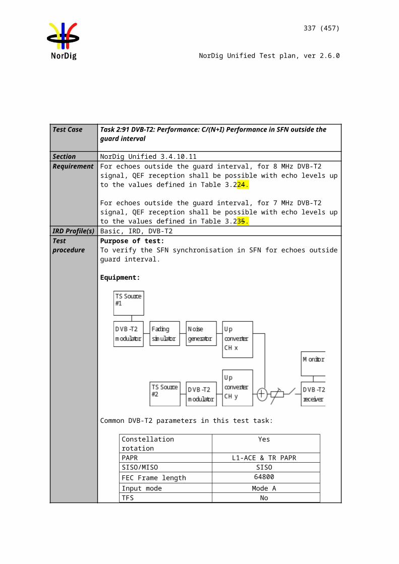
337 (457)
NorDig Unified Test plan, ver 2.6.0
Figure 2. Generic test setup for SSU / CI+ CAM test procedures
Note! The equipment needed may vary depending on the system used and can be purchased from many vendors even in a compact all-in-one unit. However, most of the tests can done using one general test setup.
2.11.2.1 Broadcast SSU (OTA)The OTA-SSU / CI+ CAM update service is carried within a transport stream. The TS must contain the correct type of signaling information in order for the IRD to detect the correct OTA-SSU / CI+ CAM update service. The following sections describe minimum signaling information.
The NIT must contain:
Linkage_descriptor 0x4A to DVB SSU service using linkage_type 0x09.
Example for linkage_descriptor for IRD system download located at TSID/ONID 0x0456/0x22F1.
Descriptor_tag 0x4ATransport_stream id 0x0456Original_network_id 0x22F1Service_id 0x1194Linkage_type 0x09OUI *)selector_bytesprivate_data_byte **)
*) DVB OUI or manufacturer specific OUI**) The private_data_byte shall be used as specified in the DVB Data Download Specification; Part 1: Simple Profile. (ETSI TS 102 006 v1.3.1 )
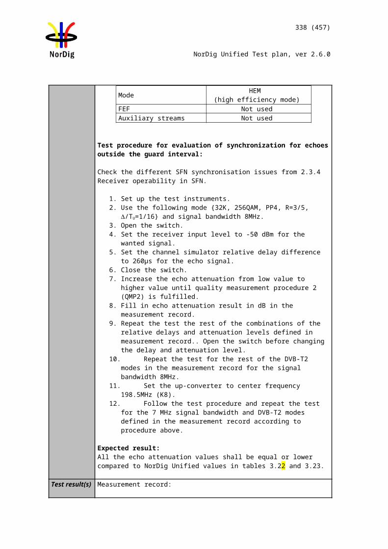
338 (457)
NorDig Unified Test plan, ver 2.6.0
The PMT must contain:(The descriptor shall be placed in the component loop of the PSI PMT table.)
Data_broadcast_id_descriptor
descriptor_tag 0x66data_broadcast_id 0x000Aid_sector_bytes *)OUI **)update_type ***)update_versioning_flagupdate_versionselector_bytesprivate_data_bytes
*) The id_sector_bytes shall be used as specified in the DVB Data Download Specification (ETSI TS 102 006).**) The OUI value in the PMT shall match the OUI value in the NIT linkage to SSU descriptor.***) Update_type, use value below specified for simple or enhanced profiles;
proprietary update solution (not allowed). 0x0standard update carousel (i.e. without notification table) via broadcast. 0x1system software update carousel with notification table (UNT) both available via broadcast.
0x2
system software update signaled via broadcast UNT,update available from the return channel.
0x03
system software update signaled via broadcast UNT,update available from the Internet.
0x04
Reserved for future use. 0x5 – 0xFF
The UNT must contain: Signaling of UNT is relevant in case of the data_broadcast_id_descriptor parameter update_type is set to 0x02 in PMT.
The parameters for different descriptors in UNT are specified below:
descriptor_tag 0x4Btable_id 0x01OUI 1)
processing_order 2)
common_descriptor_loop 3)
target_descriptor_loop 4)
operational_descriptor_loop 5)
1) The OUI value in the PMT shall match the OUI value in the NIT linkage to SSU descriptor.2) Depending on the SSU OTA mechanism.3) common_descriptor_loop carries information which is intended for descriptors which apply to all platform/target devices listed in target_descriptor_loop and operational_descriptor_loop. 4) target_descriptor_loop can contain descriptor:
target_serial_number_descriptor 5) operational_descriptor_loop can contain descriptors:
scheduling_descriptor
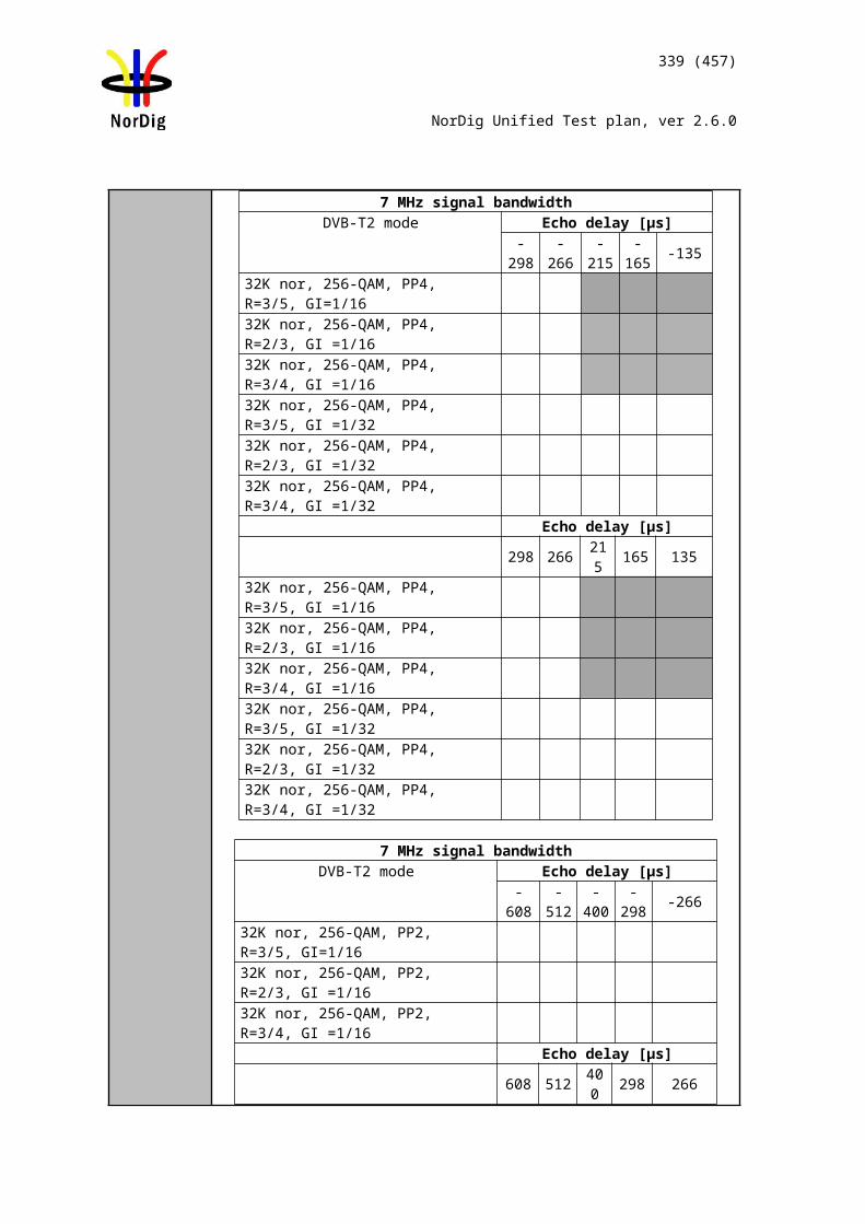
339 (457)
NorDig Unified Test plan, ver 2.6.0
Examples for scheduling_descriptordescriptor_tag 0x01start_date_timeend_date_timefinal_availability 0periodicity_flagperiod_unitduration_unitestimated_cycle_time_unitperioddurationestimated_cycle_time
update_descriptor ssu_location_descriptor message_descriptor ssu_subgroup_association_descriptor private_data_specifier_descriptor
See more details regarding settings in DVB Data Download Specification (ETSI TS 102 006).
NorDig T2-IRD SSU OTA in DVB-T2 system The SSU stream is broadcast with parameter settings of PLP_ID = 1, T2_System_Id = 1 and Cell_Id =
1 in a single PLP mode.
2.11.2.2 Network SSUThe IRD manufacturer must ensure that the published OTN software contains the correct type of signaling information in order for the IRD to detect the correct SSU.The IRD manufacturer shall ensure a software upgrade is available over the public Internet, the test is not valid if the SSU is just locally published in a lab enviroment.For the OTN testing the IRD must connect to the Internet by LAN cable or via Wi-Fi through a local router or access point.The Internet connection during testing should reflect the country settings of the IRD under test, e.g. using a VPN tunnel to simulate ip connection from the same country as the country setting of the IRD.
2.11.3 Test cases
Test Case Task 11:1 IRD System software update using DVB SSU simple profile
Section NorDig Unified 10.1, 10.2,10.5, 12.2.6 and 16.4Requirement The NorDig IRD shall provide a software download mechanism
that enables download of system software, to add a new system software or replace an existing system software.
The upgrade of NorDig IRD software shall be initiated by the user (by update user preference setting and/or by user interaction). The user shall be able to choose the update approach for the IRD (see 10.2.1 in IRD spec) and the user shall be able to disable any automatic update. The factory default shall
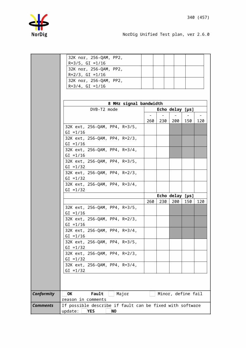
340 (457)
NorDig Unified Test plan, ver 2.6.0
be a value that disables Fully Automatic mode.
In cases where the user is prompted to confirm an update, the user shall be able to confirm or to abort/postpone the update (for example with a Yes and No option). If the user selects to abort/postpone an available update or by other ways cancel an available update, the NorDig IRD shall remind the user as stated in section 10.1.6 in IRD spec.
The NorDig IRD shall be provided with a mechanism ensuring that only newer software versions than the existing System Software are accepted.
If the NorDig IRD System software is corrupt (due to normal operation of the IRD or due to updating the system software), the IRD manufacturer shall provide a backup mechanism, either on local storage or via download, which can make the IRD operational again.
The NorDig IRD supporting SSU via broadcast channel shall support the DVB SSU simple profile using the signalling in NIT, BAT and PMT, in accordance with the DVB-SSU specification . The Linkage descriptor in the NIT table, for linking to the SSU service is defined in NorDig Unified IRD specification section 12.2.6.
IRD Profile(s) All IRDs that are using OTA SSU simple profileTest procedure Purpose of test:
To verify the IRD system software update process in broadcast channel using DVB SSU simple profile.
The SSU end user functionality is not tested in this case. It is tested in Error: Reference source not found6 SSU end user functionality.
This test is convenient to do parallel with Error: Reference source not found6 SSU end user functionality.
Equipment:Test setup described in Error: Reference source not found2 Error: Reference source not found
For the testing three IRD SSU software is needed, “SW v1“,“SW v2“ and “SW v3“, (“SW v1“ as starting point, “SW v2“ for testing upgrading and “SW v3“ for testing ˮnon-downgradingˮ).
IRD manufacturer shall ensure that software upgrade (“SW v1”) , (“SW v2”) and (“SW v3”) is available for the test lab.
Two approaches for the SSU testing, either via using:- one single IRD with possibility to upgrade and downgrade the SW by other means plus SSU sw images of “SW v1“ , “SW v2“ and “SW v3“. - alternative via using multiple IRDs. Two IRDs with software “SW v1“ and one IRD with software “SW v3“.
Selection of two different ONID for different networks corresponding country1 and country2 in the test procedure.
341 (457)
NorDig Unified Test plan, ver 2.6.0
Test procedure:
1. Configure three outgoing download streams from the system software source. The system software PID, PMT PID and SID may not conflict with each other.
2. Configure the multiplexer to transmit three outgoing system software download streams within TS on the frequency f1. The system software PID, PMT PID and SID may not conflict with each other. (Simulates three system software streams.)
3. Configure linkage_descriptor for the two system software download streams not to be suitable for the IRD under test. The linkage_descriptor parameters for the third download stream shall be suitable for the IRD under test. The third system software download stream shall be the last in order.
4. Fill in the test results which parameters are unmatching with the IRD under test.
5. For the frequency f2 configure linkage_descriptor to refer to the frequency f1 with suitable parameters for the over-the-air download. (Simulates frequency change).
6. Make sure the IRD has “SW v1” installed.7. Perform factory reset to the IRD, complete the “first time” installation and
check that all the services are possible to receive.8. Tune the IRD to a service on the frequency f1.9. Fill in the test results if the IRD has a setting for automatic search and it is set
to “auto search”.
10. Initiate the download. 11. Verify that the software in the IRD is updated to “SW v2”.12. Fill in the test protocol.
13. Downgrade IRD software to “SW v1” .14. Tune the IRD to a service on the frequency f2.15. Initiate the download again. 16. Verify that the software in the IRD is updated to “SW v2”.17. Fill in the test protocol.
18. Upgrade IRD software to “SW v3” .19. Perform factory reset to IRD and check that all the services are possible to
receive.20. Initiate the download again. Verify that no software update occurs.
21. Downgrade IRD software to “SW v1” .22. Initiate the download again.23. During the update process (step 10), remove the power cable to corrupt the
installation of the system software to corrupt the downloading of the system software.
24. Wait 10 seconds and then re-insert the power cable. 25. Verify that the IRD is still usable. 26. Fill in the test protocol. Fill in extended information in the comments section if
the IRD ends up in an error state. Error messages etc.
27. Initiate the download again. 28. Plug out the antenna cable. (Simulates RF disturbances).29. Plug in the antenna cable.
Fill in the test protocol. Fill in extended information in the comments section if the IRD ends up in an error state. Error messages etc.
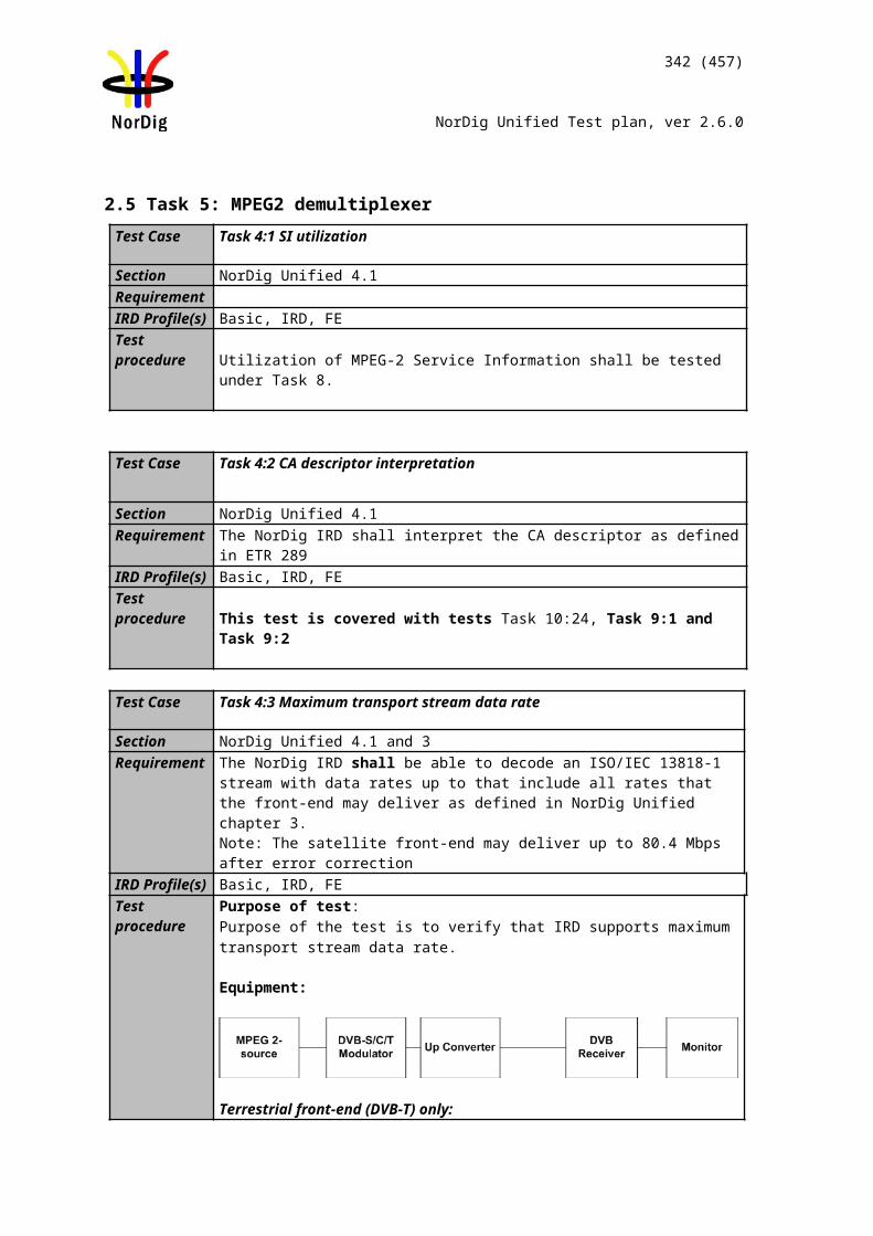
342 (457)
NorDig Unified Test plan, ver 2.6.0
30. Verify which ONID values correspond country1 and country2 settings in IRD.31. Make sure that the IRDs country setting is equal to country2.32. Configure the TS from f1 carrying the SSU service so that the ONID is equal to
country1.33. Configure the TS from f2 so that the ONID is equal to country2.34. Fill in the test protocol which ONID values are broadcasted in TS in f1
(country1) and f2 (country2).35. Fill in the test protocol which country settings are selected in the IRD.36. Control that the IRD will not download and install the SSU. 37. Fill in the test protocol.
Expected result: IRD performs a software update from DVB SSU simple profile OTA broadcast available stream.
Test result(s)
Unmatched SSU stream number Unmatched parameter name#1
#2
ONID valueONID value in TS in f1 (country1)
ONID value in TS in f2 (country2)
Test points OK or NOK9 Does IRD have a setting for automatic SSU search
set by default to “auto search” ?10- 12 The correct system software on the frequency f1 is
upgraded.13 – 17 The correct system software, when initiated on
frequency f2, is upgraded.18 - 20 Ensure that only newer versions are downloaded21 – 26 IRD starts after electric break using old (working)
software.27 – 29 The IRD clarifies the RF signal reception
disturbancies under OTA download. It has current software.
30 – 37 The IRD does not download or install the SSU from other ONIDs than the ONID that matches the country setting in the IRD.
343 (457)
NorDig Unified Test plan, ver 2.6.0
Conformity OK Fault Major Minor, define fail reason in commentsComments If possible describe if fault can be fixed with software update: YES NO
Describe more specific faults and/or other information
Date Sign
Test Case Task 11:2 IRD System software update using DVB SSU enhanced profile - scheduling
Section NorDig Unified 10.1, 10.2 and 10.5Requirement The NorDig IRD supporting SSU via broadcast channel shall provide a software
download mechanism in accordance with the DVB SSU specification , the IRD shall support the SSU Simple Profile and the parts of SSU Enhanced Profile that are specified below.
The test requirements are the same as for DVB SSU simple profile in Task 11:1 with the addition of scheduled tasks.
The NorDig IRD supporting SSU download via broadcast channel shall support the DVB SSU UNT Enhanced profile using the signalling in NIT, BAT, PMT, and UNT, in accordance with the DVB-SSU specification. The Linkage descriptor in the NIT table, for linking to the SSU service is defined in section 12.2.6. The descriptors of the UNT Enhanced profile are specified in Section 12.7.
IRD Profile(s) All IRDs that are using OTA SSU enhanced profileTest procedure Purpose of test:
To verify the IRD system software update process in broadcast channel using DVB SSU enhanced profile.
The SSU end user functionality is not tested in this case. It is tested in Error: Reference source not found6 SSU end user functionality.
This test is convenient to do parallel with Error: Reference source not found6 SSU end user functionality.
Equipment:Test setup described in 2.11.2 Error: Reference source not found
For the testing three IRD SSU software is needed, “SW v1“,“SW v2“ and “SW v3“, (“SW v1“ as starting point, “SW v2“ for testing upgrading and “SW v3“ for testing ˮnon-downgradingˮ).
IRD manufacturer shall ensure that software upgrade (“SW v1”) , (“SW v2”) and (“SW v3”) is available for the test lab.
Two approaches for the SSU testing, either via using:- one single IRD with possibility to upgrade and downgrade the SW by other means plus SSU sw images of “SW v1“ , “SW v2“ and “SW v3“. - alternative via using multiple IRDs. Two IRDs with software “SW v1“ and one IRD with software “SW v3“.
Selection of two different ONID for different networks corresponding country1 and
344 (457)
NorDig Unified Test plan, ver 2.6.0
country2 in the test procedure.
Test procedure:
Refer to Error: Reference source not found but use DVB SSU enhanced download stream instead.
1. Configure three outgoing download streams from the system software source. The system software PID, PMT PID and SID may not conflict with each other.
2. Configure the multiplexer to transmit three outgoing system software download streams within TS on the frequency f1. (Simulates three system software streams.)
3. Configure linkage_descriptor for the two system software download streams not to be suitable for the IRD under test. The linkage_descriptor parameters for the third download stream shall be suitable for the IRD under test. The third system software download stream shall be the last in order.
4. Fill in the test results which parameters are unmatching with the IRD under test.
5. Configure UNT inclusive scheduling_descriptor by creating schedule with three scheduling descriptors, one in the past and two in the future for the system download streams.
6. For the frequency f2 configure linkage_descriptor to refer to the frequency f1 with suitable parameters for the over-the-air download. (Simulates frequency change).
7. Make sure the IRD has “SW v1” installed.8. Perform factory reset to the IRD, complete the “first time” and check that all
the services are possible to receive. 9. Fill in the test protocol if the IRD support automatic search and it is set to
“automatic search” by default.
10. Tune the IRD to a Tv service on f1, turn off the IRD and wait until IRD is standby.
11. Turn on the IRD from standby.12. A message shall be displayed telling that a new software is available at the
time specified in the scheduling_descriptor. The IRD shall find the nearest available scheduled time.
13. Verify that the “EXIT or abort” option works by verifying that no download occur at the scheduled time.
14. Turn off the IRD and wait until IRD is standby.15. Turn on the IRD from standby.16. Verify that the “Yes or OK” option works by verifying that download
occur at the scheduled time. 17. Verify that the software in the IRD is updated to “SW v2”.
18. Downgrade IRD software to “SW v1” . 19. Perform 11,12,13,14,15,16,17,18 but Tune the IRD to a Tv service on f2,
turn off the IRD and wait until IRD is standby.
20. Upgrade IRD software to “SW v3” or use “IRD”.21. Perform factory reset to the “IRD” and check that all the services are possible
to receive.22. Initiate the download again. Verify that no software update occurs.

345 (457)
NorDig Unified Test plan, ver 2.6.0
23. Enhanced profile with software for the IRD under test, scheduled active now, with more than one schedule_descriptor in UNT.
24. Initiate a manual download from the menu.25. A message shall be displayed telling that a new software is available right
now.26. Verify that both OK and EXIT works.27. Reset the IRD28. Perform 23,24,25,26 but initiate the download via a background/standby
search.
29. Downgrade IRD software to “SW v1” .30. Verify which ONID values correspond country1 and country2 settings in IRD.31. Make sure that the IRDs country setting is equal to country2.32. Configure the TS from f1 carrying the SSU service so that the ONID is equal to
country1.33. Configure the TS from f2 so that the ONID is equal to country2.34. Fill in the test protocol which ONID values are broadcasted in TS in f1
(country1) and f2 (country2).35. Fill in the test protocol which country settings are selected in the IRD.36. Initiate a download.37. Control that the IRD will not download and install the SSU.
38. Downgrade IRD software to “SW v1” .39. Initiate the download again.40. During the update process remove the power cable to corrupt the installation of
the system software to corrupt the downloading of the system software. 41. Wait 10 seconds and then re-insert the power cable. 42. Verify that the IRD is still usable. 43. Fill in the test protocol. Fill in extended information in the comments section if
the IRD ends up in an error state. Error messages etc.
44. Initiate the download again. 45. Plug out the antenna cable. (Simulates RF disturbances).46. Plug in the antenna cable.47. Fill in the test protocol. Fill in extended information in the comments section if
the IRD ends up in an error state. Error messages etc.
48. Fill in the test protocol.
Expected result:
IRD performs a system software update from DVB SSU enhanced profile OTA broadcast for future available stream.
Test result(s)
Unmatched SSU stream number Unmatched parameter name#1
#2
ONID value
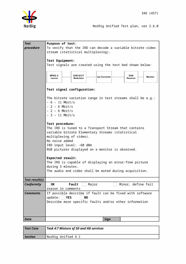
346 (457)
NorDig Unified Test plan, ver 2.6.0
ONID value in TS in f1 (country1)
ONID value in TS in f2 (country2)
Test points OK or NOK9 Does the IRD have a setting for automatic SSU
search and it is set to “automatic search” by default?
11-17 Does the IRD display a pop-up message telling the closest time and date for the available OTA ?
11-17 Does the pop-up message have selection “OK to download” and “EXIT to abort” ?
11-17 Selecting EXIT doesn’t upgrade the IRD at specified time and date.
11-17 Does the IRD upgrade the future available software at available time and date when turned off and turned on ?
18-19 Does the IRD display a pop-up message telling the closest time and date for the available OTA ?
18-19 Does the pop-up message have selection “OK to download” and “EXIT to abort” ?
18-19 Selecting EXIT doesn’t upgrade the IRD at specified time and date.
18-19 Does the IRD upgrade the future available software at available time and date when turned off and turned on ?
20-22 IRD has a mechansim that ensures only newer software version than the existing System Software is accepted
23-26 Does the IRD upgrade when the new sw is available right now when searching, From menu .
27-28 Does the IRD upgrade when the new sw is available right now when searching, standby.
29-37 The IRD does not download or install the SSU from other ONIDs than the ONID that matches the country setting in the IRD.
38-43 IRD starts after electric break using old (working) software.
44-47 The IRD clarifies the RF signal reception disturbancies under OTA download.
Conformity OK Fault Major Minor, define fail reason in commentsComments If possible describe if fault can be fixed with software update: YES NO
Describe more specific faults and/or other information
Date Sign
Test Case Task 11:3 IRD System software update using DVB SSU NotificationSection NorDig Unified 10.1, 10.2, 10.3, 10.5 and 12.7Requirement For this approach the NorDig IRD shall automatically perform a regular search
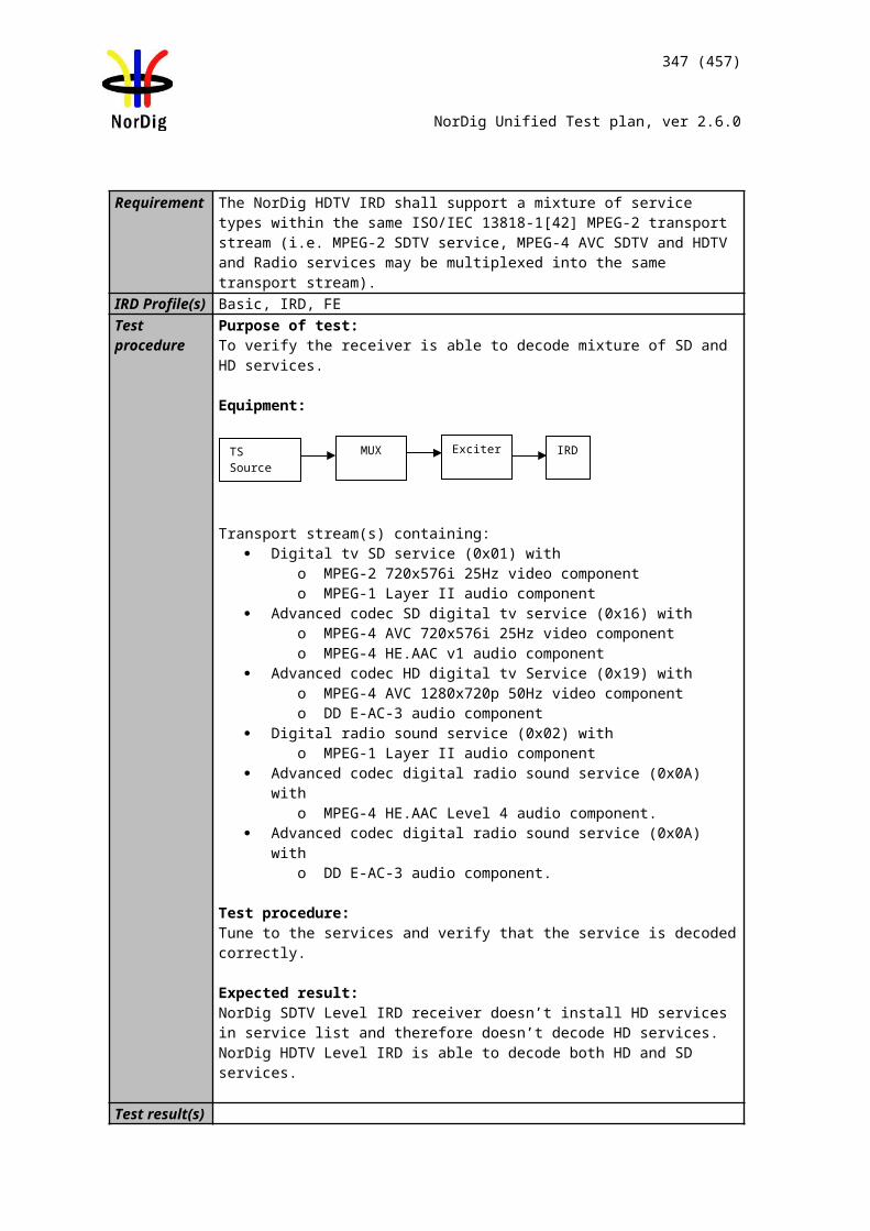
347 (457)
NorDig Unified Test plan, ver 2.6.0
for a notification signal (using DVB SSU’s Update_type 0x4) indicating the availability of new system software and, whenever new software is available, prompt the user with the IRD manufacturer's message associated with that
The NorDig IRD shall support the SSU notifications update type 0x4 using UNT in accordance with the DVB-SSU specification. Linkage descriptor in the NIT table, for linking to the SSU service is defined in section 12.2.6 . The descriptors of the SSU UNT shall be as specified in Section 12.7 .
IRD Profile(s) All IRDs that are using DVB SSU Notfication profileTest procedure Purpose of test:
To verify the IRD system software update process in broadcast channel using DVB SSU Notifications.A typical use case for SSU Notification is to reach all non-connected connectable IRDs via broadcast channel with information that new SSU software is available but the new SSU software size is too large to be distributed via broadcast channel and/or requires a higher bandwidth over broadcast channel than is available.Manufacturers are recommended to:- Pre-store SSU messages in their IRDs and messages should be in all available languages that the IRD supports, - Mainly using the message_index (in the enhanced_message_descriptor, see 12.7.10) to reference which pre-stored message to be displayed for the user, - Minimize the broadcast text (in the enhanced_message_descriptor and/or message descriptor, see 12.7.10).
Equipment:Test setup described in 2.11.2 Error: Reference source not found
Software/configuration information to enable the SSU Notification process in the IRD.
Test procedure: 1. Configure three outgoing download streams from the system software source.
The system software PID, PMT PID and SID may not conflict with each other.2. Configure the multiplexer to transmit three outgoing system software download
streams within TS on the frequency f1. The system software PID, PMT PID and SID may not conflict with each other. (Simulates three system software streams.)
3. Configure linkage_descriptor for the two system software download streams not to be suitable for the IRD under test. The linkage_descriptor parameters for the third download stream shall be suitable for the IRD under test. The third system software download stream shall be the last in order.
4. For the frequency f2 configure linkage_descriptor to refer to the frequency f1 with suitable parameters for the over-the-air download. (Simulates frequency change).
5. Tune the IRD to a service on the frequency f1.6. Perform a manual software update search.7. Verify that a notification is presented 8. Reset the IRD to its factory default settings.9. Repeat step 1-5.10. Perform an automatic search from standby.11. Turn on the IRD from standby.12. Verify that a notification is presented13. Reset the IRD to its factory default settings. 14. Tune the IRD to a service on the frequency f2.
348 (457)
NorDig Unified Test plan, ver 2.6.0
15. Perform a manual software update search.16. Verify that a notification is presented 17. Reset the IRD to its factory default settings.18. Repeat step 1-5.19. Perform an automatic search from standby.20. Turn on the IRD from standby.21. Verify that a notification is presented 22. Fill in the test results.
Expected result: The IRD performs an SSU Notification update..
Test result(s)
Unmatched SSU stream number Unmatched parameter name#1
#2
ONID valueONID value in TS in f1 (country1)
ONID value in TS in f2 (country2)
OK or NOKTest
points6-7
OK or NOKTest
points 10-12
OK or NOKTest
points15-16
OK or NOKTest
points19-21
Verify that any Notification to the user (pop-up message) related to SSU shall be displayed in the same language as the language setting of the IRD.Verify the Notification informs the user about where the new software is available(Internet address) and how to proceed with the update process Verify the user have a choice to postpone/abort/reject the system software update Notification.If the user didn’t choose to abort/ reject the notification verify that the user is reminded with the notification after restart of the IRD
Conformity OK Fault Major Minor, define fail reason in commentsComments If possible describe if fault can be fixed with software update: YES NO
Describe more specific faults and/or other information
Date Sign
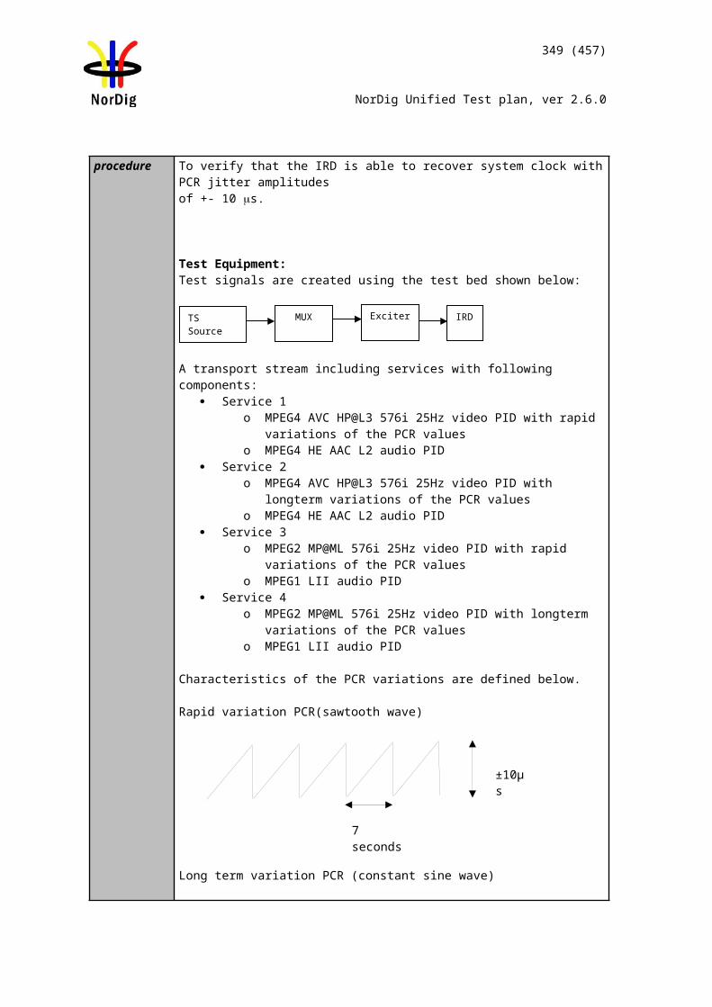
349 (457)
NorDig Unified Test plan, ver 2.6.0
Test Case Task 11:4 IRD System software update using over-the-network download
Section NorDig Unified 10.1, 10.2 and 10.3Requirement The NorDig IRD shall provide a software download mechanism
that enables download of system software, to add a new system software or replace an existing system software.
The upgrade of NorDig IRD software shall be initiated by the user (by update user preference setting and/or by user interaction). The user shall be able to choose the update approach for the IRD (see 10.2.1) and the user shall be able to disable any automatic update. The factory default shall be a value that disables Fully Automatic mode.
In cases where the user is prompted to confirm an update, the user shall be able to confirm or to abort/postpone the update (for example with a Yes and No option). If the user selects to abort/postpone an available update or by other ways cancel an available update, the NorDig IRD shall remind the user as stated in section 10.1.6 in IRD spec.
The NorDig IRD shall be provided with a mechanism ensuring that only newer software versions than the existing System Software are accepted. A connected IRD receiving updates in this way shall still arbitrate between software versions available via the broadcast network and the IP-based broadband network to ensure that only newer versions are downloaded and installed (according with section 10.1.4.2 of IRD spec).
If the NorDig IRD System software is corrupt (due to normal operation of the IRD or due to updating the system software), the IRD manufacturer shall provide a backup mechanism, either on local storage or via download, which can make the IRD operational again.
The NorDig IRD shall be implemented with a protection mechanism for the existing system software. It shall ensure that the existing software will not be corrupted in case the System Software Update (SSU) is interrupted before the new system software is fully downloaded.
IRD Profile(s) All IRDs that are using OTN SSU profileTest procedure Purpose of test:
To verify the IRD system software update process using over-the-network (OTN) download profile.
The SSU end user functionality is not tested in this case. It is tested in Error: Reference source not found6 SSU end user functionality.
Equipment:Test setup described in Error: Reference source not found2 Error: Reference source not found
For the testing three IRD SSU software is needed, “SW v1“,“SW v2“ and “SW v3“, (“SW v1“ as starting point, “SW v2“ for testing upgrading and “SW v3“ for testing ˮnon-downgradingˮ).
IRD manufacturer shall ensure a software upgrade (“SW v2”) is available at the
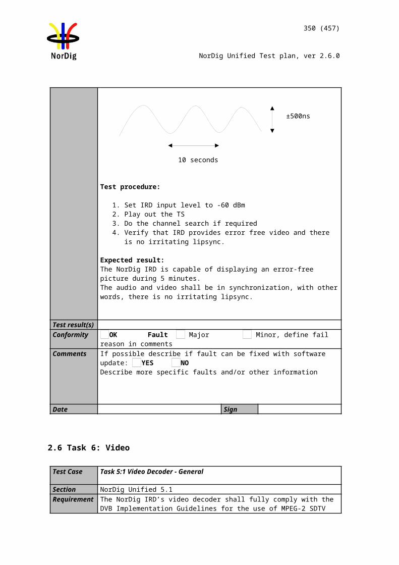
350 (457)
NorDig Unified Test plan, ver 2.6.0
internet.
Internet connection which can be enabled / disabled during the test (e.g. LAN connection through a local switch or Wi-Fi through a local access point)
Two approaches for the SSU testing, either via using:- one single IRD with possibility to upgrade and downgrade the SW by other means plus SSU sw images of “SW v1“ and “SW v3“, - alternative via using multiple IRDs. Two IRDs with software “SW v1“ and one IRD with software “SW v3“.
Test procedure:
1. Connect the IRD to live TV network.2. Connect the IRD to internet. 3. Make sure the IRD has “SW v1” installed.4. Perform factory reset to the IRD and complete the “first time” installation.
During installation, enable/ensure IRD still connected to Internet. 5. Tune the IRD to a TV service (from the live TV network).6. Fill in the test results if the IRD has a setting for automatic search and it is set
to “auto search”.
7. Access the navigator. Look for a menu option for SSU over the Internet.8. Enable SSU download over the Internet.9. Verify that the software in the IRD is updated to “SW v2”.10. Fill in the test protocol.
11. Perform factory reset to the IRD and new installation. During installation, enable network connection on the IRD.
12. Enable SSU download over the Internet.13. Verify that no software update occurs.14. Fill in the test protocol
15. Install/change the IRD software to “SW v3” (OTN server still has SW v2).16. Perform factory reset to the IRD and new installation. During installation,
enable network connection on the IRD.17. Enable SSU download over the Internet.18. Verify that no software update occurs.19. Fill in the test protocol
20. Install/change IRD software to “SW v1” (OTN server still has SW v2).21. Initiate the download again using steps 7-8. 22. During the download (step 8), remove the power cable to corrupt the
downloading of the system software. 23. Wait 10 seconds and then re-insert the power cable. 24. Verify that the IRD is still usable. 25. Fill in the test protocol. Fill in extended information in the comments section if
the IRD ends up in an error state. Error messages etc.
26. Initiate the download again. 27. Cut the network connection temporarily by e.g. disabling the network access
point uplink.28. Re-enable the network connection.29. Fill in the test protocol. Fill in extended information in the comments section if
the IRD ends up in an error state. Error messages etc.
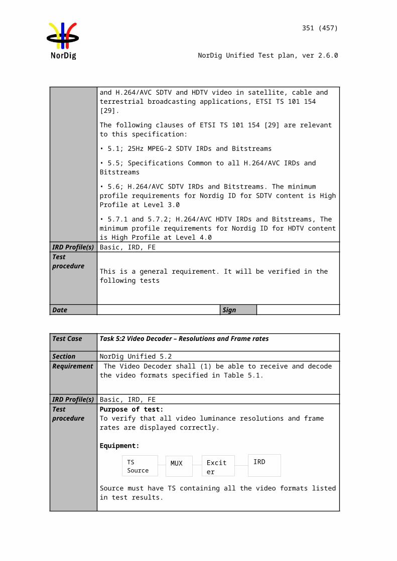
351 (457)
NorDig Unified Test plan, ver 2.6.0
Expected result: IRD performs a software update over-the-network.
Test result(s)
Conformity OK Fault Major Minor, define fail reason in commentsComments If possible describe if fault can be fixed with software update: YES NO
Describe more specific faults and/or other information
Date Sign
Test Case Task 11:5 IRD System software update using USB update
Section NorDig Unified 10.1, 10.2 and 10.3Requirement The NorDig IRD which is relying on OTN updates shall also pro-
vide a USB mechanism that enables the download of software to an IRD.
As many devices will need to be upgraded during their certifica-tion time, that upgrade process should be used as the basis for this test rather than having a dedicated test step where special softwares are required.
The actual upgrade of NorDig IRD software shall be initiated by the user, in this case after inserting a USB device into one of the IRDs USB slot.
Any notification to the user (pop-up message) related to SSU shall be displayed in the same language as the language setting of the IRD.
The IRD manufacturer shall ensure that download of non-certi-fied system-software is prevented.
Test points OK or NOK6 Does IRD have a setting for automatic SSU search
set by default to “auto search” ?7-10 IRD is able to upgrade the System Software over-the-
network.11-14 IRD has a mechansim that ensures only newer
software version than the existing System Software is accepted (testing with same version number)
15-19 IRD has a mechansim that ensures only newer software version than the existing System Software is accepted (testing with lower version number)
20-25 IRD starts after electric break using old (working) software.
26-29 The IRD clarifies the network disturbancies under OTN download. Download is either aborted or resumed after a short network break.
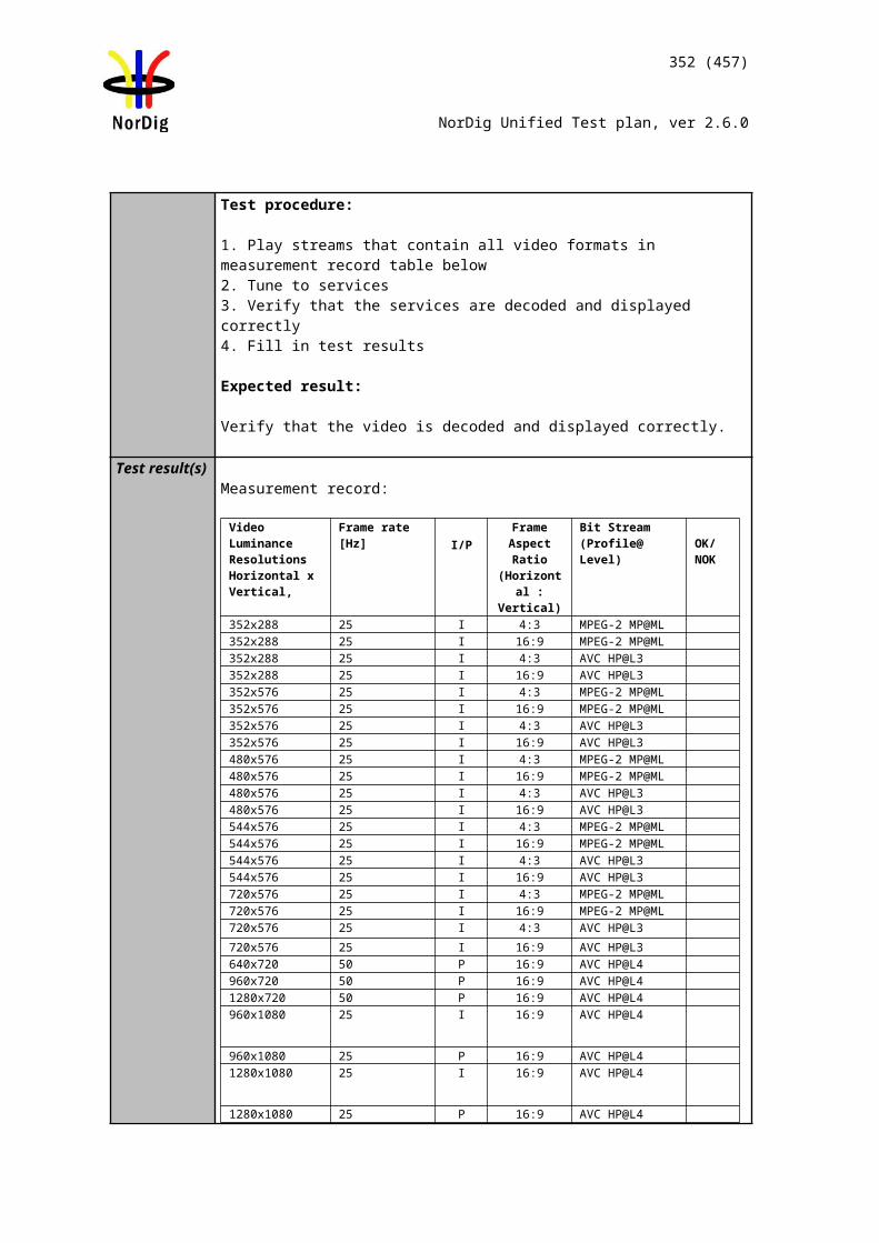
352 (457)
NorDig Unified Test plan, ver 2.6.0
The NorDig IRD shall be implemented with a protection mecha-nism for the existing system software. It shall ensure that the existing software will not be corrupted in case the System Soft-ware Update (SSU) is interrupted before the new system soft-ware is fully installed.
The NorDig IRD shall be provided with a mechanism ensuring that only newer software versions than the existing System Software are accepted.
IRD Profile(s) All IRDs that are using OTN and/or USB SSU profileTest procedure Purpose of test:
To verify the IRD system software update process using the USB interface. The SSU end user functionality is not tested in this case. It is tested in Task 11:6 SSU end user functionality. This test is convenient to do parallel with Task 11:6 SSU end user functionality. Equipment:Test setup described in 2.11.1 Test equipment summary
For testing three IRD software versions are needed:Software “SW v1”, version on USB memory stick, to test IRD does not downgrade. Software “SW v2”, version on USB memory stick, to test upgradeSoftware “SW v3” , version on USB memory stick (special version, only for testlab usage) to allow downgrade SW version during SSU testing.
NOTE: to perform the USB test it is not necessary for the IRD to be connected to either the Broadcast Network or the Internet. Test procedure:
1. Connect the IRD to the live TV network2. Make sure the IRD has “SW v1” installed3. Perform factory reset to the IRD and complete the “first time” installation. 4. Tune the IRD to a TV service (from the live TV network).5. Fill in the test results if the IRD has a setting for automatic search and it is set
to “auto search”
6. Insert the USB device containing the software “SW v2” update (in the format recommended by the manufacturer)
7. The IRD may recognize the USB device and if the IRD offers to perform the SSU at that time accept the offer.
8. Else navigate through the system menu to the Software update screen and select ‘Manual Update’ (or nearest equivalent)
9. Verify that the software is updated to “SWv2” 10. Fill in the test protocol.
11. Perform factory reset to the IRD and complete the “first time” installation. 12. Insert the USB device containing the software “SW v2” update (in the format
recommended by the manufacturer)
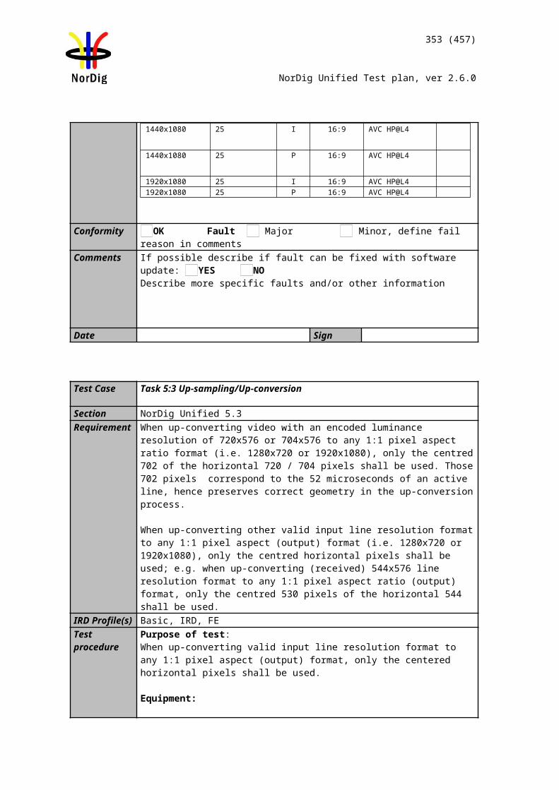
353 (457)
NorDig Unified Test plan, ver 2.6.0
13. The IRD may recognize the USB device and if the IRD offers to perform the SSU at that time accept the offer.
14. Else navigate through the system menu to the Software update screen and select ‘Manual Update’ (or nearest equivalent)
15. Verify that no software update occurs. 16. Fill in the test protocol.
17. Install software “SW v3” version of the IRD software to downgrade the IRD software version using steps 6-8.
18. Verify that the software is updated to a lower version. Note this is a special process to be used only during testing and is not consid-ered a ‘real world’ test.
19. Now using the software “SW v1” again initiate the installation again using steps 6-8.
20. During the update process (step 7 or 8), remove the power cable to corrupt the installation of the system software.
21. Wait 10 seconds and then re-insert the power cable. 22. Verify that the IRD is still usable.23. Fill in the test protocol. Fill in extended information in the comments section if
the IRD ends up in an error state. Error messages etc.
24. Using the software “SW v1”, initiate the installation again using steps 6-8.25. During the update process (step 7 or 8), remove the USB stick to corrupt the in-
stallation of the system software. 26. Verify that the IRD is still usable.27. Fill in the test protocol. Fill in extended information in the comments section if
the IRD ends up in an error state. Error messages etc.
Expected result: IRD performs a software update from the USB source
Test result(s)
Conformity OK Fault Major Minor, define fail reason in commentsComments If possible describe if fault can be fixed with software update: YES NO
Describe more specific faults and/or other information
Date Sign
Test points OK or NOKIRD correctly upgrades its software
IRD starts after power break using old (working) software.
The IRD does not download or install the SSU from other sources/manufacturers
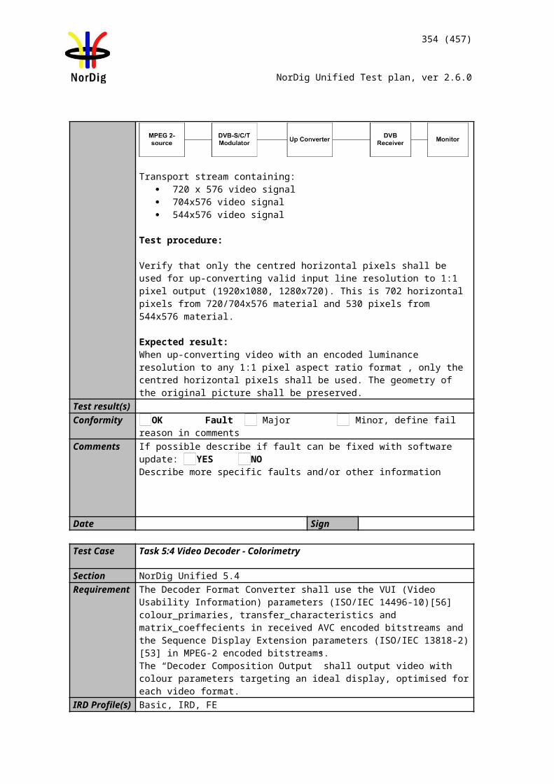
354 (457)
NorDig Unified Test plan, ver 2.6.0
Test Case Task 11:6 SSU end user functionality
Section NorDig Unified 10.1, 10.2, 10.5, 16.4Requirement Any (pop-up) messaging to the user related to SSU shall be displayed in the same lan-
guage as the language setting of the IRD.
If the system software update does not allow the normal utilization of the NorDig IRD, the user shall be warned by some means. For example, by displaying information if the display is not available according to NorDig unified IRD spec section 10.1.3.
If the user selects to abort/postpone an available update or by other ways cancel an available update, the NorDig IRD shall remind the user.
The user shall be able to choose the update approach for the IRD and the user shall be able to disable any automatic update.
If the IRD supports Fully Automatic mode the user must be able to disable Fully Automatic mode
Depending on if the Nordig IRD is connectable or Non connectable the delivery alternatives and the update approaches can vary according to Nordig Unified IRD spec Table 10.1.
IRD Profile(s) Basic, IRD, FETest procedure Purpose of test:
To verify that the IRD has settings required for SSU end user functionality.
This test of common requirements (independent of delivery alternative) is convenient to do parallel with Error: Reference source not found (OTA Simple), 11:2 (OTA enhanced), 11:3 (OTA Notification), 11:4 (OTN) and 11:5 (USB) IRD System software update.
Equipment:Test setup described in 2.11.2 Error: Reference source not found.
Software to upgrade
2 pcs IRDs with older software than the version to upgrade or older software to downgrade the IRD under testing.
Test procedure:
1. Verify that the IRD supports one of the described upgrade delivery altenatives and approach alternatives specified in [1].
2. Fill in the test results.3. Verify that any notification to the user (pop-up message) related to SSU
shall be displayed in the same language as the language setting of the IRD.4. Verify that the user is informed about the upgrade process if the SSU does
not allow the normal utilization of the NorDig IRD.5. Verify the user can cancel the upgrade process6. Verify that if the user selects to abort/postpone an available update or by
other ways cancel an available update, the NorDig IRD shall remind the user.
7. Fill in the test results.
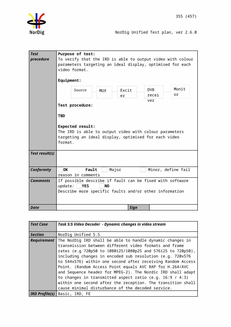
355 (457)
NorDig Unified Test plan, ver 2.6.0
Expected result:
All the test result are OK, and the available upgrade processes works as expected.
Test result(s)Delivery alternatives
Non connectable IRD OK or NOKorN/A
Internet connectable IRD
OKorNOKor N/A
#D1 Mandatory Mandatory to implement at least one of the alternatives #D1, #D2, #D3 or #D4.
#D2 n/a#D3 Optional#D4 n/a
#D5 Optional Optional unless #D1/#D2/#D3 are not implemented, then mandatory.
Approach alternatives
Non connectable IRD OK or NOK or N/A
Internet connectable IRD
OK or NOK or N/A
#A1 Mandatory to implement at least one of the alternatives #A1, #A2 or #A3.
Mandatory to implement at least one of the alternatives #A1, #A2, #A3 or #A4.
#A2#A3
#A4 Optional#A5 Optional Optional
OK or NOK
IRD displays pop-up message with language selected in the settings IRD informs user about upgrade process when applicableUser can cancel the ongoing upgrade processUser can abort/postpone available updateUser is reminded about available updateUser can disable Fully automatic mode.
Conformity OK Fault Major Minor, define fail reason in commentsComments If possible describe if fault can be fixed with software update: YES NO
Describe more specific faults and/or other information
Date Sign
Test Case Task 11:7 Common interface plus (CI+) CAM module system software
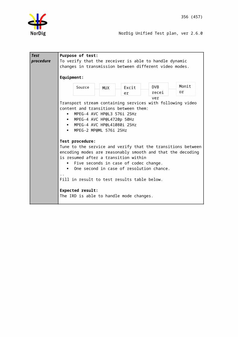
356 (457)
NorDig Unified Test plan, ver 2.6.0
update
Section NorDig Unified 10.6 and Content Security Extensions to the Common Interface. Version 1.4 (CI Plus specifikation)
Requirement In the case of IRDs with CIP- CAM, the IRD shall also support to update the System Software on the CIP-CAM when such software is broadcast.
The IRD shall inform the user whether there is an IRD update or CIP-CAM update.IRD Profile(s) Basic, IDTV, FETest procedure Purpose of test:
To verify the CI+ CAM module can be updated.
Equipment:Test setup described in 2:11:2 Error: Reference source not found
Software to upgrade
Test procedure: 1 Setup equipment for broadcast CI+ CAM update2 Tune the IRD to the multiplex which is carrying the CI+ CAM update3 Verify that CI+ CAM can be updated with CI+ IRD
Expected result: All test results are OK.
Test result(s)Conformity OK Fault Major Minor, define fail reason in commentsComments If possible describe if fault can be fixed with software update: YES NO
Describe more specific faults and/or other information
Date Sign
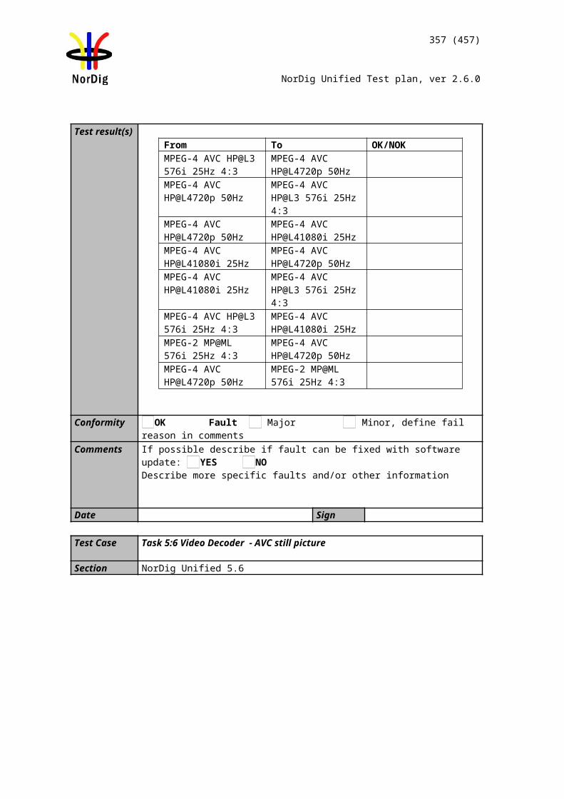
357 (457)
NorDig Unified Test plan, ver 2.6.0
2.12 Task 13: Service Information
2.12.1 GeneralThese test tasks differ from the normal NorDig division of the test tasks. These test tasks are not listed in that order as the requirements appear in NorDig specification. Instead the order of the test tasks are divided in to a order how the different information data shall be able to be retrieved, handled and updated by the receiver. This division in this context is defined as following:
Static PSI/SI data is defined as a data that must be updated by the receiver in the channel search or first time initialization.
Quasi static PSI/SI data is defined as a data that must be updated by the receiver when it is toggled between stand-by mode and active mode or vice versa.
Dynamic PSI/SI data is defined as a data that must be updated by the receiver whenever a change in the data occurs.
In order to maintain the reference to requirements, in every test task, the requirement from the specification is referenced.
Test Case Task 11:1 SI: General
Section NorDig Unified 12.1Requirement The NorDig IRD shall at least start updating for any changes in the received “quasi-
static” SI data after itreturns to active from stand-by mode. “Quasi static“ SI-data includes NIT and SDT, i.e. SI that istypically stored in the flash memory for service navigations, such as service name, service_ID, number ofservices.
The NorDig IRD shall at least start action for any changes in the received “dynamic” PSI and SI data,(PMT, EIT, TDT/TOT, running status and CA mode) within 1 second. (As a guideline for theimplementation, the trigger for changes in received tables can be based on comparing the ‘version id’ inthe tables).
IRD Profile(s) Basic, IRD, FETest procedure
This is general requirement that will be test in following tests.
Test Case Task 11:2 SI: General – Undefined data structures
Section NorDig Unified 12.1Requirement Descriptors or other data structures that are currently undefined or are unknown to
NorDig IRD shall beskipped and shall not cause any harm.IRD Profile(s) Basic, IRD, FETest procedure Purpose of test:
Confirm the proper function
Test procedure:It is a general requirement, which is tested, in the following tests.
Test Case Task 11:3 SI: General – ‘Actual’ and ‘Other’ tables
358 (457)
NorDig Unified Test plan, ver 2.6.0
Section NorDig Unified 12.1Requirement The IRD shall be able to process the PSI/SI tables, both for the ‘Actual’ and for ‘Other’
transport streams. IRD Profile(s) Basic, IRD, FETest procedure
This is a general requirement, which is tested, in the following tests.
Test Case Task 11:4 SI: SI data available through an API
Section NorDig Unified 12.1Requirement The NorDig IRD with an HbbTV-based profile (NorDig Hybrid shall support all the
DVB SI additions as defined in the HbbTV v. 1.5 ETSI TS 102 796 v.1.2.1 specification [30].
IRD Profile(s) Hybrid, IRD, FETest procedure In case of NorDig Basic without API:
Not tested.
In case of NorDig Enhanced:
This test is part of the HbbTV Test Suite. Not tested here
Test Case Task 11:5 SI: Text strings and field size of the SI descriptor
Section NorDig Unified 12.1.7Requirement The NorDig IRD shall support the character tables specified in Table 12.4.
IRD Profile(s) Basic, IRD, FETest procedure Purpose of test:
Check the alphabet tables.
Equipment:
TS containing in SI tables Nordic characters defined in character table ‘Latin Alphabet number 5’.
Test procedure:1. Play-out test sream containing SI tables with text strings that is coded “Latin Alphabet number 5”. Text strings in following SI tables shall be tested:
NIT o network_name
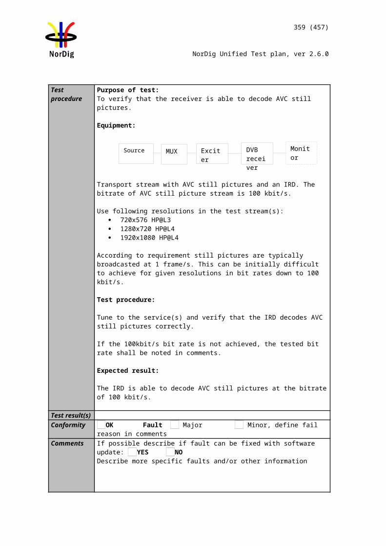
359 (457)
NorDig Unified Test plan, ver 2.6.0
o LCD v2.0 channel_list_name SDT
o Service_name EIT
o Short_evento Extended_event
2.Verify that text strings are displayed as coded in “Latin Alphabet number 5”
Expected result:All text strings are displayed as defined.
Test result(s)Conformity OK Fault Major Minor, define fail reason in commentsComments If possible describe if fault can be fixed with software update: YES NO
Describe more specific faults and/or other information
Date Sign
2.12.2 Static PSI/SI dataTest Case Task 11:6 NIT_actual – frequency_list_descriptor
Section NorDig Unified 12.2.7Requirement NIT descriptors mandatory to receive and interpret if broadcasted:
Network_name_descriptorService_list_descriptorTerrestrial_delivery_system_descriptorLinkage_descriptorPrivate_data_specifier_descriptorFrequency_list_descriptorNordig Logic_channel_descriptor
IRD Profile(s) Basic, IRD, DVB-T, DVB-T2Test procedure Purpose of test:
To check that when there is not correct center_frequency signalled in terrestrial_system_delivery_desc, but the alternative frequencies are available in Frequency_list_desc.
Note: This test is only for terrestrial IRDs.
Equipment:
360 (457)
NorDig Unified Test plan, ver 2.6.0
Service1 Service2MUX1TS_id 1Network_id 1ON_id 1)
SID 1100S_name Test11S_type 0x01PMT PID 1100V PID 1109A PID 1108LCN 1 visible
SID 1200S_name Test12S_type 0x01PMT PID 1200V PID 1209A PID 1208LCN 2 visible
NIT: 3)
terrestrial_system_delivery_descriptor centre_frequency f1 MHz
frequency_list_descriptor centre_frequency f3 MHz
MUX2TS_id 2Network_id 2ON_id 1)
SID 2100S_name Test21S_type 0x01PMT PID 2100V PID 2109A PID 2108LCN 3 visible
SID 2200S_name Test22S_type 0x01PMT PID 2200V PID 2209A PID 2208LCN 4 visible
1) ON_id (Original_network_id) can be chosen in range 0x0001-0xfe00 (operational network) and it shall be same for both muxes.
3) Frequencies f1, f2 and f3 shall be different.
Test procedure:1. Transmit MUX1 at frequency f1 and MUX2 at frequency f2.2. Perform factory reset and new channel search.3. Verify that services on MUX1 can be received correctly.4. Zap to a service on MUX2.5. Change the MUX1 frequency to f3.6. Verify that the IRD is able to utilize the information given in the NIT fre-
quency_list_descriptor and receive the services on MUX1.7. Transmit MUX1 at frequency f2 and MUX2 at frequency f1.8. Perform factory reset and new channel search.9. Verify that services on MUX1 and MUX2 can be received correctly.
Expected result:Terrestrial IRD is able to follow the frequency_list_descriptor and tune to the services, if there is an incorrect frequency in the terrestrial_system_delivery_descriptor.Incorrect centre frequency in frequency_list_descriptor does not cause any harm for the reception.
Test result(s)Conformity OK Fault Major Minor, define fail reason in comments
MUX 1
MUX 2
Exciter 1
Exciter 2Combiner DVB
receiver
TS Source 2
TS Source 1
SI management system
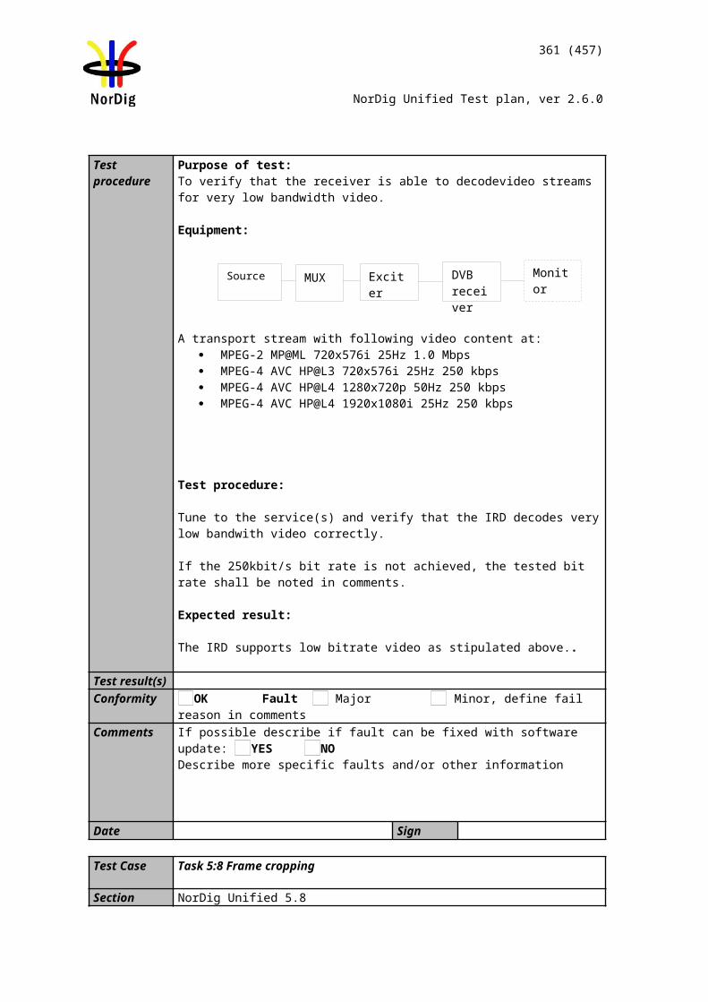
361 (457)
NorDig Unified Test plan, ver 2.6.0
Comments If possible describe if fault can be fixed with software update: YES NODescribe more specific faults and/or other information
Date Sign
Test Case Task 11:7 NIT_actual – Missing terrestrial_system_delivery_descriptor
Section NorDig Unified 12.2.4;Requirement NIT descriptors mandatory to receive and interpret if broadcasted:
Network_name_descriptorService_list_descriptorTerrestrial_delivery_system_descriptorLinkage_descriptorPrivate_data_specifier_descriptorFrequency_list_descriptorNordig Logic_channel_descriptor
IRD Profile(s) Basic, IRD, DVB-T, DVB-T2Test procedure Purpose of test:
To verify the functionality of the receiver when there is no terrestrial_system_delivery_desc signaled.
Note: This test is only for terrestrial IRDs.
Equipment:
Service1 Service2 FrequencyMUX1TS_id 1Network_id 1ON_id 1)
SID 1100S_name Test11S_type 0x01PMT PID 1100V PID 1109A PID 1108LCN 1 visible
SID 1200S_name Test12S_type 0x01PMT PID 1200V PID 1209A PID 1208LCN 2 visible
NIT:Missing terrestrial_system_delivery_descriptor
666 MHz
MUX2TS_id 2Network_id 2ON_id 1)
SID 2100S_name Test21S_type 0x01PMT PID 2100V PID 2109A PID 2108LCN 3 visible
SID 2200S_name Test22S_type 0x01PMT PID 2200V PID 2209A PID 2208LCN 4 visible
730 MHz
MUX 1
MUX 2
Exciter 1
Exciter 2Combiner DVB
receiver
TS Source 2
TS Source 1
SI management system
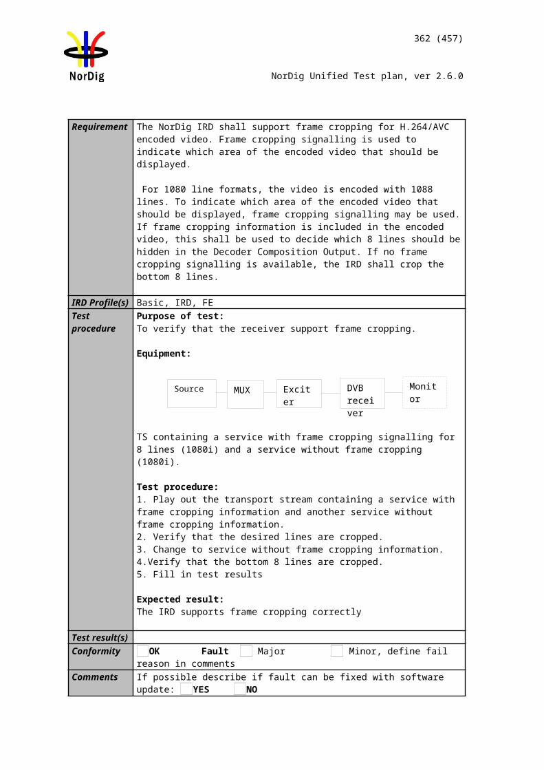
362 (457)
NorDig Unified Test plan, ver 2.6.0
1) ON_id (Original_network_id) can be chosen in range 0x0001-0xfe00 (operational network) and it shall be same for both muxes2)Network_id for DVB-C and DVB-S/S2 IRD tests shall be same in all muxes
Test procedure:1. Remove the terrestrial_system_delivery_descriptor in MUX1 2. Do channel search. 3. Zap between a service on MUX1 and MUX2.4. Confirm that the reception of services in MUX1 and MUX2 is possible.
Expected result:The services are able to receive even when terrestrial_delivery_descriptor is missing.
Test result(s)Conformity OK Fault Major Minor, define fail reason in commentsComments If possible describe if fault can be fixed with software update: YES NO
Describe more specific faults and/or other information
Date Sign
Test Case Task 11:8 NIT_actual – Missing T2_delivery_system_descriptor
Section NorDig Unified 12.2.5;Requirement NIT descriptors mandatory to receive and interpret if broadcasted:
Network_name_descriptorService_list_descriptorTerrestrial_delivery_system_descriptorExtension_descriptor Linkage_descriptorPrivate_data_specifier_descriptorFrequency_list_descriptorNordig Logic_channel_descriptor
T2_delivery_system_descriptor
IRD Profile(s) Basic, IRD, DVB-T, DVB-T2Test procedure Purpose of test:
To verify the functionality of the receiver for the missing T2_delivery_system_desc signaled through the extension_descriptor.
Note: This test is only for terrestrial NorDig T2 IRDs.
Equipment:
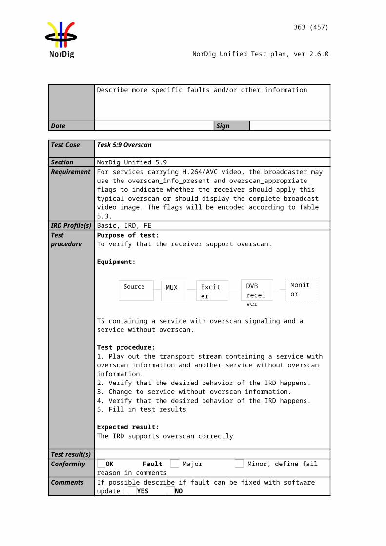
363 (457)
NorDig Unified Test plan, ver 2.6.0
Service1 Service2 FrequencyMUX1TS_id 1Network_id 1ON_id 1)
SID 1100S_name Test11S_type 0x01PMT PID 1100V PID 1109A PID 1108LCN 1 visible
SID 1200S_name Test12S_type 0x01PMT PID 1200V PID 1209A PID 1208LCN 2 visible
NIT:Missing T2_delivery_system_descriptor
666 MHz
MUX2TS_id 2Network_id 2ON_id 1)
SID 2100S_name Test21S_type 0x01PMT PID 2100V PID 2109A PID 2108LCN 3 visible
SID 2200S_name Test22S_type 0x01PMT PID 2200V PID 2209A PID 2208LCN 4 visible
730 MHz
1) ON_id (Original_network_id) can be chosen in range 0x0001-0xfe00 (operational network) and it shall be same for both muxes.2)Network_id for DVB-C and DVB-S/S2 IRD tests shall be same in all muxes
Test procedure:1. Remove the T2_delivery_system_descriptor in MUX1 2. Do channel search. 3. Zap between a service on MUX1 and MUX2.4. Confirm that the reception of services in MUX1 and MUX2 is possible.
Expected result:The services are able to receive even when T2_delivery_system_descriptor is missing.
Test result(s)Conformity OK Fault Major Minor, define fail reason in commentsComments If possible describe if fault can be fixed with software update: YES NO
Describe more specific faults and/or other information
Date Sign
Test Case Task 11:9 SDT_actual service_descriptor and CA_identifier_descriptor
Section NorDig Unified 12.2.6, 12.3.2 and 12.33Requirement SDT descriptors mandatory to receive and interpret if broadcasted:
MUX 1
MUX 2
Exciter 1
Exciter 2Combiner receiver
TS Source 2
TS Source 1
SI management system
364 (457)
NorDig Unified Test plan, ver 2.6.0
Service_descriptorCA_identifier_descriptorLinkage_descriptor
IRD Profile(s) Basic, IRD, FETest procedure Purpose of test:
To check the support for the Service descriptor and CA identifier descriptor.
Equipment:
1) ON_id (Original_network_id) can be chosen in range 0x0001-0xfe00 (operational network)
CA_identifier_descriptor may be present in the SDT when at least one service component is scrambled. The CA_system_id is allocated by ETSI and is given by ETR 162. The descriptor may be used statically (recommended). It will in that case be set according to the services regular/normal scrambling status. Alternatively it may be used dynamically, in accordance with the current services scrambling status. This static use enables IRDs to “grey mark” services that cannot be descrambled due to lack of the required CA-system for the relevant service(s). It allows the IRD to display services that are only temporary (event based) scrambled.
Test procedure:
1. Verify that CA_identifier_descriptor is signaled in SDT_actual for another CA_system_id than supported by the receiver. If the receiver doesn’t support any CA system, the used CA system in EIT_actual p/f can have any valid CA_system_id.
2. Do the first time initialization or a channel search3. Verify that the service1 is displayed as non-available, e.g. “grey marked”.
Expected result:The service1 is displayed as non-available by the receiver.
Test result(s)Conformity OK Fault Major Minor, define fail reason in commentsComments If possible describe if fault can be fixed with software update: YES NO
Describe more specific faults and/or other information
Date Sign
Service1 Service2 Service3 FrequencyMUX TS_id 1Network_id 1ON_id 1)
SID 1100Service type 0x01S_name Test11PMT PID 1100V PID 1109A PID 1108Logical_chan_desc 1 visibleEncrypted
SID 1200Service type 0x02S_name Test12PMT PID 1200V PID 1209A PID 1208Logical_chan_desc 2 visibleClear
SID 1300Service type 0x0CS_name Test13PMT PID 1300V PID 1309A PID 1308Logical_chan_desc 3 visibleClear
Can be chosen depending of the distribution media
365 (457)
NorDig Unified Test plan, ver 2.6.0
2.12.3 Quasi static PSI/SI data
Test Case Task 11:10 Quasi static update of SDT_actual
Section NorDig Unified 12.1.1Requirement The IRD shall at least start updating for any changes in the received “quasi-static” SI
data, (NIT and SDT i.e. SI that is normally stored in the flash memory for service navigations such as service_name, service_ID, number of services), after it return to active from stand-by mode.
IRD Profile(s) Basic, IRD, FETest procedure Purpose of test:
To verify the quasi-static use of the SDT_actual information.
Equipment:
Test procedure:
1. Change the information in SDT; a. service_nameb. service_ID
2. Check that the changes are triggered by toggling the receiver from active mode to stand-by mode and vice versa
Additionally changed tables / descriptors write down in comments which information is changed.
Expected result:Changes are triggered and made..
Test result(s) Update is made: From active mode to stand-by mode From stand-by mode to active mode
In stand-by mode
Conformity OK Fault Major Minor, define fail reason in commentsComments If possible describe if fault can be fixed with software update: YES NO
Describe more specific faults and/or other information
Date Sign
Test Case Task 11:11 Quasi-static update of SDT_actual – linkage to NorDig simulcast replacement service
Section NorDig Unified 12.3.4Requirement 0x82, NorDig Simulcast replacement service, linkage from an (MPEG2 ) SDTV based
service to an (MPEG4 AVC) HDTV replacement service with the same content. It may be used during simulcasting of a service in both an SDTV and an HDTV version on sep-
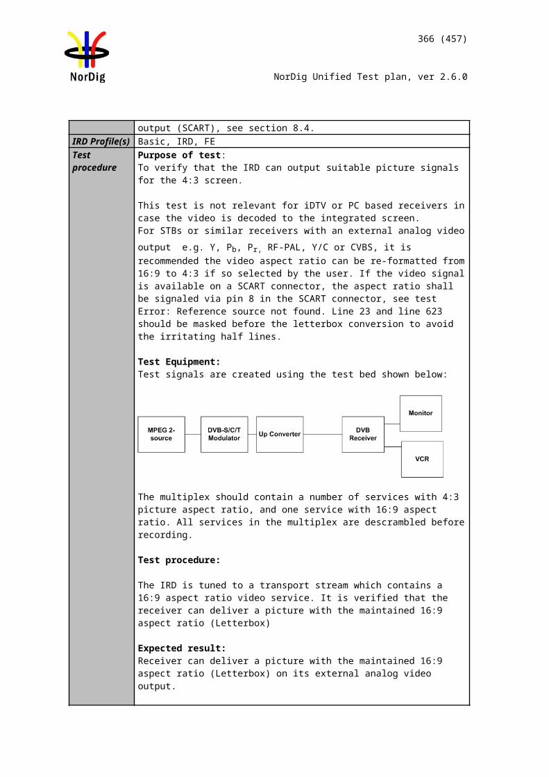
366 (457)
NorDig Unified Test plan, ver 2.6.0
arate service ids with same content within the same original network id. This linkage may be included in the (MPEG2) SDTV service (service_type 0x01) within the SDT pointing to the HDTV version (service_type 0x19) of the service. Whenever it is used, it will be used quasi-static.
When an SDTV service includes this NorDig simulcast replacement service linkage (0x82) pointing to the HDTV version of the service, the NorDig HD IRDs that are able to receive both the SDTV and the HDTV services shall only include the HDTV version/(service) of the two services within its TV service list.
(Clarification: If no ‘NorDig Simulcast replacement service’ linkage is included, both services shall be included. If only the (MPEG-2) SDTV version (service_type 0x01) is possible to receive (due to e.g. reception problems/limitations), the (HDTV) IRD shall include this service even if it carries a linkage ‘NorDig simulcast replacement service’).
IRD Profile(s) Basic, IRD, FETest procedure Purpose of test:
To verify the support for the linkage to simulcast replacement service in SDT_actual.
Equipment:
Service1 Service2 FrequencyMUX1TS_id 1Network_id 1ON_id 1)
SID 1100S_name Test11S_type 0x01PMT PID 1100V PID 1109A PID 1108LCN Ver.1: 1 visibleLCN Ver.2: 1 visible
SID 1200S_name Test12S_type 0x19PMT PID 1200V PID 1209A PID 1208LCN Ver.1: 2 visibleLCN Ver.2: 2 visible
Can be chosen depending of the distribution media
MUX2TS_id 2Network_id 2ON_id 1)
SID 2100S_name Test21S_type 0x01PMT PID 2100V PID 2109A PID 2108LCN Ver.1: 3 visibleLCN Ver.2: 3 visible
SDT_actuallinkage_desc: NorDig Simulcast replacement service pointing to service2 on MUX1
SID 2200S_name Test22S_type 0x01PMT PID 2200V PID 2209A PID 2208LCN Ver.1: 4 visibleLCN Ver.2: 4 visible
Can be chosen depending of the distribution media, but cannot be same as in MUX1
1) ON_id (Original_network_id) can be chosen in range 0x0001-0xfe00 (operational network) and it shall be same for both muxes.2)Network_id for DVB-C and DVB-S/S2 IRD tests shall be same in all muxes
MUX 1
MUX 2
Exciter 1
Exciter 2Combiner DVB
receiver
TS Source 2
TS Source 1
SI management system
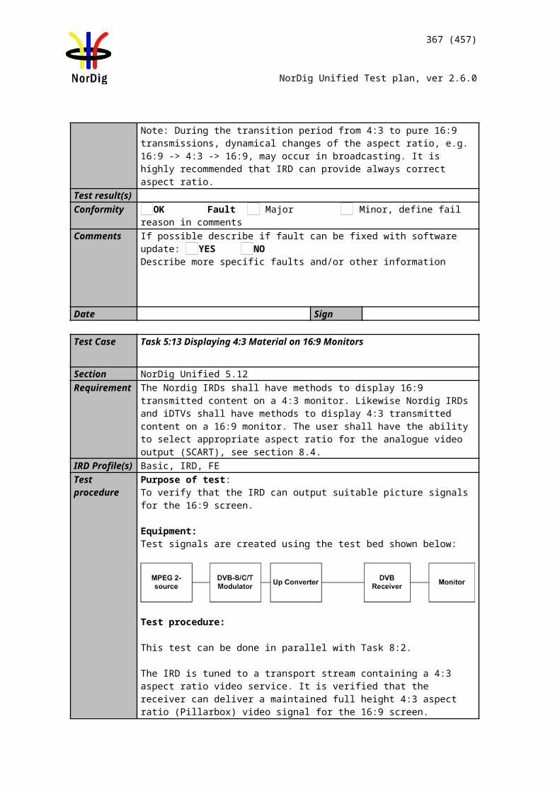
367 (457)
NorDig Unified Test plan, ver 2.6.0
Note 1: NorDig Simulcast replacement service has value 0x82 in linkage_descriptor.
Note 2: Service2 in MUX2 is only for convenience that the HDTV receiver stores service2 MUX2 in the service list.
Test procedure:
1. Verify that the SDT_actuallinkage_descriptor to a simulcast replacement service1 in MUX2 points to service2 in MUX1.
2. Verify following services are able to be received and decoded: Test11, Test12 and Test22
3. Remove SDT_actual linkage_descriptor 0x82 from SDT_actual in MUX24. Toggle receiver to standby and power on it5. Verify following services are able to be received and decoded:
Test11, Test12, Test21 and Test22 6. Add SDT_actual linkage_descriptor 0x82 to SDT_actual in MUX27. Toggle receiver to standby and power on it8. Verify following services are able to be received and decoded:
Test11, Test12 and Test22
Expected result:
Verify that receiver stores only HDTV service (service2 in MUX1) instead of simulcast SDTV service (service1 in MUX2) when linkage_descriptor is signaled.
Verify that receiver is able to receive and decode both HDTV service (service2 in MUX1) and simulcast SDTV service (service1 in MUX2) when linkage_descriptor is not signaled after updating service information quasi-statically.
Verify that receiver stores only HDTV service (service2 in MUX1) instead of simulcast SDTV service (service1 in MUX2) when linkage_descriptor is signaled after updating service information quasi-statically.
Test result(s) Update is made: From active mode to stand-by mode From stand-by mode to active mode
In stand-by mode
Conformity OK Fault Major Minor, define fail reason in commentsComments If possible describe if fault can be fixed with software update: YES NO
Describe more specific faults and/or other information
Date Sign
Test Case Task 11:12 Quasi-static update of NIT_actual – Linkage to an information service about the network
Section NorDig Unified 12.2.6
368 (457)
NorDig Unified Test plan, ver 2.6.0
Requirement NIT Linkage descriptors mandatory to receive and interpret if broadcasted:
0x01 Linkage to an information service about the network0x02 Linkage to EPG service0x04 Linkage to transport stream that carries EIT Schedule information for all services0x09 Linkage to DVB/ETSI System Software Download Service
IRD Profile(s) Basic, IRD, FETest procedure Purpose of test:
To check the support for the Linkage to an information service about the network descriptor.
Test procedure:
From the receiver point of view the linkage to an information service about the network, is practically read dynamically when the user request that information. However, the information of the the linkage to an information service about the network content can be updated when toggling between active mode and standby mode for faster access. The NorDig specification defines the NIT_actual as quasi-static data and therefore this test is classified as quasi-static.
This requirement is tested only with API.
Test result(s)Conformity OK Fault Major Minor, define fail reason in commentsComments If possible describe if fault can be fixed with software update: YES NO
Describe more specific faults and/or other information
Date Sign
Test Case Task 11:13 Quasi-static update of NIT_actual – Linkage to EPG service
Section NorDig Unified 12.2.6Requirement NIT Linkage descriptors mandatory to receive and interpret if broadcasted:
0x01 Linkage to an information service about the network0x02 Linkage to EPG service0x04 Linkage to transport stream that carries EIT Schedule information for all services0x09 Linkage to DVB/ETSI System Software Download Service
IRD Profile(s) Basic, IRD, FETest procedure Purpose of test:
To check the support for the Linkage to EPG service descriptor. To test the use of the linkage_descriptor 0x02 founded in NIT.
Equipment:
369 (457)
NorDig Unified Test plan, ver 2.6.0
Service1 Service2 FrequencyMUX1TS_id 1Network_id 1ON_id 1)
SID 1100S_name Test11PMT PID 1100V PID 1109A PID 1108Logical_chan_desc 1 visible
SID 1200S_name Test12PMT PID 1200V PID 1209A PID 1208Logical_chan_desc 2 visible
NIT: Linkage to EPG service at SID 2200
Can be chosen depending of the distribution media.
MUX2TS_id 2Network_id 2ON_id 1)
SID 2100S_name Test21PMT PID 2100V PID 2109A PID 2108Logical_chan_desc 3 visible
SID 2200S_name Test22PMT PID 2200V PID 2209A PID 2208Logical_chan_desc 0 not visible
NIT: Linkage to EPG service at SID 2200
Can be chosen depending of the distribution media. Not same as for Exciter 1
1) ON_id (Original_network_id) can be chosen in range 0x0001-0xfe00 (operational network) and it shall be same for both muxes2)Network_id for DVB-C and DVB-S/S2 IRD tests shall be same in all muxes
Test procedure:
From the receiver point of view, the linkage to EPG service, is practically read dynamically when the user request the EPG. However, the information of the linkage to EPG content can be updated when toggling between active mode and standby mode for faster access. The NorDig specification defines the NIT_actual as quasi-static data and therefore this test is classified as quasi-static.
1. Check that there is an EPG service available in the stream at SID 2200. 2. Press the guide button and check that EPG is started. 3. Change a parameter in the linkage to EPG content4. Toggle between active mode and standby mode. 5. If it is relevant, note if the data content in the linkage is updated.
Expected result:The EPG is started. (Not relevant for NorDig Basic)
Test result(s)Conformity OK Fault Major Minor, define fail reason in commentsComments If possible describe if fault can be fixed with software update: YES NO
Describe more specific faults and/or other information
Date Sign
MUX 1
MUX 2
Exciter 1
Exciter 2Combiner STB
TS Source 2
TS Source 1
SI management system
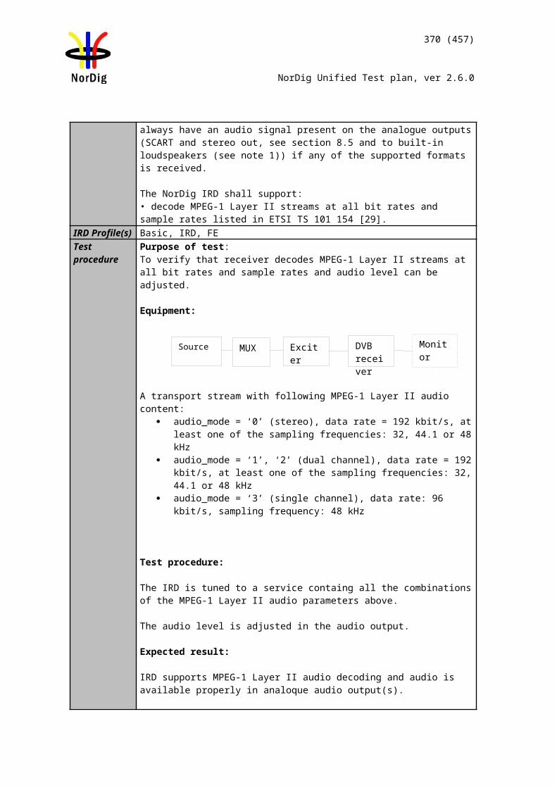
370 (457)
NorDig Unified Test plan, ver 2.6.0
Test Case Task 11:14 Quasi-static update of NIT_actual – Linkage to TS that carriers EIT sch information for all services
Section NorDig Unified 12.2.6Requirement Linkage_type 0x04 (“Transport stream containing complete network/bouquet SI”) is
used for this purpose.IRD Profile(s) Basic, IRD, FETest procedure
From the receiver point of view, the linkage to TS that carriers EIT sch information for all services, is practically read dynamically when the user request that information. However, the information of the the linkage to TS that carriers EIT sch information for all services content can be updated when toggling between active mode and standby mode for faster access. The NorDig specification defines the NIT_actual as quasi-static data and therefore this test is classified as quasi-static.
This requirement is tested inTask 11:22.
Test Case Task 11:15 Quasi-static update of NIT_actual – Linkage to System Software Download service
Section NorDig Unified 12.2.6Requirement NIT Linkage descriptors mandatory to receive and interpret if broadcasted:
0x09 Linkage to DVB/ETSI System Software Download Service
IRD Profile(s) Basic, IRD, FETest procedure Purpose of test:
To check the support for the Linkage to DVB/ETSI System Software Download Service
Test procedure:
This requirement is tested in Test Task 11.
2.12.4 Dynamic PSI/SI data
Test Case Task 11:16 Dynamic update of SDT_actual running status and linkage to a service replacement service
Section NorDig Unified 12.1 and 12.3.4Requirement SDT descriptors mandatory to receive and interpret if broadcasted:
Linkage_descriptor
0x05, linkage to a service replacement service. When present, the receiver shall automatically switch to the replacement service if the ‘running_status’ is set to “1” (not running) and if the receiver are able to receive the SDT containing the original service during the replacement, also switch back when ‘running_status” is set to “4” (running).
IRD Profile(s) Basic, IRD, FETest procedure Purpose of test:
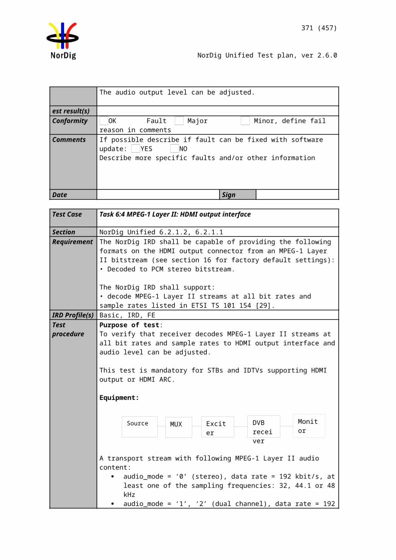
371 (457)
NorDig Unified Test plan, ver 2.6.0
To check the support for the Linkage to service replacement service in SDT.
Equipment:
Service1 Service2 FrequencyMUX1TS_id 1Network_id 1ON_id 1)
SID 1100S_name Test11S_type 0x01PMT PID 1100V PID 1109A PID 1108LCN 1 visible
SID 1200S_name Test12S_type 0x01PMT PID 1200V PID 1209A PID 1208LCN 2 visible
SDT: linkage_descriptor 0x05 pointing to service1 on MUX2
Can be chosen depending of the distribution media
MUX2TS_id 2Network_id 2ON_id 1)
SID 2100S_name Test21S_type 0x01PMT PID 2100V PID 2109A PID 2108LCN 3 visible
SID 2200S_name Test22S_type 0x01PMT PID 2200V PID 2209A PID 2208LCN 4 visible
Can be chosen depending of the distribution media, but cannot be same as in MUX1
1) ON_id (Original_network_id) can be chosen in range 0x0001-0xfe00 (operational network) and it shall be same for both muxes2)Network_id for DVB-C and DVB-S/S2 IRD tests shall be same in all muxes
Test procedure:
1. Verify that all service have running_status 4 (running)2. Verify that all services are able to be received and decoded3. Choose the service2 on MUX14. Change running_status of service2 on MUX1 to 1 (not running)5. Verify that receiver receives and decodes service1 on MUX2
Expected result:
Verify that receiver receives and decodes service1 on MUX2.
Test result(s)Conformity OK Fault Major Minor, define fail reason in commentsComments If possible describe if fault can be fixed with software update: YES NO
Describe more specific faults and/or other information
MUX 1
MUX 2
Exciter 1
Exciter 2Combiner DVB
receiver
TS Source 2
TS Source 1
SI management system
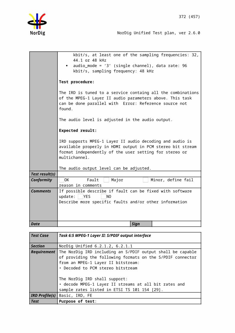
372 (457)
NorDig Unified Test plan, ver 2.6.0
Date Sign
Test Case Task 11:17 Dynamic update of EIT actual/other p/f
Section NorDig Unified 13.3.2Requirement NorDig IRD shall make use of the EIT p/f tables from both EIT_actual and EIT_other
tables.
The NorDig IRD manufacturer shall provide a procedure that allows the user to configure blanking of video and muting of sound for certain parental rating values.
If information is missing (i.e. not included in the transmission) the ESG shall not display an error message, instead the text information field shall stay empty (i.e. no information like “no information available”).
IRD Profile(s) Basic, IRD, FETest procedure Purpose of test:
To check that relevant contents of the EIT actual/other p/f are decoded and displayed correctly.
Equipment:
Service1 Service2 FrequencyMUX1TS_id 1Network_id 1ON_id 1)
SID 1100S_name Test11PMT PID 1100V PID 1109A PID 1108Logical_chan_desc 1 visible
SID 1200S_name Test12PMT PID 1200V PID 1209A PID 1208Logical_chan_desc 2 visible
EIT actual/other p/f
Can be chosen depending of the distribution media.
MUX2TS_id 2Network_id 2ON_id 1)
SID 2100S_name Test21PMT PID 2100V PID 2109A PID 2108Logical_chan_desc 3 visible
SID 2200S_name Test22S_type 0x01PMT PID 2200V PID 2209A PID 2208Logical_chan_desc 4 visible
EIT actual/other p/f
Can be chosen depending of the distribution media. Not same as for Exciter 1
1) ON_id (Original_network_id) can be chosen in range 0x0001-0xfe00 (operational network) and it shall be same for both muxes.2)Network_id for DVB-C and DVB-S/S2 IRD tests shall be same in all muxes
Test procedure:
MUX 1
MUX 2
Exciter 1
Exciter 2Combiner STB
TS Source 2
TS Source 1
SI management system
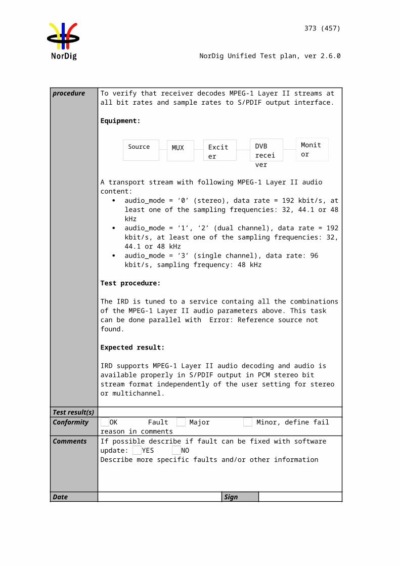
373 (457)
NorDig Unified Test plan, ver 2.6.0
1. Verify that there is one visible service with EIT information signalled on MUX1, one visible service without EIT signalled on MUX1 and one service with EIT signalled on MUX2.
2. Launch navigator.3. Check that service with and without EIT signalled is displayed correctly. 4. Verify that the EIT p/f has prority over EIT schedule in navigator (in case if the
EIT p/f and EIT schedule has a conflict in EIT information)
Expected result:
The IRD shall display the information signalled in EIT from MUX1 and MUX2 correctly in navigator inclusive all the descriptor defined above.
The IRD shall not display error message for the service, which don’t have EIT signalled, on MUX1.
The ESG has equal layout for all services in one service type.
Test result(s)Conformity OK Fault Major Minor, define fail reason in commentsComments If possible describe if fault can be fixed with software update: YES NO
Describe more specific faults and/or other information
Date Sign
Test Case Task 11:18 Dynamic update of EIT_actual p/f CA_identifier_descriptor
Section NorDig Unified 12.4.3Requirement EIT_actual p/f descriptors mandatory to receive and interpret if broadcasted:
CA_identifier_descriptor
This descriptor is optional, however, it may be present in the EIT whenever at least one service component is scrambled. The CA_system_id is allocated by ETSI and is given by ETR 162 [16]. When used, it will be used dynamically, i.e. following the services scrambling status, mainly targeting the ESG/EPG applications.
IRD Profile(s) Basic, IRD, DVB-T, DVB-T2Test procedure Purpose of test:
To verify the support for the dynamic interpretation of the CA_identifier_descriptor in EIT_actual p/f.
This test is optional for satellite and cable IRD.
Equipment:
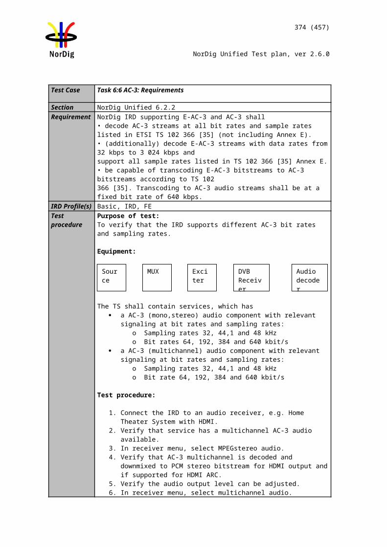
374 (457)
NorDig Unified Test plan, ver 2.6.0
Service1 Service2 FrequencyMUX1TS_id 1Network_id 1ON_id 1)
SID 1100S_name Test11PMT PID 1100V PID 1109A PID 1108Logical_chan_desc 1 visible
SID 1200S_name Test12PMT PID 1200V PID 1209A PID 1208Logical_chan_desc 2 visible
EIT: CA_identifier_descriptor signaled for a CA_system_id
Can be chosen depending of the distribution media
1) ON_id (Original_network_id) can be chosen in range 0x0001-0xfe00 (operational network) and it shall be same for both muxes2)Network_id for DVB-C and DVB-S/S2 IRD tests shall be same in all muxes
Test procedure:
1. Verify that CA_identifier_descriptor is signaled for a service2 next event_id in EIT_actual p/f for a CA_system_id supported by the receiver. If the receiver doesn’t support any CA system, the used CA system in EIT_actual p/f can have any valid CA_system_id.
2. Verify by accessing the ESG or EPG that the event is marked as scrambled.
Expected result:The event is marked as scrambled in the ESG or EPG.
Test result(s)Conformity OK Fault Major Minor, define fail reason in commentsComments If possible describe if fault can be fixed with software update: YES NO
Describe more specific faults and/or other information
Date Sign
Test Case Task 11:19 Dynamic update of EIT actual/other p/f short_event_descriptor, extended_event_descriptor and content_descriptor
Section NorDig Unified 12.4Requirement EIT descriptors mandatory to receive and interpret if broadcasted:
Short_event_descriptorExtended_event_descriptorComponent_descriptorContent_descriptorParental_rating_descriptorPrivate_data_specifier_descriptor
IRD Profile(s) Basic, IRD, FETest procedure Purpose of test:
To check the support for the following descriptors in EIT actual/other p/f: Short_event_descriptorExtended_event_descriptorContent_descriptor
375 (457)
NorDig Unified Test plan, ver 2.6.0
Equipment:
Service1 Service2 FrequencyMUX1TS_id 1Network_id 1ON_id 1)
SID 1100S_name Test11PMT PID 1100V PID 1109A PID 1108Logical_chan_desc 1 visible
SID 1200S_name Test12PMT PID 1200V PID 1209A PID 1208Logical_chan_desc 2 visible
Can be chosen depending of the distribution media.
MUX2TS_id 2Network_id 2ON_id 1)
SID 2100S_name Test21PMT PID 2100V PID 2109A PID 2108Logical_chan_desc 3 visible
SID 2200S_name Test22PMT PID 2200V PID 2209A PID 2208Logical_chan_desc 4 visible
Bouquet SIAll information in EIT.
Can be chosen depending of the distribution media. Not same as for Exciter 1
1) ON_id (Original_network_id) can be chosen in range 0x0001-0xfe00 (operational network) and it shall be same for both muxes2)Network_id for DVB-C and DVB-S/S2 IRD tests shall be same in all muxes
Test procedure:
1. Check that the descriptors above are signalled for the two tables EIT actual and other p/f
2. Choose a service which have descriptors signalled and access the info banner. 3. Check that the information on info banner is correct (EIT actual p/f).4. Keep the same channel, but zap using the info banner to an other service. 5. Check that the information on info banner is correct (EIT other p/f).6. Change the information in content_descriptor to Movie/Drama, News/Current
affairs, Show/Game show, Sports, Children's/Youth programmes, Music/Ballet/Dance, Arts/Culture (without music), Social/Political issues/Economics, Education/ Science/Factual topics and Leisure hobbies, in hexadecimal values 0x1 – 0xA respectively.
7. Check that the changes are updated in info banner.
Expected result:The info banner shows the information signalled in descriptors above and it is changed the information is updated.
Test result(s)Conformity OK Fault Major Minor, define fail reason in comments
MUX 1
MUX 2
Exciter 1
Exciter 2Combiner STB
TS Source 2
TS Source 1
SI management system
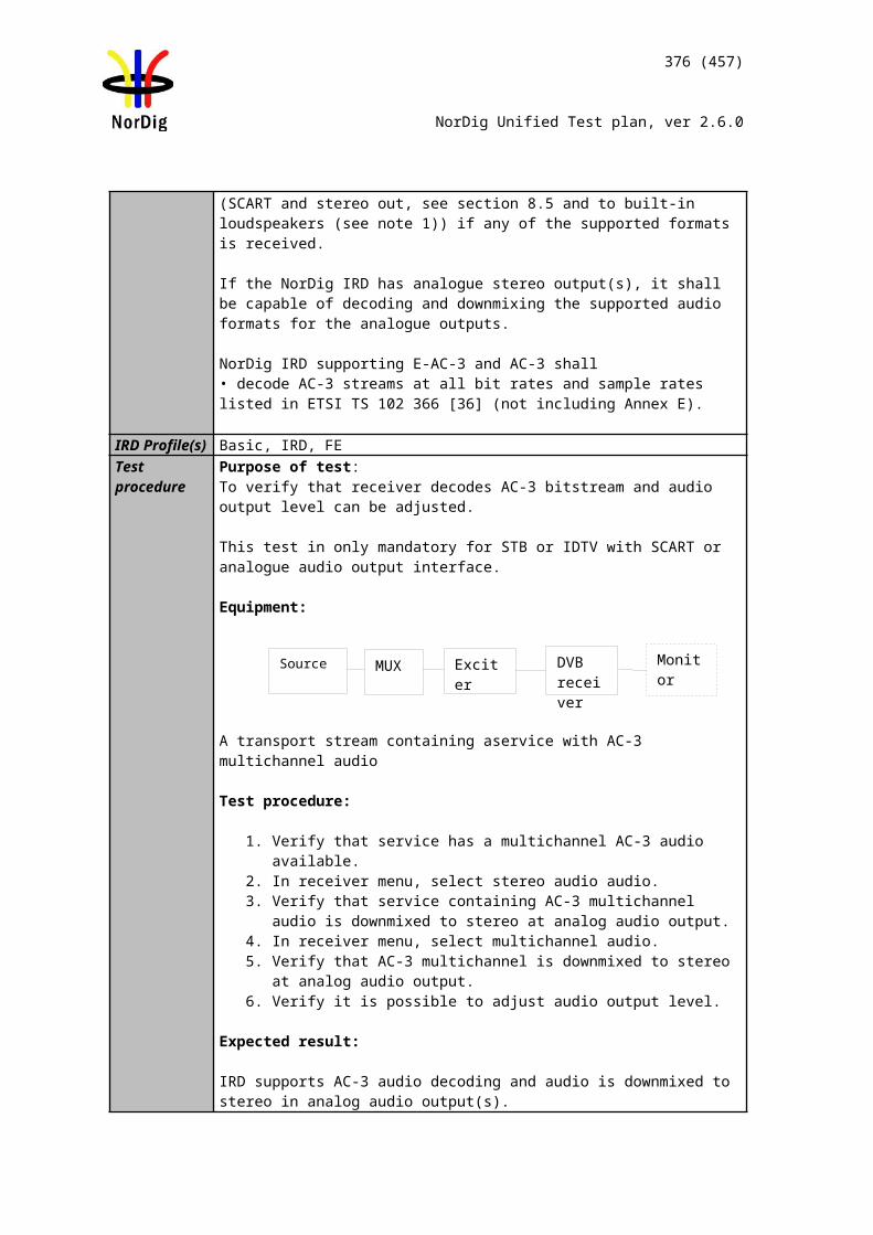
376 (457)
NorDig Unified Test plan, ver 2.6.0
Comments If possible describe if fault can be fixed with software update: YES NODescribe more specific faults and/or other information
Date Sign
Test Case Task 11:20 Dynamic update of EIT actual/other p/f content descriptor and component_descriptor
Section NorDig Unified 12.4Requirement EIT descriptors mandatory to receive and interpret if broadcasted:
Short_event_descriptorExtended_event_descriptorComponent_descriptorContent_descriptorParental_rating_descriptorPrivate_data_specifier_descriptorCA_identifier_descriptor (optional)
IRD Profile(s) Basic, IRD, FETest procedure Purpose of test:
To check the support for the following descriptors in EIT p/f: Content_descriptor (because it is needed in component descriptor)Component_descriptor
This test is a subset of the all combinations of values defined for content_descriptor / component_descriptor. The following combinations are tested:
Stream_content Component_desc Language
0x01 0x01 MPEG2 SD video, 4:3, 25Hz swe/fin/nor/dan/ice/sami
0x01 0x03 MPEG2 SD video, 16:9, 25Hz without pan
vectors
swe/fin/nor/dan/ice/sami
0x02 0x01 MPEG1 LII Audio mono swe/fin/nor/dan/ice/sami
0x02 0x02 MPEG1 LII Audio dual mono swe/fin/nor/dan/ice/sami
0x02 0x03 MPEG1 LII Audio stereo (2 channel) swe/fin/nor/dan/ice/sami
0x05 0x01 MPEG4 AVC SD video, 4:3, 25Hz swe/fin/nor/dan/ice/sami
0x05 0x03 MPEG4 AVC SD video, 16:9, 25Hz swe/fin/nor/dan/ice/sami
0x05 0x0B MPEG4 AVC HD video, 16:9, 25Hz swe/fin/nor/dan/ice/sami
Equipment:
377 (457)
NorDig Unified Test plan, ver 2.6.0
Service1 Service2 FrequencyMUX1TS_id 1Network_id 1ON_id 1)
SID 1100S_name Test11S_type 0x01PMT PID 1100V PID 1109A PID 1108LCN 1 visible
SID 1200S_name Test12S_type 0x01PMT PID 1200V PID 1209A PID 1208LCN 2 visible
Can be chosen depending of the distribution media.
MUX2TS_id 2Network_id 2ON_id 1)
SID 2100S_name Test21S_type 0x19PMT PID 2100V PID 2109A PID 2108LCN 3 visible
SID 2200S_name Test22S_type 0x16PMT PID 2200V PID 2209A PID 2208LCN 4 visible
Bouquet SIAll information in EIT.
Can be chosen depending of the distribution media. Not same as for Exciter 1
1) ON_id (Original_network_id) can be chosen in range 0x0001-0xfe00 (operational network) and it shall be same for both muxes.2)Network_id for DVB-C and DVB-S/S2 IRD tests shall be same in all muxes
Test procedure:
1. Check that these descriptors doesn’t cause any harm for the receiver and the content of the component descriptor is displayed correctly.
Expected result:Content_descriptor and component_descriptor don’t cause any harm if they are not visible. Content_descriptor and component_descriptor are decoded correctly if they are visible in info banner or/and ESG.
Test result(s)Conformity OK Fault Major Minor, define fail reason in commentsComments If possible describe if fault can be fixed with software update: YES NO
Describe more specific faults and/or other information
Date Sign
MUX 1
MUX 2
Exciter 1
Exciter 2Combiner STB
TS Source 2
TS Source 1
SI management system
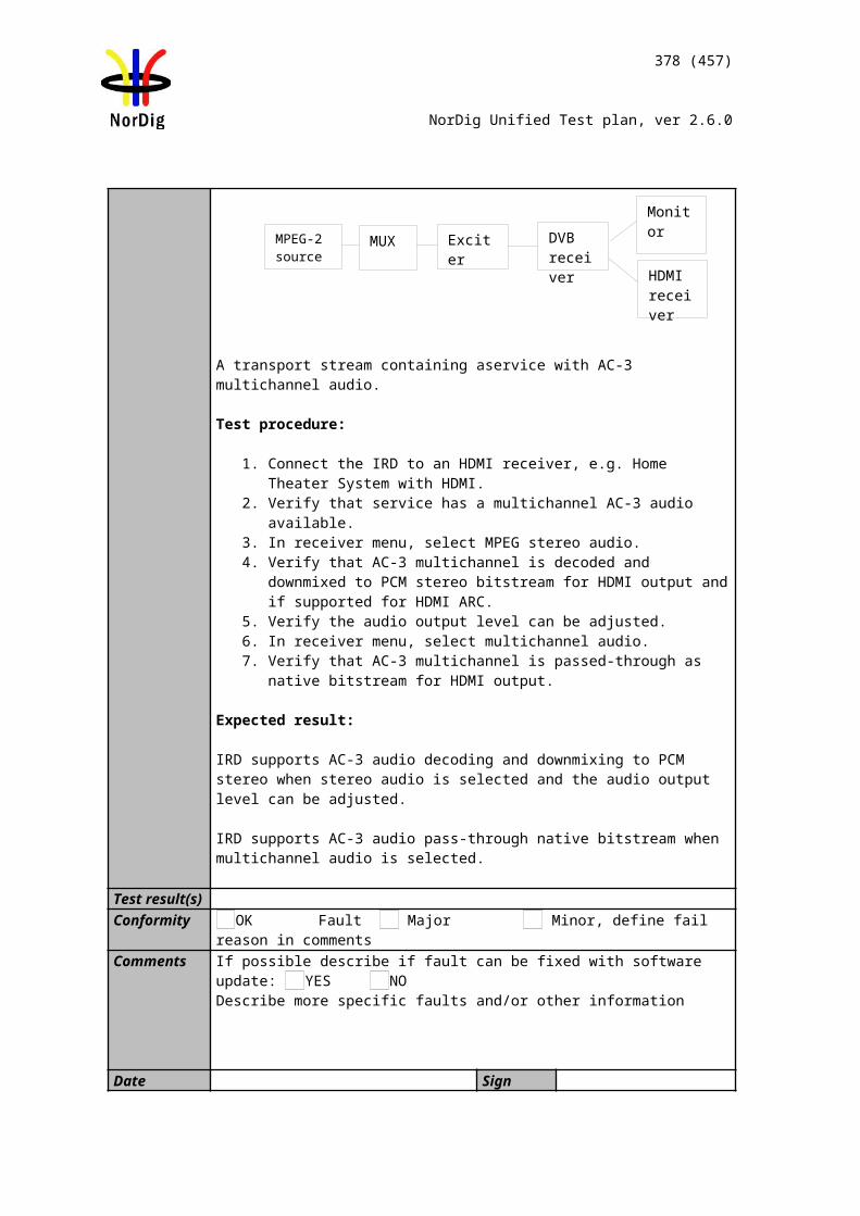
378 (457)
NorDig Unified Test plan, ver 2.6.0
Test Case Task 11:21 Dynamic update of EIT actual/other p/f parental_rating_descriptor
Section NorDig Unified 13.3.2Requirement The IRD manufacturer shall provide a procedure that allows the user to configure
blanking of video and muting of sound for certain parental rating values (in parental_rating_descriptor in the EIT p/f).
IRD Profile(s) Basic, IRD, FETest procedure Purpose of test:
To check that muting of audio and blanking of video works.
Equipment:
Service1 Service2 FrequencyMUX1TS_id 1Network_id 1ON_id 1)
SID 1100S_name Test11S_type 0x01PMT PID 1100V PID 1109A PID 1108LCN 1 visible
SID 1200S_name Test12S_type 0x01PMT PID 1200V PID 1209A PID 1208LCN 2 visible
Can be chosen depending of the distribution media.
MUX2TS_id 2Network_id 2ON_id 1)
SID 2100S_name Test21S_type 0x01PMT PID 2100V PID 2109A PID 2108LCN 3 visible
SID 2200S_name Test22S_type 0x01PMT PID 2200V PID 2209A PID 2208LCN 4 visible
Bouquet SIAll information in EIT.
Can be chosen depending of the distribution media. Not same as for Exciter 1
1) ON_id (Original_network_id) can be chosen in range 0x0001-0xfe00 (operational network) and it shall be same for both muxes2)Network_id for DVB-C and DVB-S/S2 IRD tests shall be same in all muxes
Test procedure:
1. Verify that current program has lower parental_rating than the parental_rating settings allowed in the preferences of the IRD on MUX 1.
2. Zap to channel and verify that video is visible3. Verify that next program in the current a services EIT information is signalled
for higher parental_rating as allowed in preferences of the IRD on MUX14. Watch service and verify that EIT present information is updated to the next
program
MUX 1
MUX 2
Exciter 1
Exciter 2Combiner STB
TS Source 2
TS Source 1
SI management system
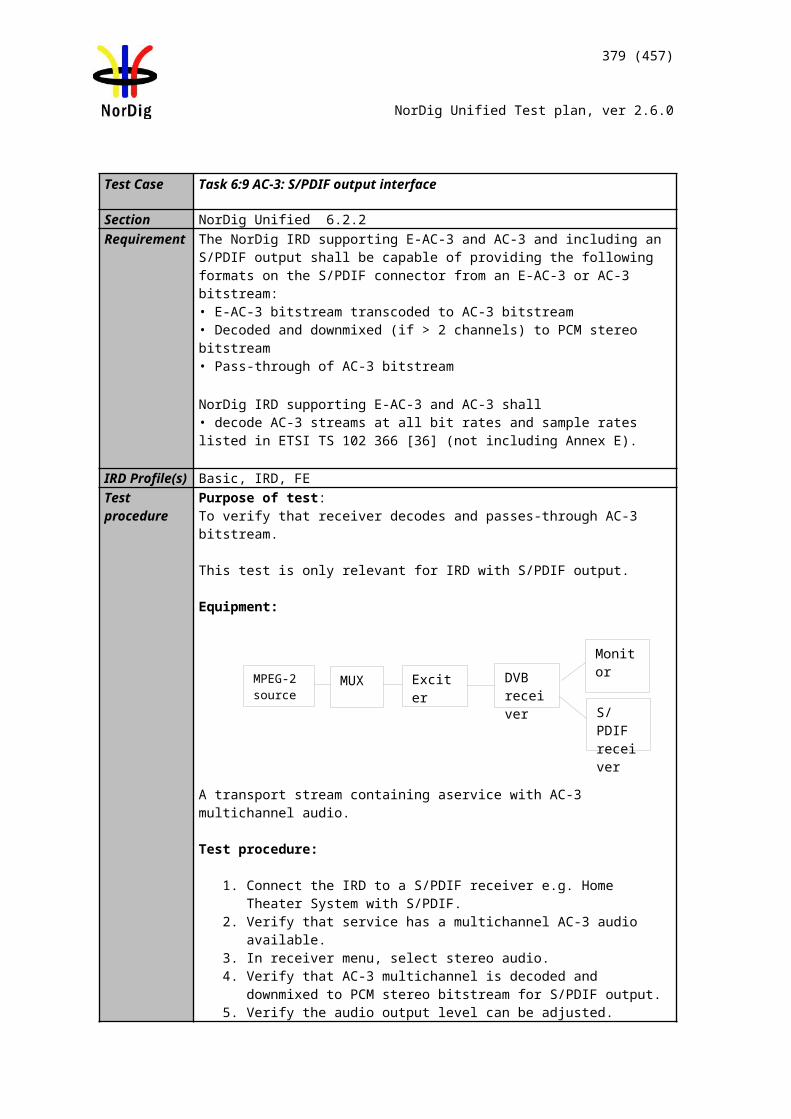
379 (457)
NorDig Unified Test plan, ver 2.6.0
5. Verify that the video is blanked and the audio is muted.6. Watch the service until the EIT event information is changed to next program,
which has the lower parental_rating as allowed in the preferences.7. Verify that the video is visible and audio is audible after EIT_present update.8. Verify that the EIT p/f has prority over EIT schedule in navigator (in case if the
EIT p/f and EIT schedule has a conflict in EIT information)
Expected result:
The IRD shall blank the video and mute the audio for ages that are not allowed to decode.
Test result(s)Conformity OK Fault Major Minor, define fail reason in commentsComments If possible describe if fault can be fixed with software update: YES NO
Describe more specific faults and/or other information
Date Sign
Test Case Task 11:22 Dynamic update of EIT actual/other p/f and schedule in ESG using linkage
Section NorDig Unified 12.4.7, 12.2.6, 13.3.1 and 13.3.2Requirement Upon user request for EIT schedule information, the IRD shall look for the reference us-
ing linkage descriptor mechanism in the NIT and perform a frequency re-tuning if neces-sary. Linkage_type 0x04 (“Transport Stream containing complete network/bouquet SI”) shall be used to refer to EIT schedule information.
The ESG shall include the EIT present/following table.
The NorDig IRD shall be able to handle situations when the EIT is not present.
The ESG shall be non-discriminatory and display all services on equal basis.
The ESG shall process and display the relevant content of the following tables (including start time, end time/duration, and content of all descriptors specified below
If information is missing (i.e. not included in the transmission) the ESG shall not display an error message, instead the text information field shall stay empty (i.e. no information like “no information available”).
Short_event_descExtended_event_descComponent_descContent_descParental_rating_descCA_identifier_descriptor (optional)
IRD Profile(s) Basic, IRD, FETest procedure Purpose of test:
To verify the dynamic update of EIT actual/other schedule information in ESG using the linkage_descriptor 0x04 (“Transport Stream containing complete network/bouquet SI”) in NIT.
380 (457)
NorDig Unified Test plan, ver 2.6.0
The verify the handling of the EIT schedule descriptors in NorDig Basic receiver:Short_event_descriptorComponent_descriptorExtend_event_descriptorParental_rating_descriptor
Equipment:
Service1 Service2 FrequencyMUX1TS_id 1Network_id 1ON_id 1)
SID 1100S_name Test11S_type 0x01PMT PID 1100V PID 1109A PID 1108LCN 1 visible
SID 1200S_name Test12S_type 0x01PMT PID 1200V PID 1209A PID 1208LCN 2 visible
Can be chosen depending of the distribution media.
MUX2TS_id 2Network_id 2ON_id 1)
SID 2100S_name Test21S_type 0x01PMT PID 2100V PID 2109A PID 2108LCN 3 visible
SID 2200S_name Test22S_type 0x01PMT PID 2200V PID 2209A PID 2208LCN 4 visible
Bouquet SIAll information in EIT a/o sch.
Can be chosen depending of the distribution media. Not same as for Exciter 1
1) ON_id (Original_network_id) can be chosen in range 0x0001-0xfe00 (operational network) and it shall be same for both muxes2)Network_id for DVB-C and DVB-S/S2 IRD tests shall be same in all muxes
On MUX1 in NIT_actual first loop configure linkage_type 0x04 to point to MUX2. On MUX2 configure complete transport stream/bouquet SI. In linkage_descriptor the service_id shall be 0x0000.
Test procedure:
1. Turn on receiver. 2. Do re-initialization or make sure there are no services in channel list or in ESG. 3. Do channel search. 4. Check in channel list or ESG that there are services available. 5. Press the Guide button.6. Check that the EIT information is displayed correctly as signalled for 8 days
(current day + 7 full days – 24 hours) in EIT schedule.7. Verify that extended amount (more than 8 days) of EIT data do not cause
problems with the receiver
MUX 1
MUX 2
Exciter 1
Exciter 2Combiner DVB
receiver
TS Source 2
TS Source 1
SI management system
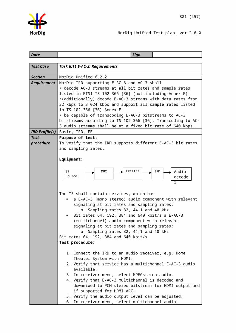
381 (457)
NorDig Unified Test plan, ver 2.6.0
8. Verify that the EIT p/f has prority over EIT schedule in navigator (in case if the EIT p/f and EIT schedule has a conflict in EIT information)
Expected result: Linkage to transport stream/bouquet information is displayed correctly as signalled in EIT schedule for following descriptors:Short_event_descriptorComponent_descriptorExtend_event_descriptorParental_rating_descriptor
Test result(s)NOK OR OK
The services and events can be presented to viewer.EIT information is available for all services and event and it is visible to viewer.
Conformity OK Fault Major Minor, define fail reason in commentsComments If possible describe if fault can be fixed with software update: YES NO
Describe more specific faults and/or other information
Date Sign
Test Case Task 11:23 Dynamic update of EIT actual/other p/f and schedule in ESG
Section NorDig Unified13.3.1 and 13.3.2Requirement The ESG shall include the EIT present/following table.
The NorDig IRD shall be able to handle situations when the EIT is not present.
The ESG shall be non-discriminatory and display all services on equal basis.
The ESG shall process and display the relevant content of the following tables (including start time, end time/duration, and content of all descriptors specified below
If information is missing (i.e. not included in the transmission) the ESG shall not display an error message, instead the text information field shall stay empty (i.e. no information like “no information available”).
Short_event_descExtended_event_descComponent_descContent_descParental_rating_descCA_identifier_descriptor (optional)
IRD Profile(s) Basic, IRD, FETest procedure Purpose of test:
To verify the dynamic update of EIT actual/other p/f and schedule information in ESG when EIT information is signaled complete per multiplex, with other words, without using the linkage_descriptor 0x04 (“Transport Stream containing complete network/bouquet SI”) in NIT.
382 (457)
NorDig Unified Test plan, ver 2.6.0
The verify the handling of the EIT schedule descriptors in NorDig Basic receiver:Short_event_descriptorComponent_descriptorExtend_event_descriptorParental_rating_descriptor
Equipment:
Service1 Service2 FrequencyMUX1TS_id 1Network_id 1ON_id 1)
SID 1100S_name Test11S_type 0x01PMT PID 1100V PID 1109A PID 1108LCN 1 visible
SID 1200S_name Test12S_type 0x01PMT PID 1200V PID 1209A PID 1208LCN 2 visible
Can be chosen depending of the distribution media.
MUX2TS_id 2Network_id 2ON_id 1)
SID 2100S_name Test21S_type 0x01PMT PID 2100V PID 2109A PID 2108LCN 3 visible
SID 2200S_name Test22S_type 0x01PMT PID 2200V PID 2209A PID 2208LCN 4 visible
Can be chosen depending of the distribution media. Not same as for Exciter 1
1) ON_id (Original_network_id) can be chosen in range 0x0001-0xfe00 (operational network) and it shall be same for both muxes2)Network_id for DVB-C and DVB-S/S2 IRD tests shall be same in all muxes
MUX1 event information (EIT actual p/f and schedule) is cross-distributed to MUX2 as event information (EIT other p/f and schedule).
MUX2 event information (EIT actual p/f and schedule) is cross-distributed to MUX1 as event information (EIT other p/f and schedule).
Test procedure:
1. Turn on receiver. 2. Do re-initialization or make sure there are no services in channel list or in ESG. 3. Do channel search. 4. Check in channel list or ESG that there are services available. 5. Press the Guide or ESG button.6. Check that the EIT information is displayed correctly as signalled for 8 days
(current day + 7 full days – 24 hours) in EIT schedule.7. Verify that extended amount (more than 8 days) of EIT data do not cause
MUX 1
MUX 2
Exciter 1
Exciter 2Combiner DVB
receiver
TS Source 2
TS Source 1
SI management system
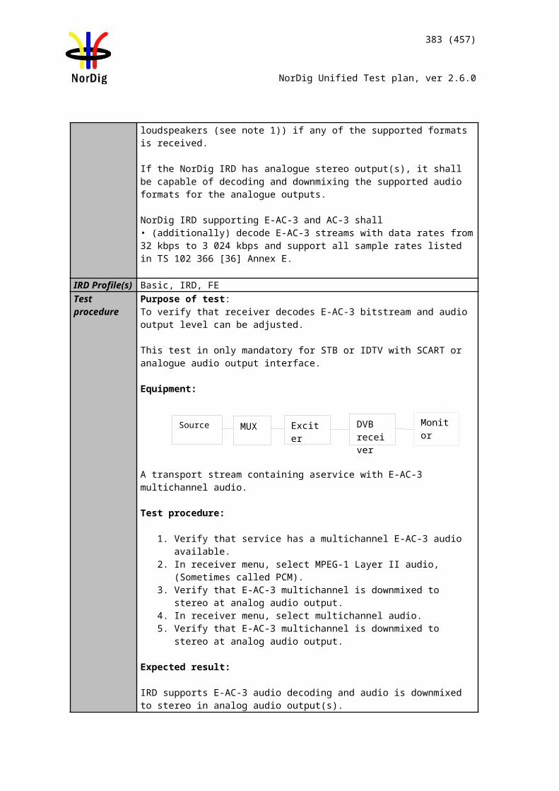
383 (457)
NorDig Unified Test plan, ver 2.6.0
problems with the receiver8. Verify that the EIT p/f has prority over EIT schedule in navigator (in case if the
EIT p/f and EIT schedule has a conflict in EIT information)9.
Expected result: EIT information is displayed correctly as signalled in EIT actual/other p/f and schedule for following descriptors:Short_event_descriptorComponent_descriptorExtend_event_descriptorParental_rating_descriptor
Test result(s)NOK OR OK
The services and events can be presented to viewer.EIT information is cross-distributed and it is visible to viewer. (MUX1 EIT information can be seen when receiver is tuned to a service on MUX2. Also the MUX2 EIT information can be seen when receiver is tuned to a service on MUX1).
Conformity OK Fault Major Minor, define fail reason in commentsComments If possible describe if fault can be fixed with software update: YES NO
Describe more specific faults and/or other information
Date Sign
Test Case Task 11:24 PMT Descriptors - General
Section NorDig Unified 12.6.2Requirement The following descriptors are used in PMT:
Video_stream_descriptorCA_descriptorISO_639_language_descriptorPrivate_data_indicator_descriptorStream_identifier_descriptorTeletext_descriptorSubtitling_descriptorPrivate_data_specifier_descriptor
Audio_stream_descriptor (optional)Target_background_descritor (optional)Video_window_descritor (optional)
IRD Profile(s) Basic, IRD, FETest procedure Purpose of test:
To check the support for the following descriptors:Video_stream_descriptor
384 (457)
NorDig Unified Test plan, ver 2.6.0
CA_descriptorISO_639_language_descriptorPrivate_data_indicator_descriptorStream_identifier_descriptorPrivate_data_specifier_descriptor
Equipment:
Service1 Service2 FrequencyMUX1TS_id 1Network_id 1ON_id 1)
SID 1100S_name Test11S_type 0x01PMT PID 1100V PID 1109A PID 1108LCN 1 visible
SID 1200S_name Test12S_type 0x01PMT PID 1200V PID 1209A PID 1208LCN 2 visible
Can be chosen depending of the distribution media
MUX2TS_id 2Network_id 2ON_id 1)
SID 2100S_name Test21S_type 0x01PMT PID 2100V PID 2109A PID 2108LCN 3 visible
SID 2200S_name Test22S_type 0x01PMT PID 2200V PID 2209A PID 2208LCN 4 visible
Can be chosen depending of the distribution media, but cannot be same as in MUX1
1) ON_id (Original_network_id) can be chosen in range 0x0001-0xfe00 (operational network) and it shall be same for both muxes2)Network_id for DVB-C and DVB-S/S2 IRD tests shall be same in all muxes
Test procedure:
1. Control that the MUX1 has a service with descriptors signalled above2. Zap to this service and check quickly that it works.
Expected result:All components in the service are able to decode.
Test result(s)Conformity OK Fault Major Minor, define fail reason in commentsComments If possible describe if fault can be fixed with software update: YES NO
Describe more specific faults and/or other information
Date Sign
MUX 1
MUX 2
Exciter 1
Exciter 2Combiner DVB
receiver
TS Source 2
TS Source 1
SI management system
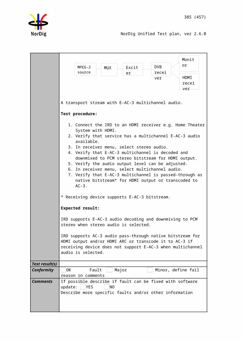
385 (457)
NorDig Unified Test plan, ver 2.6.0
Test Case Task 11:25 PMT Descriptors – teletext pages, teletext subtitling and DVB subtitling
Section NorDig Unified 12.6.2Requirement The following descriptors are used in PMT:
teletext_descriptorsubtitling_descriptor
IRD Profile(s) Basic, IRD, FETest procedure
This requirement is tested in Test Task 8
Test Case Task 11:26 Dynamic update of PMT PID values
Section NorDig Unified 12.1Requirement The NorDig IRD shall at least start action for any changes in the received "dynamic" PSI
and SI data, (PMT, EIT, TDT/TOT, running status and CA mode) within 1 second. (As a guideline for the implementation, the trigger for changes in received tables can be based on comparing the 'version id' in the tables)
IRD Profile(s) Basic, IRD, FETest procedure Purpose of test:
To verify that the receiver is able to maintain reception when PID values in PMT are dropped, added or changed.
Equipment:
Service1 Service2 FrequencyMUX1TS_id 1Network_id 1ON_id 1)
SID 1100S_name Test11S_type 0x01PMT PID 1100V PID 1109 incl PCRA PID 1108Teletext PID 1107DVB Subt PID 1106LCN1visible
SID 1200S_name Test12S_type 0x01PMT PID 1200V PID 1209 incl PCRA PID 1208Teletext PID 1207DVB Subt PID 1106LCN 2 visible
Can be chosen depending of the distribution media
1) ON_id (Original_network_id) can be chosen in range 0x0001-0xfe00 (operational network)
Sometimes broadcaster may drop, add or change the content of the PID. If this happens, the PMT is updated by changing the version_id.
Test procedure:
MUX 1
MUX 2
Exciter 1
Exciter 2Combiner DVB
receiver
TS Source 2
TS Source 1
SI management system
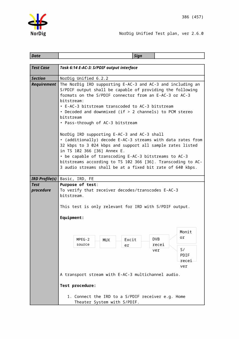
386 (457)
NorDig Unified Test plan, ver 2.6.0
1. Control that the MUX1 and MUX2 have services signaled as defined in table above
2. Zap all the services and check quickly that they work. 3. Drop all PIDs on Service1 on MUX1.4. Zap to service1 in MUX15. Add PIDs in following order:
a. Video PID 1109b. Audio PID 1108c. Teletext PID1107d. DVB subtitling PID 1106
6. Verify that the service is decoded correctly by watching the video, listening the audio and reading the teletext, teletext subtitling and DVB subtitling
7. Change the following PID values:a. Video PID 1109 to 1103b. Audio PID 1108 to 1102
Expected result:After addition of the PIDs, all the component in the service are decoded correctly.
Change of PID values maintains the service decoding.
Test result(s)Conformity OK Fault Major Minor, define fail reason in commentsComments If possible describe if fault can be fixed with software update: YES NO
Describe more specific faults and/or other information
Date Sign
Test Case Task 11:27 Dynamic update of PMT-Component priority (stream type)
Section NorDig Unified 12.6.3Requirement
NorDig IRDs shall ignore advanced audio streams when it does not support such decod-ing those streams. For example, an IRD that do not include any AC-3 (down-mix) decoder, (maybe only supports pass-through of AC-3 to the digital audio output), shall not choose the AC-3 au-dio stream as default. Instead it shall choose among the IRDs supported audio stream types according to chapter 6.5, Audio prioritising. For video decoding, NorDig IRDs shall select the service’s video components, and set the default setting in accordance with the priority list in Table 6.1.
IRD Profile(s) Basic, IRD, FETest procedure
Purpose of test:To verify that the receiver is able select video and audio components in priority order.
Equipment:
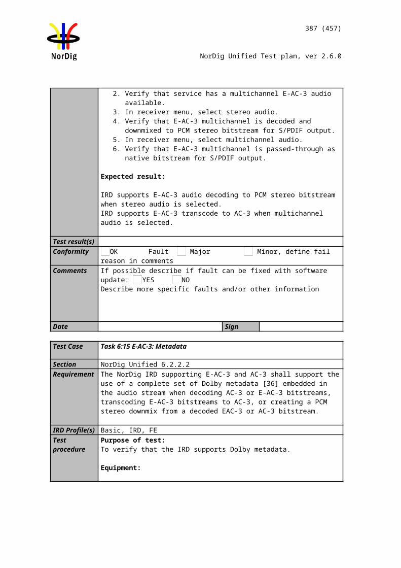
MPEG source
MUX1
Exciter DVB receiver
387 (457)
NorDig Unified Test plan, ver 2.6.0
The idea in this test is that there is always video and audio available in the receiver output or IDTV’s integrated display / speakers independently which input video and audio format(s) is(are) available in the service.
Depending of the audio selection settings (stereo or multichannel) in receiver menu system receiver shall output always audio in the correct format in the physical audio output or IDTV’s integrated speakers..
MPEG source must have capability to simultaneously with
* video component broadcast for following video formats: MPEG-2 MP@ML (SD) MPEG-4 AVC HP@L4 (HD) MPEG-4 AVC HP@L4 / L3 (SD)
* audio component broadcast for following audio formats: MPEG-1 Layer II MPEG-4 HE AAC AC-3 E-AC-3
Service1 Service2 FrequencyMUX1TS_id 1Network_id 1ON_id 1)
SID 1100S_name Test11PMT PID 1100V PID 1109 (MPEG 2 SD)V PID 1119 (AVC HD)V PID 1129 (AVC SD)
A PID 1108 (MPEG1 L2)A PID 1118 (HE AAC)A PID 1128 (E-AC-3)A PID 1138 (AC-3)
Logical_chan_desc 1visible
SID 1200S_name Test12PMT PID 1200V PID 1209 incl PCRA PID 1208Teletext PID 1207DVB Subt PID 1106Logical_chan_desc 2 visible
Can be chosen depending of the distribution media
1) ON_id (Original_network_id) can be chosen in range 0x0001-0xfe00 (operational network)
The service PCR is broadcasted in separate PID.
Test procedure:
1. Control that the MUX1 have services signaled as defined in table above2. Zap all the services and check quickly that they works. 3. Zap to service1 in MUX14. Drop PIDs in following order:
a. Video PID 1119b. Video PID 1129c. Audio PID 1118d. Audio PID 1128e. Audio PID 1138
5. Add PIDs in following order:a. Video PID 1129
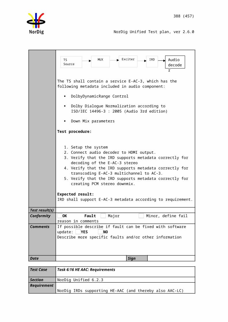
388 (457)
NorDig Unified Test plan, ver 2.6.0
b. Video PID 1119c. Audio PID 1138d. Audio PID 1128e. Audio PID 1118
6. Verify that the service is decoded correctly by watching the video, listening the audio
Expected result:
HDTV receiver: After remove and addition of the PIDs, all the component in the service are decoded correctly.
SDTV receiver: stream_types not supported by the receiver are not affecting the receiver operability.
Test result(s)Video codecs:
Video codec Stream_type Priority OK/NOK
MPEG-4 AVC HP@L4 HD video stream
0x1B 1 (highest)
MPEG-4 AVC HP@L4 / L3 SD video stream
0x1B 2
Basic, MPEG-2 MP@ML video stream (or MPEG1)
0x02 (0x01) 3 (lowest)
Audio codecs:
Audio codec Stream_type Priority OK/NOK
MPEG-4 HE.AAC (or LC.AAC) v2 audio stream
0x11 1 (highest)
E-AC-3 (Enhanced AC-3) audio stream
0x06 2
AC-3 (AC-3) audio stream 0x06 3
Basic, MPEG-1 Layer II audio stream
0x03 4 (lowest)
Conformity OK Fault Major Minor, define fail reason in commentsComments If possible describe if fault can be fixed with software update: YES NO
Describe more specific faults and/or other information
Date Sign
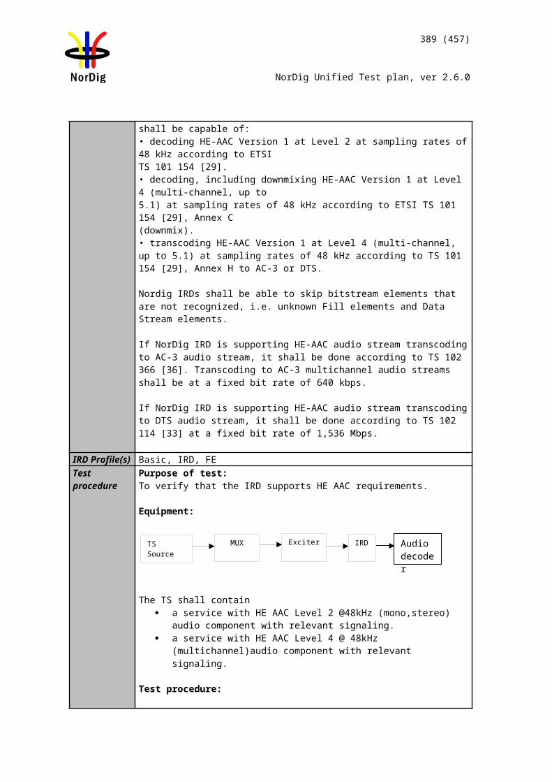
389 (457)
NorDig Unified Test plan, ver 2.6.0
Test Case Task 11:28 Dynamic update of PMT - Content_Protection_descriptor
Section NorDig Unified 12.6.7Requirement This descriptor is used to signal the content protection level for the received service, see
Table 12.29.The IRD shall use the signalled Content Protection level together with the IRD’s HDCP user setting todetermine if HDCP shall be enabled or disabled on the HDMI output inter-face, see section 8.6.4.The Content Protection descriptor shall be conveyed in the descriptor loop immediately following theprogram_info_length field in the Program Map Table. The descriptor only applies to the service to whichthe program map table is applicable. If the descriptor is missing for a service, it shall be interpreted ascontent protection level 0x01 (see Table 12.29).
IRD Profile(s) Basic, IRD, FETest procedure
This requirement is tested in TestTask 9:7
Test Case Task 11:29 Dynamic update of TDT/TOT
Section NorDig Unified 12.5Requirement The NorDig IRD shall have a real time clock and time/date (calendar) running
continuously. Thetime/date (calendar) shall be updated by incoming TDT and TOT from SI. NorDig IRD shall display thecorrect time for each country based on TDT, TOT, and the country name selected by the user.
IRD Profile(s) Basic, IRD, FETest procedure Purpose of test:
To verify that the real time clock runs continously.
Equipment:
Test procedure for continuously running clock / calendar:
1. Connect and start up the instruments2. Make sure that the TDT (Time and Date Table) and TOT (Time Offset Table)
are present in the transport stream.3. Locate the time and date display.4. Check if the time and date is updated and fill in the test protocol. (Date can be
tested separately and filled later in the test protocol).
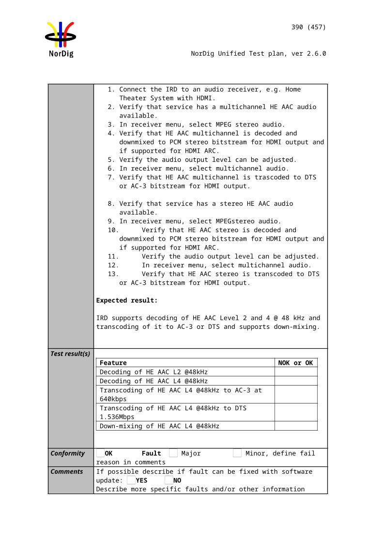
390 (457)
NorDig Unified Test plan, ver 2.6.0
Expected result:The time and date shall be displayed and updated in the navigator as time goes by.
Purpose of test:
To test that the real time clock is updated from TDT and TOT information.
Equipment:
As in previous test.
Example of the configuration of the local_time_offset descriptor in the TOT for Sweden and from summertime to wintertime change. Date of the change is 28/10/2001 and time 01:00:00 o’clock.
Test procedure Updated clock by TDT and TOT:
(Use traditional calendar to find out dates and times for the next wintertime and summertime changes.)
1. Connect and start up the instruments2. Make sure that the TDT (Time and Date Table) and TOT (Time Offset Table) is
present in the transport stream.3. Configure the TOT without local_time_offset decriptor. Configure the TDT in
the transport stream as it is specified in the test protocol. 4. Turn on receiver.5. Wait for the change of the year.6. Locate the time and date display. 7. Check the time and date in the navigator.8. Fill in the result and NOK or OK in the test protocol. 9. Turn off receiver.10. Configure TOT local_time_offset descriptor for the next change to wintertime/
summertime. Set UTC_time in the TDT few minutes before actual change. Make sure the same UTC_time is used in TOT.
11. Turn on receiver.12. Check the time and date in the navigator. 13. Fill in the test date and time, result date and time and NOK or OK in the proto-
col.14. Turn off receiver.15. Configure TOT local_time_offset descriptor for the next change to
summertime/wintertime after the date used in test point 10. Set UTC_time in the TDT few minutes before that change. Make sure the same UTC_time is used in TOT.
16. Turn on receiver.17. Check the time and date in the navigator.18. Fill in the test date and time, result date and time and NOK or OK in the proto-
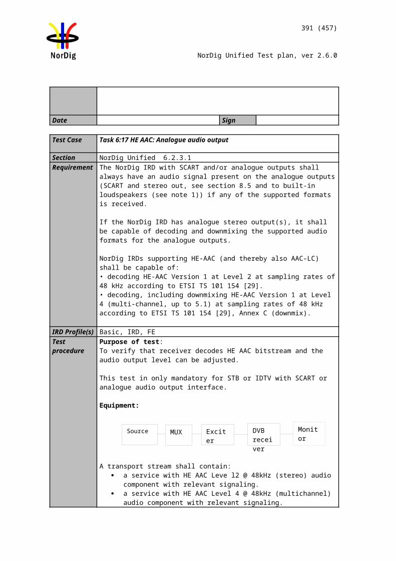
391 (457)
NorDig Unified Test plan, ver 2.6.0
col.19. Repeat test points 14 to 18 using country codes for ICE (Iceland), DNK (Den-
mark), FIN (Finland) and NOR (Norway).
Expected result:All test results fulfills the expected results as defined in the specification.
Test result(s) Test procedure for continuously running clock / calendar :
Test procedure Updated clock by TDT and TOT:Test points 1-8. (TDT test)
Test points 9-13. (TOT test)
Test points 14-19. (TOT test)
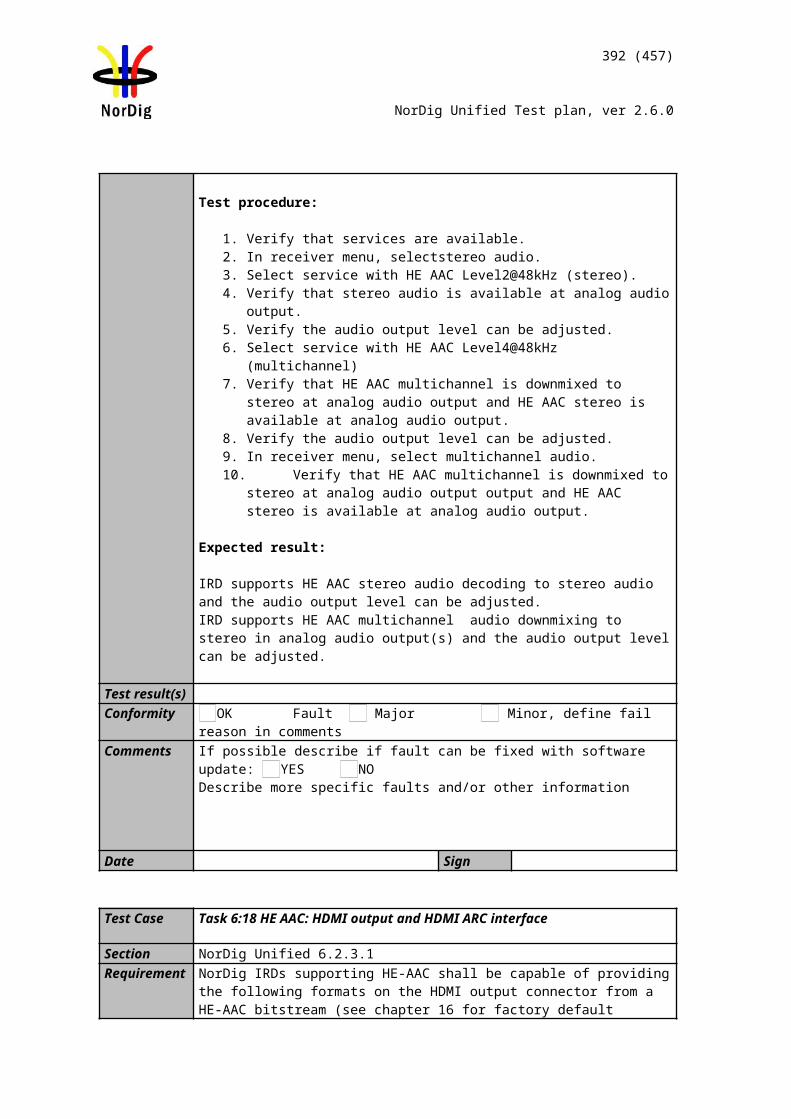
392 (457)
NorDig Unified Test plan, ver 2.6.0
Conformity OK Fault Major Minor, define fail reason in commentsComments If possible describe if fault can be fixed with software update: YES NO
Describe more specific faults and/or other information
Date Sign
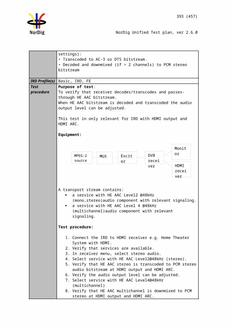
393 (457)
NorDig Unified Test plan, ver 2.6.0
2.13 Task 14: Navigator
Test Case Task 12:1 Navigator: General
Section NorDig Unified 13.1 and 16Requirement The NorDig IRD shall implement a basic Navigator, which provides user access to
system information, and allows the user to control the operation of the IRD. The Navigator is by definition part of the system software.
The Navigator shall include a service list function and a basic Event Schedule Guide.
The Navigator shall also initiate bootloading
The Naviagator shall support the Nordic and English languages.
IRD Profile(s) Basic, IRD, FETest procedure Purpose of test:
To test the existent of the Navigator functions.
Initiating of bootloading in Navigator is tested in test taskError: Reference source not found.
Equipment:
Test procedure:
1. Start the Navigator. 2. Check that it displays the valid services and allow control of the IRD. 3. Check that a service list is presented and that EIT p/f is displayed.4. Verify navigator supports Nordic and English languages.5. Verify that navigator has user setting for the preferences
Expected result:
The Navigator is present and complies with the requirement defined above.
Verify initiating of bootloading is tested in Task 6.1.
Test result(s)Conformity OK Fault Major Minor, define fail reason in commentsComments If possible describe if fault can be fixed with software update: YES NO
Describe more specific faults and/or other information
Date Sign
394 (457)
NorDig Unified Test plan, ver 2.6.0
2.13.1 Static PSI/SI data
Test Case Task 12:2 Service list - General requirement
Section NorDig Unified 13.2.1Requirement The service list shall be displayed to the user. The user shall be able to select a service
from the displayedservice list. The selected service shall appear immediatelyIRD Profile(s) Basic, IRD, FETest procedure Purpose of test:
To verify that the service list containsservices and they are accessible.
Equipment:
Test procedure:
Start the Navigator and go through and select all services in the list in a random pattern.
Expected result:Verify that all services are accessible.
Test result(s)Conformity OK Fault Major Minor, define fail reason in commentsComments If possible describe if fault can be fixed with software update: YES NO
Describe more specific faults and/or other information
Date Sign
Test Case Task 12:3 Service list – service types and categories
Section NorDig Unified 12.1.4 and 12.1.5 and 13.2.1.1Requirement The NorDig IRD shall minimum handle the service types listed in Table 12.1.
Service types that are not supported by the NorDig IRD should be ignored. (If the (SDTV) IRD do not support MPEG-4 AVC video decoder, it should not list/install within the TV service list service types for advanced codec; 0x16 and 0x19).
The services are group into three service type categories; TV (1), Radio (2) and Others/data (3) services:(1) TV category includes services with service type; 0x01 digital (MPEG-2) TV service, 0x16 advanced codec SD TV service and 0x19 advanced codec HD TV service. (2) Radio category includes services with service type; 0x02 digital radio sound service and 0x0A advanced codec digital radio sound service. (3) Others/(data) category includes all other service types that are not included in
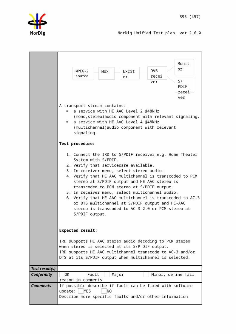
395 (457)
NorDig Unified Test plan, ver 2.6.0
TV (1) and Radio (2) categories.
The NorDig IRD (1) shall during installation of services create a common service list for each category (i.e. all 0x01, 0x16 and 0x19 within same TV category list and so on for the Radio and Other/data categories).
The IRD shall build up different sections inside one service list or build up several service lists, one for each different service_type as the default IRD service_list(s).
IRD Profile(s) Basic, IRD, FETest procedure Purpose of test:
To test that the different type of services are located on different lists.
Equipment:
Service1 Service2 Service3 FrequencyMUX1 TS_id 1Network_id 1ON_id 1)
SID 1100Service type 0x01S_name Test11PMT PID 1100V PID 1109A PID 1108LCD: 1 visibleEncrypted
SID 1200Service type 0x02S_name Test12PMT PID 1200
A PID 1208LCD: 2 visibleClear
SID 1300Service type 0x0CS_name Test13PMT PID 1300V PID 1309A PID 1308LCD: 3 visibleClear
Can be chosen depending of the distribution media
MUX2 TS_id 2Network_id 22)
ON_id 1
SID 2100Service type 0x16S_name Test21PMT PID 2100V PID 2109A PID 2108LCD: 4 visibleClear
SID 2200Service type 0x19S_name Test22PMT PID 2200V PID 2209A PID 2208LCD: 5 visibleClear
SID 2300Service type 0x0AS_name Test23PMT PID 2300
A PID 2308LCD: 6 visibleClear
Can be chosen depending of the distribution media
1) ON_id (Original_network_id) can be chosen in range 0x0001-0xfe00 (operational network) and it shall be same for both muxes and it shall be same for both muxes2)Network_id for DVB-C and DVB-S/S2 IRD tests shall be same in all muxes
Channel list ID is set to 1 and country_code according to country settings in the receiver. Services in MUX1 are using MPEG-2 video and MPEG1 LII audio.Services in MUX2 are allowed only use advanced coded video and audio, with other words MPEG-4 AVC video and HE-AAC or E-AC-3 audio.
MUX 1
MUX 2
Exciter 1
Exciter 2Combiner STB
TS Source 2
TS Source 1
SI management system
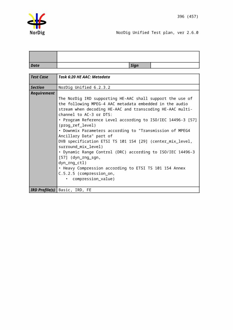
396 (457)
NorDig Unified Test plan, ver 2.6.0
Test procedure:
1. Verify that the services on MUX1 and MUX2 have service types digital television services, digital radio service and data broadcast service according to table above.
2. Perform re-initialisation if needed. 3. Check the service lists. 4. Fill in the measurement record.
Expected result:Different types of services are available on different category lists according to requirement.
Categories are ‘TV’, ‘Radio’, and ‘Data/Other’ services.
Optionally SDTV receiver doesn’t store HDTV services.
Test result(s)Measurement record:
SDTV receiverPos ‘TV’ ‘Radio’ ‘Data/Other’ NOK or OK1 Test112 Test123 Test13
HDTV receiverPos ‘TV’ ‘Radio’ ‘Data/Other’ NOK or OK1 Test112 Test123 Test134 Test215 Test226 Test23
Conformity OK Fault Major Minor, define fail reason in commentsComments If possible describe if fault can be fixed with software update: YES NO
Describe more specific faults and/or other information
Date Sign
Test Case Task 12:4 Service list – use of NIT_other and SDT_other
Section NorDig Unified 13.2.2 and 13.2.3Requirement The NorDig IRD shall make use of the descriptors listed in below in all NIT_actual (the
transport stream the NorDig IRD is tuned to) and NIT_other (other transport stream) tables available in order to update the service list (system delivery data, number of trans-port streams, logic channel number etc).
NIT descriptors:
Network_name_descriptor
397 (457)
NorDig Unified Test plan, ver 2.6.0
Satellite_delivery_system_descriptorCable_delivery_system_descriptorTerrestrial_delivery_system_descriptor
T2_delivery_system_descriptorService_list_descriptor
(Nordig) Logical_channel_descriptor
A Navigator shall never display services that the IRD is not able to receive or decode except for descrambling.
The IRD shall use the descriptors listed in table 13.2 from both SDT_actual and SDT_other tables to update the service list (service names etc.).
IRD Profile(s) Basic, IRD, FETest procedure Purpose of test:
To verify that the services, which are not able to receive, but signaled in SDT_other and/or NIT_other, are not visible in service list.
Equipment:
Service1 Service2 FrequencyMUX1TS_id 1Network_id 1ON_id 1)
SID 1100S_name Test11PMT PID 1100V PID 1109A PID 1108Logical_chan_desc 1 visible
SID 1200S_name Test12PMT PID 1200V PID 1209A PID 1208Logical_chan_desc 2 visible
Can be chosen depending of the distribution media.
MUX2TS_id 2Network_id 2ON_id 1)
SID 2100S_name Test21PMT PID 2100V PID 2109A PID 2108Logical_chan_desc 3 visible
SID 2200S_name Test22PMT PID 2200V PID 2209A PID 2208Logical_chan_desc 4 visible
Can be chosen depending of the distribution media. Not same as for Exciter 1
1) ON_id (Original_network_id) can be chosen in range 0x0001-0xfe00 (operational network) and it shall be same for both muxes2)Network_id for DVB-C and DVB-S/S2 IRD tests shall be same in all muxes
Following tables are signaled in both MUX: SDT_actual and SDT_other NIT_acutal inclusive service_list
MUX 1
MUX 2
Exciter 1
Exciter 2Combiner STB
TS Source 2
TS Source 1
SI management system
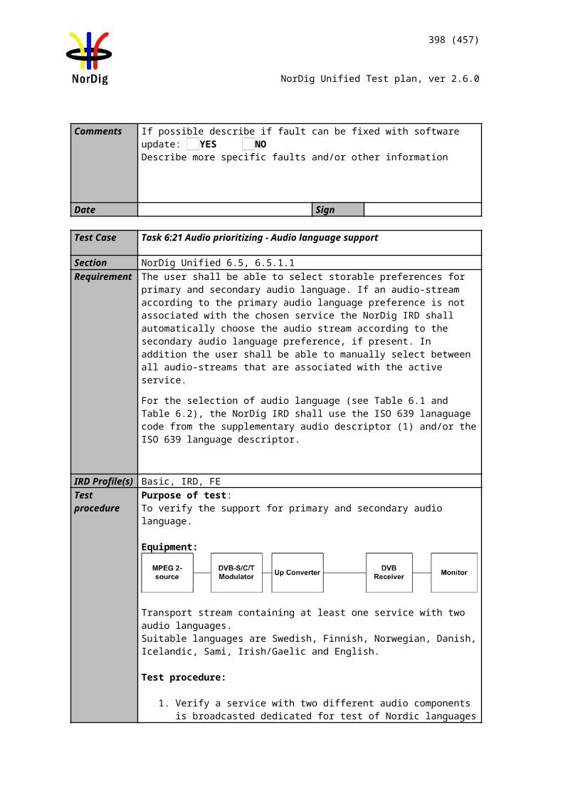
398 (457)
NorDig Unified Test plan, ver 2.6.0
NIT_other inclusive service_listWith following information content:
In MUX1, the SDT_actual corresponds the SDT_other in MUX2. In MUX2, the SDT_actual corresponds the SDT_other in MUX1 In MUX1, the NIT_actual corresponds the NIT_other in MUX2 In MUX2, the NIT_acutal corresponds the NIT_other in MUX1
With other words, the SDT and NIT information is cross-distributed between multiplexes.
Test procedure:The idea of the test is that for stationary reception, the services from the SDT_other and NIT_other service_list_description shall not be installed in the service list if the services are not able to be received.
1. Attenuate the output level of the exciter 1 to very low level or disconnect the output cable.
2. Clear all channels on service list (channel list in receiver). 3. Make new channel search.4. Verify that no services are installed carried within the transport stream through
MUX1. 5. Fill in the measurement record in test results.6. Increase the output level of the exciter1 to a output level that is able to be
received by the receiver. 7. Clear all channels on service list (channel list in receiver). 8. Make new channel search.9. Verify that all the services carried within transport stream from both MUX1
and MUX2 are installed in the service list (channel list in receiver).10. Zap to service1 in MUX1.
Expected result:Services that are not able to be received are not available in the service list (channel list).
Test result(s)Requirement NOK or OKServices are not listed in service list (channel list) when the services are not able to be received
Conformity OK Fault Major Minor, define fail reason in commentsComments If possible describe if fault can be fixed with software update: YES NO
Describe more specific faults and/or other information
Date Sign
Test Case Task 12:5 Service list - Inconsistent of SDT_actual and NIT_actual information
Section NorDig Rules Of Operation 2.6.2
399 (457)
NorDig Unified Test plan, ver 2.6.0
Requirement Optional descriptors:Service_list_descriptor
IRD Profile(s) Basic, IRD, FETest procedure Purpose of the test:
To verify if the IRD updates service list quasi-static from SDT_actual instead of NIT_actual service_list_descriptor.
Equipment:
Test procedure:
Service_list in NIT is optional to broadcast. Therefore, it is important to verify how the receiver extract information from the SDT_actual and NIT_actual service_list in case the information is inconsistent.
Transport stream shall have at least one service configured. The SDT_actual signalize the service, but the service_list_descriptor in NIT_actual shall not have the service listed.
Test procedure:1. Make first time installation of the IRD2. Verify the service_list_descriptor doesn’t list at least one of the services carried
within transport stream. With other words, there is inconsistent between SDT_actual and service_list_descriptor in NIT_actual
3. Verify that all the carried services within transport stream are in the service list.
Expected result:Services, carried within transport stream and listed in SDT_actual, are listed in service list independently if the services are listed in service_list_descriptor in NIT_actual.
Test result(s)Conformity OK Fault Major Minor, define fail reason in commentsComments If possible describe if fault can be fixed with software update: YES NO
Describe more specific faults and/or other information
Date Sign
Test Case Task 12:6 Service list – NIT_actual interpretation
Section NorDig Unified 13.2.2, 13.2.1.1Requirement The information in the descriptors specified in table 13.1 and table 13.2 shall be
displayed. The original network operator name may be omitted in case only one network is available.
Note: Table13.1 descriptors
Network_name_descriptorSatellite_delivery_system_descriptorCable_delivery_system_descriptorTerrestrial_delivery_system_descriptor
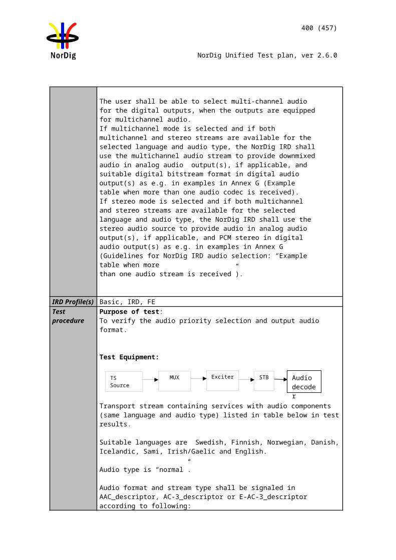
400 (457)
NorDig Unified Test plan, ver 2.6.0
T2_delivery_system_descriptorService_list_descriptor
(Nordig) Logical_channel_descriptorIRD Profile(s) Basic, IRD, FETest procedure Purpose of test:
To verify that the information in descriptors are displayed.
Equipment:
1)
ON_id (Original_network_id) can be chosen in range 0x0001-0xFE00 (operational network). Network_name NorDigTest
Test procedure:Start the Navigator.Check that the following information is available for all services:
network name, i.e. NorDigTest transmission parameters for respective distribution media service name, i.e. Test11 and Test12 on stored on channel positions 1 and 2. service type, i.e. Digital television service
Expected result:Verify that all the information specified above is available.
Test result(s)Conformity OK Fault Major Minor, define fail reason in commentsComments If possible describe if fault can be fixed with software update: YES NO
Describe more specific faults and/or other information
Date Sign
Test Case Task 12:7 Service list – NIT_actual original_network_ID
Section Nordig Unified 13.2.2Requirement Original_network_ID within 0xFF00-0xFFFF (temporary_private_use), shall only be
used for test and (shorter) demonstration transmission. Receiver will not install or display services within these original_network_ids.
IRD Profile(s) Basic, IRD, FETest procedure Purpose of test:
To test the reception in the test network.
Equipment:
Service1 Service2 FrequencyMUXTS_id 1Network_id 1ON_id 1)
SID 1100S_name Test11PMT PID 1100V PID 1109A PID 1108Logical_chan_desc 1 visible
SID 1200S_name Test12PMT PID 1200V PID 1209A PID 1208Logical_chan_desc 2 visible
Can be chosen depending of the distribution media
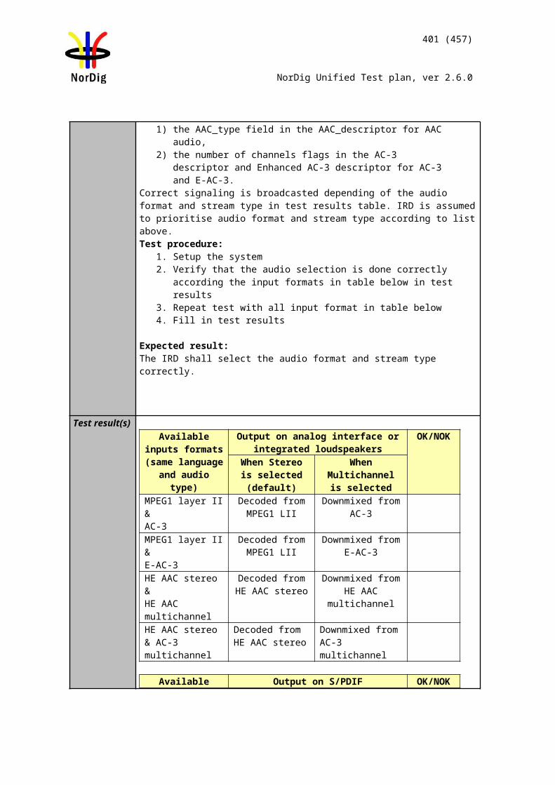
401 (457)
NorDig Unified Test plan, ver 2.6.0
1)
ON_id (Original_network_id) can be chosen in range 0x0001-0xfe00 (operational network) and it shall be same for both muxes.
Test procedure: 1. Turn on receiver. 2. Do re-initialization or make sure there are no services in channel list or in ESG. 3. Make sure that the ON_id is on the range of the operational network.4. Do channel search. 5. Check in channel list or ESG that the services are available.6. Change ON_id to 0xFF00. 7. Do re-initialization or make sure there are no services in channel list or in ESG.8. Do channel search. 9. Check that receiving ON_id 0xFF00/FFFF does not stop the scanning
procedure, this frequency is just skipped.10. Check in channel list or ESG that there are no services available. 11. Change ON_id to 0xFFFF. 12. Repeat from test point 7.
Expected result: Services are not available for ON-id range 0xFF00 – 0xFFFF.
Test result(s)Conformity OK Fault Major Minor, define fail reason in commentsComments If possible describe if fault can be fixed with software update: YES NO
Describe more specific faults and/or other information
Date Sign
Test Case Task 12:8 Service list – NIT_actual network_ID
Section Nordig Unified 13.2.2Requirement Network_ID within 0xFF01-0xFFFF (temporary_private_use), shall only be used for
test and (shorter) demonstration transmission. Receiver will not install or display services within these network_ids.
IRD Profile(s) Basic, IRD, FETest procedure Purpose of test:
To test the reception in the test network.
Equipment:
MUX Exciter STBMPEG 2 source
Service1 Service2 FrequencyMUXTS_id 1Network_id 1ON_id 1)
SID 1100S_name Test11PMT PID 1100V PID 1109A PID 1108Logical_chan_desc 1 visible
SID 1200S_name Test12PMT PID 1200V PID 1209A PID 1208Logical_chan_desc 2 visible
Can be chosen depending of the distribution media
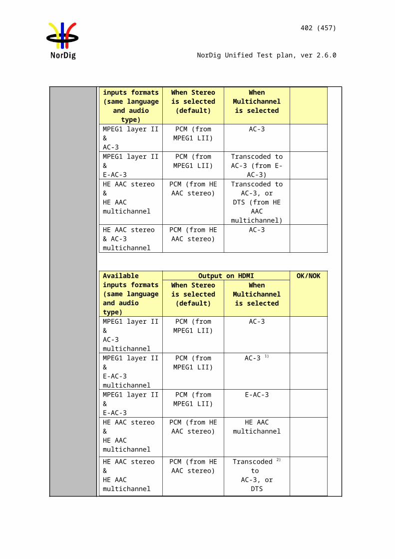
402 (457)
NorDig Unified Test plan, ver 2.6.0
Service2 Service2 FrequencyMUXTS_id 1Network_id 1)
ON_id 2)
SID 1100S_name Test11PMT PID 1100V PID 1109A PID 1108Logical_chan_desc 1 visible
SID 1200S_name Test12PMT PID 1200V PID 1209A PID 1208Logical_chan_desc 2 visible
Can be chosen depending of the distribution media.
1) Network_id on the range 0x0001 – 0xFDFF (operational network).2) ON_id (Original_network_id) can be chosen on range 0x0001-0xFE00 (operational network)
Test procedure:
1. Turn on receiver. 2. Do re-initialization or make sure there are no services in channel list or in ESG. 3. Make sure that the network_id is on the range of the operational network.4. Do channel search. 5. Check in channel list or ESG that there are no services available. 6. Change the network_id to 0xFF01.7. Do re-initialization or make sure there are no services in channel list or in ESG.8. Do channel search.9. Check that receiving network_id 0xFF01/FFFF does not stop the scanning
procedure, this frequency is just skipped.10. Check in channel list or ESG that there are no services available.11. Change the network_id to 0xFFFF.12. Repeat from test point 7.
Expected result:
Services are not available for network_id range 0xFF01 – 0xFFFF.Test result(s)Conformity OK Fault Major Minor, define fail reason in commentsComments If possible describe if fault can be fixed with software update: YES NO
Describe more specific faults and/or other information
Date Sign
Test Case Task 12:9 Service list – Inconsistent SDT_actual/NIT_actual and SDT_other/NIT_other
Section NorDig Rules Of Operation 2.6.2Requirement
IRD Profile(s) Basic, IRD, FETest procedure Purpose of the test:
To verify if the IRD updates service list quasi-static from SDT_actual instead of NIT_actual service_list_descriptor.
Equipment:
MUX Exciter STBTS Source
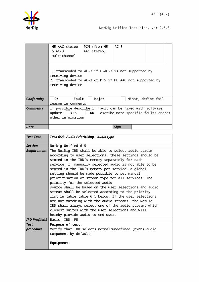
403 (457)
NorDig Unified Test plan, ver 2.6.0
Test procedure:
Service_list in NIT is optional to broadcast. Therefore, it is important to verify how the receiver extract information from the SDT_actual and NIT_actual service_list in case the information is inconsistent.
Transport stream shall have at least one service configured. The SDT_actual signalize the service, but the service_list_descriptor in NIT_actual shall not have the service listed.
Test procedure:1. Make first time installation of the IRD2. Verify the service_list_descriptor doesn’t list at least one of the services carried
within transport stream. With other words, there is inconsistent between SDT_actual and service_list_descriptor in NIT_actual
3. Verify that all the carried services within transport stream are in the service list.
Expected result:Services, carried within transport stream and listed in SDT_actual, are listed in service list independently if the services are listed in service_list_descriptor in NIT_actual.
Test result(s)Conformity OK Fault Major Minor, define fail reason in commentsComments If possible describe if fault can be fixed with software update: YES NO
Describe more specific faults and/or other information
Date Sign
Test Case Task 12:10 Service list – Handling of multiple channel lists from same networks and NorDig LCD
Section NorDig Unified 12.2.9.3.2Requirement The Logical Channel Descriptor version 2 enables transmission within same network of
multiple Channel lists, meaning that there might it be several channel lists available for a IRD to choose between. The NorDig IRD may treat each channel list as complete with all intended services for that network (original network id) and it is up to the broadcaster to ensure that all intended services are included in all lists.
The NorDig IRD shall at least store the sorting from one of the available Channel lists as default, but it is recommended that theNorDig IRD store all the transmitted Channel Lists sorting that matches the IRD’s country code settings (especially for IRDs that are not letting the user choose list during installation).
When several Channel Lists are available from same network (original network id) for the IRD during first time installation (or complete re-installation), the NorDig IRD shall choose the channel list as the default one with following priority:
1. The list with same country code as the IRD’s user preference setting’s country code. If several list available with same matching country code, the IRD shall choose the one with lowest list_id value OR let the viewer choose from a list, (typically using the
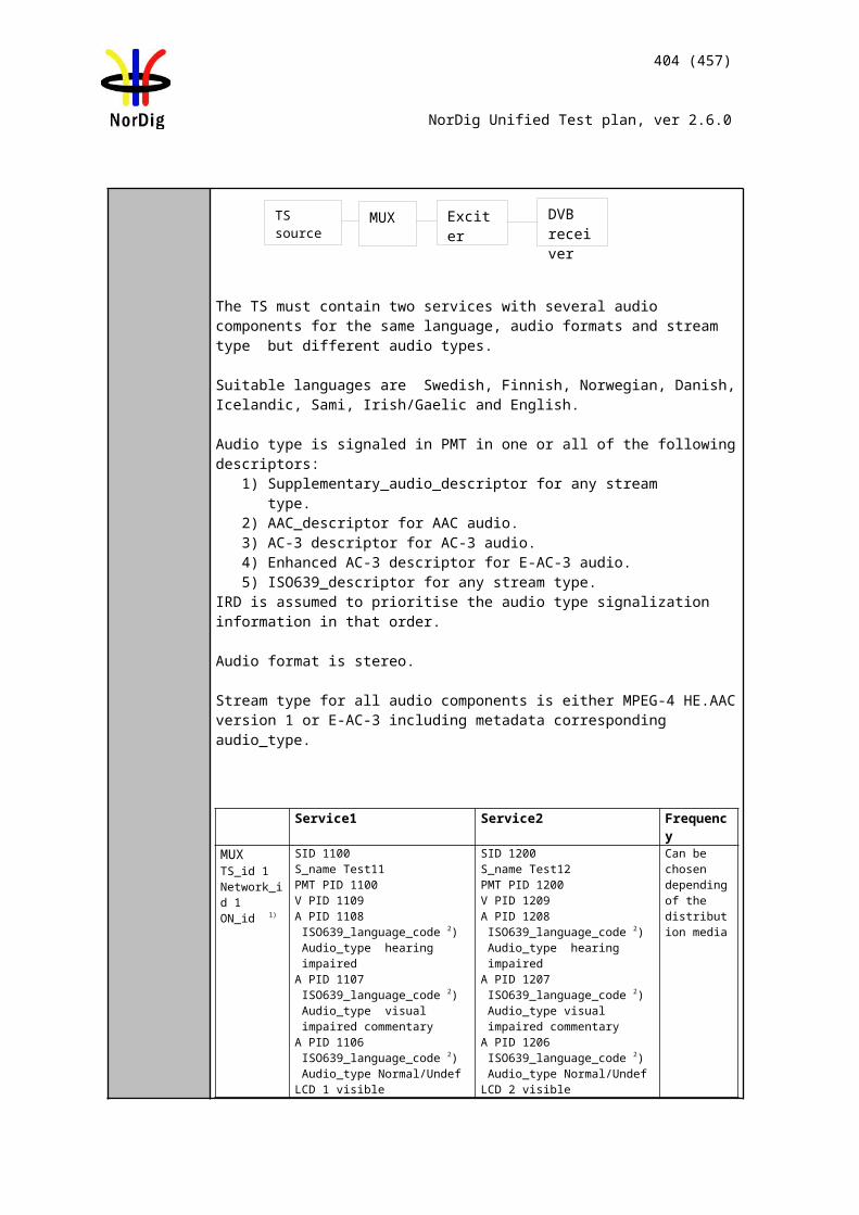
404 (457)
NorDig Unified Test plan, ver 2.6.0
channel_list_name)
2. If no Channel list has a country code that matches the user preference setting’s country code, theNorDig IRD shall let the viewer choose from a list (recommended) OR choose the one with lowest list_id value.
IRD Profile(s) Basic, IRD, FETest procedure Purpose of test:
To verify the support for the reception of multiple channel lists in one network.
Equipment:
Service1 Service2 FrequencyMUX1TS_id 1Network_id 1ON_id X 1)
SID 1100S_name Test11S_type 0x01PMT PID 1100V PID 1109A PID 1108
LCD v .2: 1 PRI SWELCD v.2: 2 PRI FINLCD v.2: 1 PRI NORLCD v.2: 1 PRI DNKLCD v.2: 4 PRI IRLLCD v.2: 5 SEC SWELCD v.2: 6 SEC FINLCD v.2: 5 SEC NORLCD v.2: 5 SEC DNKLCD v2: 8 SEC IRL
SID 1200S_name Test12S_type 0x01PMT PID 1200V PID 1209A PID 1208
LCD v .2: 2 PRI SWELCD v.2: 1 PRI FINLCD v.2: 3 PRI NORLCD v.2: 2 PRI DNKLCD v.2: 2 PRI IRLLCD v.2: 6 SEC SWELCD v.2: 5 SEC FINLCD v.2: 7 SEC NORLCD v.2: 6 SEC DNKLCD v2: 6 SEC IRL
Can be chosen depending of the distribution media
MUX2TS_id 2Network_id 2ON_id X 1)
SID 2100S_name Test21S_type 0x01PMT PID 2100V PID 2109A PID 2108
LCD v .2: 3 PRI SWELCD v.2: 3 PRI FINLCD v.2: 2 PRI NORLCD v.2: 4 PRI DNKLCD v.2: 3 PRI IRLLCD v.2: 7 SEC SWELCD v.2: 7 SEC FINLCD v.2: 6 SEC NORLCD v.2: 8 SEC DNKLCD v2: 7 SEC IRL
SID 2200S_name Test22S_type 0x01PMT PID 2200V PID 2209A PID 2208
LCD v .2: 4 PRI SWELCD v.2: 4 PRI FINLCD v.2: 4 PRI NORLCD v.2: 3 PRI DNKLCD v.2: 1 PRI IRLLCD v.2: 8 SEC SWELCD v.2: 8 SEC FINLCD v.2: 8 SEC NORLCD v.2: 7 SEC DNKLCD v2: 5 SEC IRL
Can be chosen depending of the distribution media, but cannot be same as in MUX1
1) ON_id (Original_network_id) can be chosen in range 0x0001-0xfe00 (operational network) and it shall be same for both muxes. 2)Network_id for DVB-C and DVB-S/S2 IRD tests shall be same in all muxes
MUX 1
MUX 2
Exciter 1
Exciter 2Combiner DVB
receiver
TS Source 2
TS Source 1
SI management system
405 (457)
NorDig Unified Test plan, ver 2.6.0
For satellite networks the channel lists represented in tables below are valid due to the capability to receive services within one and same ON_id in different countries where even different country_settings in receiver are relevant. The LCN is equal in all different channel lists IDs.
For cable and terrestrial networks, a subset of channel lists is required as long as one and same ON_id is in concern. Transmissions in these networks are not normally dedicated for receivers with different country settings. Therefore, two channel list (e.g. ListDNKpri and ListDNKsec) with same country_code is enough to test requirement in this test.
The channel list under test shall not be signaled with channel_list_ID 1. E.g. if receiver dedicated to Swedish market is under test, ListSWEpri shall be signaled with other channel_list_ID than 1 in order to avoid malfunction in receiver where the receiver selects first list found.
MUX1:Channel_list_ID Channel list name Country_code
1 ListSWEpri SWE2 ListFINpri FIN3 ListNORpri NOR4 ListDNKpri DNK5 ListIRLpri IRL6 ListSWEsec SWE7 ListFINsec FIN8 ListNORsec NOR9 ListDNKsec DNK10 ListIRLsec IRL
MUX2:
Channel_list_ID Channel list name Country_code1 ListSWEpri SWE2 ListFINpri FIN3 ListNORpri NOR4 ListDNKpri DNK5 ListIRLpri IRL6 ListSWEsec SWE7 ListFINsec FIN8 ListNORsec NOR9 ListDNKsec DNK10 ListIRLsec IRL
Test procedure:
Receiver country is equal as channel list country_code:
1. Perforn factory reset to the receiver2. Perform channel search3. Verify that the all services are found4. The channel list with lowest channel list ID is automaticly selected by the
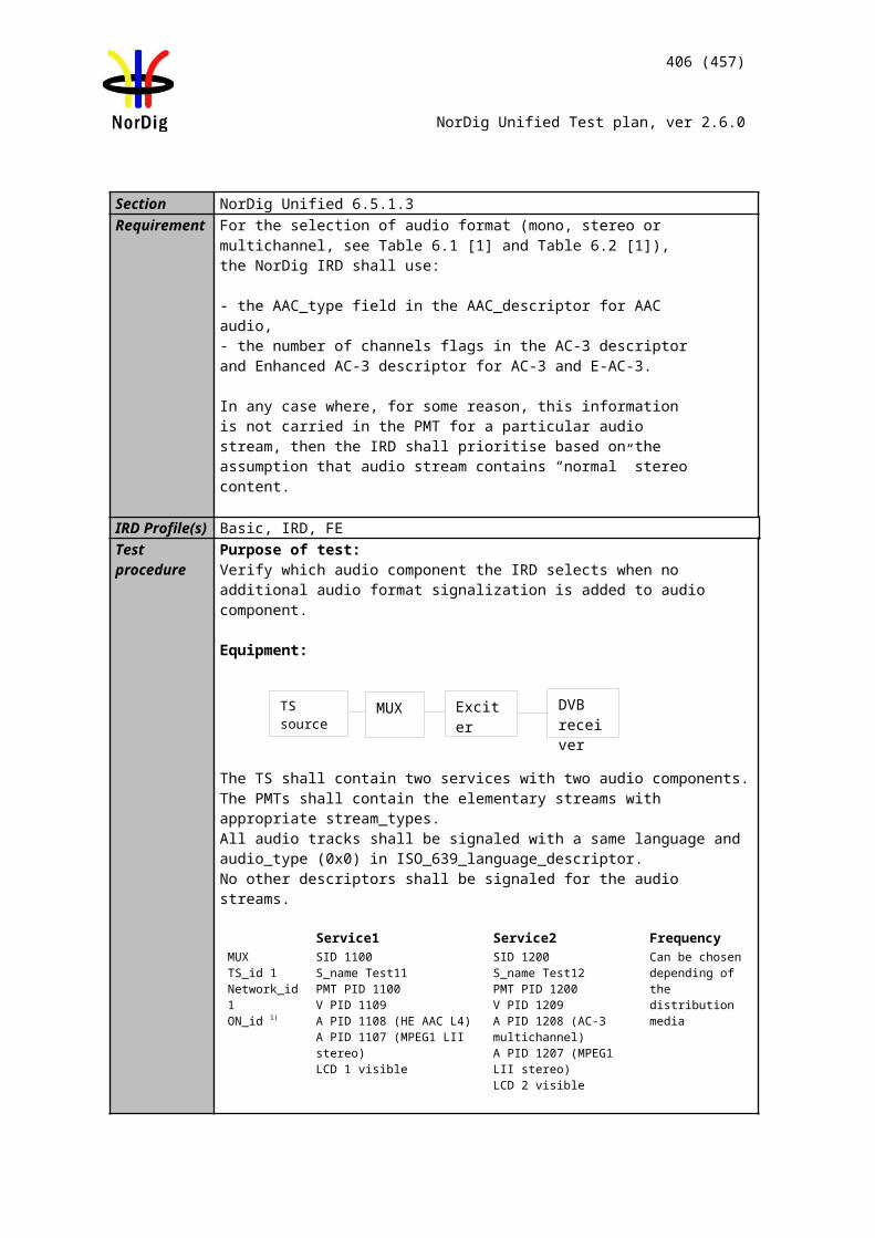
406 (457)
NorDig Unified Test plan, ver 2.6.0
receiver or the user is able to select the channel list.
Receiver country is not equal as channel list country_code:
5. Perforn factory reset to the receiver6. Perform channel search7. Verify that the all services are found8. The channel list is either user selectable or automaticly selected by the receiver
according to lowest channel list ID.
Expected result:
The channel list with same country code as the IRD’s user preference setting’s country code the IRD shall choose the one with lowest list_id value OR let the viewer choose from a list (typically using the channel_list_name).
If no Channel list has a country code that matches the user preference setting’s country code, the IRD shall let the viewer choose from a list (recommended) OR choose the one with lowest list_id value.
Service name
Logical channel position(
SWE)
Logical channel position (FIN)
Logical channel position (NOR)
Logical channel position (DNK)
Logical channel position (IRL)
Channel list
Test11 1 2 1 1 4 Either with
lowest channel list ID
(primary)or user selected
Test12 2 1 3 2 2Test21 3 3 2 4 3Test22 4 4 4 3 1
Test result(s)Conformity OK Fault Major Minor, define fail reason in commentsComments If possible describe if fault can be fixed with software update: YES NO
Describe more specific faults and/or other information
Date Sign
Test Case Task 12:11 Service list – Simultaneous transmission of LCD v1 and v2
Section NorDig Unified 12.2.9.4Requirement When broadcasting both LCD version 1 and version 2 within one Original Network ID,
the NorDig IRDsupporting both descriptors shall only sort according to the version 2 (i.e. NorDig LCD version 2 hashigher priority).
IRD Profile(s) Basic, IRD, FETest procedure Purpose of test:
To verify the support for simultaneous transmission of LCD ver.1 and Ver2.
Equipment:
407 (457)
NorDig Unified Test plan, ver 2.6.0
Service1 Service2 Service3 FrequencyMUX1TS_id 1Network_id 1ON_id 1)
SID 1100S_name Test11S_type 0x01PMT PID 1100V PID 1109A PID 1108LCN Ver.1: 1 visibleLCN Ver.2: 2 visible
SID 1200S_name Test12S_type 0x01PMT PID 1200V PID 1209A PID 1208LCN Ver.1: 2 visibleLCN Ver.2: 1 visible
SID 1300S_name Test13S_type 0x01PMT PID 1300V PID 1309A PID 1308LCN Ver.1: 3 visibleLCN Ver.2: 3 visible
Can be chosen depending of the distribution media
MUX2TS_id 2Network_id 2ON_id 1)
SID 2100S_name Test21S_type 0x01PMT PID 2100V PID 2109A PID 2108LCN Ver.1: 4 visibleLCN Ver.2: 5 visible
SID 2200S_name Test22S_type 0x01PMT PID 2200V PID 2209A PID 2208LCN Ver.1: - LCN Ver.2: -
Can be chosen depending of the distribution media, but cannot be same as in MUX1
1) ON_id (Original_network_id) can be chosen in range 0x0001-0xfe00 (operational network) and it shall be same for both muxes2)Network_id for DVB-C and DVB-S/S2 IRD tests shall be same in all muxes
Note: It is not obvious that network operators will broadcast different LCN in different version of LCD. However, for testing purposes, different LCNs are broadcasted.
Test procedure:
1. Perforn factory reset to the receiver2. Perform automatic channel search3. Verify that the all services are found4. Verify that the services are stored according the LCD version 2 signaling.
Expected result:The channel numbers are correct.
Service in service list should be stored as listed below:
Service name IRD supports version 2Test12 1Test11 2Test13 3Test21 5Test22 Last in the list
MUX 1
MUX 2
Exciter 1
Exciter 2Combiner DVB
receiver
TS Source 2
TS Source 1
SI management system
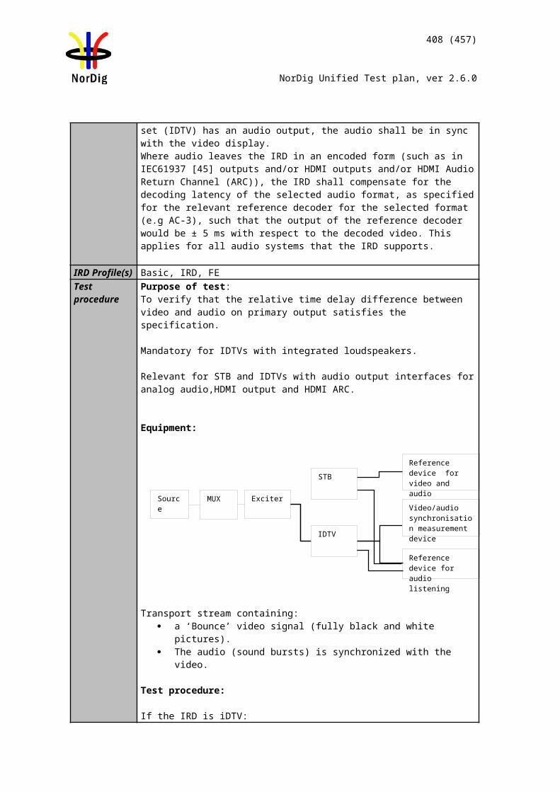
408 (457)
NorDig Unified Test plan, ver 2.6.0
Test result(s)Conformity OK Fault Major Minor, define fail reason in commentsComments If possible describe if fault can be fixed with software update: YES NO
Describe more specific faults and/or other information
Date Sign
Test Case Task 12:12 Service list – Simultaneous reception of multiple networks and NorDig LCD
Section NorDig Unified 12.2.9.5Requirement The NorDig IRD with terrestrial front-end shall be able to install several (DTT) original
networks (with different original network ids).For multiple original networks (original network ids) the NorDig IRD shall first sort/list all services from one original network (original network id) according to that LCD, be-fore sorting/listing the next original network. The first original network is the primary network and any additional received originalnetworks are referred to as secondary network(s).
The user shall be able to set which original network that shall be the primary, either via the user preferences, e.g. matching country setting (preferred) or via user selectable list of available original networks or similar mechanism. In order to simplify this, the NorDig IRD should map/translate the original network id into the country name. This means that for IRD where the user has set the country setting, the primary network should automatic be the country matching the original network id (and its services shall be listed first in the NorDig IRD’s service list).
IRD Profile(s) Basic, IRD, DVB-T, DVB-T2Test procedure
Purpose of test:To verify the support for the reception of multible networks and NorDig LCN.
Equipment:
Service1 Service2 Service3 FrequencyMUX1TS_id 1Network_id 1ON_id X 1)
SID 1100S_name Test11S_type 0x01PMT PID 1100V PID 1109A PID 1108LCN 2 visible
SID 1200S_name Test12S_type 0x01PMT PID 1200V PID 1209A PID 1208LCN 5 visible
SID 1300S_name Test13S_type 0x01PMT PID 1300V PID 1309A PID 1308LCN 6 visible
Can be chosen depending of the distribution media
MUX 1
MUX 2
Exciter 1
Exciter 2Combiner DVB
receiver
TS Source 2
TS Source 1
SI management system
409 (457)
NorDig Unified Test plan, ver 2.6.0
MUX2TS_id 2Network_id 2ON_id Y 1)
SID 2100S_name Test21S_type 0x01PMT PID 2100V PID 2109A PID 2108LCN 2 visible
SID 2200S_name Test22S_type 0x01PMT PID 2200V PID 2209A PID 2208LCN 4 visible
SID 2300S_name Test23S_type 0x01PMT PID 2300V PID 2309A PID 2308LCN 7 visible
Can be chosen depending of the distribution media, but cannot be same as in MUX1
1) ON_id (Original_network_id) can be chosen in range 0x0001-0xfe00 (operational network). Values for X and Y shall be selected different.
Note for services belonging to secondary ON_id: SDT_actual service order shall not be equal with LCN number order because this may result to a situation that the receiver has sorted the services according to SDT_actual service order instead of the LCN number order.
Test procedure:
1. Perform factory reset to the receiver2. The primary network is either user selectable or automaticly based on the
country settings in the receiver.3. Perform channel search4. Verify that the all services are found5. Verify that the services are ordered firstly by the ON_id and secondly by the
LCD.
Expected result:User is able to select which network is the primary network.
The channel numbers are correct.
Service in service list should be stored as listed below:
Service name ON_id X as primary
ON_id Y as primary
Test11 2 Last in the list e.g. 8Test12 5 Last in the list e.g. 9Test13 6 Last in the list e.g. 10Test21 Last in the list, e.g. 7 2Test22 Last in the list, e.g. 8 4Test23 Last in the list, e.g. 9 7
Test result(s)Conformity OK Fault Major Minor, define fail reason in commentsComments If possible describe if fault can be fixed with software update: YES NO
Describe more specific faults and/or other information
Date Sign
Test Case Task 12:13 Service list - Priority of LCN between SD and HDTV services
Section NorDig Unified 12.2.9.2.3, 12.2.9.3.4 and 13.2Requirement If several services are allocated to the same logic_channel_number, (within the same
channel list, as may be the case if several terrestrial regions can be received at the same
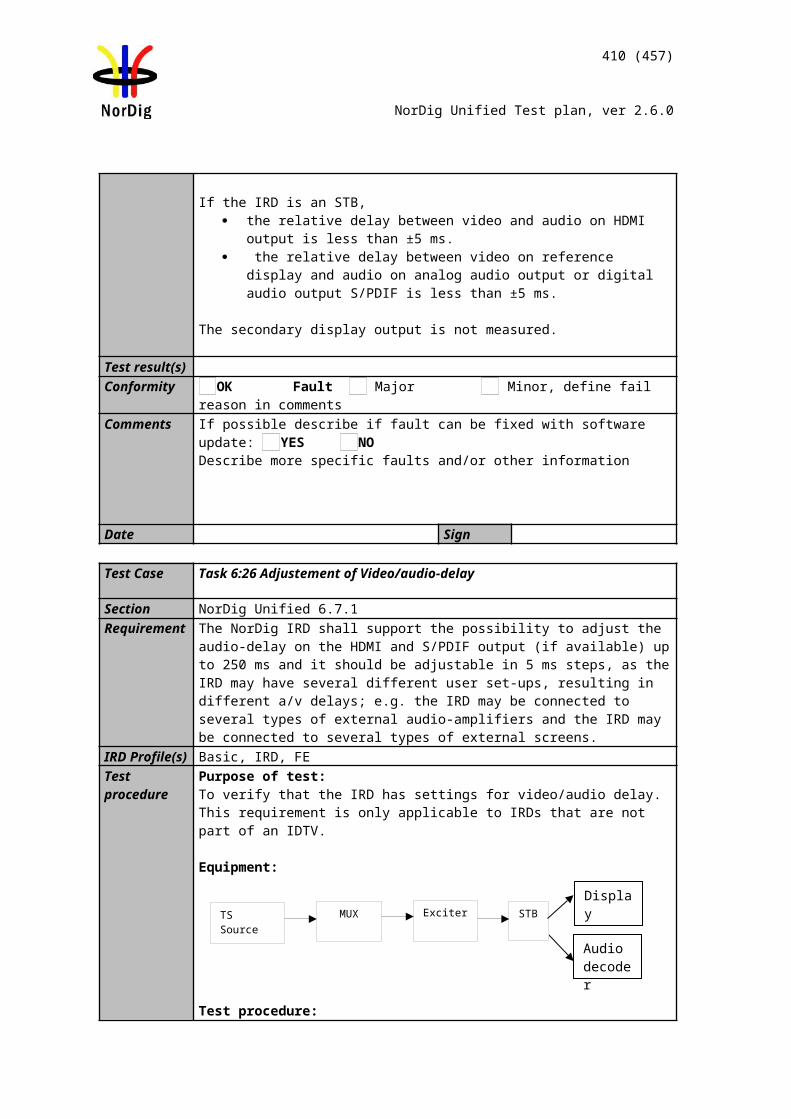
410 (457)
NorDig Unified Test plan, ver 2.6.0
location or several satellite networks are received), one service shall be ordered accord-ing to the logic_channel_number and the others shall be placed last in that list.
Empty spaces in the broadcast logic channel numbering shall then not be used; instead they shall be located last, after the service with highest logic channel number of that ser-vice_type.(The broadcaster may quite consciously choose to leave empty spaces in the logic channel numbering, for future services, etc, in order to avoid a complete rearrange-ment of the list).
Whenever two or more services within same category are allocated to the same logical_channel_number, the HD IRD shall priorities the advanced codec services as following for TV category; first 0x19 adv codec HDTV service, secondly 0x16 adv codec SDTV service and last 0x01 (MPEG-2 SD) TV service and for radio category; first 0x0A adv codec radio and secondly 0x02 radio service types.
Whenever two or more services within same category are allocated to the same logical_channel_number, the NorDig HDTV IRD shall first priorities the advanced codec services as stated in Table12.1 above (see chapter 12.1.4 for priority between dif-ferent services within same service category).
IRD Profile(s) Basic, IRD, FETest procedure
Purpose of test:To verify the support for priority of LCN between SD and HD services.
Equipment:
Service1 Service2 Service3 FrequencyMUX1TS_id 1Network_id 1ON_id 1)
SID 1100S_name Test11S_type 0x01PMT PID 1100V PID 1109A PID 1108LCN Ver.1: 1 visibleLCN Ver.2: 1 visible
SID 1200S_name Test12S_type 0x01PMT PID 1200V PID 1209A PID 1208LCN Ver.1: 2 visibleLCN Ver.2: 2 visible
SID 1300S_name Test13S_type 0x02PMT PID 1300
A PID 1308LCN Ver.1: 3 visibleLCN Ver.2: 3 visible
Can be chosen depending of the distribution media
MUX2TS_id 1Network_id 2ON_id 1)
SID 2100S_name Test21S_type 0x19PMT PID 2100V PID 2109A PID 2108LCN Ver.1: 1 visibleLCN Ver.2: 1 visible
SID 2200S_name Test22S_type 0x16PMT PID 2200V PID 2209A PID 2208LCN Ver.1: 2 visibleLCN Ver.2: 2 visible
SID 2300S_name Test23S_type 0x0APMT PID 2300
A PID 2308LCD ver.1: 3 visibleLCD ver.2: 3 visible
Can be chosen depending of the distribution media, but cannot be same as in MUX1
1) ON_id (Original_network_id) can be chosen in range 0x0001-0xfe00 (operational network) and it shall be same for both muxes.
MUX 1
MUX 2
Exciter 1
Exciter 2Combiner DVB
receiver
TS Source 2
TS Source 1
SI management system
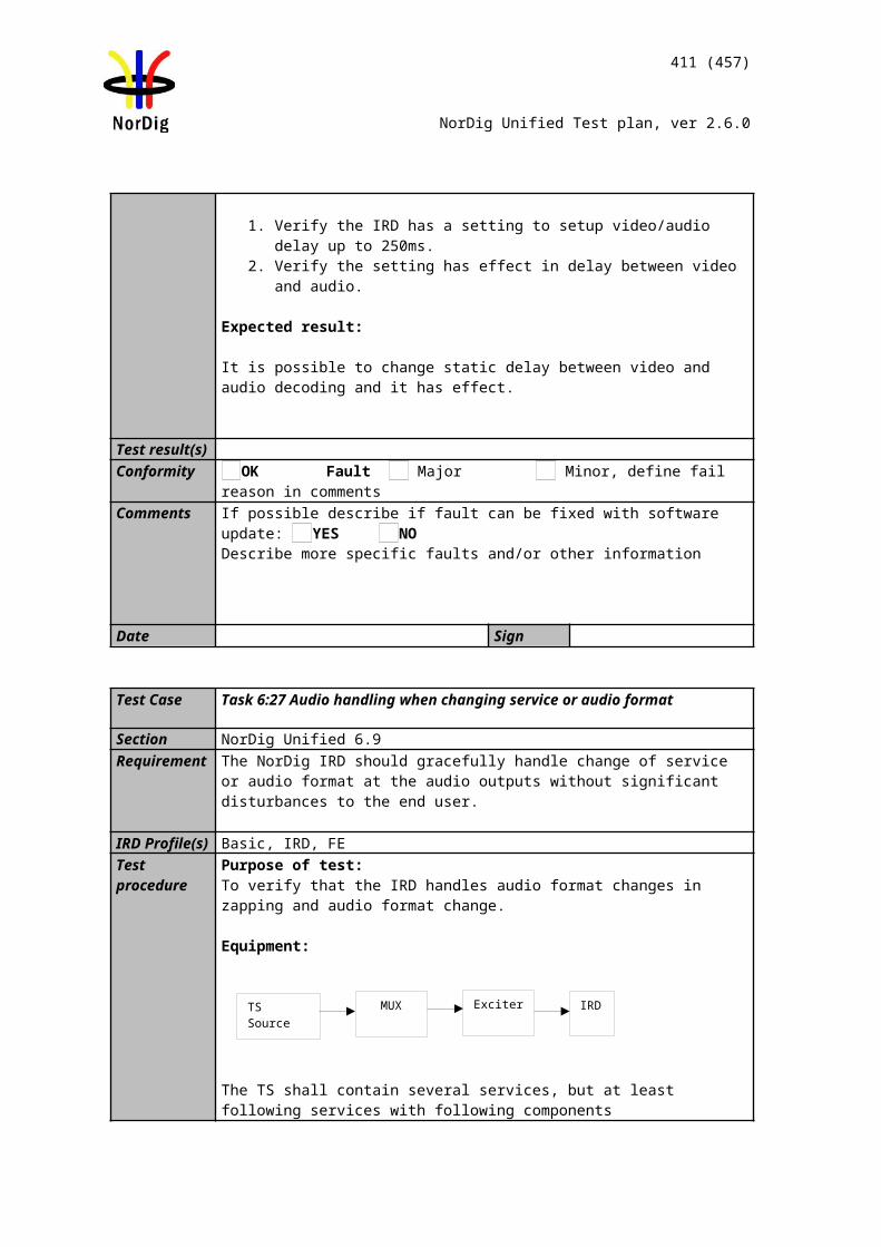
411 (457)
NorDig Unified Test plan, ver 2.6.0
2)Network_id for DVB-C and DVB-S/S2 IRD tests shall be same in all muxes
Note 1: Receiver can use the service_type when sorting the HD and SD services.Note 2: Test13 (HD) has higher priority than Test21 (SD) in HDTV receiver.
Channel list ID is set to 1 with country code equal to receiver country settings.
The TS_id is set to 1, but the network_id differs between multiplexes. This configuration simulates terrestrial regions.
Services in MUX1 are using MPEG-2 video and MPEG-1 LII audio.Services in MUX2 are allowed only use advanced coded video and audio, with other words, MPEG-4 AVC video and HE-AAC or E-AC-3 audio.
The reception quality from both frequencies must be such a good that the terrestrial receiver doesn’t do any best service selection.
Test procedure:
1. Perforn factory reset to the receiver2. Perform channel search3. Verify that the all services are found4. Verify that the services are ordered according the priority
Expected result:The channel numbers are correct.
In SDTV receivers only SDTV services are listed in service list according to their categories.
In HDTV receivers HDTV services are prioritized over SDTV services in correct categories. SDTV services are listed last in the service list.
Services in service list should be stored as in correct categories.
Test result(s) Measurement record:
SDTV receiver with supportPos ‘TV’ ‘Radio’ ‘Data/Other’ NOK or OK1 Test112 Test123 Test13
HDTV receiverPos ‘TV’ ‘Radio’ ‘Data/Other’ NOK or OK1 Test212 Test223 Test23
Last in the list Test11 Test13Last in the list Test12
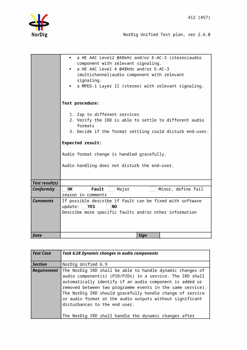
412 (457)
NorDig Unified Test plan, ver 2.6.0
Conformity OK Fault Major Minor, define fail reason in commentsComments If possible describe if fault can be fixed with software update: YES NO
Describe more specific faults and/or other information
Date Sign
2.13.2 Quasi static PSI/SI data
Test Case Task 12:14 Quasi-static update of service list – service addition
Section NorDig Unified 12.1 and 13.2.4Requirement The IRD shall at least start updating for any changes in the received “quasi-static” SI
data, (NIT and SDT i.e. SI that is normally stored in the flash memory for service navigations such as service_name, service_ID, number of services), after it return to active from stand-by mode.
... Initiation of update in the Service List that the IRD is not able to perform in the ‘background’ without disturbances or user action/confirmation, shall (only) be made after manual power up or after user selection to an affected service/transport stream (e.g. when re-scanning is needed).
IRD Profile(s) Basic, IRD, FE
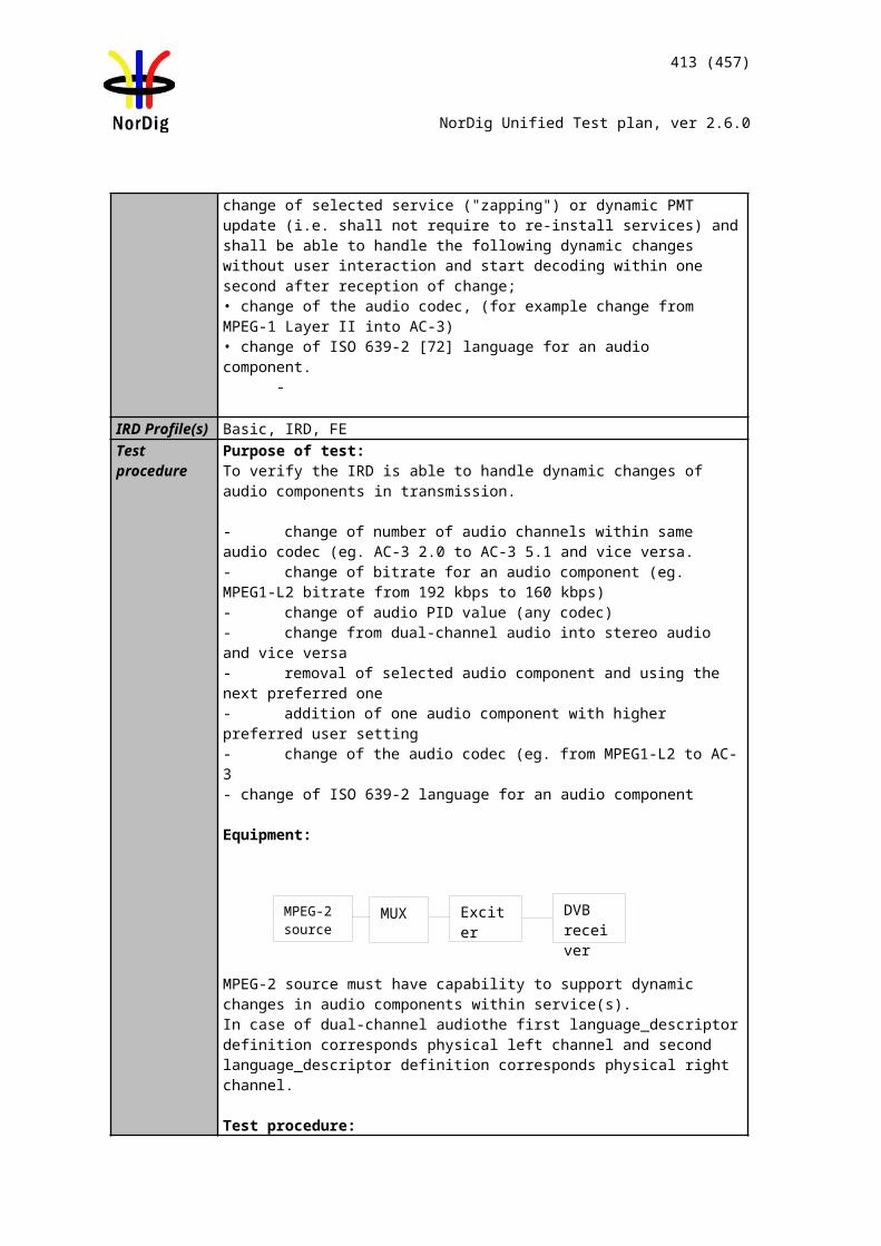
413 (457)
NorDig Unified Test plan, ver 2.6.0
Test procedure Purpose of the test:To check that the IRD updates service list quasi-static when a service is added within transport stream.
Equipment:
NOTE: For the terrestrial networks where several transmitters can be received simultaneously, it is important to verify the parameters original_network_id, transport_stream_id and service_id to make a service unique. In cases where original_network_id and transport_stream_id are the same, but the services carried within transport stream differs, network_id can be interpreted to verify if the transport stream belongs to an other region.
Test procedure:
In initial phase transport stream carries at least one service. In second phase at least one new service is added inclusive the required PSI/SI signalization parameters.
1. Make first time installation of the IRD or verify that the receiver doesn’t have the service which will be added in the service list already installed in the service list..
2. Check that the original service is accessed.3. Add a new service within transport stream
a. Verify the service is added in SDT_actual, PAT and PMT. b. Verify the service is added in service in service_list_descriptor in
NIT_actual 4. Toggle receiver from active mode to standby mode and from standby mode to
active mode5. Verify the added service is added to service list.
Expected result:IRD automatically adds and updates the new service in the service list The service it is accessible.
Test result(s) If possible, mark when the service addition is done: From active mode to stand-by mode From stand-by mode to active mode
In stand-by modeConformity OK Fault Major Minor, define fail reason in commentsComments If possible describe if fault can be fixed with software update: YES NO
Describe more specific faults and/or other information
Date Sign
Test Case Task 12:15 Quasi-static update of service list – non-visible data service addition
Section NorDig Unified 12.1 and 13.2.4Requirement The IRD shall at least start updating for any changes in the received “quasi-static” SI
data, (NIT and SDT i.e. SI that is normally stored in the flash memory for service navigations such as service_name, service_ID, number of services), after it return to active from stand-by mode.
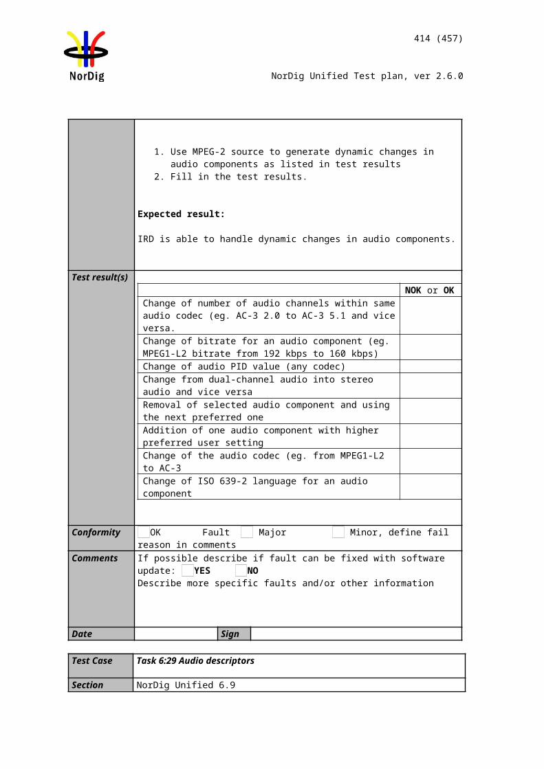
414 (457)
NorDig Unified Test plan, ver 2.6.0
... Initiation of update in the Service List that the IRD is not able to perform in the ‘background’ without disturbances or user action/confirmation, shall (only) be made after manual power up or after user selection to an affected service/transport stream (e.g. when re-scanning is needed).
IRD Profile(s) Basic, IRD, FETest procedure Purpose of test:
To verify that the IRD does not add a “non-visible” data service (Service type 0x0C, LCN: 0 non-visible) in the service list quasi-statically when such a service is added within transport stream.
Equipment:
Service1 Service2 FrequencyMUX1TS_id 1Network_id 1ON_id 1)
SID 1100S_name Test11S type 1PMT PID 1100V PID 1109A PID 1108Logic number 1 visible
SID 1200S_name Test21S type 12PMT PID 1200V PID 1209A PID 1208Logic number 0 non-visible
Can be chosen depending of the distribution media.
1)ON_id (Original_network_id) can be chosen in range 0x0001-0xfe00 (operational network)
Test procedure:
In initial phase transport stream carries at least one service. In second phase at least one new “non-visible” data service is added inclusive the required PSI/SI signalization parameters.
1. Verify that the receiver doesn’t have the service2 in MUX1 already installed.2. Check that the service1 in MUX1 is accessed.3. Add a new “non-visible” data service (Service2 in MUX1) within transport
streama. Verify the service is added in SDT_actual, PAT and PMT. b. Verify the service is added in logical_channel_number_descriptor in
NIT_actual 4. Toggle receiver from active mode to standby mode and from standby mode to
active mode5. Verify that the IRD detects the added service2 in MUX12 without disturbing
end-user and it doesn’t store the service2 in MUX1 in the service list.
2) Receiver can inform end-user with a notice e.g. in case of an own OTA service that a new software is available. In case of unmatched OTA service receiver shall not inform addition of a new service.
Expected result: IRD detects the added “non-visible” data service quasi-statically without end-user disturbance.
The “non-visible” data service is not visible in the service list.
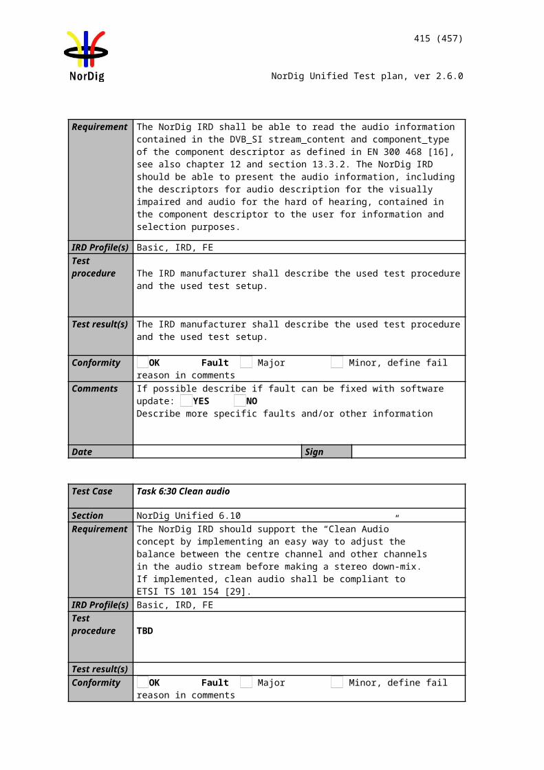
415 (457)
NorDig Unified Test plan, ver 2.6.0
Test result(s)
Conformity OK Fault Major Minor, define fail reason in commentsComments If possible describe if fault can be fixed with software update: YES NO
Describe more specific faults and/or other information
Date Sign
Test Case Task 12:16 Quasi-static update of service list – services moved between different transport streams
Section NorDig Unified 12.1 and 13.2.4Requirement This test is an addition to NorDig Unified TestError: Reference source not found and
Error: Reference source not found.
IRD Profile(s) Basic, IRD, FETest procedure Purpose of test:
To verify that the IRD updates service list quasi-static when one or several services are moved between different transport streams.
Equipment:
Service1 Service2 FrequencyMUX1TS_id 1Network_id 1ON_id 1)
SID 1100S_name Test11S type 1PMT PID 1100V PID 1109A PID 1108Logic number 1 visible
SID 1200S_name Test12S type 1PMT PID 1200V PID 1209A PID 1208Logic number 3 visible
Can be chosen depending of the distribution media.
MUX2TS_id 2Network_id 2ON_id 1)
SID 2100S_name Test21S type 1PMT PID 2100V PID 2109A PID 2108Logic number 2 visible
SID 2200S_name Test22S type 1PMT PID 2200V PID 2209A PID 2208Logic number 4 visible
Can be chosen depending of the distribution media. Not same as for Exciter 1
1) ON_id (Original_network_id) can be chosen in range 0x0001-0xfe00 (operational network) and it shall be same for both muxes
MUX 1
MUX 2
Exciter 1
Exciter 2Combiner STB
TS Source 2
TS Source 1
SI management system
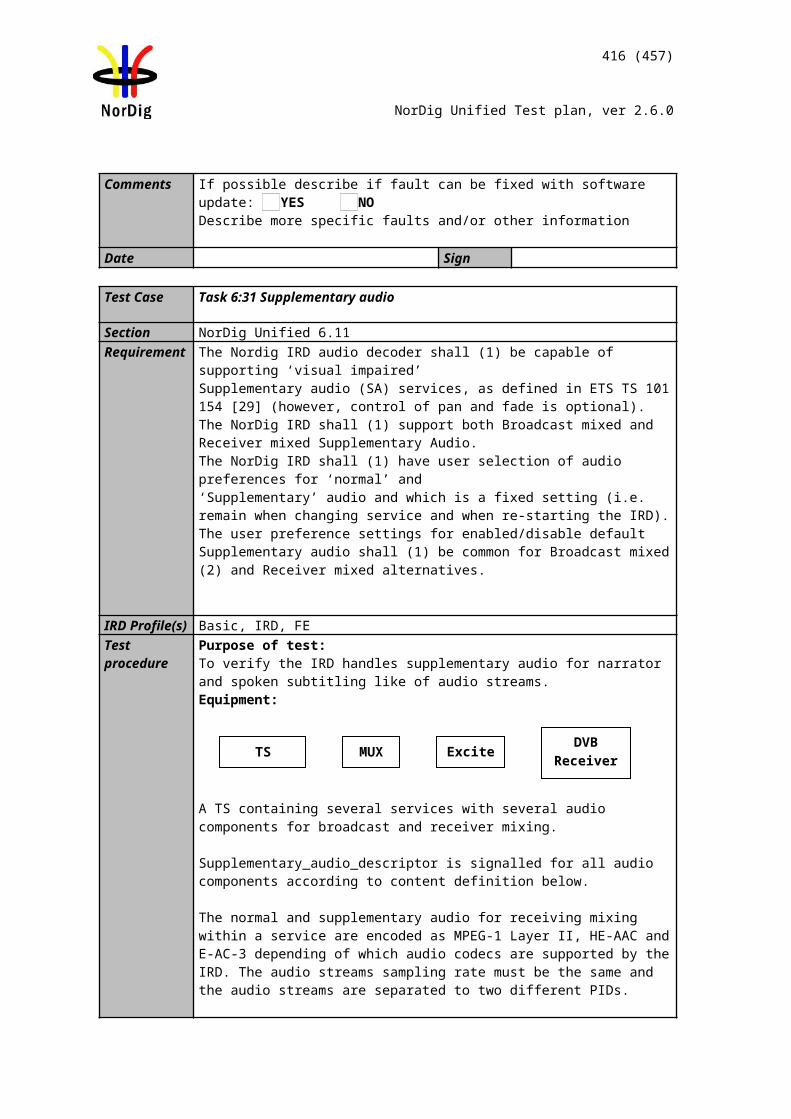
416 (457)
NorDig Unified Test plan, ver 2.6.0
2)Network_id for DVB-C and DVB-S/S2 IRD tests shall be same in all muxes
Test procedure:
1. Verify that the private_data_specifier_descriptor and NorDig_logic_channel_descriptor are signaled in NIT_actual.
2. Perform a re-initialisation and a channel search.3. Verify that the services from MUX 1 and MUX2 are located in service list as
they are signaled.4. Fill in the measurement record 15. Change following configurations:
1. remove service "Test11" from MUX1 and add this service to MUX2, rename it to "Test11 new"
2. remove service "Test21" from MUX2 and add this service to MUX1, rename it to "Test21 new"
6. Toggle between active mode and standby mode.7. Verify the services are stored at their logical numbers in the service list.8. Fill in the measurement record 2.
When a move of service happens, its TS_id and Network_id change according to configuration in this test, the receiver shall identify the service as new and add it in the service list. When the receiver detects the service with equal LCN is removed, it shall move the service from the last positions in service list to its corresponding position signaled in LCN.
Expected result: Services remain at their signaled logical channel positions after moving them between different transport streams.
Test result(s) Measurement record 1:TV list NOK or OK1 Test112 Test213 Test124 Test22
Measurement record 2:TV list NOK or OK1 Test11 new2 Test21 new3 Test124 Test22
Conformity OK Fault Major Minor, define fail reason in commentsComments If possible describe if fault can be fixed with software update: YES NO
Describe more specific faults and/or other information
Date Sign
Test Case Task 12:17 Quasi-static update of service list – service remove
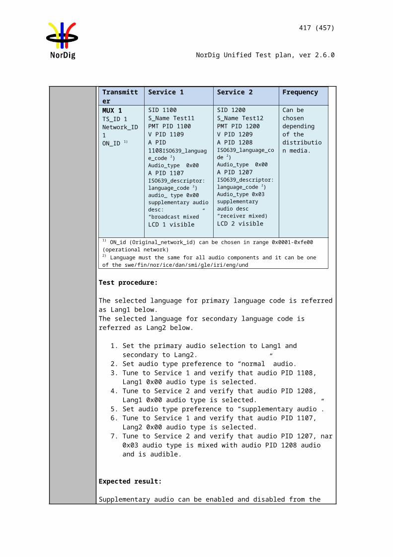
417 (457)
NorDig Unified Test plan, ver 2.6.0
Section NorDig Unified 12.1 and 13.2.4Requirement The IRD shall at least start updating for any changes in the received “quasi-static” SI
data, (NIT and SDT i.e. SI that is normally stored in the flash memory for service navigations such as service_name, service_ID, number of services), after it return to active from stand-by mode.
... Initiation of update in the Service List that the IRD is not able to perform in the ‘background’ without disturbances or user action/confirmation, shall (only) be made after manual power up or after user selection to an affected service/transport stream (e.g. when re-scanning is needed).
IRD Profile(s) Basic, IRD, FETest procedure Purpose of the test:
To check that the IRD updates service list quasi-static when a service is removed within transport stream.
Equipment:
Service1 Service2 FrequencyMUX1TS_id 1Network_id 1ON_id 1)
SID 1100S_name Test11S_type 0x01PMT PID 1100V PID 1109A PID 1108LCN 1 visible
SID 1200S_name Test12S_type 0x01PMT PID 1200V PID 1209A PID 1208LCN 2 visible
Can be chosen depending of the distribution media.
MUX2TS_id 2Network_id 2ON_id 1)
SID 2100S_name Test21S_type 0x01PMT PID 2100V PID 2109A PID 2108LCN 3 visible
SID 2200S_name Test22S_type 0x01PMT PID 2200V PID 2209A PID 2208LCN 4 visible
Bouquet SIAll information in EIT.
Can be chosen depending of the distribution media. Not same as for Exciter 1
1) ON_id (Original_network_id) can be chosen in range 0x0001-0xfe00 (operational network) and it shall be same for both muxes2)Network_id for DVB-C and DVB-S/S2 IRD tests shall be same in all muxes
NOTE: For the terrestrial networks where several transmitters can be received simultaneously, it is important to verify the parameters original_network_id, transport_stream_id and service_id to make a service unique. In cases where original_network_id and transport_stream_id are the same, but the services carried within transport stream differs, network_id can be interpreted to verify if the transport
MUX 1
MUX 2
Exciter 1
Exciter 2Combiner STB
TS Source 2
TS Source 1
SI management system
418 (457)
NorDig Unified Test plan, ver 2.6.0
stream belongs to an other region.
Test procedure:
In initial phase transport stream carries at least two services. In second phase one service is removed inclusive the required PSI/SI signalization parameters.
1. Make first time installation of the IRD or verify that all signaled services within transport stream are in the service list.
2. Remove Service2 carried within transport stream through MUX1a. Verify the Service2 is removed from SDT_actual, PAT and PMT in
MUX1. b. Verify the Service2 is removed from service_list_descriptor in
NIT_actual in MUX1.c. Verify the Service2 is removed from SDT_other in MUX2 in case the
SDT_other is signaled.3. Toggle receiver from active mode to standby mode and from standby mode to
active mode4. Verify the service removed from the service list.
Expected result:IRD automatically removes the service from the service list.
NOTE 1: If the removed service is reserved for any reason, e.g. for timer use, the receiver will have a conflict in that time when the removed service is requested. It is receiver manufacture responsibility to handle such a conflict.
NOTE 2: In that time when the service is removed from the transport stream and user is watching an other service, displaying of any OSD is not allowed, due to the possibility that the viewer may be disturbed of that, e.g. in case of recording another service
NOTE 3: If a user requests a removed service by zapping to that service, an OSD request to remove the service is allowed.
Test result(s) If possible, mark when the service remove is done: From active mode to stand-by mode From stand-by mode to active mode
Does the receiver remove the service from the service list if the user is zapping to a removed service:
Yes No
Conformity OK Fault Major Minor, define fail reason in commentsComments If possible describe if fault can be fixed with software update: YES NO
Describe more specific faults and/or other information
Date Sign
Test Case Task 12:18 Quasi-static update of service list from NIT_actual for non-existing multiplexers
Section NorDig Unified 12.1 and 13.2.4
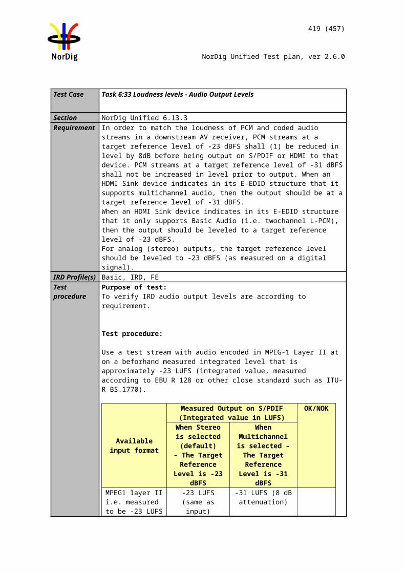
419 (457)
NorDig Unified Test plan, ver 2.6.0
Requirement The IRD shall at least start updating for any changes in the received “quasi-static” SI data, (NIT and SDT i.e. SI that is normally stored in the flash memory for service navigations such as service_name, service_ID, number of services), after it return to active from stand-by mode.
... Initiation of update in the Service List that the IRD is not able to perform in the ‘background’ without disturbances or user action/confirmation, shall (only) be made after manual power up or after user selection to an affected service/transport stream (e.g. when re-scanning is needed).
IRD Profile(s) Basic, IRD, FE
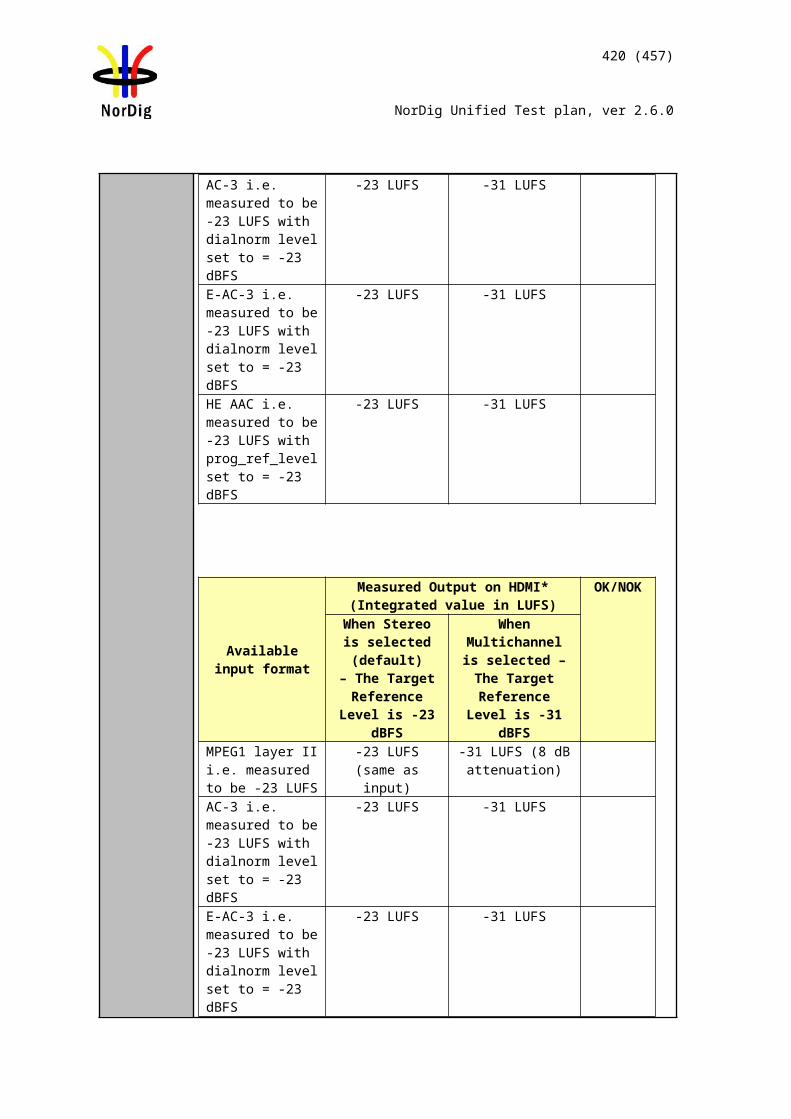
420 (457)
NorDig Unified Test plan, ver 2.6.0
Test procedure Purpose of test:To verify that the IRD is able to update the service list automatically by doing it quasi-statically or dynamically.
Equipment:
NOTE: Assumption in the transport stream NIT_actual is that it has not the TS_id signaled for the added multiplexer.
Test procedure:1. Set up the system and verify the transport stream contains a NIT_actual with
original_network_id in operating range and TS_id=0x1.2. Do a reinstallation of the IRD3. Verify which services IRD has in its service list (and a service from following
steps is not stored in the service list.)4. Turn off the IRD5. Add new TS_id in the NIT_actual including a service_list_descriptor and
logical_channel_descriptor for at least one service. 6. Turn on IRD.7. Verify how (turn on or switch off) the IRD updates the changed data in the
service list. 8. Fill in the test results how the updates are done.9. Verify the IRD at least displays an information message to end-user stating a
new scan is required or do a re-scan in the network.10. Verify that the new service from the new multiplex is added to the service list.
Expected result: IRD shall update the service list by doing a scan in case of the service is in a non-existing multiplex (not scanned before).
Test result(s)Conformity OK Fault Major Minor, define fail reason in commentsComments If possible describe if fault can be fixed with software update: YES NO
Describe more specific faults and/or other information
Date Sign
MUX 1
MUX 2
Exciter 1
Exciter 2Combiner DVB
receiver
TS Source 2
TS Source 1
SI management system
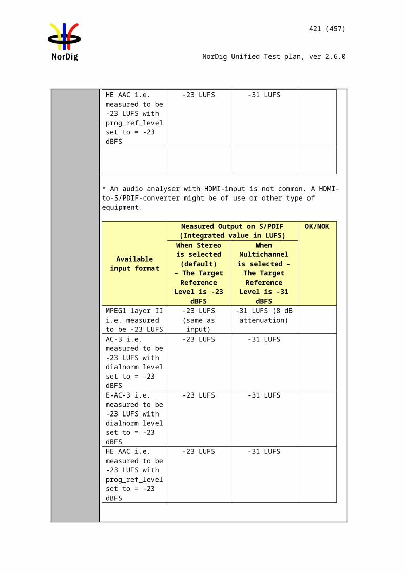
421 (457)
NorDig Unified Test plan, ver 2.6.0
Test Case Task 12:19 Quasi-static update of service list from NIT_actual for removing a multiplex
Section NorDig Unified 12.1 and 13.2.4Requirement The IRD shall at least start updating for any changes in the received “quasi-static” SI
data, (NIT and SDT i.e. SI that is normally stored in the flash memory for service navigations such as service_name, service_ID, number of services), after it return to active from stand-by mode.
... Initiation of update in the Service List that the IRD is not able to perform in the ‘background’ without disturbances or user action/confirmation, shall (only) be made after manual power up or after user selection to an affected service/transport stream (e.g. when re-scanning is needed).
IRD Profile(s) Basic, IRD, FETest procedure Purpose of test:
To verify that the IRD is able to update the service list automatically by doing it quasi-static.
Equipment:
Test procedure:
1. Set up the system and verify that both transport streams contains identical NIT_actual with original_network_id in operating range
2. Do a reinstallation of the IRD3. Verify which services IRD has in its service list (and a service from following
steps is not stored in the service list.)4. Select a channel which is located in TS Source 1.5. Turn off the IRD6. Remove TS Source 2 from the NIT_actual including a service_list_descriptor
and logical_channel_descriptor and switch off RF.7. Turn on IRD.8. Verify how (turn on or switch off) the IRD updates the changed data in the
service list. 9. Fill in the test results how the updates are done.10. Verify the IRD at least displays an information message to end-user stating a
new scan is required or do a re-scan in the network.11. Verify that services from TS Source 2 are removed from channel list.
Expected result: IRD shall update the service list by doing a re-scan.
MUX 1
MUX 2
Exciter 1
Exciter 2Combiner DVB
receiver
TS Source 2
TS Source 1
SI management system
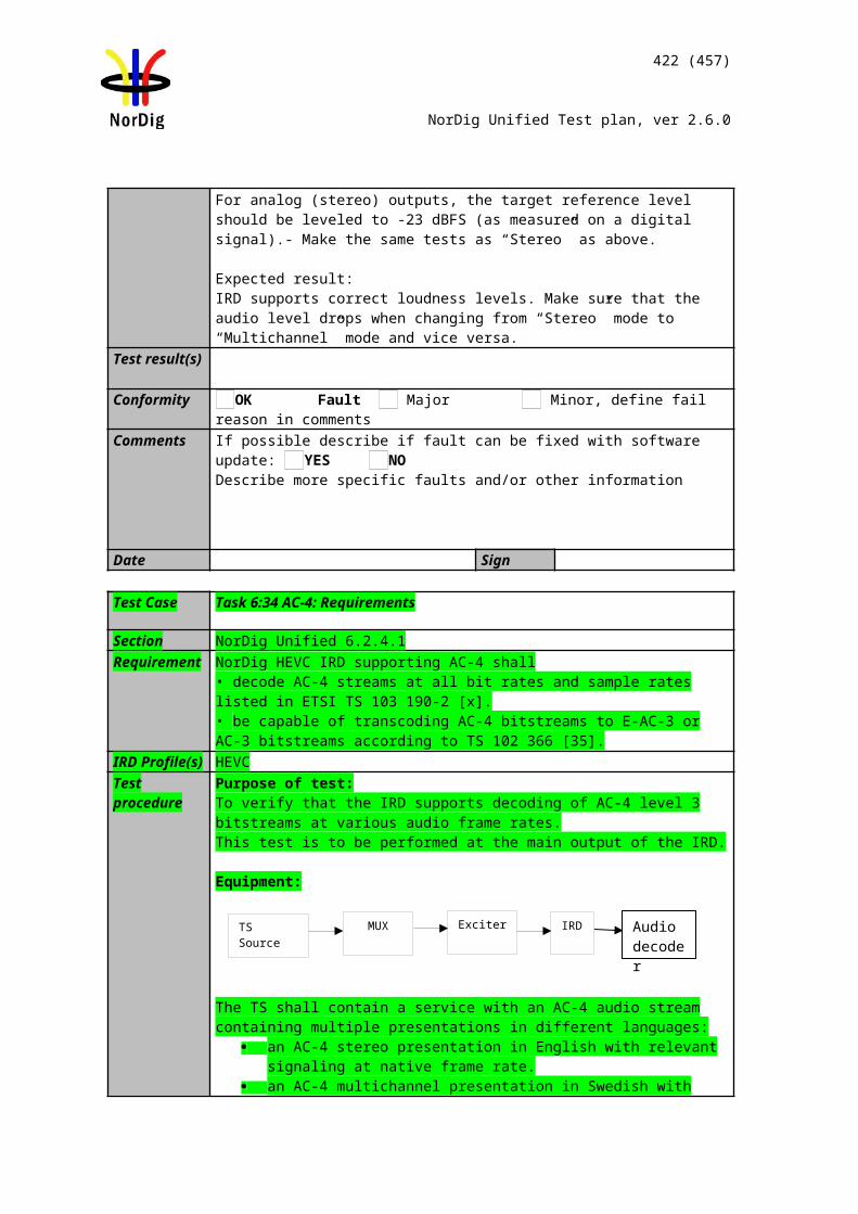
422 (457)
NorDig Unified Test plan, ver 2.6.0
Test result(s)Conformity OK Fault Major Minor, define fail reason in commentsComments If possible describe if fault can be fixed with software update: YES NO
Describe more specific faults and/or other information
Date Sign
Test Case Task 12:20 Quasi-static update of NorDig LCN v1
Section NorDig Unified 12.2.9.1and 13.2.2Requirement NIT descriptors mandatory to receive and interpret if broadcasted:
Private_data_specifier_descriptorNorDig channel descriptor
Services that are not listed in NorDig Logic_channel_descriptor, shall be displayed in the service list(s) and shall be located last in the list (for that service_type).
IRD Profile(s) Basic, IRD, FETest procedure Purpose of test:
To check the support for the private data specifier and NorDig logic channel version 1 descriptors.
To verify that the services, which are not listed in NorDig logic_channel_descriptor are displayed last in service list for that service type.
Equipment:
Service1 Service2 Service3 Service3 FrequencyMUX1TS_id 1Network_id 1ON_id 1)
SID 1100S_name Test11S type 1 or 22PMT PID 1100V PID 1109A PID 1108Logic number 1 visible
SID 1200S_name Test12S type 12PMT PID 1200V PID 1209A PID 1208Logic number 0 non-visible
SID 1300S_name Test13S type 2PMT PID 1300V PID 1309A PID 1308Logic number 3 visible
SID 1400S_name Test14S type 1 or 22PMT PID 1400V PID 1409A PID 1408Logic number 0 non-visible
Can be chosen depending of the distribution media.
SI management system
TS Source 2
TS Source 3
MUX 1
MUX 2
MUX 3
Exciter 1
Exciter 2
Exciter 3
Combiner STB
TS Source 1
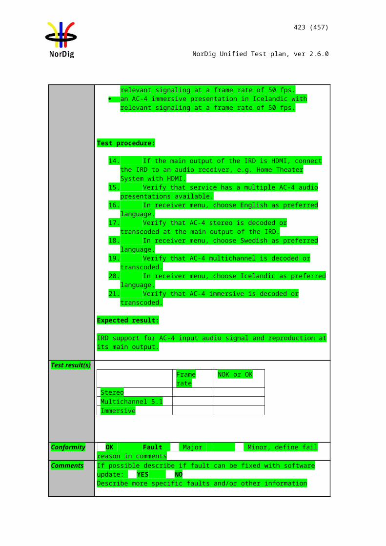
423 (457)
NorDig Unified Test plan, ver 2.6.0
MUX2TS_id 2Network_id 2ON_id 1)
SID 2100S_name Test21S type 1 or 22PMT PID 2100V PID 2109A PID 2108Logic number 3 visible
SID 2200S_name Test22S type 1 or 22PMT PID 2200V PID 2209A PID 2208Logic number missing
SID 2300S_name Test23S type 1 or 22PMT PID 2300V PID 2309A PID 2308Logic number 98 visible
Can be chosen depending of the distribution media. Not same as for Exciter 1
MUX3TS_id 3Network_id 3ON_id 1)
SID 3100S_name Test31S type 1 or 22PMT PID 3100V PID 3109A PID 3108Logic number 2 visible
SID 3200S_name Test32S type 1 or 22PMT PID 3200V PID 3209A PID 3208Logic number 4 visible
SID 3300S_name Test33S type 1 or 22PMT PID 3300V PID 3309A PID 3308Logic number 5 visible
SID 3400S_name Test34S type 1 or 22PMT PID 3400V PID 3409A PID 3408Logic number 10 visible
Can be chosen depending of the distribution media. Not same as for Exciter 1 and 2
1) ON_id (Original_network_id) can be chosen in range 0x0001-0xfe00 (operational network) and it shall be same for all muxes2)Network_id for DVB-C and DVB-S/S2 IRD tests shall be same in all muxes
Test procedure:
1. Verify that the private_data_specifier_descriptor and NorDig_channel_descrip-tor are signaled in NIT_actual.
2. If needed perform a re-initialisation and a channel search. 3. Verify that the services from MUX 1, MUX2 and MUX3 are located in service
list as they are signaled. 4. Fill in the measurement record 15. Verify the service2 in MUX2 is listed last in the TV service list.6. Change the content of the following logical_channel_descriptors
a. service2 in MUX1: from 0 to 1 (visible) b. service4 in MUX1: from 0 to 4 (visible)c. service1 in MUX2: from 3 to 99 (remains visible)d. service2 in MUX3: from 4 to 5 (remains visible)e. service3 in MUX3: from 5 to 0 (non-visible)f. service4 in MUX3: from 10 to 3 (remains visible)
7. Toggle between active mode and standby mode. 8. Verify the services are stored at their logical numbers in the service list.9. Fill in the measurement record 2.
Expected result:Services are stored in correct type of service lists and in their signaled logical channel positions. Service2 in MUX2 is listed last in the TV service list.
Test result(s)Measurement record 1
TV list Radio list Data list NOK or OK1 Test112 Test313 Test214 Test325 Test3310 Test34
3 Test13
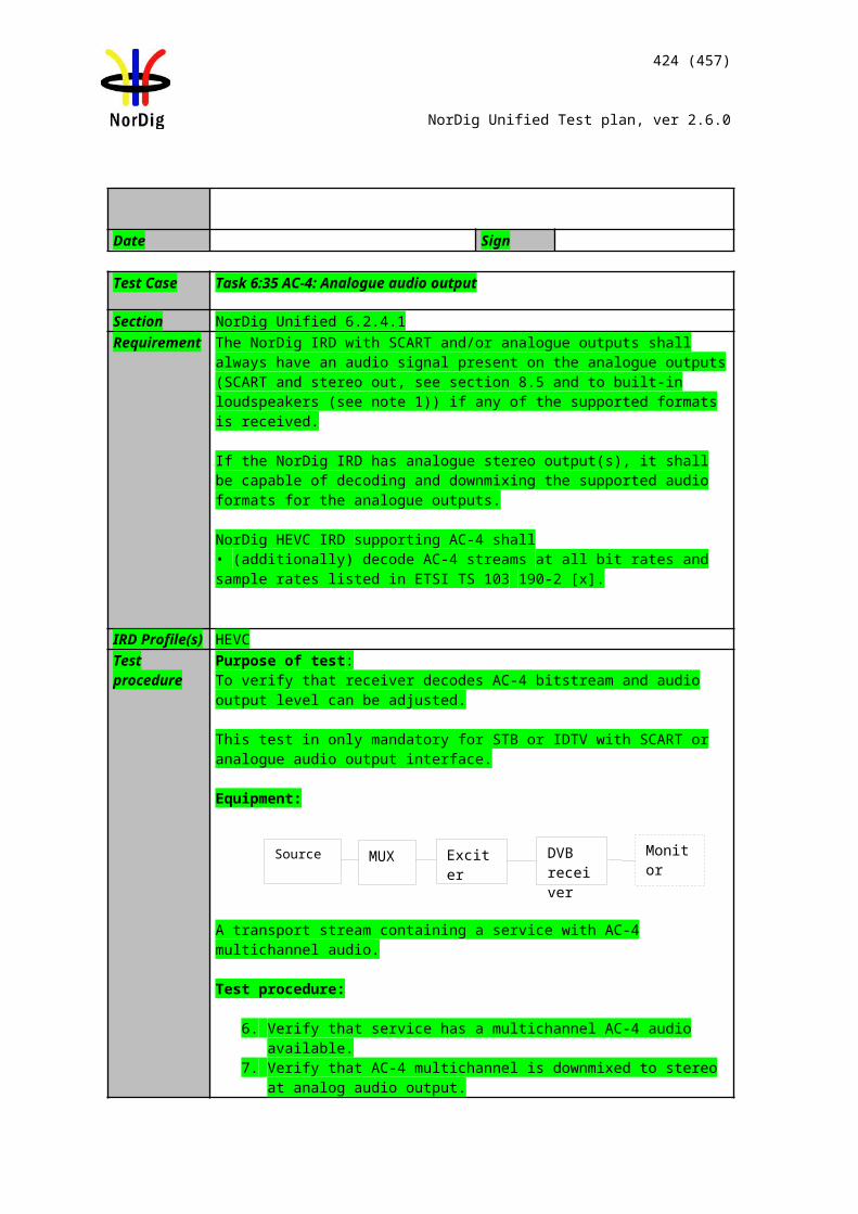
424 (457)
NorDig Unified Test plan, ver 2.6.0
98 Test2399 Test22
Measurement record 2
TV list Radio list Data list NOK or OK1 Test112 Test313 Test344 Test145 Test3298 Test2399 Test21100 Test22
3 Test13 1 Test12
Conformity OK Fault Major Minor, define fail reason in commentsComments If possible describe if fault can be fixed with software update: YES NO
Describe more specific faults and/or other information
Date Sign
Test Case Task 12:21 Quasi-static update of NorDig LCN v2
Section NorDig Unified 12.2.9.2Requirement NIT descriptors mandatory to receive and interpret if broadcasted:
Private_data_specifier_descriptorNorDig logical_channel_descriptor v2
IRD Profile(s) Basic, IRD, FETest procedure Purpose of test:
To check the support for the private data specifier and NorDig logic channel version 2 descriptors.
Equipment:
Service1 Service2 Service3 Frequency
MUX 1
MUX 2
Exciter 1
Exciter 2Combiner STB
TS Source 2
TS Source 1
SI management system
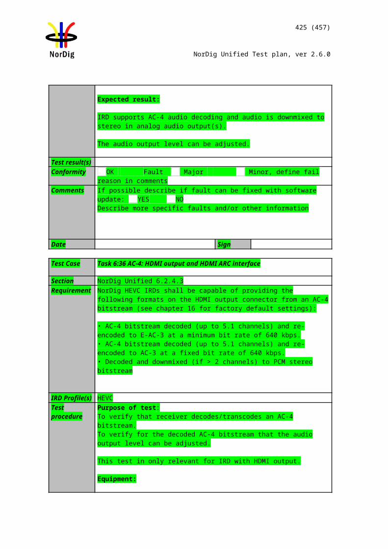
425 (457)
NorDig Unified Test plan, ver 2.6.0
MUX1TS_id 1Network_id 1ON_id 1)
SID 1100S_name Test11S type 1PMT PID 1100V PID 1109A PID 1108LCN Ver.2 1 visible
SID 1200S_name Test12S type 12PMT PID 1200V PID 1209A PID 1208LCN Ver.2 0 non-visible
SID 1300S_name Test13S type 2PMT PID 1300V PID 1309A PID 1308LCN Ver.2 3 visible
Can be chosen depending of the distribution media.
MUX2TS_id 2Network_id 2ON_id 1)
SID 2100S_name Test21S type 1PMT PID 2100V PID 2109A PID 2108LCN Ver.2 3 visible
SID 2200S_name Test22S type 1PMT PID 2200V PID 2209A PID 2208LCN Ver.2 missing
SID 2300S_name Test23S type 1PMT PID 2300V PID 2309A PID 2308LCN Ver.2 98 visible
Can be chosen depending of the distribution media. Not same as for Exciter 1
1) ON_id (Original_network_id) can be chosen in range 0x0001-0xfe00 (operational network) and it shall be same for both muxes2)Network_id for DVB-C and DVB-S/S2 IRD tests shall be same in all muxes
For satellite networks the channel lists represented in tables below are valid due to the capability to receive services within one and same ON_id in different countries where even different country_settings in receiver are relevant. The LCN is equal in all different channel lists IDs.
For cable and terrestrial networks, a subset of channel lists is required as long as one and same ON_id is in concern. Transmissions in these networks are not normally dedicated for receivers with different country settings. Therefore, one channel list is enough to test requirement in this test.
MUX1:Channel_list_ID Channel list name Country_code
1 ListSWE SWE2 ListFIN FIN3 ListNOR NOR4 ListDNK DNK5 ListICE ICE
MUX2:
Channel_list_ID Channel list name Country_code1 ListSWE SWE2 ListFIN FIN3 ListNOR NOR4 ListDNK DNK5 ListICE ICE
Test procedure:
1. Verify that the private_data_specifier_descriptor and NorDig_channel_descrip-tor are signaled in NIT_actual.
2. If needed perform a re-initialisation and a channel search. 3. Verify that the services from MUX 1 and MUX2 are located in service list as
they are signaled. 4. Fill in the measurement record 1
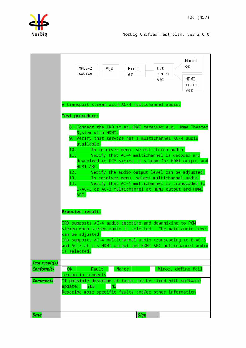
426 (457)
NorDig Unified Test plan, ver 2.6.0
5. Verify the service2 in MUX2 is listed last in the TV service list.6. Change the content of the following logical_channel_descriptors
a. service1 in MUX2: from 3 to 99 (remains visible)b. service2 in MUX1: from 0 to 1 (visible)
7. Toggle between active mode and standby mode. 8. Verify the services are stored at their logical numbers in the service list.9. Fill in the measurement record 2.
Expected result:Services are stored in correct categoriesof service lists, with correct channel list name, and in their signaled logical channel positions. Service2 in MUX2 is listed last in the TV service list. Quasi-static update of service list is performed.
Test result(s)Measurement record 1
Selected country settings in receiver(for information)Selected channel list name (for information)
TV list Radio list Data list NOK or OK1 Test113 Test2198 Test2399 Test22
3 Test13
Measurement record 2
Selected country settings in receiver (for information)Selected channel list name (for information)
TV list Radio list Data list NOK or OK1 Test1198 Test2399 Test21100 Test22
3 Test13 1 Test12
Conformity OK Fault Major Minor, define fail reason in commentsComments If possible describe if fault can be fixed with software update: YES NO
Describe more specific faults and/or other information
Date Sign
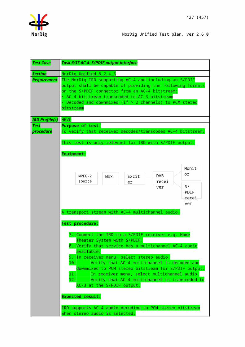
427 (457)
NorDig Unified Test plan, ver 2.6.0
2.14 Task 15: PVR Functionality
Test Case Task 13:1 Recording File System
Section NorDig Unified 14.2Requirement The NorDig PVR shall at all times keep a file system of the PVR’s recordings and make
them available upon request for the user to select and playback.The user shall be able to list the recordings as:
all recordings, as ordered by date&time
For all recordings that have been programmed via the ESG or EPG, each recorded item in the NorDig PVR’s list of recordings shall display for the user at least information about the recorded event’s date of recording and event_name extracted from EIT data during the recording. If no event information is available for a specific recording then the service_name shall be used. For manual recording that span several events, it is recommended to use the service_name instead.
IRD Profile(s) Basic, PVR, IRD, FETest procedure Purpose of test:
To verify that IRD rerodings file system is according requirements
Test procedure:This is a general requirement and will be tested in the following test tasks.
Test Case Task 13:2 Recording capacity
Section NorDig Unified 14.2.2Requirement The NorDig PVR shall be able to indicate its momentary available recording capacity.
The basis for the indication shall be explained in the instruction manual and should be in terms of capacity (e.g. GB), percentage or time (e.g. hours).
The Manufacture shall clearly state the recording capacity for the NorDig PVR in marketing specification and in the instruction manual. It shall as a minimum be specified in terms of bytes (like GigaByte, GB etc).
IRD Profile(s) Basic, PVR, IRD, FETest procedure Purpose of test:
To verify that IRD indicates the capacity of the mass storage.
Equipment:IRD Under test
Test procedure:1. Verify that the recording capacity is presented in the IRD menu.2. Verify that the instruction manual states clearly the recording capacity.
Expected results:The IRD and the instruction manual indicates the recording capacity.
Test result(s)Conformity OK Fault Major Minor, define fail reason in comments
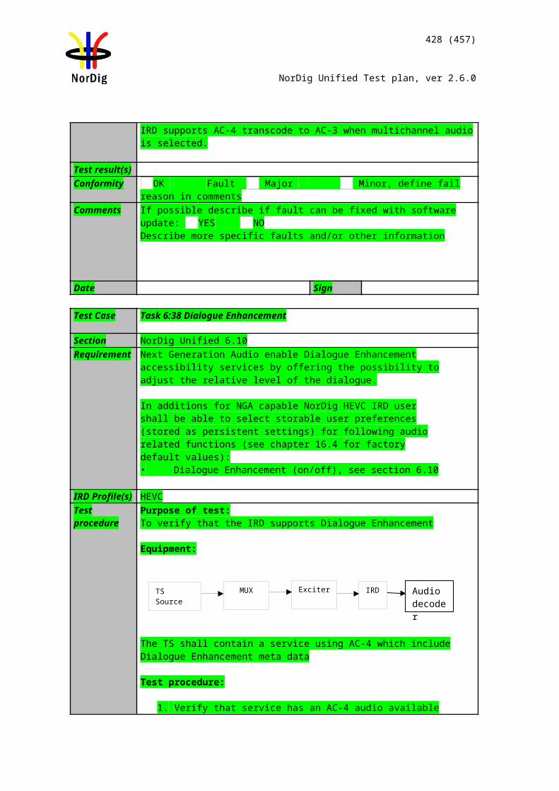
428 (457)
NorDig Unified Test plan, ver 2.6.0
Comments If possible describe if fault can be fixed with software update: YES NODescribe more specific faults and/or other information
Date Sign
Test Case Task 13:3 Deletion of the recordings
Section NorDig Unified 14.2.3Requirement The user shall be able to manually delete any recorded event in the NorDig PVR by de-
leting one recording at the time.
The NorDig PVR shall have a mode (set as factory default) where the NorDig PVR shall ask for user confirmation before deletion of recordings (i.e. the NorDig PVR may in ad-dition have alternative mode where the NorDig PVR will delete recordings without any extra confirmation).
IRD Profile(s) Basic, PVR, IRD, FETest procedure Purpose of test:
To verify that receiver that the IRD can delete PVR content.
Test Equipment:
Test procedure:
1. Open the Receivers PVR/PDR content menu.2. Select one recorded program and delete it.3. Verify that the content is removed and PVR/PDR storage is freed.4. Verify that the IRD has a function that removes all recordings from the mass
storage.
Expected results:The receiver shall handle deletion of the recorded content.
Test result(s)Conformity OK Fault Major Minor, define fail reason in commentsComments If possible describe if fault can be fixed with software update: YES NO
Describe more specific faults and/or other information
Date Sign
Test Case Task 13:4 Failed and incomplete recordings
Section NorDig Unified 14.2.4Requirement The NorDig PVR shall have a mechanism for informing the user of failed or incomplete
(partial) recordings. For incomplete (partial) recordings it should inform the user how much of the booked event has not been successfully recorded.
IRD Profile(s) Basic, PVR, IRD, FE
429 (457)
NorDig Unified Test plan, ver 2.6.0
Test procedure Purpose of test:To verify that IRD handles the failded and incomplete recordings according requirements.
Equipment:IRD Under test
Test procedure:
1. Schedule a recording.2. Disconnect IRD from mains before the start time of the recording.3. Re-connect IRD to mains after the end time of the recording.4. Verify that the IRD indicates the recording has failed.
Incomplete recordings will be tested in test cases below.
Test result(s)Conformity OK Fault Major Minor, define fail reason in commentsComments If possible describe if fault can be fixed with software update: YES NO
Describe more specific faults and/or other information
Date Sign
Task 13:5 File system intact after update
Section NorDig Unified 14.2.6Requirement The NorDig PVR’s file systems of recorded events shall be intact after
• updating of the PVR IRD’s System Software and/or• updating of CA system and/or• re-installation or update of installed services
IRD Profile(s) Basic, PVR, IRD, FETest procedure Purpose of test:
To verify that IRD file system is intact after system update, CA system update and/or re-istallation or update of the installed services
Equipment: IRD Under test Test stream
Preparation for the test:1. Perform recordings to the IRD mass media.2. View some of the recordings.3. List the content on the mass media.
Test procedure:1. Perform a SW update (for example, during SSU update test tasks).2. Verify that all expected recordings on the IRD mass media are available after
the SW update.3. Perform a CA system update:
a. IRD with Common Interface: Change the CA module to another.b. IRD with integrated CA system: Manufacturer describe the procedure
4. Verify that all expected recordings on the IRD mass media are available after the CA system update.
5. Perform factory reset and new installation of the IRD6. Verify that all expected recordings on the IRD mass media are available after
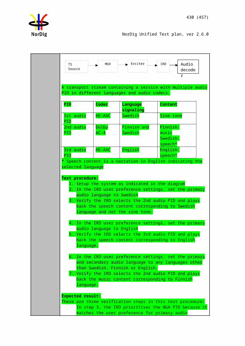
430 (457)
NorDig Unified Test plan, ver 2.6.0
the new installation.
Expected result:The file system is intact after a software update.
Test result(s) Measurement recordTest point Result OK/NOKRecordings are available after SW updateRecordings are available after CA system updateRecordings are available after IRD re-installation
Conformity OK Fault Major Minor, define fail reason in commentsComments If possible describe if fault can be fixed with software update: YES NO
Describe more specific faults and/or other information
Date Sign
Task 13:6 Limitations in recorded content – no extraction
Section NorDig Unified 14.2.7Requirement For protected content (unless otherwise specified by the relevant network/Operator), it
shall not be possible to extract or output content from the NorDig PVR in un-protected format, therefore all recordings shall be stored in a protected format not easy to extract by the user.
IRD Profile(s) Basic, PVR, IRD, FETest procedure Purpose of test:
To verify that IRD’s recorded content is not extratable to the user
Equipment:IRD Under test
Test procedure:1. Make sure that IRD has some recorded content2. Verify that the content is not extractable in un-protected format
Expected results:The IRD shall protect the content on mass storage
Test result(s)Conformity OK Fault Major Minor, define fail reason in commentsComments If possible describe if fault can be fixed with software update: YES NO
Describe more specific faults and/or other information
Date Sign
Task 13:7 Limitations in recorded content – downscaling of the HD content to the removable media
Section NorDig Unified 14.2.7
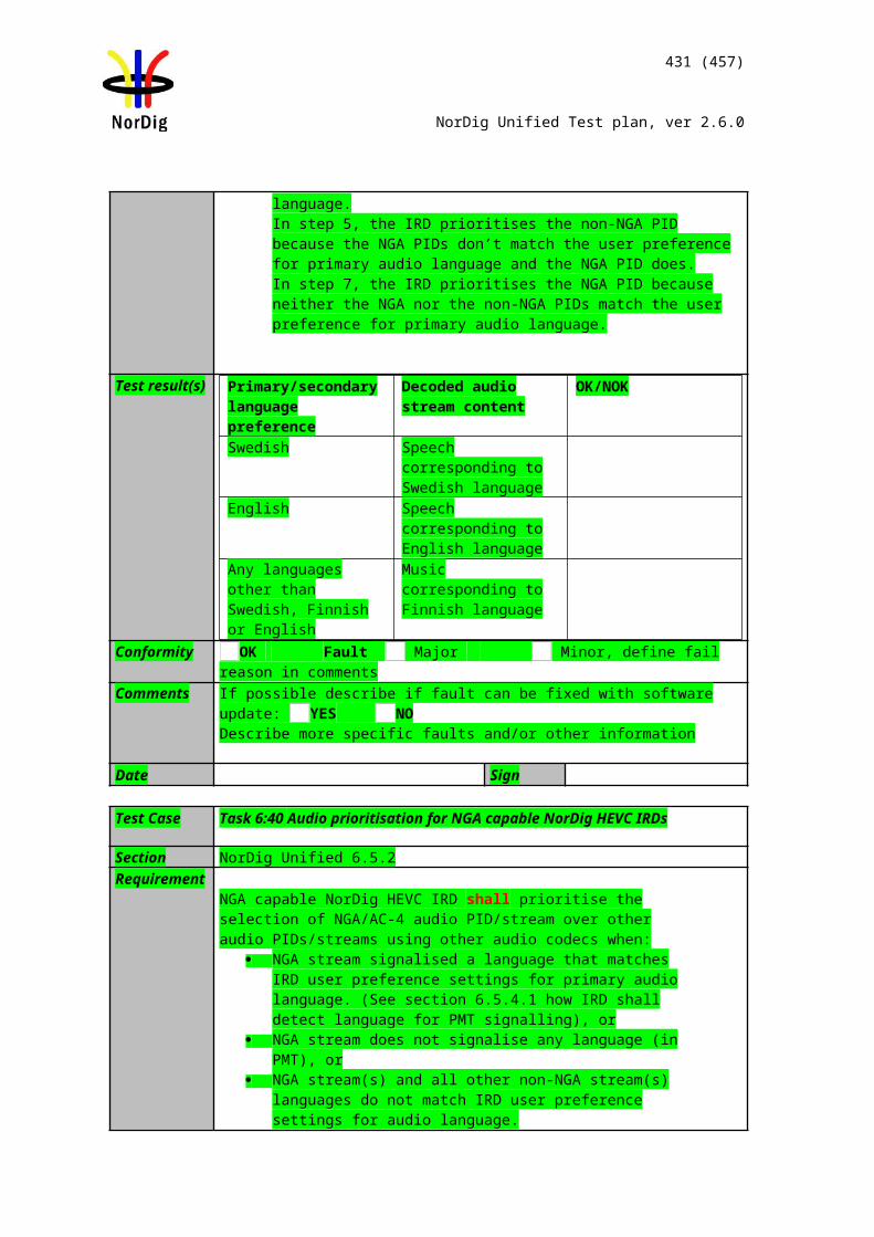
431 (457)
NorDig Unified Test plan, ver 2.6.0
Requirement NorDig PVRs’ using standardised removable media, such as DVD or Blu-ray for recording of protected content shall downscale any HD content to SD resolution (maximum 720x576) before storing it to the removable media. HD content may be recorded in its original resolution if the recording retains the original broadcast scrambling or any other local device scrambling approved by the Network/Operator.
IRD Profile(s) Basic, PVR, IRD, FETest procedure Purpose of test:
To verify that IRD’s recorded content is downscaled to standardized removable media.
Equipment:IRD Under test
This test is applicable only for NorDig PVR IRDs that are able to store the content to a standardized removable media, such as DVD or Blu-ray disc.
Test procedure:1. Record HD content to a standardized media.2. Verify that the content is recorded as downscaled to SD format.
Expected results:The IRD shall downscale the content on removable media.
Test result(s)Conformity OK Fault Major Minor, define fail reason in commentsComments If possible describe if fault can be fixed with software update: YES NO
Describe more specific faults and/or other information
Date Sign
Task 13:8 Disk Management
Section NorDig Unified 14.2.8Requirement The NorDig PVR shall have appropriate disk management (including de-fragementation
handling for Hard Disk Drive based PVRs) to minimise need for re-formatting disk during its lifetime.
IRD Profile(s) Basic, PVR, IRD, FETest procedure Purpose of test:
To verify that IRD has the disk management function
Equipment:IRD Under test
Test procedure:1. Verify that the IRD has the disk management and de-fragmentation function
Expected results:The IRD has the disk management function.
Test result(s)Conformity OK Fault Major Minor, define fail reason in commentsComments If possible describe if fault can be fixed with software update: YES NO
Describe more specific faults and/or other information
Date Sign
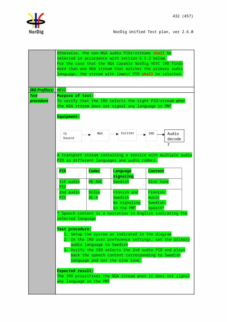
432 (457)
NorDig Unified Test plan, ver 2.6.0
Task 13:9 General PVR recording – bitrates
Section NorDig Unified 14.3.1Requirement The NorDig PVR shall as a minimum support recording up to 20 Mbps per (SD) service
and shall as a minimum support recording up to 30 Mbps per (HD) service. The NorDig PVR shall be able to record for at least 60 minutes with the above transmission figures.
IRD Profile(s) Basic, PVR, IRD, FETest procedure Purpose of test:
To verify that IRD meet with the general requirements
Equipment:
Test stream with SD service of 20 Mbps bit rateTest stream with HD service of 30 Mbps bit rate
Test procedure:1. Select a SD service with 20 Mbps bit rate.2. Start recording for duration of one hour.3. Select a HD service with 30 Mbps bit rate.4. Start recording for duration of one hour.5. Verify that the recordings are performed correctly.
Expected results:The IRD is cabable of recording with the required service bitrate.
Test result(s) Measurement recordTest point Result OK/NOKSD content, bitrate up to 20Mbps can be recorded and viewedHD content, bitrate up to 30Mbps can be recorded and viewed
Conformity OK Fault Major Minor, define fail reason in commentsComments If possible describe if fault can be fixed with software update: YES NO
Describe more specific faults and/or other information
Date Sign
Task 13:10 General PVR recording – service types
Section NorDig Unified 14.3.1 and 14.3.9Requirement The NorDig PVR shall be able to record all supported service types (TV, radio etc) and
its components (as described in NorDig Unified 14.3.9)IRD Profile(s) Basic, PVR, IRD, FETest procedure Purpose of test:
To verify that IRD record and plays all service types and the components in the service
Equipment:
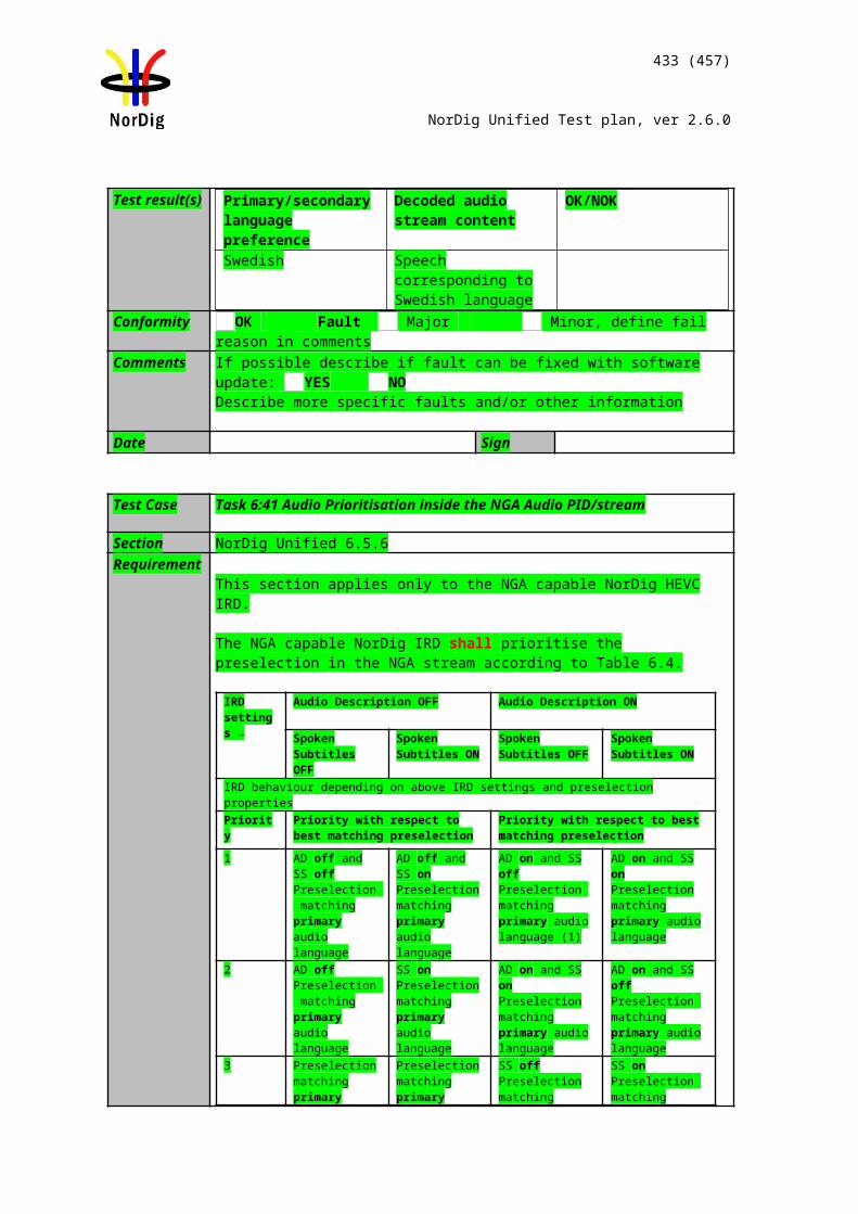
433 (457)
NorDig Unified Test plan, ver 2.6.0
Service1 Service2 Service3 FrequencyMUX1 TS_id 1Network_id 1ON_id 1)
SID 1100Service type 0x01S_name Test11PMT PID 1100V PID 1109A PID 1108LCD: 1 visibleEncrypted
SID 1200Service type 0x02S_name Test12PMT PID 1200
A PID 1208LCD: 2 visibleClear
SID 1300Service type 0x0CS_name Test13PMT PID 1300V PID 1309A PID 1308LCD: 3 visibleClear
Can be chosen depending of the distribution media
MUX2 TS_id 2Network_id 22)
ON_id 1
SID 2100Service type 0x16S_name Test21PMT PID 2100V PID 2109A PID 2108LCD: 4 visibleClear
SID 2200Service type 0x19S_name Test22PMT PID 2200V PID 2209A PID 2208LCD: 5 visibleClear
SID 2300Service type 0x0AS_name Test23PMT PID 2300
A PID 2308LCD: 6 visibleClear
Can be chosen depending of the distribution media
1) ON_id (Original_network_id) can be chosen in range 0x0001-0xfe00 (operational network) and it shall be same for both muxes and it shall be same for both muxes2)Network_id for DVB-C and DVB-S/S2 IRD tests shall be same in all muxes
Channel list ID is set to 1 and country_code according to country settings in the receiver. Services in MUX1 are using MPEG-2 video and MPEG1 LII audio.Services in MUX2 are allowed only use advanced coded video and audio, with other words MPEG-4 AVC video and HE-AAC or E-AC-3 audio.Services may contain multiple audio and subtitling tracks and teletext.
Test procedure:
1. Perform factory reset and new installation of the IRD.2. Verify the IRD installs the channels to appropriate service lists.3. Perform a recording, e.g.5 min, on each service.4. Play back the recordings.5. Verify that the IRD plays back the recordings correctly and all components are
available in the recording.
Expected results:The IRD records and plays the complete service.
Test result(s) Service name
Service type Result OK/NOK
Test11 Digital television service (0x01)
MUX 1
MUX 2
Exciter 1
Exciter 2Combiner STB
TS Source 2
TS Source 1
SI management system
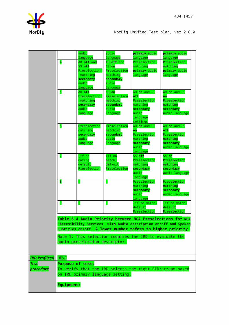
434 (457)
NorDig Unified Test plan, ver 2.6.0
Test12 Digital radio sound service (0x02)Test13 Data broadcast service (0x0C)Test21 H.264/AVC SD digital television service (0x16)Test22 H.264/AVC SD digital television service (0x19)Test23 Advanced codec digital radio sound service (0x0A)
Conformity OK Fault Major Minor, define fail reason in commentsComments If possible describe if fault can be fixed with software update: YES NO
Describe more specific faults and/or other information
Date Sign
Task 13:11 ESG/EPG recording programming – individual events without CRID
Section NorDig Unified 14.3.2Requirement The NorDig PVR shall make it possible for the user to select individual events and
series to be recorded from the ESG or EPG display (based on information from EIT data).
IRD Profile(s) Basic, PVR, IRD, FETest procedure Purpose of test:
To verify that the IRD is able to handle several scheduled recordings (manual and EPG scheduled) in on mode.To verify that the IRD is able to wake up from standby to perform scheduled recordings and set itself back into the originating power state after the scheduled recordings have been completed.
Equipment:
Live network or a test network of 3 MUX (tbd) is used for this test.
ESG schedule events as follows:
Test procedure:1. Schedule several events from ESG/EPG for recording as follows:
a. Events with a long time gap (> 10 min) between the eventsb. Events with a short time gap (≤ 10 min) between the events
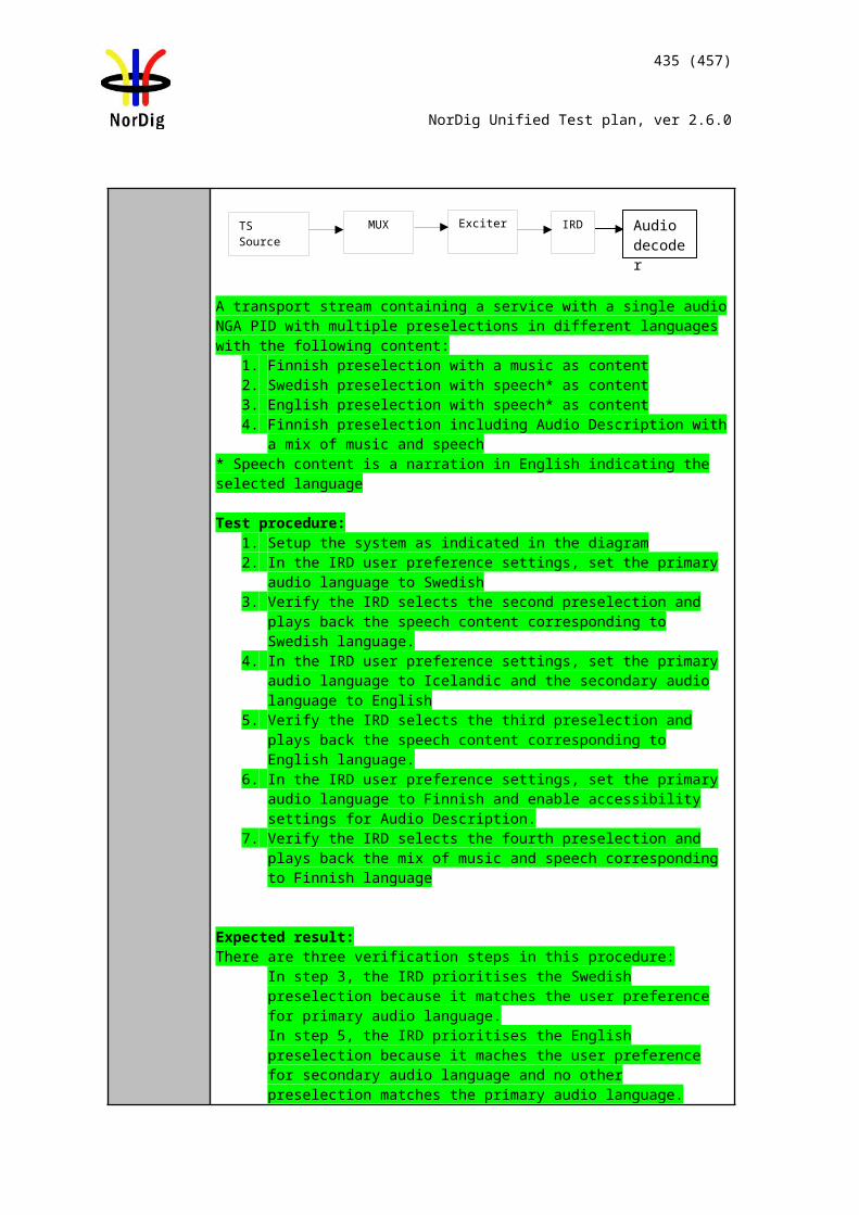
435 (457)
NorDig Unified Test plan, ver 2.6.0
2. Take note on/list the scheduled events (event name, start time, duration, service).3. Select a service on MUX3.4. Set the IRD to stand-by mode.5. Verify that the IRD records all the scheduled events and returns back to the
originating power state after each scheduled event. 6. Resume the IRD from standby.7. Verify that all the scheduled events are recorded and they can be played back
correctly.
Expected results:
The IRD performs scheduled recordings correctly in all possible situations.
The IRD sets itself back to the originating power state after recording.
Test result(s) Measurement recordTest point Result OK/NOKIRD records individual events with a long gap in betweenIRD records individual events with a short gap in between
Conformity OK Fault Major Minor, define fail reason in commentsComments If possible describe if fault can be fixed with software update: YES NO
Describe more specific faults and/or other information
Date Sign
Task 13:12 ESG/EPG recording programming – individual event with CRID
Section NorDig Unified 14.3.2Requirement The NorDig PVR shall make it possible for the user to select individual events and
series to be recorded from the ESG or EPG display (based on information from EIT data).
IRD Profile(s) Basic, PVR, IRD, FETest procedure Purpose of test:
To verify that IRD enables ESG/EPG reording programming for individual event.
Equipment:IRD Under testStream
Test procedure:1. Open the EPG and schedule a recording by selecting an event with CRID in the
EPG.2. Verify that the IRD records the event correctly.3. Playback recording initiated by EPG.
Expected results:The IRD enables recording from EPG/ESG.
Test result(s)Conformity OK Fault Major Minor, define fail reason in comments
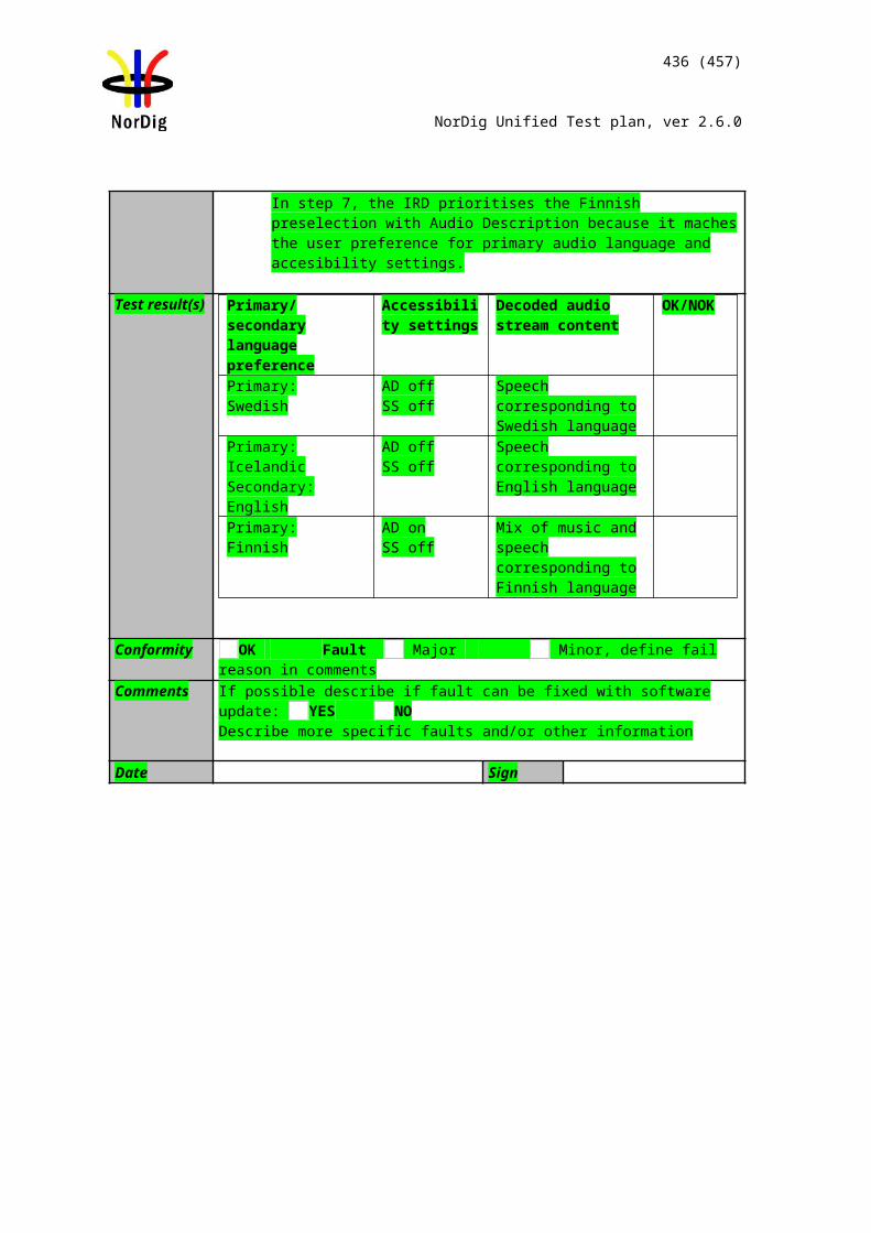
436 (457)
NorDig Unified Test plan, ver 2.6.0
Comments If possible describe if fault can be fixed with software update: YES NODescribe more specific faults and/or other information
Date Sign
Task 13:13 ESG/EPG recording programming – individual event with CRID – same event recording
Section NorDig Unified 14.3.2Requirement If the user selects an event for recording from the ESG/EPG which has the same
programme CRID value as an earlier recording within the NorDig PVR list of recordings, the NorDig PVR shall inform the user at the time of booking that this new selected event might already have been recorded and offer the option for the user to record anyway or not (1). The NorDig PVR should display information about this earlier recording (like the event name, date of recording and description).
IRD Profile(s) Basic, PVR, IRD, FETest procedure Purpose of test:
To verify that IRD informs user if ESG/EPG reording programming for individual event is already set for recording.
Equipment:IRD Under testStream with EIT including CRID. Two events shall have the same CRID value.
Test procedure:1. Open the EPG and schedule a recording by selecting an event with CRID in the
EPG.2. Try schedule another later recording from the ESG/EPG by selecting an event with
the same CRID in the EPG that has been already selected for recording.3. Verify that the IRD informs the user that the event is already set for recording.
Expected results:The IRD inform user if the same program with same CRID is already selected for recording from the EPG/ESG.
Test result(s)Conformity OK Fault Major Minor, define fail reason in commentsComments If possible describe if fault can be fixed with software update: YES NO
Describe more specific faults and/or other information
Date Sign
Task 13:14 ESG/EPG recording programming – series
Section NorDig Unified 14.3.3Requirement All events that have the same series CRID belongs to the same Series. An individual
event inside a Series is referenced here as an Episode. (For definition of CRID see section 12.4.6.2).
The NorDig PVR shall be able to record a complete Series via the CRID.The NorDig PVR shall store and track series CRIDs that are programmed for recording for up to 91 days between occurrences in EIT schedule. To allow broadcasters to reuse a series CRID for a different editorial concept, the NorDig PVR shall discard any series
437 (457)
NorDig Unified Test plan, ver 2.6.0
CRIDs not seen in EIT for 91 days.
The display of programmes selected for recording shall include an indication if the programme is included as a consequence of being one of a series.
The IRD should be aware that the default authority may be changed over time (for example a service might have default authority added in SDT), the NorDig PVR should automatically update its stored default authorities (not only during installation).
The NorDig PVR shall support recording of all episodes of a specific series via series CRID’ws in the broadcast.It shall be possible from ESG/EPG to program the NorDig PVR to record a series of events. The NorDig PVR shall indicate in the ESG/EPG that an event is part of a series (1). The NorDig PVR shall, if the user selects to record the event that belongs to a series, request the user what to record:
1. Only the single event selected.2. Several or All events (episodes) of the series
IRD Profile(s) Basic, PVR, IRD, FETest procedure Purpose of test:
To verify that IRD enables ESG/EPG reording programming for series of events.
Equipment:IRD Under testStream with EIT information including CRID.
Test procedure:1. Open the EPG and schedule a recording by selecting a series CRID in the EPG.2. Verify that EPG contains information that event is part of the Series3. Initiate recording4. Verify that IRD is asking if one or all Episodes shall be recorded5. Select all Episodes6. Verify that all Episodes of the Series is recorded7. Playback all recordings initiated by EPG and verify that recordings are playbacked
correctly
8. Open the EPG and schedule a recording by selecting a series CRID in the EPG.9. Verify that EPG contains information that event is part of the Series10. Initiate recording11. Verify that IRD is asking if one or all Episodes shall be recorded12. Select all one Episode13. Verify that only one Episode of the Series is recorded14. Playback recording initiated by EPG and verify that recording is playbacked
correctly
Expected results:The IRD enables series recording from EPG/ESG.
Test result(s)Conformity OK Fault Major Minor, define fail reason in commentsComments If possible describe if fault can be fixed with software update: YES NO
Describe more specific faults and/or other information
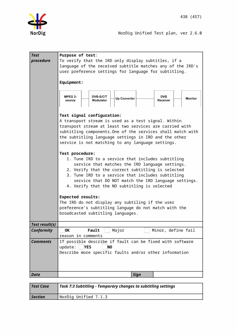
438 (457)
NorDig Unified Test plan, ver 2.6.0
Date Sign
Task 13:15 Split recordings
Section NorDig Unified 14.3.4Requirement A programme may consist of multiple EIT events within the same service or over
several services. For example, a film might be divided into two parts/blocks interrupted by a news programme in the middle (see Figure 14.1 A) or a longer sport event might be split into several parts/blocks over several services, (see Figure 14.1 B).
Signalling carried in the SI allows the PVR to identify and record all the events containing the parts of a single programme. A “split programme” is a single piece of content which comprises of two or more EIT events having the same CRID and IMI value with the gap from the scheduled end time (start_time plus duration) to the scheduled start time of any two of those events is less than 3 hours (see section12.4.6).
The NorDig PVR shall consider a split programme to be segments of a single item of content (1). When selecting a split programme for recording, the NorDig PVR shall select and record all constituent events so that the complete programme content is recorded.
There are cases where a NorDig PVR may during the time of programming a recording only see a single event with the booked CRID and IMI combination (for example initially only the first part/block of the split programme has so far been included in the EIT).
The NorDig PVR shall continue to monitor the EIT for additional events with the same CRID and IMI combination and include them to the selected recording (1). In case of overlap between the split events and if the NorDig PVR has limitation in recording capacity when back-to-back recording, then the NorDig PVR shall first finalise recording of the first part/event of the split programme (according to the events start time and duration) before starting recording the next part of the split programme, This is the same behaviour as back-to-back recordings.
IRD Profile(s) Basic, PVR, IRD, FETest procedure Purpose of test:
To verify that IRD handles split recordings.
Equipment: IRD Under test Streams with split events of same content:
o Stream 1: Event splitted on the same channel with max. 3 hour gap between splitted events
o Stream 2: Event splitted between two channels in different multiplexes without gaps between splits
o Stream 3: Event splitted between two channels in different multiplexes with gaps between splits (max. 3 hour)
o Stream 4: Event splitted between two channels in different multiplexes with overlaps between splits
Test procedure:1. Initiate recording of event part of a content split into several events from EPG.2. The IRD presents information that there are several that are part of the same content
and offer to record the whole content.3. Repeat with all test streams
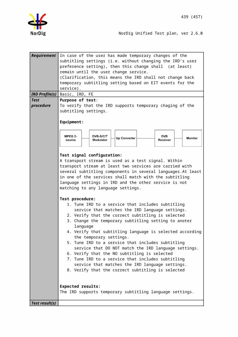
439 (457)
NorDig Unified Test plan, ver 2.6.0
Expected result:The IRD is able to initiate recording of several events that are part of the same content and it is indicated in the EPG. The IRD presents this in a user friendly way.
Test result(s)Conformity OK Fault Major Minor, define fail reason in commentsComments If possible describe if fault can be fixed with software update: YES NO
Describe more specific faults and/or other information
Date Sign
Task 13:16 Split recordings- dynamic update of EIT
Section NorDig Unified 14.3.4Requirement During the lifecycle of EIT schedule broadcasters may change programmes from split to
single or vice versa.IRD Profile(s) Basic, PVR, IRD, FETest procedure Purpose of test:
To verify that IRD handles split recordings.
Equipment: IRD Under test Streams with events of same content:
o Stream 1: Event splitted dynamically(*) on the same channel with max. 3 hour gap between splitted events
o Stream 2: Event dynamically(*) splitted between two channels in different multiplexes with out gaps between splits
o Stream 3: Event dynamically(*) splitted between two channels in different multiplexes with gaps between splits (max. 3 hour)
o Stream 4: Event splitted dynamically(*) between two channels in different multiplexes with overlaps between splits
o Stream 5: A splitted event dynamically(*) changed to single event
* Dynamically means update of the event information to correspond the change of single program to a splitted program or a splitted program to a single program
Test procedure:1. Initiate recording of a event that is dynamically changed to splitted event or one
event from EPG.2. Verify that the IRD records the whole event.3. Repeat with all test streams
Expected result:The IRD is able to record dynamically changed splitted events.
Test result(s)Conformity OK Fault Major Minor, define fail reason in commentsComments If possible describe if fault can be fixed with software update: YES NO
Describe more specific faults and/or other information
Date Sign
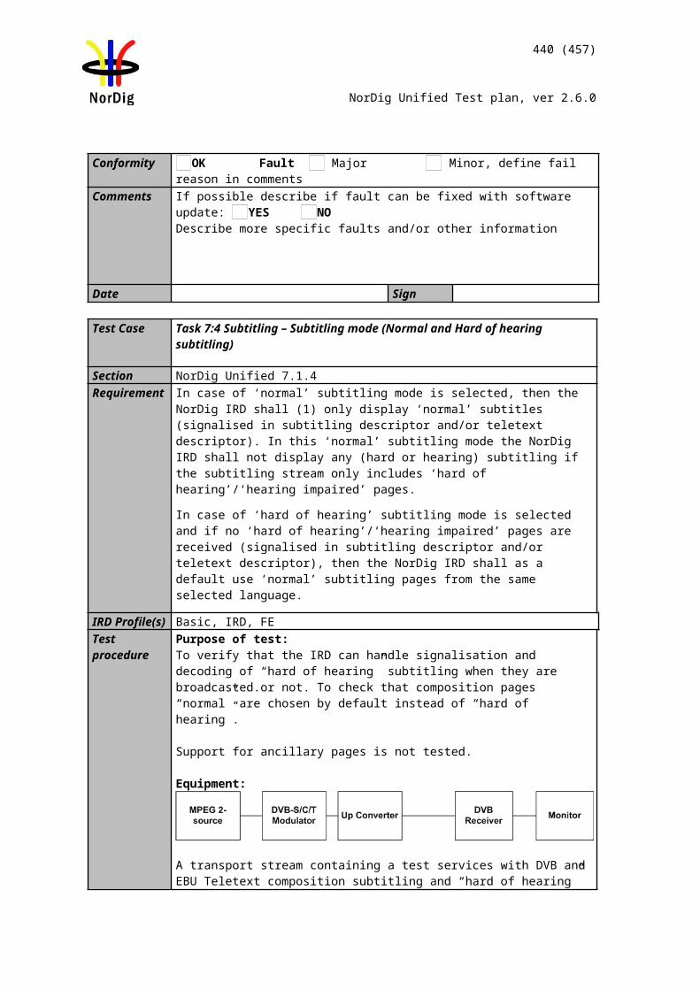
440 (457)
NorDig Unified Test plan, ver 2.6.0
Task 13:17 Recommended events
Section NorDig Unified 14.3.5Requirement When the event selected has one or more recommendation(s) associated with it
(signalised from original event with crid_type 0x03), the NorDig PVR should offer the option to record the recommendations (programme or series) as well as the selected programme or series.
Once selected, the appropriate recommended event(s) shall also be marked as selected to be recorded on the EPG display.
The recommended event(s) may also have recommendation(s) of its own. When user chooses to select to include the recommendation(s) into the recording, the NorDig PVR shall not include more than the original event’s recommendation(s) (i.e. the NorDig PVR shall not follow more than the original event’s initial recommendation and a recommendation should not be used to create a linked list of events to be recorded).
IRD Profile(s) Basic, PVR, IRD, FETest procedure Purpose of test:
To verify that IRD supports recommended events
Equipment:IRD Under testStream with EIT information including CRID for recommendations
Test procedure:1. Open EPG and schedule a event2. Verify that IRD recommended only events that are related to the schedule event3. Verify that it is possible to schedule recordings for recommended event
Expected results:The IRD supports recommended events
Test result(s)Conformity OK Fault Major Minor, define fail reason in commentsComments If possible describe if fault can be fixed with software update: YES NO
Describe more specific faults and/or other information
Date Sign
Task 13:18 Alternative Recording
Section NorDig Unified 14.3.6Requirement When scheduled recordings overlap, the NorDig PVR shall use the alternate instance
information (1), when provided, to record one or more of the programmes at their alternate times thereby minimising the conflict, subject to any device limitations (e.g. available space).
Where a programme is repeated in its entirety a broadcaster may assign the same programme CRID to both EIT events. The NorDig PVR should detect an alternative instance of a programme (as when two events has same programme CRID) (1). This can be used to assist in resolution of booking clashes.
Where alternate instances belong to the same series this allows the NorDig PVR to only record a single showing of each episode, usually the first.
IRD Profile(s) Basic, PVR, IRD, FE
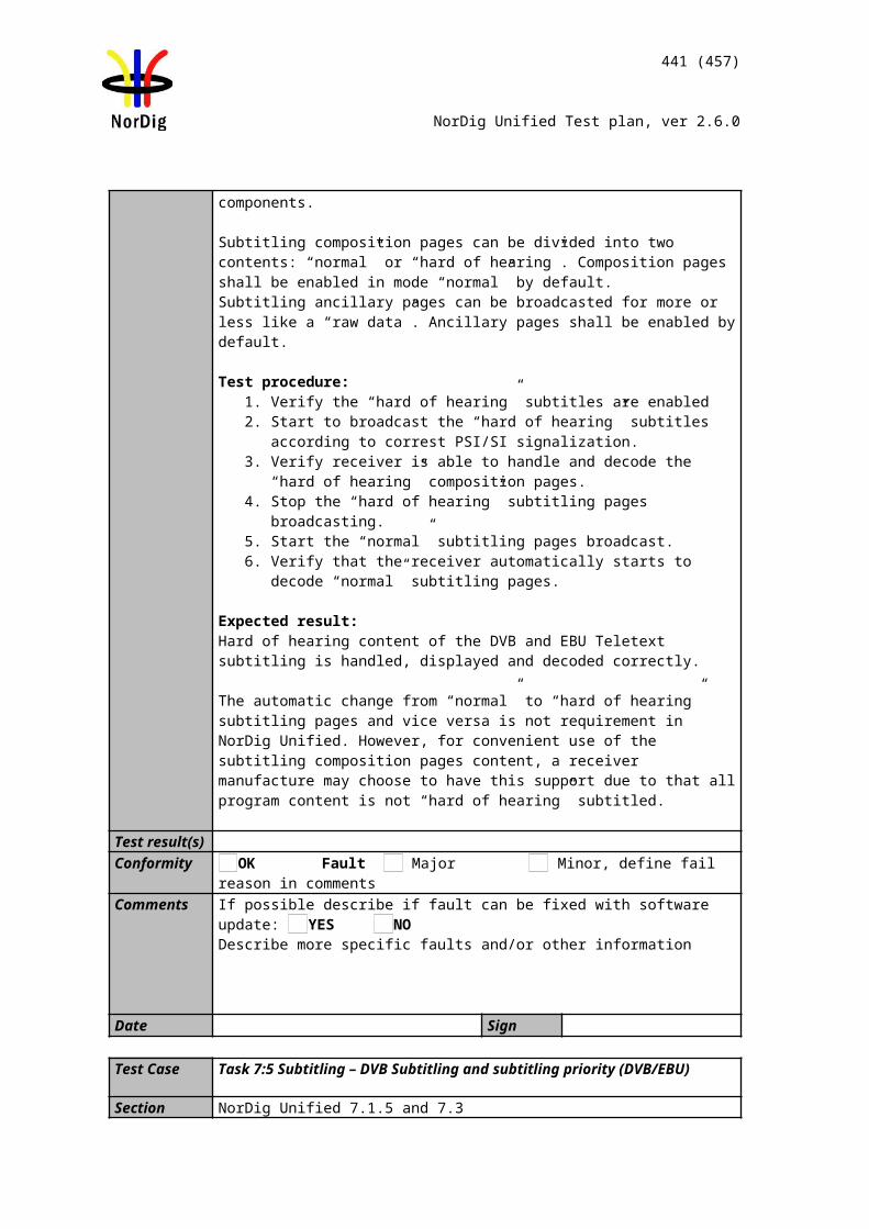
441 (457)
NorDig Unified Test plan, ver 2.6.0
Test procedure Purpose of test:To verify that IRD handles alternative instance recording.
Equipment: IRD Under test Stream 1: Recorded stream with split information about alternative instance of event
on same channel. Stream 2: Recorded stream with split information about alternative instance of event
on same channel.
Test procedure:1. Playout stream 1.2. Schedule an event conflicting with the event with alternative instance.3. The IRD shall notify that there is a collision but that there is an alternative instance
that can be recorded on the same service instead.4. Playout stream 2.5. Schedule an event conflicting with the event with alternative instance.6. The IRD shall notify that there is a collision but that there is an alternative instance
that can be recorded on another service instead.
Expected result:The IRD is able to use alternative information to record a programme at an alternative time in the case of conflict, including also on other TV sevices.
Test result(s)Conformity OK Fault Major Minor, define fail reason in commentsComments If possible describe if fault can be fixed with software update: YES NO
Describe more specific faults and/or other information
Date Sign
Task 13:19 Accurate Recording – EIT information present
Section NorDig Unified 14.3.7Requirement The NorDig PVR shall determine the timing of the recording through monitoring of the
EITschedule and EIT present/following information.The NorDig PVR shall record at least for the duration where the event ID in the EIT present table matches the event ID of the event selected from the EIT schedule to a pre-cision of 10 Seconds, unless there is a conflict with another recording event.
Where the Event ID is signalled in EIT present table early (in advance of the schedule start_time) the NorDig PVR shall start recording. As a minimum the NorDig PVR shall handle early starts of at least 10 minutes, provided there are no other recordings in progress.The NorDig PVR shall monitor the EIT schedule and EIT present/following for updates to the start time and duration such that any event will be captured should the schedule be updated no later than 2 minutes prior to the current scheduled time of broadcast.Where the Event ID does not appear within EITp/f (in neither the present nor following tables) within the expected schedule time and duration the NorDig PVR should record according to the scheduled start time and duration. If the event id appears in the EIT fol-lowing table at the scheduled start time, it means that the event is delayed and the NorDig PVR should wait with the start of the recording until the event ID appears in the EIT present table.The duration of the recording shall be changed even if the EITp/f is updated after the start time has elapsed, until the event is no longer present in the EIT present tab.
IRD Profile(s) Basic, PVR, IRD, FE
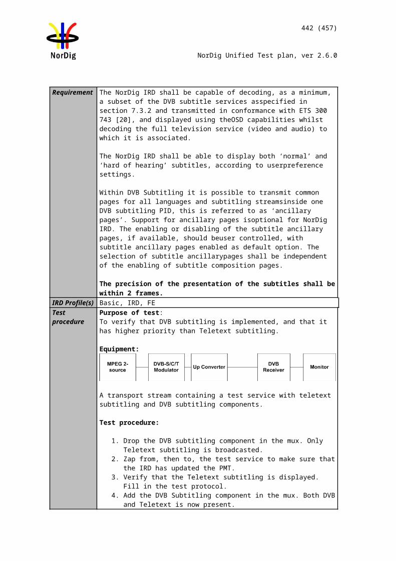
442 (457)
NorDig Unified Test plan, ver 2.6.0
Test procedure Purpose of test:To verify that IRD handles accurate recording based on the EIT information according to the PVR_rec minimum scenario.
Equipment:IRD Under testStream with EIT information that is updated accurately (EIT present table), having consequent EIT schedule and EIT p/f scenarios as follows:
EIT1: Event start_time1, duration = duration1. EIT2: Event start_time2 = start_time1-10min and duration2 ≠ duration1. EIT3: Event start_time3>start_time2, duration3 = duration2. EIT4: Event start_time4=start_time3, duration4=duration3. EIT5: Event start_time5=start_time4, duration5>duration4.
Each scenario consists of multiple EIT sections: Event shall be included in the EIT_schedule of EIT1. Event shall be included in the EIT_following of EIT2 and EIT3. Event shall be included in the EIT_present of EIT4 and EIT5. Event start_time and duration shall be constant in EIT_schedule during the test.
Event event_id shall be constant during the test. Event name or short_event_descriptor may be updated to indicate the originating EIT scenario number.
Test procedure:1. Broadcast EIT schedule and EIT p/f scenario EIT1.2. Schedule Event for recording from EPG/ESG.3. Set IRD into the stand-by mode.4. Update EIT scenario to EIT2, where Event start_time and duration are updated. 5. Shortly before start_time2, update EIT scenario to EIT3, where start_time is
delayed.6. Update EIT scenario to EIT4 at start_time3 so that Event is the present event.
7. While Event is present, update EIT scenario to EIT5, where duration is updated.
8. Fill in the measurement record.
Expected results:The IRD performs accurate recording based on the EIT present information. Recording should start at start_time4 or alternatively recording shall start at start_time2 ±10 s. Recording shall stop at start_time5+duration5±10 s.
Test result(s) Measurement recordTest point Result OK/NOK
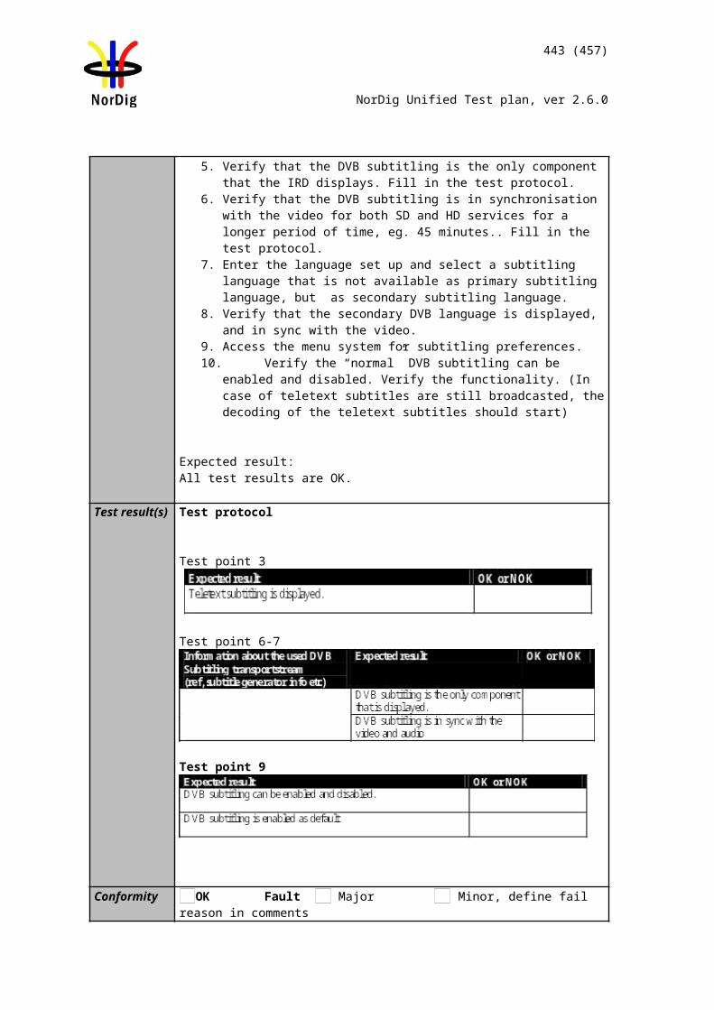
443 (457)
NorDig Unified Test plan, ver 2.6.0
IRD prioritizes EIT_present/following over EIT_scheduleIRD handles correctly an early start of a scheduled eventIRD handles correctly a delayed start of a scheduled event IRD handles EIT present duration update during recordingRecording begins according to EIT present ±10 s.Recording is stopped according to EIT present ± 10 s.Recording is not indicated as incomplete.Recording is correctly viewable
Conformity OK Fault Major Minor, define fail reason in commentsComments If possible describe if fault can be fixed with software update: YES NO
Describe more specific faults and/or other information
Date Sign
Task 13:20 Accurate Recording – EIT information missing
Section NorDig Unified 14.3.7Requirement Where the Event ID does not appear within EITp/f (in neither the present nor following
tables) within the expected schedule time and duration the NorDig PVR should record according to the scheduled start time and duration. If the event id appears in the EIT following table at the scheduled start time, it means that the event is delayed and the NorDig PVR should wait with the start of the recording until the event ID appears in the EIT present table.
The duration of the recording shall be changed even if the EITp/f is updated after the start time has elapsed, until the event is no longer present in the EIT present table.
If the NorDig PVR starts to record at the expected scheduled start time even if the event does not appear within EIT p/f, the recording shall be considered as incomplete.
Where there is a loss of signal or EIT present table is no longer being received, the NorDig PVR will continue to record at least until the end time of the event (defined by start_time plus duration) in the last received EITp/f. If the signal is restored the NorDig PVR will continue to record according to its normal operation.
IRD Profile(s) Basic, PVR, IRD, FE
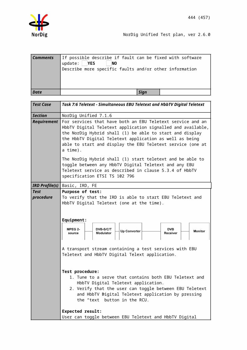
444 (457)
NorDig Unified Test plan, ver 2.6.0
Test procedure Purpose of test:To verify that IRD handles accurate recording based on the EIT information
Equipment:
Stream with EIT information that is updated (EIT present table)
Test procedure:1. Schedule an event for recording from EPG/ESG.2. Set IRD into the stand-by mode3. Remove EIT information 4. Verify that IRD checks the EIT information and updates recording before
scheduled recording.5. Verify that recording is completed as indicated at the initial time of the
recording and missing EIT present information do not change the initial recording.
Expected results:The IRD performs accurate recording without EIT information
Test result(s) Measurement recordTest point Result OK/NOKIRD checks the EIT information at least 10 min before scheduled recording takes placeRecording begins according to EIT schedule Recording is stopped according to EIT scheduleIRD indicates that the recording is incompleteThe recording is correctly viewable
Conformity OK Fault Major Minor, define fail reason in commentsComments If possible describe if fault can be fixed with software update: YES NO
Describe more specific faults and/or other information
Date Sign
Task 13:21 Accurate Recording – Loss of signal
Section NorDig Unified 14.3.7Requirement Where there is a loss of signal or EIT present table is no longer being received, the
NorDig PVR will continue to record at least untl the end time of the event (defined by start_time plus duration) in the last received EITp/f. If the signal is restored the NorDig PVR will continue to record according to its normal operation.
IRD Profile(s) Basic, PVR, IRD, FETest procedure Purpose of test:
To verify that IRD handles accurate recording in spite of reception problems.
Equipment:
Test stream shall contain EIT_actual schedule and present/following tables.
Test procedure:
TS Source MUX ExciterDVB Receiver
TS Source MUX ExciterDVB
Receiver
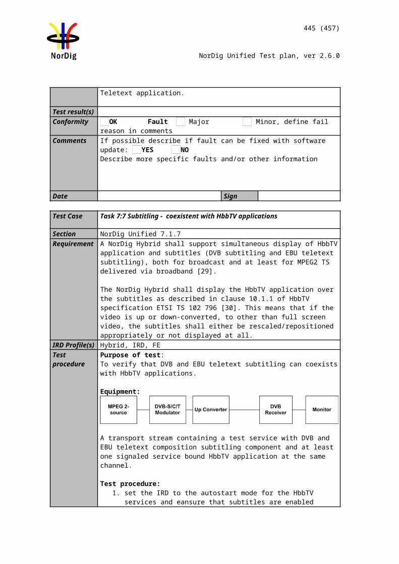
445 (457)
NorDig Unified Test plan, ver 2.6.0
1. Schedule the event ‘Test Event’ for recording from EPG2. Set IRD into the stand-by mode3. Disconnect IRD from the Exciter while the recording is ongoing.4. Re-connect the IRD to the Exciter before the end time of the event.5. Wake up the IRD from stand-by after the recording is completed.6. Play back the recording. 7. Fill in the measurement record.
Expected results:IRD is able to handle reception errors gracefully. IRD indicates the incomplete recordings.
Test result(s) Measurement recordTest point Result OK/NOKIRD continues recording after signal is re-connectedRecording is stopped at the end time of the eventIRD indicates that the recording is incompleteThe incomplete recording is viewable to the largest possible extent
Conformity OK Fault Major Minor, define fail reason in commentsComments If possible describe if fault can be fixed with software update: YES NO
Describe more specific faults and/or other information
Date Sign
Task 13:22 Accurate Recording – EIT update in stand-by
Section NorDig Unified 14.3.7Requirement In standby mode (where the NorDig PVR IRD is not decoding any transport stream) the
NorDig PVR shall have the capability to power on automatically twice per day to update the EIT and scheduled recordings. There may be an option to amend the time of power on or to switch off the facility as a user option, but factory default for this shall be that it is on.
IRD Profile(s) Basic, PVR, IRD, FETest procedure Purpose of test:
To verify that IRD check the EIT schedule information at least twice per day in stand-by mode
Equipment:IRD Under testStream with EIT information that is updated
Test procedure:1. Schedule a recording from ESG/EPG for 24 hours from current time.2. Set IRD to stand-by mode.3. While IRD is in stand-by mode, update the EIT Schedule information so that
the start times and durations of the scheduled recording are changed.4. After 12 hours, update the EIT Schedule information again.5. Verify that IRD updates the EIT information at least twice a day and performs
the recordings correctly according to the changed EIT information. 6. Verify that IRD has performed the recordings correctly according to the
updated EIT Schedule.
Expected results:
446 (457)
NorDig Unified Test plan, ver 2.6.0
The IRD IRD checks the EIT information and updates the recording accordingly at least twice a day.
Test result(s)Conformity OK Fault Major Minor, define fail reason in commentsComments If possible describe if fault can be fixed with software update: YES NO
Describe more specific faults and/or other information
Date Sign
Test Case Task 13:23 Simultaneous recording – OTR and viewing
Section NorDig Unified 14.3.8 and 14.3.15Requirement The NorDig PVRs shall be able to record one service while viewing another, indepen-
dently even if theservices are on different transport streams.IRD Profile(s) Basic, PVR, IRD, FETest procedure Purpose of test:
To verify that the IRD handles the simultaneous recording.
Test Equipment:Live network or a test network of at least 2 MUX with both SD and HD services (TBD).
Test procedure:1. Initiate OTR.2. Zap to a service on another multiplex.3. Watch and change the service for a few times.4. Stop OTR.5. Play back the recording
Expected results:The NorDig PVRs shall be able to record one service while viewing another, independently even if theservices are on different transport streams.
Test result(s) Measurement recordTest point Result OK/NOKIRD is able to tune to another service while recording.OTR recording does not disturb viewing.Viewing does not disturb the recording.Channel change does not disturb the recording.
Conformity OK Fault Major Minor, define fail reason in commentsComments If possible describe if fault can be fixed with software update: YES NO
Describe more specific faults and/or other information
Date Sign
Test Case Task 13:24 Simultaneous recording – Scheduled recording and viewing
Section NorDig Unified 14.3.8 and 14.3.16Requirement The NorDig PVRs shall be able to record one service while viewing another, indepen-
dently even if theservices are on different transport streams.IRD Profile(s) Basic, PVR, IRD, FETest procedure Purpose of test:
To verify that the IRD handles the simultaneous recording.
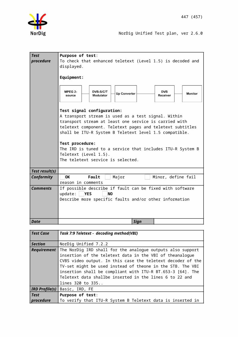
447 (457)
NorDig Unified Test plan, ver 2.6.0
Test Equipment:Live network or a test network of at least 2 MUX with both SD and HD services (TBD).
Test procedure:1. Schedule a recording from EPG/ESG.2. Zap to a service on another multiplex.3. Watch and change the service for a few times until the scheduled recording is
completed.4. Play back the recording.
Expected results:The NorDig PVRs shall be able to record one service while viewing another, independently even if theservices are on different transport streams.
Test result(s) Measurement recordTest point Result OK/NOKIRD is able to tune to another service while scheduled recording is ongoing.Scheduled recording does not disturb viewing.Viewing does not disturb the recording.Channel change does not disturb the recording.
Conformity OK Fault Major Minor, define fail reason in commentsComments If possible describe if fault can be fixed with software update: YES NO
Describe more specific faults and/or other information
Date Sign
Test Case Task 13:25 Simultaneous recording – OTR and time-shift
Section NorDig Unified 14.3.8, 14.3.12, 14.3.15 and 14.4.2Requirement The NorDig PVR should be able to record a background service (that is not viewed) at
the same time as timeshift record the viewing service, independently if the services are on different transport streams.
IRD Profile(s) Basic, PVR, IRD, FETest procedure Purpose of test:
To verify that the IRD handles the simultaneous recording and timeshift.
Test Equipment:Live network or a test network of at least 2 MUX with both SD and HD services (TBD).
Test procedure:1. Initiate OTR.2. Zap to a service on another multiplex.3. Initiate timeshift and pause viewing for few minutes.4. View, Fast forward, Rewind and Pause the timeshifted video in a random
pattern. 5. Fast forward the playback the timeshifted content to real time. Rewind and
view.6. Stop the timeshift. 7. Stop OTR.8. Play back the recording.
Expected results:
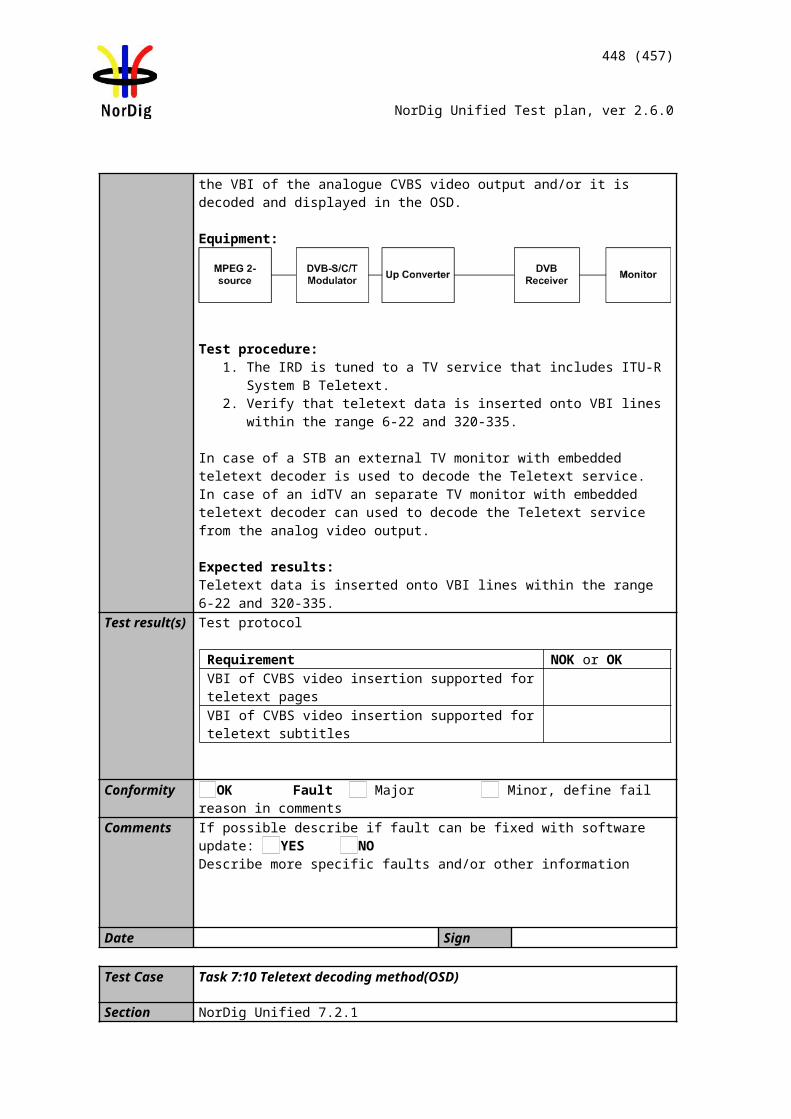
448 (457)
NorDig Unified Test plan, ver 2.6.0
The NorDig PVR is able to timeshift another service while recording.
Test result(s) Measurement recordTest point Result OK/NOKIRD is able to timeshift another service while recording.OTR recording does not disturb timeshift functionality.Timeshift pause does not disturb the recording.Timeshift viewing does not disturb the recording.Timeshift FF/REW/PAUSE does not disturb the recording.
Conformity OK Fault Major Minor, define fail reason in commentsComments If possible describe if fault can be fixed with software update: YES NO
Describe more specific faults and/or other information
Date Sign
Test Case Task 13:26 Simultaneous recording – Scheduled recording and time-shift
Section NorDig Unified 14.3.8, 14.3.12, 14.3.16 and 14.4.2Requirement The NorDig PVR should be able to record a background service (that is not viewed) at
the same time as timeshift record the viewing service, independently if the services are on different transport streams.
IRD Profile(s) Basic, PVR, IRD, FETest procedure Purpose of test:
To verify that the IRD handles the simultaneous recording and timeshift.
Test Equipment:Live network or a test network of at least 2 MUX with both SD and HD services (TBD).
Test procedure:1. Schedule a recording from EPG/ESG.2. Zap to a service on another multiplex.3. Initiate timeshift and pause viewing for few minutes.4. View, Fast forward, Rewind and Pause the timeshifted video in a random
pattern. 5. Chase playback the timeshifted content to real time. Rewind and view again.5. Stop the timeshift after the scheduled recording is completed.6. Play back the recording.
Expected results:The NorDig PVR is able to timeshift another service while recording.
Test result(s) Measurement recordTest point Result OK/NOKIRD is able to timeshift another service while recording.Scheduled recording does not disturb timeshift functionality.Timeshift pause does not disturb the recording.Timeshift viewing does not disturb the recording.Timeshift replay and trick modes do not disturb the recording.
Conformity OK Fault Major Minor, define fail reason in commentsComments If possible describe if fault can be fixed with software update: YES NO
Describe more specific faults and/or other information
Date Sign
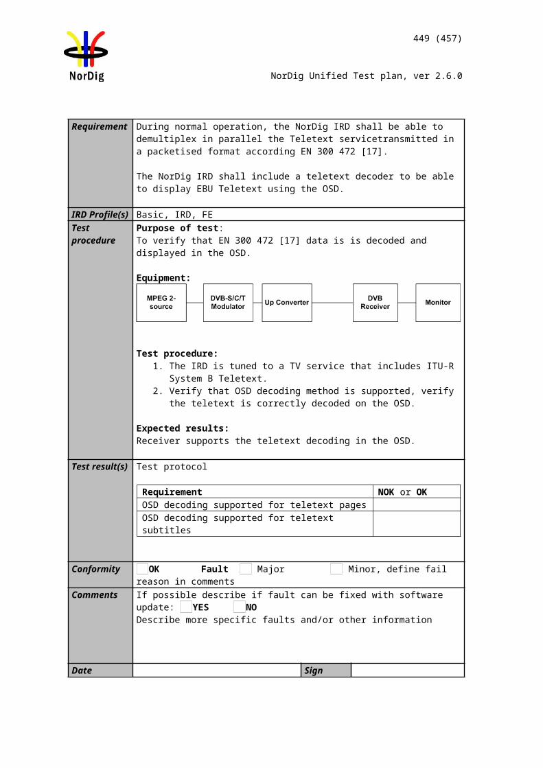
449 (457)
NorDig Unified Test plan, ver 2.6.0
Test Case Task 13:27 Simultaneous recording and playback
Section NorDig Unified 14.4.4Requirement The NorDig PVR shall be able to record and playback simultaneously. It shall be possi-
ble to record one service from the live transmissions while playback another earlier recording.The user shall be also able to start the playback of a recording for which the recording has not yet completed (“chase playback”).
IRD Profile(s) Basic, PVR, IRD, FETest procedure Purpose of test:
To verify that the IRD handles the simultaneous recording and playback.
Test Equipment:Live network or a test network of at least 2 MUX with both SD and HD services (TBD).
Test procedure:1. Initiate OTR.2. Zap to a service on another multiplex.3. Play back the recording initiated in test step 1.4. View, Fast forward, Rewind and Pause the timeshifted video in a random
pattern. 5. Fast forward the playback the timeshifted content to real time. Rewind and
view.6. Stop the playback. 7. Stop OTR.8. Play back the recording.
Expected results:The NorDig PVRs shall be able to record and playback simultaneously. Chase playback is possible.
Test result(s) Measurement recordTest point Result OK/NOKIRD is able to playback an ongoing recording.Playback does not disturb the recording functionality.Playback pause does not disturb the recording.Playback viewing does not disturb the recording.Playback FF/REW does not disturb the recording.
Conformity OK Fault Major Minor, define fail reason in commentsComments If possible describe if fault can be fixed with software update: YES NO
Describe more specific faults and/or other information
Date Sign
Task 13:28 Back-to-back recordings – Static EIT information
Section NorDig Unified 14.3.11, 14.3.16.2Requirement The NorDig PVR shall be able to record back-to-back events both on same and on
different services.
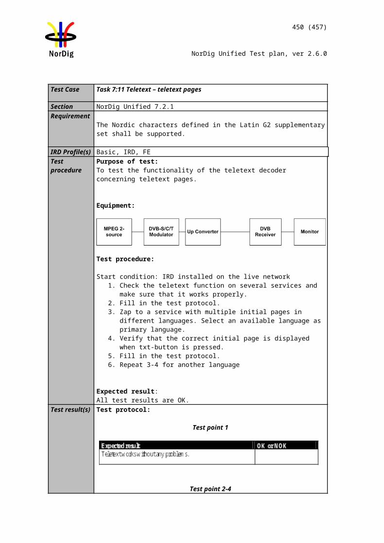
450 (457)
NorDig Unified Test plan, ver 2.6.0
Back-to-back events refer to two events that immediately follow each other, i.e. the following event start_time is immediately after the previous events stop time,(start_time plus duration).
For overlapping events see NorDig Unified 14.3.16.2. If the first event has same or higher priority as the second event (see 14.3.16.2) and the first event will overrun, if the NorDig PVR has limitation in recording capacity, it shall first finalise recording of the first event (including its overrun part) before starting recording the next event.
The overrun shall be treated as the more important part of the events, see figure below.If the NorDig PVR has been set to add additional recording time (“safe margins”) before and after recorded events’ start and stop time, any overlapping “safe margins” between the back-to-back events shall be removed (if the NorDig PVR has limitation in recording capacity for this)
If a conflict occurs in a partially or completely overlapping recording after the time ofprogramming the NorDig PVR shall prioritize the recording with the highest priority , as illustrated in figures below. For conflict with events with same priority, the NorDig PVR shall first finalize the first recording (including any late over-run) before starting with next. (See also back-to-back recording).
IRD Profile(s) Basic, PVR, IRD, FETest procedure Purpose of test:
To verify that IRD handles back-to-back recording
Equipment:IRD Under testTest network of at least 2 MUX, with services as follows:
Services with EIT information that indicate programs are back-to-back Services with EIT information that indicate programs are overlapping
Example: For all scheduled events, start_timeN=(start_timeN-1+durationN-1)
Example: For all scheduled events, start_timeN<(start_timeN-1+durationN-1)
Test procedure:1. Schedule recordings from EPG that are back-to-back2. Verify that the events are recorded corretly3. Verify that playback of the events are correct4. Schedule recordings from EPG that are overlapping5. Verify that the events are recorded correctly (in conflict situation, the earlier
recording has the priority)6. Verify that playback of the events are correct
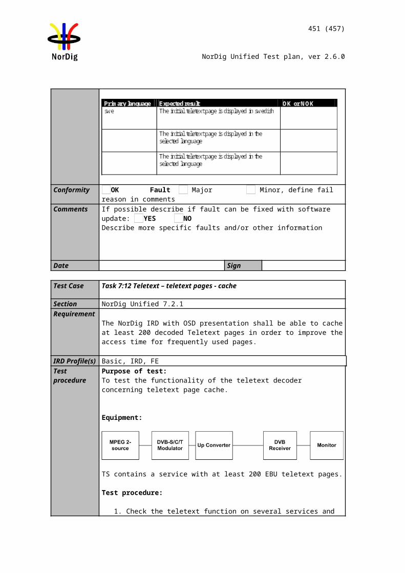
451 (457)
NorDig Unified Test plan, ver 2.6.0
Expected results:The IRD handles back-to-back recording correctly.
Test result(s) Measurement recordTest point Result OK/NOKIRD records back-to-back events correctly from
- the same service- different services on same multiplex- different services on different multiplexes
IRD records overlapping events correctly from - the same service- different services on same multiplex- different services on different multiplexes
IRD handles possible recording conflicts correctlyConformity OK Fault Major Minor, define fail reason in commentsComments If possible describe if fault can be fixed with software update: YES NO
Describe more specific faults and/or other information
Date Sign
Task 13:29 Back-to-back recordings – Changes in EIT information
Section NorDig Unified 14.3.11, 14.3.16.2Requirement The NorDig PVR shall be able to record back-to-back events both on same and on
different services.
Back-to-back events refer to two events that immediately follow each other, i.e. the following event start_time is immediately after the previous events stop time,(start_time plus duration).
For overlapping events see NorDig Unified 14.3.16.2. If the first event has same or higher priority as the second event (see 14.3.16.2) and the first event will overrun, if the NorDig PVR has limitation in recording capacity, it shall first finalise recording of the first event (including its overrun part) before starting recording the next event.
The overrun shall be treated as the more important part of the events, see figure below.If the NorDig PVR has been set to add additional recording time (“safe margins”) before and after recorded events’ start and stop time, any overlapping “safe margins” between the back-to-back events shall be removed (if the NorDig PVR has limitation in recording capacity for this)
If a conflict occurs in a partially or completely overlapping recording after the time ofprogramming the NorDig PVR shall prioritize the recording with the highest priority , as illustrated in figures below. For conflict with events with same priority, the NorDig PVR shall first finalize the first recording (including any late over-run) before starting with next. (See also back-to-back recording).
IRD Profile(s) Basic, PVR, IRD, FETest procedure Purpose of test:
To verify that IRD handles back-to-back recording with dynamic update in EIT
Equipment:IRD Under testTest network of at least 2 MUX, with services as follows:
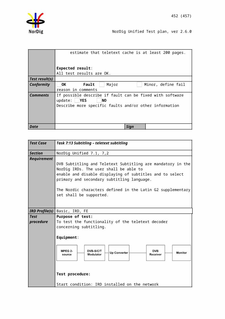
452 (457)
NorDig Unified Test plan, ver 2.6.0
Services with EIT information updated to indicate programs are back-to-back Services with EIT information updated to indicate programs are overlapping
Initial situation example: For all scheduled events, start_timeN>(start_timeN-1+durationN-1)
Example: For all scheduled events, start_timeN=(start_timeN-1+durationN-1)
Example: For all scheduled events, start_timeN<(start_timeN-1+durationN-1)
Test procedure:1. Schedule recordings from EPG as per the initial situation.2. Update the EIT in a way that the events will be back-to-back3. Verify that the events are recorded corretly4. Verify that playback of the events are correct5. Schedule recordings from EPG as per the initial situation.6. Update the EIT in a way that the eventsthat will be overlapping7. Verify that the events are recorded correctly (the earlier recording has the
priority)8. Verify that playback of the events are correct
Expected results:The IRD handles back-to-back recording correctly with dynamic update of EIT information
Test result(s) Measurement record:Test point Result OK/NOKIRD records back-to-back events correctly from
- the same service- different services on same multiplex- different services on different multiplexes
IRD records overlapping events correctly from - the same service- different services on same multiplex- different services on different multiplexes
IRD handles possible recording conflicts correctlyConformity OK Fault Major Minor, define fail reason in comments
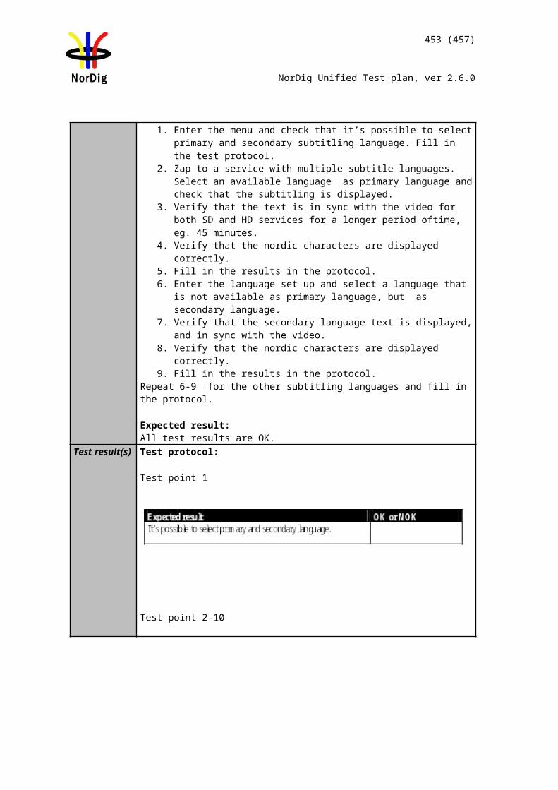
453 (457)
NorDig Unified Test plan, ver 2.6.0
Comments If possible describe if fault can be fixed with software update: YES NODescribe more specific faults and/or other information
Date Sign
Task 13:30 Timeshift recording
Section NorDig Unified 14.3.12Requirement The NorDig PVR shall be able to pause or timeshift live TV for at least 60 minutes. It
should be possible to save time-shifted events into the PVR list of recordings.IRD Profile(s) Basic, PVR, IRD, FETest procedure Purpose of test:
To verify that IRD supports timeshift recording.
Equipment: IRD Under test Live stream or test network with SD and HD services, containing video, multiple
audio and multiple subtitling components and teletext
Test procedure:1. Pause the live view on a channel2. Verify that the IRD is able to timeshift for at least 60 minutes.3. Start the viewing of paused content.4. Verify that the timeshifted content is played out correctly and all components are
available.
Expected result:The paused content can be viewed from the point where the broadcast was paused by pressing a single button and the trick modes can be used in chased playback.
Test result(s) Measurement recordTest point Result OK/NOKTimeshift duration is at least 60 minutesIRD is able to play back all service components in time-shift
Conformity OK Fault Major Minor, define fail reason in commentsComments If possible describe if fault can be fixed with software update: YES NO
Describe more specific faults and/or other information
Date Sign
Task 13:31 Manual recording
Section NorDig Unified 14.3.14Requirement The NorDig PVR shall make it possible for the viewer to set a manual recording,
without using the EPG/ESG/EIT data, by setting the service, start-time and end-time (or duration).
The time and date for the user when programming shall be the local time, including any offset, at the time of recording according to the IRD’s settings, and not the local time at the time of programming.This means that if there is a change in local time offset (e.g. change in daylight-saving time) between the time of programming and the time of recording, the time and date shall refer to the new local time at the time of recording.
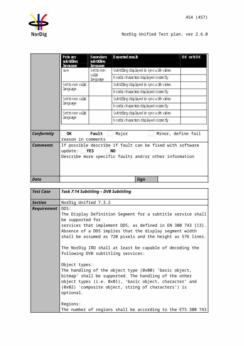
454 (457)
NorDig Unified Test plan, ver 2.6.0
It should be possible to set weekly repeated manual recording (like every Monday 19:00:00 to 20:00:00 or every weekday between 12:00:00 to 12:15:00)
IRD Profile(s) Basic, PVR, IRD, FETest procedure Purpose of test:
To verify that IRD
Equipment: IRD Under test Live stream or test network with SD and HD services, containing video, multiple
audio and multiple subtitling components and teletext
Test procedure:1. Schedule a recording by setting a manual timer.2. Playback recording initiated by the manual timer
Expected result:The IRD is able to initiate recordings using manual timers.
Test result(s)Conformity OK Fault Major Minor, define fail reason in commentsComments If possible describe if fault can be fixed with software update: YES NO
Describe more specific faults and/or other information
Date Sign
Task 13:32 Manual recording – Changes in TDT/TOT
Section NorDig Unified 14.3.14Requirement The NorDig PVR shall make it possible for the viewer to set a manual recording,
without using the EPG/ESG/EIT data, by setting the service, start-time and end-time (or duration).
The time and date for the user when programming shall be the local time, including any offset, at the time of recording according to the IRD’s settings, and not the local time at the time of programming.This means that if there is a change in local time offset (e.g. change in daylight-saving time) between the time of programming and the time of recording, the time and date shall refer to the new local time at the time of recording.
It should be possible to set weekly repeated manual recording (like every Monday 19:00:00 to 20:00:00 or every weekday between 12:00:00 to 12:15:00)
IRD Profile(s) Basic, PVR, IRD, FE
455 (457)
NorDig Unified Test plan, ver 2.6.0
Test procedure Purpose of test:To verify that IRD supports daylight saving changes.
Equipment: IRD Under test Live stream or test network having a time offset change
Test procedure:1. Schedule a recording for an event after the time offset change indicated in the
time_of_change field in the local_time_offset_descriptor of TOT. 2. Set the IRD to standby.3. Wait until the time event for the time offset change has been passed. 4. Resume the IRD from standby. 5. Verify that the recording start time and duration are correctly as scheduled.6. Verify that the recording is played back correctly.
Expected result:The IRD is able to initiate recordings using manual timers and recording is according summer/wintertime change correctly.
Test result(s) Measurement recordTest point Result OK/NOKScheduled recordings are planned for the local time during the recordingIRD is able to perform manual recordings correctly when time offset decreasesIRD is able to perform manual recordings correctly when time offset increases
Conformity OK Fault Major Minor, define fail reason in commentsComments If possible describe if fault can be fixed with software update: YES NO
Describe more specific faults and/or other information
Date Sign
Task 13:33 One Touch Recording (OTR)
Section NorDig Unified 14.3.15Requirement The NorDig PVR shall include a direct recording setting as a One-touch recording
(OTR) function which allows the user to start a recording, while watching live TV, with one button press on the remote control.
This One-touch recording shall not be delayed by further requests for user interaction unless to proceed would affect a recording that is either already underway or scheduled to start before the end of the OTR recording.
The duration of the One-touch recording operation shall be based on either a pre-set time or current viewed event.
IRD Profile(s) Basic, PVR, IRD, FETest procedure Purpose of test:
To verify that IRD supports one-touch recording.
Equipment: IRD Under test Live stream or test network
Test procedure:
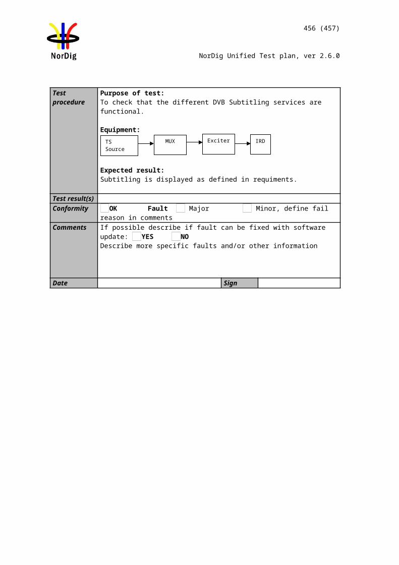
456 (457)
NorDig Unified Test plan, ver 2.6.0
1. Watch a channel for a few minutes2. Press record button to start recording.3. Wait for a few minutes.4. Stop recording using the remote control button for ‘stop’.5. Press again record button for OTR. 6. Change volume, view teletext and toggle between different available subtitling and
audio components. Set the IRD to stand-by and wake it up.7. Wait until the default recording duration has exceed.8. View the recordings.9. Fill in the measurement record.
Expected result:The IRD is able to initiate a recording by pressing dedicated record button
Test result(s) Measurement recordTest point Result OK/NOKIRD begins the OTR immediately after user has pressed the ‘Record’ button unless overridden by conflict handling.OTR default duration is either a pre-set time or until the end of the event.OTR is automatically stopped after default duration has exceed.OTR is not disturbed by user actions.
Conformity OK Fault Major Minor, define fail reason in commentsComments If possible describe if fault can be fixed with software update: YES NO
Describe more specific faults and/or other information
Date Sign
Task 13:34 Automatic Conflict Handling – During programming
Section NorDig Unified 14.3.16.1Requirement If a conflict is detected it shall be indicated immediately to the user, together with details
of the cause, so that the user can take appropriate action.
When programming a recording which comes in conflict with an earlier programmed recording and when the NorDig PVR can detect an alternative instance in one or both of them, the NorDig PVR shall either automatically re-program one of the to the alternative instance or propose that viewer solve the conflict by moving one of the recordings to the alternative instance and asking for confirmation.
IRD Profile(s) Basic, PVR, IRD, FETest procedure Purpose of test:
To verify that IRD detects conflict in during recordings programming
Equipment:IRD Under testLive signal or test streams with EIT information containing overlapping events. Conflicting events shall be tested also as signalized with alternative instances, if supported by the broadcaster.
Test procedure:1. Watch a channel for a few minutes2. Schedule an event ‘Event1’ with start_time1 and duration1 for recording from
ESG/EPG.3. Schedule an another event on a different channel on the same multiplex that will
overlap with the previous recording causing a conflict in the IRD recording
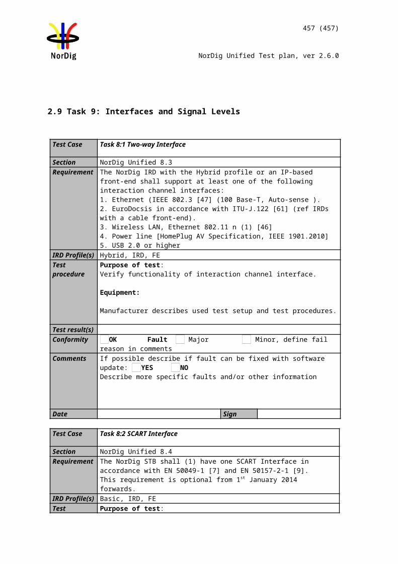
457 (457)
NorDig Unified Test plan, ver 2.6.0
resources.a. Event with start_time2 = start_time1b. Event with start_time2 < start_time1c. Event with start_time2 > start_time1d. Event with start_time2 < start_time1 and start_time2+duration2 >
start_time1+duration1e. Event with start_time2 > start_time1 and start_time2+duration2 <
start_time1+duration14. Repeat the test with events on a different multiplex5. Fill in the measurement record.
Expected results:The IRD detects conflict during programming of the recordings
Test result(s) Measurement recordTest point Status OK/NOKIRD indicates overlapping scheduled recordings on same multiplex immediately when the conflict is detectedIRD indicates overlapping scheduled recordings on different multiplexes immediately when the conflict is detectedIRD proposes to adjust the overlapping recordings or proposes automatically a new instance of the same eventConflict indication includes details of the cause.
Conformity OK Fault Major Minor, define fail reason in commentsComments If possible describe if fault can be fixed with software update: YES NO
Describe more specific faults and/or other information
Date Sign
Task 13:35 Automatic Conflict Handling – After programming
Section NorDig Unified 14.3.16.2Requirement If the NorDig PVR has a number of active programmed series recordings and if there
occurs a request of more simultaneous recordings than the NorDig PVR is capable of handling, the NorDig PVR shall be able to handle this without user confirmation at the time of actual recording, i.e. the IRD may inform of the conflict via the OSD but shall automatically solve the conflict at the time of actual recording if the user does not manually change the conflict handling.
Any information on OSD about conflict shall not be included in recording and shall have a time-out if no user reaction. All requests for user confirmation shall be done during the time of programming or during the setting of user preferences.
The conflict(s) shall be solved with higher priority recordings having preference before recordings with a lower priority. It is up to the NorDig PVR manufacture to define the PVR’s priority list, however it may typically be as prioritised in Table 14.1. Conflict(s) of recording with same priority level shall also be automatically solved (at least one of them shall be recorded), but it is up to the NorDig PVR manufacture to define a mechanism. The NorDig PVR should offer for the user the ability to change the conflict priority in the user preferences.
IRD Profile(s) Basic, PVR, IRD, FE
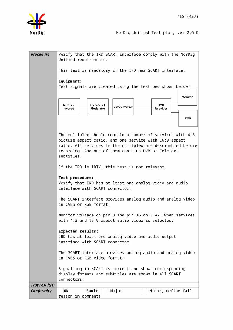
458 (457)
NorDig Unified Test plan, ver 2.6.0
Test procedure Purpose of test:To verify that IRD detects conflict in during recording
Equipment:IRD Under testLive signal or test streams with EIT information updated to have overlapping events. Conflicting events shall be tested also as signalized with alternative instances, if supported by the broadcaster.
Test procedure:1. Watch a channel for a few minutes.2. Schedule an event ‘Event’ with start_time and duration for recording from
ESG/EPG.3. Start OTR on a different channel on the same multiplex that will overlap with
the previous recording causing a conflict in the IRD recording resources.a. OTR is started before start_timeb. OTR is started after start_time
4. Repeat the test with events on different multiplexes.5. Fill in the measurement record.
Expected results:The IRD detects conflict during recording and resolves the conflict automatically
Test result(s) Measurement recordTest point Status OK/NOKIRD indicates if recording is overlapping with scheduled recordings on the same multiplexIRD indicates if recording is overlapping with scheduled recordings on different multiplexesOSD about conflict has a time-out and IRD adjusts the overlapping recordings or re-programs automatically a new instance of the same event unless overridden by user actions.Automatic conflict handling does not disturb the recording with higher priority.
Conformity OK Fault Major Minor, define fail reason in commentsComments If possible describe if fault can be fixed with software update: YES NO
Describe more specific faults and/or other information
Date Sign
Task 13:36 Maximum length of recordings
Section NorDig Unified 14.3.17Requirement If the is a failure within the transmission of the EIT and other transmission errors, the
NorDig PVR shall stop recording 4 hours after scheduled duration of the event has passed (even if the event still appears in EIT present table).
For events that have a duration that is longer than 8 hours, the NorDig PVR may stop recording after 8 hours.
IRD Profile(s) Basic, PVR, IRD, FE
459 (457)
NorDig Unified Test plan, ver 2.6.0
Test procedure Purpose of test:To verify that IRD records maximum time specified.
Equipment:IRD Under testStream or life network with EIT information
Test procedure:1. Schedule an event for recording that has duration of more than 8 hours.2. Verify that IRD has recorded the event for at least 8 hours
3. Schdule an event (less than 4 hours) and take a note of the ending time of the event.
4. Remove EIT information.5. Verify that IRD stops recording 4 hours after the original end time of the event.
6. Schdule an event (more than 4 hours) and take a note of the ending time of the event.
7. Remove EIT information.8. Verify that IRD stops recording 4 hours after the original end time or 8 hours
after from the beginning of the recording.
Expected results:The IRD handles max. length of recordings.
Test result(s)Conformity OK Fault Major Minor, define fail reason in commentsComments If possible describe if fault can be fixed with software update: YES NO
Describe more specific faults and/or other information
Date Sign
Task 13:37 Recording of parallel broadcast
Section NorDig Unified 14.3.19Requirement Some services and events are parallel broadcasted in multiple versions. In this context a
parallel broadcast of same programme event is identified that all service’s events have the same programme_CRID. Examples of parallel broadcasts are services with same national content but with different regional content and services with same content but with different resolution ie SD and HD simulcast broadcast services. The NorDig IRD that has been programmed to record an event with a specific programme_crid or series_crid which a programme_crid is part of, shall only record one instance of the event from one of the services when the event is parallel broadcasted over several services at the same time.
IRD Profile(s) Basic, PVR, IRD, FE
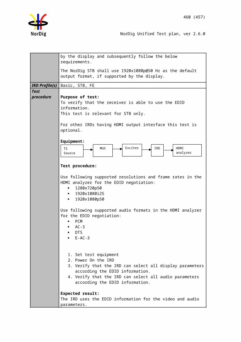
460 (457)
NorDig Unified Test plan, ver 2.6.0
Test procedure Purpose of test:To verify that IRD handles recordings with parallel broadcasts.
Equipment:IRD Under testLive stream or test network with EIT information. The network shall have simultaneous parallel broadcasts of events with equal programme_crid.
Test procedure:1. Schedule an event with multiple parallel broadcasts for recording.2. Verify that IRD records only one of the event instances.
Expected results:The IRD handles recordings with parallel broadcasts.
Test result(s)Conformity OK Fault Major Minor, define fail reason in commentsComments If possible describe if fault can be fixed with software update: YES NO
Describe more specific faults and/or other information
Date Sign
Task 13:38 Playback - General
Section NorDig Unified 14.4.1Requirement The NorDig PVR shall be able to playback recordings of all supported service types
(TV, radio etc) and all belonging components/PIDs (as described in 14.4.5).Only the service related interactive applications from the current viewed service (live or playback) are required to be active, this means that during playback all interactive applications from the live service in the background may be terminated.
IRD Profile(s) Basic, PVR, IRD, FETest procedure Purpose of test:
To verify that IRD is able to play back the recordings it has performed with all belonging components/PIDs.Equipment:IRD Under testLive stream or test network.
Test procedure:
The requirement in this test will be verified in the following test tasks.
Expected results:IRD is successfully able to play back the recordings.
Test result(s)Conformity OK Fault Major Minor, define fail reason in commentsComments If possible describe if fault can be fixed with software update: YES NO
Describe more specific faults and/or other information
Date Sign
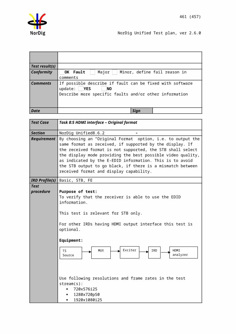
461 (457)
NorDig Unified Test plan, ver 2.6.0
Task 13:39 Replay/Playback – trick modes in playback
Section NorDig Unified 14.4.2Requirement The NorDig PVR shall support the following trick modes during playback of recorded
events (incl timeshift) for all supported video formats/codecs:• Play (playback at normal speed)• Pause• Stop (stop may be combined with pause, but must enable an easy way to stop play-back and return to list of recordings and live viewing mode)• Fast forward and shall support fast forward at minimum 3 different speeds, (like x3, x6, x15 and x30).• Fast reverse and should support fast reverse at minimum 3 different speeds, (like x3, x6, x15 and x30).
IRD Profile(s) Basic, PVR, IRD, FETest procedure Purpose of test:
To verify that IRD handles correctly different trick modes in playback.Equipment:IRD Under testLive stream or test network.
Test procedure:1. Play back recordings with different kinds of video, audio and subtitling
components.2. Pause and resume the playback. Repeat for several times with various
durations, from few seconds up to several minutes.3. Fast forward the recording. Toggle between different FF speeds. Resume
playback from each available FF speed.4. Rewind the recording. Toggle between different REW speeds, if available.
Resume playbackfrom each available REW speed.5. Stop the playback.6. Fill in the measurement record.
Expected results:The IRD handles different trick modes. Playback is not disturbed by usage of the trick modes.
Test result(s) Measurement recordTest point Result OK/NOKIRD has Pause mode in playback and it works correctly.IRD has 3 or more different FF speeds.IRD has REW functionality (with 1 or more speeds)
Conformity OK Fault Major Minor, define fail reason in commentsComments If possible describe if fault can be fixed with software update: YES NO
Describe more specific faults and/or other information
Date Sign
Task 13:40 Replay/Playback – trick modes in timeshift
Section NorDig Unified 14.4.2
462 (457)
NorDig Unified Test plan, ver 2.6.0
Requirement The NorDig PVR shall support the following trick modes during playback of recorded events (incl timeshift) for all supported video formats/codecs:• Play (playback at normal speed)• Pause• Stop (stop may be combined with pause, but must enable an easy way to stop play-back and return to list of recordings and live viewing mode)• Fast forward and shall support fast forward at minimum 3 different speeds, (like x3, x6, x15 and x30).• Fast reverse and should support fast reverse at minimum 3 different speeds, (like x3, x6, x15 and x30).
IRD Profile(s) Basic, PVR, IRD, FETest procedure Purpose of test:
To verify that IRD handles correctly different trick modes in timeshift.Equipment:IRD Under testLive stream or test network.
Test procedure:1. Timeshift services with different kinds of video, audio and subtitling
components.2. Pause and resume the timeshift. Repeat for several times with various
durations, from few seconds up to several minutes.3. Fast forward the timeshift. Toggle between different FF speeds. Resume
timeshift viewing from each available FF speed.4. Fast forward until timeshift reaches the real time.5. Rewind the timeshift. Toggle between different REW speeds, if available.
Resume playback from each available REW speed.6. Stop the timeshift.7. Fill in the measurement record.
Expected results:The IRD handles different trick modes. Playback is not disturbed by usage of the trick modes.
Test result(s) Measurement recordTest point Result OK/NOKIRD supports 3 or more different FF speeds in timeshift.IRD supports REW functionality (with 1 or more speeds) in timeshiftChase fast forward works correctly
Conformity OK Fault Major Minor, define fail reason in commentsComments If possible describe if fault can be fixed with software update: YES NO
Describe more specific faults and/or other information
Date Sign
Task 13:41 Relative synchronisation
Section NorDig Unified 14.4.3Requirement The NorDig PVRs shall not introduce more relative delay (reduced “lipsync”) during
playback between the audio, video and other PES packetised components (like subtitling) compared to decoding of live content, measured 5s or later after start of normal playback (see chapter 6.1.2.1 and 7).After using trick mode the relative delay shall meet the requirements within 5s after resuming back to normal playback speed.
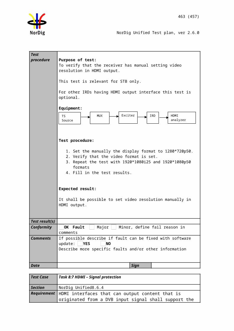
463 (457)
NorDig Unified Test plan, ver 2.6.0
IRD Profile(s) Basic, PVR, IRD, FETest procedure Purpose of test:
To verify that IRD sustains the ‘lipsync’ during playback and time-shift.
Equipment:IRD Under testLive stream or test network.
Test procedure:
The requirement in this test can be verified in parallel with the other 15:xx tasks. Subtitling synchronization is tested in tasks 15:49 and 15:50.
1. Play back recordings with different video, audio and subtitling components.2. Compare the relative delay of video and audio in playback with the live
content.3. Compare the relative delay of video and audio in timeshift with the live
content.4. Fill in the measurement record.
Expected results:The IRD recovers the ‘lipsync’ during normal playback mode and time-shift after 5s.
Test result(s) Measurement recordTest point Result OK/NOKVideo and audio components are played back in sync compared with the live content.Video and audio components are played back in timeshift in sync compared with the live content.Syncrhonization of videoand audio components is settled after changing from a trick mode to normal playback speed within 5 seconds.
Conformity OK Fault Major Minor, define fail reason in commentsComments If possible describe if fault can be fixed with software update: YES NO
Describe more specific faults and/or other information
Date Sign
Test Case Task 13:42 Full service playback – Dynamic update of PMT audio language
Section NorDig Unified 14.4.5Requirement During playback of recorded content the user shall be able to perform the same full ser-
vice selection as would have been possible during basic live viewing, such as select au-dio and/or subtitling language (if several components with same type are available), switch subtitling on or off, select audio format etc (with the limitation outlined in section 14.3.9). The basic live viewing refers to all streams excluding any HbbTV related streams.Dynamic changes in the services (such as a change of video aspect ratio or change of audio format) that occur during the recording shall be processed in the same way as during live viewing.During playback the NorDig PVR shall be able to set the same control as during live viewing, for example blanking of video and muting of sound depending on the event’s parental rating values (see 14.3.2) and signal protection (HDCP) on its digital output in-terface (see 9.9.4). For cases where the information is coming from EIT data (like parental rating descriptor), the playback shall at least act on the EIT signalling at the start of the recording (see 15.2.1). For the cases where the information is coming from
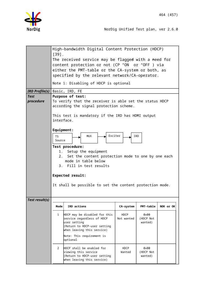
464 (457)
NorDig Unified Test plan, ver 2.6.0
PMT or the elementary streams (like signal protection and aspect ratio), the playback shall perform the same as live viewing and following any changes therein (i.e. PMT and elementary stream header information shall be stored and processed during playback).
IRD Profile(s) Basic, PVR, IRD, FETest procedure Purpose of test:
To verify that receiver that the Receiver handles the dynamic update of certain PSI/SI tables.
Test Equipment:
MUX1TS_id 1Network_id 1ON_id 1)
Service1SID 1100S_name Test11S_type 0x01PMT PID 1100V PID 1109 (MPEG2 SD)A PID 1108 (MPEG1L2)A PID 1107 (MPEG1L2)LCN 1 visible
Service2SID 1200S_name Test12S_type 0x16 or 0x19PMT PID 1200V PID 1209 (MPEG4 AVC)A PID 1208 (AC-3/E-AC-3 or HE-AAC)A PID 1207 (AC-33/E-AC-3 or HE-AAC)LCN 2 visible
Bouquet SIAll information in EIT.
Can be chosen depending of the distribution media.
1) ON_id (Original_network_id) can be chosen in range 0x0001-0xfe00 (operational network) and it shall be same for both muxes
Services may contain other components, e.g. teletext, subtitling and multiple additional audio tracks.
PMT of the test services shall be updated during the test so that audio components are added and removed in various combinations, e.g. by the following pattern:
Test procedure:1. Set the user preference for primary audio language to Lang1.2. Set the user preference for secondary audio language to other than Lang1 or
Lang2.3. Start recording.4. Select an another service.5. Update the PMT table of the service and add/remove audio component(s).6. Stop the recording.7. Set the user preference for primary audio language to other than Lang1 or
Lang2 and secondary audio language to Lang2.8. Play back the recording. 9. Fill in the measurement record.
Expected results:The receiver shall handle updates in PMT and record/playback according to the signaling. All decodable components in PMT have been recorded. User preference for primary/secondary audio language works correctly in playback.
Test result(s) Measurement record:
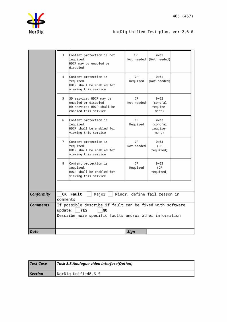
465 (457)
NorDig Unified Test plan, ver 2.6.0
Test point Result OK/NOKIRD records all decodable audio components in the serviceUser preference for primary/secondary audio language works correctly in playback.Audio track is selected for playback dynamically by the PMTPMT update and consequent audio track selection do not disturb the playback of other components.
Conformity OK Fault Major Minor, define fail reason in commentsComments If possible describe if fault can be fixed with software update: YES NO
Describe more specific faults and/or other information
Date Sign
Test Case Task 13:43 Full service playback – Dynamic update of PMT audio format
Section NorDig Unified 14.4.5Requirement During playback of recorded content the user shall be able to perform the same full ser-
vice selection as would have been possible during basic live viewing, such as select au-dio and/or subtitling language (if several components with same type are available), switch subtitling on or off, select audio format etc (with the limitation outlined in section 14.3.9). The basic live viewing refers to all streams excluding any HbbTV related streams.Dynamic changes in the services (such as a change of video aspect ratio or change of audio format) that occur during the recording shall be processed in the same way as during live viewing.During playback the NorDig PVR shall be able to set the same control as during live viewing, for example blanking of video and muting of sound depending on the event’s parental rating values (see 14.3.2) and signal protection (HDCP) on its digital output in-terface (see 9.9.4). For cases where the information is coming from EIT data (like parental rating descriptor), the playback shall at least act on the EIT signalling at the start of the recording (see 15.2.1). For the cases where the information is coming from PMT or the elementary streams (like signal protection and aspect ratio), the playback shall perform the same as live viewing and following any changes therein (i.e. PMT and elementary stream header information shall be stored and processed during playback).
IRD Profile(s) Basic, PVR, IRD, FETest procedure Purpose of test:
To verify that receiver that the Receiver handles the dynamic update of certain PSI/SI tables.
Test Equipment:
MPEG-2 source must have capability to support dynamic changes in audio components within service(s).In case of dual-channel audio the first language_descriptor definition corresponds physical left channel and second language_descriptor definition corresponds physical right channel.
This test task can be performed in parallel with Task 7:28 Dynamic changes in audio components.
Test procedure:
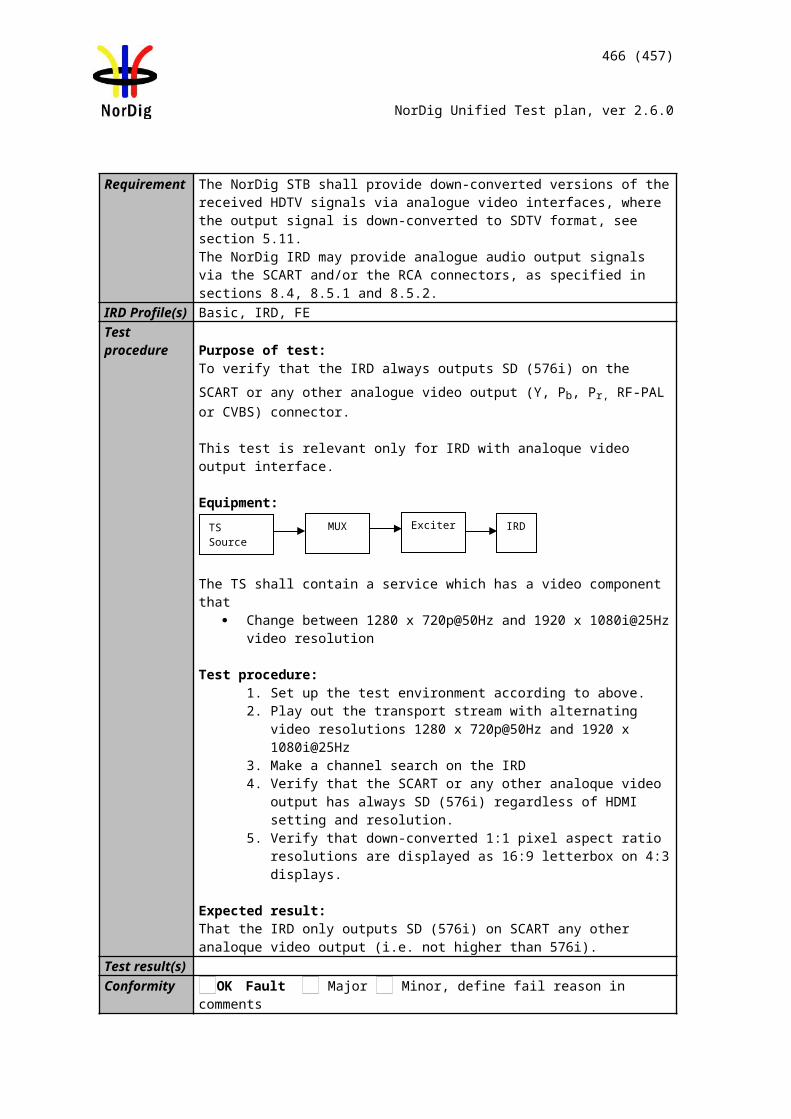
466 (457)
NorDig Unified Test plan, ver 2.6.0
1. Start recording.2. Use MPEG-2 source to generate dynamic changes in audio components as
listed in test results3. Play back the recording.4. Fill in the test results.
Expected result:
IRD is able to handle dynamic changes in audio components in playback.
Test result(s) Measurement record:Test point NOK or OKChange of number of audio channels within same audio codec (eg. AC-3 2.0 to AC-3 5.1 and vice versa.Change of bitrate for an audio component (eg. MPEG1-L2 bitrate from 192 kbps to 160 kbps)Change of audio PID value (any codec)Change from dual-channel audio into stereo audio and vice versaRemoval of selected audio component and using the next preferred oneAddition of one audio component with higher preferred user settingChange of the audio codec (eg. from MPEG1-L2 to AC-3Change of ISO 639-2 language for an audio component
Conformity OK Fault Major Minor, define fail reason in commentsComments If possible describe if fault can be fixed with software update: YES NO
Describe more specific faults and/or other information
Date Sign
Test Case Task 13:44 Full service playback – Dynamic update of PMT audio type
Section NorDig Unified 14.4.5Requirement During playback of recorded content the user shall be able to perform the same full ser-
vice selection as would have been possible during basic live viewing, such as select au-dio and/or subtitling language (if several components with same type are available), switch subtitling on or off, select audio format etc (with the limitation outlined in section 14.3.9). The basic live viewing refers to all streams excluding any HbbTV related streams.Dynamic changes in the services (such as a change of video aspect ratio or change of audio format) that occur during the recording shall be processed in the same way as during live viewing.During playback the NorDig PVR shall be able to set the same control as during live viewing, for example blanking of video and muting of sound depending on the event’s parental rating values (see 14.3.2) and signal protection (HDCP) on its digital output in-terface (see 9.9.4). For cases where the information is coming from EIT data (like parental rating descriptor), the playback shall at least act on the EIT signalling at the start of the recording (see 15.2.1). For the cases where the information is coming from PMT or the elementary streams (like signal protection and aspect ratio), the playback shall perform the same as live viewing and following any changes therein (i.e. PMT and elementary stream header information shall be stored and processed during playback).
IRD Profile(s) Basic, PVR, IRD, FETest procedure Purpose of test:
TS source MUX Exciter DVB receiver
467 (457)
NorDig Unified Test plan, ver 2.6.0
To verify that IRD records all audio tracks. To verify that IRD selects normal/undefined (0x00) audio component by default in playback.
Equipment:
The TS must contain two services with several audio components for the same language, audio formats and stream type but different audio types.
Suitable languages are Swedish, Finnish, Norwegian, Danish, Icelandic, Sami, Irish/Gaelic and English.
Audio type is signaled in PMT in one or all of the following descriptors:1) Supplementary_audio_descriptor for any stream type.2) AAC_descriptor for AAC audio.3) AC-3 descriptor for AC-3 audio.4) Enhanced AC-3 descriptor for E-AC-3 audio.5) ISO639_descriptor for any stream type.
IRD is assumed to prioritise the audio type signalization information in that order.
Audio format is stereo.
Stream type for all audio components is either MPEG-4 HE-AAC version 1 or E-AC-3 including metadata corresponding audio_type.
Service1 Service2 FrequencyMUXTS_id 1Network_id 1ON_id 1)
SID 1100S_name Test11PMT PID 1100V PID 1109A PID 1108
ISO639_language_code 2) Audio_type hearing impaired
A PID 1107 ISO639_language_code 2) Audio_type visual impaired commentary
A PID 1106 ISO639_language_code 2) Audio_type Normal/Undef
LCD 1 visible
SID 1200S_name Test12PMT PID 1200V PID 1209A PID 1208
ISO639_language_code 2) Audio_type hearing impaired
A PID 1207 ISO639_language_code 2) Audio_type visual impaired commentary
A PID 1206 ISO639_language_code 2) Audio_type Normal/Undef
LCD 2 visible
Can be chosen depending of the distribution media
1) ON_id (Original_network_id) can be chosen in range 0x0001-0xfe00 (operational network) and it shall be same for both muxes.
2) Language must the same for all audio components and it can be one of the swe/fin/nor/ice/dan/smi/gle/iri/eng/und
Test procedure:1. Start recording.2. Verify the receiver selects audio component which has normal/undefined audio
by default3. Verify user is able to select different audio components4. Play back the recording.5. Fill in the measurement record.
Expected result:
468 (457)
NorDig Unified Test plan, ver 2.6.0
IRD selects the audio component that is signalled as Normal/Undefined (0x00) by default when several audio components with the same language code, audio format and stream type but different audio type are available within one service.
The user shall be able to select between the different audio components during playback.
Test result(s) Measurement record:Test point Result OK/NOKIRD selects normal/undefined audio component by default in playbackAll audio components are recorded and selectable during playback
Conformity OK Fault Major Minor, define fail reason in commentsComments If possible describe if fault can be fixed with software update: YES NO
Describe more specific faults and/or other information
Date Sign
Test Case Task 13:45 Full service playback – Dynamic update of PMT subtitling language
Section NorDig Unified 14.4.5Requirement During playback of recorded content the user shall be able to perform the same full ser-
vice selection as would have been possible during basic live viewing, such as select au-dio and/or subtitling language (if several components with same type are available), switch subtitling on or off, select audio format etc (with the limitation outlined in section 14.3.9). The basic live viewing refers to all streams excluding any HbbTV related streams.Dynamic changes in the services (such as a change of video aspect ratio or change of audio format) that occur during the recording shall be processed in the same way as during live viewing.During playback the NorDig PVR shall be able to set the same control as during live viewing, for example blanking of video and muting of sound depending on the event’s parental rating values (see 14.3.2) and signal protection (HDCP) on its digital output in-terface (see 9.9.4). For cases where the information is coming from EIT data (like parental rating descriptor), the playback shall at least act on the EIT signalling at the start of the recording (see 15.2.1). For the cases where the information is coming from PMT or the elementary streams (like signal protection and aspect ratio), the playback shall perform the same as live viewing and following any changes therein (i.e. PMT and elementary stream header information shall be stored and processed during playback).
IRD Profile(s) Basic, PVR, IRD, FETest procedure Purpose of test:
To verify that receiver that the Receiver handles the dynamic update of certain PSI/SI tables.
Test Equipment:
MUX1TS_id 1Network_id 1ON_id 1)
Service1SID 1100S_name Test11S_type 0x01PMT PID 1100
Service2SID 1200S_name Test12S_type 0x16 or 0x19PMT PID 1200
Bouquet SIAll information in EIT.
Can be chosen depending of the distribution
469 (457)
NorDig Unified Test plan, ver 2.6.0
V PID 1109 (MPEG2 SD)A PID 1108 (MPEG1L2)S PID 1107 (DVB subtitling)S PID 1106 (DVB subtitling)LCN 1 visible
V PID 1209 (MPEG4 AVC)A PID 1208 S PID 1107 (DVB subtitling)S PID 1106 (DVB subtitling)LCN 2 visible
media.
MUX2TS_id 2Network_id 1ON_id 1)
Service3SID 2100S_name Test21S_type 0x01PMT PID 1100V PID 1109 (MPEG2 SD)A PID 1108 (MPEG1L2)S PID 1107 (TTX with multi-lingual subtitling)LCN 3 visible
Service4SID 2200S_name Test22S_type 0x16 or 0x19PMT PID 1200V PID 1209 (MPEG4 AVC)A PID 1208 S PID 1107 (TTX with multi-lingual subtitling)LCN 4 visible
. Can be chosen depending of the distribution media.
1) ON_id (Original_network_id) can be chosen in range 0x0001-0xfe00 (operational network) and it shall be same for both muxes
Services may contain other components, e.g. teletext, subtitling and multiple additional audio tracks.
PMT of the test services shall be updated during the test so that subtitling components are added and removed in various combinations, e.g. by the following pattern:
Test procedure:1. Set the user preference for primary subtitling language to Lang1.2. Set the user preference for secondary subtitling language to other than Lang1 or
Lang2.3. Start recording.4. Select an another service.5. Update the PMT table of the service and add/remove subtitling component(s).6. Stop the recording.7. Set the user preference for primary subtitling language to other than Lang1 or
Lang2 and secondary subtitling language to Lang2.8. Play back the recording. 9. Fill in the measurement record.
Expected results:The receiver shall handle updates in PMT and record/playback according to the signaling. All decodable components in PMT have been recorded. User preference for primary/secondary subtitling language works correctly in playback.
Test result(s) Measurement record:Test point Result OK/NOKIRD records all decodable subtitling components in the serviceUser preference for primary/secondary subtitling language works correctly in playback.Subtitling track is selected for playback dynamically by the PMTPMT update and consequent subtitling track selection do not disturb the playback of other components.
470 (457)
NorDig Unified Test plan, ver 2.6.0
Conformity OK Fault Major Minor, define fail reason in commentsComments If possible describe if fault can be fixed with software update: YES NO
Describe more specific faults and/or other information
Date Sign
Test Case Task 13:46 Full service playback – Subtitling for the hard-of-hearing
Section NorDig Unified 14.4.5Requirement During playback of recorded content the user shall be able to perform the same full ser-
vice selection as would have been possible during basic live viewing, such as select au-dio and/or subtitling language (if several components with same type are available), switch subtitling on or off, select audio format etc (with the limitation outlined in section 14.3.9). The basic live viewing refers to all streams excluding any HbbTV related streams.Dynamic changes in the services (such as a change of video aspect ratio or change of audio format) that occur during the recording shall be processed in the same way as during live viewing.During playback the NorDig PVR shall be able to set the same control as during live viewing, for example blanking of video and muting of sound depending on the event’s parental rating values (see 14.3.2) and signal protection (HDCP) on its digital output in-terface (see 9.9.4). For cases where the information is coming from EIT data (like parental rating descriptor), the playback shall at least act on the EIT signalling at the start of the recording (see 15.2.1). For the cases where the information is coming from PMT or the elementary streams (like signal protection and aspect ratio), the playback shall perform the same as live viewing and following any changes therein (i.e. PMT and elementary stream header information shall be stored and processed during playback).
IRD Profile(s) Basic, PVR, IRD, FETest procedure Purpose of test:
To verify that the IRD can handle signalisation and decoding of “hard of hearing” subtitling when they are broadcasted.or not during playback. To check that composition pages “normal” are chosen by default instead of “hard of hearing” in playback.
Support for ancillary pages is not tested.
Equipment:
A transport stream containing test services with DVB and EBU Teletext composition subtitling and “hard of hearing” components.
PMT of the test services shall be updated during the test so that subtitling components are added and removed in various combinations, e.g. by the following pattern:
Subtitling composition pages can be divided into two contents: “normal” or “hard of hearing”. Composition pages shall be enabled in mode “normal” by default. Subtitling ancillary pages can be broadcasted for more or less like a “raw data”.
471 (457)
NorDig Unified Test plan, ver 2.6.0
Ancillary pages shall be enabled by default.
Test procedure:1. Start recording.2. Update the PMT table of the recorded service and add/remove normal and
hard-of-hearing subtitling component(s).3. Stop the recording.4. Enable ’hard-of-hearing’ subtitling in the user preferences.5. Play back the recording.6. Fill in the measurement record.
Expected result: Hard of hearing content of the DVB and EBU Teletext subtitling is recorded, handled, displayed and decoded correctly in playback.
Test result(s) Measurement record:Test point Result OK/NOKIRD records all decodable subtitling components in the serviceSubtitling track is selected for playback dynamically according to the PMTHard-of-hearing subtitles are displayed automatically only if selected as the user preferencePMT update and consequent subtitling track selection do not disturb the playback of other components
Conformity OK Fault Major Minor, define fail reason in commentsComments If possible describe if fault can be fixed with software update: YES NO
Describe more specific faults and/or other information
Date Sign
Test Case Task 13:47 Full service playback – Dynamic update of PMT subtitling type
Section NorDig Unified 14.4.5Requirement During playback of recorded content the user shall be able to perform the same full ser-
vice selection as would have been possible during basic live viewing, such as select au-dio and/or subtitling language (if several components with same type are available), switch subtitling on or off, select audio format etc (with the limitation outlined in section 14.3.9). The basic live viewing refers to all streams excluding any HbbTV related streams.Dynamic changes in the services (such as a change of video aspect ratio or change of audio format) that occur during the recording shall be processed in the same way as during live viewing.During playback the NorDig PVR shall be able to set the same control as during live viewing, for example blanking of video and muting of sound depending on the event’s parental rating values (see 14.3.2) and signal protection (HDCP) on its digital output in-terface (see 9.9.4). For cases where the information is coming from EIT data (like parental rating descriptor), the playback shall at least act on the EIT signalling at the start of the recording (see 15.2.1). For the cases where the information is coming from PMT or the elementary streams (like signal protection and aspect ratio), the playback shall perform the same as live viewing and following any changes therein (i.e. PMT and elementary stream header information shall be stored and processed during playback).
IRD Profile(s) Basic, PVR, IRD, FETest procedure Purpose of test:
To verify that the IRD prioritizes DVB subtitling over TTX subtitling in playback.
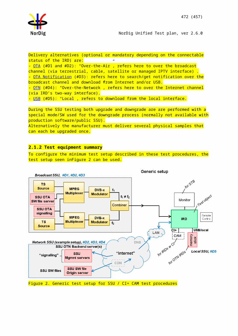
472 (457)
NorDig Unified Test plan, ver 2.6.0
Equipment:
A transport stream containing test services with DVB and EBU Teletext composition subtitling.
PMT of a test service shall be updated during the test so that subtitling components are added and removed in various combinations, e.g. by the following pattern:
Test procedure:1. Start recording.2. Update the PMT table of the recorded service and add/remove DVB and EBU
Teletext subtitling component(s).3. Stop the recording.4. Start another recording.5. Observe 6. Play back the recordings.7. Fill in the measurement record.
Expected result: DVB and EBU Teletext subtitling is recorded, handled, displayed and decoded correctly in playback.
Test result(s) Measurement record:Test point Result OK/NOKIRD records all decodable subtitling components in the serviceSubtitling track is selected for playback dynamically according to the PMTDVB subtitles are prioritized over EBU Teletext subtitles in playbackTeletext subtitles and DVB subtitles are not displayed simultaneously.
Conformity OK Fault Major Minor, define fail reason in commentsComments If possible describe if fault can be fixed with software update: YES NO
Describe more specific faults and/or other information
Date Sign
Test Case Task 13:48 Full service playback – Subtitling syncrhonization
Section NorDig Unified 14.4.5Requirement During playback of recorded content the user shall be able to perform the same full ser-
vice selection as would have been possible during basic live viewing, such as select au-dio and/or subtitling language (if several components with same type are available), switch subtitling on or off, select audio format etc (with the limitation outlined in section 14.3.9). The basic live viewing refers to all streams excluding any HbbTV related streams.Dynamic changes in the services (such as a change of video aspect ratio or
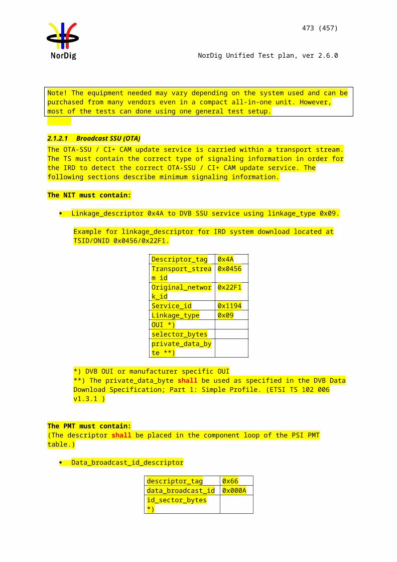
473 (457)
NorDig Unified Test plan, ver 2.6.0
change of audio format) that occur during the recording shall be processed in the same way as during live viewing.During playback the NorDig PVR shall be able to set the same control as during live viewing, for example blanking of video and muting of sound depending on the event’s parental rating values (see 14.3.2) and signal protection (HDCP) on its digital output in-terface (see 9.9.4). For cases where the information is coming from EIT data (like parental rating descriptor), the playback shall at least act on the EIT signalling at the start of the recording (see 15.2.1). For the cases where the information is coming from PMT or the elementary streams (like signal protection and aspect ratio), the playback shall perform the same as live viewing and following any changes therein (i.e. PMT and elementary stream header information shall be stored and processed during playback).
IRD Profile(s) Basic, PVR, IRD, FETest procedure Purpose of test:
To verify that the IRD sustains the subtitling synchronization in playback.Equipment:
A transport stream containing test services with DVB and EBU Teletext composition subtitling.
Test procedure:1. Start recording.2. Record the content for at least 30 minutes.3. Stop the recording.4. Play back the recording.5. Observe the relative synchronization of subtitling.6. Fill in the measurement record.
Expected result: DVB and EBU Teletext subtitling is recorded, handled, displayed and decoded correctly in playback.
Test result(s) Measurement record:Test point Result OK/NOKDVB subtitling on a SD service is displayed synchronized in playback compared to the live streamDVB subtitling on a HD service is displayed synchronized in playback compared to the live streamEBU teletext subtitling on a SD service is displayed synchronized in playback compared to the live streamEBU teletext subtitling on a HD service is displayed synchronized in playback compared to the live stream
Conformity OK Fault Major Minor, define fail reason in commentsComments If possible describe if fault can be fixed with software update: YES NO
Describe more specific faults and/or other information
Date Sign
Test Case Task 13:49 Full service playback – Subtitling synchronization in time-shift
Section NorDig Unified 14.4.5
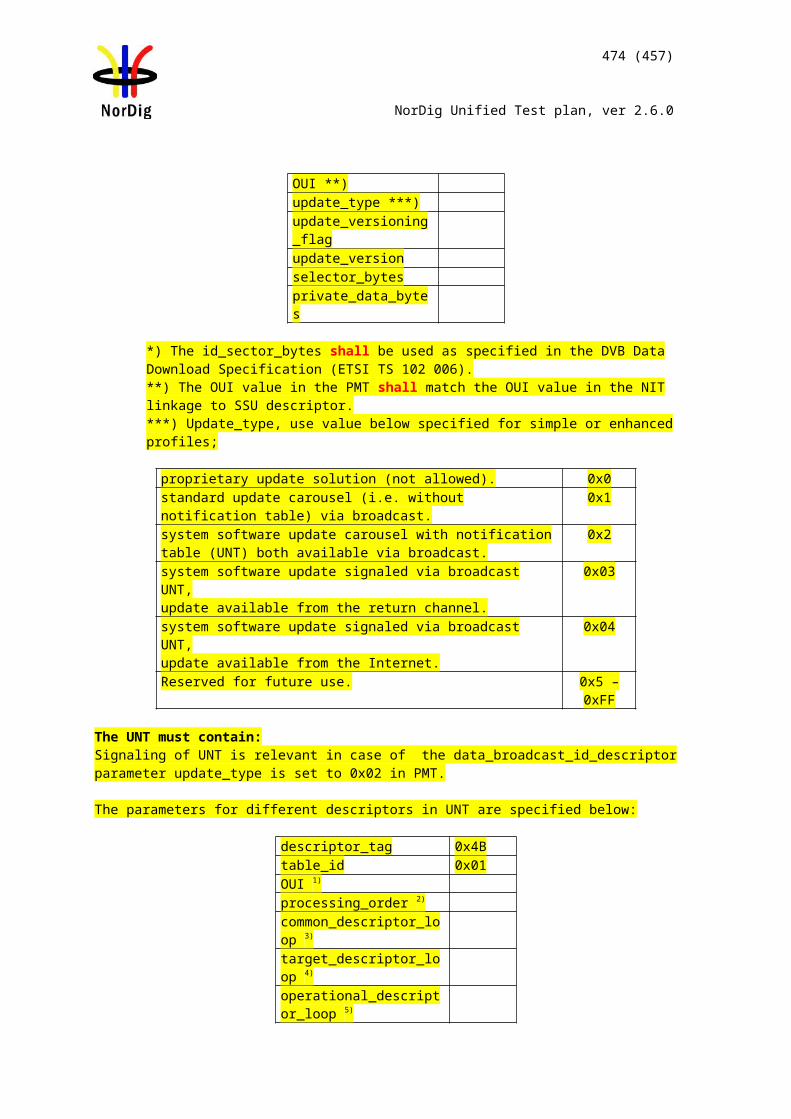
474 (457)
NorDig Unified Test plan, ver 2.6.0
Requirement During playback of recorded content the user shall be able to perform the same full ser-vice selection as would have been possible during basic live viewing, such as select au-dio and/or subtitling language (if several components with same type are available), switch subtitling on or off, select audio format etc (with the limitation outlined in section 14.3.9). The basic live viewing refers to all streams excluding any HbbTV related streams.Dynamic changes in the services (such as a change of video aspect ratio or change of audio format) that occur during the recording shall be processed in the same way as during live viewing.During playback the NorDig PVR shall be able to set the same control as during live viewing, for example blanking of video and muting of sound depending on the event’s parental rating values (see 14.3.2) and signal protection (HDCP) on its digital output in-terface (see 9.9.4). For cases where the information is coming from EIT data (like parental rating descriptor), the playback shall at least act on the EIT signalling at the start of the recording (see 15.2.1). For the cases where the information is coming from PMT or the elementary streams (like signal protection and aspect ratio), the playback shall perform the same as live viewing and following any changes therein (i.e. PMT and elementary stream header information shall be stored and processed during playback).
IRD Profile(s) Basic, PVR, IRD, FETest procedure Purpose of test:
To verify that IRD sustains the subtitling synchronization in time-shift.Equipment:
A transport stream containing test services with DVB and EBU Teletext composition subtitling.
Test procedure:1. Enable timeshift.2. View the service delayed.3. Observe the relative synchronization of subtitling for at least 15 minutes.4. Fill in the measurement record.
Expected result: DVB and EBU Teletext subtitling is recorded, handled, displayed and decoded correctly in timeshift.
Test result(s) Measurement record:Test point Result OK/NOKDVB subtitling on a SD service is displayed synchronized in timeshift mode compared to the live streamDVB subtitling on a HD service is displayed synchronized in timeshift mode compared to the live streamEBU teletext subtitling on a SD service is displayed synchronized in timeshift mode compared to the live streamEBU teletext subtitling on a HD service is displayed synchronized in timeshift mode compared to the live stream
Conformity OK Fault Major Minor, define fail reason in commentsComments If possible describe if fault can be fixed with software update: YES NO
Describe more specific faults and/or other information
Date Sign
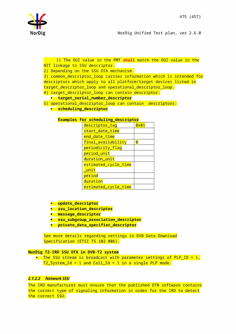
475 (457)
NorDig Unified Test plan, ver 2.6.0
Test Case Task 13:50 Full service playback – Dynamic update of PMT video and audio PIDs
Section NorDig Unified 14.4.5Requirement During playback of recorded content the user shall be able to perform the same full ser-
vice selection as would have been possible during basic live viewing, such as select au-dio and/or subtitling language (if several components with same type are available), switch subtitling on or off, select audio format etc (with the limitation outlined in section 14.3.9). The basic live viewing refers to all streams excluding any HbbTV related streams.Dynamic changes in the services (such as a change of video aspect ratio or change of audio format) that occur during the recording shall be processed in the same way as during live viewing.During playback the NorDig PVR shall be able to set the same control as during live viewing, for example blanking of video and muting of sound depending on the event’s parental rating values (see 14.3.2) and signal protection (HDCP) on its digital output in-terface (see 9.9.4). For cases where the information is coming from EIT data (like parental rating descriptor), the playback shall at least act on the EIT signalling at the start of the recording (see 15.2.1). For the cases where the information is coming from PMT or the elementary streams (like signal protection and aspect ratio), the playback shall perform the same as live viewing and following any changes therein (i.e. PMT and elementary stream header information shall be stored and processed during playback).
IRD Profile(s) Basic, PVR, IRD, FETest procedure Purpose of test:
To verify the IRD handles dynamic PMT updates in playback.
Test equipment:
Service1 Service2 FrequencyMUX1TS_id 1Network_id 1ON_id 1)
SID 1100S_name Test11S_type 0x01, 0x16 or 0x19PMT PID 1100V PID 1109 incl PCRA PID 1108Teletext PID 1107DVB Subt PID 1106LCN1visible
SID 1200S_name Test12S_type 0x01, 0x16 or 0x19PMT PID 1200V PID 1209 incl PCRA PID 1208Teletext PID 1207DVB Subt PID 1106LCN 2 visible
Can be chosen depending of the distribution media
1) ON_id (Original_network_id) can be chosen in range 0x0001-0xfe00 (operational network)
Sometimes broadcaster may drop, add or change the content of the PID. If this happens, the PMT is updated by changing the version_id.
This task can be performed in parallel with Task 11:26 Dynamic update of PMT PID values.
Test procedure:
1. Drop all PIDs on Service1 on MUX1.2. Select Service1.
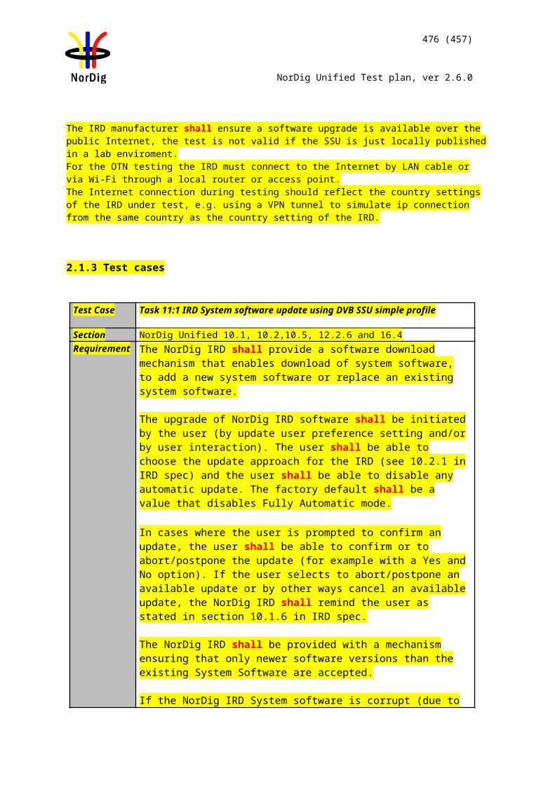
476 (457)
NorDig Unified Test plan, ver 2.6.0
3. Start recording.4. Add PIDs in following order:
a. Video PID 1109b. Audio PID 1108c. Teletext PID1107d. DVB subtitling PID 1106
5. Verify that the service is decoded correctly by watching the video, listening the audio and reading the teletext, teletext subtitling and DVB subtitling
6. Change the following PID values:a. Video PID 1109 to 1103b. Audio PID 1108 to 1102
7. Stop recording.8. Play back the recording.9. Fill in the measurement record.
Expected result:After addition or change of the PIDs, all the component in the service are recorded and played back correctly.
Change of PID values maintains the service decoding. Test result(s) Measurement record:
Test point Result OK/NOKIRD handles PMT updates and records all components in PMTIRD handles PID changes during the recording
Conformity OK Fault Major Minor, define fail reason in commentsComments If possible describe if fault can be fixed with software update: YES NO
Describe more specific faults and/or other information
Date Sign
Test Case Task 13:51 Full service playback – Dynamic update of video aspect ratio
Section NorDig Unified 14.4.5Requirement During playback of recorded content the user shall be able to perform the same full ser-
vice selection as would have been possible during basic live viewing, such as select au-dio and/or subtitling language (if several components with same type are available), switch subtitling on or off, select audio format etc (with the limitation outlined in section 14.3.9). The basic live viewing refers to all streams excluding any HbbTV related streams.Dynamic changes in the services (such as a change of video aspect ratio or change of audio format) that occur during the recording shall be processed in the same way as during live viewing.During playback the NorDig PVR shall be able to set the same control as during live viewing, for example blanking of video and muting of sound depending on the event’s parental rating values (see 14.3.2) and signal protection (HDCP) on its digital output in-terface (see 9.9.4). For cases where the information is coming from EIT data (like parental rating descriptor), the playback shall at least act on the EIT signalling at the start of the recording (see 15.2.1). For the cases where the information is coming from PMT or the elementary streams (like signal protection and aspect ratio), the playback shall perform the same as live viewing and following any changes therein (i.e. PMT and elementary stream header information shall be stored and processed during playback).
IRD Profile(s) Basic, PVR, IRD, FETest procedure Purpose of test:
To verify that receiver that the Receiver handles the dynamic update of certain PSI/SI tables.
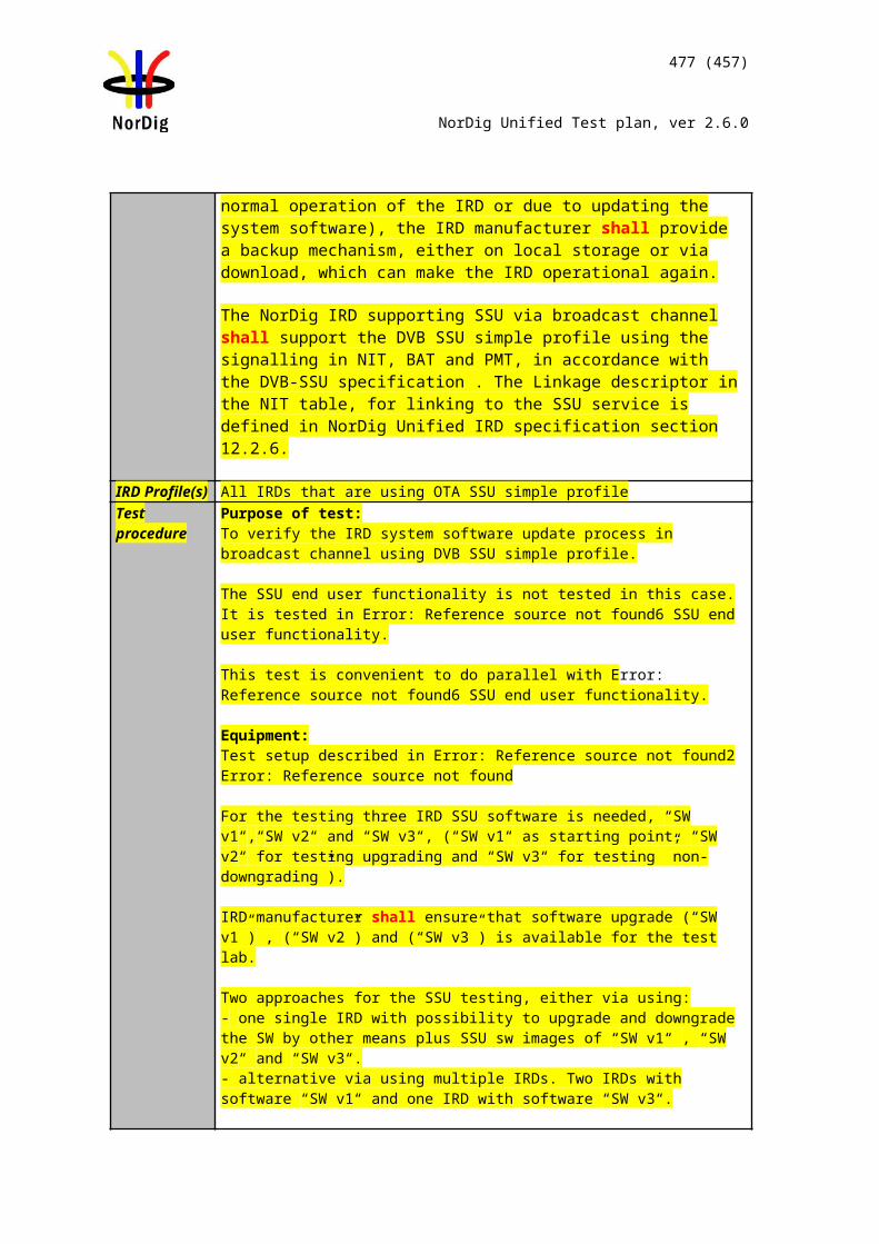
477 (457)
NorDig Unified Test plan, ver 2.6.0
Test Equipment:
Test strem or live signal where aspect ratio changes dynamically between 16:9 and 4:3:
MPEG-4 AVC HP@L3 576i 25Hz MPEG-4 AVC HP@L4 720p 50Hz MPEG-4 AVC HP@L4 1080i 25Hz MPEG-2 MP@ML 576i 25Hz
Test procedure:
1. Start recording.2. Update the aspect ratio of the video stream.3. Stop recording4. Play back the recording.5. Verify that the IRD reacts to the aspect ratio change correctly6. Fill in the measurement record.
Expected results:The receiver shall handle updates in PMT and record/playback according to the signaling.
Test result(s) Test Point Result OK/NOKMPEG-4 AVC HP@L3 576i25 16:9 to 4:3MPEG-4 AVC HP@L3 576i25 4:3 to 16:9MPEG-4 AVC HP@L4 720p50 16:9 to 4:3MPEG-4 AVC HP@L4 720p50 4:3 to 16:9MPEG-4 AVC HP@L4 1080i25 16:9 to 4:3MPEG-4 AVC HP@L4 1080i25 4:3 to 16:9 MPEG-2 MP@ML 576i25 16:9 to 4:3MPEG-2 MP@ML 576i25 4:3 to 16:9
Conformity OK Fault Major Minor, define fail reason in commentsComments If possible describe if fault can be fixed with software update: YES NO
Describe more specific faults and/or other information
Date Sign
Test Case Task 13:52 Full service playback – Dynamic update of PMT CA status
Section NorDig Unified 14.4.5Requirement During playback of recorded content the user shall be able to perform the same full ser-
vice selection as would have been possible during basic live viewing, such as select au-dio and/or subtitling language (if several components with same type are available), switch subtitling on or off, select audio format etc (with the limitation outlined in section 14.3.9). The basic live viewing refers to all streams excluding any HbbTV related streams.Dynamic changes in the services (such as a change of video aspect ratio or change of audio format) that occur during the recording shall be processed in the same way as during live viewing.
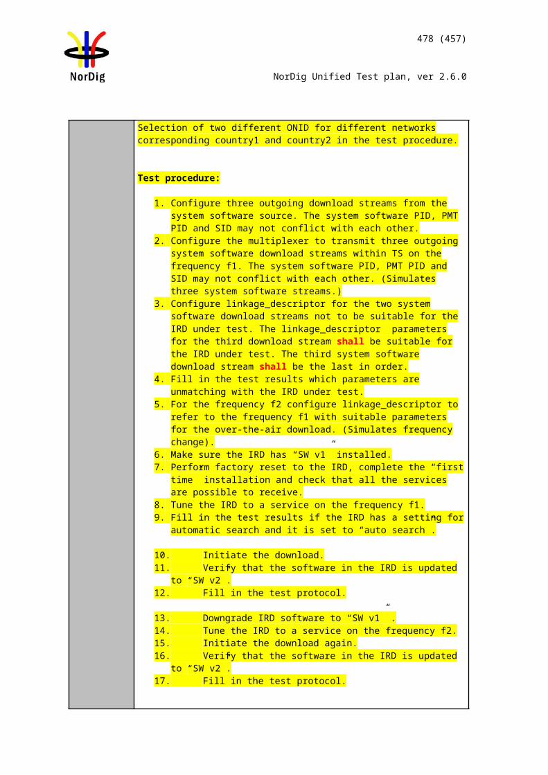
478 (457)
NorDig Unified Test plan, ver 2.6.0
During playback the NorDig PVR shall be able to set the same control as during live viewing, for example blanking of video and muting of sound depending on the event’s parental rating values (see 14.3.2) and signal protection (HDCP) on its digital output in-terface (see 9.9.4). For cases where the information is coming from EIT data (like parental rating descriptor), the playback shall at least act on the EIT signalling at the start of the recording (see 15.2.1). For the cases where the information is coming from PMT or the elementary streams (like signal protection and aspect ratio), the playback shall perform the same as live viewing and following any changes therein (i.e. PMT and elementary stream header information shall be stored and processed during playback).
IRD Profile(s) Basic, PVR, IRD, FETest procedure Purpose of test:
To verify that receiver that the Receiver handles the dynamic update of certain PSI/SI tables.
Test Equipment:
Live stream or test network with a service that changes from free to scrambled.
Test procedure:1. Tune to an unencrypted service that changes from free to scrambled.2. Insert to the IRD a smartcard (and CAM if applicable) with subscription to the
service.3. Start recording over the CA status change.4. Verify that IRD continues recording regardless of the CA status change.5. Play back the service with proper CA card.6. Verify that the IRD is able to play back the recording.
Expected results:The receiver shall handle updates in PMT and record/playback according to the signaling.
Test result(s)Conformity OK Fault Major Minor, define fail reason in commentsComments If possible describe if fault can be fixed with software update: YES NO
Describe more specific faults and/or other information
Date Sign
Test Case Task 13:53 Dynamic changes in video stream in playback
Section NorDig Unified 14.4.5Requirement During playback the NorDig PVR shall be able to set the same control as during live
viewing, for example blanking of video and muting of sound depending on the event’s parental rating values (see 14.3.2) and signal protection (HDCP) on its digital output interface (see 9.9.4). For cases where the information is coming from EIT data (like parental rating descriptor), the playback shall at least act on the EIT signalling at the start of the recording (see 15.2.1). For the cases where the information is coming from PMT or the elementary streams (like signal protection and aspect ratio), the playback shall perform the same as live viewing and following any changes therein (i.e. PMT and elementary stream header information shall be stored and processed during playback).
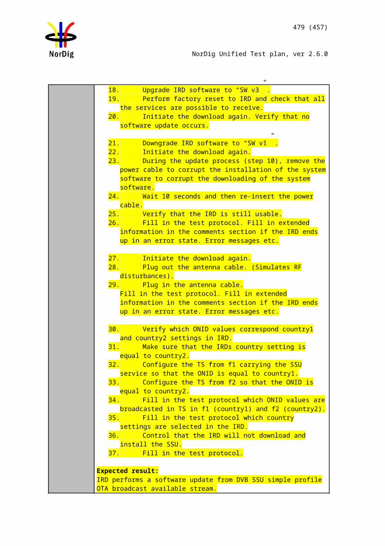
Source MUX Exciter DVB receiver
Monitor
479 (457)
NorDig Unified Test plan, ver 2.6.0
IRD Profile(s) Basic, PVR, IRD, FETest procedure Purpose of test:
To verify that the receiver is able to handle dynamic changes in transmission between different video modes while recording.
Equipment:
This task can be performed in parallel with Task 6:5 Video Decoder - Dynamic changesin video stream.
Transport stream containing services with following video content and transitions between them:
MPEG-4 AVC HP@L3 576i 25Hz MPEG-4 AVC HP@L4 720p 50Hz MPEG-4 AVC HP@L4 1080i 25Hz MPEG-2 MP@ML 576i 25Hz
Test procedure:
1. Start recording.2. Perform the required video format transitions.3. Stop recording.4. Verify that changes between modes are happening correctly on playback.5. Fill in the measurement record.
Expected result:
The IRD is able to handle video mode changes during recording and playback.
Test result(s) Measurement record:From To OK/NOKMPEG-4 AVC HP@L3 576i 25Hz
MPEG-4 AVC HP@L4 720p 50Hz
MPEG-4 AVC HP@L4 720p 50Hz
MPEG-4 AVC HP@L3 576i 25Hz
MPEG-4 AVC HP@L4 720p 50Hz
MPEG-4 AVC HP@L4 1080i 25Hz
MPEG-4 AVC HP@L4 1080i 25Hz
MPEG-4 AVC HP@L4 720p 50Hz
MPEG-4 AVC HP@L4 1080i 25Hz
MPEG-4 AVC HP@L3 576i 25Hz
MPEG-4 AVC HP@L3 576i 25Hz
MPEG-4 AVC HP@L4 1080i 25Hz
MPEG-2 MP@ML 576i 25Hz
MPEG-4 AVC HP@L4 720p 50Hz
MPEG-4 AVC HP@L4 720p 50Hz
MPEG-2 MP@ML 576i 25Hz
Conformity OK Fault Major Minor, define fail reason in commentsComments If possible describe if fault can be fixed with software update: YES NO
Describe more specific faults and/or other information
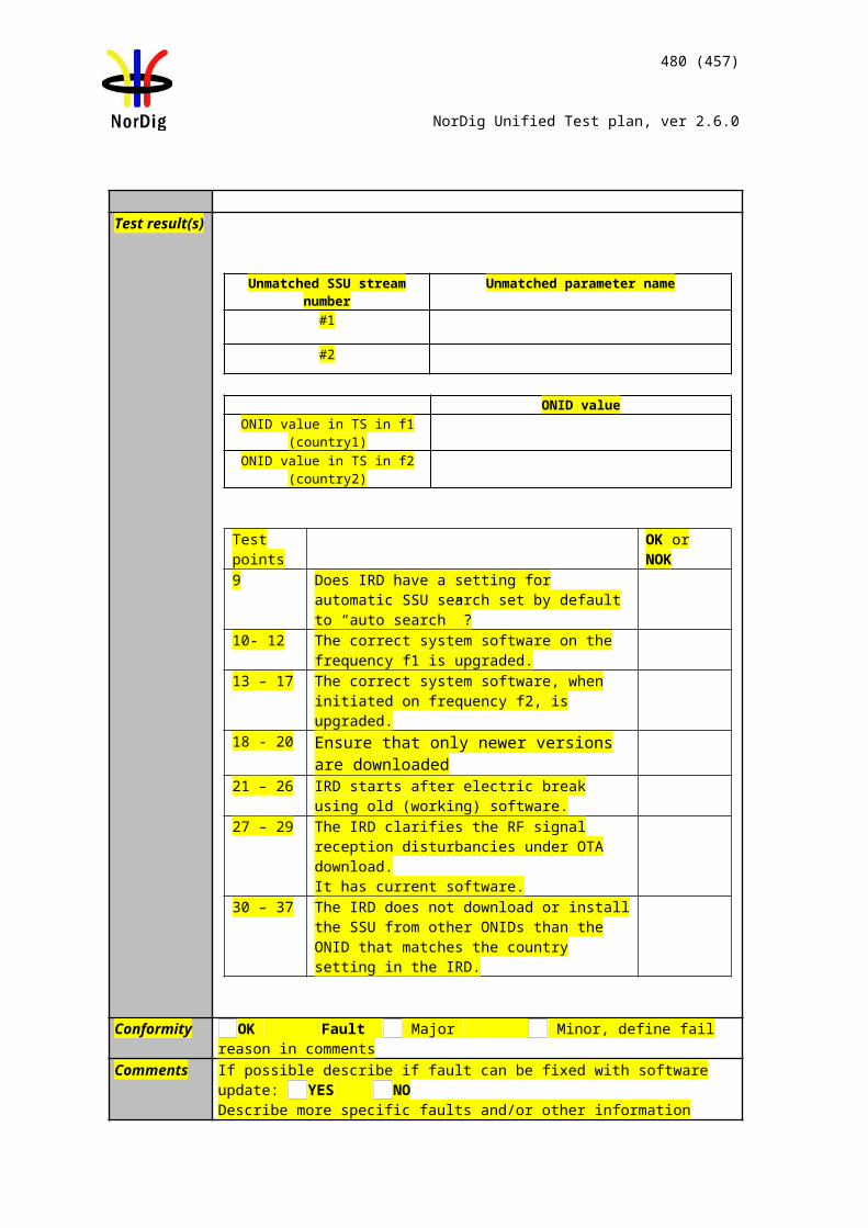
480 (457)
NorDig Unified Test plan, ver 2.6.0
Date Sign
Task 13:54 Parental lock during playback
Section NorDig Unified 14.4.5Requirement During playback the NorDig PVR shall be able to set the same control as during live
viewing, for example blanking of video and muting of sound depending on the event’s parental rating values (see 14.3.2) and signal protection (HDCP) on its digital output interface (see 9.9.4). For cases where the information is coming from EIT data (like parental rating descriptor), the playback shall at least act on the EIT signalling at the start of the recording (see 15.2.1). For the cases where the information is coming from PMT or the elementary streams (like signal protection and aspect ratio), the playback shall perform the same as live viewing and following any changes therein (i.e. PMT and elementary stream header information shall be stored and processed during playback).
IRD Profile(s) Basic, PVR, IRD, FETest procedure Purpose of test:
To verify that the IRD reacts to dynamic changes in EIT parental rating value also for the recordings.
Equipment:This task can be performed in parallel with Task 11:21 Dynamic update of EIT actual/other p/f parental_rating_descriptor
Test procedure:
1. Choose an arbitrary parental rating value N.
2. Set the parental lock value as “disabled” or over N.
3. Initiate an OTR over consecutive events having the parental ratings as follows:
No rating Rating value N No rating Rating Value M < N No rating
4. Stop the recording.
5. Change the IRD parental lock value between M and N.
6. Play back the recording.
7. Stop the playback.
8. Disable the parental lock .
9. Play back the recording again.
10. Set the parental lock value below M.
11. Repeat the steps 2 – 9
Expected results:The IRD stores the EIT parental_rating_descriptor value and reacts accordingly during the playback.
Test result(s) Measurement recordTest point Result OK/NOK
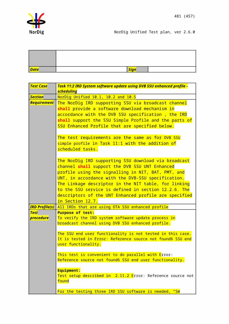
481 (457)
NorDig Unified Test plan, ver 2.6.0
IRD invokes parental lock for a recording that has higher rating in parental_rating_descriptor than the current user preference.Parental lock is not displayed if user preference is higher than the highest rating value in the recording.Parental lock is not displayed if user preference is disabled.EIT Parental rating is interpreted dynamically (optional)
Conformity OK Fault Major Minor, define fail reason in commentsComments If possible describe if fault can be fixed with software update: YES NO
Describe more specific faults and/or other information
Date Sign
Task 13:55 Maintaining scheduled recordings after network update
Section NorDig Unified 14.3.2Requirement The NorDig PVR shall make it possible for the user to select individual events and
series to be recordedfrom the ESG or EPG display (based on information from EIT data).
IRD Profile(s) Basic, PVR, IRD, FETest procedure Purpose of test:
To verify that network changes do not affect the recording schedule.
Equipment:This task can be performed in parallel with Task 12:16 Quasi-static update of service list– services moved between different transport streams
Test procedure:
1. Set up the Task 12:16 initial situation.
2. Schedule a recording for service ‘Test12’ after the time event when the IRD quasi-statically reacts to the network changes.
(Example: If the IRD reacts to the network changes always at 03:00, schedule the recording to happen after that time)
3. Perform the network change according to Task 12:16.
4. Make sure that automatic service list update is initiated.
5. Set the IRD to standby.
6. Verify that the IRD performs the recording correctly as scheduled in step 2.
Expected results:Scheduled recordings are not affected by network changes.
Test result(s)Conformity OK Fault Major Minor, define fail reason in commentsComments If possible describe if fault can be fixed with software update: YES NO
Describe more specific faults and/or other information
Date Sign
Task 13:56 User actions disturbing the recording
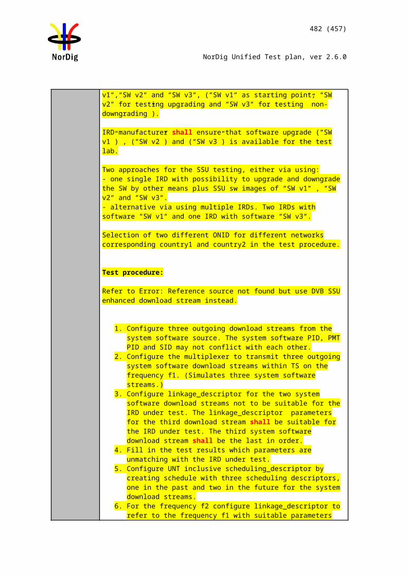
482 (457)
NorDig Unified Test plan, ver 2.6.0
Section NorDig Unified 14.3.2Requirement During playback the NorDig PVR shall be able to set the same control as during live
viewing, for example blanking of video and muting of sound depending on the event’s parental rating values (see 14.3.2) and signal protection (HDCP) on its digital output interface (see 9.9.4). For cases where the information is coming from EIT data (like parental rating descriptor), the playback shall at least act on the EIT signalling at the start of the recording (see 15.2.1). For the cases where the information is coming from PMT or the elementary streams (like signal protection and aspect ratio), the playback shall perform the same as live viewing and following any changes therein (i.e. PMT and elementary stream header information shall be stored and processed during playback).
IRD Profile(s) Basic, PVR, IRD, FETest procedure Purpose of test:
To verify that the PVR IRD is able to handle reception errors gracefully.
Equipment:Test network
Test procedure:1. Initiate a recording.2. Set the IRD to standby for a short time, e.g. 1 minute.3. Wake up the IRD. 4. Set the IRD to standby for a longer period of time, e.g. 30 minutes.5. Wake up the IRD.6. Shut down and re-start the HDMI sink (Not applicable for iDTVs).7. Stop the recording. 8. Initiate a new recording.9. Power cycle the IRD. 10. Stop the recording, if it is still active.11. Fill in the measurement record.
Expected results:IRD is able to handle the disturbances in the operational environment gracefully.
Test result(s) Measurement recordTest point Result OK/NOKIRD continues an ongoing recording in stand-by mode HDCP connection status does not disturb the recording.IRD returns back to the originating power state after a power cycle.IRD indicates the recording is incomplete.
Conformity OK Fault Major Minor, define fail reason in commentsComments If possible describe if fault can be fixed with software update: YES NO
Describe more specific faults and/or other information
Date Sign
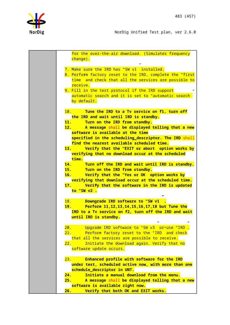
483 (457)
NorDig Unified Test plan, ver 2.6.0
2.15 Task 16: IRD System Software and API
2.15.1 Introduction
This section specifies the test plans related to the NorDig HbbTV IRD and Nordig HEVC iDTV configurations. Nordig Basic TV IRD System software tests are defined elsewhere in this document.
Verified passing of the latest HbbTV official test suite [3] is a mandatory requirement for all NorDig Hybrid HbbTV IRD profiles and Nordig HEVC iDTV configurations. The implementation of the HbbTV in the NorDig Hybrid HbbTV IRD or HEVC iDTV shall be verified by the manufacturer, i.e. the verification testing is based on self-testing by the manufacturer unless otherwise specified by the relevant network/Operator.
NorDig broadcast member may request to get a copy of the manufacture’s HbbTV Verification Test report with test results, before approving a Hybrid IRD on the market.
Informative: The official HbbTV Test suite of the HbbTV Association (http://hbbtv.org) consists of a huge number of test cases, some of which the HbbTV Association has defined as mandatory and some as optional. The optional cases can be referred to as ”additional test material”. Some of these optional test cases have been contributed by NorDig and some by other testing regimes.
NorDig mandates that NorDig Hybrid IRDs shall pass: - all test cases that are included in the latest HbbTV test suite and which HbbTV organisation has defined
as mandatory- a number of additional test cases that are included in the latest HbbTV standard test suite but which
HbbTV Association has defined as optional/additional test material. These test cases are included in the list of Test Cases below. (Please Note that these test cases might be optional in standard HbbTV Test Suite and in other markets)
- a number of NorDig defined HbbTV test cases which are only included in this NorDig Test Plan.
Nordig mandates that Nordig HbbTV IRDs and HEVC iDTVs, i..e. devices supporting HbbTV standard version 2.0.1 or 2.0.2 (determined by the information included in the IRD’s user agent as reported by the browser) shall pass
- all test cases in the official HbbTV DASH-DRM Reference application [https://refapp.hbbtv.org] relevant to the DRM schemes the IRD supports (Playready / Marlin / Clearkey) and/or the operator requires
o Test cases include out-of-band subtitles, in-band subtitles, in-band events, advert insertion, multi-audio DASH and Live DASH.
- all test cases in the official HbbTV Test Suite related to out-of-band subtitles, in-band subtitles and advert insertion. Detailed test list is included in chapter 2.6.12
The current HbbTV Test Suite is available from HbbTV association and it provides a set of test material to test HbbTV device implementations. It is suitable for manufacturers of devices, including hardware and software components implementing the HbbTV specification. For information on how to obtain the HbbTV Test Suite, device manufacturer should refer to http://hbbtv.org/resource-library/#testing-information-and-support .
NorDig has contributed into HbbTV organisation with all our NorDig-developed test cases (including test material) and these are available from the HbbTV organisation’s Test Repository as ”additional test material”. It is recommended to use this alternative. For any party who is unable to access the HbbTV Test Repository to obtain the Nordig HbbTV Test Materials, these can be obtained via the Nordig website (http://www.nordig.org) as well, free of charge, but subject to accepting the Nordig Test Suite Licence Agreement (available from the Nordig website). The approved Nordig HbbTV Test Suite is identical on both sources.
Running the test cases requires access to the HbbTV Minimum Test Harness or, a commercial harness. or the Nordig Helper App. The latter is a tool for running the tests and obtaining the results in a meaningful
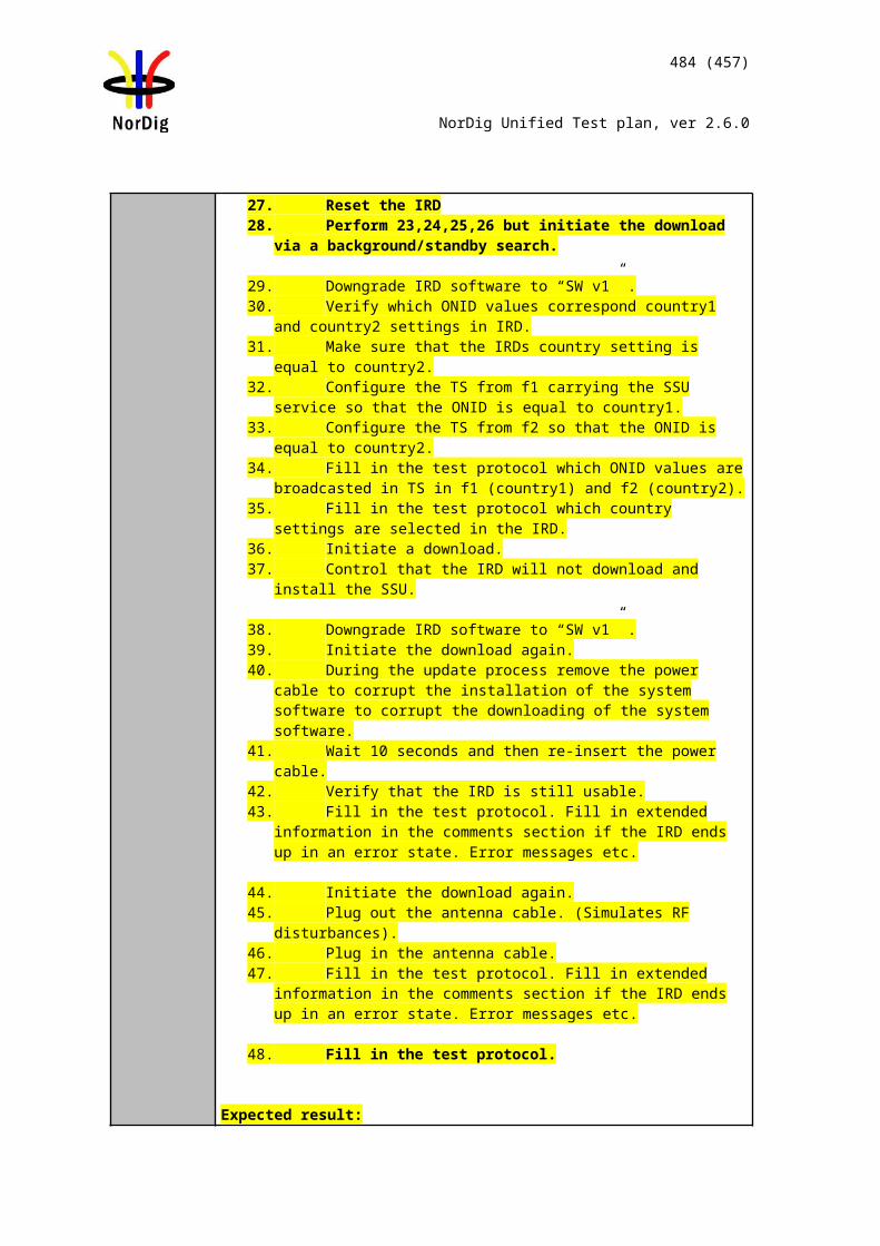
484 (457)
NorDig Unified Test plan, ver 2.6.0
way. Note that the Nordig Helper App enables only the tests designated with «org.nordig» domain to be run.
Please note that currently the Minimum Test Harness is able to run only the tests that are approved to the official HbbTV Test Suite. CI+ test cases are also mandatory to pass as they are approved to the official HbbTV Test Suite. To run the CI+ tests, a test CAM which is compatible with the test harness will be needed. This is likely to either be available through the provider of your commercial test harness, or in the case of the Minimum Test Harness from Eurofins Digital Testing. Please contact [email protected] for assistance in running the CI+ tests in the Minimum Test Harness. The Nordig HbbTV Test Suite includes the materials for tasks 16:1 to 16:59.
National testing regimes, operators and broadcasters define the final requirements for any regional certification process, and these might include additional test suites and test cases (for example DRM tests). Additional test materials are available from the latest release of the HbbTV Test Suite or from the entity organizing the testing regime. The chapter and table 2.16.2. define the test tasks that are by default mandatory to pass to pass the Nordig Test Suite part of any national regime.
Development of the Nordig Test cases is a continuous process and can be tracked in HbbTV Redmine system under the «Nordig API» -group. Redmine system can be reached from https://hbbtv.org/redmine/projects/nordig-api-group.
Detailed test task procedures are not repeated here – they can be accessed by refering to the xml test description files and they are visible in the RUT and PC computer screen running the test harness while executing the tests.
2.15.2 List of test casesAll NorDig Hybrid IRDs shall in addition to the HbbTV’s mandatory test cases also pass following listed test cases defined within the HbbTV test suite and in the current chapter below:
For the HbbTV test suite the following test cases are required to be run and successfully passed:
1. org.hbbtv_SUB0110 EBUTTD: out-of-band with non-live DASH.2. org.hbbtv_SUB0130 EBUTTD: Select out-of-band ST with HTML53. org.hbbtv_SUB0140 EBUTTD: Unselect out-of-band ST with HTML54. org.hbbtv_SUB0150 EBUTTD: Select in-band DASH ST with HTML55. org.hbbtv_SUB0160 EBUTTD: Unselect in-band DASH ST with HTML56. org.hbbtv_SUB0620 EBUTTD: Enable subtitles via UI for DASH stream presented by HTML5
media object7. org.hbbtv_DASH-EVENT0160 DASH - Events - Mapping of InbandEventStreams to TextTrack
objects8. org.hbbtv_DASH-EVENT0210 DASH - Events - TextTrack cues contents for InbandEventStreams
9. org.hbbtv_ADINS005 HTML5 pre-roll advert insertion, DASH E-AC-3/HEVC and MP4 HE-AAC/AVC_HD_25
10. org.hbbtv_ADINS003 HTML5 mid-roll advert insertion, DASH E-AC-3/AVC_HD_25 and MP4 HE-AAC/AVC_SD_25
11. org.hbbtv_ADINS006 HTML5 mid-roll advert insertion with 3 media elements, DASH E-AC-3/HEVC, MP4 HE-AAC/AVC_HD_25 and DASH HE-AAC/AVC_HD_25
12. org.hbbtv_ADINS014 HTML5 pre-roll advert insertion, DASH HEAAC/AVC_HD_25 and MP4 HEAAC/AVC_HD_25
13. org.hbbtv_SUB0190 EBUTTD: Select out-of-band ST with AV Control object
NorDig Test TaskTest Task2.16 Task 16: IRD System software and APITask 16:1 org.nordig_00000010 Current time, TDT/TOT available, NTP available
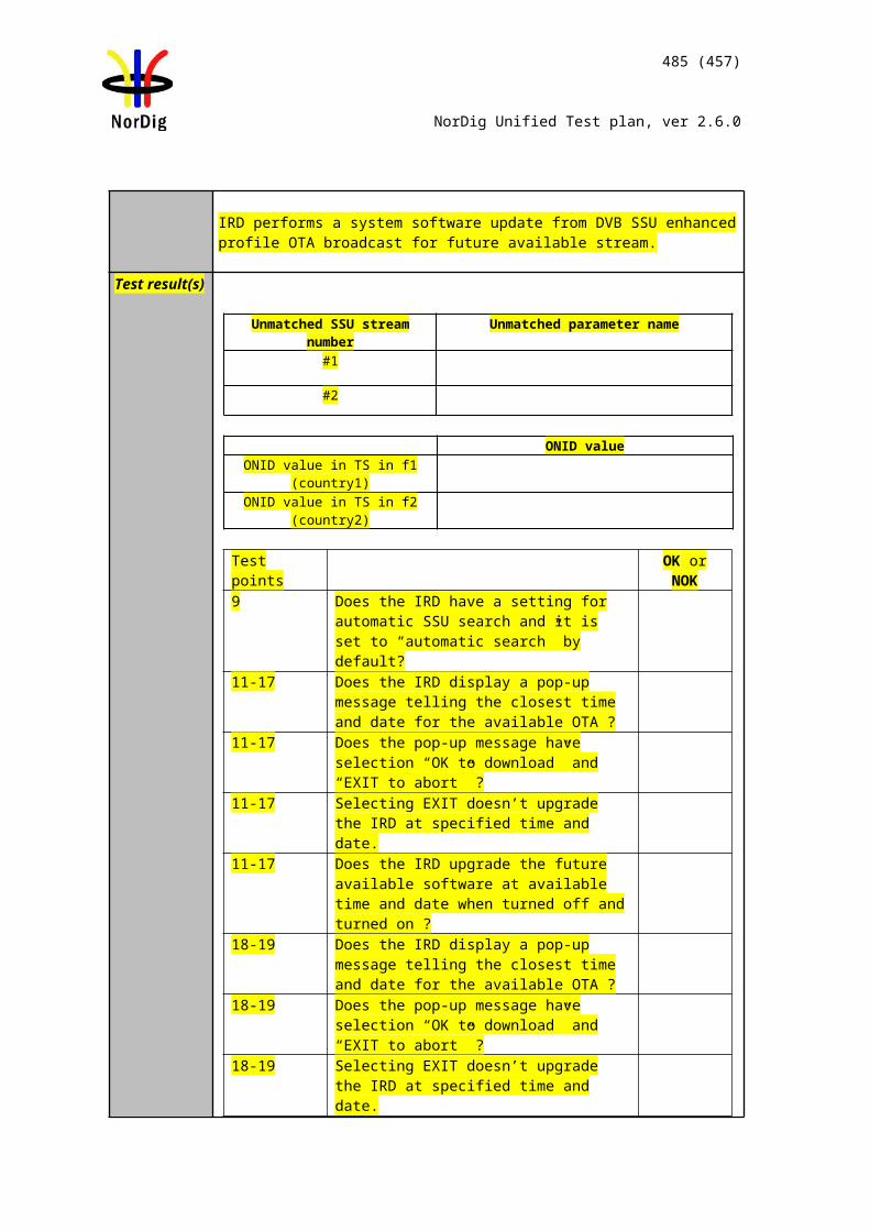
485 (457)
NorDig Unified Test plan, ver 2.6.0
NorDig Test TaskTest TaskTask 16:2 org.nordig_00000020 Current time, no TDT/TOT tables, NTP availableTask 16:3 org.nordig_00000030 Current time, no TDT/TOT tables, no NTP, but SNTP is availableTask 16:4 org.nordig_00000100 parental control, blocking applicationTask 16:5 org.nordig_00000300 EBU teletext, no HbbTV teletextTask 16:6 org.nordig_00000310 HbbTV teletext, no EBU teletextTask 16:7 org.nordig_00000320 EBU teletext and HbbTV teletextTask 16:8 org.nordig_00000330 EBU Teletext, HbbTV teletext signalled but not availableTask 16:9 org.nordig_00000340 No EBU Teletext, no HbbTV teletextTask 16:10 org.nordig_00000350 No EBU teletext, HbbTV teletext signalled but not availableTask 16:11 org.nordig_00000400 EBU subtitles over broadband TS, A/V object, no scalingTask 16:12 org.nordig_00000410 EBU subtitles over broadband TS, A/V object scaled downTask 16:13 org.nordig_00000420 EBU subtitles over broadband TS, A/V object scaled upTask 16:14 org.nordig_00000430 DSM-CC stream events and DVB subtitlesTask 16:15 org.nordig_00000440 DSM-CC stream events and EBU subtitlesTask 16:16 org.nordig_00000500 Broadcast video scaling, 1 x 1Task 16:17 org.nordig_00000510 Broadband TS video scaling, 1 x 1Task 16:18 org.nordig_00000520 Broadband MP4 video scaling, 1 x 1Task 16:19 org.nordig_00000600 EIT P/F, charactersTask 16:20 org.nordig_00000610 EIT MetadataSearch, charactersTask 16:21 org.nordig_00001010 Exit button on broadcast independent application: restore broadcast videoTask 16:22 org.nordig_00001020 Exit button: restore broadcast video from PIP modeTask 16:23 org.nordig_00001050 Setting of preferredUILanguageTask 16:24 org.nordig_00001060 Updating preferredUILanguage after language change in NavigatorTask 16:25 org.nordig_00001070 Switch subtitles: DVB to EBU teletextTask 16:26 org.nordig_00001080 Switch subtitles: EBU teletext to DVBTask 16:27 org.nordig_00001081 Switch subtitles over broadband TS: EBU teletext to DVBTask 16:28 org.nordig_00001082 Switch subtitles over broadband TS: DVB teletext to EBUTask 16:29 org.nordig_00001100 Disabling subtitlesTask 16:30 org.nordig_00001101 Disabling subtitles over broadband TSTask 16:31 org.nordig_00001200 DVB subtitles - V/B Object not bound to current channelTask 16:32 org.nordig_00001210 DVB subtitles - V/B Object bound to current channelTask 16:33 org.nordig_00001220 EBU Teletext subtitles: Video/Broadcast Object not bound to current channelTask 16:34 org.nordig_00001230 EBU Teletext subtitles: Video/Broadcast Object bound to current channelTask 16:35 org.nordig_00001240 DVB subtitles placed behind application, V/B Object not bound to current channelTask 16:36 org.nordig_00001250 DVB subtitles placed behind application, V/B Object bound to current channelTask 16:37 org.nordig_00001260 EBU Teletext subtitles behind application, V/B Object not bound to current channelTask 16:38 org.nordig_00001270 EBU Teletext subtitles behind application, V/B Object bound to current channelTask 16:39 org.nordig_00001280 DVB subtitles, V/B object scaled down (1/4 x 1/4)Task 16:40 org.nordig_00001290 DVB subtitles, V/B object scaled up ( 2 x 2 )Task 16:41 org.nordig_00001300 DVB subtitles behind application, V/B object scaled down ( 1/4 x 1/4 )Task 16:42 org.nordig_00001310 DVB subtitles behind application V/B object scaled up ( 2 x 2 )Task 16:43 org.nordig_00001320 EBU Teletext subtitles, V/B object scaled down (1/4 x 1/4)Task 16:44 org.nordig_00001330 EBU Teletext subtitles, V/B object scaled up ( 2 x 2 )Task 16:45 org.nordig_00001340 EBU Teletext subtitles behind application, V/B object scaled down ( 1/4 x 1/4 )Task 16:46 org.nordig_00001341 EBU Teletext subtitles over broadband TS behind application, A/V object scaled down (1/4x1/4)Task 16:47 org.nordig_00001350 EBU Teletext subtitles behind application, V/B object scaled up ( 2 x 2 )Task 16:48 org.nordig_00001400 DVB subtitles, A/V object - no scalingTask 16:49 org.nordig_00001410 DVB subtitles, A/V object scaled downTask 16:50 org.nordig_00001420 DVB subtitles, A/V object scaled up ( 2 x 2 )Task 16:51 HbbTV global settingTask 16:52 es.tdthibrida_7D7C0040 Broadband DVB subtitles in a TS are displayedTask 16:53 es.tdthibrida_7D7C0050 Broadband Teletext subtitles in a TS are displayedTask 16:54 es.tdthibrida_7D7C0060 Broadband Subtitles Below Application GraphicsTask 16:55 fr.hdforum_00151240 EXIT function is provided by receiverTask 16:56 fr.hdforum_00151250 Termination of autostart application using EXIT functionTask 16:57 fr.hdforum_00151260Termination of non-autostart broadcast-related application using EXIT functionTask 16:58 es.tdthibrida_7D7C0070 Auto-start applications enabled by defaultTask 16:59 fr.hdforum_00151000 Application launching with network connection availableTask 16:60 Teletext - Simultaneous EBU Teletext and HbbTV Digital Teletext (8:6)Task 16:61 Subtitling - coexistent with HbbTV applications (8:7)Task 16:62 Remote Control Key event mapping for NorDig Hybrid (9:11)
2.15.3 Test casesTest Case Task 14:1 – 16:50
Section Multiple (see test case descriptions)Requirement Multiple (see test case descriptions)IRD Profile(s) HybridTest procedure Purpose of test:
See the test case description from the Test Harness / Helper app UI
Equipment:HbbTV Test Harness or NorDig Test Suite helper app
Test procedure:
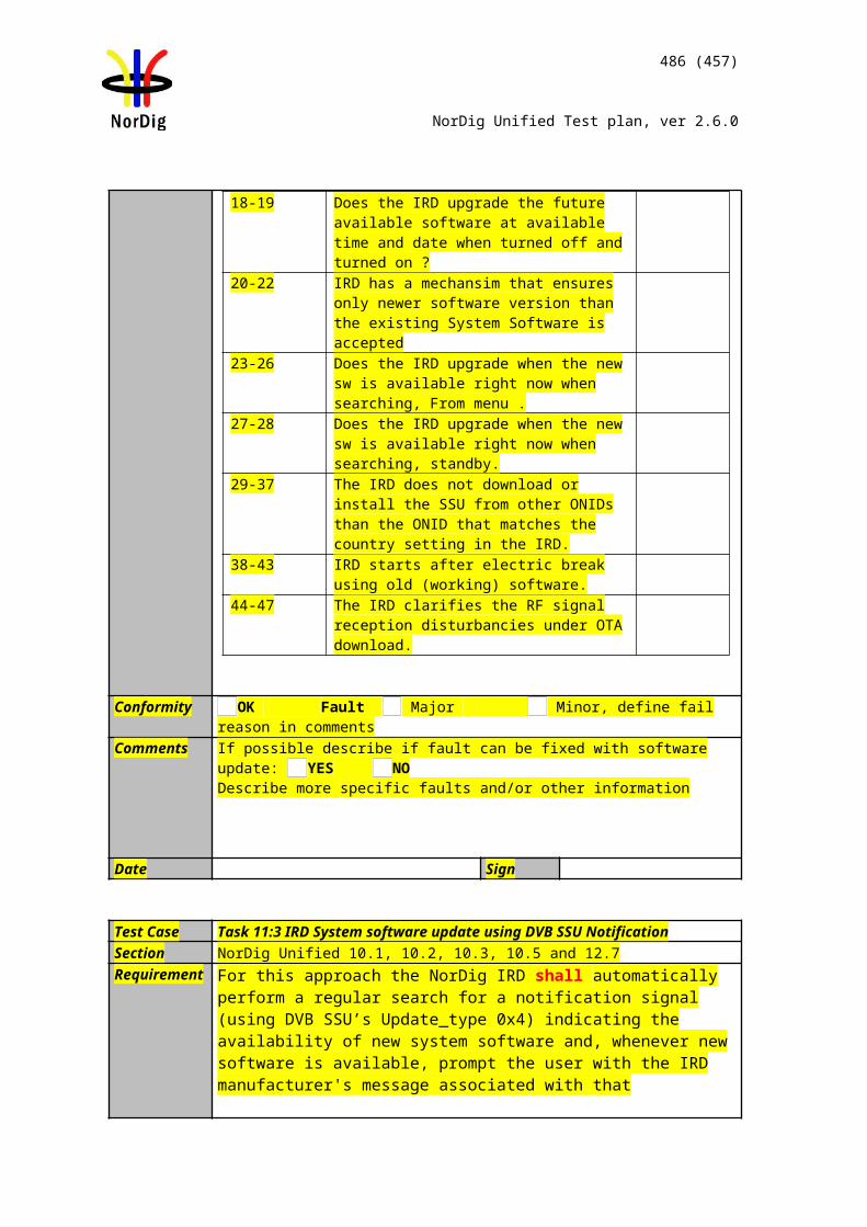
486 (457)
NorDig Unified Test plan, ver 2.6.0
Run the test using the Test Harness or helper app. Follow the on-screen instructions.
Expected result:PASS
Test result(s) Test Harness returns PASS [OK] or FAIL [Fault], mark the result below. Conformity OK [PASS] Fault [NOT OK]Comments If possible describe if fault can be fixed with software update: YES NO
Describe more specific faults and/or other information
Date Sign
Test Case Task 14:51 HbbTV Global setting
Section Nordig Unified 15.2Requirement The NorDig Hybrid HbbTV IRD shall have HbbTV feature as enabled by default (see
Section 16.3). It shall have a menu option to allow user to enable / disable the HbbTV feature as a whole and it should have a menu option to allow user to enable / disable the HbbTV feature service by service.
IRD Profile(s) HybridTest procedure Purpose of test:
Verify that the IRD has an option to turn HbbTV on and off globally.
Equipment:IRD under test.Stream with a HbbTV application signalled.
Test procedure:1. Turn HbbTV setting OFF2. Check that HbbTV application is not launched.3. Turn HbbTV setting ON4. Check that HbbTV application is launched.
Expected result:PASS
Test result(s) [OK] or FAIL [Fault], mark the result below. Conformity OK Fault Major Minor, define fail reason in commentsComments If possible describe if fault can be fixed with software update: YES NO
Describe more specific faults and/or other information
Date Sign
Test Case Task 14:52 – 16:59 (es.TDThibrida and fr.HDForum tests)
Section Multiple (see test case descriptions)Requirement Multiple (see test case descriptions)IRD Profile(s) HybridTest procedure Purpose of test:
See the test case description from the Test Harness.
Equipment:HbbTV Test Harness.
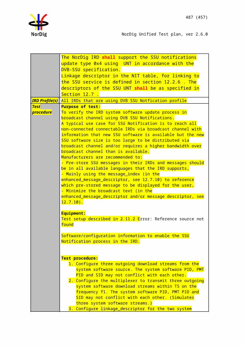
487 (457)
NorDig Unified Test plan, ver 2.6.0
Test procedure:Run the test using the Test Harness. Follow the on-screen instructions.
Expected result:PASS
Test result(s) Test Harness returns PASS [OK] or FAIL [Fault], mark the result below. Conformity OK [PASS] Fault [NOT OK]Comments If possible describe if fault can be fixed with software update: YES NO
Describe more specific faults and/or other information
Date Sign
Test Case Task 14:60 Teletext - Simultaneous EBU Teletext and HbbTV Digital Teletext (8:6)
Section NorDig Unified 7.1.6Requirement For services that have both an EBU Teletext service and an HbbTV Digital Teletext
application signaled and available, the NorDig Hybrid HbbTV shall (1) be able to start anddisplay the HbbTV Digital Teletext application as well as being able to start and displaythe EBU Teletext service (one at a time).The NorDig Hybrid shall (1) start teletext and be able to toggle between any HbbTVDigital Teletext and any EBU Teletext service as described in clause 5.3.4 of HbbTV specification ETSI TS 102 796.
IRD Profile(s) HybridTest procedure Purpose of test:
To verify that the IRD is able to start EBU Teletext and HbbTV Digital Teletext (one atthe time).A transport stream containing a test services with EBU Teletext and HbbTV DigitalTelext application is required.
Test procedure:1. Tune to a serve that contains both EBU Teletext and HbbTV Digital Teletextapplication.2. Verify that the user can toggle between EBU Teletext and HbbTV DigitalTeletext application by pressing the “text” button in the RCU.
Expected result:User can toggle between EBU Teletext and HbbTV Digital Teletext application.
Test result(s) [OK] or FAIL [Fault], mark the result below. Conformity OK Fault Major Minor, define fail reason in commentsComments If possible describe if fault can be fixed with software update: YES NO
Describe more specific faults and/or other information
Date Sign
Test Case Task 14:61 Subtitling - coexistent with HbbTV applications (8:7)
Section NorDig Unified 7.1.7Requirement A NorDig Hybrid shall support simultaneous display of HbbTV application and
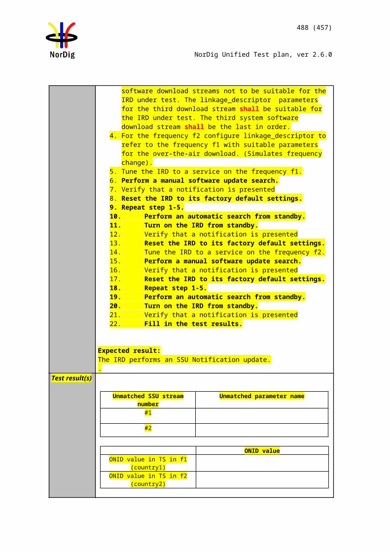
488 (457)
NorDig Unified Test plan, ver 2.6.0
subtitles (DVB subtitling and EBU teletext subtitling), both for broadcast and at leastfor MPEG2 TS delivered via broadband [29].
The NorDig Hybrid HbbTV shall display the HbbTV application over the subtitles as describedin clause 10.1.1 of HbbTV specification ETSI TS 102 796 [30]. This means that if thevideo is up or down-converted, to other than full screen video, the subtitles shall eitherbe rescaled/repositioned appropriately or not displayed at all.
IRD Profile(s) HybridTest procedure Purpose of test:
To verify that DVB and EBU teletext subtitling can coexists with HbbTV applications.
A transport stream containing a test service with DVB and EBU teletext composition subtitling component and at least one signaled service bound HbbTV application at thesame channel.
Test procedure:1. set the IRD to the autostart mode for the HbbTV services and eansure thatsubtitles are enabled2. search channels3. zap to a channel that contains the HbbTV service and subtitles4. verify that when the HbbTV application is not using the same graphics plane orarea of the plane as the subtitles, the subtitles are visible
Expected result:The subtitles are visible with a HbbTV application, when they are not sharing the samearea of the graphics plane.
Test result(s) [OK] or FAIL [Fault], mark the result below. Conformity OK Fault Major Minor, define fail reason in commentsComments If possible describe if fault can be fixed with software update: YES NO
Describe more specific faults and/or other information
Date Sign
Test Case Task 14:62 Remote Control Key event mapping for NorDig Hybrid (9:11)
Section NorDig 8.7.2.6Requirement The NorDig Hybrid HbbTV IRD shall generate (HbbTV) events according to Table 8.3
when akey is pressed on the NorDig IRD remote control.
IRD Profile(s) HybridTest procedure Test procedure:
Check the manufacturer technical specification / compliance list or verify the remotecontrol functions.
Expected result:The minimum hardware requirement is fulfilled.
Test result(s) [OK] or FAIL [Fault], mark the result below. Conformity OK Fault Major Minor, define fail reason in commentsComments If possible describe if fault can be fixed with software update: YES NO
Describe more specific faults and/or other information
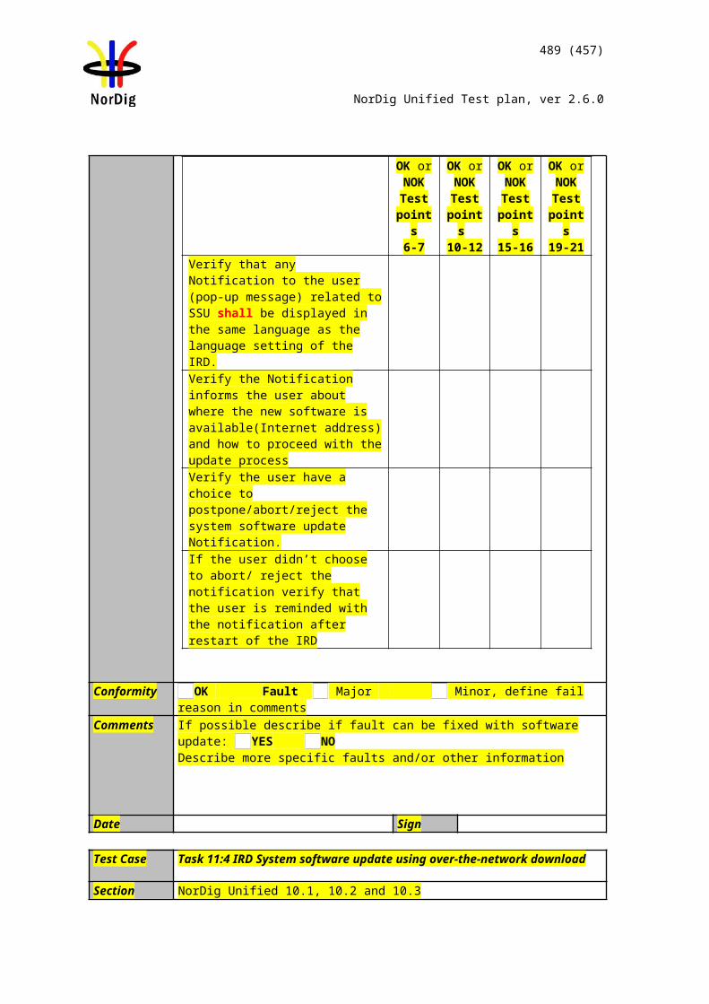
489 (457)
NorDig Unified Test plan, ver 2.6.0
Date Sign
490 (457)
NorDig Unified Test plan, ver 2.6.0
2.16 Task 17: User PreferencesTest Case Task 15:1 Stored preferences
Section NorDig Unified 16.1 and 16.2Requirement The user shall be able to store preference settings in persistent memory. All user
preference settings listed below shall remain when changing service and when re-starting the IRD. The following user preferences shall be implemented in the NorDig IRD, unless it is stated below as optional (should) requirement. (See section 16.4 for factory default values).
IRD Profile(s) Basic, IRD, FETest procedure Purpose of test:
To verify stored user preferences
Equipment:
Test procedure:1. Verify following user preferences:
* Service list* Coutry settings* Talking menus/Text-to-speech* SSU settings* HbbTV settings* HDCP preferences (Optional)
* Video display preferences* Audio preferences* Primary and secondary audio language preferences* Primary and secondary subtitling language preferences* Service list preferences* Country settingspreferences* Audio transcoding preferences* HDMI preferences* Supplementary Audio settings
Expected result: User preferences are as defined.
Test result(s)Conformity OK Fault Major Minor, define fail reason in commentsComments If possible describe if fault can be fixed with software update: YES NO
Describe more specific faults and/or other information
Date Sign
491 (457)
NorDig Unified Test plan, ver 2.6.0
Test Case Task 15:2 Deletion of service lists
Section NorDig Unified 16.3Requirement The IRD shall provide a function to remove all service lists (default and user defined) and
should not affecting other parameters (e.g. user preferences).
IRD Profile(s) Basic, IRD, FETest procedure Purpose of test:
To verify deletion of the service lists
Equipment:
Test procedure:
1. Verify if the receiver supports a mechanism to only remove service lists. 2. Verify that the service list(s) exists3. Remove service list(s)4. Verify remove of the service list(s)
Expected result: Service lists are removed.
Test result(s)Conformity OK Fault Major Minor, define fail reason in commentsComments If possible describe if fault can be fixed with software update: YES NO
Describe more specific faults and/or other information
Date Sign
Test Case Task 15:3 Reset to factory mode
Section NorDig Unified 16.4Requirement The IRD shall provide a function to reset all parameters to factory mode, thus removing
all service lists, user preferences, etc. After reset, the IRD shall enter installation state.
IRD Profile(s) Basic, IRD, FETest procedure Purpose of test:
To verify the reset function.
Equipment:
Test procedure:1. Locate the reset to factory mode function in the IRD and initiate it.2. Check that the service list and user preferences have been deleted.3. Enter the navigator and check that the factory mode meets the requirements.
492 (457)
NorDig Unified Test plan, ver 2.6.0
4. Fill in the test protocol.
Expected result: The IRD has the user preference settings according the requirements.
Test result(s) Test protocol
Requirement Value NOK or OK
RF input DC power supply source for satellite front-end:
on
RF input DC power supply source for terrestrial front-end:
off (1)
RF-output preset channel: Channel 43 (PAL-G) (2)
RF bypass gain DisabledMenu language: equal to country
settings Audio (normal) OnPrimary audio language: equal to country
settings Audio format setting: StereoAudio; hard of hearing/hearing im-paired:
Off
Subtitling (normal): on Primary subtitling language: as country settings Subtitling; hard of hearing/hearing im-paired:
off
HbbTV Interactivity OnHDMI Audio output Automatic using
EDID informationHDMI Video output Automatic using
EDID informationHDCP ON or as specified
by the relevant net-work/ CA operator see section 9.11.4 (1)
SSU – mode Semi-automatic (if supported, otherwise a mode that enables automatic search)
PVR recording priority, SD vs HD HDTalking menus (Text-to-Speech), op-tional
Off
Conformity OK Fault Major Minor, define fail reason in commentsComments If possible describe if fault can be fixed with software update: YES NO
Describe more specific faults and/or other information
493 (457)
NorDig Unified Test plan, ver 2.6.0
Date Sign
494 (457)
NorDig Unified Test plan, ver 2.6.0
AnnexA: NorDig Network CustodiansThe NorDig Network Custodians are represented (per June 17th, 2008) by the following companies in the Nordic countries and relevant networks:
Country/Network Contact informationDenmark
Cable Networks To be definedSatellite Networks To be definedTerrestrial Network To be definedFinland
Cable Networks Labwise Oy (test laboratory)Tel. +358 3 214 0010Email: [email protected]: www.kaapelitelevisio.fi or www.labwise.fi
Satellite Networks To be definedTerrestrial Networks Labwise Oy (test laboratory)
Tel. +358 3 214 0010Email: [email protected]: www.labwise.fi
Iceland
Cable Networks To be definedSatellite Networks To be definedTerrestrial Networks To be definedNorway
Cable Networks To be definedSatellite Networks Telenor Broadcast Holding AS / Canal Digital Technology & IS
Tel.Email:Web:
Terrestrial Networks To be definedSweden
Cable Networks To be definedSatellite Networks Tob e definedTerrestrial Networks Receivers for pay TV services:
Boxer TV Access AB (operator)Tel: +46 8 587 899 00 (switchboard)Email: [email protected]: www.boxer.se
Any other type of receivers; e.g. professional, OEM, free-to-view, reference designs:TeracomAB (network operator)Tel: +46 8 555 420 00 (switchboard)Email: [email protected]: www.teracom.se
495 (457)
NorDig Unified Test plan, ver 2.6.0