Embed Size (px)
Citation preview
Introduction 1Purpose 1Conditions of using the template 1Updating and developing this DEEP 2
Digital engineering execution plan 3Basis of document 3Requirement terminology 3Section 1: Project information 4Section 2: Governance 8Section 3: Management 15Section 4: Technical 31
Introduction
PurposeThis document provides the delivery team with the minimum inclusions and a standard format for a project-specific digital engineering execution plan (DEEP).
It will help facilitate communication of digital asset information between the following stakeholders:
● asset owners, including Victorian Government departments, agencies, or those representing their best interests;
● facilities management professionals, including operators;
● asset management professionals, including those responsible for asset-level decisions; and
● project delivery professionals, such as engineers, constructors, commissioners.
This document is tailored to ensure the lead Appointed Party to respond to the exchange information requirements (EIR). Depending on the contract type and what VDAS stages the contract extends across, this template will need to change.
For example, if there is a design-only EIR (i.e. no construction within the contract), then various parts will need to be modified.
Equally, prior to Construction, the DEEP should be updated to reflect the approach for construction, commissioning and handover. This document should meet the EIR, organisation information requirements (OIR) and asset information requirements (AIR), as defined by the Appointing Party.
Consultants and contractors are to respond to this EIR with a DEEP. The EIR used to create this DEEP is featured in Appendix 5.
This document does not provide guidance on digital engineering or the Victorian Digital Asset Strategy (VDAS) process. This can be found on the OPV website (www.opv.vic.gov.au)
Conditions of using the templateEvery project, asset, department and organisation is different and every project responds to unique organisational needs. There is no single template that will be equally applicable in all these circumstances.
It is the responsibility of the document author, typically the DE Lead from the Lead Appointed Party, to interpret and validate what the project, asset, department and organisation is seeking to achieve, and compose a document that responds to that need accordingly. This template is a tool that can assist with that process.
The document should be read in conjunction with other VDAS documents addressing the digital engineering process.
How to use this template:This template has instructional text directed at the Appointing Party. It is the obligation of the Appointing Party to fill this out and apply it in the context of the project, the AIR and the OIR.
Victorian Digital Asset Strategy Guidance: Appendix 6 Page 1
Updating and developing this DEEPA strategy for how this DEEP will be updated and developed during the lifecycle of the project.
This digital engineering execution plan (DEEP) has been developed to facilitate the delivery of the [insert project name] project. It is a live document, and will be appropriately updated throughout the course of the project to ensure it reflects EIR’s information and delivery requirements. This includes the current project phase and scope, project team structure and capabilities.This DEEP is to be actively managed and updated throughout the course of the project to ensure that it remains relevant to the project scope, digital engineering strategy, contract structure and available resources (tools/IT systems and personnel).This DEEP must include any changes requested by the Appointing Party, as deemed necessary to the project.
Victorian Digital Asset Strategy Guidance: Appendix 6 Page 2
Digital engineering execution plan
Basis of documentThis section outlines the structure of the DEEP for the lead Appointed Party. It will need to be modified for each organisation, project and situation.This DEEP is divided into four sections:
● Section 1: Project information – sets out the basic project information, the structure of the DEEP and provides relevant glossary and acronyms;
● Section 2: Governance – provides an overview of key owner-side contacts (Appointing Party) for the project;
● Section 3: Management – provides clarification on standards, soft landings, data drops, QA/QC, federation, communication and roles and responsibilities;
● Section 4: Technical requirements – describes the scope and specification of the Services; and
● Section 5: Project phases – describes the execution plan in each project phase.
Requirement terminologyThis section articulates the ‘language’ of compliance. The following terms have defined meanings. Care must be taken to ensure their appropriate use throughout this document. These must be aligned with the norms associated with contracts in the department/agency. must – describes mandatory requirements; should – describes non-mandatory, best practice
recommendations; and may – describes possible options that are neither
mandatory nor best practice.It may be worth articulating within this section how the Appointed Parties can demonstrate compliance. Users of this requirement must explicitly demonstrate compliance through: adopting appropriate standards and providing
explicit reasons for their selection; or providing an explicit, evidence based, business
case supporting compliance with this standard.Further, it may be worthwhile articulating the process around deviation from requirements -- how, when, who, why?Where the deliverables of this requirement are not able to be met through the design process, a request for deviation must be made. Requests for deviation must explicitly state the areas where a proposal does not comply. As a minimum, submissions must include detailed commentary on: the reason for deviation from this standard; how the deviation complies with all other
mandatory standards or regulations; and any impacts on safety, reliability, ongoing cost,
operability and maintenance.
Victorian Digital Asset Strategy Guidance: Appendix 6 Page 3
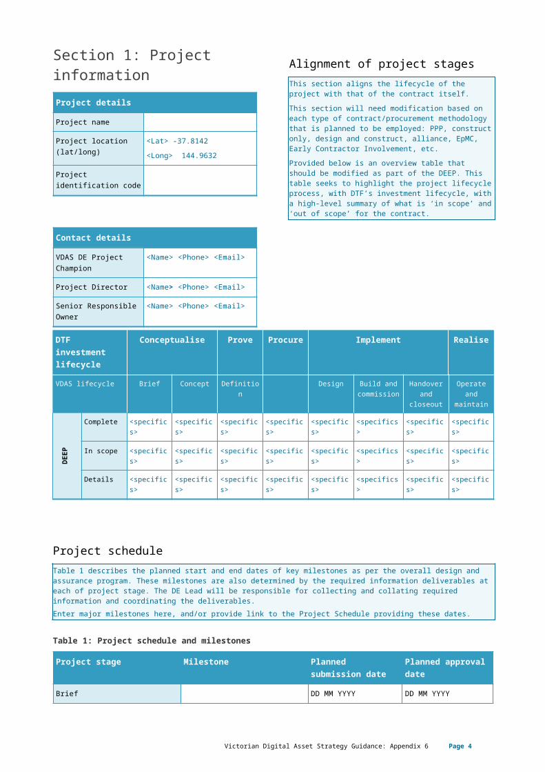
Section 1: Project informationProject details
Project name
Project location(lat/long)
<Lat> -37.8142<Long> 144.9632
Project identification code
Contact details
VDAS DE Project Champion
<Name> <Phone> <Email>
Project Director <Name> <Phone> <Email>
Senior Responsible Owner
<Name> <Phone> <Email>
Alignment of project stagesThis section aligns the lifecycle of the project with that of the contract itself. This section will need modification based on each type of contract/procurement methodology that is planned to be employed: PPP, construct only, design and construct, alliance, EpMC, Early Contractor Involvement, etc.Provided below is an overview table that should be modified as part of the DEEP. This table seeks to highlight the project lifecycle process, with DTF’s investment lifecycle, with a high-level summary of what is ‘in scope’ and ‘out of scope’ for the contract.
DTF investment lifecycle
Conceptualise Prove Procure Implement Realise
VDAS lifecycle Brief Concept Definition Design Build and commission
Handover and
closeout
Operate and
maintain
DEE
P
Complete <specifics>
<specifics>
<specifics>
<specifics>
<specifics>
<specifics> <specifics>
<specifics>
In scope <specifics>
<specifics>
<specifics>
<specifics>
<specifics>
<specifics> <specifics>
<specifics>
Details <specifics>
<specifics>
<specifics>
<specifics>
<specifics>
<specifics> <specifics>
<specifics>
Project scheduleTable 1 describes the planned start and end dates of key milestones as per the overall design and assurance program. These milestones are also determined by the required information deliverables at each of project stage. The DE Lead will be responsible for collecting and collating required information and coordinating the deliverables.Enter major milestones here, and/or provide link to the Project Schedule providing these dates.
Table 1: Project schedule and milestones
Project stage Milestone Planned submission date
Planned approval date
Brief DD MM YYYY DD MM YYYY
Concept DD MM YYYY DD MM YYYY
DD MM YYYY DD MM YYYY
Definition DD MM YYYY DD MM YYYY
Victorian Digital Asset Strategy Guidance: Appendix 6 Page 4
DD MM YYYY DD MM YYYY
DD MM YYYY DD MM YYYY
DD MM YYYY DD MM YYYY
DD MM YYYY DD MM YYYY
Design DD MM YYYY DD MM YYYY
DD MM YYYY DD MM YYYY
Building and commission DD MM YYYY DD MM YYYY
DD MM YYYY DD MM YYYY
Handover and closeout DD MM YYYY DD MM YYYY
Operation and maintenance DD MM YYYY DD MM YYYY
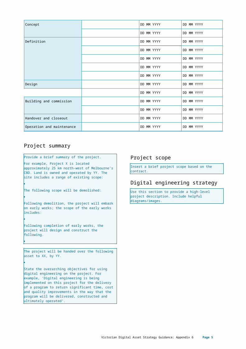
Project summaryProvide a brief summary of the project.For example, Project X is located approximately 25 km north-west of Melbourne’s CBD. Land is owned and operated by YY. The site includes a range of existing scope:
The following scope will be demolished:
Following demolition, the project will embark on early works; the scope of the early works includes:
Following completion of early works, the project will design and construct the following.
The project will be handed over the following asset to XX, by YY.
State the overarching objectives for using digital engineering on the project. For example, ‘Digital engineering is being implemented on this project for the delivery of a program to return significant time, cost and quality improvements in the way that the program will be delivered, constructed and ultimately operated’.
Project scopeInsert a brief project scope based on the contract.
Digital engineering strategy Use this section to provide a high-level project description. Include helpful diagrams/images.
Digital engineering objectives/usesFor example, the Appointing Party is focused on the following benefits and outcomes when digital engineering is used during design, construction, commissioning and operations. These objectives form the definition uses of digital engineering and constitute the requirements to be addressed by the project delivery team.The Appointing Party is staging the implementation of digital engineering in line with industry readiness over a phased time horizon. In Table 3, confirm the delivery team processed digital engineering uses for the project.(Note: where a digital engineering use applies, copy and paste the tick symbol in the appropriate cell. If a use is not applicable, please leave the cell blank).
Victorian Digital Asset Strategy Guidance: Appendix 6 Page 5
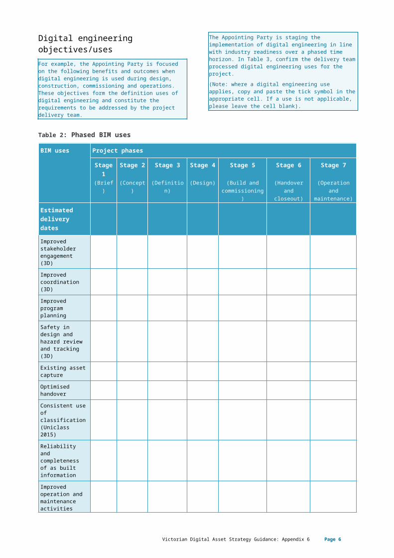
Table 2: Phased BIM uses
BIM uses Project phases
Stage 1
Stage 2 Stage 3 Stage 4 Stage 5 Stage 6 Stage 7
(Brief) (Concept) (Definition) (Design) (Build and commissioning)
(Handover and closeout)
(Operation and maintenance)
Estimated delivery dates
Improved stakeholder engagement (3D)Improved coordination (3D)Improved program planning Safety in design and hazard review and tracking (3D)Existing asset capture Optimised handover Consistent use of classification (Uniclass 2015)Reliability and completeness of as built informationImproved operation and maintenance activitiesImproved cost management Progress claims associated to the model (5D)Improved management of asset information using interconnected data (6D)
Digital set out to complement traditional surveying techniques
Other
Innovation and value adding opportunitiesEach project should demonstrate innovation or
Victorian Digital Asset Strategy Guidance: Appendix 6 Page 6
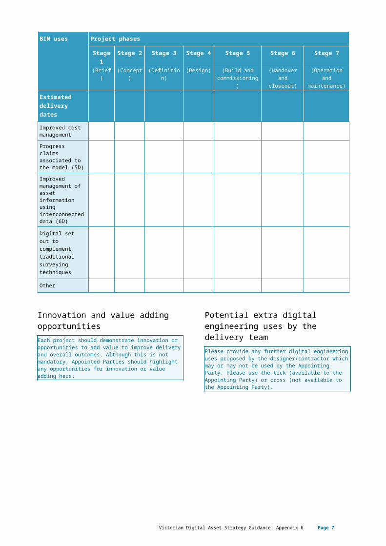
opportunities to add value to improve delivery and overall outcomes. Although this is not mandatory, Appointed Parties should highlight any opportunities for innovation or value adding here.
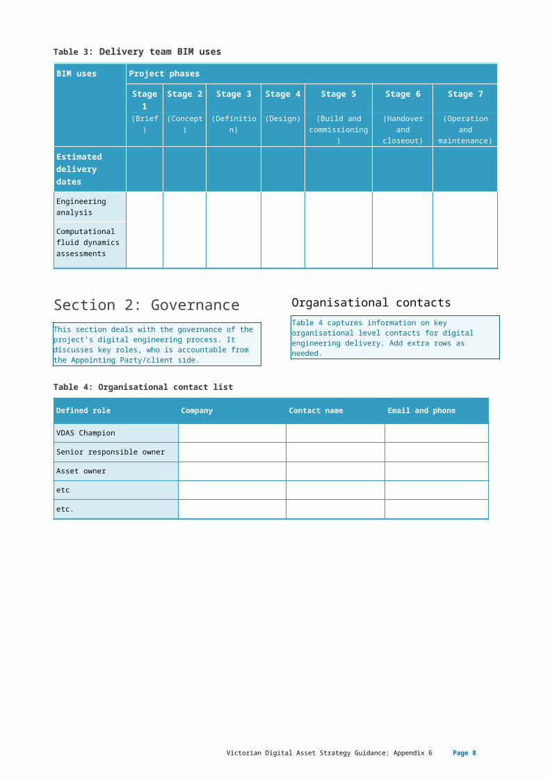
Potential extra digital engineering uses by the delivery teamPlease provide any further digital engineering uses proposed by the designer/contractor which may or may not be used by the Appointing Party. Please use the tick (available to the Appointing Party) or cross (not available to the Appointing Party).
Table 3: Delivery team BIM uses
BIM uses Project phases
Stage 1
Stage 2 Stage 3 Stage 4 Stage 5 Stage 6 Stage 7
(Brief) (Concept) (Definition) (Design) (Build and commissioning)
(Handover and closeout)
(Operation and maintenance)
Estimated delivery dates
Engineering analysis
Computational fluid dynamics assessments
Section 2: GovernanceThis section deals with the governance of the project’s digital engineering process. It discusses key roles, who is accountable from the Appointing Party/client side.
Organisational contactsTable 4 captures information on key organisational level contacts for digital engineering delivery. Add extra rows as needed.
Table 4: Organisational contact list
Defined role Company Contact name Email and phone
VDAS Champion
Senior responsible owner
Asset owner
etc
etc.
Victorian Digital Asset Strategy Guidance: Appendix 6 Page 7
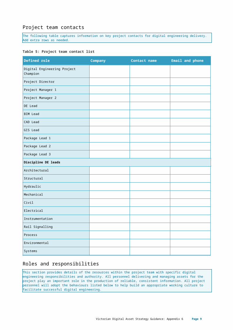
Project team contactsThe following table captures information on key project contacts for digital engineering delivery. Add extra rows as needed.
Table 5: Project team contact list
Defined role Company Contact name Email and phone
Digital Engineering Project Champion
Project Director
Project Manager 1
Project Manager 2
DE Lead
BIM Lead
CAD Lead
GIS Lead
Package Lead 1
Package Lead 2
Package Lead 3
Discipline DE leads
Architectural
Structural
Hydraulic
Mechanical
Civil
Electrical
Instrumentation
Rail Signalling
Process
Environmental
Systems
Roles and responsibilitiesThis section provides details of the resources within the project team with specific digital engineering responsibilities and authority. All personnel delivering and managing assets for the project play an important role in the production of reliable, consistent information. All project personnel will adopt the behaviours listed below to help build an appropriate working culture to facilitate successful digital engineering.
Table 6: Project team behaviours
Ref Activities Description
1 Share, collaborate, deliver All personnel have a responsibility to share information, and where required, coordinate and collaborate to deliver EIR required digital engineering outcomes.
Victorian Digital Asset Strategy Guidance: Appendix 6 Page 8
2 Use common language Use a common language so people can effectively exchange information.
3 Demonstrate an auditable assurance pathway
Resolve issues collaboratively, manage risks and track decisions to provide a traceable and auditable pathway through design development up until asset disposal.
4 Provide and use digital tools to support decision making
Implement effective tools and provide training so personnel are empowered to make decisions using the best available information.
5 Support and strive to adopt best practice
Use digital engineering tools and processes to drive innovation in the way projects are delivered.
All nominated roles will have completed the appropriate and relevant training prior to project commencement. These roles may be performed by the same person depending on the size of the project. Any equivalent roles to the below nominated roles in Table 7 can be proposed.
Victorian Digital Asset Strategy Guidance: Appendix 6 Page 9
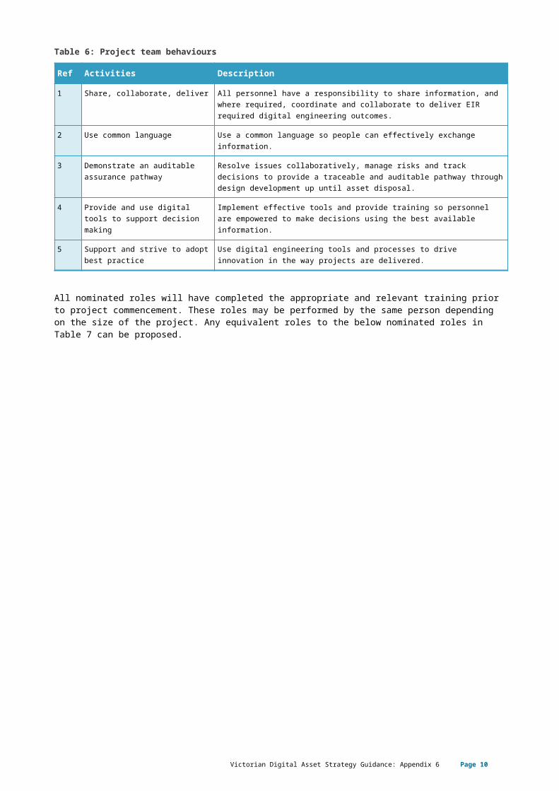
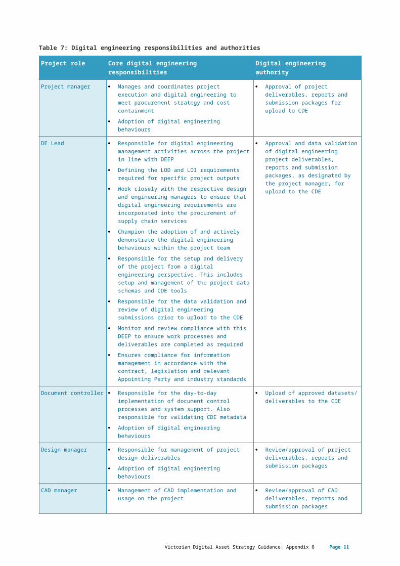
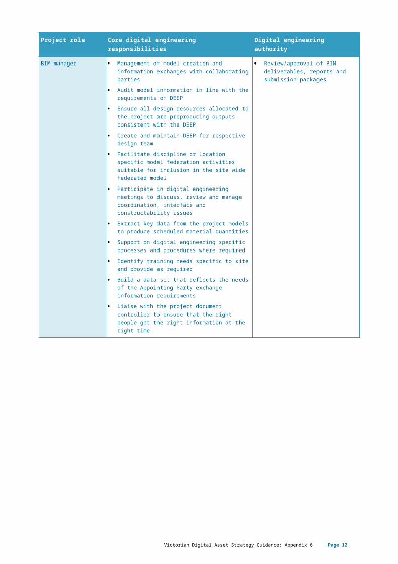
Table 7: Digital engineering responsibilities and authorities
Project role Core digital engineering responsibilities Digital engineering authority
Project manager Manages and coordinates project execution and digital engineering to meet procurement strategy and cost containment
Adoption of digital engineering behaviours
Approval of project deliverables, reports and submission packages for upload to CDE
DE Lead Responsible for digital engineering management activities across the project in line with DEEP
Defining the LOD and LOI requirements required for specific project outputs
Work closely with the respective design and engineering managers to ensure that digital engineering requirements are incorporated into the procurement of supply chain services
Champion the adoption of and actively demonstrate the digital engineering behaviours within the project team
Responsible for the setup and delivery of the project from a digital engineering perspective. This includes setup and management of the project data schemas and CDE tools
Responsible for the data validation and review of digital engineering submissions prior to upload to the CDE
Monitor and review compliance with this DEEP to ensure work processes and deliverables are completed as required
Ensures compliance for information management in accordance with the contract, legislation and relevant Appointing Party and industry standards
Approval and data validation of digital engineering project deliverables, reports and submission packages, as designated by the project manager, for upload to the CDE
Document controller Responsible for the day-to-day implementation of document control processes and system support. Also responsible for validating CDE metadata
Adoption of digital engineering behaviours
Upload of approved datasets/ deliverables to the CDE
Design manager Responsible for management of project design deliverables
Adoption of digital engineering behaviours
Review/approval of project deliverables, reports and submission packages
CAD manager Management of CAD implementation and usage on the project
Review/approval of CAD deliverables, reports and submission packages
BIM manager Management of model creation and information exchanges with collaborating parties
Audit model information in line with the requirements of DEEP
Ensure all design resources allocated to the project are preproducing outputs consistent with the DEEP
Create and maintain DEEP for respective design team
Facilitate discipline or location specific model federation activities suitable for inclusion in the site wide federated model
Participate in digital engineering meetings to discuss, review and manage coordination,
Review/approval of BIM deliverables, reports and submission packages
Victorian Digital Asset Strategy Guidance: Appendix 6 Page 10
Project role Core digital engineering responsibilities Digital engineering authority
interface and constructability issues Extract key data from the project models to
produce scheduled material quantities Support on digital engineering specific
processes and procedures where required Identify training needs specific to site and
provide as required Build a data set that reflects the needs of the
Appointing Party exchange information requirements
Liaise with the project document controller to ensure that the right people get the right information at the right time
BIM coordinator Responsible for BIM coordinator activities including the audit, review and coordination of model information for project specific precincts and or disciplines as defined within the DEEP
Implement the project specific standards set by the BIM Manager and work with the BIM Manager to define the DEEP including any applicable protocols/manuals
Carry out model validation checks, coordination reviews and liaise with subconsultants or trades
Support the deployment of field data management system, review validity of information collected against information deliverables
Ensure that data exchange protocols are adhered to by the project team and liaise with design team manager on compliance issues
Identify and keep record of BIM specific lessons learnt throughout the project to ensure future projects do not duplicate issues
Review/approval of BIM deliverables and reports
GIS manager Manage GIS implementation and usage on the project
Review/approval of GIS in accordance with project requirements
Scheduler Manage scheduling (4D) implementation and usage on the project
Review/approval of 4D in accordance with project requirements
Cost estimator Manage costing (5D) implementation and usage on the project
Adoption of digital engineering behaviours
Review/approval of 5D in accordance with project requirements
Project task team member
Adoption of digital engineering behaviours Review/approval of technical deliverables as appropriate.
Victorian Digital Asset Strategy Guidance: Appendix 6 Page 11
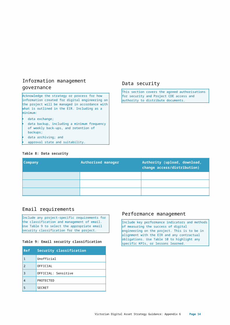
Information management governanceAcknowledge the strategy or process for how information created for digital engineering on the project will be managed in accordance with what is outlined in the EIR. Including as a minimum: data exchange; data backup, including a minimum frequency of
weekly back-ups, and retention of backups; data archiving; and approval state and suitability.
Data securityThis section covers the agreed authorisations for security and Project CDE access and authority to distribute documents.
Table 8: Data security
Company Authorised manager Authority (upload, download, change access/distribution)
Email requirementsInclude any project-specific requirements for the classification and management of email. Use Table 9 to select the appropriate email security classification for the project.
Table 9: Email security classification
Ref Security classification
1 Unofficial
2 OFFICIAL
3 OFFICIAL: Sensitive
4 PROTECTED
5 SECRET
Performance managementInclude key performance indicators and methods of measuring the success of digital engineering on the project. This is to be in alignment with the EIR and any contractual obligations. Use Table 10 to highlight any specific KPIs, or lessons learned.
Victorian Digital Asset Strategy Guidance: Appendix 6 Page 12
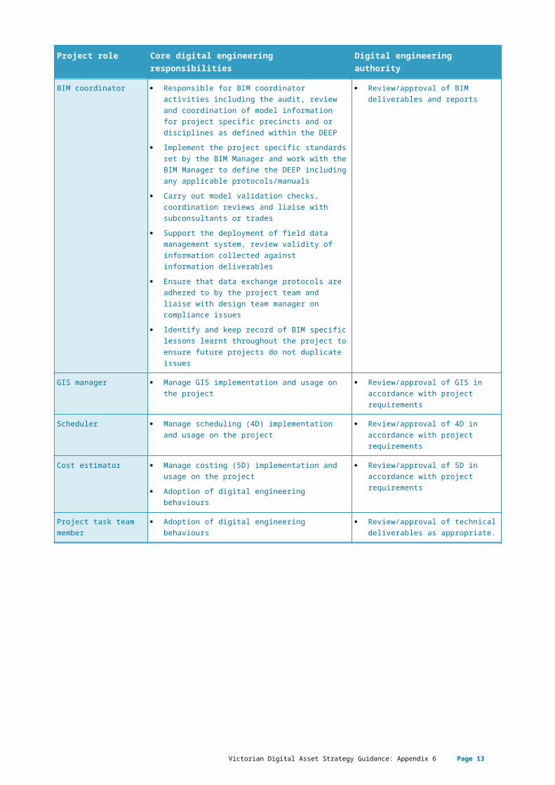
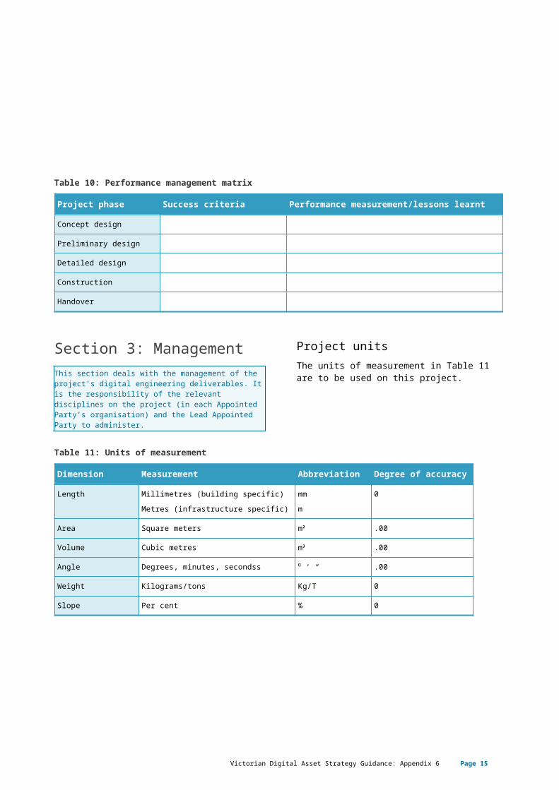
Table 10: Performance management matrix
Project phase Success criteria Performance measurement/lessons learnt
Concept design
Preliminary design
Detailed design
Construction
Handover
Section 3: ManagementThis section deals with the management of the project’s digital engineering deliverables. It is the responsibility of the relevant disciplines on the project (in each Appointed Party’s organisation) and the Lead Appointed Party to administer.
Project unitsThe units of measurement in Table 11 are to be used on this project.
Table 11: Units of measurement
Dimension Measurement Abbreviation Degree of accuracy
Length Millimetres (building specific)Metres (infrastructure specific)
mmm
0
Area Square meters m² .00
Volume Cubic metres m³ .00
Angle Degrees, minutes, secondss ⁰ ‘ “ .00
Weight Kilograms/tons Kg/T 0
Slope Per cent % 0
Victorian Digital Asset Strategy Guidance: Appendix 6 Page 13
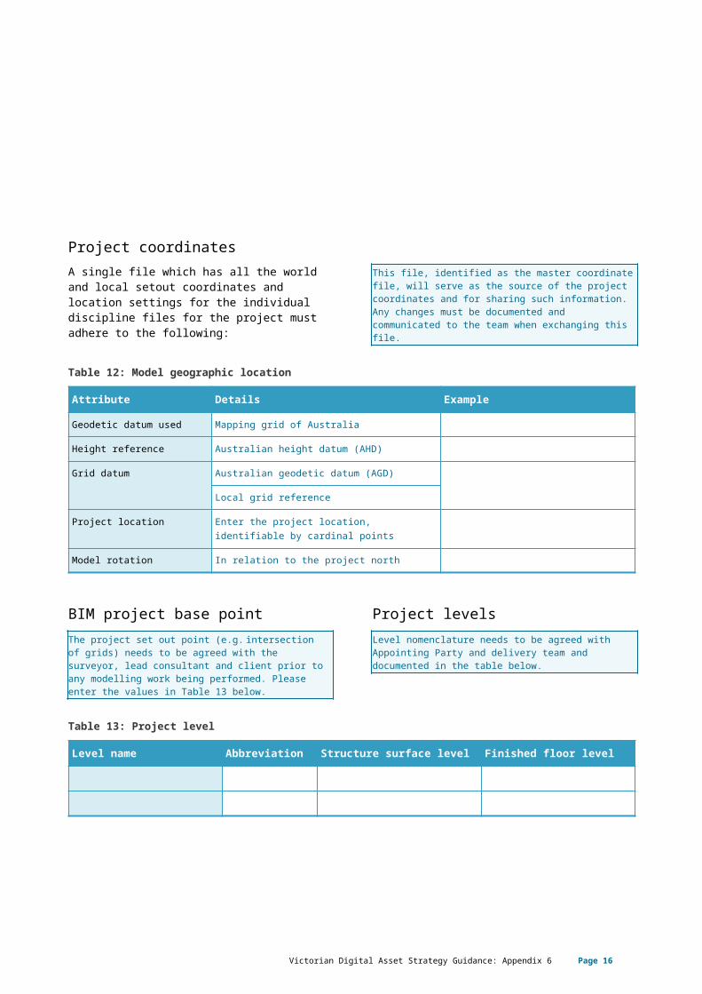
Project coordinatesA single file which has all the world and local setout coordinates and location settings for the individual discipline files for the project must adhere to the following:
This file, identified as the master coordinate file, will serve as the source of the project coordinates and for sharing such information. Any changes must be documented and communicated to the team when exchanging this file.
Table 12: Model geographic location
Attribute Details Example
Geodetic datum used Mapping grid of Australia
Height reference Australian height datum (AHD)
Grid datum Australian geodetic datum (AGD)
Local grid reference
Project location Enter the project location, identifiable by cardinal points
Model rotation In relation to the project north
BIM project base pointThe project set out point (e.g. intersection of grids) needs to be agreed with the surveyor, lead consultant and client prior to any modelling work being performed. Please enter the values in Table 13 below.
Project levelsLevel nomenclature needs to be agreed with Appointing Party and delivery team and documented in the table below.
Table 13: Project level
Level name Abbreviation Structure surface level Finished floor level
Victorian Digital Asset Strategy Guidance: Appendix 6 Page 14
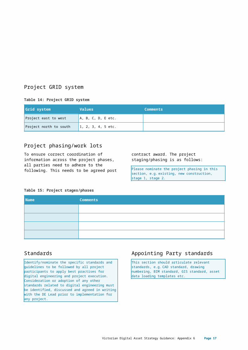
Project GRID system
Table 14: Project GRID system
Grid system Values Comments
Project east to west A, B, C, D, E etc.
Project north to south 1, 2, 3, 4, 5 etc.
Project phasing/work lotsTo ensure correct coordination of information across the project phases, all parties need to adhere to the following. This needs to be
agreed post contract award. The project staging/phasing is as follows:
Please nominate the project phasing in this section, e.g. existing, new construction, stage 1, stage 2.
Table 15: Project stages/phases
Name Comments
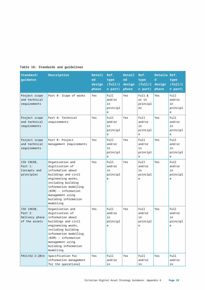
StandardsIdentify/nominate the specific standards and guidelines to be followed by all project participants to apply best practises for digital engineering and project execution. Consideration or adoption of any other standards related to digital engineering must be identified, discussed and agreed in writing with the DE Lead prior to implementation for any project.
Appointing Party standardsThis section should articulate relevant standards, e.g. CAD standard, drawing numbering, BIM standard, GIS standard, asset data loading templates etc.
Table 16: Standards and guidelines
Standard/ guidance
Description Detailed design phase
Ref. type (full/in part)
Detailed design phase
Ref. type (full/in part)
Detailed design phase
Ref. type (full/in part)
Project scope and Part #: Scope of works Yes Full Yes Full & or Yes Full
Victorian Digital Asset Strategy Guidance: Appendix 6 Page 15
technical requirements
and/or in principle
in principles
and/or in principle
Project scope and technical requirements
Part #: Technical requirements
Yes Full and/or in principle
Yes Full and/or in principle
Yes Full and/or in principle
Project scope and technical requirements
Part #: Project management requirements
Yes Full and/or in principle
Yes Full and/or in principle
Yes Full and/or in principle
ISO 19650, Part 1: Concepts and principles
Organisation and digitisation of information about buildings and civil engineering works, including building information modelling (BIM) – information management using building information modelling
Yes Full and/or in principle
Yes Full and/or in principle
Yes Full and/or in principle
ISO 19650, Part 2: Delivery phase of the assets
Organisation and digitisation of information about buildings and civil engineering works, including building information modelling (BIM) – information management using building information modelling
Yes Full and/or in principle
Yes Full and/or in principle
Yes Full and/or in principle
PAS1192-3:2014 Specification for information management for the operational phase of construction projects using building information modelling
Yes Full and/or in principle
Yes Full and/or in principle
Yes Full and/or in principle
BIMForum LOD 2018 – Spec Part 1 and Guide 2018
Level of development (LOD) specification Part I and Commentary For Building Information Models and Data September 2018
Yes Full and/or in principle
Yes Full and/or in principle
Yes Full and/or in principle
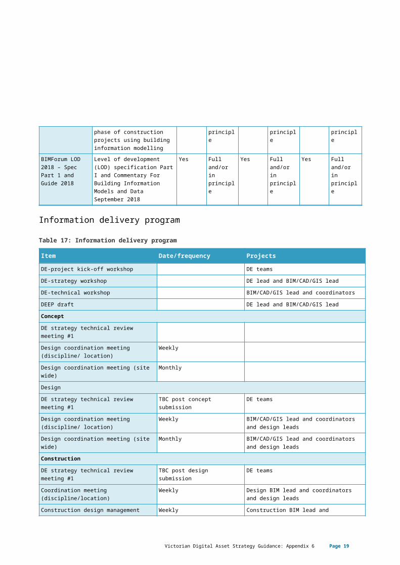
Information delivery program
Table 17: Information delivery program
Item Date/frequency ProjectsDE-project kick-off workshop DE teamsDE-strategy workshop DE lead and BIM/CAD/GIS leadDE-technical workshop BIM/CAD/GIS lead and coordinatorsDEEP draft DE lead and BIM/CAD/GIS leadConcept
Victorian Digital Asset Strategy Guidance: Appendix 6 Page 16
Item Date/frequency ProjectsDE strategy technical review meeting #1Design coordination meeting (discipline/ location)
Weekly
Design coordination meeting (site wide) MonthlyDesignDE strategy technical review meeting #1 TBC post concept submission DE teamsDesign coordination meeting (discipline/ location)
Weekly BIM/CAD/GIS lead and coordinators and design leads
Design coordination meeting (site wide) Monthly BIM/CAD/GIS lead and coordinators and design leads
Construction
DE strategy technical review meeting #1 TBC post design submission DE teamsCoordination meeting (discipline/location)
Weekly Design BIM lead and coordinators and design leads
Construction design management meeting
Weekly Construction BIM lead and construction design package leads
Coordination meeting (site wide) Monthly BIM/CAD/GIS lead and coordinators & design leads
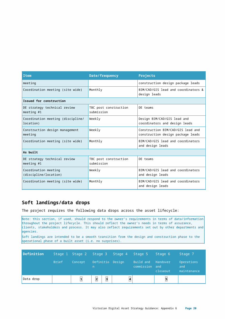
Issued for construction
DE strategy technical review meeting #1 TBC post construction submission
DE teams
Coordination meeting (discipline/ location)
Weekly Design BIM/CAD/GIS lead and coordinators and design leads
Construction design management meeting
Weekly Construction BIM/CAD/GIS lead and construction design package leads
Coordination meeting (site wide) Monthly BIM/CAD/GIS lead and coordinators and design leads
As built
DE strategy technical review meeting #1 TBC post construction submission
DE teams
Coordination meeting (discipline/location)
Weekly BIM/CAD/GIS lead and coordinators and design leads
Coordination meeting (site wide) Monthly BIM/CAD/GIS lead and coordinators and design leads
Soft landings/data dropsThe project requires the following data drops across the asset lifecycle:
Victorian Digital Asset Strategy Guidance: Appendix 6 Page 17
Note: this section, if used, should respond to the owner’s requirements in terms of data/information throughout the project lifecycle. This should reflect the owner’s needs in terms of assurance, clients, stakeholders and process. It may also reflect requirements set out by other departments and agencies.Soft landings are intended to be a smooth transition from the design and construction phase to the operational phase of a built asset (i.e. no surprises).
Definition Stage 1 Stage 2 Stage 3 Stage 4 Stage 5 Stage 6 Stage 7
Brief Concept Definition Design Build and commission
Handover and closeout
Operations and maintenance
Data drop 1 2 3 4 5
The above table should reflect the project timeline and needs as per the EIR.
The above data drops require the following information:
Victorian Digital Asset Strategy Guidance: Appendix 6 Page 18
The contents of table below should respond to the client’s soft-landing needs as noted in the EIR. The numbered boxes above should cross reference the table below.
Data drop
Description
1 When: DD MMM YYYYMethodology: Desktop assessment based on submitted information, supplemented by conversations with project team to clarify any matters.Submission details: completed project statement of intent, including key contacts and dates; design statement in line with XX, and a note of the persons (name and role) involved in the
development of the statement – i.e. those stakeholders represented in the development of both the agreed non-negotiables and the benchmarks;
initial list of relevant design guidance to be followed – XX, YY, ZZ; assessment of current OIR and AIR; and assessment of how project will align with OIR and AIR.Format:Information to be provided in an agreed electronic format e.g. Word/PDF.
2 When: DD MMM YYYYMethodology: site feasibility studies and analysis of project options to inform a preliminary business case.Submission details: ≤ 1:1000 plot plans and drawings where a project is one of a series, or a major development, being considered for a site, a masterplan is
required to demonstrate the potential interaction on other services; analysis of site option(s) ( ≤ 1:500), in terms of potential for achieving the project’s non-negotiables
criteria and benchmarks established in the design statement and the inherent design risks (i.e. where the site presents difficulties in achieving the benchmarked standards); and
initial list of relevant design guidance to be followed – XX, YY, ZZ, Including a schedule of any key derogations.
Format: Information to be provided in an electronic format. Geometric models: proprietary 3D BIMs with 2D PDFs cut from the models to the above noted levels of definition/scales. Non-graphical information to be provided in an agreed electronic format e.g. Word/PDF.
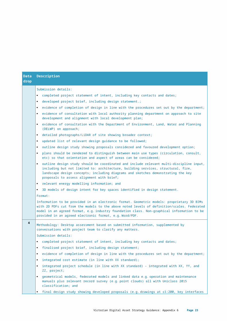
3 When: DD MMM YYYYMethodology: more rigorous feasibility study-based on site-confirmed information, basic engineering and detailed stakeholder engagement to clarify any matters.Submission details: completed project statement of intent, including key contacts and dates; developed project brief, including design statement.; evidence of completion of design in line with the procedures set out by the department; evidence of consultation with local authority planning department on approach to site development and
alignment with local development plan; evidence of consultation with the Department of Environment, Land, Water and Planning (DELWP) on
Victorian Digital Asset Strategy Guidance: Appendix 6 Page 19
Data drop
Description
approach; detailed photographs/LiDAR of site showing broader context; updated list of relevant design guidance to be followed; outline design study showing proposals considered and favoured development option; plans should be rendered to distinguish between main use types (circulation, consult, etc) so that
orientation and aspect of areas can be considered; outline design study should be coordinated and include relevant multi-discipline input, including but not
limited to: architecture, building services, structural, fire, landscape design concepts; including diagrams and sketches demonstrating the key proposals to assess alignment with brief;
relevant energy modelling information; and 3D models of design intent for key spaces identified in design statement.Format: Information to be provided in an electronic format. Geometric models: proprietary 3D BIMs with 2D PDFs cut from the models to the above noted levels of definition/scales. Federated model in an agreed format, e.g. industry foundation class. Non-graphical information to be provided in an agreed electronic format, e.g. Word/PDF.
4 When: DD MMM YYYYMethodology: Desktop assessment based on submitted information, supplemented by conversations with project team to clarify any matters.Submission details: completed project statement of intent, including key contacts and dates; finalised project brief, including design statement; evidence of completion of design in line with the procedures set out by the department; integrated cost estimate (in line with XX standard); integrated project schedule (in line with XX standard) – integrated with XX, YY, and ZZ, project; geometrical models, federated models and linked data e.g. operation and maintenance manuals plus
relevant record survey (e.g. point clouds) all with Uniclass 2015 classification; and final design study showing developed proposals (e.g. drawings at ≤1:200, key interfaces at ≤1:50, plus
key elements ≤1:20 ). Key drawings, (construction details/specs need not be submitted) including:– site layout showing wider context and landscape proposals; – plans rendered to distinguish between use types (circulation, consult);– elevations/sections showing design in context;– building services report and layouts;– structural/civil report and layouts;– landscape report and layouts;– specialist report and layouts;– 3D visualisations of the building in context – including key approaches perspectives from a human
eye height; and– confirmation of planning permission and building regulation compliance.
Format: Information to be provided in an electronic format. Geometric models: proprietary 3D BIMs with 2D PDFs cut from the models to the above noted levels of definition/scales. Federated model in an agreed format, e.g. industry foundation class. Non-graphical information to be provided in an agreed electronic format
Victorian Digital Asset Strategy Guidance: Appendix 6 Page 20

Data drop
Description
e.g. Word/PDF.
5 When: DD MMM YYYYMethodology: As-built graphical and non-graphical project information and key information handover to the operator, facilities manager and maintenance manager.Submission details: geometrical models, federated models and linked data, e.g. operation and maintenance manuals plus
relevant record survey (e.g. point clouds), all with Uniclass 2015 classification; geometrical models to be correct with the following tolerances:
– mechanical: +/- XX mm;– electrical: +/- XX mm;– architecture +/- XX mm;– etc.
linked data, e.g. operation and maintenance manuals plus relevant record survey (e.g. point clouds), all with Uniclass 2015 classification;
detailed asset register as per (XX YY standard) – validated by third-party; retention of native federated project model for XX years with client access; and handover of planning-critical information to DELWP via XX.Format: Information to be provided in an electronic format. Geometric models: proprietary 3D BIMs with 2D PDFs cut from the models to the above noted levels of definition/scales. Federated model in an agreed format, e.g. industry foundation class. Non-graphical information to be provided in an agreed electronic format, e.g. Word/PDF.
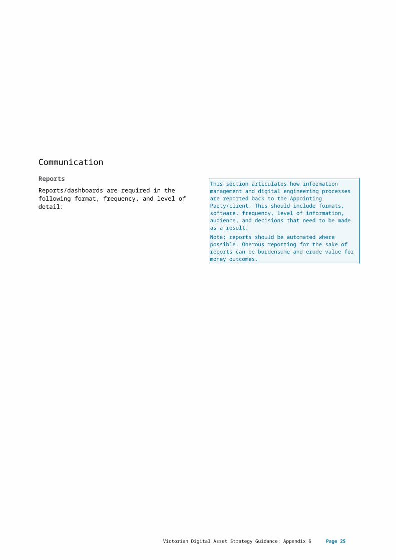
CommunicationReportsReports/dashboards are required in the following format, frequency, and level of detail:
This section articulates how information management and digital engineering processes are reported back to the Appointing Party/client. This should include formats, software, frequency, level of information, audience, and decisions that need to be made as a result. Note: reports should be automated where possible. Onerous reporting for the sake of reports can be burdensome and erode value for money outcomes.
Victorian Digital Asset Strategy Guidance: Appendix 6 Page 21
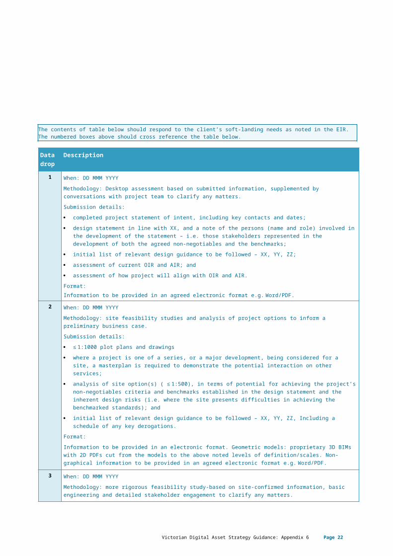
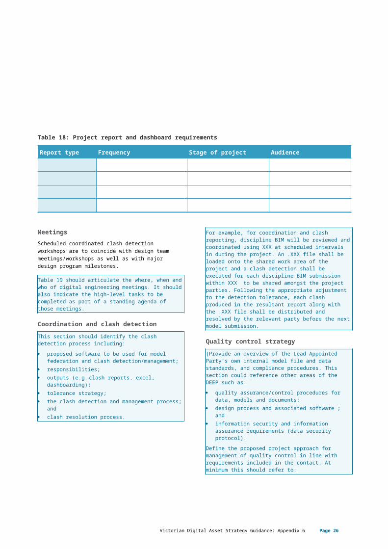
Table 18: Project report and dashboard requirements
Report type Frequency Stage of project Audience
MeetingsScheduled coordinated clash detection workshops are to coincide with design team meetings/workshops as well as with major design program milestones.
Table 19 should articulate the where, when and who of digital engineering meetings. It should also indicate the high-level tasks to be completed as part of a standing agenda of those meetings.
Coordination and clash detectionThis section should identify the clash detection process including: proposed software to be used for model federation
and clash detection/management; responsibilities; outputs (e.g. clash reports, excel, dashboarding); tolerance strategy; the clash detection and management process; and clash resolution process. For example, for coordination and clash reporting, discipline BIM will be reviewed and coordinated using XXX at scheduled intervals in during the project. An .XXX file shall be loaded onto the shared work area of the project and a clash detection shall be executed for each discipline BIM submission within XXX to be shared amongst the project parties. Following the appropriate adjustment to the detection tolerance, each clash produced in the resultant report along with the .XXX file shall be distributed and resolved by the relevant party before the next model submission.
Quality control strategy[Provide an overview of the Lead Appointed Party’s own internal model file and data standards, and compliance procedures. This section could reference other areas of the DEEP such as: quality assurance/control procedures for data,
models and documents; design process and associated software ; and information security and information assurance
requirements (data security protocol).Define the proposed project approach for management of quality control in line with requirements included in the contact. At minimum this should refer to: establishment and use of suitable procedures for
quality assurance and data control for both issuing and receiving of data;
throughout the life of the project it will be necessary to audit the digital engineering environment and its constituent models to maintain consistency of approach to digital engineering, data management, adherence to the contract and to establish software and hardware issues that require attention. These audits will take place at regular intervals. The frequency of these audits will be discussed, agreed and recorded in the final DEEP. The audits will be undertaken by the DE Lead, BIM and GIS Leads, who in turn will issue a report to all members of the design team for comment and action; and
the Lead Appointed Party DE Lead is responsible for closing out the actions identified in the audit and will be expected to elevate any issues beyond the control of the Project Delivery Team to the DE Project Champion.
Victorian Digital Asset Strategy Guidance: Appendix 6 Page 22
Quality control checks Quality control checks are required at each project stage. Please define which checks will be performed at which stages in Table 19.
Table 19: Quality control checks
Checks Definition Stages (SD, DD, CD, IFC)
Responsible party
Software program(s)
Visual check Ensure there are no unintended model components, and that they are correctly located in x, y, z, and coordination of the model against elements within the same model has occurred.
SD, DD, CD, IFC
Interference check
Detect problems in the model where two components are clashing, including soft and hard clashes.
DD, CD, IFC
Standards check
Ensure that the BIM/CAD standards and EIR have been followed (fonts, dimensions, line styles, levels/layers, room names, embedded data, etc.).
SD, DD, CD, IFC
Model integrity checks
Describe the QC validation process used to ensure that the BIM has no undefined, incorrectly defined or duplicated elements and the reporting process on non-compliant elements and corrective action plans.
DD, CD, IFC
Model accuracy
Validate the completeness of the model, ensuring all appropriate dimensioning as needed for design intent, analysis and construction are included in the model.
DD, CD, IFC
Data validation Check the information that is attributed to the object(s) has the correct values for the stage of the project.
DD, CD, IFC
2D output Check the 3D against 2D output (e.g. drawings and schedules against modelled elements).
DD, CD, IFC
Asset data check
Check the information that is attributed to the object(s) has been exported correctly to the asset data spreadsheet (e.g. COBie) and has the correct values for the stage of the project.
CD, IFC, As built
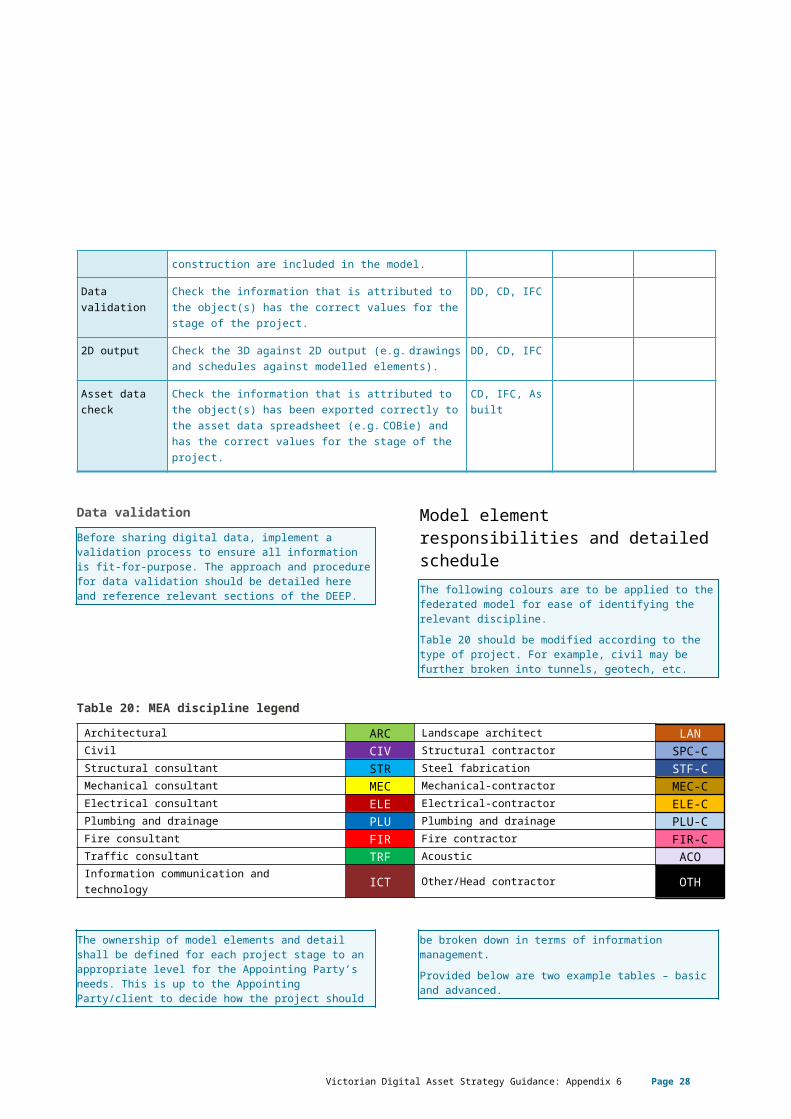
Data validationBefore sharing digital data, implement a validation process to ensure all information is fit-for-purpose. The approach and procedure for data validation should be detailed here and reference relevant sections of the DEEP.
Model element responsibilities and detailed scheduleThe following colours are to be applied to the federated model for ease of identifying the relevant discipline.
Victorian Digital Asset Strategy Guidance: Appendix 6 Page 23
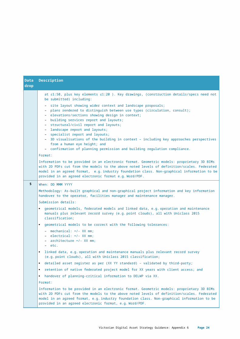
Table 20 should be modified according to the type of project. For example, civil may be further broken into tunnels, geotech, etc.
Table 20: MEA discipline legendArchitectural ARC Landscape architect LANCivil CIV Structural contractor SPC-CStructural consultant STR Steel fabrication STF-CMechanical consultant MEC Mechanical-contractor MEC-CElectrical consultant ELE Electrical-contractor ELE-CPlumbing and drainage PLU Plumbing and drainage PLU-CFire consultant FIR Fire contractor FIR-CTraffic consultant TRF Acoustic ACOInformation communication and technology ICT Other/Head contractor OTH
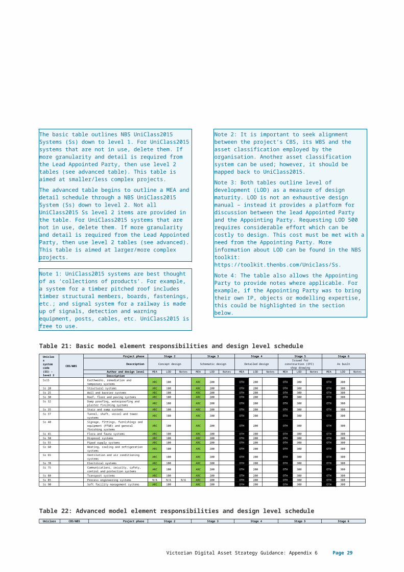
The ownership of model elements and detail shall be defined for each project stage to an appropriate level for the Appointing Party’s needs. This is up to the Appointing Party/client to decide how the project should be broken down in terms of information management. Provided below are two example tables – basic and advanced. The basic table outlines NBS UniClass2015 Systems (Ss) down to level 1. For UniClass2015 systems that are not in use, delete them. If more granularity and detail is required from the Lead Appointed Party, then use level 2 tables (see advanced table). This table is aimed at smaller/less complex projects.The advanced table begins to outline a MEA and detail schedule through a NBS UniClass2015 System (Ss) down to level 2. Not all UniClass2015 Ss level 2 items are provided in the table. For UniClass2015 systems that are not in use, delete them. If more granularity and detail is required from the Lead Appointed Party, then use level 2 tables (see advanced). This table is aimed at larger/more complex projects.
Note 1: UniClass2015 systems are best thought of as ‘collections of products’. For example, a system for a timber pitched roof includes timber structural members, boards, fastenings, etc.; and signal system for a railway is made up of signals, detection and warning equipment, posts, cables, etc. UniClass2015 is free to use.Note 2: It is important to seek alignment between the project’s CBS, its WBS and the asset classification employed by the organisation. Another asset classification system can be used; however, it should be mapped back to UniClass2015.Note 3: Both tables outline level of development (LOD) as a measure of design maturity. LOD is not an exhaustive design manual – instead it provides a platform for discussion between the lead Appointed Party and the Appointing Party. Requesting LOD 500 requires considerable effort which can be costly to design. This cost must be met with a need from the Appointing Party. More information about LOD can be found in the NBS toolkit: https://toolkit.thenbs.com/Uniclass/Ss.Note 4: The table also allows the Appointing Party to provide notes where applicable. For example, if the Appointing Party was to bring their own IP, objects or modelling expertise, this could be highlighted in the section below.
Table 21: Basic model element responsibilities and design level scheduleUniclass system code (SS) – level 2
CBS/WBS
Project phase Stage 2 Stage 3 Stage 4 Stage 5 Stage 6
Description Concept design Schematic design Detailed designIssued for construction
(IFC) shop drawing
As built
Author and design level MEA LOD Notes MEA LOD Notes MEA LOD Notes MEA LOD Notes MEA LOD NotesDescription
Ss15 Earthworks, remediation and temporary systems ARC 100 ARC 200 OTH 200 OTH 300 OTH 300
Ss 20 Structural systems ARC 100 ARC 200 OTH 200 OTH 300 OTH 300
Victorian Digital Asset Strategy Guidance: Appendix 6 Page 24
Ss 25 Wall and barrier systems ARC 100 ARC 200 OTH 200 OTH 300 OTH 300Ss 30 Roof, floor and paving systems ARC 100 ARC 200 OTH 200 OTH 300 OTH 300Ss 32 Damp proofing, waterproofing and
plaster finishing systems ARC 100 ARC 200 OTH 200 OTH 300 OTH 300Ss 35 Stair and ramp systems ARC 100 ARC 200 OTH 200 OTH 300 OTH 300Ss 37 Tunnel, shaft, vessel and tower systems ARC 100 ARC 200 OTH 200 OTH 300 OTH 300Ss 40 Signage, fittings, furnishings and
equipment (FF&E) and general finishing systems
ARC 100 ARC 200 OTH 200 OTH 300 OTH 300
Ss 45 Flora and fauna systems ARC 100 ARC 200 OTH 200 OTH 300 OTH 300Ss 50 Disposal systems ARC 100 ARC 200 OTH 200 OTH 300 OTH 300Ss 55 Piped supply systems ARC 100 ARC 200 OTH 200 OTH 300 OTH 300Ss 60 Heating, cooling and refrigeration
systems ARC 100 ARC 200 OTH 200 OTH 300 OTH 300Ss 65 Ventilation and air conditioning systems ARC 100 ARC 200 OTH 200 OTH 300 OTH 300Ss 70 Electrical systems ARC 100 ARC 200 OTH 200 OTH 300 OTH 300Ss 75 Communications, security, safety, control
and protection systems ARC 100 ARC 200 OTH 200 OTH 300 OTH 300Ss 80 Transport systems ARC 100 ARC 200 OTH 200 OTH 300 OTH 300Ss 85 Process engineering systems N/A N/A N/A ARC 200 OTH 200 OTH 300 OTH 300Ss 90 Soft facility management systems ARC 100 ARC 200 OTH 200 OTH 300 OTH 300
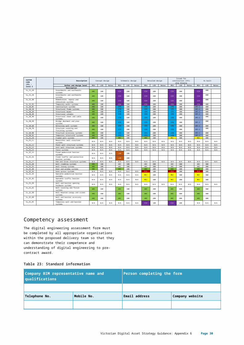
Table 22: Advanced model element responsibilities and design level scheduleUniclass system code (SS) – level 2
CBS/WBS Project phase Stage 2 Stage 3 Stage 4 Stage 5 Stage 6Description Concept design Schematic design Detailed design Issued for construction
(IFC) shop drawing As builtAuthor and design level MEA LOD Notes MEA LOD Notes MEA LOD Notes MEA LOD Notes MEA LOD NotesDescription
Ss_15_10 Groundworks and earthworks systems ARC 100 CIV 100 CIV 200 CIV 300 CIV 400
Ss_15_10 Groundworks and earthworks systems ARC 100 CIV 100 CIV 200 CIV 300 CIV 400
Ss_15_30 Remediation, repair and renovation systems ARC 100 CIV 100 CIV 200 CIV 300 CIV 400
Ss_15_95 Temporary works systems ARC 100 CIV 100 CIV 200 CIV 300 CIV 400Ss_20_05 Substructure systems ARC 100 STR 100 STR 200 STR 300 SPC-C 400Ss_20_10 Structural frame systems ARC 100 STR 100 STR 200 STR 300 SPC-C 400Ss_20_20 Structural beams ARC 100 STR 100 STR 200 STR 300 SPC-C 400Ss_20_30 Structural columns ARC 100 STR 100 STR 200 STR 300 SPC-C 400Ss_20_40 Structural sheet and cable systems ARC 100 STR 100 STR 200 STR 300 SPC-C 400Ss_20_50 Bridge abutment and pier systems ARC 100 STR 100 STR 200 STR 300 SPC-C 400Ss_20_60 Retaining wall systems ARC 100 STR 100 STR 200 STR 300 SPC-C 400Ss_20_70 Structure covering and finishing
systems ARC 100 STR 100 STR 200 STR 300 SPC-C 400
Ss_20_80 Structure accessory systems ARC 100 STR 100 STR 200 STR 300 SPC-C 400Ss_20_95 Temporary structural systems ARC 100 STR 100 STR 200 STR 300 SPC-C 400Ss_25_10 Framed wall systems ARC 100 ARC 100 ARC 200 MEC 300 MEC 400Ss_25_11 Monolithic wall structure systems N/A N/A N/A N/A N/A N/A N/A N/A N/A N/A N/A N/A N/A N/A N/ASs_25_12 Panel wall structure systems N/A N/A N/A N/A N/A N/A N/A N/A N/A N/A N/A N/A N/A N/A N/ASs_25_13 Unit wall structure systems N/A N/A N/A N/A N/A N/A N/A N/A N/A N/A N/A N/A N/A N/A N/ASs_25_14 Fence systems N/A N/A N/A N/A N/A N/A N/A N/A N/A N/A N/A N/A N/A N/A N/ASs_25_15 Fixed pedestrian barrier systems N/A N/A N/A LAN 100Ss_25_16 Fixed traffic and protective barrier
systems N/A N/A N/A LAN 100Ss_25_17 Dam and levee structure systems N/A N/A N/A N/A N/A N/A N/A N/A N/A N/A N/A N/A N/A N/A N/ASs_25_20 Wall cladding systems ARC 100 ARC 100 ARC 200 ARC 300 ARC 300Ss_25_25 Wall lining systems ARC 100 ARC 100 ARC 200 ARC 300 ARC 300Ss_25_30 Door and window systems ARC 100 ARC 100 ARC 200 ARC 300 ARC 300Ss_25_32 Gate access systems N/A N/A N/A N/A N/A N/A ELE 100 ELE 300 ELE 300Ss_25_34 Operable pedestrian barrier systems N/A N/A N/A N/A N/A N/A MEC 200 MEC 300 MEC 300Ss_25_36 Operable traffic barrier systems N/A N/A N/A N/A N/A N/A MEC 200 MEC 300 MEC 300Ss_25_38 Wall and barrier opening hardware
systems N/A N/A N/A N/A N/A N/A N/A N/A N/A N/A N/A N/A N/A N/A N/ASs_25_45 Wall covering and finish systems ARC 100 ARC 100 ARC 200 ARC 300 ARC 300Ss_25_50 Wall mounted canopy and screen
systems ARC 100 ARC 100 ARC 200 ARC 300 ARC 300Ss_25_60 Wall and barrier accessory systems ARC 100 ARC 100 ARC 200 ARC 300 ARC 300Ss_25_95 Temporary wall and barrier systems N/A N/A N/A N/A N/A N/A CIV 100 CIV 100 N/A N/A N/A
Competency assessmentThe digital engineering assessment form must be completed by all appropriate organisations within the proposed delivery team so that they can demonstrate their competence and understanding of digital engineering to pre-contract award.
Table 23: Standard information
Company BIM representative name and qualifications
Person completing the form
Victorian Digital Asset Strategy Guidance: Appendix 6 Page 25
Telephone No. Mobile No. Email address Company website
Table 24: BIM gateway questions
No. Question Answer Supporting evidence (if applicable)
G1.1 Confirm that the delivery team are prepared to issue native BIM format files?
G1.2 Does the delivery team apply strict disclaimers to issued BIM files that may restrict the ‘uses’ of the BIM process?
G2.1 Does the delivery team work to a digital engineering standard or guideline? If yes, what is it?
G2.2 Does the delivery team understand the level of development that is required at each of the project delivery stages?
G2.3 Does the delivery team understand the level of information that is required at each of the project delivery stages?
G2.4 How does the delivery team demonstrate (or what measures are in place to ensure) compliance with the digital engineering standards?
G3.1 Are the delivery team prepared to comply with the contents of the EIR?
G3.2 Are there any risks or issues that may affect the delivery team ability to comply with the contents of the EIR?
G4 In the delivery team’s experience, how does BIM support the safety in design process?
G5 In a single paragraph please explain the delivery team’s experience with linked, attached and embedded attribute data within 3D models.
G6 Has the delivery team used classification systems with BIM, such as Uniclass etc.
G7 Has the delivery team used 4D tools and process, e.g. construction sequencing?
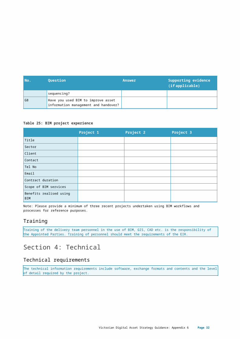
G8 Have you used BIM to improve asset information management and handover?
Victorian Digital Asset Strategy Guidance: Appendix 6 Page 26
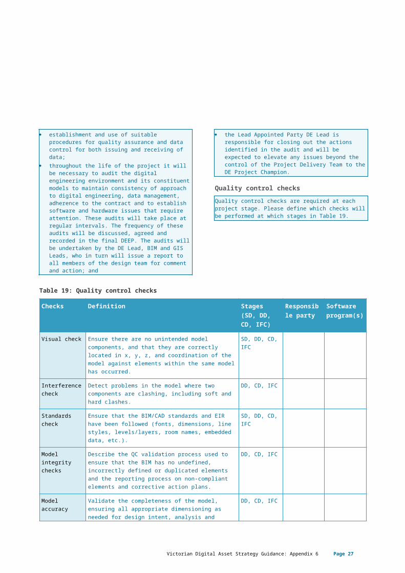
Table 25: BIM project experience
Project 1 Project 2 Project 3TitleSectorClientContactTel NoEmailContract durationScope of BIM servicesBenefits realised using BIM
Note: Please provide a minimum of three recent projects undertaken using BIM workflows and processes for reference purposes.
TrainingTraining of the delivery team personnel in the use of BIM, GIS, CAD etc. is the responsibility of the Appointed Parties. Training of personnel should meet the requirements of the EIR.
Section 4: TechnicalTechnical requirementsThe technical information requirements include software, exchange formats and contents and the level of detail required by the project.
Table 26: Technical requirements
Item Description Information requirementsClient Contractor
Software platforms Define the platform for the building information model as well as other software platforms to be used. The purpose of this section is to communicate software platforms and versions where these are known and where they might influence the preparation of a bid.
Data exchange format
The purpose of this section is to define the formats used to deliver data at various project stages.
Project coordinates The purpose of this section is to mandate the adoption of a common coordinate system for all BIM data with consistent adoption for all models.
Level of detail The purpose of this section is to define the requirements for information at project stages.
Training The purpose of this section is to provide details of training that will be provided in connection with project
Victorian Digital Asset Strategy Guidance: Appendix 6 Page 27
systems, or training requirements which the stakeholder group will be required to deliver as part of their appointment.
Asset information requirementsDefine the project specific asset information requirements. This could reference elements of the organisation-wide asset information requirements, the exchange information requirements, an external asset data model or be provided through an asset data loading spreadsheet.
Asset classification Uniclass 2015 is structured into a hierarchical set of tables ranging from the broadest view of assets to the most detailed components. The main tables for broad classification include complexes, entities, spaces and activities, as shown in the following figure.The contractor shall describe the application of asset classification as per the project-specific requirements, i.e. UniClass 2015 classification system and hierarchy.
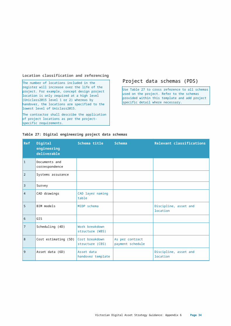
Location classification and referencingThe number of locations included in the register will increase over the life of the project. For example, concept design project location is only required at a high level (Uniclass2015 level 1 or 2) whereas by handover, the locations are specified to the lowest level of Uniclass2015.The contractor shall describe the application of project locations as per the project-specific requirements.
Project data schemas (PDS)Use Table 27 to cross reference to all schemas used on the project. Refer to the schemas provided within this template and add project specific detail where necessary.
Table 27: Digital engineering project data schemas
Ref Digital engineering deliverable
Schema title Schema Relevant classifications
1 Documents and correspondence
2 Systems assurance
3 Survey
4 CAD drawings CAD layer naming table
Victorian Digital Asset Strategy Guidance: Appendix 6 Page 28
5 BIM models MIDP schema Discipline, asset and location
6 GIS
7 Scheduling (4D) Work breakdown structure (WBS)
8 Cost estimating (5D) Cost breakdown structure (CBS)
As per contract payment schedule
9 Asset data (6D) Asset data handover template
Discipline, asset and location
Victorian Digital Asset Strategy Guidance: Appendix 6 Page 29
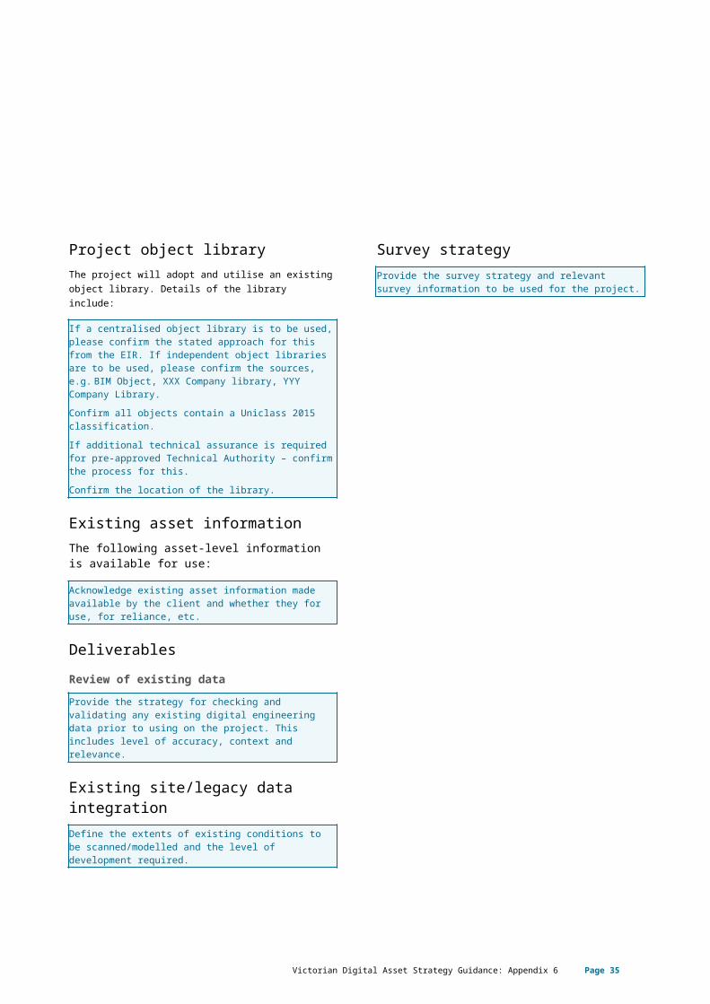
Project object libraryThe project will adopt and utilise an existing object library. Details of the library include:
If a centralised object library is to be used, please confirm the stated approach for this from the EIR. If independent object libraries are to be used, please confirm the sources, e.g. BIM Object, XXX Company library, YYY Company Library. Confirm all objects contain a Uniclass 2015 classification.If additional technical assurance is required for pre-approved Technical Authority – confirm the process for this.Confirm the location of the library.
Existing asset informationThe following asset-level information is available for use:
Acknowledge existing asset information made available by the client and whether they for use, for reliance, etc.
DeliverablesReview of existing dataProvide the strategy for checking and validating any existing digital engineering data prior to using on the project. This includes level of accuracy, context and relevance.
Existing site/legacy data integrationDefine the extents of existing conditions to be scanned/modelled and the level of development required.
Survey strategyProvide the survey strategy and relevant survey information to be used for the project.
Victorian Digital Asset Strategy Guidance: Appendix 6 Page 30
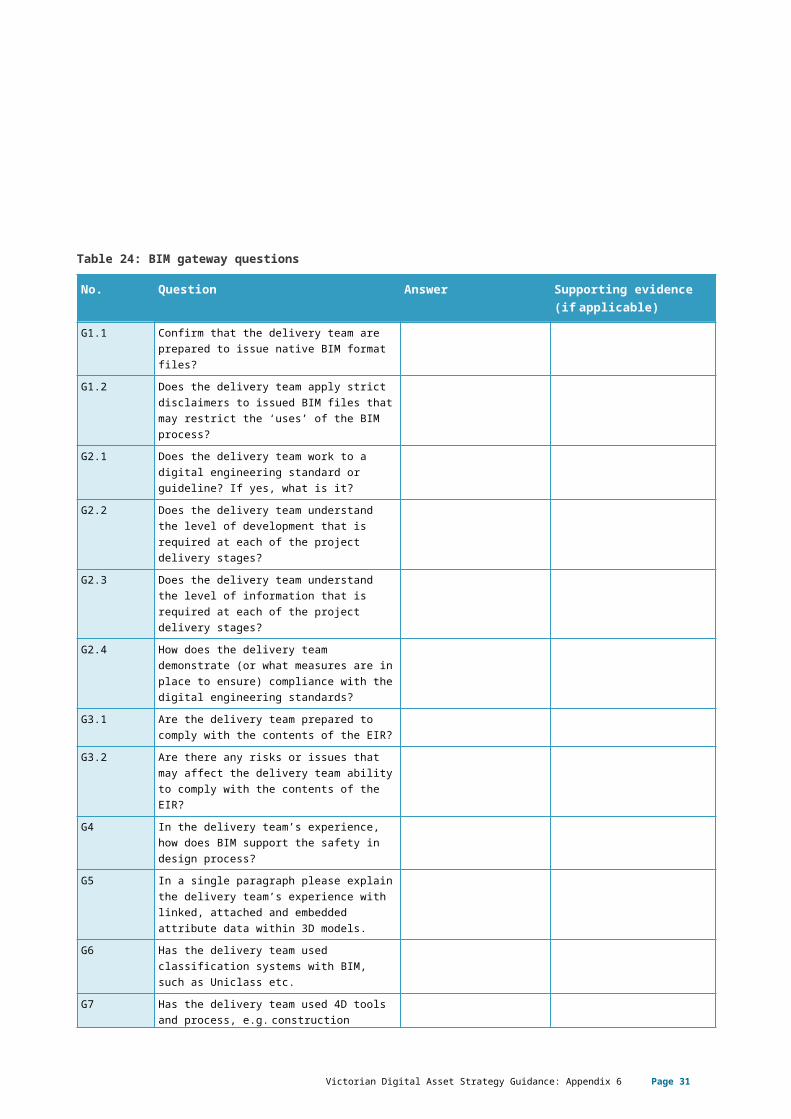
Table 28: Survey strategy
Survey method Delivery format Survey origin Details/notes
Feature survey
Point cloud
Light detecting and ranging (LIDAR)
Global navigation satellite systems (GNSS)
Utility mapping
Victorian Digital Asset Strategy Guidance: Appendix 6 Page 31
Digital survey deliverablesDetail what survey deliverables are to be provided to support the requirements of the contract, including the level of accuracy. Refer to the EIR for survey deliverable requirements.
CAD layer namingProvide the strategy and process for mapping CAD layers in accordance with the EIR, as well as the metadata schema.
CAD deliverablesProvide details of what CAD deliverables are to be provided to support the requirements of the contract.
BIM deliverablesPlease state how the model is to be coordinated across disciplines and the formats in which they will be submitted as specified by the client.
GIS deliverablesProvide the strategy for how GIS will assist the project with spatial analysis, graphical representation of information, and overall collaboration. This includes the following: how the georeferenced positions will be
represented and located; what the relationship is to the other CAD systems
being used; and how coordinates are associated.
Model data property requirementsEnter here properties that are to be included in each of the models, including what equivalent industry foundation class (IFC) properties are being used.
Systems engineering deliverablesIf digital engineering is to be used to demonstrate requirements management (systems assurance), detail here the procedure and information requirements to demonstrate traceability of the business requirements specification (BRS) and/or system requirements specification (SRS).
3D geometric deliverables – design and construction model(s)The design team is to ensure that the design model(s) remain updated throughout the design and construction phase and align with all issued drawings submitted as specified in issued for construction (IFC) drawings.
The contractor is to provide the client with consolidated as-build models for all elements of the project. The model should remain updated throughout the construction phase and should align with all issued drawings submitted as specified in the IFC drawings.
Please state how the model is to be coordinated across disciplines and the formats in which they will be submitted as specified by the client.
Scheduling (4D) deliverablesEnter here the strategy and details for scheduling, construction sequencing and simulation in alignment with the project requirements. This includes the following: file formats to be submitted, and whether they are
compatible with the CDE; the schedule management plan; how the scheduling will be simulated with models
on the project; alignment strategy with each of the different
project phases; and any other scheduling requirements for the project.
Victorian Digital Asset Strategy Guidance: Appendix 6 Page 32

Cost (5D) deliverablesProvide information on the strategy for cost simulation, and alignment to the metadata schema in line with the project’s cost plan. This includes the following: the cost breakdown structure; and the strategy for aligning costs with the schedule.
Detailed design drawingsThe design consultants, contractor, and its subcontractors must utilise building information modelling (BIM) to produce the detailed design documentation.
List all proposed detailed design drawing deliverables for this project in the task information delivery plan (TIDP) and collate in the master information delivery plan (MIDP), update post award.
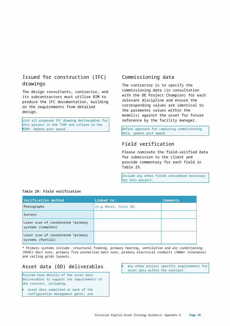
Issued for construction (IFC) drawingsThe design consultants, contractor, and its subcontractors must utilise BIM to produce the IFC documentation, building on the requirements from detailed design.
List all proposed IFC drawing deliverables for this project in the TIDP and collate in the MIDP. Update post award.
Commissioning dataThe contractor is to specify the commissioning data (in consultation with the DE Project Champion) for each relevant discipline and ensure the corresponding values are identical to the parameter values within the model(s) against the asset for future reference by the facility manager.
Define approach for capturing commissioning data, update post award.
Field verificationPlease nominate the field-verified data for submission to the client and provide commentary for each field in Table 29.
Include any other fields considered necessary for this project.
Table 29: Field verification
Verification method Linked to: CommentsPhotographs (e.g. Revit, Civil 3D)
Surveys
Laser scan of coordinated *primary systems (Complete)
Laser scan of coordinated *primary systems (Partial)
* Primary systems include: structural framing, primary heating, ventilation and air conditioning (HVAC) duct runs, primary fire protection main runs, primary electrical conduits (50mm+ tolerance) and ceiling grids layouts.
Victorian Digital Asset Strategy Guidance: Appendix 6 Page 33
Asset data (6D) deliverablesProvide here details of the asset data deliverables to support the requirements of the contract, including: asset data submitted at each of the configuration
management gates; and any other project specific requirements for asset
data within the contract.
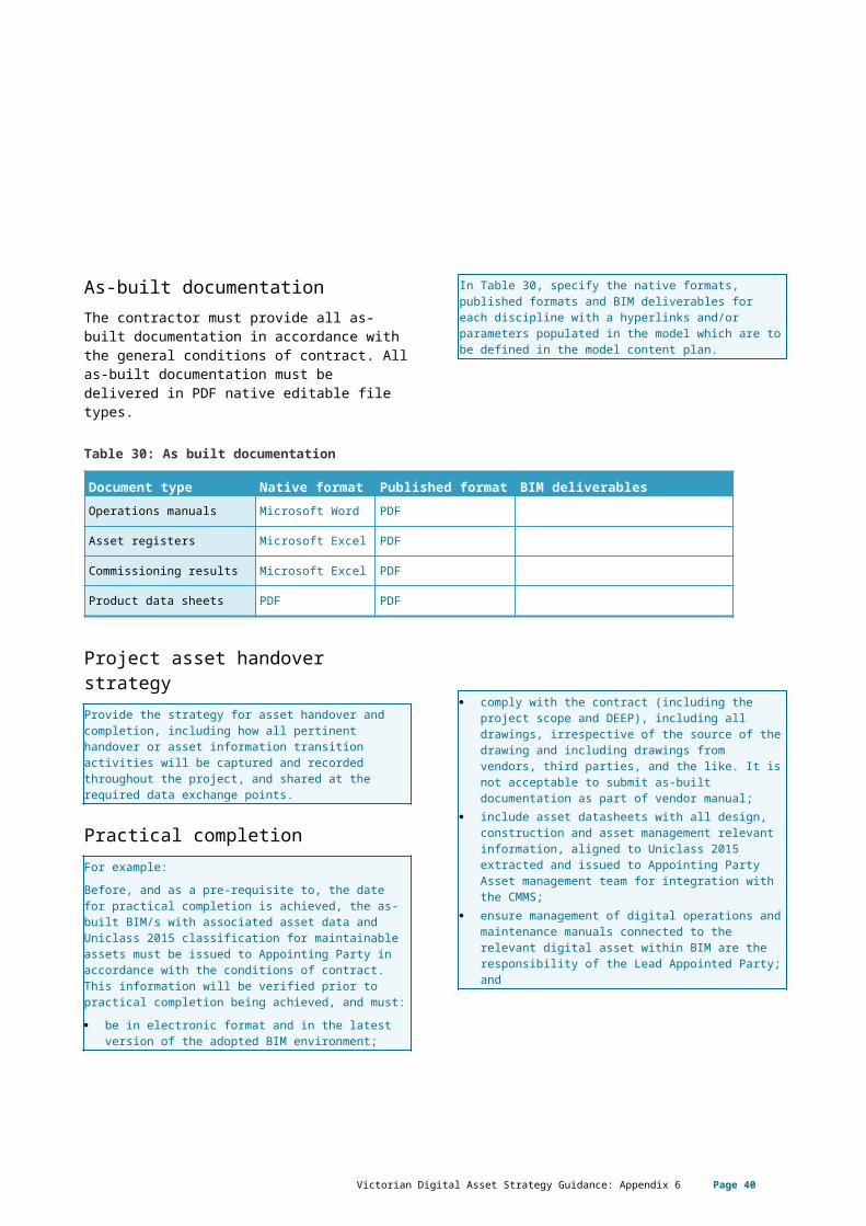
As-built documentationThe contractor must provide all as-built documentation in accordance with the general conditions of contract. All as-built documentation must be delivered in PDF native editable file types.
In Table 30, specify the native formats, published formats and BIM deliverables for each discipline with a hyperlinks and/or parameters populated in the model which are to be defined in the model content plan.
Table 30: As built documentation
Document type Native format Published format BIM deliverablesOperations manuals Microsoft Word PDF
Asset registers Microsoft Excel PDF
Commissioning results Microsoft Excel PDF
Product data sheets PDF PDF
Project asset handover strategyProvide the strategy for asset handover and completion, including how all pertinent handover or asset information transition activities will be captured and recorded throughout the project, and shared at the required data exchange points.
Practical completionFor example:Before, and as a pre-requisite to, the date for practical completion is achieved, the as-built BIM/s with associated asset data and Uniclass 2015 classification for maintainable assets must be issued to Appointing Party in accordance with the conditions of contract. This information will be verified prior to practical completion being achieved, and must: be in electronic format and in the latest version of
the adopted BIM environment;
comply with the contract (including the project scope and DEEP), including all drawings, irrespective of the source of the drawing and including drawings from vendors, third parties, and the like. It is not acceptable to submit as-built documentation as part of vendor manual;
include asset datasheets with all design, construction and asset management relevant information, aligned to Uniclass 2015 extracted and issued to Appointing Party Asset management team for integration with the CMMS;
ensure management of digital operations and maintenance manuals connected to the relevant digital asset within BIM are the responsibility of the Lead Appointed Party; and
build upon the construction model to a level of development (LOD) whereby the model element is graphically represented within the model as a specific system, object or assembly in terms of size, shape, location, quantity, and orientation with detailing, fabrication, assembly, commissioning and installation information, field verified.
Victorian Digital Asset Strategy Guidance: Appendix 6 Page 34
Non-graphic information may also be attached to the model element.
Hardware/technology infrastructure requirementsAll hardware in use by the delivery team shall have sufficient capacity to allow users to operate the models, undertake analysis and perform coordination and visualisation processes. The hardware specifications become valuable once information begins to be shared between several disciplines or organisations
Ensure that the downstream hardware is not less powerful than the hardware used to create the information (i.e. equal or higher). To aid hardware compatibility, choose high demand, appropriate hardware suited to most of the BIM uses specified on the project.In Table 31, indicate the hardware specifications nominated for use prior to, during or after BIM project delivery.
Table 31: Minimum hardware specifications
Specification Value
Processor speed:
Operating system:
Memory storage:
Graphics:
Network card:
Monitor(s)
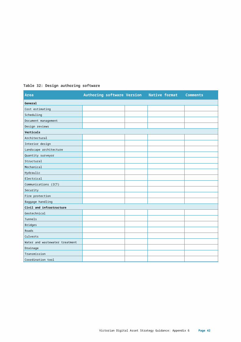
Software selection matrixThe contractor must utilise or interface with the owner in the following software platforms listed on the next page:
If applicable, nominate the preferred software to be used on this project in Table 32.
Victorian Digital Asset Strategy Guidance: Appendix 6 Page 35
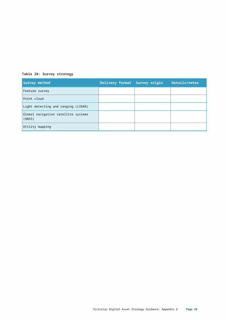
Table 32: Design authoring software
Area Authoring software
Version Native format Comments
General
Cost estimatingSchedulingDocument managementDesign reviewsVerticals
Architectural Interior designLandscape architectureQuantity surveyorStructural Mechanical Hydraulic Electrical Communications (ICT)SecurityFire protection Baggage handlingCivil and infrastructure
GeotechnicalTunnelsBridgesRoads CulvertsWater and wastewater treatmentDrainageTransmissionCoordination tool
Victorian Digital Asset Strategy Guidance: Appendix 6 Page 36
Software version update policyThe contractor must follow the following software update policy.
For example:Versioning of software must be managed by the Project BIM Manager throughout the project lifecycle.Any software version update(s) must be agreed with the delivery team across all disciplines/trades prior to updating. Once agreed, the nominated representative will endorse the upgrade. Only then will the BIM be upgraded. It is recommended that the timing of any updates should align with the end/start of project milestone dates to avoid disruption to the delivery team deliverables.
Data and exchange formatsData and exchange formats shall be developed in consideration of the most reliable and appropriate means of communicating data and information.
Provide details of your proposed Information exchange strategy.
Table 33: Exchange formats
Deliverable Stakeholder Software version
Native format Exchange format to CDE
Models
Drawings
Final drawing format
Schedules or spread sheets
Common data environment Information to be provided on the common data environment (CDE) should include: confirmation of collaboration tools; description of the validation process to be
implemented to ensure that all information, in regard to the intended use, meets client’s requirements;
folder structure; description of how work in progress, shared,
published and archived is to be used, including the sharing with other project stakeholders; and
proposed information flow, as well as frequency.
Project CDE requirementsEnter here the specific uses and features of the project CDE on the project.
File deliverablesEnter here any project specific requirements for all deliverables which will be uploaded into the project CDE.
Victorian Digital Asset Strategy Guidance: Appendix 6 Page 37
File metadata requirementsEnter here how the file metadata schema is to be utilised by the project team within the project CDE to help govern and control collaboration. Provide the metadata to be utilised, including: document numbering (unique ID); file naming; status and suitability; and revision and version control.
Naming conventionsAcknowledge the numbering system to be applied across projects as specified in the EIR.File naming identifies the project naming convention. Information contained in the table is taken from the project work breakdown structure.
Table 34: File naming
Project Zone/subzone Package Type Originator Discipline AWB Number
NEL 000 100 MLP CFS 100 000 0100
i.e. NEL-000-100-MLP-CFS-100-000-0100
Status and suitabilityProvide details on the method to be adopted for tracking the suitability and state of each document and model.
Revisions and versionsThe revision and version numbering of documents uploaded to the project CDE is to be documented below
Table 35: Information exchange program
Information exchange Project stakeholder Frequency Format
WIP design models Designers As required Native, IFC, Navisworks and Exchange.
Shared design models Designers Weekly (or at significant change)
Native, IFC, Navisworks and Exchange.
Published design models Designers Each stage gate Native, IFC, Navisworks and Exchange.
WIP federated models BIM Lead As required Navisworks federated models
Shared federated models BIM Lead Weekly (or at significant change)
Navisworks federated models
Victorian Digital Asset Strategy Guidance: Appendix 6 Page 38
Interfaces between CDEDefine the detailed workflows for sharing data and information between the Project CDE and Operational CDE, specifying any specific access or security requirements.Information shared with the owner must be uploaded to the CDE. Include in this section the process for review and approval of data prior to upload, and the upload process for the following: how the project CDE interfaces with the operational
CDE; and how the information is validated and migrated to
the Project CDE.
Level of development (LOD)Specify the LOD for each element that will be generated at each project milestone and information exchange to meet the specified BIM uses. The LOD and level of information (LOI) determine the extent and nature of geometry and data to be included within BIM objects. The extent of development required for elements or systems at various project stages will necessarily depend on the project procurement method to be used, as well as project-specific requirements. Elements must be modelled in accordance with LOD assignments defined in the DEEP.The different levels of development are defined below based on the BIM forum level of development specification.
Table 36: LOD definitions
Level of development
Model element
LOD 100 The model element may be graphically represented in the model with a symbol or other generic representation but does not satisfy the requirements for LOD 200. Information related to the model element (i.e. cost per square metre, tonnage of HVAC, etc.) can be derived from other model elements.Note: LOD 100 elements are not geometric representations. Examples are information attached to other model elements or symbols showing the existence of a component but not its shape, size, or precise location. Any information derived from LOD 100 elements must be considered approximate.
LOD 200 The model element is graphically represented within the model as a generic system, object, or assembly with approximate quantities, size, shape, location, and orientation. Non-graphic information may also be attached to the model element.Note: LOD 200 elements are generic placeholders. They may be recognisable as the components they represent, or they may be volumes for space reservation. Any information derived from LOD 200 elements must be considered approximate.
LOD 300 The model element is graphically represented within the model as a specific system, object or assembly in terms of quantity, size, shape, location, and orientation. Non-graphic information may also be attached to the model element.Note: The quantity, size, shape, location, and orientation of the element as designed can be measured directly from the model without referring to non-modelled information such as notes or dimension call-outs. The project origin is defined and the element is located accurately with respect to the project origin.
LOD 350 The model element is graphically represented within the model as a specific system, object, or assembly in terms of quantity, size, shape, location, orientation, and interfaces with other building systems. Non-graphic information may also be attached to the model element.Note: Parts necessary for coordination of the element with nearby or attached elements are
Victorian Digital Asset Strategy Guidance: Appendix 6 Page 39
Level of development
Model element
modelled. These parts will include such items as supports and connections. The quantity, size, shape, location and orientation of the element as designed can be measured directly from the model without referring to non-modelled information such as notes or dimension call-outs.
LOD 400 The model element is graphically represented within the model as a specific system, object or assembly in terms of size, shape, location, quantity, and orientation with detailing, fabrication, assembly, and installation information. Non-graphic information may also be attached to the model element.Note: An LOD 400 element is modelled at sufficient detail and accuracy for fabrication of the represented component. The quantity, size, shape, location, and orientation of the element as designed can be measured directly from the model without referring to non-modelled information such as notes or dimension call-outs.
LOD 500 The model element is a field verified representation in terms of size, shape, location, quantity, and orientation. Non-graphic information may also be attached to the model elements.Note. LOD 500 relates to field verification and is not an indication of progression to a higher level of model element geometry or non-graphic information.
Level of information needThe level of information about each asset class shall progressively be developed in the design and construction phases of the project for incorporation into the system.
Acknowledge the proposed approach for how information will be delivered from BIM into the CMMS (e.g. COBie) in line with the project stages.
Victorian Digital Asset Strategy Guidance: Appendix 6 Page 40
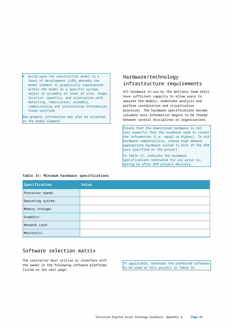
Table 37: Level of information need
LOI Level of information (non-graphical) Tagline
100 Generic identity and functionality of space and object
Sufficient for identification
200 Metadata for functionality of space and object, conditions of space, generic objectDetails of design calculation information, material specification, proposed generic object information
Sufficient for investigation
300 Specific identity and functionality of space and objectSpecific categorisationDesign specification and specified system performance information
Sufficiency for design
400 Specific Identity and Functionality of space and objectSpecific categorisationDesign specification and specified system performance informationSpecific manufacturer make and model
Sufficient for procurement
500 Specific identity and functionality of space and objectSpecific categorisationFurther data as per asset management requirements
Sufficient for management as per AM/OM requirements
Victorian Digital Asset Strategy Guidance: Appendix 6 Page 41
Page 42 Victorian Digital Asset Strategy Guidance Appendix 6: Digital engineering execution plan (DEEP)


![Asset Management Systems in Local Councils - Shoal Group · [1] Victorian Auditor-General’s Office, Asset Management and Maintenance by Councils, February 2014 [2] Victorian Auditor-General’s](https://img.pdfslide.net/doc/110x75/5ee002c8ad6a402d666b4625/asset-management-systems-in-local-councils-shoal-group-1-victorian-auditor-generalas.jpg)