Embed Size (px)
Citation preview

Ohms Law Worksheet Basic Circuits Name: _________________
Teacher: __________________Period:_____________________ Date:___________________
Circuit Symbol Key: MultimeterLight bulb A multimeter can
Measure measure theVoltage voltage or the
current. Examplesbelow show how tomeasure current or
Measure voltage and thecircuits that are
Light bulbs we are using in this lesson do not Current consistent with thehave a polarity, there is not + or - . pictures
Battery Switch
-The knife switch is a simple shorting mechanismIn this lesson we will be using D batteries. Note that inproviding a conductive connection when the lever isthe battery pictured above the right side is positive andlowered.the left is negative.
How to measure voltage: How to measure current:

Measure the voltage across a circuit element.Measure current by making the multimeter part of the circuit.

- -

Circuit Reference - Resistors in Series and ParallelOhm’s Law I Ohm’s Law relates the voltage across a component and the current
through a component given a resistance R.
V IR -Kirchhoff’s Voltage Law (KVL) Kirchhoff’s voltage law states that the sum of the voltage in a closed loop must add to zero. Using KVL we can show how resistors should add together when in series. Starting at the dot and moving clockwise we can add up the voltage or voltage drop across each component.
By convention if a component does note have a stated polarity it will be assumed to be positive.
Starting at the dot move clockwise-V1+VR1+VR2=0 →V1 = VR1+VR2 →
-V1 = IR1R1+IR2 R2 → -IR1=I R2 because current is constantV1 = I(R1+R2) →So Requiv = R1+R2
Kirchhoff’s Current Law (KCL) Kirchhoff’s current law states that the current into a node must be equal to the current exiting a node. KCL can be used to show how resistors add in parallel.

iin iR2
iR1
-
-
At the node the current from the battery comes in and gets split between R1 and R2.Iin-IR1-IR2=0 →Iin=IR1+IR2 →Iin = (VR1/R1)+(VR2 /R2) →VR1=V R2 =V1, because the voltage across both resistors is the same and equal to V1Iin = V1(1/R1+1/R2) →Iin = V1((R1+R2)/R1*R2) →Rearrange to look like Ohm’s LawV1 = I(R1*R2/(R1+R2)) →
SoR
equiv R1* R2R1R2

Diagram a Circuit
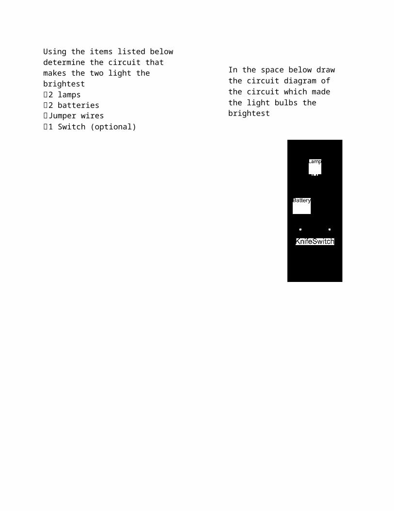
Using the items listed below determine the circuit that makes the two light the brightest 2 lamps 2 batteries Jumper wires 1 Switch (optional)
In the space below draw the circuit diagram of the circuit which madethe light bulbs the brightest

Brightest Lamp Circuit Diagram Symbol
Wire
In the circuit diagram above label each component in the diagram include expected voltage of each battery.
Use the multimeter to measure the voltage of the battery/batteries using the settings to the right:
(Place probes on either side of the battery determine the +/ - sides draw a picture of battery and equivalent circuit component with polarity)
Battery 1 ______________ (V)
Battery 2 ______________ (V)Only if both batteries are used
Using the values of the batteries from the circuit diagram what is thetotal voltage provided to the circuit.
Total Expected Voltage Supplied to Circuit VT= _______________(V) VT VM
% Diff 100[%]
VT
Measure the total voltage supplied to circuit

Total Measured Voltage Supplied to Circuit VM = ______________(V)

Lamps in Series - Measure the Voltage
side of the
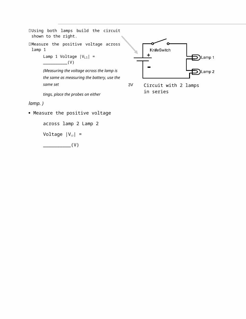
Using both lamps build the circuit shown to the right.
Measure the positive voltage across lamp 1 Lamp 1 Voltage |VL1| = __________(V)
(Measuring the voltage across the lamp is the same as measuring the battery, use the same set
tings, place the probes on either
lamp. )
Measure the positive voltage across lamp 2
Lamp 2 Voltage |VL2| = __________(V)
-Circuit with 2 lamps in series

Determine the polarity

Kirchhoff’s voltage law (KVL) Kirchhoff’s voltage law states that the sum of
the voltages in a closed loop must add to zero. Take the circuit to the right, if you start at the dot
and go clock wise you can write down the following equation.
-V1 +/- VR1 +/-VR2 = 0
We know the polarity or sign of the battery and if you think about walking around the circuit like you where walking on a path you would first see the negative side of the battery so you put a - in front of V1. By convention we apply a positive sign to circuit components when we do not know the polarity. So the equation above would be: -V1 + VR1 +VR2 = 0 or V1=VR1 +VR2
So we can label the polarity of each component as
Check: + =
VR1 VR2Is this close to
V1?
-
+ -+
- -

Using the convention above label the circuit to the right and measure the voltage across lamp 1
Lamp 1 Voltage VL1 = __________(V)
(Place the red probe on the plus side and the black
on the negative side )
Measure the voltage across lamp 2
Lamp 2 Voltage VL2 = __________(V)
-Circuit with 2 lamps in series

Lamps in Series -
Now that we know the voltage across each
lamp lets measure the current through each
lamp.
Voltage can be thought of as the potential of getting something done. You can also
think of voltage as a dam, the taller and
more water held back means there is
more potential energy available.
Current can be thought of as the flow of energy, in this case positive charge. Relating
current to water and the example above current can be thought of as the flow rate of
water.
With this information make a hypothesis about the current you expect to see through each
lamp (circle the one you agree with and explain why or propose another hypothesis).
1. Current through Lamp 1 > Current through Lamp 2
2. Current through Lamp 1 < Current through Lamp 2
3. Current through Lamp 1 = Current through Lamp 2
4. Current through Lamp 1 not related to Current through Lamp 2
5.
Why?
You know that to measure the current you have to include the multimeter into the circuit, draw two circuits below to measure the current in lamp 1 and lamp 2.
Measure the Current
-
Circuit with 2 lamps in series

Lamps in Series - Measure the Current Cont. Time to measure the current, start by changing the setting on the
multimeter to the ones shown in the picture to the right
Using the circuit diagram below measure the current through
each of the lamps.

-
(1) - Circuit to measure current in lamp 1
If you have the circuit built from the last page
disconnect the jumper wire that connected
lamp 1 to the switch.
Touch the red probe to the open end of the
switch.
Touch the black probe to the end of the
lamp 1 that is not connected to anything.
Record the current
Lamp 1 Current IL1 = __________ (A)
(where I is the standard symbol for
current and (A) stands for Amperes
which is C/s, or Coulombs per second.)
-
(2) - Circuit to measure current in lamp 2
From (1) reconnect lamp 1 to the switch
and disconnect the jumper connecting
the lamps together.
Touch the red probe to the
unconnected side of lamp 1.
Touch the black probe to the end of
the lamp 2 that does not connected to
anything.
Record the current
Lamp 2 Current IL2 = _________ (A)
(where I is the standard symbol for
current and (A) stands for Amperes

Compare the currents:
Was your hypothesis correct?

Lamps in Series - Put it Together
Ohm’s law states that the voltage is proportional to the resistance times the current or V=IR. Power dissipated by an electrical component found by multiplying the current times
the voltage or P=VI Look back at your previous work and record the voltage and current for each lamp in the spaces below.
X = = PL1
VL1 (V) IL1 (A) Lamp 1 Power (W)
X = = PL2

VL2 (V) IL2 (A) Lamp 2 Power (W)
What is the resistanceIn the space below rearrange Ohm’s law to solve for the resistance.
Res
ista
nce
Law
Ohm
’sth
efo
rU
sing
Solv
e
Answer written
In the space below use your derivation above and calculate the resistance of each lamp in the appropriate section.
Answer written
Answer written
Res
ista
nce
Law
Ohm
's2
Usi
ngLa
mp

Lamps in SeriesUsing all the information calculated up to now we are going to compare the measured and ideal case for the series circuit.

Start by summarizing the collected data:Voltage supplied by the Batteries: _________(V)
Not under a load
Voltage across Lamp 1 VL1:______________(V)
Voltage across Lamp 2 VL2:______________(V)
Current through Lamp 1 IL1:______________(A)
Current through Lamp 2 IL2:______________(A)
Calculated resistance Lamp 1 RL1:_________(Ω)
-Circuit with 2 lamps in series

Calculated resistance Lamp 2 RL2: (Ω)
To start this, the resistance of each lamp needs to be measured. To do this put the red probe in the port on the right, which has a Ω over it. The turn the multimeter measurement selector to Ω. Place the probes such that the red probe is on one side of the lamp to be measured and the black probe is on the other side.
Measured resistance Lamp 1 RL1:______________(Ω)
Measured resistance Lamp 2 RL2:______________(Ω)
From page 2 we know that resistors in series add, so find the equivalent resistance and then calculate the current. We will use the computed and measured current to compare the Ohm’s law to the measured current.
Equivalent Resistance = RL1 + RL2 → Requiv:____________________(Ω)
Calculated Current I, using Ohm’s law V=IRequiv, I = ____________________(A)
Average Measured current IL1,L2 AVG = ____________________(A)
Calculate the % difference between I and IL1,L2 AVG :____________________(%)
How do the two current compare?:
Can Ohm’s Law be used to predict circuit response?:

Lamps in Parallel
From the previous page you know thatresistance is temperature dependent. Theparallel circuit should be similar to the oneyou built on page 3 and is brighter than thelamps in series. The brighter the bulb the
-higher the resistance and I have found thatscaling by 1.4 is a good approximation.Estimate the current and power througheach lamp using the calculated resistancescaled by 1.4. i1 i2
You need to calculate the current through eachresistor. To do this you need to know the voltageacross each resistor, we already know the resistance
-from the previous page and check the bullet above. Using the space below calculate the currents.
Scaled R1 = (Ω) Scaled R2 = (Ω)

1
Ohm
’siC
urre
nt
Law
Usi
ng2
Ohm
’si
Cur
rent
Law
Usin
g
Answer written
Answer written
What voltage did you use and why?
the
1PC
alcu
late
Pow
erth
e1P
Cal
cula
tePo
wer
Answer written neatly
Answer written neatly

Lamps in Parallel - Build and Measure Build the circuit below and then measure the current and voltage for each lamp. Label the circuit below with the measure values adding the polarity and direction of
the current. Fill in the measured values below the circuit
-
Measured Calculated (Previous % DifferencePage) (See Page 2)
Voltage Lamp 1(VL1)
Current Lamp 1(IL1)
Power Lamp 1(PL1)
Voltage Lamp 2(VL2)
Current Lamp 2(IL2)
Power Lamp 2(PL2)
How well did you estimate the power and current through each lamp?
What are things that you could do to improve the prediction or calculated values?
What are things that you could do to improve the measured values?

What Was Observed? Which were brighter the lamps in parallel or the lamps in series?
Explain the circuit you came up with when trying to make the lamps shine the brightest?
Can you now quantify the brightness by associating it with the power dissipation?
How accurate is it to associate the brightness with the power dissipation?
Fill in the table below using the power measured in the series and parallel circuitsPower Lamp 1 Power Lamp 2 Total Power
Lamp 1 + Lamp 2
Series Circuit
Parallel Circuit
Factor(Parallel/Series)
By what factor on average were the lamps in parallel brighter than the series (< 1 Series circuit brighter, > 1 parallel circuit brighter) and why?
Challenge Question: Is there a way to calculate this factor algebraically (In the space below prove )?
(The equations on page 2 will help prove your answer)

How to analyze circuits with more than two componentsStart by replacing the parallel resistors with a single resistor, Circuit 12-b shows the resulting circuit.
-Circuit 12-a
Req_parallel = _____________________ (Ω)
Now that you have Req_parallel use the fact thatR1 is in series with Req_parallel to find Requiv.
-Circuit 12-b
-Requiv = _____________________(Ω) Circuit 12-cLet R1 = 9.15 (Ω), and R2 = R3 = 3.6 (Ω), calculate the current through Requiv assuming that V1=2.9 (V).
Current through Iequiv := ______________(A)
Using KCL find the current through R2 and R3.
IR2 = ________________(A)
IR3 =________________(A)

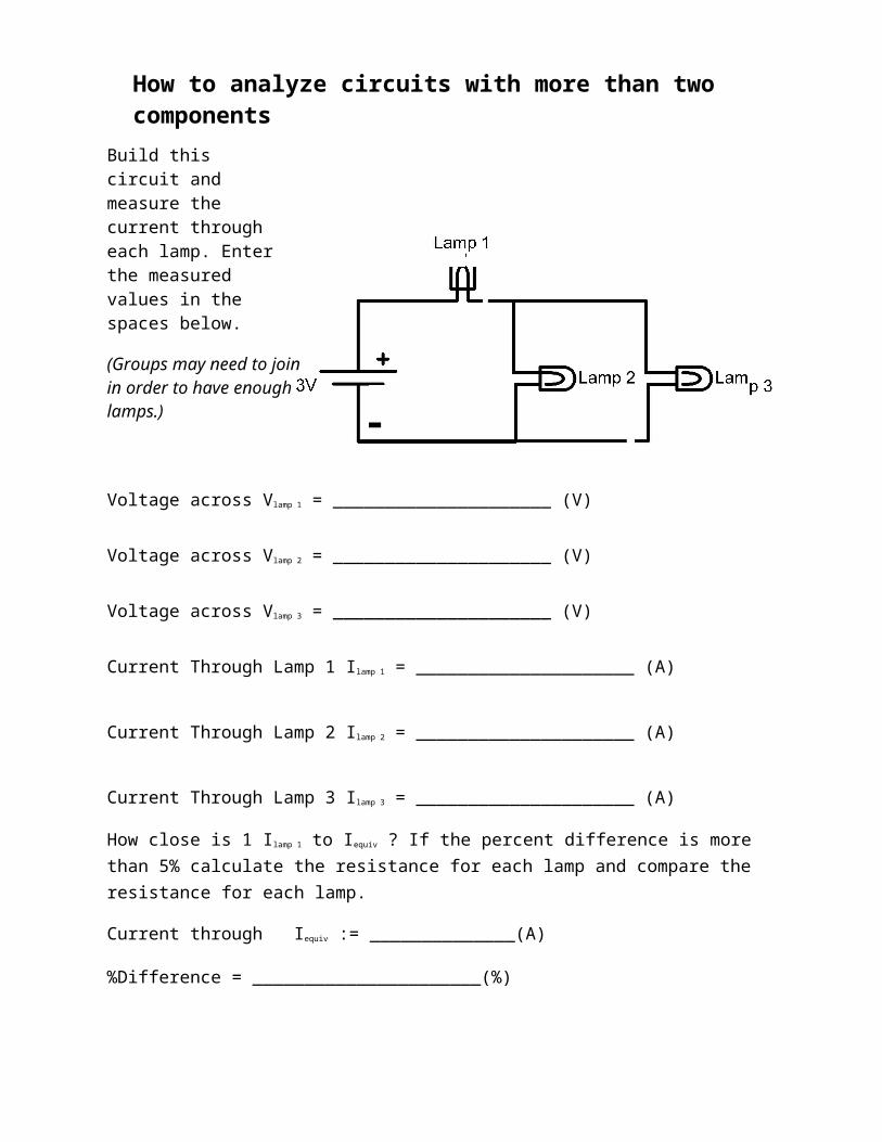
How to analyze circuits with more than two componentsBuild this circuit and measure the current through each lamp. Enter the measured values in the spaces below.
(Groups may need to joinin order to have enough
-lamps.)
Voltage across Vlamp 1 = _____________________ (V)
Voltage across Vlamp 2 = _____________________ (V)
Voltage across Vlamp 3 = _____________________ (V)
Current Through Lamp 1 Ilamp 1 = _____________________ (A)
Current Through Lamp 2 Ilamp 2 = _____________________ (A)
Current Through Lamp 3 Ilamp 3 = _____________________ (A)
How close is 1 Ilamp 1 to Iequiv ? If the percent difference is more than 5% calculate the resistance for each lamp and compare the resistance for each lamp.
Current through Iequiv := ______________(A)
%Difference = ______________________(%)
Does the current through lamp 1 equal the sum of the current through lamp 2 and lamp 3?

How to use the KVL

Using Kirchhoff’s voltage law circuit like the one to the right can be solve. Three loops must be taken (left, right, and bottom) these loops will yield 3 equations which are related. For consistence choose loops that are clockwise, the dot represents the starting position for each loop.
Note that the loops are thought of as current loops since voltage is the product of current and resistance. So the current through R2 is the difference of the currents I1 and I2, see the equations below forl ifi i
Note that loop 3 or L3: is a loop around the outer edge or the circuit.
Each equation need to be rearranged collecting the I’s together since they are the unknowns
Use the given resistances to the right for each lamp to eliminate all the R’s and use the measured voltage for the batteries in series to replace V1. Then solve by hand or using a calculator to find the currents I1, I2, I3, I4. Once done build the circuit, measure the current through each lamp and compare with the calculated values.
- I1
I2
I3
L1: R1I1R2(I1I2) V10 L2: R3I2R2(I2I1) 0L3: R4I3V1R1I1R3I2 0
Rearranged ↓
L1: (R1R2)I1R2I 2 V1 L2 : R2I1(R3 R2)I 2 0 L3: R1I1R3I 2 R4I3 V1
R1 = 9.14 ( Ω ) R3 = 3.61 (Ω)R2 = 3.61 ( Ω ) R4 = 7.2 (Ω)
Fill in the table below using the power measured in the series and parallel circuits
Calculated Measured % DifferenceI1
I2
I3

Use KVL to solve for the currents in this circuit

Similar to the previous page label the loops, get the system of equations and solve for the current.
The space below had be provided to write out the equations. Once the currents have been calculated build the circuit and measure the current entering all the information into the table below.
R1 = 7.06 ( Ω ) R3 = 6.86 ( Ω )
R2 = 7.33 ( Ω ) R4 = 6.82 ( Ω ) -

Fill in the table below using the power measured in the series and parallel circuits
Calculated Measured % DifferenceI1
I2
I3