Embed Size (px)
Citation preview

The Ring Laser Gyro Inertial Navigation SystemGraham Simms CEng, FIMechE
4th March 2019
Inertial navigation
Before the Second World War, pilots had to use a map and compass to work out where they were. It was a case of identifying features on the ground such as rivers, roads and railway lines, but this task became very difficult when flying over the oceans. Navigators aligned a sextant with the stars during night flying. During World War II, ground based radio transmitters, helped the navigator to plot the plane’s position and bearing.
An Inertial Navigation System (INS) requires no external sources and enables the pilot to navigate with an on-board system. It calculates an aircraft’s position, in its six degrees of freedom, by continuously detecting the motion of the aircraft and using that data to calculate the distance travelled and the angles turned. Besides providing the pilot with latitude, longitude and altitude, it also provides a Heading and Attitude Reference System (AHRS).
Accelerometers are used to measure the distance travelled. Accelerometers sense the force applied to a known mass during the acceleration or deceleration of the aircraft on which the INS is fitted.
Newton’s second law of motion states that: Force = Mass x Acceleration transposing this equation gives: Acceleration = Force / MassIntegrating Acceleration will give the Velocity of the aircraftIntegrating Velocity will give the Distance travelled
Three accelerometers are mounted in the three orthogonal axis. These are used to calculate the distance travelled in three directions: North-South, East-West and Up-Down. Thereby giving changes of Latitude, Longitude and Altitude.
But the accelerometers must stay in that attitude, pointing towards the North, East and Up. To do this, they are mounted on a gyroscopic platform. A spinning gyroscope mounted within gimbals will keep its axis pointing in the same direction, irrespective of any angular changes made by the aircraft. Contactless encoders detect the angles turned by the gimbals and these correspond to the angles turned by the aircraft.
The limitations of this arrangement are:1. Expensive precision mechanical parts are required2. Friction causes errors3. Regular maintenance is required4. Gimbal “locking” will occur if the gimbal axes are coincident during a
manoeuvre
A “strapdown” system is needed (i.e. no moving parts). This means that the accelerometers will be fixed with respect to the aircraft rotation and we will then need to measure the angular rotation rate.
Sagnac effect

Georges Sagnac was a French physicist who created an experiment in 1913 to prove that the speed of light is constant, irrespective of the speed of its source.
Figure 1. Stationary Figure 2. Rotating clockwise
A beam of light emitted from a coherent light source is split into two beams as it passes through a beam splitter. 50% of the light travels in a clockwise direction around a square path arrangement of mirrors, the remaining 50% of the light travels around the same path, but in a counter-clockwise direction. The two light beams then combine at the beam splitter and travel towards the detector.
While the equipment is stationary, the two beams will be in phase at the detector, but when the equipment is rotated clockwise, the beam of light travelling clockwise, has further to travel and the counter-clockwise travelling beam has less far to travel. This results with the two light beams being out-of-phase at the detector and an interference fringe pattern will occur. When the equipment is rotated counter-clockwise, the light travelling in the clockwise direction will now have less distance to travel and the interference pattern will reverse. (This is the operating principle for a Fibre Optic Gyro.)
Besides proving that the speed of light is a constant, this experiment is also a device to measure angular rotation. To see any effect, Sagnac had to rotate his equipment at 120 rpm and he needed a coherent light source. The experiment proved the principle, but using this device as a precision angular rate sensor had to wait until the invention of lasers.
Helium-Neon gas laser
A glass tube is filled with a mixture of 90% Helium and 10% Neon at a very low pressure (1 Torr, which is 1/1760 atmospheres).
Figure 3. Gas discharge tube
When a high voltage is applied to the electrodes, a gas discharge will be created. This is a light source that looks similar to the familiar Neon advertising signs.

Figure 4. The gas discharge reaction
The light is created when the flow of electrons within the discharge tube collide into the Helium atoms and thereby raising the energy level of those atoms. Each Helium atom quickly passes that energy to a Neon atom. The Neon atom then holds the energy for a short time before releasing it and this causes a photon to be emitted. The wavelength is often stated to be 632.8 nanometres, but for our purposes, we will say it is ‘approximately’ 632.8 nm, this will become apparent later.
As the Neon atom releases the photon spontaneously, this action is known as ‘spontaneous emission’. But a photon travelling through the gas can ‘trigger’ another Neon atom to release its photon before it does so spontaneously and this is known as ‘stimulated emission’. In this case, the two photons will then be travelling in the same direction, have the same wavelength and will be in-phase; they will be ‘coherent’. These two photons can then trigger more Neon atoms.
If the discharge tube is mounted between two parallel mirrors, any photons that are reflected back into the discharge tube will stimulate more Neon atoms to release their photons and the total light travelling in that direction will therefore be amplified. The acronym of this process is: LASER = Light Amplification by the Stimulated Emission of Radiation.
Figure 5. A Laser
For the lasing action to occur, the ‘gain’ must be greater than the ‘losses’. Most of the light is reflected back and forth in the optical cavity and only 1% is transmitted through the mirrors. The light discharged within the tube is the ‘gain’ and the mirrors are one of the ‘loss’ mechanisms. The photons that are amplified within the optical cavity will only be those that have a wavelength in which an integer number of them fit exactly between the mirrors. All other wavelengths will experience destructive interference. If the distance between the mirrors is increased or reduced, then photons that have a different wavelength will be amplified, i.e. those that now have an integer number that fit exactly. This is

possible because the photons within the gas discharge have a mean wavelength of 632.8nm and a small spread of slightly different wavelengths.
For lasing to occur, the mirrors must also be precisely parallel to each other. This is very unlikely if the mirrors are both flat. An analogy is to balance a pencil on its point, which is theoretically possible, but impossible in practice. However, if one of the mirrors is concave with a radius of curvature of say, 1 metre, a resonating path will always occur along a path that is a radial line of the curved mirror and at right angles to the flat mirror. However, this path must also pass through the length of the discharge tube.
Ring Laser Gyros
Instead of placing the discharge tube between two mirrors, let’s place it in an arrangement of three (or four) mirrors. Instead of travelling back and forth in a straight line the light beam now encloses an area. This is the basis of a ring laser gyro.
Figure 6. Ring laser gyro diagram
Although a resonating triangular path will always occur between three mirrors in the plan view, one of the mirrors will need to be curved, for the same reason as that for two mirrors, when considering the elevation view.
There is not a single laser beam, but there are two; one travelling around the triangular path in a clockwise direction (CW) and one travelling in the counter-clockwise direction (CCW). Because it is the same distance around the path for both beams, they will have the same wavelength, but that is only if the laser gyro is stationary. As demonstrated with the Sagnac effect, when the laser gyro is rotated, the beam that is travelling in the same direction as the rotation will have further to travel and the other beam will have less far. But unlike the Sagnac effect, in which a ‘phase’ change creates a fringe pattern, this resonating cavity will cause each laser beam to change its wavelength to fit the apparent path of the rotating cavity.
A prism, with a 50% beam splitter is attached to one of the mirrors to enable the CW and CCW to be superimposed and measured using a photo-diode. With no rotation, the CW and CCW beams have the same wavelength and the superimposed beams will be additive. However, when the laser gyro is rotated, the CW and CCW will have different wavelengths and the light intensity at the

photo-diode will ‘beat’ (a pulsing of the light intensity), this enables an electronic circuit to count the beats. A laser gyro having a path length of 30 cm will produce approximately 300,000 beats per revolution – and that is independent of the ‘rate’ of rotation. If the laser gyro is rotated faster, this will produce faster beats, but there will still be the same number of beats per revolution.
One, or two, of the mirrors are designed to flex and are activated using a piezoelectric element. This enables the path length to be controlled such that the laser beam is resonating at maximum intensity. This adjustment affects both the clockwise and counter-clockwise beams equally and has no effect on the output pulses when the ring laser is being rotated.
Figure 7. Lock-in
Laser gyros suffer from ‘lock-in’; there is no output pulses at very low rotation rates. Even though the laser gyro is rotating slowly, the wavelength of the CW and CCW beams ‘lock’ together and have the same wavelength. This happens because some of the photons of the CW beam scatter backwards and join the CCW beam, and vice-versa. This cross-talk or ‘lock-in’ effect is also a familiar problem for those building electronic circuits when it is known as a ‘coupled oscillator’. There is also a mechanical analogy; imagine two pendulum clocks, of which one is running slightly fast and the other is running slightly slow, if these were attached next to each other on the same wall, there could be a transfer of energy between the clocks causing the pendulums to swing together.
A small amount of the ‘back scatter’ of light occurs at the mirrors, but much more back-scatter occurs as the light passes through the windows at the ends of the discharge tube. This back-scatter will be greatly reduced if the laser gyro is designed in which there are no windows within the optical cavity.
The ‘Monobloc’ arrangement achieves this and provides extra benefits such as increasing the ‘gain’ length of the gas discharge tube and also resulting with a more rigid design for this device. However, the Monobloc design introduces new problems to be overcome i.e. as the mirrors will now seal the gas within the cavity, their position can therefore not be adjusted.
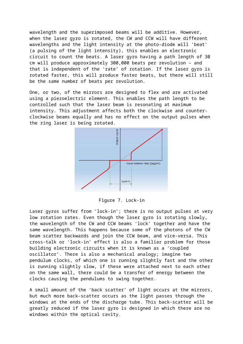
Figure 8. A 30 cm Ring Laser Gyro Monobloc
To keep the RLG stable during any changes to temperature, the Monobloc is made from an Ultra-Low Expansion (ULE) glass ceramic. An ultrasonic drill with diamond tipped drills produce the holes for the laser beam, the discharge paths and holes to provide extra ballast volume for the gas. The external faces, on which the mirrors are mounted, are ground and polished to a flatness of 1/10 of the wavelength of light, the angles between the faces are within 5 arc seconds in both planes, the positions of these faces must coincide with the intersection of the centres of the drilled holes and the faces must be free of scratches.
The electrode faces, and the areas on the Monobloc where the electrodes are to be attached, are coated in gold and an Indium ‘O-ring’ is compressed between each electrode and the Monobloc face to produce a hermetic seal. The mirrors are not attached using glue or an ‘O-ring’; as the mirror surface and the Monobloc faces are made to such high precision, the mirrors ‘bond’ to the Monobloc on contact, producing a permanent hermetic bond. This is known as optical ringing.
Although the ‘lock-in’ effect is dramatically reduced with the Monobloc design, it is not totally eliminated. An additional solution to overcome this problem is the dither mechanism.
The dither mechanism applies a small oscillating rotation to the Monobloc about its rotation axis to keep the laser gyro above the ‘lock-in’ threshold for most of the time. This is achieved with a mechanical spring that is shaped like the spokes of a wheel. A piezoelectric element is bonded to each spoke to provide a small angular movement to the Monobloc. When the applied oscillation matches the natural resonant frequency of the whole assembly, the motion is amplified.
The laser gyro senses this applied rotation and produces a stream of pulses corresponding to the CW and CCW rotations. When the laser gyro is stationary and dithering, the CW and CCW pulses are equal. So adding the CW and CCW pulses together will give the net rotation of the laser gyro about its axis.
When the laser gyro axis is vertical and the device is fixed with respect to the ground, it produces an output corresponding to the rotation rate of the earth; the earth is rotating at 15 degrees/hour, the rate sensed about its vertical axis will depend on the latitude position of the device and will be zero at the equator.

Figure 9. An assembled laser gyroThis 70cm RLG assembly is on display in the FAST museum
(Farnborough Air Sciences Trust)
Three laser gyros and three accelerometers are mounted on three orthogonal axis to produce an Inertial Measuring Unit (IMU). The combination of these can be used to sense the rotation of the earth and the direction of gravity. This information allows the Inertial Navigation System (INS) to determine the direction for true North and the direction of the vertical axis to be calculated, anywhere on the earth. After switching the system on, the pilot will need to wait a few minutes for the INS to determine these directions before moving the aircraft. The current Latitude and Longitudinal positions of the aircraft is entered manually into the system. From then onwards, as the aircraft taxis and during the flight, the INS will continuously provide the current Latitude, Longitude, Altitude, Heading, Pitch and Attitude to the flight control system.
Three axis laser gyro
As three laser gyros are used in the INS, it is appealing to design a device that has the three laser gyros integrated into a single Monobloc. A convenient solution to this is to consider three laser gyros that each have a square laser path in a cube of a ULE Monobloc as shown in figure 10.

Figure 10. Three axis laser gyro(The photograph is taken from ‘Flight International’ magazine March 9th 1985)
This arrangement is known as the ‘Triad’ and besides occupying less space, it has a greater rigidity and robustness and requires fewer mirrors. The mirrors are an expensive component and the Triad requires only 6 mirrors instead of 9 for the three axes.
Only one dither spring is required. This is mounted to the face opposite the cathode and simultaneously produces an oscillating angular rate to each axis.
Applications for the Ring Laser Gyro INS include:
Commercial aircraft (Three systems are installed in each aircraft)
Military aircraft (A demanding environmental specification)
Ships (Larger RLGs are used to increase the sensitivity)
Submarines (GPS signals cannot be received under water)
Missiles (Small space, but short flight time)
Drilling rigs (The drill head is guided to produce an array of holes)
Figure 11. Oil or gas drilling rig