Embed Size (px)
Citation preview
UNIT IV HARMONICS (9)Harmonic distortion – Voltage and current distortion – Harmonic indices – Harmonic sources from commercial and industrial loads – Locating harmonic sources – Power system response characteristics – Resonance – Harmonic distortion evaluation – Devices for controlling harmonic distortion – Passive filters – Active filters – IEEE and IEC standards
Part A
1. Define harmonic.A harmonic is a component of a periodic wave having a frequency that is an integral multiple of
the fundamental power line frequency of 50 Hz. Total harmonic distortion is the contribution of all the harmonic frequency currents to the fundamental.2. What is harmonic number?
Harmonic number (h) refers to the individual frequency elements that comprise a composite waveform. For example, h= 5 refers to the fifth harmonic component with a frequency equal to five times the fundamental frequency.3. What is meant by distortion factor?
The distortion factor is defined as
where, n=2,3,4…. an – the magnitude of the harmonic frequencies a1 - the magnitude of the fundamental component
4. What are the sources of harmonics?Among the sources of harmonic voltages and currents in power systems three groups of equipment can be distinguished: Magnetic core equipment, like transformers, electric motors, generators, etc. Arc furnaces, arc welders, high-pressure discharge lamps, etc. Electronic and power electronic equipment.
5. Define THD.Total Harmonic Distortion is defined as the ratio of the root mean square value of the harmonic content to root mean square value of the fundamental quantity, expressed as percent of the fundamental. It is measure of effective value of harmonic distortion.
6. What is passive filter?These are LC resonating or parallel resonating circuits which offer very high or low impedance at tuning frequency. These filters are resistive at tuned frequency, capacitive at below tuned frequencies and inductive beyond tuned frequency.
7. What is the significance of power quality indices?In practice, the PQ indices represent, for compactness and practicality, the quickest and most useful way to describe the characteristics of PQ disturbances. They are convenient for condensing complex time and frequency domain waveform phenomena into a single number.
8. What are the power quality indices?Waveform distortions (voltage or current) can be characterized by several indices and the most frequently used are:

the individual harmonic; the total harmonic distortion factor; the individual interharmonic; the total interharmonic distortion factor.
9. Define TDD.Total Demand Distortion is defined as the ratio of the root mean square value of the harmonic content to root mean square value of the demand current, expressed as percent of the demand current. It is measure of effective value of harmonic distortion.
where IL - rms value of maximum demand load currenth - harmonic order (1, 2, 3, 4, etc.)Ih - rms load current at the harmonic order h
10. What are the harmonic elimination techniques? Series connected filters Shunt connected filters Passive filters
11. What are the advantages of passive filters?i. Simple in construction, less costly and efficient
ii. Serves dual purpose harmonic filtration and power factor correction of load.12. What are the disadvantages of passive filters?
i. Cannot function under saturated condition.ii. Number of passive filters installed must be equal to the number of harmonic levels to be
compensated.iii. Connection of passive filters necessities a specific analysis of each installation.iv. Non adaptability to system variations .v. Bulky in size.
vi. Tendency to resonate with the other load.13. What is voltage and current distortion?Harmonic voltages result from the harmonic currents interacting with the impedance of the power system according to Ohm’s law:
where, V - voltageI - currentZ - impedance
Harmonic currents and voltages have a detrimental effect on utility and end-user equipment. They cause overheating of transformers, power cables, and motors; inadvertent tripping of relays; and incorrect measurement of voltage and current by meters.
14. Differentiate linear and nonlinear loads.
Linear Loads: AC electrical loads where the voltage and current waveforms are sinusoidal. The current at any time is proportional to voltage. Linear Loads are:

Power Factor Improvement Capacitors, Incandescent Lamps, Heaters etc.,
Nonlinear Loads: Nonlinear loads are simply any piece of equipment or appliance that increases and reduces its consumption of electricity over time in a nonlinear fashion. With nonlinear loads the current and voltage do not follow each other linearly. Nonlinear loads are: Computer, laser printers, SMPS, rectifier, PLC, electronic ballast, refrigerator, TV etc.
15. What is the effect of harmonics on transformer?The effects of harmonics on transformers manifest in two ways:
Eddy current losses, which can be estimated to be normally around 10% of the losses at full load, increase with the square of the harmonic order. For example, for a fully loaded transformer supplying a load comprising IT equipment, the total losses would be twice as high as for an equivalent linear load. These additional losses may result in a much higher operating temperature and a shorter life, therefore this effect must be taken into account at design stage.
Triplen harmonic currents, when reflected back to a delta winding, are all in phase so they can circulate in the winding. These components are absorbed in the windings and do not propagate onto the supply; for this reason delta-wound transformers are useful as isolating transformers. Of course this circulating current has to be taken into account when rating the transformer.
16. What is IEC standard? Give at least two IEC standards for EMC.The International Electrotechnical Commission (IEC), currently with headquarters in
Geneva, Switzerland, has defined a category of electromagnetic compatibility (EMC) standards that deal with power quality issues. They are,
IEC 61000-2-2 (1993) IEC 61000-3-2 (2000) IEC 61000-3-4 (1998) IEC 61000-3-6 (1996)
17. Mention the devices to control harmonic distortion.Three different solutions can be adopted in the reduction of the harmonic distortion:
i. Reduction of harmonic emission from non-linear loads, by modifications to their structure;
ii. High harmonic filters (passive and active); and iii. Isolation and harmonic reduction transformers.
The devices used to control harmonic distortion are,i. Reinforce distribution system
ii. Passive Filtersiii. Active Filtersiv. Isolation transformersv. Harmonic mitigation transformer
vi. Multi-pulse converters18. What are the advantages of active filters?
Superior filtering performance Smaller physical size Flexibility

Part B1. Explain the harmonic phase rotation and phase angle relationship. (08)
Power engineers have traditionally used symmetrical components to help describe three-phase system behavior. The three-phase system is transformed into three single-phase systems that are much simpler to analyze. The method of symmetrical components can be employed for analysis of the system’s response to harmonic currents provided care is taken not to violate the fundamental assumptions of the method.
The method allows any unbalanced set of phase currents (or voltages) to be transformed into three balanced sets. The positive-sequence set contains three sinusoids displaced 120° from each other, with the normal A-B-C phase rotation (e.g., 0°, -120°, 120°). The sinusoids of the negative-sequence set are also displaced 120°, but have opposite phase rotation (A-C-B, e.g., 0°, 120°, -120°). The sinusoids of the zero sequence are in phase with each other (e.g., 0°, 0°, 0°).
In a perfect balanced three-phase system, the harmonic phase sequence can be determined by multiplying the harmonic number h with the normal positive-sequence phase rotation. For example, for the second harmonic, h=2, we get 2X(0, -120°, -120°) or (0°, 120°, -120°), which is the negative sequence. For the third harmonic, h = 3, we get 3X (0°, -120°, -120°) or (0°, 0°, 0°), which is the zero sequence. Phase sequences for all other harmonic orders can be determined in the same fashion.Since a distorted waveform in power systems contains only odd-harmonic components, only odd-harmonic phase sequence rotations are summarized here:
Harmonics of order h = 1, 7, 13,… are generally positive sequence. Harmonics of order h = 5, 11, 17,… are generally negative sequence. Triplens (h = 3, 9, 15,…) are generally zero sequence.
2. Explain the process of locating harmonic sources. (08)
On radial utility distribution feeders and industrial plant power systems, the main tendency is for the harmonic currents to flow from the harmonic-producing load to the power system source. This is illustrated in Fig.4.1. The impedance of the power system is normally the lowest impedance seen by the harmonic currents. Thus, the bulk of the current flows into the source.
Fig.4.1. General flow of harmonic current in radial systemThis general tendency of harmonic current flows can be used to locate sources of harmonics.
Using a power quality monitor capable of reporting the harmonic content of the current, simply measure the harmonic currents in each branch starting at the beginning of the circuit and trace the harmonics to the source.
Power factor correction capacitors can alter this flow pattern for at least one of the harmonics. For example, adding a capacitor to the previous circuit as shown in Fig. 5.24 may draw a large amount of harmonic current into that portion of the circuit. In such a situation, following the path of the harmonic current will lead to a capacitor bank instead of the actual harmonic source. Thus, it is generally necessary to temporarily disconnect all capacitors to reliably locate the sources of harmonics.

It is usually straightforward to differentiate harmonic currents due to actual sources from harmonic currents that are strictly due to resonance involving a capacitor bank. A resonance current typically has only one dominant harmonic riding on top of the fundamental sine wave. Note that none of the harmonic sources presented earlier in this chapter produce a single harmonic frequency in addition to the fundamental. They all produce more than one single harmonic frequency. Waveforms of these harmonic sources have somewhat arbitrary waveshapes depending on the distorting phenomena, but they contain several harmonics in significant quantities. A single, large, significant harmonic nearly always signifies resonance.
Fig.4.2. Power factor capacitors can alter the direction of flow of one of the harmonic components of the current.
This fact can be exploited to determine if harmonic resonance problem are likely to exist in a system with capacitors. Simply measure the current in the capacitors. If it contains a very large amount of one harmonic other than the fundamental, it is likely that the capacitor is participating in a resonant circuit within the power system. Always check the capacitor currents first in any installations where harmonic problems are suspected.
3. What are the harmonic sources from commercial and industrial loads. (06)
Harmonics of different orders generated when connected power system network by different sources as below:
i. The non linear loads such as inverter fed adjustable speed drive.ii. The use of powerfactor correction capacitor creates parallel or series resonance problems
increasing the harmonic distortion.iii. Process control and solid state power conversion equipments.iv. Energy efficient compact flourescent lamps. v. Use of AC and DC adjustable speed drives
vi. Static VAR compensators.vii. Transformers produce very high levels of harmonics when they are initially energized,
the so called in rush current will generate harmonics of several orders.viii. Cycloconverters,Lift control system,Traction,AC voltage regulators, UPS, Battery
chargers.
4. What are the effects of harmonics (06).
The duration presence of long duration harmonic cause more serious effects on the various equipments connected to the power system.
Amplitude of harmonics: Large amplitude harmonics of short duration under resonance condition cause dielectric breakdown due to over voltages. Now a day various devices and equipment being measured applications are more sensitive compared to the past.

The capacitor used for power factor correction and in different filters decreases resulting in increasing in current drawn by capacitor beyond permissible limits. The capacitor acts as sink for harmonic currents resultant effect of harmonics is overloading , hence over heating increases dielectric stress and increase the power lost. The thermal failure of capacitor may take place because of higher temperature.
Non sinusoidal power supplies results in reduction of torque of induction motor.
It will increase interference with telephone, communication and logic circuits.
Error in reading of induction type energy meters which are calibrated for pure sinusoidal A.C power.
Higher order harmonics causes voltage stress and corona.
Presence of harmonics in power system network can cause additional losses in power system network, overheating of transmission lines, transformers and generators etc.
Malfunction or even failure of electronic or computer controls.
Hence it is clear that day by day the increase in harmonic contents will impose new problems on operations of electronic equipment. The energy efficient electronic equipment that will be produced in future trends result in poor performance due to the voltage distortion. Hence it is essential to have the proper coordination between the supply authorities and consumers regarding the power quality problem, their causes and results and solutions available to eliminate them.
5. Explain active and passive filters in harmonic control. (10)
Passive Filters:
They include devices that provide low impedance paths to divert harmonics to ground and devices that create a high impedance path to discourage the flow of harmonics. Both of these devices, by necessity, change the impedance characteristics of the circuits into which they are inserted. Another weakness of the passive harmonic technologies is that they cannot adapt to changes in electrical systems in which they operate. This means that changes to electrical system could cause them to be overloaded or to create resonances that could actually amplify, rather than diminish harmonics.
Fig.4.3. Passive Filters
Advantages of Passive filters:

1. Simple in construction, less costly and efficient
2. Serves dual purpose harmonic filtration and power factor correction of load.
Disadvantages of Passive filters:
1. Cannot function under saturated condition.
2. Number of passive filters installed must be equal to the number of harmonic levels to be compensated.
3. Connection of passive filters necessities a specific analysis of each installation.
4. Non adaptability to system variations.
5. Bulky in size.
6. Tendency to resonate with the other load.
Active filters:
When the number of harmonics to be filtered, large no of branches of passive filters will be required . The large no of branches of passive filters will be required. The actual number of branches will depend upon no of harmonic level of branches will depend upon no of harmonic level to be compensated. Hence, because of passive filter use for filtration of large no of harmonics results in large size &more cost. Introduction of self commutated devices e.g. MOSFETS, IGBT etc, accelerated the research in design of active filter & resulted low cost, high performance active filter suitable to eliminate the harmonics of different orders to overcome the drawbacks of passive filters.
Active filters compensate voltage of current harmonic signal measured. The injected voltage or current harmonic signal measured. The injected voltage or current harmonic signals in to the power system network is of same magnitude and opposite in phase of the measured harmonic signal. It comprises power converter and control loop which controls the harmonics injection of the filter as the function of harmonic signal measure.
Advantages of Active filters:
Superior filtering performance
Smaller physical size
Flexibility
6. Write notes on harmonic indices. (8)
Total Harmonic Distortion:
Current distortion levels can be characterized by a THD value, as has been described, but this can often be misleading. A small current may have a high THD but not be a significant threat to the system. For example, many adjustable-speed drives will exhibit high THD values for the input current when they are operating at very light loads. This is not necessarily a significant concern because the magnitude of harmonic current is low, even though its relative current distortion is high.

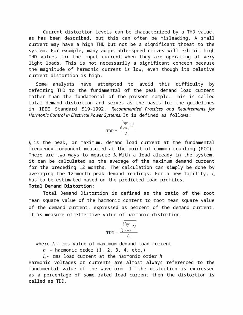
Some analysts have attempted to avoid this difficulty by referring THD to the fundamental of the peak demand load current rather than the fundamental of the present sample. This is called total demand distortion and serves as the basis for the guidelines in IEEE Standard 519-1992, Recommended Practices and Requirements for Harmonic Control in Electrical Power Systems. It is defined as follows:
IL is the peak, or maximum, demand load current at the fundamental frequency component measured at the point of common coupling (PCC). There are two ways to measure IL. With a load already in the system, it can be calculated as the average of the maximum demand current for the preceding 12 months. The calculation can simply be done by averaging the 12-month peak demand readings. For a new facility, IL has to be estimated based on the predicted load profiles.Total Demand Distortion:
Total Demand Distortion is defined as the ratio of the root mean square value of the harmonic content to root mean square value of the demand current, expressed as percent of the demand current. It is measure of effective value of harmonic distortion.
where IL - rms value of maximum demand load currenth - harmonic order (1, 2, 3, 4, etc.)Ih - rms load current at the harmonic order h
Harmonic voltages or currents are almost always referenced to the fundamental value of the waveform. If the distortion is expressed as a percentage of some rated load current then the distortion is called as TDD.7. What are the importances of measuring harmonics and mention the instruments used for the
measurement? (8)
Importance of Hormonic measurement: Measurement provides the real time information about the power system network to utilities,
consumer and designer .Filters designed after harmonic measurements are technically better and economical.
Measurement provides information to analyze the combined effect of harmonic generated by different loads on power quality.
Different types of instruments available for harmonic measurement are : Power profiler: It can measure and print in addition to various electric quantities voltage and
current total harmonic distortion and frequency. Power network analyzer: It is portable three phase network analyzer designed for power
surveys in which the measured data are transformed to PC for evaluation and documentation. Measurement setup: The measurement is done via high quality probe. The computer loads the
waveforms of graph sheets. Memory hicorder: It is used to measure three line currents and there line to voltage.

Dynamic signal analyzer model: The parameters such as fundamental frequency of A.C. current, line or phase voltage across potential transformer.
8. Write notes on standards for waveform distortions. (10)
Standards prescriptions define the limits on voltage supply, measurement method and instruments, mitigation process, etc. The main IEC standards dealing with harmonics and interharmonics are presented. Essential standards regarding the harmonics are EN 50160, IEEE 519-1992 and IEEE 1159-1995.
‘Bureau of Indian Standards’ specified that the voltage is considered to be virtually sinusoidal, if, when supplying an AC motor at rated voltage, the waveform is such that the difference between the instantaneous value of the fundamental component does not exceed 5% of the amplitude.
Currently defined distortion limits assume that there will be some diversity between the harmonic currents injected by different customers. This diversity can be in the form of different harmonic components being injected, differences in the phase angles of the individual harmonic currents, or differences in the harmonic injection versus time profiles. In recognition of this diversity, the current limits are developed so that the maximum individual frequency harmonic voltage caused by a single customer will not exceed the limits in tables for systems that can be characterized by a short-circuit impedance.
IEEE Standards for voltage harmonics:
IEEE standards for voltage harmonics distortions followed internationally are given in the following table.
Bus Voltage at PCC Individual Voltage distortion (%) THD (%)
69kV and Below 3.0 5.0
69 to 161 kV 1.5 2.5
161 and above 1.0 1.5
IEEE Standards for Current Harmonics:
IEEE Standards followed internationally for general distribution system for end user limits (120V to 69kV) is given in the following table.
9. Discuss about the harmonic sources of commercial and industrial loads. (16)
Harmonic Sources – Commercial Loads:
Commercial Places:
Office complexes
Department stores
Hospitals and
Internet data centers
Loads:
High-efficiency fluorescent lighting with electronic ballasts
Adjustable-speed drives for the heating, ventilation, and air conditioning (HVAC) loads
Elevator drives and
Sensitive electronic equipment supplied by single-phase switch-mode power supplies.
o Commercial loads are characterized by a large number of small harmonic-producing loads. Depending on the diversity of the different load types, these small harmonic currents may add in phase or cancel each other.
o Voltage distortion levels depend on both the circuit impedances and the overall harmonic current distortion.
Single-phase power supplies:
Electronic power supplies are very important in commercial premises because of increased utilization of personal computers, adjustable speed drives, dc motor drives, battery charges etc.,
The SMPS is now replacing the old transformer power supplies. The input diode bridge is directly connected to the AC main, eliminating transformer. The direct current is then converted back to AC at very high frequency by the switches and subsequently rectified again. All
computer peripherals are now employ SMPS because of its light weight, compact size, efficient operation and lack of need for a transformer.
SMPS causes very high 3rd Harmonics. These 3rd Harmonics causes overloading of neutral conductors, especially where undersized old neutral wires may have been installed.
Fig.4.4. Current and Frequency spectrum of SMPS
Fluorescent Lighting:
Commercial building loads consumes 40% - 60% of generated energy for lighting
Lighting (1995) – 77% Fluorescent lighting, 14% Incandescent lighting.
In discharge lamps, ballasts are used for generating high initial voltage. After establishing the electron flow from one electrode to another, arc current increases and the voltage decreses.
Discharge is a short circuit. Ballast has to reduce the current within the limit to maintain the specified lumen output. i.e, Ballast is also a current limiting device.
Types: 1. Magnetic Ballast and 2. Electronic Ballast.
Magnetic Ballast: It is made with iron core and used with a capacitor. It produces heat loss.
Electronic Ballast: Switch mode power supply is used to convert the fundamental frequency voltage in to a much higher frequency (25-40 kHz) voltage.
Advantages of High frequency:
Small inductor is enough to limit the arc current.
High Frequency eliminates 100 or 120 Hz flicker associated with iron core magnetic ballast.
Magnetic Ballast can be used for 2 lamps. But electronic Ballast can be used for 4 lamps.
Comparison: Electronic Ballast produces double or triple the standard magnetic ballast harmonic output.
Other electronic ballasts have been specifically designed to minimize harmonics and may actually produce less harmonic distortion than the normal magnetic ballast-lamp combination.

Typical THD allowed in electronic ballast is betwee10-32%.
THD greater than 32% is excessive according to ANSI C82.11-1993, High frequency Fluorescent Lamp Ballasts.
In many cases, passive filtering used to reduce input current harmonic distortion to less than 20%.
Harmonics in commercial buildings are usually distributed along the phases in a nearly balanced manner.
Fig.4.5. Current and Frequency spectrum of fluorescent lighting
Adjustable Speed Drives:
Applications of ASDs:
o Elevator Motors
o Pumps and Fans of HVAC Systems
ASD consists of electronic power converter that converts constant ac voltage and frequency into variable voltage and frequency.
Variable voltage and frequency allows the ASD to control motor speed to match the application requirement such as slowing a pump or fan.
ASDs also find many applications in industrial loads
Harmonic Sources – Industrial Loads:

In modern Industries, non linear loads are unavoidable today. They are injecting harmonics in to the system.
Non linear Loads are operating at low power factor. Therefore, power factor correction strategies are applied to the system. Widely using power factor correction capacitors magnify the harmonics.
High Voltage distortions are experienced at LV side (Capacitor side).
At resonance condition, motor and transformer overheating, and misoperation of sensitive electronic equipment are occurred.
Three categories of nonlinear industrial loads :
Three-phase power converters
Arcing devices and
Saturable devices.
Three-phase power converters:
All equipment containing static converters, as variable speed controllers, UPS units and a.c./d.c. converters in general, are based on a three-phase bridge, also known as a six-pulse bridge because there are six voltage pulses per cycle (one per half cycle per phase) on the d.c. output.
This bridge produces in supply networks current harmonics of order 6n±1, which means one more and one less than each multiple of six. In theory, the magnitude of each harmonic should be equal to the reciprocal of the harmonic number, so there would be 20% of the 5th harmonic and 9% of the 11th harmonic, etc. Figure 7.19 shows an example waveform of a thyristor bridge current against the phase voltage. Commutation notches are clearly visible in the voltage waveform (the source of high-frequency distorting components).
The magnitude of the harmonics is significantly reduced by the use of a 12-pulse converter.
Fig.4.6 Example waveforms of the supply voltage and current of a six-pulse thyristor bridge with d.c. side reactor

Arcing Devices:
The following are the arcing devices:
Arc furnaces,
Arc welders, and discharge-type
Lighting (fluorescent, sodium vapor, mercury vapor) with magnetic ballasts.
The voltage-current characteristics of electric arcs are nonlinear. Following arc ignition, the voltage decreases as the arc current increases, limited only by the impedance of the power system.
In electric arc furnace applications, the limiting impedance is primarily the furnace cable and leads with some contribution from the power system and furnace transformer. Currents in excess of 60,000 A are common.
The electric arc itself is actually best represented as a source of voltage harmonics. Its magnitude is largely a function of the length of the arc. The arcing load thus appears to be a relatively stable harmonic current source, which is adequate for most analyses. The exception occurs when the system is near resonance and a Thevenin equivalent model using the arc voltage waveform gives more realistic answers.
Three phase arcing devices can be arranged to cancel the triplen harmonics through the transformer connection. However, this cancellation may not work in three-phase arc furnaces because of the frequent unbalanced operation during the melting phase. During the refining stage when the arc is more constant, the cancellation is better.
Saturable Devices:
Equipment in this category includes transformers and other electromagnetic devices with a steel core, including motors. Harmonics are generated due to the nonlinear magnetizing characteristics of the steel.
Power transformers are designed to operate below the ‘knee point’ of the magnetic saturation characteristics. Selection of the operating point depends on,
Steel cost
No-load losses
Noise and
Other factors
Some transformers are purposefully operated in the saturated region. One example is a triplen transformer used to generate 180 Hz for induction furnaces.

Motors also exhibit some distortion in the current when overexcited, although it is generally of little consequence. There are, however, some fractional horsepower, single-phase motors that have a nearly triangular waveform with significant third-harmonic currents.
Fig.4.7. Transformer magnetizing current and harmonic spectrum.The waveform shown in Fig. 5.22 is for single-phase or wye-grounded three-phase
transformers. The current obviously contains a large amount of third harmonic. Delta connections and ungrounded-wye connections prevent the flow of zero-sequence harmonic, which triplens tend to be. Thus, the line current will be void of these harmonics unless there is an imbalance in the system.
_________________________