Embed Size (px)
Citation preview
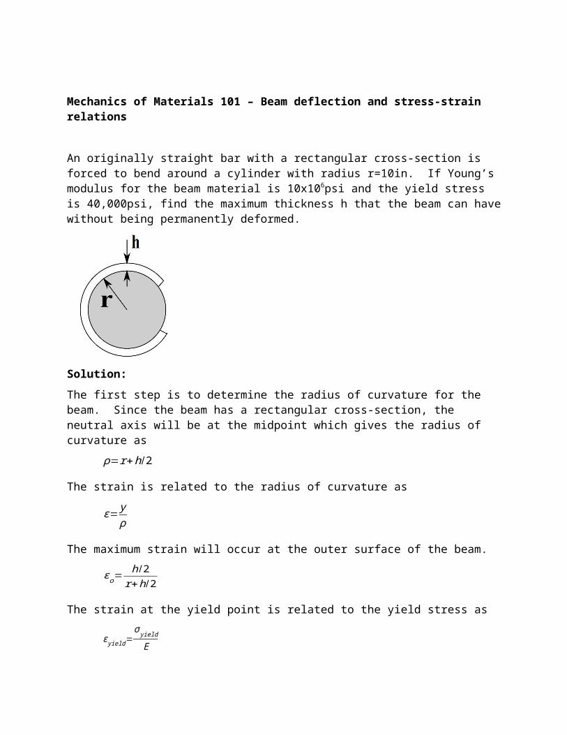
Mechanics of Materials 101 – Beam deflection and stress-strain relations
An originally straight bar with a rectangular cross-section is forced to bend around a cylinder with radius r=10in. If Young’s modulus for the beam material is 10x106psi and the yield stress is 40,000psi, find the maximum thickness h that the beam can have without being permanently deformed.
Solution:
The first step is to determine the radius of curvature for the beam. Since the beam has a rectangular cross-section, the neutral axis will be at the midpoint which gives the radius of curvature as
ρ=r+h/2
The strain is related to the radius of curvature as
ε= yρ
The maximum strain will occur at the outer surface of the beam.
ε o=h/2
r+h/2
The strain at the yield point is related to the yield stress as
ε yield=σ yield
E
We will equate the maximum strain to the yield strain.
h/2r+h/2
=σ yield
E
Solving for h gives
h=2σ yield rE−σ yield
=2( 40 ,000 psi)(10 in )
10 x106 psi−40 ,000 psi=0 . 08 in
Author: Kennedy, T.C.Subject: Mechanics of MaterialsTopic: Combining beam deflection and stress-strain relationsProblem Length: 10 minutesGrading: Hand gradedPresentation Format: Text and figure with problem statementOther:
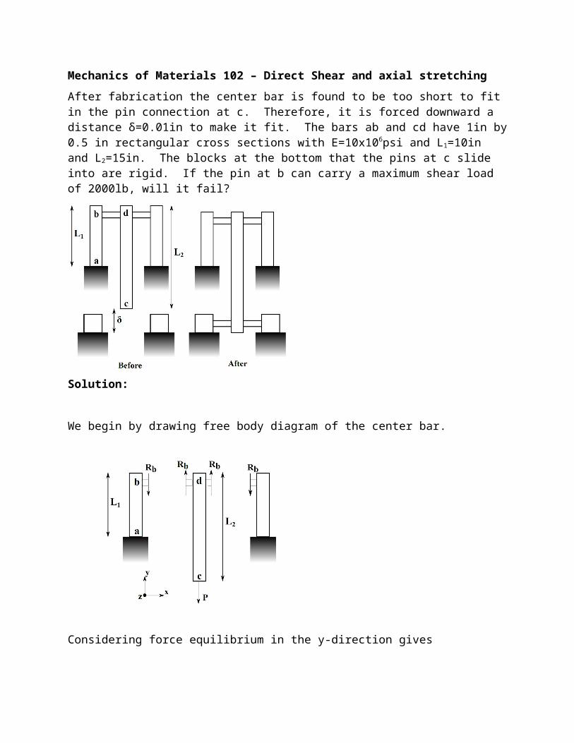
Mechanics of Materials 102 – Direct Shear and axial stretching
After fabrication the center bar is found to be too short to fit in the pin connection at c. Therefore, it is forced downward a distance δ=0.01in to make it fit. The bars ab and cd have 1in by 0.5 in rectangular cross sections with E=10x106psi and L1=10in and L2=15in. The blocks at the bottom that the pins at c slide into are rigid. If the pin at b can carry a maximum shear load of 2000lb, will it fail?
Solution:
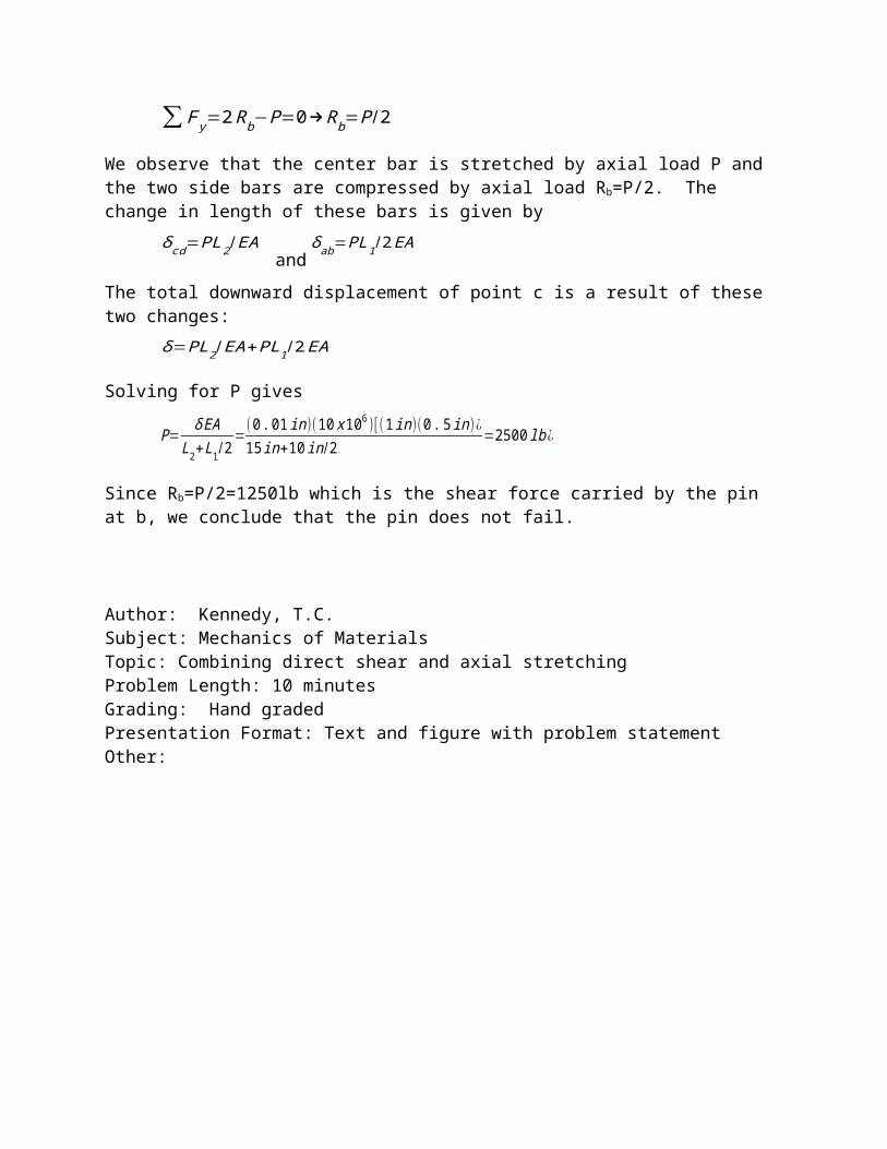
We begin by drawing free body diagram of the center bar.
Considering force equilibrium in the y-direction gives
∑ F y=2 Rb−P=0→Rb=P/2
We observe that the center bar is stretched by axial load P and the two side bars are compressed by axial load Rb=P/2. The change in length of these bars is given by
δ cd=PL2 / EA and
δ ab=PL1 /2 EA
The total downward displacement of point c is a result of these two changes:
δ=PL2 / EA+PL1/2 EA
Solving for P gives
P= δ EAL2+L1 /2
=(0. 01 in )(10 x 106 )[ (1in )(0 . 5 in )¿15 in+10 in/2
=2500 lb ¿
Since Rb=P/2=1250lb which is the shear force carried by the pin at b, we conclude that the pin does not fail.
Author: Kennedy, T.C.Subject: Mechanics of MaterialsTopic: Combining direct shear and axial stretchingProblem Length: 10 minutesGrading: Hand gradedPresentation Format: Text and figure with problem statementOther:
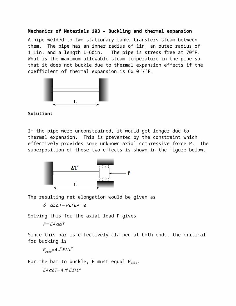
Mechanics of Materials 103 – Buckling and thermal expansion
A pipe welded to two stationary tanks transfers steam between them. The pipe has an inner radius of 1in, an outer radius of 1.1in, and a length L=60in. The pipe is stress free at 70°F. What is the maximum allowable steam temperature in the pipe so that it does not buckle due to thermal expansion effects if the coefficient of thermal expansion is 6x10⁻⁶/°F.
Solution:
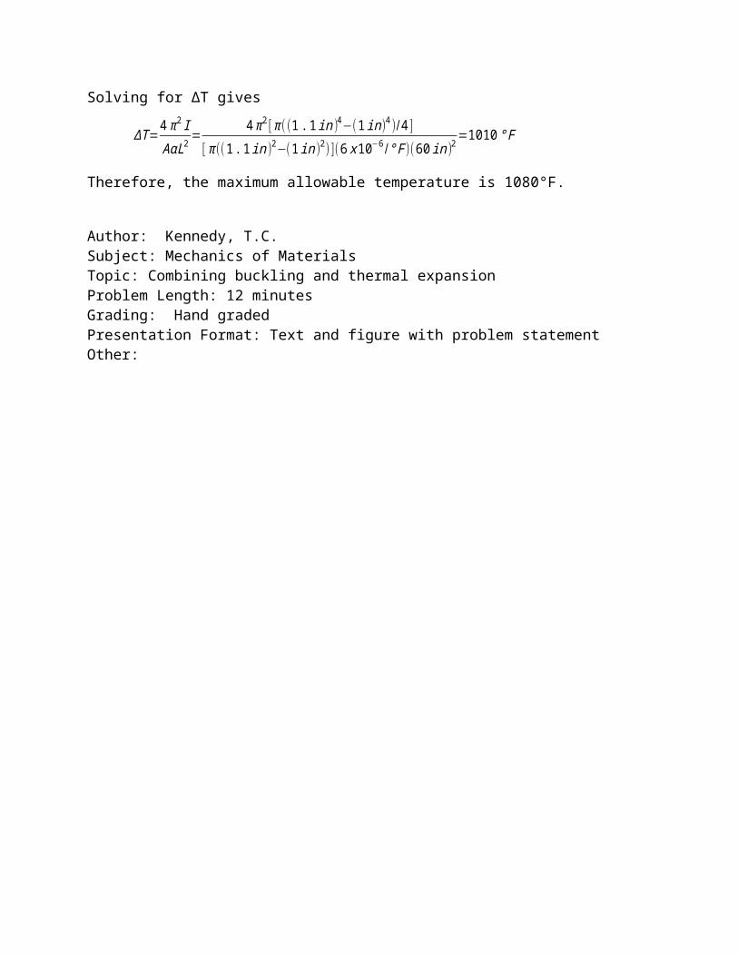
If the pipe were unconstrained, it would get longer due to thermal expansion. This is prevented by the constraint which effectively provides some unknown axial compressive force P. The superposition of these two effects is shown in the figure below.
The resulting net elongation would be given as
δ=αLΔT−PL/ EA=0
Solving this for the axial load P gives
P=EA αΔT
Since this bar is effectively clamped at both ends, the critical for bucking is
Pcrit=4 π2 EI / L2
For the bar to buckle, P must equal Pcrit.
EA αΔT=4 π 2 EI /L2
Solving for ∆T gives
ΔT =4 π2 IAαL2=
4 π2 [ π ((1 .1 in )4−(1in )4 )/4 ][ π ((1 .1 in)2−(1 in)2) ](6 x 10−6 /° F )(60 in)2=1010 ° F
Therefore, the maximum allowable temperature is 1080°F.
Author: Kennedy, T.C.Subject: Mechanics of MaterialsTopic: Combining buckling and thermal expansion Problem Length: 12 minutesGrading: Hand gradedPresentation Format: Text and figure with problem statementOther:
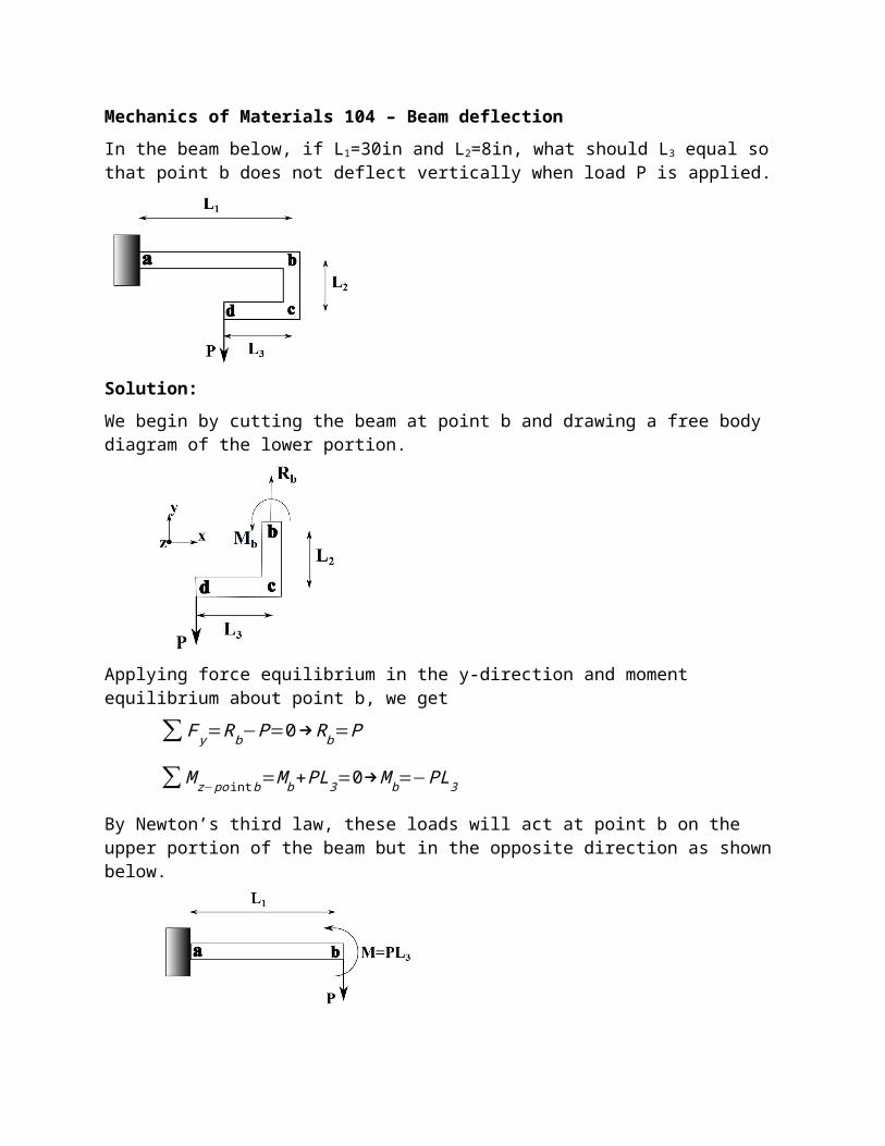
Mechanics of Materials 104 – Beam deflection
In the beam below, if L1=30in and L2=8in, what should L3 equal so that point b does not deflect vertically when load P is applied.
Solution:
We begin by cutting the beam at point b and drawing a free body diagram of the lower portion.
Applying force equilibrium in the y-direction and moment equilibrium about point b, we get
∑ F y=Rb−P=0→Rb=P
∑ M z−po int b=M b+PL3=0→M b=−PL3
By Newton’s third law, these loads will act at point b on the upper portion of the beam but in the opposite direction as shown below.
We now address the problem of finding the end deflection of a cantilever beam of length L1 subjected to an end force and end moment. We can use a beam deflection table and superposition to get the end deflection as
vb=PL1
3
3 EI−
PL3 L12
2EI
Setting vb equal to zero and solving for L3 gives L3=2L1/3. Therefore, we conclude the L3 should
equal 20in.
Author: Kennedy, T.C.Subject: Mechanics of MaterialsTopic: Beam deflection Problem Length: 5 minutesGrading: Hand gradedPresentation Format: Text and figure with problem statementOther:
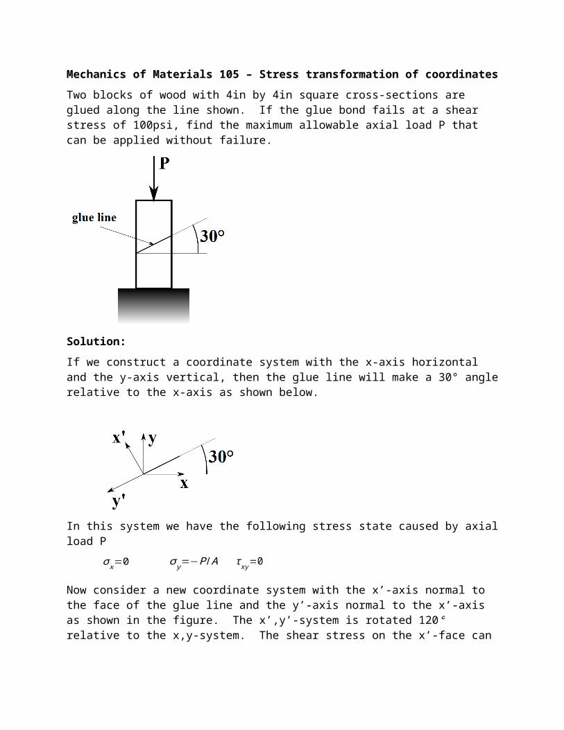
Mechanics of Materials 105 – Stress transformation of coordinates
Two blocks of wood with 4in by 4in square cross-sections are glued along the line shown. If the glue bond fails at a shear stress of 100psi, find the maximum allowable axial load P that can be applied without failure.
Solution:
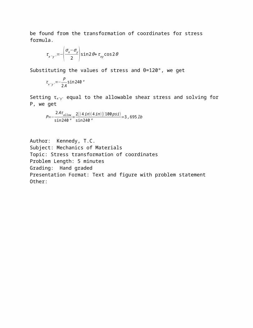
If we construct a coordinate system with the x-axis horizontal and the y-axis vertical, then the glue line will make a 30° angle relative to the x-axis as shown below.
In this system we have the following stress state caused by axial load P
σ x=0 σ y=−P/A τ xy=0
Now consider a new coordinate system with the x’-axis normal to the face of the glue line and the y’-axis normal to the x’-axis as shown in the figure. The x’,y’-system is rotated 120° relative to the x,y-system. The shear stress on the x’-face can be found from the transformation of coordinates for stress formula.
τ x ' y '=−( σ x−σ y
2 )sin 2θ+τ xy cos2θ
Substituting the values of stress and θ=120°, we get
τ x ' y '=− P2 A
sin240 °
Setting τx’y’ equal to the allowable shear stress and solving for P, we get
P=−2 Aτallow
sin 240°=
2 [( 4 in )(4 in )](100 psi)sin 240 °
=3 ,695 lb
Author: Kennedy, T.C.Subject: Mechanics of MaterialsTopic: Stress transformation of coordinatesProblem Length: 5 minutesGrading: Hand gradedPresentation Format: Text and figure with problem statementOther:
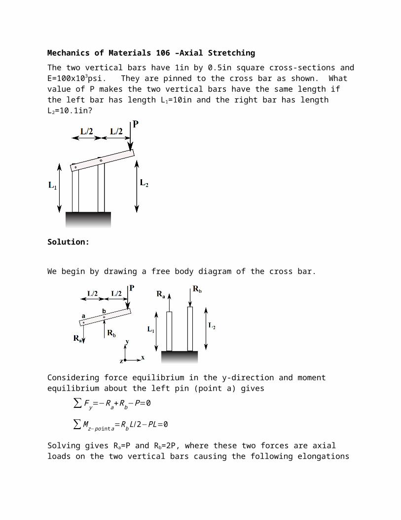
Mechanics of Materials 106 –Axial Stretching
The two vertical bars have 1in by 0.5in square cross-sections and E=100x103psi. They are pinned to the cross bar as shown. What value of P makes the two vertical bars have the same length if the left bar has length L1=10in and the right bar has length L2=10.1in?
Solution:
We begin by drawing a free body diagram of the cross bar.
Considering force equilibrium in the y-direction and moment equilibrium about the left pin (point a) gives
∑ F y=−Ra+Rb−P=0
∑ M z− po int a=Rb L/2−PL=0
Solving gives Ra=P and Rb=2P, where these two forces are axial loads on the two vertical bars causing the following elongations
δ1=PL 1 /EA δ 2=−2 PL2 / EA
The final lengths of the two bars are
L1 final=L1+δ 1 L2 final=L2+δ2
Setting these two lengths equal to each other gives
L1+PL1 /EA=L2−2 PL2 /EA
Solving for P gives
P=( L2−L1 )EA
L1+2L2=
(10. 1in−10 in )(100 x103 psi )[(1 in )(0 .5 in) ]10in+2(10 .1 in )
=167 lb
Author: Kennedy, T.C.Subject: Mechanics of MaterialsTopic: Axial StretchingProblem Length: 10 minutesGrading: Hand gradedPresentation Format: Text and figure with problem statementOther:
Mechanics of Materials 107 – Torsion and Mohr’s circle
The cylinder has an inner radius of 1in and an outer radius of 1.1in. It is subjected to an axial load P=1000lb and a torque T=1000inlb. A crack is found in the cylinder that makes an angle θ relative to an axis parallel to the central axis of the cylinder. What would be the ideal orientation angle θ of the crack so that does not tend to propagate? Tension normal to the crack tends to make the crack propagate. Shear parallel to the crack tends to make the crack propagate. Compression normal to the crack has no effect.
Solution:
We begin by finding the stresses caused by the axial load P and the torsional load T acting on the cylinder.
σ x=P/ A=1000 lbπ [ (1.1 in)2−(1in)2 ]
=1 ,515 psi
τ xy=TrJ
=(1000 inlb)(1 .1 in )
π [ (1. 1in )4−(1 in )4 ] /2=1 ,507 psi
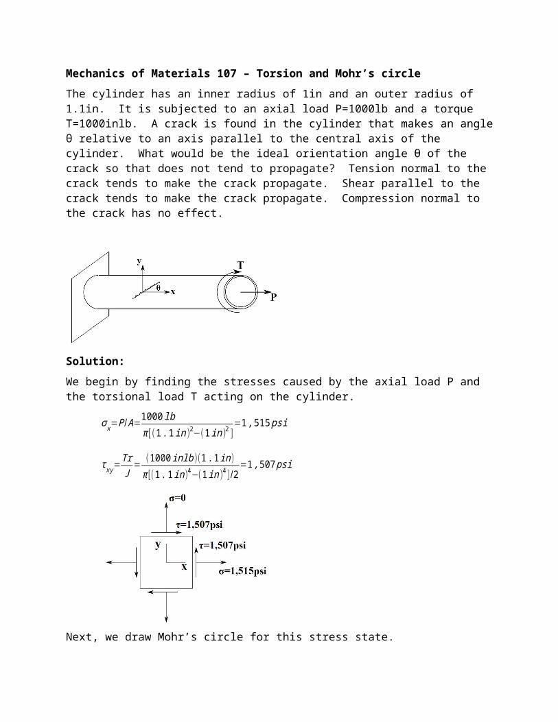
Next, we draw Mohr’s circle for this stress state.
Now, we look for a point on the surface of the circle where there is neither normal tension stress nor shear stress. This is the point labeled x’-face on the circle (which has normal compressive stress, but that is ok). This face is 243° counterclockwise from the x-face on the circle. The orientation of the normal to this face on the cylinder is 243°/2 counterclockwise from the x-axis. This means that the line of the crack should make an angle of θ=243°/2-90°=31.5° counterclockwise from the x-axis.
Author: Kennedy, T.C.Subject: Mechanics of MaterialsTopic: Torsion and Mohr’s circleProblem Length: 15 minutesGrading: Hand gradedPresentation Format: Text and figure with problem statementOther:
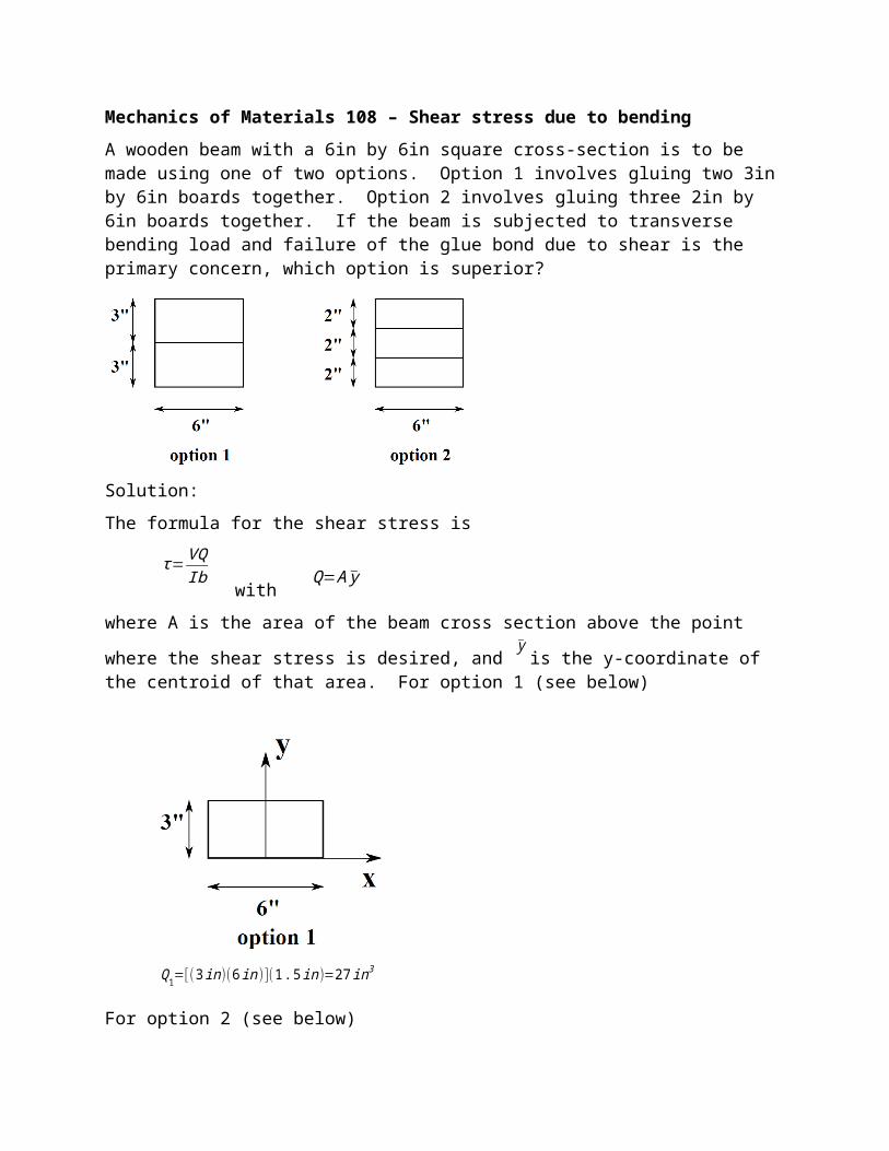
Mechanics of Materials 108 – Shear stress due to bending
A wooden beam with a 6in by 6in square cross-section is to be made using one of two options. Option 1 involves gluing two 3in by 6in boards together. Option 2 involves gluing three 2in by 6in boards together. If the beam is subjected to transverse bending load and failure of the glue bond due to shear is the primary concern, which option is superior?
Solution:
The formula for the shear stress is
τ=VQIb
with Q=A y
where A is the area of the beam cross section above the point where the shear stress is desired,
and y
is the y-coordinate of the centroid of that area. For option 1 (see below)
Q1=[(3 in )(6 in )](1.5 in )=27 in3
For option 2 (see below)
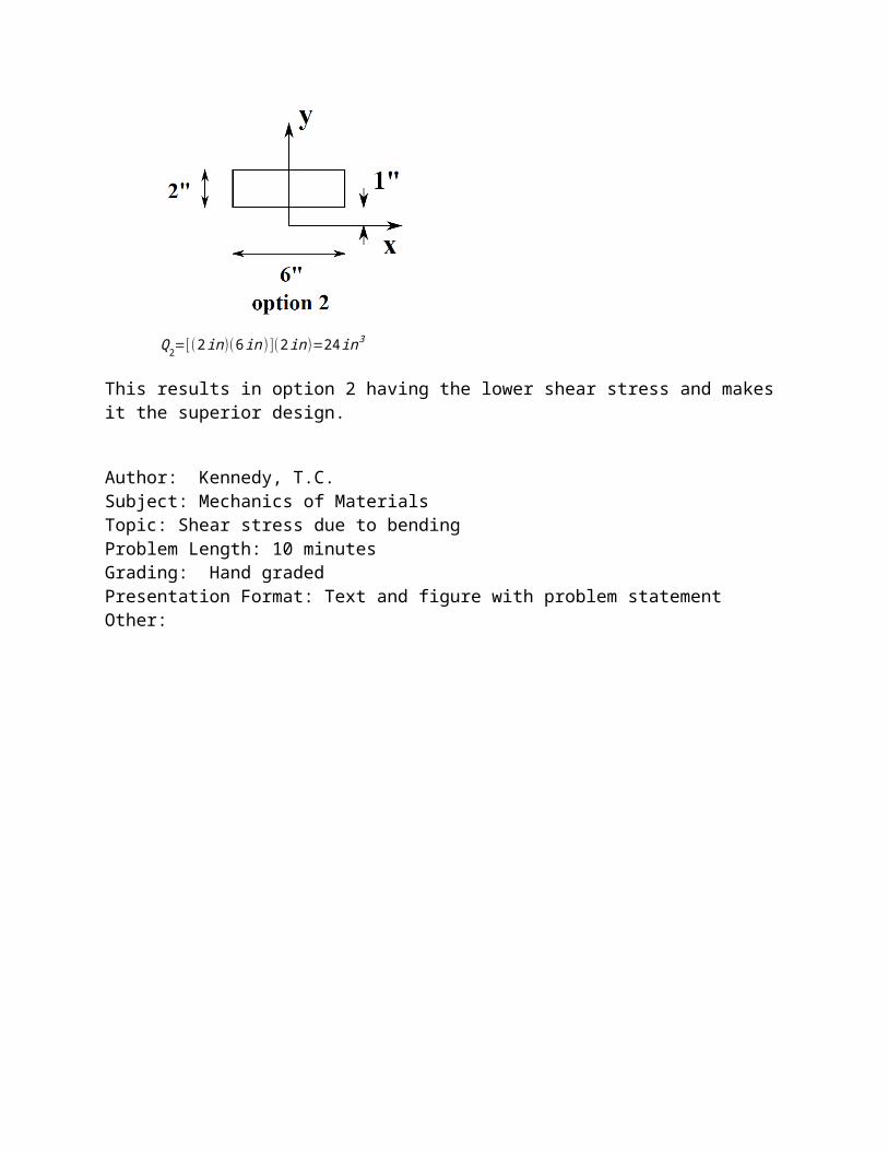
Q2=[(2 in )(6 in )](2in )=24 in3
This results in option 2 having the lower shear stress and makes it the superior design.
Author: Kennedy, T.C.Subject: Mechanics of MaterialsTopic: Shear stress due to bending Problem Length: 10 minutesGrading: Hand gradedPresentation Format: Text and figure with problem statementOther:
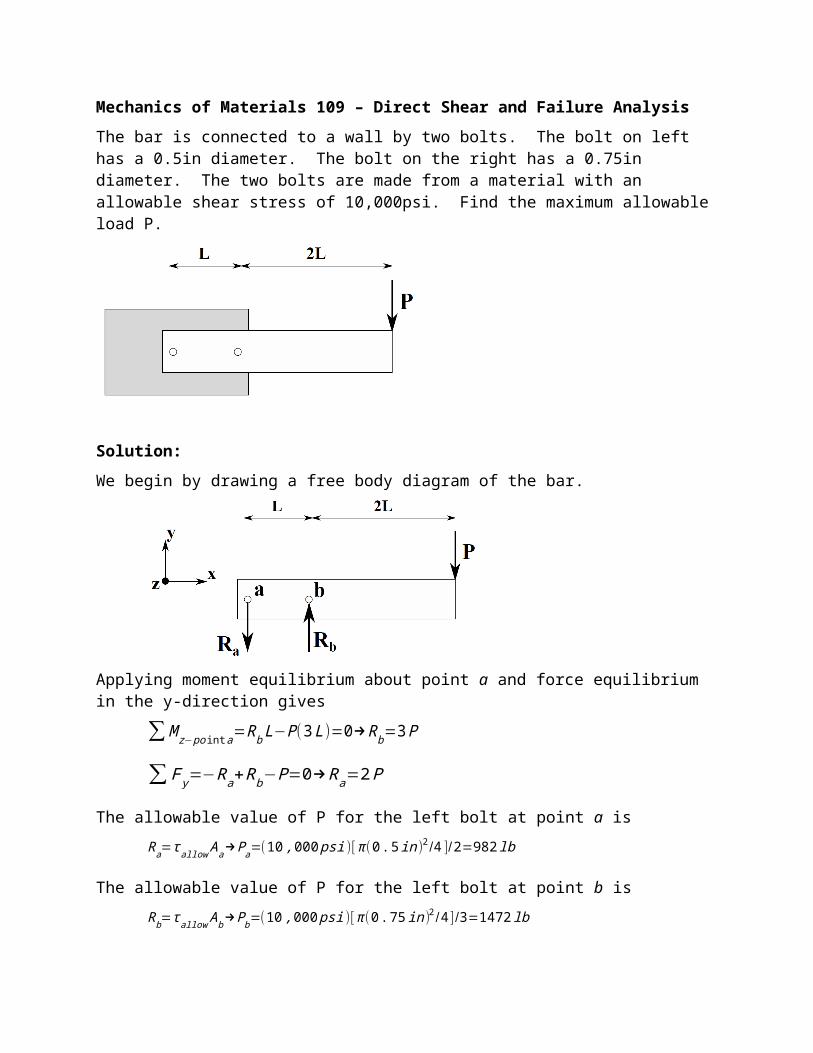
Mechanics of Materials 109 – Direct Shear and Failure Analysis
The bar is connected to a wall by two bolts. The bolt on left has a 0.5in diameter. The bolt on the right has a 0.75in diameter. The two bolts are made from a material with an allowable shear stress of 10,000psi. Find the maximum allowable load P.
Solution:
We begin by drawing a free body diagram of the bar.
Applying moment equilibrium about point a and force equilibrium in the y-direction gives
∑ M z− po int a=Rb L−P (3 L )=0→Rb=3 P
∑ F y=−Ra+Rb−P=0→Ra=2 P
The allowable value of P for the left bolt at point a is
Ra=τallow Aa→Pa=(10 ,000 psi )[π (0 .5in)2 /4 ] /2=982 lb
The allowable value of P for the left bolt at point b is
Rb=τallow Ab→Pb=(10 ,000 psi )[ π (0 .75in)2 /4 ] /3=1472 lb
Therefore, the maximum allowable value of P is 982lb.
Author: Kennedy, T.C.Subject: Mechanics of MaterialsTopic: Direct Shear and Failure Analysis
Problem Length: 10 minutesGrading: Hand gradedPresentation Format: Text and figure with problem statementOther:
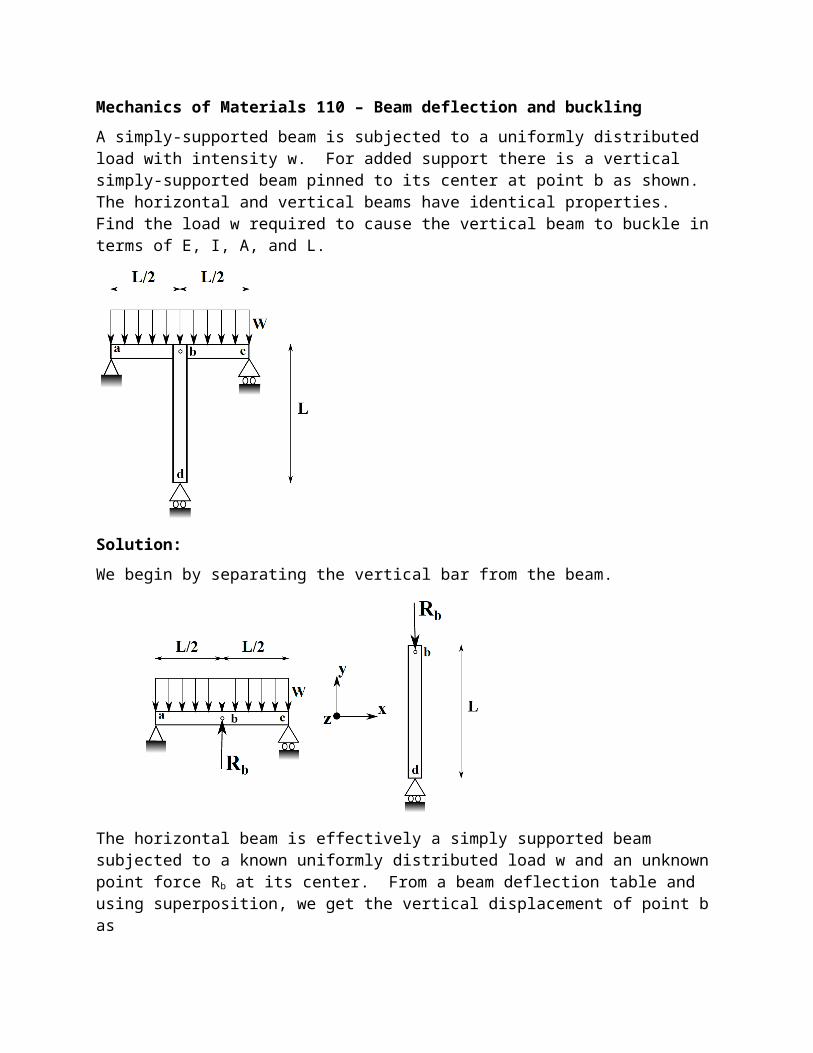
Mechanics of Materials 110 – Beam deflection and buckling
A simply-supported beam is subjected to a uniformly distributed load with intensity w. For added support there is a vertical simply-supported beam pinned to its center at point b as shown. The horizontal and vertical beams have identical properties. Find the load w required to cause the vertical beam to buckle in terms of E, I, A, and L.
Solution:
We begin by separating the vertical bar from the beam.
The horizontal beam is effectively a simply supported beam subjected to a known uniformly distributed load w and an unknown point force Rb at its center. From a beam deflection table and using superposition, we get the vertical displacement of point b as
vb=5wL4
384 EI−
Rb L3
48 EI
The vertical bar is a bar subjected to an unknown axial load Rb. The shortening of this bar is
δ b=Rb L /EA
Compatibility of deformation requires vb=δb which gives
5 wL4
384 EI−
Rb L3
48EI=Rb L/ EA
Solving for Rb gives
Rb=5wL3
384 I ( L2
48 I+ 1
A )−1
The vertical bar will buckle when Rb reaches the buckling load for a simply supported beam, i.e.,
Rb=5wL3
384 I ( L2
48 I+ 1
A )−1
= π2 EIL2
Solving for w gives
w=384 π2 EI 2
5 L5 ( L2
48 I+ 1
A )Author: Kennedy, T.C.Subject: Mechanics of MaterialsTopic: Beam deflection and bucklingProblem Length: 15 minutesGrading: Hand gradedPresentation Format: Text and figure with problem statementOther:
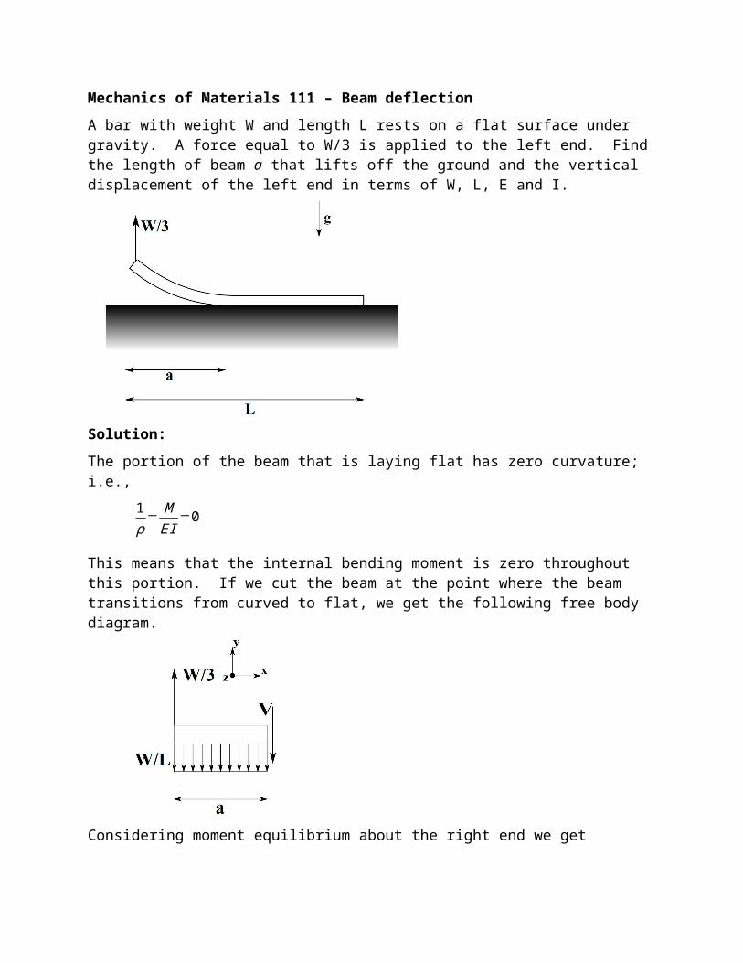
Mechanics of Materials 111 – Beam deflection
A bar with weight W and length L rests on a flat surface under gravity. A force equal to W/3 is applied to the left end. Find the length of beam a that lifts off the ground and the vertical displacement of the left end in terms of W, L, E and I.
Solution:
The portion of the beam that is laying flat has zero curvature; i.e.,
1ρ= M
EI=0
This means that the internal bending moment is zero throughout this portion. If we cut the beam at the point where the beam transitions from curved to flat, we get the following free body diagram.
Considering moment equilibrium about the right end we get
∑ M z−rightend=−W3
a+[W aL ( a
2 ) ]=0
Solving for a gives a=2L/3. At the point where the beam transitions from curved to flat, both the displacement and the slope are equal to zero. Thus, the beam behaves as if it were cantilevered from this point as shown below.
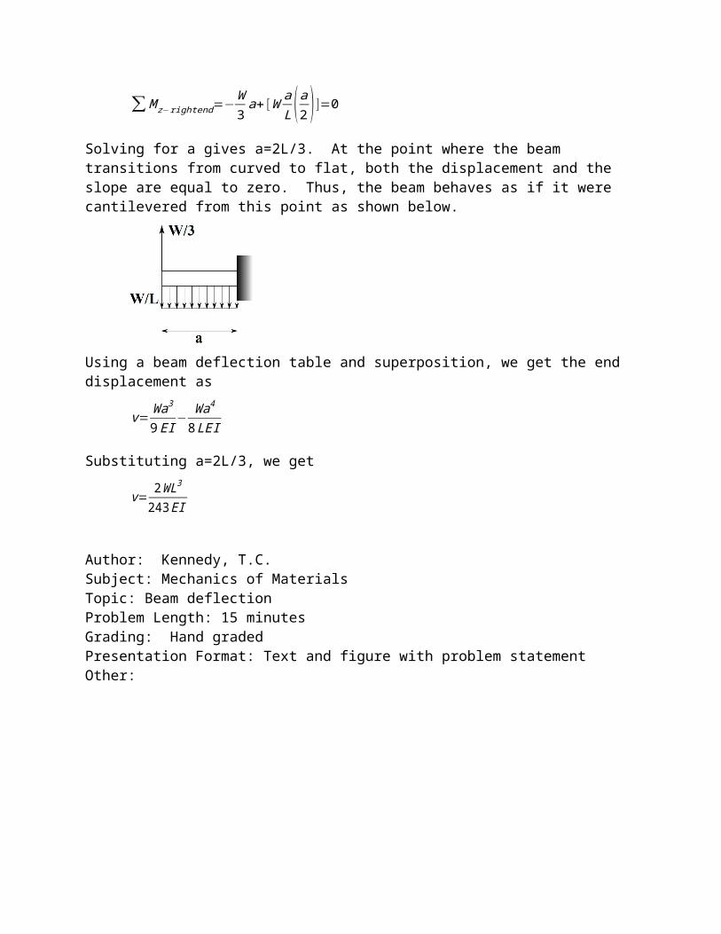
Using a beam deflection table and superposition, we get the end displacement as
v=Wa3
9EI− Wa4
8LEI
Substituting a=2L/3, we get
v= 2WL3
243 EI
Author: Kennedy, T.C.Subject: Mechanics of MaterialsTopic: Beam deflection Problem Length: 15 minutesGrading: Hand gradedPresentation Format: Text and figure with problem statementOther:
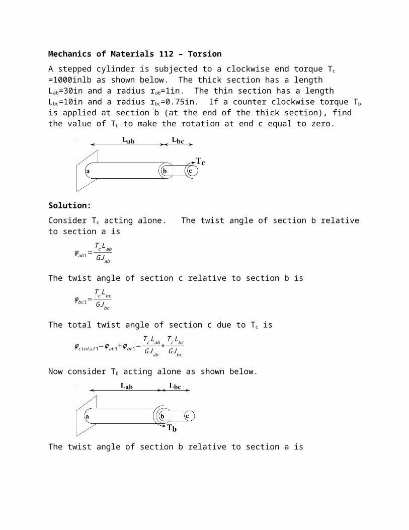
Mechanics of Materials 112 – Torsion
A stepped cylinder is subjected to a clockwise end torque Tc =1000inlb as shown below. The thick section has a length Lab=30in and a radius rab=1in. The thin section has a length Lbc=10in and a radius rbc=0.75in. If a counter clockwise torque Tb is applied at section b (at the end of the thick section), find the value of Tb to make the rotation at end c equal to zero.
Solution:
Consider Tc acting alone. The twist angle of section b relative to section a is
ϕab 1=Tc Lab
GJ ab
The twist angle of section c relative to section b is
ϕbc 1=T c Lbc
GJbc
The total twist angle of section c due to Tc is
ϕctotal 1=ϕab1+ϕbc1=Tc Lab
GJ ab+
T c Lbc
GJbc
Now consider Tb acting alone as shown below.
The twist angle of section b relative to section a is
ϕab 2=−T b Lab
GJab
The twist angle of section c relative to section b is
ϕbc 2=0
The total twist angle of section c due to Tb is
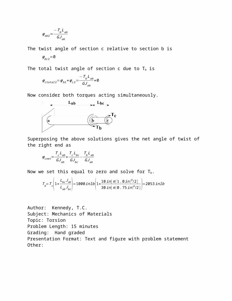
ϕctotal 2=ϕb 2+ϕc 2=−T b Lab
GJab+0
Now consider both torques acting simultaneously.
Superposing the above solutions gives the net angle of twist of the right end as
ϕcnet=T c Lab
GJab+
Tc Lbc
GJ bc−
T b Lab
GJ ab
Now we set this equal to zero and solve for Tb.
T b=T c(1+Lbc J ab
Lab Jbc)=1000inlb(1+10in [ π (1 . 0in)4 /2 ]
30in [ π ( 0. 75 in )4 /2] )=2053 inlb
Author: Kennedy, T.C.Subject: Mechanics of MaterialsTopic: TorsionProblem Length: 15 minutesGrading: Hand gradedPresentation Format: Text and figure with problem statementOther:
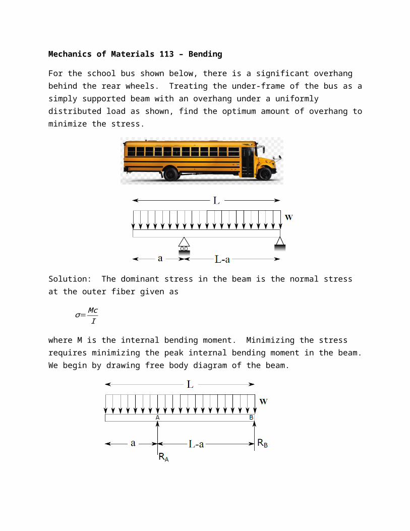
Mechanics of Materials 113 – Bending
For the school bus shown below, there is a significant overhang behind the rear wheels. Treating the under-frame of the bus as a simply supported beam with an overhang under a uniformly distributed load as shown, find the optimum amount of overhang to minimize the stress.
Solution: The dominant stress in the beam is the normal stress at the outer fiber given as
σ= McI
where M is the internal bending moment. Minimizing the stress requires minimizing the peak internal bending moment in the beam. We begin by drawing free body diagram of the beam.
We will replace the distributed load by statically equivalent point loads.
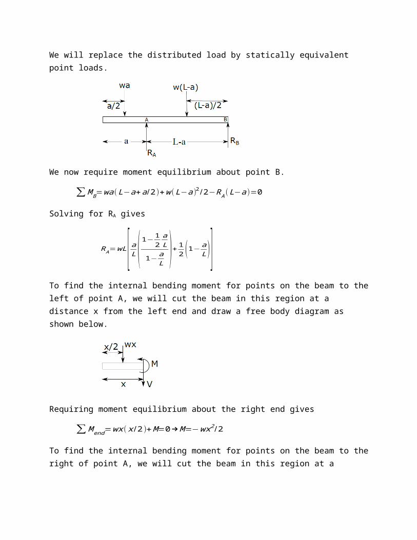
We now require moment equilibrium about point B.
∑ M B=wa(L−a+a /2 )+w (L−a )2/2−R A(L−a )=0
Solving for RA gives
RA=wL [ aL (1−
12
aL
1− aL
)+ 12 (1−a
L )]To find the internal bending moment for points on the beam to the left of point A, we will cut the beam in this region at a distance x from the left end and draw a free body diagram as shown below.
Requiring moment equilibrium about the right end gives
∑ M end=wx ( x /2 )+ M=0→M=−wx2 /2
To find the internal bending moment for points on the beam to the right of point A, we will cut the beam in this region at a distance x from the left end and draw a free body diagram as shown below.
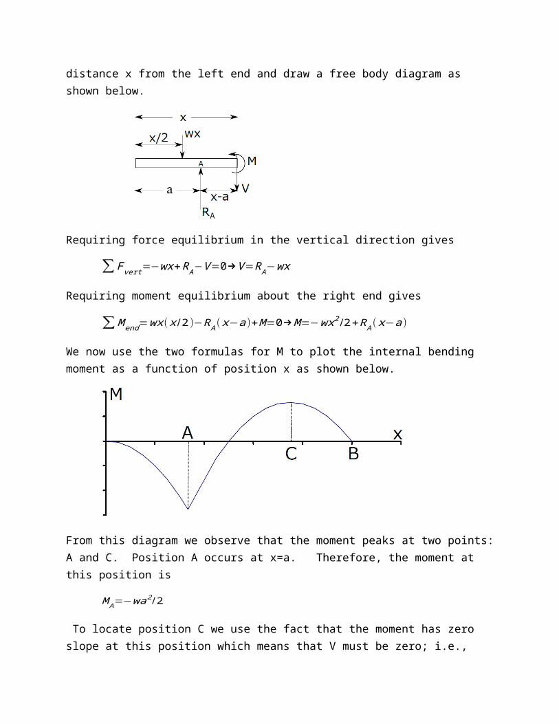
Requiring force equilibrium in the vertical direction gives
∑ Fvert=−wx+RA−V=0→V =RA−wx
Requiring moment equilibrium about the right end gives
∑ M end=wx ( x /2 )−RA( x−a)+M =0→M=−wx2 /2+RA( x−a)
We now use the two formulas for M to plot the internal bending moment as a function of position x as shown below.
From this diagram we observe that the moment peaks at two points: A and C. Position A occurs at x=a. Therefore, the moment at this position is
M A=−wa2 /2
To locate position C we use the fact that the moment has zero slope at this position which means that V must be zero; i.e.,
RA−wx=0
Solving for x gives x=RA/w. Therefore, the moment at this position is
MC=−w(RA /w)2 /2+R A(RA /w−a)
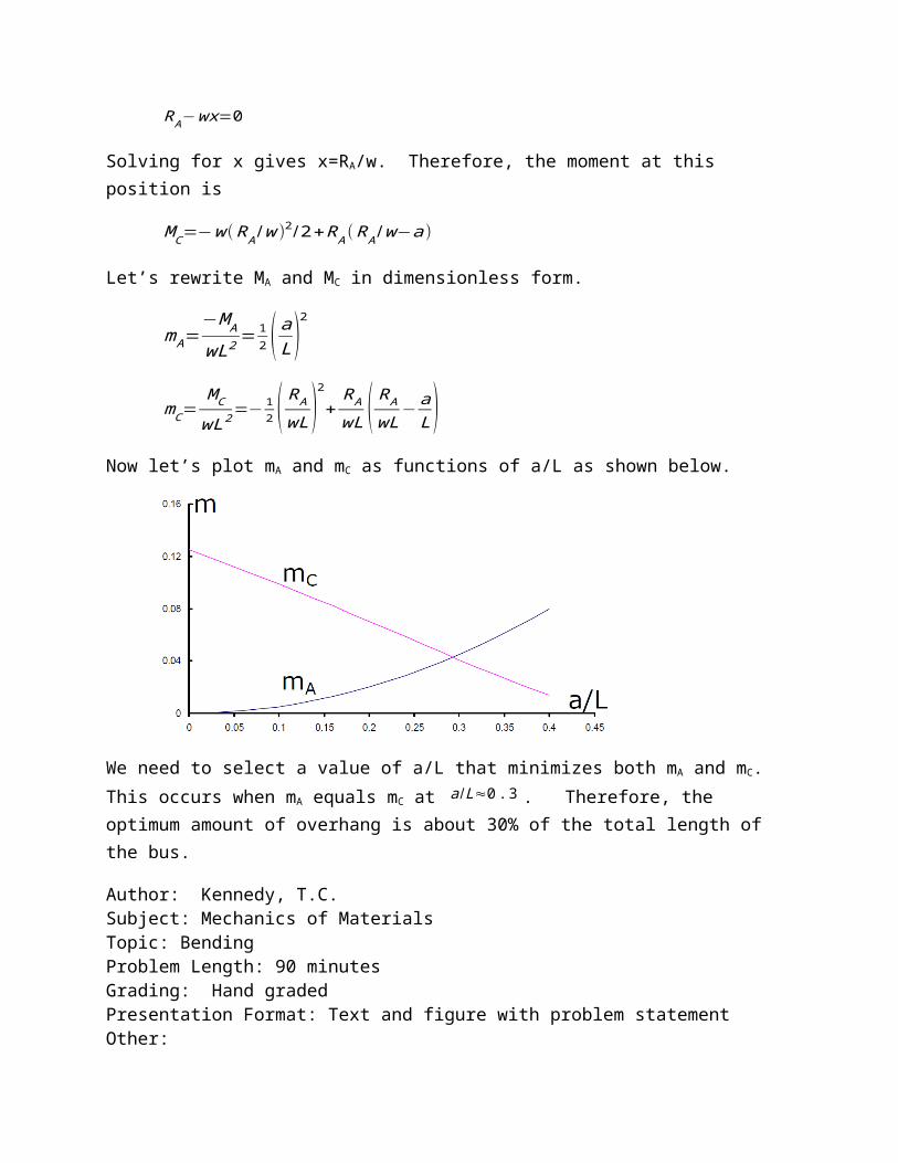
Let’s rewrite MA and MC in dimensionless form.
mA=−M A
wL2 = 12 ( a
L )2
mC=MC
wL2 =−12 ( R A
wL)2
+RA
wL ( RA
wL−a
L )Now let’s plot mA and mC as functions of a/L as shown below.
We need to select a value of a/L that minimizes both mA and mC. This occurs when mA equals mC at a /L≈0 . 3 . Therefore, the optimum amount of overhang is about 30% of the total length of the bus.
Author: Kennedy, T.C.Subject: Mechanics of MaterialsTopic: BendingProblem Length: 90 minutesGrading: Hand gradedPresentation Format: Text and figure with problem statementOther: