Embed Size (px)
Citation preview

INDIAN INSTITUTE OF TECHNOLOGY – DELHITitle of study a) Study of compressible flow through a converging-diverging nozzle.
b) Study of Performance of Cooling Packs used in PCs.Experiment no. Date of experiment Date of submission Course coordinator
# 9 Dr. PMV Subbarao (Professor)Department of Mechanical Engg.
COURSE – Experimental Methods in Thermal Engineering (MEL - 705)
-------------Cycle----------
a) Objective1. To study flow characteristics through a convergent, and convergent-divergent nozzle with
both subsonic and supersonic flow.2. To study the phenomenon of shock, and how to locate position of shock.
Introduction
Flow through nozzles a variant of internal flow with additional effect of compressibility and possible
presence of shocks. Such situations occur in gas/vapour flows when there is a constriction in a
passage across which there is a pressure difference e.g. flows through turbine/compressor blades,
nozzles, rupture of high pressure vessel or tyre etc.
A compressible flow is that flow in which density of fluid changes during flow. All real fluids are
compressible to some extent and their density will change with change in pressure and temperature. a
compressible flow fluid, such as air can be taken as incompressible with constant density if change in
temperature and duration are small and acceleration is low .In other words, if mach no. is small,
compressible fluids can be treated as incompressible. However, flow of gases/vapour through
nozzles/turbines/compressor blades etc.at high velocity has high Mach number and there
compressibility affects the drag coeff. of bodies by the formation of shockwaves and discharge coeff.
(cd) of measuring devices such as orifice meters/pitot tubes etc
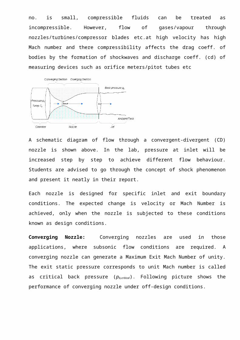
A schematic diagram of flow through a convergent-divergent (CD) nozzle is shown above. In the lab,
pressure at inlet will be increased step by step to achieve different flow behaviour. Students are
advised to go through the concept of shock phenomenon and present it neatly in their report.
Each nozzle is designed for specific inlet and exit boundary conditions. The expected change is
velocity or Mach Number is achieved, only when the nozzle is subjected to these conditions known
as design conditions.
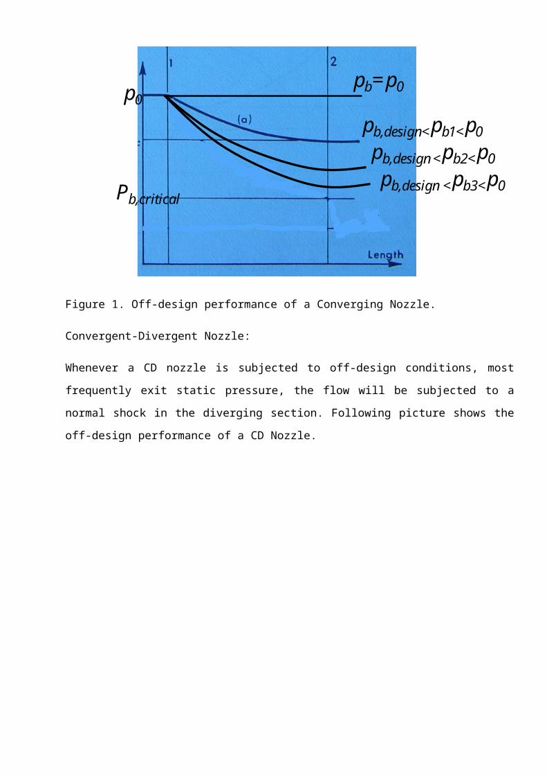
Converging Nozzle: Converging nozzles are used in those applications, where subsonic flow
conditions are required. A converging nozzle can generate a Maximum Exit Mach Number of unity.
The exit static pressure corresponds to unit Mach number is called as critical back pressure (pb,critical).
Following picture shows the performance of converging nozzle under off-design conditions.
p0
Pb,critical
pb=p0
pb,design<pb1<p0pb,design <pb2<p0pb,design <pb3<p0
Figure 1. Off-design performance of a Converging Nozzle.
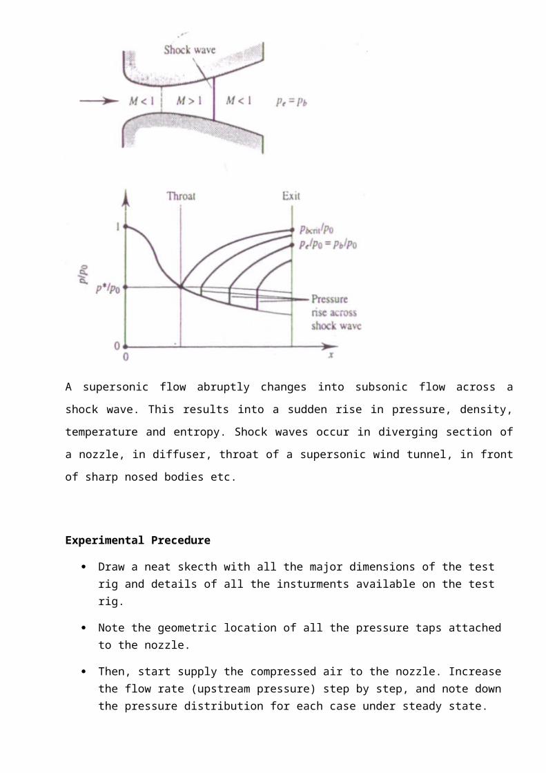
Convergent-Divergent Nozzle:
Whenever a CD nozzle is subjected to off-design conditions, most frequently exit static pressure, the
flow will be subjected to a normal shock in the diverging section. Following picture shows the off-
design performance of a CD Nozzle.
A supersonic flow abruptly changes into subsonic flow across a shock wave. This results into a
sudden rise in pressure, density, temperature and entropy. Shock waves occur in diverging section of
a nozzle, in diffuser, throat of a supersonic wind tunnel, in front of sharp nosed bodies etc.
Experimental Precedure
Draw a neat skecth with all the major dimensions of the test rig and details of all the insturments available on the test rig.
Note the geometric location of all the pressure taps attached to the nozzle.
Then, start supply the compressed air to the nozzle. Increase the flow rate (upstream pressure) step by step, and note down the pressure distribution for each case under steady state.
Repeat the excercise for atleast four different upstream pressures for converging nozzle.
Repeat the excercise for atleast four different upstream pressures for converging-diverging nozzle ranging from subsonic to supersonic flow conditions
Data Analysis
Propose a methodology for locating the shock position when nozzle geometry and inlet/ exit pressures are known.
Uncertainty analysis.
b) Objective3. To study cooling characteristics of cooling packs used in Personal Computers. 4. To develop a relation between thermal resistance and flow rate through a cooling pack.5. To compare thermal performance of two cooling packs.
Introduction:
Modern electronic industry uses variety of fans for cooling the CPUs and other electronic components. The role thermal engineering in development of cooling packs for PCs is very important and critical. Following picture shows the specifications of a cooling pack.
Pentium 4 burns some 55 W and therefore it needs some good cooling devices.
Design Calculations for Fin Arrays – Thermal Resistance
In order to select the appropriate heat sink, the thermal designer mustfirst determine the maximum allowable heat sink thermal resistance. To do this it is necessary to know the maximum allowable module case temperature, Tcase,
the module power dissipation, Pmod, and
the thermal resistance at the module-to-heat sink interface, Rint.
The maximum allowable temperature at the heat sink attachment surface, Tbase, is given by
intmod RPTT casebase

Experimental Precedure
Draw a neat skecth with all the major dimensions of the test rig and details of all the insturments available on the test rig.
Note the geometric location of all the pressure taps attached to the rig.
Then, start power supply to the heater and run the fan and specified flow condtions.
Vary the flow rate and heating rate step by step, and note down the base temperature and flow condtions.
Repeat the excercise for atleast four different combinations of flow rates and heating rates.
Repeat the excercise for two different cooling packs.
Data Analysis
Calculate thermal resistance at various conditions. Draw performance curves. Uncertainty analysis.
The maximum allowable heat sink resistance, Rmax, is then given by
The thermal resistance of the heat sink is given by
parameters the gap, b, between the fins may be determined from


![Developing laminar flow in the inlet length of a smooth pipepmvs/courses/mel705/developing...Martin [3] and Vrentas and Duda [11] highlight the work ofvarious investi- gators in this](https://img.pdfslide.net/doc/110x75/60d9682730dae44e6c11d62e/developing-laminar-flow-in-the-inlet-length-of-a-smooth-pipe-pmvscoursesmel705developing.jpg)