Embed Size (px)
Citation preview
Wedge Brakes
BSM-0381E SERVICE MANUAL
September 2018
Wedge 15" & 410 mm
Table of Contents
i
Table of ContentsService Notes ...................................................ii
Asbestos and Non-Asbestos Fibers Warning ......iii
Service Precautions .......................................... v
Section 1: Introduction .................................... 11.1 Operation ..................................................11.2 Technical Specifi cations .............................11.3 Part Numbering ..........................................21.4 Exploded Views ..........................................31.5 Wedge Brake Operation ..............................71.6 Automatic Adjustment ................................8
Section 2: Disassembly .................................... 92.1 Remove Brake Shoes .................................92.2 Remove Air Chamber & Wedge Assembly . 102.3 Disassemble Brake ................................. 10
Section 3: Clean & Inspect ............................. 123.1 Clean ...................................................... 123.2 Corrosion Protection ............................... 123.3 Wedge Assembly ..................................... 133.4 Actuator Components ............................. 133.5 Brake Shoes and Linings ......................... 133.6 Shoe Hold Down Clip ............................... 13
Section 4: Assembly ....................................... 144.1 Single Actuated Brakes ........................... 144.2 Dual Actuated Brakes ............................. 144.3 Lubrication ............................................. 154.4 Assemble Brake ...................................... 164.5 Assemble Wedge Assembly & Air Chamber 194.6 Assemble Brake Shoes ............................ 20
Section 5: Maintenance ................................. 215.1 Lubrication ............................................. 215.2 Preventative Maintenance ....................... 235.3 Troubleshooting ...................................... 25
Appendix ....................................................... 28Torque Specifi cations .................................... 28
Service Notes
ii
Service Notes
This service manual describes the service and repair procedures for the Heavy Duty Wedge Drum Brakes. The information contained in this manual is current at the time of publication and is subject to change without notice or liability.
Follow all company procedures when servicing or repairing equipment or components. Understand all instructions before performing any product service. Some procedures require the use of special tools for safe and correct ser-vice. Failure to use special tools when required can cause serious personal injury to service personnel, as well as, damage to equipment and components.
The instructions contained in this service manual are intended for use by skilled and experienced mechanics knowledgeable in the installation, repair, and replacement of the AxleTech product described herein.
! DANGERInstallation, maintenance, and replacement of such prod-ucts requires a high degree of skill and experience. The consequences of improper installation, maintenance, or replacement (including the use of inferior or substandard components) are grave and can result in product failure and resulting loss of control of the vehicle, possible injury or death of persons, and/or possible future or additional product damage.
AxleTech does not authorize anyone, other than highly skilled and experienced individuals, to attempt to utilize the instructions contained in this manual for the installa-tion, maintenance, or replacement of the product de-scribed herein, and AxleTech shall have no liability of any kind for damages arising out of (or in connection with) any other use of the information contained in this manual.
UpdatesFor the latest version of this manual, please visit the AxleTech web site at www.axletech.com. AxleTech Customer Service can be reached at 800-540-2794 or via email at [email protected].
NotationsAxleTech International uses the following notation to warn the user of possible safety problems and to provide information that will prevent damage to equipment and components:
! DANGERA DANGER indicates a procedure that must be followed exactly or it will cause death or serious injury.
! WARNINGA WARNING indicates a procedure that must be followed exactly or it may cause death or serious injury.
! CAUTIONA CAUTION indicates a procedure that must be followed exactly to avoid damaging equipment or components.
NOTEA NOTE indicates an operation, procedure, or instruction that is important for proper service. A NOTE can also supply information that will help to make service quicker and easier.
Asbestos and Non-Asbestos Fibers Warning
iii
Asbestos and Non-Asbestos Fibers Warning
OSHA* Toxic and Hazardous Substances 29 CFR 1910.1001
Work practices and engineering controls for automotive brake and clutch inspection, disassembly, repair and assembly -- Mandatory
This mandatory appendix specifi es engineering controls and work practices that must be implemented by the employer during automotive brake and clutch inspection, disassembly, repair, and assembly operations.
Proper use of these engineering controls and work practices by trained employees will reduce employees’ asbestos exposure below the permissible exposure level during clutch and brake inspection, disassembly, repair, and assembly operations. The employer shall institute engineering controls and work practices using either the method set forth in paragraph [A] or paragraph [B] of this appendix, or any other method which the employer can demonstrate to be equivalent in terms of reducing employ-ee exposure to asbestos as defi ned and which meets the requirements described in paragraph [C] of this appendix, for those facilities in which no more than 5 pairs of brakes or 5 clutches are inspected, disassembled, reassembled and/or repaired per week, the method set forth in para-graph [D] of this appendix may be used:
[A] Negative Pressure Enclosure/HEPA Vacuum System Method
(1) The brake and clutch inspection, disassembly, repair, and assembly operations shall be enclosed to cover and contain the clutch or brake assembly and to prevent the release of asbestos fi bers into the worker’s breathing zone.
(2) The enclosure shall be sealed tightly and thoroughly in-spected for leaks before work begins on brake and clutch inspection, disassembly, repair, and assembly.
(3) The enclosure shall be such that the worker can clearly see the operation and shall provide impermeable sleeves through which the worker can handle the brake and clutch inspection, disassembly, repair and assembly. The integri-ty of the sleeves and ports shall be examined before work begins.
(4) A HEPA-fi ltered vacuum shall be employed to maintain the enclosure under negative pressure throughout the op-eration. Compressed-air may be used to remove asbestos fi bers or particles from the enclosure.
(5) The HEPA vacuum shall be used fi rst to loosen the as-bestos containing residue from the brake and clutch parts and then to evacuate the loosened asbestos containing material from the enclosure and capture the material in the vacuum fi lter.
(6) The vacuum’s fi lter, when full, shall be fi rst wetted with a fi ne mist of water, then removed and placed immedi-ately in an impermeable container, labeled according to paragraph (j)(5) of this section and disposed of according to paragraph (k) of this section.
(7) Any spills or releases of asbestos containing waste material from inside of the enclosure or vacuum hose or vacuum fi lter shall be immediately cleaned up and dis-posed of according to paragraph (k) of this section.
[B] Low Pressure/Wet Cleaning Method
(1) A catch basin shall be placed under the brake assem-bly, positioned to avoid splashes and spills.
(2) The reservoir shall contain water containing an organic solvent or wetting agent. The fl ow of liquid shall be con-trolled such that the brake assembly is gently fl ooded to prevent the asbestos-containing brake dust from becom-ing airborne.
(3) The aqueous solution shall be allowed to fl ow between the brake drum and brake support before the drum is removed.
(4) After removing the brake drum, the wheel hub and back of the brake assembly shall be thoroughly wetted to suppress dust.
Asbestos and Non-Asbestos Fibers Warning
iv
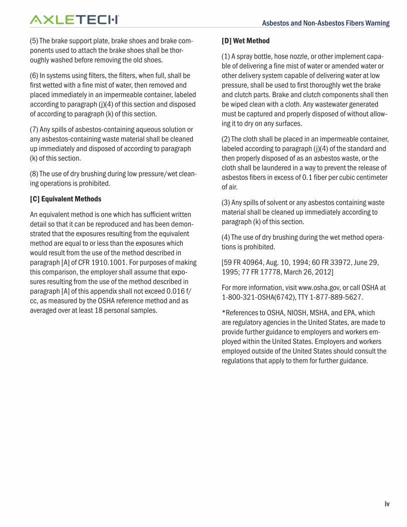
(5) The brake support plate, brake shoes and brake com-ponents used to attach the brake shoes shall be thor-oughly washed before removing the old shoes.
(6) In systems using fi lters, the fi lters, when full, shall be fi rst wetted with a fi ne mist of water, then removed and placed immediately in an impermeable container, labeled according to paragraph (j)(4) of this section and disposed of according to paragraph (k) of this section.
(7) Any spills of asbestos-containing aqueous solution or any asbestos-containing waste material shall be cleaned up immediately and disposed of according to paragraph (k) of this section.
(8) The use of dry brushing during low pressure/wet clean-ing operations is prohibited.
[C] Equivalent Methods
An equivalent method is one which has suffi cient written detail so that it can be reproduced and has been demon-strated that the exposures resulting from the equivalent method are equal to or less than the exposures which would result from the use of the method described in paragraph [A] of CFR 1910.1001. For purposes of making this comparison, the employer shall assume that expo-sures resulting from the use of the method described in paragraph [A] of this appendix shall not exceed 0.016 f/cc, as measured by the OSHA reference method and as averaged over at least 18 personal samples.
[D] Wet Method
(1) A spray bottle, hose nozzle, or other implement capa-ble of delivering a fi ne mist of water or amended water or other delivery system capable of delivering water at low pressure, shall be used to fi rst thoroughly wet the brake and clutch parts. Brake and clutch components shall then be wiped clean with a cloth. Any wastewater generated must be captured and properly disposed of without allow-ing it to dry on any surfaces.
(2) The cloth shall be placed in an impermeable container, labeled according to paragraph (j)(4) of the standard and then properly disposed of as an asbestos waste, or the cloth shall be laundered in a way to prevent the release of asbestos fi bers in excess of 0.1 fi ber per cubic centimeter of air.
(3) Any spills of solvent or any asbestos containing waste material shall be cleaned up immediately according to paragraph (k) of this section.
(4) The use of dry brushing during the wet method opera-tions is prohibited.
[59 FR 40964, Aug. 10, 1994; 60 FR 33972, June 29, 1995; 77 FR 17778, March 26, 2012]
For more information, visit www.osha.gov, or call OSHA at 1-800-321-OSHA(6742), TTY 1-877-889-5627.
*References to OSHA, NIOSH, MSHA, and EPA, which are regulatory agencies in the United States, are made to provide further guidance to employers and workers em-ployed within the United States. Employers and workers employed outside of the United States should consult the regulations that apply to them for further guidance.
Service Precautions
v
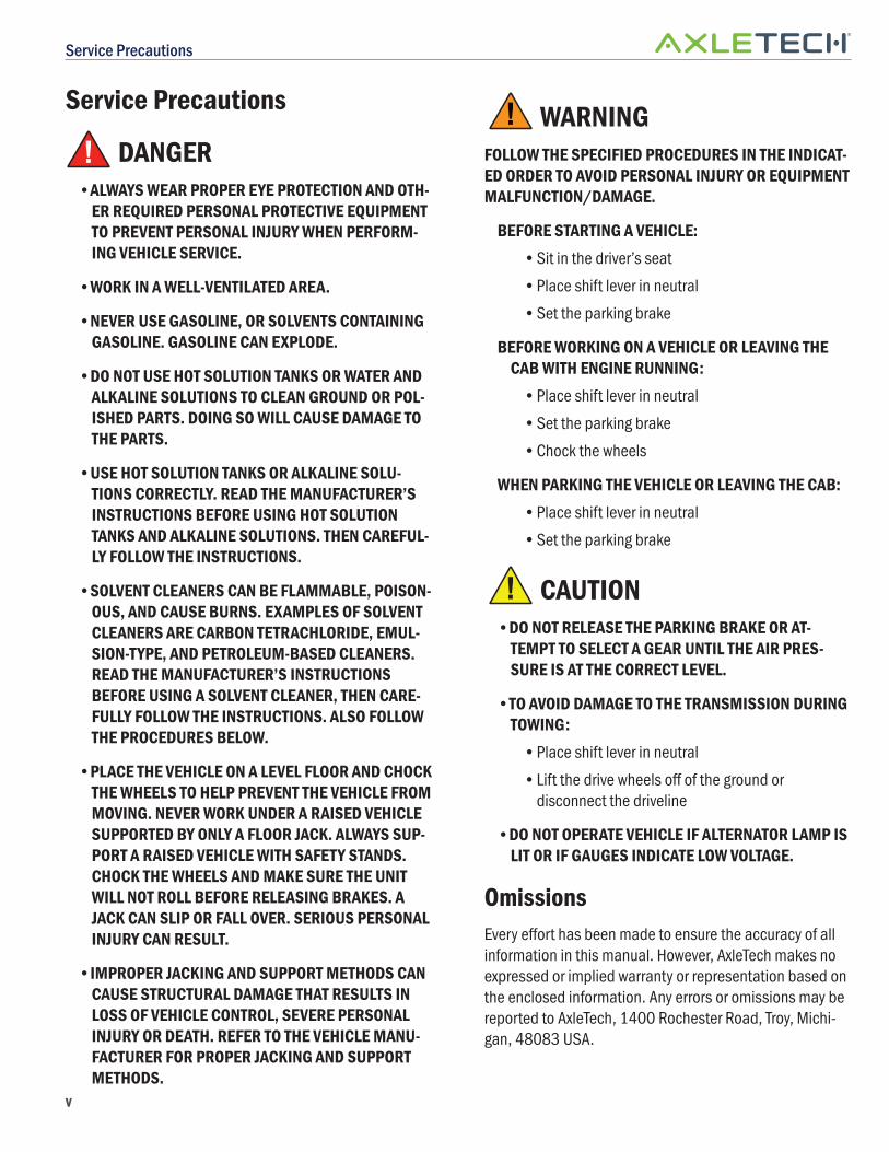
! WARNING
FOLLOW THE SPECIFIED PROCEDURES IN THE INDICAT-ED ORDER TO AVOID PERSONAL INJURY OR EQUIPMENT MALFUNCTION/DAMAGE.
BEFORE STARTING A VEHICLE:
• Sit in the driver’s seat
• Place shift lever in neutral
• Set the parking brake
BEFORE WORKING ON A VEHICLE OR LEAVING THE CAB WITH ENGINE RUNNING:
• Place shift lever in neutral
• Set the parking brake
• Chock the wheels
WHEN PARKING THE VEHICLE OR LEAVING THE CAB:
• Place shift lever in neutral
• Set the parking brake
! CAUTION
•DO NOT RELEASE THE PARKING BRAKE OR AT-TEMPT TO SELECT A GEAR UNTIL THE AIR PRES-SURE IS AT THE CORRECT LEVEL.
•TO AVOID DAMAGE TO THE TRANSMISSION DURING TOWING:
• Place shift lever in neutral
• Lift the drive wheels off of the ground or disconnect the driveline
•DO NOT OPERATE VEHICLE IF ALTERNATOR LAMP IS LIT OR IF GAUGES INDICATE LOW VOLTAGE.
OmissionsEvery eff ort has been made to ensure the accuracy of all information in this manual. However, AxleTech makes no expressed or implied warranty or representation based on the enclosed information. Any errors or omissions may be reported to AxleTech, 1400 Rochester Road, Troy, Michi-gan, 48083 USA.
Service Precautions
! DANGER•ALWAYS WEAR PROPER EYE PROTECTION AND OTH-
ER REQUIRED PERSONAL PROTECTIVE EQUIPMENT TO PREVENT PERSONAL INJURY WHEN PERFORM-ING VEHICLE SERVICE.
•WORK IN A WELL-VENTILATED AREA.
•NEVER USE GASOLINE, OR SOLVENTS CONTAINING GASOLINE. GASOLINE CAN EXPLODE.
•DO NOT USE HOT SOLUTION TANKS OR WATER AND ALKALINE SOLUTIONS TO CLEAN GROUND OR POL-ISHED PARTS. DOING SO WILL CAUSE DAMAGE TO THE PARTS.
•USE HOT SOLUTION TANKS OR ALKALINE SOLU-TIONS CORRECTLY. READ THE MANUFACTURER’S INSTRUCTIONS BEFORE USING HOT SOLUTION TANKS AND ALKALINE SOLUTIONS. THEN CAREFUL-LY FOLLOW THE INSTRUCTIONS.
•SOLVENT CLEANERS CAN BE FLAMMABLE, POISON-OUS, AND CAUSE BURNS. EXAMPLES OF SOLVENT CLEANERS ARE CARBON TETRACHLORIDE, EMUL-SION-TYPE, AND PETROLEUM-BASED CLEANERS. READ THE MANUFACTURER’S INSTRUCTIONS BEFORE USING A SOLVENT CLEANER, THEN CARE-FULLY FOLLOW THE INSTRUCTIONS. ALSO FOLLOW THE PROCEDURES BELOW.
•PLACE THE VEHICLE ON A LEVEL FLOOR AND CHOCK THE WHEELS TO HELP PREVENT THE VEHICLE FROM MOVING. NEVER WORK UNDER A RAISED VEHICLE SUPPORTED BY ONLY A FLOOR JACK. ALWAYS SUP-PORT A RAISED VEHICLE WITH SAFETY STANDS. CHOCK THE WHEELS AND MAKE SURE THE UNIT WILL NOT ROLL BEFORE RELEASING BRAKES. A JACK CAN SLIP OR FALL OVER. SERIOUS PERSONAL INJURY CAN RESULT.
•IMPROPER JACKING AND SUPPORT METHODS CAN CAUSE STRUCTURAL DAMAGE THAT RESULTS IN LOSS OF VEHICLE CONTROL, SEVERE PERSONAL INJURY OR DEATH. REFER TO THE VEHICLE MANU-FACTURER FOR PROPER JACKING AND SUPPORT METHODS.
Service Precautions
vi
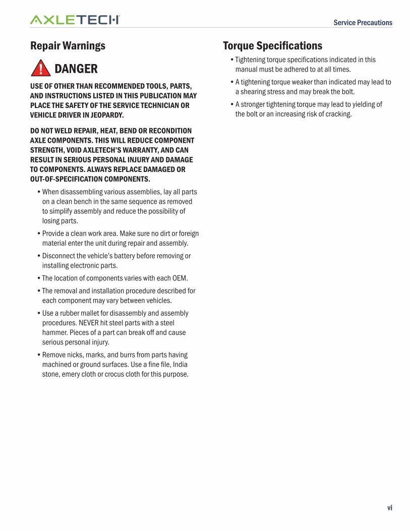
Repair Warnings
! DANGERUSE OF OTHER THAN RECOMMENDED TOOLS, PARTS, AND INSTRUCTIONS LISTED IN THIS PUBLICATION MAY PLACE THE SAFETY OF THE SERVICE TECHNICIAN OR VEHICLE DRIVER IN JEOPARDY.
DO NOT WELD REPAIR, HEAT, BEND OR RECONDITION AXLE COMPONENTS. THIS WILL REDUCE COMPONENT STRENGTH, VOID AXLETECH’S WARRANTY, AND CAN RESULT IN SERIOUS PERSONAL INJURY AND DAMAGE TO COMPONENTS. ALWAYS REPLACE DAMAGED OR OUT-OF-SPECIFICATION COMPONENTS.
• When disassembling various assemblies, lay all parts on a clean bench in the same sequence as removed to simplify assembly and reduce the possibility of losing parts.
• Provide a clean work area. Make sure no dirt or foreign material enter the unit during repair and assembly.
• Disconnect the vehicle’s battery before removing or installing electronic parts.
• The location of components varies with each OEM.
• The removal and installation procedure described for each component may vary between vehicles.
• Use a rubber mallet for disassembly and assembly procedures. NEVER hit steel parts with a steel hammer. Pieces of a part can break off and cause serious personal injury.
• Remove nicks, marks, and burrs from parts having machined or ground surfaces. Use a fi ne fi le, India stone, emery cloth or crocus cloth for this purpose.
Torque Specifi cations• Tightening torque specifi cations indicated in this
manual must be adhered to at all times.
• A tightening torque weaker than indicated may lead to a shearing stress and may break the bolt.
• A stronger tightening torque may lead to yielding of the bolt or an increasing risk of cracking.
Section 1: Introduction
1
Section 1: Introduction
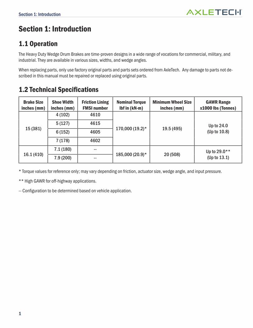
1.1 OperationThe Heavy Duty Wedge Drum Brakes are time-proven designs in a wide range of vocations for commercial, military, and industrial. They are available in various sizes, widths, and wedge angles.
When replacing parts, only use factory original parts and parts sets ordered from AxleTech. Any damage to parts not de-scribed in this manual must be repaired or replaced using original parts.
1.2 Technical Specifi cations
Brake Sizeinches (mm)
Shoe Widthinches (mm)
Friction LiningFMSI number
Nominal Torquelbf in (kN·m)
Minimum Wheel Sizeinches (mm)
GAWR Rangex1000 lbs (Tonnes)
15 (381)
4 (102) 4610
170,000 (19.2)* 19.5 (495) Up to 24.0(Up to 10.8)
5 (127) 4615
6 (152) 4605
7 (178) 4602
16.1 (410)7.1 (180) --
185,000 (20.9)* 20 (508) Up to 29.0**(Up to 13.1)7.9 (200) --
* Torque values for reference only; may vary depending on friction, actuator size, wedge angle, and input pressure.
** High GAWR for off -highway applications.
-- Confi guration to be determined based on vehicle application.
Section 1: Introduction
2
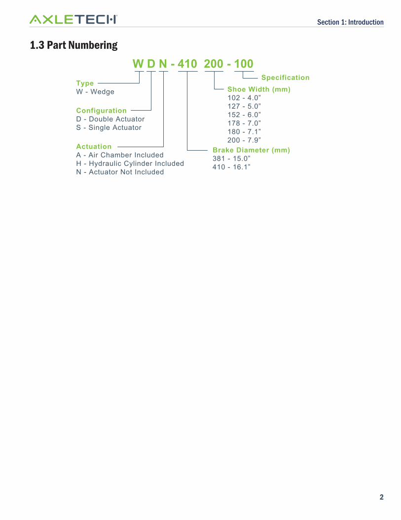
1.3 Part Numbering
W D N - 410 200 - 100TypeW - Wedge
ActuationA - Air Chamber IncludedH - Hydraulic Cylinder IncludedN - Actuator Not Included
ConfigurationD - Double ActuatorS - Single Actuator
Shoe Width (mm)102 - 4.0”127 - 5.0”152 - 6.0”178 - 7.0”180 - 7.1”200 - 7.9”
Brake Diameter (mm)381 - 15.0”410 - 16.1”
Specification
Section 1: Introduction
3
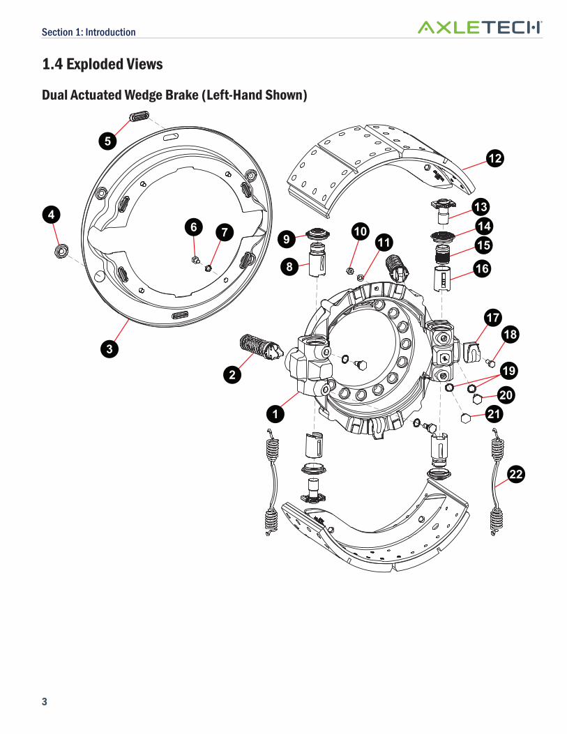
1.4 Exploded Views
Dual Actuated Wedge Brake (Left-Hand Shown)
1
2
4 13
22
6 7
3
1718
19
20
9
8
12
1415
16
1110
5
21
Section 1: Introduction
4
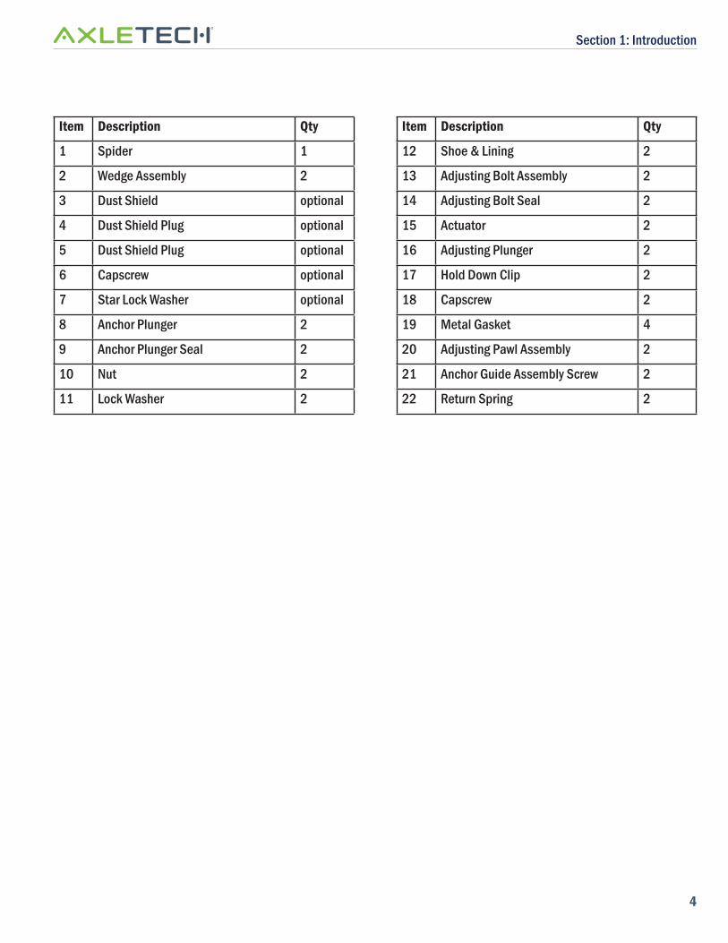
Item Description Qty
1 Spider 1
2 Wedge Assembly 2
3 Dust Shield optional
4 Dust Shield Plug optional
5 Dust Shield Plug optional
6 Capscrew optional
7 Star Lock Washer optional
8 Anchor Plunger 2
9 Anchor Plunger Seal 2
10 Nut 2
11 Lock Washer 2
Item Description Qty
12 Shoe & Lining 2
13 Adjusting Bolt Assembly 2
14 Adjusting Bolt Seal 2
15 Actuator 2
16 Adjusting Plunger 2
17 Hold Down Clip 2
18 Capscrew 2
19 Metal Gasket 4
20 Adjusting Pawl Assembly 2
21 Anchor Guide Assembly Screw 2
22 Return Spring 2
Section 1: Introduction
5
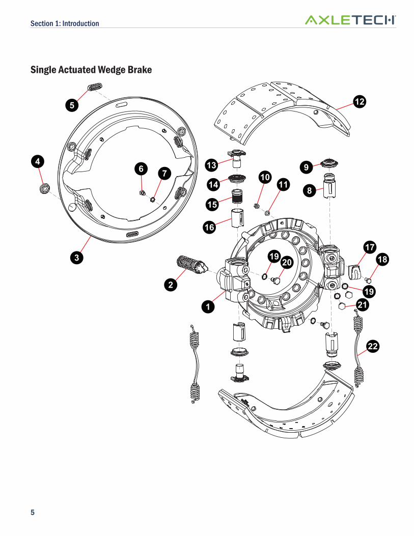
Single Actuated Wedge Brake
1
2
4 13
22
6 7
317
18
19
9
8
12
14
15
16
1110
5
21
19 20

Section 1: Introduction
6
Item Description Qty
1 Spider 1
2 Wedge Assembly 1
3 Dust Shield optional
4 Dust Shield Plug optional
5 Dust Shield Plug optional
6 Capscrew optional
7 Star Lock Washer optional
8 Anchor Plunger 2
9 Anchor Plunger Seal 2
10 Nut 2
11 Lock Washer 2
Item Description Qty
12 Shoe & Lining 2
13 Adjusting Bolt Assembly 2
14 Adjusting Bolt Seal 2
15 Actuator 2
16 Adjusting Plunger 2
17 Hold Down Clip 2
18 Capscrew 2
19 Metal Gasket 4
20 Adjusting Pawl Assembly 2
21 Anchor Guide Assembly Screw 2
22 Return Spring 2
Section 1: Introduction
7
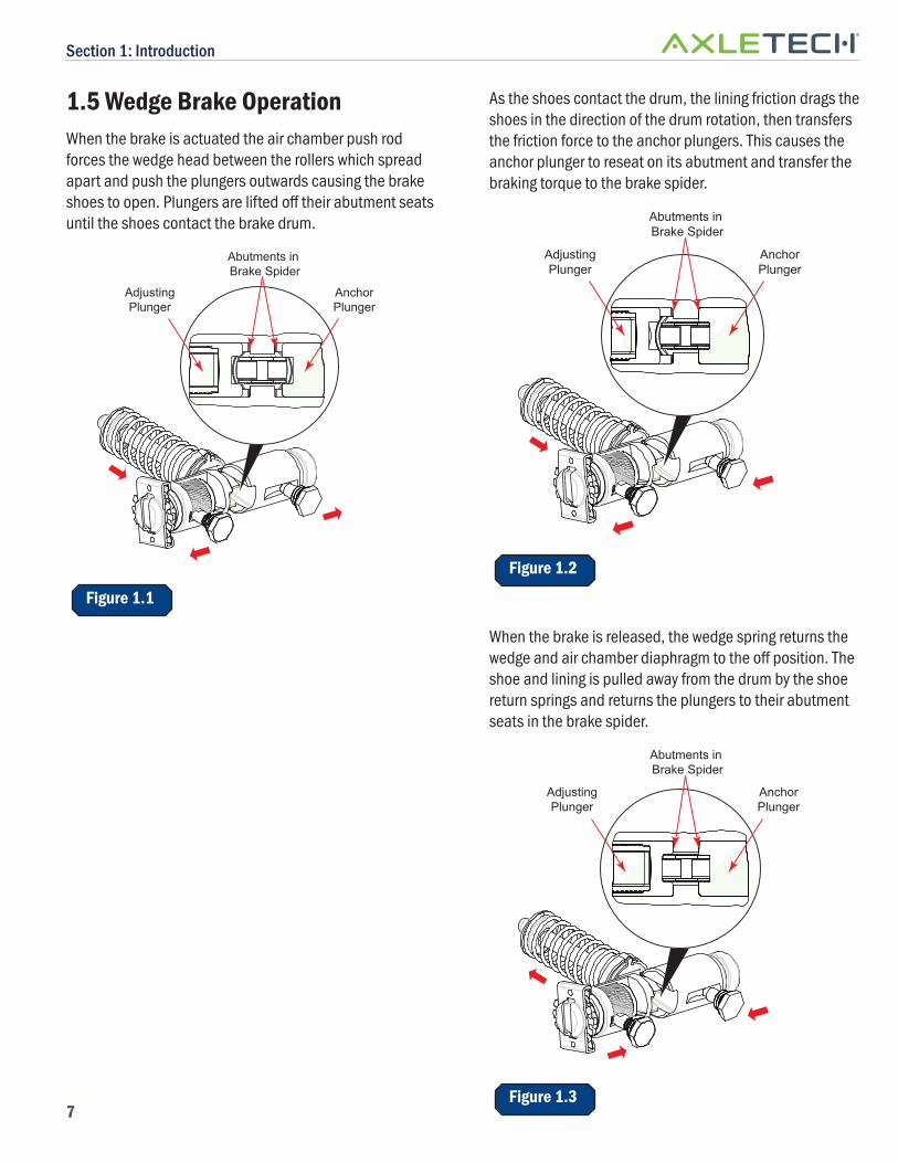
1.5 Wedge Brake OperationWhen the brake is actuated the air chamber push rod forces the wedge head between the rollers which spread apart and push the plungers outwards causing the brake shoes to open. Plungers are lifted off their abutment seats until the shoes contact the brake drum.
AdjustingPlunger
AnchorPlunger
Abutments in Brake Spider
Figure 1.1
As the shoes contact the drum, the lining friction drags the shoes in the direction of the drum rotation, then transfers the friction force to the anchor plungers. This causes the anchor plunger to reseat on its abutment and transfer the braking torque to the brake spider.
AdjustingPlunger
AnchorPlunger
Abutments in Brake Spider
Figure 1.2
When the brake is released, the wedge spring returns the wedge and air chamber diaphragm to the off position. The shoe and lining is pulled away from the drum by the shoe return springs and returns the plungers to their abutment seats in the brake spider.
AdjustingPlunger
AnchorPlunger
Abutments in Brake Spider
Figure 1.3
Section 1: Introduction
8
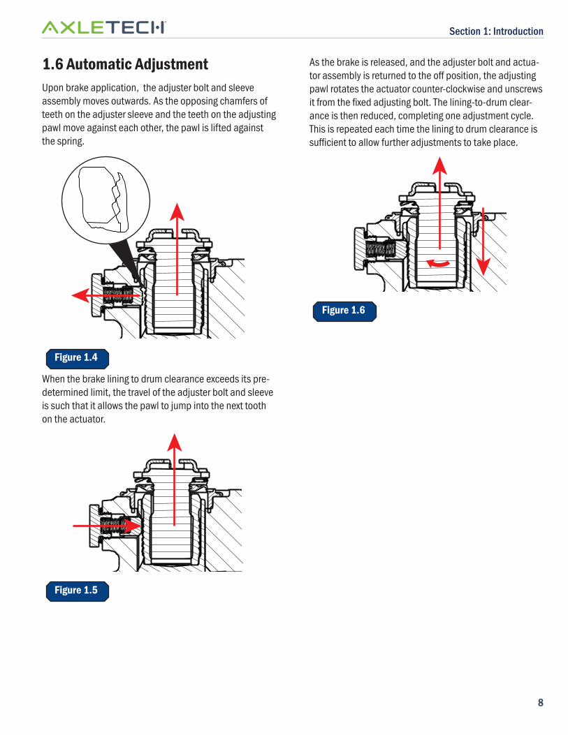
1.6 Automatic AdjustmentUpon brake application, the adjuster bolt and sleeve assembly moves outwards. As the opposing chamfers of teeth on the adjuster sleeve and the teeth on the adjusting pawl move against each other, the pawl is lifted against the spring.
Figure 1.4
When the brake lining to drum clearance exceeds its pre-determined limit, the travel of the adjuster bolt and sleeve is such that it allows the pawl to jump into the next tooth on the actuator.
Figure 1.5
As the brake is released, and the adjuster bolt and actua-tor assembly is returned to the off position, the adjusting pawl rotates the actuator counter-clockwise and unscrews it from the fi xed adjusting bolt. The lining-to-drum clear-ance is then reduced, completing one adjustment cycle. This is repeated each time the lining to drum clearance is suffi cient to allow further adjustments to take place.
Figure 1.6
Section 2: Disassembly
9
Section 2: Disassembly
! DANGERCHOCK AND JACK UP THE VEHICLE. THEN REMOVE THE WHEEL BEING WORKED ON. WHEN WORKING ON BRAKES, THE SPRING BRAKE CHAMBER MUST BE KEPT IN THE OFF POSITION BY MANUALLY CAGING THE SPRING (REFER TO MANUFACTURER’S INSTRUC-TIONS).
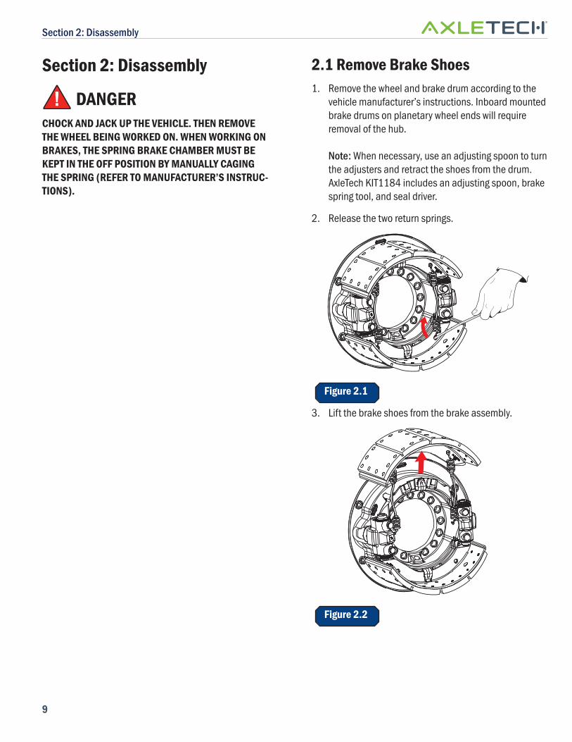
2.1 Remove Brake Shoes1. Remove the wheel and brake drum according to the
vehicle manufacturer’s instructions. Inboard mounted brake drums on planetary wheel ends will require removal of the hub.
Note: When necessary, use an adjusting spoon to turn the adjusters and retract the shoes from the drum. AxleTech KIT1184 includes an adjusting spoon, brake spring tool, and seal driver.
2. Release the two return springs.
Figure 2.1
3. Lift the brake shoes from the brake assembly.
Figure 2.2
Section 2: Disassembly
10
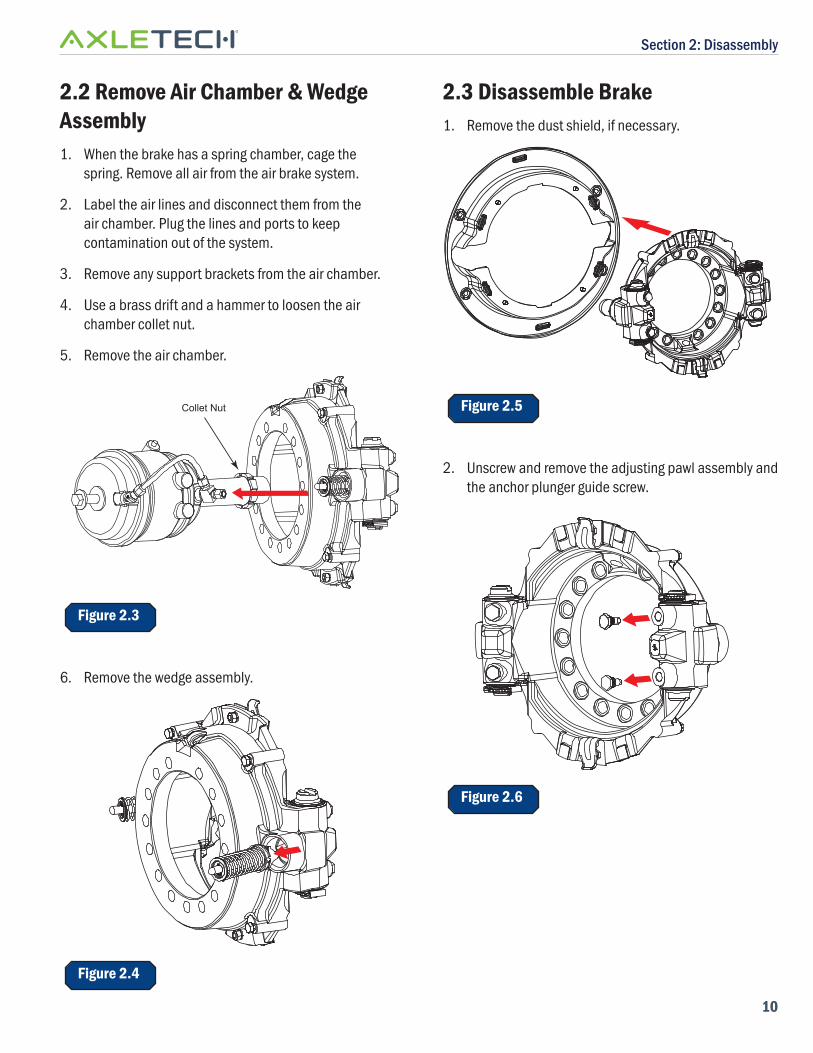
2.2 Remove Air Chamber & Wedge Assembly1. When the brake has a spring chamber, cage the
spring. Remove all air from the air brake system.
2. Label the air lines and disconnect them from the air chamber. Plug the lines and ports to keep contamination out of the system.
3. Remove any support brackets from the air chamber.
4. Use a brass drift and a hammer to loosen the air chamber collet nut.
5. Remove the air chamber.
Collet Nut
Figure 2.3
6. Remove the wedge assembly.
Figure 2.4
2.3 Disassemble Brake1. Remove the dust shield, if necessary.
Figure 2.5
2. Unscrew and remove the adjusting pawl assembly and the anchor plunger guide screw.
Figure 2.6
Section 2: Disassembly
11
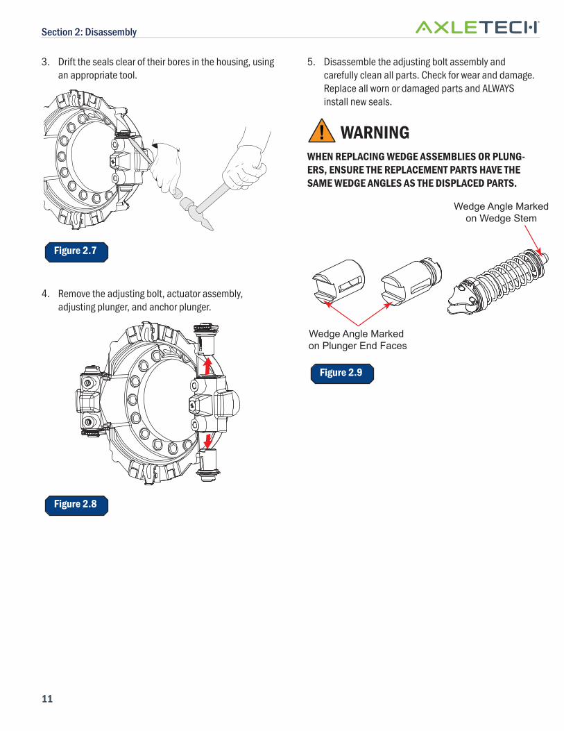
3. Drift the seals clear of their bores in the housing, using an appropriate tool.
Figure 2.7
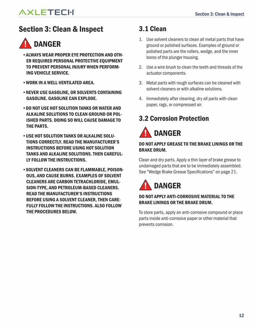
4. Remove the adjusting bolt, actuator assembly, adjusting plunger, and anchor plunger.
Figure 2.8
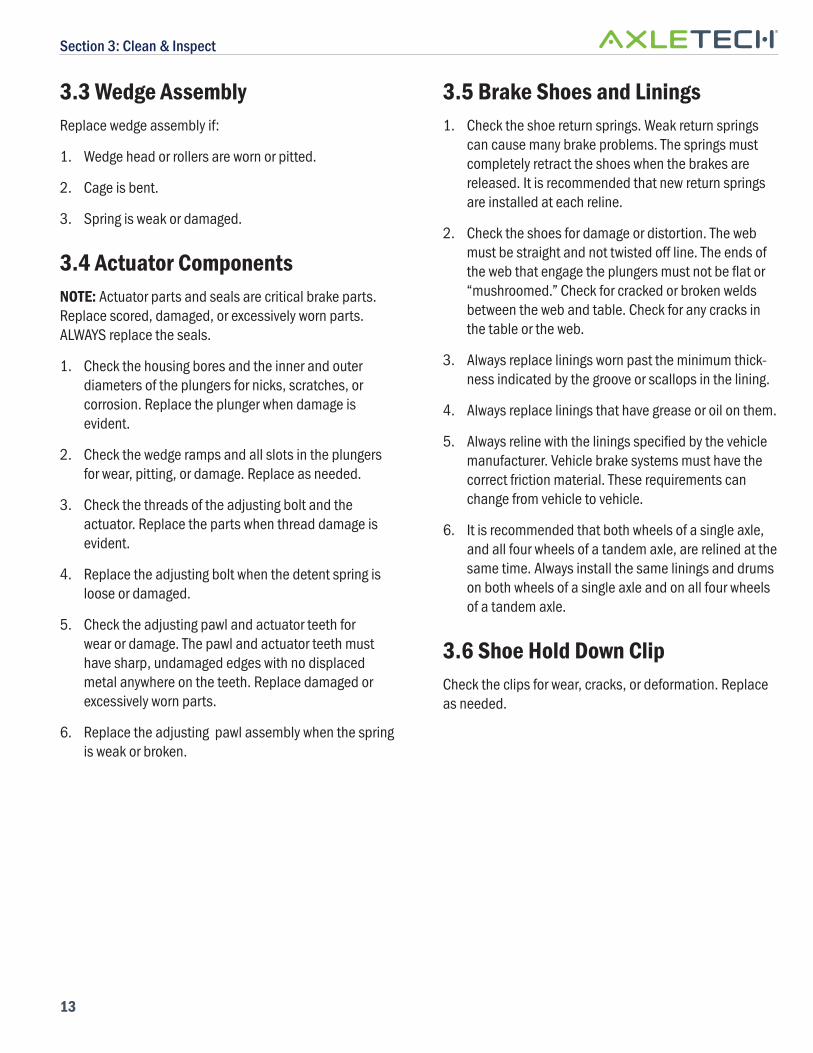
5. Disassemble the adjusting bolt assembly and carefully clean all parts. Check for wear and damage. Replace all worn or damaged parts and ALWAYS install new seals.
! WARNINGWHEN REPLACING WEDGE ASSEMBLIES OR PLUNG-ERS, ENSURE THE REPLACEMENT PARTS HAVE THE SAME WEDGE ANGLES AS THE DISPLACED PARTS.
Wedge Angle Markedon Wedge Stem
Wedge Angle Marked on Plunger End Faces
Figure 2.9
Section 3: Clean & Inspect
12
Section 3: Clean & Inspect
! DANGER•ALWAYS WEAR PROPER EYE PROTECTION AND OTH-
ER REQUIRED PERSONAL PROTECTIVE EQUIPMENT TO PREVENT PERSONAL INJURY WHEN PERFORM-ING VEHICLE SERVICE.
•WORK IN A WELL-VENTILATED AREA.
•NEVER USE GASOLINE, OR SOLVENTS CONTAINING GASOLINE. GASOLINE CAN EXPLODE.
•DO NOT USE HOT SOLUTION TANKS OR WATER AND ALKALINE SOLUTIONS TO CLEAN GROUND OR POL-ISHED PARTS. DOING SO WILL CAUSE DAMAGE TO THE PARTS.
•USE HOT SOLUTION TANKS OR ALKALINE SOLU-TIONS CORRECTLY. READ THE MANUFACTURER’S INSTRUCTIONS BEFORE USING HOT SOLUTION TANKS AND ALKALINE SOLUTIONS. THEN CAREFUL-LY FOLLOW THE INSTRUCTIONS.
•SOLVENT CLEANERS CAN BE FLAMMABLE, POISON-OUS, AND CAUSE BURNS. EXAMPLES OF SOLVENT CLEANERS ARE CARBON TETRACHLORIDE, EMUL-SION-TYPE, AND PETROLEUM-BASED CLEANERS. READ THE MANUFACTURER’S INSTRUCTIONS BEFORE USING A SOLVENT CLEANER, THEN CARE-FULLY FOLLOW THE INSTRUCTIONS. ALSO FOLLOW THE PROCEDURES BELOW.
3.1 Clean1. Use solvent cleaners to clean all metal parts that have
ground or polished surfaces. Examples of ground or polished parts are the rollers, wedge, and the inner bores of the plunger housing.
2. Use a wire brush to clean the teeth and threads of the actuator components.
3. Metal parts with rough surfaces can be cleaned with solvent cleaners or with alkaline solutions.
4. Immediately after cleaning, dry all parts with clean paper, rags, or compressed air.
3.2 Corrosion Protection
! DANGERDO NOT APPLY GREASE TO THE BRAKE LININGS OR THE BRAKE DRUM.
Clean and dry parts. Apply a thin layer of brake grease to undamaged parts that are to be immediately assembled. See “Wedge Brake Grease Specifi cations” on page 21.
! DANGERDO NOT APPLY ANTI-CORROSIVE MATERIAL TO THE BRAKE LININGS OR THE BRAKE DRUM.
To store parts, apply an anti-corrosive compound or place parts inside anti-corrosive paper or other material that prevents corrosion.
Section 3: Clean & Inspect
13
3.3 Wedge AssemblyReplace wedge assembly if:
1. Wedge head or rollers are worn or pitted.
2. Cage is bent.
3. Spring is weak or damaged.
3.4 Actuator ComponentsNOTE: Actuator parts and seals are critical brake parts. Replace scored, damaged, or excessively worn parts. ALWAYS replace the seals.
1. Check the housing bores and the inner and outer diameters of the plungers for nicks, scratches, or corrosion. Replace the plunger when damage is evident.
2. Check the wedge ramps and all slots in the plungers for wear, pitting, or damage. Replace as needed.
3. Check the threads of the adjusting bolt and the actuator. Replace the parts when thread damage is evident.
4. Replace the adjusting bolt when the detent spring is loose or damaged.
5. Check the adjusting pawl and actuator teeth for wear or damage. The pawl and actuator teeth must have sharp, undamaged edges with no displaced metal anywhere on the teeth. Replace damaged or excessively worn parts.
6. Replace the adjusting pawl assembly when the spring is weak or broken.
3.5 Brake Shoes and Linings1. Check the shoe return springs. Weak return springs
can cause many brake problems. The springs must completely retract the shoes when the brakes are released. It is recommended that new return springs are installed at each reline.
2. Check the shoes for damage or distortion. The web must be straight and not twisted off line. The ends of the web that engage the plungers must not be fl at or “mushroomed.” Check for cracked or broken welds between the web and table. Check for any cracks in the table or the web.
3. Always replace linings worn past the minimum thick-ness indicated by the groove or scallops in the lining.
4. Always replace linings that have grease or oil on them.
5. Always reline with the linings specifi ed by the vehicle manufacturer. Vehicle brake systems must have the correct friction material. These requirements can change from vehicle to vehicle.
6. It is recommended that both wheels of a single axle, and all four wheels of a tandem axle, are relined at the same time. Always install the same linings and drums on both wheels of a single axle and on all four wheels of a tandem axle.
3.6 Shoe Hold Down ClipCheck the clips for wear, cracks, or deformation. Replace as needed.
Section 4: Assembly
14
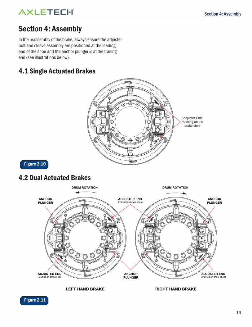
Section 4: AssemblyIn the reassembly of the brake, always ensure the adjusterbolt and sleeve assembly are positioned at the leading end of the shoe and the anchor plunger is at the trailing end (see illustrations below).
4.1 Single Actuated Brakes
Figure 2.10
“Adjuster End”marking on the
brake shoe
4.2 Dual Actuated BrakesDRUM ROTATION
ADJUSTER END(marked on brake shoe)
DRUM ROTATION
ANCHORPLUNGER
RIGHT HAND BRAKELEFT HAND BRAKE
ANCHORPLUNGER
ANCHORPLUNGER
ADJUSTER END(marked on brake shoe)
ADJUSTER END(marked on brake shoe)
Figure 2.11
Section 4: Assembly
15
4.3 Lubrication
! DANGERUSE OF NON-ORIGINAL PARTS COULD SERIOUSLY AFFECT BRAKE PERFORMANCE. ONLY ORIGINAL AXLETECH SPARE PARTS SHOULD BE USED.
BREATHING THE DUST GENERATED BY FRICTION OF BRAKE LININGS AGAINST DRUM IS HAZARDOUS. ALWAYS WEAR THE ASSIGNED PROTECTIVE EQUIPMENT WHEN SERVICING BRAKE UNITS AND AVOID REMAINING IN THE AREA UNLESS IT IS NECESSARY.
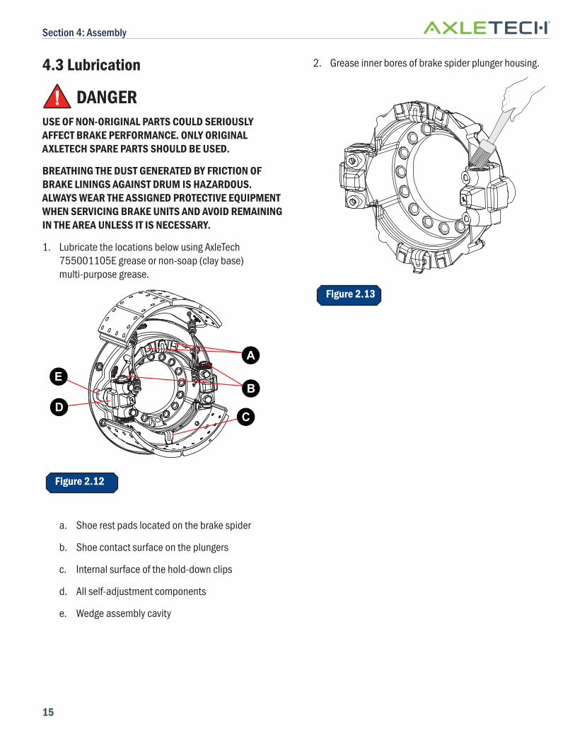
1. Lubricate the locations below using AxleTech 755001105E grease or non-soap (clay base) multi-purpose grease.
D
EB
C
A
Figure 2.12
a. Shoe rest pads located on the brake spider
b. Shoe contact surface on the plungers
c. Internal surface of the hold-down clips
d. All self-adjustment components
e. Wedge assembly cavity
2. Grease inner bores of brake spider plunger housing.
Figure 2.13
Section 4: Assembly
16
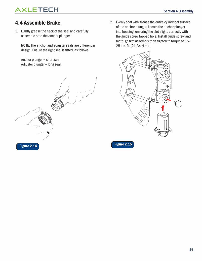
4.4 Assemble Brake1. Lightly grease the neck of the seal and carefully
assemble onto the anchor plunger.
NOTE: The anchor and adjuster seals are diff erent in design. Ensure the right seal is fi tted, as follows:
Anchor plunger = short sealAdjuster plunger = long seal
Figure 2.14
2. Evenly coat with grease the entire cylindrical surface of the anchor plunger. Locate the anchor plunger into housing, ensuring the slot aligns correctly with the guide screw tapped hole. Install guide screw and metal gasket assembly then tighten to torque to 15-25 lbs. ft. (21-34 N·m).
Figure 2.15
Section 4: Assembly
17
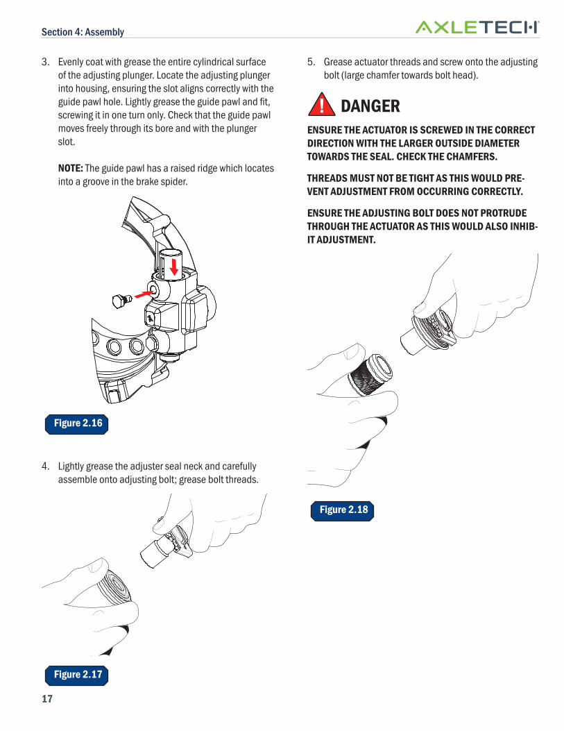
3. Evenly coat with grease the entire cylindrical surface of the adjusting plunger. Locate the adjusting plunger into housing, ensuring the slot aligns correctly with the guide pawl hole. Lightly grease the guide pawl and fi t, screwing it in one turn only. Check that the guide pawl moves freely through its bore and with the plunger slot.
NOTE: The guide pawl has a raised ridge which locates into a groove in the brake spider.
Figure 2.16
4. Lightly grease the adjuster seal neck and carefully assemble onto adjusting bolt; grease bolt threads.
Figure 2.17
5. Grease actuator threads and screw onto the adjusting bolt (large chamfer towards bolt head).
! DANGERENSURE THE ACTUATOR IS SCREWED IN THE CORRECT DIRECTION WITH THE LARGER OUTSIDE DIAMETER TOWARDS THE SEAL. CHECK THE CHAMFERS.
THREADS MUST NOT BE TIGHT AS THIS WOULD PRE-VENT ADJUSTMENT FROM OCCURRING CORRECTLY.
ENSURE THE ADJUSTING BOLT DOES NOT PROTRUDE THROUGH THE ACTUATOR AS THIS WOULD ALSO INHIB-IT ADJUSTMENT.
Figure 2.18
Section 4: Assembly
18
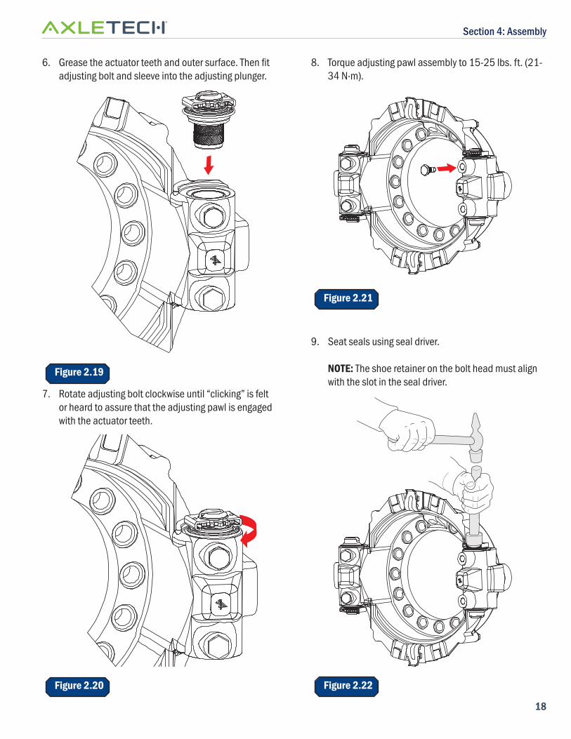
6. Grease the actuator teeth and outer surface. Then fi t adjusting bolt and sleeve into the adjusting plunger.
Figure 2.19
7. Rotate adjusting bolt clockwise until “clicking” is felt or heard to assure that the adjusting pawl is engaged with the actuator teeth.
Figure 2.20
8. Torque adjusting pawl assembly to 15-25 lbs. ft. (21-34 N·m).
Figure 2.21
9. Seat seals using seal driver.
NOTE: The shoe retainer on the bolt head must align with the slot in the seal driver.
Figure 2.22
Section 4: Assembly
19
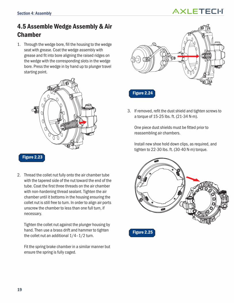
4.5 Assemble Wedge Assembly & Air Chamber1. Through the wedge bore, fi ll the housing to the wedge
seat with grease. Coat the wedge assembly with grease and fi t into bore aligning the raised ridges on the wedge with the corresponding slots in the wedge bore. Press the wedge in by hand up to plunger travel starting point.
Figure 2.23
2. Thread the collet nut fully onto the air chamber tube with the tapered side of the nut toward the end of the tube. Coat the fi rst three threads on the air chamber with non-hardening thread sealant. Tighten the air chamber until it bottoms in the housing ensuring the collet nut is still free to turn. In order to align air ports unscrew the chamber to less than one full turn, if necessary.
Tighten the collet nut against the plunger housing by hand. Then use a brass drift and hammer to tighten the collet nut an additional 1/4–1/2 turn.
Fit the spring brake chamber in a similar manner but ensure the spring is fully caged.
Figure 2.24
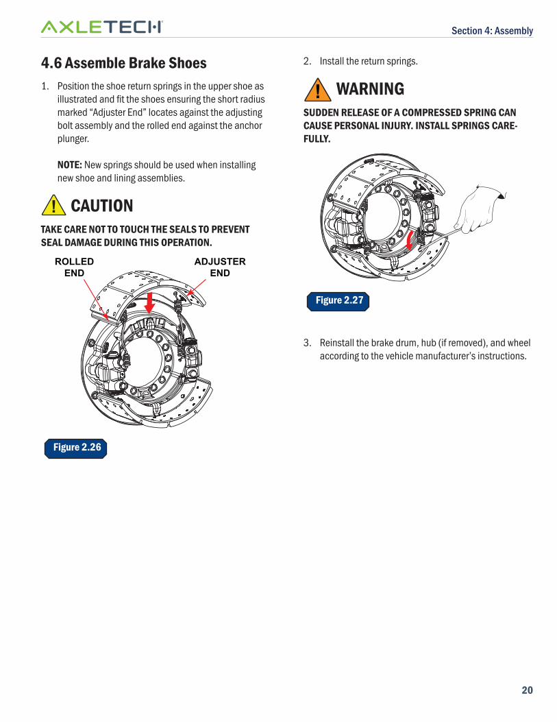
3. If removed, refi t the dust shield and tighten screws to a torque of 15-25 lbs. ft. (21-34 N·m).
One piece dust shields must be fi tted prior to reassembling air chambers.
Install new shoe hold down clips, as required, and tighten to 22-30 lbs. ft. (30-40 N·m) torque.
Figure 2.25
Section 4: Assembly
20
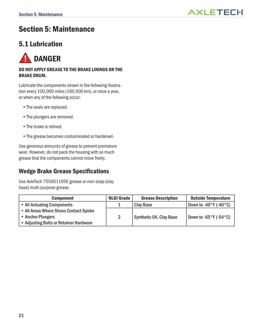
4.6 Assemble Brake Shoes1. Position the shoe return springs in the upper shoe as
illustrated and fi t the shoes ensuring the short radius marked “Adjuster End” locates against the adjusting bolt assembly and the rolled end against the anchor plunger.
NOTE: New springs should be used when installing new shoe and lining assemblies.
! CAUTIONTAKE CARE NOT TO TOUCH THE SEALS TO PREVENT SEAL DAMAGE DURING THIS OPERATION.
ADJUSTEREND
ROLLEDEND
Figure 2.26
2. Install the return springs.
! WARNINGSUDDEN RELEASE OF A COMPRESSED SPRING CAN CAUSE PERSONAL INJURY. INSTALL SPRINGS CARE-FULLY.
Figure 2.27
3. Reinstall the brake drum, hub (if removed), and wheel according to the vehicle manufacturer’s instructions.
Section 5: Maintenance
21
Section 5: Maintenance
5.1 Lubrication
! DANGERDO NOT APPLY GREASE TO THE BRAKE LININGS OR THE BRAKE DRUM.
Lubricate the components shown in the following illustra-tion every 100,000 miles (160,000 km), or once a year, or when any of the following occur:
• The seals are replaced.
• The plungers are removed.
• The brake is relined.
• The grease becomes contaminated or hardened.
Use generous amounts of grease to prevent premature wear. However, do not pack the housing with so much grease that the components cannot move freely.
Wedge Brake Grease Specifi cationsUse AxleTech 755001105E grease or non-soap (clay base) multi-purpose grease.
Component NLGI Grade Grease Description Outside Temperature• All Actuating Components• All Areas Where Shoes Contact Spider• Anchor Plungers• Adjusting Bolts or Retainer Hardware
1 Clay Base Down to -40°F (-40°C)
2 Synthetic Oil, Clay Base Down to -65°F (-54°C)
Section 5: Maintenance
22
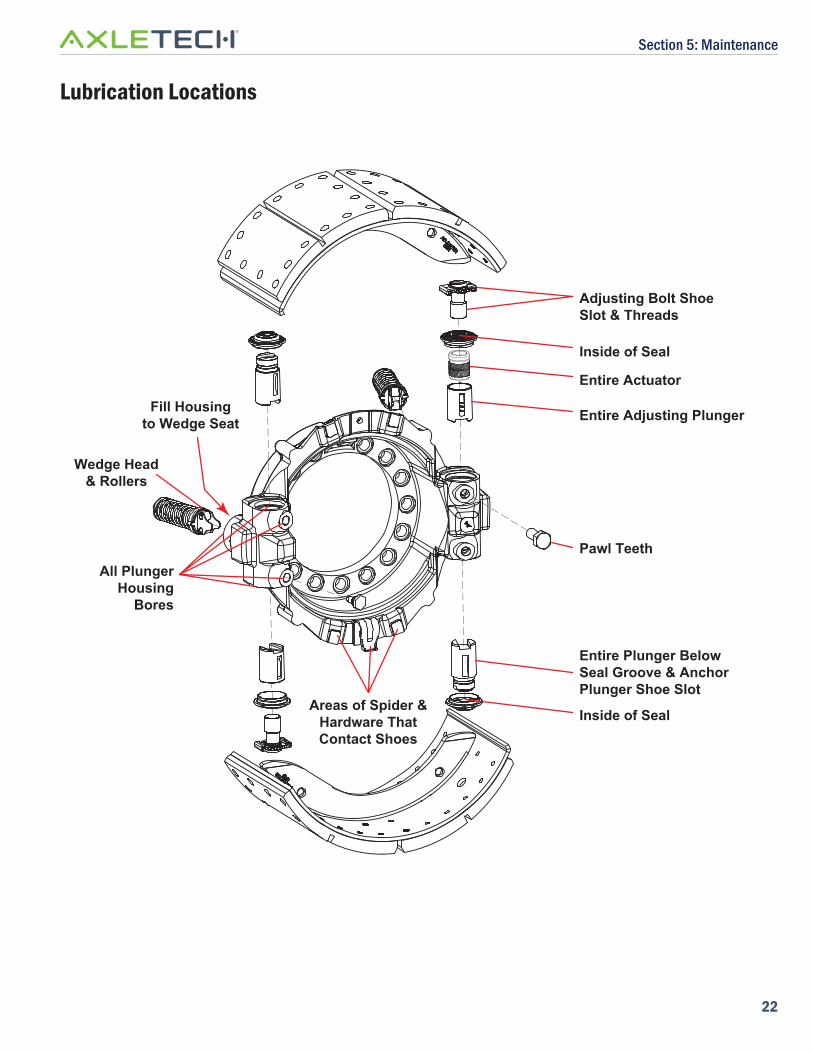
Lubrication Locations
Adjusting Bolt ShoeSlot & Threads
Inside of Seal
Entire Actuator
Entire Adjusting Plunger
Pawl TeethAll Plunger
HousingBores
Wedge Head& Rollers
Inside of Seal
Entire Plunger BelowSeal Groove & AnchorPlunger Shoe Slot
Areas of Spider &Hardware ThatContact Shoes
Fill Housingto Wedge Seat
Section 5: Maintenance
23
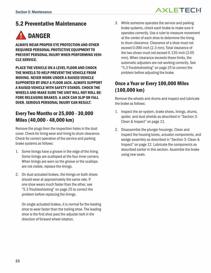
5.2 Preventative Maintenance
! DANGERALWAYS WEAR PROPER EYE PROTECTION AND OTHER REQUIRED PERSONAL PROTECTIVE EQUIPMENT TO PREVENT PERSONAL INJURY WHEN PERFORMING VEHI-CLE SERVICE.
PLACE THE VEHICLE ON A LEVEL FLOOR AND CHOCK THE WHEELS TO HELP PREVENT THE VEHICLE FROM MOVING. NEVER WORK UNDER A RAISED VEHICLE SUPPORTED BY ONLY A FLOOR JACK. ALWAYS SUPPORT A RAISED VEHICLE WITH SAFETY STANDS. CHOCK THE WHEELS AND MAKE SURE THE UNIT WILL NOT ROLL BE-FORE RELEASING BRAKES. A JACK CAN SLIP OR FALL OVER. SERIOUS PERSONAL INJURY CAN RESULT.
Every Two Months or 25,000 - 30,000 Miles (40,000 - 48,000 km)Remove the plugs from the inspection holes in the dust cover. Check for lining wear and lining to drum clearance. Check for correct operation of the service and parking brake systems as follows:
1. Some linings have a groove in the edge of the lining. Some linings are scalloped at the four inner corners. When linings are worn so the groove or the scallops are not visible, replace the linings.
2. On dual actuated brakes, the linings on both shoes should wear at approximately the same rate. If one shoe wears much faster than the other, see “5.3 Troubleshooting” on page 25 to correct the problem before replacing the linings.
On single actuated brakes, it is normal for the leading shoe to wear faster than the trailing shoe. The leading shoe is the fi rst shoe past the adjuster bolt in the direction of forward wheel rotation.
3. While someone operates the service and parking brake systems, check each brake to make sure it operates correctly. Use a ruler to measure movement at the center of each shoe to determine the lining to drum clearance. Clearance of a shoe must not exceed 0.090-inch (2.3 mm). Total clearance of the two shoes must not exceed 0.120-inch (3.05 mm). When clearance exceeds these limits, the automatic adjusters are not working correctly. See “5.3 Troubleshooting” on page 25 to correct the problem before adjusting the brake.
Once a Year or Every 100,000 Miles (160,000 km)Remove the wheels and drums and inspect and lubricate the brake as follows:
1. Inspect the air system, brake shoes, linings, drums, spider, and dust shields as described in “Section 3: Clean & Inspect” on page 12.
2. Disassemble the plunger housings. Clean and inspect the housing bores, actuator components, and wedge assembly as described in “Section 3: Clean & Inspect” on page 12. Lubricate the components as described earlier in this section. Assemble the brake using new seals.
Section 5: Maintenance
24
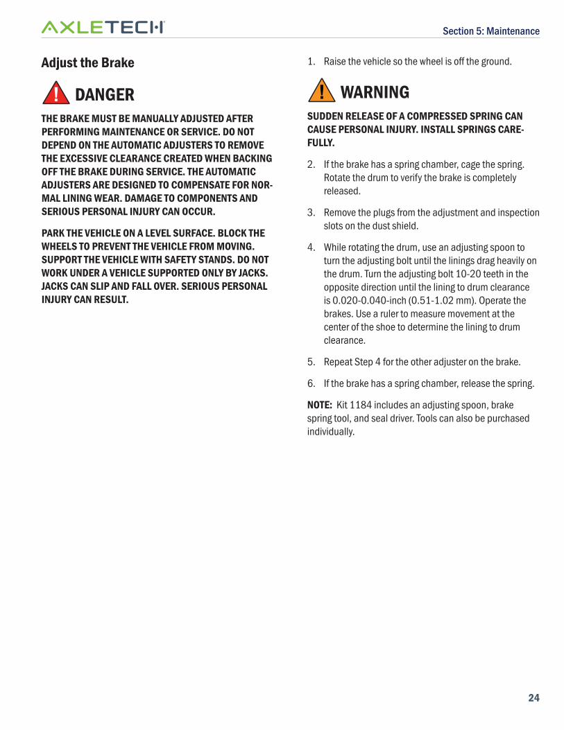
Adjust the Brake
! DANGERTHE BRAKE MUST BE MANUALLY ADJUSTED AFTER PERFORMING MAINTENANCE OR SERVICE. DO NOT DEPEND ON THE AUTOMATIC ADJUSTERS TO REMOVE THE EXCESSIVE CLEARANCE CREATED WHEN BACKING OFF THE BRAKE DURING SERVICE. THE AUTOMATIC ADJUSTERS ARE DESIGNED TO COMPENSATE FOR NOR-MAL LINING WEAR. DAMAGE TO COMPONENTS AND SERIOUS PERSONAL INJURY CAN OCCUR.
PARK THE VEHICLE ON A LEVEL SURFACE. BLOCK THE WHEELS TO PREVENT THE VEHICLE FROM MOVING. SUPPORT THE VEHICLE WITH SAFETY STANDS. DO NOT WORK UNDER A VEHICLE SUPPORTED ONLY BY JACKS. JACKS CAN SLIP AND FALL OVER. SERIOUS PERSONAL INJURY CAN RESULT.
1. Raise the vehicle so the wheel is off the ground.
! WARNINGSUDDEN RELEASE OF A COMPRESSED SPRING CAN CAUSE PERSONAL INJURY. INSTALL SPRINGS CARE-FULLY.
2. If the brake has a spring chamber, cage the spring. Rotate the drum to verify the brake is completely released.
3. Remove the plugs from the adjustment and inspection slots on the dust shield.
4. While rotating the drum, use an adjusting spoon to turn the adjusting bolt until the linings drag heavily on the drum. Turn the adjusting bolt 10-20 teeth in the opposite direction until the lining to drum clearance is 0.020-0.040-inch (0.51-1.02 mm). Operate the brakes. Use a ruler to measure movement at the center of the shoe to determine the lining to drum clearance.
5. Repeat Step 4 for the other adjuster on the brake.
6. If the brake has a spring chamber, release the spring.
NOTE: Kit 1184 includes an adjusting spoon, brake spring tool, and seal driver. Tools can also be purchased individually.
Section 5: Maintenance
25
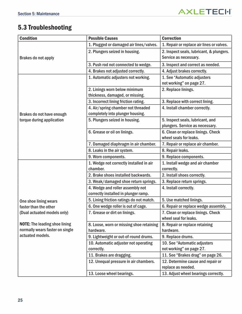
5.3 TroubleshootingCondition Possible Causes Correction
Brakes do not apply
1. Plugged or damaged air lines/valves. 1. Repair or replace air lines or valves.2. Plungers seized in housing. 2. Inspect seals, lubricant, & plungers.
Service as necessary.
3. Push rod not connected to wedge. 3. Inspect and correct as needed.4. Brakes not adjusted correctly. 4. Adjust brakes correctly.
Brakes do not have enough torque during application
1. Automatic adjusters not working. 1. See “Automatic adjusters not working” on page 27.
2. Linings worn below minimum thickness, damaged, or missing.
2. Replace linings.
3. Incorrect lining friction rating. 3. Replace with correct lining.4. Air/spring chamber not threaded completely into plunger housing.
4. Install chamber correctly.
5. Plungers seized in housing. 5. Inspect seals, lubricant, and plungers. Service as necessary.
6. Grease or oil on linings. 6. Clean or replace linings. Check wheel seals for leaks.
7. Damaged diaphragm in air chamber. 7. Repair or replace air chamber.8. Leaks in the air system. 8. Repair leaks.9. Worn components. 9. Replace components.
One shoe lining wears faster than the other (Dual actuated models only)
NOTE: The leading shoe lining normally wears faster on single actuated models.
1. Wedge not correctly installed in air chamber.
1. Install wedge and air chamber correctly.
2. Brake shoes installed backwards. 2. Install shoes correctly.3. Weak/damaged shoe return springs. 3. Replace return springs.4. Wedge and roller assembly not correctly installed in plunger ramp.
4. Install correctly.
5. Lining friction ratings do not match. 5. Use matched linings.6. One wedge roller is out of cage. 6. Repair or replace wedge assembly.7. Grease or dirt on linings. 7. Clean or replace linings. Check
wheel seal for leaks.8. Loose, worn or missing shoe retaining hardware.
8. Repair or replace retaining hardware.
9. Lightweight or out-of-round drums. 9. Replace drums.10. Automatic adjuster not operating correctly.
10. See “Automatic adjusters not working” on page 27.
11. Brakes are dragging. 11. See “Brakes drag” on page 26.12. Unequal pressure in air chambers. 12. Determine cause and repair or
replace as needed.13. Loose wheel bearings. 13. Adjust wheel bearings correctly.
Section 5: Maintenance
26
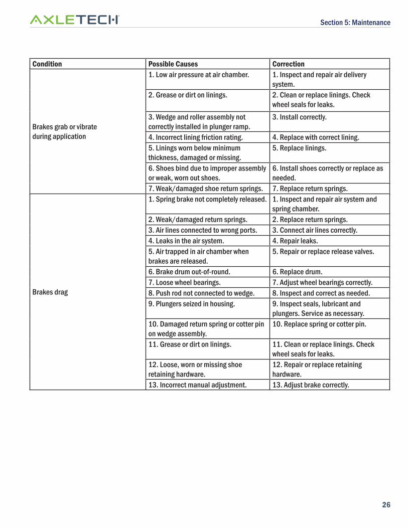
Condition Possible Causes Correction
Brakes grab or vibrate during application
1. Low air pressure at air chamber. 1. Inspect and repair air delivery system.
2. Grease or dirt on linings. 2. Clean or replace linings. Check wheel seals for leaks.
3. Wedge and roller assembly not correctly installed in plunger ramp.
3. Install correctly.
4. Incorrect lining friction rating. 4. Replace with correct lining.5. Linings worn below minimum thickness, damaged or missing.
5. Replace linings.
6. Shoes bind due to improper assembly or weak, worn out shoes.
6. Install shoes correctly or replace as needed.
7. Weak/damaged shoe return springs. 7. Replace return springs.
Brakes drag
1. Spring brake not completely released. 1. Inspect and repair air system and spring chamber.
2. Weak/damaged return springs. 2. Replace return springs.3. Air lines connected to wrong ports. 3. Connect air lines correctly. 4. Leaks in the air system. 4. Repair leaks.5. Air trapped in air chamber when brakes are released.
5. Repair or replace release valves.
6. Brake drum out-of-round. 6. Replace drum.7. Loose wheel bearings. 7. Adjust wheel bearings correctly.8. Push rod not connected to wedge. 8. Inspect and correct as needed.9. Plungers seized in housing. 9. Inspect seals, lubricant and
plungers. Service as necessary.10. Damaged return spring or cotter pin on wedge assembly.
10. Replace spring or cotter pin.
11. Grease or dirt on linings. 11. Clean or replace linings. Check wheel seals for leaks.
12. Loose, worn or missing shoe retaining hardware.
12. Repair or replace retaining hardware.
13. Incorrect manual adjustment. 13. Adjust brake correctly.
Section 5: Maintenance
27
Condition Possible Causes Correction
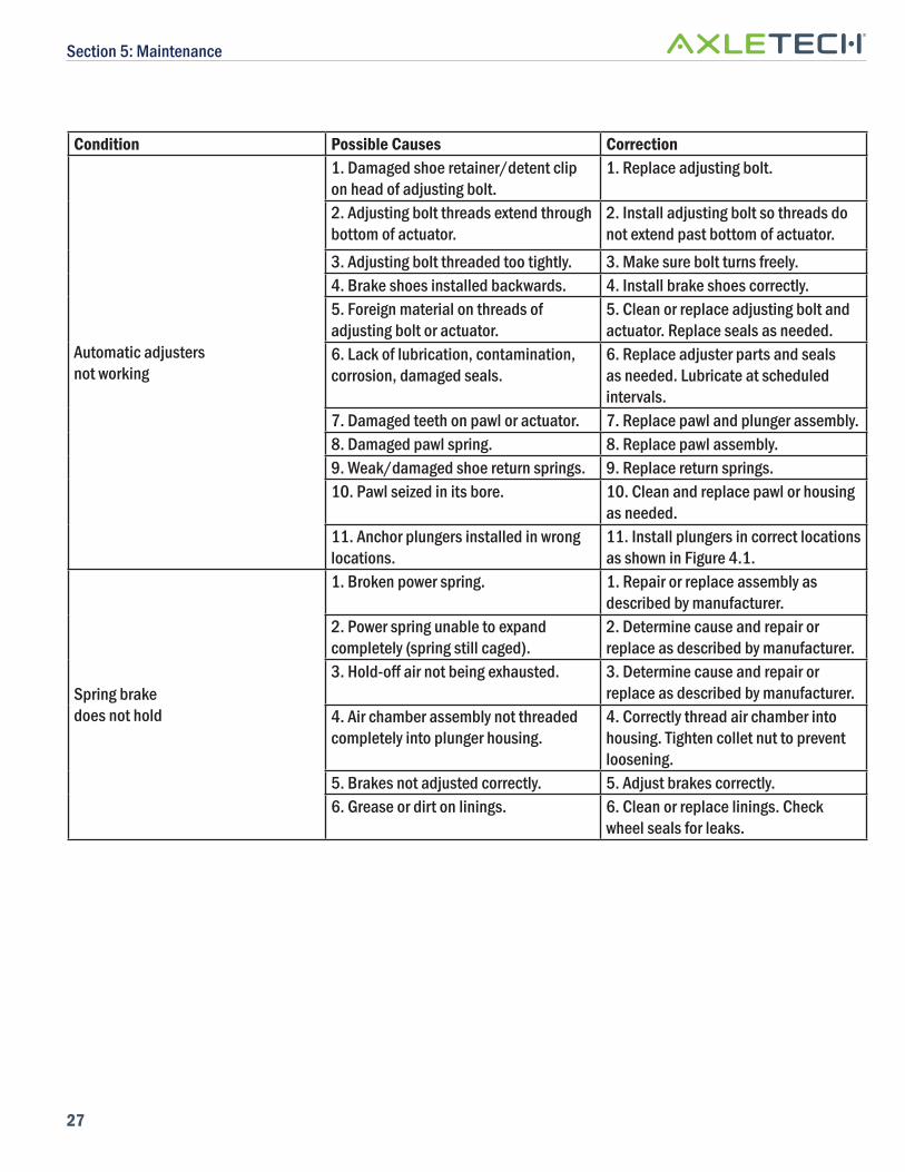
Automatic adjusters not working
1. Damaged shoe retainer/detent clip on head of adjusting bolt.
1. Replace adjusting bolt.
2. Adjusting bolt threads extend through bottom of actuator.
2. Install adjusting bolt so threads do not extend past bottom of actuator.
3. Adjusting bolt threaded too tightly. 3. Make sure bolt turns freely. 4. Brake shoes installed backwards. 4. Install brake shoes correctly. 5. Foreign material on threads of adjusting bolt or actuator.
5. Clean or replace adjusting bolt and actuator. Replace seals as needed.
6. Lack of lubrication, contamination, corrosion, damaged seals.
6. Replace adjuster parts and seals as needed. Lubricate at scheduled intervals.
7. Damaged teeth on pawl or actuator. 7. Replace pawl and plunger assembly. 8. Damaged pawl spring. 8. Replace pawl assembly. 9. Weak/damaged shoe return springs. 9. Replace return springs. 10. Pawl seized in its bore. 10. Clean and replace pawl or housing
as needed. 11. Anchor plungers installed in wrong locations.
11. Install plungers in correct locations as shown in Figure 4.1.
Spring brake does not hold
1. Broken power spring. 1. Repair or replace assembly as described by manufacturer.
2. Power spring unable to expand completely (spring still caged).
2. Determine cause and repair or replace as described by manufacturer.
3. Hold-off air not being exhausted. 3. Determine cause and repair or replace as described by manufacturer.
4. Air chamber assembly not threaded completely into plunger housing.
4. Correctly thread air chamber into housing. Tighten collet nut to prevent loosening.
5. Brakes not adjusted correctly. 5. Adjust brakes correctly. 6. Grease or dirt on linings. 6. Clean or replace linings. Check
wheel seals for leaks.
Appendix
28
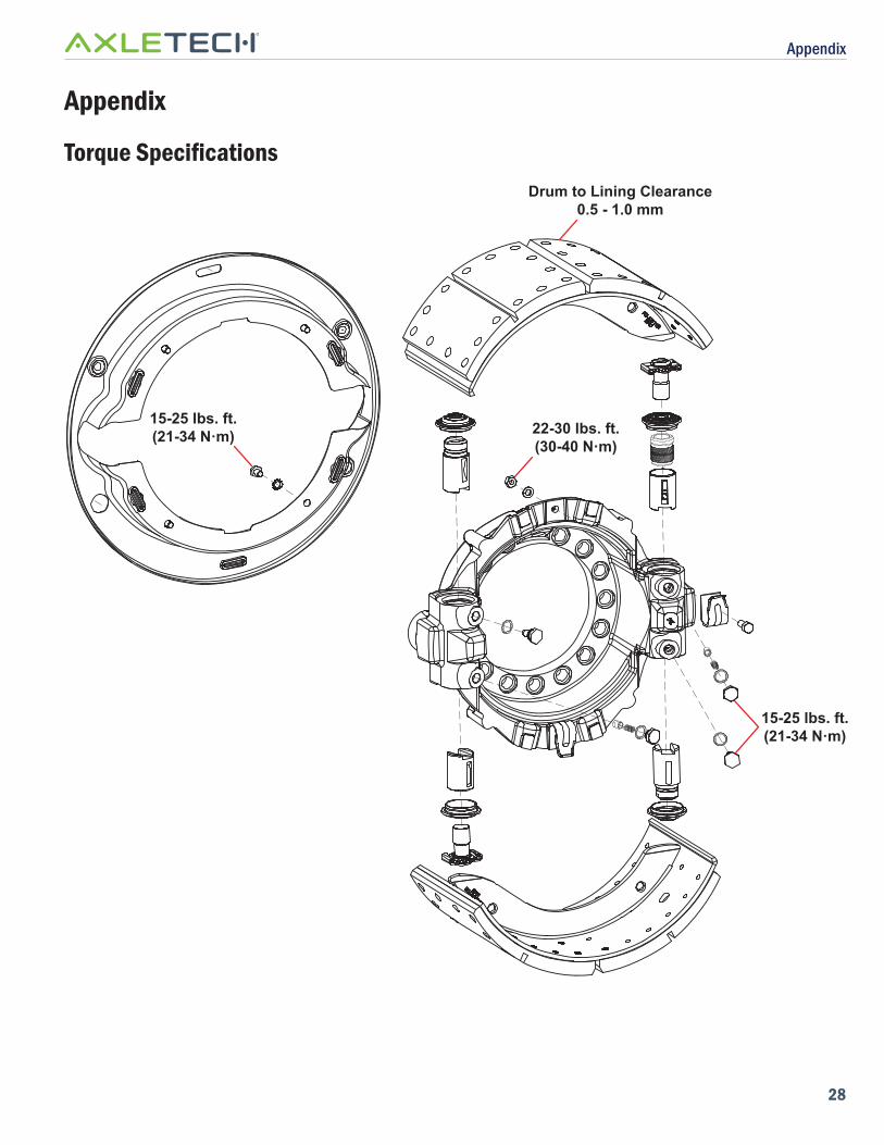
Appendix
Torque Specifi cations
22-30 lbs. ft.(30-40 N·m)
15-25 lbs. ft.(21-34 N·m)
Drum to Lining Clearance0.5 - 1.0 mm
15-25 lbs. ft.(21-34 N·m)

© 2018 AxleTech International LLC. All rights reserved. AxleTech and AxleTech International are registered trademarks of AxleTech International LLC. All other brands and product names are trademarks or registered trademarks of their respective owners. Information supplied by AxleTech is believed to be accurate and reliable. AxleTech reserves the right, without notice, to makes changes in product design or specifications.
Customer Service 877-547-3907+33 (0) 4 77 92 88 92
Customer Service Fax 877-547-3987
Email OE: [email protected]: [email protected]
www.axletech.com
BSM-0381E 09/18