Embed Size (px)
Citation preview
788 J SCI IND RES VOL 67 OCTOBER 2008Journal of Scientific & Industrial ResearchVol. 67, October 2008, pp.788-796
*Author for correspondenceTel.: +90 346 2191339; Fax: +90 346 219 11 75E-mail: [email protected]
Wedge type vaned diffuser flow measurements in a low speedcentrifugal compressor
Ümit Nazl1 Temel, Adnan Öztürk and Ali Pinarbasi*
Department of Mechanical Engineering, Engineering Faculty, Cumhuriyet University, 58140, Sivas, Turkey
Received 10 March 2008; revised 19 June 2008; accepted 26 June 2008
This study establishes effectiveness of vaned diffuser in comparison with vaneless diffusers in centrifugal compressor.Hot wire measurements at three inter-vane positions for mean velocity, turbulent kinetic energy and flow angle distributions invaneless space and vane region of a low speed centrifugal compressor are presented. A low speed compressor with a 19 bladedbackswept impeller and 16-wedge vanes diffuser was used. The flow entering diffuser closely resembles classic jet-wake flowcharacteristic of centrifugal impeller discharges. A strong upstream influence of diffuser vanes, which resulted in significantvariations in flow quantities between vane-to-vane locations, was observed. Circumferential variations due to passage andblade wakes rapidly mixed out in vaneless space, although some variations were still discernible in vaned region. Impellerblade wakes mixed out rapidly within vaneless space than in an equivalent vaneless diffuser. Although, flow is highly non-uniform in velocity at impeller exit, there was no any separation from diffuser vanes. Presence of vanes accelerated mixing outprocess. Therefore, use of twisted vanes in diffuser would be beneficial in reducing losses.
Keywords: Compressor, Diffuser flow, Vaned diffuser
Introduction
Vaned diffusers are used in wide variety of compressorapplications. Yoshinaga et al1 used vaned diffusers toimprove stage efficiency (4%) in comparison withvaneless diffuser for same diffuser outlet radius. Inoue &Cumpsty2 observed that circumferentially averagedmean radial velocity profile in axial direction for vaneddiffuser inlet was almost identical with that for vanelessdiffuser. Krain3 observed that in a flat straight channeldiffuser with a splitter blade impeller an unsteady flowin vaned diffuser entrance region was highly distorted.These studies indicate that flow is highly distorted nearleading edge of vane. This study presents measurement ofdetailed flow in a vaned diffuser in comparison withvaneless diffuser used in other studies4-6.
Experimental Details
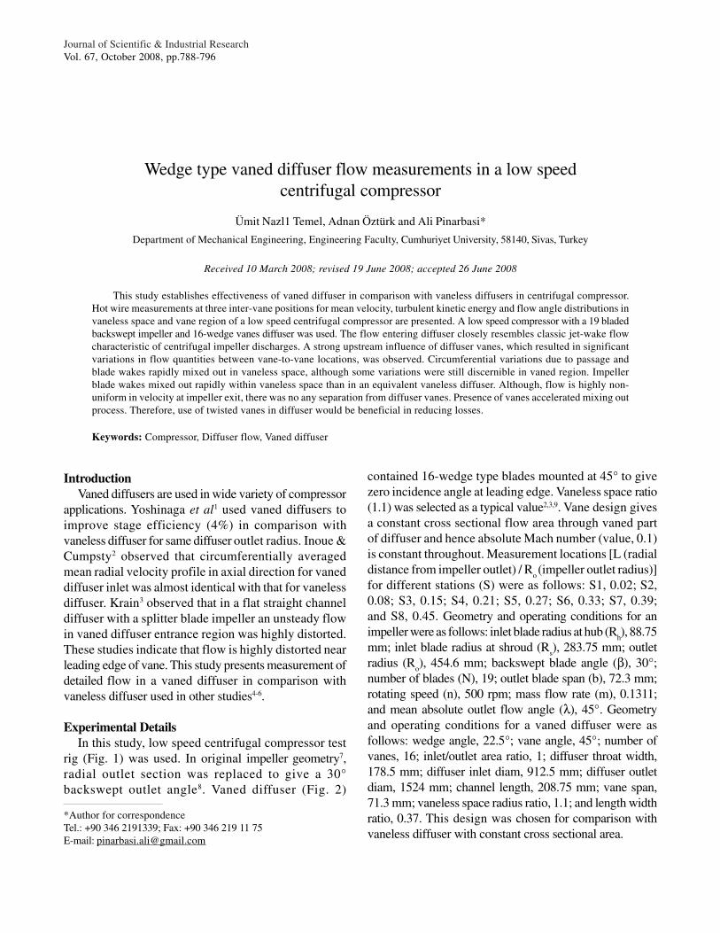
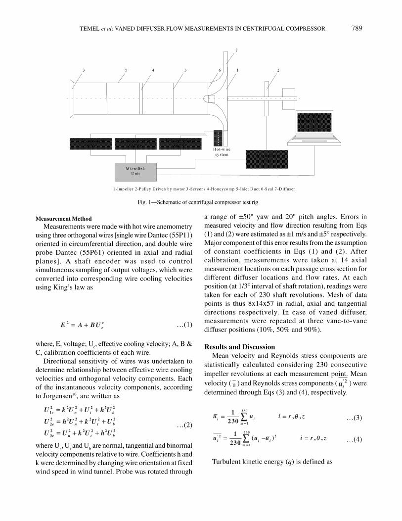
In this study, low speed centrifugal compressor testrig (Fig. 1) was used. In original impeller geometry7,radial outlet section was replaced to give a 30°backswept outlet angle8. Vaned diffuser (Fig. 2)
contained 16-wedge type blades mounted at 45° to givezero incidence angle at leading edge. Vaneless space ratio(1.1) was selected as a typical value2,3,9. Vane design givesa constant cross sectional flow area through vaned partof diffuser and hence absolute Mach number (value, 0.1)is constant throughout. Measurement locations [L (radialdistance from impeller outlet) / R
o (impeller outlet radius)]
for different stations (S) were as follows: S1, 0.02; S2,0.08; S3, 0.15; S4, 0.21; S5, 0.27; S6, 0.33; S7, 0.39;and S8, 0.45. Geometry and operating conditions for animpeller were as follows: inlet blade radius at hub (R
h), 88.75
mm; inlet blade radius at shroud (Rs), 283.75 mm; outlet
radius (Ro), 454.6 mm; backswept blade angle (β), 30°;
number of blades (N), 19; outlet blade span (b), 72.3 mm;rotating speed (n), 500 rpm; mass flow rate (m), 0.1311;and mean absolute outlet flow angle (λ), 45°. Geometryand operating conditions for a vaned diffuser were asfollows: wedge angle, 22.5°; vane angle, 45°; number ofvanes, 16; inlet/outlet area ratio, 1; diffuser throat width,178.5 mm; diffuser inlet diam, 912.5 mm; diffuser outletdiam, 1524 mm; channel length, 208.75 mm; vane span,71.3 mm; vaneless space radius ratio, 1.1; and length widthratio, 0.37. This design was chosen for comparison withvaneless diffuser with constant cross sectional area.
TEMEL et al: VANED DIFFUSER FLOW MEASUREMENTS IN CENTRIFUGAL COMPRESSOR 789
Measurement Method
Measurements were made with hot wire anemometryusing three orthogonal wires [single wire Dantec (55P11)oriented in circumferential direction, and double wireprobe Dantec (55P61) oriented in axial and radialplanes]. A shaft encoder was used to controlsimultaneous sampling of output voltages, which wereconverted into corresponding wire cooling velocitiesusing King’s law as
2 c
eE A BU== ++ …(1)
where, E, voltage; Ue, effective cooling velocity; A, B &
C, calibration coefficients of each wire.Directional sensitivity of wires was undertaken to
determine relationship between effective wire coolingvelocities and orthogonal velocity components. Eachof the instantaneous velocity components, accordingto Jorgensen10, are written as
2 2 2 2 2 2
1
2 2 2 2 2 2
2
2 2 2 2 2 2
3
e n t b
e n t b
e n t b
U k U U h U
U h U k U U
U U k U h U
== ++ ++
= += + ++
== ++ ++…(2)
where Un, U
t and U
b are normal, tangential and binormal
velocity components relative to wire. Coefficients h andk were determined by changing wire orientation at fixedwind speed in wind tunnel. Probe was rotated through
a range of ±50° yaw and 20° pitch angles. Errors inmeasured velocity and flow direction resulting from Eqs(1) and (2) were estimated as ±1 m/s and ±5° respectively.Major component of this error results from the assumptionof constant coefficients in Eqs (1) and (2). Aftercalibration, measurements were taken at 14 axialmeasurement locations on each passage cross section fordifferent diffuser locations and flow rates. At eachposition (at 1/3° interval of shaft rotation), readings weretaken for each of 230 shaft revolutions. Mesh of datapoints is thus 8x14x57 in radial, axial and tangentialdirections respectively. In case of vaned diffuser,measurements were repeated at three vane-to-vanediffuser positions (10%, 50% and 90%).
Results and Discussion
Mean velocity and Reynolds stress components arestatistically calculated considering 230 consecutiveimpeller revolutions at each measurement point. Meanvelocity ( u ) and Reynolds stress components ( '2
iu ) weredetermined through Eqs (3) and (4), respectively.
230
1
1 , ,
230i i
m
u u i r zθθ==
== ==∑∑ …(3)
230'2 2
1
1( ) , ,
230i i i
m
u u u i r zθθ==
== −− ==∑∑ …(4)
Turbulent kinetic energy (q) is defined as
1 . A nem o m ete r 5 6C 0 1
2 . A nem o m ete r 5 6C 0 1
3 . A nem o m ete r 5 6C 0 1
H o t-w ire sy stem
M icro link U nit
M icro link U nit
8 02 8 6 M icro C o m p ute r
1 2 3 4 5 6 3
7
1 -Im p e lle r 2-Pulley D r iven b y m o to r 3 -Screens 4 -H o neyco m p 5-Inle t D uc t 6 -Sea l 7 -D iffus e r
Fig. 1—Schematic of centrifugal compressor test rig
790 J SCI IND RES VOL 67 OCTOBER 2008
'2 '2 '2230
1
1
230 2
r z
m T
u u uq
U
θθ
==
++ ++== ∑∑ …(5)
where UT is blade velocity at impeller outlet; u
¸, u
r, u
z,
tangential, radial and axial mean velocity components.'uθ
, '
ru , '
zu tangential, radial and axial r.m.s fluctuating
velocity components.An error analysis indicated that uncertainties in mean
velocity components were: Reynolds stress, ± 0.1% ± 1m/s; and turbulent kinetic energy, ± 0.05% ± 1 m/s.Majority of this error results from assumption ofconstant coefficients in Eqs (1) and (2).
Station Results
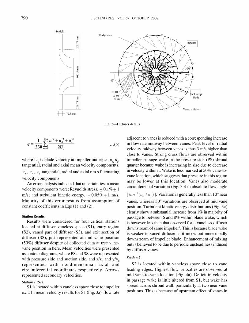
Results were considered for four critical stationslocated at diffuser vaneless space (S1), entry region(S2), vaned part of diffuser (S3), and exit section ofdiffuser (S8), just represented at mid vane position(50%) diffuser despite of collected data at tree vane-vane position in here. Mean velocities were presentedas contour diagrams, where PS and SS were representedwith pressure side and suction side, and z/z
0 and y/y
0
represented with nondimensional axial andcircumferential coordinates respectively. Arrowsrepresented secondary velocities.
Station 1 (S1)
S1 is located within vaneless space close to impellerexit. In mean velocity results for S1 (Fig. 3a), flow rate
adjacent to vanes is reduced with a corresponding increasein flow rate midway between vanes. Peak level of radialvelocity midway between vanes is thus 3 m/s higher thanclose to vanes. Strong cross flows are observed withinimpeller passage wake in the pressure side (PS) shroudquarter because wake is increasing in size due to decreasein velocity within it. Wake is less marked at 50% vane-to-vane location, which suggests that pressure in this regionmay be lower at this location. Vanes also moderatecircumferential variation (Fig. 3b) in absolute flow angle
[ 1( / )rtan u uθ− ]. Variation is generally less than 10° near
vanes, whereas 30° variations are observed at mid vaneposition. Turbulent kinetic energy distributions (Fig. 3c)clearly show a substantial increase from 1% in majority ofpassage to between 6 and 8% within blade wake, whichis however less than that observed for a vaneless diffuserdownstream of same impeller4. This is because blade wakeis weaker in vaned diffuser as it mixes out more rapidlydownstream of impeller blade. Enhancement of mixingout is believed to be due to periodic unsteadiness inducedby diffuser vanes.
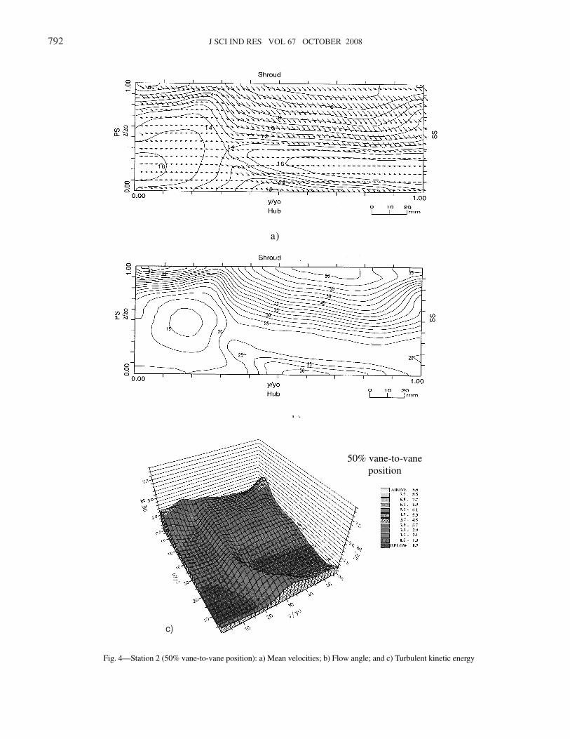
Station 2
S2 is located within vaneless space close to vaneleading edges. Highest flow velocities are observed atmid vane-to-vane location (Fig. 4a). Deficit in velocityin passage wake is little altered from S1, but wake hasspread across shroud wall, particularly at two near vanepositions. This is because of upstream effect of vanes in
912.
5 m
m
208.
75 m
m
208.
75 m
m
72.3 mm
Straight
Backswept blade
Impeller
30o
Vaned diffuser
45o
% 10
% 50
% 90
1
8
Wedge vane
Fig. 2—Diffuser details
TEMEL et al: VANED DIFFUSER FLOW MEASUREMENTS IN CENTRIFUGAL COMPRESSOR 791
50% vane-to-vane position
Fig. 3—Station 1 (50% vane-to-vane position): a) Mean velocities; b) Flow angle; andc) Turbulent kinetic energy
a)
b)
c)
792 J SCI IND RES VOL 67 OCTOBER 2008
a)
b)
Fig. 4—Station 2 (50% vane-to-vane position): a) Mean velocities; b) Flow angle; and c) Turbulent kinetic energy
50% vane-to-vane
position
c)
TEMEL et al: VANED DIFFUSER FLOW MEASUREMENTS IN CENTRIFUGAL COMPRESSOR 793
a)
b)
5 0 % v a n e -to -v a n e p o s it io n
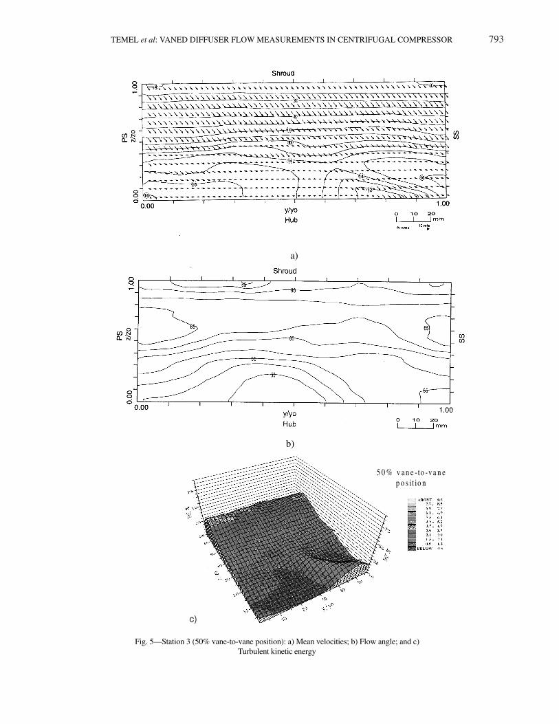
Fig. 5—Station 3 (50% vane-to-vane position): a) Mean velocities; b) Flow angle; and c)Turbulent kinetic energy
c)
794 J SCI IND RES VOL 67 OCTOBER 2008
moderating circumferential variations in tangential/radial flow angle (<10°). There is however significantvariation in flow angle in axial direction and so sometwisting of leading blade edges would be beneficial (Fig.4b). Passage wake has moved across the shroud becauseof tangential velocity between S1 and S2. Blade wake hasalso moved in this direction. This is due to increase inradial/tangential flow angle due to decrease in radialvelocity. Close proximity of vanes also has a significantmoderating effect on secondary velocities, which are
largest at mid vane position. Turbulent kinetic energydiagram (Fig. 4c) shows how level within blade wakehas decreased substantially from S1. Increase in widthof blade wake is also clearly depicted. However, littlechange is observed in kinetic energy within passage wake.These observations are similar to those made for vanelessdiffuser4, where high level of kinetic energy was onlyassociated with high levels of Reynolds stress in bladewake. High levels of kinetic energy in passage wake
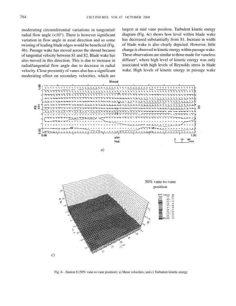
Fig. 6—Station 8 (50% vane-to-vane position): a) Mean velocities; and c) Turbulent kinetic energy
50% vane-to-vane
position
c)
a)
TEMEL et al: VANED DIFFUSER FLOW MEASUREMENTS IN CENTRIFUGAL COMPRESSOR 795
Vaneless
10%
50%
90%
Pe
ak le
ve
l of T
KE
(%
)
were attributed to low frequency meandering of wakeposition.
Station 3
S3 is located within vaned part of diffuser.Circumferential variations in velocity (Fig. 5a) are nowgenerally small. Maximum deficit in velocity is withinblade wake at mid vane position, where strongestsecondary velocities are also observed. Krain3 andInoue11 also support these observations. Flow angles(Fig. 5b) indicate little circumferential variation andvariations in axial direction have also moderated fromS2 due to guiding effect of vanes. Flow does have asignificantly different direction at mid vane position.Under kinetic energy diagram (Fig. 5c), levels withinpassage wake reduced slightly from S1.
Station 8
Mean velocities (Fig. 6a) show only negligiblevariations in circumferential direction. Axial componentof velocity is also small except near shroud at mid vaneposition. Cross velocities appear to be associated withthickening shroud boundary layer, which is substantiallythicker at mid vane position than near the vanes.Turbulent kinetic energy level (Fig. 6c) is more or lessuniform across passage with a modest increase in shroudboundary layer at mid vane position.
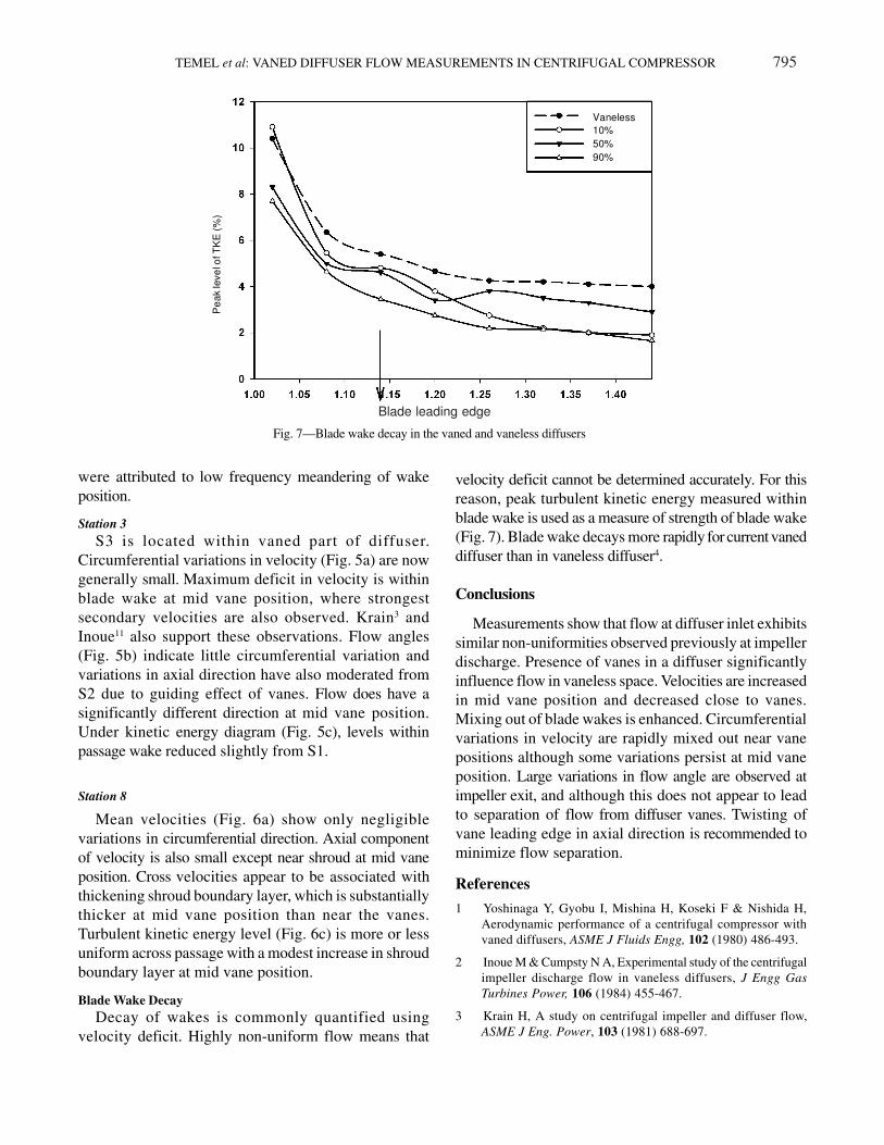
Blade Wake Decay
Decay of wakes is commonly quantified usingvelocity deficit. Highly non-uniform flow means that
velocity deficit cannot be determined accurately. For thisreason, peak turbulent kinetic energy measured withinblade wake is used as a measure of strength of blade wake(Fig. 7). Blade wake decays more rapidly for current vaneddiffuser than in vaneless diffuser4.
Conclusions
Measurements show that flow at diffuser inlet exhibitssimilar non-uniformities observed previously at impellerdischarge. Presence of vanes in a diffuser significantlyinfluence flow in vaneless space. Velocities are increasedin mid vane position and decreased close to vanes.Mixing out of blade wakes is enhanced. Circumferentialvariations in velocity are rapidly mixed out near vanepositions although some variations persist at mid vaneposition. Large variations in flow angle are observed atimpeller exit, and although this does not appear to leadto separation of flow from diffuser vanes. Twisting ofvane leading edge in axial direction is recommended tominimize flow separation.
References
1 Yoshinaga Y, Gyobu I, Mishina H, Koseki F & Nishida H,Aerodynamic performance of a centrifugal compressor withvaned diffusers, ASME J Fluids Engg, 102 (1980) 486-493.
2 Inoue M & Cumpsty N A, Experimental study of the centrifugalimpeller discharge flow in vaneless diffusers, J Engg Gas
Turbines Power, 106 (1984) 455-467.
3 Krain H, A study on centrifugal impeller and diffuser flow,ASME J Eng. Power, 103 (1981) 688-697.
Fig. 7—Blade wake decay in the vaned and vaneless diffusers
Blade leading edge
796 J SCI IND RES VOL 67 OCTOBER 2008
4 Pinarbasi A & Johnson M W, Detailed flow measurements in acentrifugal compressor vaneless diffuser, J Turbomachinery,116 (1994) 453-461.
5 Pinarbasi A. & Johnson M W, Off design measurements in acentrifugal compressor vaneless diffuser, J Turbomachinery,117 (1995) 602-610.
6 Pinarbasi A & Johnson M W, Detailed stress tensormeasurements in a centrifugal compressor vaneless diffuser, JTurbomachinery, 118 (1996) 394-399.
7 Johnson M.W & Moore J, The development of wake flow in acentrifugal compressor, ASME J Engg Power, 102 (1980) 383-390.
8 Farge T Z & Johnson M W, The effect of backswept bladingon the flow in a centrifugal compressor impeller, ASME pap
90-GT-231, 1990.9 Hayami H, Senoo Y & Utsunomiya K, Application of a low
speed solidity cascade diffuser to transonic centrifugalcompressor, ASME J Turbomachinery, 112 (1990) 25-29.
10 Jorgensen F E, Directional sensitivity of wire and fibre film probes,DISA Inform, 11 (1971) 31-37.
11 Inoue M, Centrifugal compressor diffuser studies, Ph D Thesis,University of Cambridge, 1980.
12 Zangeneh M, Inverse design of centrifugal compressor vaneddiffusers in inlet shear flows, ASME pap 94-GT-144, 1994.


![Klimaoprema katalog PPZEN DIFFUSER SLOT DIFFUSER ... Selection diagrams ... - Air velocity between two diffusers L [m] - Diffuser length B min](https://img.pdfslide.net/doc/110x75/5a9ff9c87f8b9a71178d6c6b/pdfklimaoprema-katalog-diffuser-slot-diffuser-selection-diagrams-air.jpg)