Embed Size (px)
Citation preview
We are glad that you have decided on one of the precious WEDICO truck models! For the manufacture of individual parts WEDICO uses durable materials of high quality - rarely to find in these days. This guarantees durability and enjoyment of your model for years to come. If you should ever require replacement parts, please get in touch with your dealer or directly with WEDICO. For order purpose it is im-portant using not only those EDP-numbers mentioned within the gen-eral parts list (see last page of this instruction) but also indicating the necessary details concerning colour, quantity and exact term of the spares required. You may be assured that WEDICO will supply the re-placement part as quick as possible.
54.DOC / K-Fre 29.01.2004 Page 1
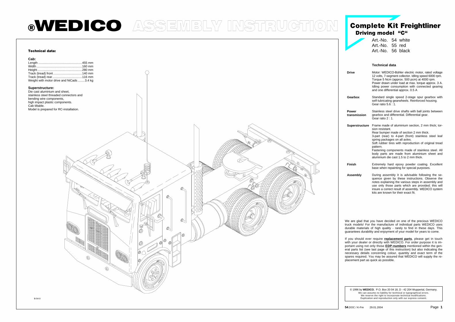
qÉÅÜåáÅ~ä=Ç~í~W Cab: Length ..................................................455 mm Width ....................................................160 mm Height ...................................................280 mm Track (tread) front .................................140 mm Track (tread) rear..................................116 mm Weight with motor drive and NiCads ........3.4 kg Superstructure: Die cast aluminium and sheet, stainless steel threaded connectors and bending wire components, high impact plastic components. Cab tiltable. Model is prepared for RC-installation.
®WEDICO Art.-No. 54 white
Art.-No. 55 red Art.-No. 56 black
`çãéäÉíÉ=háí=cêÉáÖÜíäáåÉê=aêáîáåÖ=ãçÇÉä==�`�=
B-54-0
Technical data
Drive Motor: WEDICO-Bühler electric motor, rated voltage12 volts, 7-segment collector. Idling speed 6000 rpm. Torque 5 Ncm (approx. 500 pcm) at 4000 rpm. Power drawn under load at max. torque approx. 3 A.Idling power consumption with connected gearing and one differential approx. 0.5 A
Gearbox Standard single speed 2-stage spur gearbox with self-lubricating gearwheels. Reinforced housing. Gear ratio 5.6 : 1.
Power transmission
Stainless steel drive shafts with ball joints between gearbox and differential. Differential gear. Gear ratio 2 : 1.
Superstructure
Frame made of aluminium section, 2 mm thick; tor-sion resistant. Rear bumper made of section 2 mm thick. 3-part (rear) to 4-part (front) stainless steel leaf spring packages on all axles. Soft rubber tires with reproduction of original tread pattern. Fastening components made of stainless steel. All body parts are made from aluminium sheet and aluminium die cast 1.5 to 2 mm thick.
Finish Extremely hard epoxy powder coating. Excellent base when repainting for special purposes.
Assembly During assembly it is advisable following the se-quence given by these instructions. Observe the notes explaining the various steps in assembly and use only those parts which are provided; this will insure a correct result of assembly. WEDICO systemkits are known for their exact fit.
© 1996 by WEDICO, P.O. Box 20 04 18, D - 42 204 Wuppertal, Germany. We can assume no liability for technical or typographical errors.
We reserve the right to incorporate technical modifications. Duplication and reproduction only with our express consent.

`çãéäÉíÉ=háí==cêÉáÖÜíäáåÉê=
`çãéäÉíáçå=çÑ=~ëëÉãÄäó=Öêçìéë
10
276
275 289
271
290
102
291
101
10
713
292
105 279
13
288
10
293
289
713
276
10
56
10
105
115
109
115
109
109
115
109
114
24
24
11424
24
274
24
N ^ëëÉãÄäó=çÑ=íÜÉ=Ñêçåí=ëÉÅíáçå=1.1 Preparation for assembly
The holes in the front panel 271 are provided to accept self-cutting screws 10 and 111. Before starting assembly, use one of the self-cutting screws 111 to cut threads in all ten holes. You should lubri-cate the screw and the screw holes (using a little petroleum jelly, for instance) before doing so and afterwards use a soft cloth to remove excess lubricant.
1.2 Assembling the front section Located at the outside left and right on the inside of the front section are two holes to accept screws. Use two self-cutting screws 10 each to affix the two door hinges 105. Here the upper and lower pins are held between the side wall and the screw heads. Slide the tilting hinge 101 over the pin 102 and use two additional self-cutting screws 10 to press the pin into the horizontal depressions at the two screw holes located at the radiator opening; the pin is held in place with the screw heads. Now remove the protecting foil from both sides of the front screens 279 and use a universal glue to affix the front screen. Allow the glue to set before continuing assembly. Then use the tap-ping screw 293 to attach the steering wheel 56 to the dashboard 288. The dashboard is then attached to the front panel using self-cutting screws 10 and washers 13.
1.3 Installing the headlamps First thread the leads from each bulb 713 through the two holes in the lamp supports 292. The headlamp caps 290, 291 and 292 are af-fixed to the front panel with screws 115, washers 24 and nuts 109.
1.4 Attaching the side components The fenders 274 and 275 are attached with one each screw 114, washer 24 and nut 109 to the fillets 276. Then attach these units with two each screws 115, washers 24 and nuts 109 each at the side of the front panel. Thread one bulb lead 713 each through the corre-sponding opening as shown in the drawing and then seat the lens 289.
Identification of Parts in Assembly Plan M3 hex nuts are not provided with an identification number. This assembly instruction is built up as follows: on the left side you will find the drawing of the assembling groups; on the right side, marked by the corresponding number of illustration, the instructions for the proper assembly. Next to them on the same page are not only parts lists indicating the necessary components for the actual step of construction but also some special and helpful hints.
Screws, washers, etc. at 1:1 For better identification of different screws and washers we give you an illustration of the most important parts in original scale. Not illustrated parts are to be identified by compare. Do you seek for instance a screw M3 x 30, it must be 5 mm longer than the screw M3 x 25, which is shown in the drawing.
Assembling the front section ill. 1
54-e.DOC / K-Fre Page 2
M4 x 25 Part no. 18
M4 x 8 Part no. 17
M3 x 25 Part no. 6
M3 x 20 Part no. 5
M3 x 16 Part no. 4
M3 x 12 Part no. 3
M3 x 8 Part no. 2
M3 x 6 Part no. 1
M2 x 8 Part no. 115
M2 x 6 Part no. 114
Self-cutting screw M3 x 8 Part no. 111
Self-cutting screw M3 x 6 Part no. 10
Tapping screw 3.5 x 9.5 Part no. 293
Tapping screw 2.2 x 4.5 Part no. 21
Countersunk tapping screw 2.2 x 4.5 Part no. 564
Stud bolt M3 x 18 Part no. 16
Nut M4 Part no. 19
Nut M3 ---
Nut M2 Part no. 109
Square nut M3 Part no. 12
Knurled nut M5 Part no. 210
Washer 4.3 Part no. 20
Washer 3.2 Part no. 13
Washer 2.2 Part no. 24
Spring washer 3.2 Part no. 14
Serrated washer 3.2 Part no. 15
Retaining washer 3.2 Part no. 25
B-54-1
Qty. No. Assembly part 1 275 Fender -rh- 2 276 Fillet 2 279 Front screen 1 288 Dashboard 2 289 Lens for roof lamp,
orange 2 290 Headlight cap 2 291 Headlight lens 2 292 Lamp support 1 293 Tapping screw
3.5 x 9.5 6 713 Bulb 3V, 100mA
ill. 1
Qty. No. Assembly part 8 10 Self-tapping screw
M3 x 6 2 13 Washer 3.2
10 24 Washer 2.2 1 56 Steering wheel 1 101 Tilting hinge 1 102 Pin for tilting hinge 2 105 Door hinge
10 109 Nut M2 2 114 Screw M2 x 6 8 115 Screw M2 x 8 1 271 Front panel 1 274 Fender -lh-

`çãéäÉíÉ=háí==cêÉáÖÜíäáåÉê=
`çãéäÉíáçå=çÑ=~ëëÉãÄäó=Öêçìéë
15
568
707
2613
2613
655
707
1915
19
713
289
706
706
713
4
4
945
109
109
109
109
109
109
109
109
109
13
383
372
1626
96
383
285
12
1626
285 2
2
28
13
96
12
93
95
28
24
24
24
284
24
24
407
284
416
O ^ëëÉãÄäó=íÜÉ=êççÑ=ëÉÅíáçå=2.1 Horns, roof lamps and antenna socket
The horns 707 are fitted with spring bushings 26 and washers 13 and affixed, through the holes provided in the roof 945, using screws 4, M3 nuts and serrated washers 15. Install a bulb 713 in each of the roof lamps 706, threading the leads through the lamp housings first. The cables are easier to thread if you twist the two conductors together and bend the ends slightly. Pointed tweezers can help in pulling the cable through. Do not pull the bulbs too far into the lamp housings; the bulbs should protrude by 2 to 3 mm. After the roof lamp lenses 289 have been pressed onto the lamp housings, the housings are inserted in the holes in the roof and secured with nuts 19. The bulb leads and the red/black cable from the switch panel are at-tached to the terminal strip (see Section 14.3 and Fig 14). Use adhe-sive pads 655 to affix the terminal strip under the roof so that the ca-bles are not visible inside the cab. Affix the components for the antenna socket 568 as shown in the il-lustration. Note that the antenna cable from the remote control re-ceiver will have to be soldered to the antenna socket.
P ^ëëÉãÄäáåÖ=íÜÉ=êÉ~ê=é~åÉä=ëÉÅíáçå=3.1 Assembling the exhaust system
Slide one square nut 12 each into the depressions at the muffler caps 96. Now slide these caps into the muffler 93 so that the nut is located behind the hole. Slide the exhaust tail pipe 95 from above into the muffler cap until catching; clamp it in place with a stud 16. Ensure that the tip of the exhaust pipe points is aligned with the nut. Follow the same procedure for the exhaust manifold 416. Its lower opening must also be aligned with the nut. Then a spring bushing 26 and washer 13 are slid onto the two studs. Now insert the exhaust system, i.e. the studs and the exhaust manifold, through the mating holes at the rear panel 407 and secure with the M3 nuts. Press the fixing caps 383 from above and below onto the muffler and slide the exhaust screen 372 over them.
3.2 Mounting the grab rails and angles
���� If you wish to apply decorative decals later, the grab rails previ-ously mounted will now be in the way. In this case the assembly procedure described here can be effected only after Section 4.2.
Turn one each nut 109 and washer 24, the angle 284 and an addi-tional nut 109 onto the threads on the grab rail 285; position the nuts so that the upper end of the thread protrudes a maximum of 1 mm beyond the nut. Accordingly, the lower thread section will extend 3 mm out of the nut. Then use screws 2, M3 nuts and threaded bush-ings 28 to mount the angle as shown.
Assembling the roof section ill. 2
Assembling the rear panel section ill. 3
���� Attention! Risk of short! Please carefully cut off the solder pins on the terminal strip -roof lamp- otherwise you run risk of short!
54-e.DOC / K-Fre Page 3
For threading the bulb leads see proper text
Please clip off the solder pins
Terminal strip for roof lamps
B-54-3
B-54-3
Qty. No. Assembly part 2 95 Exhaust tail pipe 4 96 Muffler cap
16 109 Nut M2 2 284 Angle 4 285 Grabrail long 2 372 Exhaust screen 4 383 Fixing cap 1 407 Rear panel, Complete
Kit Freightliner “C“ 2 416 Exhaust manifold
ill. 3
Qty. No. Assembly part 8 --- Nut M3 4 2 Screw M3 x 8 4 12 Square nut M3 4 13 Washer 3.2 4 16 Stud M3 x 18 8 24 Washer 2.2 4 26 Bushing 4 28 Threaded bushing
M3 x 20 2 93 Muffler
Qty. No. Assembly part 1 655 Adhesive pad,
doublesided 5 706 Roof lamp, chromed 2 707 Horn 5 713 Bulb 3V, 100 mA 1 945 Roof, Complete Kit
Freightliner “C“ 1 --- Terminal strip for roof
lamps
ill. 2
Qty. No. Assembly part 2 --- Nut M3 2 4 Screw M3 x 16 2 13 Washer 3.2 2 15 Serrated washer 3.2 5 19 Nut M4 2 26 Bushing 5 289 Lens for roof lamp,
orange 1 568 Antenna socket,
complete

`çãéäÉíÉ=háí==cêÉáÖÜíäáåÉê=
`çãéäÉíáçå=çÑ=~ëëÉãÄäó=Öêçìéë
13
277
2 13
75
13
80
1276
132
2
15 15
111
109
109
109
14
24
24114
114
Assembling the cab ill. 4
View from below showing the location of components mounted onto the frame ill. 5
54-e.DOC / K-Fre Page 4
Q ^ëëÉãÄäáåÖ=íÜÉ=Å~Ä=4.1 Mounting the cab
First use the self-cutting screws 111 and the serrated washers 15 to attach the roof to the front panel. The rear panel is now attached to the roof with screws 2, washers 13, serrated washers 15 and M3 nuts. The two access steps 277 are attached to the rear panel and the fenders with screws 114, washers 24 and nuts 109. Ensure that there is a nut 109 between the rear panel and the access steps.
4.2 Decorative decals and logo Now you can, if desired, apply the decal. First attach the doors with just one screw 2, washer 13 and M3 nut at the bottom of each hinge. Then attach the decal at the front panel, doors and rear panel. The grab rails can now be mounted at the rear panel as described in Sec-tion 3.2. The "Freightliner" logo is affixed to the front panel.
4.3 Mounting the doors Now you can affix the doors at the top of the hinges. Turn an M3 nut onto the door handle 75 and tighten it down. Then slide on a washer 13 and insert the handle through the hole provided in the door. Mount the spring washer 14 from the rear, screw on a square nut 12 and slide the door lock 76 over this. The door handle and the door lock must be positioned so that they are opposed. To do this, you may want to hold the door lock with a pliers while turning down the nut.
R mêÉîáÉï=çÑ=íÜÉ==ÉäÉÅíêáÅ~ä=ëóëíÉã=áåëí~ää~íáçå=
The illustration at the left shows the locations of the circuit boards and the routing of the ribbon cable beneath the frame. The cable will have to be installed underneath the frame before the electrical de-vices are installed in their entirety. The cable should run between the frame and the axles, the fifth-wheel shaft and the screws used to af-fix the tank. If the cable were to be laid later it would be necessary to disassemble some components already installed. The best course of action is to read all the information on the electri-cal system in Chapter 14 before you begin assembling the compo-nents on the frame. This will give you an idea of which components will be connected by cable.
Steering servo Front PCB Ribbon cable Tank Differential Rear axle Rear PCB
Blinker switch Gear Speed controller
B-54-4
B-54-4
Qty. No. Assembly part 2 76 Door lock 2 80 Door 8 109 Nut M2 2 111 Self tapping screw
M3 x 8 6 114 Screw M2 x 6 2 277 Access steps, chromed --- Decal
ill. 4
Qty. No. Assembly part 10 --- Nut M3 6 2 Screw M3 x 8 2 12 Square nut M3 8 13 Washer 3.2 2 14 Spring washer 3.2 4 15 Serrated washer 3.2 6 24 Washer 2.2 2 75 Door handle

`çãéäÉíÉ=háí==cêÉáÖÜíäáåÉê=
`çãéäÉíáçå=çÑ=~ëëÉãÄäó=Öêçìéë
655
723 722
721
721
720
719
2
655
13
929
760
13
4
45564
564
724
908
908
13
13
1390
789
30
3 13
26
13
13
2613
3
3233
1820
27
52
20
2
29
36
55
19
19
2
20
5
1820
27
52
53
53
29
30
30
36
5
3233 13
3 13
26
3 13
13
26
109
41
42
41
4
34
34
441
41
41
Assembling the front axle section ill. 7
Components attached to the front frame ill. 6
S `çãéçåÉåíë=~íí~ÅÜÉÇ=íç=íÜÉ=Ñêçåí=Ñê~ãÉ=6.1 Mounting the servo installation set
With screws 2 and nuts M3 start by mounting the servo supporting angle 760 underneath the frame 45. Together with washers 13 lead now two screws 4 through those long holes provided on the servo supporting angle. Slide then each two additional washers 13 and the steering servo onto this unit and fix it using each one washer 13 and nut M3. After-wards affix the servo supporting angle underneath the frame.
6.2 Mounting the PCB support Use two adhesive pads 655 to affix the support 723 behind the servo supporting angle under the frame.
6.3 Assembling the blinker switch Slide two single-bent springs 721 into the corresponding holes and slots in the base plate 720. Insert the double-bent spring 722 into the two holes on the lever blinker switch 724 and then place the eye of the lever over the boss on the base plate. The cover plate 719 is now secured to the base plate with countersunk screws 564. Attach the blinker switch with two adhesive pads 655 that way onto the steering servo, that the clamp-type connector 929 lays closely on the fore edge of the housing.
T ^ëëÉãÄäáåÖ=íÜÉ=Ñêçåí=~ñäÉ=ëÉÅíáçå=7.1 Mounting the suspension with front axle
First install the screws 3 together with washers 13, bushings 26, and M3 nuts at the rearward holes in the frame, provided for attaching the springs. Then attach the open ends of the two long spring leaves 32 at the bushings and use an identical set of parts to screw the closed ends to the front of the frame 45. One nut 19 each is pressed into the hexagonal depressions at the steering lever 42. Use two screws 5 and M3 nuts to attach to the long spring leafs, previously mounted, two medium spring leaves 33 and a short spring leaf 34 along with two half-axle guards 41, into which the front axle 55 and steering lever 42 have been inserted. Before tightening down the screws 5 ensure that the spring sets are not under tension and can move freely.
7.2 Mounting the wheels and steering linkage First mount the standard tyres 53 on the rims 52. Then use screws 18 and one washer 20 each in front of and behind the axle tube 27 located in the hub to bolt the wheels to the steering lever, using the nut already inserted. To the outer holes on the steering levers fix two screws 4 along with nuts M3. To this unit add now the track rod 1390 using washers 13 and stop nuts 908; do not tighten the stop nuts but leave the track rod moveable. With screws 2 fix two ball bolts 29 to the inner holes on the steering levers for the attachment of the steering rods. To a steering rod 36 add one nut 109, fork head 789 and ball socket 30. The steering rod has to be bent slightly, depending on the size of the servo unit. After-wards clip this steering rod for the servo linking to the left-hand ball bolt. For operation of the blinker switch, add to the right-hand ball bolt another steering rod 36, equipped with two ball sockets 30. Ad-just the distance between the ball sockets so that the wheels are in the straight-ahead position when the lever of the blinker switch is in its neutral setting.
54-e.DOC / K-Fre Page 5
Assembly of blinker switch
Ribbon cable from the switch
Steering servo (not incl. in the kit)
fully assembled blinker switch
gre
en
bro
wn
wh
ite
Frame
B-54-6
B-44-9 fre
For a better overview the illustration is showing an assembly without the parts attached to the front frame section
Moment of torsion of the servo should be at 30 Ncm. The servo supporting angle will fit servos with the following data: L x W x H: ........................41 x 20 x 38 mm Gauge for screwing ....................48 ±2 mm
Qty. No. Assembly part 2 32 Spring long, “AF“ 4 33 Spring medium, “AF“ 2 34 Spring short, “AF“ 2 36 Steering rod M2 x 50 4 41 Half-axle guard 2 42 Steering lever 2 52 Rim, chromed 2 53 Standard tyre
“Ecocontrol“ 1 55 Front axle 1 109 Nut M2 1 789 Fork head 2 908 Stop nut M3 1 1390 Track rod, flat
ill. 7
Qty. No. Assembly part 10 --- Nut M3 2 2 Screw M3 x 8 4 3 Screw M3 x 12 2 4 Screw M3 x 16 4 5 Screw M3 x 20
12 13 Washer 3.2 2 18 Hex head screw
M4 x 25 2 19 Nut M4 4 20 Washer 4.3 4 26 Bushing 4 x 0.5 x 7 2 27 Axle tube 2 29 Ball bolt M3 3 30 Ball socket
Qty. No. Assembly part 1 719 Cover for blinker switch 1 720 Base for blinker switch 2 721 Spring, single bent 1 722 Spring, double bent 1 723 PCB support, small 1 724 Lever for blinker switch 1 760 Servo angle 1, small 1 929 Clamp-type connector,
3-pole
ill. 6
Qty. No. Assembly part 4 --- Nut M3 2 2 Screw M3 x 8 2 4 Screw M3 x 16 8 13 Washer 3.2 1 45 Frame 3-axle chassis,
432mm 4 564 Countersunk tapping
screw 2.2 x 4.5 4 655 Adhesive pad,
double-sided

`çãéäÉíÉ=háí==cêÉáÖÜíäáåÉê=
`çãéäÉíáçå=çÑ=~ëëÉãÄäó=Öêçìéë
1160
1160
714156
717
6 15
13
13
1326
3 13
26
3332
3332
1326
13
13
3 13
26
68
7070
70
70
1720
1720
5252
3 13
26
3 1326
3332
131
13
66
12
12
32
13
13
2613
3
1 26
133
715
716
33
109
109
717
34
34
4
114
34
64
714
114
4
34
Note!
Sometimes it happens that the chromed rims sit too tightly on the axle (work tolerance); in this case remove a bit the chrome inside the rims, and lightly grease the running surface (e.g. using Vaseline).
57
57
723
655
655
211
73
717225
25
1
710
709
709
2
342341
342
341
47
46
74
44
Assembling the rear axle section ill. 9
Components attached to the rear frame ill. 8
U `çãéçåÉåíë=~íí~ÅÜÉÇ=íç=íÜÉ=êÉ~ê=Ñê~ãÉ=8.1 Mounting the fifth-wheel components
Attach the spring 74 to the link lever 44 with a screw 1 and M3 nut. Insert the bar 72 into the opening from above, securing it from below with the link lever and a tapping screw 21. Mount the fifth-wheel 71 from above, inserting the feet into the slots in the frame. Slide the shaft 73 through the holes at the side of the frame and the feet of the fifth-wheel, catching the free end of the spring 74 between the feet when doing so. The shaft is secured with two retaining washers 25.
���� Please ensure when attaching the fifth-wheel that the ribbon cable with the two circuit boards is located between the frame and the shaft (ill. 5).
8.2 Mounting the rear bumper assembly First insert the bulbs 713 in the lamp caps 709 as shown in the figure. Now affix the assembled caps to the rear bumper 47 using one each screw 57 and M3 nut. From the rear insert the lenses into the bumper: outwards the blinker lenses 341, inwards the rear light lenses 342. Attach the frame tail piece 46 underneath the frame using screws 1 and M3 nuts. Then the bumper and carrier plate 710 are set in front of the frame tail piece and attached with screws 2 and M3 nuts.
���� Take particular care that the bulb cables are not clamped between the bumper and the frame tail piece; this could cause a short cir-cuit!
Using two adhesive pads 655, affix the PCB support 723 on the front surface of the carrier plate, centred and flush with the bottom edge.
V ^ëëÉãÄäáåÖ=íÜÉ=êÉ~ê=~ñäÉ=ëÉÅíáçå=9.1 Mounting the mud guards
The mud guard support 715 is marked with an "X" and will later be mounted on the passenger’s side, the mud guard support 716 marked "O" on the driver's side. First attach to these supports the mud flaps 717 and the mud guards 714 with four screws 114 and nuts 109 each. Then use screws 6, serrated washers 15, bushings 26, two washers 13 and M3 nuts to attach the supports to the holes at the rear of the frame.
9.2 Mounting the rear spring set and axle Attach the open ends of the two long spring leaves 32 to the bushing and use a screw 3, bushing 26, washer 13 and M3 nut to screw the closed end to the frame. Press one each M3 nut into the hexagonal recess at the lower spring carrier 70. The axle 68 can now be mounted together with the spring carriers, one medium spring leaf 33 each, a short spring leaf 34 and screws 4.
���� Ensure that the end of the spring carrier 70 identified with an "M" is toward the wheel.
���� The ribbon cable with the two lamp PCBs should be mounted when attaching the rear axle and the differential!
9.3 Mounting the spring set and differential First attach the long spring leaves 32 to the frame. Once you have inserted one square nut 12 each into the grooves at the side of the differential the springs can be attached with screws 1. The differential has two cams on the wheel mounts; the grooves in the hubs are aligned exactly with these cams. The wheels are affixed using screws 17 (which will cut their own threads) and washers 20. Press the joint ball 64 into the joint socket at the mounted differential.
���� In no case should you use an M3 screw more than 6 mm long to affix the spring set as this would cause binding and damage the shafts on the differential!
9.4 Mounting the wheels Once you have mounted the drive axle tyres 1160 on the rims 52 the wheels are mounted on the shaft, with the wheel nuts facing one an-other and the chromed rims toward the outside; secure with a washer 20 and a screw 17. The wheels should turn easily but there should not be too much play.
54-e.DOC / K-Fre Page 6
Frame
Inserting the bulbs
Bulb for brake light
Bulb for blinker
Bulb for rear light
Frame
Drive shaft
B-54-9
B-44-10
(grey) (chromed)
Note!
The kit contains two additional red lenses 342 for the US chassis version equipped with red blinkers.
For a better overview the illustration is showing an assembly without rear bumper and fifth-wheel
Qty. No. Assembly part 1 73 Shaft for fifthwheel 1 74 Draw spring 2 341 Blinker lens high, orange 4 342 Lens/rear light high, red 2 655 Adhesive pad,
double-sided 2 709 Lamp cap 1 710 Carrier plate for
support PCB 6 713 Bulb 3V 1 723 PCB support, small
ill. 8
Qty. No. Assembly part 7 --- Nut M3 3 1 Screw M3 x 6 2 2 Screw M3 x 8 1 21 Tapping screw 2.2 x 4.5 2 25 Retaining washer 3.2 1 44 Link lever 1 46 Frame tail piece 1 47 Bumper, rear 2 57 Screw M3 x 10 1 71 Standard fifthwheel 1 72 Bar for kingpin
709
713
709

`çãéäÉíÉ=háí==cêÉáÖÜíäáåÉê=
`çãéäÉíáçå=çÑ=~ëëÉãÄäó=Öêçìéë
210
629
630
701
701
390
560
227
287 226
222 12
103
1
49
48
54 54
49
6454
1580 359
5
503
503
503
59
63 61 6260
2
391
2
58
5
13
2
708
Assembling and installing the rear seat panel ill. 10
Assembling the drive section ill. 11
NM ^ëëÉãÄäáåÖ=~åÇ=áåëí~ääáåÖ==íÜÉ=ëÉ~í=êÉ~ê=é~åÉä=
10.1 Mounting the switch panel Pass the switch toggles at the switch panel through the holes pro-vided in the seat rear panel 222; secure from the front using four knurled nuts 210. The jacks 701 attached to the PCB are clipped into the matching slots in the cab rear panel. The insulating discs, red 629 and black 630, are attached from the outside and secured with the knurled nuts 560. The black insulating disc serves to identify the jack with the two black conductors!
���� When installing the rear panel make sure that the solder lugs of the jacks do not touch!
The oval plug 390 is clipped in the unused holes in the cab rear panel.
10.2 Mounting the seat rear panel Onto the seat rear panel 222 attach now that label which indicates the switches (see drawing). The letters indicating the switches stand on their heads. For the assignment of the switches follow the illustra-tion 14b. Then turn two M3 nuts each onto the ends of the threaded rod 226 so that an inside clearance of about 35 mm remains. The threaded rod is then bolted to the seat rear panel 222 with the square nut 12 and M3 nut. The seat rear panel is now affixed from below with four screws 1, at the hexagonal bushes already mounted. Then insert the battery carrier plate 287, with the batteries in place, at an angle from below so that the two holes engage the ends of the grab rail projecting to the inside; the hole at the other end is slid onto the threaded rod and affixed there with a knurled nut 227. Now the seats 103 can be attached to the seat rear panel.
NN ^ëëÉãÄäáåÖ=íÜÉ=ÇêáîÉ=ëÉÅíáçå=11.1 Mounting the motor and gearbox
Use screws 2 to bolt the gear cover 59 to the motor 708 (we supply the white motor pinion 60 (14t.) already mounted to the motor shaft). Before assembling the gearing lubricate the gears and shafts lightly with Vaseline. Then clip the joint ball 64 in the gear wheel 62. Lay this gear wheel, the double pinion 61 with shaft 63 and -not to forget!- the shim 391 in the gear housing 58 and use screws 2 and M3 nuts to secure the gear housing to the cover. Once assembled, this unit is inserted from above into the opening in the frame and secured at the sides with screws 2, washers 13 and M3 nuts. At the same time the drive shaft 359 is inserted at the joint balls between the gearbox and the differential.
11.2 Mounting the tank and speed controller
���� When affixing the tank please ensure that the ribbon cable with the two PCBs are located between the frame and the screws used to affix the tank (Fig. 5).
Press the tank cap 49 into the tank tube 48. Now attach the tank and the speed controller 1580 to the frame. The insulation strips 503 must be wrapped around these two components in such a way that the re-inforcement, about 20 mm long, is located between the tank tube and the frame and that no contact with other components is possible. First use a screw 5 and an M3 nut to attach the straight ends of the clamp fittings 54 to the top of the frame. Now pass the other end around the tank or speed controller, clamping the insulating strips in between, and slide the free end from below the frame onto the threads of the screw 5. Now the tank and the speed controller are in contact with the frame. The cable exit at the speed controller should point to the front and toward the frame. The clamp fittings are secured from below with M3 nuts.
NOTE: Instead of the tank, to the left frame side you perfectly may add an Electronic Original Diesel Engine Noise, Art.-No. 189.
54-e.DOC / K-Fre Page 7
Switch panel
to front PCB
to battery
to blinker switch
to rear PCB
to terminal strip for roof lamps
to speed controller
to charging cable
Sticker for switch
Brake light green/yellow
to the radio receiver
Reinforcement
to battery
B-54-10
B-54-11
Qty. No. Assembly part 1 61 Double pinion 1 62 Gear wheel with joint
socket 1 63 Shaft for gear 116 1 64 Ball joint 1 359 Drive shaft 145mm 1 391 Shim 5 x 10 x 1 4 503 Insulating strip 1 708 Bühler motor incl.
14 teeth pinion 1 1580 Speed controller,
round tank short
ill. 11
Qty. No. Assembly part 14 --- Nut M3 9 2 Screw M3 x 8 4 5 Screw M3 x 20 2 13 Washer 3.2 1 48 Tank tube, polished 2 49 Tank cap, flat 4 54 Clamp fitting, standard
frame 1 58 Case for gear 116 1 59 Cap for gear 116
(1) 60 Motor pinion white, 14teeth
Qty. No. Assembly part 1 287 Battery carrier plate 1 390 Welsh plug, oval 2 560 Knurled nut M6 1 629 Insulating disc, red 1 630 Insulating disc, black 2 701 Jack bush 1 --- Sticker for switch
ill. 10
Qty. No. Assembly part 5 --- Nut M3 4 1 Screw M3 x 6 1 12 Square nut M3 2 103 Seat 4 210 Knurled nut M5 1 222 Seat rear panel 1 226 Threaded rod M3 1 227 Knurled nut M3

`çãéäÉíÉ=háí==cêÉáÖÜíäáåÉê=
`çãéäÉíáçå=çÑ=~ëëÉãÄäó=Öêçìéë
4
14
75
1376
12
13
3 13
283
13273 272
92
109
109 114
228 278
280
282
281
281
282
718
655 406
NO jçìåíáåÖ=íÜÉ Å~Ä=First attach the cab locking device -comprising the door handle 75, square nut 12, door lock 76, washers 13, washer 14 and M3 nuts- to the frame, in the same way as described for the doors in Section 4.3. The cab can now be mounted on the frame. First use washers 13 and M3 nuts to attach the screws 3 to the angle 283. Then slide the angle with the screws from beneath and into the holes at the frame; position the cab tilt hinge from above and secure with M3 nuts. Now use screws 114 and nuts 109 to join the radiator 272 and the radiator grille 273. Bolt the bumper 92 to the radiator using screws 4, washers 13 and M3 nuts and then attach to the angle 283 using an additional M3 nut.
NP ^íí~ÅÜáåÖ=íÜÉ=ëã~ää=ÉñíÉêáçê==ÅçãéçåÉåíë=
The blades on the two windscreen wipers 228 must first be short-ened by about 7 mm at each end; then press the arms into the holes at the front panel. The two mirrors 281 are pressed onto the mirror supports 280 and 406 and these are then attached to the doors with three clips 282 each. The sun visor 278 is attached above the windshield with two adhe-sive pads 655. Insert the antenna 718 into the antenna socket after sliding the ball onto the tip of the antenna.
Attaching the small exterior components ill. 13
Mounting the cab ill. 12
54-e.DOC / K-Fre Page 8
B-54-12
B-54-13
Qty. No. Assembly part 6 282 Fixing clips 1 406 Mirror support -lh- 2 655 Adhesive pad,
doublesided 1 718 Antenna with ball
ill. 13
Qty. No. Assembly part 1 228 Windscreen wiper -lh- 1 228 Windscreen wiper -rh- 1 278 Sun visor, chromed 1 280 Mirror support -rh- 2 281 Mirror, chromed
Qty. No. Assembly part 2 76 Door lock 1 92 Front bumper 2 109 Nut M2 2 114 Screw M2 x 6 1 272 Radiator 1 273 Radiator grille 1 283 Radiator angle
ill. 12
Qty. No. Assembly part 14 --- Nut M3 2 3 Screw M3 x 12 2 4 Screw M3 x 16 2 12 Square nut M3 8 13 Washer 3.2 2 14 Spring washer 3.2 2 75 Door handle

Wiring diagram of the electrical equipment ill. 14
54-e.DOC / K-Fre Page 9
NQ qÜÉ=ÉäÉÅíêáÅ~ä=ëóëíÉã=The wiring diagram shows the cable connections for the individual electrical components.
14.1 Mounting the switching panel and lamp PCBs The switch panel is inserted into the seat rear panel of the cab. First connect the bulbs and cables and then clip the lamp PCBs in place at the front and rear in the supports provided for this purpose.
14.2 Information on the bulbs, troubleshooting All the bulbs are 3-volt bulbs connected in series. This means that the conductors are not each connected to the supply voltage, as in an automobile. Instead, the ends are joined one to another to form a chain and the ends of the chain are attached to the power supply. Consequently just a single defective bulb will interrupt the entire cir-cuit and none of the lamps in the chain will light. The best way to lo-cate the defective bulb is to use a cable to bypass each of the bulbs in the series, one after the other. When you bypass the defective bulb, the rest in the chain will light. The reason for using a series circuit, which may appear to be complicated, is the low power con-sumption. 3-volt bulbs use far less power than 12-volt bulbs in rela-tion to their brightness. The power consumed by a chain of up to five 3-volt bulbs is just 0.1 A in the series connection which we use; 12-volt bulbs, by comparison, would draw 0.3 A.
14.3 Wiring the roof lamps The bulb leads and the red and black cables from the switch panel are attached at the screw terminal strip for the roof lamps. Then attach the terminal strip under the roof as described in Section 2.1.
���� Be careful when clipping off the solder pins at the terminal strip as there is a danger of shorts!
14.4 Wiring at the rear lamp PCB (tail and brake lights, rear blinkers)
The red/black/yellow cable exiting the switch panel for the rear lamps are routed under the frame and to the rear and connected to the PCB - marked on the bottom with „H“ for rear - as shown in the illustration. The green/yellow brake light cable coming from the speed controller is also to be connected at this PCB. Once the bulb leads have been attached, the PCB is clipped in place at the support which was previ-ously affixed with adhesive pads. Explanation: The green/yellow brake light cable connects the brake light bulbs to ground when the vehicle is at a standstill. This circuitry incorporates an element which limits the current to 750 mA and will disable the circuit in case of an overload or short. Switching off the supply voltage for about one second will reset this element, provided that the reason for the malfunction has been corrected.
14.5 Wiring at the front lamp PCB (twin headlamps, front blinkers)
The green/yellow/grey cable serving the lamps at the front also exits from the switch panel and is routed below the frame and to the front in exactly the same fashion. After connecting to the PCB - marked on the bottom with „V“ for front - and connecting the bulb leads, the lamp PCB is clipped in place in the support previously mounted.
14.6 Wiring the blinker switch The green/brown/white cable for the blinker switch terminates in a clamp-type connector (see therefore ill. 14a on page 10). This con-nector is attached to the blinker switch (if the direction of travel does not correspond to the blinking, please rotate it through 180°), mounted beneath the steering servo, already illustrated in ill. 6.
`çãéäÉíÉ=háí==cêÉáÖÜíäáåÉê=
`çãéäÉíáçå=çÑ=~ëëÉãÄäó=Öêçìéë
Supplied with the kit:
No. Assembly part 568 Antenna socket 708 Drive motor 929 Clamp-type connector
1580 Speed controller, round tank short
--- Terminal strip, 6-pole for roof lamps
--- Blinker switch --- Drive battery 12 V --- Charging cable with AMP-plug --- Set of circuit boards f. complete
chassis with lamp PCBs --- Switch panel with jack bushes
Not supplied with the kit: RC receiver Steering servo Servo connecting cable Cable for receiver voltage
Blinker switch
Steering servo (not incl. in the kit)
white brown green
black
red
Brake light yellow/green
Motor
yellow
yellow
yellow
yellow
red
black
Antenna socket
brown/red/orange
Terminal strip roof lamps
Clamp type connector
red
blac
k
red
blac
k
yello
w
green
yellow grey Twin head lamps -lh-/-rh-
RE
CE
IVE
R
(not incl. in the kit)
to the battery box of the remote control system
or alternative to the switch panel (ill. 17)
Cable for receiver voltage (not incl. in the kit)
Speed controller
Antenna cable
blac
k
red
Blinker -lh-
Blinker -rh-
12V Battery
Switch panel
Charging cable
black
red
blue
Jack bush Jack bush
Knurled nut
Disc red
Knurled nut
Disc black
grey
gr
een
yello
w
Front lamp PCB
Set of circuit boards for chassis
Blinker -rh-
Blinker -lh-
Rear lamp PCB
blac
k
blac
k
red
yello
w
Brake lights
Rear lights yello
w/g
reen
red
blac
k
red
red
B-54-19
Control LED
red/black
V H V H Wiring bridge

`çãéäÉíÉ=háí==cêÉáÖÜíäáåÉê=
`çãéäÉíáçå=çÑ=~ëëÉãÄäó=Öêçìéë
Blinking LED
Hazard
warn
ing
Lig
hts
R
eceiv
er
Pow
er
/ C
harg
ing
Main
sw
itch
OFF
ON
red
blue
black = minus pole (-)
red = plus pole (+)
Charging cable
from the switch panel
Switch panel Plug for the connection to receiver battery
(+) red (5V)
(-) black
54-e.DOC / K-Fre Page 10
1. Put in the servo connecting cable in the matching colour sequence, the wire ends protruding about 10 mm.
3. Cut off the wire ends and insulate wires.
2. Carefully squeeze the clamp-type connector using a pair of pliers or better, a small vice, until the locks at the sides snick audibly into place.
B-44-15
14.7 Connecting the speed controller Connect the AMP socket with the yellow cables to the corresponding AMP plug at the drive motor, and the AMP plug with the red/black cables to the AMP socket at the switch panel. The connection of the green/yellow brake light cable has already been described in Section 14.4. The signal "brake light" is switched by minus line, and it is time-triggered: As soon as one changes the position of the control lever from either "forward" or from "reverse" to the neutral position (switched-off), the brake light starts lighting for approx. eight seconds. But as soon as the travelling operation is started again, the brake light stops automatically its blinking, even before having finished these eight seconds. Attach the connecting socket with the brown/red/orange cable to one of the receiver terminals. If the socket doesn't match the receiver, you will need to add an adapter cable (not making part of this kit).
14.8 Starting the electrical system (see switches, ill.14b) The electrical system is put into operation by turning on the main switch; the LED blinks. Then the transmitter and receiver are switched on, in this order. (Always switch off the receiver first and then the transmitter!) If a speed controller has been installed, the brake lights will go on. If the light switch is on, the headlamps, the roof lamps and the tail lamps will light.
NR qÜÉ=ëéÉÉÇ=ÅçåíêçääÉê=The WEDICO speed controller is matched to the WEDICO-Bühler motor. The electronics are permanently installed in a tank housing, which should never be opened! Never apply force as this could damage the speed controller and nullify any and all guarantee enti-tlements. Prior to its supply, each speed controller is individually tested and provided with a basic programming. In your particular case, probably this general basic programming may not be the opti-mal for the type of RC equipment you are using, but you of course may change it (for further details please refer to the section 15.2 "programming").
15.1 Starting the speed controller Switch the electrics on by the following sequence: start by the main switch of the Electr. System, then switch on the transmitter, and finally the receiver; keep your eye on the control LED. Before you make the motor starts working remote-controlled, it is the speed controller which has first to detect the programmed neutral position; this position sits approx. in the centre on the control lever of your transmitter unit. Once the speed controller has correctly detected said position, as a con-firmation the control LED starts blinking for a ten times term. Only then one may consider the speed controller as in state of readiness; and now the motor power can be controlled for both senses of direc-tion via the control lever.
15.2 How to programme the speed controller Continue paying your attention to the control LED. For the correct ad-justment of the control lever on the transmitter, set the shift controller in neutral position; slide then the control lever into that position at which you wish the motor to be "off". As a confirmation, lightly press the programming key "4" on the speed controller (refer to next para-graph). Do not move the control lever on the transmitter. Now, the speed controller detects the neutral position, and the control LED starts its ten times blinking. Immediately after the blinking activity has started, slide the control lever into the position for maximum "forward" speed; secure the lever at this point. Do not move it. Even after the 10th blinking, the control LED remains dark. As soon as the transmitter of your RC equipment has detected the pulse corresponding to the maximum speed, the control LED starts blinking again for a ten times term. Immediately after the start of this blinking activity move the control lever from the position "forward" directly to the position provided for maximum "reverse" speed; secure the lever at this position. Again, after the 10th blinking the control LED remains dark. Once the transmitter of the RC unit has detected that pulse responsible for the maximum speed, the control LED starts blinking again. This signifies that the programming procedure of the speed controller has been completed. The transmitter of the RC unit has successfully detected the pulse coming from the speed controller, and now the complete system is ready to operate. If an error has been made during the programming procedure, the system will not accept the new figures. In this case switch your Elec-trical System off just for a short moment, and then switch it on again; this procedure will re-activate the previous version of the program-ming you have chosen for your speed controller. At this stage you may start again any new programming.
15.3 Options for adjusting the speed controller The holes at the rear tank cover are identified by numbers and serve for the following types of adjustments, as there are:
• to "3": By a potentiometer, adjustment of the maximum motor speed from 50 to 100% for the 1st direction (either forward or reverse, see below),
• to "4": By key initiating the programming procedure,
• to "5": By potentiometer, adjustment of the maximum motor speed from 50 to 100% for the 2nd direction (either forward or reverse, see below).
It is by testing only that you find out which of both holes, either "3" or "5", is responsible for the maximum motor speed of the direction “forward” resp. the direction “REVERSE”. Standard values on the speed controller are adjusted by manufactur-ers. For any alteration of adjustment use a small screwdriver. Be careful and don't apply any force!
15.4 Troubleshooting
No blinking activity on the speed controller after hav-ing put into operation
The position of the shifting lever provided for the adjustments does not correspond to the position of the programming procedure. Make sure the shifting lever has been set to neu-tral position!
Motor does not react at all Inadequate wire connections; receiver voltage below 3 V; main NiCads too low (below 8 V)
NS `Ü~êÖáåÖ=íÜÉ=ÇêáîÉ=Ä~ííÉêó=For charging the drive battery connect as follows:
• the AMP-plug of the charging cable to that AMP-socket with the blue/red cable of the cab's switch panel,
• the banana plugs of the charging cable to a charging unit.
���� Warning: Ensure that the banana plugs for the charging cable do not touch while the charging cable is connected to the switch panel.
At normal discharge levels it will take about 12 to 14 hours to re-charge the battery (at 150 mA). Quick charging should be used only in exceptional cases at a maximum of 1.5 A for one hour.
NT qÜÉ=êÉãçíÉ=Åçåíêçä=ëóëíÉã=To operate the speed controller and the steering servo an inexpensive 2/4 channel system will be sufficient. Should you intend installing additional electrical accessories, such as e.g. Diesel Engine Sound, Art.-No. 189, for an RC equipment we would recommend a 2/4 chan-nel unit, offering the installation of retrofit sets for the operation of switching functions. Please ask your dealer for advice. Follow the in-structions provided by the RC system manufacturer when installing the receiver unit. Should you don't wish the receiver voltage of your radio unit being supplied via an independent battery, you may connect it to your 12V truck battery. For this purpose you have to solder the wires of the re-ceiver battery onto the switch panel (see ill. 17). Note: By the installed voltage regulator (as a series fitting) the bat-tery voltage of 12V on the switch panel is now automatically being reduced to 5 volts.
NU pìééäÉãÉåí~êó=áåÑçêã~íáçå=
Attention: This special electrical equipment making part of our pro-duction line "Complete Kits" will not fit any other electrical accessory offered within the range of WEDICO System-Kits. Should you once wish to extend your "Complete Kit" by one or the other electric accessory you will have to exchange this electrical sys-tem. WEDICO offers you the following Electrical Systems:
• Art.-No. 783: The information to the semi-trailer is transmitted via a multi-frequency system. When adding an Infrared System (Art.-Nr. 790 as transmitter, and Art.-No. 791 as receiver), you may drive your prime mover with any of a semi-trailer - it does not depend on the type of Electrical System your truck is equipped with.
• Art.-No. 796: The information is serially transmitted via one data line only inside the prime mover. The information to the semi-trailer is transmitted via an Infrared Diode (transmitter).
Except these electrical components, all other accessories (for stan-dard chassis) being offered within our programme WEDICO System-Kits will fit your truck and/or semi-trailer and may be installed.
Switches of the switch panel ill. 14b Attachment of the clamp-type connector ill. 14a Charging the batteries ill. 16 Solder points for the connection of 5V receiver voltage ill. 17
At electrical connections, please make sure that soldering points are clean and plug connectors are properly cramped! Loose plugs and loosely twisted wire connections cause faults which are often hardly to locate.

`çãéäÉíÉ=háí==cêÉáÖÜíäáåÉê=
`çãéäÉíáçå=çÑ=~ëëÉãÄäó=Öêçìéë
NV=dÉåÉê~ä=é~êíë=äáëí=
For gaining an easier overview of all single components and their necessary quantity for the correct assembly of this model, on the left side of this page you find a complete list including each single item. For reasons of packaging some of the small parts are packed in a higher number of pieces than necessary. On the left side you find the quantity mentioned for each part. Next to this column you find the numbers of the assembly parts and their terms, followed by the EDP-numbers to be used when re-ordering one or the other item.
54-e.DOC / K-Fre Page 11
Complete list of parts necessary for the assembly (please use EDP-number when ordering spare parts)
Qty. No. Assembly part EDP-No. 1 630 Insulating disc, black ................................26232 9 655 Adhesive pad, double-sided ................................20410 2 701 Jack bush 3.5mm ................................26076 5 706 Roof lamp, chromed ................................20352 2 707 Horn ................................................................20350 1 708 Bühler motor incl. 14 teeth pinion ................................22298 2 709 Lamp cap ................................................................20264 1 710 Carrier plate for support PCB................................23334
17 713 Bulb 3V................................................................20310 2 714 Mud guard ................................................................21272 1 715 Mudguard support “X“................................21275 1 716 Mudguard support “O“ ................................21274 2 717 Mud flap ................................................................24074 1 718 Antenna with ball ................................20432 1 719 Cover for blinker switch ................................24920 1 720 Base for blinker switch................................24916 2 721 Spring, single bent................................25066 1 722 Spring, double bent ................................25068 2 723 PCB support, small................................21530 1 724 Lever for blinker switch................................24918 1 760 Servo angle 1, small ................................26122 1 789 Fork head ................................................................20400 2 908 Stop nut M3................................................................30568 1 929 Clamp-type connector, 3-pole................................21772 1 945 Roof, Compl. Kit Freightliner “C“: white................................................................26570 red................................................................26574 black................................................................26578
8 1160 Drive axle tyre “Ecoforce“................................28172 1 1390 Track rod, flat, standard................................29312 1 1580 Speed controller, round tank short ................................29764 1 --- Sticker for switch ................................20558 1 --- Drive battery 12V................................21441 1 --- Screw terminal strip, 6-pole ................................21878 1 --- Charging cable with AMP plug................................25946 1 --- Switch panel with jack bushes ................................26068 1 --- PCB set, complete kit chassis ................................26072 1 --- Decal ................................................................---
Qty. No. Assembly part EDP-No. 1 272 Radiator Freightliner................................22464 1 273 Radiator grille, Freightliner ................................22466 1 274 Fender -lh-, Freightliner ................................22470 1 275 Fender -rh-, Freightliner................................22472 2 276 Fillet, Freightliner: white ................................................................25468 red................................................................24672 black ................................................................23110
2 277 Access steps, chromed ................................22474 1 278 Sun visor, Freightliner ................................22446 2 279 Front screen, Freightliner ................................22462 1 280 Mirror bracket -rh-................................20364 2 281 Mirror, chromed................................20358 6 282 Fixing clip ................................................................20360 1 283 Radiator angle, Freightliner ................................22468 2 284 Angle for rear panel, Freightliner ................................22454 4 285 Grabrail, long................................................................22456 1 287 Battery plate, Freightliner ................................22458 1 288 Dashboard Freightliner ................................22460 7 289 Lens for roof lamp, orange ................................20404 2 290 Headlight cap, chromed ................................26413 2 291 Headlight lens, Freightliner................................22479 2 292 Lamp support Freightliner................................22480 1 293 Tapping screw 3.5 x 9.5 ................................30747 2 341 Blinker lens high, orange................................20304 4 342 Lens/rear light high, red................................20308 1 359 Drive shaft 145mm ................................20716 2 372 Exhaust shield, chromed ................................20356 4 383 Fixing cap for exhaust shield................................20426 1 390 Welsh plug, oval................................20292 1 391 Shim 5 x 10 x 1 ................................23346 1 406 Mirror bracket -lh- ................................20362 1 407 Rear panel, Complete Kit
Freightliner “C“: white ................................................................26572 red................................................................26576 black ................................................................26580
2 416 Exhaust manifold Merc./Freightl. ................................26938 4 503 Insulating strip................................ 20296 2 560 Knurled nut M6................................ --- 4 564 Countersunk tapp. screw 2.2 x 4.5................................25072 1 568 Antenna socket, complete ................................20430 1 629 Insulating disc, red ................................26230
Qty. No. Assembly part EDP-No. 2 57 Screw M3 x 10 ................................20020 1 58 Case for gear 116 ................................20318 1 59 Cap for gear 116 ................................20320
(1) 60 Motor pinion, white, 14teeth ................................20300 1 61 Double pinion for gear 116 ................................20324 1 62 Gear wheel with joint socket ................................20326 1 63 Shaft 5 x 24 for gear 116................................20330 2 64 Ball joint ................................................................20328 1 66 Standard differential, mounted ................................21234 1 68 Rear axle 144mm................................20126 4 70 Spring carrier, plastic ................................20138 1 71 Standard fifthwheel ................................20008 1 72 Bar for kingpin ................................20010 1 73 Shaft for fifthwheel ................................20012 1 74 Draw spring................................................................20462 4 75 Door handle ................................................................20084 4 76 Door lock................................................................20086 2 80 Door: white ................................................................20922 red ................................................................21010 black ................................................................21453
1 92 Bumper front, polished ................................20004 2 93 Muffler 80mm...............................................................20074 2 95 Exhaust tail pipe ................................20078 4 96 Exhaust cap ................................................................20079 1 101 Tilting hinge ................................................................20119 1 102 Pin for tilting hinge ................................20118 2 103 Seat ................................................................20080 2 105 Door hinge ................................................................20090
45 109 Nut M2 ................................................................21208 2 111 Self-cutting screw M3 x 8 ................................20223
18 114 Screw M2 x 6 ................................ 21268 8 115 Screw M2 x 8 ................................ 21269 4 210 Knurled nut M5................................20440 1 222 Seat rear panel ................................21962 1 226 Threaded rod M3 x 60................................21976 1 227 Knurled nut M3................................22110 1 228 Windscreen wiper -lh- ................................21972 1 228 Windscreen wiper -rh- ................................21974 1 271 Front panel, Freightliner: white ................................................................25460 red ................................................................24664 black ................................................................23105
Qty. No. Assembly part EDP-No. 86 --- Nut M3................................................................20040 9 1 Screw M3 x 6................................ 20016
27 2 Screw M3 x 8................................ 20018 12 3 Screw M3 x 12................................20022 10 4 Screw M3 x 16................................20024 10 5 Screw M3 x 20................................20224 2 6 Screw M3 x 25................................20026 8 10 Self-cutting screw M3 x 6................................20222
13 12 Square nut M3 ................................20044 62 13 Washer 3.2 ................................................................20046 4 14 Spring washer 3.2................................20056 8 15 Serrated washer 3.2................................20054 4 16 Stud bolt M3 x 18................................20258 4 17 Hex head screw M4 x 8 ................................20036 2 18 Hex head screw M4 x 25 ................................20038 7 19 Nut M4................................................................20042 8 20 Washer 4.3 ................................................................20048 1 21 Tapping screw 2.2 x 4.5................................20052
24 24 Washer 2.2 ................................................................21210 2 25 Retaining washer 3.2 ................................20058
18 26 Bushing 4 x 0.5 x 7 ................................20088 2 27 Axle tube ................................................................20150 4 28 Threaded bushing 20mm ................................20070 2 29 Ball bolt M3 ................................................................20170 3 30 Ball socket ................................................................20172 6 32 Spring long, “AF“................................20132 8 33 Spring medium, “AF“................................20134 6 34 Spring short, “AF“ ................................20136 2 36 Threaded rod M2 x 50................................20268 4 41 Half-axle guard ................................20144 2 42 Steering lever ................................20146 1 44 Link lever ................................................................20148 1 45 Frame 3-axle chassis, 432mm................................20254 1 46 Frame tail piece ................................20002 1 47 Bumper, rear ................................................................20006 1 48 Tank tube, polished ................................20120 2 49 Tank cap, flat ................................................................20122 4 52 Rim, grey ................................................................20128 6 52 Rim, chromed ................................20420 2 53 Standard tyre „Ecocontrol“ ................................28840 4 54 Clamp fitting, standard frame................................20124 1 55 Front axle ................................................................20142 1 56 Steering wheel ................................20156