Embed Size (px)
Citation preview
CS361Week 3 - Wednesday
Last time
What did we talk about last time? Project 1 Graphics processing unit Programmable shading
Questions?
Project 1
Assignment 1
Programmable Shading
Programmable Shaders
You can do all kinds of interesting things with programmable shading, but the technology is still evolving
Modern shader stages such as Shader Model 4.0 and 5.0 (DirectX 10 and 11) use a common-shader core
Strange as it may seem, this means that vertex, pixel, and geometry shading uses the same language
Shading languages
They are generally C-like There aren't that many:
HLSL: High Level Shading Language, developed by Microsoft and used for Shader Model 1.0 through 5.0
Cg: C for Graphics, developed by NVIDIA and is essentially the same as HLSL
GLSL: OpenGL Shading Language, developed for OpenGL and shares some similarities with the other two
These languages were developed so that you don't have to write assembly to program your graphics cards
There are even drag and drop applications like NVIDIA's Mental Mill
Virtual machines
To maximize compatibility across many different graphics cards, shader languages are thought of as targeting a virtual machine with certain capabilities
This VM is assumed to have 4-way SIMD (single-instruction multiple-data) parallelism
Vectors of 4 things are very common in graphics: Positions: xyzw Colors: rgba
The vectors are commonly of float values Swizzling and masking (duplicating or ignoring)
vector values are supported (kind of like bitwise operations)
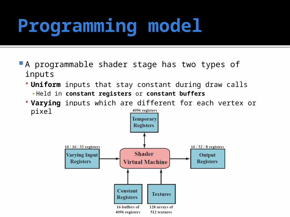
Programming model
A programmable shader stage has two types of inputs Uniform inputs that stay constant during draw calls▪ Held in constant registers or constant buffers
Varying inputs which are different for each vertex or pixel
Language style
Fast operations: scalar and vector multiplications, additions, and combinations
Well-supported (and still relatively fast): reciprocal, square root, trig functions, exponentiation and log
Standard operations apply: + and * Other operations come through intrinsic
functions that do not require headers or libraries: atan(), dot(), log()
Flow control is done through "normal" if, switch, while, and for (but long loops are unusual)

Where the idea comes from In 1984, Cook came up with the idea of shade
trees, a series of operations used to color a pixel This example shows what the shader language
equivalent of the shade tree is
Shaders
There are three shaders you can program Vertex shader
Useful, but boring, mostly about doing transforms and getting normals
Geometry shader Optional, allows you to create vertices from
nowhere in hardware Pixel shader
Where all the color data gets decided on Also where we'll focus
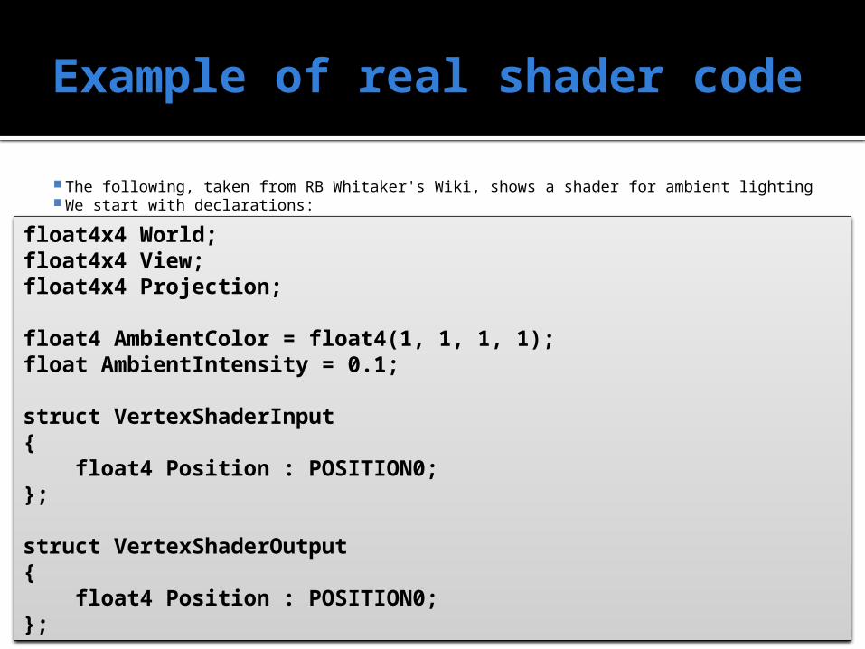
Example of real shader code
The following, taken from RB Whitaker's Wiki, shows a shader for ambient lighting We start with declarations:
float4x4 World;float4x4 View;float4x4 Projection;
float4 AmbientColor = float4(1, 1, 1, 1);float AmbientIntensity = 0.1;
struct VertexShaderInput{ float4 Position : POSITION0;};
struct VertexShaderOutput{ float4 Position : POSITION0;};
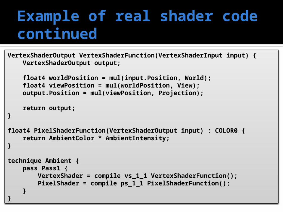
Example of real shader code continued
VertexShaderOutput VertexShaderFunction(VertexShaderInput input) { VertexShaderOutput output;
float4 worldPosition = mul(input.Position, World); float4 viewPosition = mul(worldPosition, View); output.Position = mul(viewPosition, Projection);
return output;}
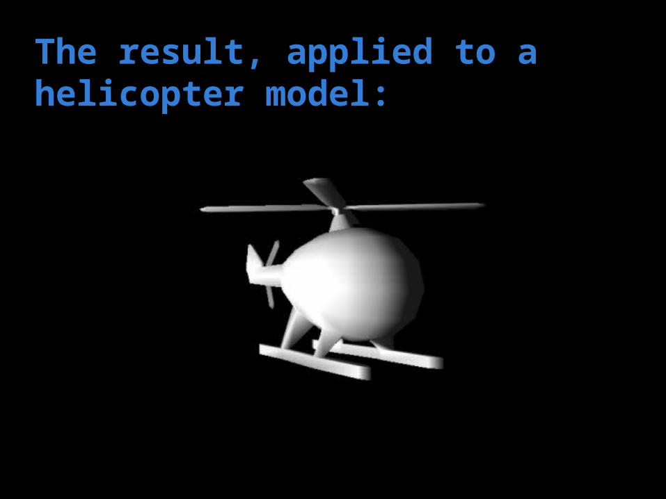
float4 PixelShaderFunction(VertexShaderOutput input) : COLOR0 { return AmbientColor * AmbientIntensity;}
technique Ambient { pass Pass1 { VertexShader = compile vs_1_1 VertexShaderFunction(); PixelShader = compile ps_1_1 PixelShaderFunction(); }}
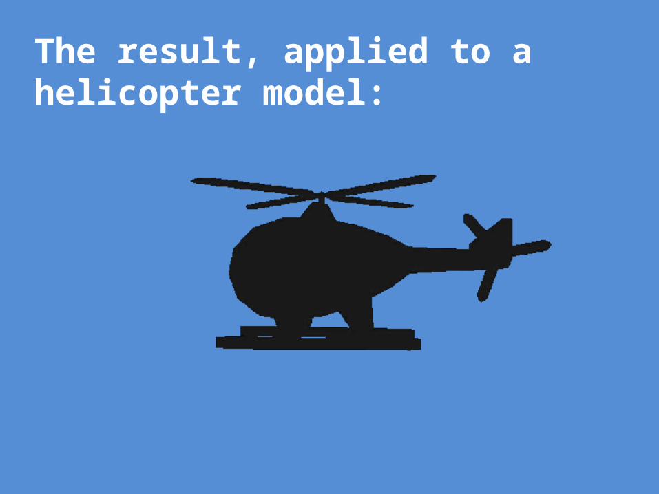
The result, applied to a helicopter model:
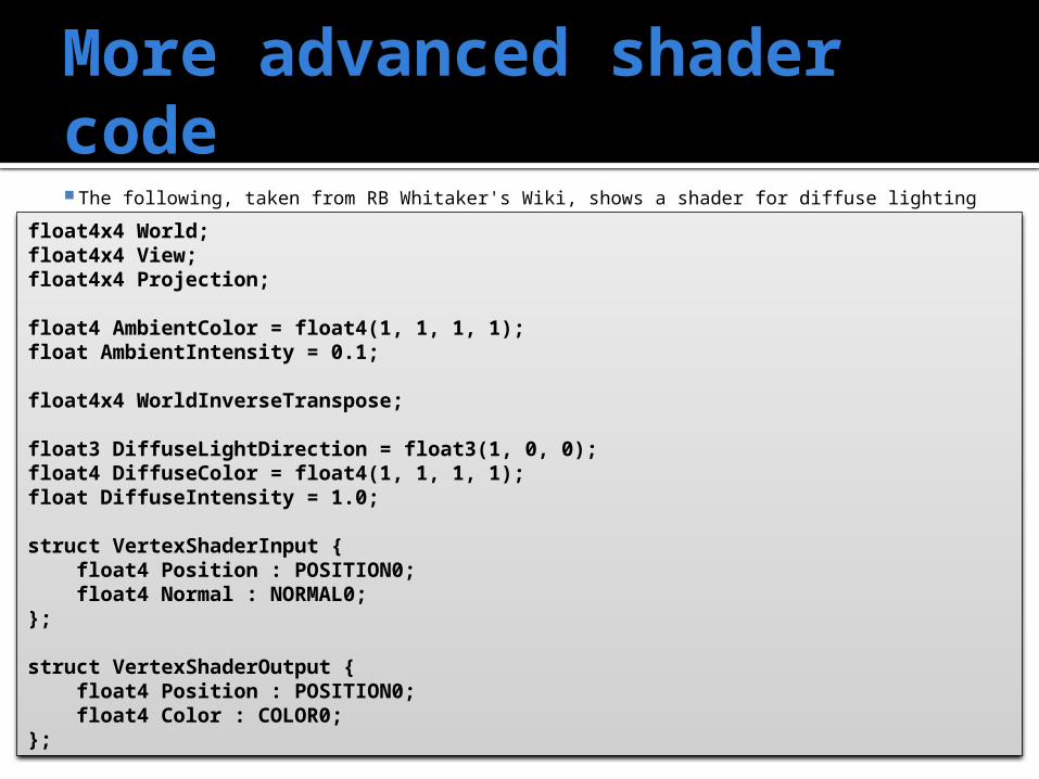
More advanced shader code The following, taken from RB Whitaker's Wiki, shows a shader for diffuse lighting
float4x4 World;float4x4 View;float4x4 Projection;
float4 AmbientColor = float4(1, 1, 1, 1);float AmbientIntensity = 0.1;
float4x4 WorldInverseTranspose;
float3 DiffuseLightDirection = float3(1, 0, 0);float4 DiffuseColor = float4(1, 1, 1, 1);float DiffuseIntensity = 1.0;
struct VertexShaderInput { float4 Position : POSITION0; float4 Normal : NORMAL0;};
struct VertexShaderOutput { float4 Position : POSITION0; float4 Color : COLOR0;};
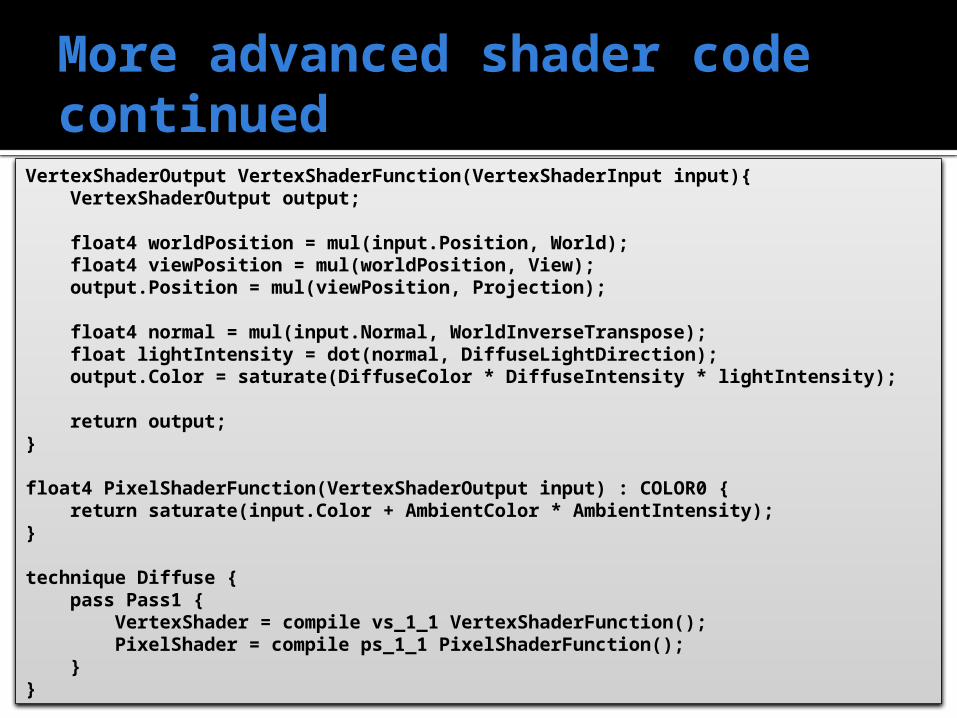
More advanced shader code continued
VertexShaderOutput VertexShaderFunction(VertexShaderInput input){ VertexShaderOutput output;
float4 worldPosition = mul(input.Position, World); float4 viewPosition = mul(worldPosition, View); output.Position = mul(viewPosition, Projection);
float4 normal = mul(input.Normal, WorldInverseTranspose); float lightIntensity = dot(normal, DiffuseLightDirection); output.Color = saturate(DiffuseColor * DiffuseIntensity * lightIntensity);
return output;}
float4 PixelShaderFunction(VertexShaderOutput input) : COLOR0 { return saturate(input.Color + AmbientColor * AmbientIntensity);}
technique Diffuse { pass Pass1 { VertexShader = compile vs_1_1 VertexShaderFunction(); PixelShader = compile ps_1_1 PixelShaderFunction(); }}
The result, applied to a helicopter model:
Vertex Shading
Vertex shader
Supported in hardware by all modern GPUs For each vertex, it modifies, creates, or ignores:
Color Normal Texture coordinates Position
It must also transform vertices from model space to homogeneous clip space
Vertices cannot be created or destroyed, and results cannot be passed from vertex to vertex Massive parallelism is possible
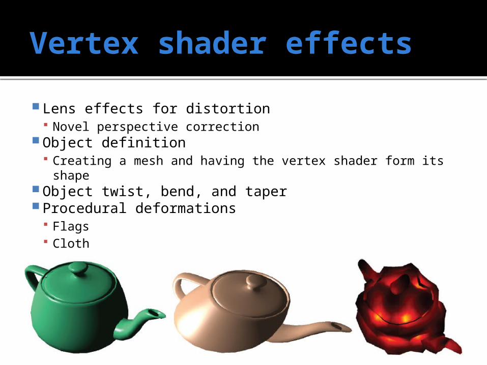
Vertex shader effects
Lens effects for distortion Novel perspective correction
Object definition Creating a mesh and having the vertex shader form its shape
Object twist, bend, and taper Procedural deformations
Flags Cloth Water
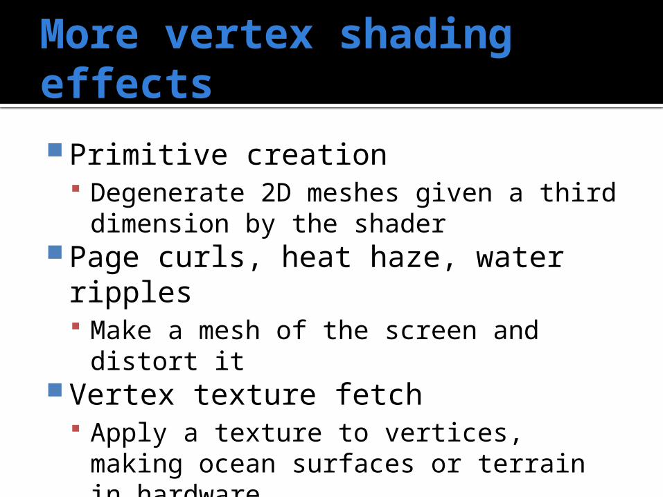
More vertex shading effects
Primitive creation Degenerate 2D meshes given a third
dimension by the shader Page curls, heat haze, water ripples
Make a mesh of the screen and distort it Vertex texture fetch
Apply a texture to vertices, making ocean surfaces or terrain in hardware
Geometry Shading
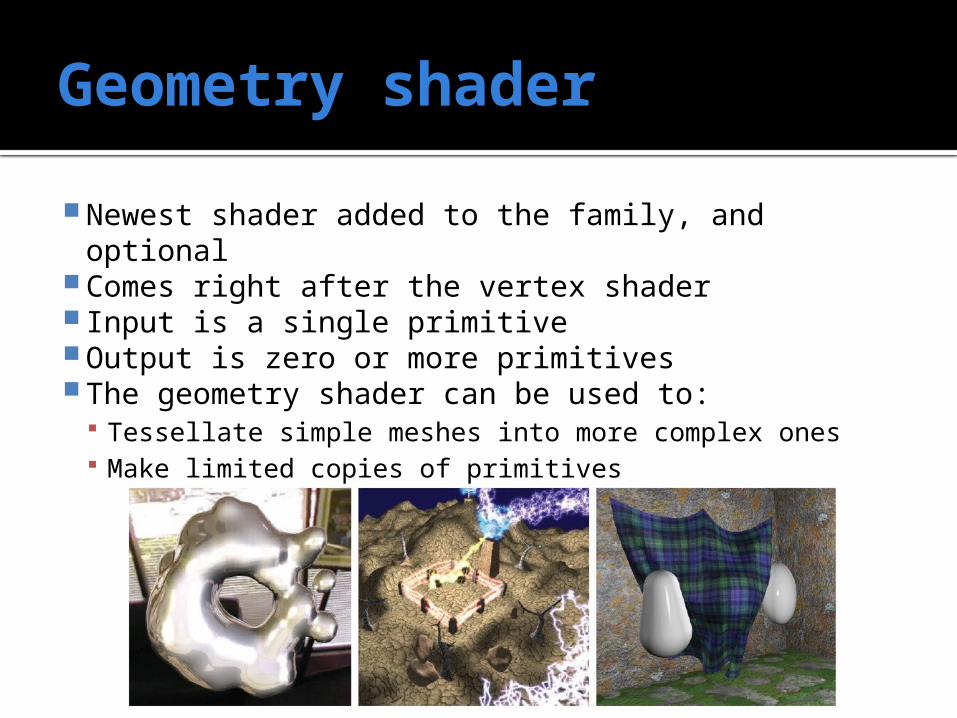
Geometry shader
Newest shader added to the family, and optional Comes right after the vertex shader Input is a single primitive Output is zero or more primitives The geometry shader can be used to:
Tessellate simple meshes into more complex ones Make limited copies of primitives
Stream output
The geometry shader is guaranteed to return output in the same order as the input was received
In Shader Model 4.0 and later, the output of the GS can be put into a stream (an ordered array)
This stream can be rasterized or it can be sent back through the pipeline for multi-step effects
For computational purposes, the stream could simply be output non-graphically
Pixel Shading
Pixel shader
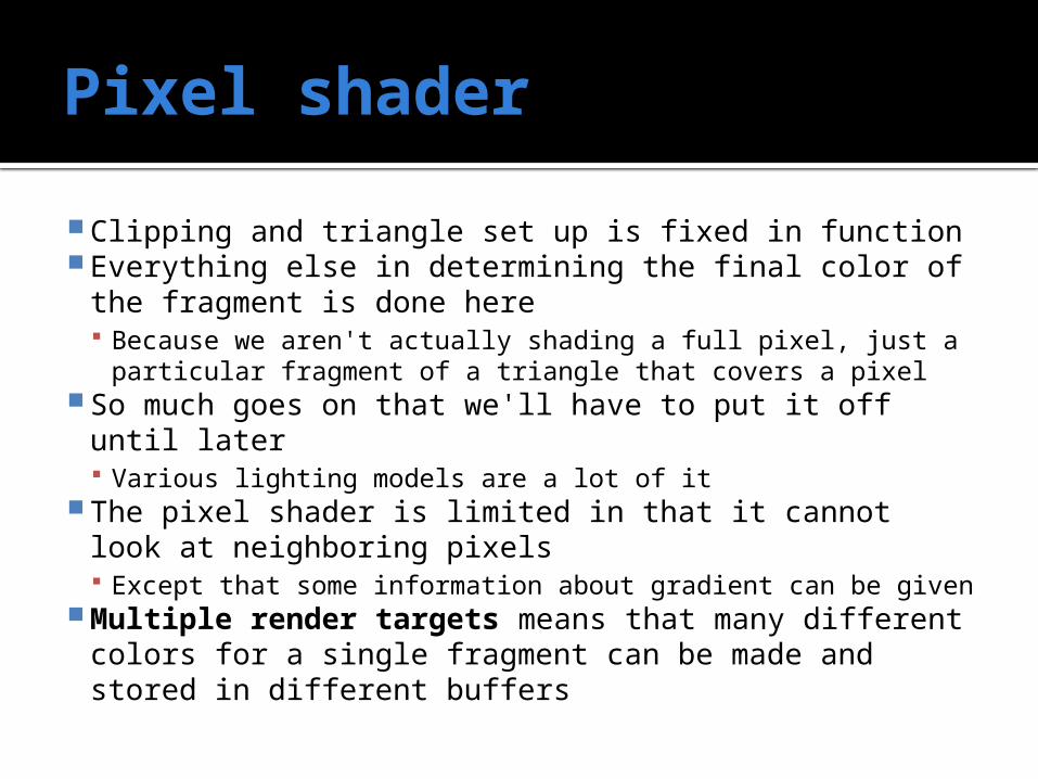
Clipping and triangle set up is fixed in function Everything else in determining the final color of the
fragment is done here Because we aren't actually shading a full pixel, just a
particular fragment of a triangle that covers a pixel So much goes on that we'll have to put it off until later
Various lighting models are a lot of it The pixel shader is limited in that it cannot look at
neighboring pixels Except that some information about gradient can be given
Multiple render targets means that many different colors for a single fragment can be made and stored in different buffers
Merging Stage
Merging stage
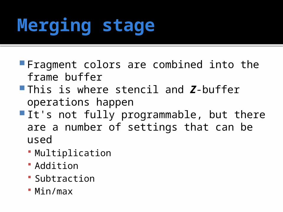
Fragment colors are combined into the frame buffer
This is where stencil and Z-buffer operations happen
It's not fully programmable, but there are a number of settings that can be used Multiplication Addition Subtraction Min/max
Effects
All this programming gets complicated…
So, people in the industry have tried to collect useful programs for rendering things
A collection of shaders to achieve a particular rendering effect can be stored in an effect file (commonly with extension .fx)
The syntax of the effects language allows your application to set specific arguments
Tools to generate effects
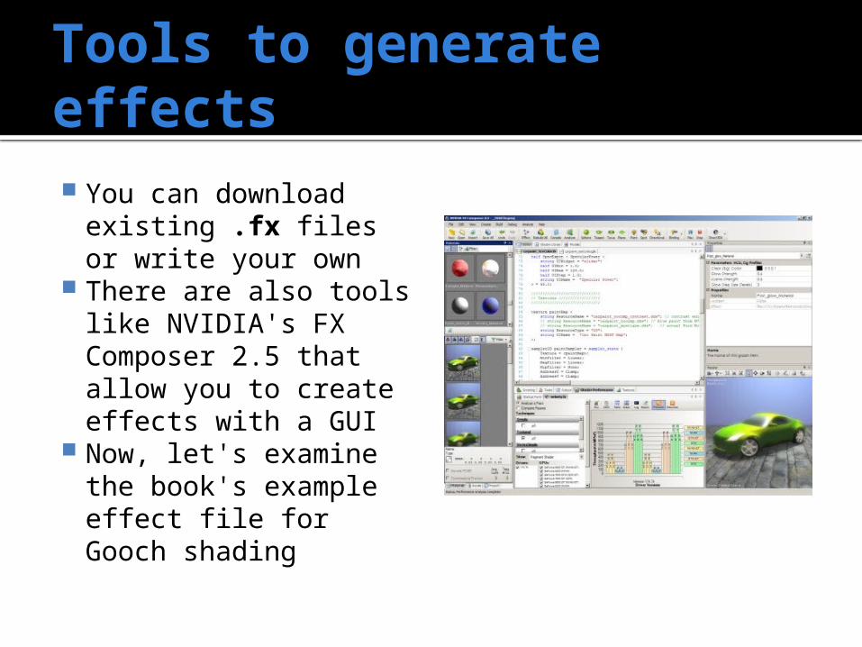
You can download existing .fx files or write your own
There are also tools like NVIDIA's FX Composer 2.5 that allow you to create effects with a GUI
Now, let's examine the book's example effect file for Gooch shading
Standard variables
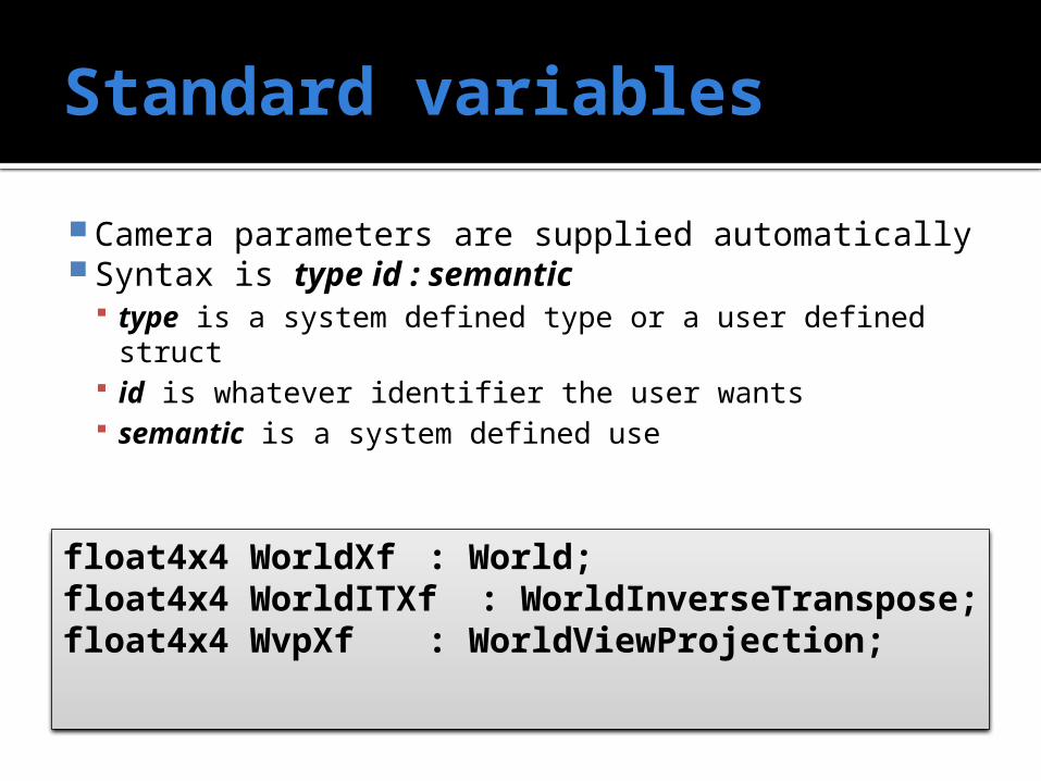
Camera parameters are supplied automatically Syntax is type id : semantic
type is a system defined type or a user defined struct id is whatever identifier the user wants semantic is a system defined use
float4x4 WorldXf : World;float4x4 WorldITXf : WorldInverseTranspose;float4x4 WvpXf : WorldViewProjection;
User variables
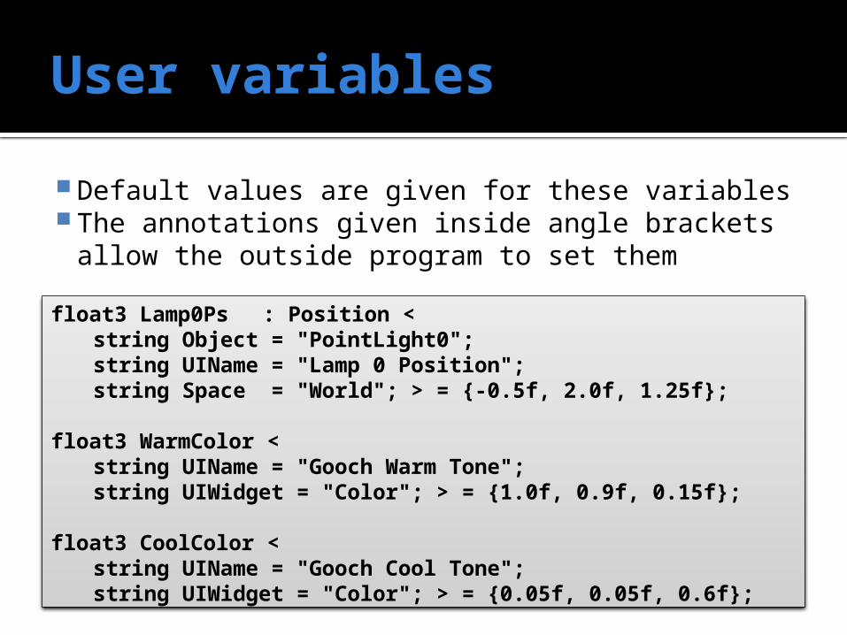
Default values are given for these variables The annotations given inside angle brackets
allow the outside program to set themfloat3 Lamp0Ps : Position <
string Object = "PointLight0";string UIName = "Lamp 0 Position";string Space = "World"; > = {-0.5f, 2.0f, 1.25f};
float3 WarmColor < string UIName = "Gooch Warm Tone";string UIWidget = "Color"; > = {1.0f, 0.9f, 0.15f};
float3 CoolColor < string UIName = "Gooch Cool Tone";string UIWidget = "Color"; > = {0.05f, 0.05f, 0.6f};
User defined structs
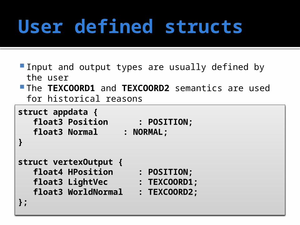
Input and output types are usually defined by the user The TEXCOORD1 and TEXCOORD2 semantics are used for
historical reasons
struct appdata {float3 Position : POSITION;float3 Normal : NORMAL;
}
struct vertexOutput {float4 HPosition : POSITION;float3 LightVec : TEXCOORD1;float3 WorldNormal : TEXCOORD2;
};
Vertex shader
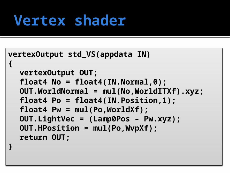
vertexOutput std_VS(appdata IN){
vertexOutput OUT;float4 No = float4(IN.Normal,0);OUT.WorldNormal = mul(No,WorldITXf).xyz;float4 Po = float4(IN.Position,1);float4 Pw = mul(Po,WorldXf);OUT.LightVec = (Lamp0Pos – Pw.xyz);OUT.HPosition = mul(Po,WvpXf);return OUT;
}
Pixel shader
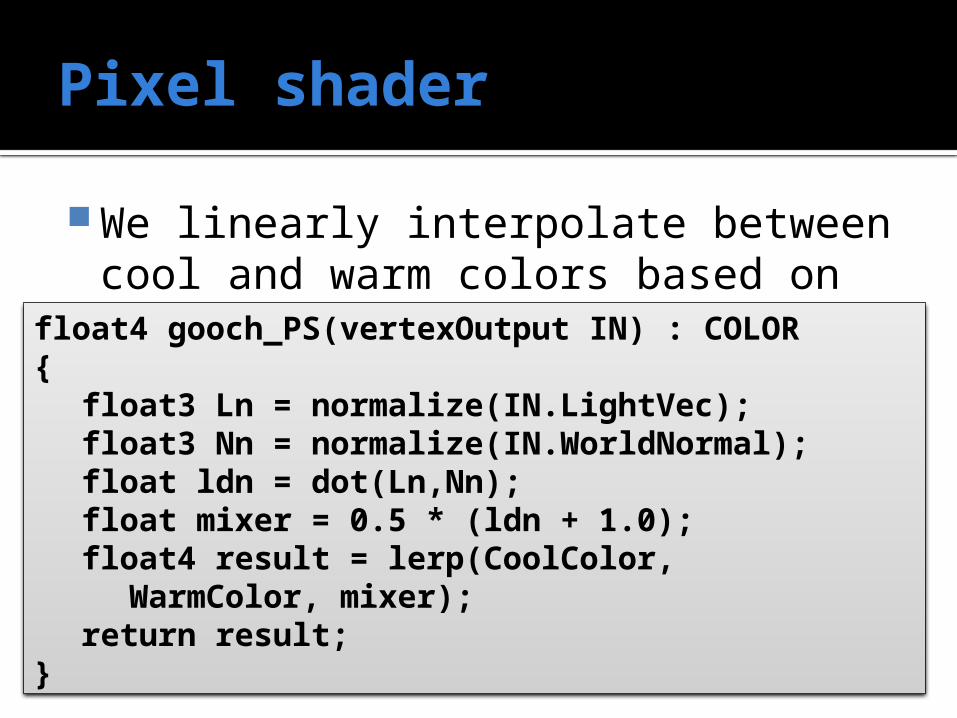
We linearly interpolate between cool and warm colors based on the dot productfloat4 gooch_PS(vertexOutput IN) : COLOR
{float3 Ln = normalize(IN.LightVec);float3 Nn = normalize(IN.WorldNormal);float ldn = dot(Ln,Nn);float mixer = 0.5 * (ldn + 1.0);float4 result = lerp(CoolColor,
WarmColor, mixer);return result;
}
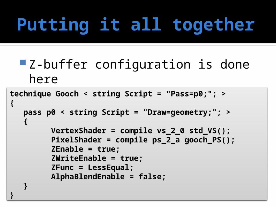
Putting it all together
Z-buffer configuration is done here
technique Gooch < string Script = "Pass=p0;"; >{
pass p0 < string Script = "Draw=geometry;"; > {
VertexShader = compile vs_2_0 std_VS();PixelShader = compile ps_2_a gooch_PS();ZEnable = true;ZWriteEnable = true;ZFunc = LessEqual;AlphaBlendEnable = false;
}}
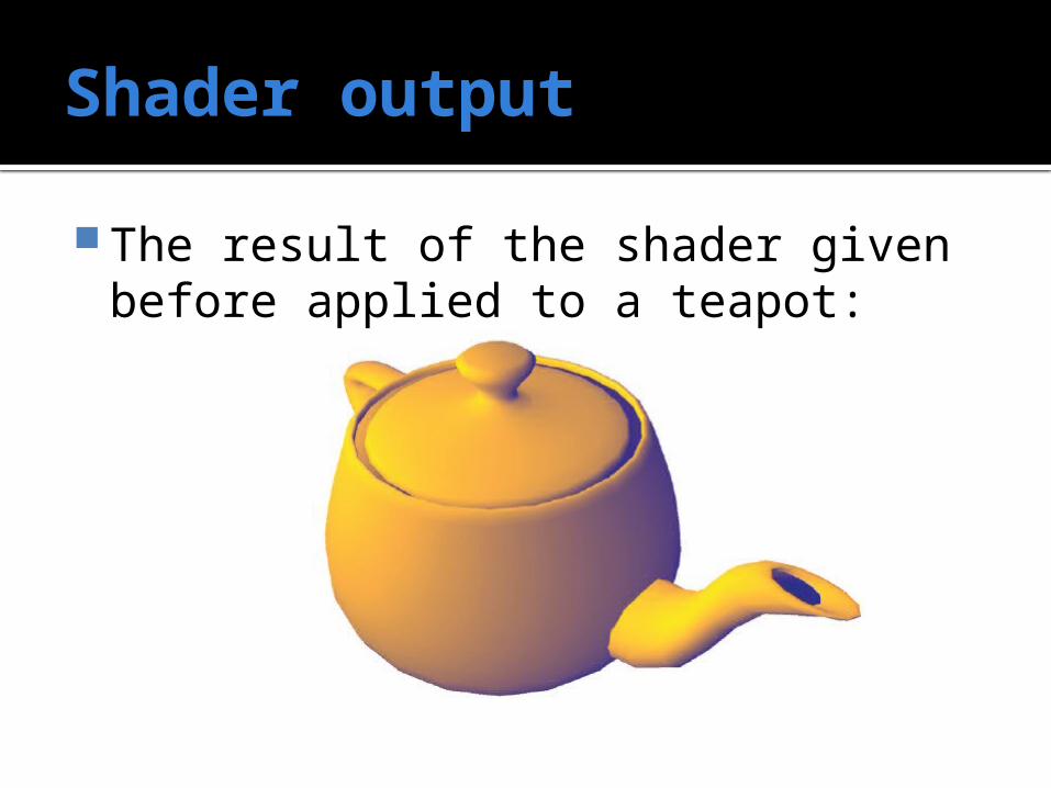
Shader output
The result of the shader given before applied to a teapot:
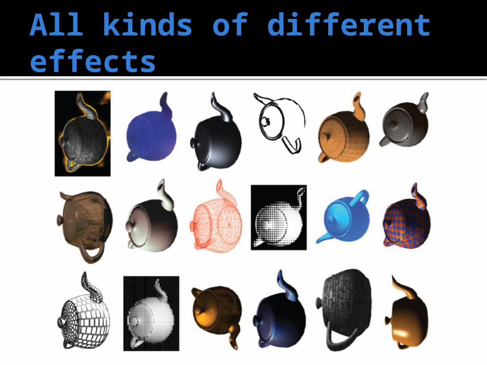
All kinds of different effects

Why a teapot?
The Utah teapot was modeled in 1975 by graphics pioneer Martin Newell at the University of Utah
It's actually taller than it looks They distorted the model so that it
would look right on their non-square pixel displays
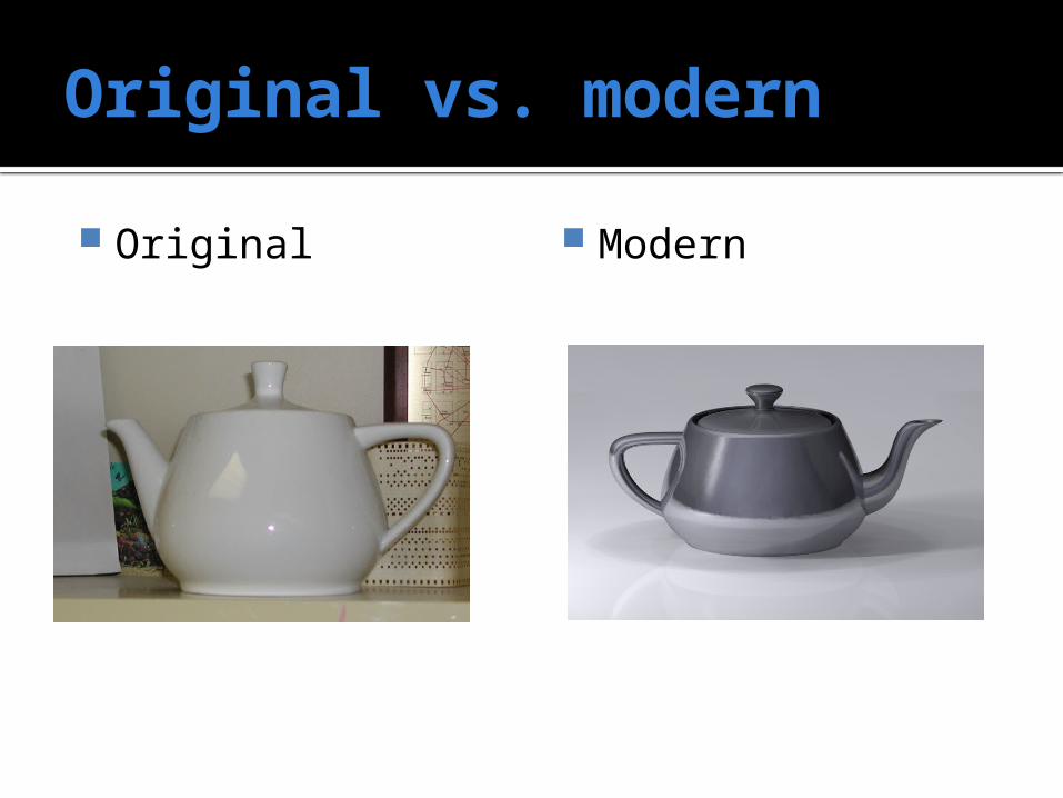
Original vs. modern
Original Modern
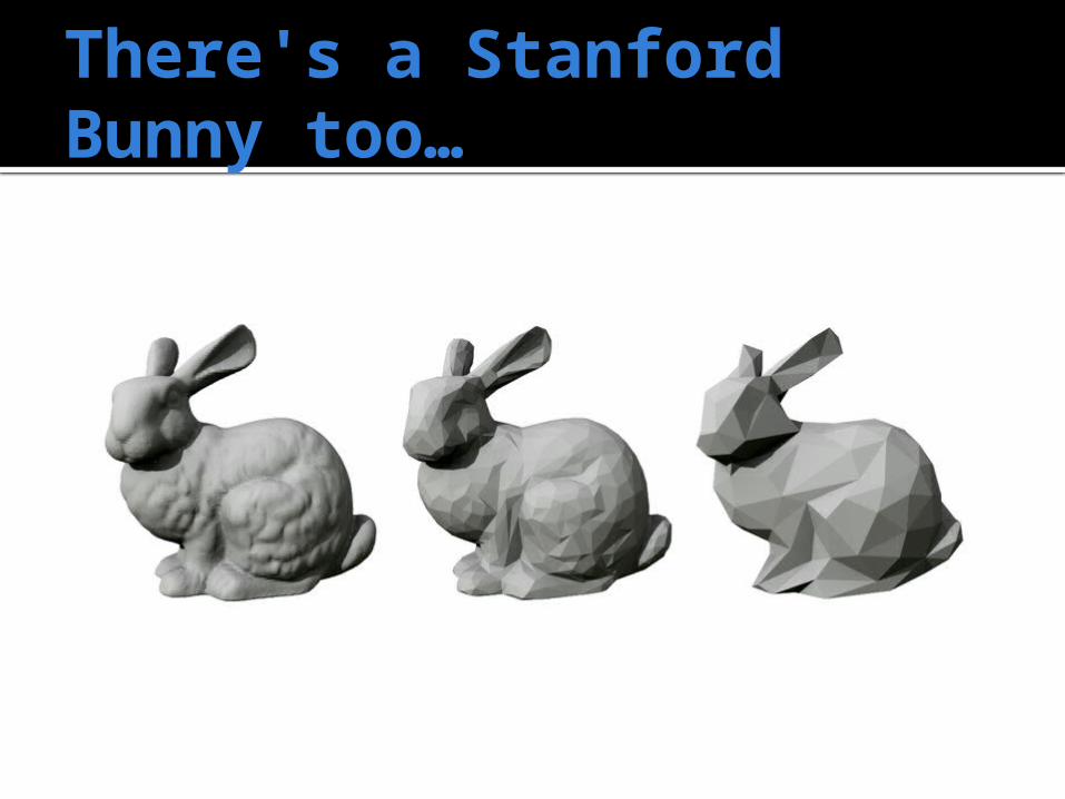
There's a Stanford Bunny too…
Quiz
Upcoming
Next time…
Linear algebra review Vectors and matrices
Reminders
Read Appendix A Finish Assignment 1, due Friday by
11:59 Keep working on Project 1, due
Friday, February 6 by 11:59