Embed Size (px)
Citation preview

Week 6 Exercises
Cameras
1. You are using a CCD camera and operating under conditions where dark noise and fixed pattern noise can be disregarded. The read noise is however 12 e RMS. Since your object is moving you can only integrate over a short period giving you an average signal of 10 counts. a) What is your signal to noise ratio? b) How many pixels would you need to binn to reach the photon shot noise limit? What will the
SNR be?
2. While working as an astronomer you want to image a faint star, “star 1”, with your CCD. Unfortunately it is pretty close to the bright “star 2” so that when star 2 saturates your CCD the blooming (charges spilling over from the saturated pixel to surrounding pixels) destroys the image of star 1. This limits the integration time you can use. In addition you have a background signal from light pollution from surrounding buildings. The background signal accumulates uniformly over the image. If star 2 gives a signal of 40 counts/s, star 1 20 counts/s and the background level is 30 counts/s what integration time should you use and what will be the best signal to noise ratio you can achieve. The full well depth of the camera is 16000 counts.
3. You have a CCD and a CMOS camera with the same pixel sizes but where the pixel fill factor is 0.95 for the CCD and 0.7 for the CMOS. a) Explain what the fill factor is and why it is lower for the CMOS camera. b) If you set the exposure times the same for both cameras. What impact do you think this will
have on the SNR at long integration times? Quantify!
Solar cells
1. At the back you have a spec sheet for a Suniva solar cell module consisting of 60 cells. Look at the module with power class 265W.
a) Consider the maximum voltage and current. How are the cells connected? b) What voltage do each cell contribute with? What current? c) What load should you use to get the maximum power out at 1 sun illumination (1000 W/m2)? d) If a cloud blocks the sun so that the illumination goes down to 400 W/m2 and the load resistance
isn’t changed what will the efficiency be then?
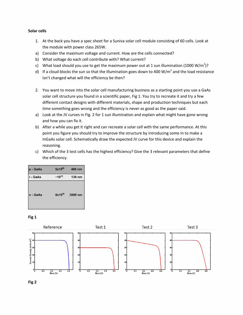
2. You want to move into the solar cell manufacturing business as a starting point you use a GaAs solar cell structure you found in a scientific paper, Fig 1. You try to recreate it and try a few different contact designs with different materials, shape and production techniques but each time something goes wrong and the efficiency is never as good as the paper said.
a) Look at the JV curves in Fig. 2 for 1 sun illumination and explain what might have gone wrong and how you can fix it.
b) After a while you get it right and can recreate a solar cell with the same performance. At this point you figure you should try to improve the structure by introducing some In to make a InGaAs solar cell. Schematically draw the expected JV curve for this device and explain the reasoning.
c) Which of the 3 test cells has the highest efficiency? Give the 3 relevant parameters that define the efficiency.
Fig 1
Fig 2

®
The Brilliance of Solar Made Sensible®
OUR PRODUCTS:
Monocrystalline Modules OPTIMUS SERIES 60 cell OPTIMUS SERIES 72 cell
Multicrystalline Modules MV SERIES 60 cell MV SERIES 72 cell
Monocrystalline Cells19%+ efficiency
Balance of Systems Solutions (BOSS)Racking, Inverters, Batteries, Energy Storage Appliances and EV Chargers
Certifications:
OPTXXX-60-4-100 (60 CELL MODULE)
OPTIMUS SERIES: OPT 60 CELL MODULES
The Optimus® modules consist of Suniva’s latest technology: ARTisun® Select. These superior monocrystalline cells are designed and manufactured in the U.S.A. using our proprietary low-cost processing techniques. Engineered with our pioneering ion implantation technology, high power-density Optimus modules provide excellent value, performance and reliability.
Engineering Excellence• Built exclusively with Suniva’s
highest-efficiency ARTisun Select cells, providing one of the highest power outputs per square meter at an affordable manufacturing cost
• Suniva’s state-of-the art manufacturing facility features the most advanced equipment and technology
• Suniva is a U.S. –based company spun out from the Georgia Tech University Center of Excellence in Photovoltaics (one of only two such research centers in the U.S.)
Features• Contains the latest ARTisun Select
cell technology - over 19%• Positive only power tolerance
ensures predictable output • Marine grade aluminum frame with
hard anodized coating• Industry leading linear warranty
(10 year warranty on workmanship and materials; 25 year linear performance warranty delivering 80% power at STC)
• Buy America compliant upon request• Qualifies for U.S. EXIM financing• System and design services available
Quality & ReliabilitySuniva Optimus modules are manufactured and warranted to our specifications assuring consistent high performance and quality worldwide. • Rigorous quality management• Performance longevity with
advanced polymer backsheet• Produced in an ISO 9001: 2008
certified facility • Passed the most stringent salt spray
test (Severity 6) based on IEC 61701• Passed enhanced stress tests1 based on
IEC 61215 conducted at Fraunhofer ISE2
• Certified PID free2
• Ask about our validated PAN files
SUNIVA OPTIMUS® SERIES MONOCRYSTALLINE SOLAR MODULES
High-quality and high-efficiency PV yields sensible solar

Please recycle.
Headquarters 5765 Peachtree Industrial Blvd., Norcross, Georgia 30092 USA Tel: +1 404 477 2700
www.suniva.com
®
The Brilliance of Solar Made Sensible®
08 09 12
0.0
1.0
2.0
3.0
4.0
5.0
6.0
7.0
8.0
9.0
10.0
0.0 5.0 10.0 15.0 20.0 25.0 30.0 35.0 40.0
Curr
ent (
A)
Voltage (V)
Suniva OPT265: 265 Watt, 60 Cell Solar Module Current-Voltage (IV) as a Function of Insolation
(W/m2) and Temperature
1000 W/m2 800 W/m2 600 W/m2 400 W/m2 200 W/m2 1000 W/m2 @ 50 C
TITLE
DWG NO.SIZE REV
SCALE SHEET
A
www2xx-60-c-1yy-zzzz S002PV Module Drawing
REV INCORP BY CHECKEDREVISION HISTORY
DESCRIPTION DATE1 J. O'Neill JODrawing for module design S002 6.1.11
Mounting Hole
Grounding Hole
Voltage ß, Voc (%/°C) -0.335Current α, Isc (%/°C) +0.047Power γ, Pmax (%/°C) -0.450NOCT Avg (+/- 2 °C) 46.0
The electrical data apply to standard test conditions (STC): Irradiance of 1000 W/m2 with AM 1.5 spectra at 25°C.
Cells / Module 60 (6x10)Module Dimensions 1653 x 982 mm (65.08 x 38.66 in.) Module Thickness (Depth) 46 mm (1.81 in.) Approximate Weight 18.69 kg (41.22 lbs.)
Max. System Voltage 1000 VDC for IEC (600 VDC for UL) Operating Module Temperature -40°C to +85°C Storm Resistance/Static Load Tested to IEC 61215 for loads up to 5400 Pa; hail and wind
resistant
The rated power may only vary by -0/+4.99Wp and all other electrical parameters by ± 5%
Suniva® reserves the right to change the data at any time. View manual at suniva.com. 1UV 90 kWh, TC 400, DH 2000. 2Tests were conducted on module type OPT 60. 3Tyco or MC4 - see sales representative.
Type of Solar Cell High-efficiency ARTisun® Select monocrystalline cells of 156 x 156 mm (6 in.)Frame Silver anodized aluminum alloy; black frame available by custom order Glass Tempered (low-iron), anti-reflective coatingJunction Box3 NEMA IP65 rated; 3 internal bypass diodes Cable & Connectors 4.0 mm2 cable with Tyco SolarLok connectors; cable length approximately 1000 mm Hardware (Available Upon Request)
Grounding screws: (2) #10-32 12.7 mm (#10-32 x 0.5 in.) Stainless steel flat washers: (4) 5 x 10 x 1 mm (0.2 in. ID x 0.394 in. OD x 0.030 in.)
OPTIMUS SERIES: OPT 60 CELL MODULES
Power Classification Pmax (W) 250 255 260 265Module efficiency % 15.40 15.71 16.02 16.33Model Number OPT 250-60-4-100 255-60-4-100 260-60-4-100 265-60-4-100Voltage at Max. Power Point Vmp (V) 29.60 30.00 30.20 30.70Current at Max. Power Point Imp (A) 8.44 8.50 8.60 8.64Open Circuit Voltage Voc (V) 37.70 37.90 38.10 38.30Short Circuit Current Isc (A) 8.98 9.05 9.08 9.12
Tolerances ± 1 mmHole Tolerances VaryDimensions in mm
ELECTRICAL DATA (NOMINAL)
DIMENSIONS AND WEIGHT
CHARACTERISTIC DATA
TEMPERATURE COEFFICIENTS
LIMITS