Embed Size (px)
Citation preview


Week Four Agenda• Attendance• Announcements• Review Week Three• Current Week Information• Upcoming Assignments
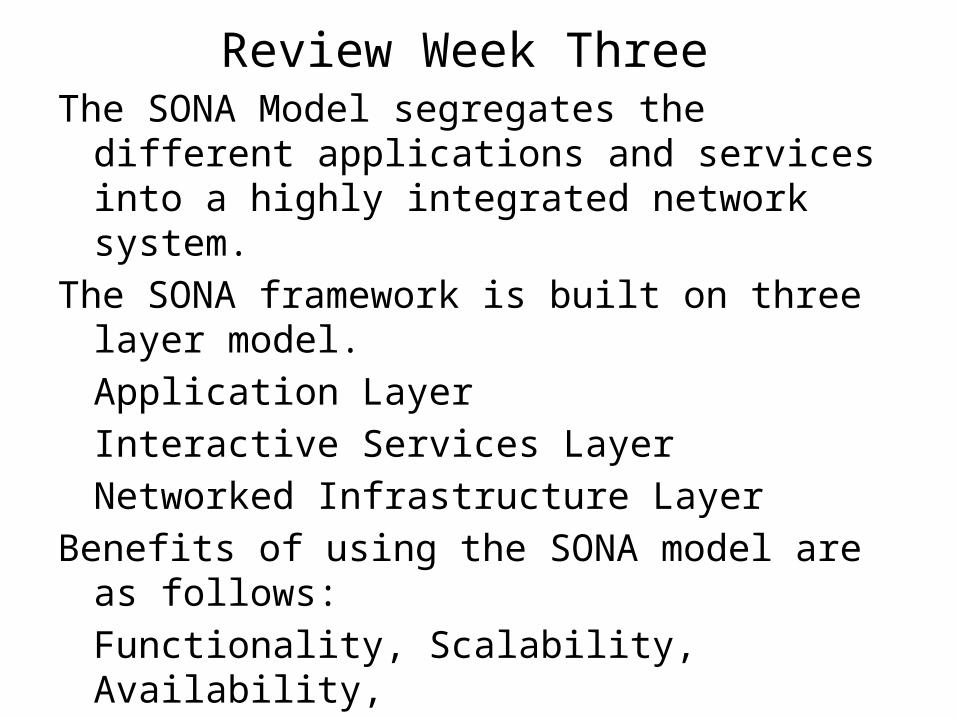
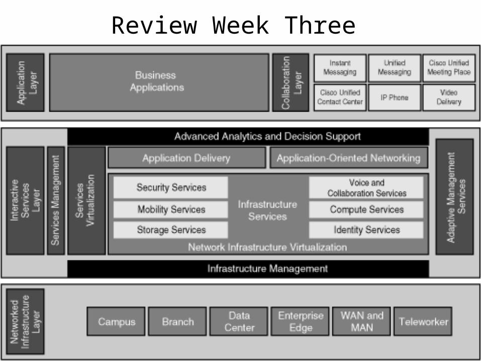
Review Week Three The SONA Model segregates the different applications
and services into a highly integrated network system.
The SONA framework is built on three layer model.
Application Layer
Interactive Services Layer
Networked Infrastructure Layer
Benefits of using the SONA model are as follows:
Functionality, Scalability, Availability,
Performance, and Manageability
Review Week Three
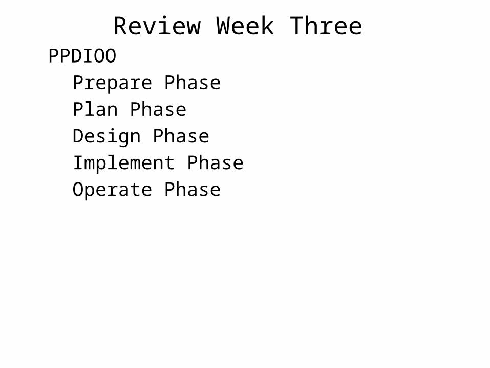
Review Week Three PPDIOO
Prepare Phase
Plan Phase
Design Phase
Implement Phase
Operate Phase
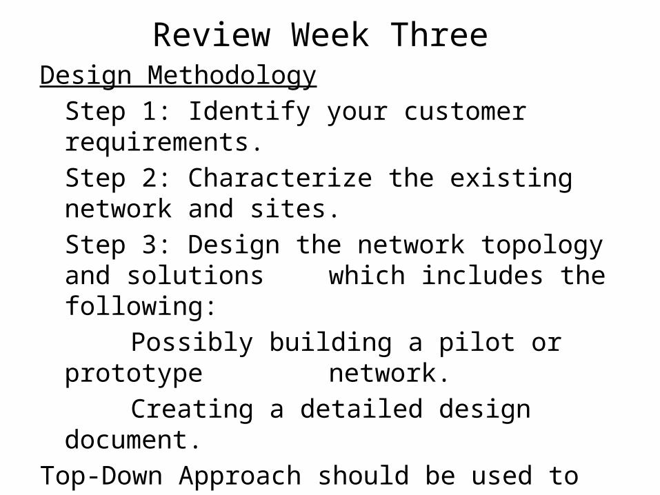
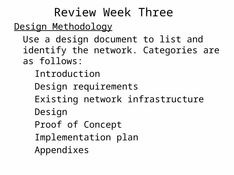
Review Week Three Design Methodology
Step 1: Identify your customer requirements.
Step 2: Characterize the existing network and sites.
Step 3: Design the network topology and solutions which includes the following:
Possibly building a pilot or prototype network.
Creating a detailed design document.
Top-Down Approach should be used to design a network solution, after the organizational requirements and documenting the existing network. This approach allows the designer to view the picture before worrying about the details.
Review Week Three Design Methodology
Use a design document to list and identify the network. Categories are as follows:
Introduction
Design requirements
Existing network infrastructure
Design
Proof of Concept
Implementation plan
Appendixes
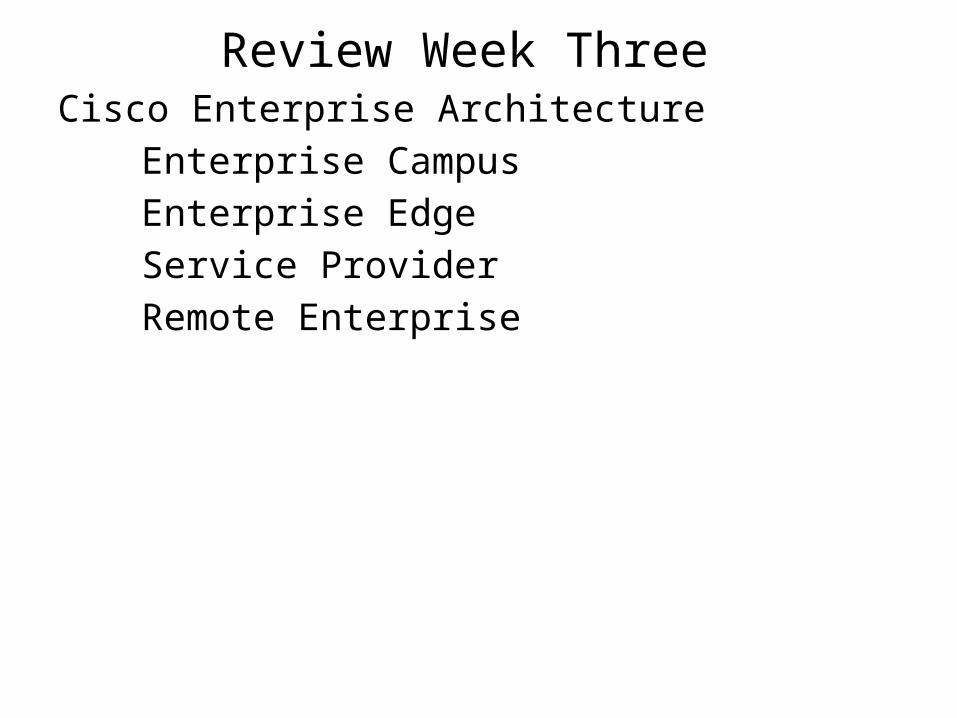
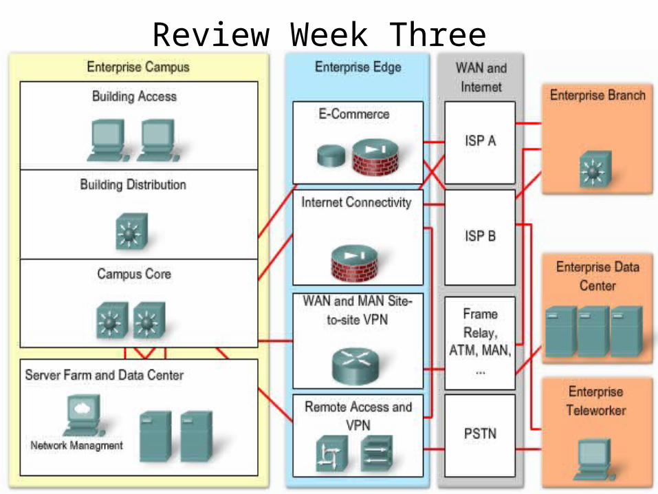
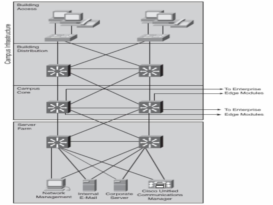
Review Week Three Cisco Enterprise Architecture
Enterprise Campus
Enterprise Edge
Service Provider
Remote Enterprise
Review Week Three
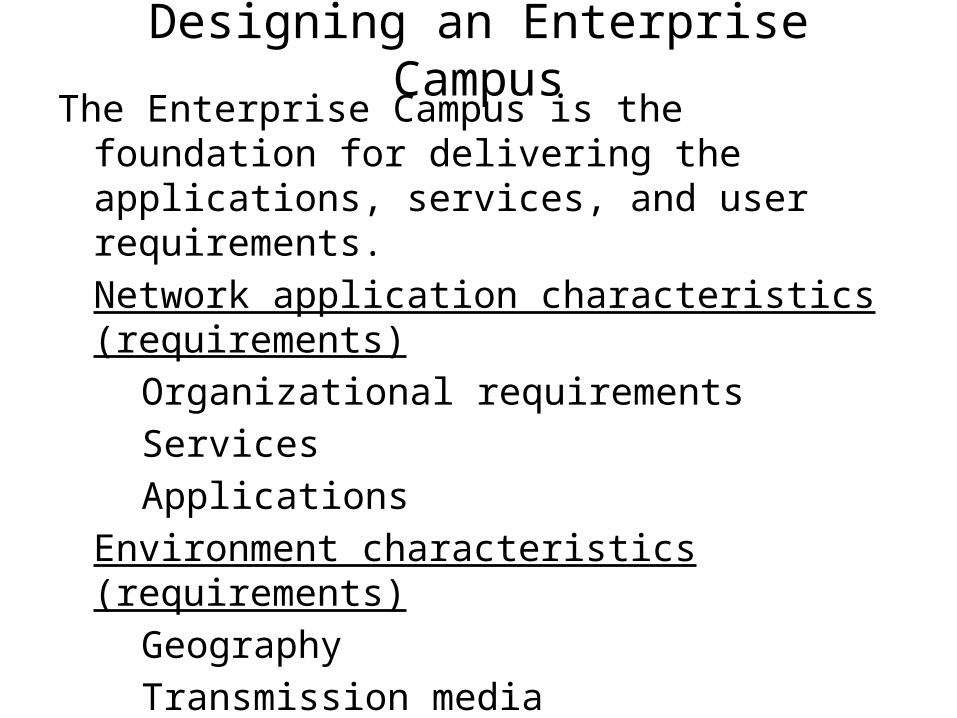
Designing an Enterprise CampusThe Enterprise Campus is the foundation for delivering
the applications, services, and user requirements.
Network application characteristics (requirements)
Organizational requirements
Services
Applications
Environment characteristics (requirements)
Geography
Transmission media
Infrastructure device characteristics (requirements)
High availability
High throughput
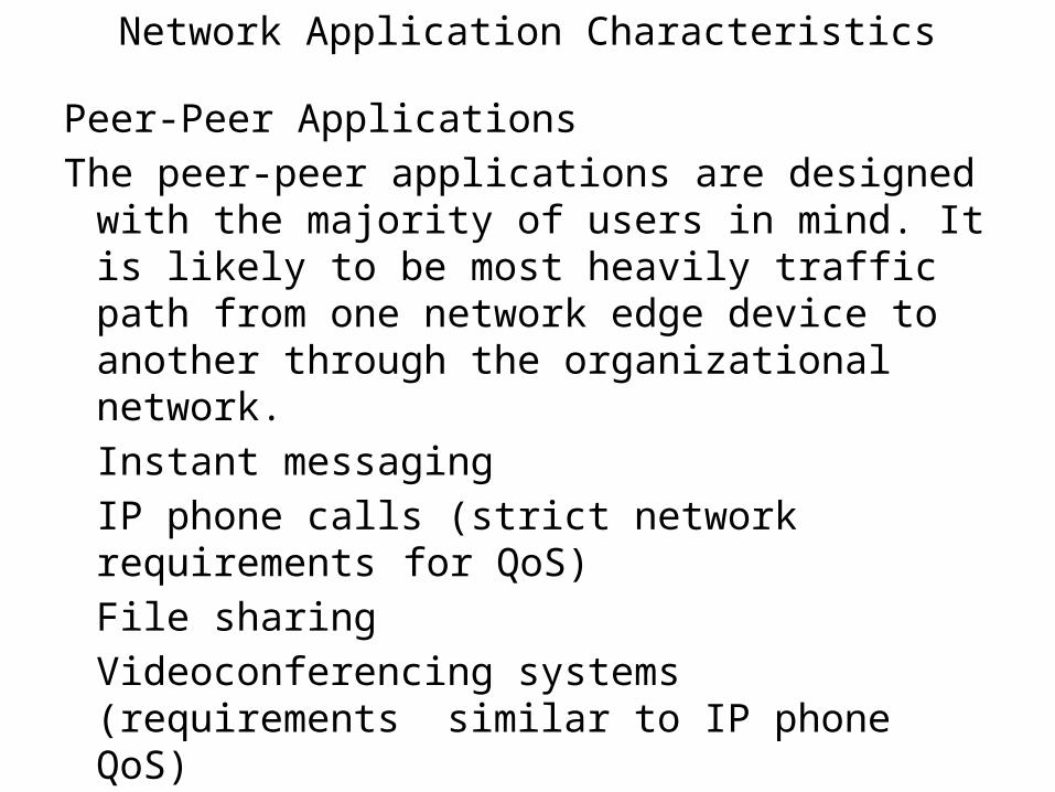
Network Application Characteristics
Peer-Peer Applications
The peer-peer applications are designed with the majority of users in mind. It is likely to be most heavily traffic path from one network edge device to another through the organizational network.
Instant messaging
IP phone calls (strict network requirements for QoS)
File sharing
Videoconferencing systems (requirements similar to IP phone QoS)
Network Application Characteristics
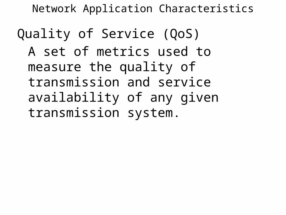
Quality of Service (QoS)
A set of metrics used to measure the quality of transmission and service availability of any given transmission system.
Network Application Characteristics
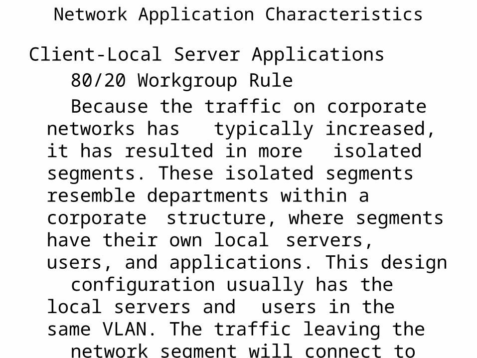
Client-Local Server Applications
80/20 Workgroup Rule
Because the traffic on corporate networks has typically increased, it has resulted in more
isolated segments. These isolated segments resemble departments within a corporate structure, where segments have their own local servers, users, and applications. This design configuration usually has the local servers and users in the same VLAN. The traffic leaving the network segment will connect to the campus backbone to connect to other VLANs or destinations.
Network Application Characteristics
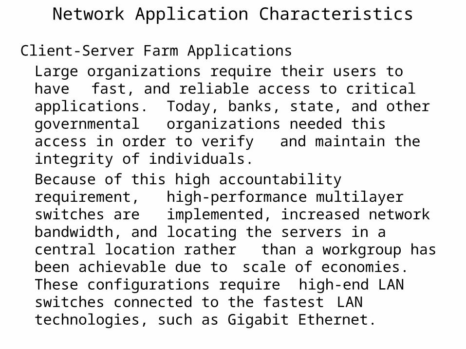
Client-Server Farm Applications
Large organizations require their users to have fast, and reliable access to critical applications. Today, banks, state, and other governmental organizations needed this access in order to
verify and maintain the integrity of individuals.
Because of this high accountability requirement, high-performance multilayer switches are
implemented, increased network bandwidth, and locating the servers in a central location rather than a workgroup has been achievable due to scale of economies. These configurations require high-end LAN switches connected to the fastest LAN technologies, such as Gigabit Ethernet.
Network Application Characteristics
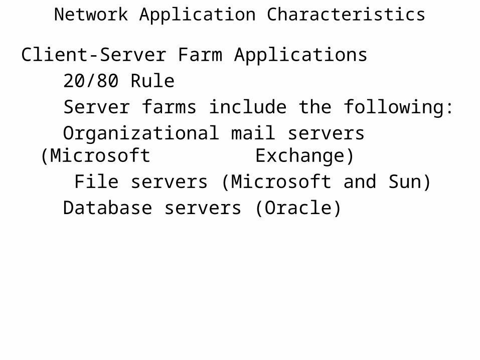
Client-Server Farm Applications
20/80 Rule
Server farms include the following:
Organizational mail servers (Microsoft Exchange)
File servers (Microsoft and Sun)
Database servers (Oracle)
Network Application Characteristics
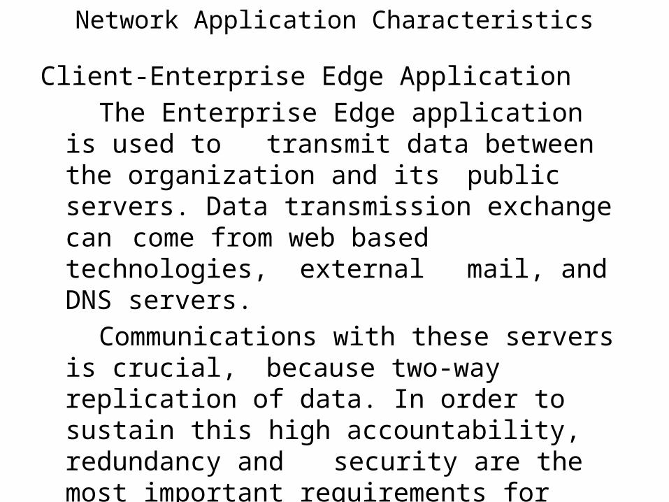
Client-Enterprise Edge Application
The Enterprise Edge application is used to transmit data between the organization and its public servers. Data transmission exchange can come from web based technologies, external mail, and DNS servers.
Communications with these servers is crucial, because two-way replication of data. In order
to sustain this high accountability, redundancy and security are the most important requirements for these applications.
Network Application Characteristics
Client-Enterprise Edge Application
Connectivity has increased the use of LAN switching at Layer 2. LAN switching has resulted in increased performance and more bandwidth for specific applications requirements of new organizational applications.
Throughput is the average rate of successful message delivery over a communication channel. This data may be delivered over a physical link, and/or pass through a certain network node. The throughput is usually measured in bits per second (bit/s or bps), and sometimes in data packets per second or data packets per time slot. Throughput varies between user workgroups and high capacity links to servers, and/or server farms.
Network Application Characteristics
Client-Enterprise Edge Application
High Availability is a function of the application and the entire network between the client
workstation and server(s) located in the network.
Summary
Project costs are driven by it’s size and applications used. If your implementing a peer-peer environment, normally the cost will be low. If your designing a network with redundancy and with high end application(s), your costs will be significantly higher. The types of applications used will also raise the cost

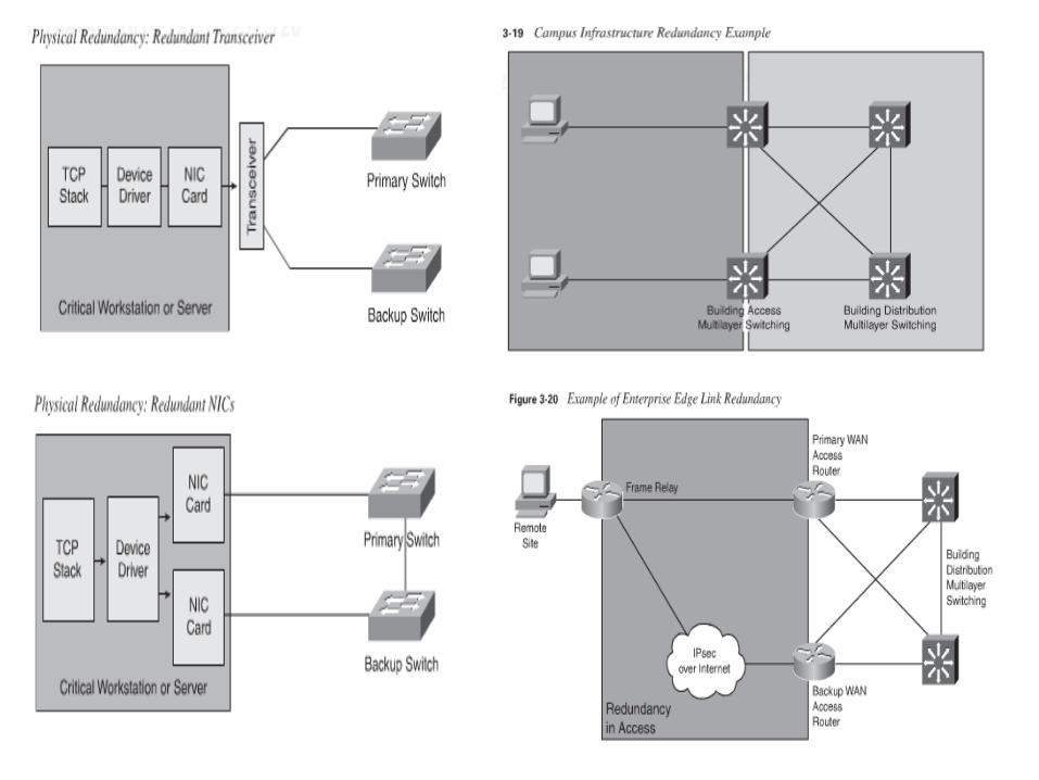
Environment CharacteristicsEnvironmental characteristics play a significant role in determining the location of the Enterprise Campus, the distance between buildings, the size and shapes of the buildings, and which technology to use to maximize the organizations investment.
Normally, the distance between nodes and their locations within an Enterprise Campus drive the type of technology utilized. In addition to the node (s) proximity, organizational requirements also influence the type of technology to be used. Users can’t just be connected to a network and be expected to tolerate data loss, access failures, poor performance, and intermittent connectivity problems.
Environment CharacteristicsStructural considerations within the network geography
Intrabuilding campus network structure provides connectivity for all terminating nodes located in the same building and provides external access to network resources. The Building Access and Building Distribution layers are located in the
same building.
User workstations are usually connected to the Building Access switches in the floor wiring closet with twisted-pair copper cable. Wireless technology can also be used to provide
connectivity within the building and/or between buildings without the use of UTP and cables.
Environment CharacteristicsStructural considerations within the network geography
The access layer switches connect to the Building Distribution switches over optical fiber.
This building configurations lend themselves to having a compressed hierarchical network where the Building Distribution switches and Campus Core switches are combined.
Environment CharacteristicsStructural considerations within the network geography
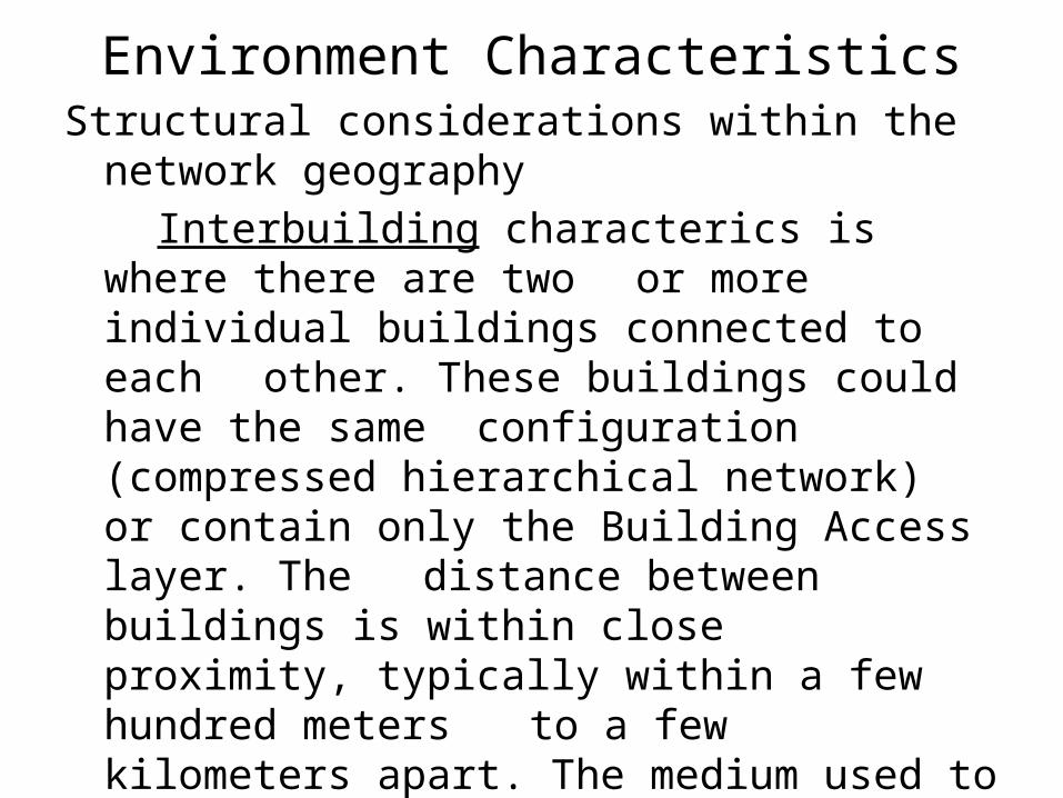
Interbuilding characterics is where there are two or more individual buildings connected to each
other. These buildings could have the same configuration (compressed hierarchical network) or contain only the Building Access layer. The distance between buildings is within close proximity, typically within a few hundred meters to a few kilometers apart. The medium used to interconnect campus buildings is normally customer owned, high-speed optical fiber.
Environment CharacteristicsStructural considerations within the network geography
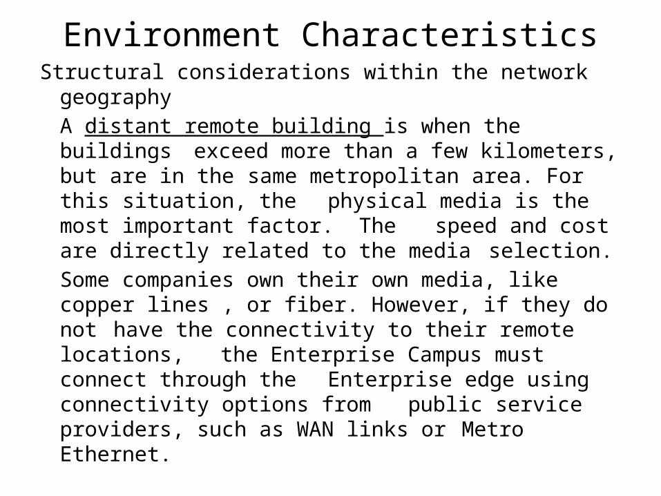
A distant remote building is when the buildings exceed more than a few kilometers, but are in
the same metropolitan area. For this situation, the physical media is the most important factor.
The speed and cost are directly related to the media selection.
Some companies own their own media, like copper lines , or fiber. However, if they do not have the connectivity to their remote locations, the Enterprise Campus must connect through the Enterprise edge using connectivity options from public service providers, such as WAN links or Metro Ethernet.
Environment CharacteristicsStructural considerations within the network geography
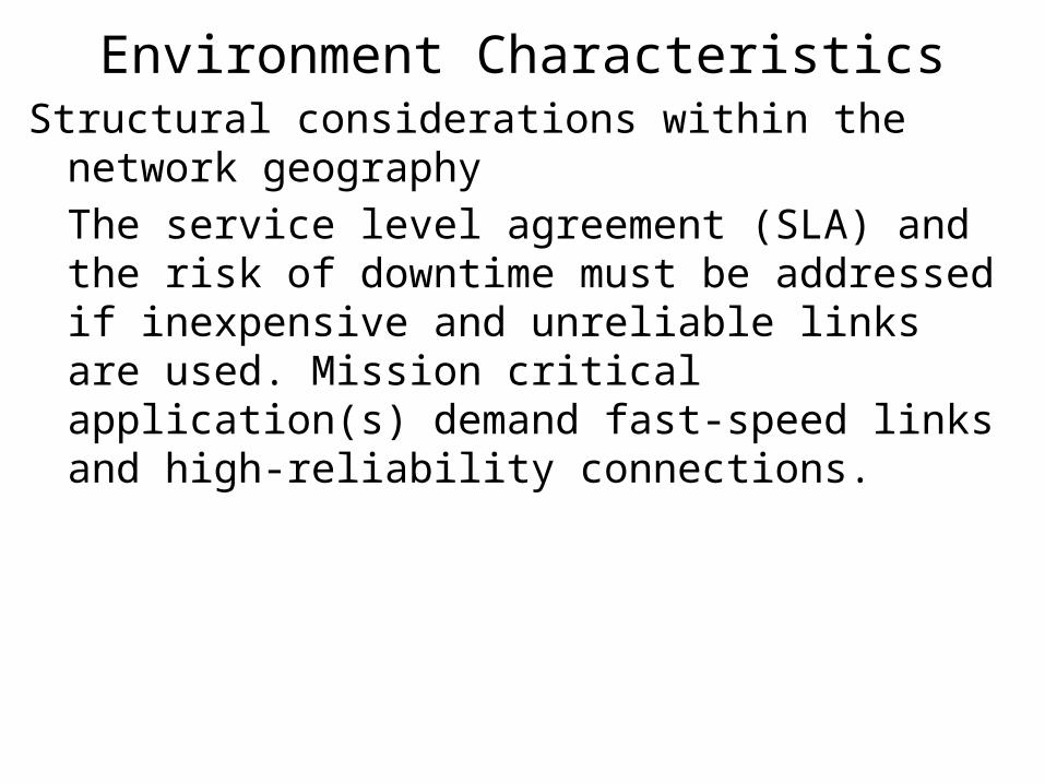
The service level agreement (SLA) and the risk of downtime must be addressed if inexpensive and unreliable links are used. Mission critical application(s) demand fast-speed links and high-reliability connections.
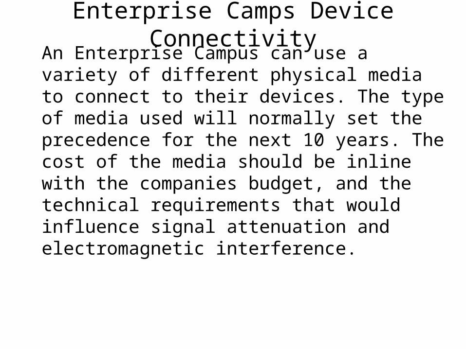
Enterprise Camps Device ConnectivityAn Enterprise Campus can use a variety of different physical media to connect to their devices. The type of media used will normally set the precedence for the next 10 years. The cost of the media should be inline with the companies budget, and the technical requirements that would influence signal attenuation and electromagnetic interference.
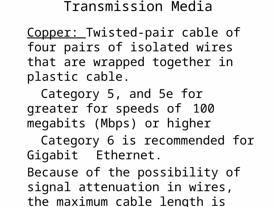
Transmission Media
Copper: Twisted-pair cable of four pairs of isolated wires that are wrapped together in plastic cable.
Category 5, and 5e for greater for speeds of 100 megabits (Mbps) or higher
Category 6 is recommended for Gigabit Ethernet.
Because of the possibility of signal attenuation in wires, the maximum cable length is usually 100 meters.
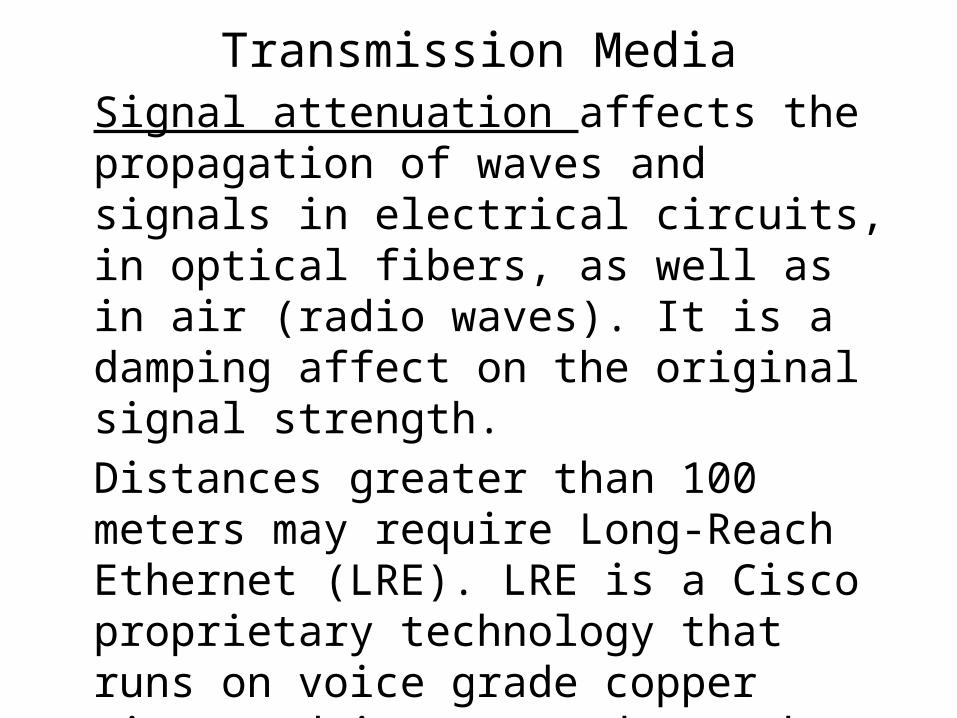
Transmission MediaSignal attenuation affects the propagation of waves and signals in electrical circuits, in optical fibers, as well as in air (radio waves). It is a damping affect on the original signal strength.
Distances greater than 100 meters may require Long-Reach Ethernet (LRE). LRE is a Cisco proprietary technology that runs on voice grade copper wire, and it accommodates the greater distance to access the technologies in WANs.
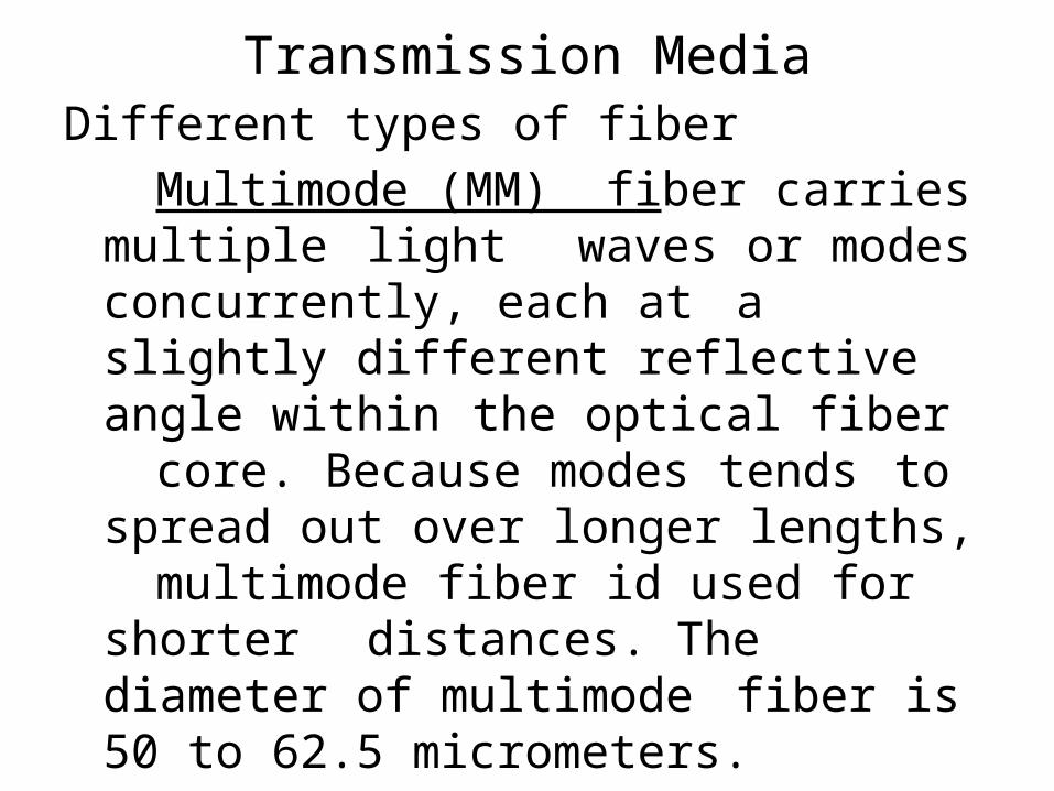
Transmission MediaDifferent types of fiber
Multimode (MM) fiber carries multiple light waves or modes concurrently, each
at a slightly different reflective angle within the optical fiber core. Because modes
tends to spread out over longer lengths, multimode fiber id used for shorter distances. The diameter of multimode
fiber is 50 to 62.5 micrometers.
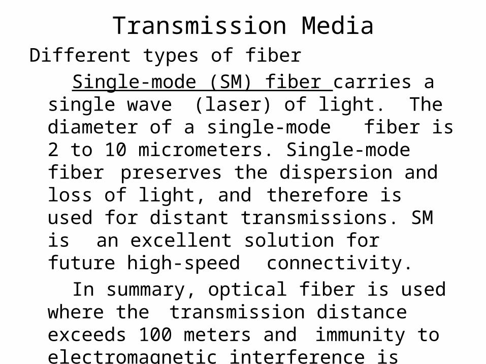
Transmission MediaDifferent types of fiber
Single-mode (SM) fiber carries a single wave (laser) of light. The diameter of a single-mode fiber is 2 to 10 micrometers. Single-mode fiber preserves the dispersion and loss of light, and therefore is used for distant transmissions. SM
is an excellent solution for future high-speed connectivity.
In summary, optical fiber is used where the transmission distance exceeds 100 meters and immunity to electromagnetic interference is required.
Transmission MediaWireless is also referred to as a radio receiver. The term refers to without cables or cords, chiefly using radio frequencies and inferred rays.
WLAN are useful when it comes to extending an existing network or replacing a traditional cabled network.
Inside buildings, the WLAN equipment includes an access point (AP), which acts similar to a wired hub, and PC client adapter.
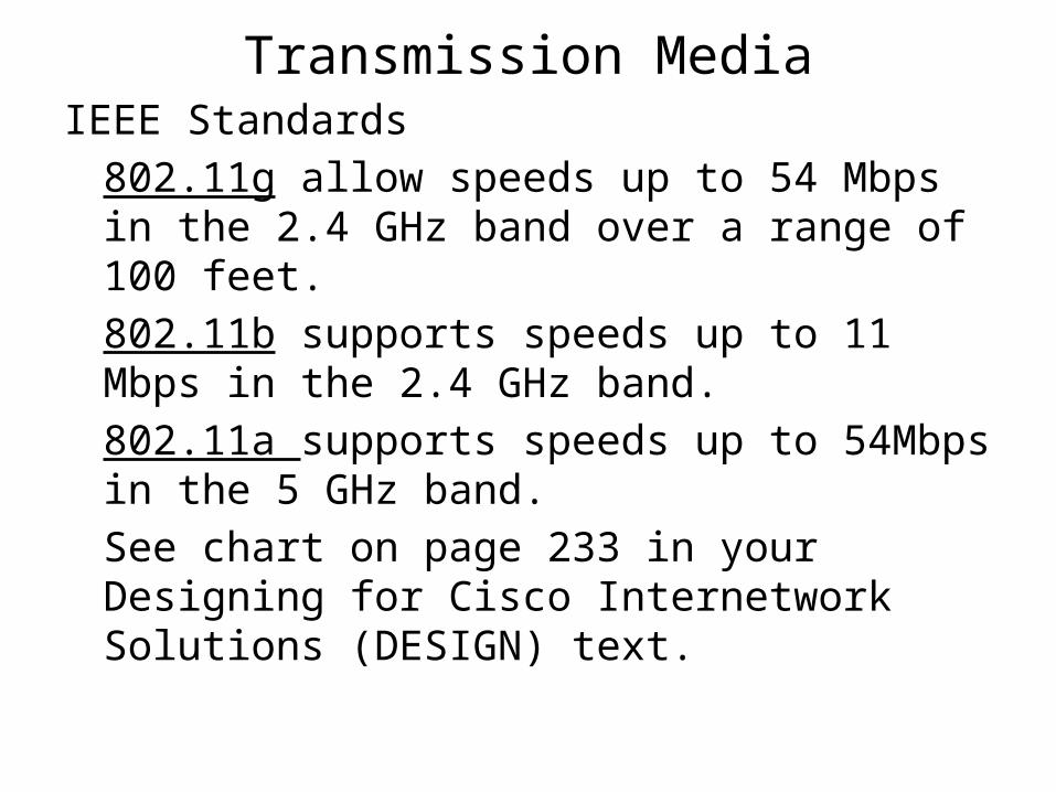
Transmission MediaIEEE Standards
802.11g allow speeds up to 54 Mbps in the 2.4 GHz band over a range of 100 feet.
802.11b supports speeds up to 11 Mbps in the 2.4 GHz band.
802.11a supports speeds up to 54Mbps in the 5 GHz band.
See chart on page 233 in your Designing for Cisco Internetwork Solutions (DESIGN) text.
Infrastructure Device CharacteristicsToday, most network end users are connected using switched technology and not shared media segment. The benefits of switched technology are dedicated network bandwidth for each device on the network. Switched networks also support infrastructure services, like QoS, security, and network management.LAN switches in the recent past were for Layer 2 devices. Now, Layer 2 switching supports multiple simultaneous frame flows. Multilayer switching performs packet switching and several functions at Layer 3 and higher up in the OSI layers. The technology is moving in the direction of replacing routers in the LAN switched environment.
Infrastructure Device CharacteristicsDifferences between Layer 2 and Multilayer
Switching
Multilayer switching provides different information inside the frame to determine the correct output interface.
Multilayer switching forwards frames based on network layer information rather than MAC address.
Multilayer switching is a hardware based switching and routing integrated into a single platform.
Infrastructure Device CharacteristicsConvergence time is the time it takes to update switching tables to reflect the actual network configuration. A loop prevention mechanism at Layer 2 topology called Spanning Tree Protocol (STP) took approximately 30 to 50 seconds to converge. Now the Campus Core links that were connecting to core switches should be routed links, and not VLAN trunks.Multilayer switching reduces convergence time to seconds, because all the devices detect their connected link failure immediately and act accordingly.
Infrastructure Device CharacteristicsMultilayer switching in a structured design reduces the scope of spanning-tree domains.
In a mixture of Layer 2 and Layer 3 environment, the convergence time depends on both layers, and the convergence of STP. Switching can also include Layer 4.
Multilayer switching allows switching to take place at different protocol layers.
Infrastructure Device CharacteristicsIP Multicast
IP multicast technology is a way to sending one data stream to multiple end users and maintain required bandwidth. The data stream is sent from one source, and replicated for the registered users at the destination.
Class D IP address ranges from 224.0.0.0 to 239.255.255.255.
Cisco Protocols for Routers and HostsInternet Group Management Protocol (IGMP)
The IGMP protocol is used between the router and the registered hosts intended to receive multicast data. The hosts notify the router to join or leave a specific multicast group.
Cisco Group Management Protocol (CGMP)
The CGMP protocol is used by switches and routers. The router informs the switches directly connected to them about the IGMP registration(s) from it’s hosts to receive multicast data stream.
Cisco Protocols for Routers and HostsInternet Control Message Protocol (ICMP) is
used by IP for many different services. ICMP is a management protocol and messaging service provider for IP. Its messages are carried as IP datagram's.
QoS ConsiderationsClassification and marking
Packet classification – partitioning traffic into multiple priority levels, or class of service
Marking – changing the frame priority or class of service
Congestion management
Queuing – separating traffic into different queues. The marking inside the frame or packet is used to determine which queue
Scheduling – is used to determine the order in which the queues are serviced
QoS ConsiderationsPolicing and shaping is a process of identifying
violations of threshold levels and reduces a stream of data to a predetermined rate or level. Traffic shaping buffers the frames for a short period of time. Policing drops or lowers the priority of the frame in violation.
Upcoming AssignmentsAssignment 4-1-1, Simulator Tutorial and Basic
IOS Command Exploration is due May 24, 2010
Assignment 5-1, Concept Question 4 is due May 31, 2010
Assignment 4-1-2, Basic Routing and LAN Switching Configuration is due June 28, 2010
Assignment 4-1-3, Basic Network Troubleshooting is due July 26, 2010