Embed Size (px)
Citation preview

Welcome, Friends! Welcome to the Newmar family… and what a family it is. Born on Christian principles, and from the desire to build not the most, but the best, the legacy associated with the name Newmar is one of family pride and quality. We take humble pride in our history of innovation. We introduced the industry to the first “slide out” rooms, and continued our tradition of innovation with the first slide out in a motorized RV, the “Flush Floor” slide out, and the smooth “seamless” fiberglass body. Your new King Aire is more than just another recreational vehicle. It is the culmination of decades of RV design and building experience. It is at the forefront of current technology, built by the skilled hands and quality conscious eyes of craftsmen. Here at Newmar, we recognize that a craftsman’s final product is only as good as the materials they use, so we are selective about what we put into our coaches. We start with a foundation forged in the strength of steel and aluminum. We fill it with beautiful, durable hardwoods, and select name brand appliances and components, then build it on chassis’ that are icons in the fire truck and RV industry because they stood the test of time. Then we hand finish our units with an artist’s gentle touch. It is important to us that you not just to enjoy your new unit but be proud of it, too. Your King Aire has been built to the highest standards we have ever set and attained. That’s why we back it with the best warranty in the industry. A heritage of quality and dependability make it easy for us to offer that kind of coverage. The Newmar King Aire proudly carries the Newmar torch into the new century, as a new generation of RV’ing begins. We share your excitement at this moment, and with you look forward to the years and miles of adventure the RV lifestyle offers you in your new King Aire. Whether camping at your favorite remote fishing hole or tailgating at the big game with your friends, have fun in the knowledge that Newmar is with you 24 hours a day, 7 days a week. Thank you again for your purchase of a King Aire, and welcome to the Newmar family. Newmar Corporation
2015 Newmar King Aire Diesel Bus 1

Chapter 1
GENERAL INFORMATION GENERAL INFORMATION ........................... 9
Taking Delivery of your new King Aire Dealer Responsibilities Customer Responsibilities Owner’s Information Package The Newmar Warranty on your new King Aire Warranty Service Deadline Customer Relations Reporting Safety Defects Owners Guide Information Placards and Labels Information Sheet / Appliance Data Label Weight Information
WEIGHING THE UNIT ............................... 13
GENERAL TIRE INFORMATION ................ 15 Tire Nomenclature Tire Inflation Information Tire Size
IMPORTANT RV TIRE INFORMATION ...... 16 READ AND UNDERSTAND THE FOLLOWING INFORMATION BEFORE TAKING YOUR FIRST TRIP IN YOUR RV!
CUSTOMER ASSISTANCE ....................... 17 COMPONENT PART SUPPLIES……………. 17
Chapter 2
GENERAL & SAFETY INFORMATION DRIVING AND SAFETY INFORMATION ..... 19
Before Driving Away Driving Dash Instrumentation and Controls Left Cluster Center Cluster Right Cluster Jacks Down Warning
2015 Newmar King Aire Diesel Bus 3

Antennae Up Warning Warning Lights and Signals Spartan Lightbar Message Center System Initialization Sequence Telltale Warning Light Information Spartan Smart Wheel Seat Memory Dash Switches Right Side Switches (above ignition switch) Left Side Dash Switches Drivers Side Console Switches Passenger Side Console Switches Headlamps and Parking Brake Power Seat Operation Rear Vision System Side View Cameras Trip Tek Monitoring System Sony In-Dash Stereo CD Changer Navigation System Buddy Screen Pass. Side Nav. Monitor (optional) DC Power Point Receptacles Solar Panel Indicator Transmission Shift Selector Safety Precautions Occupant Restraints
PROPANE GAS & FUEL ............................. 32 Propane Gas System General Information Propane Regulator Propane Distribution Lines Precautions & Recommendations Fire Safety Fire Extinguisher Propane Detector CO Detector Smoke Detector Emergency Exit Window
2015 Newmar King Aire Diesel Bus 4
Chapter 3
DASH HVAC, APPLIANCES & ACCESSORIES DASH HVAC ............................................... 38
Dual Zone HVAC Dash HVAC System
APPLIANCES AND ACCESSORIES ............ 38 Generator Dishwasher (optional) Washer / Dryer (optional) Norcold Side by Side Refrigerator (optional) Norcold Freezer (optional) Princess Recessed Cook Top Princess Electric Cook Top (optional) GE Microwave / Convection Oven GE Advantium Microwave / Convection Oven (optional) Hydraulic Leveling Jacks “Air” Leveling “Hydraulic” Leveling Security System (optional) Keyless Entry
Chapter 4
CABINETS, FURNITURE & INTERIOR FEATURES CABINETS .................................................. 45
Pull Out Kitchen Extension / Island
FURNITURE ............................................... 46 Kitchen / Dinette Area Living Room Furniture Bedroom Area
INTERIOR FEATURES ................................ 47
Light & Accessory Switching Bedspread Flooring Ceiling Window Treatment Safe
2015 Newmar King Aire Diesel Bus 5

Chapter 5
SLIDE OUT FEATURES SLIDE OUT FEATURES .............................. 49
General Instructions Operating the Slide Out Room
MANUAL EXTENSION AND RETRACTION 51
Chapter 6
EXTERIOR FEATURES EXTERIOR FEATURES…………………………….52
Hitch Exterior Sides Basement Storage Compartments Exterior Entertainment Center Security Lights Electric Steps Mirrors Rear Vision System Video Surveillance System Windows Vents Doors AWNINGS…………………………………………….56 Side Awning Extending and Retracting Manual Retraction "Oasis" Entry Door Awning Window Awnings
Chapter 7
ELECTRICAL FEATURES GENERAL INFORMATION .......................... 58
110 VOLT AC SYSTEM .............................. 58 110 VAC Breaker Boxes Generator
2015 Newmar King Aire Diesel Bus 6

Inverter
12 VOLT DC SYSTEM ……………………….. 61 General Information 12 Volt DC Circuit Protection Batteries The All Electric King Aire
Chapter 8
PLUMBING & BATH FEATURES FRESH WATER SYSTEM ............................ 64
Kitchen Sink Bath Sink, Shower & Accessories Multiplex Touch Screen Monitor Panel Water Pump Operation Water Pump Exterior Water Compartment City Water Connection / Hose Reel Fresh Water Valve Operation Domestic Hot Water Water Filtration System Water Distribution Manifold
WASTE WATER SYSTEM ........................... 67 General Information Toilet P-Traps Black Water Holding Tank Gray Water Holding Tank Waste Water Disposal Camping with Sewer Hook-Up Sewage Tank Rinse Winterization Sanitizing
Chapter 9
AUDIO, VIDEO & OTHER ELECTRONICS AUDIO / VIDEO FEATURES ........................ 73
2015 Newmar King Aire Diesel Bus 7

The Harmony Universal Remote LED TV Bedroom TV Surround Sound Theater System Exterior Entertainment Center Power Lift Antennae Bose Wave Radio In-Motion Satellite System
Chapter 10
ROUTINE MAINTENANCE EXTERIOR CARE ........................................ 77
Washing your RV Drying your RV Waxing Seals Proper Sealants for Application Fiberglass Roof Battery Inspection & Care Alloy Wheels
INTERIOR CARE ......................................... 81 Carpet Fabrics Walls & Ceiling Dash Woodwork Counter Tops Accessories Detectors Condensation
ROUTINE MAINTENANCE .......................... 83 Monthly Every Three (3) Months Every Six (6) Months Annually
COLD WEATHER USE ................................ 84
SILVERLEAF ELECTRICAL SYSTEM FUNCTIONAL GUIDE
2015 Newmar King Aire Diesel Bus 8

CHAPTER 1
GENERAL INFORMATION Welcome to the world of King Aire… a legacy of luxury, a heritage of innovation…
Your King Aire is a very special vehicle. Beyond an existence as just another RV, your King Aire is a more than a home on wheels. It is a statement. It is an image.
It is a lifestyle.
The King Aire is a proud addition to the Newmar line of luxury motor coaches, blending cutting edge technology with an old world eye for detail, and a commitment to unrelenting craftsmanship. The Newmar heritage is one of innovation and creativity. From its inception, the King Aire was designed to raise the bar to a new level of convenience and luxury.
Taking Delivery of your new King Aire The day you take delivery of your King Aire is special time. It is when your dealer will walk you around the unit, familiarizing you with the different components and their operation. Because of the size and complexity of the King Aire, it is a process that can seem overwhelming, even if you are an experienced RV’er.
Throughout the manufacturing process your vehicle has been inspected by our qualified technicians. However, our final inspection at the factory is not to be the last one. The pre-delivery inspection and systems check your dealer performs are the final inspections done to the unit prior to you receiving your new coach. Your dealer is also available to assist you in understanding the limited warranties and completing any necessary forms to activate the warranties for the various appliances and accessories installed in your unit.
Dealer Responsibilities 1. A pre-delivery inspection and systems check. Thoroughly inspecting
the vehicle and the operation of the factory installed components.
2. A customer walk-through. This is done to familiarize the customer with the vehicle, its systems and components, and their operation.
3. Delivery of the Owner’s Information Package. This package contains the warranty cards and registrations for the vehicle and factory installed components that carry a separate warranty. The detailed operating and maintenance instructions on these components are also included in this package.
4. Assisting the customer in completing the component registration forms, at the customer’s request. To avoid loss of warranty coverage, the dealer should review the limited warranty provisions with the customer stressing the importance of filing warranty cards and registrations to the component’s manufacturers within the prescribed time limit.
2015 Newmar King Aire Diesel Bus 9
5. Providing the customer with information regarding warranty and non-warranty work on the vehicle and its separately warranted components whether the customer is in or out of the area.
Customer Responsibilities The customer is responsible for regular and proper maintenance of the vehicle. Properly maintaining your vehicle will prevent conditions arising from neglect that are not covered by your Newmar limited warranty. The maintenance guidelines in this manual and any other applicable manual should be followed. It is your responsibility and obligation to return the vehicle to an authorized dealer for repairs and service.
To assist you in avoiding problems with your vehicle, we recommend you do the following:
A. Read the warranty. Go over it thoroughly with your dealer.
B. Inspect the vehicle. Do not accept delivery until you have gone through the unit with the dealer. Newmar has provided a check list to be used during retail delivery. Check each item on the list and make sure the dealer does the same. Do not sign this checklist until you have done this.
NOTE: The sales literature versus actual specifics to the vehicle’s measurements, weights, or quantities may vary. C. Ask questions about anything that you do not understand concerning your
recreational vehicle.
D. When taking delivery, set an appointment for adjustments. This appointment should be approximately two (2) weeks after you accept delivery.
E. Responsible Use. Your vehicle is designed to be used for recreational or temporary living purposes. It is not designed to be used as a full-time residence or for commercial use. Commercial use means using as a business asset such as a mobile office or using the vehicle for lease/rental purposes.
Owner’s Information Package Included in this package are valuable documents about your vehicle and its components and systems. The Newmar Owner’s Guide does not cover every possible detail of the equipment, standard and/or optional, installed on or in your vehicle. Consulting the booklets and instruction manuals in this package will help you safely operate, maintain, and troubleshoot these items.
Read all of the information and understand the safety and operating instructions included in the Owner’s Information Package. To assure full warranty coverage, it is essential that all maintenance instructions are followed.
2015 Newmar King Aire Diesel Bus 10
The Newmar Warranty on your new King Aire The Newmar Corporation Limited Warranty was provided to you by your selling dealer prior to purchase. Please refer to this document when inquiring about the Newmar Warranty. To receive an additional copy, please write to:
Newmar Corporation Warranty Department
P.O. Box 30 Nappanee, IN 46550-0030
Warranty Service Deadline Warranty service required needs to be completed during the term of the warranty. Service work scheduled or performed after the expiration of the Newmar warranty WILL NOT be covered.
Customer Relations If you wish to schedule maintenance work, schedule service work, or order parts you should notify your local authorized Newmar Service Center to set up an appointment. If you are unsure of the location of the closest authorized Service Center, see the listing in this manual. You may also write to:
Newmar Corporation Warranty Department
72185 C.R. 3 P.O. Box 30
Nappanee, IN 46550-0030
Reporting Safety Defects If you believe that your vehicle has a significant defect which could cause a crash or could cause injury or death, you should inform the National Highway Traffic Safety Administration (NHTSA) and Newmar Corporation.
To contact NHTSA, you may either call the Auto Safety Hotline toll free at 1-888-327-4236 (TTY #1-800-424-9153) or write to: NHTSA, 400 Seventh Street, S.W., Washington, DC 20590. NHTSA also has established a website where you can contact them:
http://www.safecar.gov
Owners Guide Information This guide has been provided by Newmar Corporation solely for the purpose of providing instructions about the operation and maintenance of this vehicle and its components. Nothing n this manual creates any warranty, either expressed or implied. The only warranty offered by Newmar Corporation is set forth in the written limited warranty that applies to this vehicle.
Instructions are included in this manual for operating some of the components that are standard on this vehicle. Instructions are also given for components that are options and may not appear on all vehicles. For more detailed information on components refer to the individual manufacturer’s operating instructions contained in the Owner’s Information Package.
2015 Newmar King Aire Diesel Bus 11
The limited warranties issued by the chassis and component manufacturers require periodic service and maintenance. The owner’s failure to provide this service and/or maintenance may result in the loss of warranty coverage. The owner should review the Newmar Corporation Limited Warranty and other manufacturers’ limited warranties on all components applicable to this vehicle. To activate the warranties on the components within your Newmar recreational vehicle, be sure to file the appropriate registration card with the component manufacturer as described with the individual instruction booklet.
Newmar Corporation has compiled the most current information available at the time of publication. If the components in your unit vary significantly from what is described within this manual, then consult the instructions provided by the component manufacturer found in the Owner’s Information Package.
Throughout this guide, reference is made to the following terms: Warning, Caution, and Important. These terms indicate important information that must be understood and followed. The definitions of these terms are:
WARNING
Emphasizes an area in which personal injury or even death could result from failure to follow instructions properly. Mechanical damage may also occur.
CAUTION
Failure to observe a caution can cause damage to the equipment or unit. Personal injury is unlikely.
IMPORTANT
Provides additional information to make a step easier or more clear.
Placards and Labels You will find a variety of placards and labels located throughout your new King Aire. These are installed to aid in the operation of a component, or to warn of potential dangers while operating a specific appliance, accessory, or system. These will include warnings regarding the electrical system, Propane gas system, fueling the RV, and so on. It is important to read these placards and warnings to insure the safety and proper operation of the item.
An example such a label is given below; this label is affixed to your unit on or adjacent to your Propane tank:
WARNING: DO NOT FILL CONTAINER(S) TO MORE THAN 80 PERCENT OF CAPACITY. Overfilling the Propane gas container can result in uncontrolled gas flow, which can cause fire or explosion. A properly filled container will contain approximately 80 percent of its volume as liquid Propane gas.
NOTE: Reading, understanding, and heading all such labels and placards is critical to the safe, efficient use of your motor coach.
If you have questions regarding a warning label or placard for a component or appliance in your new King Aire, please contact your dealer or Newmar Corporation directly for assistance.
2015 Newmar King Aire Diesel Bus 12
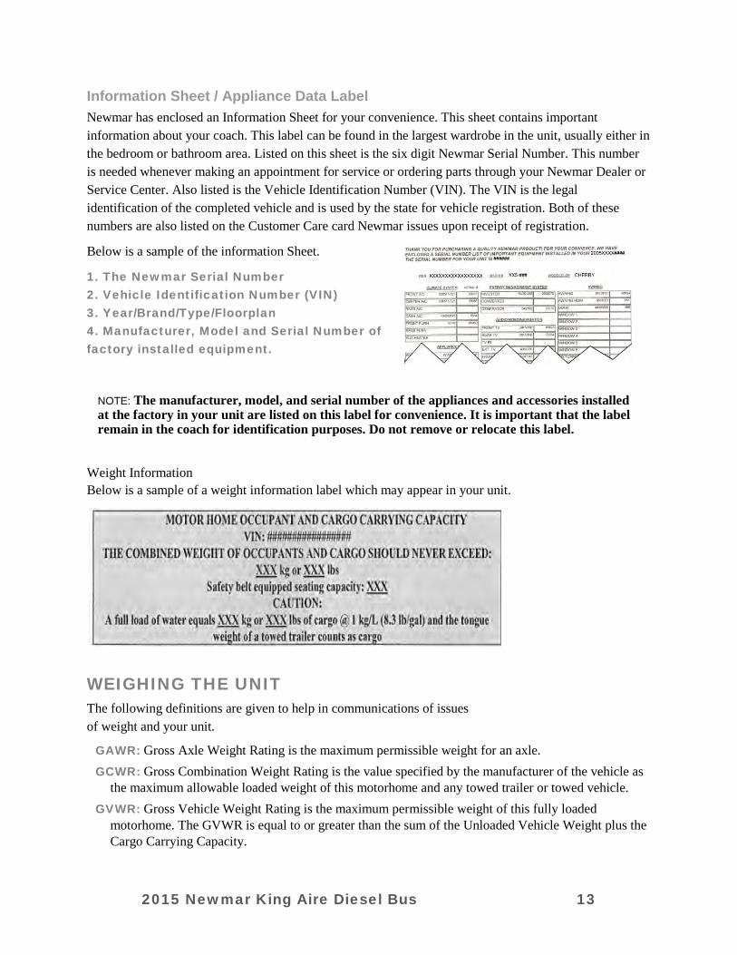
Information Sheet / Appliance Data Label Newmar has enclosed an Information Sheet for your convenience. This sheet contains important information about your coach. This label can be found in the largest wardrobe in the unit, usually either in the bedroom or bathroom area. Listed on this sheet is the six digit Newmar Serial Number. This number is needed whenever making an appointment for service or ordering parts through your Newmar Dealer or Service Center. Also listed is the Vehicle Identification Number (VIN). The VIN is the legal identification of the completed vehicle and is used by the state for vehicle registration. Both of these numbers are also listed on the Customer Care card Newmar issues upon receipt of registration.
Below is a sample of the information Sheet.
1. The Newmar Serial Number 2. Vehicle Identification Number (VIN) 3. Year/Brand/Type/Floorplan 4. Manufacturer, Model and Serial Number of factory installed equipment.
NOTE: The manufacturer, model, and serial number of the appliances and accessories installed at the factory in your unit are listed on this label for convenience. It is important that the label remain in the coach for identification purposes. Do not remove or relocate this label.
Weight Information Below is a sample of a weight information label which may appear in your unit.
WEIGHING THE UNIT The following definitions are given to help in communications of issues of weight and your unit.
GAWR: Gross Axle Weight Rating is the maximum permissible weight for an axle. GCWR: Gross Combination Weight Rating is the value specified by the manufacturer of the vehicle as
the maximum allowable loaded weight of this motorhome and any towed trailer or towed vehicle. GVWR: Gross Vehicle Weight Rating is the maximum permissible weight of this fully loaded
motorhome. The GVWR is equal to or greater than the sum of the Unloaded Vehicle Weight plus the Cargo Carrying Capacity.
2015 Newmar King Aire Diesel Bus 13

UVW: Unloaded Vehicle Weight is the weight of this motorhome as built at the factory with full fuel, engine oil, and coolants. The UVW does not include cargo, fresh water, Propane gas, or dealer installed accessories.
CCC: Cargo Carrying Capacity is equal to GVWR minus each of the following: UVW, full fresh (potable) water weight (including water heater), full Propane-Gas weight and SCWR.
GVW: Gross Vehicle Weight is the weight of the unit with all items and supplies that are loaded into the unit at any point in time.
SCWR: Sleeping Capacity Weight Rating is the manufacturer’s designated number of sleeping positions multiplied by 154 pounds (70 kilograms). NOTE: The sales literature may give approximates or standards. Each individual unit may weigh differently based on the factory and/or dealer options added. To assure the accuracy of your weights be sure the unit is always level during weighing.
The unit has been built to comply with the component suppliers recommended limits and give you a realistic CCC. When loading the unit, distribute the items so that not all of the weight is added to one area of the unit. If you have questions as to what the weight of the unit is after it has been loaded, take the unit to a drive-on scale or use individual wheel scales and verify that the weights are within the limits of those specified for the unit.
When weighing the unit, follow these instructions. Failure to follow these instructions may give an
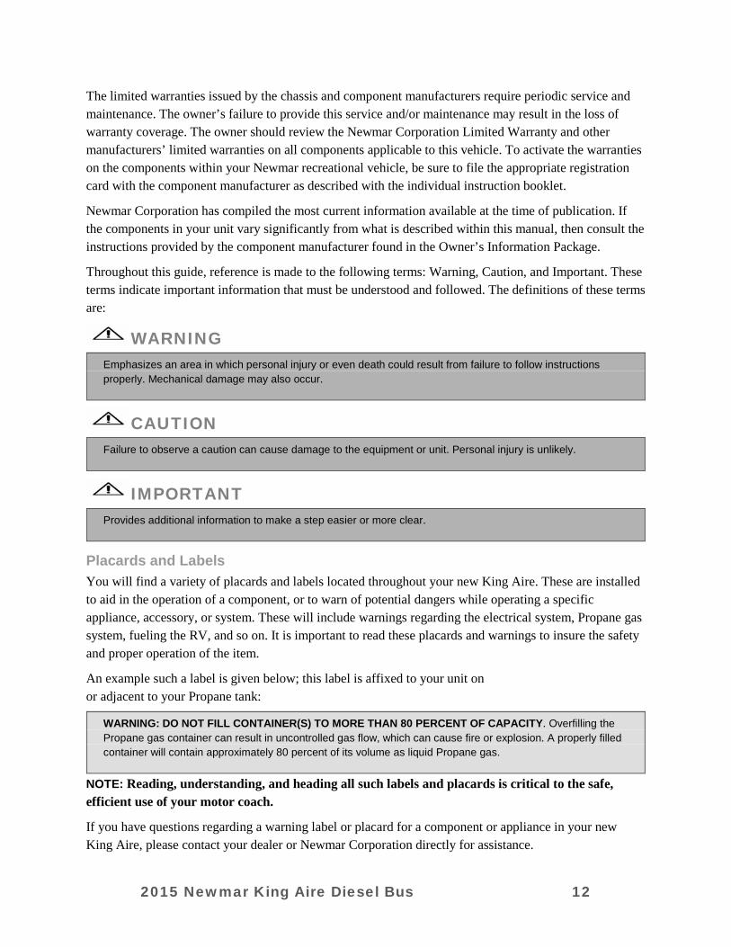
erroneous weight reading. 1. Pull the unit onto the scales shown in Fig. 1. This is the total weight of the unit. To do this, pull the
unit onto the scales so that all of the wheels are on the scale. Record the weight. This is the GVW and should not exceed the GVWR supplied by Newmar for the unit.
2015 Newmar King Aire Diesel Bus 14
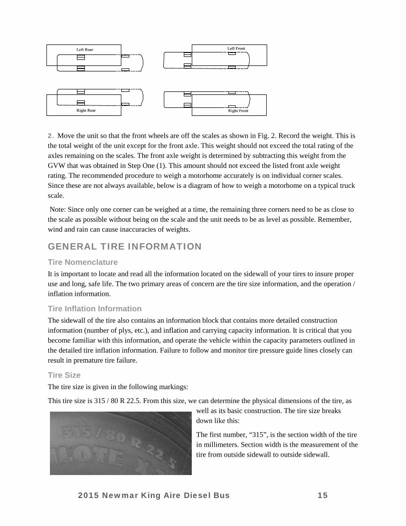
2. Move the unit so that the front wheels are off the scales as shown in Fig. 2. Record the weight. This is the total weight of the unit except for the front axle. This weight should not exceed the total rating of the axles remaining on the scales. The front axle weight is determined by subtracting this weight from the GVW that was obtained in Step One (1). This amount should not exceed the listed front axle weight rating. The recommended procedure to weigh a motorhome accurately is on individual corner scales. Since these are not always available, below is a diagram of how to weigh a motorhome on a typical truck scale.
Note: Since only one corner can be weighed at a time, the remaining three corners need to be as close to the scale as possible without being on the scale and the unit needs to be as level as possible. Remember, wind and rain can cause inaccuracies of weights.
GENERAL TIRE INFORMATION
Tire Nomenclature It is important to locate and read all the information located on the sidewall of your tires to insure proper use and long, safe life. The two primary areas of concern are the tire size information, and the operation / inflation information.
Tire Inflation Information The sidewall of the tire also contains an information block that contains more detailed construction information (number of plys, etc.), and inflation and carrying capacity information. It is critical that you become familiar with this information, and operate the vehicle within the capacity parameters outlined in the detailed tire inflation information. Failure to follow and monitor tire pressure guide lines closely can result in premature tire failure.
Tire Size The tire size is given in the following markings:
This tire size is 315 / 80 R 22.5. From this size, we can determine the physical dimensions of the tire, as well as its basic construction. The tire size breaks down like this:
The first number, “315”, is the section width of the tire in millimeters. Section width is the measurement of the tire from outside sidewall to outside sidewall.
2015 Newmar King Aire Diesel Bus 15

The second number is the height of the sidewall, expressed as a percentage of the section width. In this case, the number is “80”, so the sidewall height is 80% of the section width of the tire.
The “R” in the tire size indicates that this tire is “radial” in construction. The belts are wrapped around the tire in a radial design, from bead to bead.
The final number in the size designation is “22.5”, which is the rim size the tire was designed to fit. This tire fits a 22.5” diameter wheel.
The sidewall of the tire also contains other information that is important to know to insure proper use of the tire, as well as to maintain long life. Take the time to become familiar with the size, load rating, and pressure information noted on the sidewalls of the tires, and note that these readings can change depending on whether they are used in single tire or “dual” tire situations.
IMPORTANT RV TIRE INFORMATION
READ AND UNDERSTAND THE FOLLOWING INFORMATION BEFORE TAKING YOUR FIRST TRIP IN YOUR RV!
WARNING
To insure your tires are operating safely, regular inspection of your tires, and checking of tire pressures is absolutely mandatory. FAILURE TO FOLLOW PROPER INFLATION GUIDELINES MAY RESULT IN TIRE FAILURE, WHICH, UNDER CERTAIN CIRCUMSTANCE CAN CAUSE LOSS OF VEHICLE CONTROL OR ACCIDENTS THAT MAY RESULT IN PROPERTY DAMAGE, BODILY INJURY, AND / OR DEATH. For safe operation and maximum weight carrying capacity, it is imperative that the tires be inflated to and maintained at the listed tire pressures on the Federal ID Tag that is affixed to the interior wall just behind the driver’s seat in motorhomes, and to the lower front corner of the road side sidewall on fifth wheel trailers. Below is a sample of the Federal ID Tag you will find with your RV. IT IS PARAMOUNT TO THE SAFE OPERATION OF THE VEHICLE TO MAINTAIN PROPER TIRE PRESSURES. TIRE PRESSURES SHOULD BE CHECKED AND ADJUSTED BEFORE AND AFTER EACH TRIP, AND SHOULD ALWAYS BE CHECKED AND ADJUSTED WITH THE TIRES COLD. NEVER ADD OR RELEASE PRESSURE FROM THE TIRES WHEN THEY ARE HOT (AFTER HAVING DRIVEN A MILE OR MORE). For additional information on your tires, contact Newmar Corporation.
2015 Newmar King Aire Diesel Bus 16
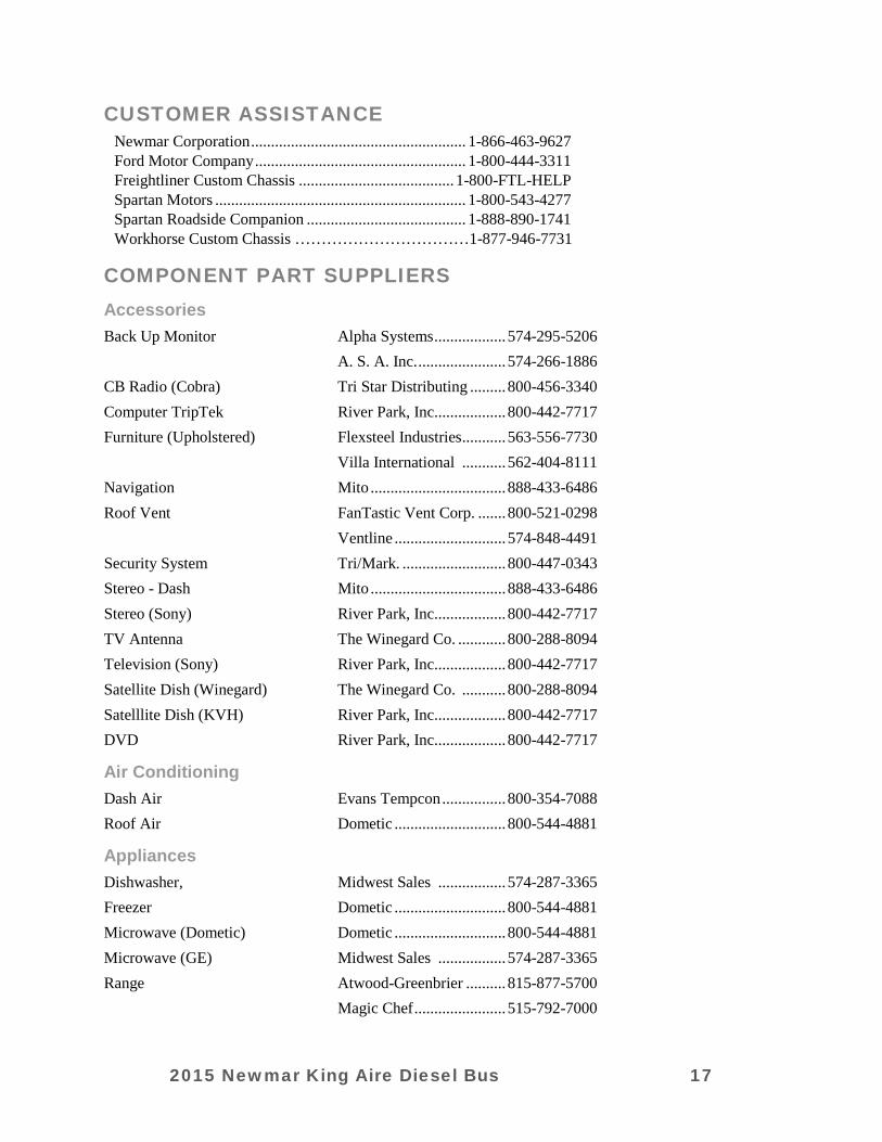
CUSTOMER ASSISTANCE Newmar Corporation ...................................................... 1-866-463-9627 Ford Motor Company ..................................................... 1-800-444-3311 Freightliner Custom Chassis ....................................... 1-800-FTL-HELP Spartan Motors ............................................................... 1-800-543-4277 Spartan Roadside Companion ........................................ 1-888-890-1741 Workhorse Custom Chassis ……………………………1-877-946-7731
COMPONENT PART SUPPLIERS
Accessories Back Up Monitor Alpha Systems .................. 574-295-5206 A. S. A. Inc. ...................... 574-266-1886 CB Radio (Cobra) Tri Star Distributing ......... 800-456-3340 Computer TripTek River Park, Inc.................. 800-442-7717 Furniture (Upholstered) Flexsteel Industries ........... 563-556-7730 Villa International ........... 562-404-8111 Navigation Mito .................................. 888-433-6486 Roof Vent FanTastic Vent Corp. ....... 800-521-0298 Ventline ............................ 574-848-4491 Security System Tri/Mark. .......................... 800-447-0343 Stereo - Dash Mito .................................. 888-433-6486 Stereo (Sony) River Park, Inc.................. 800-442-7717 TV Antenna The Winegard Co. ............ 800-288-8094 Television (Sony) River Park, Inc.................. 800-442-7717 Satellite Dish (Winegard) The Winegard Co. ........... 800-288-8094 Satelllite Dish (KVH) River Park, Inc.................. 800-442-7717 DVD River Park, Inc.................. 800-442-7717
Air Conditioning Dash Air Evans Tempcon ................ 800-354-7088 Roof Air Dometic ............................ 800-544-4881
Appliances Dishwasher, Midwest Sales ................. 574-287-3365 Freezer Dometic ............................ 800-544-4881 Microwave (Dometic) Dometic ............................ 800-544-4881 Microwave (GE) Midwest Sales ................. 574-287-3365 Range Atwood-Greenbrier .......... 815-877-5700 Magic Chef ....................... 515-792-7000
2015 Newmar King Aire Diesel Bus 17

Refrigerator Dometic ............................ 800-544-4881 Norcold ............................. 800-543-1219 Water Heater - Atwood Atwood Mobile Prod. ....... 815-877-5700 Water Heater - Suburban Suburban Mfg. .................. 800-659-2138 Water Heater - Oasis ITR ................................... 800-993-4402 Washer/Dryer, 1-piece Splendide .......................... 800-736-4127 Washer/Dryer, 2-piece Whirlpool ......................... 800-442-1111
Electrical (tires and batteries separately warranted) Batteries - 12Volt Interstate ........................... 800-872-4100 Batteries - 6 Volt Interstate ........................... 888-772-3600 Inverter/Converter Magnum ........................... 425-353-8833 Generators Onan ................................. 800-888-6626
Exterior Awning & Hardware A & E ............................... 800-544-4881 Carefree of Colorado ........ 800-621-2617 Girard ............................... 800-382-8442 Jacks (CA & DP) H W H Corporation .......... 800-321-3494 Jacks (FW) Atwood Mobile Prod. ....... 815-877-5700 Equalizer Systems. ........... 800-846-9659 Rubber Suspension (FW) Mor-Ryde, Inc. ................. 574-293-1581 Steps, Electrical Lippert/Coach Step ........... 574-535-2085 Steps, Electrical Kwikee Products .............. 800-736-9961 Steps, Manual Hickory Springs Mfg. ....... 574-262-2399 Tires Goodyear .......................... 800-227-1999 Michelin ........................... 803-234-5000
Heating Furnaces Atwood Mobile Prod. ....... 815-877-5700 Suburban Mfg. .................. 800-659-2138 Furnace, Hydronic ITR ................................... 800-993-4402
2015 Newmar King Aire Diesel Bus 18
CHAPTER 2
GENERAL & SAFETY INFORMATION
DRIVING AND SAFETY INFORMATION
WARNING
Prior to driving your vehicle, be sure you have read this entire owner’s guide and that you understand your vehicle’s equipment completely and how to use the equipment safely. Read and understand all of the instructions and precautions in this owner’s guide and the chassis manufacturer owner’s manual before operating your new motorhome. Listed below are some safety precautions that must be adhered to while your motorhome is in motion. These precautions, as well as others that involve possible damage to equipment, are also listed in the appropriate areas in this manual.
Before Driving Away The following is a brief list of procedures that will aid in your driving safety and extend your equipment’s life.
• Windows, mirrors, and light lenses are to be clean and unobstructed. • Tires should be checked for proper cold inflation pressure. • Wheel lug nuts should be checked for proper tightness. • Fluid levels, including engine oil, transmission fluid, coolant, power steering fluid, and windshield
washer solvent, should be checked and filled if necessary. • Disconnect the unit and store the sewer and water supply hoses as well as shoreline power cords. • Secure all cargo in the storage compartments in the event of a sudden stop. • Verify that the entrance step has retracted prior to engine ignition.
Driving There are various adjustments that need to be made prior to starting and moving the vehicle.
• Among them are the driver’s seat, the tilt steering, and the exterior rear view mirrors. • The dashboard may contain several gauges and controls you have not previously used. Become
familiar with all of these devices and their operation before starting out. • The cruise control is not to be operated on icy roads, extremely wet roads, winding roads, heavy
traffic, or in any other traffic situation where a constant speed cannot be maintained. • While driving on slippery surfaces, use care when accelerating or decelerating. Skidding and loss of
vehicle control may be the result of abrupt changes in speed. • Driving through water deep enough to wet the brakes may affect the stopping distance or cause the
vehicle to pull to one side. • If you have driven through deep water, check the brake operation in a safe area to be sure they have
not been affected. Never operate a vehicle if a difference in braking efficiency is noticeable. • Extreme terrain and adverse weather may affect the handling and/or performance of your vehicle.
Please refer to your chassis manual for related information.
2015 Newmar King Aire Diesel Bus 19
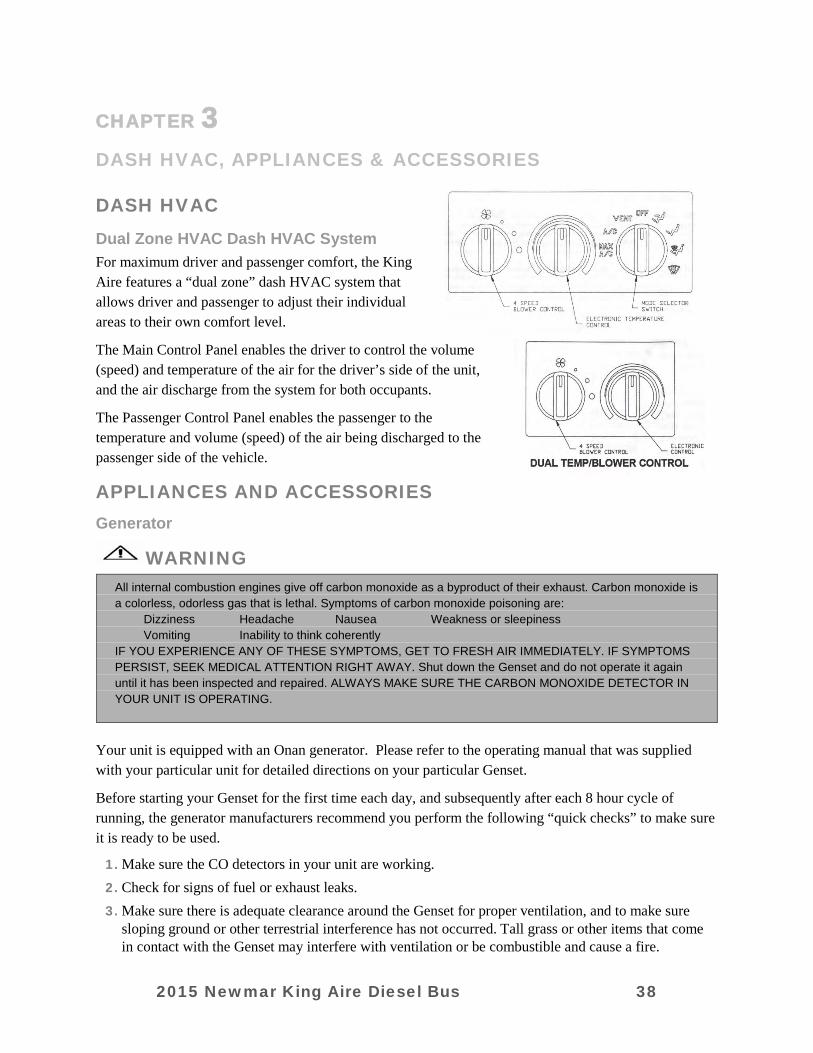
Dash Instrumentation and Controls The dash in your new King Aire is designed to be ergonomically efficient as well as aesthetically pleasing. It features instrumentation that allows you to monitor the engine, chassis, and power train as you drive.
Warning and status lights alert you to conditions that require your attention, and switches, buttons, and accessories are positioned at your fingertips. All dash gauges are “back-lit” for enhanced visibility during night driving. The gauges are arranged as follows:
Left Cluster Voltage: Displays DC voltage at the chassis battery terminals. Note that some variation in the readings on this gauge is normal. With the ignition key in the “run” position, but the engine shut off, it will read chassis battery voltage. If the engine is running, the voltage displayed reflects the DC voltage being supplied by the engine alternator as measured at the chassis batteries.
Fuel: Displays the approximate level of fuel left as a fraction of a tank (“Full”, “3/4”, “1/2”, “1/4”, and “Empty”). Note that accuracy of this gauge is greatly influenced by motion of the unit, or sloped terrain. The readings are an approximation of the remaining fuel in the tank.
Front Air Tank: Displays the air pressure in the front air tank. The normal operating range for this air system is 90 – 125 PSI. Air from the engine mounted compressor fills the tank when the engine is running. The air is used to inflate air suspension bags, and to operate the air brakes on your King Aire, as well as any other air powered accessories.
Rear Air Tank: Displays the air pressure in the rear air tank. The normal operating range for this air system is 90 – 125 PSI. Air from the engine mounted compressor fills the tank when the engine is running. The air is used to inflate air suspension bags, and to operate the air brakes on your King Aire, as well as any other air powered accessories.
Center Cluster Speedometer: Reads vehicle speed in miles per hour / kilometers per hour.
Odometer: Cumulative miles on your King Aire are displayed on the screen located at the bottom of the speedometer. This electronic digital display allows for easy reading. The odometer also incorporates two separate “trip” odometers, which can be reset to “0” using the button at the bottom of the display. This feature is useful for reference mileages when measuring fuel economy or trip distances.
Right Cluster Tachometer: Displays engine RPM’s (Revolutions per Minute) when running.
Oil Pressure: Displays engine oil pressure in PSI (Pounds per Square Inch). Oil pressure will vary widely with engine temperature and engine operating RPM’s.
Temperature: Displays engine operating temperature. Normal operating temperatures are 180 – 220 degrees, depending on how the coach is being used. Towing heavy loads, or operating in the mountains will cause the engine temperature to run higher.
2015 Newmar King Aire Diesel Bus 20
Jacks Down Warning Your unit features a “Jacks Down” warning as part of the “Message Center” under the instrument cluster. The display and alarm will continue until all of the jacks have returned to their “stored” position or unit air system has been replenished.
Antennae Up Warning This warning also appears in the “Message Center” when the television antennae (NOT the DSS satellite dish) are in the extended position. It will turn off when the TV antenna is retracted completely into the “travel” position. There is no accompanying alarm with this warning.
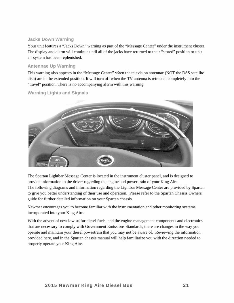
Warning Lights and Signals
The Spartan Lightbar Message Center is located in the instrument cluster panel, and is designed to provide information to the driver regarding the engine and power train of your King Aire. The following diagrams and information regarding the Lightbar Message Center are provided by Spartan to give you better understanding of their use and operation. Please refer to the Spartan Chassis Owners guide for further detailed information on your Spartan chassis.
Newmar encourages you to become familiar with the instrumentation and other monitoring systems incorporated into your King Aire.
With the advent of new low sulfur diesel fuels, and the engine management components and electronics that are necessary to comply with Government Emissions Standards, there are changes in the way you operate and maintain your diesel powertrain that you may not be aware of. Reviewing the information provided here, and in the Spartan chassis manual will help familiarize you with the direction needed to properly operate your King Aire.
2015 Newmar King Aire Diesel Bus 21
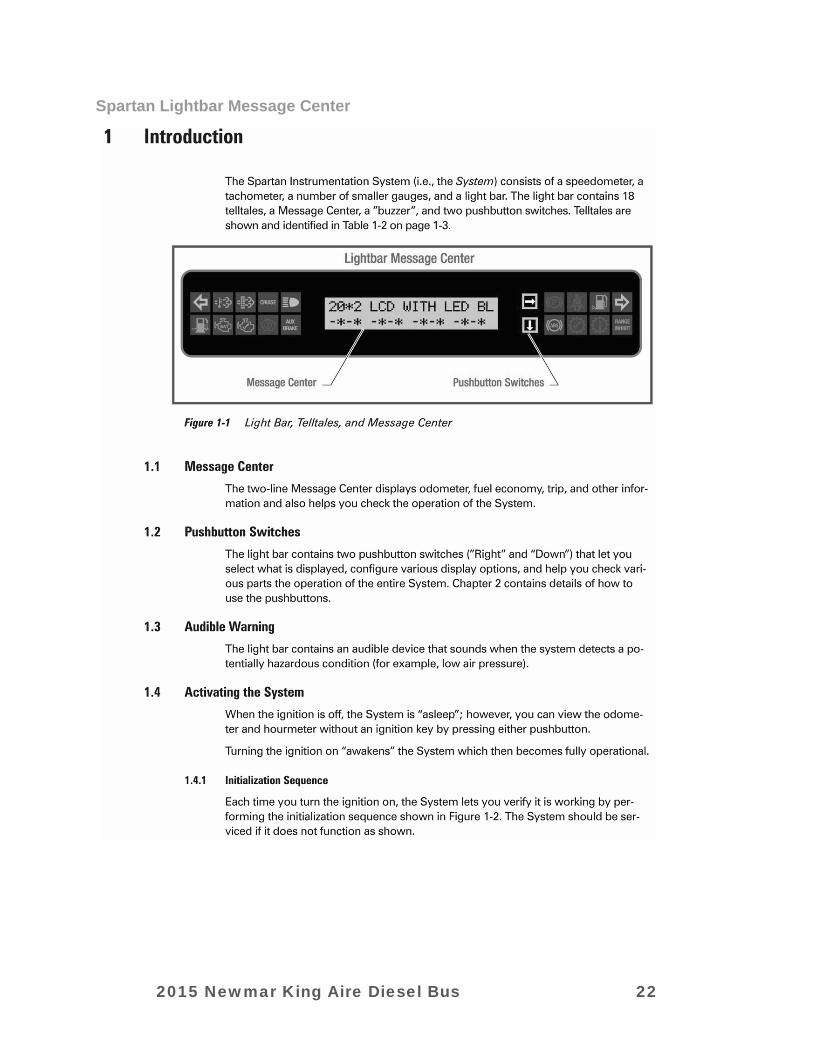
Spartan Lightbar Message Center
2015 Newmar King Aire Diesel Bus 22
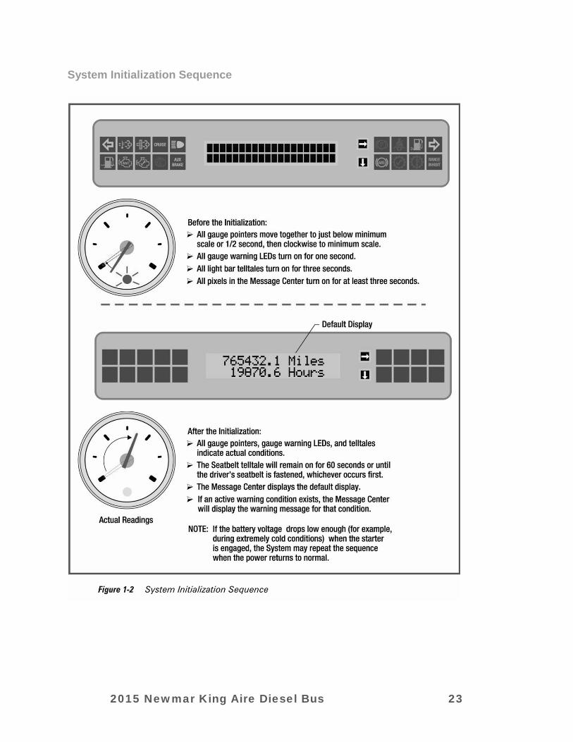
System Initialization Sequence
2015 Newmar King Aire Diesel Bus 23

“Telltale” Warning Light Information
2015 Newmar King Aire Diesel Bus 24

Spartan Smart Wheel (w/ Power Pedal controls)
The Spartan “Smart Wheel” offers a touch pad switch panel that allows you to operate a number of different driver related functions without ever having to take your hands off of the steering wheel. It offers fingertip control of wipers, washers, headlamps.
On the sides of the steering wheel switch pad are three rocker switches. These switches control the tilt and telescope position of the steering column, and the position of the brake and throttle pedals. The first switch (on the left) tilts the steering column up and down to allow for easy access to the driver’s seat, while still allowing the driver to position the wheel for comfort and an excellent view of the instruments. The right side top switch allows the driver to telescope the steering wheel position in or out, again to provide for greater comfort and an unimpaired view of the gauges.
The right side bottom switch moves the brake and throttle pedals under the dash. This allows for greater flexibility in seating position, as well as improved individual access to the pedals.
Seat Memory Your King Aire is equipped with a “Seat Memory” package that allows you to set and store up three different combinations of seat, steering wheel, pedal, and exterior rear view mirror positions for up to three different drivers.
To program a driving position, position the seat, the pedals, steering wheel and exterior rear view mirrors so they are set for travel. Press and hold “Set”, then press and release either the #1, #2, or #3 button. The position of each of those components is now stored in the memory. Any time you turn the ignition on and press the number button chosen, the seat, pedals, steering wheel, and exterior rear view mirrors will return to this preset position.
Dash Switches To ease operation of the various accessories and systems used during travel, the “cockpit” area has been designed to put controls and switches within easy reach of the driver. The following is a description of the switches and their functions.
(Switches)
1 2 3 4 5 6 7 8 9 10 11 12
2015 Newmar King Aire Diesel Bus 25
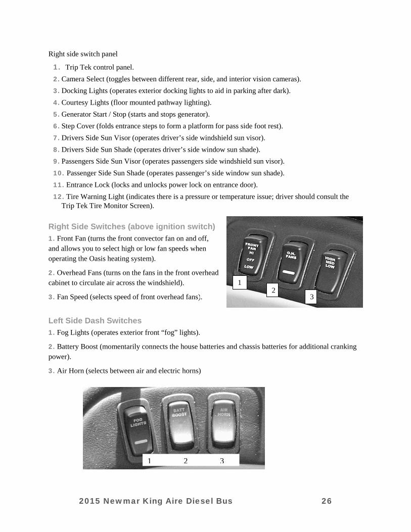
Right side switch panel
1. Trip Tek control panel. 2. Camera Select (toggles between different rear, side, and interior vision cameras). 3. Docking Lights (operates exterior docking lights to aid in parking after dark). 4. Courtesy Lights (floor mounted pathway lighting). 5. Generator Start / Stop (starts and stops generator). 6. Step Cover (folds entrance steps to form a platform for pass side foot rest). 7. Drivers Side Sun Visor (operates driver’s side windshield sun visor). 8. Drivers Side Sun Shade (operates driver’s side window sun shade). 9. Passengers Side Sun Visor (operates passengers side windshield sun visor). 10. Passenger Side Sun Shade (operates passenger’s side window sun shade). 11. Entrance Lock (locks and unlocks power lock on entrance door). 12. Tire Warning Light (indicates there is a pressure or temperature issue; driver should consult the
Trip Tek Tire Monitor Screen). Right Side Switches (above ignition switch) 1. Front Fan (turns the front convector fan on and off, and allows you to select high or low fan speeds when operating the Oasis heating system).
2. Overhead Fans (turns on the fans in the front overhead cabinet to circulate air across the windshield).
3. Fan Speed (selects speed of front overhead fans).
Left Side Dash Switches 1. Fog Lights (operates exterior front “fog” lights).
2. Battery Boost (momentarily connects the house batteries and chassis batteries for additional cranking power).
3. Air Horn (selects between air and electric horns)
1 2 3
1 2
3
2015 Newmar King Aire Diesel Bus 26

Drivers Side Console Switches
1. ATC Switch turns the Automatic Traction Control system on and off.
2. Power Mirror Control Pad (adjusts exterior rear view mirror position. Also operates mirror heat for improved visibility in adverse conditions).
3. Memory Seat Control Pad (allows programming of up to three different driving positions into a memory).
4. Engine Brake Switch (operates engine brake; “Hi” and “Low” selectable).
5. Tag Axle Dump (bleeds the air out of the tag axle suspension to place more weight on the drive axle tires for improved traction in slippery conditions).
6. Drivers Power Window Switch (operates driver’s side power window).
7. Transmission Selector Pad (operates Allison transmission).
8. Hadley Air Leveling system control pad.
9. HWH Leveling Jack Control Panel (located at the end of the driver’s side armrest).
Passenger Side Console Switches 1. Patio Light (operates exterior patio light).
2. Power Visor (operates passenger side front sun visor).
3. Power Shade (operates passenger side power sun shade).
4. Map Light (operates passenger side map light).
5. Interior Lights (operates the four front overhead interior lights to illuminate the steps as you enter).
6. Power Door Locks (power locking for the entrance and basement doors).
7. Passenger Side HVAC Control Panel (allows passenger to tailor the dash HVAC to their comfort).
2015 Newmar King Aire Diesel Bus 27
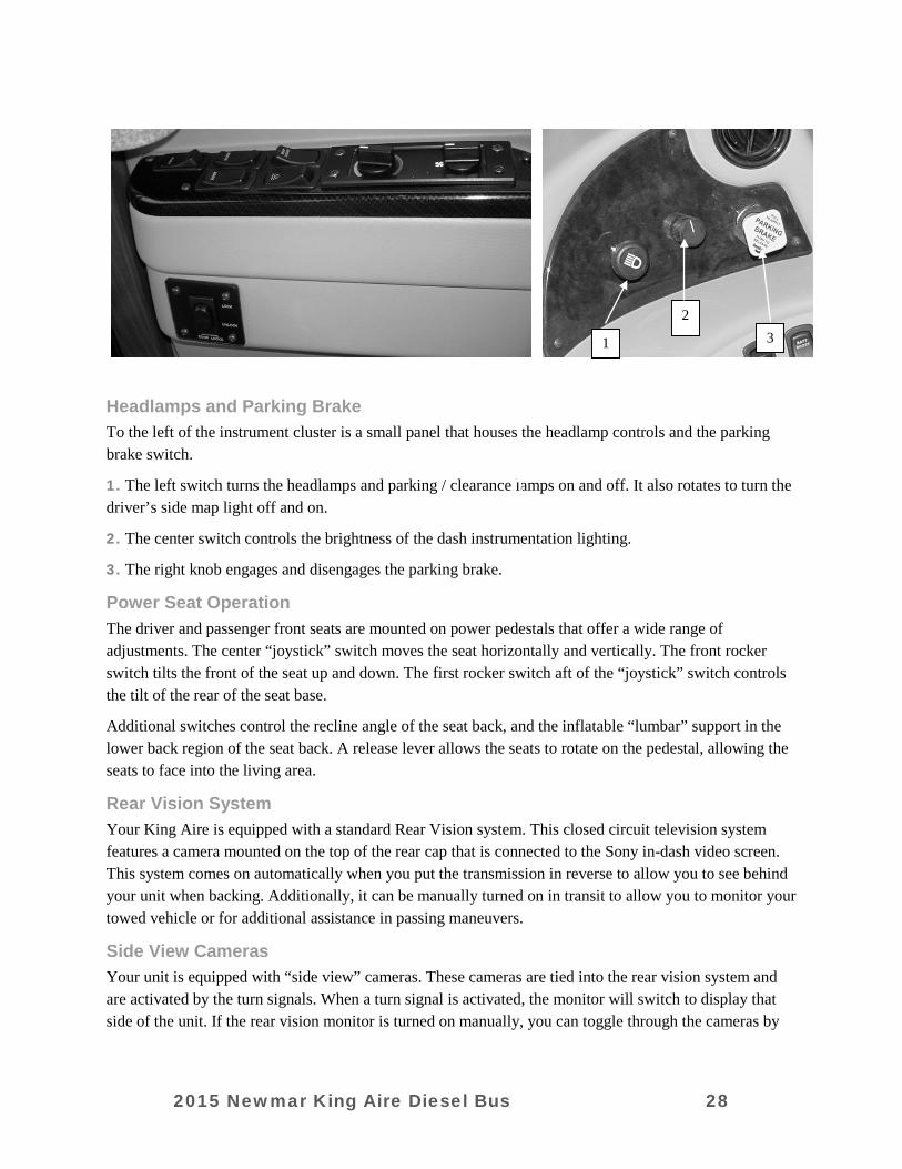
Headlamps and Parking Brake To the left of the instrument cluster is a small panel that houses the headlamp controls and the parking brake switch.
1. The left switch turns the headlamps and parking / clearance lamps on and off. It also rotates to turn the driver’s side map light off and on.
2. The center switch controls the brightness of the dash instrumentation lighting.
3. The right knob engages and disengages the parking brake.
Power Seat Operation The driver and passenger front seats are mounted on power pedestals that offer a wide range of adjustments. The center “joystick” switch moves the seat horizontally and vertically. The front rocker switch tilts the front of the seat up and down. The first rocker switch aft of the “joystick” switch controls the tilt of the rear of the seat base.
Additional switches control the recline angle of the seat back, and the inflatable “lumbar” support in the lower back region of the seat back. A release lever allows the seats to rotate on the pedestal, allowing the seats to face into the living area.
Rear Vision System Your King Aire is equipped with a standard Rear Vision system. This closed circuit television system features a camera mounted on the top of the rear cap that is connected to the Sony in-dash video screen. This system comes on automatically when you put the transmission in reverse to allow you to see behind your unit when backing. Additionally, it can be manually turned on in transit to allow you to monitor your towed vehicle or for additional assistance in passing maneuvers.
Side View Cameras Your unit is equipped with “side view” cameras. These cameras are tied into the rear vision system and are activated by the turn signals. When a turn signal is activated, the monitor will switch to display that side of the unit. If the rear vision monitor is turned on manually, you can toggle through the cameras by
1
2 3
2015 Newmar King Aire Diesel Bus 28
using the “Camera Select” source button (see page 2:11 for dash location), allowing you to stay on any given camera that you chose.
Trip Tek Monitoring System Your King Aire is equipped with the “Trip Tek” Monitoring system. This system uses the rear vision monitor panel to display information regarding engine and powertrain use and maintenance, generator use and maintenance, trip, and tire temp and pressure information.
By using the Trip Tek control panel (located above the in-dash radio), you can scroll through the various menus on the rear vision monitor screen to select the information you seek, and to program and reset service interval reminders.
For detailed operating instructions, please refer to the Trip Tek operators guide supplied with your new King Aire.
Sony In-Dash Stereo Your King Aire features a Sony AM/FM/CD in-dash stereo. This stereo plays through separate speakers from the other audio – video equipment in your coach. This radio features up to 18 radio presets, a variety of tone controls, and a CD player. It is also XM satellite radio capable, and also controls the standard 6 CD changer.
To operate the stereo, press the “Source” button in the upper left hand corner of the radio face. Pressing the source button once turns the stereo on playing the last mode selected (AM, FM, CD, etc.). Use the “Source” button to alternate between music sources.
For detailed operating instructions on your Sony stereo, please refer to the manufacturer’s information provided with your unit. XM satellite radio is available by contacting the XM provider directly. A monthly fee is involved to subscribe.
CD Changer A six disc CD changer is standard in the King Aire. It is designed to work with your factory mounted Sony in dash stereo. Use the “Source” button on the face of the Sony stereo to select the CD changer, and then use the controls and display on the face of the stereo to select the disc and song you want to hear.
Navigation System Your King Aire is equipped with a GPS based Navigation system. This system uses GPS technology to guide you through maps and information for traveling assistance. It features voice prompts, and a remote control to make scrolling through the menus and getting information easy.
To begin operation, simply turn on the system and follow the simple commands that appear on the screen. Detailed manufacturer’s instructions are included with your King Aire literature.
Buddy Screen Pass. Side Nav. Monitor (optional) As an option for the Pioneer Navigation system, a second monitor for the navigation system is available for the passenger side. This monitor is located under the front overhead cabinet, just inside the entrance door. It is mounted on a swiveling, tilting head so positioning it for maximum comfort is possible.
2015 Newmar King Aire Diesel Bus 29
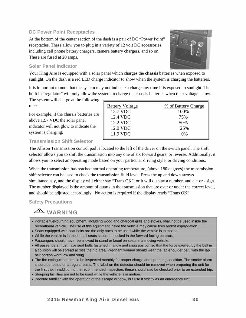
DC Power Point Receptacles At the bottom of the center section of the dash is a pair of DC “Power Point” receptacles. These allow you to plug in a variety of 12 volt DC accessories, including cell phone battery chargers, camera battery chargers, and so on. These are fused at 20 amps.
Solar Panel Indicator Your King Aire is equipped with a solar panel which charges the chassis batteries when exposed to sunlight. On the dash is a red LED charge indicator to show when the system is charging the batteries.
It is important to note that the system may not indicate a charge any time it is exposed to sunlight. The built in “regulator” will only allow the system to charge the chassis batteries when their voltage is low. The system will charge at the following rate:
For example, if the chassis batteries are above 12.7 VDC the solar panel indicator will not glow to indicate the system is charging.
Transmission Shift Selector The Allison Transmission control pad is located to the left of the driver on the switch panel. The shift selector allows you to shift the transmission into any one of six forward gears, or reverse. Additionally, it allows you to select an operating mode based on your particular driving style, or driving conditions.
When the transmission has reached normal operating temperature, (above 180 degrees) the transmission shift selector can be used to check the transmission fluid level. Press the up and down arrows simultaneously, and the display will either say “Trans OK”, or it will display a number, and a + or - sign. The number displayed is the amount of quarts in the transmission that are over or under the correct level, and should be adjusted accordingly. No action is required if the display reads “Trans OK”.
Safety Precautions
WARNING
• Portable fuel-burning equipment, including wood and charcoal grills and stoves, shall not be used inside the recreational vehicle. The use of this equipment inside the vehicle may cause fires and/or asphyxiation.
• Seats equipped with seat belts are the only ones to be used while the vehicle is in motion. • While the vehicle is in motion, all seats should be locked in the forward facing position. • Passengers should never be allowed to stand or kneel on seats in a moving vehicle. • All passengers must have seat belts fastened in a low and snug position so that the force exerted by the belt in
a collision will be spread across the hip area. Pregnant women should wear the lap-shoulder belt, with the lap belt portion worn low and snug.
• The fire extinguisher should be inspected monthly for proper charge and operating condition. The smoke alarm should be tested on a regular basis. The label on the detector should be removed when preparing the unit for the first trip. In addition to the recommended inspection, these should also be checked prior to an extended trip.
• Sleeping facilities are not to be used while the vehicle is in motion. • Become familiar with the operation of the escape window, but use it strictly as an emergency exit.
Battery Voltage % of Battery Charge 12.7 VDC 100% 12.4 VDC 75% 12.2 VDC 50% 12.0 VDC 25% 11.9 VDC 0%
2015 Newmar King Aire Diesel Bus 30

Occupant Restraints One of the most important safety features in your vehicle is the restraint system. Research has shown that seat belts save lives. And they can reduce the seriousness of injuries in a collision. Some of the worst injuries happen when people are thrown from the vehicle. EVERYONE IN A MOTOR VEHICLE NEEDS TO BE BUCKLED UP AT ALL TIMES.
WARNING
It is extremely dangerous to ride in a cargo area, inside or outside of a vehicle. In a collision, people riding in these areas are more likely to be seriously injured or killed. Do not allow people to ride in any area of your vehicle that is not equipped with seat belts. BE SURE EVERYONE IN YOUR VEHICLE IS USING A PROPER SEAT BELT.
Please pay close attention to the information in this section. It tells you how to use your restraint system properly. If you wear your safety belt improperly, both the effectiveness and comfort will decrease.
• Do not allow the buckle to be located in the stomach or abdomen area.
• Do not wear the shoulder strap under your arm or behind your back.
• Do not wear the shoulder belt too snug, or let it rub against your neck.
• Do not allow the belts to become too loose as you travel.
If the lap and/or shoulder belts are too loose, they may not be able to hold you in place during a crash.
• Do wear the lap belt low on the hips, two to four inches below the waist, and against the thighs. The strong bones of the hips can absorb the forces experienced in a crash.
• Do wear the shoulder strap across the center of the chest and the center of the shoulder. Lap/Shoulder Belt Operating Instructions
1. Enter the vehicle and close the door. Sit back and adjust the seat.
2. The latch plate of the belt is above the back of your seat. Grasp the latch plate and pull out the belt. Slide the latch plate up the webbing as far as necessary to make the belt go around your lap.
3. When the belt is long enough to fit, insert latch plate into buckle until you hear a “click.”
4. Position the lap belt across your thigh, below your abdomen. If you need the lap portion tighter, pull up a bit on the shoulder part. A snug belt reduces the risk of sliding under the belt in a collision. Position the shoulder belt on your chest so that it is comfortable and not resting on your neck. The retractor will withdraw any slack in the belt.
5. To release the belt, push the release button on the buckle. Adjustable Upper Shoulder Belt Anchorage Some shoulder belts can be adjusted upward or downward to help position the belt away from your neck. Push on the anchorage cover to release the anchorage, and then move it up or down to the position that serves you best.
2015 Newmar King Aire Diesel Bus 31
Child Restraint Everyone in your vehicle needs to be buckled up all the time. Every state in the United States and all Canadian provinces require that small children ride in proper restraint systems. This is the law, and you can be prosecuted for ignoring it. There are different sizes and types of restraints for children from newborn size to the child almost large enough for the adult seat belt. Use the restraint that is correct for your child:
• The restraint must be appropriate for your child's weight and height. Check the label on the restraint for this, too.
• Carefully follow the instructions that come with the restraint. If you install the restraint improperly it may not work when you need it
• Buckle the child into the restraint exactly as the manufacturer's instructions tell you.
MAINTAIN YOUR RESTRAINT SYSTEM Periodically examine your restraint equipment to be sure it functions correctly and to be sure there are no worn or broken components that either needs repair or replacement. Damaged parts must be replaced immediately. Do not disassemble or modify the system. Restraint equipment must be replaced after an accident if they have been damaged. If there is any question regarding belt or retractor condition, replace the belt.
It is a good idea to have your restraint system inspected during each periodic scheduled maintenance session.
WARNING A frayed or torn belt could rip apart in a collision and leave you with no protection. Inspect the belt system periodically, checking for cuts, frays, or loose parts. Damaged parts must be replaced immediately. Do not disassemble or modify the system. Seat belt assemblies must be replaced after an accident if they have been damaged (bent retractor, torn webbing, etc.)
Safety Belt Maintenance If the belts need cleaning, use a mild soap solution or lukewarm water. Do not remove the belts from the vehicle to wash them.
WARNING
Do not bleach, dye or clean the belts with chemical solvents or abrasive cleaners. This may severely weaken the fabric. In a crash, they might not be able to provide adequate protection.
PROPANE GAS & FUEL
WARNING
Propane cylinders shall not be placed or stored inside the vehicle. Propane cylinders are equipped with safety devices that relieve excessive pressure by discharging propane to the atmosphere. FAILURE TO COMPLY COULD RESULT IN DEATH OR SERIOUS INJURY.
2015 Newmar King Aire Diesel Bus 32

WARNING
IT IS NOT SAFE TO USE COOKING APPLIANCES FOR COMFORT HEATING. Cooking appliances need fresh air for safe operation. Before operation: (1) Open overhead vent or turn on exhaust fan (2) Open window FAILURE TO COMPLY COULD RESULT IN DEATH OR SERIOUS INJURY. Unlike homes, the amount of oxygen supply is limited due to the size of the recreation vehicle, and proper ventilation when using the cooking appliance(s) avoids dangers of asphyxiation. It is especially important that cooking appliances not be used for comfort heating, as the danger of asphyxiation is greater when the appliance is used for long periods of time.
WARNING
DO NOT FILL PROPANE CONTAINER(S) TO MORE THAN 80 PERCENT OF CAPACITY. Overfilling the propane container can result in uncontrolled propane flow, which can cause fire or explosion. A properly filled container contains approximately 80 percent of its volume as liquid propane. FAILURE TO COMPLY COULD RESULT IN DEATH OR SERIOUS INJURY.
WARNING
Portable fuel-burning equipment, including wood and charcoal grills and stoves, shall not be used inside the recreational vehicle. The use of this equipment inside the recreational vehicle can cause fire or asphyxiation. FAILURE TO COMPLY COULD RESULT IN DEATH OR SERIOUS INJURY.
WARNING
DO NOT BRING OR STORE PROPANE CYLINDERS, GASOLINE, OR OTHER FLAMMABLE LIQUIDS INSIDE THE VEHICLE. FAILURE TO COMPLY COULD RESULT IN FIRE OR EXPLOSION
DANGER
IF YOU SMELL PROPANE: (1) Extinguish any open flames, pilot lights, and all smoking materials (2) Do not touch electrical switches (3) Shut off the propane supply at the container valve(s) or propane supply connection (4) Open doors and other ventilating openings (5) Leave the area until odor clears (6) Have the propane system checked and leakage source corrected before using again FAILURE TO COMPLY COULD RESULT IN EXPLOSION RESULTING IN DEATH OR SERIOUS INJURY.
CAUTION
Propane regulators must always be installed with the regulator vent facing forward. Regulators that are not in compartments have been equipped with a protective cover. Make sure that the regulator vent faces downward and that the cover is kept in place to minimize vent blockage that could result in excessive propane pressure causing fire or explosion.
2015 Newmar King Aire Diesel Bus 33
Propane Gas System General Information A warning label has been placed near the Propane gas container. This label reads:
WARNING: DO NOT FILL CONTAINER(S) TO MORE THAN 80 PERCENT OF CAPACITY. Overfilling the Propane gas container can result in uncontrolled gas flow, which can cause fire or explosion. A properly filled container will contain approximately 80 percent of its volume as liquid Propane gas.
The Propane gas system components in your unit have been approved for use in camping vehicles by a nationally recognized testing laboratory. Propane gas is a clean-burning dependable fuel when properly handled. The Propane gas tank mounted on your unit contains liquid propane gas under high pressure.
The liquid gas vaporizes as the fuel is used and passes through the tank valve to a regulator that automatically reduces the pressure. The low-pressure gas is then distributed to the appliances through the pipe manifold system. Appliance lighting problems are commonly caused by an improperly adjusted gas regulator. Never attempt to reset the regulator yourself. Have an authorized service technician make any necessary adjustments. We recommend that you have the Propane gas system checked by an authorized service technician at least once a year and after every extended trip.
Although the manufacturer and dealer carefully test for leakage, travel vibrations could loosen fittings. Leaks can be easily found by applying leak detector solution at the connections.
If leak detector solution is not available, a soapy water solution made with dish soap can be used. Tightening the fitting usually stops any leaks. If this does not work, shut off the main gas valve at the tank and immediately consult an authorized service technician for repairs. If a leak is suspected, the identifying odor smells similar to rotten eggs (sulfur). Never test for a leak by lighting a match or having an open flame where you suspect leaking gas.
WARNING
Shut off the main gas valve at the tank when the camping vehicle is not in use. Also, shut off the valve when refueling to avoid potential danger from pilot lights igniting fuel fumes. Some appliances, such as the refrigerator, have DSI (direct spark ignition) boards, so it is important that you turn the appliances off when the Propane gas is off. The ignition in the appliances will continue to spark even if there is no Propane gas available.
Propane Regulator The regulator acts as the heart for the Propane gas system. The Propane gas in the tank is under high pressure. The regulator reduces the pressure of this gas so that it is safe to use with the various appliances in your unit. If corrosion is noticed, contact a qualified Propane gas service technician. Do not adjust the regulator. It is factory preset. Adjustments are to be made by a qualified Propane service technician using specialized equipment.
Propane gas regulators must always be installed with the diaphragm vent facing downward. Regulators that are not in compartments have been equipped with a protective cover. Make sure that the regulator vent faces downward and that the cover is kept in place to minimize the vent blockage that could result in excessive gas pressure causing fire or explosion.
2015 Newmar King Aire Diesel Bus 34
Propane Distribution Lines The primary manifold is a black steel pipe running the length of your unit. Most secondary lines leading to gas appliances are made of copper tubing with flare fittings. If any of the gas lines rupture, do not attempt to splice them. Always run a new line. We recommend gas distribution work be performed by an authorized service technician. The main valve at the Propane tank must be closed when removing or servicing any gas appliance. This will prevent dangerous gas leakage that could result in an explosion and possibly serious injury. If a leak is suspected, have the systems inspected and repaired by a qualified service technician.
Precautions & Recommendations • Inspect the Propane fill valve for foreign materials before refueling.
• Shut the pilot lights off prior to refueling Propane gas tanks.
• Never check for gas leaks with an open flame (match, lighter, etc.).
• Gas lines should be visually inspected periodically.
• Have the gas system inspected yearly and before and after extended trips.
• The gas system should be inspected and repaired by qualified technicians only.
WARNING
The Propane system in your recreational vehicle is designed for liquefied petroleum gas only. Never attempt to connect natural gas or butane gas in this system.
Fire Safety The possibility of fire exists in all areas of life, and the recreational life-style is no exception. Recreational vehicles are complex machines. They are made up of many materials, some of which are flammable. Like most hazards, the possibility of fire can be minimized, if not totally eliminated. This is done by recognizing the danger and practicing common sense safety and maintenance habits. For safety reasons, your unit is furnished with both a fire extinguisher and a smoke alarm.
Fire Extinguisher The fire extinguisher is rated for Class B (grease, gasoline, diesel fuel, flammable liquids) and Class C (electrical) fires. These are the most common types of fires in vehicles. Read the operator’s manual and the instructions on the fire extinguisher. Be sure to know how and when to use the extinguisher and where it is located.
Fire extinguishers are mechanical, pressurized devices. Care must be exercised when they are handled. They must be maintained as the operator’s manual instructs for proper and safe operation. The extinguisher should be inspected at least once a month. More frequent inspections may be required if the extinguisher is exposed to the weather or to possible tampering. Do not test the extinguisher by partially discharging. Doing this will cause a loss of pressure.
2015 Newmar King Aire Diesel Bus 35
If a fire occurs in the vehicle, evacuate the vehicle as quickly and as safely as possible. Consider the cause and the severity of the fire and the risk involved before trying to extinguish it. If the fire is major or fuel fed, move away from and stand clear of the vehicle and wait for emergency assistance to arrive.
IMPORTANT
NEVER spray any type of aerosol or cleaner directly onto or into the Propane, CO, and Smoke detectors. Spraying any type of material into the opening on any of these detectors can render them useless, and would not be covered by the manufacturer’s warranty.
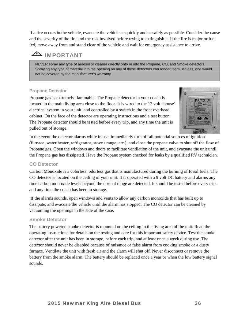
Propane Detector Propane gas is extremely flammable. The Propane detector in your coach is located in the main living area close to the floor. It is wired to the 12 volt “house’ electrical system in your unit, and controlled by a switch in the front overhead cabinet. On the face of the detector are operating instructions and a test button. The Propane detector should be tested before every trip, and any time the unit is pulled out of storage.
In the event the detector alarms while in use, immediately turn off all potential sources of ignition (furnace, water heater, refrigerator, stove / range, etc.), and close the propane valve to shut off the flow of Propane gas. Open the windows and doors to facilitate ventilation of the unit, and evacuate the unit until the Propane gas has dissipated. Have the Propane system checked for leaks by a qualified RV technician.
CO Detector Carbon Monoxide is a colorless, odorless gas that is manufactured during the burning of fossil fuels. The CO detector is located on the ceiling of your unit. It is operated with a 9 volt DC battery and alarms any time carbon monoxide levels beyond the normal range are detected. It should be tested before every trip, and any time the coach has been in storage.
If the alarms sounds, open windows and vents to allow any carbon monoxide that has built up to dissipate, and evacuate the vehicle until the alarm has stopped. The CO detector can be cleaned by vacuuming the openings in the side of the case.
Smoke Detector The battery powered smoke detector is mounted on the ceiling in the living area of the unit. Read the operating instructions for details on the testing and care for this important safety device. Test the smoke detector after the unit has been in storage, before each trip, and at least once a week during use. The detector should never be disabled because of nuisance or false alarm from cooking smoke or a dusty furnace. Ventilate the unit with fresh air and the alarm will shut off. Never disconnect or remove the battery from the smoke alarm. The battery should be replaced once a year or when the low battery signal sounds.
2015 Newmar King Aire Diesel Bus 36

Emergency Exit Window In the bedroom of you unit, there is an emergency exit (egress) window. This window is designed to be used as an additional exit in emergency situations. It can be easily identified by the red color of the handle and the red “EXIT” label. To open the egress window, rotate the handle and push outward on the window. The window can be closed by pulling it back into the frame and rotating the handle to the down or locked position.
2015 Newmar King Aire Diesel Bus 37
CHAPTER 3
DASH HVAC, APPLIANCES & ACCESSORIES DASH HVAC
Dual Zone HVAC Dash HVAC System For maximum driver and passenger comfort, the King Aire features a “dual zone” dash HVAC system that allows driver and passenger to adjust their individual areas to their own comfort level.
The Main Control Panel enables the driver to control the volume (speed) and temperature of the air for the driver’s side of the unit, and the air discharge from the system for both occupants.
The Passenger Control Panel enables the passenger to the temperature and volume (speed) of the air being discharged to the passenger side of the vehicle.
APPLIANCES AND ACCESSORIES
Generator
WARNING
All internal combustion engines give off carbon monoxide as a byproduct of their exhaust. Carbon monoxide is a colorless, odorless gas that is lethal. Symptoms of carbon monoxide poisoning are:
Dizziness Headache Nausea Weakness or sleepiness Vomiting Inability to think coherently
IF YOU EXPERIENCE ANY OF THESE SYMPTOMS, GET TO FRESH AIR IMMEDIATELY. IF SYMPTOMS PERSIST, SEEK MEDICAL ATTENTION RIGHT AWAY. Shut down the Genset and do not operate it again until it has been inspected and repaired. ALWAYS MAKE SURE THE CARBON MONOXIDE DETECTOR IN YOUR UNIT IS OPERATING.
Your unit is equipped with an Onan generator. Please refer to the operating manual that was supplied with your particular unit for detailed directions on your particular Genset.
Before starting your Genset for the first time each day, and subsequently after each 8 hour cycle of running, the generator manufacturers recommend you perform the following “quick checks” to make sure it is ready to be used.
1. Make sure the CO detectors in your unit are working. 2. Check for signs of fuel or exhaust leaks. 3. Make sure there is adequate clearance around the Genset for proper ventilation, and to make sure
sloping ground or other terrestrial interference has not occurred. Tall grass or other items that come in contact with the Genset may interfere with ventilation or be combustible and cause a fire.
2015 Newmar King Aire Diesel Bus 38
4. Check the oil and coolant levels; inspect for leaks. 5. Check the battery connections to make sure they are tight and clear of corrosion. 6. Inspect Genset compartment for road debris or damage that might affect Genset performance or
safety. 7. Turn off major appliances (such as air conditioners, TV’s, and other electronics that may excessively
load the Genset or may be sensitive to initial voltage surges as the Genset stabilizes it’s voltage). The generator can be started from the rocker switch on the dash, from the remote start switch on the generator itself, or from a third switch located by the bed in the bedroom. To start the Genset, rock the switch to the “start” position. Depending on the ambient temperatures, the generator may “pre-heat” prior to cranking. This pre-heat condition is noted by flashing the light on the generator start switch until the cycle is complete (up to 15 seconds). Once it has pre heated, the starter will engage and the engine will start. Release the switch once the Genset starts.
IMPORTANT
Excessive cranking can damage the starter motor. Do not crank the generator more than 30 seconds at a time, and allow at least 2 minutes before trying again if the attempt to start fails.
To stop the generator, press the rocker switch to the “stop” side.
WARNING
It is CRITICAL that the AGS system be turned off any time the generator is going to be serviced. Failure to deactivate the AGS system may result in damage, injury, or death if the Genset should start unexpectedly. Also, if the AGS system is set and the generator is turned off at any switch, it will clear the AGS settings.
Dishwasher (optional) Your King Aire may be equipped with an optional “Dish Drawer” dishwasher. This appliance is mounted in the kitchen cabinetry below the range, and features a wood paneled front to blend in with the décor.
The dishwasher operates on 110 volts AC. For detailed directions on loading dishes, adding soap and cleaning agents, and total operation, refer to the manufacturer’s directions and video. As with any appliance, maintenance is the key to keeping your dishwasher in top working order.
Detailed instructions for cleaning and maintenance and included in the manufacturers owner’s manual and accompanying video.
IMPORTANT
It is critical that the dishwasher drawer be locked into place any time the unit is in transit. If it is not, it can extend suddenly and without warning, potentially damaging the dishwasher, its contents, the cabinetry, and anyone standing near it. Before traveling, lock the dishwasher drawer in the closed position, and turn the breaker off to the appliance in the 110 breaker panel to insure the lock does not release until desired. The lock will release when power is restored.
2015 Newmar King Aire Diesel Bus 39
Washer / Dryer (optional) Your King Aire may be equipped with an optional combination washer / dryer. Depending on your floorplan, your coach may be equipped with separate, stackable washer and dryer units. The washer / dryer will be located in a cabinet either in the bathroom or bedroom of your unit.
For detailed instruction on operating the washer / dryer, refer to the manufacturer’s information that is supplied in your literature bag. This literature provides detailed direction on operation, care, and maintenance of your new appliance.
Norcold Side by Side Refrigerator (optional) The Norcold Side by Side Refrigerator w/ Water Dispenser and Ice Maker built in is an optional refrigerator in the King Aire. This refrigerator offers the convenience of water and access on the freezer door.
The control panel for the refrigerator is located on the front of the appliance between the right side freezer and refrigerator doors. It features a digital display that allows you to select the incoming power source (AC current or Propane gas), and allows thermostatic control of the operating temperature. If your unit is equipped with the “All Electric” option, the accompanying Norcold refrigerator will only offer AC current as the power source.
For detailed operating instructions, please refer to the Norcold Operators Manual that was supplied in the literature bag of your King Aire.
Norcold Freezer (optional) As a factory installed option, Newmar offers a basement mounted Norcold freezer. This freezer operates on 12 volt DC current, or 110 AC current as available. The side mounted thermostat can be used to adjust the freezer cabinet to the desired temperature. Latches secure the lid for a tight seal, and for traveling. For ease of access, the freezer is mounted on a slide tray.
Princess Recessed Cook Top Your King Aire features a Princess two burner Propane cook top as standard equipment. It features electronic spark ignition. To use the cook top, simply press down and turn the burner control to the desired setting, and the electronic ignition will spark to create a flame. The burner controls will vary the flame to your cooking requirements. Complete operating directions are included with the user’s manual in the Literature Bag provided with your coach.
Princess Electric Cook Top (optional) If your King Aire is equipped with the “All Electric” option, it will feature the Princess Electric Cook Top in lieu of the standard Propane cook top. Complete operating directions are included with the user’s manual in the Literature Bag provided with your coach.
To operate the electric range, press and turn a burner control. The associated burner will heat proportionally to the range the burner is turned.
GE Microwave / Convection Oven Standard in your King Aire is a GE Profile Microwave / Convection oven. It boasts a number of standard features that will make cooking quick and convenient.
2015 Newmar King Aire Diesel Bus 40
To set the clock on the GE Profile Microwave Convection oven, press the “Clock” button on the control panel. Using the rotary knob in the center of the control panel, rotate it first to set the correct hour. Once the correct hour is displayed, press the knob to lock your selection in. Repeat the procedure to set the correct minutes, and again press the knob in to lock the minutes into the display. Using the same knob, select AM or PM on the display and press the knob again to lock the setting in. If the time displayed is correct, press the knob one final time to initiate operation of the clock.
Refer to the GE Profile Microwave / Convection Oven Operators Manual for advanced cooking procedures and additional features of your oven.
GE Advantium Microwave / Convection Oven (optional) The GE “Advantium” microwave / convection oven is an available option in your new King Aire. Using GE’s “SpeedCooking” technology, it boasts amazingly fast food preparation times. It uses a combination of lights, microwaves, and convection heat to cook entire meals in a fraction of the time it takes in a conventional oven, even browning meats as the cooking process progresses.
For detailed operating and programming directions please refer to the GE Advantium Microwave/ Convection Oven Operators Guide, or the CD ROM that was included with your Owners Packet.
Hydraulic Leveling Jacks
WARNING
It is recommended that the leveling and stabilizing procedure is complete before operating any room extension. Note: The slide out can be operated without utilizing the leveling system, but it is recommended to have the unit as level as possible.
Your King Aire is equipped with a combination of air and hydraulic leveling jacks. There are four hydraulic jacks, and they always operate in pairs: front, right side, left side, and rear. Before extending, the engine must be off, the ignition switch must be in the “ACC” position, and the transmission must be in park. The parking brake needs to be set and the tires blocked securely.
IMPORTANT
It is recommended that you read the detailed operating directions in the “HWH Operators Guide” prior to operating the leveling systems on your new King Aire). The Operators Guide was provided in the literature bags with your unit at the time of delivery.
WARNING
Be sure the ground on which you are parked will support the weight of your unit. Often material that seems “safe” to level on will not support the weight when pressed on at the leveling jack points. Use caution when leveling on hot asphalt, sand, and grass as the weight of the unit may cause the jacks to sink into the ground. Pads may need to be placed under the jacks to spread the weight over a larger area. ALWAYS look under your unit prior to leveling to make sure the jacks are clear of debris and other foreign materials that may interfere with leveling.
2015 Newmar King Aire Diesel Bus 41

“Air” Leveling The “Air” leveling system is designed to be used for minor, temporary leveling of the unit (when overnight camping in a parking lot, for example) for basic comfort and convenience. Please note that while this will bring the unit to a “relatively” level stance while on slightly sloped surfaces, it does not deploy the hydraulic leveling jacks to raise the unit significantly or stabilize the unit on the ground. As a result, you may still experience some movement of the coach when walking through it.
“Hydraulic” Leveling The hydraulic portion of the leveling system uses four hydraulic jacks to level the unit. Because the weight of the unit is on the jacks, and they are in physical contact with the ground, the unit is much more stable and does not shake or move when walking inside it. Additionally, the hydraulic system has a greater range of leveling, allowing it to provide greater leveling capability should you encounter camp sites with substantial slope.
1. Make sure the motorhome is securely parked, and the set the parking brake. 2. With the ignition key in the “ACC” position, press the “LEVEL” button. The light will come on and
glow steadily. 3. Once you are certain the leveling area beneath the unit is clear of obstructions, press the “LEVEL”
button a second time to begin the automatic hydraulic leveling process. The light will begin flashing and the leveling cycle will begin. The system will dump the air out of the air bags and deploy the jacks to level the unit.
4. To retract the jacks, start the engine and press the “STORE” button. Allow the system to completely raise the jacks and turn itself off.
CAUTION
Do not lift the wheels off the ground when leveling. The unit can roll forward or backward when tires are lifted off the ground. If the “Excess Slope” light is on, the system is sensing that the site is too sloped to allow the leveling jacks to bring the unit to a comfortable state of level. Great care must be taken when trying to level in a sloped site to make sure a tire (or tires) is not lifted off the ground. Also, the leveling jacks and support system should be cycled once a month or whenever the vehicle is used to keep the system in operating condition.
IMPORTANT
It is important to allow the HWH leveling system to run the complete cycle and turn itself off when operating in the “store” mode. The system will completely retract the jacks and turn itself off. If the system is turned off prior to the automatic shut off, there is the potential that the jacks have not fully retracted. Also, be sure to visually inspect the jacks prior to departure to insure that they have fully retracted and the underside of your unit is ready for travel.
Security System (optional) Your King Aire may be equipped with an optional security system. This system uses a variety of sensors and switches to guard your unit and its contents. When armed, the system protects the entry door, the battery compartment, and the front generator area. There is also an impact sensor under-dash that will feel an impact in the front cab area. There are (2) motion sensors, one in the kitchen, and one in the bedroom.
2015 Newmar King Aire Diesel Bus 42

These sensors can be defeated if you want to arm your system while the coach is occupied. The switch is located on a labeled plate in the cab area, along with the valet switch. Consult your manual for all features of the valet switch. To arm the system, press the button w/ the lock symbol on it. You will hear one siren chirp, and the entry door will lock (if equipped). To disarm the system, press the button w/ the un-lock symbol. You should hear two siren chirps. If you hear more than two, your system was set off in your absence. The system also includes a pager that alerts you up to 2 miles away if the alarm is engaged. You can also remote page via the pager buttons on the dash.
Keyless Entry
2015 Newmar King Aire Diesel Bus 43
2015 Newmar King Aire Diesel Bus 44

CHAPTER 4
CABINETS, FURNITURE & INTERIOR FEATURES
CABINETS The cabinets in this unit are constructed on site at the Newmar production facility. Hardwood raised panel cabinet doors are standard throughout the unit. A variety of finishes are available for the hardwood cabinetry. All of the finishes are as durable as they are beautiful.
For all their durability, however, the nature of hard woods is that they can (and frequently do) change color, or darken when exposed to sunlight. Because of this, it is important that the window shades be down during long periods of storage. Changing “shades” of color, or discoloration from exposure to sunlight is not a warrantable repair as it is the nature of the hardwood products used in your King Aire.
Storage is an important factor to all RV owners. Keeping this in mind, the cabinetry is structured to provide as much storage as possible. Your unit may include features such as adjustable pull out pantry boxes in the kitchen or the silverware drawer may have a molded silverware divider tray for added storage. In the bedroom, the bed platform lifts to provide an additional, convenient storage area. Once the bed platform is lifted, it is held open by pressurized struts to allow hands-free access.
A countertop with a color coordinated edge is installed in the kitchen. To clean, wipe with a damp cloth and for “dried on” spots or rings, wipe with a damp cloth and a mild liquid soap. Strong chemicals and solvents may damage the surface and should be wiped up immediately, then rinse the surface with water.
Avoid cutting directly on the countertop surface, avoid excessive heat, and keep harmful chemicals away to avoid countertop surface damage.
Metal drawer guides may be equipped on all of the drawers in your unit. These guides provide a smooth opening and closing of the drawers. To open a drawer, lift up slightly and pull open. The way this mechanism works will prevent the drawers from unintended opening while traveling.
All of the cabinetry can be easily cleaned with any commercial furniture cleaner or polish. As with any wood product, do not saturate these cabinets with water or any other liquid. Be sure to wipe up spills as they occur to avoid staining.
Pull Out Kitchen Extension / Island Your unit may be equipped with an optional pull out Kitchen Extension, or Kitchen Island. The “extension” is incorporated directly into the kitchen cabinetry, and glides out on drawer guides to provide additional counter space when needed.
If your unit is equipped with the optional pull out “island”, the complete cabinet will pull completely free of the kitchen cabinetry and can be moved throughout the unit on the attached casters.
2015 Newmar King Aire Diesel Bus 45
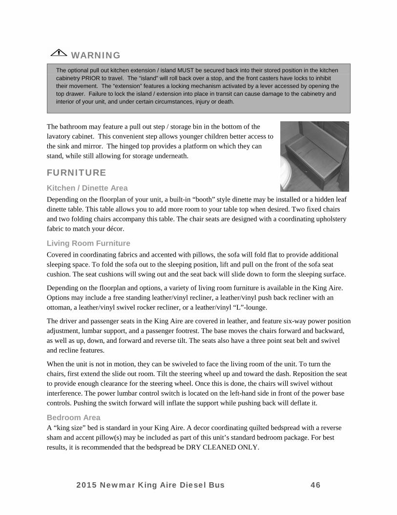
WARNING
The optional pull out kitchen extension / island MUST be secured back into their stored position in the kitchen cabinetry PRIOR to travel. The “island” will roll back over a stop, and the front casters have locks to inhibit their movement. The “extension” features a locking mechanism activated by a lever accessed by opening the top drawer. Failure to lock the island / extension into place in transit can cause damage to the cabinetry and interior of your unit, and under certain circumstances, injury or death.
The bathroom may feature a pull out step / storage bin in the bottom of the lavatory cabinet. This convenient step allows younger children better access to the sink and mirror. The hinged top provides a platform on which they can stand, while still allowing for storage underneath.
FURNITURE
Kitchen / Dinette Area Depending on the floorplan of your unit, a built-in “booth” style dinette may be installed or a hidden leaf dinette table. This table allows you to add more room to your table top when desired. Two fixed chairs and two folding chairs accompany this table. The chair seats are designed with a coordinating upholstery fabric to match your décor.
Living Room Furniture Covered in coordinating fabrics and accented with pillows, the sofa will fold flat to provide additional sleeping space. To fold the sofa out to the sleeping position, lift and pull on the front of the sofa seat cushion. The seat cushions will swing out and the seat back will slide down to form the sleeping surface.
Depending on the floorplan and options, a variety of living room furniture is available in the King Aire. Options may include a free standing leather/vinyl recliner, a leather/vinyl push back recliner with an ottoman, a leather/vinyl swivel rocker recliner, or a leather/vinyl “L”-lounge.
The driver and passenger seats in the King Aire are covered in leather, and feature six-way power position adjustment, lumbar support, and a passenger footrest. The base moves the chairs forward and backward, as well as up, down, and forward and reverse tilt. The seats also have a three point seat belt and swivel and recline features.
When the unit is not in motion, they can be swiveled to face the living room of the unit. To turn the chairs, first extend the slide out room. Tilt the steering wheel up and toward the dash. Reposition the seat to provide enough clearance for the steering wheel. Once this is done, the chairs will swivel without interference. The power lumbar control switch is located on the left-hand side in front of the power base controls. Pushing the switch forward will inflate the support while pushing back will deflate it.
Bedroom Area A “king size” bed is standard in your King Aire. A decor coordinating quilted bedspread with a reverse sham and accent pillow(s) may be included as part of this unit’s standard bedroom package. For best results, it is recommended that the bedspread be DRY CLEANED ONLY.
2015 Newmar King Aire Diesel Bus 46
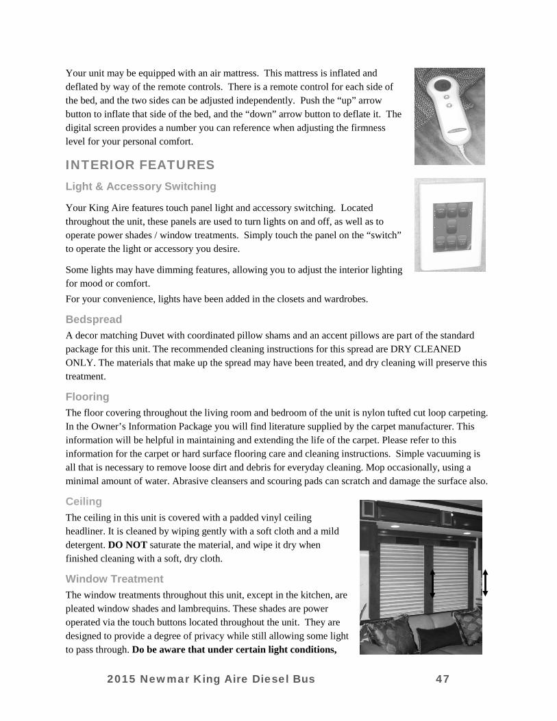
Your unit may be equipped with an air mattress. This mattress is inflated and deflated by way of the remote controls. There is a remote control for each side of the bed, and the two sides can be adjusted independently. Push the “up” arrow button to inflate that side of the bed, and the “down” arrow button to deflate it. The digital screen provides a number you can reference when adjusting the firmness level for your personal comfort.
INTERIOR FEATURES
Light & Accessory Switching
Your King Aire features touch panel light and accessory switching. Located throughout the unit, these panels are used to turn lights on and off, as well as to operate power shades / window treatments. Simply touch the panel on the “switch” to operate the light or accessory you desire.
Some lights may have dimming features, allowing you to adjust the interior lighting for mood or comfort. For your convenience, lights have been added in the closets and wardrobes.
Bedspread A decor matching Duvet with coordinated pillow shams and an accent pillows are part of the standard package for this unit. The recommended cleaning instructions for this spread are DRY CLEANED ONLY. The materials that make up the spread may have been treated, and dry cleaning will preserve this treatment.
Flooring The floor covering throughout the living room and bedroom of the unit is nylon tufted cut loop carpeting. In the Owner’s Information Package you will find literature supplied by the carpet manufacturer. This information will be helpful in maintaining and extending the life of the carpet. Please refer to this information for the carpet or hard surface flooring care and cleaning instructions. Simple vacuuming is all that is necessary to remove loose dirt and debris for everyday cleaning. Mop occasionally, using a minimal amount of water. Abrasive cleansers and scouring pads can scratch and damage the surface also.
Ceiling The ceiling in this unit is covered with a padded vinyl ceiling headliner. It is cleaned by wiping gently with a soft cloth and a mild detergent. DO NOT saturate the material, and wipe it dry when finished cleaning with a soft, dry cloth.
Window Treatment The window treatments throughout this unit, except in the kitchen, are pleated window shades and lambrequins. These shades are power operated via the touch buttons located throughout the unit. They are designed to provide a degree of privacy while still allowing some light to pass through. Do be aware that under certain light conditions,
2015 Newmar King Aire Diesel Bus 47

shadows and silhouettes can be cast on them and visible from the exterior of the unit. If any curtains are installed in this unit, cleaning instructions are DRY CLEAN ONLY. Water-based products are not recommended for cleaning fabrics. Water-based products may cause excessive shrinkage or fading.
Very little to no light passes through it. It is generally used in the evening or when more privacy is desired, though under certain light conditions, it can cast shadows and silhouettes. If any curtains are installed in this unit, cleaning instructions are DRY CLEAN ONLY. Water-based products are not recommended for cleaning fabrics. Water-based products may cause excessive shrinkage or fading.
Safe Located under the bed base is a built in fire resistant “safe box / file cabinet”. This is accessed by raising the bed base / mattress platform. The key for the lock is included with your unit at the time of delivery.
2015 Newmar King Aire Diesel Bus 48
CHAPTER 5 SLIDE OUT FEATURES
WARNING
Read the following slide out room instructions before activating the switch. Do not allow children to operate the slide out. Do not allow any person to place their arms, legs, body or head between any point of the lock arms, slide out fascia, interior walls, exterior walls, objects, or floor, as serious injury or death could result. Any adjustments, or repairs, must be made only by “NEWMAR” qualified personnel. Always check the interior and exterior of the coach for objects, or persons, that are in the path of the slide out when extending or retracting the room. Always check the roof to be sure any objects, or debris, are removed before retracting the room.
CAUTION
It is recommended that the leveling jacks be extended and the unit level before operating the slide out. Note: This slide out can be operated without utilizing the leveling system, but is recommended to have the unit as level as possible.
Your unit is equipped with at least one power slide out room. It is important that you read and understand ALL directions, both in this Owners Guide, and on ALL the labels affixed inside your unit PRIOR to operating your slide out room(s).
Your unit will contain labels with very specific operating and safety information. There are a number of precautions that MUST be observed every time the rooms will either be extended or retracted. For your personal safety, and to prevent potential damage to the slide out mechanism and room, it is paramount that these directions be followed completely. Slide out operation has changed for all RV’s after 2006, and it is important that you understand the operation procedure completely and observe all safety precautions to insure safe, proper operation.
All Slide Out labels contain the following warning:
WARNING Do not allow children to operate the slide out. Do not place arms, legs, body or head between any pinch point of the lock arms, slide out fascia, interior walls, exterior walls, objects, or floor, as serious injury or death could result. Any adjustments, or repairs, must be made only by “NEWMAR” qualified personnel. Always check the interior and exterior of the coach for objects, or persons, that are in the path of the slide out when extending or retracting the room. Always check the roof to be sure any objects, or debris, are removed before retracting the room.
2015 Newmar King Aire Diesel Bus 49
General Instructions
IMPORTANT
The slide out room should be inspected for alignment every six (6) months. If alignment is necessary, have the room adjusted.
IMPORTANT
The slide out room can be stopped at any time by releasing the slide out switch. If the slide out room stops before reaching the full “OUT” or “IN” position, the slide out controller may need adjustment. To adjust the slide out controller, turn the adjustment screw clockwise to increase the power and counter-clockwise to decrease the power. Move the adjustment screw in small increments. Try moving the slide out room again. Use caution. There is a potential for component or structural damage if the screw is adjusted too high. This screw does not adjust the slide out room speed. It sets the amount of power required to move the room against the mechanical stops.
Operating the Slide Out Room Your unit is equipped with Power Locking Arms for the slide out rooms. Designed specifically for this application, these mechanisms automatically “lock” the slide out rooms to the sidewalls of the RV when the room is fully retracted, securing the room in place and providing a positive seal. The operation of the locking mechanism is totally automatic, and begins when you press the button to extend or retract the slide out room.
WARNING
Before extending the slide out, make certain that there is a minimum of five (5) feet of clear space on the slide outside of the unit. Prior to extending the room, be sure to unlock the slide out locking arms. Make sure there are no obstructions either inside or outside the unit that may interfere with the slide out extension. Tree branches, bushes or telephone poles can cause extensive damage to the exterior of the unit.
To extend the room, make certain the coach is plugged into shore power or is under generator power, then press and hold the slide out button. The power lock arms will retract into their housings, and the room will begin to extend approximately 10 seconds after the voice begins. It will continue to run until it reaches the end of its travel, or until you release the slide out switch.
To retract the room, press the slide out button as described above, holding it for the duration of room travel. The room will retract, and at the end of its travel the slide out motor will stop, and the Power Locking Arms will deploy, securing the room to the sidewall of the unit. Please note that you must hold the slide out button down during this entire cycle.
The power locks require a minimum of 9 volts DC to operate. In the event of a loss of power, or if the voltage dips below the minimum requirements, the locks will not extend or retract automatically.
For proper operation of the room and locks battery voltage must be maintained above the minimum requirements. Also please note that there is a safety “lock out” system incorporated in the slide out electronics that prevents the room from operating when the ignition key is “on”. The automatic locking arms require no maintenance, and should be serviced as necessary only by a qualified technician.
2015 Newmar King Aire Diesel Bus 50

MANUAL EXTENSION AND RETRACTION The slide out room may be manually retracted. Before attempting to manually extend or retract a slide out room, please contact your servicing dealer or call Newmar Customer Support at 1-800-731-8300.
IMPORTANT It is important to clean the slide out rollers under the floor regularly as dirt may adhere to the rubber coating on these rollers and cause damage to hard surface flooring. Such damage is not covered under warranty. These rollers may leave indentations in carpeting, linoleum and other flooring. This condition is normal and does not warrant flooring replacement.
IMPORTANT
The TRANS-TORQUE bushing must be re-tightened to re-couple the slide out gear motor before moving the coach. This will hold the slide out room in place. The correct torque on the 11/2" TRANS-TORQUE bushing is 110 foot pounds maximum. The correct torque on the 11/2" TRANS-TORQUE bushing of the K-900 motor (center shaft motor) is 145 foot pounds maximum. Slide outs with either the center or end mounted motors can be moved by pushing the room the full length of its travel in either direction. This method will require the assistance of at least two people.
2015 Newmar King Aire Diesel Bus 51
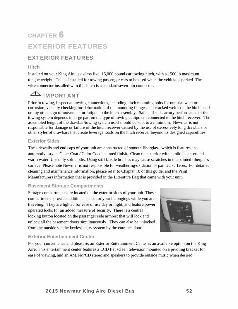
CHAPTER 6
EXTERIOR FEATURES
EXTERIOR FEATURES
Hitch Installed on your King Aire is a class five, 15,000 pound car towing hitch, with a 1500 lb maximum tongue weight. This is installed for towing passenger cars to be used when the vehicle is parked. The wire connector installed with this hitch is a standard seven-pin connector.
IMPORTANT Prior to towing, inspect all towing connections, including hitch mounting bolts for unusual wear or corrosion, visually checking for deformation of the mounting flanges and cracked welds on the hitch itself or any other sign of movement or fatigue in the hitch assembly. Safe and satisfactory performance of the towing system depends in large part on the type of towing equipment connected to the hitch receiver. The assembled length of the drawbar/towing system used should be kept to a minimum. Newmar is not responsible for damage or failure of the hitch receiver caused by the use of excessively long drawbars or other styles of drawbars that create leverage loads on the hitch receiver beyond its designed capabilities.
Exterior Sides The sidewalls and end caps of your unit are constructed of smooth fiberglass, which is features an automotive style “Clear-Coat / Color Coat” painted finish. Clean the exterior with a mild cleanser and warm water. Use only soft cloths. Using stiff bristle brushes may cause scratches in the painted fiberglass surface. Please note Newmar is not responsible for weathering/oxidation of painted surfaces. For detailed cleaning and maintenance information, please refer to Chapter 10 of this guide, and the Paint Manufacturers information that is provided in the Literature Bag that came with your unit.
Basement Storage Compartments Storage compartments are located on the exterior sides of your unit. These compartments provide additional space for your belongings while you are traveling. They are lighted for ease of use day or night, and feature power operated locks for an added measure of security. There is a central locking button located on the passenger side armrest that will lock and unlock all the basement doors simultaneously. They can also be unlocked from the outside via the keyless entry system by the entrance door.
Exterior Entertainment Center For your convenience and pleasure, an Exterior Entertainment Center is an available option on the King Aire. This entertainment center features a LCD flat screen television mounted on a pivoting bracket for ease of viewing, and an AM/FM/CD stereo and speakers to provide outside music when desired.
2015 Newmar King Aire Diesel Bus 52
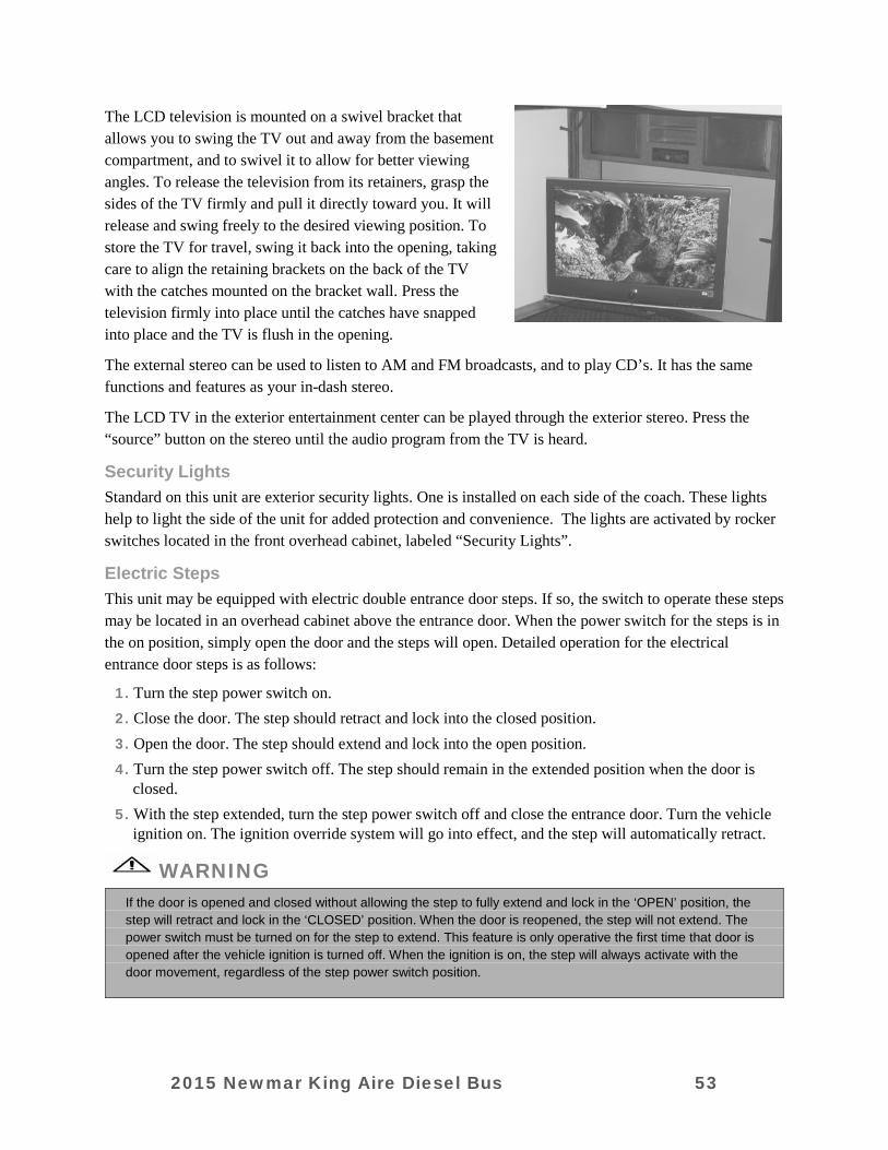
The LCD television is mounted on a swivel bracket that allows you to swing the TV out and away from the basement compartment, and to swivel it to allow for better viewing angles. To release the television from its retainers, grasp the sides of the TV firmly and pull it directly toward you. It will release and swing freely to the desired viewing position. To store the TV for travel, swing it back into the opening, taking care to align the retaining brackets on the back of the TV with the catches mounted on the bracket wall. Press the television firmly into place until the catches have snapped into place and the TV is flush in the opening.
The external stereo can be used to listen to AM and FM broadcasts, and to play CD’s. It has the same functions and features as your in-dash stereo.
The LCD TV in the exterior entertainment center can be played through the exterior stereo. Press the “source” button on the stereo until the audio program from the TV is heard.
Security Lights Standard on this unit are exterior security lights. One is installed on each side of the coach. These lights help to light the side of the unit for added protection and convenience. The lights are activated by rocker switches located in the front overhead cabinet, labeled “Security Lights”.
Electric Steps This unit may be equipped with electric double entrance door steps. If so, the switch to operate these steps may be located in an overhead cabinet above the entrance door. When the power switch for the steps is in the on position, simply open the door and the steps will open. Detailed operation for the electrical entrance door steps is as follows:
1. Turn the step power switch on. 2. Close the door. The step should retract and lock into the closed position. 3. Open the door. The step should extend and lock into the open position. 4. Turn the step power switch off. The step should remain in the extended position when the door is
closed. 5. With the step extended, turn the step power switch off and close the entrance door. Turn the vehicle
ignition on. The ignition override system will go into effect, and the step will automatically retract.
WARNING
If the door is opened and closed without allowing the step to fully extend and lock in the ‘OPEN’ position, the step will retract and lock in the ‘CLOSED’ position. When the door is reopened, the step will not extend. The power switch must be turned on for the step to extend. This feature is only operative the first time that door is opened after the vehicle ignition is turned off. When the ignition is on, the step will always activate with the door movement, regardless of the step power switch position.
2015 Newmar King Aire Diesel Bus 53

CAUTION
If the vehicle is driven with the step in the extended position, there is the possibility of causing major damage to both the step and the vehicle.
6. Turn the vehicle ignition off and open the door. The step will extend and lock in the open position.
Mirrors This vehicle is equipped with side mounted two-part exterior rear view mirrors. The top portion of the mirror is flat, providing conventional reflected views down the sides of the RV, while the bottom portion is convex to provide an expanded view, helping to eliminate blind spots. Make sure the seat is positioned for proper vehicle control, and then adjust the mirrors for maximum rear visibility prior to driving.
These mirrors are adjusted by using the mirror control panel located on the driver’s side arm rest area forward of the cup holder. Select the mirror to be adjusted by rocking the switch to either “L” or “R” of that mirror, then use the arrow buttons on the panel to move the mirror up, down, in or out. Please note that only the upper, flat portion of the mirror can be moved remotely by these switches. The convex lower portion is adjustable manually. These mirrors also contain heating elements to defog or de-ice the mirror glass during cold weather operation. The ON/OFF switch for this feature is located by the adjustment control.
IMPORTANT
Objects viewed in convex mirrors appear smaller and farther away than they actually are.
Rear Vision System Your King Aire is equipped with a “Rear Vision” package that allows you to access and view the exterior (and interior) of your unit through a number of video cameras located in and around your coach.
The cameras are accessed through the left hand touch screen Sony monitor in the dash.
The primary camera view is from the rear of the unit. A camera mounted on the rear cap of your motorhome faces down and back to help you when backing the unit, when observing traffic in transit, or when checking on a vehicle you are towing behind your unit. This camera comes on automatically any time your RV transmission is in reverse. It can also be manually selected using the “Camera Select” button on the dash switch panel below the monitor.
There are five additional cameras in this “Rear Vision” system. As with the rear vision camera, all of these cameras can be manually selected using the “Camera Select” switch on the dash below the monitor.
2015 Newmar King Aire Diesel Bus 54
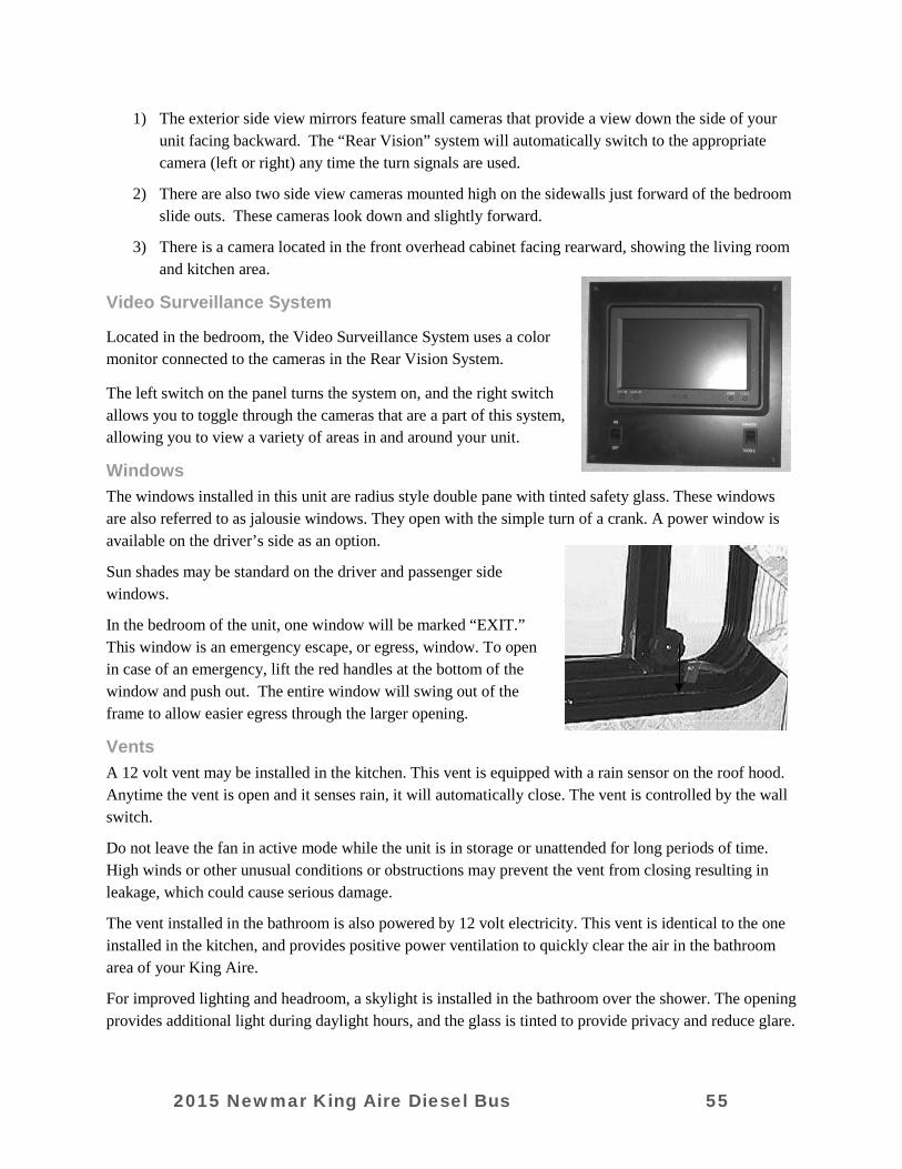
1) The exterior side view mirrors feature small cameras that provide a view down the side of your unit facing backward. The “Rear Vision” system will automatically switch to the appropriate camera (left or right) any time the turn signals are used.
2) There are also two side view cameras mounted high on the sidewalls just forward of the bedroom slide outs. These cameras look down and slightly forward.
3) There is a camera located in the front overhead cabinet facing rearward, showing the living room and kitchen area.
Video Surveillance System
Located in the bedroom, the Video Surveillance System uses a color monitor connected to the cameras in the Rear Vision System.
The left switch on the panel turns the system on, and the right switch allows you to toggle through the cameras that are a part of this system, allowing you to view a variety of areas in and around your unit.
Windows The windows installed in this unit are radius style double pane with tinted safety glass. These windows are also referred to as jalousie windows. They open with the simple turn of a crank. A power window is available on the driver’s side as an option.
Sun shades may be standard on the driver and passenger side windows.
In the bedroom of the unit, one window will be marked “EXIT.” This window is an emergency escape, or egress, window. To open in case of an emergency, lift the red handles at the bottom of the window and push out. The entire window will swing out of the frame to allow easier egress through the larger opening.
Vents A 12 volt vent may be installed in the kitchen. This vent is equipped with a rain sensor on the roof hood. Anytime the vent is open and it senses rain, it will automatically close. The vent is controlled by the wall switch.
Do not leave the fan in active mode while the unit is in storage or unattended for long periods of time. High winds or other unusual conditions or obstructions may prevent the vent from closing resulting in leakage, which could cause serious damage.
The vent installed in the bathroom is also powered by 12 volt electricity. This vent is identical to the one installed in the kitchen, and provides positive power ventilation to quickly clear the air in the bathroom area of your King Aire.
For improved lighting and headroom, a skylight is installed in the bathroom over the shower. The opening provides additional light during daylight hours, and the glass is tinted to provide privacy and reduce glare.
2015 Newmar King Aire Diesel Bus 55

Doors The front entrance door is equipped with a dead bolt lock for added security and a power flush stepwell cover. When the door is opened fully, the “posi-lock” feature will automatically hold the door in the full open position. To close the door from the full open position, push past the resistance the locking feature offers and the door will close. For your safety and convenience a lighted, acrylic assist handle has been installed at the entrance door of the unit.
AWNINGS
IMPORTANT
It is important prior to extending you awnings that you inspect the areas beside and around your unit where the awning will extend to insure proper clearance.
IMPORTANT
The power awnings on your King Aire all operate on 110 volt AC current. The unit must be plugged into shore power or have the generator running to deploy or retract your awnings.
Side Awnings Power side patio awnings are standard on your King Aire. Extension and retraction is controlled by a switches located in the front overhead cabinet. To operate, follow these instructions:
Extending and Retracting Turn the power “ON” to the awning. Press the “Extend” button on the awning switch panel; the awning will fully extend. To retract the awning, press the “Retract” button on the panel. Be sure to allow the awning to fully extend or retract when operating it. The mechanism is designed for best support at full extension, and fastens securely in place for travel when fully retracted.
Manual Retraction In the event that electricity is not available in your unit, the power awning can be retracted manually.
On top of the awning (at the back of the front awning, and the front of the rear awning) there is a “Manual Override” that you can employ to retract the awning (see illustration). The retraction port is always on the motor end of the awning.
IMPORTANT
If you have a wind sensor mounted in this location, you will need to remove the Phillips head screw attaching the wind sensor, and set the wind sensor aside.
2015 Newmar King Aire Diesel Bus 56
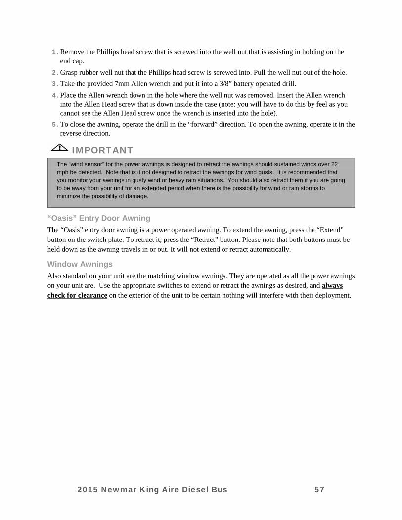
1. Remove the Phillips head screw that is screwed into the well nut that is assisting in holding on the end cap.
2. Grasp rubber well nut that the Phillips head screw is screwed into. Pull the well nut out of the hole. 3. Take the provided 7mm Allen wrench and put it into a 3/8” battery operated drill. 4. Place the Allen wrench down in the hole where the well nut was removed. Insert the Allen wrench
into the Allen Head screw that is down inside the case (note: you will have to do this by feel as you cannot see the Allen Head screw once the wrench is inserted into the hole).
5. To close the awning, operate the drill in the “forward” direction. To open the awning, operate it in the reverse direction.
IMPORTANT
The “wind sensor” for the power awnings is designed to retract the awnings should sustained winds over 22 mph be detected. Note that is it not designed to retract the awnings for wind gusts. It is recommended that you monitor your awnings in gusty wind or heavy rain situations. You should also retract them if you are going to be away from your unit for an extended period when there is the possibility for wind or rain storms to minimize the possibility of damage.
“Oasis” Entry Door Awning The “Oasis” entry door awning is a power operated awning. To extend the awning, press the “Extend” button on the switch plate. To retract it, press the “Retract” button. Please note that both buttons must be held down as the awning travels in or out. It will not extend or retract automatically.
Window Awnings Also standard on your unit are the matching window awnings. They are operated as all the power awnings on your unit are. Use the appropriate switches to extend or retract the awnings as desired, and always check for clearance on the exterior of the unit to be certain nothing will interfere with their deployment.
2015 Newmar King Aire Diesel Bus 57
CHAPTER 7
ELECTRICAL FEATURES
GENERAL INFORMATION There are two electrical systems in your coach. They are the 12 volt DC system and the 110 volt AC system. Most standard appliances require 110 volt electricity while the majority of the lighting used in recreation vehicles is powered by 12 volt electricity. The power for the 12 volt system is supplied by the coach batteries, which are charged by the charge circuit in the inverter, or the engine alternator while in transit. The power for the 110 volt systems is supplied by the power cord when the unit is connected to an outside power source or by the generator. The inverter can also supply 110 volt power. It will transform 12 volt “DC” (Direct Current) electricity from the batteries into 110 volt AC (“Alternating Current”) power for basic appliances and accessories.
CAUTION
Failure to turn off the 120 volt appliances when starting or stopping the generator may damage the transfer switch and/or electrical appliances.
WARNING
Use of “Adapter” cords with the RV shore power cord. All Newmar units are manufactured with either a 30 or 50 amp electrical breaker box and electrical system. A unit with a shore power cord that has 3 prongs on it has 30 amp service; if the shore power cord has 4 prongs, it has 50 amp service. To provide the correct amperage into the RV, and to assure the operation is as designed, it is important that they be plugged into the correct type of receptacle. NEWMAR CORPORATION DOES NOT RECOMMEND USE OF “ADAPTER”, “CHEATER”, OR “DOG BONE” STYLE CONNECTORS THAT WILL MODIFY THE EXISTING SHORE POWER CORD TO A DIFFERENT STYLE OF OUTLET. USE OF THIS TYPE OF ADAPTER WILL GREATLY REDUCE THE AMOUNT OF AVAILABLE CURRENT IN THE UNIT, AS WELL AS CREATES THE POTENTIAL FOR ELECTRICAL FAILURE AND / OR FIRE. NEWMAR CORPORATION CANNOT ASSUME LIABILITY FOR FAILURES OCCURRING TO THE RV, ITS ELECTRICAL SYSTEM, OR ANY OF ITS COMPONENTS FROM THE USE OF ANY ELECTRICAL ADAPTER.
110 VOLT AC SYSTEM The 110 volt AC system in your unit is designed to provide safe power for operating AC powered appliances and accessories in your unit. It is wired as a 50 amp, single phase system. Incoming power is supplied to your unit from one of three sources:
Shore Power Cord The “shore power” cord supplies electricity to the coach via the connection at the campground post.
2015 Newmar King Aire Diesel Bus 58
Generator The generator supplies AC current to your coach when running. You generator is hard wired into the “Automatic Transfer Switch”, which routes power into the breaker box and beyond to the accessories it powers.
Inverter The inverter is designed to invert DC power from the house batteries into AC to operate the applicable appliances and accessories. The inverter also has a charge circuit that will recharge the house batteries when AC is present from the shore power cord or generator.
Incoming AC Power The incoming power from the generator or shore power cord is routed to the main breaker panel. The source is selected by way of an “Automatic Transfer Switch”. When 110 VAC is present on the incoming legs, the Automatic Transfer Switch will select it as the power source, and will switch automatically to it.
IMPORTANT
If power is supplied to the system by both the Genset and shore power cord, the automatic transfer switch will select the generator input by default. By prioritizing the generator circuit, power will always be available as long as the generator will run, regardless whether there is access to shore power. If the unit is plugged into a shore power outlet at a campground, and the generator is started, the automatic transfer switch will default to the generator circuit.
To connect the unit to 110 volt shore power, first make sure all of the breakers are in the off position. This is done to avoid a power surge. Unwind the power cord from the electrical compartment. The standard electrical service in this unit is 50 amps with a flexible cord. Check to make sure the pins in the outlet are oriented correctly, that they match the power cable, and that they are in good condition. If there is a circuit breaker switch at the plug, it should be turned OFF before making the connection. Insert the plug completely into the outlet and turn the circuit breaker on. Close and lock the electrical compartment door to keep the contents clean, dry, and secure. Close the cover on the power box, if equipped, to avoid an unintended disconnection and to keep contents clean. Switch the main breaker to the ON position. The 120 volt system will energize all 110 volt circuits and outlets when the main breaker is turned on.
IMPORTANT
It is important to inspect the shore power cord before and after each use. If the cord or plug shows any signs of damage, either from abrasion or heat, or if the pins are loose, or the insulation is damaged or pulled back at all, it should be inspected by a qualified technician for potential replacement. NEVER use a shore power cord that has exposed wires or signs of heat damage (melting insulation or cover, misaligned pins, etc.).
110 VAC Breaker Boxes Main Breaker Box The 110 volt and 12 volt breaker boxes are generally located in the bathroom cabinetry. Circuit breakers and fuses are installed to protect the electrical system from overloading. Do not attempt to change the circuitry or add appliances yourself. Please consult an authorized Newmar Service Center.
2015 Newmar King Aire Diesel Bus 59
Inverter “Sub-panel” Breaker Box The circuits that the inverter supplies power to are independently protected in a smaller “sub” panel located adjacent to the main breaker box. This panel is powered by the inverter. When the unit is plugged into shore power or the generator is running, the current passes through the inverter to supply power to these circuits.
When there is no external AC power source, the inverter powers these circuits with the house batteries. Note that every appliance and accessories in your unit is not on the Inverter “Sub” Breaker box. Only those appliances in the Inverter “Sub” Box will be powered by the inverter.
Generator The generator in your unit is located between the front frame rails, and is mounted on a hydraulic cradle that will extend or retract the generator at the touch of a button. It is wired into the “Automatic Transfer Switch” and will power all the 110 volt AC circuits in your King Aire. The generator can be started from the dash switch, or remotely started at the generator itself.
Located on the generator remote start panel (at the generator) are two main breakers for the two output legs of the generator wiring. Please note that on startup, there is a momentary delay in the “Automatic Transfer Switch” engaging to pass the electricity on from the Genset.
The generator in your new King Aire runs on the same diesel fuel as your main engine. The diesel fuel is drawn through a separate supply tube that is positioned in the tank in a manner that will not allow the generator to draw fuel and run if the tank level dips below the ¼ level.
Please refer to the generator manufacturers operating guide for specific information on maintaining your new Genset. Regular oil changes and other maintenance performed at the prescribed intervals will greatly extend the life of your generator.
Inverter Your King Aire is equipped with a 2800 Watt “Pure Sine Wave” inverter. An inverter changes DC power from the house batteries into AC current to operate most of your appliances.
When 110 VAC is present from the generator or shore power, internal switching in the inverter passes the electricity through to the appliances it controls, and turns on a charge circuit to recharge the batteries. The inverter is controlled by the remote panel located in the front overhead cabinet.
The ME inverter / charger has two modes of operation: “Inverter” mode (providing power to the appliances from the house batteries), and “AC” mode (running from shore power or if your Genset is running).
When your inverter is in the “AC” mode, it passes power directly to your appliances, as well as recharges the batteries using a three stage battery charger (“Bulk”, “Absorption”, and “Float”). This approach to battery charging provides rapid and complete charging cycles without placing undue stress on the batteries. Inverter operation is completely automatic.
2015 Newmar King Aire Diesel Bus 60
IMPORTANT
Inverters draw power from the “house” batteries to provide current to most of the appliances and accessories in your unit without having to plug into shore power or run your generator. Because they use DC power from the batteries to do that, energy consumption from those batteries is high, and increases significantly as more appliances are added to the load. To extend battery life, minimize the number of appliances operating at any given time. All AC operated appliances have a label attached to tell how much power they consume. Be sure allow sufficient time for recovery / recharging between battery use cycles.
IMPORTANT
High battery voltage may be caused by excessive voltage from the alternator, solar panels, or another external charge source. Be sure to correct the cause of the overcharging condition to prevent damage to the batteries and electronic equipment in your King Aire. The inverter must be manually restarted after this fault.
12 VOLT DC SYSTEM
General Information There are two separate 12 volt DC electrical systems on your King Aire; one for the “chassis” portion, and the other for the “house” portion.
The “chassis” electrical system uses DC voltage to operate chassis related electrical accessories and lights, such as the headlamps, dash instrumentation, engine starting and management circuitry, and so on. This system includes a set of chassis batteries, and is charged in transit by the alternator. The chassis batteries have a disconnect switch located in the rear engine compartment.
The “house” electrical system uses DC voltage to operate all the house related DC lights and accessories, such as the interior lighting, ceiling vents and fans, slide outs, the water pump, and so on. The house electrical system also supplies the power (through the house batteries) for the inverter to operate. When 110 AC current is present, the inverter has a charge circuit that engages to charge the house batteries.
Though separate in operation, the two DC electrical systems are tied together through a battery isolator circuit. This circuitry is designed to keep the systems separated under most operating circumstances, but still allows them to be tied together under certain conditions. This is accomplished through a component called the Bi-Directional Isolator Relay Delay (BIRD). This component allows the two separate battery systems to be tied together for charging purposes or for “boosting” purposes if one set of batteries is low.
In transit, the alternator on the engine is the power source for charging batteries. The function of the “BIRD” allows the chassis batteries to be recharged off of the power coming from the alternator. Once the chassis batteries have been recharged (approximately 13.3 VDC), the “BIRD” will turn on circuitry that will then allow the house batteries to be charged in transit by the alternator. This allows both sets of batteries to charge while the coach is in transit.
When the RV is parked (with the engine off), and is connected to 110 VAC power (either generator or shore power), the “charge circuitry” in the inverter will engage, and will charge the house batteries. Once the house batteries have reached full charge (approximately 13.3 VDC), the “BIRD” will again engage circuitry that connects the two sets of batteries together, allowing the charge circuit in the inverter to
2015 Newmar King Aire Diesel Bus 61
charge the chassis batteries as well. This “Bi-Directional” operation works to keep both sets of batteries charged to capacity, regardless of whether it is in transit, or parked with incoming AC current.
12 Volt DC Circuit Protection House Circuits The “house” fuse panel is located in a cabinet in the bathroom. This panel contains fuses for most of the Newmar installed 12 volt DC accessories, including interior lighting, vents and fans, and so on. The fuse panel uses conventional “spade” type automotive DC fuses. Fuse amperage is labeled on the end of the fuse for easy viewing and replacement.
IMPORTANT
NEVER replace a fuse with a higher amp capacity fuse than was originally installed. This compromises the circuit protection by allowing more amperage to flow through than the circuit was designed for, and could lead to failure of the component being operated, overheating of the wiring, or fire. Always use the same amperage fuse when replacement is necessary.
The “dash” fuse panel is located in the left front exterior compartment. This panel contains relays and fuses that protect Newmar installed dash accessories, including dash lights, blower fan, auxiliary accessory ports, and more. This panel uses standard “spade” type automotive fuses. The relays on this circuit board are not replaceable; they are permanently mounted to the circuit board and should be inspected only by a qualified technician prior to having any work done to them.
Chassis Circuit Protection The chassis 12 volt DC circuit protection is located in two primary areas on your King Aire. First, the front electrical panel, with fuses and relays, is located in the LF basement compartment, along with the Newmar dash fuse panel.
This panel consists of fuses and relays that control engine start up and operating functions. It is recommended that these circuits be serviced ONLY by a trained Spartan chassis technician.
The first basement compartment aft of the right rear tires houses the chassis diagnostic center. This service area contains diagnostic ports, relays, and circuit protection for the engine and transmission. This compartment should be serviced ONLY by a trained Spartan chassis technician.
Batteries As previously mentioned, your King Aire has two different sets of batteries. One set of batteries operates the Newmar installed “house” lights and accessories, and the other set starts the engine and operates the “chassis” electrical systems. Though similar in function, they are distinctly different battery types and arrangements.
Replacement batteries should be the same as was replaced. Any time one battery in a set of batteries is to be replaced, it is important to have all the batteries in the system tested to assure all are okay. If one defective battery is replaced, while leaving another weak or defective battery, lowered performance, or ultimately damaging the new or good batteries can be the result.
2015 Newmar King Aire Diesel Bus 62
IMPORTANT
Charging batteries give off gasses as the fluids inside “boil”. Because of this, it is critical to check the battery fluid levels regularly, particularly after extended periods of heavy use. Be sure to top off any battery that is showing signs of depleted fluid levels.
House Batteries The standard battery arrangement in the King Aire is a set of four (4) BCI “group size” GC-2 6 volt DC batteries, delivering a 450 amp hour reserve. If your King Aire is the “all electric” model, there will be eight (8) of the same batteries, significantly increasing the available reserve. Douglas batteries for operation of the chassis electrical systems. The King Aire comes with two (2) “group size” 37 - 12 VDC batteries with 960 cranking amps.
The All Electric King Aire If your King Aire is equipped with the “All Electric” option, it is designed to operate solely on electricity, and will have no Propane gas tank or Propane fired appliances. Additional changes will include a larger bank of batteries (as previously mentioned), an electric range, and an electric refrigerator.
Note that because this unit does not have Propane, the refrigerator needs 110 AC current all the time to operate. Because of that, the refrigerator circuit is on the inverter. This is ONLY the case in the “all electric” King Aire. In all other King Aire models, where Propane gas is available, the refrigerators operate on Propane gas as well as electricity, so the need for inverter power to the refer is not necessary.
2015 Newmar King Aire Diesel Bus 63

CHAPTER 8
PLUMBING & BATH FEATURES
FRESH WATER SYSTEM
IMPORTANT
Ease of operation was the key element in the design of the water compartment and plumbing in your unit. It is very important that you read and understand all the operating instructions for the plumbing system prior to using your unit. Failure to connect and operate the system correctly can result in damage that is not covered by the Newmar limited warranty.
IMPORTANT
The fresh water system in your King Aire is designed to operate at a maximum of 60 PSI. Water pressure levels above that can damage the fresh water plumbing in your unit. If your travels take you to a destination where water pressure is above 60 psi, you must install a pressure regulator to reduce the incoming pressure, or fill the fresh water tank and use the internal water pump to supply water to your unit.
Kitchen Sink The kitchen sink installed in your unit is a double-bowl design equipped with two sink covers to provide additional counter space when not in use. Cleaning care consists of washing with mild detergents and a soft cloth. Avoid using “SOS.” type cleaning pads because they may scratch the surface. The faucet in the kitchen is a single-handle faucet with a pullout spout.
Bath Sink, Shower & Accessories Use care when cleaning the bathroom sinks to prevent scratching the surface. The bathroom accessories include two towel bars and a tissue holder. The faucet in the bathroom consists of a metal body with a brass finish. The shower installed is a combination fiberglass tub/shower with a glass shower door. The white tub faucet with shower head, hose and bracket coordinate with the sink faucet. An optional assist handle may be installed in the tub/shower.
Multiplex Touch Screen Monitor Panel The Multiplex Touch Screen Monitor Panel allows you to check the approximate levels in the fresh, gray, and black water holding tanks, as well as Propane gas level (on units with the “All Electric” option, the monitor panel will not have an Propane gas reading).
There is an additional Touch Screen Monitor Panel located in the basement water compartment. This additional screen is designed just to give readings for all the holding tanks in the unit. No other functions (inverter, Genset, HVAC, etc.) controlled by the main Multiplex Touch Screen are accessible by the auxiliary Multiplex Touch Screen Monitor Panels.
Water Pump Operation Your King Aire has a fully self-contained fresh water system with a fresh water storage tank, and a “demand” style 12 volt DC electric water pump. This pump is designed to build pressure in the fresh
2015 Newmar King Aire Diesel Bus 64
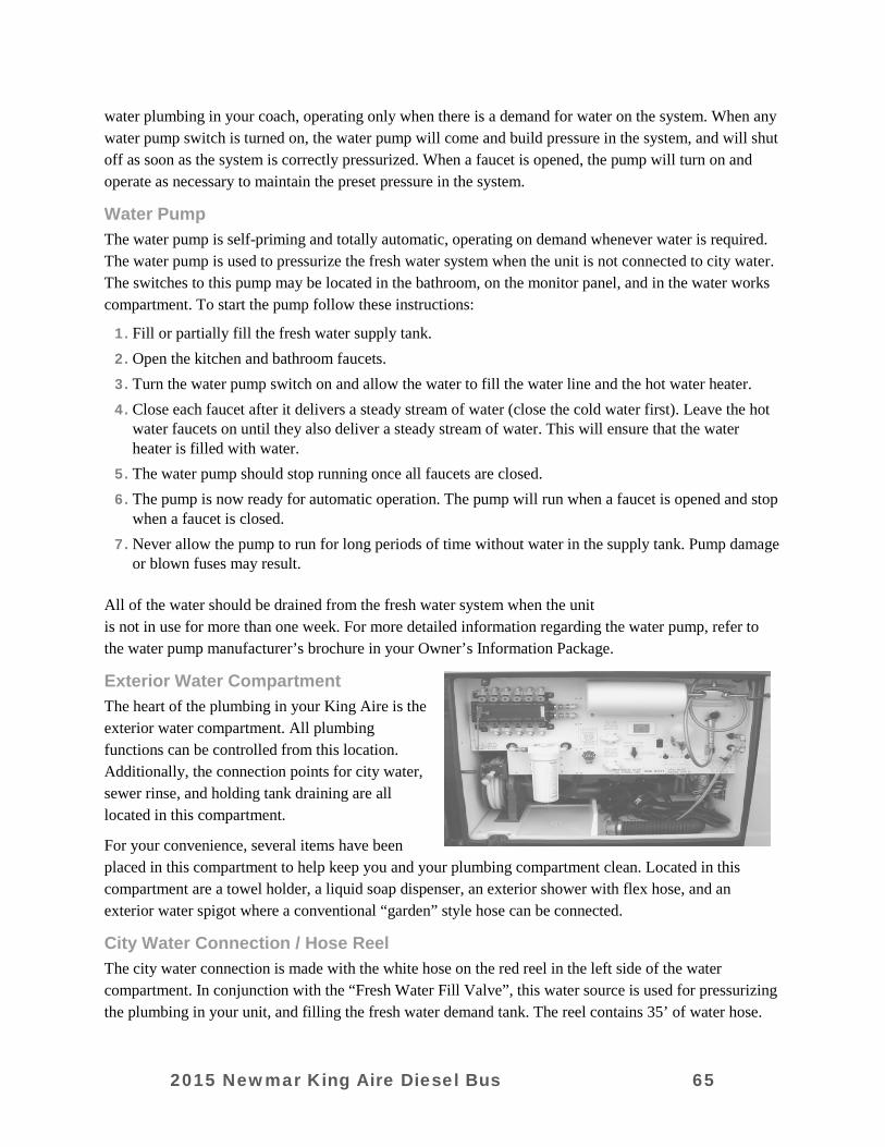
water plumbing in your coach, operating only when there is a demand for water on the system. When any water pump switch is turned on, the water pump will come and build pressure in the system, and will shut off as soon as the system is correctly pressurized. When a faucet is opened, the pump will turn on and operate as necessary to maintain the preset pressure in the system.
Water Pump The water pump is self-priming and totally automatic, operating on demand whenever water is required. The water pump is used to pressurize the fresh water system when the unit is not connected to city water. The switches to this pump may be located in the bathroom, on the monitor panel, and in the water works compartment. To start the pump follow these instructions:
1. Fill or partially fill the fresh water supply tank. 2. Open the kitchen and bathroom faucets. 3. Turn the water pump switch on and allow the water to fill the water line and the hot water heater. 4. Close each faucet after it delivers a steady stream of water (close the cold water first). Leave the hot
water faucets on until they also deliver a steady stream of water. This will ensure that the water heater is filled with water.
5. The water pump should stop running once all faucets are closed. 6. The pump is now ready for automatic operation. The pump will run when a faucet is opened and stop
when a faucet is closed. 7. Never allow the pump to run for long periods of time without water in the supply tank. Pump damage
or blown fuses may result. All of the water should be drained from the fresh water system when the unit is not in use for more than one week. For more detailed information regarding the water pump, refer to the water pump manufacturer’s brochure in your Owner’s Information Package.
Exterior Water Compartment The heart of the plumbing in your King Aire is the exterior water compartment. All plumbing functions can be controlled from this location. Additionally, the connection points for city water, sewer rinse, and holding tank draining are all located in this compartment.
For your convenience, several items have been placed in this compartment to help keep you and your plumbing compartment clean. Located in this compartment are a towel holder, a liquid soap dispenser, an exterior shower with flex hose, and an exterior water spigot where a conventional “garden” style hose can be connected.
City Water Connection / Hose Reel The city water connection is made with the white hose on the red reel in the left side of the water compartment. In conjunction with the “Fresh Water Fill Valve”, this water source is used for pressurizing the plumbing in your unit, and filling the fresh water demand tank. The reel contains 35’ of water hose.
2015 Newmar King Aire Diesel Bus 65
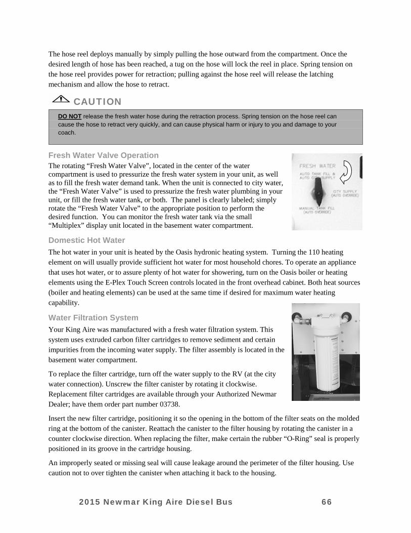
The hose reel deploys manually by simply pulling the hose outward from the compartment. Once the desired length of hose has been reached, a tug on the hose will lock the reel in place. Spring tension on the hose reel provides power for retraction; pulling against the hose reel will release the latching mechanism and allow the hose to retract.
CAUTION
DO NOT release the fresh water hose during the retraction process. Spring tension on the hose reel can cause the hose to retract very quickly, and can cause physical harm or injury to you and damage to your coach.
Fresh Water Valve Operation The rotating “Fresh Water Valve”, located in the center of the water compartment is used to pressurize the fresh water system in your unit, as well as to fill the fresh water demand tank. When the unit is connected to city water, the “Fresh Water Valve” is used to pressurize the fresh water plumbing in your unit, or fill the fresh water tank, or both. The panel is clearly labeled; simply rotate the “Fresh Water Valve” to the appropriate position to perform the desired function. You can monitor the fresh water tank via the small “Multiplex” display unit located in the basement water compartment.
Domestic Hot Water The hot water in your unit is heated by the Oasis hydronic heating system. Turning the 110 heating element on will usually provide sufficient hot water for most household chores. To operate an appliance that uses hot water, or to assure plenty of hot water for showering, turn on the Oasis boiler or heating elements using the E-Plex Touch Screen controls located in the front overhead cabinet. Both heat sources (boiler and heating elements) can be used at the same time if desired for maximum water heating capability.
Water Filtration System Your King Aire was manufactured with a fresh water filtration system. This system uses extruded carbon filter cartridges to remove sediment and certain impurities from the incoming water supply. The filter assembly is located in the basement water compartment.
To replace the filter cartridge, turn off the water supply to the RV (at the city water connection). Unscrew the filter canister by rotating it clockwise. Replacement filter cartridges are available through your Authorized Newmar Dealer; have them order part number 03738.
Insert the new filter cartridge, positioning it so the opening in the bottom of the filter seats on the molded ring at the bottom of the canister. Reattach the canister to the filter housing by rotating the canister in a counter clockwise direction. When replacing the filter, make certain the rubber “O-Ring” seal is properly positioned in its groove in the cartridge housing.
An improperly seated or missing seal will cause leakage around the perimeter of the filter housing. Use caution not to over tighten the canister when attaching it back to the housing.
2015 Newmar King Aire Diesel Bus 66

IMPORTANT
DO NOT ALLOW WATER TO FREEZE IN THE WATER FILTER CANISTER. Freezing will crack and permanently damage the filter housing and associated plumbing. ALWAYS REMOVE THE FILTER CARTRIDGE PRIOR TO WINTERIZATION.
Water Distribution Manifold Located in the upper left hand corner of the exterior water compartment is the water distribution manifold. The primary hot and cold water lines for the unit fed to this distribution center, and through a series of valves, supply water to the multiple plumbing systems in the unit.
In addition to offering greater organization and more balanced flow to the fresh water system in your unit, this distribution manifold offers the flexibility to allow you to shut off sections of the system while still using others. The blue knobs at the top are cold water supply valves; the red ones at the bottom are hot water supply valves. A tool is supplied with which you can open and close the valves as or if necessary.
WASTE WATER SYSTEM General Information The waste drainage system was designed to provide adequate and safe storage and/or disposal of waste materials. All of the materials used in the making of this system are tested by a nationally recognized testing laboratory. The drainage system uses plastic piping and fittings connected to the sinks, toilet, and holding tanks. This provides for their drainage to an outside termination. The unit should be reasonably level for best operation of the system. There are two separate waste systems. The gray water system is for waste water from the sinks and shower. The black water system is generally for sewage waste from the stool. Each tank has its own control valve, and both tanks drain through the sewer drain hose.
Toilet The standard toilet in your unit is a china stool. The toilet operates with water from either the fresh water tank with the water pump on or the city water supply. Before using the stool, add water to the bottom of the tank. Refer to the “BLACK WATER TANK” instructions in this chapter. The stool flushes waste directly into the black water holding tank. The stool uses high velocity water injection to produce a swirl effect in the bowl. The greatest problem that causes stool solids to build up in the holding tank is lack of liquids. When using your stool, it is wise to fill the stool 3/4 full of water.
This will help to wash the solids away from directly below the stool and to ensure complete dumping of the holding tank. To add water to the stool bowl, press the button for “power fill” until the desired water level is reached. To flush the stool, push down on the lever until the water swirls. A small amount of water should remain in the bowl.
The stool should be cleaned regularly for maximum sanitation and operational efficiency. Clean the toilet bowl with a mild bathroom cleaner. Do not use chlorine or caustic chemicals, such as laundry bleach or drain opening types, as they will damage the seals in the toilet and dump valves.
2015 Newmar King Aire Diesel Bus 67
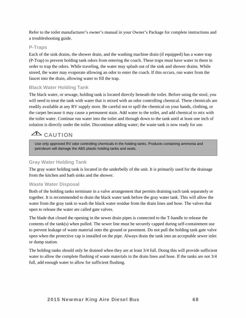
Refer to the toilet manufacturer’s owner’s manual in your Owner’s Package for complete instructions and a troubleshooting guide.
P-Traps Each of the sink drains, the shower drain, and the washing machine drain (if equipped) has a water trap (P-Trap) to prevent holding tank odors from entering the coach. These traps must have water in them in order to trap the odors. While traveling, the water may splash out of the sink and shower drains. While stored, the water may evaporate allowing an odor to enter the coach. If this occurs, run water from the faucet into the drain, allowing water to fill the trap.
Black Water Holding Tank The black water, or sewage, holding tank is located directly beneath the toilet. Before using the stool, you will need to treat the tank with water that is mixed with an odor controlling chemical. These chemicals are readily available at any RV supply store. Be careful not to spill the chemical on your hands, clothing, or the carpet because it may cause a permanent stain. Add water to the toilet, and add chemical to mix with the toilet water. Continue run water into the toilet and through down to the tank until at least one inch of solution is directly under the toilet. Discontinue adding water; the waste tank is now ready for use.
CAUTION
Use only approved RV odor controlling chemicals in the holding tanks. Products containing ammonia and petroleum will damage the ABS plastic holding tanks and seals.
Gray Water Holding Tank The gray water holding tank is located in the underbelly of the unit. It is primarily used for the drainage from the kitchen and bath sinks and the shower.
Waste Water Disposal Both of the holding tanks terminate in a valve arrangement that permits draining each tank separately or together. It is recommended to drain the black water tank before the gray water tank. This will allow the water from the gray tank to wash the black water residue from the drain lines and hose. The valves that open to release the water are called gate valves.
The blade that closed the opening in the sewer drain pipes is connected to the T-handle to release the contents of the tank(s) when pulled. The sewer line must be securely capped during self-containment use to prevent leakage of waste material onto the ground or pavement. Do not pull the holding tank gate valve open when the protective cap is installed on the pipe. Always drain the tank into an acceptable sewer inlet or dump station.
The holding tanks should only be drained when they are at least 3/4 full. Doing this will provide sufficient water to allow the complete flushing of waste materials in the drain lines and hose. If the tanks are not 3/4 full, add enough water to allow for sufficient flushing.
2015 Newmar King Aire Diesel Bus 68
WARNING
Holding tanks are an enclosed sewer system and must be drained into an approved dump station. Both black and gray water holding tanks must be drained and rinsed thoroughly on a regular basis in order to prevent the accumulation of harmful or toxic materials. Whenever possible, drain the holding tanks prior to traveling. The carrying capacity of your unit will be reduced if water is left in the black or gray tanks.
To empty the waste water tanks, connect the adapter to the drain hose. Use the adapter supplied with your unit. If the adapter is lost or broken, one can be purchased from any RV supply store. Once you have placed the adapter on the drain hose, it can remain there for the life of the hose. One end of the hose threads up through the hole in the bottom of the service compartment, and the other end of the hose feeds into the sewer at the dump station. Unscrew the cap off the drain. Connect the hose with the adapter in place to the drain fitting. Open the gate valve all the way by pulling on the T-handle. The tank will start to drain as soon as the T-handle is pulled. After you have drained the black water tank, immediately drain the gray water tank. Doing this helps to flush the black water from the sewage hose. When both of the tanks are empty, flush them with a fresh water rinse before you close the valves. The gray tanks are easily flushed by pouring a couple of gallons of water into a sink drain. The drain outlet is engineered for quick release of the drain hose adapter. Always close the gate valves and secure the end cap to prevent leakage while in transit. After draining the black water tank, it is recommended to add a few gallons of water and a holding tank deodorant (such as Thetford Aqua-Kem) to help control the odor and break down the solids. Follow the instructions given on the holding tank deodorant package.
When using dump stations for draining the holding tanks, please keep other travelers in mind by practicing good housekeeping. Leave the dump stations in good order. Above all, do not pollute.
Camping with Sewer Hook-Up When camping at parks with sewer hook-up, it is important to keep the black water holding tank gate valve closed at all times, except when dumping. The gray tank can be kept open while hooked to a sewer connection but again, the black water tank must be kept closed. This is done so that an ample supply of liquid remains in the tank to provide a smooth flow through the gate and drain valve when dumping. Sufficient liquid in the tank causes a swirling action that should take any accumulated solid wastes with it. Accumulation of solid wastes in the black water tank can be avoided by keeping the gate valve closed when connected to the sewer hook-up. If the valve is left open, solid wastes may accumulate in the tank. This may eventually result in costly repairs.
CAUTION
The gray tank valve must be in the open position when operating the optional washing machine.
Sewage Tank Rinse To aid in maintenance and cleaning, the sewage tank on your King Aire is equipped with a “Sewage Tank Rinse”. This system uses a specially designed spray head permanently located in the sewage tank that cleans the inside of the tank when a water supply is connected.
2015 Newmar King Aire Diesel Bus 69
IMPORTANT
Always drain the sewage tank PRIOR to rinsing. NEVER rinse a sewage tank that is full. The sewage drain MUST be open while rinsing the sewage tank, and the drain hose MUST be positioned to drain into an approved sewage dump station. Failure to open the valve will cause the sewage tank to fill with water, and can cause damage to your plumbing and interior.
The Sewage Tank Rinse should have its own dedicated water supply hose. NEVER use a hose that will be used for drinking or other uses. Attach the hose to the external water supply, then to the Sewage Tank Rinse connection. Attach the sewer drain hose to the outlet, and place the open end in an approved sewer “Dump Station”. Open the sewer drain gate valve. Turn on the external water supply to rinse the tank. Allow the water to rinse the tank for a minimum of 3 – 5 minutes to insure it is clean.
Winterization It is critical to winterize the plumbing in your unit any time it is going to be either stored in temperatures below freezing, or used only on a limited basis in cold weather. Winterization is simply the removal of all of the water from the plumbing system. It also includes adding potable antifreeze to at least portions of the systems (P-Traps) to help prevent freeze damage.
Located in the lower right hand corner of the basement water compartment is a label identifying the steps used to winterize the fresh water system in your King Aire. The label reads as follows:
Drain Fresh Water Tank and Hose Reel Close “Low Point” Hot and Cold Water Valves
Close Top “A” Valve On This Panel Open Valve “B” Below It
Insert Hose into Container of Potable Antifreeze Turn On Water Pump
Open All Faucets Flush Toilet
Open All Drains
WARNING
USE ONLY POTABLE “RV” ANTIFREEZE IN YOUR COACH’S FRESH WATER SYSTEM. AUTOMOTIVE ANTIFREEZE CONTAINS ETHYL GLYCOL, WHICH CAN BE HARMFUL OR FATAL IF INGESTED.
This basic procedure allows you to drain as much of the water out of the system as possible, then adds safe antifreeze to the lines, faucets, p-traps, and tanks. It is important to remember to open all the fresh water drain valves (for the hot and cold water lines, the hose reel, and the fresh water tank) prior to pumping potable antifreeze through the system. Always remember to turn the water pump off when winterization is complete. The following is the detailed procedure for winterizing your King Aire:
1. Remove Filters and bypass the water lines on them (under cabinetry inside unit and in basement water compartment).
2. Open all “Fresh Water” related drains (hot and cold low points and fresh water tank). Drain as much water as possible; close all drain valves.
2015 Newmar King Aire Diesel Bus 70
3. Set “Fill Valve” to “City Water / Auto Tank Fill” position (pointing up). 4. Attach compressed air fitting to “City Water Hose” (Reel). Set air pressure to 40 psi. Apply 40 psi air
pressure to this setting for at least 30 seconds. (This forces water out of any lines and pockets that may not get antifreeze in a later step).
5. Go to exterior refrigerator service panel, and access the water valve / solenoid. Remove supply line and flex line to ice maker. Drain both lines until no more water comes out. The air pressure in the lines will force the existing water in this line out. Reattach water lines and close water supply valve to the refrigerator.
6. Switch “Fill Valve” to the “Manual Fill” position (to force any water out of the additional lines and valves between the tank and water pump). Apply 40 psi of air pressure to this valve position for at least 30 seconds.
7. Turn off air pressure and remove air hose from “City Water” connection. Switch “Fill Valve” to “City Supply / Manual Override” for the rest of the winterization procedure.
8. In the exterior Water Compartment. Engage “Winterization” valves by closing the top “A” valve, and opening the “B” valve below it. Put the end of the clear “winterization” hose in a container of RV “Potable” Antifreeze. Turn on the water pump.
NOTE: APPROXIMATELY 5 – 7 GALLONS OF POTABLE RV ANTIFREEZE ARE REQUIRED TO WINTERIZE A KING AIRE.
9. Start with the farthest faucet from the water compartment (usually the kitchen sink faucet). Open every valve (don’t forget drinking water dispensers and both hot and cold sides of the faucet) and run until RV antifreeze flows freely from each. Close that faucet and move to the next faucet until all have been winterized. DO NOT forget the interior and exterior showers, and the toilet.
10. Winterize appliances as necessary: A. Winterize the dish washer (if so equipped) by running the appliance through a partial “rinse”
cycle. Potable antifreeze will run into the wash drawer (where the dishes are), allowing antifreeze to the fill and drain areas of the appliance. It is important to run the entire rinse cycle so that the fill valves and drain valves and lines receive antifreeze. Note that this appliance only has a single “hot” water connection.
B. Winterize the Washer / Drier (“separates” or single unit) by running a complete rinse cycle in both hot and cold settings. Once the washer has drained the antifreeze, turn the appliance off, lift lid, and add approximately one gallon of RV antifreeze to wash tub.
C. The ice maker was winterized during the initial steps of the procedure.
Sanitizing To assure complete disinfecting of your fresh water system, it is recommended that the following procedure be followed on a new system, on one that has not been used for a length of time, or one that may have become contaminated. This procedure is also recommended before & after long periods of storage, such as over the winter months:
1. Drain the fresh water tank by opening the drain valves. There is one valve per water tank. All of the faucets should be in the closed or off position.
2. Prepare a chlorine solution using one gallon of water and 1⁄4 cup of chlorine bleach (5% sodium hypo-chlorite solution). Prepare enough of the chlorine solution to administer one gallon of solution for every 15 gallons of tank capacity. For sanitizing this unit, prepare 4 - 1/2 gallons of the chlorine
2015 Newmar King Aire Diesel Bus 71
solution. This mixture puts a 50 PPM (parts per million) residual chlorine concentration in the water system that will act as a quick kill dosage for harmful bacteria, viruses and slime forming organisms. Concentrations higher than 50 PPM may damage the water lines and/or tank.
3. Once the fresh water tank is empty, close the drain valves on the water tank. 4. Remove the “whole house” filter element from the housing in the water compartment, and fill the
housing with the chlorine solution. Re-attached the housing and pump the solution into the tank. Repeat this process until the correct amount of solution is in the tank. Turn the tank fill valve from city water to tank fill. Turn on the water pump until all of the solution is pumped into the fresh water tank.
5. Turn off the water pump. Close the valve to the solution. Open the valve from the tank to the water pump. Fill the water tank with the city water tank fill (or by using the same method as was used to put the sanitizing solution into the tank). Remove the water filter (from the drink dispenser faucet, if installed) and install the by-pass pipe to allow the sanitizing solution access to the faucet. Open each faucet in turn including the kitchen faucet, bath faucet, inside and outside shower, turning on both the hot and cold, and flushing the stool until all of the air has been purged from the pipes and the water runs freely. The entire system will then be filled with the sanitizing solution.
6. Allow the 50 PPM disinfecting solution to stand in the system at least four hours. Drain the system and flush with fresh water. The water system needs to be flushed with clean water repeatedly, if necessary, until there is no chlorine taste or smell left in the system. To remove any excessive chlorine taste or odor that might remain, prepare a solution of one quart vinegar to five gallons of water. Allow this solution to agitate in the tank by vehicle motion. Drain the solution and refill the tank with clean water.
IMPORTANT
Make sure the chlorine bleach solution is thoroughly and completely purged from the plumbing before using the fresh water system. Also, never use alternative cleansers; only potable materials may be used in your fresh water plumbing system.
2015 Newmar King Aire Diesel Bus 72
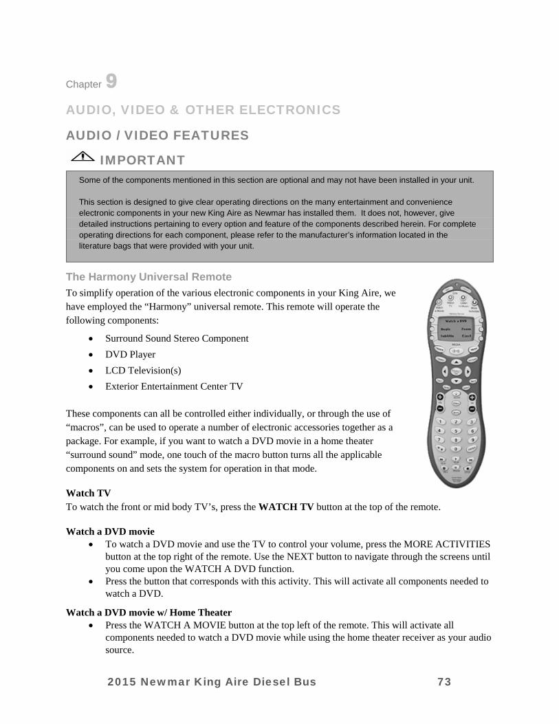
Chapter 9
AUDIO, VIDEO & OTHER ELECTRONICS
AUDIO / VIDEO FEATURES
IMPORTANT Some of the components mentioned in this section are optional and may not have been installed in your unit. This section is designed to give clear operating directions on the many entertainment and convenience electronic components in your new King Aire as Newmar has installed them. It does not, however, give detailed instructions pertaining to every option and feature of the components described herein. For complete operating directions for each component, please refer to the manufacturer’s information located in the literature bags that were provided with your unit.
The Harmony Universal Remote To simplify operation of the various electronic components in your King Aire, we have employed the “Harmony” universal remote. This remote will operate the following components:
• Surround Sound Stereo Component • DVD Player • LCD Television(s) • Exterior Entertainment Center TV
These components can all be controlled either individually, or through the use of “macros”, can be used to operate a number of electronic accessories together as a package. For example, if you want to watch a DVD movie in a home theater “surround sound” mode, one touch of the macro button turns all the applicable components on and sets the system for operation in that mode.
Watch TV To watch the front or mid body TV’s, press the WATCH TV button at the top of the remote.
Watch a DVD movie • To watch a DVD movie and use the TV to control your volume, press the MORE ACTIVITIES
button at the top right of the remote. Use the NEXT button to navigate through the screens until you come upon the WATCH A DVD function.
• Press the button that corresponds with this activity. This will activate all components needed to watch a DVD.
Watch a DVD movie w/ Home Theater • Press the WATCH A MOVIE button at the top left of the remote. This will activate all
components needed to watch a DVD movie while using the home theater receiver as your audio source.
2015 Newmar King Aire Diesel Bus 73

Listen to CD • Press the LISTEN TO MUSIC button on the top of the remote. This will activate all
components necessary to listen to your CD’s.
Listen to Radio • Press the MORE ACTIVITIES button at the top right of the remote. Use the NEXT button to
navigate through the screens until you come upon the LISTEN TO RADIO function. Press the button that corresponds with this activity. This will activate all components needed to listen to a CD.
If you have any problems, or if something is not functioning correctly, please press the HELP button. This will walk you through the steps necessary to make your entertainment system function properly. For more information on operating this remote please refer to the owner’s manual or go to www.harmonyremote.com
IMPORTANT The Harmony Universal Remote will control all of the functions of the Video selector Box except turning the power on or off.
LED TV Your new King Aire has been equipped with at least one LED television. It can be operated either independently, or as part of a system when using the Harmony remote. When operating the TV independently, it can be manipulated through either the controls on the TV, or with the Sony supplied remote control.
To operate the TV independently of the system, press the power button on the front, or use the remote to power the TV up. Once the TV has been turned on, use the input selector on the TV to choose the desired programming.
IMPORTANT TV’s in the front overhead cabinet will not operate when in transit. Federal regulations require these TV’s be inoperative while the vehicle is in use, so the power supply to this TV is switched off automatically when the ignition is on.
The LED TV(s) in your unit are HD (High Definition) compatible, meaning they are capable of displaying the resolution and clarity of High Definition broadcasts and video sources.
Bedroom TV In the bedroom you will find an LED TV. This TV offers HD (High Definition) compatible, meaning it is capable of displaying the resolution and clarity of High Definition broadcasts and video sources. Please refer to the Manufacturers Owners Guide that accompanied your unit for detailed instructions on operating the many features and functions of your new TV.
2015 Newmar King Aire Diesel Bus 74

Surround Sound Theater System The “Surround Sound” Home Theater has been incorporated into your King Aire to bring the movie experience “to life” by placing you in the middle of the action. Located throughout your unit are five speakers and a subwoofer to deliver the dynamic, crystal clear digital sound previously only available in theaters.
Exterior Entertainment Center
For your convenience and pleasure, an Exterior Entertainment Center is an available option on the King Aire. This entertainment center features an LCD flat screen television mounted on a pivoting bracket for ease of viewing, and an AM/FM/CD stereo and speakers to provide outside music when desired. The LCD television is mounted on a swivel bracket that allows you to swing the TV out and away from the basement compartment, and to swivel it to allow for better viewing angles. To release the television from its retainers, grasp the sides of the TV firmly and pull it directly toward you. It will release and swing freely to the desired viewing position. To store the TV for travel, swing it back into the opening, taking that it is fully latched.
IMPORTANT The electronics used in the Exterior Entertainment Center are not designed for use in wet weather. The TV should be stored securely in the “travel” position and the basement door closed during rain or other adverse weather conditions. Caution should also be exercised when washing the exterior of your King Aire to make sure high pressure water does not enter the compartment. Spraying high pressure water at the seal between the doors can cause leaks, and potentially damage the electronics housed in this compartment.
The external stereo can be used to listen to AM and FM broadcasts, and to play CD’s. It has the same functions and features as your in-dash stereo.
The LCD TV in the exterior entertainment center can be played through the exterior stereo. Press the “source” button on the stereo until the audio program from the TV is heard. For detailed operating instructions, please see the stereo manufacturers handbook located in the literature bag that came with your unit.
Power Lift Antenna Your unit is equipped with a Winegard television antenna that features a power lift mechanism to raise and lower the antennae mast. To operate the system, locate the switch panel in the passenger side front overhead cabinet.
When using the antennae, raise and lower it to full extension. Once the antenna is fully extended, it can be rotated to the position that provides optimum signal reception. In rural or fringe areas where reception may be poor or weak, the antennae head had a signal amplifier built in. To turn this amplifier on, use the “Antennae Booster” button on the video selector box.
2015 Newmar King Aire Diesel Bus 75
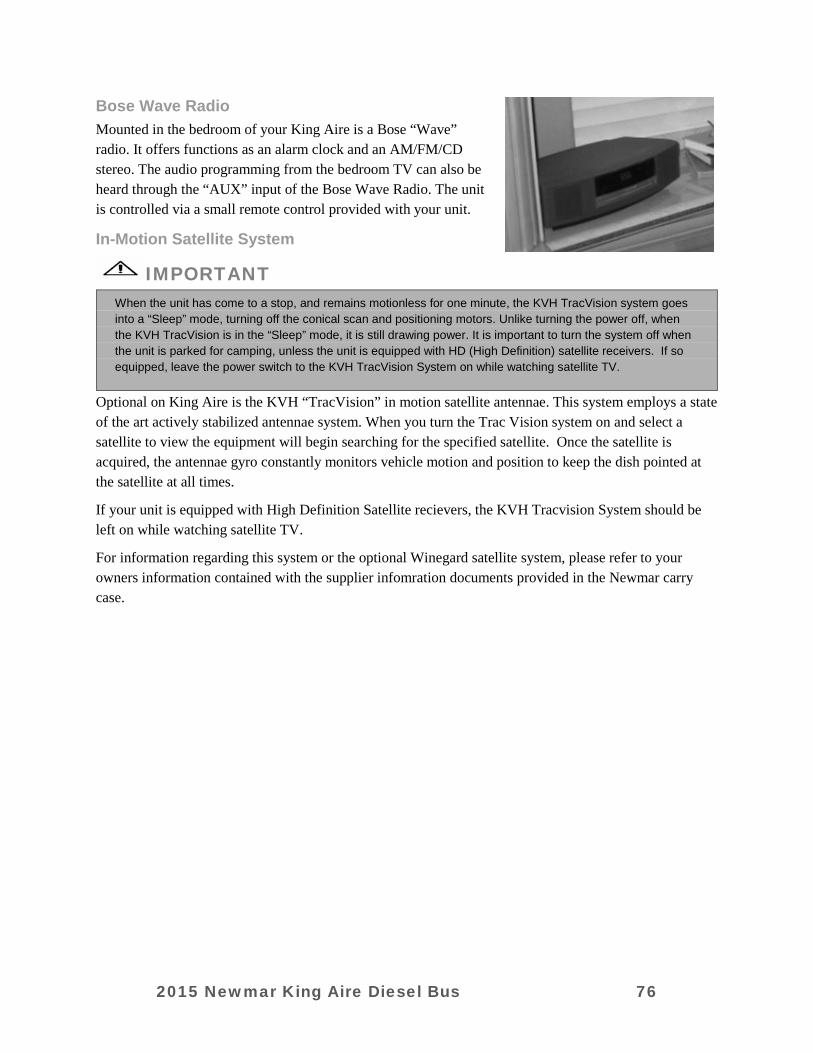
Bose Wave Radio Mounted in the bedroom of your King Aire is a Bose “Wave” radio. It offers functions as an alarm clock and an AM/FM/CD stereo. The audio programming from the bedroom TV can also be heard through the “AUX” input of the Bose Wave Radio. The unit is controlled via a small remote control provided with your unit.
In-Motion Satellite System
IMPORTANT When the unit has come to a stop, and remains motionless for one minute, the KVH TracVision system goes into a “Sleep” mode, turning off the conical scan and positioning motors. Unlike turning the power off, when the KVH TracVision is in the “Sleep” mode, it is still drawing power. It is important to turn the system off when the unit is parked for camping, unless the unit is equipped with HD (High Definition) satellite receivers. If so equipped, leave the power switch to the KVH TracVision System on while watching satellite TV.
Optional on King Aire is the KVH “TracVision” in motion satellite antennae. This system employs a state of the art actively stabilized antennae system. When you turn the Trac Vision system on and select a satellite to view the equipment will begin searching for the specified satellite. Once the satellite is acquired, the antennae gyro constantly monitors vehicle motion and position to keep the dish pointed at the satellite at all times.
If your unit is equipped with High Definition Satellite recievers, the KVH Tracvision System should be left on while watching satellite TV.
For information regarding this system or the optional Winegard satellite system, please refer to your owners information contained with the supplier infomration documents provided in the Newmar carry case.
2015 Newmar King Aire Diesel Bus 76
CHAPTER 10
ROUTINE MAINTENANCE
EXTERIOR CARE
IMPORTANT Damage caused by improper or unapplied maintenance is not covered by your Newmar Limited Warranty.
Washing your RV The clear coat used on all painted Newmar RV’s is a similar to the technology that used by car manufacturers. It is baked in our “state of the art” bake booths which cures the clear coat. The end result is a Masterpiece Finish™ which is the highest quality in the industry. The same care needs to be performed and maintained on your RV exterior surface as on your automobile. • Make sure the RV’s surface temperature is under 90˚ F, and is not in direct sunlight. • Rinse the entire coach to remove all loose dirt and grime. Never hold a pressure washer close to the
surface. Use a fan type spray nozzle, making sure that the water coming out of the gun has a fan and not a single straight stream.
• Most car stores offer mild car wash shampoos that are safe for clear coat finishes. We would recommend using baby shampoo as it will not leave a film on the coach. Adding ½ of a cup of food grade vinegar to the water will boost the cleaning ability of any cleaner and also soften the water. This also helps to minimize water spots. Do not use dish soap, detergents with degreasing agents, or industrial cleaners as they can cause damage to the finish.
• Use 100% cotton or Lambswool pads or wash mitts for washing the painted surfaces of your RV. Use a different mitt for washing the wheels and undercarriage. Please contact your Newmar dealer to order these Newmar parts. (Lambswool pad: 018461; Backer Pad: 018461A; Lambswool mitt: 018464; Extension pole: 018463)
• Change water in your wash bucket often or place a “dirt guard” in bottom of the bucket to keep the cleaning pad or wash mitt free of dirt and debris.
ABSOLUTELY NO BRUSHES SHOULD BE USED ON THE PAINTED SURFACE. USE OF THESE ON YOUR RV’S PAINTED SURFACE WILL CAUSE DAMAGE TO THE FINISH, AS IT WOULD AN AUTOMOBILE FINISH. NEWMAR DOES NOT SUPPORT USING ANY STYLE, TYPE, MATERIAL OF BRUSH EVEN THOUGH IT MAY BE MARKETED AS “RV SAFE” OR “APPROVED.” Damage caused by inappropriate or unapplied maintenance is not covered under warranty as expressed in the Newmar Expressed Limited Written Warranty.
Drying your RV Drying your RV is just as important as washing it. Today’s tap-water and well-water contain many chemicals that could water stain your RV’s finish. After washing, dry your RV with the EZE Squeegee (# 018462) or a clean 100% leather chamois. You can also use fresh Microfiber towels for drying. Please use caution as these towels are made partially with polyester (which is plastic) which can break down over time from extended use and washing, eventually causing damage to the clear coat finish.
2015 Newmar King Aire Diesel Bus 77
IMPORTANT Never use a strong solvent (lacquer thinner or harsh abrasives) on any of the exterior painted surfaces.
Waxing The exterior finish will require a routine waxing. When water will not bead and roll off a freshly washed vehicle, a new coat of wax is needed. Wax not only improves the appearance of the vehicle, but it also protects the finish against oxidation and corrosive materials. The recommended type of wax is one that is compatible with painted or gel-coated fiberglass finishes, and contains a UV (ultra-violet) inhibitor. Buffing with a polishing compound will improve a dull or discolored finish. Review the BASF information provided with your unit for detailed paint care instructions.
IMPORTANT When using a polishing compound that does not contain a wax preservative, reapplying a coat of hard wax after polishing is recommended.
Seals The seals around doors, windows, vents, slide out trim and external seams should be checked at least twice a year. In addition, the roof seams should be inspected twice a year for cracking or peeling. If deterioration is noted during a routine maintenance inspection, reseal the seams or seals with an approved sealant to prevent leaks. It is recommended that a Newmar Authorized Service Center perform these inspections, and reseal when necessary.
Proper Sealants for Application
Proper Sealants for Application
Plas-T-Cote ....................................Metal or fiberglass roof
Surebond #SB-140 .........................Rubber laminated to metal roof and all skylights.
Carlisle #502-LSW .........................Rubber roof over wood Base
Self-Leveling Sealant Silicone Sealant ............................To cover butyl and other sealants; not to be used as the main sealant
Parbond .........................................To seal across tops of windows, etc. on exterior where silicone is not used
Fiberglass Roof
WARNING It is recommended that access, cleaning and maintenance be conducted by a qualified professional at your local dealership. Use caution if working on top of your vehicle. The wet roof surface is extremely slippery.
2015 Newmar King Aire Diesel Bus 78
Your motorhome is equipped with a one piece fiberglass roof. Regular cleaning and maintenance is essential to insuring a long, trouble free life. Before cleaning, it is important that you inspect the sealants and gaskets used to seal components to the roof structure to be certain there is no leakage during the cleaning process. Any cracks or voids in the sealants and seals MUST be repaired prior to spraying the roof with water.
The surface of the fiberglass roof has a gel coat finish that is very similar to the paint on the exterior of your unit. This provides a bright, durable finish that is easy to maintain. Around the perimeter of the roof is a textured area designed to provide better traction while walking on the roof. Great care should be taken when walking on a roof that is wet, as the surface can be extremely slippery.
It is also important to make sure the roof drain catch basin strainers are cleaned and kept free of debris. There are four (4) of them, and they are located at the front and rear ends of the roof gutters, on both the left and right sides.
Clean the roof with a mild detergent and soft brush, such as you would use to wash the exterior of your unit. Stubborn stains, like tree sap or bird droppings, may require additional scrubbing. Do not use harsh chemicals, or any caustic or acid based solutions for cleaning. Standard household cleaners diluted in water and applied with a soft bristle brush provide the best cleaning action. Rinse with clear water, taking care not to spray directly into roof vents, air conditioners, the refrigerator chimney, or and other roof mounted accessories.
Battery Inspection & Care Remember that when batteries are not used for an extended period of time, they may lose their charge. Periodic charging of the batteries during storage of the unit will increase the life of the battery. Check the external condition of the battery periodically. Look for cracks in the cover and case. Check the vent plugs and replace them if they are cracked or broken. Keep the battery clean. Accumulations of acid film and dirt may permit current flow between the terminals, which could drain the battery.
WARNING Remove rings, metal watch bands, and other metal jewelry before working around batteries. Use caution when using metal tools. If a tool contacts a battery terminal or metal connected to it, a short circuit could occur which could cause personal injury, explosion or fire.
CAUTION Disconnect the 120 volt electrical power cord and the negative terminal from the coach batteries before working on the electrical system.
Remember that when batteries are not used for an extended period of time, they may lose their charge. Periodic charging of the batteries during storage of the unit will increase the life of the battery. Check the external condition of the battery periodically. Look for cracks in the cover and case. Check the vent plugs and replace them if they are cracked or broken. Keep the battery clean. Accumulations of acid film and dirt may permit current flow between the terminals, which could drain the battery.
2015 Newmar King Aire Diesel Bus 79
To clean, wash the batteries with a diluted solution of baking soda and water to neutralize any acid present. Rinse thoroughly with clean water. Foaming around the terminals or on top of the battery is a sign that acid is being neutralized. Avoid getting the baking soda solution in the battery. Secure all vent caps. Dry the battery cables and terminals to prevent corrosion. Do not use grease on the bare metal inside the cable terminals as it can act as an insulator, and electricity will not flow through it. A plastic ignition spray will protect the terminals after they have been cleaned.
WARNING Do not allow the battery fluid to contact your skin, eyes, fabric, or painted surfaces. The fluid could cause serious personal injury or property damage. Wear eye protection when working with batteries.
The batteries should be removed and stored in a warm place when not using your motorhome for an extended period of time. Mark the cables, positive and negative, for easy identification. Batteries are not to be stored on concrete floors. If the motorhome is to be stored for a long period of time, it is recommended that all of the batteries inside the unit be removed from clocks, radios, smoke alarms, etc. This will prevent unnecessary drain and corrosion of the batteries. The coach batteries are 6 volt RV/Marine deep cycle batteries. This type of battery consumes water and must be filled periodically. Please be sure to check the battery water level on a regular basis. Consult the owner’s manual supplied by the battery manufacturer.
Alloy Wheels Your motorhome is equipped with Accuride Aluminum “Alloy” Wheels. Below is the manufacturer’s recommended cleaning procedure:
1. Rinse the wheel with high pressure water to remove any debris, grit, or dirt particles. High pressure water is recommended.
2. Use a 100% cotton cloth dipped in a mild soap (dish soap or automotive auto wash soap) to help remove stuck on road dirt and grease.
3. Thoroughly rinse any remaining soap residue from the wheel. 4. Dry the wheel thoroughly with a 100% cotton cloth.
IMPORTANT To insure damage does not occur to your alloy wheels while cleaning, the following list must be adhered to: 1) DO NOT scrub the wheels before rinsing off loose particles with high pressure water; rubbing debris
against the wheel surface will scratch it. 2) DO NOT use synthetic cleaning pads; synthetic cleaning pads can result in streaking on the surface of
the wheel. 3) DO NOT use wire brushes to remove dirt or grime from the wheel surfaces. 4) DO NOT use strong detergents, strong solvents, acidic or alkaline cleaners to clean your alloy wheels.
These solutions can attack the finish on the surface of the wheel, causing damage or dull spots in the finish.
5) DO NOT allow soap solutions to dry on the surface of the wheel; be sure to rinse and thoroughly them after cleaning.
6) DO NOT use polishes or waxes on an Accu-shield aluminum wheel. The finish will maintain its bright, shiny surface for years to come without the need for special polishes.
2015 Newmar King Aire Diesel Bus 80
INTERIOR CARE
WARNING Urea-formaldehyde is used in the productions of particle board, hardwood plywood, and most paneling. Urea-formaldehyde resin may release formaldehyde vapors into the air, which may cause headaches, and in some people, eye, nose and throat irritation. Formaldehyde may intensify some allergies or upper respiratory problems like asthma. Providing proper ventilation as needed by operating the power roof vents and opening windows should reduce the risk of such problems.
IMPORTANT The fading of upholstery, carpet and other interior fabrics is generally caused by excessive sunlight. The drapes, blinds or shades should be kept closed when the vehicle is parked for an extended period of time to minimize the fading. Normal deterioration of appearance items due to wear and/or exposure is not covered by the Newmar Limited Warranty.
Carpet A weekly routine of vacuuming the carpet and fabrics throughout the vehicle is recommended. Doing this will prevent an accumulation of dirt that can detract from the materials appearance and shorten its life. Remember to empty or replace vacuum bags before they become half full. In carpet areas that receive the most sunlight, close the curtains frequently to prevent fading. And act quickly when anything is spilled or dropped on the carpet.
Included in the Owner’s Information Package is the carpet manufacturer’s Carpet Care Guide. The Carpet Care Guide lists detailed information on cleaning soiled areas and removing stains from the carpet installed in the unit.
Fabrics The fabrics used in this motorhome for the bedspread, draperies, headboard and valances contain fire-retardant additives that may be damaged by use of improper cleaning products. Cleaning instructions for these items are DRY CLEAN ONLY. Water-based products are not recommended for cleaning the fabrics in your new unit. Most water-based household cleaning products are not formulated for use on these fabrics and may cause excessive shrinkage or fading. For best results, the fabrics in this unit should be cleaned by a professional carpet and upholstery cleaner.
Spills, spots or stains should be treated as soon as possible to avoid permanent damage. If a spill occurs, blot the fluid with a dry towel. Do not rub the spill. Rubbing may cause the liquid to “set” in the fabric. When attempting to clean a spot or stain, always start from the outside and work inward to avoid spreading it further.
Some stains or soils are extremely difficult or impossible to be removed completely. These should receive immediate, professional attention. Spills, spots, stains or soils are the responsibility of the owner, and are not covered by the Newmar Limited Warranty.
2015 Newmar King Aire Diesel Bus 81
WARNING When cleaning the upholstery and fabric in the unit, do not use lacquer thinner, nail polish remover, laundry soaps or bleach. Never use carbon tetrachloride or gasoline for cleaning purposes. These items may cause damage to the materials being cleaned, and most are highly flammable.
Walls & Ceiling The wall and ceiling coverings should be cleaned periodically to maintain a new appearance. Use a non-abrasive cleaner with a soft cloth on the walls. Do not—
• Use solvents of any kind. Solvents may damage the surface.
Dash In order to keep the dash in like-new condition, follow these guidelines:
Do— • Dust and clean the dash with a soft, damp cloth, or chamois, wiping the surface gently. • Use a mild detergent and lukewarm water. • Dry the surface, after washing and rinsing, by blotting with a damp cloth or chamois. Do Not— • Use harsh chemicals that may damage the dash. • Use cloths containing grit or abrasive particles or kitchen scouring compounds to clean/dust the dash. • Subject the dash to hard, direct blows. • Use boiling water, strong solvents or other materials listed below to clean the dash, as they will
soften the plastic.
Woodwork The wood cabinetry should be cared for with furniture polish to sustain the natural beauty and luster of the wood. This will also keep your cabinetry looking new, and prevent the wood from drying. Use of area rugs and floor mats by the entrance door is recommended to trap dirt. To clean the flooring, begin by vacuuming the floor to remove loose dust and dirt. Then, damp mop the floor using one gallon of clean, warm water with a non-abrasive, soap-free cleaner. The mop should be damp, not dripping. Do not use soap-based cleaners, scouring powders, steel wool, abrasive cleaners, wax or polish on the floor. To remove stubborn spots like shoe polish, oil, tar, markers, scuffs, etc., use a household solvent, acetone or nail polish remover, then wipe with a damp cloth. To remove chocolate, grease, juice or wine, use warm water and a non-abrasive cleaner.
To remove candle wax or chewing gum, carefully scrape off when the material has hardened. For further tips, please see the manufacturer’s information sheet in your Owner’s Information Packet.
Counter Tops To properly care for the countertop in your new unit, always use a heat pad or trivet to protect the surface from hot objects that may mar or damage the surface. Also avoid cutting directly on the surface and avoid
2015 Newmar King Aire Diesel Bus 82
using harsh chemicals on the counter top. Wipe the counter top with a damp cloth to remove water spots. For most dirt and stains, wipe with a damp cloth and use soapy water or ammonia-based cleaners.
Accessories Your motorhome is equipped with brass or brushed nickel light fixtures, bath accessories and faucets. They are cleaned by wiping with a soft, damp cloth. Washing with warm water will remove dry water spots. Do not use cleaners that contain harsh or abrasive chemicals. Alcohol or similar solvents should never be used.
Detectors The CO and Propane detectors (if equipped) are self-contained and DO NOT require any maintenance other than normal cleaning and dusting. The smoke detector installed is 9 volt battery operated. The battery needs to be tested periodically and replaced when necessary. Please check your smoke detector for the manufacturer’s expiration date. When cleaning the case on any of the detectors, use a damp cloth or paper towel. Do not spray cleaners or wax directly into case as it may cause false alarms.
Condensation
IMPORTANT Since surface condensation within the coach cannot be controlled by the manufacturer, damage caused by condensation is not covered by your Newmar Limited Warranty.
Damage may occur to your unit if excessive condensation exists. Accumulation of condensation on surfaces within your unit occurs when warm, moist air contacts a cool surface. It is most evident on the inside of windows. This problem can be controlled by:
1. Slightly opening a window or roof vent to allow the moisture to escape from the unit. 2. A small dehumidifier is also very effective in removing moisture from the air.
IMPORTANT • Condensation levels are highest during times when a person is cooking or taking a shower in the unit, but
these are not the only times condensation is present. • Condensation can migrate through ceiling panels and saturate the fiberglass insulation in your ceiling cavity.
This condition often causes the occupants to believe the recreational vehicle has a roof leak. Walls and ceiling panels may also become wet when the moisture accumulates on these surfaces.
• Newmar Corporation does not recommend the use of any catalytic heaters.
ROUTINE MAINTENANCE
IMPORTANT Always follow the chassis maintenance guidelines found in the chassis manufacturer owner’s manual.
All routine maintenance is the responsibility of the owner and is not covered by the Newmar Limited Warranty. Please note that damage caused by improper or unapplied maintenance is not covered by the Newmar Limited Warranty.
2015 Newmar King Aire Diesel Bus 83
Items supplied by other manufacturers may require specific individual maintenance not listed herein. Please refer to the manufacturers’ suggested maintenance guidelines in the Owner’s Information Packet.
IMPORTANT Cosmetic adjustments and alignments must be performed within the first three (3) months from date of original purchase for warranty consideration. Thereafter, these items are considered routine maintenance.
Monthly • Check battery water level.
Every Three (3) Months • Clean range hood exhaust fan filter and blades. • Check gas lines for leaks with soap solution or leak detector. • Test smoke alarm, carbon monoxide detector and Propane gas detector. • Check operation of windows, latches and hinges. • Clean the roof ducted air conditioner filter(s). • Clean and inspect all door and window seals; reseal where necessary. • Inspect and reseal around the tub and shower area where necessary. • Lubricate the exterior door hinges and latches with a graphite (silicone) lubricant. • Check, clean and tighten battery cables, and inspect batteries for proper fluid level.
Every Six (6) Months • Inspect the slide out for proper seal. If realignment is necessary, please contact an Authorized
Newmar Service Center. • Inspect the exterior rubber slide out seals and apply a UV inhibitor, • Rotate tires as recommended by the tire manufacturer. • Check all gas appliances for proper operation. • Have the Propane system inspected by a qualified technician. • Lubricate the moveable parts on the entrance step.
Annually • Inspection of roof seams and joints should be performed by an Authorized Newmar Service Center.
If resealing is necessary, it is the owner’s responsibility and is not covered by the Newmar Limited Warranty.
• Sanitize the fresh water system. • Wax and buff all gel-coat surfaces on the vehicle as described previously in this chapter.
COLD WEATHER USE Although great care has been taken to build a well-insulated unit, recreational vehicles are not intended for extended use in subfreezing weather without special precautions. When the temperature drops below freezing, the furnace must be turned on to keep the unit warm. Continued use in cold weather will require the unit to be winterized.
2015 Newmar King Aire Diesel Bus 84

2015 SilverLeaf Functional Guide• 2015 SilverLeaf Functional Guide
◦ Introduction▪ RV-C Control System▪ Technical Support
◦ Home◦ AC Power
▪ Load Management▪ Load Status▪ Load Settings
◦ DC Power▪ Magnum Inverter Settings▪ Magnum Inverter Status▪ Xantrex Inverter #1 Settings▪ Xantrex Inverter #2 Settings▪ Xantrex Inverter #2 Advanced Settings
◦ Genset◦ Water◦ Climate◦ Temp◦ Floor Heat◦ Features 1
▪ Clock▪ Alarm Status▪ Virtual Keypad▪ System Diagnostics
◦ Features 2▪ Monitor Configuration▪ Auto Genstart Configuration▪ AC Power History▪ Auto Fill Configuration
© 2014 Copyright Newmar Corporation. All rights reserved. p.1

◦ Features 3▪ Floor Heat Configuration▪ Warnings Configuration▪ Tank Calibration▪ Climate Configuration
◦ Features 4▪ TM102 Configuration▪ Component Versions▪ WiFi Connections▪ Cellular Connection
◦ Features 5▪ WiFi Connections▪ Cellular Connection▪ View Splash Screen▪ Test Touchscreen
◦ Driver Display▪ Home :: Gauges▪ Home :: Configuration▪ HOUSE :: Tanks▪ HOUSE :: Genset▪ HOUSE :: AC Power▪ HOUSE :: DC Power▪ HOUSE :: Floor Heat▪ THERM▪ CHASS▪ TRIP
© 2014 Copyright Newmar Corporation. All rights reserved. p.2
IntroductionOverviewDefines SilverLeaf and provides a basic description of how it works.
What is SilverLeaf?SilverLeaf is a User Interface that coordinates the various systems in the Newmar high-end motor coaches;for example: AC/DC power, HVAC, and water tanks.
How does SilverLeaf work?SilverLeaf is based on the RV-C industry standard for component communications.
Relays Signals to ComponentsThe SilverLeaf system is not the actual controller for the systems within a motor coach. It's just the display that sendsthe signal to tell various components what actions to take.
Independent ModulesThere is no main computer; each of the controlling modules functions independently so when one system is down, theothers continue to operate.
Central LocationThis Interface allows the user to access the control functions for the various systems and make changes from acentralized location.
Control Panel
SilverLeaf can be accessed from the overhead control panel in the cockpit or from the bedroom control panel (optional).Some coaches may also be equipped with a driver control console.
Wireless
The settings can also be adjusted from a tablet computer or a smartphone with the appropriate application. This optionis only available for coaches equipped with the WiFi or cellular modules.
System Status and WarningsThe Interface also displasy system status messages and warnings.
© 2014 Copyright Newmar Corporation. All rights reserved. p.4
RV-C Control SystemExplains the foundation of the SilverLeaf system communications.
FeatureRV-C is the recreational vehicle version of the Bosch Controller Area Network or CAN Bus. This system has been usedin the automotive industry for many years.
ModulesRV-C is a network of modules that share common language and procedures. Some of the modules controlled by theRV-C include:
• AC (110v) and DC (12v) Power• Generators• Water Tanks• Climate• Temperature• Floor Heat
SignalsWhen a module sends a command to the system, it is authenticated to ensure that the message has been receivedcorrectly and is not corrupted in any way. This means that the systems are less likely to malfunction.
Distinguishing CharacteristicA distinguishing characteristic of the RV-C system from older technology is that the RV-C verifies the signals it receivesprior to sending it, where older technology would simply send the signal.
More InformationFor more information regarding the RV-C protocol, please click the image below to see the full PDF article.
© 2014 Copyright Newmar Corporation. All rights reserved. p.5
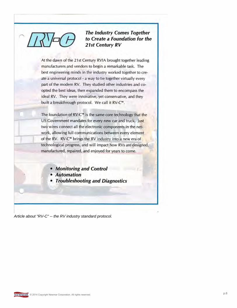
Article about "RV-C" -- the RV industry standard protocol.
© 2014 Copyright Newmar Corporation. All rights reserved. p.6
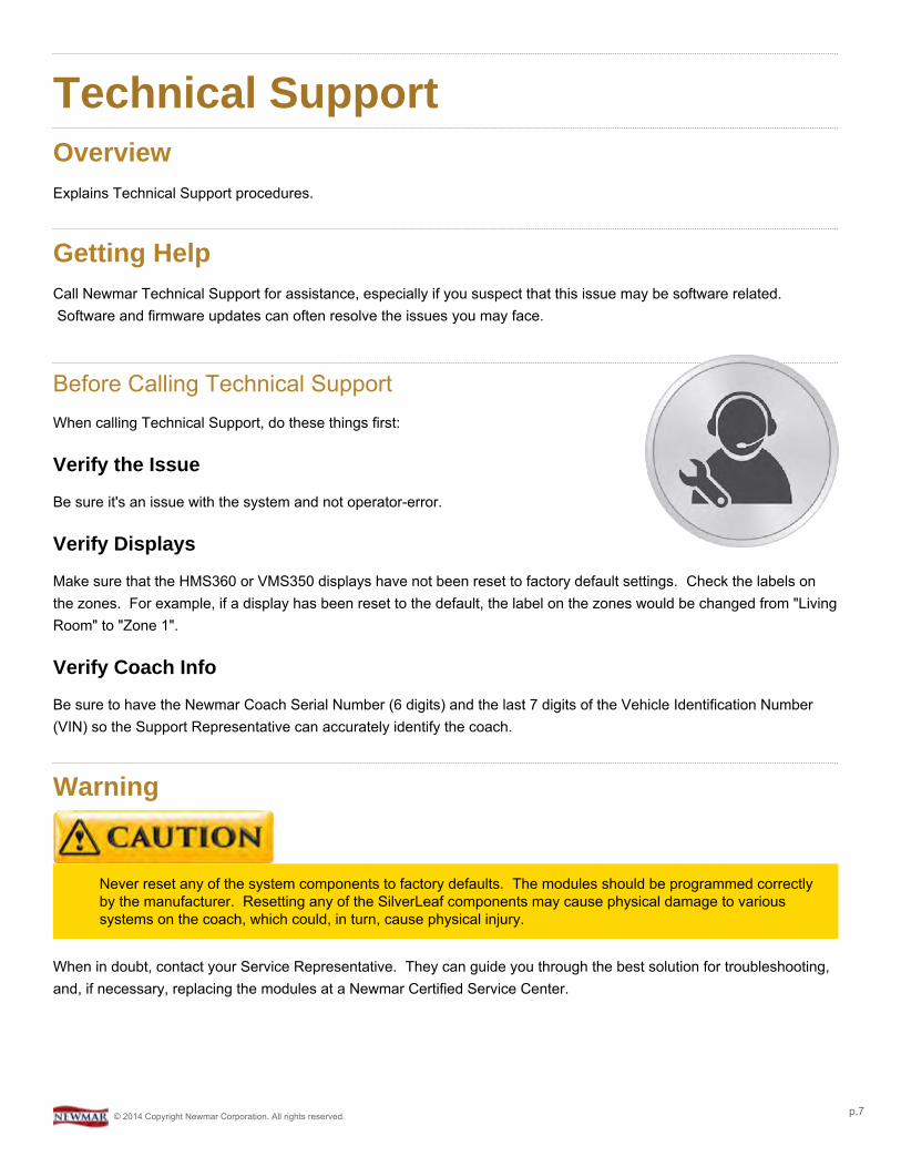
Technical SupportOverviewExplains Technical Support procedures.
Getting HelpCall Newmar Technical Support for assistance, especially if you suspect that this issue may be software related.Software and firmware updates can often resolve the issues you may face.
Before Calling Technical SupportWhen calling Technical Support, do these things first:
Verify the Issue
Be sure it's an issue with the system and not operator-error.
Verify Displays
Make sure that the HMS360 or VMS350 displays have not been reset to factory default settings. Check the labels onthe zones. For example, if a display has been reset to the default, the label on the zones would be changed from "LivingRoom" to "Zone 1".
Verify Coach Info
Be sure to have the Newmar Coach Serial Number (6 digits) and the last 7 digits of the Vehicle Identification Number(VIN) so the Support Representative can accurately identify the coach.
Warning
Never reset any of the system components to factory defaults. The modules should be programmed correctlyby the manufacturer. Resetting any of the SilverLeaf components may cause physical damage to varioussystems on the coach, which could, in turn, cause physical injury.
When in doubt, contact your Service Representative. They can guide you through the best solution for troubleshooting,and, if necessary, replacing the modules at a Newmar Certified Service Center.
© 2014 Copyright Newmar Corporation. All rights reserved. p.7
HomeOverviewAll of the control functions are accessed by pressing one of the buttons on the Home screen.
Home ScreenThe Home screen displays prioritized system status messages and warnings. It also provides access to all of the mainfunctions controlled by SilverLeaf. These functions are accessible by tapping one of the buttons in the left or centercolumn. The descriptions for each of these buttons are below.
Pressing the "Home" button from any of the display screens will return the User to the initial screen.
Coaches without Floor HeatCoaches that are not equipped with optional Floor Heat will see a "Temp" button listed on their Home screen display.
SilverLeaf > Home Screen. As shown on systems without the optional Floor Heat.
Coaches with Floor HeatCoaches equipped with the optional Floor Heat will not have a "Temp" button listed on their Home screen display.Instead, they will see a button labeled "Floor" in its place.
© 2014 Copyright Newmar Corporation. All rights reserved. p.8
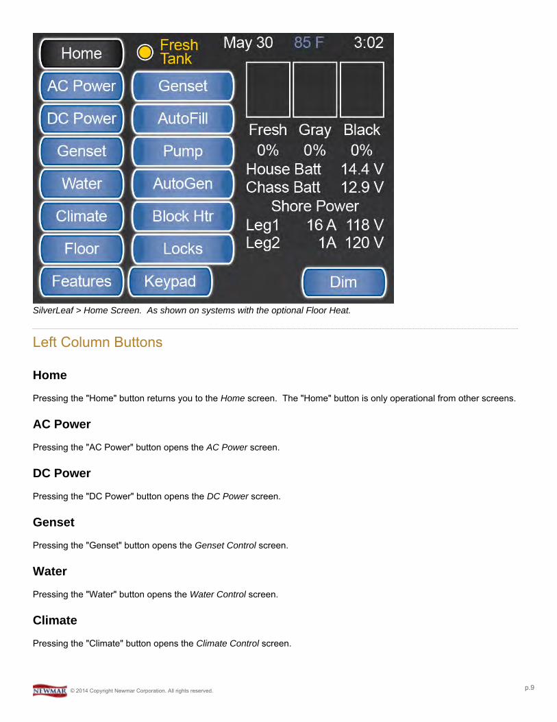
SilverLeaf > Home Screen. As shown on systems with the optional Floor Heat.
Left Column Buttons
Home
Pressing the "Home" button returns you to the Home screen. The "Home" button is only operational from other screens.
AC Power
Pressing the "AC Power" button opens the AC Power screen.
DC Power
Pressing the "DC Power" button opens the DC Power screen.
Genset
Pressing the "Genset" button opens the Genset Control screen.
Water
Pressing the "Water" button opens the Water Control screen.
Climate
Pressing the "Climate" button opens the Climate Control screen.
© 2014 Copyright Newmar Corporation. All rights reserved. p.9
Temp
Pressing the "Temp" button opens the Temperature screen to display the outside ambient temperature. This button isonly available if the coach is not equipped with Floor Heat.
Floor
Pressing the "Floor" button opens the Floor Heat Control screen. This button is only available if the coach is equippedwith Floor Heat.
Features
Pressing the "Features" button opens the Features/Configurations screen, which provides access to numerousfunctional controls. These functions will be further explained in future sections.
Center Column Buttons
Genset
Pressing the "Genset" button in the center column will manually START and STOP the generator. The button indicatoris highlighted when the generator is running. This button works the same as the Dash and other remote generatorswitches.
AutoFill
Pressing the "AutoFill" button will turn the Fresh Water Tank AutoFill feature ON or OFF. The button indicator ishighlighted when the AutoFill feature is ON.
Pump
Pressing the "Pump" button will turn the Fresh Water Pump ON or OFF. The button indicator is highlighted when thepump is powered ON.
AutoGen
Pressing the "AutoGen" button will select the AGS (Auto Generator Start) Control screen. The button indicator ishighlighted when the AutoGen feature is enabled.
Block Htr
Pressing the "Block Htr" button toggles the Block Heater relay ON or OFF. The button indicator is highlighted yellowwhen the load is being shed, or shut down due to lack of available power, and blue when ON.
Locks
The "Locks" button allows you to lock the entry door and the cargo doors on the SilverLeaf display.
© 2014 Copyright Newmar Corporation. All rights reserved. p.10

Keypad
The "Keypad" button will take you to the Shade and Light Control screen, which is found under Features > VirtualKeypad, where you can control the ceiling lights and the "All Shade" function
Status Displays
Overall System Status
The Overall System Status area is located just above the middle column of buttons on the Home screen. This area willsay "OK" if no errors or warnings are present. Warnings and errors will be displayed in this area in order of priority. Forexample, in the sample screenshots provided above, the Overall System Status area contains "AC" and "Fresh Tank"warnings.
Date | Outside Temp | Time
The system date, outside temperature, and time are displayed across the top-right side of the screen.
Tank Status
The fresh, gray, and black holding tanks status is displayed as a percentage of full. These values are displayed as botha numerical percentage and bar graph representation.
DC Voltage
The "House Batt" and "Chassis Batt" voltage values are displayed beneath the Tank Status.
Charge Bridge Indicator
The Charge Bridge function ties the two battery banks, House and Chassis, together. The Charge Bridge Indicator is ayellow lightning bolt that appears between the DC Voltage values when the Charge Bridge is energized.
AC Power Values
The AC Power Source (Shore, Generator, Inverter), Voltage, and Current (Amperage) for both AC power legs aredisplayed.
Dim Button
This button controls the brightness of the screen.
© 2014 Copyright Newmar Corporation. All rights reserved. p.11
AC PowerOverviewDisplays the AC Power Source, Line Voltage, Amp Usage, and AC Line Frequency.
AC Power ScreenThe AC Power screen displays the Alternating Current (AC) Power Source, Line Voltage, Current (or Amperage) Usage,and AC Line Frequency (Hz).
SilverLeaf > AC Power screen
Power Source
The AC Power Source is displayed for Shore Power, Generator or Inverter Power.
Line Frequency
The AC Line Frequency is displayed in Hertz (Hz).
Amperage
AC Amperage values are displayed in a bar graph and numerically for each leg.
© 2014 Copyright Newmar Corporation. All rights reserved. p.12

Max Charger Draw Amps
The AC Power screen also displays the Maximum Charger Draw Amps setting value.
Inverter Status
Inverter status is displayed on this screen. The user can turn an inverter ON or OFF using the "Change" buttons on thisscreen. Please note that the option for a second inverter is only available in the King Aire.
© 2014 Copyright Newmar Corporation. All rights reserved. p.13
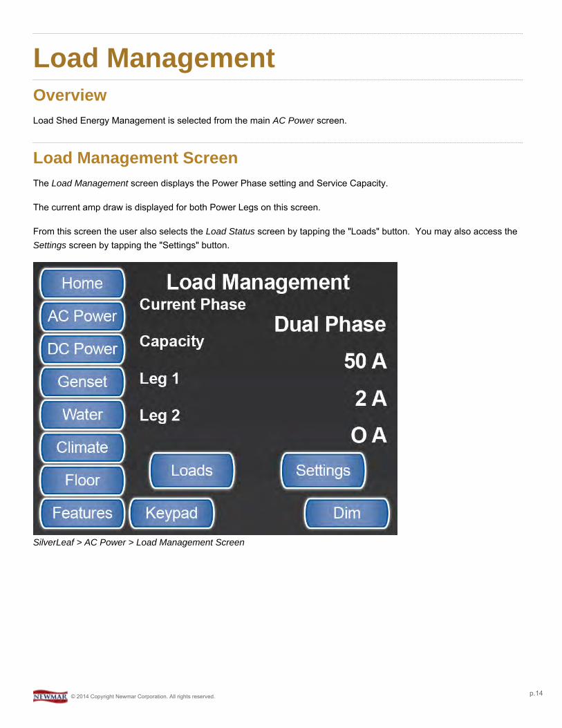
Load ManagementOverviewLoad Shed Energy Management is selected from the main AC Power screen.
Load Management ScreenThe Load Management screen displays the Power Phase setting and Service Capacity.
The current amp draw is displayed for both Power Legs on this screen.
From this screen the user also selects the Load Status screen by tapping the "Loads" button. You may also access theSettings screen by tapping the "Settings" button.
SilverLeaf > AC Power > Load Management Screen
© 2014 Copyright Newmar Corporation. All rights reserved. p.14
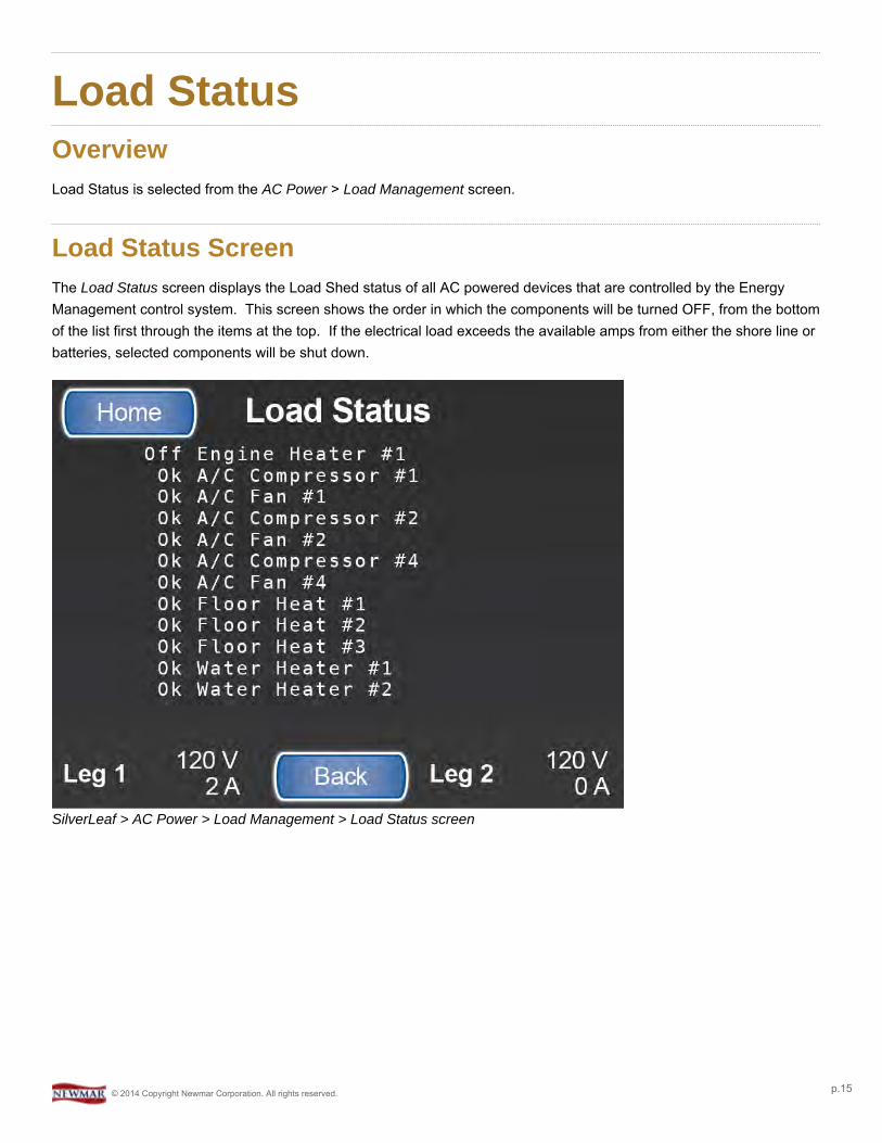
Load StatusOverviewLoad Status is selected from the AC Power > Load Management screen.
Load Status ScreenThe Load Status screen displays the Load Shed status of all AC powered devices that are controlled by the EnergyManagement control system. This screen shows the order in which the components will be turned OFF, from the bottomof the list first through the items at the top. If the electrical load exceeds the available amps from either the shore line orbatteries, selected components will be shut down.
SilverLeaf > AC Power > Load Management > Load Status screen
© 2014 Copyright Newmar Corporation. All rights reserved. p.15
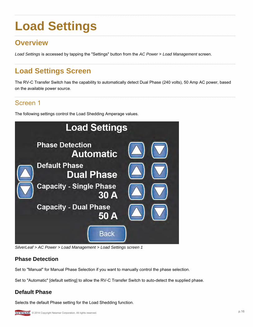
Load SettingsOverviewLoad Settings is accessed by tapping the "Settings" button from the AC Power > Load Management screen.
Load Settings ScreenThe RV-C Transfer Switch has the capability to automatically detect Dual Phase (240 volts), 50 Amp AC power, basedon the available power source.
Screen 1The following settings control the Load Shedding Amperage values.
SilverLeaf > AC Power > Load Management > Load Settings screen 1
Phase Detection
Set to "Manual" for Manual Phase Selection if you want to manually control the phase selection.
Set to "Automatic" [default setting] to allow the RV-C Transfer Switch to auto-detect the supplied phase.
Default Phase
Selects the default Phase setting for the Load Shedding function.
© 2014 Copyright Newmar Corporation. All rights reserved. p.16

Capacity-Single Phase
This sets the Load Shedding Amperage value for the Single Phase selection.
Newmar recommends for "Capacity - Single Phase" function be set to '30 Amps' or less.
Capacity-Dual Phase
This sets the Load Shedding Amperage value for the Dual Phase selection.
Screen 2Use the second screen to manage the Electrical Capacity, Load Shedding, Generator and Charger options.
SilverLeaf > AC Power > Load Management > Load Settings screen 2
Capacity-Generator
This setting specifies the maximum available amperage the Generator can output.
Newmar recommends the "Capacity - Generator" ["Genset Capacity"] function be set to '40 Amps' in coachesequipped with a 10,000 watt generator -- Mountain Aire and London Aire.
© 2014 Copyright Newmar Corporation. All rights reserved. p.17
Newmar recommends the "Capacity - Generator" ["Genset Capacity"] function be set to '50 Amps' in coachesequipped with a 12,500 watt generator -- Essex and King Aire.
Load Shedding
Having Load Shedding set to "Enabled" allows the control system to automatically manage the AC power system basedon the Capacity settings from Screen 1. The system will 'shed' (turn OFF) system configured AC power devices in orderto maintain a maximum phase capacity AC amperage usage.
Newmar recommends the "Load Shedding" function be set to 'Enabled'.
Generator Settling
This setting allows the generator to "settle down" and level out before a load is allowed to be put on the system.
Newmar recommends the "Generator Settling" ["Genset Settling"] function be set to 'Enabled' for proper AutoGen operation.
Charger 1 Shedding
This setting determines if Battery Charger #1 should be 'shed' (turned OFF) with the other Load Shedding devices.
Newmar recommends the "Charger 1 Shedding" function be set to 'Disabled'.
Screen 3Use the third screen to manage the Load Shedding, Generator and Charger options.
© 2014 Copyright Newmar Corporation. All rights reserved. p.18
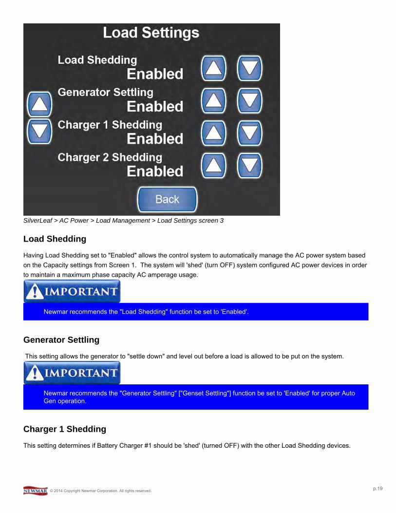
SilverLeaf > AC Power > Load Management > Load Settings screen 3
Load Shedding
Having Load Shedding set to "Enabled" allows the control system to automatically manage the AC power system basedon the Capacity settings from Screen 1. The system will 'shed' (turn OFF) system configured AC power devices in orderto maintain a maximum phase capacity AC amperage usage.
Newmar recommends the "Load Shedding" function be set to 'Enabled'.
Generator Settling
This setting allows the generator to "settle down" and level out before a load is allowed to be put on the system.
Newmar recommends the "Generator Settling" ["Genset Settling"] function be set to 'Enabled' for proper AutoGen operation.
Charger 1 Shedding
This setting determines if Battery Charger #1 should be 'shed' (turned OFF) with the other Load Shedding devices.
© 2014 Copyright Newmar Corporation. All rights reserved. p.19

Newmar recommends the "Charger 1 Shedding" function be set to 'Disabled'.
Charger 2 Shedding
If the coach is equipped, this setting determines if Battery Charger #2 should be 'shed' (turned OFF) with the other LoadShedding devices.
Newmar recommends the "Charger 2 Shedding" function be set to 'Enabled'.
© 2014 Copyright Newmar Corporation. All rights reserved. p.20

DC PowerOverviewDisplays the status of the DC Inverters and allows the access to the Inverter Settings screens.
DC Power ScreenThe DC Power screen displays the status of the Inverters or Chargers and the Direct Current or DC. This screen alsoallows the user to access the Operator Accessible Inverter/Charger Settings screens.
SilverLeaf > DC Power screen
The King Aire is the only Newmar coach with 2 inverters/chargers. A blank space will be displayed where thereis only one inverter, as in Mountain Aire, London Aire, and Essex models, and there will not be a status orSettings button for Charger 2.
BatteryA Battery icon displays a vertical bar graph to indicate the battery charge level along with the battery voltage values.
© 2014 Copyright Newmar Corporation. All rights reserved. p.21

DC CurrentThe arrows between the Battery and Inverter icon(s) indicate the direction of the DC current flow. The DC current oramperage value is also displayed.
DiscThe "Disc" button is used to disconnect the 12v power of the house batteries from all 12v components in the coach.This can be used when the coach is going to be stored for a period of time.
© 2014 Copyright Newmar Corporation. All rights reserved. p.22
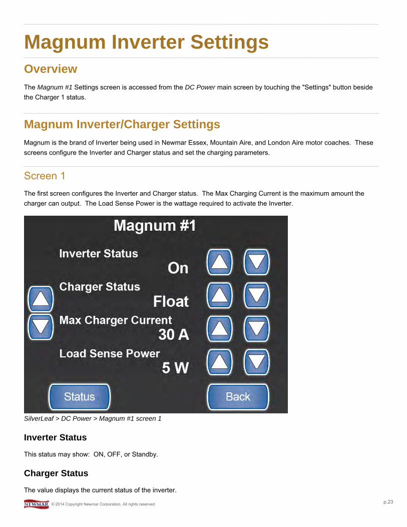
Magnum Inverter SettingsOverviewThe Magnum #1 Settings screen is accessed from the DC Power main screen by touching the "Settings" button besidethe Charger 1 status.
Magnum Inverter/Charger SettingsMagnum is the brand of Inverter being used in Newmar Essex, Mountain Aire, and London Aire motor coaches. Thesescreens configure the Inverter and Charger status and set the charging parameters.
Screen 1The first screen configures the Inverter and Charger status. The Max Charging Current is the maximum amount thecharger can output. The Load Sense Power is the wattage required to activate the Inverter.
SilverLeaf > DC Power > Magnum #1 screen 1
Inverter Status
This status may show: ON, OFF, or Standby.
Charger Status
The value displays the current status of the inverter.
© 2014 Copyright Newmar Corporation. All rights reserved. p.23
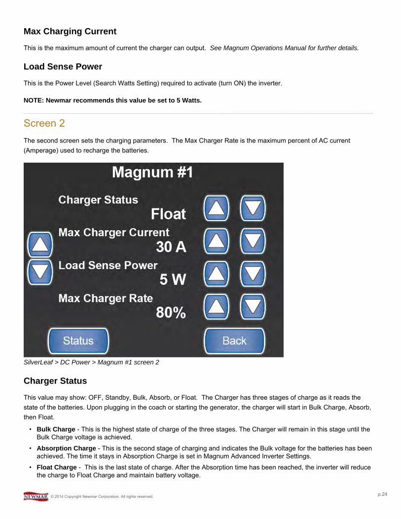
Max Charging Current
This is the maximum amount of current the charger can output. See Magnum Operations Manual for further details.
Load Sense Power
This is the Power Level (Search Watts Setting) required to activate (turn ON) the inverter.
NOTE: Newmar recommends this value be set to 5 Watts.
Screen 2The second screen sets the charging parameters. The Max Charger Rate is the maximum percent of AC current(Amperage) used to recharge the batteries.
SilverLeaf > DC Power > Magnum #1 screen 2
Charger Status
This value may show: OFF, Standby, Bulk, Absorb, or Float. The Charger has three stages of charge as it reads thestate of the batteries. Upon plugging in the coach or starting the generator, the charger will start in Bulk Charge, Absorb,then Float.
• Bulk Charge - This is the highest state of charge of the three stages. The Charger will remain in this stage until theBulk Charge voltage is achieved.
• Absorption Charge - This is the second stage of charging and indicates the Bulk voltage for the batteries has beenachieved. The time it stays in Absorption Charge is set in Magnum Advanced Inverter Settings.
• Float Charge - This is the last state of charge. After the Absorption time has been reached, the inverter will reducethe charge to Float Charge and maintain battery voltage.
© 2014 Copyright Newmar Corporation. All rights reserved. p.24

Max Charging Current
This is the maximum amount of current the charger can output. See Magnum or Xantrex Operations Manual for furtherdetails.
Load Sense Power
This is the Power Level (Search Watts Setting) required to activate (turn ON) the inverter.
Max Charger Rate
This is the maximum percentage of AC current (amperage) used to recharge the batteries.
© 2014 Copyright Newmar Corporation. All rights reserved. p.25
Magnum Inverter StatusOverviewMagnum #1 Status is selected from the Magnum #1 Settings screen.
Magnum Inverter Status ScreenIn addition to showing the status of the Inverter, the Magnum #1 Status screen is where you go to equalize the batteries.This screen also provides access to the Advanced screens.
SilverLeaf > DC Power > Magnum #1 Settings > Magnum #1 Status screen
Magnum Model/VersionThis value is read from the Inverter Module.
Battery TemperatureThis value is read from the inverter battery temperature sensor via the Inverter Module.
Internal TemperatureThis value is read from the inverter via the Inverter Module and shows the current temperature inside the Inverter.
© 2014 Copyright Newmar Corporation. All rights reserved. p.26
FET TemperatureThis value is read from the inverter via the Inverter Module and shows the current temperature of the Field EffectTransistor board inside the Inverter.
Equalize ButtonThis function will take you to a screen to allow you to Equalize your batteries. Equalizing is an overcharge performed onFLOODED LEAD ACID BATTERIES after they have been fully charged. It reverses the buildup of negative chemicaleffects like stratification, a condition where acid concentration is greater at the bottom of the battery than at the top.Equalizing also helps to remove sulfate crystals that may build up on the plates. If left unchecked, a condition calledsulfation will reduce the overall capacity of the battery.
Newmar recommends that the "EQUALIZE" function be performed at a Newmar Certified Service Center.
You should never equalize AGM batteries. This will cause damage to AGM batteries.
Advanced Button
This screen is password protected to allow Qualified Service Technicians access to make changes to thecontrol settings. Changing these control settings to improper values can adversely affect the operation of thecontrol system and may cause damage to the coach.
© 2014 Copyright Newmar Corporation. All rights reserved. p.27
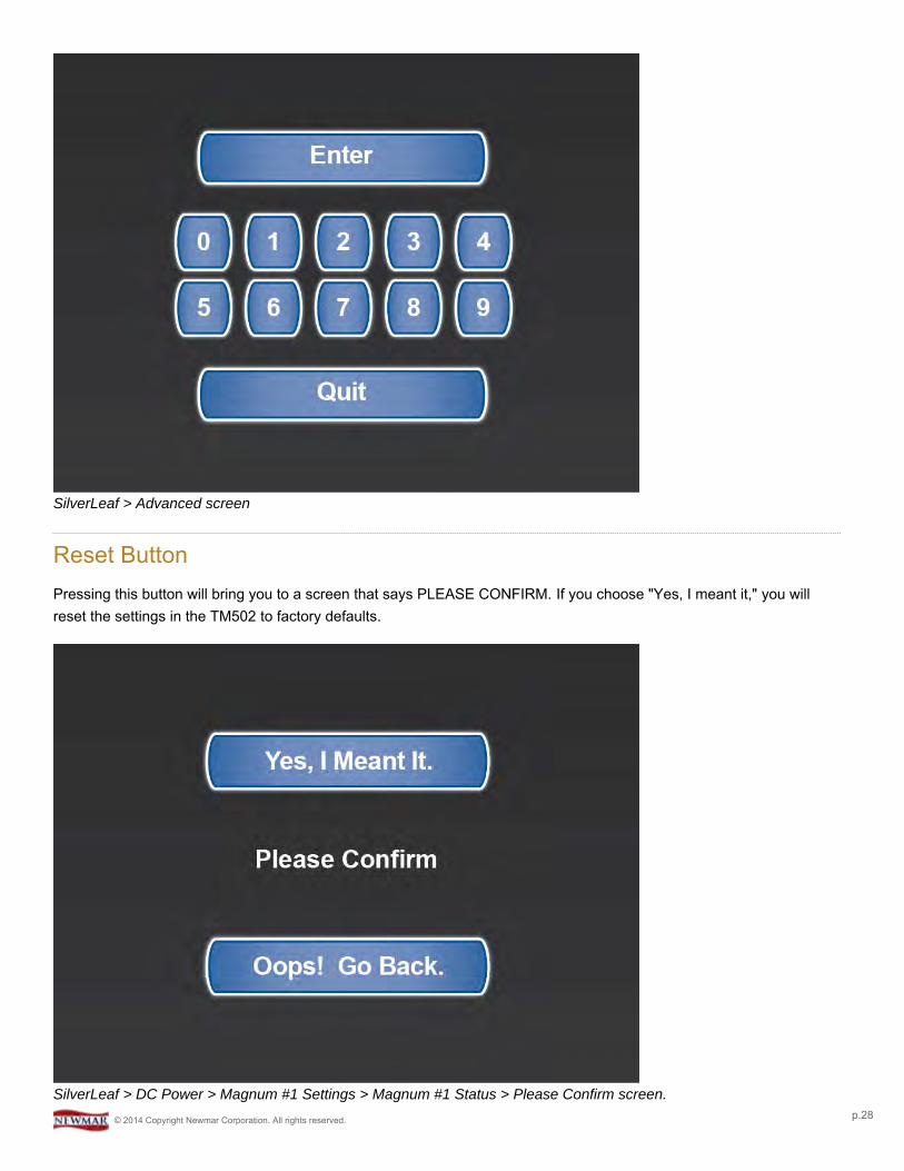
SilverLeaf > Advanced screen
Reset ButtonPressing this button will bring you to a screen that says PLEASE CONFIRM. If you choose "Yes, I meant it," you willreset the settings in the TM502 to factory defaults.
SilverLeaf > DC Power > Magnum #1 Settings > Magnum #1 Status > Please Confirm screen.© 2014 Copyright Newmar Corporation. All rights reserved. p.28

Never reset any of the system components to factory defaults. The modules should be programmed correctlyby the manufacturer. Resetting any of the SilverLeaf components may cause physical damage to varioussystems on the coach, which could, in turn, cause physical injury.
When in doubt, contact your Service Representative. They can guide you through the best solution for troubleshooting,and, if necessary, replacing the modules at a Newmar Certified Service Center.
Back ButtonThis will take the user back to the DC POWER main screen.
© 2014 Copyright Newmar Corporation. All rights reserved. p.29
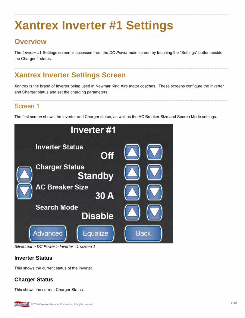
Xantrex Inverter #1 SettingsOverviewThe Inverter #1 Settings screen is accessed from the DC Power main screen by touching the "Settings" button besidethe Charger 1 status.
Xantrex Inverter Settings ScreenXantrex is the brand of Inverter being used in Newmar King Aire motor coaches. These screens configure the Inverterand Charger status and set the charging parameters.
Screen 1The first screen shows the Inverter and Charger status, as well as the AC Breaker Size and Search Mode settings.
SilverLeaf > DC Power > Inverter #1 screen 1
Inverter Status
This shows the current status of the inverter.
Charger Status
This shows the current Charger Status.
© 2014 Copyright Newmar Corporation. All rights reserved. p.30
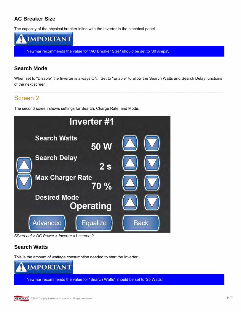
AC Breaker Size
The capacity of the physical breaker inline with the Inverter in the electrical panel.
Newmar recommends the value for "AC Breaker Size" should be set to '30 Amps'.
Search Mode
When set to "Disable" the Inverter is always ON. Set to "Enable" to allow the Search Watts and Search Delay functionsof the next screen.
Screen 2The second screen shows settings for Search, Charge Rate, and Mode.
SilverLeaf > DC Power > Inverter #1 screen 2
Search Watts
This is the amount of wattage consumption needed to start the Inverter.
Newmar recommends the value for "Search Watts" should be set to '25 Watts'.
© 2014 Copyright Newmar Corporation. All rights reserved. p.31
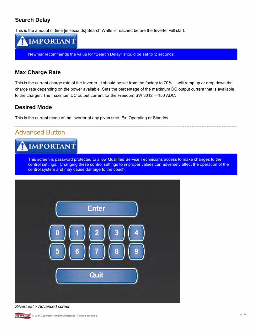
Search Delay
This is the amount of time [in seconds] Search Watts is reached before the Inverter will start.
Newmar recommends the value for "Search Delay" should be set to '2 seconds'.
Max Charge Rate
This is the current charge rate of the Inverter. It should be set from the factory to 70%. It will ramp up or drop down thecharge rate depending on the power available. Sets the percentage of the maximum DC output current that is availableto the charger. The maximum DC output current for the Freedom SW 3012 —150 ADC.
Desired Mode
This is the current mode of the inverter at any given time. Ex: Operating or Standby
Advanced Button
This screen is password protected to allow Qualified Service Technicians access to make changes to thecontrol settings. Changing these control settings to improper values can adversely affect the operation of thecontrol system and may cause damage to the coach.
SilverLeaf > Advanced screen
© 2014 Copyright Newmar Corporation. All rights reserved. p.32
Equalize ButtonTouching this will take you to a screen to allow you to Equalize your batteries.
Newmar recommends that the "EQUALIZE" function be performed at a Newmar Certified Service Center.
YOU SHOULD NEVER EQUALIZE AGM BATTERIES. THIS WILL CAUSE DAMAGE TO AND POSSIBLYRUIN AGM BATTERIES.
Back ButtonThis will take the user back to the DC POWER main screen.
© 2014 Copyright Newmar Corporation. All rights reserved. p.33
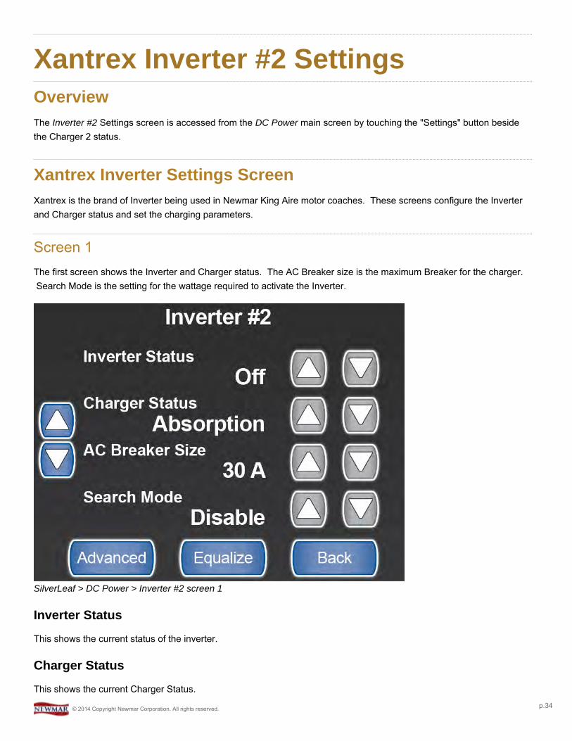
Xantrex Inverter #2 SettingsOverviewThe Inverter #2 Settings screen is accessed from the DC Power main screen by touching the "Settings" button besidethe Charger 2 status.
Xantrex Inverter Settings ScreenXantrex is the brand of Inverter being used in Newmar King Aire motor coaches. These screens configure the Inverterand Charger status and set the charging parameters.
Screen 1The first screen shows the Inverter and Charger status. The AC Breaker size is the maximum Breaker for the charger.Search Mode is the setting for the wattage required to activate the Inverter.
SilverLeaf > DC Power > Inverter #2 screen 1
Inverter Status
This shows the current status of the inverter.
Charger Status
This shows the current Charger Status.
© 2014 Copyright Newmar Corporation. All rights reserved. p.34
AC Breaker Size
The capacity of the physical breaker inline with the Inverter in the electrical panel.
Newmar recommends the value for "AC Breaker Size" should be set to '30 Amps'.
Search Mode
When set to "Disable" the Inverter is always ON. Set to "Enable" to allow the Search Watts and Search Delay functionsof the next screen.
Advanced Button
This screen is password protected to allow Qualified Service Technicians access to make changes to thecontrol settings. Changing these control settings to improper values can adversely affect the operation of thecontrol system and may cause damage to the coach.
SilverLeaf > Advanced screen
Equalize Button
Touching this will take you to a screen to allow you to Equalize your batteries.
© 2014 Copyright Newmar Corporation. All rights reserved. p.35
Newmar recommends that the "EQUALIZE" function be performed at a Newmar Certified Service Center.
YOU SHOULD NEVER EQUALIZE AGM BATTERIES. THIS WILL CAUSE DAMAGE TO AND POSSIBLYRUIN AGM BATTERIES.
Back Button
This will take the user back to the DC POWER main screen.
Screen 2The second screen shows settings for Search, Charge Rate, and Mode.
SilverLeaf > DC Power > Inverter #2 screen 2
Search Watts
This is the amount of wattage consumption needed to start the Inverter.
Newmar recommends the value for "Search Watts" should be set to '25 Watts'.
© 2014 Copyright Newmar Corporation. All rights reserved. p.36

Search Delay
This is the amount of time [in seconds] Search Watts is reached before the Inverter will start.
Newmar recommends the value for "Search Delay" should be set to '2 seconds'.
Max Charge Rate
This is the current charge rate of the Inverter. It should be set from the factory to 70%. It will ramp up or drop down thecharge rate depending on the power available. Sets the percentage of the maximum DC output current that is availableto the charger. The maximum DC output current for the Freedom SW 3012 —150 ADC.
Desired Mode
This is the current mode of the inverter at any given time. Ex: Operating or Standby
Advanced Button
This screen is password protected to allow Qualified Service Technicians access to make changes to thecontrol settings. Changing these control settings to improper values can adversely affect the operation of thecontrol system and may cause damage to the coach.
SilverLeaf > Advanced screen
© 2014 Copyright Newmar Corporation. All rights reserved. p.37
Equalize Button
Touching this will take you to a screen to allow you to Equalize your batteries.
Newmar recommends that the "EQUALIZE" function be performed at a Newmar Certified Service Center.
YOU SHOULD NEVER EQUALIZE AGM BATTERIES. THIS WILL CAUSE DAMAGE TO AND POSSIBLYRUIN AGM BATTERIES.
Back Button
This will take the user back to the DC POWER main screen.
© 2014 Copyright Newmar Corporation. All rights reserved. p.38
Xantrex Inverter #2 AdvancedSettingsOverviewThis page is accessed from the Xantrex Inverter #2 Settings screen. Once authenticated the technician can accessadvanced settings.
Xantrex Inverter #2 Advanced ScreenThis page is part of a protected area of the system and requires a password in to access this information. Onceauthenticated you can access the advanced settings for the Xantrex Inverter #2. Xantrex is the brand of Inverter beingused in Newmar King Aire motor coaches.
Advanced Screen
This screen is password protected to allow Qualified Service Technicians access to make changes to thecontrol settings. Changing these control settings to improper values can adversely affect the operation of thecontrol system and may cause damage to the coach.
SilverLeaf > Advanced screen
© 2014 Copyright Newmar Corporation. All rights reserved. p.39
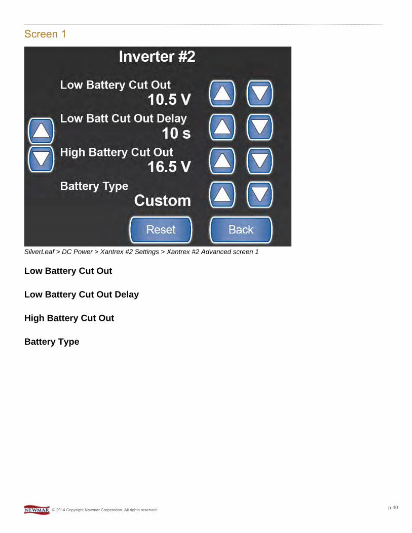
Screen 1
SilverLeaf > DC Power > Xantrex #2 Settings > Xantrex #2 Advanced screen 1
Low Battery Cut Out
Low Battery Cut Out Delay
High Battery Cut Out
Battery Type
© 2014 Copyright Newmar Corporation. All rights reserved. p.40
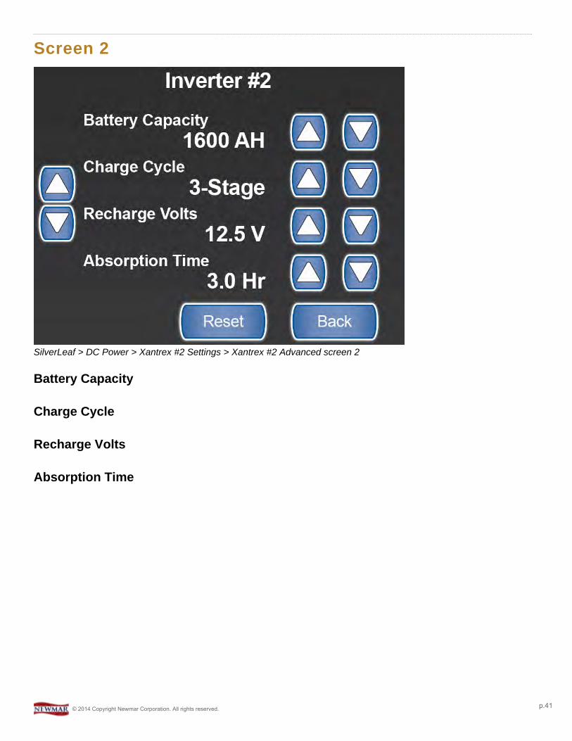
Screen 2
SilverLeaf > DC Power > Xantrex #2 Settings > Xantrex #2 Advanced screen 2
Battery Capacity
Charge Cycle
Recharge Volts
Absorption Time
© 2014 Copyright Newmar Corporation. All rights reserved. p.41
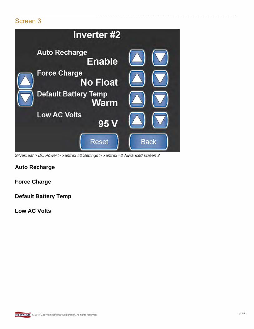
Screen 3
SilverLeaf > DC Power > Xantrex #2 Settings > Xantrex #2 Advanced screen 3
Auto Recharge
Force Charge
Default Battery Temp
Low AC Volts
© 2014 Copyright Newmar Corporation. All rights reserved. p.42
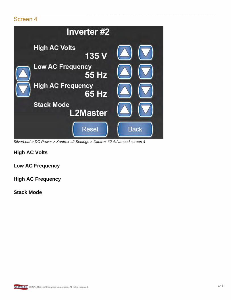
Screen 4
SilverLeaf > DC Power > Xantrex #2 Settings > Xantrex #2 Advanced screen 4
High AC Volts
Low AC Frequency
High AC Frequency
Stack Mode
© 2014 Copyright Newmar Corporation. All rights reserved. p.43

Screen 5
SilverLeaf > DC Power > Xantrex #2 Settings > Xantrex #2 Advanced screen 5
Low AC Frequency
See section from Screen 4 above.
High AC Frequency
See section from Screen 4 above.
Stack Mode
See section from Screen 4 above.
Device Number
© 2014 Copyright Newmar Corporation. All rights reserved. p.44
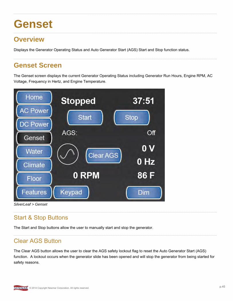
GensetOverviewDisplays the Generator Operating Status and Auto Generator Start (AGS) Start and Stop function status.
Genset ScreenThe Genset screen displays the current Generator Operating Status including Generator Run Hours, Engine RPM, ACVoltage, Frequency in Hertz, and Engine Temperature.
SilverLeaf > Genset
Start & Stop ButtonsThe Start and Stop buttons allow the user to manually start and stop the generator.
Clear AGS ButtonThe Clear AGS button allows the user to clear the AGS safety lockout flag to reset the Auto Generator Start (AGS)function. A lockout occurs when the generator slide has been opened and will stop the generator from being started forsafety reasons.
© 2014 Copyright Newmar Corporation. All rights reserved. p.45
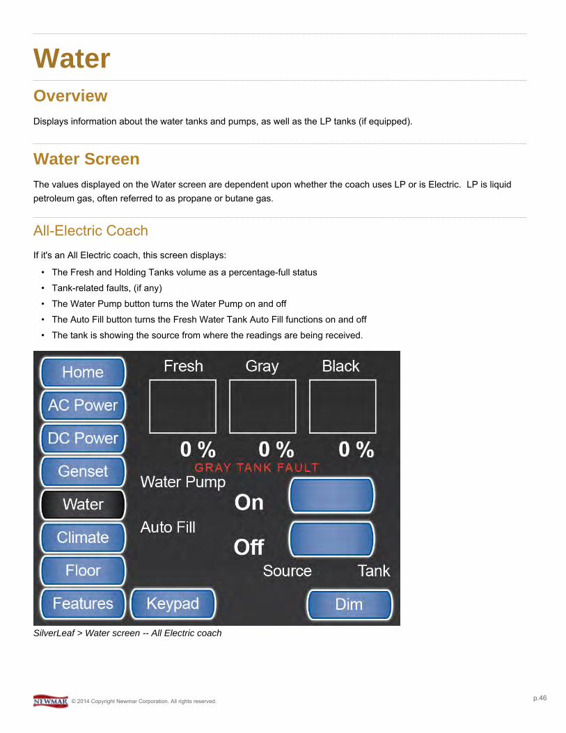
WaterOverviewDisplays information about the water tanks and pumps, as well as the LP tanks (if equipped).
Water ScreenThe values displayed on the Water screen are dependent upon whether the coach uses LP or is Electric. LP is liquidpetroleum gas, often referred to as propane or butane gas.
All-Electric CoachIf it's an All Electric coach, this screen displays:
• The Fresh and Holding Tanks volume as a percentage-full status• Tank-related faults, (if any)• The Water Pump button turns the Water Pump on and off• The Auto Fill button turns the Fresh Water Tank Auto Fill functions on and off• The tank is showing the source from where the readings are being received.
SilverLeaf > Water screen -- All Electric coach
© 2014 Copyright Newmar Corporation. All rights reserved. p.46
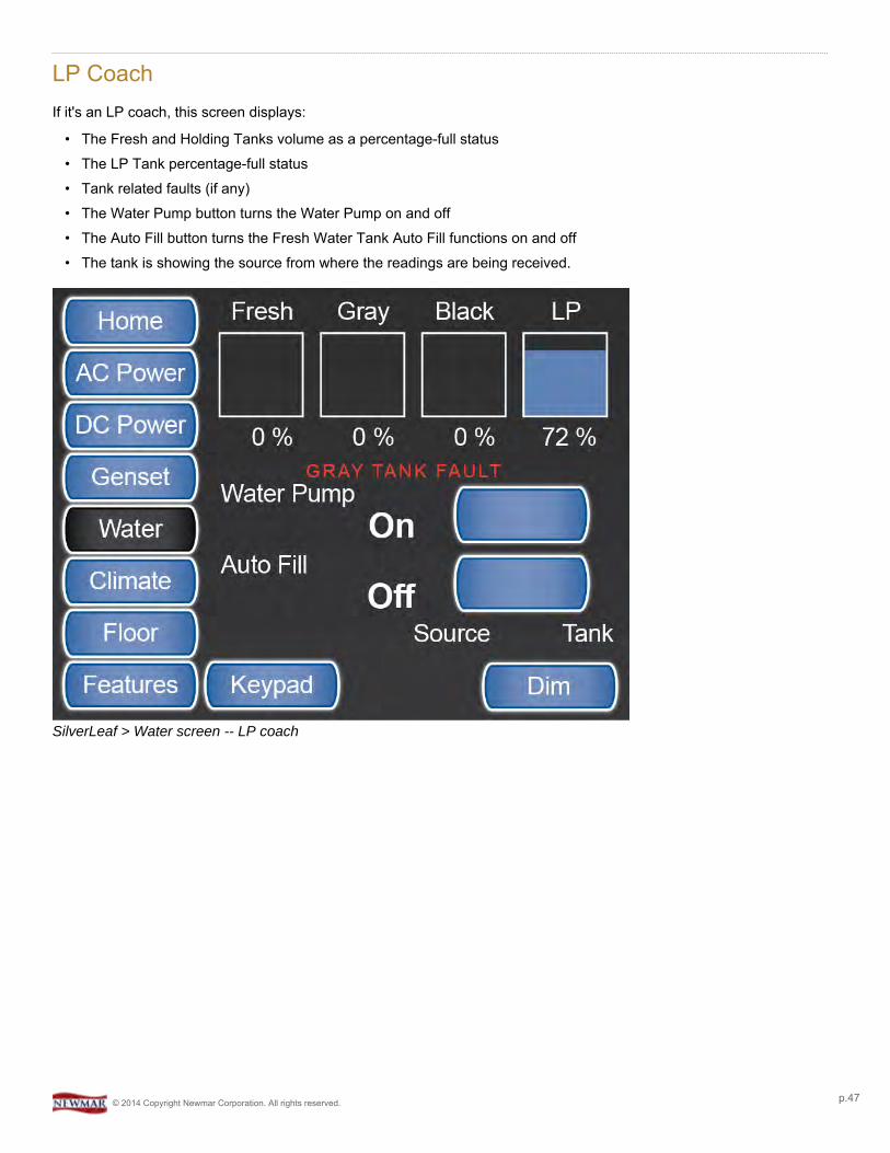
LP CoachIf it's an LP coach, this screen displays:
• The Fresh and Holding Tanks volume as a percentage-full status• The LP Tank percentage-full status• Tank related faults (if any)• The Water Pump button turns the Water Pump on and off• The Auto Fill button turns the Fresh Water Tank Auto Fill functions on and off• The tank is showing the source from where the readings are being received.
SilverLeaf > Water screen -- LP coach
© 2014 Copyright Newmar Corporation. All rights reserved. p.47
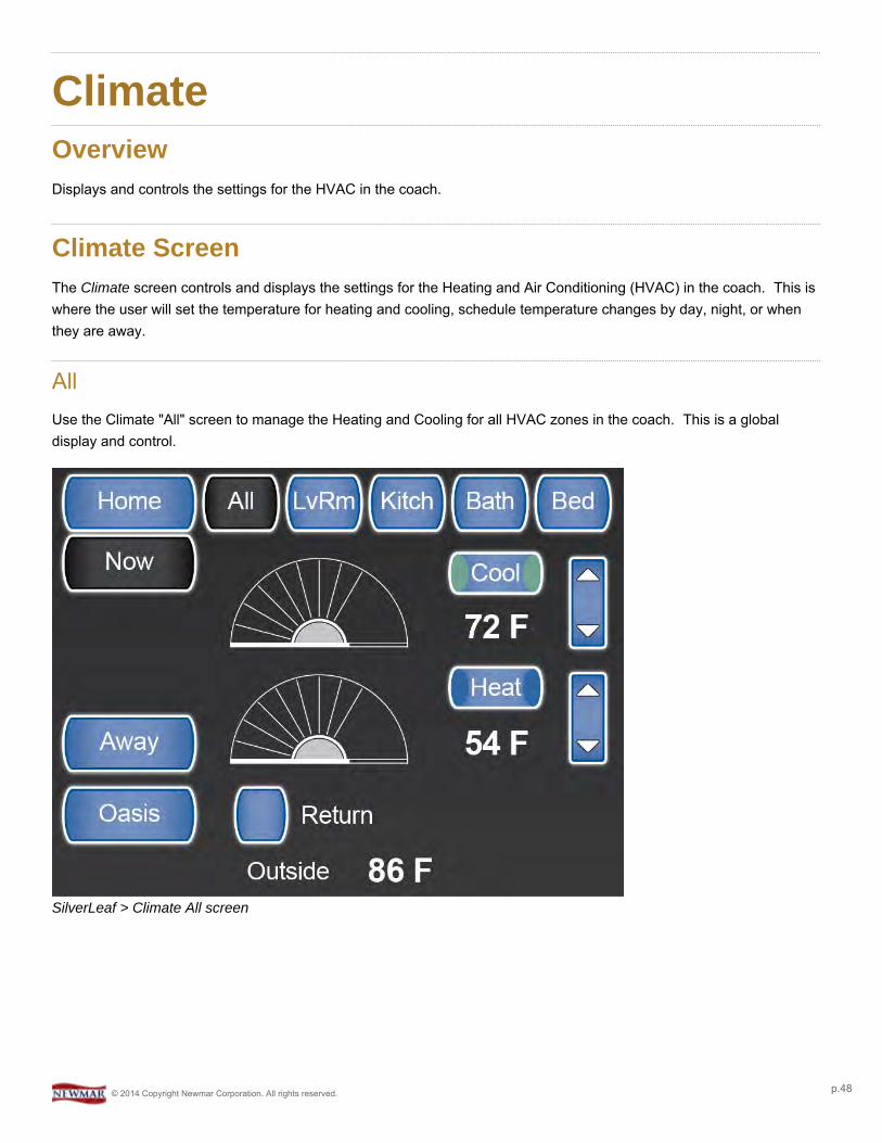
ClimateOverviewDisplays and controls the settings for the HVAC in the coach.
Climate ScreenThe Climate screen controls and displays the settings for the Heating and Air Conditioning (HVAC) in the coach. This iswhere the user will set the temperature for heating and cooling, schedule temperature changes by day, night, or whenthey are away.
AllUse the Climate "All" screen to manage the Heating and Cooling for all HVAC zones in the coach. This is a globaldisplay and control.
SilverLeaf > Climate All screen
© 2014 Copyright Newmar Corporation. All rights reserved. p.48

SilverLeaf > Climate All screen with Scheduled settings
Heat & Cool Buttons
Pressing the Heat or Cool button activates all the zones at one time. The set points are changed by using the up anddown arrows or dragging the "wheel" to the desired temperature.
Schedule
To schedule different temperatures by day, night, or when you are away, click on the appropriate button and set thetemperatures and times as desired.
You can use the "All" button or set the schedule by "Zone". Each Zone can have a different temperature and schedule,but you cannot run the heat in one zone and AC in the other. It is either all AC or all heat.
Leave | Return Button
Near the bottom of the display, above the Outside Temp is a small button labeled either "Leave" or "Return". When youare in the coach the button should be labeled "Leave" and the system should use the temp settings shown on thescreen. When you leave the coach you may press "Leave" to have the system use the temp settings you haveconfigured for "Away" mode. The button label should also change to "Return", which can be changed when you getback to your coach to resume standard Climate control.
There is a small icon in the shape of a door that will appear just beside the "Now" button to indicate when the system isin "Away" mode. This icon may display on all Climate screens when "Away" mode is active.
© 2014 Copyright Newmar Corporation. All rights reserved. p.49
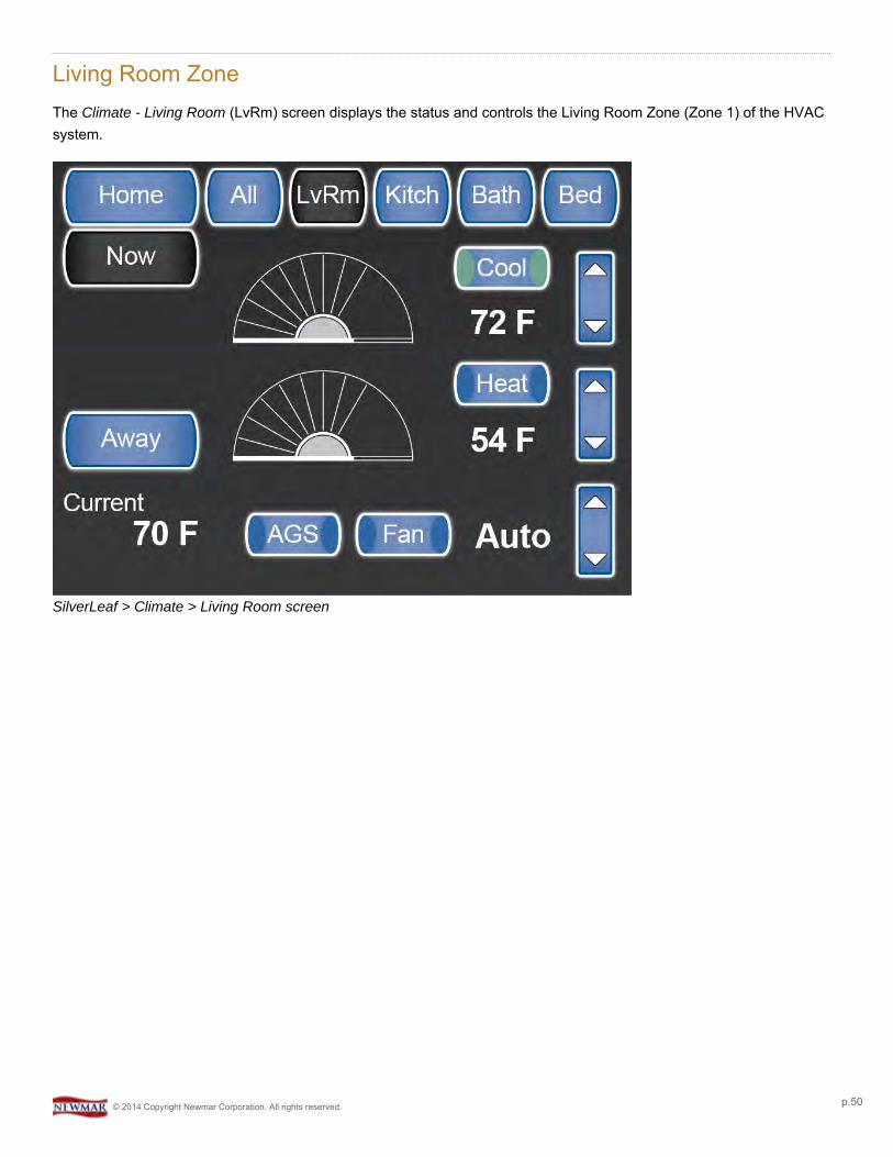
Living Room ZoneThe Climate - Living Room (LvRm) screen displays the status and controls the Living Room Zone (Zone 1) of the HVACsystem.
SilverLeaf > Climate > Living Room screen
© 2014 Copyright Newmar Corporation. All rights reserved. p.50
SilverLeaf > Climate > Living Room screen with Scheduled settings
Heat & Cool Buttons
Pressing the Heat or Cool button activates all the zones at one time. The set points are changed by using the up anddown arrows or dragging the "wheel" to the desired temperature.
Schedule
To schedule different temperatures by day, night, or when you are away, click on the appropriate button and set thetemperatures and times as desired.
You can use the "All" button or set the schedule by "Zone". Each Zone can have a different temperature and schedule,but you cannot run the heat in one zone and cool in the other. It is either all cool or all heat.
AGS Button
The "AGS" button enables the AutoGen Start feature for this zone.
Fan Button
The "Fan" button turns on the fan only for air circulation in this zone.
Kitchen ZoneThe Climate - Kitchen (Kitch) screen displays the status and controls the Kitchen Zone (Zone 2) of the HVAC system.
© 2014 Copyright Newmar Corporation. All rights reserved. p.51

SilverLeaf > Climate > Kitchen screen
SilverLeaf > Climate > Kitchen screen with Scheduled settings
© 2014 Copyright Newmar Corporation. All rights reserved. p.52
Heat & Cool Buttons
Pressing the Heat or Cool button activates all the zones at one time. The set points are changed by using the up anddown arrows or dragging the "wheel" to the desired temperature.
Schedule
To schedule different temperatures by day, night, or when you are away, click on the appropriate button and set thetemperatures and times as desired.
You can use the "All" button or set the schedule by "Zone". Each Zone can have a different temperature and schedule,but you cannot run the heat in one zone and AC in the other. It is either all AC or all heat.
AGS Button
The "AGS" button enables the AutoGen Start feature for this zone.
Fan Button
The "Fan" button turns on the fan for air circulation in this zone.
Bathroom ZoneThe Climate - Bathroom (Bath) screen displays the status and controls the Bathroom Zone (Zone 3) of the HVACsystem.
SilverLeaf > Climate > Bathroom screen
© 2014 Copyright Newmar Corporation. All rights reserved. p.53
SilverLeaf > Climate > Bathroom screen with Scheduled settings
Heat Button
The Climate "Bath" screen only controls the Bathroom Oasis heating system. There is no A/C or Heat Pump availablefor this zone. Pressing the Heat or Cool button activates all the zones at one time. The set points are changed by usingthe up and down arrows or dragging the "wheel" to the desired temperature.
Schedule
To schedule different temperatures by day, night, or when you are away, click on the appropriate button and set thetemperatures and times as desired.
You can use the "All" button or set the schedule by "Zone". Each Zone can have a different temperature and schedule,but you cannot run the heat in one zone and AC in the other. It is either all AC or all heat.
Bedroom ZoneThe Climate - Bedroom (Bed) screen displays the status and controls the Bedroom Zone (Zone 4) of the HVAC system.
© 2014 Copyright Newmar Corporation. All rights reserved. p.54
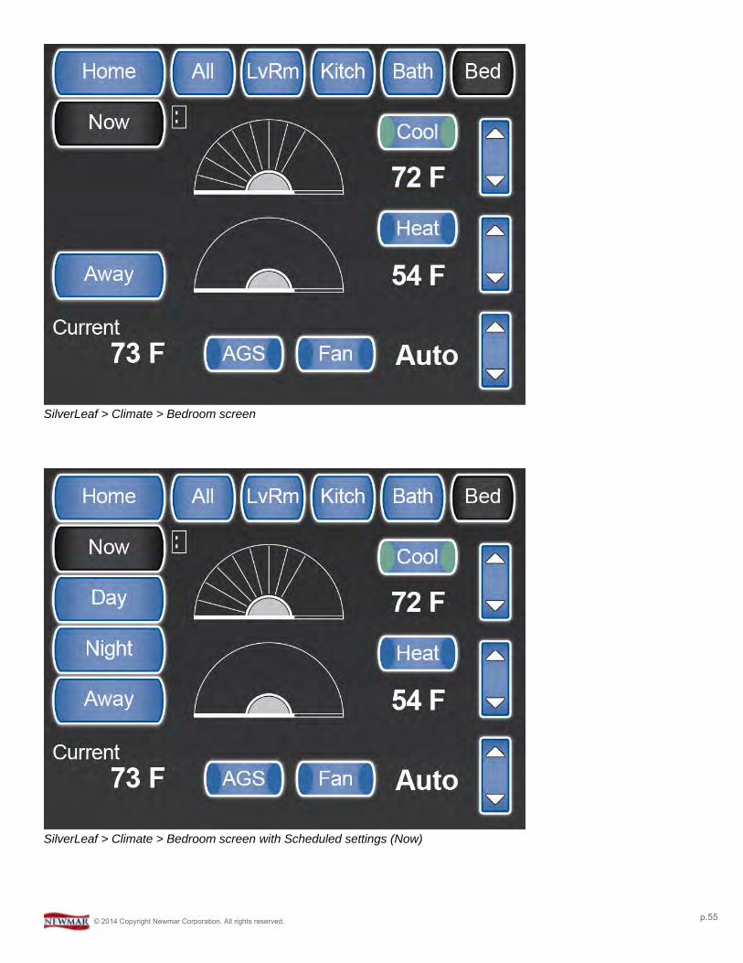
SilverLeaf > Climate > Bedroom screen
SilverLeaf > Climate > Bedroom screen with Scheduled settings (Now)
© 2014 Copyright Newmar Corporation. All rights reserved. p.55
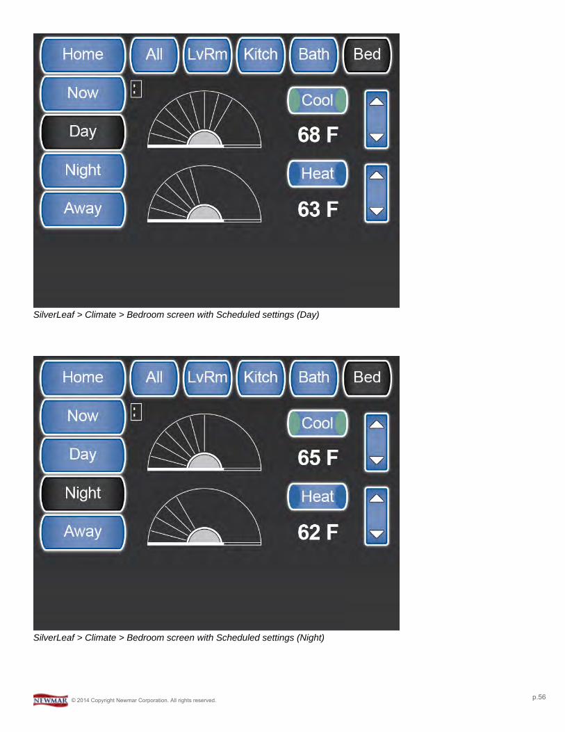
SilverLeaf > Climate > Bedroom screen with Scheduled settings (Day)
SilverLeaf > Climate > Bedroom screen with Scheduled settings (Night)
© 2014 Copyright Newmar Corporation. All rights reserved. p.56
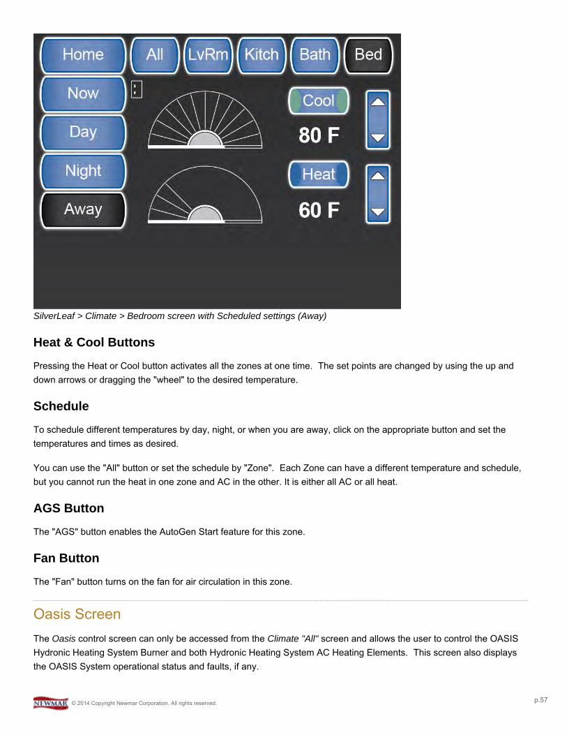
SilverLeaf > Climate > Bedroom screen with Scheduled settings (Away)
Heat & Cool Buttons
Pressing the Heat or Cool button activates all the zones at one time. The set points are changed by using the up anddown arrows or dragging the "wheel" to the desired temperature.
Schedule
To schedule different temperatures by day, night, or when you are away, click on the appropriate button and set thetemperatures and times as desired.
You can use the "All" button or set the schedule by "Zone". Each Zone can have a different temperature and schedule,but you cannot run the heat in one zone and AC in the other. It is either all AC or all heat.
AGS Button
The "AGS" button enables the AutoGen Start feature for this zone.
Fan Button
The "Fan" button turns on the fan for air circulation in this zone.
Oasis ScreenThe Oasis control screen can only be accessed from the Climate "All" screen and allows the user to control the OASISHydronic Heating System Burner and both Hydronic Heating System AC Heating Elements. This screen also displaysthe OASIS System operational status and faults, if any.
© 2014 Copyright Newmar Corporation. All rights reserved. p.57
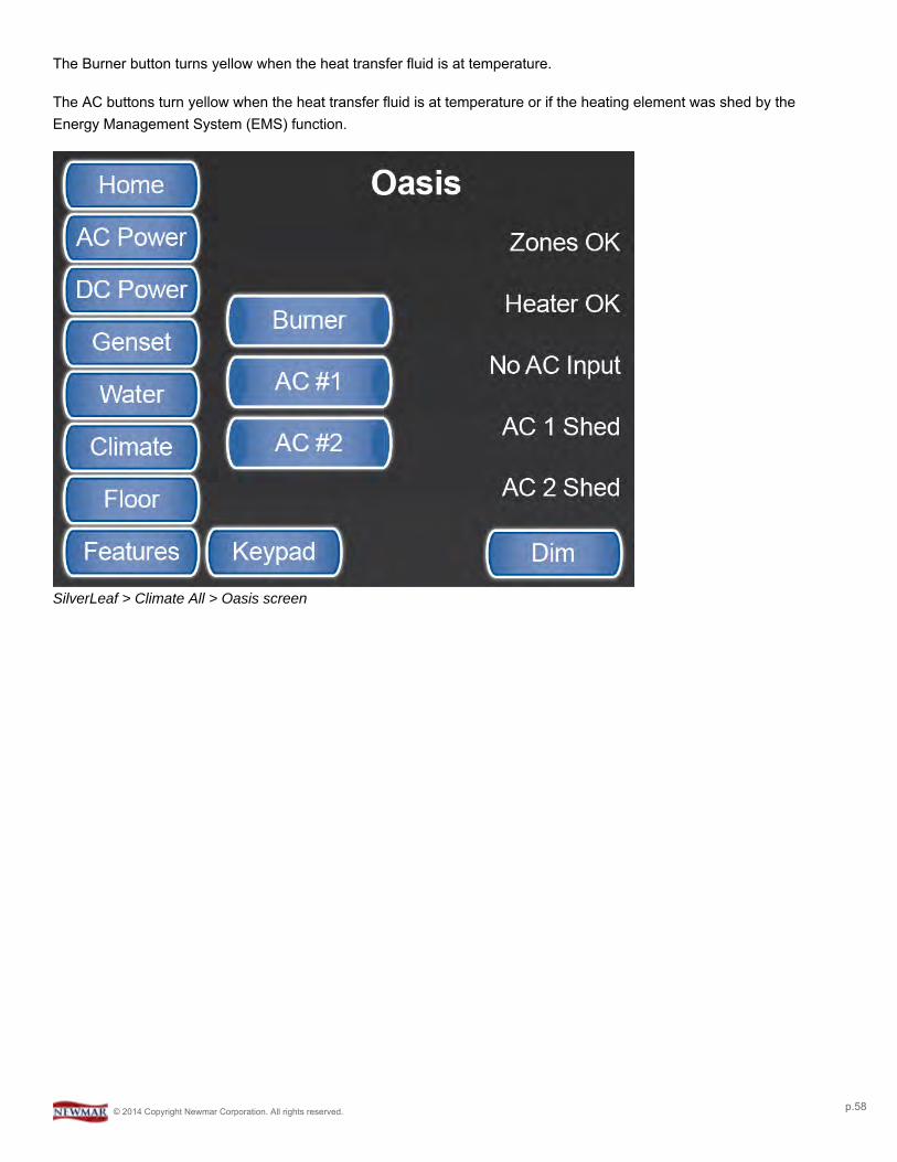
The Burner button turns yellow when the heat transfer fluid is at temperature.
The AC buttons turn yellow when the heat transfer fluid is at temperature or if the heating element was shed by theEnergy Management System (EMS) function.
SilverLeaf > Climate All > Oasis screen
© 2014 Copyright Newmar Corporation. All rights reserved. p.58
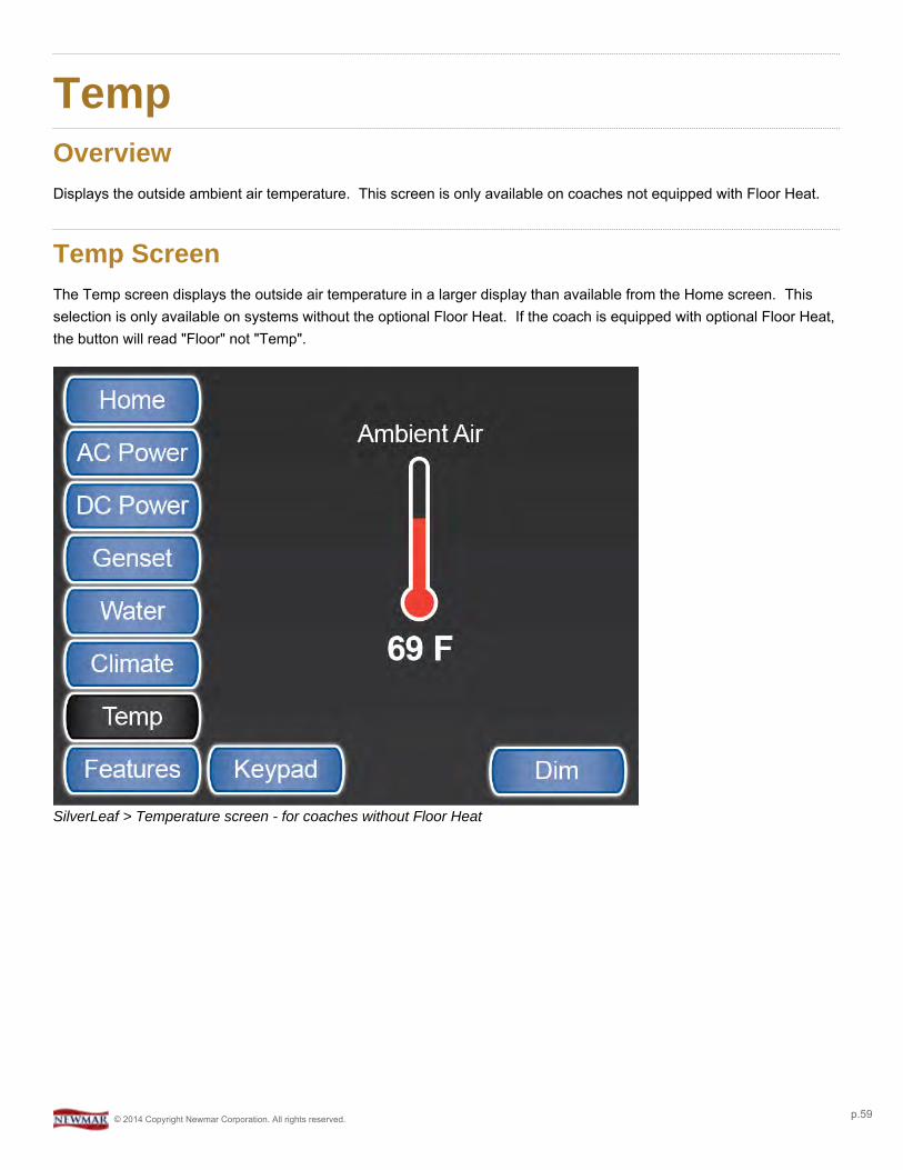
TempOverviewDisplays the outside ambient air temperature. This screen is only available on coaches not equipped with Floor Heat.
Temp ScreenThe Temp screen displays the outside air temperature in a larger display than available from the Home screen. Thisselection is only available on systems without the optional Floor Heat. If the coach is equipped with optional Floor Heat,the button will read "Floor" not "Temp".
SilverLeaf > Temperature screen - for coaches without Floor Heat
© 2014 Copyright Newmar Corporation. All rights reserved. p.59

Floor HeatOverviewDisplays and controls the settings and schedules for Floor Heat.
Floor Heat ScreenThe Floor Heat Control System operates by switching the different floor zone heat mats ON and OFF as determined bythe intervals and values selected.
Screen 1The Floor Heat zone settings are controlled by slider bars. The higher the number selected, the longer the heat matremains ON. An icon will appear above the down arrow for each zone when that zone is active (turned ON).
SilverLeaf > Floor Heat screen 1
Screen 2The schedule buttons allow the user to set different temperature set-points to control the Floor Heat system for differenttimes during the day.
© 2014 Copyright Newmar Corporation. All rights reserved. p.60
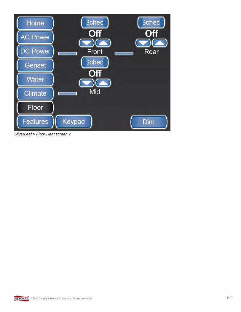
SilverLeaf > Floor Heat screen 2
© 2014 Copyright Newmar Corporation. All rights reserved. p.61
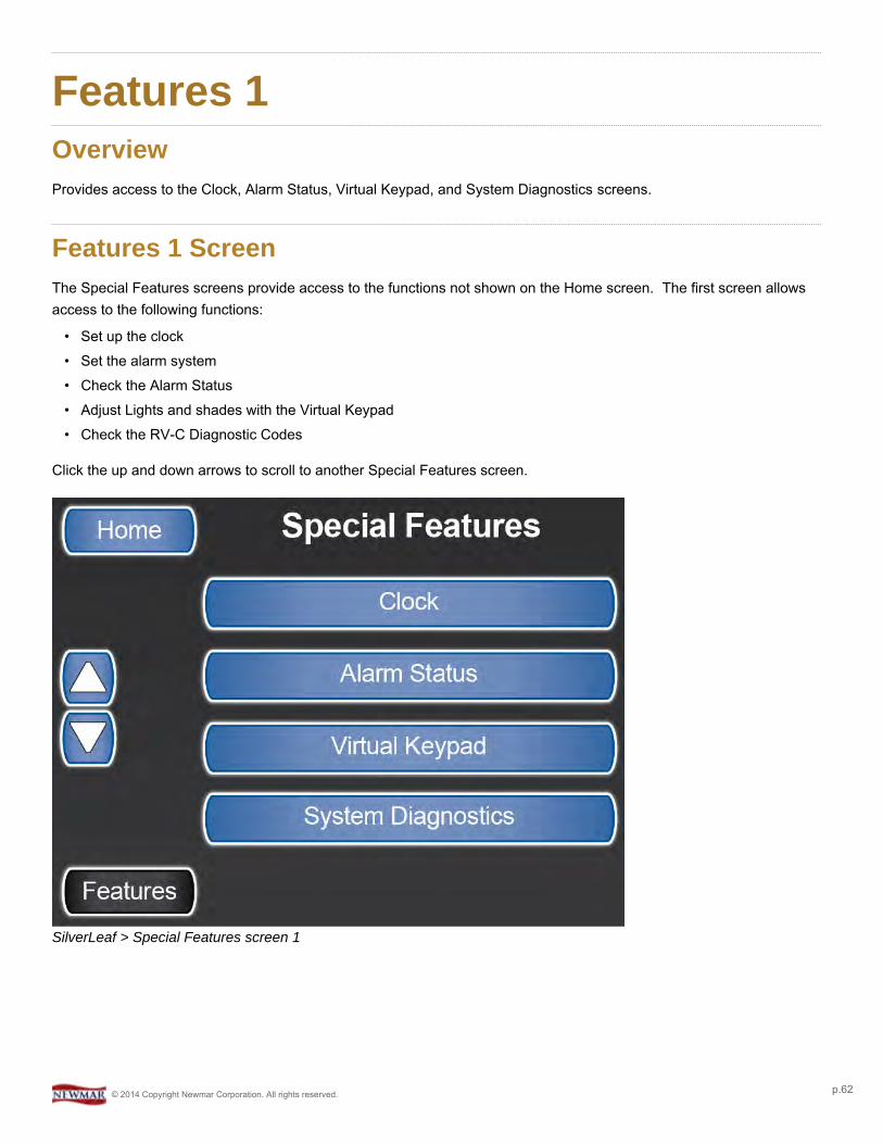
Features 1OverviewProvides access to the Clock, Alarm Status, Virtual Keypad, and System Diagnostics screens.
Features 1 ScreenThe Special Features screens provide access to the functions not shown on the Home screen. The first screen allowsaccess to the following functions:
• Set up the clock• Set the alarm system• Check the Alarm Status• Adjust Lights and shades with the Virtual Keypad• Check the RV-C Diagnostic Codes
Click the up and down arrows to scroll to another Special Features screen.
SilverLeaf > Special Features screen 1
© 2014 Copyright Newmar Corporation. All rights reserved. p.62
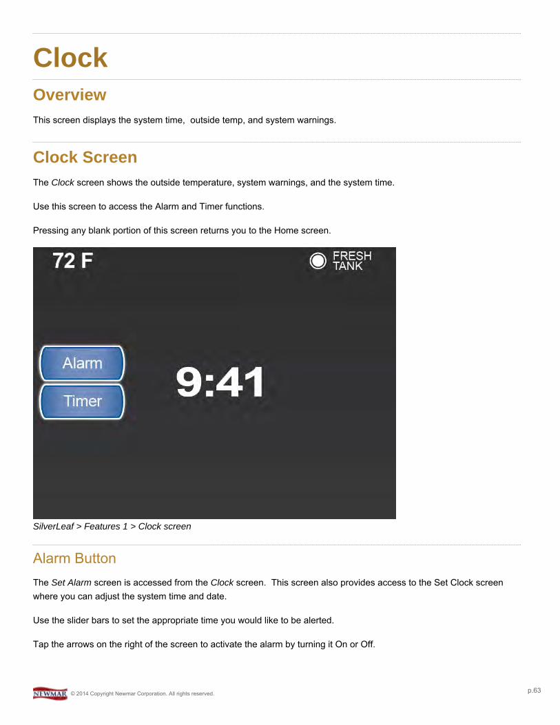
ClockOverviewThis screen displays the system time, outside temp, and system warnings.
Clock ScreenThe Clock screen shows the outside temperature, system warnings, and the system time.
Use this screen to access the Alarm and Timer functions.
Pressing any blank portion of this screen returns you to the Home screen.
SilverLeaf > Features 1 > Clock screen
Alarm ButtonThe Set Alarm screen is accessed from the Clock screen. This screen also provides access to the Set Clock screenwhere you can adjust the system time and date.
Use the slider bars to set the appropriate time you would like to be alerted.
Tap the arrows on the right of the screen to activate the alarm by turning it On or Off.
© 2014 Copyright Newmar Corporation. All rights reserved. p.63
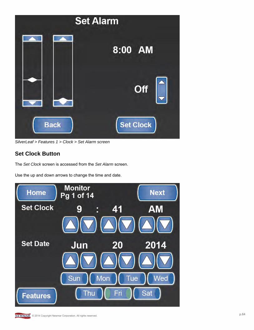
SilverLeaf > Features 1 > Clock > Set Alarm screen
Set Clock Button
The Set Clock screen is accessed from the Set Alarm screen.
Use the up and down arrows to change the time and date.
© 2014 Copyright Newmar Corporation. All rights reserved. p.64

SilverLeaf > Features 1 > Clock > Set Alarm > Set Clock screen
Timer ButtonThe Countdown Timer screen is accessed by pressing the Timer button from the Clock screen. This allows you to setthe countdown minutes and seconds.
Use the slider bars to set the appropriate time you would like to countdown.
To start the countdown, press the Start button. You will hear an audible sound when the timer reaches zero.
SilverLeaf > Features 1 > Clock > Countdown Timer screen
© 2014 Copyright Newmar Corporation. All rights reserved. p.65

Alarm StatusOverviewThe Alarm Status Screen shows the possible Alarms that have been activated.
Alarm Status ScreenThis setting shows system alarms that are either active or not active. The non-active ones are shown with a line throughthem.
SilverLeaf > Features 1 > Alarm Status screen
© 2014 Copyright Newmar Corporation. All rights reserved. p.66
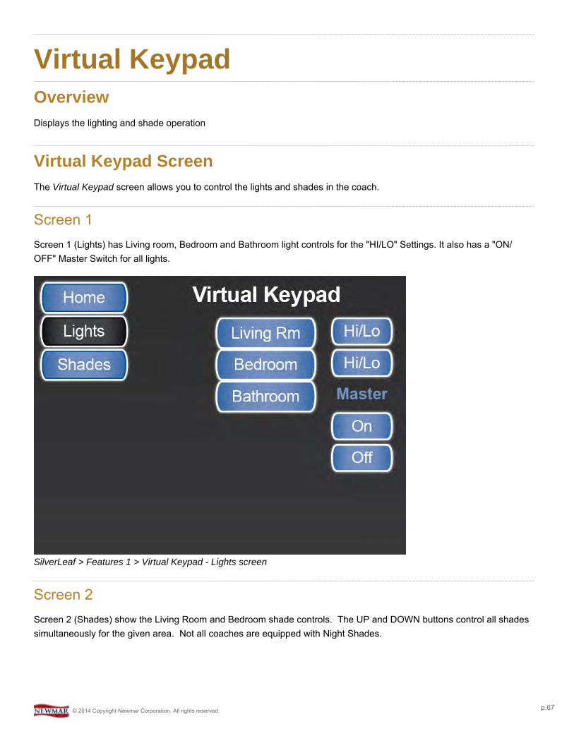
Virtual KeypadOverviewDisplays the lighting and shade operation
Virtual Keypad ScreenThe Virtual Keypad screen allows you to control the lights and shades in the coach.
Screen 1Screen 1 (Lights) has Living room, Bedroom and Bathroom light controls for the "HI/LO" Settings. It also has a "ON/OFF" Master Switch for all lights.
SilverLeaf > Features 1 > Virtual Keypad - Lights screen
Screen 2Screen 2 (Shades) show the Living Room and Bedroom shade controls. The UP and DOWN buttons control all shadessimultaneously for the given area. Not all coaches are equipped with Night Shades.
© 2014 Copyright Newmar Corporation. All rights reserved. p.67
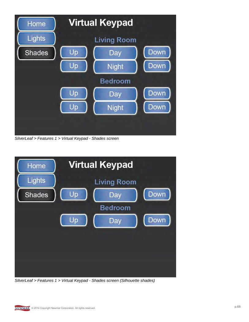
SilverLeaf > Features 1 > Virtual Keypad - Shades screen
SilverLeaf > Features 1 > Virtual Keypad - Shades screen (Silhouette shades)
© 2014 Copyright Newmar Corporation. All rights reserved. p.68

System DiagnosticsOverviewThese screens display system faults, communication status info, and additional system data.
System Diagnostics ScreenThere are three Diagnostics screens that display different information. To move through the screens, use the Next andPrevious buttons.
Screen 1Screen 1 displays any system faults present on the control system.
SilverLeaf > Features 1 > System Diagnostics screen 1
Screen 2Screen 2 displays the System Communication Status information.
Messages Received
This is Network Traffic Information from the RV-C Network.
© 2014 Copyright Newmar Corporation. All rights reserved. p.69
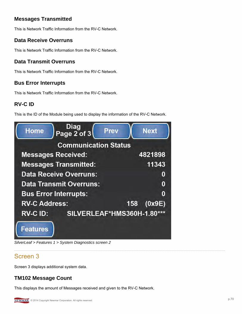
Messages Transmitted
This is Network Traffic Information from the RV-C Network.
Data Receive Overruns
This is Network Traffic Information from the RV-C Network.
Data Transmit Overruns
This is Network Traffic Information from the RV-C Network.
Bus Error Interrupts
This is Network Traffic Information from the RV-C Network.
RV-C ID
This is the ID of the Module being used to display the information of the RV-C Network.
SilverLeaf > Features 1 > System Diagnostics screen 2
Screen 3Screen 3 displays additional system data.
TM102 Message Count
This displays the amount of Messages received and given to the RV-C Network.
© 2014 Copyright Newmar Corporation. All rights reserved. p.70
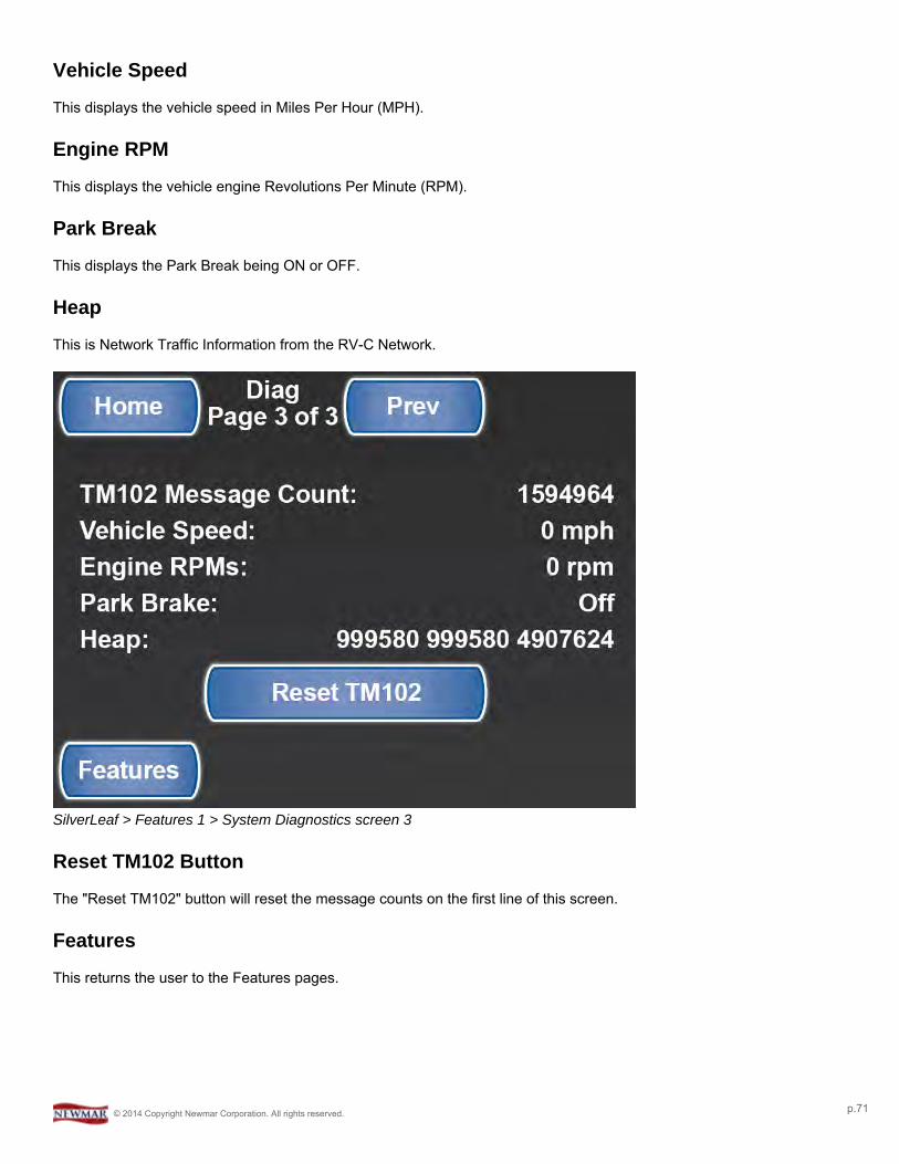
Vehicle Speed
This displays the vehicle speed in Miles Per Hour (MPH).
Engine RPM
This displays the vehicle engine Revolutions Per Minute (RPM).
Park Break
This displays the Park Break being ON or OFF.
Heap
This is Network Traffic Information from the RV-C Network.
SilverLeaf > Features 1 > System Diagnostics screen 3
Reset TM102 Button
The "Reset TM102" button will reset the message counts on the first line of this screen.
Features
This returns the user to the Features pages.
© 2014 Copyright Newmar Corporation. All rights reserved. p.71
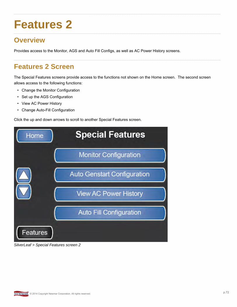
Features 2OverviewProvides access to the Monitor, AGS and Auto Fill Configs, as well as AC Power History screens.
Features 2 ScreenThe Special Features screens provide access to the functions not shown on the Home screen. The second screenallows access to the following functions:
• Change the Monitor Configuration• Set up the AGS Configuration• View AC Power History• Change Auto-Fill Configuration
Click the up and down arrows to scroll to another Special Features screen.
SilverLeaf > Special Features screen 2
© 2014 Copyright Newmar Corporation. All rights reserved. p.72
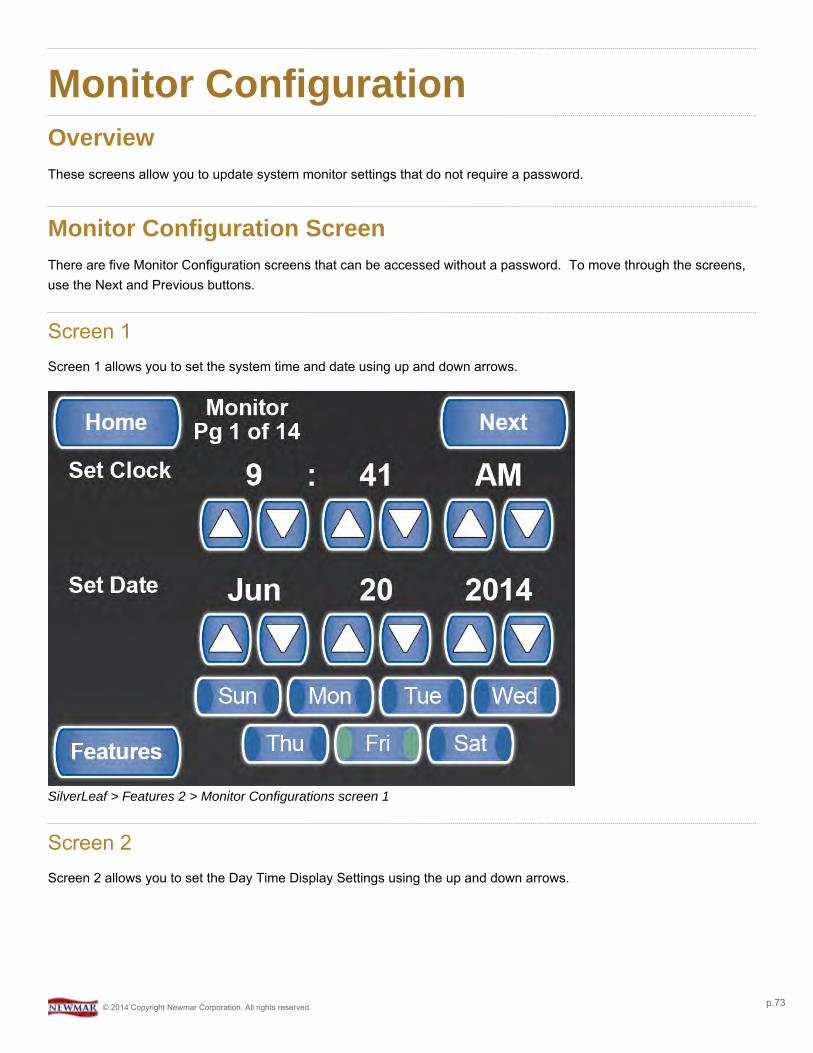
Monitor ConfigurationOverviewThese screens allow you to update system monitor settings that do not require a password.
Monitor Configuration ScreenThere are five Monitor Configuration screens that can be accessed without a password. To move through the screens,use the Next and Previous buttons.
Screen 1Screen 1 allows you to set the system time and date using up and down arrows.
SilverLeaf > Features 2 > Monitor Configurations screen 1
Screen 2Screen 2 allows you to set the Day Time Display Settings using the up and down arrows.
© 2014 Copyright Newmar Corporation. All rights reserved. p.73
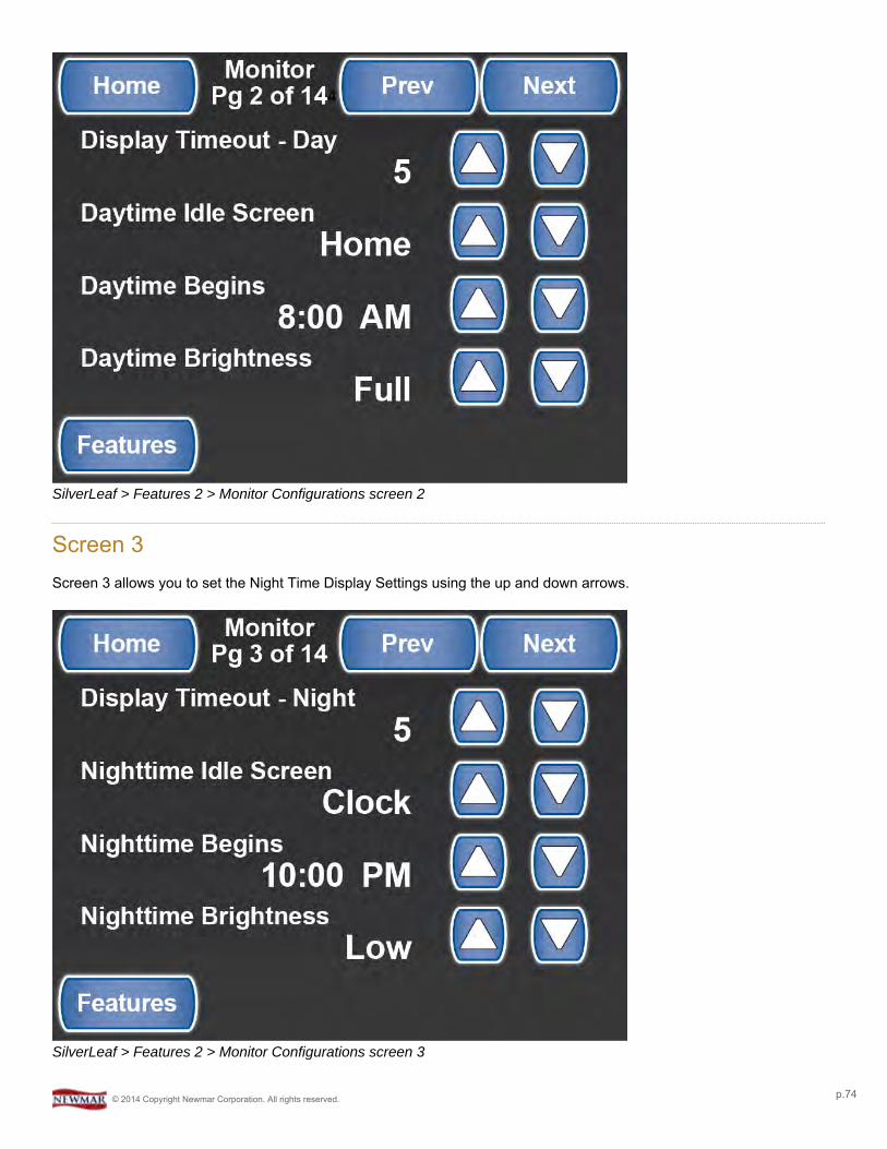
SilverLeaf > Features 2 > Monitor Configurations screen 2
Screen 3Screen 3 allows you to set the Night Time Display Settings using the up and down arrows.
SilverLeaf > Features 2 > Monitor Configurations screen 3
© 2014 Copyright Newmar Corporation. All rights reserved. p.74

Screen 4Screen 4 allows you to choose the color of the buttons shown on your display and set the speaker volume.
SilverLeaf > Features 2 > Monitor Configurations screen 4
Screen 5Screen 5 allows you to change Pop-Up alarms and Audible Alarms to Enable/Disable
© 2014 Copyright Newmar Corporation. All rights reserved. p.75
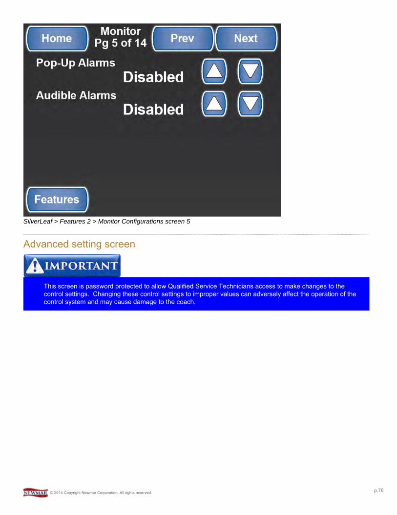
SilverLeaf > Features 2 > Monitor Configurations screen 5
Advanced setting screen
This screen is password protected to allow Qualified Service Technicians access to make changes to thecontrol settings. Changing these control settings to improper values can adversely affect the operation of thecontrol system and may cause damage to the coach.
© 2014 Copyright Newmar Corporation. All rights reserved. p.76
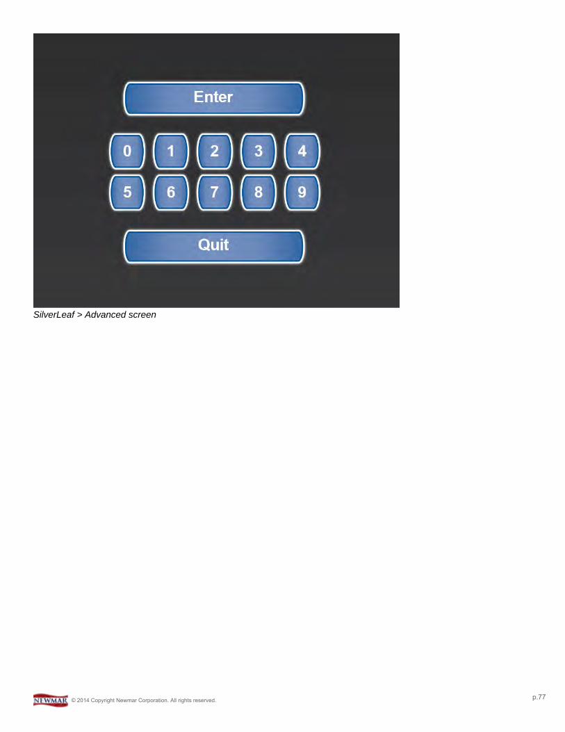
SilverLeaf > Advanced screen
© 2014 Copyright Newmar Corporation. All rights reserved. p.77
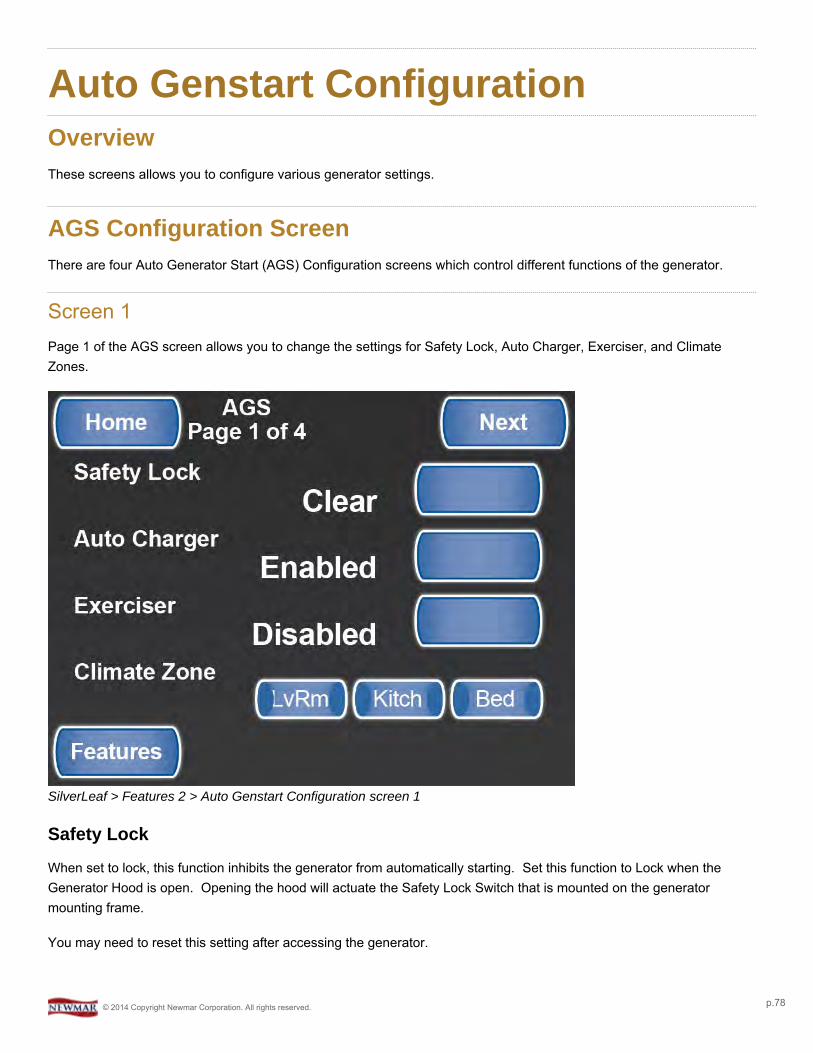
Auto Genstart ConfigurationOverviewThese screens allows you to configure various generator settings.
AGS Configuration ScreenThere are four Auto Generator Start (AGS) Configuration screens which control different functions of the generator.
Screen 1Page 1 of the AGS screen allows you to change the settings for Safety Lock, Auto Charger, Exerciser, and ClimateZones.
SilverLeaf > Features 2 > Auto Genstart Configuration screen 1
Safety Lock
When set to lock, this function inhibits the generator from automatically starting. Set this function to Lock when theGenerator Hood is open. Opening the hood will actuate the Safety Lock Switch that is mounted on the generatormounting frame.
You may need to reset this setting after accessing the generator.
© 2014 Copyright Newmar Corporation. All rights reserved. p.78
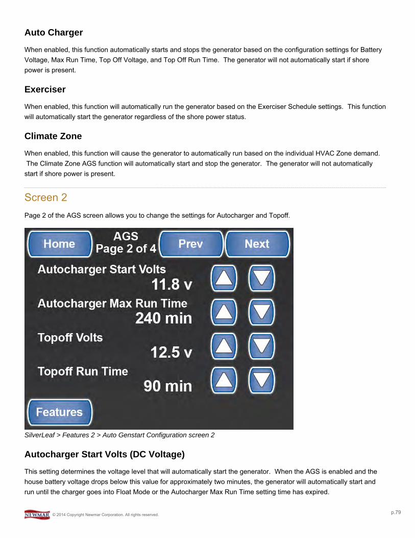
Auto Charger
When enabled, this function automatically starts and stops the generator based on the configuration settings for BatteryVoltage, Max Run Time, Top Off Voltage, and Top Off Run Time. The generator will not automatically start if shorepower is present.
Exerciser
When enabled, this function will automatically run the generator based on the Exerciser Schedule settings. This functionwill automatically start the generator regardless of the shore power status.
Climate Zone
When enabled, this function will cause the generator to automatically run based on the individual HVAC Zone demand.The Climate Zone AGS function will automatically start and stop the generator. The generator will not automatically
start if shore power is present.
Screen 2Page 2 of the AGS screen allows you to change the settings for Autocharger and Topoff.
SilverLeaf > Features 2 > Auto Genstart Configuration screen 2
Autocharger Start Volts (DC Voltage)
This setting determines the voltage level that will automatically start the generator. When the AGS is enabled and thehouse battery voltage drops below this value for approximately two minutes, the generator will automatically start andrun until the charger goes into Float Mode or the Autocharger Max Run Time setting time has expired.
© 2014 Copyright Newmar Corporation. All rights reserved. p.79

Autocharger Max Run Time
This setting controls how long the generator will run when started by the Autocharger function.
Topoff Volts (DC Voltage)
This setting determines the voltage level that will automatically start the generator based on the Topoff Run TimeSettings.
Topoff Run Time
This setting determines the amount of time before Quiet Time begins to automatically start the generator. It will run ifthe Autocharger function is enabled and the house battery voltage is below the Topoff Volts setting.
Screen 3Page 3 of the AGS screen allows you to change the settings for Quiet Time, Chassis Start Volts, and Charge BridgeDuration.
SilverLeaf > Features 2 > Auto Genstart Configuration screen 3
Quiet Time
Set the parameters for Quiet Time. The user can select the time to begin and end Quiet Time. Quiet Time is a timeinterval you set so that the Generator will not come on for any reason during the set time.
Chassis Start Voltage
The Chassis Start Voltage sets the DC voltage that automatically start the generator from low chassis battery voltage.
© 2014 Copyright Newmar Corporation. All rights reserved. p.80
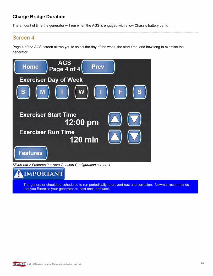
Charge Bridge Duration
The amount of time the generator will run when the AGS is engaged with a low Chassis battery bank.
Screen 4Page 4 of the AGS screen allows you to select the day of the week, the start time, and how long to exercise thegenerator.
SilverLeaf > Features 2 > Auto Genstart Configuration screen 4
The generator should be scheduled to run periodically to prevent rust and corrosion. Newmar recommendsthat you Exercise your generator at least once per week.
© 2014 Copyright Newmar Corporation. All rights reserved. p.81

AC Power HistoryOverviewDisplays the AC Power History for the coach
AC Power History ScreenThis screen is accessible from the second Features screen. It displays the AC Power History for the motor coach.
SilverLeaf > Features 2 > AC Power History screen
© 2014 Copyright Newmar Corporation. All rights reserved. p.82

Auto Fill ConfigurationOverviewFor altering Auto Fill settings.
Auto Fill Configuration Screen
This screen is password protected to allow Qualified Service Technicians access to make changes to thecontrol settings. Changing these control settings to improper values can adversely affect the operation of thecontrol system and may cause damage to the coach.
SilverLeaf > Advanced screen
© 2014 Copyright Newmar Corporation. All rights reserved. p.83
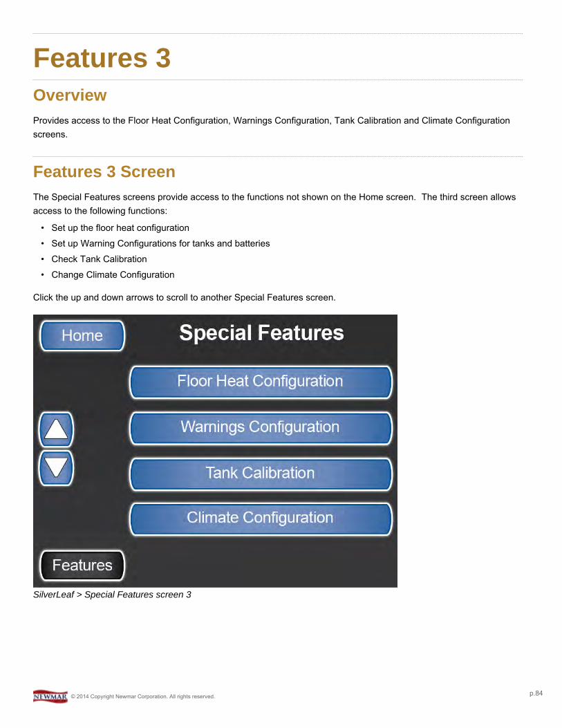
Features 3OverviewProvides access to the Floor Heat Configuration, Warnings Configuration, Tank Calibration and Climate Configurationscreens.
Features 3 ScreenThe Special Features screens provide access to the functions not shown on the Home screen. The third screen allowsaccess to the following functions:
• Set up the floor heat configuration• Set up Warning Configurations for tanks and batteries• Check Tank Calibration• Change Climate Configuration
Click the up and down arrows to scroll to another Special Features screen.
SilverLeaf > Special Features screen 3
© 2014 Copyright Newmar Corporation. All rights reserved. p.84

Floor Heat ConfigurationOverviewDisplays configuration settings for coaches equipped with Floor Heat.
Floor Heat Configuration ScreenThere are two Floor Heat Configuration screens. To move through the screens, use the Next and Previous buttons.
Screen 1Page 1 allows you to set the Day/Night Begin times and the Day/Night Setting ON/OFF.
SilverLeaf > Features 3 > Floor Heat Configuration screen 1
Screen 2If the coach is equipped with the Floor Heat option, Page 2 allows you to assign a Floor Heat Region and name it.
© 2014 Copyright Newmar Corporation. All rights reserved. p.85
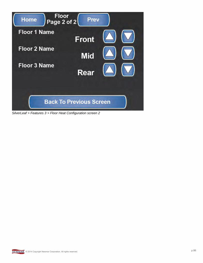
SilverLeaf > Features 3 > Floor Heat Configuration screen 2
© 2014 Copyright Newmar Corporation. All rights reserved. p.86
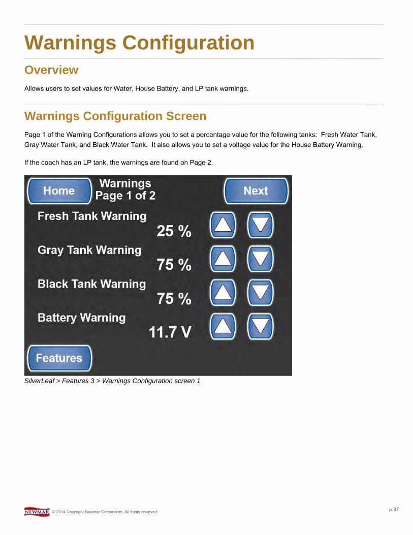
Warnings ConfigurationOverviewAllows users to set values for Water, House Battery, and LP tank warnings.
Warnings Configuration ScreenPage 1 of the Warning Configurations allows you to set a percentage value for the following tanks: Fresh Water Tank,Gray Water Tank, and Black Water Tank. It also allows you to set a voltage value for the House Battery Warning.
If the coach has an LP tank, the warnings are found on Page 2.
SilverLeaf > Features 3 > Warnings Configuration screen 1
© 2014 Copyright Newmar Corporation. All rights reserved. p.87
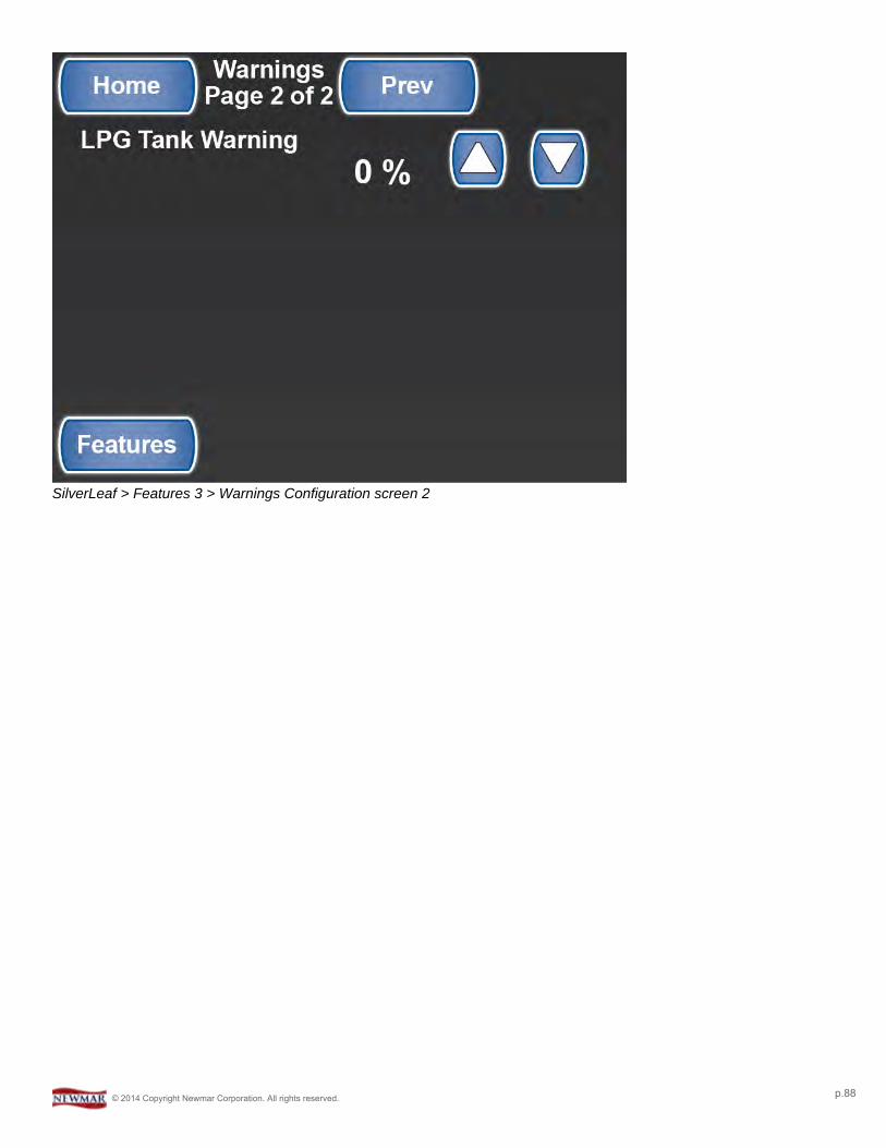
SilverLeaf > Features 3 > Warnings Configuration screen 2
© 2014 Copyright Newmar Corporation. All rights reserved. p.88
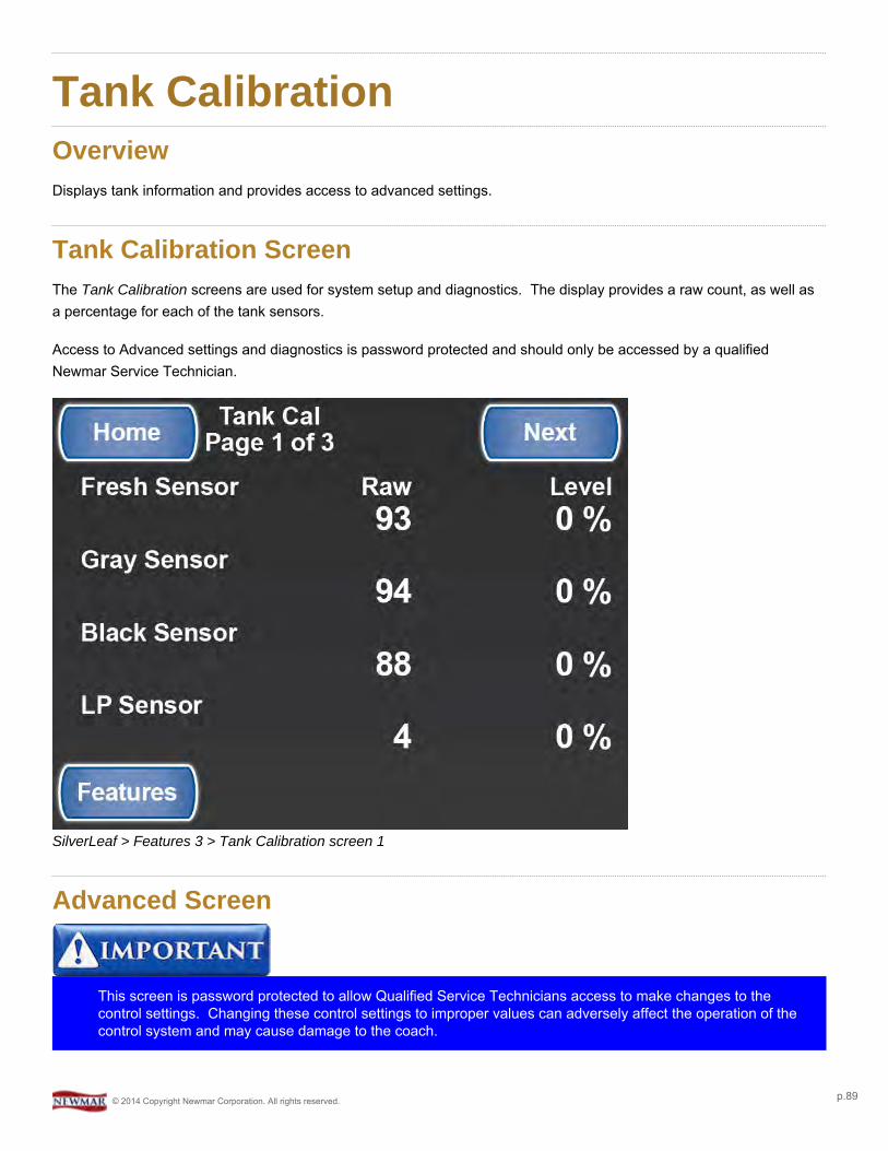
Tank CalibrationOverviewDisplays tank information and provides access to advanced settings.
Tank Calibration ScreenThe Tank Calibration screens are used for system setup and diagnostics. The display provides a raw count, as well asa percentage for each of the tank sensors.
Access to Advanced settings and diagnostics is password protected and should only be accessed by a qualifiedNewmar Service Technician.
SilverLeaf > Features 3 > Tank Calibration screen 1
Advanced Screen
This screen is password protected to allow Qualified Service Technicians access to make changes to thecontrol settings. Changing these control settings to improper values can adversely affect the operation of thecontrol system and may cause damage to the coach.
© 2014 Copyright Newmar Corporation. All rights reserved. p.89

SilverLeaf > Advanced screen
© 2014 Copyright Newmar Corporation. All rights reserved. p.90
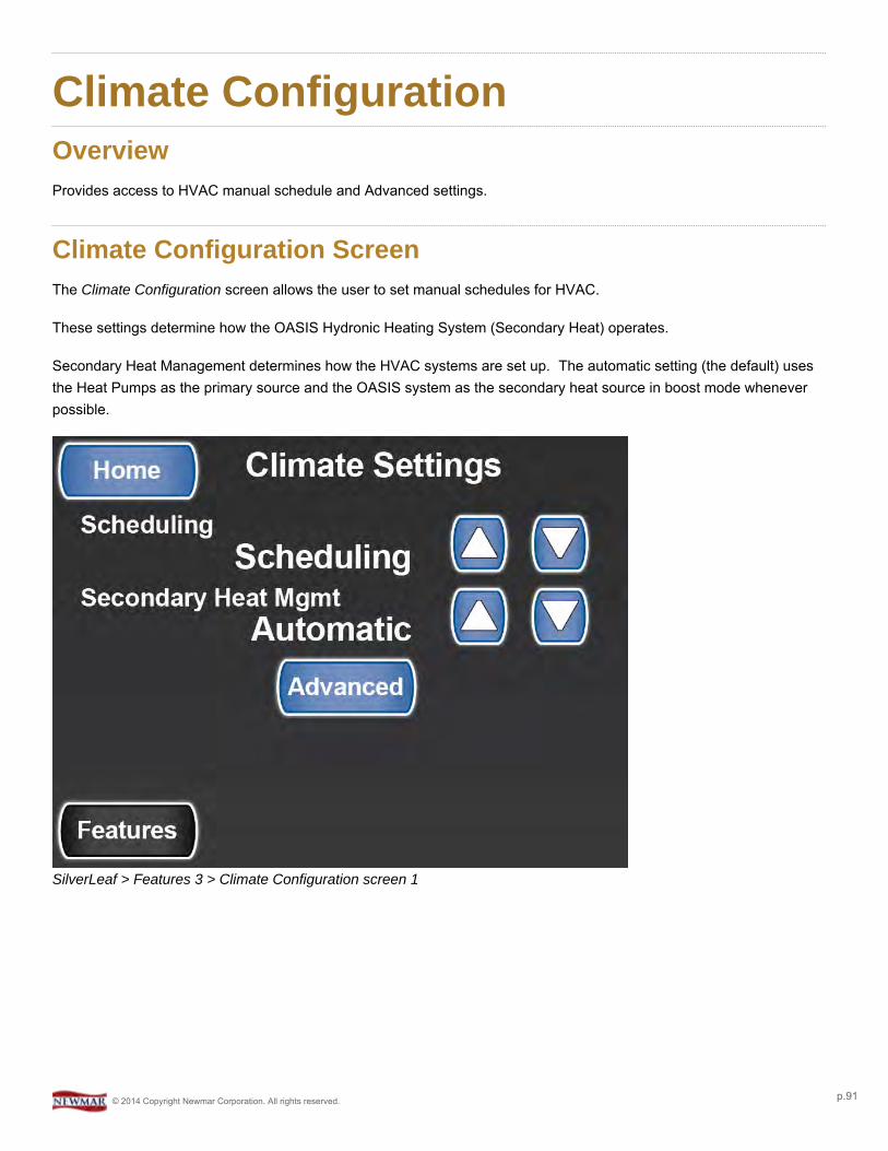
Climate ConfigurationOverviewProvides access to HVAC manual schedule and Advanced settings.
Climate Configuration ScreenThe Climate Configuration screen allows the user to set manual schedules for HVAC.
These settings determine how the OASIS Hydronic Heating System (Secondary Heat) operates.
Secondary Heat Management determines how the HVAC systems are set up. The automatic setting (the default) usesthe Heat Pumps as the primary source and the OASIS system as the secondary heat source in boost mode wheneverpossible.
SilverLeaf > Features 3 > Climate Configuration screen 1
© 2014 Copyright Newmar Corporation. All rights reserved. p.91
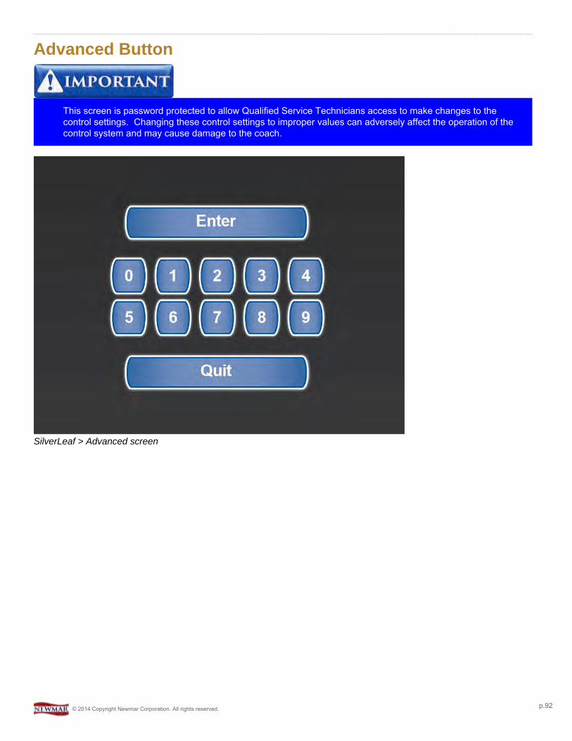
Advanced Button
This screen is password protected to allow Qualified Service Technicians access to make changes to thecontrol settings. Changing these control settings to improper values can adversely affect the operation of thecontrol system and may cause damage to the coach.
SilverLeaf > Advanced screen
© 2014 Copyright Newmar Corporation. All rights reserved. p.92
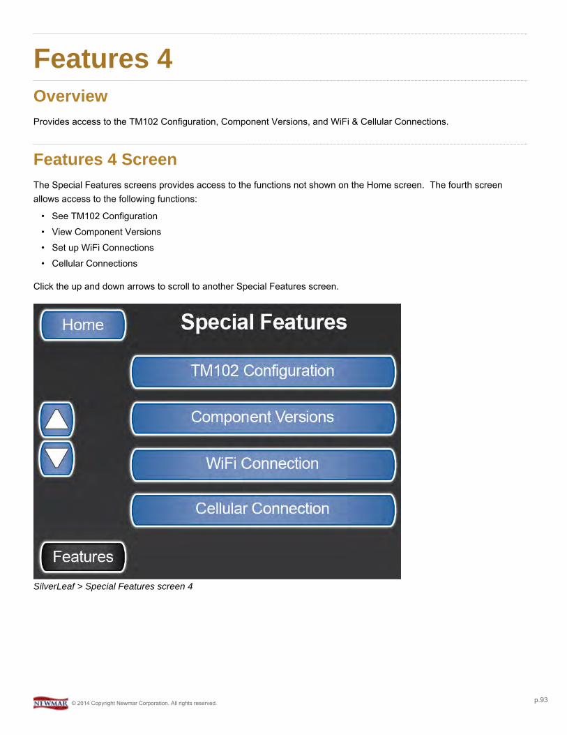
Features 4OverviewProvides access to the TM102 Configuration, Component Versions, and WiFi & Cellular Connections.
Features 4 ScreenThe Special Features screens provides access to the functions not shown on the Home screen. The fourth screenallows access to the following functions:
• See TM102 Configuration• View Component Versions• Set up WiFi Connections• Cellular Connections
Click the up and down arrows to scroll to another Special Features screen.
SilverLeaf > Special Features screen 4
© 2014 Copyright Newmar Corporation. All rights reserved. p.93
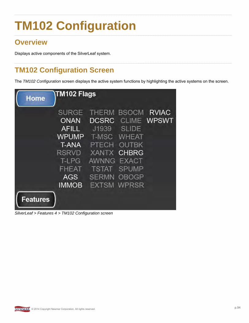
TM102 ConfigurationOverviewDisplays active components of the SilverLeaf system.
TM102 Configuration ScreenThe TM102 Configuration screen displays the active system functions by highlighting the active systems on the screen.
SilverLeaf > Features 4 > TM102 Configuration screen
© 2014 Copyright Newmar Corporation. All rights reserved. p.94

Component VersionsOverviewDisplays information about each of the SilverLeaf modules.
Component Versions ScreenThe Component Versions screens display all of the RV-C Modules and their firmware versions that are found on themotor coach.
Pressing the "More" button shows additional components.
SilverLeaf > Features 4 > Component Versions screen 1
© 2014 Copyright Newmar Corporation. All rights reserved. p.95

SilverLeaf > Features 4 > Component Versions screen 2
© 2014 Copyright Newmar Corporation. All rights reserved. p.96
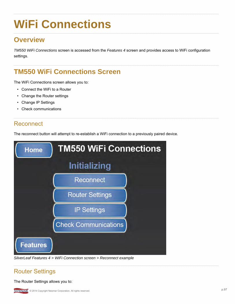
WiFi ConnectionsOverviewTM550 WiFi Connections screen is accessed from the Features 4 screen and provides access to WiFi configurationsettings.
TM550 WiFi Connections ScreenThe WiFi Connections screen allows you to:
• Connect the WiFi to a Router• Change the Router settings• Change IP Settings• Check communications
ReconnectThe reconnect button will attempt to re-establish a WiFi connection to a previously paired device.
SilverLeaf Features 4 > WiFi Connection screen > Reconnect example
Router SettingsThe Router Settings allows you to:
© 2014 Copyright Newmar Corporation. All rights reserved. p.97
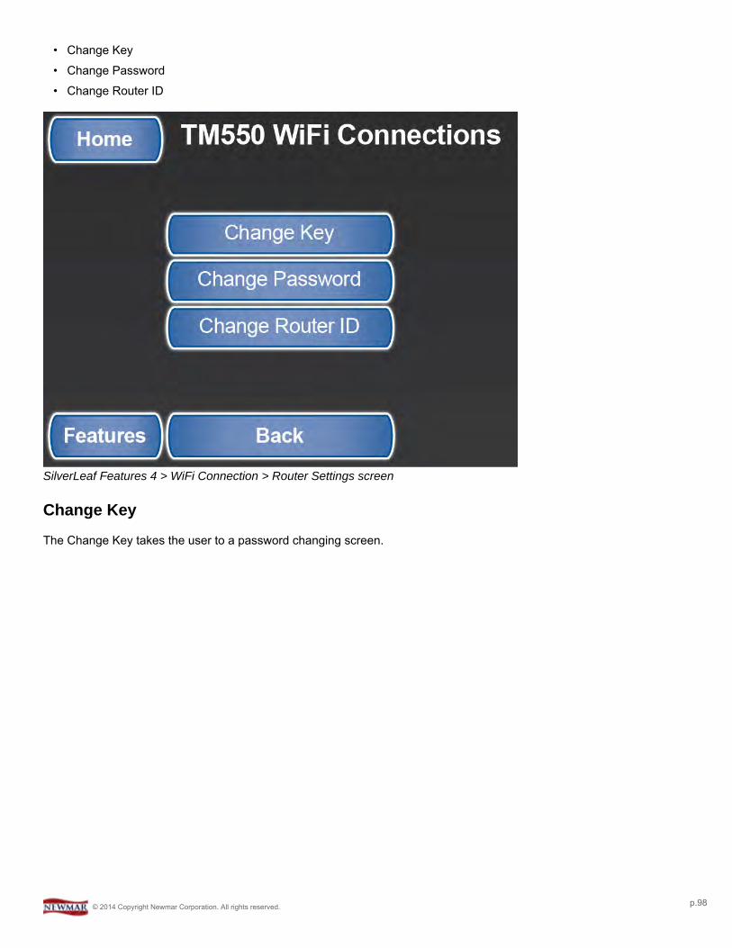
• Change Key• Change Password• Change Router ID
SilverLeaf Features 4 > WiFi Connection > Router Settings screen
Change Key
The Change Key takes the user to a password changing screen.
© 2014 Copyright Newmar Corporation. All rights reserved. p.98
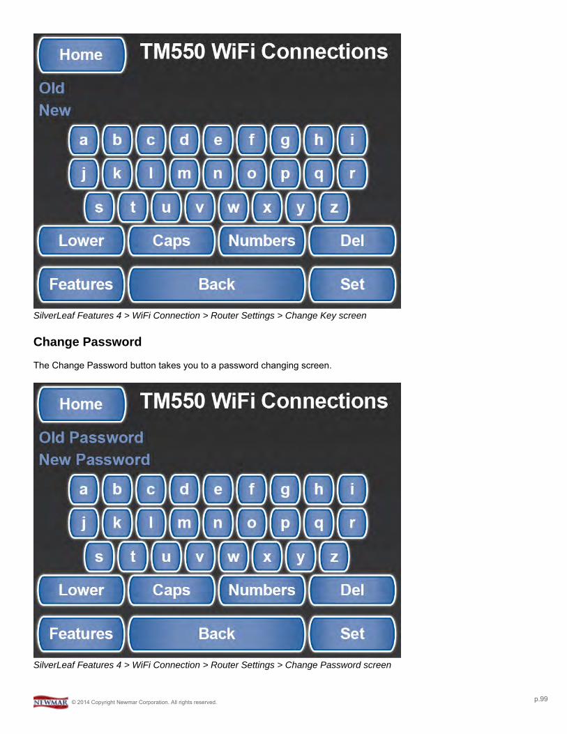
SilverLeaf Features 4 > WiFi Connection > Router Settings > Change Key screen
Change Password
The Change Password button takes you to a password changing screen.
SilverLeaf Features 4 > WiFi Connection > Router Settings > Change Password screen
© 2014 Copyright Newmar Corporation. All rights reserved. p.99
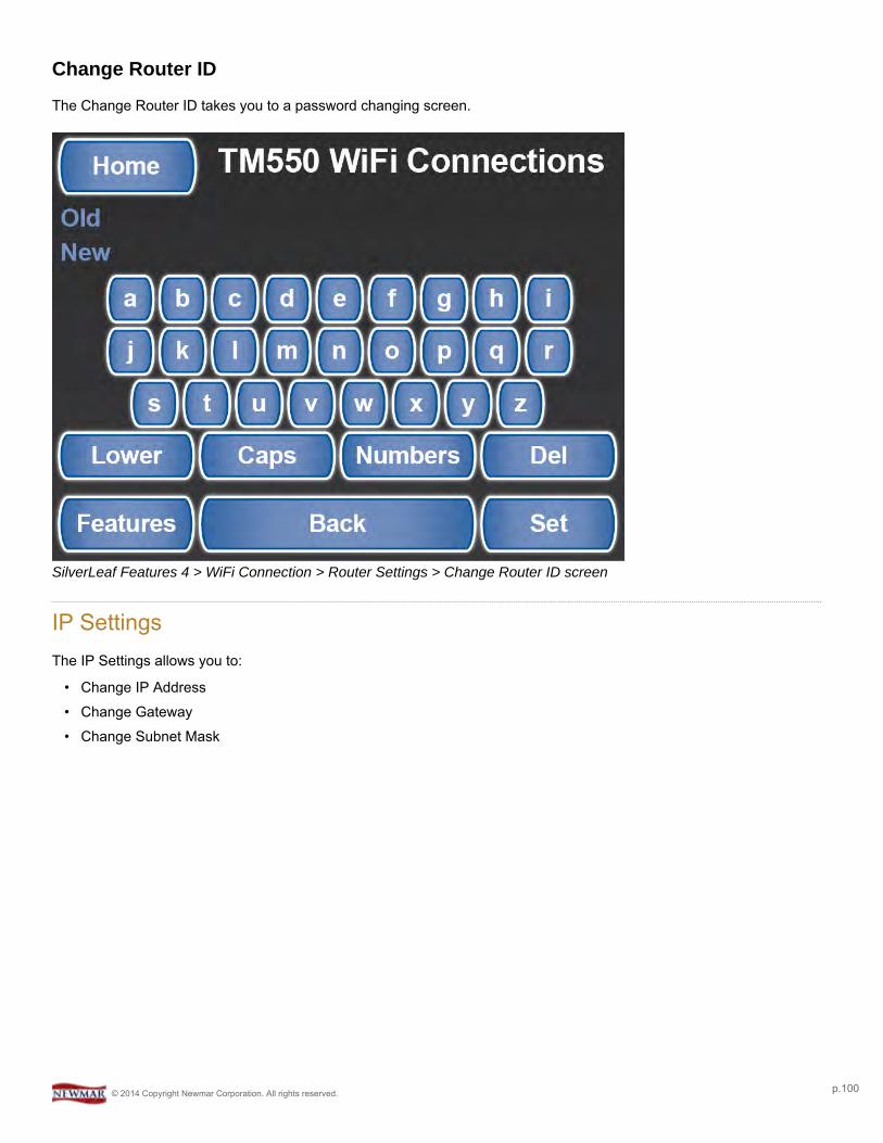
Change Router ID
The Change Router ID takes you to a password changing screen.
SilverLeaf Features 4 > WiFi Connection > Router Settings > Change Router ID screen
IP SettingsThe IP Settings allows you to:
• Change IP Address• Change Gateway• Change Subnet Mask
© 2014 Copyright Newmar Corporation. All rights reserved. p.100
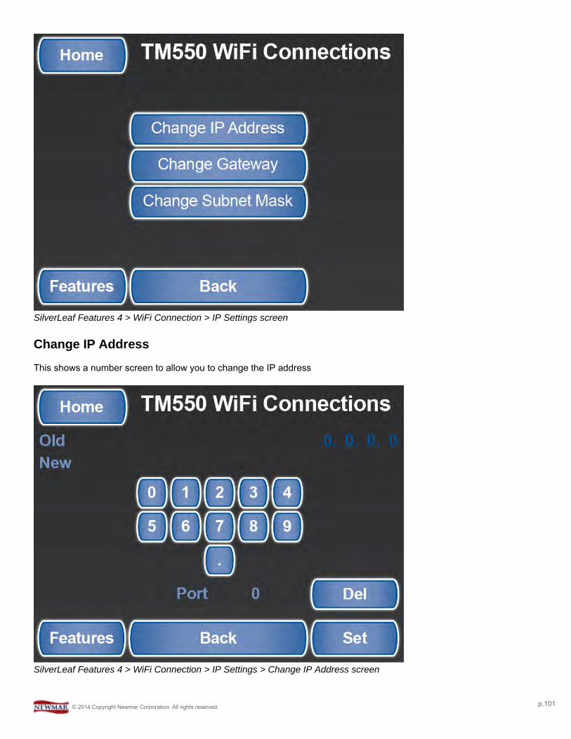
SilverLeaf Features 4 > WiFi Connection > IP Settings screen
Change IP Address
This shows a number screen to allow you to change the IP address
SilverLeaf Features 4 > WiFi Connection > IP Settings > Change IP Address screen
© 2014 Copyright Newmar Corporation. All rights reserved. p.101
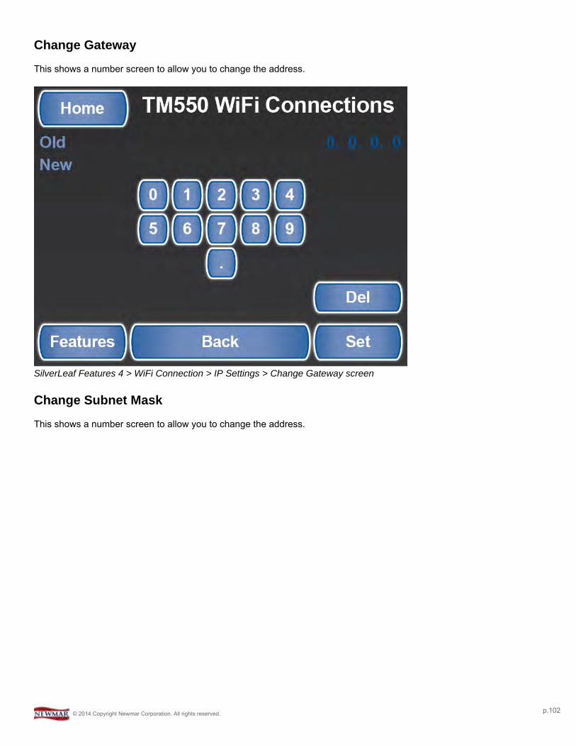
Change Gateway
This shows a number screen to allow you to change the address.
SilverLeaf Features 4 > WiFi Connection > IP Settings > Change Gateway screen
Change Subnet Mask
This shows a number screen to allow you to change the address.
© 2014 Copyright Newmar Corporation. All rights reserved. p.102
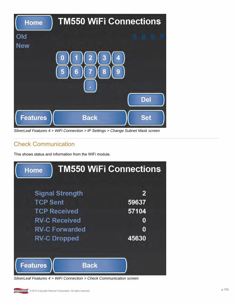
SilverLeaf Features 4 > WiFi Connection > IP Settings > Change Subnet Mask screen
Check CommunicationThis shows status and information from the WiFi module.
SilverLeaf Features 4 > WiFi Connection > Check Communication screen
© 2014 Copyright Newmar Corporation. All rights reserved. p.103
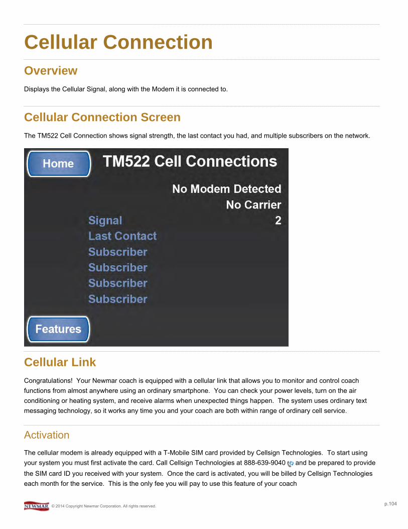
Cellular ConnectionOverviewDisplays the Cellular Signal, along with the Modem it is connected to.
Cellular Connection ScreenThe TM522 Cell Connection shows signal strength, the last contact you had, and multiple subscribers on the network.
Cellular LinkCongratulations! Your Newmar coach is equipped with a cellular link that allows you to monitor and control coachfunctions from almost anywhere using an ordinary smartphone. You can check your power levels, turn on the airconditioning or heating system, and receive alarms when unexpected things happen. The system uses ordinary textmessaging technology, so it works any time you and your coach are both within range of ordinary cell service.
ActivationThe cellular modem is already equipped with a T-Mobile SIM card provided by Cellsign Technologies. To start usingyour system you must first activate the card. Call Cellsign Technologies at 888-639-9040 and be prepared to providethe SIM card ID you received with your system. Once the card is activated, you will be billed by Cellsign Technologieseach month for the service. This is the only fee you will pay to use this feature of your coach
© 2014 Copyright Newmar Corporation. All rights reserved. p.104

Cellsign has selected T-Mobile for their long-term commitment to supporting the text messaging protocols used by thistype of equipment. Contact the carrier for more information, and inform them that you want a text and MMS plan (“2G”)with absolutely no other services – no voice, no data.
Be sure that not only is voice service turned OFF, but voice-oriented features such as Voicemail orCall Forwarding are turned OFF as well. These features can interfere with the routing of messages to your unit.
ApplicationTo make the best use of your system, SilverLeaf Electronics has created applications for Android and Applesmartphones. The applications can be found on Google Play and the iTunes store under “SilverLeaf Electronics”. Lookfor the Newmar “RVC Cellular Client” application.
Installation
Once the application is downloaded, follow these instructions.
1. Enter your modem's phone number into the application. (You will receive a phone number when you activate theSIM card.)
2. Take “Super Administrative Control” of the modem by selecting that option from the application menu. Only onephone can be the SuperAdmin, and this phone controls access for all other phones.
3. If you wish to use multiple phones, using the SuperAdmin phone, select “Enable Another Phone”. Up to fourphones may be enabled, and the SuperAdmin can enable and disable phones at any time.
If you chance SIM cards, sell the coach, or change phones, remember to “Surrender All Control” with theSuperAdmin phone.
App Use
Get Coach Info
To get information on your coach systems, press the appropriate button in the application. For Android, press “Refresh”and the system will download all the coach data and display it on the screen. For iPhone, only a portion of the data canbe retrieved at a time and is displayed in text form.
Change Climate Settings
To make climate settings, press the appropriate button and if prompted, enter the desired temperature. You will receivea confirmation after a small delay.
© 2014 Copyright Newmar Corporation. All rights reserved. p.105
Get Video Image
To get a video image from the coach cameras, press the appropriate button. For iPhone, you must select the camerafirst, then after the switch has been confirmed, take the picture. Android users have the two stepscombined automatically.
Arm/Disarm Alarms
To use the alarm feature, first enable or disable the alarms desired (Low battery, High Interior Temperature, LowExterior Temperature). Then select “Arm Alarms” when you leave the coach, and “Disarm Alarms” when you return.
Alarm parameters are set at the Newmar factory.
How the App Works
The application works by sending coded messages to the modem. These messages are processed and the modemtexts back an appropriate response. Like all text messaging there can be delays from a few seconds to over a minutefor the message to traverse the cellular network.
On iPhones, for security reasons Apple does not allow the application to send a text message without an additionalconfirmation step. Every time the application wants to send a message the phone will display the message to you. Justpress “Send” eachtime.
The system can be used on any phone that supports text messaging. The application is simply a convenience availablefor smartphone users. Consult the system manual for more information.
© 2014 Copyright Newmar Corporation. All rights reserved. p.106
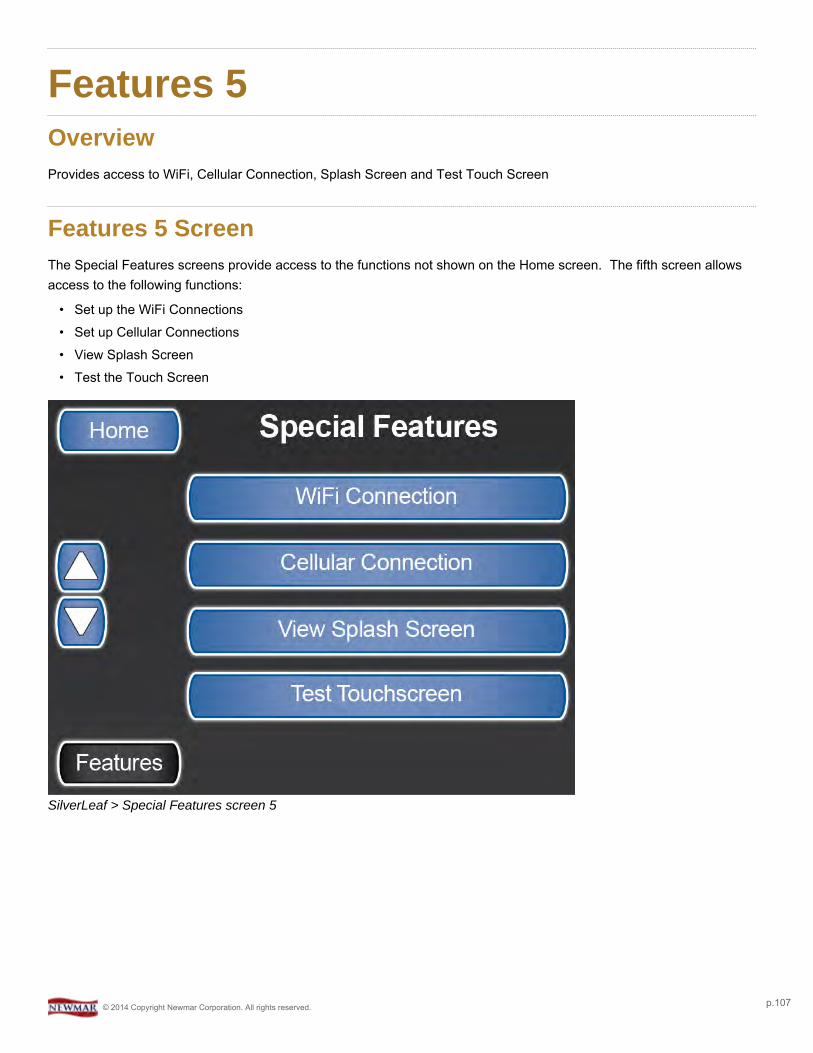
Features 5OverviewProvides access to WiFi, Cellular Connection, Splash Screen and Test Touch Screen
Features 5 ScreenThe Special Features screens provide access to the functions not shown on the Home screen. The fifth screen allowsaccess to the following functions:
• Set up the WiFi Connections• Set up Cellular Connections• View Splash Screen• Test the Touch Screen
SilverLeaf > Special Features screen 5
© 2014 Copyright Newmar Corporation. All rights reserved. p.107
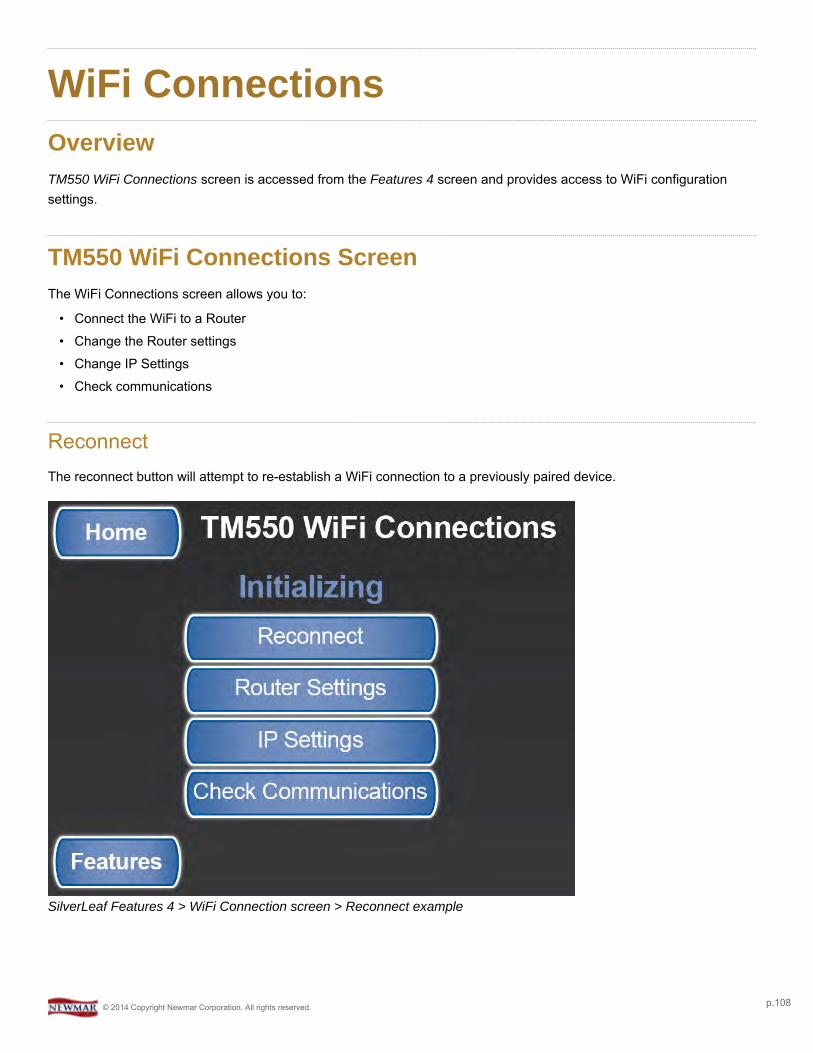
WiFi ConnectionsOverviewTM550 WiFi Connections screen is accessed from the Features 4 screen and provides access to WiFi configurationsettings.
TM550 WiFi Connections ScreenThe WiFi Connections screen allows you to:
• Connect the WiFi to a Router• Change the Router settings• Change IP Settings• Check communications
ReconnectThe reconnect button will attempt to re-establish a WiFi connection to a previously paired device.
SilverLeaf Features 4 > WiFi Connection screen > Reconnect example
© 2014 Copyright Newmar Corporation. All rights reserved. p.108
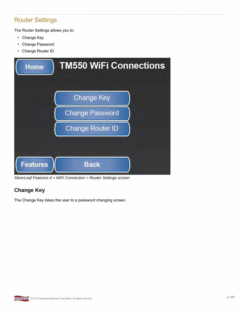
Router SettingsThe Router Settings allows you to:
• Change Key• Change Password• Change Router ID
SilverLeaf Features 4 > WiFi Connection > Router Settings screen
Change Key
The Change Key takes the user to a password changing screen.
© 2014 Copyright Newmar Corporation. All rights reserved. p.109

SilverLeaf Features 4 > WiFi Connection > Router Settings > Change Key screen
Change Password
The Change Password button takes you to a password changing screen.
SilverLeaf Features 4 > WiFi Connection > Router Settings > Change Password screen
© 2014 Copyright Newmar Corporation. All rights reserved. p.110

Change Router ID
The Change Router ID takes you to a password changing screen.
SilverLeaf Features 4 > WiFi Connection > Router Settings > Change Router ID screen
IP SettingsThe IP Settings allows you to:
• Change IP Address• Change Gateway• Change Subnet Mask
© 2014 Copyright Newmar Corporation. All rights reserved. p.111

SilverLeaf Features 4 > WiFi Connection > IP Settings screen
Change IP Address
This shows a number screen to allow you to change the IP address
SilverLeaf Features 4 > WiFi Connection > IP Settings > Change IP Address screen
© 2014 Copyright Newmar Corporation. All rights reserved. p.112

Change Gateway
This shows a number screen to allow you to change the address.
SilverLeaf Features 4 > WiFi Connection > IP Settings > Change Gateway screen
Change Subnet Mask
This shows a number screen to allow you to change the address.
© 2014 Copyright Newmar Corporation. All rights reserved. p.113

SilverLeaf Features 4 > WiFi Connection > IP Settings > Change Subnet Mask screen
Check CommunicationThis shows status and information from the WiFi module.
SilverLeaf Features 4 > WiFi Connection > Check Communication screen
© 2014 Copyright Newmar Corporation. All rights reserved. p.114

Cellular ConnectionOverviewDisplays the Cellular Signal, along with the Modem it is connected to.
Cellular Connection ScreenThe TM522 Cell Connection shows signal strength, the last contact you had, and multiple subscribers on the network.
Cellular LinkCongratulations! Your Newmar coach is equipped with a cellular link that allows you to monitor and control coachfunctions from almost anywhere using an ordinary smartphone. You can check your power levels, turn on the airconditioning or heating system, and receive alarms when unexpected things happen. The system uses ordinary textmessaging technology, so it works any time you and your coach are both within range of ordinary cell service.
ActivationThe cellular modem is already equipped with a T-Mobile SIM card provided by Cellsign Technologies. To start usingyour system you must first activate the card. Call Cellsign Technologies at 888-639-9040 and be prepared to providethe SIM card ID you received with your system. Once the card is activated, you will be billed by Cellsign Technologieseach month for the service. This is the only fee you will pay to use this feature of your coach
© 2014 Copyright Newmar Corporation. All rights reserved. p.115
Cellsign has selected T-Mobile for their long-term commitment to supporting the text messaging protocols used by thistype of equipment. Contact the carrier for more information, and inform them that you want a text and MMS plan (“2G”)with absolutely no other services – no voice, no data.
Be sure that not only is voice service turned OFF, but voice-oriented features such as Voicemail orCall Forwarding are turned OFF as well. These features can interfere with the routing of messages to your unit.
ApplicationTo make the best use of your system, SilverLeaf Electronics has created applications for Android and Applesmartphones. The applications can be found on Google Play and the iTunes store under “SilverLeaf Electronics”. Lookfor the Newmar “RVC Cellular Client” application.
Installation
Once the application is downloaded, follow these instructions.
1. Enter your modem's phone number into the application. (You will receive a phone number when you activate theSIM card.)
2. Take “Super Administrative Control” of the modem by selecting that option from the application menu. Only onephone can be the SuperAdmin, and this phone controls access for all other phones.
3. If you wish to use multiple phones, using the SuperAdmin phone, select “Enable Another Phone”. Up to fourphones may be enabled, and the SuperAdmin can enable and disable phones at any time.
If you chance SIM cards, sell the coach, or change phones, remember to “Surrender All Control” with theSuperAdmin phone.
App Use
Get Coach Info
To get information on your coach systems, press the appropriate button in the application. For Android, press “Refresh”and the system will download all the coach data and display it on the screen. For iPhone, only a portion of the data canbe retrieved at a time and is displayed in text form.
Change Climate Settings
To make climate settings, press the appropriate button and if prompted, enter the desired temperature. You will receivea confirmation after a small delay.
© 2014 Copyright Newmar Corporation. All rights reserved. p.116
Get Video Image
To get a video image from the coach cameras, press the appropriate button. For iPhone, you must select the camerafirst, then after the switch has been confirmed, take the picture. Android users have the two stepscombined automatically.
Arm/Disarm Alarms
To use the alarm feature, first enable or disable the alarms desired (Low battery, High Interior Temperature, LowExterior Temperature). Then select “Arm Alarms” when you leave the coach, and “Disarm Alarms” when you return.
Alarm parameters are set at the Newmar factory.
How the App Works
The application works by sending coded messages to the modem. These messages are processed and the modemtexts back an appropriate response. Like all text messaging there can be delays from a few seconds to over a minutefor the message to traverse the cellular network.
On iPhones, for security reasons Apple does not allow the application to send a text message without an additionalconfirmation step. Every time the application wants to send a message the phone will display the message to you. Justpress “Send” eachtime.
The system can be used on any phone that supports text messaging. The application is simply a convenience availablefor smartphone users. Consult the system manual for more information.
© 2014 Copyright Newmar Corporation. All rights reserved. p.117

View Splash ScreenOverviewDisplays the Newmar Logo Splash screen.
Splash ScreenDisplays the Newmar Logo Splash screen. Tap anywhere on the screen to return to Special Features.
SilverLeaf > Features 5 > View Splash Screen
© 2014 Copyright Newmar Corporation. All rights reserved. p.118

Test TouchscreenOverviewProvides the ability to recalibrate the touch interface.
Test Touchscreen ScreenThe Test Touchscreen feature allows you to recalibrate the touch interface with the display by following the prompts totap on various points on the screen.
SilverLeaf > Features 5 > Test Touchscreen
© 2014 Copyright Newmar Corporation. All rights reserved. p.119

Driver DisplayOverviewThe Driver Display feature provides the driver with convenient access to SilverLeaf functions and settings, as well asengine data, tire pressures, and more.
Driver DisplayThe SilverLeaf Driver Display is located on the dash and is easily accessible to the driver. The driver has the capabilityto look at all the exterior coach cameras and also change settings in SilverLeaf, just as they can with the main display inthe cockpit, overhead compartment, and the optional bedroom display.
SilverLeaf Dash Keypad and Driver Displays
Control Keypad
SilverLeaf Dash Keypad
© 2014 Copyright Newmar Corporation. All rights reserved. p.1

Control KnobTurn the Control Knob to change your feature selection or to change a value on the screen. Press the Control Knob tochange the cursor from one mode, Navigation, to the other, Adjustment.
Navigation
When the cursor has a triangular shape, turning the knob will move the cursor up or down the page.
Adjustment
When the cursor looks like a circular arrow pointing at its tail, turning the knob will adjust the selectedsetting.
Home (SilverLeaf Logo)The Silverleaf logo (aka Home) button switches the display to show the main gauge screen. Pressing the button asecond time switches to the Configuration screen, which allows you to configure the date, time, unit of measure, and tiresensors, as well as clear trip and diagnostic history and view communications.
ViewThe 'View' button changes whether the vehicle information or one of the exterior cameras (or both) is displayed on thevideo screen, with or without a camera image in the background. If you press it repeatedly, the unit will cycle throughthe different viewing modes, as well as the rear and side-view cameras.
HouseThe 'House' button switches the display to show the House settings and readouts such as Tanks, Generator, AC Power,DC Power, and Floor Heat (if equipped).
ThermThe 'Therm' button switches the display to show the HVAC settings that are controlled by SilverLeaf.
ChassisThe 'Chass' button changes the display to show the Tire Pressure, Chassis Statistics & Metrics, and Diagnostics pages.
TripThe 'Trip' button switches the display to show current trip statistics, along with the ability to reset stats or view prior trips.
© 2014 Copyright Newmar Corporation. All rights reserved. p.2

Home :: GaugesOverviewThis screen allows you to view the status of the most popular and important features at a glance.
Home Screen - GaugesPress the Home button (SilverLeaf logo) on the control keypad to display the Gauges screen.
SilverLeaf Driver Display > Home button > Gauges screen
Upper SectionThe top portion of the screen displays five different engine and transmission parameters per page. Three unique pagesthen allow for a static choice at the top, such as SPEED, and four others below it. Rotate the knob on the controlkeypad to change the selected gauge to display, then press the knob to make your selection. Turn the knob again toselect another gauge, then press the knob to complete the selection.
NOTE: Due to variations in engine configurations, some of the gauges included in the VMS350 might not be supported.
Whereas most of the gauges are read directly from the engine and transmission, a few gauges are unique to theVMS350. In particular, the "Recent MPG" and "Real MPG" are special data items calculated by the VMS350 to help getthe best possible fuel economy.
"Real MPG" shows the fuel economy over roughly the last minute or so, and is intended to allow for adjusting drivingtechnique to realize better fuel economy with headwinds and hills. "Recent MPG" shows the fuel economy over a muchlonger period and provides a good indication of what driving strategy is working overall.
© 2014 Copyright Newmar Corporation. All rights reserved. p.3
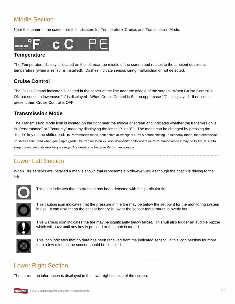
Middle SectionNear the center of the screen are the indicators for Temperature, Cruise, and Transmission Mode.
Temperature
The Temperature display is located on the left near the middle of the screen and relates to the ambient outside airtemperature (when a sensor is installed). Dashes indicate sensor/wiring malfunction or not detected.
Cruise Control
The Cruise Control indicator is located in the center of the line near the middle of the screen. When Cruise Control isON but not set a lowercase "c" is displayed. When Cruise Control is Set an uppercase "C" is displayed. If no icon ispresent then Cruise Control is OFF.
Transmission Mode
The Transmission Mode icon is located on the right near the middle of screen and indicates whether the transmission isin "Performance" or "Economy" mode by displaying the letter "P" or "E". The mode can be changed by pressing the"mode" key on the shifter pad. In Performance mode, shift points allow higher RPM's before shifting. In economy mode, the transmission
up shifts earlier, and when going up a grade, the transmission will only downshift to 5th where in Performance mode it may go to 4th, this is to
keep the engine in its max torque range. Acceleration is better in Performance mode.
Lower Left SectionWhen Tire sensors are installed a map is shown that represents a birds-eye view as though the coach is driving to theleft.
This icon indicates that no problem has been detected with this particular tire.
This caution icon indicates that the pressure in the tire may be below the set point for the monitoring systemin use. It can also mean the sensor battery is low or the sensor temperature is overly hot.
This warning icon indicates the tire may be significantly below target. This will also trigger an audible buzzerwhich will buzz until any key is pressed or the knob is turned.
This icon indicates that no data has been received from the indicated sensor. If this icon persists for morethan a few minutes the sensor should be checked.
Lower Right SectionThe current trip information is displayed in the lower right section of the screen.
© 2014 Copyright Newmar Corporation. All rights reserved. p.4

Home :: ConfigurationOverviewThis screen allows you to set the date, time, unit of measure, and tire sensors, as well as clear trip and diagnostichistory and view communications.
Home Screen - ConfigurationPress the SilverLeaf logo button on the control keypad to display the Configuration screen. Rotate the knob on thecontrol keypad to change the selected value. Press the knob on the control keypad to make your selection.
Screen 1
SilverLeaf Driver Display > SilverLeaf logo > Configuration screen 1
Time
With 'TIME' selected on the Configuration screen, press the Control Knob on the keypad to adjust the system time. Aportion of the time will start blinking. Turn the knob to adjust the value, then press the knob again to adjust the nextportion and continue until finished.
Date
With 'DATE' selected on the Configuration screen, press the Control Knob on the keypad to adjust the system date. Aportion of the date will start blinking. Turn the knob to adjust the value, then press the knob again to adjust the nextportion and continue until finished.
© 2014 Copyright Newmar Corporation. All rights reserved. p.5
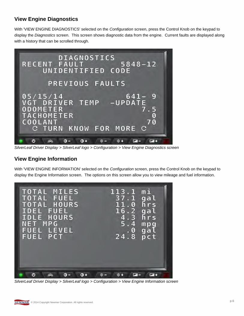
View Engine Diagnostics
With 'VIEW ENGINE DIAGNOSTICS' selected on the Configuration screen, press the Control Knob on the keypad todisplay the Diagnostics screen. This screen shows diagnostic data from the engine. Current faults are displayed alongwith a history that can be scrolled through.
SilverLeaf Driver Display > SilverLeaf logo > Configuration > View Engine Diagnostics screen
View Engine Information
With 'VIEW ENGINE INFORMATION' selected on the Configuration screen, press the Control Knob on the keypad todisplay the Engine Information screen. The options on this screen allow you to view mileage and fuel information.
SilverLeaf Driver Display > SilverLeaf logo > Configuration > View Engine Information screen
© 2014 Copyright Newmar Corporation. All rights reserved. p.6
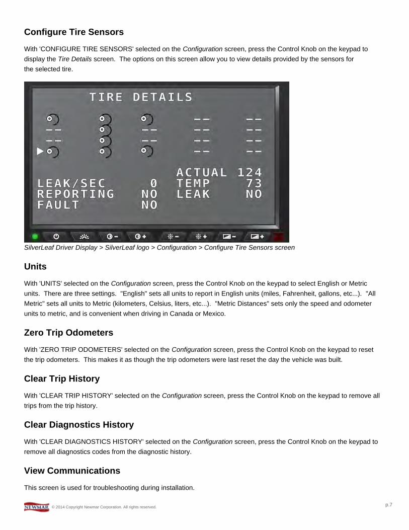
Configure Tire Sensors
With 'CONFIGURE TIRE SENSORS' selected on the Configuration screen, press the Control Knob on the keypad todisplay the Tire Details screen. The options on this screen allow you to view details provided by the sensors forthe selected tire.
SilverLeaf Driver Display > SilverLeaf logo > Configuration > Configure Tire Sensors screen
Units
With 'UNITS' selected on the Configuration screen, press the Control Knob on the keypad to select English or Metricunits. There are three settings. "English" sets all units to report in English units (miles, Fahrenheit, gallons, etc...). "AllMetric" sets all units to Metric (kilometers, Celsius, liters, etc...). "Metric Distances" sets only the speed and odometerunits to metric, and is convenient when driving in Canada or Mexico.
Zero Trip Odometers
With 'ZERO TRIP ODOMETERS' selected on the Configuration screen, press the Control Knob on the keypad to resetthe trip odometers. This makes it as though the trip odometers were last reset the day the vehicle was built.
Clear Trip History
With 'CLEAR TRIP HISTORY' selected on the Configuration screen, press the Control Knob on the keypad to remove alltrips from the trip history.
Clear Diagnostics History
With 'CLEAR DIAGNOSTICS HISTORY' selected on the Configuration screen, press the Control Knob on the keypad toremove all diagnostics codes from the diagnostic history.
View Communications
This screen is used for troubleshooting during installation.
© 2014 Copyright Newmar Corporation. All rights reserved. p.7
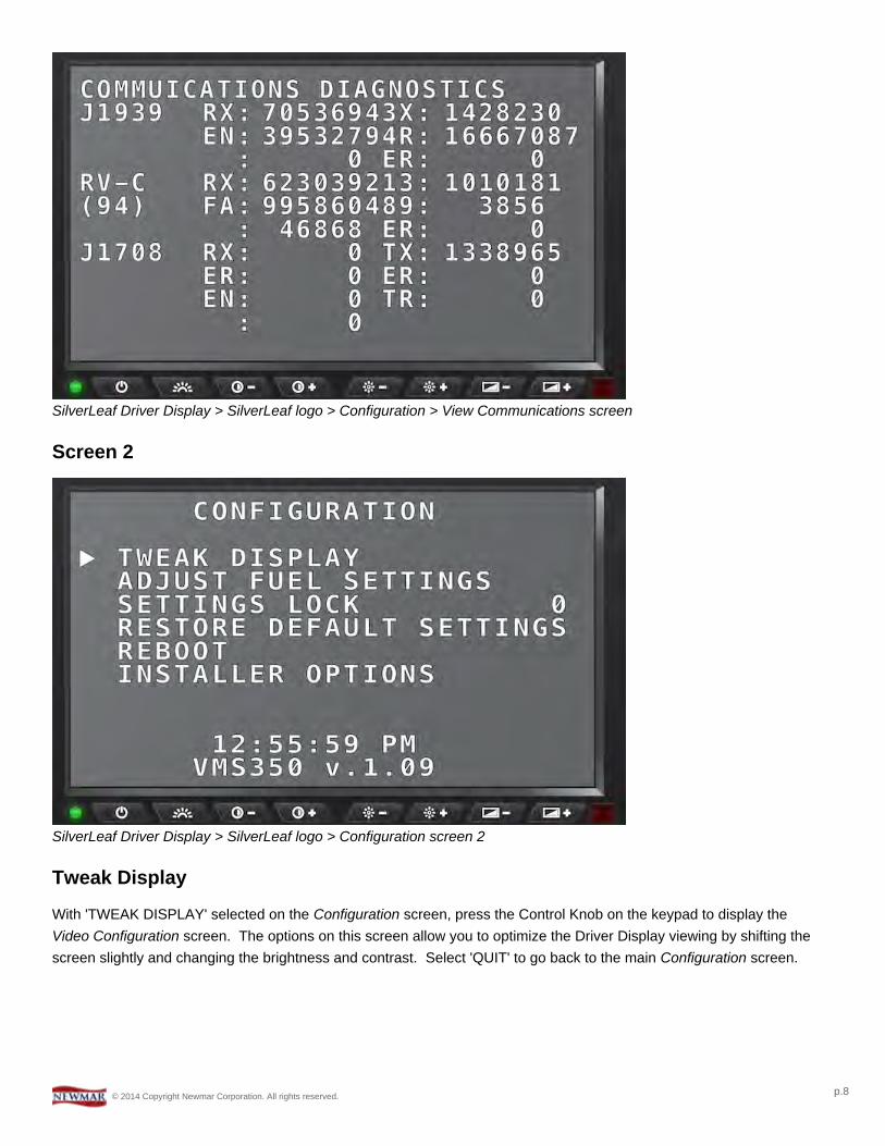
SilverLeaf Driver Display > SilverLeaf logo > Configuration > View Communications screen
Screen 2
SilverLeaf Driver Display > SilverLeaf logo > Configuration screen 2
Tweak Display
With 'TWEAK DISPLAY' selected on the Configuration screen, press the Control Knob on the keypad to display theVideo Configuration screen. The options on this screen allow you to optimize the Driver Display viewing by shifting thescreen slightly and changing the brightness and contrast. Select 'QUIT' to go back to the main Configuration screen.
© 2014 Copyright Newmar Corporation. All rights reserved. p.8

SilverLeaf Driver Display > SilverLeaf logo > Configuration > Tweak Display screen
Adjust Fuel Settings
With 'ADJUST FUEL SETTINGS' selected on the Configuration screen, press the Control Knob on the keypad to displaythe Fuel Configuration screen. The options on this screen allow you to fine tune or 'skew' the fuel readings toadjust how MPG is factored or to build in a 'reserve' fuel buffer.
SilverLeaf Driver Display > SilverLeaf logo > Configuration > Adjust Fuel Settings screen
Settings Lock
When pushing the knob, this allows you to enter a number code. The correct code will then allow you to access theInstaller Option to change settings that were set up at the Newmar factory.
© 2014 Copyright Newmar Corporation. All rights reserved. p.9

This screen is password protected to allow Qualified Service Technicians access to make changes to thecontrol settings. Changing these control settings to improper values can adversely affect the operation of thecontrol system and may cause damage to the coach.
Restore Default Settings
With 'RESTORE DEFAULT SETTINGS' selected on the Configuration screen, press the Control Knob on the keypadto return the unit to its factor defaults.
Never reset any of the system components to factory defaults. The modules should be programmed correctlyby the manufacturer. Resetting any of the SilverLeaf components may cause physical damage to varioussystems on the coach, which could, in turn, cause physical injury.
When in doubt, contact your Service Representative. They can guide you through the best solution for troubleshooting,and, if necessary, replacing the modules at a Newmar Certified Service Center.
Reboot
With 'REBOOT' selected on the Configuration screen, press the Control Knob on the keypad to restart the DriverDisplay.
Installer Options
This option is for installers. With 'INSTALLER OPTIONS' selected on the Configuration screen, press the Control Knobon the keypad to access certain advanced options, which are usually only needed during installation.
This screen is password protected to allow Qualified Service Technicians access to make changes to thecontrol settings. Changing these control settings to improper values can adversely affect the operation of thecontrol system and may cause damage to the coach.
© 2014 Copyright Newmar Corporation. All rights reserved. p.10

HOUSE :: TanksOverviewThis option displays the status of the water tanks and provides access to the Water System Controls.
House Screen - TanksPress the 'House' button on the control keypad to show the House screen and display the Tanks information.
Tanks InformationThis selection displays the Pump and Hookup statuses, as well as the fill levels for the Fresh, Gray, and Black tanks.The tank values are shown as a percentage.
SilverLeaf Driver Display > House button > Tanks information
Water System ControlsWith 'TANKS' selected on the House screen, press the Control Knob on the keypad to display the Water SystemControls screen. This screen allows you to turn the Water Pump ON/OFF and turn the Autofill feature ON/OFF. Turnthe Control Knob to scroll through the options and press the Control Knob to change the selected setting. Select 'QUIT'to go back to the main House screen.
© 2014 Copyright Newmar Corporation. All rights reserved. p.11

SilverLeaf Driver Display > House button > Tanks > Water System Controls
© 2014 Copyright Newmar Corporation. All rights reserved. p.12
HOUSE :: GensetOverviewThis option displays status and settings for controlling various generator-related functions.
House Screen - GensetPress the 'House' button on the control keypad to show the House screen and display the Genset information.
Genset InformationThis selection displays the Genset status, RPMs, temperature, hour meter, and AGS [Auto Gen Start] Lock status.
SilverLeaf Driver Display > House button > Genset information
Generator - 1st screenWith 'GENSET' selected on the House screen, press the Control Knob on the keypad to display the Generator screen.The options on this screen allow you to change the value for:
• Genset Status• Auto Gen Start Lock• Generator Running Mode• Exerciser status• Zones 1 & 2 Auto Gen Start
Turn the Control Knob to scroll through the options and press the Control Knob to change the selected setting. Scroll allthe way to the bottom of the options and select 'QUIT' to go back to the main House screen.
© 2014 Copyright Newmar Corporation. All rights reserved. p.13
SilverLeaf Driver Display > House button > Genset > Generator options 1
Generator - 2nd screenWith 'GENSET' selected on the House screen, press the Control Knob on the keypad to display the Generator screen.Turn the Control Knob to scroll down the screen past the first set of options. The options on this screen allow you to
change the value for:
• Zone 4 Auto Gen Start• Quiet Time Begin & End• Auto Charger start voltage• Topoff Voltage, Run Tim, and Status• Chassis Charger Status
Turn the Control Knob to scroll through the options and press the Control Knob to change the selected setting. Scroll allthe way to the bottom of the options and select 'QUIT' to go back to the main House screen.
© 2014 Copyright Newmar Corporation. All rights reserved. p.14
SilverLeaf Driver Display > House button > Genset > Generator options 2
Generator - 3rd screenWith 'GENSET' selected on the House screen, press the Control Knob on the keypad to display the Generator screen.Turn the Control Knob to scroll down the screen past the first and second sets of options. The options on this screen
allow you to change the value for:
• Chassis Voltage• Exerciser Start Time• Exerciser duration in minutes• The day(s) of the week to run the Exerciser
Turn the Control Knob to scroll through the options and press the Control Knob to change the selected setting. Scroll allthe way to the bottom of the options and select 'QUIT' to go back to the main House screen.
© 2014 Copyright Newmar Corporation. All rights reserved. p.15
SilverLeaf Driver Display > House button > Genset > Generator options 3
Generator - 4th screenWith 'GENSET' selected on the House screen, press the Control Knob on the keypad to display the Generator screen.Turn the Control Knob to scroll down the screen past the first, second, and third sets of options. The options on this
screen allow you to change the value for:
• Maximum Generator Run Time in minutes• Generator Type• Precrank Seconds• Maxcrank Seconds• Stop Seconds
Turn the Control Knob to scroll through the options and press the Control Knob to change the selected setting. Scroll allthe way to the bottom of the options and select 'QUIT' to go back to the main House screen.
SilverLeaf Driver Display > House button > Genset > Generator options 4
© 2014 Copyright Newmar Corporation. All rights reserved. p.16
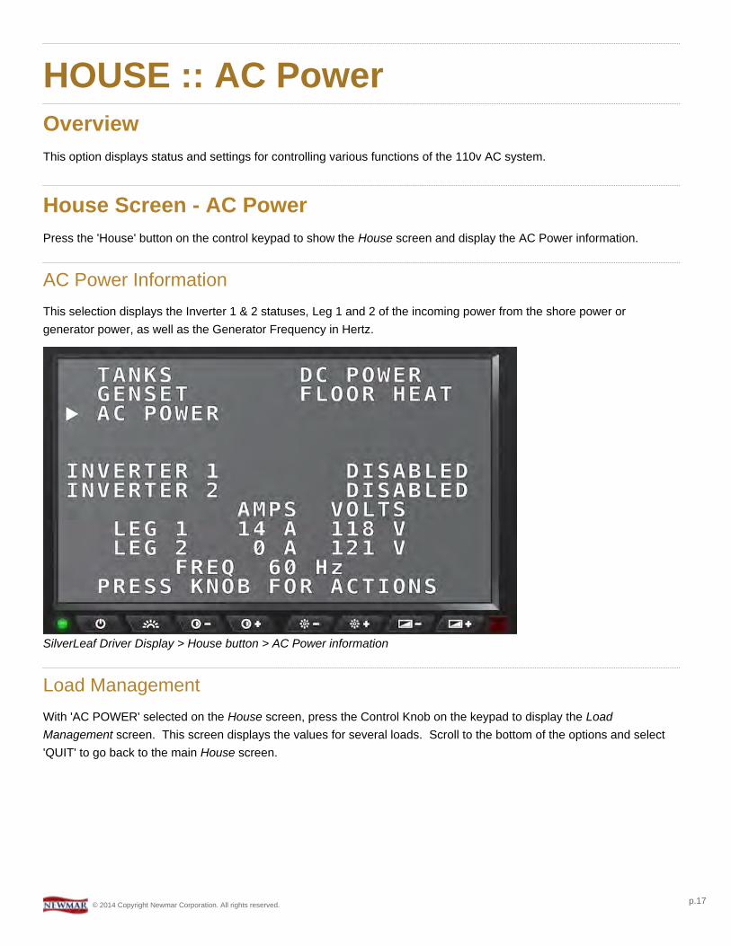
HOUSE :: AC PowerOverviewThis option displays status and settings for controlling various functions of the 110v AC system.
House Screen - AC PowerPress the 'House' button on the control keypad to show the House screen and display the AC Power information.
AC Power InformationThis selection displays the Inverter 1 & 2 statuses, Leg 1 and 2 of the incoming power from the shore power orgenerator power, as well as the Generator Frequency in Hertz.
SilverLeaf Driver Display > House button > AC Power information
Load ManagementWith 'AC POWER' selected on the House screen, press the Control Knob on the keypad to display the LoadManagement screen. This screen displays the values for several loads. Scroll to the bottom of the options and select'QUIT' to go back to the main House screen.
© 2014 Copyright Newmar Corporation. All rights reserved. p.17
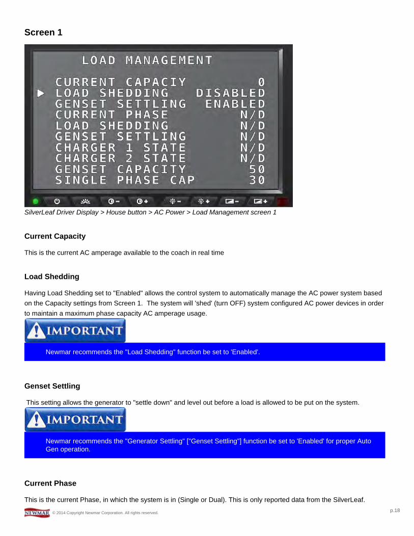
Screen 1
SilverLeaf Driver Display > House button > AC Power > Load Management screen 1
Current Capacity
This is the current AC amperage available to the coach in real time
Load Shedding
Having Load Shedding set to "Enabled" allows the control system to automatically manage the AC power system basedon the Capacity settings from Screen 1. The system will 'shed' (turn OFF) system configured AC power devices in orderto maintain a maximum phase capacity AC amperage usage.
Newmar recommends the "Load Shedding" function be set to 'Enabled'.
Genset Settling
This setting allows the generator to "settle down" and level out before a load is allowed to be put on the system.
Newmar recommends the "Generator Settling" ["Genset Settling"] function be set to 'Enabled' for proper AutoGen operation.
Current Phase
This is the current Phase, in which the system is in (Single or Dual). This is only reported data from the SilverLeaf.
© 2014 Copyright Newmar Corporation. All rights reserved. p.18

Load Shedding
This is reported data from the SilverLeaf indicating if Load Shedding is active or not.
Genset Settling
This is reported data from the SilverLeaf indicating if Genset Settling is active.
Charger 1 State
This tells the current State of Charge for the #1 battery charger.
Charger 2 State
This tells the current State of Charge for the #2 battery charger.
Genset Capacity
This setting specifies the maximum available amperage the Generator can output.
Newmar recommends the "Capacity - Generator" ["Genset Capacity"] function be set to '40 Amps' in coachesequipped with a 10,000 watt generator -- Mountain Aire and London Aire.
Newmar recommends the "Capacity - Generator" ["Genset Capacity"] function be set to '50 Amps' in coachesequipped with a 12,500 watt generator -- Essex and King Aire.
Single Phase Cap
This sets the Load Shedding Amperage value for the Single Phase selection.
Newmar recommends the value for "Single Phase Cap" should be set to '30 Amps' or less.
© 2014 Copyright Newmar Corporation. All rights reserved. p.19
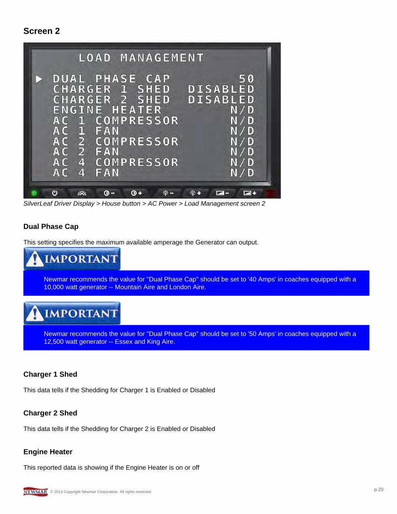
Screen 2
SilverLeaf Driver Display > House button > AC Power > Load Management screen 2
Dual Phase Cap
This setting specifies the maximum available amperage the Generator can output.
Newmar recommends the value for "Dual Phase Cap" should be set to '40 Amps' in coaches equipped with a10,000 watt generator -- Mountain Aire and London Aire.
Newmar recommends the value for "Dual Phase Cap" should be set to '50 Amps' in coaches equipped with a12,500 watt generator -- Essex and King Aire.
Charger 1 Shed
This data tells if the Shedding for Charger 1 is Enabled or Disabled
Charger 2 Shed
This data tells if the Shedding for Charger 2 is Enabled or Disabled
Engine Heater
This reported data is showing if the Engine Heater is on or off
© 2014 Copyright Newmar Corporation. All rights reserved. p.20
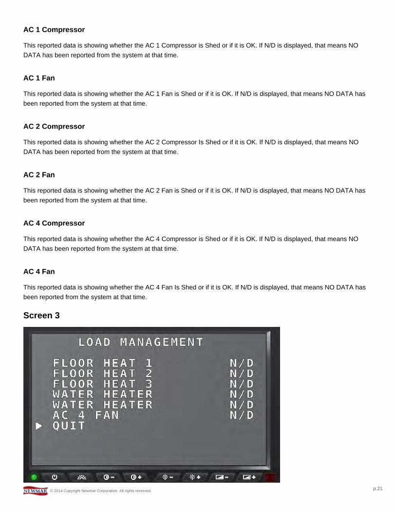
AC 1 Compressor
This reported data is showing whether the AC 1 Compressor is Shed or if it is OK. If N/D is displayed, that means NODATA has been reported from the system at that time.
AC 1 Fan
This reported data is showing whether the AC 1 Fan is Shed or if it is OK. If N/D is displayed, that means NO DATA hasbeen reported from the system at that time.
AC 2 Compressor
This reported data is showing whether the AC 2 Compressor Is Shed or if it is OK. If N/D is displayed, that means NODATA has been reported from the system at that time.
AC 2 Fan
This reported data is showing whether the AC 2 Fan is Shed or if it is OK. If N/D is displayed, that means NO DATA hasbeen reported from the system at that time.
AC 4 Compressor
This reported data is showing whether the AC 4 Compressor is Shed or if it is OK. If N/D is displayed, that means NODATA has been reported from the system at that time.
AC 4 Fan
This reported data is showing whether the AC 4 Fan Is Shed or if it is OK. If N/D is displayed, that means NO DATA hasbeen reported from the system at that time.
Screen 3
© 2014 Copyright Newmar Corporation. All rights reserved. p.21

SilverLeaf Driver Display > House button > AC Power > Load Management screen 3
Floor Heat 1
This reported data is showing whether the Floor Heat 1 is Shed or if it is OK. If N/D is displayed, that means NO DATAhas been reported from the system at that time.
Floor Heat 2
This reported data is showing whether the Floor Heat 2 is Shed or if it is OK. If N/D is displayed, that means NO DATAhas been reported from the system at that time.
Floor Heat 3
This reported data is showing whether the Floor Heat 3 is Shed or if it is OK. If N/D is displayed, that means NO DATAhas been reported from the system at that time.
Water Heater 1
This reported data is showing whether the First Water Heater AC Heating Element is Shed or if it is OK. If N/D isdisplayed, that means NO DATA has been reported from the system at that time.
Water Heater 2
This reported data is showing whether the Second Water Heater AC Heating Element is Shed or if it is OK. If N/D isdisplayed, that means NO DATA has been reported from the system at that time.
Quit
This will take the user back to the AC Power Information Screen.
© 2014 Copyright Newmar Corporation. All rights reserved. p.22
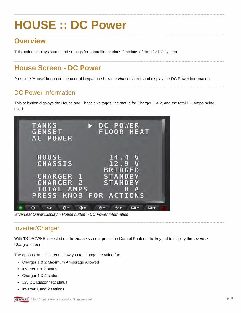
HOUSE :: DC PowerOverviewThis option displays status and settings for controlling various functions of the 12v DC system.
House Screen - DC PowerPress the 'House' button on the control keypad to show the House screen and display the DC Power information.
DC Power InformationThis selection displays the House and Chassis voltages, the status for Charger 1 & 2, and the total DC Amps beingused.
SilverLeaf Driver Display > House button > DC Power information
Inverter/ChargerWith 'DC POWER' selected on the House screen, press the Control Knob on the keypad to display the Inverter/Charger screen.
The options on this screen allow you to change the value for:
• Charger 1 & 2 Maximum Amperage Allowed• Inverter 1 & 2 status• Charger 1 & 2 status• 12v DC Disconnect status• Inverter 1 and 2 settings
© 2014 Copyright Newmar Corporation. All rights reserved. p.23

Turn the Control Knob to scroll through the options and press the Control Knob to change the selected setting. Scroll allthe way to the bottom of the options and select 'QUIT' to go back to the main House screen.
SilverLeaf Driver Display > House button > DC Power > Inverter/Charger screen
© 2014 Copyright Newmar Corporation. All rights reserved. p.24

HOUSE :: Floor HeatOverviewThis option displays status and settings for controlling the Floor Heat system in coaches equipped with the Floor Heatoption.
House Screen - Floor HeatPress the 'House' button on the control keypad to show the House screen and display the Floor Heat information.
Floor Heat InformationThis selection displays the status of the Front, Mid-coach, and Rear heat mats.
SilverLeaf Driver Display > House button > Floor Heat information
Floor Heat Settings - 1st screenWith 'FLOOR HEAT' selected on the House screen, press the Control Knob on the keypad to display the FloorHeat settings screen.
The options on this screen allow you to change the value for:
• Front, Mid-coach, and Rear statuses• Front, Mid-coach, and Rear Schedule settings• Day Settings• Day Begin & End Times
© 2014 Copyright Newmar Corporation. All rights reserved. p.25

• Night Settings
Turn the Control Knob to scroll through the options and press the Control Knob to change the selected setting. Scroll allthe way to the bottom of the options and select 'QUIT' to go back to the main House screen.
SilverLeaf Driver Display > House button > Floor Heat > Floor Heat settings screen 1
Floor Heat Settings - 2nd screenWith 'FLOOR HEAT' selected on the House screen, press the Control Knob on the keypad to display the FloorHeat settings screen. Turn the Control Knob to scroll through the options and press the Control Knob to change theselected setting. Scroll all the way to the bottom of the options and select 'QUIT' to go back to the main House screen.
SilverLeaf Driver Display > House button > Floor Heat > Floor Heat settings screen 2
© 2014 Copyright Newmar Corporation. All rights reserved. p.26
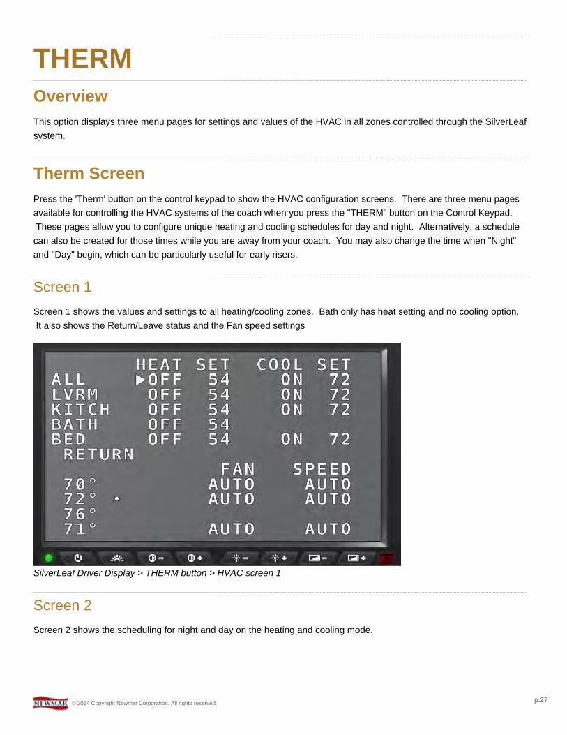
THERMOverviewThis option displays three menu pages for settings and values of the HVAC in all zones controlled through the SilverLeafsystem.
Therm ScreenPress the 'Therm' button on the control keypad to show the HVAC configuration screens. There are three menu pagesavailable for controlling the HVAC systems of the coach when you press the "THERM" button on the Control Keypad.These pages allow you to configure unique heating and cooling schedules for day and night. Alternatively, a schedule
can also be created for those times while you are away from your coach. You may also change the time when "Night"and "Day" begin, which can be particularly useful for early risers.
Screen 1Screen 1 shows the values and settings to all heating/cooling zones. Bath only has heat setting and no cooling option.It also shows the Return/Leave status and the Fan speed settings
SilverLeaf Driver Display > THERM button > HVAC screen 1
Screen 2Screen 2 shows the scheduling for night and day on the heating and cooling mode.
© 2014 Copyright Newmar Corporation. All rights reserved. p.27

SilverLeaf Driver Display > THERM button > HVAC screen 2
Screen 3Screen 3 shows whether the scheduling is Enabled or Disabled. This is also where you would set the value for when daybegins and when night begins.
SilverLeaf Driver Display > THERM button > HVAC screen 3
© 2014 Copyright Newmar Corporation. All rights reserved. p.28
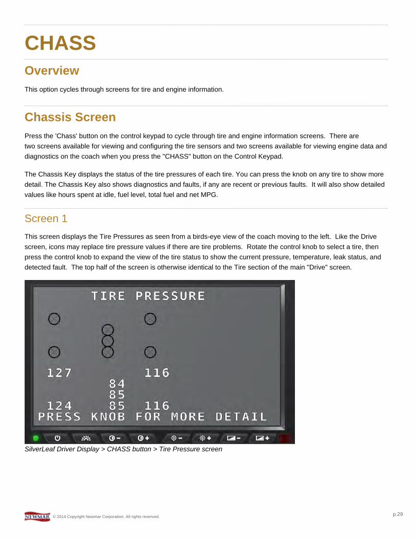
CHASSOverviewThis option cycles through screens for tire and engine information.
Chassis ScreenPress the 'Chass' button on the control keypad to cycle through tire and engine information screens. There aretwo screens available for viewing and configuring the tire sensors and two screens available for viewing engine data anddiagnostics on the coach when you press the "CHASS" button on the Control Keypad.
The Chassis Key displays the status of the tire pressures of each tire. You can press the knob on any tire to show moredetail. The Chassis Key also shows diagnostics and faults, if any are recent or previous faults. It will also show detailedvalues like hours spent at idle, fuel level, total fuel and net MPG.
Screen 1This screen displays the Tire Pressures as seen from a birds-eye view of the coach moving to the left. Like the Drivescreen, icons may replace tire pressure values if there are tire problems. Rotate the control knob to select a tire, thenpress the control knob to expand the view of the tire status to show the current pressure, temperature, leak status, anddetected fault. The top half of the screen is otherwise identical to the Tire section of the main "Drive" screen.
SilverLeaf Driver Display > CHASS button > Tire Pressure screen
© 2014 Copyright Newmar Corporation. All rights reserved. p.29
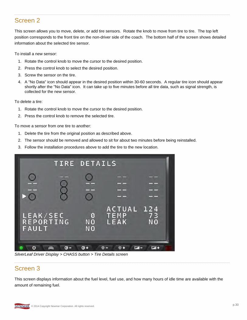
Screen 2This screen allows you to move, delete, or add tire sensors. Rotate the knob to move from tire to tire. The top leftposition corresponds to the front tire on the non-driver side of the coach. The bottom half of the screen shows detailedinformation about the selected tire sensor.
To install a new sensor:
1. Rotate the control knob to move the cursor to the desired position.2. Press the control knob to select the desired position.3. Screw the sensor on the tire.4. A "No Data" icon should appear in the desired position within 30-60 seconds. A regular tire icon should appear
shortly after the "No Data" icon. It can take up to five minutes before all tire data, such as signal strength, iscollected for the new sensor.
To delete a tire:
1. Rotate the control knob to move the cursor to the desired position.2. Press the control knob to remove the selected tire.
To move a sensor from one tire to another:
1. Delete the tire from the original position as described above.2. The sensor should be removed and allowed to sit for about two minutes before being reinstalled.3. Follow the installation procedures above to add the tire to the new location.
SilverLeaf Driver Display > CHASS button > Tire Details screen
Screen 3This screen displays information about the fuel level, fuel use, and how many hours of idle time are available with theamount of remaining fuel.
© 2014 Copyright Newmar Corporation. All rights reserved. p.30
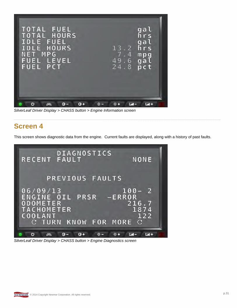
SilverLeaf Driver Display > CHASS button > Engine Information screen
Screen 4This screen shows diagnostic data from the engine. Current faults are displayed, along with a history of past faults.
SilverLeaf Driver Display > CHASS button > Engine Diagnostics screen
© 2014 Copyright Newmar Corporation. All rights reserved. p.31
TRIPOverviewThis option displays information about your past and current trips.
Trip ScreenThe Driver Display tracks two trips simultaneously. One might use the main trip to track mileage and fuel each time theyleave home. The "auxiliary" trip keeps a cumulative total for the season or a year and can be reset at each refueling.
SilverLeaf Driver Display > TRIP button > Trip History screen
Miles To Go
With 'MILES TO GO' selected on the Trip screen, press the Control Knob on the keypad to select this option. Rotate theknob to set the value, then the Driver Display will count down the miles while driving and provide a continuing estimateof the "Time of Arrival" and the amount of "Fuel Required". These estimates will be based on the speed and fuelconsumption averages for the 'Main Trip'.
By entering the distance to your destination from a GPS or map, for example, a good estimate of the "Arrival Time" and"Fuel Required" can be known. This can help plan and manage stops. The "Arrival Time" can also be watched whileadjusting the "Miles To Go" to get the best travel distance on the next leg of your journey.
Reset Main Trip
With 'RESET MAIN TRIP' selected on the Trip screen, press the Control Knob on the keypad to clear the odometer andreadings for this section. Once cleared, however, this action cannot be undone.
© 2014 Copyright Newmar Corporation. All rights reserved. p.32
Reset Aux Trip
With 'RESET MAIN TRIP' selected on the Trip screen, press the Control Knob on the keypad to clear the odometer andreadings for this section. Once cleared, however, this action cannot be undone.
Trip History
With 'VIEW HISTORY' selected on the Trip screen, press the Control Knob on the keypad to display the TripHistory screen.
This screen displays information about past trips. Whenever the 'Main Trip' odometer is reset from the Trip screen, thedata is recorded in the Trip History. The Driver Display can store up to 64 trips in its history. Rotate the Control Knob toscroll through more entries.
SilverLeaf Driver Display > TRIP button > Trip History screen
Splash ScreenPress the "TRIP" button on the control keypad to display the SilverLeaf Splash screen with the system date and time.
© 2014 Copyright Newmar Corporation. All rights reserved. p.33
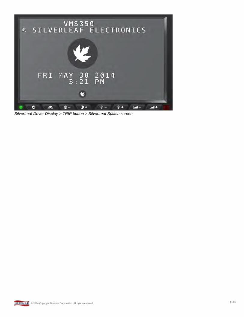
SilverLeaf Driver Display > TRIP button > SilverLeaf Splash screen
© 2014 Copyright Newmar Corporation. All rights reserved. p.34