Embed Size (px)
Citation preview

Welcome! Texas Instruments New Product Update
• This webinar will be recorded and available at www.ti.com/npu
• Phone lines will be muted
• Please post questions in the chat or contact your sales person or field
applications engineer
1
New Product Update: Isolated power products for high voltage applications
Jake Boydston
October 7th, 2021
2

Agenda
• Brief overview of high voltage product types for isolated power
• Trade-offs of common architectures in 3-phase inverter systems
• System benefits of newest products
– Fixed-frequency PWMs
– Flyback controllers
– UCC25800-Q1 low cost transformer driver
– UCC14240-Q1 dual output DC/DC module
3

3 = 1 10k+CUSTOMERS
35+YEARS
2+BILLION UNITS
300+PRODUCTS
AC/DC, isolated,
DC/DC, digitalProducts
shipped
Shipping
controllers
10+TOPOLOGIES
Transforming
every watt
Decades of power
4
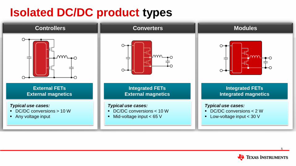
Isolated DC/DC product types
Controllers ModulesConverters
Typical use cases:
▪ DC/DC conversions > 10 W
▪ Any voltage input
Typical use cases:
▪ DC/DC conversions < 10 W
▪ Mid-voltage input < 65 V
Typical use cases:
▪ DC/DC conversions < 2 W
▪ Low-voltage input < 30 V
External FETs
External magnetics
Integrated FETs
External magnetics
Integrated FETs
Integrated magnetics
5

Isolated DC/DC product benefits
Controllers ModulesConverters
Benefits:
▪ Higher power level
▪ Multiple outputs
▪ Multiple topologies
Benefits:
▪ Superior EMC performance
▪ Off-the-shelf transformer options
▪ Low cost solution
Benefits:
▪ Single IC solution
▪ Integrated protections
▪ Highest performance
External FETs
External magnetics
Integrated FETs
External magnetics
Integrated FETs
Integrated magnetics
Most flexibility Highest integration
6

3-phase traction inverter example
V/I
SE
NS
EWired Interface
CAN
12V
Power Management (PMIC)
System
Monitors
Diagnostics
SPI
DC/DC
LDOs
WDT
Non-Isolated DC/DC
Power Supplies
DC/DC High Voltage
Input Power
Protection
Reverse
Polarity
Protection
Digital Processing
CAN
MCU Core
PWM
GPIOs
ADC
Power Stage
Half
Bridge
LS
Driver
L
O
G
I
C
HS
Driver
M
Pos.
Rotor Position
Sensing
Position Sensing
Signal Isolation
D
I
G
I
S
O
Redundant Power Supply
(Backup)
DC/DC DC/DC
Isolated Bias Supply
DC/DC DC/DC
D
I
G
I
S
O
Current and Voltage Sense
ISO
A
M
PAMP
Self-Diagnostics/Monitoring
Sensors (V,T,I %..)
ADC
VREF AFE
Safety & Glue Logic
Loads
Galvanic Isolation
7
IsoGate
Driver
IsoGate
Driver
IsoGate
Driver
IsoGate
Driver
IsoGate
Driver
IsoGate
Driver
400V/800V Battery
Boost/SEPIC
How do you provide power to the
isolated gate drivers in the high
voltage inverter stage?
Inverter power stageTraction inverter

8
Isolated bias architectures comparison
Why choose centralized?
• EMI is not an issue
• Low Fsw, dV/dt (e.g. IGBT)
• Low BOM count
• Lowest total cost
Centralized
Why choose semi-distributed?
• Optimize EMI performance
• Increased Fsw, dV/dt (e.g. SiC, GaN)
• Medium BOM count
• Low cost is still a priority
• Reduce risk of total failure
Semi-distributed
Why choose distributed?
• Optimize EMI performance
• High Fsw, dV/dt (e.g. SiC, GaN)
• Low BOM count
• Power density is a priority
• Lowest risk of total failure
Distributed
Controller / Converter
IsoGate
Driver
IsoGate
Driver
IsoGate
Driver
IsoGate
Driver
IsoGate
Driver
IsoGate
Driver
HV DC Input
1x Transformer4 Windings
Controller / Converter
IsoGate
Driver
IsoGate
Driver
IsoGate
Driver
IsoGate
Driver
IsoGate
Driver
IsoGate
Driver
HV DC Input
Controller / Converter
1x High Side
1x Low Side
Module
IsoGate
Driver
IsoGate
Driver
IsoGate
Driver
IsoGate
Driver
IsoGate
Driver
IsoGate
Driver
Module Module
Module Module Module
HV DC Input

9
Isolated bias architectures comparison
Centralized Semi-distributed Distributed
Controller / Converter
IsoGate
Driver
IsoGate
Driver
IsoGate
Driver
IsoGate
Driver
IsoGate
Driver
IsoGate
Driver
HV DC Input
1x Transformer4 Windings
Controllers
Converters
Modules
Controller / Converter
IsoGate
Driver
IsoGate
Driver
IsoGate
Driver
IsoGate
Driver
IsoGate
Driver
IsoGate
Driver
HV DC Input
Controller / Converter
1x High Side
1x Low Side
Module
IsoGate
Driver
IsoGate
Driver
IsoGate
Driver
IsoGate
Driver
IsoGate
Driver
IsoGate
Driver
Module Module
Module Module Module
HV DC Input
High performance, not cost!

Controllers overviewPWMs & Flybacks
10

Single-ended PWM products
Examples
Typically used for systems <200 W
One PWM controller can be used for all of these topologies!
Buck
(Non-isolated)
Flyback
(Isolated)
Boost
(Non-isolated)
Forward
(Isolated)
Hero productUC2842/3/4/5
TL2842/3/4/5UCC28C40/1/2/3/4/5 UCC2800/1/2/3/4/5
Value
proposition
Lowest cost IC
High gate drive voltage
Highest performance
High efficiency
Most integrated features:
Soft-start, gate clamp, hiccup
Use case Wide range >400-V HV systems <400-V LV systems
11

UCC28C4X/UCC38C4X: reference designs
Topology Reference Design
BuckPMP10783
PMP10833
Boost PMP30653
Flyback
PMP1941
PMP6716
PMP6811
Flybuck PMP10834
SEPIC PMP5353
12
Used for many topologies:
PMP30653: 200-V at 400-mA LED
lighting from a 24-V input• provides a cost effective and precise
constant-current regulation
• open LED protector circuitry
provides overvoltage protection
Visit https://www.ti.com/reference-designs/
before you begin your next design!

Flyback controllers for 65-W applications
13
Quasi resonant (QR)
flyback
Zero voltage
switching (ZVS)
flyback
Active clamp flyback
(ACF)Parameter UCC28600 UCC28781 UCC28782 UNITS
Control
MethodQR ZVS ACF
-
Solution
Standby
Power
210 35 79 mW
Full-load
efficiency
15V@
115VAC
87.1 93.5 94.2 %
Full-load
efficiency
15V@
230VAC
87.9 93.2 93.7 %
Solution
volume274.2 59.4 35.5 cc
Energy
Density0.24 1.08 1.83 W/cc
Efficiency, power density
System cost

Converter overviewUCC25800-Q1
14

UCC25800-Q1Low cost transformer driver with high performance
15
Features Benefits
▪ Operation from 9V to 34V (40V Abs Max)
▪ 6W from 24V input, Up to 10W from 34V input
▪ Integrated half-bridge MOSFETs
▪ Programmable fixed switching frequency up to 1.2MHz
– 1.2MHz default, resistor settable 100kHz – 1MHz
– Frequency accuracy +/-6% maximum over temperature
– External SYNC function
▪ Drive multiple transformers with one UCC25800-Q1
▪ Automatic dead time adjustment with programmable maximum
▪ Integrated soft-start
▪ Disable pin with fault code output
▪ Two-level over current protection
– Programmable via external resistor
– UCC25800A-Q1 is auto retry after over current
– UCC25800L-Q1 is latch after over current
▪ Over Temperature Protection
– 160°C Junction
– 20°C Hysteresis
▪ AEC Q100 Qualified
▪ Low common mode noise due to minimal interwinding
capacitance in transformer
▪ Simple design, highly integrated, no bootstrap capacitor
▪ High switching frequency for smaller size and more robustness
Link to Datasheet Link to EVM Samples Available

UCC25800-Q1: LLC converter EMI benefits
• Open loop controller with secondary side resonance for
tighter regulation
• Lowest Cpri-sec capacitance <2 pF and resonant
switching for extremely low CM noise solution
• High CMTI for fast edge rate switching
Flyback converter LLC converter
UCC21732-Q1
(Isolated gate driver IC)
UCC25800-Q1
16

17
UCC25800-Q1 key advantages + system benefits
Feature Application Impact System Benefit
1.2 MHz FSW +
Open loop control
Small transformer and no
optocoupler
~5% regulation
Higher power density
Lower system cost
Automatic deadtime
controlZero voltage switching
>85% efficiency at 1 MHz
Higher efficiency
Lower system cost
LLC topology with
secondary
resonance
High leakage inductance, low
primary to secondary capacitance
<2-pF primary to secondary capacitance
Lower EMI
Higher CMTI
Adjustable current
limit
Control over the converter’s
current limit
Reliable operation
Lower system cost
Soft-startControlled start up without
excessive currents in power stage
Startup into load or large capacitors
Lower system cost
Sinusoidal currents Simpler to pass CISPR emissions
No snubbers or output inductor
Lower component count
Lower EMI
Enable / fault pin On / Off control and fault reportingFlexible sequencing and system debug
Lower component count
Key advantages
Uninterruptable Power Supply
✓ Split-bobbin transformer for lowest cost
✓ Drive multiple transformers in multilevel
converters with one controller for
lowest cost solution
✓ Integrated protection for long term
reliability
EV onboard chargers
✓ Secondary resonance operation for
higher accuracy over FSW and
component variations.
✓ High frequency operation results in
smaller magnetics and less weight
✓ Drive multiple transformers from one
controller
✓ 1.2MHz switching frequency for small, low
weight transformer and 8mm height
✓ Primary to secondary capacitance of
transformer less than 2pF for mitigating
EMI and extra CMTI
Traction Inverter
✓ Easier to pass CISPR 32 class B EMI
standards with sinusoidal currents and
low transformer capacitance
✓ Cooler system: adaptive dead time
minimizes switching losses in variable
frequency motors
Applications + system benefits
✓ Higher power density
✓ Lowest system cost
✓ Lowest EMI
✓ Highest CMTI
✓ Highest efficiency
✓ Lower component count
UCC25800-Q1
Smaller, lower cost,
lower weight
rransformer
Motor drives
IsoGate
Driver
UCC25800-Q1LLC
24V
24V
+15V
-8V

18
PARAMETER SPECIFICATIONSInput voltage range 6 V – 26 V
Output voltage and current +18 V / -5 V
Switching frequency 2.2 MHz and 500 kHz
Isolation Yes, 2500 VAC (1 sec)
Topology SEPIC + Open loop LLC transformer driver
UCC25800-Q1 EVM measurement data
UCC25800-Q1
LM5156-Q1 Optional components
for 1% load regulation
+18V
-5V
Pass - LLC Board Only with Filter

Module overviewUCC14240-Q1
19

Isolated DC/DC module with integrated transformerTechnology shift for isolated gate driver bias supplies
20
Decades of bulky transformers …
• Bulky – prone to vibrations
• High radiated EMI
• Large footprint & height
• Difficult to design
Flyback
Push-pull
Bulky
XFMR
Isolated power
transfer in
an IC-sized
package
Introducing the
UCC14240-Q1
• 1.5-W high-efficiency isolated
DC/DC power supply
• Industry’s smallest, most
accurate & easiest-to-use
• Proprietary integrated
transformer technology
• No bulky, noisy transformers
2X smaller PCB area, lower BoM
Isolated
Gate Driver
UCC14240-Q1
Isolated
Gate Driver
Push-Pull /
Flyback
7.5-mm height 3.5-mm height
External
2X lower height

UCC14240-Q1 basic isolation3.55mm Height Dual Output Gate Drive Bias w/ Integrated XFMR
21
Features Benefits
▪ Isolated power module with integrated transformer▪ 3.55-mm height,12.8 mm x 10.3 mm with leads (8 mm creepage)▪ 1.5W output power at Ta = 105°C▪ Input voltage range
▪ 24-V nominal▪ 21 V – 27 V, 32 V Abs,max
▪ Dual adjustable output voltages▪ VISO1 to GNDS range 18 V to 25 V▪ VISO2 to GNDS range 2.5 V to VISO1▪ Both < 1.3% accuracy -40°C to 150°C
▪ 3.5pF primary-to-secondary capacitance with low emissions▪ Wide temperature range:
▪ Tj: -40 to 150°C▪ Ta: -40 to 125°C
▪ UVLO, OVLO, PG, soft-start, short-circuit, power-limit, and over temperature protection, CMTI > 150k V/us
▪ 3rd party certified basic isolation ▪ 3k Vrms (60s) ▪ 1.2 kVpk working ▪ 5k-V surge
▪ AEC-Q100 auto grade
▪ Integrated solution enables smaller BOM, reduced board space
and helps with easier system certification
▪ High accuracy to reduce size of IGBTs / SiC switches
▪ Soft start enables minimal overshoot current,
▪ Low EMI, high CMTI, high isolation voltage
Link to Datasheet Link to EVM Order Now

UCC14240-Q1 measurement data
22
(VDD – COM) = +15 V
(VEE – COM) = -5 V
/PG = PowerGood Active Low
Output Current
Soft-
Start

UCC14240-Q1Simple & small BOM and layout
23
EVM top EVM bottom
Flipped
Link to Datasheet Link to EVM Order Now

24
Isolated DC/DC summary
Why choose centralized?
• EMI is not an issue
• Low Fsw, dV/dt (e.g. IGBT)
• Low BOM count
• Lowest total cost
➢ PWMs & flyback controllers
Centralized
Why choose semi-distributed?
• Optimize EMI performance
• Increased Fsw, dV/dt (e.g. SiC, GaN)
• Medium BOM count
• Low cost is still a priority
• Reduce risk of total failure
➢ UCC25800-Q1 converter
Semi-Distributed
Why choose distributed?
• Optimize EMI performance
• High Fsw, dV/dt (e.g. SiC, GaN)
• Low BOM count
• Power density is a priority
• Lowest risk of total failure
➢ UCC14240-Q1 module
Distributed
Module
IsoGate
Driver
IsoGate
Driver
IsoGate
Driver
IsoGate
Driver
IsoGate
Driver
IsoGate
Driver
Module Module
Module Module Module
HV DC Input
Controller / Converter
IsoGate
Driver
IsoGate
Driver
IsoGate
Driver
IsoGate
Driver
IsoGate
Driver
IsoGate
Driver
HV DC Input
1x Transformer4 Windings
Controller / Converter
IsoGate
Driver
IsoGate
Driver
IsoGate
Driver
IsoGate
Driver
IsoGate
Driver
IsoGate
Driver
HV DC Input
Controller / Converter
1x High Side
1x Low Side

25
Visit www.ti.com/npuFor more information on the New Product Update
series, calendar and archived recordings
26

IMPORTANT NOTICE AND DISCLAIMERTI PROVIDES TECHNICAL AND RELIABILITY DATA (INCLUDING DATASHEETS), DESIGN RESOURCES (INCLUDING REFERENCEDESIGNS), APPLICATION OR OTHER DESIGN ADVICE, WEB TOOLS, SAFETY INFORMATION, AND OTHER RESOURCES “AS IS”AND WITH ALL FAULTS, AND DISCLAIMS ALL WARRANTIES, EXPRESS AND IMPLIED, INCLUDING WITHOUT LIMITATION ANYIMPLIED WARRANTIES OF MERCHANTABILITY, FITNESS FOR A PARTICULAR PURPOSE OR NON-INFRINGEMENT OF THIRDPARTY INTELLECTUAL PROPERTY RIGHTS.These resources are intended for skilled developers designing with TI products. You are solely responsible for (1) selecting the appropriateTI products for your application, (2) designing, validating and testing your application, and (3) ensuring your application meets applicablestandards, and any other safety, security, or other requirements. These resources are subject to change without notice. TI grants youpermission to use these resources only for development of an application that uses the TI products described in the resource. Otherreproduction and display of these resources is prohibited. No license is granted to any other TI intellectual property right or to any third partyintellectual property right. TI disclaims responsibility for, and you will fully indemnify TI and its representatives against, any claims, damages,costs, losses, and liabilities arising out of your use of these resources.TI’s products are provided subject to TI’s Terms of Sale (https:www.ti.com/legal/termsofsale.html) or other applicable terms available eitheron ti.com or provided in conjunction with such TI products. TI’s provision of these resources does not expand or otherwise alter TI’sapplicable warranties or warranty disclaimers for TI products.IMPORTANT NOTICE
Mailing Address: Texas Instruments, Post Office Box 655303, Dallas, Texas 75265Copyright © 2021, Texas Instruments Incorporated