Embed Size (px)
Citation preview

Living
Environmental
Systems Division
1
Welcome to our Training Centre
Living
Environmental
Systems Division
2
Green Gateway Initiative
That‟s the equivalent of removing 830,000 cars from the UK‟s roads.
The Stern Report has highlighted the catastrophic danger to businesses of ignoring
climate change and we need to recognise that this is a challenge that involves us all.
If we are to meet this challenge and get anywhere near the targets for emissions
reductions that the Government has set then we need to look at more energy efficient
ways of providing the comfort levels for our buildings that modern life (and increasing
legislation) demands.
Anyone involved in this industry- architects, developers, consultants, building services
specifiers, installers, and equipment manufacturers, needs to find ways to provide
modern, comfortable internal environments, in the most energy efficient and
sustainable way possible.
www.greengatewayinitiative.co.uk
The Green Gateway Initiative is a bold and ambitious 10-point
plan that points the way to a reduction of over 3 million tonnes
of CO2 per year, by 2016.

Living
Environmental
Systems Division
3
Low Carbon Domestic Space
and Water Heating
Design and Installation

Living
Environmental
Systems Division
4
Subjects Covered
• CO2 Reduction Targets
• What is The Ecodan Heat pump
• System Operations
• Design and Application
• Service and Maintenance
• Regulations and Legislation

Living
Environmental
Systems Division
5
CO2 Emission Reduction
• How important is it?
• Energy saving
• Cost savings
• Legal requirement
• Moral obligation

Living
Environmental
Systems Division
6
Domestic CO2 Emissions
• A major cause of climate change comes from the
energy we use to heat, light and run our homes
• The domestic sector is a critical area and is
responsible for 27% of UK CO2 emissions
• Energy demand in the sector grew 17.5% from
1990 to 2003
• All fossil fuels are finite resources and need to be
used as economically as possible.
Source: DTI 2002, DEFRA 2002

Living
Environmental
Systems Division
7
The Code for Sustainable Homes
Minimum standards for energy usage
Current Building Regulations
CO2 emission = Level 0 Target Emissions Rate
Reduction in CO2 from current building regulations (TER)
• Level 1 * -10%
• Level 2 ** -18%
• Level 3 *** -25% by 2010
• Level 4 **** -44% by 2013
• Level 51 ***** -100%
• Level 62 ****** Zero Carbon by 2016
1. Zero emissions in relation to Building Regulations issues (i.e. zero emissions from heating, hot water, ventilation and lighting).
2. A completely zero carbon home (i.e. zero net emissions of carbon dioxide (CO2) from all energy use in the home).

Living
Environmental
Systems Division
8
Fuel Type Kg CO2 per
kWh
Boiler
Efficiency
Kg CO2 per kWh of useful
heat
Coal 0.34 85% 0.40
Oil 0.28 90% 0.31
LPG 0.25 95% 0.26
Gas 0.19 95% 0.20
Electricity 0.43 250% 0.17
Coal Boiler 50 to 85%
Oil Boiler 50 to 90%
LPG Boiler 80 to 95%
Gas Boiler 80 to 95%
Heat Pump 250 to 500%
Typical Efficiencies
Worst case heat pump
vs.
Best case boiler
C02 Emission Levels

Living
Environmental
Systems Division
9
The Ecodan Heat Pump

Living
Environmental
Systems Division
10
The Ecodan Heat Pump!
• What is a Heat Pump?
• Benefits of a Heat Pump
• The Ecodan Packages

Living
Environmental
Systems Division
11
The Heat Pump System
• A heat pump harvests low grade heat energy for free and
delivers it where it is useful
• The heat is upgraded using the vapour compression cycle
• As the main heat source is free, the efficiency is excellent
~300% to 400%
annually

Living
Environmental
Systems Division
12
The Magic of a Heat Pump!
1kWElectrical
power in
2kW
3kW
High temperature
heat output
Low temperature renewable heat energy recovered from the environment
Energy from the ambient air

Living
Environmental
Systems Division
13
Compressor
Condenser
Evaporator
4 way valve
Expansion Valve -
throttling
High pressure high
temp superheated
vapour
Low pressure
superheated vapourLow pressure
saturated liquid
and vapour
Plate Heat Exchanger
The Vapour Compression Cycle: Heating
Condenser

Living
Environmental
Systems Division
14
Benefits of the Ecodan HP
• High CoPs (Coefficients of Performance)
• Reduced Carbon emissions
• Reduced Energy Consumption
• Reduced Running costs
• Electricity can be from Renewable Sources
• No Gas Supply or Fuel Tank needed

Living
Environmental
Systems Division
15
Coefficients of Performance (COP)
Coefficients of performance relate the useful heat output to the electrical energy consumed
COP = Heating output
Power consumed

Living
Environmental
Systems Division
16
Performance Factors
• The unit harvests and “upgrades” free heat energy.
• Therefore the amount of heat delivered is always greater
than the energy paid for.
• COPs in the region of 3.0 to 4.0 are achievable i.e. for every
kW of electrical energy consumed 3.0 to 4.0 kW of heat
energy can be delivered.

Living
Environmental
Systems Division
17
Performance Factors:
COP at varying conditions
• Increase in condensing temperature and decrease in
evaporating temperature reduce COP.
°C
amb
Water temp ºC
Inlet/outlet
30/35 40/45 50/55
-15 1.77 1.41 (1.37)
-7 2.41 1.89 1.46
2 2.97 2.27 1.81
7 3.96 3.05 2.28
20 5.39 3.90 2.87( ) T ambient. - 10°C
*Figures for 8.5 KW heat pump

Living
Environmental
Systems Division
18
Weather Compensation
• The weather compensation works in two ways, primarily
the main function is to reduce the heating circuit flow
temperature as the outside temperature increases.
• This allows the heating to increase to its maximum set
point temperature when the outside temperature reduces
down to -3°C outside.

Living
Environmental
Systems Division
19
Benefits of varying flow temperature
for space heating

Living
Environmental
Systems Division
20
Benefits of varying flow temperature

Living
Environmental
Systems Division
21
Standard House Application Case Study

Living
Environmental
Systems Division
22
Standard House Application Case Study
• House constructed to 2000 building regulations
• Using the existing radiator circuit for the heating
• House temperature 18oC - 21ºC.
• Ambient temperature 2oC
• Flow temperature set point 45ºC
Design conditions

Living
Environmental
Systems Division
23
The Reality of the Heat Pump - Case Study
Heat load vs. Ambient
0.00
1.00
2.00
3.00
4.00
5.00
6.00
7.00
8.00
9.00
-3 -2 -1 0 1 2 3 4 5 6 7 8 9 10 11 12 13 14 15
Ambient Temperature
Heat
load
kW
24hrs0.4%
452hrs 7.6% 2214hrs37%
3326hrs55%
This leaves 2744 hours
above 15°C for
COPs > 4.0 for space heating,
COPs > 3.0 for Hot water heating

Living
Environmental
Systems Division
24
Practical COP – Space Heating
Ambient
Temp
°C
Output
kW
COP Hrs/year Total
output
kWh
Total
input
kWh
-5 to 0 7.1 1.6 24 170 106
0 to 5 4.8 2.1 452 2170 1033
5 to 10 2.1 4.0 2214 4649 1162
10 to 15 .75 4.5 3326 2495 554
Totals 9484 2856

Living
Environmental
Systems Division
25
Practical COP
Output and time weighted COP
COP = 9484
2856
= 3.32

Living
Environmental
Systems Division
26
Run Cost and CO2 Emissions Comparison
Building
Area
(m²)
Heat
Load
(W/m²)
Building
kW
Required
(kW)
Annual
Energy
Demand
(kWh)
Efficiency
(COP)
Annual
CO2
Emissions
(Kg)
Total
Energy
Cost per
year
(£)
HPB 150 50 7.5 17460 3.50 2145 435
Gas 150 50 7.5 17460 0.90 3686 617
Night Cost
p/kWh
Day Cost
p/kWh
HPB 0.044 0.10
Gas 0.0318 0.0318
Based
on:
Percentage saving 42.0% 29.5%
150m2 house
50w/m2 heat loss

Living
Environmental
Systems Division
27
Reduced Annual Running Costs

Living
Environmental
Systems Division
28
Reduced CO2 Emissions

Living
Environmental
Systems Division
29
The Ecodan System

Living
Environmental
Systems Division
30
Ecodan™ Standalone & Packaged System
• The Ecodan heat pump can either be installed as a package or as a standalone system
• Standalone system requires the Mitsubishi Ecodan and the Mitsubishi FTC (Flow temperature controller)
• Packaged system uses 2 separate units: Mitsubishi Ecodan & Hi-Efficiency Hot Water Tank.
• The Mitsubishi unit extracts heat from the outside air and transfers it into the property in the form of „hot‟ water

Living
Environmental
Systems Division
31
1. Ecodan™ 2. FTC

Living
Environmental
Systems Division
32
Ecodan™ Heat pump Systems
The Air to Water Heat Pump is a pre-assembled self contained
unit mounted externally and incorporates:
• All refrigeration equipment assembled, tested and ready for use
• 2 x Pre-insulated 1” BSP water connections (flexible hoses)
• “Boiler Buddy” – standard water filter system.
• Inline flow setter valve

Living
Environmental
Systems Division
33
Technical Introduction to New Product Range
Ecodan - PUHZ –W50VHA – 5KW (A2 W35) heat pump boiler
950mm
74
0m
m
Maximum running Current - 13 Amps
Maximum flow rate – 14.3 L/M
Minimum flow rate – 6.5 L/M
Power supply 16 Amp – 3 core 1.5mm2 cable
Pipe diameter – 22mm
Noise level - 45dba

Living
Environmental
Systems Division
34
Technical Introduction to New Product Range
Ecodan - PUHZ –W85VHA – 8.5KW (A2 W35) heat pump boiler
Maximum running Current - 23 Amps
950mm
95
0m
m
Maximum flow rate – 25 L/M
Minimum flow rate – 10 L/M
Power supply 25 Amp – 3 core 4mm2 cable
Pipe diameter – 22mm
Note - This unit will supersede the
PUHZ-W90VHA
Noise level - 49dba

Living
Environmental
Systems Division
35
Technical Introduction to New Product Range
Zubadan - PUHZ –HW140VHA – 14KW (A2 W35) heat pump boiler
Maximum running Current - 35 Amps
Maximum flow rate – 40 L/M
Minimum flow rate – 20 L/M
Power supply 40 Amp – 3 core 6mm2 cable
Pipe diameter – *28mm
Noise level – 53 dba
1020mm
13
50
mm
*Increase in required pipe external diameter

Living
Environmental
Systems Division
36 Inverter System
• Inverter Driven Variable Speed Compressor
• No Starting Current
• Excellent Temperature Control
• Quiet Operation
• R410A refrigerant
Overview of Ecodan Key Features

Living
Environmental
Systems Division
37
Current
Time
D.O.L. Start
Inverter Start
Reduced Starting current

Living
Environmental
Systems Division
38
Set
Temperature
On/Off Control
Inverter
Control
Improved Temperature Control

Living
Environmental
Systems Division
39
Refrigerants (R410A)
• This system contains R410A which is a blend of 2 HFCs
(HydroFluoroCarbons) R32 and R125.
• R410A is a highly efficient refrigerant compared with it‟s
predecessors
• This is a sealed system that should not leak –
at the end of its life the refrigerant will be recovered and
destroyed

Living
Environmental
Systems Division
40
F-gas Regulations
• Under F-gas regulations anyone handling
refrigerants should have appropriate training
• Not required as the Ecodan™
– All units are hermetically sealed
– All contain less than 6kg of refrigerant
– Installer will not be considered to be handling
refrigerant
• System repair may need a qualified refrigerant
handler
• Analysis of system running parameters will
require an understanding of the vapour
compression cycle

Living
Environmental
Systems Division
41
Pre-charged to 1.5 bar
Un-vented store
expansion vessel
Primary sealed system kit
Inc. 3 bar relief valve
Sized (by the installer) on the total
system volume, (allow 10 litres for
the appliance pipe work)
Set at 0.5 bar
*Not supplied with package* Supplied with package

Living
Environmental
Systems Division
42
Flow setter valve
To aid in the commissioning and fault finding procedure a flow setter valve or
commissioning valve is supplied with each heat pump boiler.
It should be installed in the flow or return pipe-work for the heat pump boiler,
an arrow indicates the direction of flow.
The valve will give an indication of the
actual water flow rate which is being
circulated at a given time.
The flow rate can be adjusted by
altering the resistance screw.

Living
Environmental
Systems Division
43
Packaged System Operation

Living
Environmental
Systems Division
44
• System Operation
• System User Controls
• Operational Features
• Ambient flow temperature adjustment
Packaged System Operation

Living
Environmental
Systems Division
45
Packaged System and User Controls

Living
Environmental
Systems Division
46
Weather Compensation
• CHzone1 max flow temperature 50°C @ -3°C and
below
• CHzone1 min flow OWC applied 30°C @ 15°C and
above
• CHzone1 Temperature ΔT +/ - 5°C
– This stops the system starting and stopping

Living
Environmental
Systems Division
47
The Flow Temperature
Controller Package

Living
Environmental
Systems Division
48
Flow Temperature Controller or FTC
The FTC has been designed so that the Ecodan heat pump can be
incorporated into a conventional heating system.
Key Features
All system components e.g. Time clock, thermostats, pumps can be
either reused in retrofit situations or supplied & installed in a more
conventional manner.

Living
Environmental
Systems Division
49
Flow Temperature Controller or FTC
The FTC Package
Flow Temperature
Controller
PAR-W21MAA
(Remote Controller)
TH1
(Flow Temperature
Sensor)

Living
Environmental
Systems Division
50
Flow temperature Controller
System Application & Operation

Living
Environmental
Systems Division
51
• System Control Chain
• Single System Piping and Wiring Schematics
• Complete System Piping and Wiring Schematics
• Boost Heating Switch Option
• PAR-W21MAA remote controller initial setting
Standalone (FTC) System Operation

Living
Environmental
Systems Division
52
Flow Temperature Controller or FTC
The FTC is controlled and switched like a conventional gas boiler by
240V signals sent by the system components i.e. Time clock,
thermostats, zone valves and pumps.
Ecodan HPFTC
PAR-W21MAA
Remote Controller Target flow
temperature
Operation mode
ON/OFF
System controls (240V)
E.G Stats/Time clock
(End user interface)
A PAR-W21MAA remote controller is supplied with the FTC, this is only used to set the target
flow temperatures at the commissioning stage.

Living
Environmental
Systems Division
53
Single System
Space heating only or Hot water heating only
Complete System (S - Plan)
Both space heating and hot water heating combined
There are 2 ways of interlocking the FTC with heating systems, this
is dependant on how many heating mediums are incorporated into
the installation
Flow Temperature Controller or FTC

Living
Environmental
Systems Division
The “Single system” pipe work schematic
Internal System
Either
radiators/underfloor OR
hot water
Ecodan HP
FTC
TH1 sensor (supplied with FTC) must
be strapped and insulated to the
water FLOW pipe from the Ecodan.
Boiler
Buddy
Flow
setter
From our initial findings two 15-50 pumps
should be installed in series to achieve the
required flow rates stated earlier.
Pumps
At least 150mm pipe work between
pump and setter
Flow Temperature Controller or FTC

Living
Environmental
Systems Division
55
The “Single system” wiring schematic
Ecodan HP
FTC
PAR-W21MAA
remote controller
Time clockThermostat
Pumps
L
N
E3 core
1.5mm
2 core cable
supplied with FTC
To internal
system
230V
50HZ
Honeywell
command centre
(Optional)
Flow Temperature Controller or FTC

Living
Environmental
Systems Division
56
The “Single system” wiring termination schematic
TH1
1 2
Rem. Con.
1 2 S1 S2 S3
Heat pumpFTC
Relay
PCB
S1 S2 S3
Ecodan HP
TH1 Sensor PAR-W21MAA
Remote controller
TB145
Pumps
Time clock
Thermostat
N L
1 2 3 4 5
Site
2 = Heating
3 = Hot water
230V / 50HZ
Flow Temperature Controller or FTC

Living
Environmental
Systems Division
57
The “Complete system” wiring termination schematic
TH1
1 2
Rem. Con.
1 2 S1 S2 S3
Heat pumpFTC
Relay
PCB
S1 S2 S3
Ecodan HP
TH1 Sensor PAR-W21MAA
Remote controller
TB145
1 2 3 4 5
Site
Honeywell command
centre
To system components
Flow Temperature Controller or FTC

Living
Environmental
Systems Division
58
The “Complete system” wiring termination schematic (S-Plan)
Time clock Room
ThermostatPumps Cylinder
Thermostat CH ZV HW ZV
Honeywell
command
centre
HTG
HW
1 2 3 4 5 6 7 8 9 10
L
N
L
N
L N E
1 2
1 2
4 6 2 47 1023 863
52 1 10 82 1 10
1 2 3 4 5FTC TB145
LNEL NN
75852
230V
50HZ
L L
L
Only difference from
Standard S Plan wiring
Flow Temperature Controller or FTC

Living
Environmental
Systems Division
59
Weather compensation & Boost switch
S1 S2 S3
Heat pumpFTC
Relay
PCB
Site
1 2 3
Heating boost switch
(Optional)TH1
1 2
Rem. Con.
1 2
TH1 Sensor PAR-
W21MAA
Remote
controller
Factory fitted loop wire
between terminal 1 & 3
This will provide weather compensated
flow temperature or “Eco Heat” during
heating mode
Flow Temperature Controller or FTC

Living
Environmental
Systems Division
60
Weather compensation & Boost switch
S1 S2 S3
Heat pumpFTC
Relay
PCB
Site
1 2 3
Heating boost switch
(Optional)TH1
1 2
Rem. Con.
1 2
TH1 Sensor PAR-
W21MAA
Remote
controller
The loop wire should be positioned between
terminal 1 & 2 if a constant heating flow
temperature regardless of the ambient
temperature is required.
Flow Temperature Controller or FTC

Living
Environmental
Systems Division
61
Weather compensation & Boost switch
S1 S2 S3
Heat pumpFTC
Relay
PCB
Site
1 2 3
Heating boost switch
(Option)TH1
1 2
Rem. Con.
1 2
TH1 Sensor PAR-
W21MAA
Remote
controller
A standard 2-way switch can be installed to
give the option of boosting the target flow
temperature during higher ambient
temperatures.
*Terminal 1 must be common
Flow Temperature Controller or FTC

Living
Environmental
Systems Division
62
“DIP” switch settings
SW1 SW2 SW3 SW6ON
OFF
1 8 1 8 1 8 1 2
FTCSet tempLiqud Input signal settingInput signal setting
Switches on the FTC control board must be set to the following combinations, this is the factory
default setting but should be checked during the commissioning stage
1 8 1 8 1 8 1 2
Off ON
Flow Temperature Controller or FTC

Living
Environmental
Systems Division
63
PAR-W21MAA remote controller initial setting

Living
Environmental
Systems Division
64
When the power supply is initially switched onto the system the remote
controller will flash “Please wait” in the left hand corner before showing the
language setting screen, this is defaulted to “English” and just needs to be
entered by pressing and holding the BACK button 2 and the
button 4 . for 2 seconds
PAR-W21MAA remote controller initial setting

Living
Environmental
Systems Division
65
The following settings have to be programmed into the controller after the initial
power up at the commissioning stage.
• Setting day & time
• Setting TH1 target flow temperatures
PAR-W21MAA remote controller initial setting

Living
Environmental
Systems Division
66
Setting the day and time
After initial power ON the time and day of the week need to be set
To set the time use the arrows.
The day of the week
can be changed using
the
*Each press advances the day
Sun Mon … Fri Sat
PAR-W21MAA remote controller initial setting

Living
Environmental
Systems Division
67
Setting target flow temperatures
(1) Press the for 3 seconds to activate the initial setting mode.
To set the target flow temperatures for all modes (HEATING/HEATING ECO/HOT WATER)
the following procedure should be followed
PAR-W21MAA remote controller initial setting

Living
Environmental
Systems Division
68
Setting target flow temperatures
Press to switch to the next
parameter setting
* Disregard these settings
PAR-W21MAA remote controller initial setting

Living
Environmental
Systems Division
69
Setting target flow temperatures
Set the target temperature for both “HEATING” and
“HOTWATER” heating with the Temp buttons
PAR-W21MAA remote controller initial setting

Living
Environmental
Systems Division
70
Setting target flow temperatures
4 parameters have to be set for the target temperature in “HEATING ECO” or weather
compensation mode (Target flow temp depends on outdoor temp).
WATER TEMP
HEATING ECO
Display C shows target flow temp
Display D shows outdoor temp
No.1
WATER TEMP
HEATING ECO
Display C shows target flow temp
Display D shows outdoor temp
No.2
Press to switch between C and D - The blinking figure can be changed using Temp
PAR-W21MAA remote controller initial setting

Living
Environmental
Systems Division
71
Factory settings and recommended flow temperatures (Standard application)
Hot water heating
Factory setting – 500C
Recommended setting – 580C
Heating
Factory setting – 400C
Recommended setting – 550C
PAR-W21MAA remote controller initial setting
Living
Environmental
Systems Division
72
Factory settings and recommended flow temperatures (Standard application)
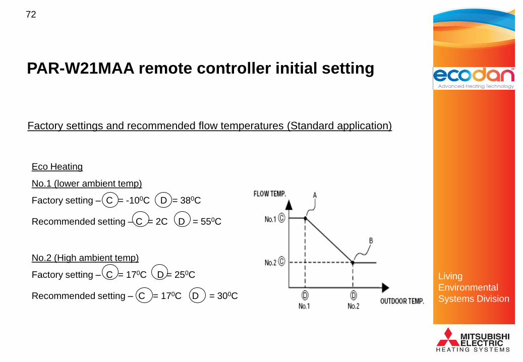
Eco Heating
No.1 (lower ambient temp)
Factory setting – C = -100C D = 380C
Recommended setting – C = 2C D = 550C
No.2 (High ambient temp)
Factory setting – C = 170C D = 250C
Recommended setting – C = 170C D = 300C
PAR-W21MAA remote controller initial setting

Living
Environmental
Systems Division
73
Setting target flow temperatures
To enter the settings and enable the PCB to memorise the settings the
must be pressed.
The ON/OFF button 6 can then be pressed to exit the setup mode.
Once this stage is reached all the ON/OFF and
mode controls will be operated by the time
clock/stats etc, the PAR-W21MAA will only be
useful to monitor the system operation
If required the remote controller can then be
removed from the system and the FTC PCB
will remember the settings.
PAR-W21MAA remote controller initial setting

Living
Environmental
Systems Division
74
• Fault code indication
• System operating parameters
• System operating parameters at the time of error
PAR-W21MAA remote controller Key Features

Living
Environmental
Systems Division
75
Heat Pump System Design

Living
Environmental
Systems Division
76
Heat Pump System Design
• Heat loss calculations
• Radiator / heat emitter sizing
• Domestic hot water storage volume
• Flow rates
• Under floor heating systems

Living
Environmental
Systems Division
77
Heat Loss Calculation
• Mitsubishi Electric do not carry design liability insurance
• General size guidance only
• Design responsibility of specifier to size unit correctly.
• Gledhill Water Storage have design service for larger
projects

Living
Environmental
Systems Division
78
Heat Loss Calculation
• All buildings are suitable for a heat pump!
• Buildings should be well insulated
• Old buildings with solid walls have high heat losses
• Heat loss calculations are required for SAP on new
build properties.
• Mitsubishi BS5449:1990 Heat Loss Calculator
available for retrofit properties
• E-Si performs heat loss calcs for you.

Living
Environmental
Systems Division
79
Building Heat Loss Calculation
Insert
Dimensions
Select figures
from the
Tables sheet
The required
boiler size is
displayed
Complete
information in
yellow shaded
boxes

Living
Environmental
Systems Division
80
Heat Loss Calculation
Available Ecodan heat pump boiler duties
PUHZ-W50VHA (5KW Heating Duty)
PUHZ-W85VHA (8.5KW Heating Duty)
PUHZ-HW140VHA (14KW Heating Duty)

Living
Environmental
Systems Division
81
Heat Loss Calculation
Please note with the W50 and W85 boilers as the ambient temperature
drops the available output also drops they will still provide heat energy at
-150C ambient.
This is not applicable for the 14KW model.

Living
Environmental
Systems Division
82
Radiator Guidance
Insert
Dimensions
Room type
Insert
Dimensions
Room heat
loss is
displayed for
radiator
sizing
Complete
information in
yellow shaded
boxes

Living
Environmental
Systems Division
83
Radiator Guidance
• Heat pumps produce water at 30°C to 60°C
• Ideal for underfloor heating
• Average underfloor heating circuit 35°C
• Fossil fuel boilers heat water to 80°C
• Flow temp in rads design temp approx 70°C or more
recently for condensing boilers 50C.
• Heat pumps can be used with radiators.
• Sometimes larger surface area to emit heat from
lower temp water is required.

Living
Environmental
Systems Division
84
Radiator Sizing
• Due to lower flow temperatures provided by a heat
pump boiler additional care must be taken when
sizing the surface area of a radiator
• As the temperature difference between the primary
and secondary mediums decrease, the heat
exchangers surface area must increase to emit the
same amount of heat energy

Living
Environmental
Systems Division
85
Radiator Sizing Tool
• Available from Mitsubishi
• Allows rad outputs at variable flow temperatures to
be calculated
• Rule of thumb only

Living
Environmental
Systems Division
86
Radiator Sizing Comparison
High flow temperatureLarge ΔT
Radiator
Dimensions and
duties
0.56m² = 1.6KW

Living
Environmental
Systems Division
87
Low flow temperatureSmall ΔT
1.4m² = 1.6KW
Radiator
Dimensions and
duties
Radiator Sizing Comparison

Living
Environmental
Systems Division
88
Retrofit Radiators
• Actual surface area currently designed on appearance
– e.g. under a window, along length of wall
– Radiator under an average window = 1 – 1.5 m2
– Average property likely to significantly oversized
– Perception is small radiator = cold room

Living
Environmental
Systems Division
89
Radiator Sizing Case Study
• 3 bed semi detached house built to 2006 regs
– Heat loss of 5.4kW (20°C/-3°C)
– Design flow temp of 70°C (normal boiler)
– Each bedrooms radiator sizes should only be approx 0.5m² at this
flow temperature
– In reality the installed radiators were on average 1.15m²
– Design flow at 50°C would require radiators to be approx 1.0m²

Living
Environmental
Systems Division
90
DHW hot water usage patterns
Calculations set out in the CIBSE guide should be carried
out to decide the amount of DHW storage required for a
building.
The table below can be used as a rough guide

Living
Environmental
Systems Division
91
Domestic Hot Water Storage Cylinders and FTC
DHW Cylinder Specifications
Indirect type (with coil type heat exchanger)
5KW heat pump – At least 2m2 surface area coil should be used
9KW &14KW – At least 3m2 surface area coil should be used
(Smaller heat exchangers can be used with Ecodan but please be aware that as the area reduces
the performance and storage temperature achievable of the system is reduced)
Copper construction
We will have recommended specifications for stainless steel vessels after further testing
High density injection or spray on foam to current building regulations
Connection point for either strap-on or immersed thermostat

Living
Environmental
Systems Division
92
Domestic Hot Water Storage Cylinders and FTC
Cylinder specification sheet
This sheet can be completed and sent to a cylinder supplier for a quotation

Living
Environmental
Systems Division
93
Cylinder thermostat
Care should be taken when selecting a cylinder thermostat.
If the stat can be set higher than the achievable storage temperature of 550C then
space heating will be held off due to hot water priority.
It is recommended that a thermostat on which the maximum temperature can be
locked is used and is of an electronic type rather than mechanical. This will prevent it
asking for a temperature that cannot be achieved and preventing space heating from
occurring.
A Potterton PTT2 cylinder thermostat is
used on our demonstration system.
This also gives an indication when the set
temp is achieved.
Domestic Hot Water Storage Cylinders and FTC

Living
Environmental
Systems Division
94
The Hot & Cold Supply Flow Rates
• The hot water flow rate achievable from the HP-DEM is directly related to the adequacy of the cold mains serving the property.
• The cold supply must be capable of providing the total simultaneous demand, this should be calculated and could be up to 60 litres/minute in some properties.
• The minimum flow rate recommended for an adequate mains pressure system in any property is 30 litres/minute, this should be checked before the product is applied.

Living
Environmental
Systems Division
95
Under Floor Heating Systems
The BoilerMate contains a pre-fitted pump for the heating
circuit (s). When using an underfloor heating system, if
the manifold does NOT contain a blending valve it should
be of the non-pumped type.
The blending valve should be set at the design
temperature of the underfloor circuit.

Living
Environmental
Systems Division
96
Summary
• Careful consideration must be given to appropriate
application of this technology to maximise its benefits – it
will not suit all properties, especially many retrofits
• Heat emitters may need to be larger
• Remember – lower flow temperatures maximise COP
• Various regulations apply to the design and installation of
such systems

Living
Environmental
Systems Division
97
Application

Living
Environmental
Systems Division
98
Application
• Ecodan location and installation considerations
• Gledhill location, installation and DHW supply
considerations
• Interconnecting pipe work and wiring

Living
Environmental
Systems Division
99
Location Considerations
• Weight
• Space requirement
• Anti Vibration/Noise requirements
• Electrical details
• Drainage

Living
Environmental
Systems Division
100
Space requirements
Space is required around the a heat pump to allow air flow.
Below is the required space for the 8.5KW heat pump, these vary for
other models and can be found in the relevant installation manuals.

Living
Environmental
Systems Division
101
Space requirements
Air outlet grille for each model are available to divert airflow and reduce minimum
dimensions (PAC-SF08SG-E).
(Figures in brackets are for 14KW model)

Living
Environmental
Systems Division
102
Space requirements
• As Ecodan recovers heat from the environment, the
exhaust air from the fan can be uncomfortably cold,
deflectors are available if the units are to be installed in a
pedestrian area e.g. Patio
• Considerations should be made so that the area in front of
the Ecodan is not going to cause to much disruption to
occupants

Living
Environmental
Systems Division
103
Noise / vibration nuisance
• Flexible hoses (2 x 600mm 1” bore steel braided rubber flexible hose, one for flow and one for return, supplied loose with the unit. (Supplied with package)
• Anti- Vibration mountings i.e Tico pad (NOT supplied with package)
Care should be taken to prevent any vibration transfer into buildings
Noise considerations should be taken into account when locating in close
proximities with other residences

Living
Environmental
Systems Division
104
General Ecodan Electrical Installation
• A qualified part P certified Electrician is required to install the power supply
• Care should be taken to ensure the power supply is weather proof
• Supply cable should be either armoured cable, or twin + earth protected in conduit
• Power should be isolated locally within 1.5 metres, minimum 3mm contact gap in isolator
• An RCD (residual current device) should fitted in the supply to the Ecodan this should have a tolerance of 30mA

Living
Environmental
Systems Division
105
Defrost Cycle & Drainage
As the Ecodan extracts heat from the air at low
temperatures the heat exchanger may accumulate a
slight build up of frost/ice.
The unit will detect this and automatically reverse its
cycle sending hot gas (up to 600C) around the coil as
a defrost strategy.
This usually last for less than 4 minutes.

Living
Environmental
Systems Division
106
• When the unit is providing water heating the refrigerant to
air heat exchanger will cool, and therefore condense
moisture from the air.
• This condensate will drain from the unit and provision for its
disposal may be needed i.e gravel pit.
• Up to ~ 8L/hr
Defrost Cycle & Drainage
Living
Environmental
Systems Division
107
Summary and additional
external considerations
• Clearances around unit and provision for condensate disposal
• Noise, visual impact on property and neighbours. e.g. avoid
sitting near windows, anti vibration pads available
• Qualified electrician required to install power supply
• Planning permission
• Scaffolding tower and/or ladder access for installation and
servicing at high level
• Protection from physical damage/vandalism

Living
Environmental
Systems Division
108
Electrical Considerations
• A qualified part P certified Electrician is required to install the power supply
• Power should be isolated locally within 1.5 metres
• 6mm core cable protected by a 32 amp MCB
• All other internal protection is supplied pre-wired in the package

Living
Environmental
Systems Division
109
Interconnecting pipe work and wiring
• Pipe work and insulation
• Visual Impact
• Essential protection requirements
• Wiring

Living
Environmental
Systems Division
110
Interconnecting pipe work and insulation
22mm 28mm
PUHZ-W50VHA
PUHZ-W85VHA
PUHZ-HW140VHA
Required pipe work diameters between outdoor and indoor.
Note – Larger diameter required for 14KW model

Living
Environmental
Systems Division
111
Interconnecting pipe work and insulation
• Gledhill package - interconnecting pipe run must not exceed 60 metres equivalent length (30 metres difference between units) inclusive of height difference.
• Standalone package – flow rates for each heat pump model must be achieved by sizing the circulating pumps to suit the pipe work.
• Provisions should be made to fit AAV‟s or bleed valves at the highest point in the pipe work
• Pipe work MUST be insulated with Armaflex™ or similar insulation (thermal conductivity 0.04W/m.K).
• To ensure minimal thermal heat loss
*(Failure to to insulate the pipe work WILL reduce the efficiency of the system dramatically)
• For weather protection
• To help prevent freezing

Living
Environmental
Systems Division
112
Air locks, evacuation and lack of flow rate
Precautions should be taken to ensure the evacuation of all air from
the entire primary system.
To accomplish this automatic air-vents should be installed at the
highest point of the primary pipe work.
Failure to do so will result in the heat pump boiler displaying one of
the following errors on the Ecodan PCB LED display
7 Segment LED 7 Segment LED
OR
U1 P6
To reset turn the power to the Ecodan OFF & ON. Continuous reset with
failure to rectify the fault will result in damage to the boiler

Living
Environmental
Systems Division
113
Heating System Bypass
Automatic bypass valves will be required in the heating systems if it is proposed to fit
thermostatic radiator valves (TRV‟s) to all radiators or fit zone valves to control all the
separate heating circuits. To meet the requirements of Building Regulations for a boiler
interlock, it is recommended that the radiator in the area where the room thermostat is
installed should be fitted with lock shield valves on both connections

Living
Environmental
Systems Division
114
The Hot & Cold Supplies
Secondary Hot Water CirculationIf the dead leg volume of the
hot water draw-off pipe work
is excessive a secondary hot
water circulation system
could be considered.
*As a rule of thumb if the hot
water delivery time is greater
than 60 seconds
Hot flow & return pipe work must be insulated
SH WHB
WHB
SCV
SINK
BATH
1
2
34
1. Bronze circulator2. Expansion Vessel3. Hot water return pipework4. Single check valve/non return valve - should be fitted
as close as possible to the Accolade 2000 appliance

Living
Environmental
Systems Division
115
Visual Impact Considerations
• Location of Ecodan
• External pipe work
• Minimise external pipe runs
• Trunking
– E.g inaba-denko

Living
Environmental
Systems Division
116
Interconnecting cables
PUHZ-(H)W50/85/140VHA with Flow Temperature Controller
• A 4 core interconnecting cable is required, this is not supplied with the package
• Minimum conductor size 1.5mm²
• Must not exceed 30 Metres in length
• Must be one cable without any joints
Living
Environmental
Systems Division
117
Essential protection requirements
Filters
– The heat exchanger must be protected from particulate
contaminates in the water circuit.
– When retrofitting provision shall be taken to avoid
contaminates blocking the water circuit within the Heat
Pump.
– A Fernox boiler buddy is supplied with the package and
MUST be fitted to the system between the Ecodan and
Boilermate as close to the Ecodan as possible in the flow
line.
* It is not weather proof so should be positioned indoors

Living
Environmental
Systems Division
118
Freezing!
• One of the biggest risk to the system is freezing the water
contained in the plate heat exchanger.
• Heat exchanger has 1mm capillaries
– Therefore vulnerable to ice damage
• A burst heat exchanger will cost £300
• Plus a days labour from a fridge engineer
• Possible compressor damage
• Potential bill of £900+

Living
Environmental
Systems Division
119
• Provision shall be taken to avoid this pipe work
freezing during winter months i.e. antifreeze/inhibitor,
such as:
• Fernox PROTECTOR ALPHI-11™
• Protects against
– corrosion and limescale
– commonly used in heating systems
– Non-toxic, environmentally friendly
– Combined antifreeze and inhibitor
Essential protection requirements
• Should make up 25% of the total volume.
Living
Environmental
Systems Division
120
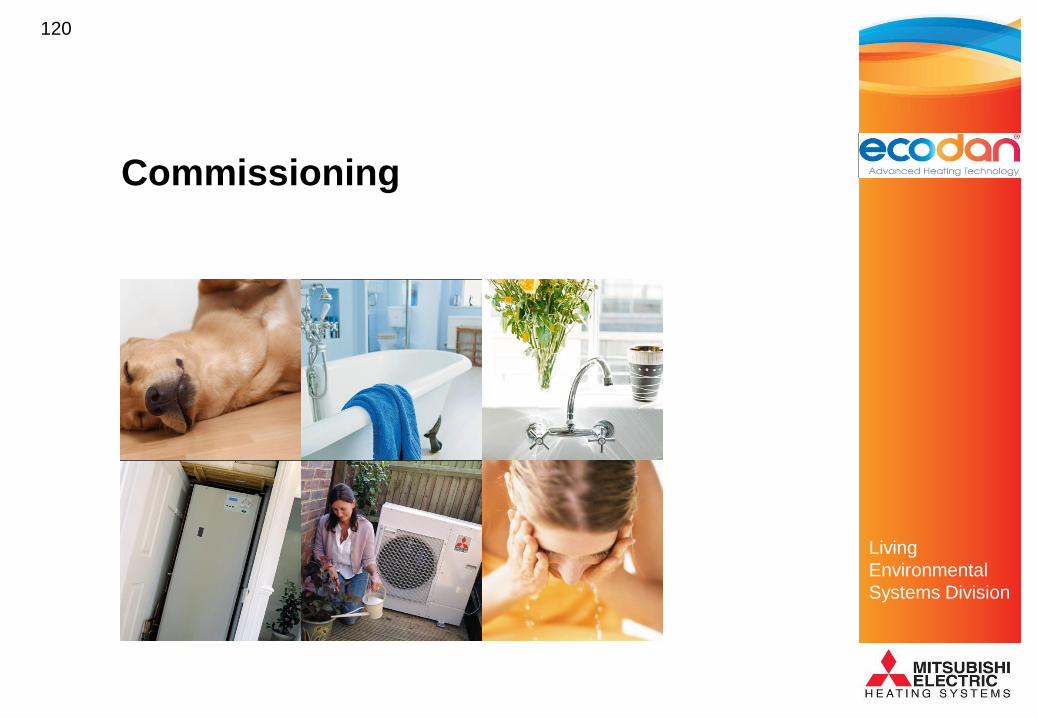
Commissioning

Living
Environmental
Systems Division
121
Commissioning Checklist
• Add Fernox Alphi 11 (anti freeze)
• Check air charge is in expansion vessels
• Pressurise primary circuit to approximately 1.50 Bar
• Open all isolating valves
• Release ALL air from the system using automatic air vents
at the highest points of the system

Living
Environmental
Systems Division
122
Before bleeding the air from the system the zone valves should be manually
opened to prevent air lock and possible damage of the circulating pumps.
Commissioning

Living
Environmental
Systems Division
123
FTC System Commissioning
• Operate the system by selecting constant run for BOTH
channels on the installed two channel time clock
• DHW heating will then take priority and raise the hot water
store until the cylinder thermostat is opened.
• Once this temperature is achieved check that the DHW zone
valve closes and CH valve opens. With the boost switch link
between terminals 1 and 2 the system should then target the
preset temperature selected in heating mode during the “Initial
Setting mode”.

Living
Environmental
Systems Division
124
Commissioning
• Indications should be placed on the system and in the
house instructions to ensure that if for any reason the
heating system is emptied the anti-freeze in the pipe-work is
replaced.

Living
Environmental
Systems Division
125
Service and Maintenance

Living
Environmental
Systems Division
126
Annual Servicing (Boilermate)
Service/maintenance recommendations relating to the
Un-vented store.
• Check that the correct rating and type of fuse is fitted to the electrical supply.
• Check for the presence of supplementary earth bonding.
• Clean out the strainer in the combination valve.
• Check the expansion charge pressure and top up if necessary (1.5 bar).
• Clean flow regulators (restrictors/aerators) as applicable and check for correct flow rate.

Living
Environmental
Systems Division
127
• Low maintenance sealed system
– Like a fridge!
• Refrigeration engineer not required
• Essentially a visual inspection
• Unit needs to be kept clear of debris
• Check for signs of damage to unit
• Heat exchanger to be kept clean
- Calclean environmentally friendly coil cleaner
- Brush to remove debris e.g. leaves
Annual Servicing (Ecodan)

Living
Environmental
Systems Division
128
7 Segment LED
ON
1 2 3 4 5 6
Display Mode
O Off
C Cool
H Heat
d Defrost
Display Comp4-way
valve
Solenoid
valve
Warm
up
0 - -
1 - - ON
2 - ON
3 - ON ON
4 ON -
5 ON - ON
6 ON ON
7 ON ON ON
8 ON
System Monitoring & Diagnosis
LED Display inside Ecodan Unit

Living
Environmental
Systems Division
129
7 Segment LED
ON
1 2 3 4 5 6
Set dip switches to
monitor system
parameters – either
current or pre fault
condition
Please Refer to the Technical
Manual for Settings – Note
settings are not the same as
other Mr. Slim
System Monitoring

Living
Environmental
Systems Division
130
System monitoring – examples
• Water inlet temperature (TH32)
• Ambient temperature (TH7)
• LEV-A & B opening pulses
• Discharge temperature (TH4)
• Discharge superheat
• Compressor running current
Note – All of the above examples can be checked for current or pre fault code values

Living
Environmental
Systems Division
131
Air to Water Ecodan Refrigerant Circuit
1
8
3
2
10
11
4 5
7
6
9Water out
Water in
Plate
H/ex.TH4
TH7TH3
TH6
TH32
HP switch
P-sensor

Living
Environmental
Systems Division
132
Ecodan – Monitoring Parameters
Water out
Water in
Plate
H/ex.TH4
TH7
TH3
TH6
TH32
HP switch
P-sensor

Living
Environmental
Systems Division
133
on
off
4 hours 30 min
30 min
At power on, warm up mode operates 4 hours & stops 30mins
Outdoor temp 21°c or less warm up mode operates 30mins &
stops 30mins
Compressor „buzzes‟
Unit Applies Low frequency, Low current power to the
compressor
Warm up mode

Living
Environmental
Systems Division
134
Regulations and Legislation

Living
Environmental
Systems Division
135
Regulations
• Working at Heights
• Approved Document P: Electrical Safety
• Approved Document E: Resistance to the Passage of Sound
• Approved Document B: Fire Safety
• Approved Document L1A: Conservation of Fuel and Power (New Dwellings)

Living
Environmental
Systems Division
136
Electrical Regulations
• Approved Document P: to cover power supply to
Gledhill Unit
• Approved Document P: to cover power supply to
Mitsubishi Unit
• Wiring Regulations: 17th Edition apply in both
cases

Living
Environmental
Systems Division
137
Approved Document P: Electrical Safety
• Third party certification is not permitted
• The installation and commissioning of external
mains voltage equipment is a controlled service
• The interconnecting wiring is not subject to
approved document P, as it only carries 12v and is
classed as extra low voltage

Living
Environmental
Systems Division
138
Installers must have attained a City & Guilds Certificate
(6084) in Energy Efficiency to commission the unit
What the C&G 6084 course covers:
Why energy consumption affects the environment
How energy efficiency affects the heating installer
Legislation that forces change
The requirements of Approved Doc. L and supporting
documents such as CHeSS
Additional Qualifications
Living
Environmental
Systems Division
139
Approved Document L1A: Conservation
of Fuel and Power (New Dwellings)
• Installations must conform with this document
• The „Domestic Heating Compliance Guide‟ gives further guidance
• The installation of heat producing equipment is a controlled service
• Standard Assessment Procedure (SAP)

Living
Environmental
Systems Division
140
Microgeneration Requirements
• The government has produced a Microgeneration Installation Standard
• This outlines best practice for heat pump installations
• Any Grants and/or tax concessions will be dependant upon adhering to this standard
• Installations need to meet the requirements of the HVCA Guide to Good Practice – Heat Pumps (TR/30)

Living
Environmental
Systems Division
141
Microgeneration Requirements
• Installers must have current accreditation such as:-
– Appropriate NVQ level 3
– Other relevant training e.g. Manufacturer‟s product
training
– Membership of a competent person scheme
– Possession of a relevant Skillcard
– Experience gained through a mentoring process
– Demonstrable track record of successful installation
• The relevance of the above will require independent
verification

Living
Environmental
Systems Division
142
Microgeneration Requirements
• The contractor must understand the design and its application
and explain this to the customer
• This explanation must include the proportion of design heat
loss and design hot water load to be supplied by the heat
pump and an estimate of the annual energy performance
• The following disclaimer must be included:

Living
Environmental
Systems Division
143
Microgeneration Requirements -
Disclaimer
„The performance of Microgeneration heat pump
systems is impossible to predict with certainty due
to the variability of the climate and its subsequent
effect on both heat supply and demand. This
estimate is based upon the best available
information but is given as guidance only and
should not be considered as a guarantee.‟

Living
Environmental
Systems Division
144
The Future of the Heat Pump
• Cleaner electricity generation
– Lower CO2 emissions
– Heat pump advantage grows
– Carbon free generation = carbon free heating
– Low carbon electricity generation is enhanced by
a factor equal to the COP of the heat pump
• Carbon savings from installed heat pumps will improve
as each year passes

Living
Environmental
Systems Division
145
The Future of the Heat Pump
• If CO2 emission reduction is important, the heat
pump has a big future
• The air heating products have been available for
some time
• The water heating products have now arrived
• Advances in technology have now made water
heating a more than viable option

Living
Environmental
Systems Division
146
Thank you
Discussion