Embed Size (px)
Citation preview

Welcome to PHOENIX CONTACT
The highly available Solution
for reliable Process Control:
Ashish Manchanda.
Vice President

Seminar Content – Section 1
2 | Process Fieldbus | Vogt | Interface | 28/Nov/2012
Section 1: Introduction / Differences between fieldbus & Analogue
Section 2: Physical Layer
Section 3: Innovations in Network Design

Traditional
Analog & Discrete Instruments
4-20 mA Systems
Advantages:
OPEN, interoperable, interchangeable
Broad range of equipment
Multiple suppliers
Standard control system interfaces
Standard support equipment
Shortcomings:
Limited information
– one variable, one direction
Point-to-point wiring
I/O
4-20 mA

Smart Instruments
Advantages:
More information
Two-way communication of
multiple variables
Better accuracy, reliability
Faster system commissioning
Easier configuration, calibration
maintenance, and support
Tradeoffs:
Limited interoperability
Lack practical multidrop
capability
Lack control loop performance
Special control system
interfaces
Special support devices
Hybrid Instruments or Intelligent Instruments with Custom Interfaces
Analyzer
Proprietary or Custom
Interface
PLC

HART Communication Protocol
Majority of HART devices in service at HART 5
Foundation Fieldbus advantages
31.25 kbps vs 1.2 kbps
– 30 x faster
Multi-drop capability
FULL bi-directional communications
Deterministic communications
– Enables Control in Field

How Fieldbus is Different from 4-20
Fieldbus devices are connected in parallel on the bus, which
carries digital data from/to all the devices on the bus
Fieldbus devices provide almost unlimited information to all
other devices on the network
Data have cyclical redundancy checking (CRC) to ensure
receiving devices use only good data
A multi-drop fieldbus does not have the shortcoming of point-to-
point wiring
4-20mA
P.S.
fieldbus
P.S.

Fieldbus and 4 – 20 mA
Similarities
Conforms to existing
standard
Twisted pair wiring
Terminal blocks
Similar wiring practices
Provision for intrinsic safety
Support for redundant
power supply
Differences
Foundation Fieldbus is
different from the traditional
system as it
Supports up to 32 parallel
field devices
Requires special power
supply
Requires power
conditioners
Requires network
terminators

Section 2
8 | Process Fieldbus | Vogt | Interface | 28/Nov/2012
Section 1: Introduction / Differences between fieldbus & Analogue
Section 2: Physical Layer
Section 3: Innovations in Network Design

9 | Process Fieldbus – highly available| | Business Development | 2011
fieldbus Power Supply
(optional redundancy)
Junction box /
scalable barriers
Foundation H1
WLAN
DP
PA
FOUNDATION HSE ProfiNet Industrial Ethernet
Inline IO
Process-Connect Technologies
Fieldbus Wireless Inline IO
HART
Multiplexer
Signal
Isolators
Point to point
Point to point

10 | Profibus PA / Foundation Fieldbus |
Physical Layer – Basics – Foundation Fieldbus H1
DCS with
H1-Card
9…32 VDC
0,75… 1,2 Vpp
Transmission speed: 31.25 kBit/s
Manchester code Bus Powered (MBP)
Via twisted-pair cable
Power and Communication in one cable
FF Power
Supply
Power Supply
Physical Layer — The Physical Layer receives messages from the Communications Stack and
converts the messages into physical signals on the fieldbus transmission medium, and vice-versa.

11 | Profibus PA / Foundation Fieldbus |
Physical Layer – Basics – Profibus PA
DCS oder PLC,
DP basierend
9…32 VDC
0,75… 1,2 Vpp
DP/PA
Coupler
or Link
Power Supply
Transmission speed: 31.25 kBit/s
Manchester code Bus Powered (MBP)
Via twisted-pair cable
Power and Communication in one cable
12 | Profibus PA / Foundation Fieldbus |
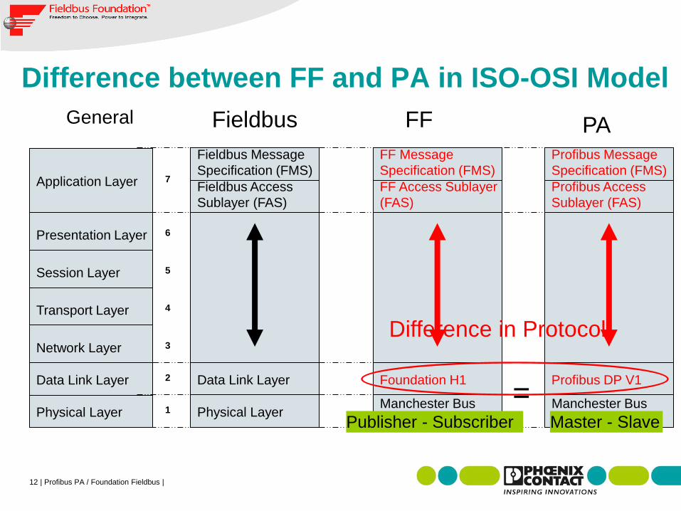
Difference between FF and PA in ISO-OSI Model
General
Physical Layer
Data Link Layer
Network Layer
Transport Layer
Session Layer
Presentation Layer
Application Layer
1
2
3
4
5
6
7
Physical Layer
Data Link Layer
Fieldbus Access
Sublayer (FAS)
Fieldbus Message
Specification (FMS)
Manchester Bus
Powered (MBP)
Foundation H1
FF Access Sublayer
(FAS)
FF Message
Specification (FMS)
Manchester Bus
Powered (MBP)
Profibus DP V1
Profibus Access
Sublayer (FAS)
Profibus Message
Specification (FMS)
Difference in Protocol
Fieldbus FF PA
= Publisher - Subscriber Master - Slave

Data Encoding
Bit Level Encoding
Inserts a time reference on a signal to determine bit
boundaries
Applies Manchester bit encoding method
Data Encoded
1 1 1 0 0 0 1
1 1 1 1 0 0 0 Data
Clock

Max
Segment
Length
1,900 m
(6,232 ft)
1,200 m
(3,936 ft)
400 m
(1,312 ft)
200 m
(656 ft)
Foundation Fieldbus
Cable Type and Description
Type A: Multi or single-twisted-pair,
individually shielded
Type B: Multi-twisted-pair,
with an overall shield
Type C: Multi-twisted-pair,
without a shield
Type D: Multi-core, without twisted
pairs, without a shield
Permitted Fieldbus Cable Types

Fieldbus Terminators
Terminators are required (one at each end)
Match line impedance to minimise reflections and distortions
Maximum of two terminators
T
D
T
100W
1mF
DCS

Terminator
A terminator is placed at the beginning or end of a
segment to avoid reflection
The terminator impedance value is equivalent to an
impedance of 100 Ohm and 1uF.
FF Training

Power Conditioner
Passes DC (power)
Rejects AC (signal)
Bulk Power
Supply
FF Power Conditioner
H1 Fieldbus
9 – 32
Vdc
This image represents the basic
required circuit though all
manufacturers incorporate additional
features

Fieldbus Power Supply Specification
FF-831
Issued March 2004
Manufacturer ‘Self-Certifies” and
submits test results to Fieldbus
Foundation

Typical Field Device Couplers
FF-846 Specification
Passive Device Couplers
– Typically referred to as “Blocks”
Active Device Couplers
– Fieldbus Barriers

Surge Protection for Fieldbus
Fieldbus installations are more vulnerable to surge
damage than conventional ‘point-to-point’ wiring
Surge Protectors are available for:
FISCO (Fieldbus Intrinsically Safe Concept)
Fieldbus Barriers
Trunk (optionally at one or both ends of trunk-
depending on integrity of protection required)
Spurs
Field Devices

Grounding or Earthing
Grounding rules used in the installation of the fieldbus
should follow current standard practices based on
company/plant standards and applicable international
standards
Fieldbus devices should not connect either conductor of
the twisted pair to the ground at any point in the network
Shields shall NOT be used as a power conductor
There may be additional specific requirements for I.S.
installation

22 | Profibus PA / Foundation Fieldbus |
Foundation Fieldbus / Profibus PA
Digital, parallel, plug n play Communication Network
For up to 32 intelligent Field Devices
Current Consuption between 10 and 50 mA each +
-
Max 1900 Meters
Bus-Termination at Beginning and End
Te
rmin
ato
r
Te
rmin
ato
r
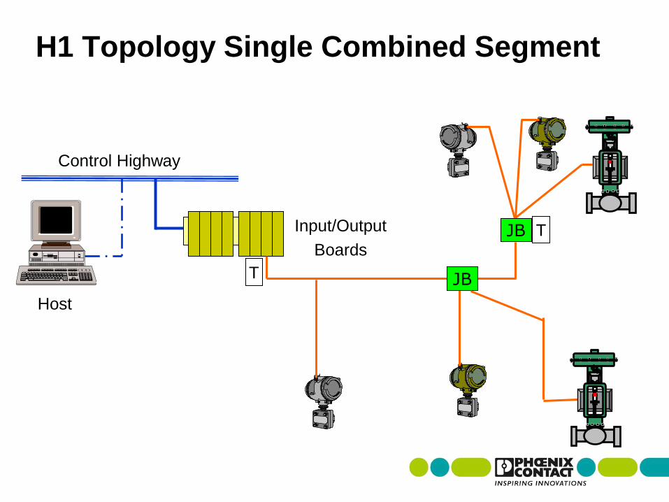
Control Highway
Input/Output
Boards
Host
JB
H1 Topology Single Combined Segment
JB T
T

24 | Profibus PA / Foundation Fieldbus |
Most Common Installation-Error: Termination
Differential signal
correctly
terminated
Signal
Signal with one
missing Terminator
Preventable using
mechanical
Terminator in Output-
Terminal

25 | Profibus PA / Foundation Fieldbus |
Power Supply
DCS-System
Foundation Fieldbus
Setup of a Fieldbus Segment
Field
FF Power
Supply
Spurs
Trunk
Zone 2
Zone 1 or 0
Intrinsically
safe Spurs
Control Room
Device Couplers for
Short Curcuit Protection Fieldbus-Barriers
for Ex-Isolation

26 | Profibus PA / Foundation Fieldbus |
Segment-Length – The real Limits
Length: theoretically 1900 Meters – depending on cabletype
Max 32 devices, but: Max Spur-
Length depending on number of
devices connected
realistic: 12 to 24

Section 3
27 | Process Fieldbus | Vogt | Interface | 28/Nov/2012
Section 1: Introduction / Differences between fieldbus & Analogue
Section 2: Physical Layer
Section 3: Innovation in Network Design

Continuous regulation of Temperature
Save and reliable process through
redundancy and diversity
Valid from the 1960’s to now
Single failures will be
Recognized,
Removed,
And won‘t influence production
Single Loop Integrity
Example of 4…20mA Control Loop
Sensor
Analog Input
Analog Output
Actuator
DCS Signal Conditioning Application

Daisy Chain-topology / Foundation Fieldbus or Profibus PA
Bridging a 2-wire-cable with power and communication
The first try

Continuous regulation of Temperature
Less IO cards !
Less cables !
Less Cabinets !
Easy planning / installation and startup !
Fully digital communication enabled !
Still highly reliable
The first try – installation example
Signal Conditioning Application
Mission accomplished?
Sagebiel / Fieldbus Evolution / June 2012 30

What happens at frequent field device exchanges
and expansions?
Short circuits cause segment breakdown
The first try – negative experiences
Sensor
Actuator
Application Signal Conditioning
Sagebiel / Fieldbus Evolution / June 2012 31

Include short circuit protection in each channel / spur
Improvement – Device Coupler
Sagebiel / Fieldbus Evolution / June 2012 32

Again Signal conditioning
Again Junction Boxes
But good segment protection during device
exchange and expansion
Impact of Improvement
Application Signal Conditioning
Sagebiel / Fieldbus Evolution / June 2012 33

Moving intrinsically safe isolation in the field:
High Power Trunk Concept
With FISCO Spurs at „Multibarrier / Fieldbarrier“
Next Improvement - Fieldbarrier
Sagebiel / Fieldbus Evolution / June 2012 34
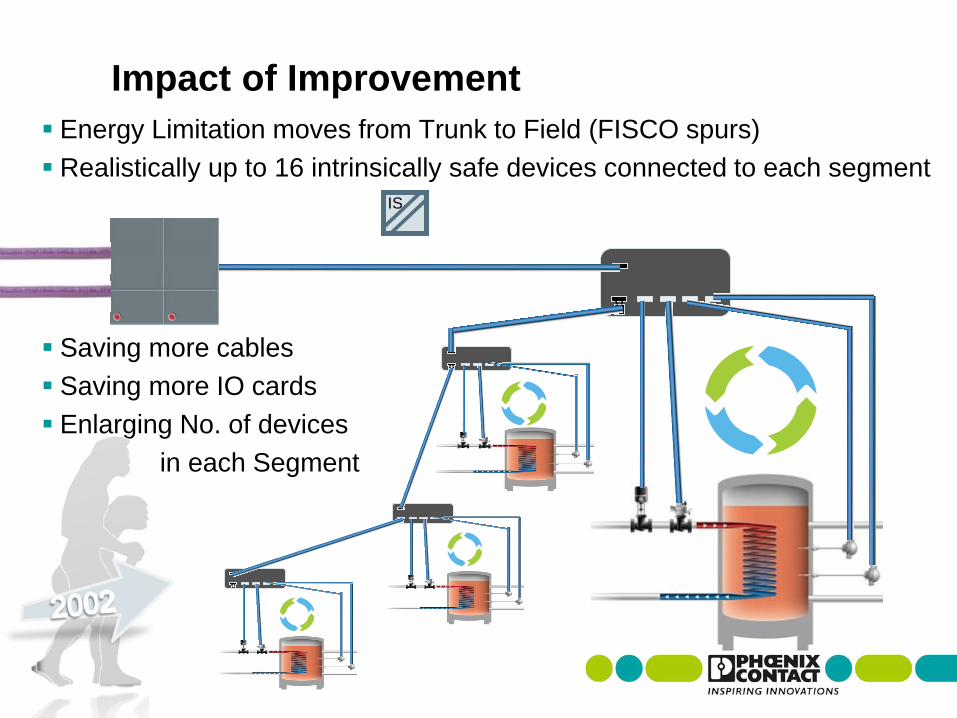
Energy Limitation moves from Trunk to Field (FISCO spurs)
Realistically up to 16 intrinsically safe devices connected to each segment
Saving more cables
Saving more IO cards
Enlarging No. of devices
in each Segment
Impact of Improvement
IS

Current limitation and Intrinsically safe isolation creates heat
Heat ages electrical components, reduces MTBF-times
Weakness of Brick-barriers

Current limitation and Intrinsically safe isolation creates heat
Heat ages electrical components, reduces MTBF-times
No single spurs fail
But complete bricks
Exchanging a brick means
shutting down the
complete segment
Weakness of Brick-barriers

Current limitation and Intrinsically safe isolation creates heat
Heat ages electrical components, reduces MTBF-times
No single spurs fail
But complete bricks
Exchanging a brick means
shutting down the
complete segment
Weakness of Brick-barriers

Isolating each spur separately
Cutting Bricks into pieces
Daisy Chaining fieldbus signal in a modular backplane
Final Improvement – Scalable Barriers
Sagebiel / Fieldbus Evolution / June 2012 39

Final Improvement – Scalable Barriers How we made it happen:
Sagebiel / Fieldbus Evolution / June 2012 40

Final Improvement – Scalable Barriers How we made it happen:
Hall 11.1 - A27
Sagebiel / Fieldbus Evolution / June 2012 41

Single failures will be
Recognized,
Removed,
And won‘t influence production
Single Loop Integrity
Hall 11.1 - A27
Sagebiel / Fieldbus Evolution / June 2012
Impact of Final Improvement

The modern solution – Scalable Barriers Overview
Exchange without segment interruption
Single Loop Integrity
Get rid of unused spare
Always ready for expansions
Channel 2 channel isolation
–Ready for the future – Mixing Ex ic and Ex ia
next to each other
Hall 11.1 - A27
Sagebiel / Fieldbus Evolution / June 2012 43

Modular Segment Couplers and Terminator
F+ F- S
Trunk In
Trunk Out
Spurs
Trunk In
(Terminator Installed)
Trunk Out (Terminator Installed)
Can hot-swap modules
with the bus in operation

Tailored installation
Not more than really needed
– break away from „spare“
No unused electronics in the field!
Easy installation-mixing
FISCO and FISCO ic
Zone 0 / 1 Zone 2
45 | Process Fieldbus – highly available| | Business Development | 2011

Expandable during operation
Uninterruptably
Fast and easy, thanks T-Bus
Termination errors impossible
Easy installation-mixing, also later on
FISCO and FISCO ic
Zone 0 / 1 Zone 2
46 | Process Fieldbus – highly available| | Business Development | 2011

Exchangable fail-safe
Without loosing contact to Process
Single-Point-Integrity
Ideal for use in
highly available applications
47 | Process Fieldbus – highly available| | Business Development | 2011

Continously scalable
Also the Fieldbus Power Supplies
redundant simplex
48 | Process Fieldbus – highly available| | Business Development | 2011

Each Segment highly available on its own
Segment for Segment expandable
Exchangable - Also each base
50:50 load-balancing thanks ACB
(Auto current balancing)
Basic-Diagnostics via Relay and LED
49 | Process Fieldbus – highly available| | Business Development | 2011

The Junction Box for scalable Use
Pre-wired
Space saving
Easy connecting
50 | Process Fieldbus – highly available| | Business Development | 2011
Step 1: Choose pre wired
Junction Box
Step 2: Order the desired
device couplers / isolators
Step 3: Mount cable glands
depending on cable type
Step 4: Snap on the Tbus
connector and couplers, when the
instruments are in place

www.phoenixcontact.com/processfieldbus
51 | Process Fieldbus – highly available| | Business Development | 2011


![Profibus PA Fieldbus Display [ Revision 2 ] and Fieldbus ... Instruments... · Profibus PA Fieldbus Display [ Revision 2 ] and Fieldbus Indicator Fieldbus Interface Guide. ... Siemens](https://img.pdfslide.net/doc/110x75/5b2fe38e7f8b9ae16e8da83d/profibus-pa-fieldbus-display-revision-2-and-fieldbus-instruments.jpg)